
Leaderboard


Popular Content
Showing content with the highest reputation on 01/13/20 in all areas
-
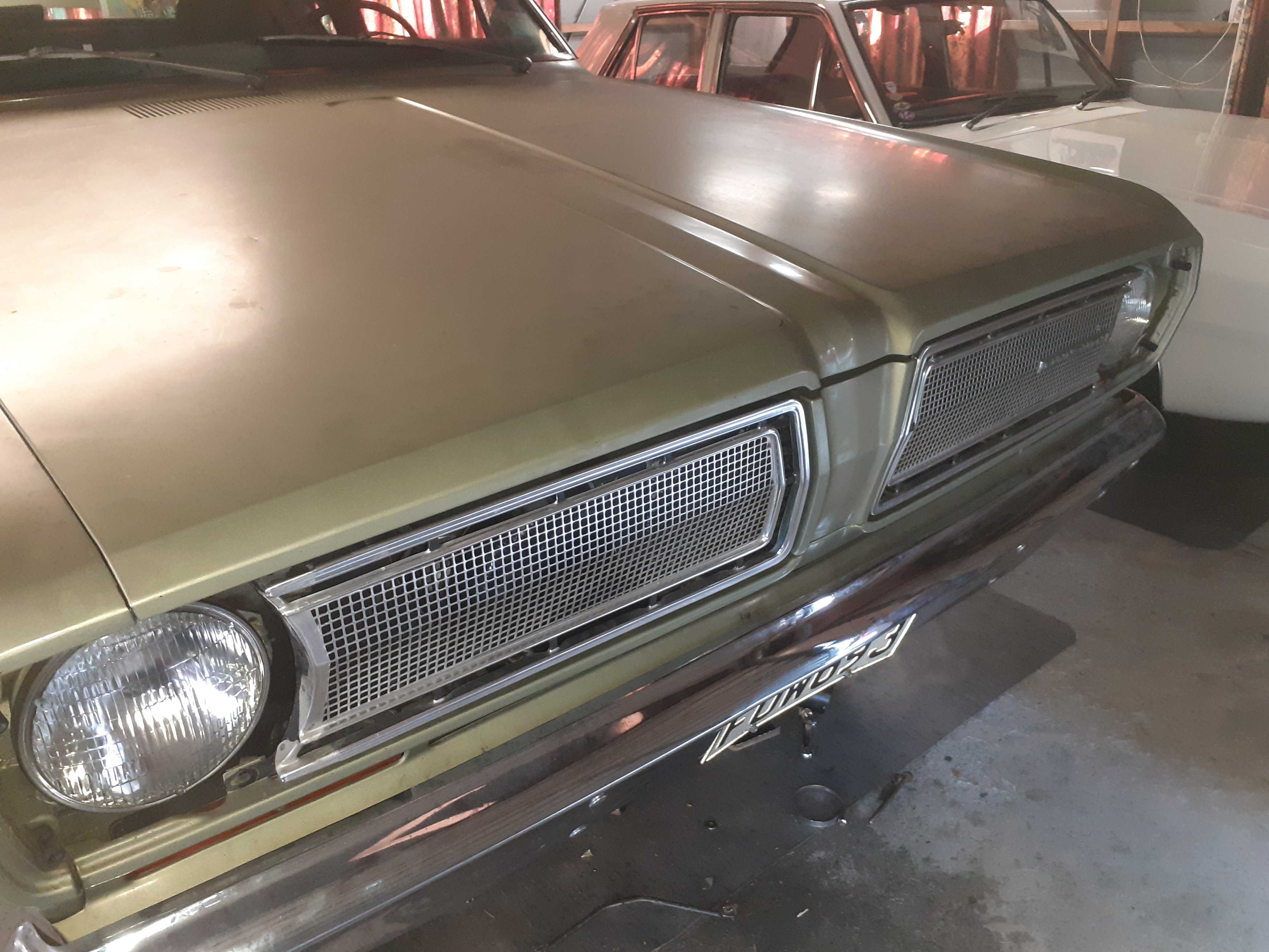
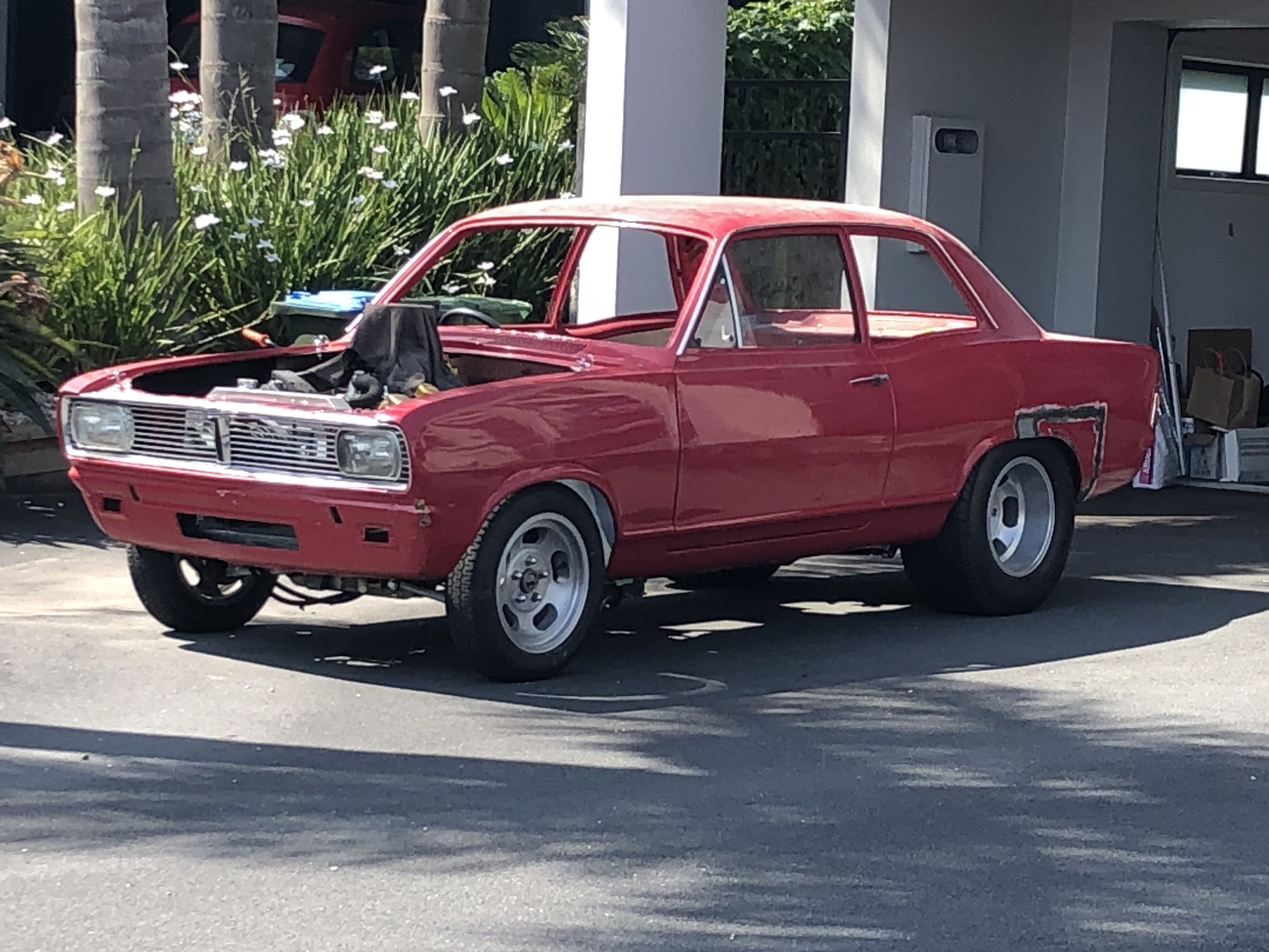
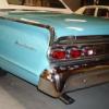
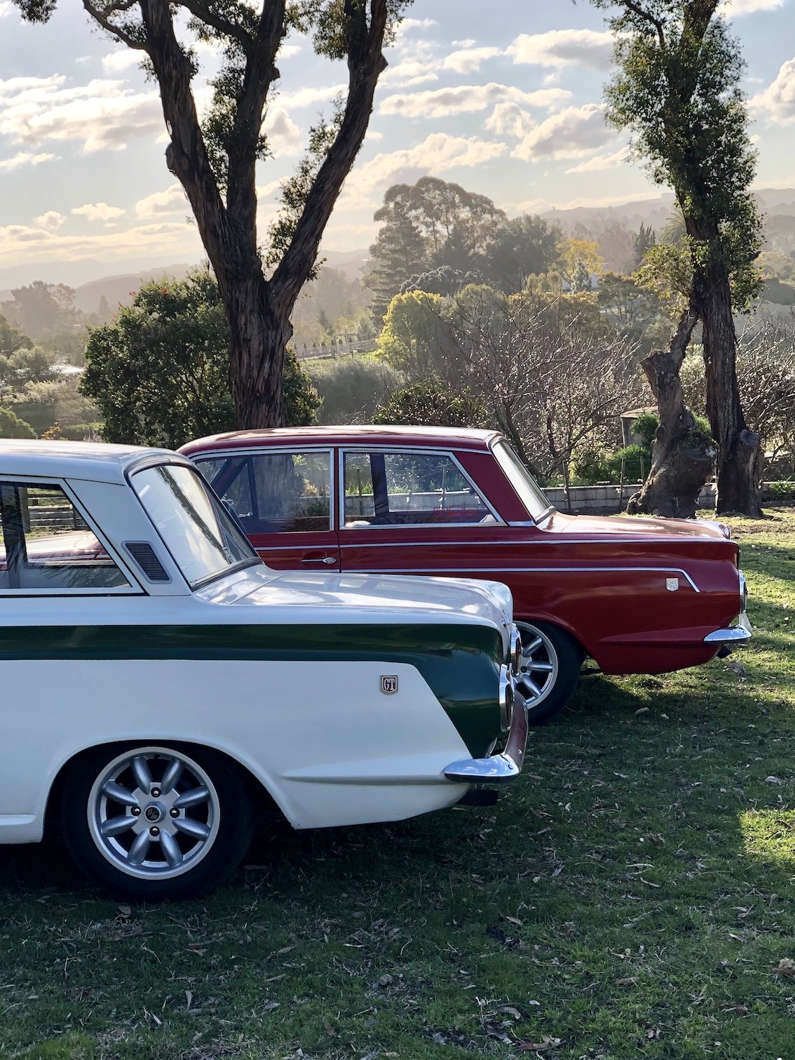
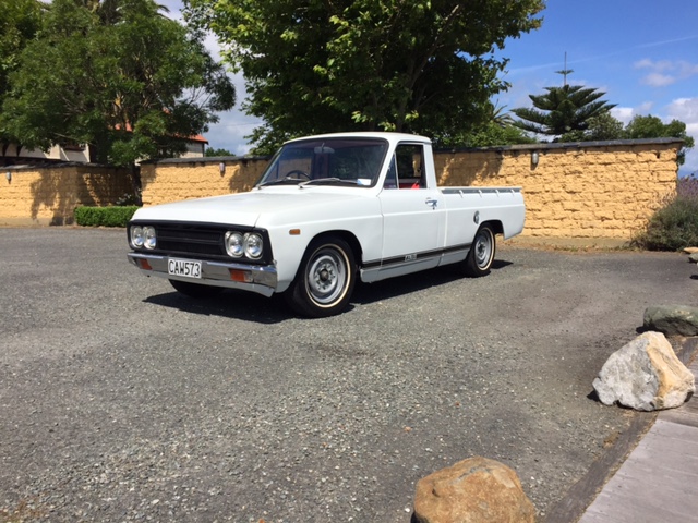
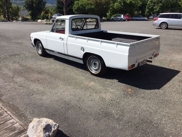
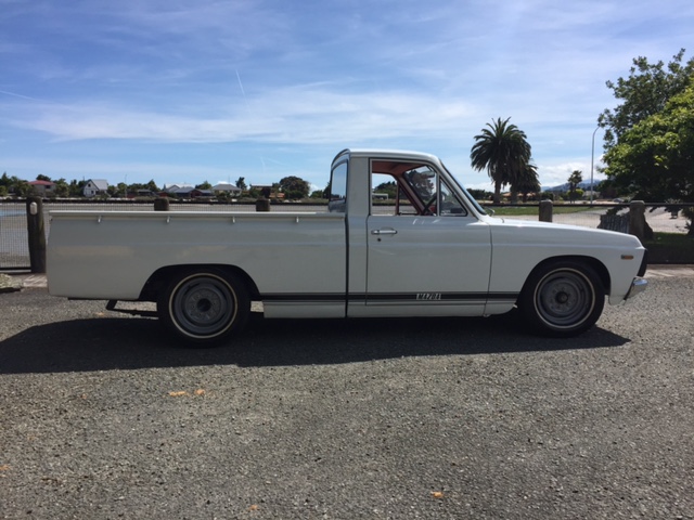
So I was home over the Chistmas period and gave it a clean up inside & out, ripped off the crap aftermarket whistling roof-racks, replaced broken radio antenna mast, replaced the sagging roof lining, re-glued up some of the door seals, replaced speakers, refurb'd/tinted rear tail lamps, replaced rocker cover gaskets and slapped on my Mk1 GTO 16" wheels with new tyres. I still need to replace some broken interior plastics and sort out the sloppy automatic shifter.12 points
-
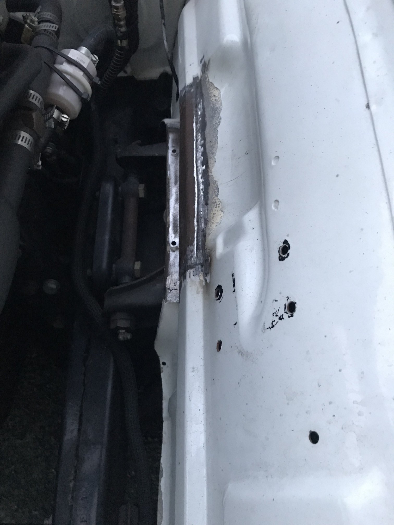
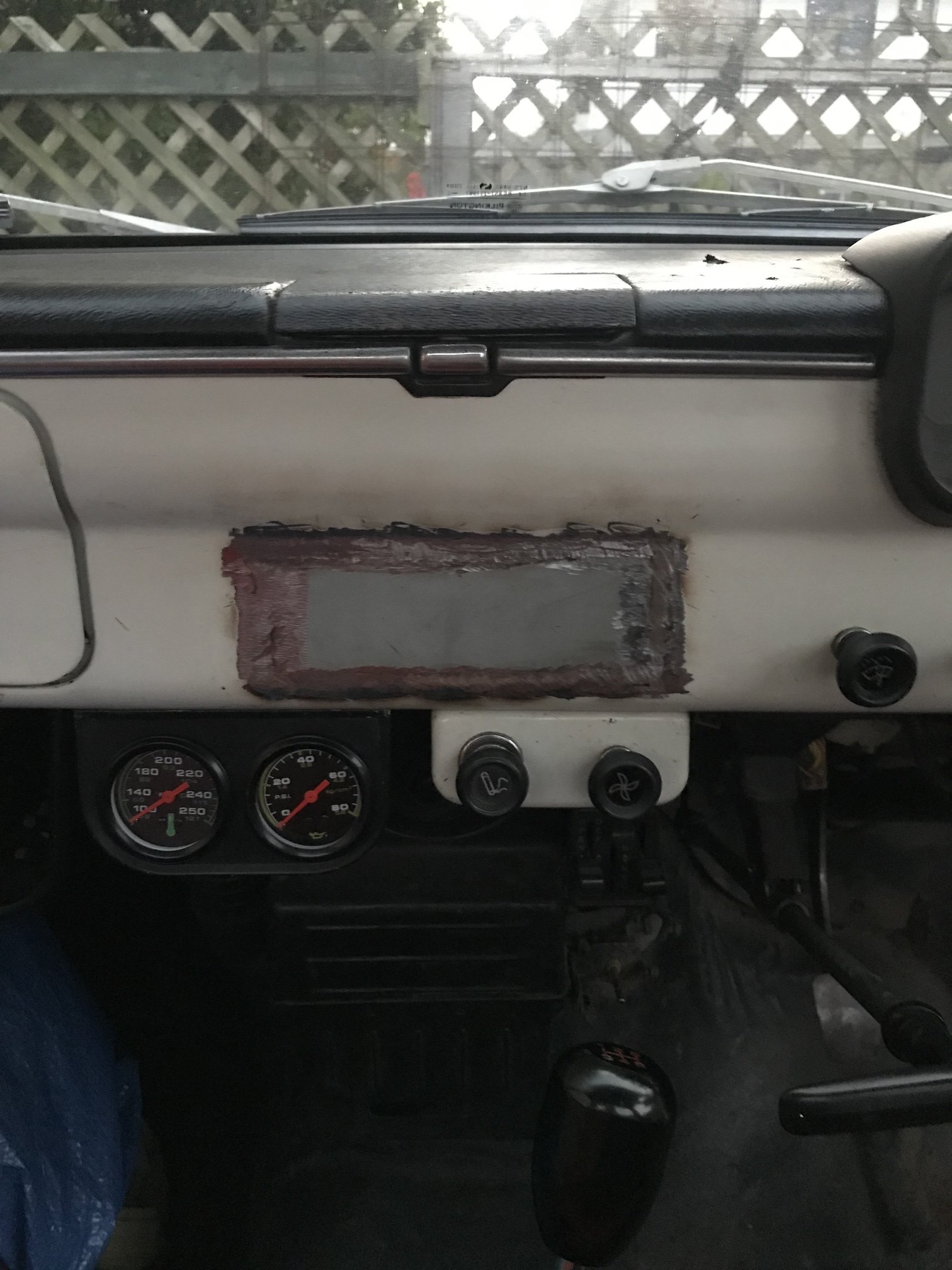
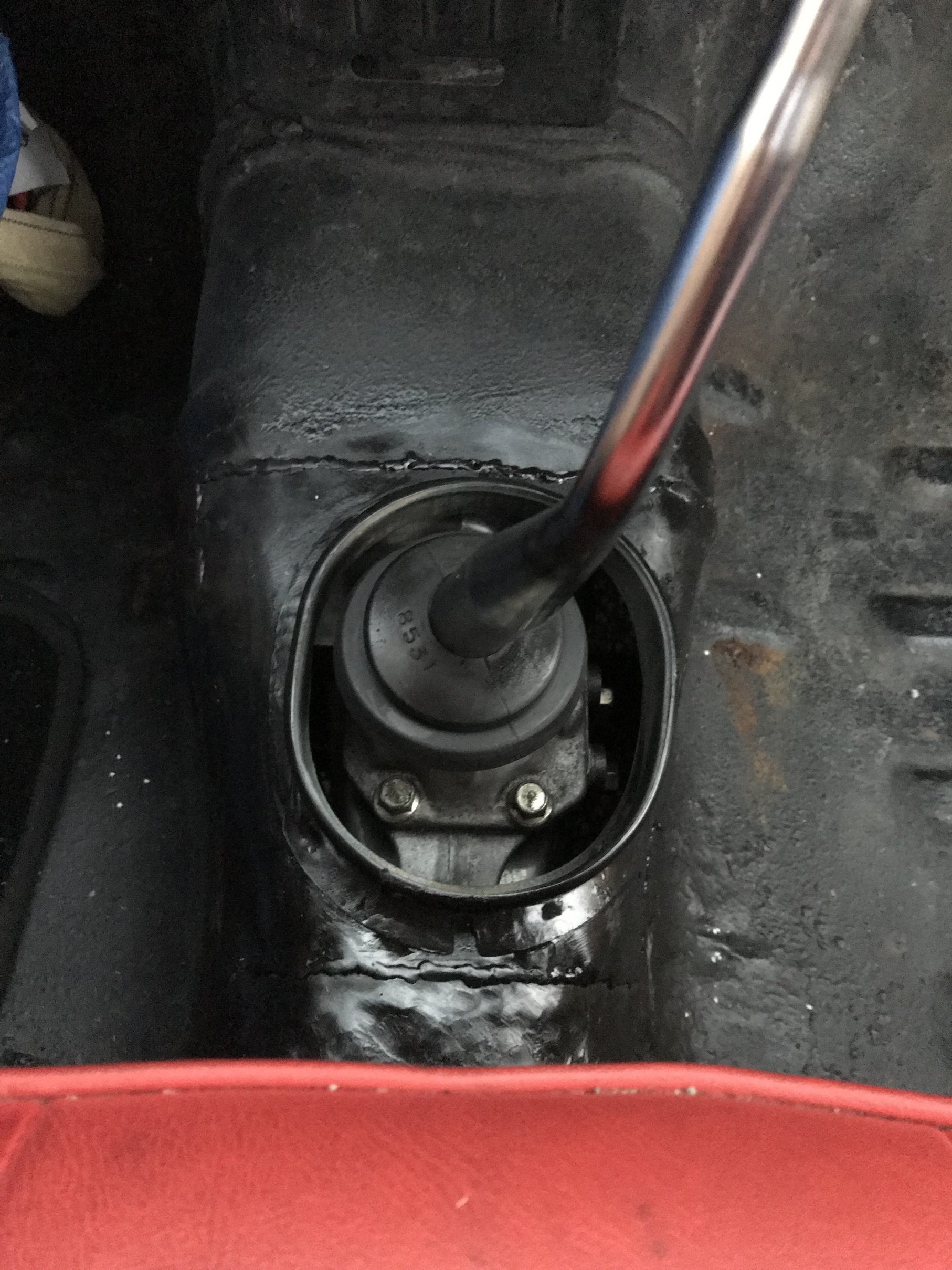
Over the Christmas break I dropped this old girl out to Alex @yoeddynz, really stoked with his work, he rectified the holes that had been cut in my inner guards, blanked the stereo hole that had been butchered and added the floor shift tunnel I had cut from the courier. It was a long drive out to the Abel Tasman ringing its guts out trying to do 100kph so next on the list is putting the courier diff nugget in, fingers crossed it should be a 3.3 or 3.5 so should make a huge difference from 4.8 hopefully. Also the gearbox is really noisey so will swap that out at the same time.
 10 points
 -
well, that was fucking stressful. first time ever laying a candy/3 coat colour and it so very nearly went very very wrong. i completely fluked it and managed to get it looking right but i was seconds away from disaster on more than one occasion. im fucking turbo stoked with how it looks, its got some dust in it but i couldn't give a fuck, theres way more right than there is wrong and thats a fucking win. 2020-01-09_06-20-37 by sheepers, on Flickr 2020-01-10_07-39-39 by sheepers, on Flickr 2020-01-10_07-39-48 by sheepers, on Flickr 2020-01-10_07-39-58 by sheepers, on Flickr 2020-01-10_07-40-05 by sheepers, on Flickr7 points
-
From Link help file copy/paste: "A large number of technical inquiries are received regarding problems due to incorrect wiring of auxiliary outputs. Incorrect wiring of solenoids and relays to auxiliary outputs can result in the following symptoms: · ECU not powering down when the key is turned off. · Accessories such as engine fans coming on when the key is turned off. · Repeated clicking of relays when the key is turned off (machine gun sound!). · ECU draining the battery over a few days. The root cause of these problems is the wiring of hot fed (direct from the battery positive terminal) or ACC fed (key in accessory position) solenoids or relays to ECU auxiliary outputs. Each auxiliary output basically consists of a low side driver and flywheeling diode. A low side driver is a power transistor that can switch a load to ground. Flywheeling diodes are required for the driving of fast switching devices such as ISC solenoids and VVT solenoids. Flywheeling diodes are also essential for reducing radio interference noise. Unfortunately, the placement of flywheeling diodes means that if power is applied to auxiliary outputs through a solenoid or relay when the ECU is powered down current will flow through the flywheeling diode causing the ECU to power back up. As solenoids have some resistance, the current that flows back into the ECU (back feeds) is not usually enough to power the ECU up properly resulting in the ECU powering up and down continuously. This causes unusual behavior by the offending solenoid and possibly other solenoids as its current is switched on and off."4 points
-
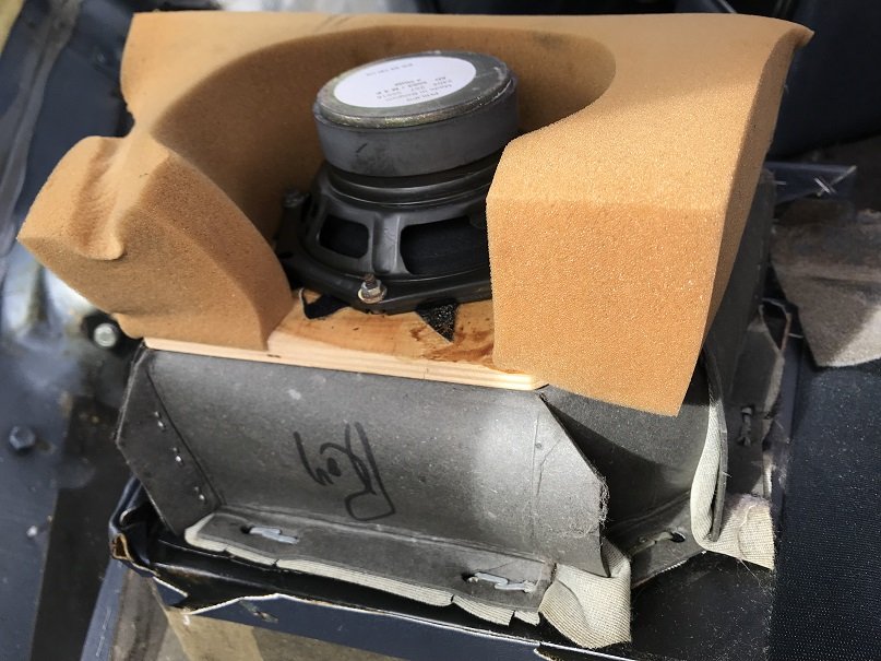
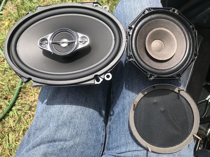
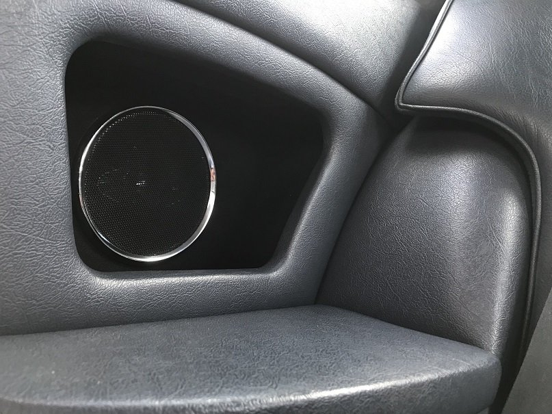
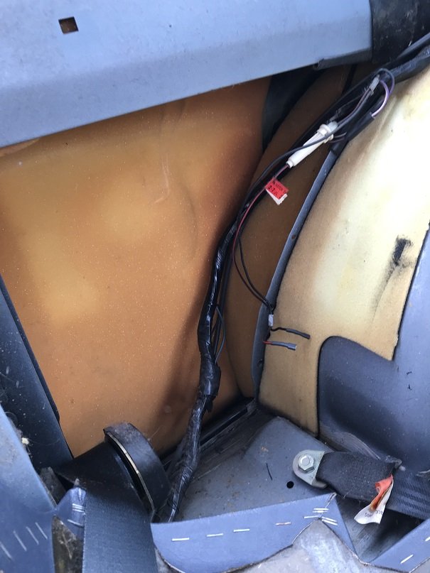
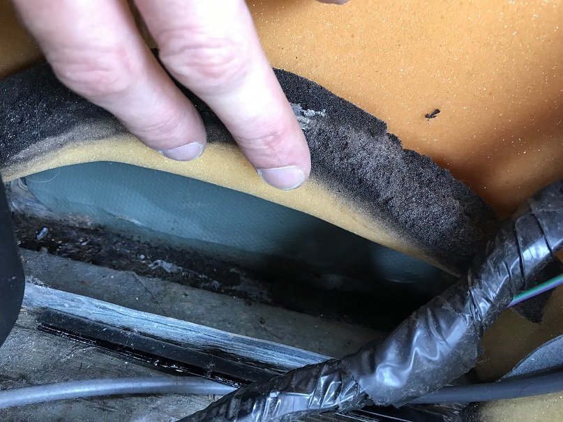
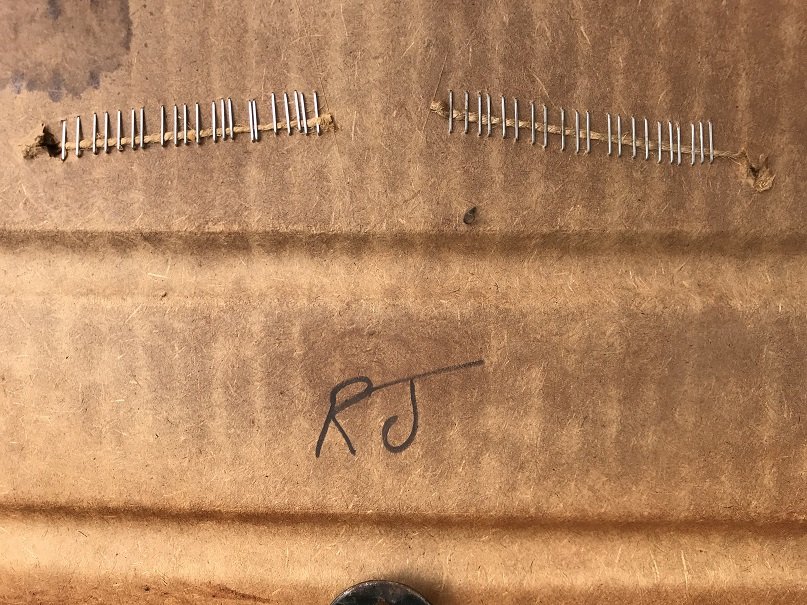
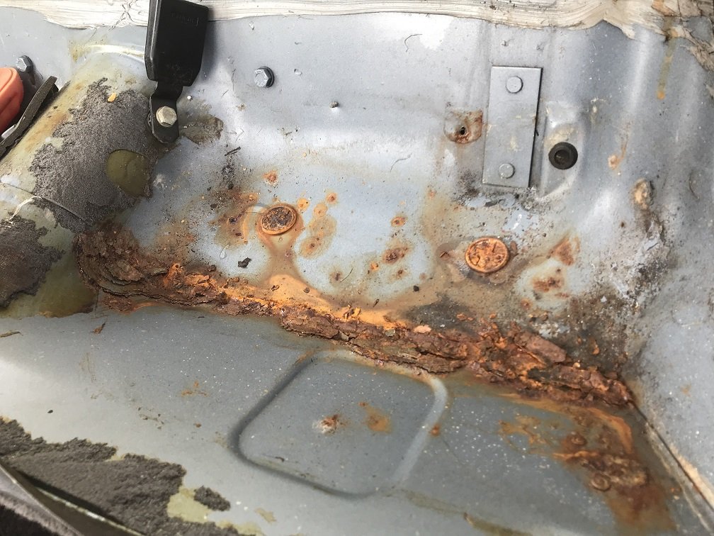
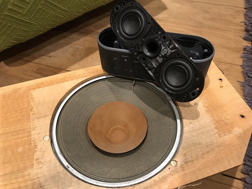
I needed to replace the speakers in a musical keyboard, so I thought I'd scavenge the factory rear speakers out of the Jag for this purpose and put some new ones in their place. Sounds straightforward. To take out the interior trim panels which hold the rear speakers, you have to take out the rear seat base, rear seat back and front seat belts. The lap section of the belt attaches to a rail which is bolted to the floor of the car, and the lower threads of its mounting bolt protrude below the car where they get all corroded. When you remove these bolts, they get destroyed and their nuts (welded to reinforced sections of the floor) get damaged. Then you're left with no seat belts. So then you have to drive around with no seat belt to visit speciality stores during business hours and buy some stupid imperial 7/16 UNF bolts and a stupid 7/16 UNF thread tap that you will never use again. Aaanyway, here is one of the factory rear speakers: They're mounted to an actual piece of plywood, rather than to flimsy door card like the front speakers. As with the fronts, though, the speakers are mounted on the rear of the panels via threaded rods which are welded to the speaker grilles. I measured the plywood panel dimensions and got the biggest suitable speakers which could be mounted from the rear without modifying the panel (most speakers weren't suitable for rear mounting as they don't provide a standoff ring to stop the edges of the cone contacting the panel). Here is a new speaker, a factory speaker and the factory grille: Then I recessed the mounting nuts for the speaker grilles and cut down their threaded rods as short as I could. This allowed me to slap the new speakers onto the back of the panel while keeping the factory speaker grilles in place. Result: It looks factory (good), and sounds factory (not so good) except a bit clearer. There's still not much bass and the sound starts to distort when the head unit is still quite far from its maximum volume. I probably won't try to improve things further though, because there's no ideal spot for amps / subs in an XJ-S. While I had those interior panels out of the car, I got a look at Jaguar's superb rust traps. Behind the rear speakers / below the rear side windows, there's a join where the bodywork meets the sill. Rather than installing drain holes in case water gets in, Jaguar just fitted lots of foam to absorb the water: This seems like it would promote rust, and indeed it does. My car's not too bad for rust just yet, which is why I was not prepared for this rust under the sound deadening below the rear seat base! Water must have been getting in and pooling at this join, helped by the foam stuff. I took a few handfuls of rust out, revealing some holes. However, the holes revealed that this seat framing is not the floor of the car - there's heat insulation below here to stop the passengers getting toasty bums from the inboard brakes and exhaust. I just hit it with rust killer / corrosion primer / fish oil and hid it away for another day, since it's very easy to access. Before putting the rear seats back in, I noticed they were made by the notorious Jack the Stapler:
4 points
-
New Year, New meet! This Thursday (I know, I know...) 16th January, 6.45pm Down at our usual place in Plimmerton. Map below for any newbies! Come have some sharns and a good ol' catch up. I'm a Map! Across the road from that address ^ in the parking area.3 points
-
Sweet, that will just be a current limited power supply, so when the BMS disconnects the charger, the current stops flowing so the light will go green. Wait a bit for the BMS to pull one of the cells down, and it will (should) turn the charge back on and the light will go red again. If it does that, then you're in business.3 points
-
Try as might I couldn't get the speedo to work, then the rev counter started playing up too. I bought most of another cluster and swapped out the speedo but it was an earlier version and wouldn't work either. It was worth it tho for the complete front plastic bit, which was broken on mine. Apparently the clusters are a bit shit anyway so I started looking for aftermarket ones, this was fucking depressing, like $480 bux each for a Speedo and tach. I rang Young's automotive just to see what they could do but got the same story. Then the dude asked me to hang on and came back saying he had some old stock isspro gauges in mph that he could do for 200, fuck yea I said. Getting these to work was interesting, but once I had it sorted I cranked into the mounting. This was the problem, all the shitty tracks and plugs on the fpc right where I wanted to put the gauges; So after mounting the gauges I recreated the shit I needed for the other gauges and lights from some prototyping PCB board, kind of rough but within my capabilities; The gauges are smaller than the originals, but not too stupid looking. I got a plate laser cut to cover the too big holes and where the odometer was. Because the Speedo was in miles, and the odometer would also be in miles, I just calibrated it so the miles show as kilometers and used a black permanent marker to black out the shit that contradicted that lol. When I hooked it up half the lights didn't work and I thought I had fucked it up, but it turned out half the bulbs were blown, I replaced those and good to go. Not sure what happened there.. Good to go. I also got it hot to see if the fan cycled, it didn't and it turned out the fuse was blown as it was a bit small. I put in a bigger one and checked again today, all works as expected. The rad must be effective cos the fan runs for 30 sec then takes 5 mins to start up again when sitting there idling. I also put a manual switch in there just in case. The power steering is leaking but this is just an o ring issue, I will sort that next.3 points
-
I put this outrigger on. I think for certification I need to guard the belt drive? Then, I rolled it outside and it stood for the first time in its life on it's own. As a father of 3, I can say that this emotional experience far eclipsed watching my own kids takes their first steps. So close, yet so far away for starting it up.
3 points
-
3 points
-
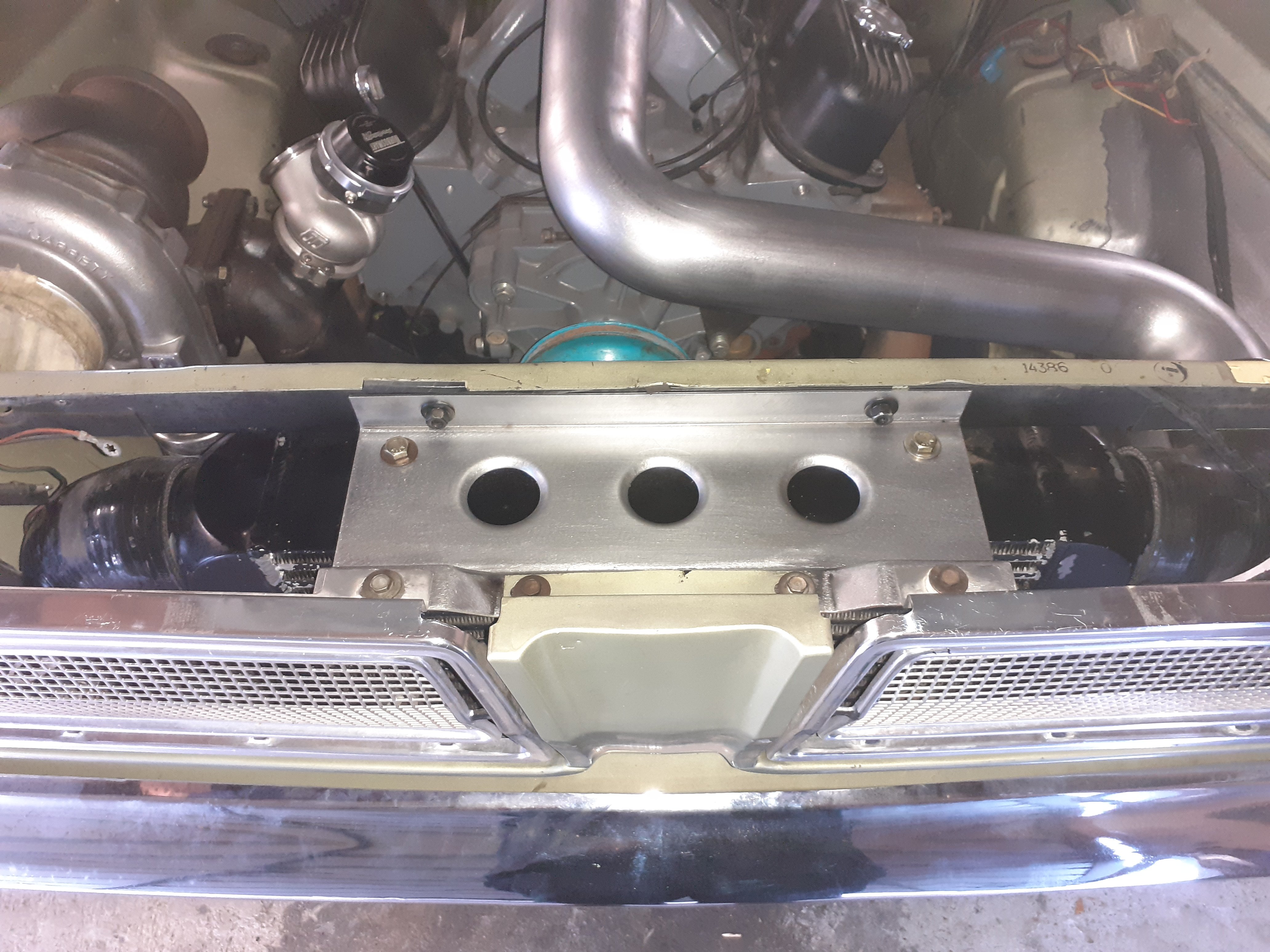
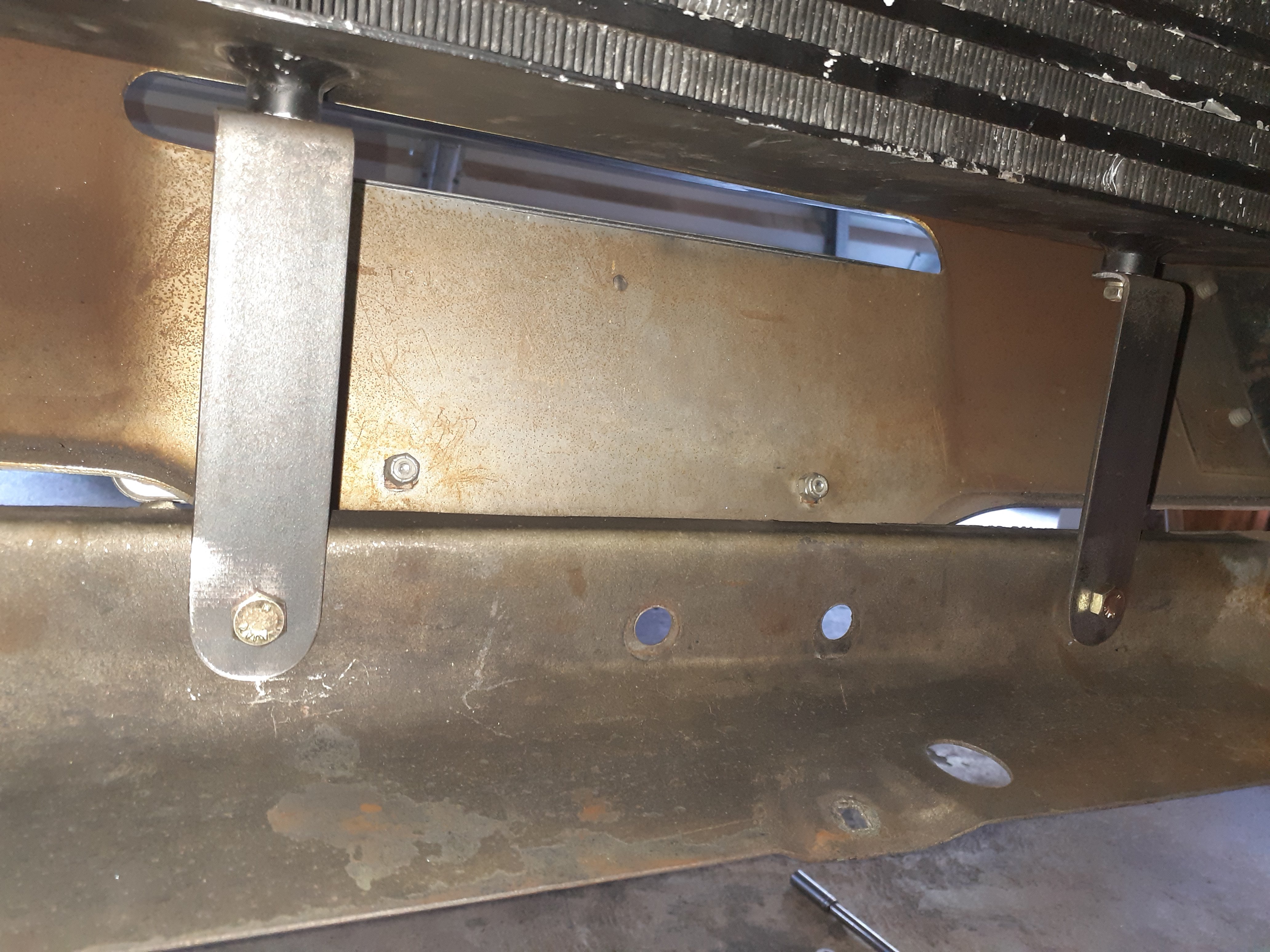
@RXFORD /Matt at tin tricks helped me out again making this fancy bracket which gets rid of the bonnet catch stuff and mounts the top of the intercooler, grilles etc and I made some brackets for the bottom of the i/c Also spent a while making the engine fit under the bonnet, cut a bit out of the mounts and spacers under the front subframe, now it has 1x bees dick of clearance
3 points
-
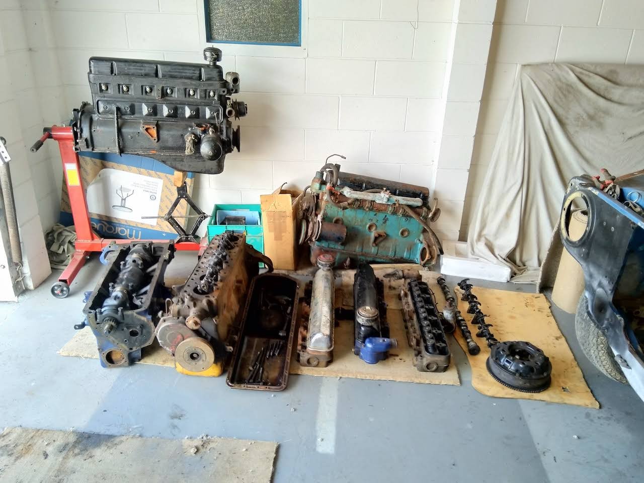
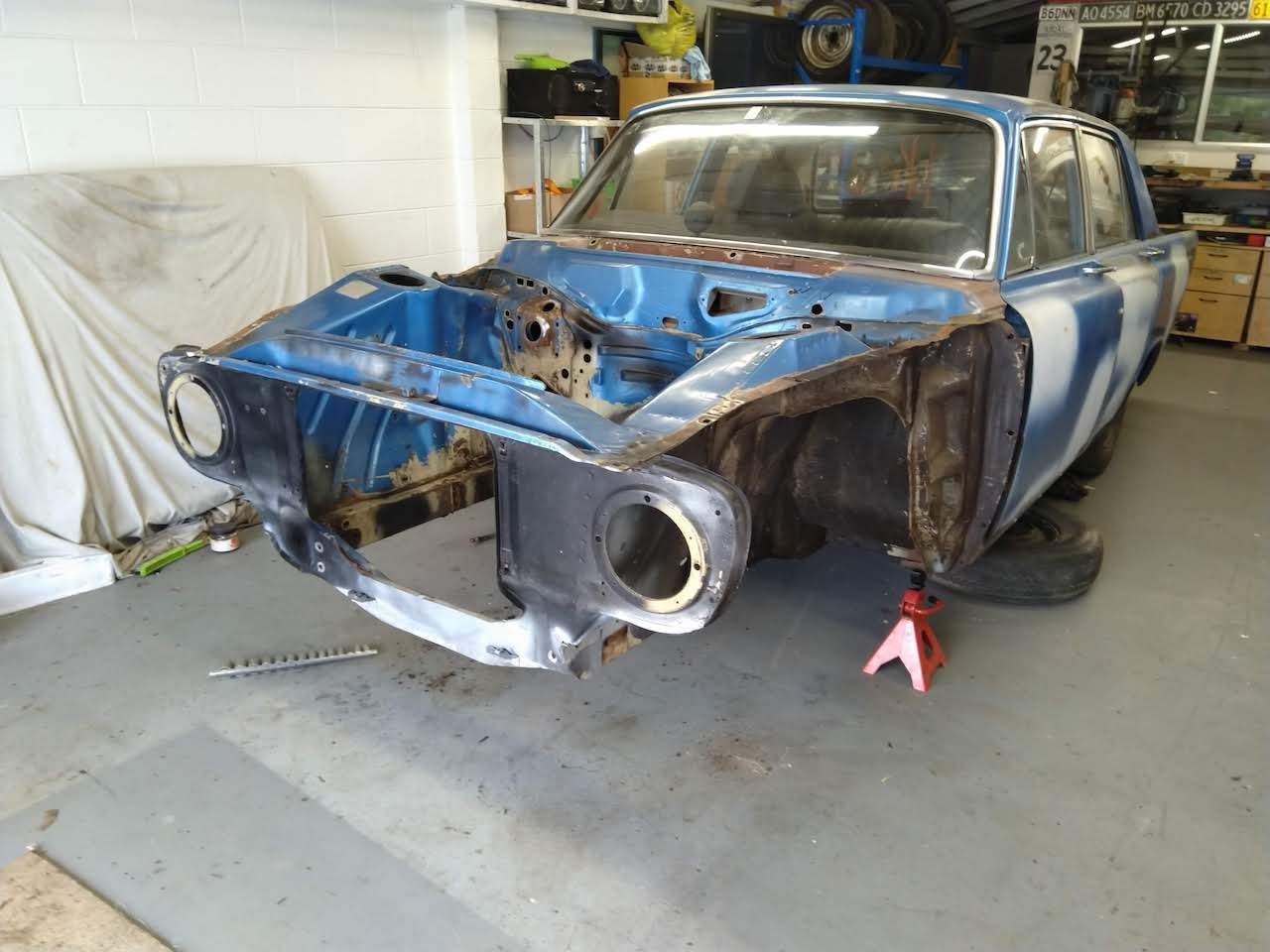
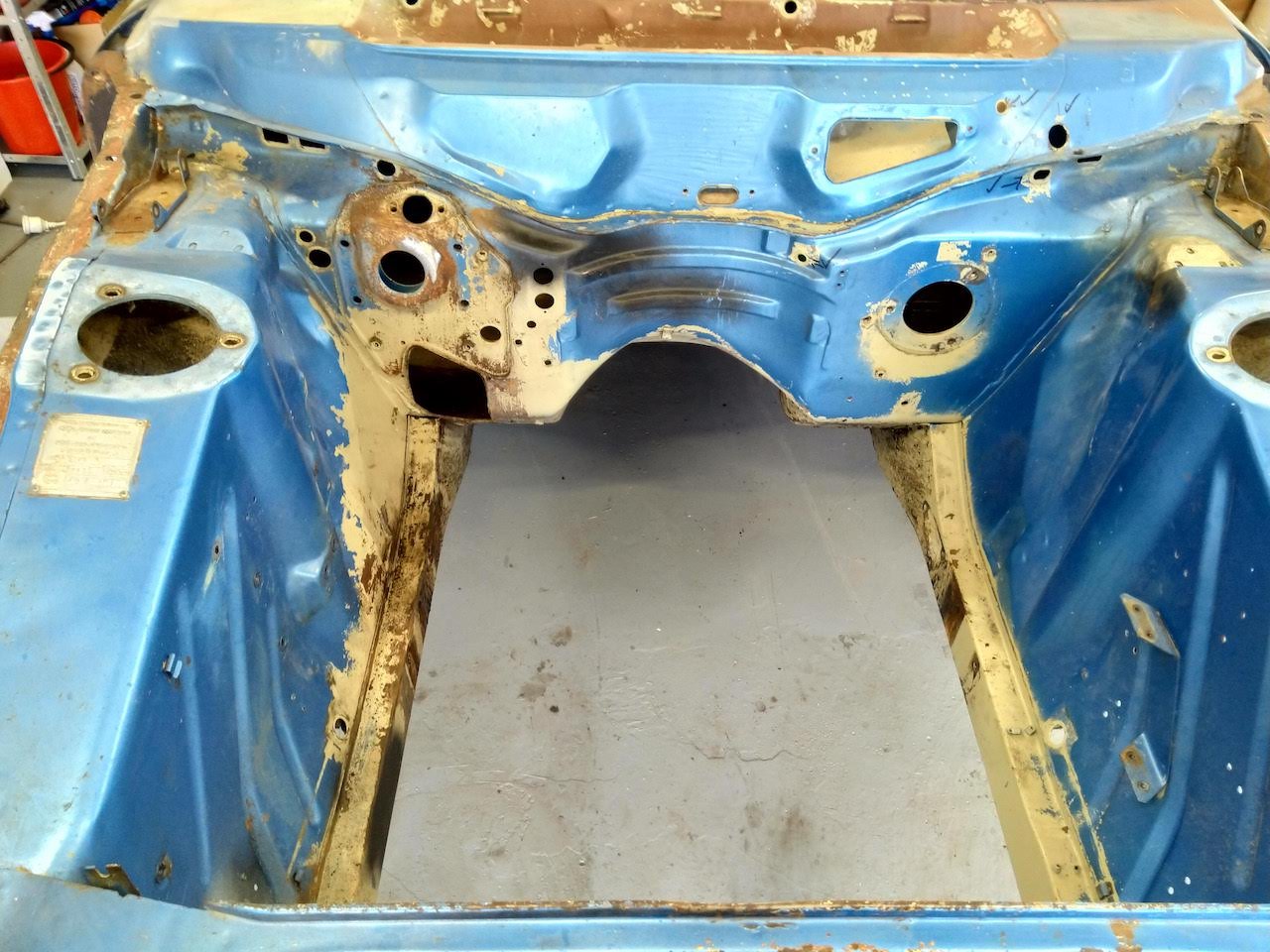
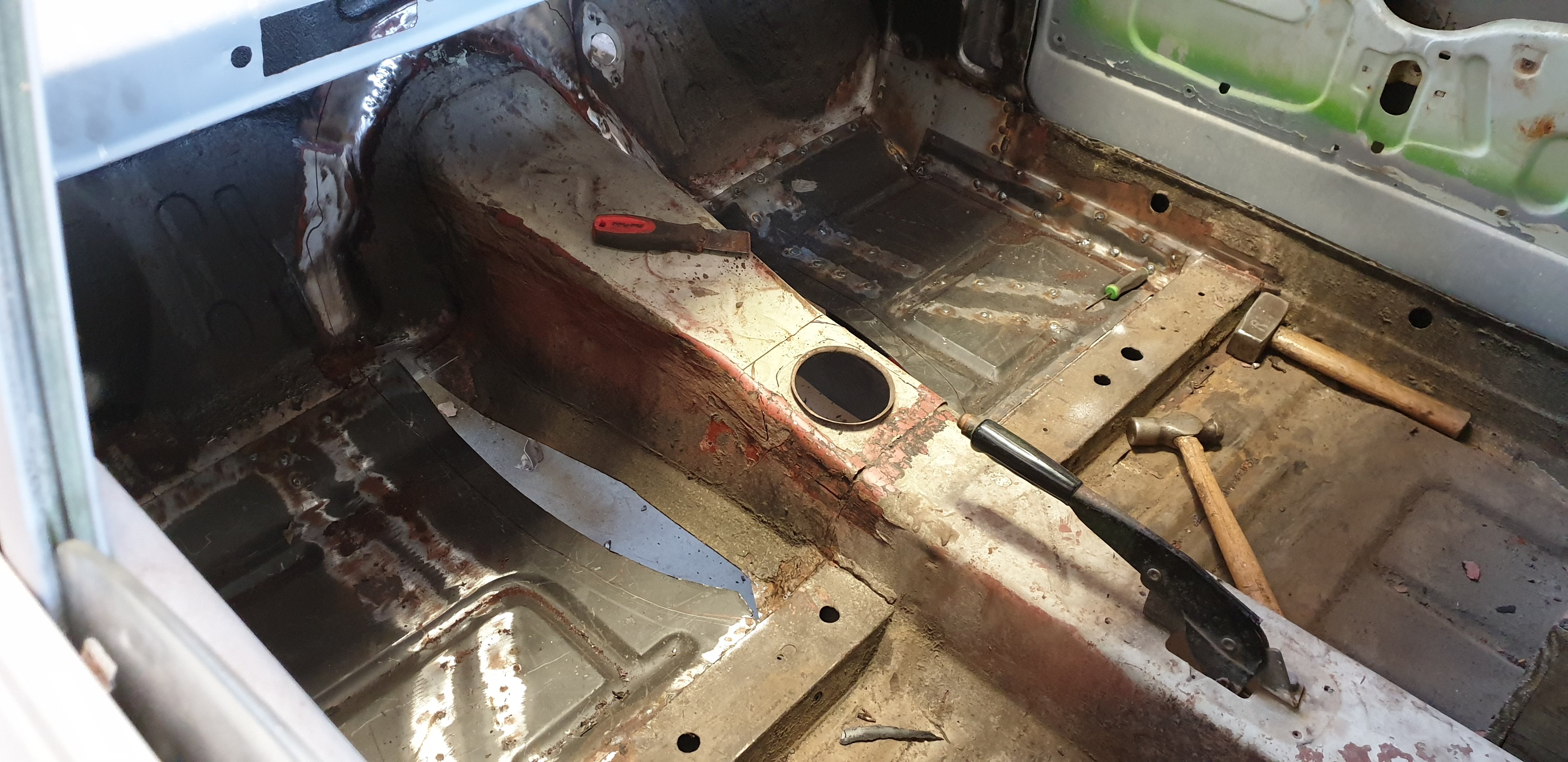
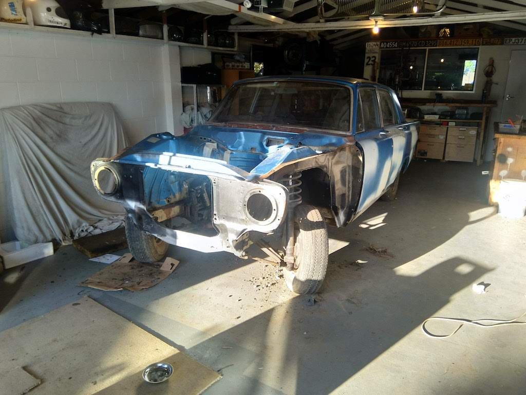
A guy on facebook was giving away some motors and parts, after finishing his project. Drove over to Greymouth to collect them. Now got 4 parts motors, so should hopefully have enough good bits when it comes to building a motor for it. Finished stripping the engine bay, removed suspension and cross member. I have made a start removing the underseal from the guards, only been finding some light surface rust so far. Will continue removing the undereseal and make a start bare metalling the engine bay next.
3 points
-
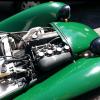
*Fixed Ran the ecu feed straight from the ignition feed instead of the + common Thanks chaps, can always count on you lot to help troubleshoot for us plebs2 points
-
where does the 12v+ come from on the coil of fuel pump relay ? Sounds like how you have it setup should work. Ideally you want your main power feed from battery -> straight to fuse box/ fuses . then out of fuses to relays I like to run the ecu on its own relay triggered by key on. Then a second relay for the fuel pump. ecu supplies negative to coil Then if you want to get fancy; As well as the fuel pump relay doing the fuel pump. use it to trigger the coil on a 3rd relay, which does all your injectors, coils etc. This way if the engine stops for any reason, the ecu turns off the fuel pump and also kills power to injectors and coils and what ever else is on the 3rd relay. just bit of a safety feature2 points
-
I did the black cover sanded fin look on my Camaro.. I liked it a lot
2 points
-
So this has come a fair way, have used a Patrol steering column very kindly supplied by @ThePog. Now have steering collapsibility etc. As I had to change the firewall mounting etc, I moved it along so that it lines up with the steering box and all is good in the world, except the shaft is still too long. This isn't too much of a problem, I just need to cut the shaft to length and have it re-splined. Is this a job any old engineer can do or is there someone specific I should contact/someone anyone can recommend? From what I understand this is ok as the shaft is just mild steel and isn't being welded? @cletus any input here?2 points
-
^ this is the cause.2 points
-
so a BMS like that will only have a shunt of 55mA or something teeny like that. So to discharge a cell thats over volt will take a long ass time, and you need it on charge for hours. Especially first time to balance them all. Make sure its kinda working though by making sure you have power on the output, and the BMS is actually working, or else it will not protect the cells when charging and you might kill a few. Though if any of the cells measure too low it wont turn on, so it could be working without the output being on. When you say it switched off, was that the charger saying it was done? or did the BMS cut it off? or you turned it off? What is the charger? Just a current limited power supply? or something more fancy? other option is just using a smaller single cell charger to charge each set of cells of 4.2V and when charged do the next and so forth to 'top balance' all the cells in the pack, and then hope for the best after that.2 points
-
If it fits in a boot I can help you, but it is drop at bro repairs can one of those guys grab it for you?2 points
-
I could just bort that shit up and run the gauntlet.2 points
-
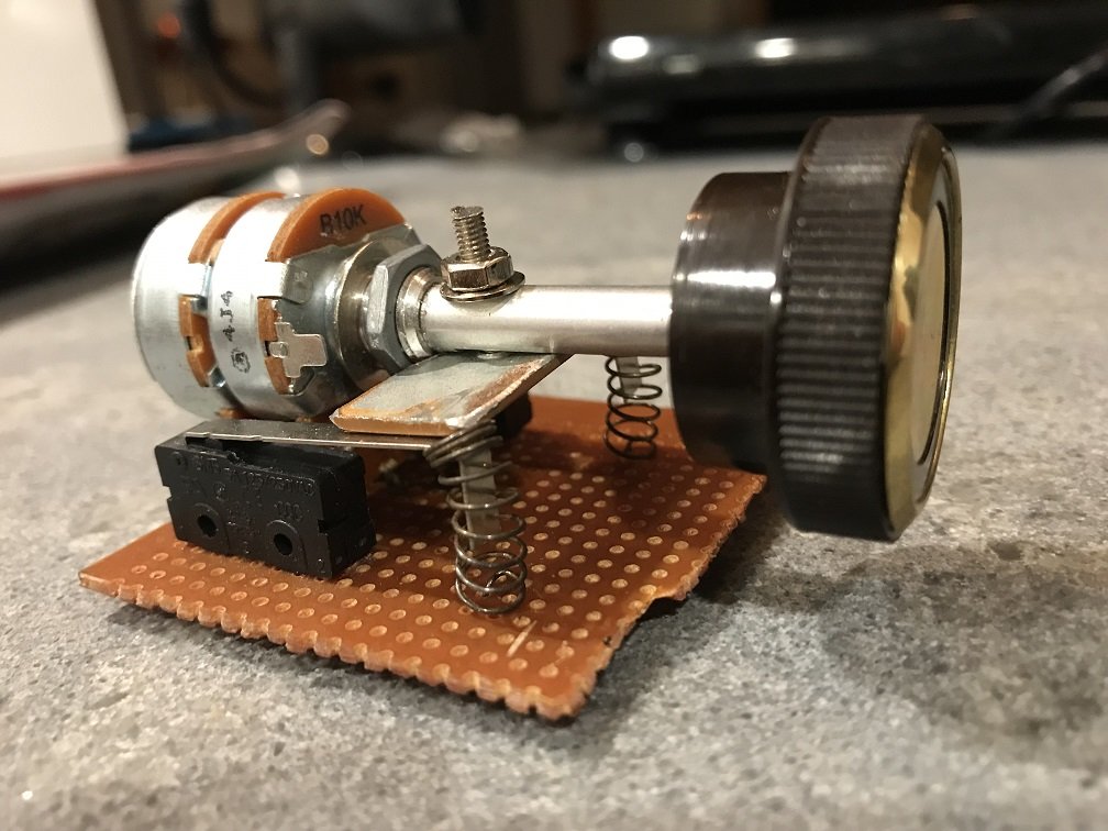
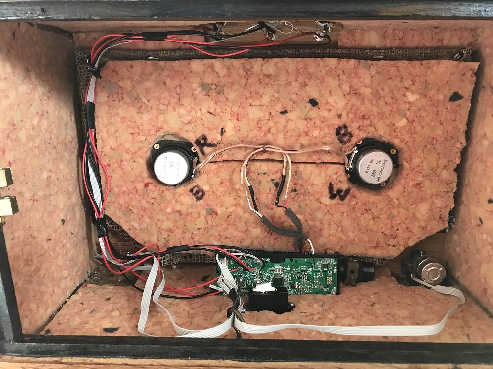
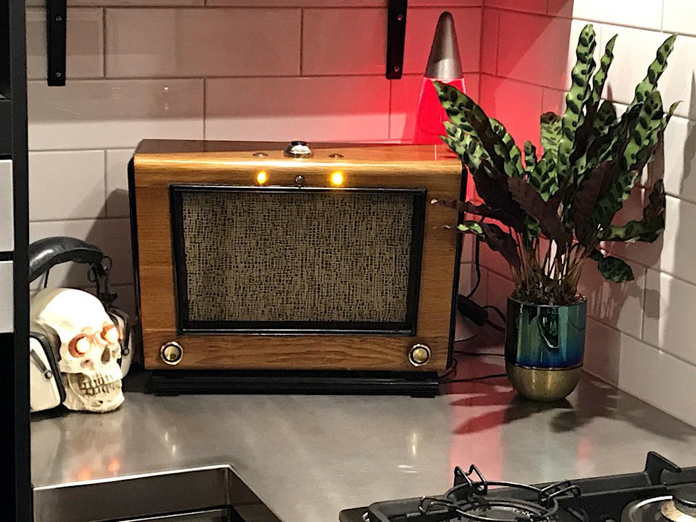
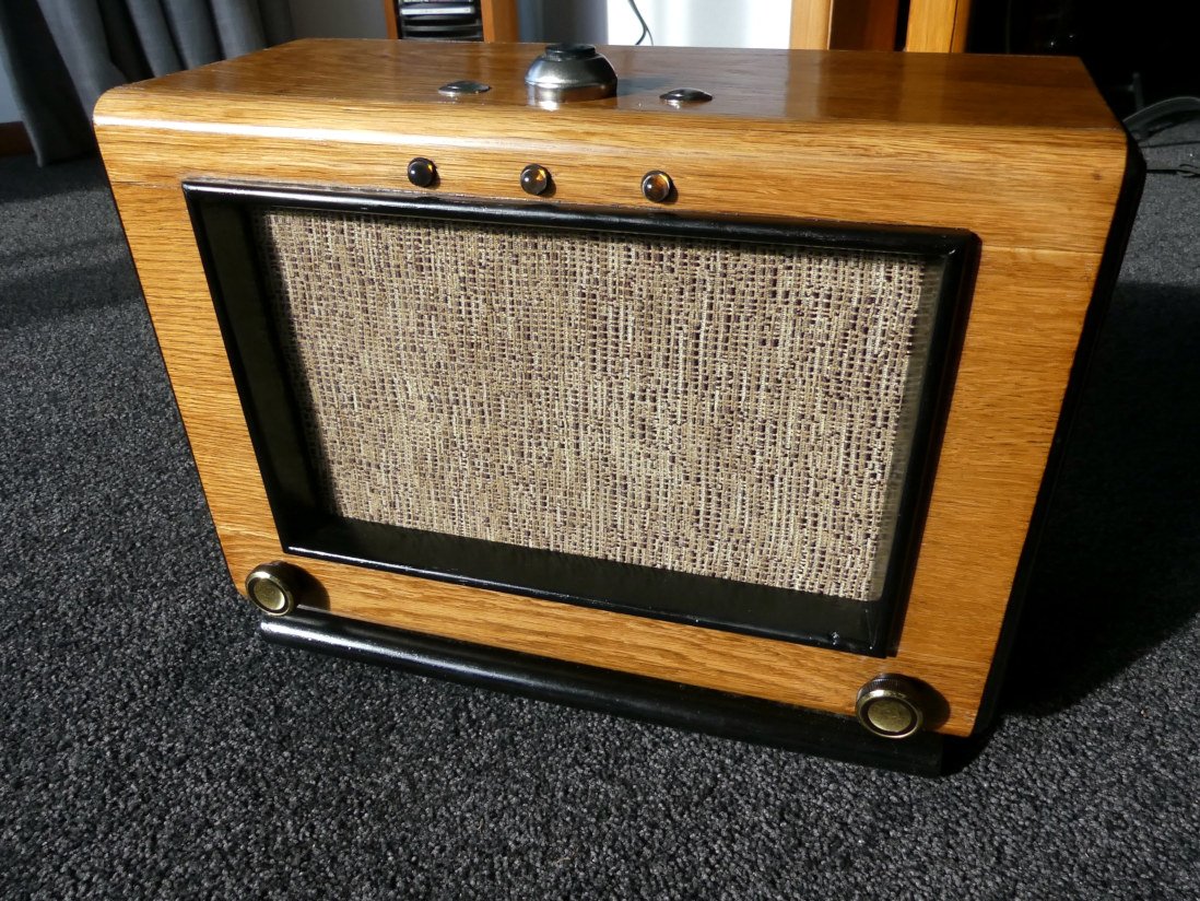
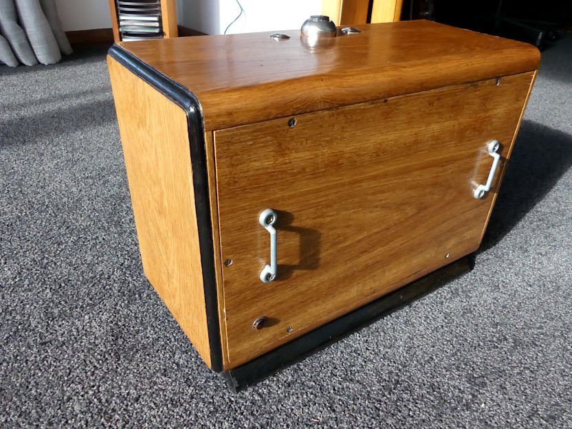
From the ever-expanding catalogue of Thousand Dollar Supercar's patented useless projects comes this: a bluetooth speaker. ...but it's bigger and more hipster. I started with a little bluetooth speaker I was given years ago, and an old extension speaker from TradeMe. The extension speaker (branded 'Tesla') is from the days of valve radios - you would hook it up to your radio for Ye Olde multiroom surround sound. Here is the partially-disassembled bluetooth speaker next to the single mono driver and front panel from the Tesla cabinet: Originally there was a cloth cover over this front panel, but it disintegrated when I tried to clean it. Also, as per usual I made a mess of the aesthetic / painting side of the project - I sanded the cabinet to get the old paint / stains / dents out, then tried to wash all the dust off which caused the veneer to start lifting. Then I used the wrong type of masking tape and my paint soaked through it. Anyway, the bluetooth speaker uses push-button controls, but I didn't want to add too many buttons to the cabinet and make its original knobs redundant. I tried to use a rotary encoder to operate the volume but I soon realised that wasn't straightforward, so I engineered this brilliant and highly sophisticated rotary switch instead: It's got ballpoint pen springs to give it momentary action because Kiwi ingenuity hilarious garbage, but it works quite intuitively and I haven't broken it yet. Here's the inside of the extension speaker cabinet, which I lined with carpet underlay: You can still connect an aux cable and the charger through holes in the cabinet base. To connect the cabinet's new buttons and indicator lights, I've soldered wires directly to the bluetooth speaker's PCB. This is the first time I've tried to deal with a board which uses surface mount construction (it's kinda tiny to do by hand / I suck), and I'm surprised I didn't ruin the board. Here's the finished cabinet: The snazzy fabric I bought to cover the new front panel looks kinda like snakeskin rather than vintage tweed. I had to go with blingy aftermarket knobs, and LEDs rather than bulbs for the indicator lights, because boring reasons. So the end result looks less groovy than I imagined, and sound-wise I didn't gain the bass I hoped for, but at least it''s done, upcycling achieved, one less half-finished project kicking around. I even fitted these belt hoops so you can take your music with you: Most of the time, the speaker will just sit around being needlessly large, badly engineered and hipster. But if I reattach its original 'Tesla' nameplate and say Elon Musk made it in Kindergarten, I'll be rich!
2 points
-
I had to turn the car around to do the other side so thought it was time to give it some sun.
2 points
-
Supercharger done2 points
-
Not been on here much at all for a few months, mostly cos an unnamed mod changed one of my posts to make me look like even more of a cunt than I actually am without indicating that they had done so, this gave me a complete sense of humour failure so I lost quite a lot of interest. I guess I am over it now but we will see how things go.... Anyway I have been up to a bit of stuff in the absent months, I will let the pics mostly do the talking. Cost 3x boxes of beer White dust is from fingerprinting, was stolen and recovered.. Fitted pretty nice with minimal sheetmetal cutting Engine is seized, need to find another, but will use this to set up the mounts. Made a removable subframe for the rear and mid body mounts Later model safari steering box, this might be a sticking point but i have a plan that has been agreed with the cert man in principle. The box is rotated forward from the original position, the tie rod position is exactly the same though Front body mounts and steering box mount are all tied in. I have a design for this in CAD which looks pretty good. Fitted the Safari clutch booster in there with relative ease Engine is just propped there, I have moved it back 570mm to help with weight distribution/radiator clearance/etc. It also means I can use a SWB rear driveshaft. Gear linkage might be fun, although apparently the gearbox in a Condor/Atlas with the FD42 has the same box housing, the top plate and gearshift mech should respectively bolt on/be able to be modded to fit. Took it to a weighbridge to check axle loadings, 1755kg all up, 1130kg on the front. Axle ratings are 1500kg front and 1800 rear so should be good to go. The weighbridge was reading 65kg heavier by the time we were done so this is probably worst case. GVM of the Safari was 2505kg, so will be racecar. There is a lot to do yet, as I said the engine is seized so need to find another + turbo to put on it. Build the front cab mount and steering mount, engine and gearbox mounts Need to think how to build the front driveshaft, probably a shorty shaft to a frame mounted carrier, then use the standard front axle. Need to find FD42 gearbox linkage Probably needs new tyres and at least one more rim for a spare Need adjustable panhards and adjustable rear lower trailing arms to get the axles in a better position. It had a 2" lift that translates to about a 3.5" lift with the current weight, so axles are a bit off to one side and the rear will need rotating so the driveshaft flanges are parallel. Need to airbag the rear for load leveling. Need to convert the AC pump to continuous air for the airbags and whatever else Will need to build a deck with big ass drawers underneath for my tools. Will probably will have a budget hoist of some variety, maybe just an arm with a chain block. Electrical will be a nightmare as the cab is 12v and the chassis is 24v, need to talk to an auto sparky to discuss my ideas. Still need to 100% make sure that my cert guy will be able to take it on, there is no one in Nelson with 1D unfortunately. Piece of piss really.1 point
-
Fuel pump feed comes from the +common fuse box fed by the a 12v battery direct relay, I drew it out...
1 point
-
I'm going on Saturday. Finally going to get my shit together and fill the tray of the Chev with a Chilly bin full of refreshing beverages and snags, BBQ, Sun Shade and folding chairs. When it gets hot and dusty a tailgate party can happen.1 point
-
Thought I was being smart using a + common fuse box, should've just gone with a basic inline one instead..1 point
-
The panelbeater is back at work today. Getting ready to fit the auto tunnel.
1 point
-
More bits had arrived over xmas and I had a little time over the weekend so hooked up the BMS. Cut a bit of leftover foam from my tool trays as a mounting point, routed out a recess, and stuck it on with hot glue... And hooked up the power wires... Then ran the balance wiring, beauty of this kit is I can just remove the links to solder on the balance wires, so no heat issues... And tied it up. Paused at ths point as I wanted to check all was ok before taping up and heat sleeving the whole thing. And put it on charge... Aaaand I don't think it works...? Charger ran for 40 mins or so and switched off, overall voltage 38V, but checking shows a big variation between the parallel groups of cells (from 3.61 to 4.12V) I thought the BMS was supposed to balance these things out by levelling cell voltages via electronic switching/shunt resistors? Google tells me that "with a BMS, balancing is handled by the BMS, not the charger. So when the first cell group reaches full, the BMS cuts off the charger and drains the highest cell group(s) slowly using its onboard resistors. Once its lower, it allows the charger to turn back on. It repeats until all cell groups are full." Maybe I didn't leave it on charge long enough? I'll leave it on for some time when I'm home again, but if that doesn't work I'm unsure where to go from here. BMS definitely wired correctly, it was only a $7 job though so might invest in another one and try again. Any experience/suggestions?1 point
-
Engine has been running barely for the last couple of years. Suspect a blown headgasket by the way the water in the radiator would foam out. Anyway, liberated another VN V6 from a stalled CF Bedford project. Got around to swapping over the past few days and found that it's a Series 1, where the one I had in here before was a Series 2. So, I needed to swap the loom over as well. Had some hassles getting it to run again, probably because the injectors were a bit gummed up. Starts now though: Need to sort the radiator plumbing to convert to a VR radiator and bolt a few bits back into place.1 point
-
need to find what ever is connected to the ign on that is causing the issue. easiest way would be just start unplugging stuff, alternator, light bulbs etc and puling fuses. till it drops the relay out. then go from there. or there is something janky with the key setup.1 point
-
Make me an offer, but the answer will be no. Emphatically. I can't decide whether to frame the camper in steel, use freezer panel, or make my own custom sips panels from ally/foam/ply. I have found from the bus that you get some condensation where the steel framing is, so want to avoid that. It needs to be pretty light. It will also have a hard pop top so it isn't too much of a brick on the road, but has decent headroom. I'm looking forward to that build.1 point
-
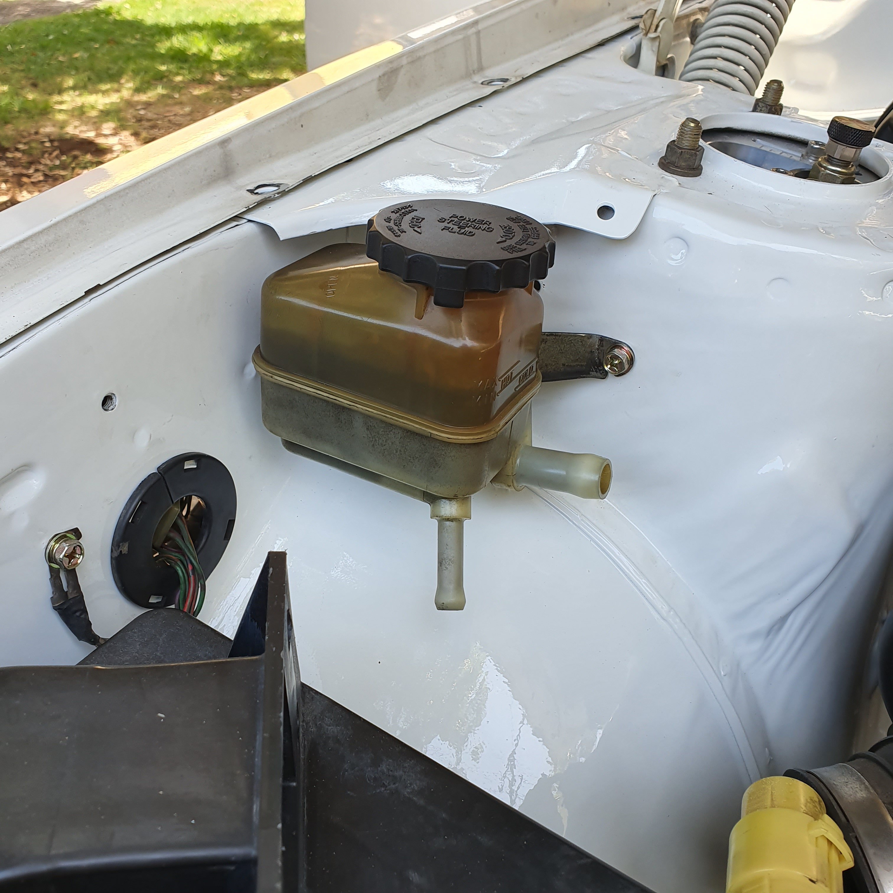
St191 caldina powersteering reservoir and bracket as 1gge are remote reservoir
1 point
-
If I owned a north island based bike, I could fly in fly out. The week before nats. Then when I flew home from nats, I could move in to a bachelor pad, on account of the dissolution of my partnership with her indoors......1 point
-
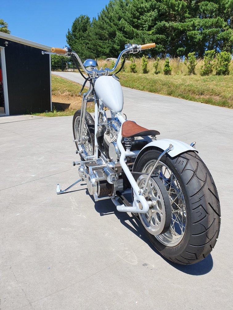
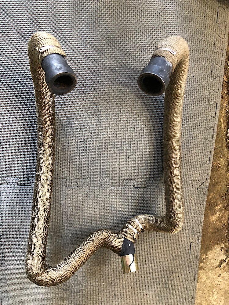
Originally was going to do twin supertraps each side but having them hugging the frame at the angle I wanted just wasn’t working for the chain side. So scratched that idea and went 2 into 1. Used 38mm mild steel donuts and U bends to shape the exhaust. Mig welded it all together, gave them a couple coats of header paint then wrapped them in titanium header wrap.
1 point
-
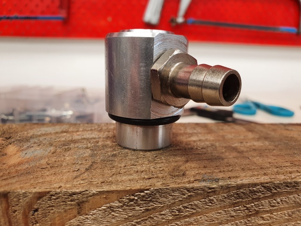
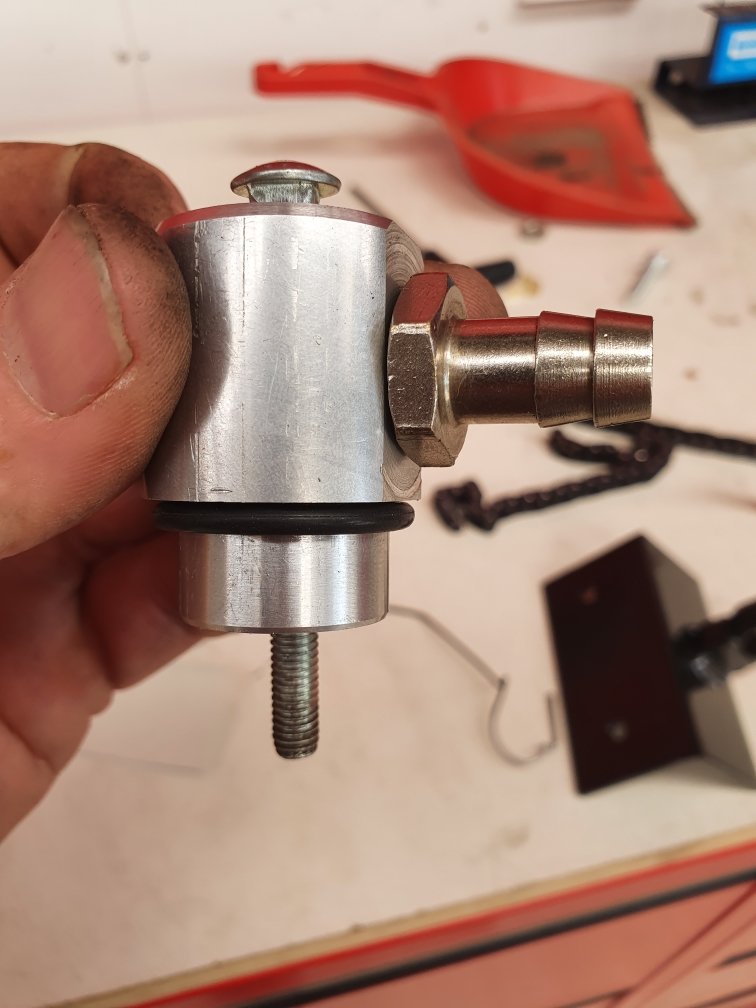
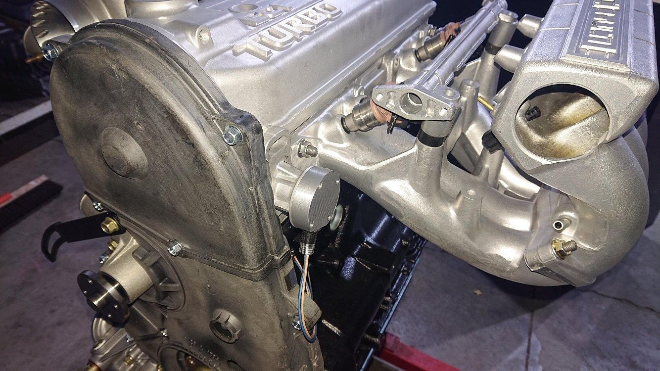
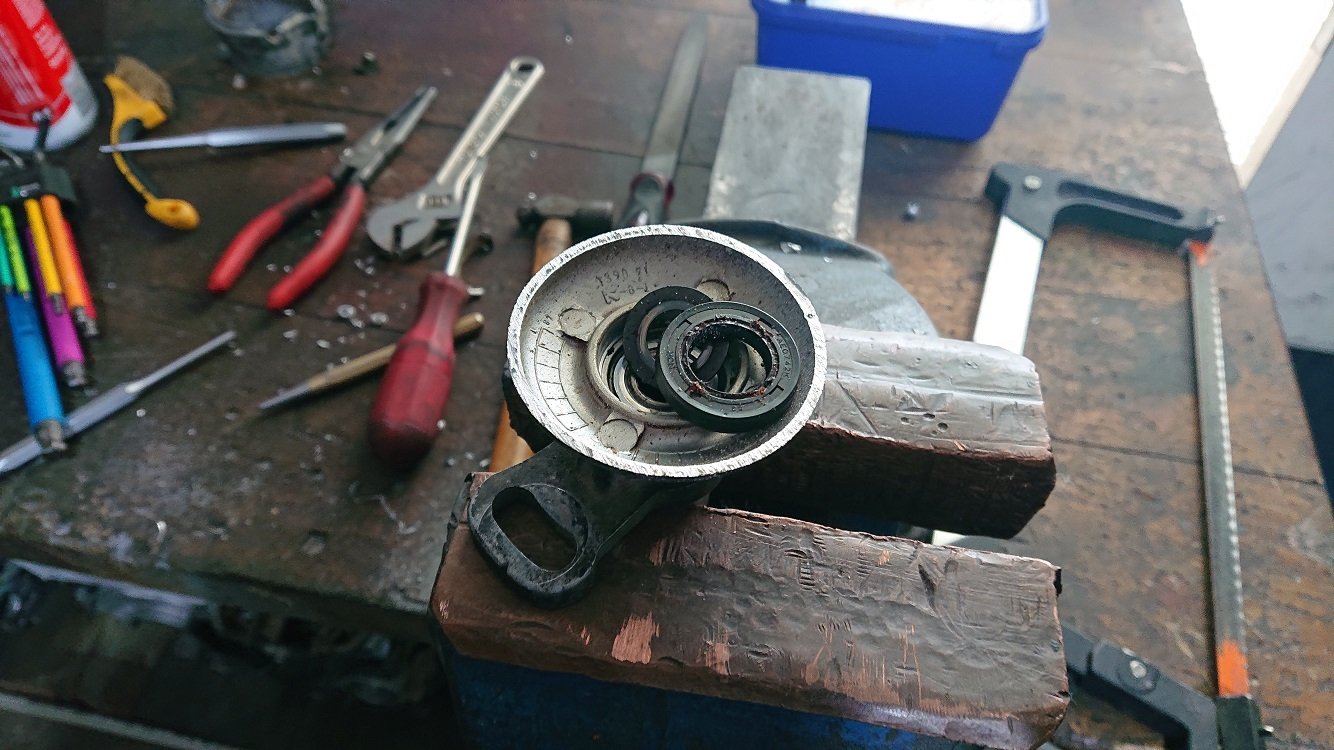
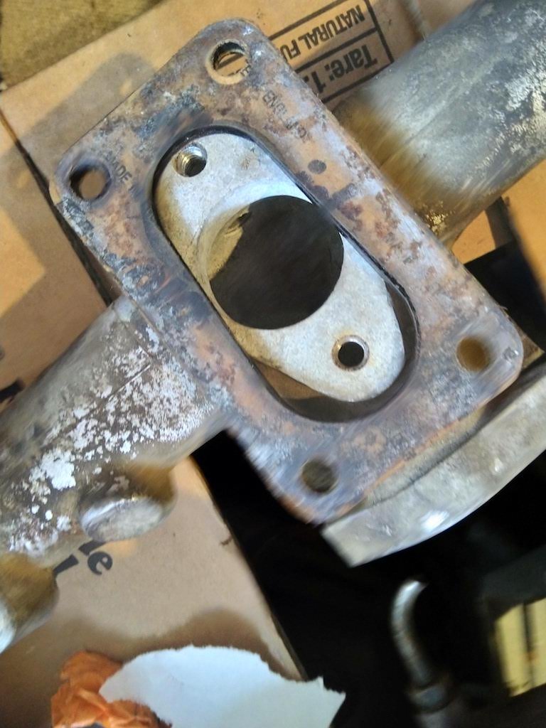
This is what was floating around the valley of my motor: The 3x little chunks were lose inside the valley under the inlet manifold. The larger "seal" was just flopping around on top, in the hole pictured in the above post. No wonder it was leaking oil eh! This part will replace all that shittyness. Its held down by a through bolt (this isn't the bolt I'll actually use, so stand down internet warriors). There's already a threaded hole for it in the block, left from the origonal down draft tube that's supposed to be there...very convenient, so that's what it will bolt down on and then the o-ring creates the seal.
1 point
-
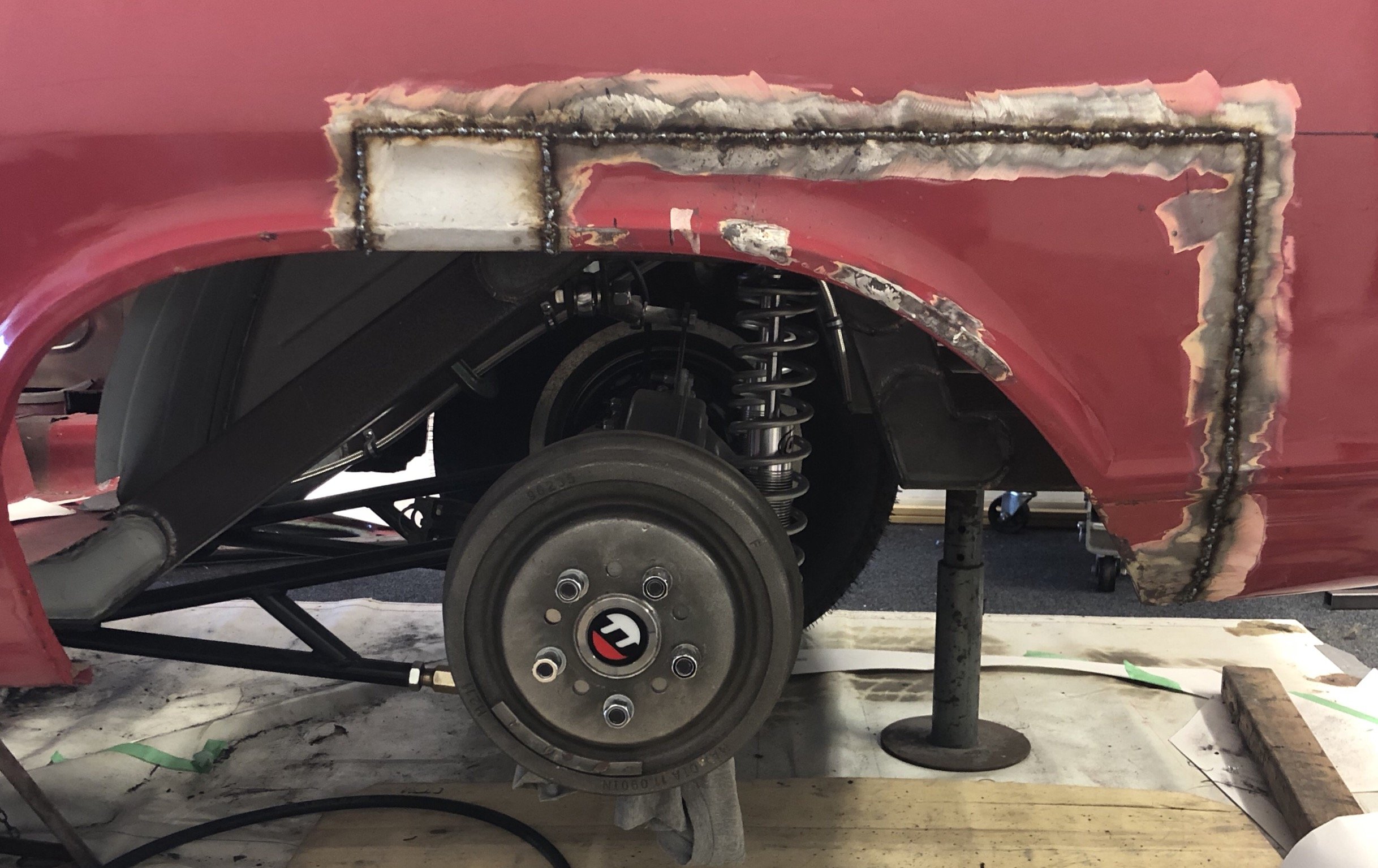
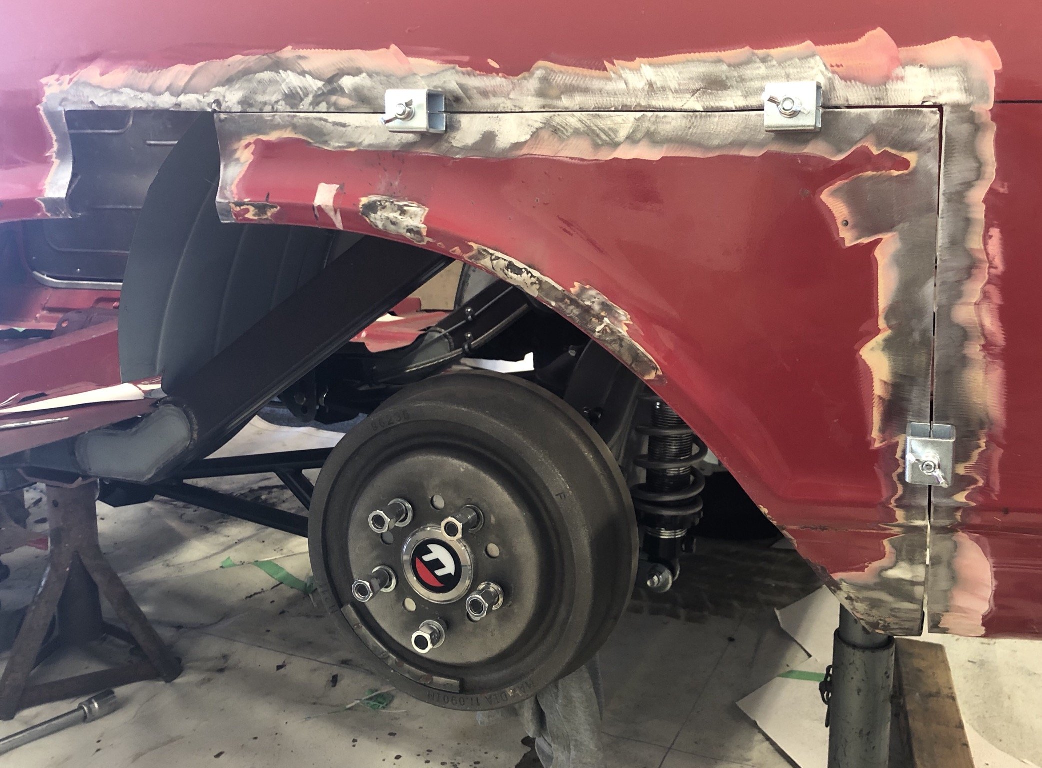
First sides all stitched up and came out pretty good..no warping. just need to flap disc it to see if there’s any little holes I’ve missed.
1 point
-
There’s no turning back now
1 point
-
sand, fill then prime again. i have the colour mixed for the top coat so ill be attempting to paint it red probably saturday. 2020-01-09_12-19-49 by sheepers, on Flickr 2020-01-09_06-20-37 by sheepers, on Flickr1 point
-
15th then? it being the 3rd Wednesday so staying true to tradition?1 point
-
I looked further into it, got a haynes manual and got excited. Measured up my mates bike in the UK. Came back to NZ and started building the housetruck/rotorising the Viva. That put an end to Imp stuff for ages. In the meantime a fella in Scotland called Clark Dawson ran with the idea and ended up with a successful conversion. He then went on to getting parts cast and machined and has since had many kits made up. I think he has passed that conversion onto another outfit. Its not cheap at around $2k and you have to wait until there's enough people wanting for them to do a run of kits. It really is about the most perfect engine for the Imp. Weighs about the same as the imp engine, lays flat, with the kit it just bolts up. starting with 90 bhp up to 125 depending on the bike you source. Wires in easy. Looks and sounds fantastic. I've been keeping a look out for a cheap bike but so far they've beyond what the moths in my wallet want to spend. Im still keen and would do my own adaptor parts , more just for the fun. I'll send you a link via facebook to the page you can join...1 point
-
This is nearly working. Lots has been done since ^^1 point
-
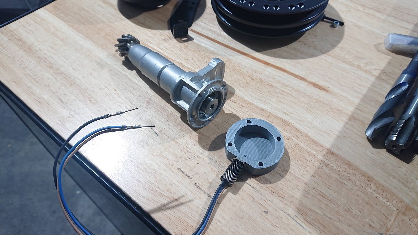
A couple more hours on the intake manifold side of this today, decided to tackle the cam trigger. I got hold of an old distributor from a carby one of these motors. It was missing pretty much everything, just a bare housing, shaft and advance weights still there. I attacked the shaft and housing with a hacksaw to get it down to just the bits I might need. I'm making this up as I go along, so I hope it works out ;-). What I'm trying to accomplish here is to mount a threaded hall sensor in such a way that it picks up a trigger signal once for every camshaft revolution. Ideally I'l love to mount something behind the cam wheel at the front, but there are no mounting points there, and although I could drill through into the head to make some, I'd enter a water gallery for sure and I don't like my chances of sealing that up afterwards. I thought about maybe picking up off the back of the cam via a custom mount that takes the place of the half moon seal, but there isn't a lot of room to work back there either. I also didn't like this idea in the end as the trigger disc would have to have a pretty small diameter, and as the trigger wheel you're reading gets smaller (so triggers are closer to the centerline of whatever is rotating) a small error in the point the trigger is detected can actually be a pretty large number of engine degrees. The dizzy rotates in line with the cam, so if I can make something tidy here, its about the best compromise I can think of. Looking at the cut apart dizzy, I liked the look of those four pads radially spaced around the housing, I figured I could clean it all up, drill and tap those for M4, and make a cap that attaches on and holds a threaded hall effect sensor. The shaft itself can then be tidied up, drilled and tapped for M6 to give a good mounting point for some sort of trigger wheel (with just one tooth :-). Some time on the lathe and drillpress later, as well as a quick 3dprint to prototype a cap (will either print the final one out of some material that can handle the jandle, or machine out out of aluminium), and I think it's going to work. Not as tidy a solution as I'd really like, and you need to be aware that if you ever remove and refit it, you'll need to reset the base timing most likely, but I think it'll work :-). The trigger disc can just be made out of a bent piece of steel, will make something tidy for it. There is a bit (I'd like more!) space to squeeze a coolant neck out next to it aswell.
1 point
-
1 point
-
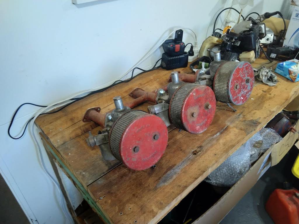
Been making some slow progress on this. Go the guards and front valance off and engine bay nearly stripped now. Just got to take the steering box and column out now. No nasty surprises so far which is nice. In more exciting news, I've got my hands on some triple carbs for it. Not sure what the condition of the SU's is like, but externally they look all good.
1 point
-
Well, hallelujah, real progress that actually looks like something, for once! The car is so small that the actual painting takes very little time. So, after months of slow stripping and prepping, all of a sudden it's starting to feel like it might actually be done one day. Next up is a coat or two of filler primer to sand back and get everything as straight and sharp as poss, then colour.1 point
-
This would have been in '85. It was from Oakura, white with 2 gears available on the column shift. Rust holes behind the back doors you could fit a hand into. We drove it back to Hawera around the mountain to avoid the popo with only 2nd and 4th gears. I heard the engine blew up shortly after I sold it. That was a 1600 crossflow that i put in with a floor change box, I didnt have many tools so I cut the hole for the gearstick with a cold chisel and a big hammer. The paint was terrible, I put more than 4 litres of bog into it along with some roofing iron to support things. I learnt how much I don't like painting things when the hours of what you thought were spectacular prep ended up with a sweet grapefruit finish. Hopefully I have learnt some things since then.1 point
-
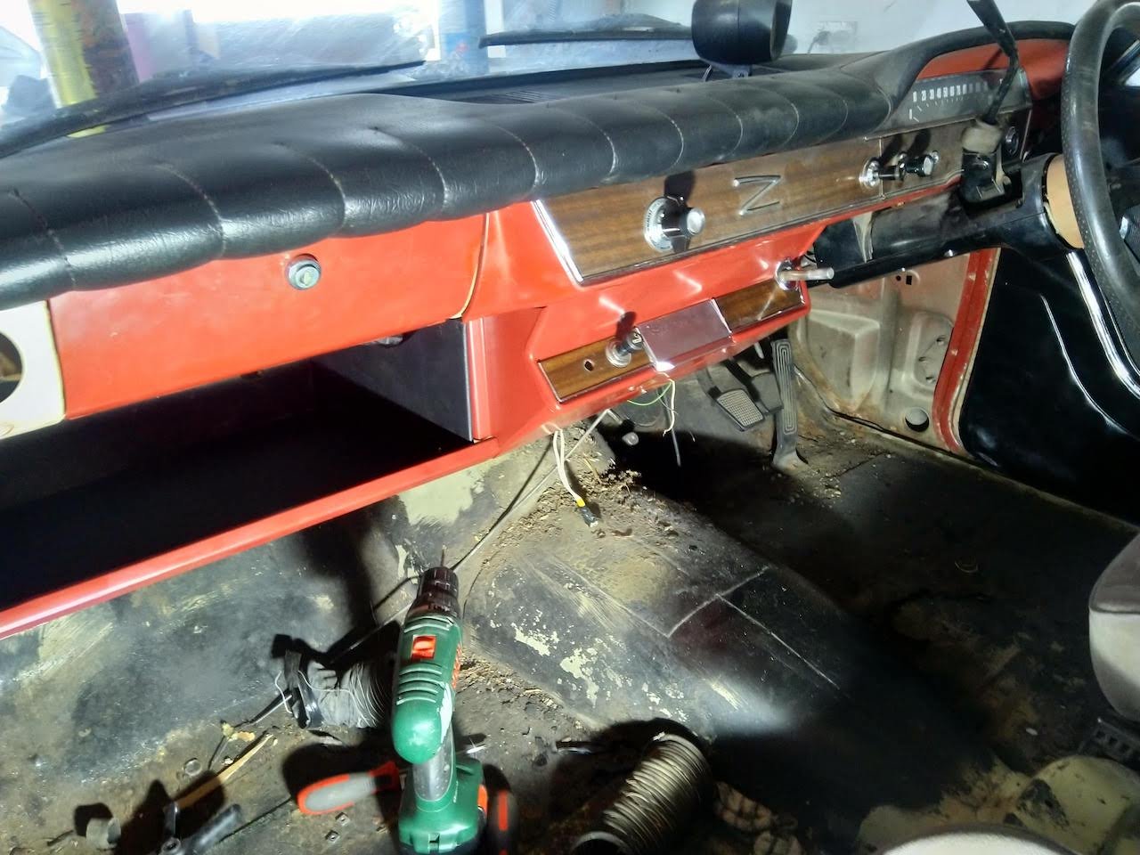
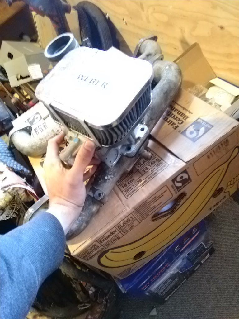
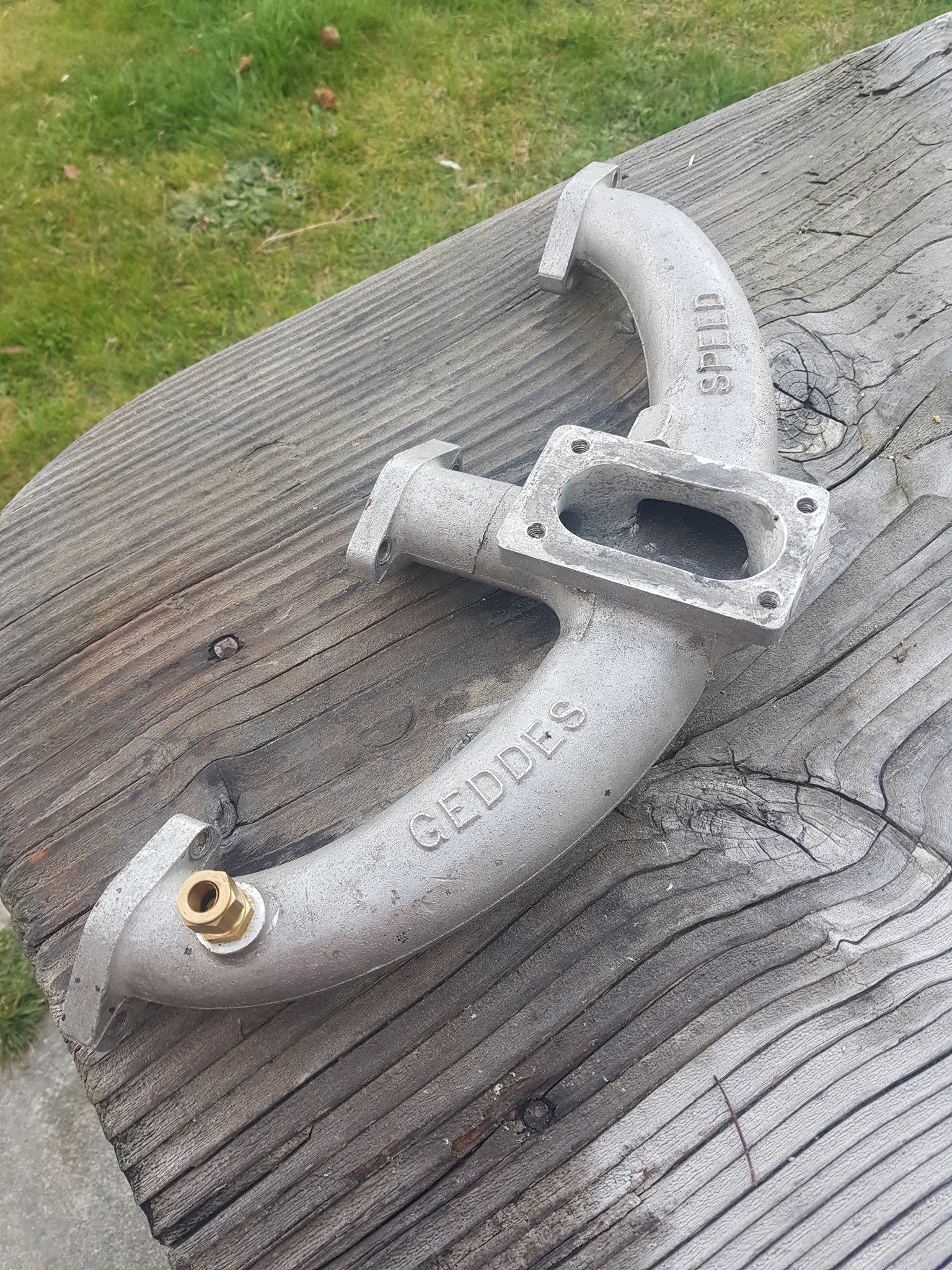
Got the dash all finished off, pretty happy with how it looks now. Got a colour matched rattle can and a can of matte clear. Looks fairly close to the original. Found someone on facebook who had adapted a factory manifold to suit a weber 32/36 carb, similar to a geddes speed one. I think I'll give it a crack, I've got a couple of spare manifolds so doesn't really matter if I screw one up. Plan is to cut off the raised mount, make a new carb flange out of 10-12mm Al plate, get that welded on then have a go at matching with a die grinder.
1 point
-
You're a lost cause, Phil.1 point
-
fitted the carpet and under lay, looks pretty sweet it wasn't the best fit and had to trim some pieces but I'm happy for the $ gave it a wash for the first time good to get all the dust and crap from sitting around for so long, took a few snaps while the sun was out was having an issue where it ran out of fuel couple of times and had me scratching my head for awhile, but discover the fuel tank isn't breathing and creating a vacuum, when i crack the fuel cap it lets the fuel flow again so I'm not sure if the original cap had some way of venting or if it was meant to have a breather somewhere in the tank lines. one of the next jobs is to have a crack at recovering the door cards in a similar red to the seat and make some new kick panels.
1 point


.jpeg.7dbde483b963e88ca5bb2c4549d1ecec.jpeg)


This leaderboard is set to Auckland/GMT+12:00