yoeddynz
-
Posts
19,462 -
Joined
-
Last visited
-
Days Won
158


yoeddynz's Achievements
Committed (5/5)
66.9k
Reputation
-
As a reminder of not what to do?
-
I've saved you a load of work with some of my thorough design knowledge and it's rather good.. ..and those silly outboards can fuck right off because my design includes a robust little EA flat four, inboard mounted.

-
Late reply sorry. I've tried all sorts of things as wondering if it was some how locked. It's got me stumped. Ideally need to find a complete total computer programming nerd local to me and challenge them.
-

Yoeddynzs 1965 Hillman Imp. Chasing Flappy whirrs
yoeddynz replied to yoeddynz's topic in Projects and Build Ups
Very small update. So whilst I have been making exhausts to create certain noises I have also been chasing other noises I don't want. First off though is a pic of exhaust version 3.0 with added 0.1 extensions... Pointing out at roughly 45 degrees and extended further these have so far seemed to have really improved the fumage issue. I'll have to do more driving with the window down to confirm. I still want to spend some time doing more tuning as well, smooth out the map and get rid of the really rich spikes sometimes seen. So the other noises I mentioned? Well for roughly the last couple of months I have noticed that after startup whilst in warming up and the idle is high there's a funny whirring sound coming from somewhere in the engine. It was hard to tell where when the car was sat on the ground. I'd look underneath and try my best to pinpoint it but it's tricky with all of the general mechanical sounds bouncing off the ground. I was thinking the only thing it might be was the chain drives for the oil pump having bedded creating a bit of slack on the free side and somehow whirring. The release bearing was also occasionally making a tinkling sound, or possibly its actually the 3 bearings I had fitted in my 'thrust bearing 2000' assembly that resides between the back plate and the flywheel. Oh and the new exhaust has a tiny rattle on one side. Only noticeable if I smack the box up on that side (a quick lesson was learned not to do this when its searing hot) and I suspect its actually the tube the runs through the flexi joint just touching. Hopefully I can rectify it by adjusting the bobbin height on that side. But this whirring sound? It goes away somewhat when the idle drops as the engine warms up and I cant hear over the exhaust from then on. So this morning I started the car up, moved it from its garage and out into the sunshine. I let it warm up. Then moved it inside and onto the hoist. Once up in the air I started the car (using my go go gadget arms) and listened from underneath. Being fairly warm the sound was barely audible until I reached up with my arm to the throttle body and gave the engine a rev. Bingo- there it is! Its in the cambelt cover! Its a flappy whirr. A rubbing flappy whirr. I let the engine cool down, went for a pushbike ride and then this evening it was off with the cover, which luckily is super easy to remove once the alternator pulley is removed from the crank. Zoom in.. That bottom belt run on the left was a bit loose. Not terribly but certainly a bit more than the specified 5-7mm Honda advise. When the engine is cold its free to move that amount. I presume as it warms up it gets a touch tighter (boxxer engines 'grow' a little in width as they warm) The manual states that if the belts are too loose they can flap against the cover. Too tight and they whine. I could see where its been rubbing on the cover.. I have now tightened both belts just a smidge. Its a bit tricky to exactly measure 5-7mm but they seem about right. Cover back on and I'll test it tomorrow. (I'm not keen on filling the workshop up with warm up fumes tonight when our bedroom door is about in line with the roof of the Imp) Also to note. This morning was an especially cold 'late summer' start to the day of only 2 degrees. After I started the car later in the morning and moved it out (around 12 degrees then) I opened the engine bay lid for a look while it was warming up. I soon spotted one of the injector rail hose clips at the front was leaking. I promptly tightened it up and leak be gone. I can only presume the rubber hoses had shrunk ever so slightly in the cold night and allowed the fuel at 40 psi to weep past. I checked all the other fuel line hose clips in the engine bay and one other was slightly loose. I must check the ones in the frunk too!- 120 replies
-
- 31
-

-
I'm going to have to send a strongly worded email to Billy G.
-
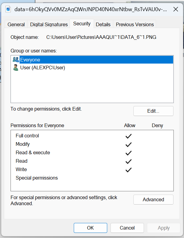
speaking of files. How the fuck do I remove this image/file/aliens from my laptop. Its just saved in one of my photo albums. Here's a screenshot of it.. Here's some screenshots of its properties.. Damned if I can erase it from the laptop? Its like its burned in.
-
200 kgs heavier than my Imp though! - yeah bigger car and engine etc but I don't think your car is that tinny. Just the way things were before they got huge and fat. I love to corner weight nine. Must ask the friend who had the same scales I had used to with my viva with the v6 (which was a simar weight to your car iirc)
-
Just for the record. I put the battery in the front of my Imp because it's about the weight of one standard bag of 'handling improver' concrete.
-
Is that a Mugen nest?
-
I'm loving that Revanced you put me onto - works a treat. For the laptop adblocker is still working fine too.
-
IIRC a decent length of rubber hose feeding the rails can be quite an effective damper.
-
A bit presumptive thinking that all herb growers are rotary fan bois. Some of them have probably matured to more exotic tastes 🧑🎓
-
Discuss here about Yoeddynz's little Imp project...
yoeddynz replied to yoeddynz's topic in Project Discussion
It's a very slippery hole you're heading into. -
Discuss here about Yoeddynz's little Imp project...
yoeddynz replied to yoeddynz's topic in Project Discussion
Would you two just please clam up. -
Discuss here about Yoeddynz's little Imp project...
yoeddynz replied to yoeddynz's topic in Project Discussion
Perfectly weighted and tuned to replicate the clatter of an aircooled engine.