
Leaderboard


Popular Content
Showing content with the highest reputation on 02/05/24 in all areas
-
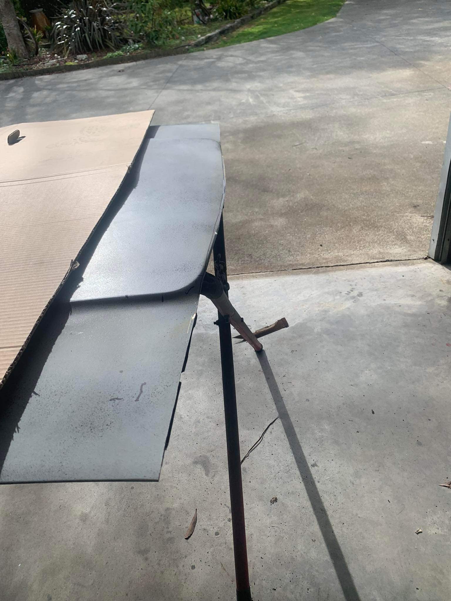
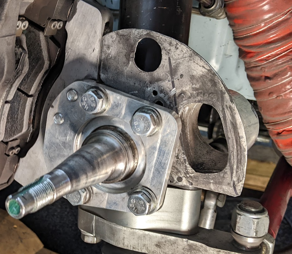
The correct tie rod end arrived a couple of days ago thankfully before the wof grace period ran out; And so this just happened; And I was greeted by a complementary bit of even leakier wedgieness which was an irresistible photo op; So fucking excited.19 points
-
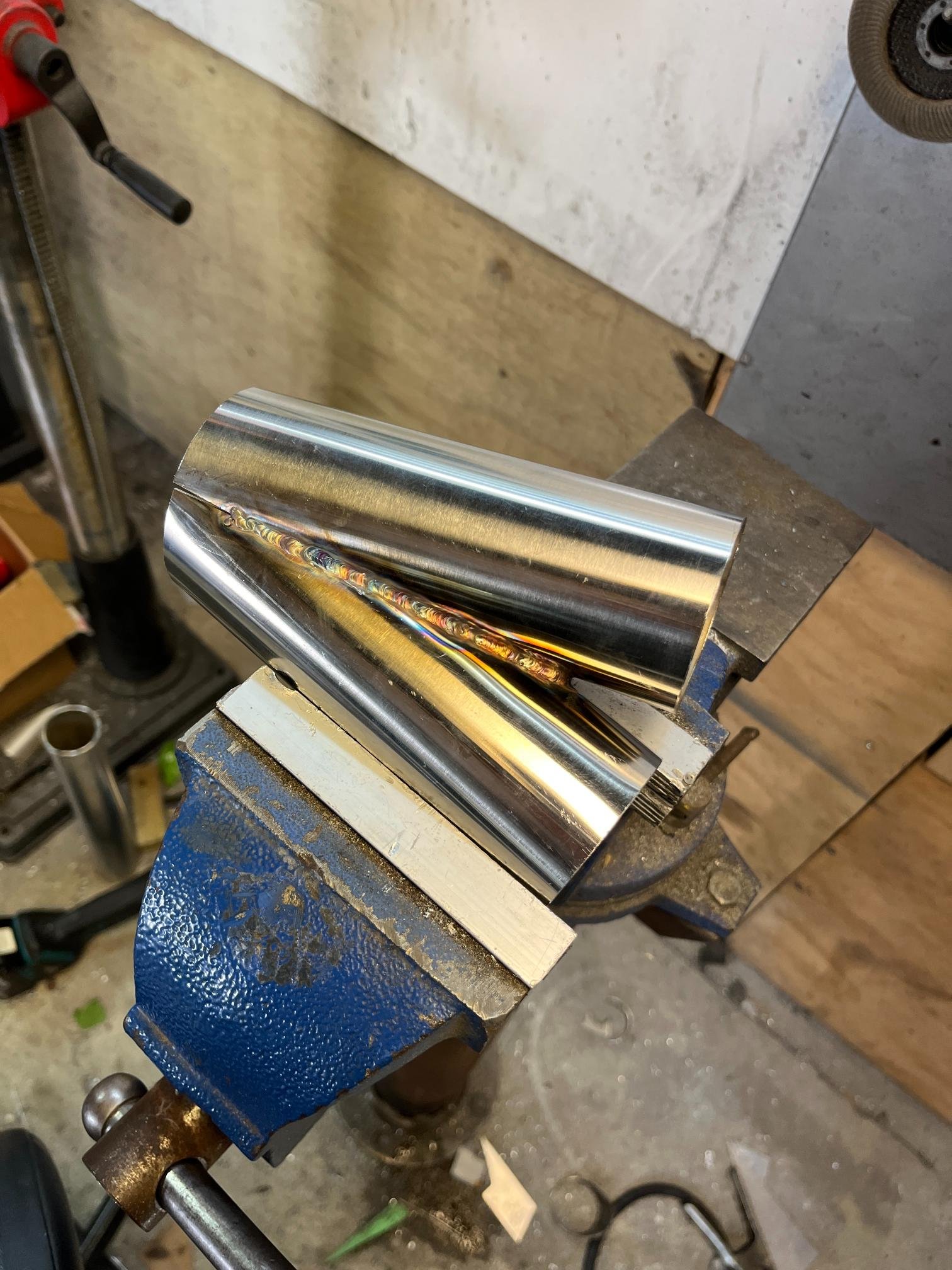
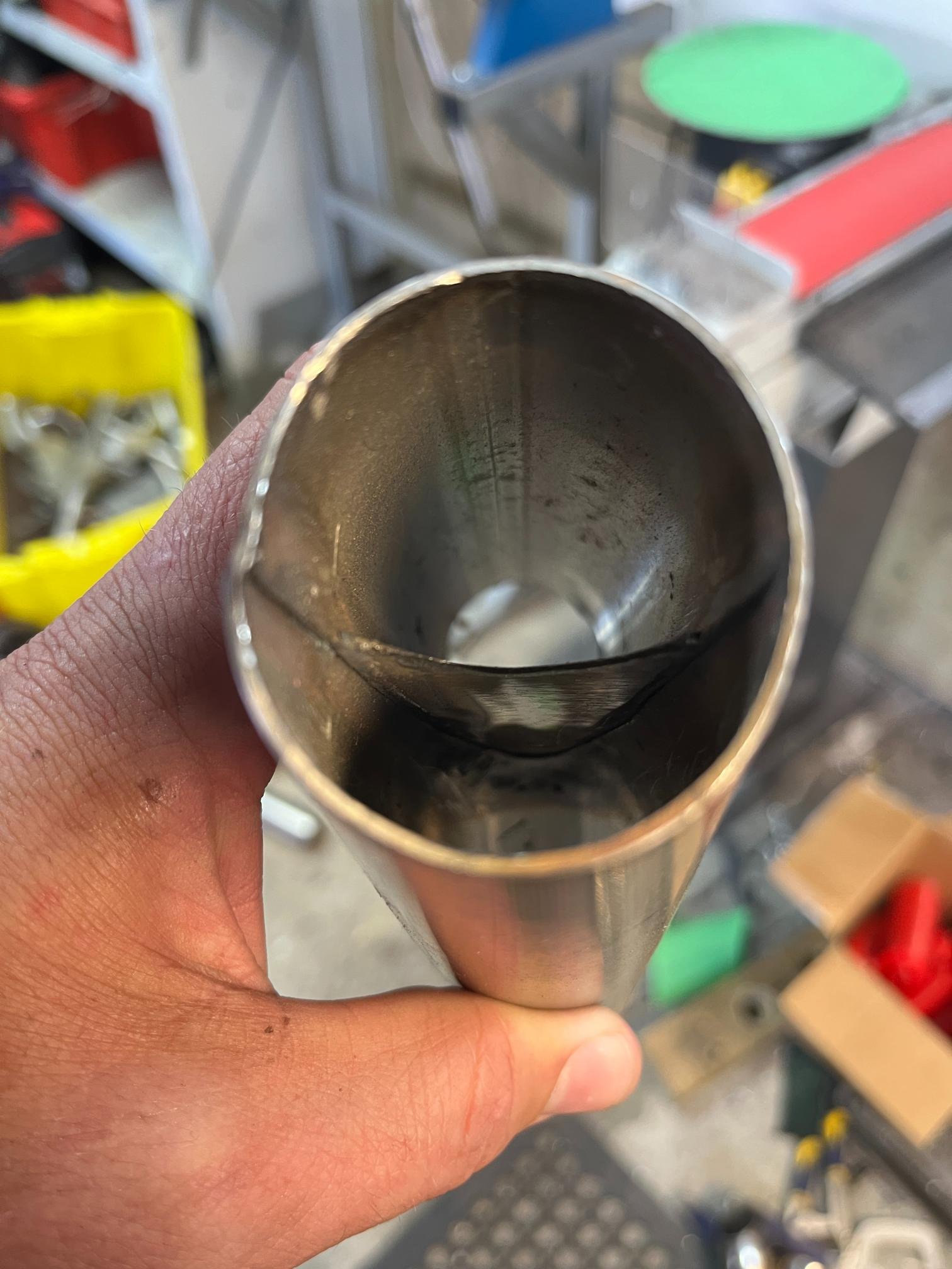
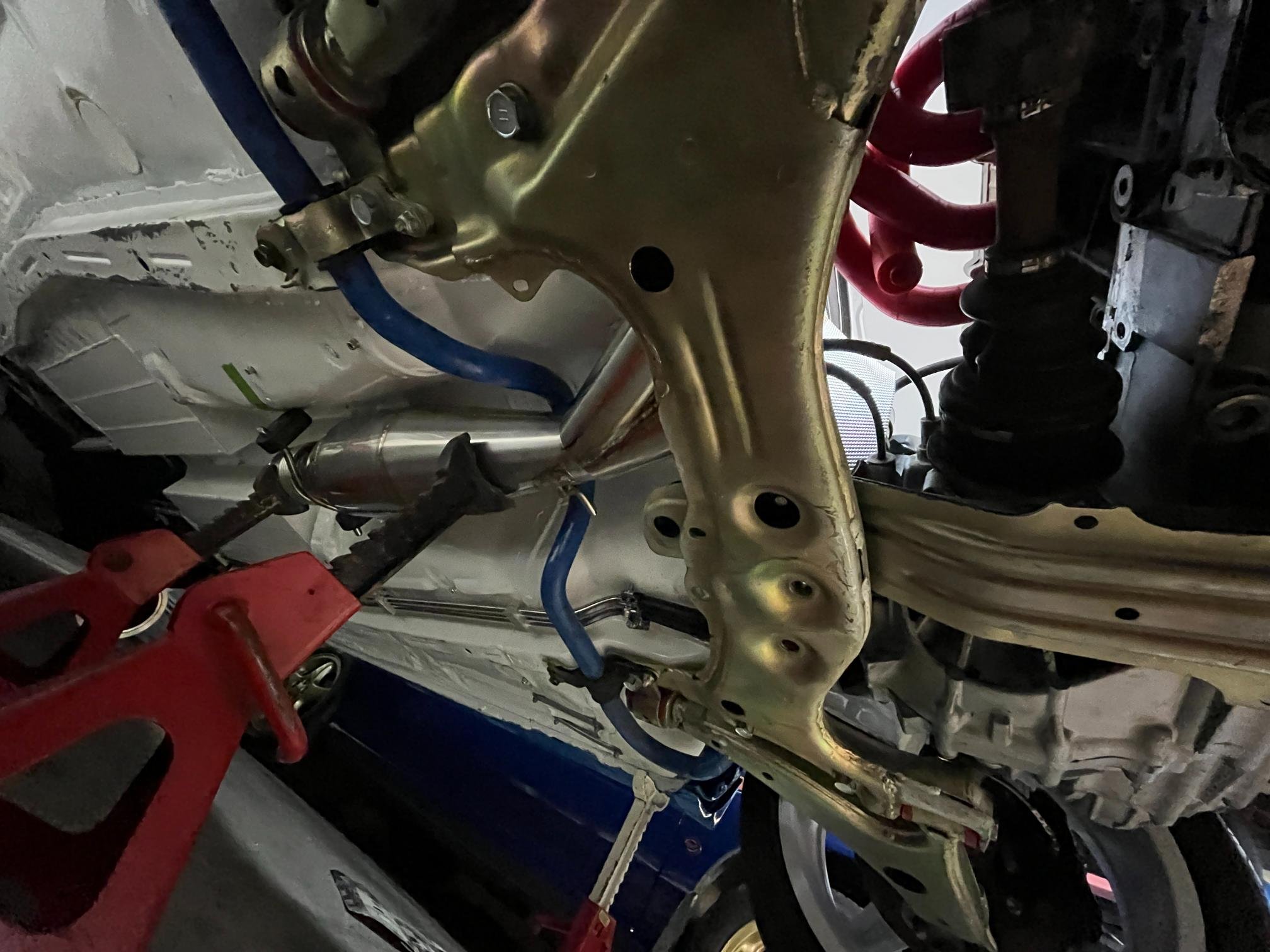
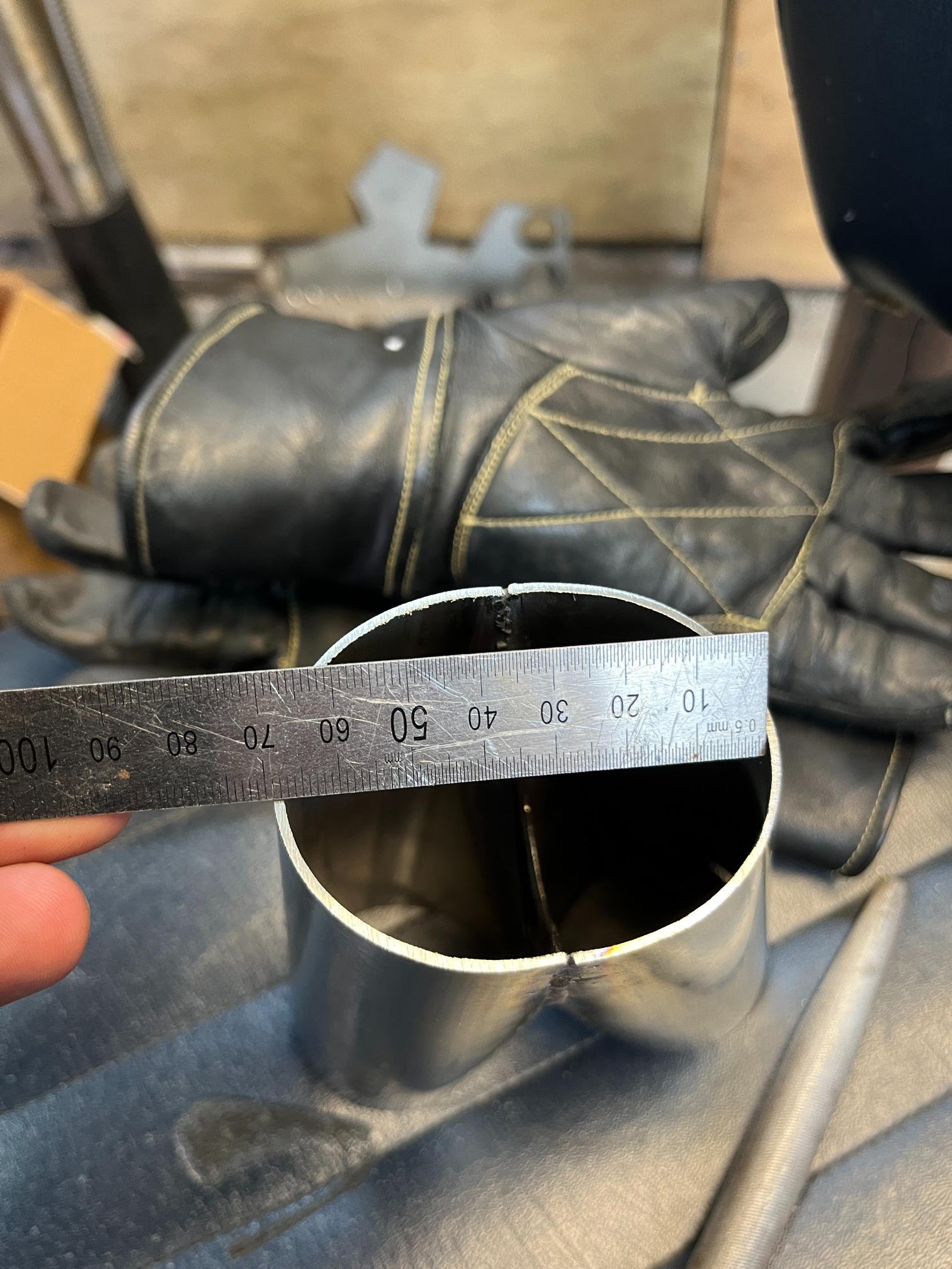
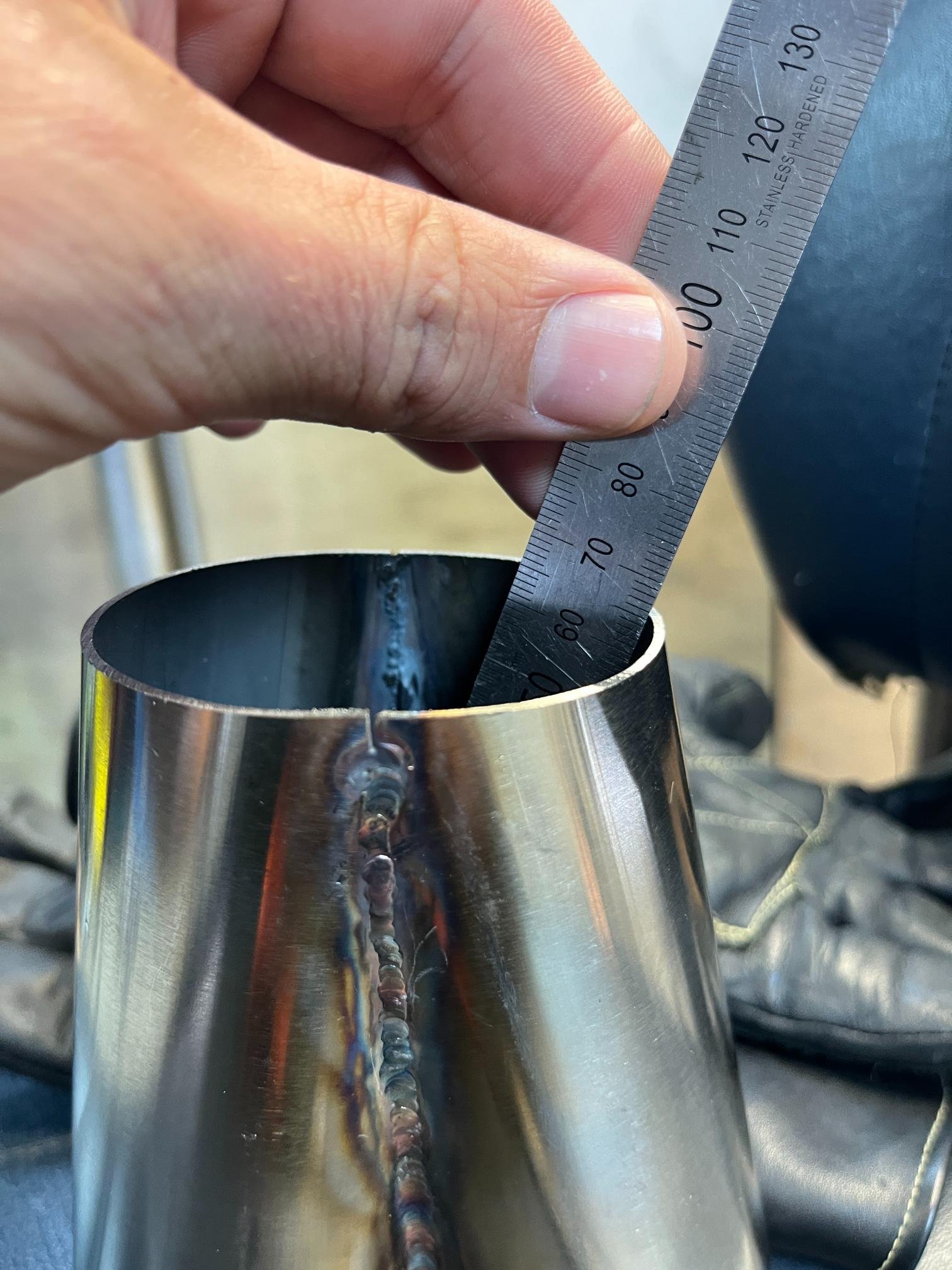
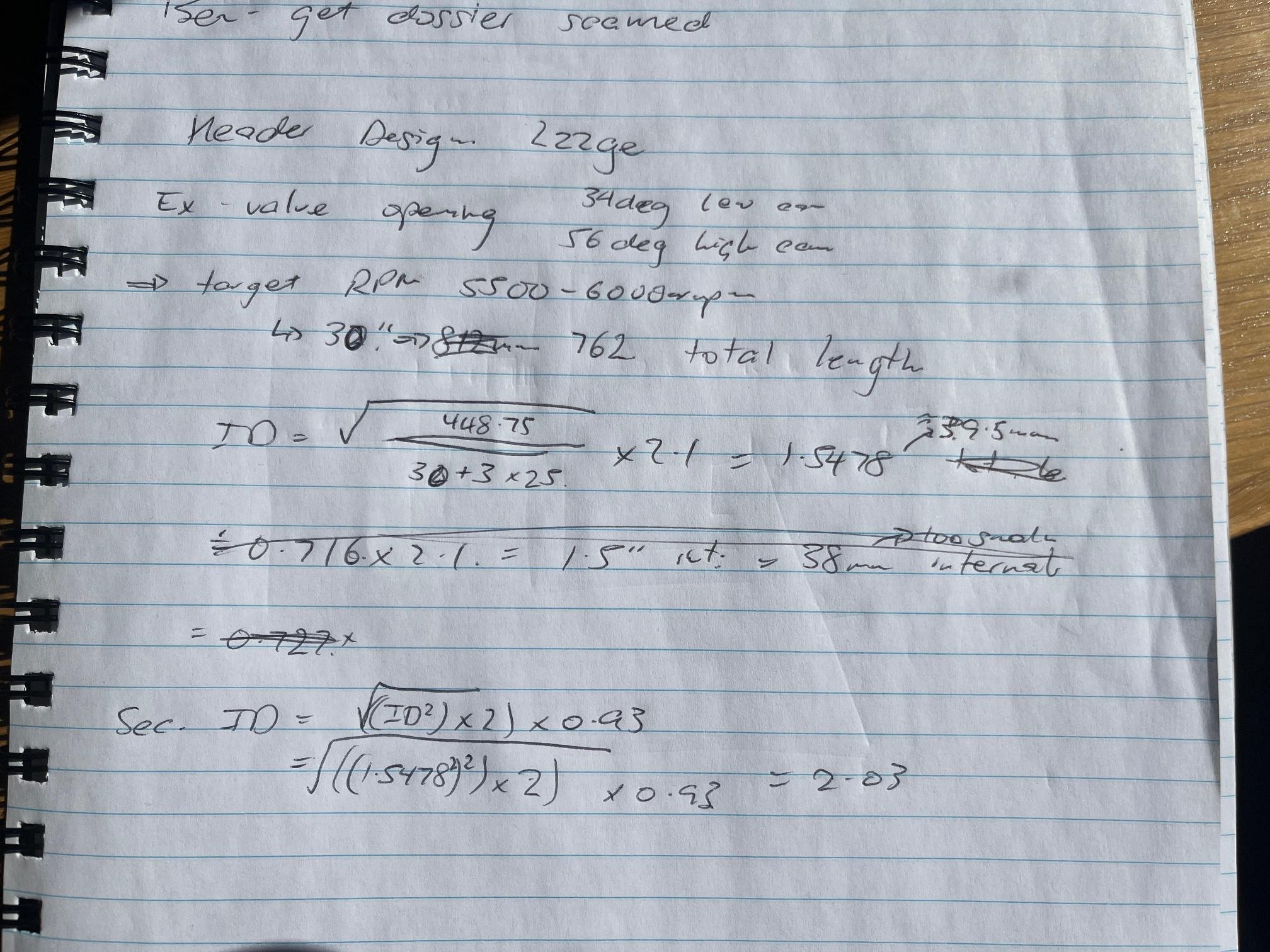
Not much progress to report but lots of technical stuff going on with the design/fab of my headers, so sorry but this will be a nerdy post.. not claiming to be an expert, just figuring out how to make stuff work.. So here's my scratching for re-checking my length. Unfortunately I need to run 4-2-1 header as I can't fit 4x runners under the steering rack. The expansion chamber clashes with the swaybar (wasn't in the car when I mounted it argh!), meaning I've needed to push it back another 100mm. I'll need to incorporate the slip joins into the '2' section (because bottom section will be permanently attached to exp. chamber) as this is the easiest place to get the runners parallel where they'll slow into place.. This means my 9" secondaries are going to look more like 12", which by keeping overall length the same, will mean my primaries are getting close to 15-16" (which is the minimum as I understand it). In summary its complicated..... With restrictions in tube sizes available (above calcs is inches ID), I've had to go for 44OD primaries (works out well as is the same size as exhaust port) and 57OD secondaries. Secondaries in particular will be a little larger than optimum considering it's only a 30" long pipe, so it will likely favour higher RPM's. As long its making solid power from 5-6krpm I'll be happy. 2zz's have a massive torque hole at 4krpm so I'll be bringing the high cam in as soon as possible. Might also push me to add a big cam sooner rather than later.. Found this super interesting paper on the development of the 2zzge. Pretty much says they designed this awesome high-revving engine and then proceeded to put a terrible exhaust manifold on it to reduce noise emissions and wasted all the hard work they put into the head etc. https://www.lotustalk.com/attachments/toyota2zz-ge-technical-data-pdf.1297134/ For the header design, I'm following the theory laid out in Graham Bell's Four stroke performance tuning book. Main examples are based on 2L touring car engines, which is pretty comparable to what I'm doing (12:1 comp, itbs & 9000rpm). All my sizing/calcs are firmly in what he defines as purely 'racecar' realm... I also think engine & ecu technology has moved on since early 00's which has proven you can get away with a lot bigger tubes than the 'old' rules of thumb. I'm using an adaption of a venturi collector design with a centre divider plate. Apparently the venturi and divider plate should be equal-sided triangle 1/2" bigger than the primary tube. Nailed the fabrication on the secondaries in particular which I'm proud of. Will be interesting to see if these work as it does essentially create 2x venturi effects in the same collector - 1 where the pipes join, then a second as it expands to secondary. Who knows if this will work as intended? So this is my crossmember conundrum... I ended up needing a small bend between the collector and expansion chamber which is another compromise.. Primaries are roughed-out in Kinex blocks. These are a bit of a spaghetti junction as the 2-3 cylinder runners need to go the furthest so need to take the 'under' route. No doubt these will be refined a few more times as I confirm the position of the secondaries. I plan on tacking secondaries up to slip join, then start back at the top and work my way down. Wish me luck!! All this learning has taught me is everything is a small compromise when it won't fit in the car. Exactly how the power band will work out is yet to be seen, I won't be surprised if I end up making a few variations as I test these.. just got to keep putting in the effort and one day this damn car will be finished!
 9 points
 -
In the early R06A engines like in my Alto, the crank thrust bearing issue is well known. I decided to preemptively replace mine. From 2016 to around 2019, when they changed to the Type 2 cars (which basically just incorporated all the changes made through the production of the Type 1 cars), the crank thrust bearings have an issue where the metal was too soft, and the bearings could wear prematurely. The issue is so prevalent that Suzuki Japan issued a warranty extension/recall in Japan for it, extending the warranty to 10 years/200,000km. Unfortunately this doesn't carry over to imports in NZ, and I've also seen reports that getting Suzuki to actually cover the work means waiting until the engine is basically toast from the bearings failing. Their "solution" is to replace the crank, block and bearings; a full rebuild. My friend Tom @tomble with the blue HA36S, who unfortunately had an engine whoopsie on track earlier in the year, happened to order a spare pair of thrust bearings with his order of bits to rebuild his engine. Knowing my car was in the VIN range of affected cars, I obtained the bearings from him, intending to replace them before things went bad. I was doing this preventitively, not because I knew mine were stuffed, keep that in mind. I had been ignoring the niggle at the back of my mind knowing my car could be affected by it. The usual indication that the bearings are starting to fail is a knocking when engaging and disengaging the clutch, as the force of the clutch causes the crank to move due to excessive runout. My car was what I would consider quiet, for what it is. No noises out of the ordinary, but the other day when I drove the car to work my Android Auto was a bit slow to connect and the first couple of minutes of my drive had no music... and what happens when there is no music, you hear EVERYTHING. At one point, I thought I heard a slight tapping when coming on and off the clutch in traffic. It was quiet, and I couldn't be sure I wasn't just hearing things, my car does buzz and vibrate a bit at low RPM due to the inserts in the rear mount... That day after work I picked the bearings up from Tom. I couldn't risk it. Last night, after work, I put the car up on stands and set about replacing the bearings. Unfortunately they are inside the engine, so not a "simple" task, but overall very doable in a garage on stands, with standard tools (with the exception of a torque wrench and angle gauge, both of which are easy to obtain). The biggest issue is that the sump needs to be removed. To do so, the front pipe of the exhaust needs to also be removed, so there is space for the sump. My bolts were a bit rusty, so with a lack of fire-making abilities, I aimed the heat gun at them on full blast and got them as hot as I could (pretty hot, really). With a crack, the bolts came free. I completely removed it, but I guess you could probably just drop it down and leave it hanging if your rear bolts were unable to be removed I also drained the oil and removed the filter. I did this with an engine that had sat overnight, so as much oil would be in the sump as possible, so I wouldn't have it dripping on me when the sump was off. Next, I removed all the sump bolts and tried to get the sump off. The sump is sealed on with goop, and I battled for a very long time trying to break the seal. In the end, and I wouldn't recommend it if you have other options, I used a claw hammer to pry it free. It worked well with no damage, but you could easily break the sump if you aren't careful. There were two points on the front edge of the sump that were perfect to pry from With the sump off, I had access to the guts. It was very oily, so photos will be limited, but I removed the cap in question (second from the flywheel). With the cap removed you can see the bearings. Thankfully both of mine were still in place; when they get bad one, or both, can slip out and drop into the sump leaving the crank free to move back and forth. The bearings are curved and wrap around the top of the crank, one on each side of the main bearing cap. Using a pick to carefully push on the end of the bearing, you rotate the bearing around the crank so you can slide it out Well, it appears I was on borrowed time This is what the bearings should look like; the old ones are the inside pair There was no sign of any metal in the oil, or in the bottom of the sump, so I guess it's just been slowly grinding itself away over 100,000km. The new bearings (and the "good" old bearing) measure 2.5mm, the bad bearing? It's lost almost half a mm of metal You can tell if they are the original bearings (or at least not countermeasure parts), as the markings on the back will be different to the new countermeasure parts Old New Thankfully the crank bearing itself looked great, plenty more track days left in it The crank also appeared to be in good shape. The "bad" side had some slight ridges in it, but was smooth and still looked polished (some looked really chewed up when the bearing failed) I cleaned and lubricated the new bearings, slipped them into place on the crank, and reinstalled the bearing cap. Of note, was that before I removed the old bearings I could move the crank back and forth in the block by hand a small but noticeable amount. Now, I can't. The bolts are stretch bolts, which means they stretch when torqued correctly. Normally you would consider them one-time use, and replace them, but since I would be waiting over a month for a pair of new bolts from Japan, I looked for an alternative. According to the workshop manual, there is a spec that allows the bolts to be reused. You measure the thickness of the bolt at two specific places along its length; A, where the bolt would thin when stretched, and B, where the bolt should be original thickness. Subtract C from D, and that leaves you with a value that needs to be less than the 0.12mm limit. My calipers wont be amazingly accurate, they're ancient and weren't that expensive in the first place, but the main thing is that regardless of what the reading is, the value still needs to be consistent and less than 0.12mm. Because I didn't want to be left with no bolts that are in reusable tolerance once I pull the bearing cap off, if mine were over tolerance, Tom was kind enough to supply me with his old bearing bolts, since he used all new ones in his rebuild. I went through every bolt and measured them All of them were within tolerance, some more so than others, so I picked the three best ones and knew I could at least rely on them if mine were no good. I checked the two bolts from my engine, and one was 0.10mm, which is closer to the limit than I liked, so I swapped that for one of Tom's bolts and reused the other. Using my torque wrench and angle gauge I started torquing the bolts up. The spec is 30nm to seat the cap/bearing, undo it to zero, and then 20nm, before turning to 45 degrees and then a further 50 degrees. Both bolts torqued up fine, and the first one went to the two angles fine. Unfortunately when doing the first 45 degree angle on the second bolt the little lever that holds the angle gauge in place slipped, so I lost the accuracy of how far I had gone. I ended up removing this bolt and replacing it with another of Tom's bolts, which went fine this time. The sump was pretty clean after draining the left over oil out of it, so I scraped all the old sealant off and cleaned the inside with brake clean I then cleaned the sealing surface on the engine block, which is super fun upside down under the car. Permatex Ultimate Grey seemed to be a good replacement for the Threebond called for in the manual, so I slathered some of that on the sump and fitted it to the engine The bolts need to be fitted in a crisscross pattern from inside out, and were the perfect chance to use my little 1/4" torque wrench as their torque is quite low. The sealant needs overnight to cure, so I finished by installing the exhaust front pipe I wanted to make it as obvious as possible that the engine had no oil in it overnight Today after work, the sealant was cured, so I filled the engine with oil and fired it up. After a quick check that nothing was leaking, everything looked and sounded fine. It appears I dodged a bullet this time. I took the car for a drive, and it was noticeably quieter. I didn't think it was particularly loud beforehand, but there is less "mechanical" noise from the engine now. The two main noises that seem to be gone are the knocking/clunking when I back up my driveway from a stop when cold. I attributed this to the gearbox, as I had to slip the clutch a bit and it wasn't too happy doing it. Now that noise appears to be gone. The other noise was at high RPM, off boost, particularly when decelerating, the car would have a kind of buzzy tapping noise. It wasn't a bad noise, but it was there. This also seems to be gone. Over all the whole engine just seems quieter. I guess the bearing failure was more obvious than I thought. It's a good timely reminder that anyone with a Type 1 Alto (Works, RS, NA or Lapin), Wagon R, Hustler, or Jimny with the R06A engine is on borrowed time with their bearings unless they have been changed. Some of them go fine for many thousands of KM, and some don't last to 50,000km. My car has had a very hard life, and at 100,000km the bearings were stuffed and probably had one more trackday in them before it fell to bits. I'm very happy to know they have been done now, and extremely relieved to have caught that before it wore further and grenaded the engine.8 points
-
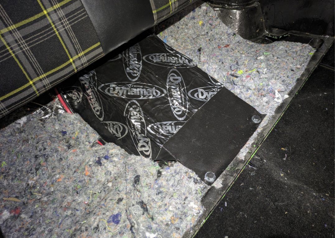
Woops. How'd that fall in there
6 points
-
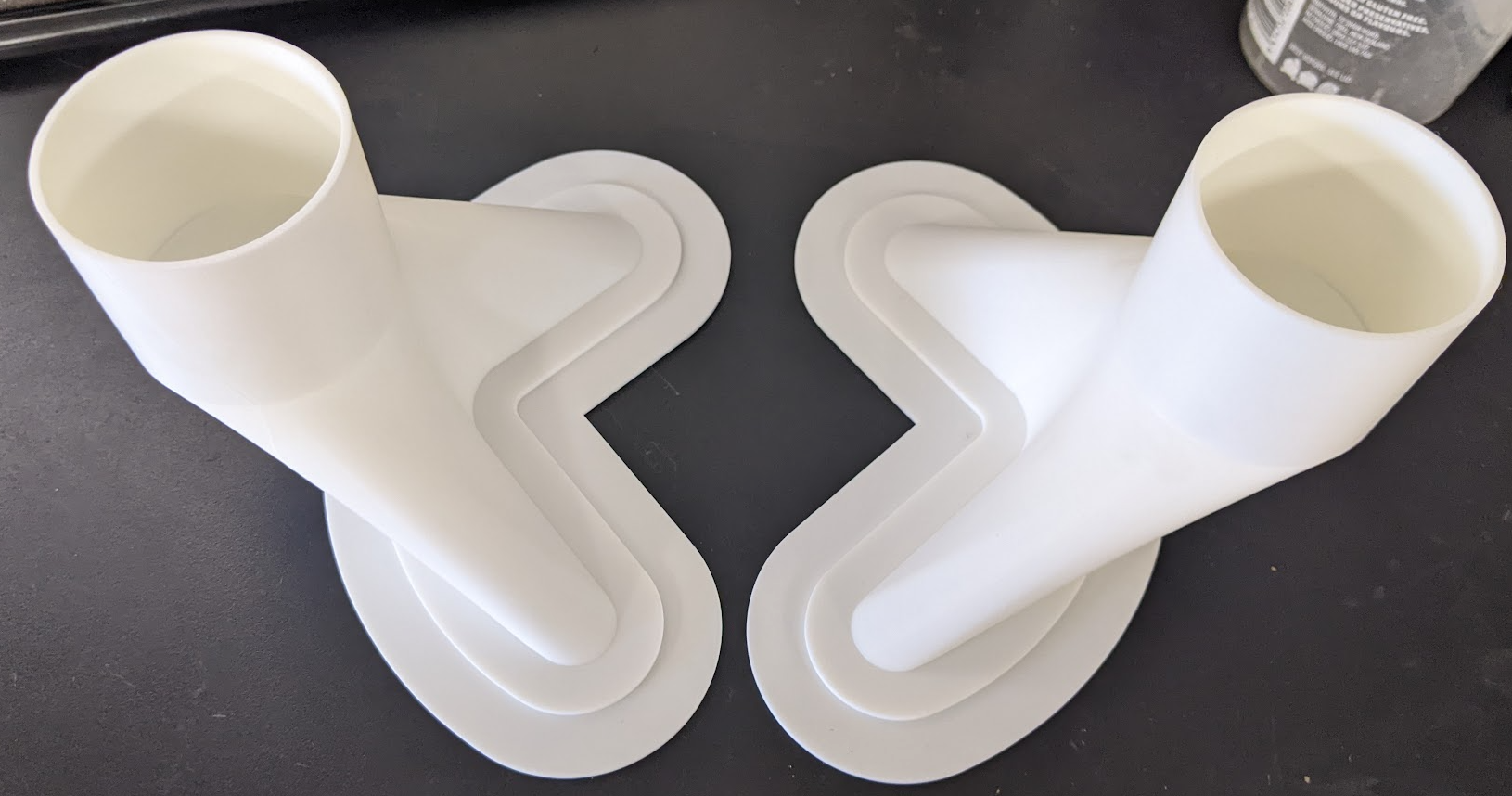
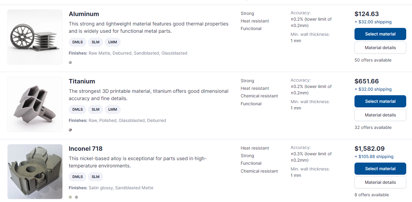
So after some reflection on this, I decided to make my life easier by going for 2.5", while I could have fitted 3" in, it just wasn't worth the effort at the moment. This allowed me to thicken up the outer edge of the plate, and move the air more inwards which is better. So plate ends up as this. For the ducts themselves, trying to get aluminium around them was proving too difficult for my skills, there was a couple of compound curves making life really difficult, even when I altered the ducting to be as simple as possible. I looked at casting but they would have been minimum thickness of 4mm and $1000 odd. I got a quote for 3d printing them in metal from https://craftcloud3d.com/ (min thickness 1mm) Actually not to badly priced $262nzd delivered for the 2 of them (in ali). But the current plan is to take these moulds in PLA and just wrap them in fibreglass, then melt the moulds out (found a friend willing to try it).
5 points
-
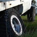
Aren't they just the cutest little wheels. So glad my fancy brakes fit. with half a gnat's foreskin to spare. I'm fairly sure they are 'straya contessa "minilites". 10" X 5"
4 points
-
Couldn't wait changed an old map I used at drag day then tweaked the injector flowrate using an online calculator. Measured in Ms/gram very confusing for me.... Flashed a good Bin file in then flashed the Calibration on top and bugger me it fired straight up! Let it run for 30 seconds that'll do it's really loud! Don't want to piss neighbours off after dark local pukekos were losing their shit. And im unsure if my turbo was getting oil so will confirm tmrw then do a video after checking if anything is resting on exhaust. Fuck yeah!!3 points
-
Remember it's a Fiat.3 points
-
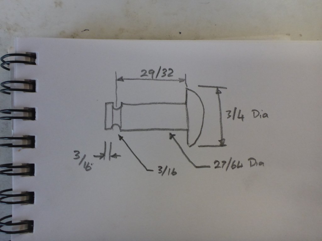
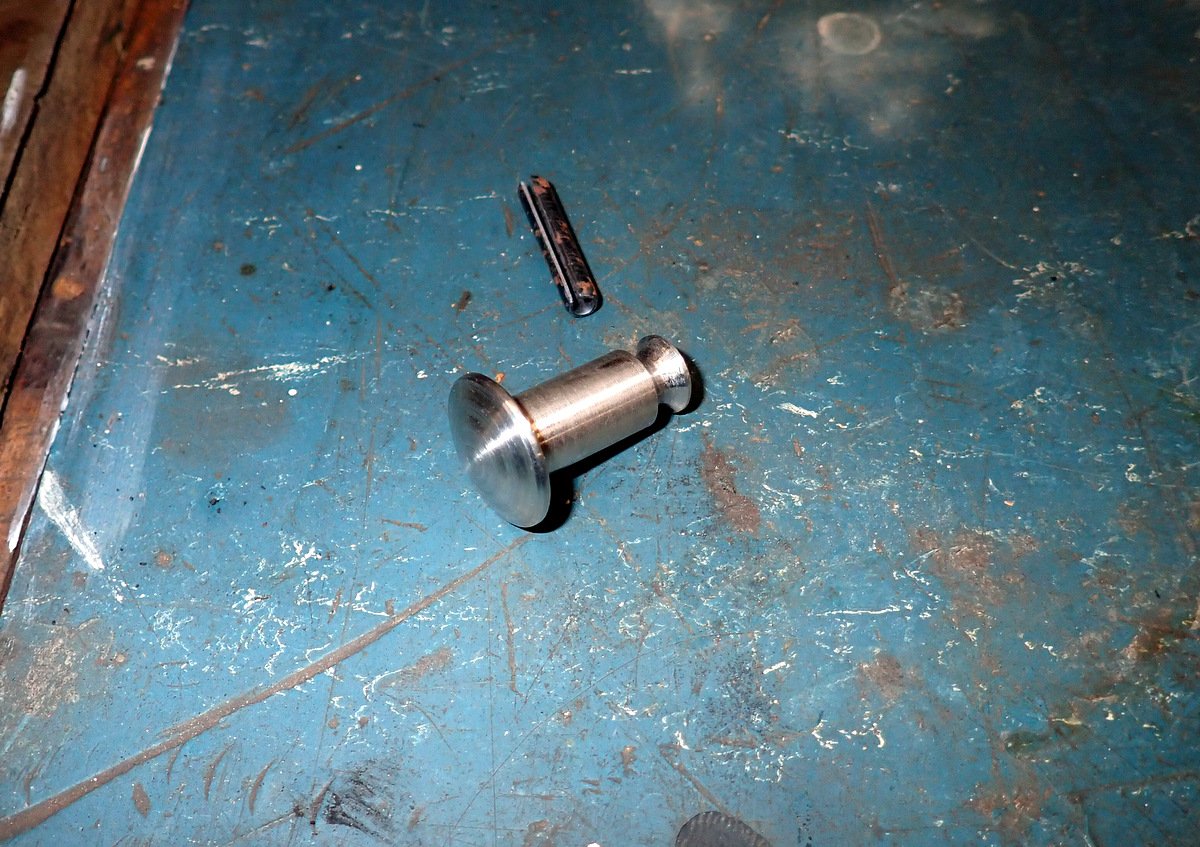
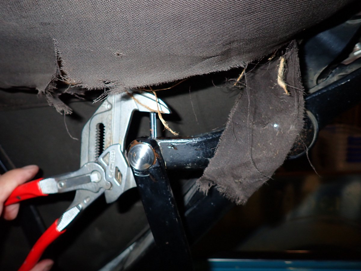
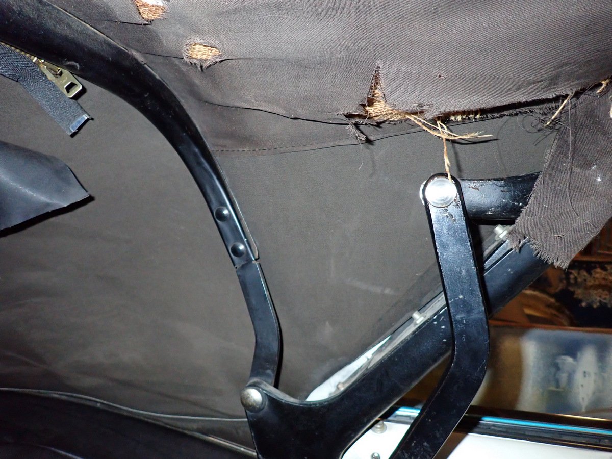
Getting through the list, next up is the missing pivot pin for the convertible top mechanism. The original one broke ages ago but I kept it in place with a set-screw in a tapped and threaded hole in the back until it disappeared in the paint/panel process. Once I finally worked out how it should look I sketched it up. The original one had broken through the groove, it is retained here by a roll pin through the casting. @ajg193 made me a very nice replacement from stainless steel I used the knipex adjustable spanner thing to press the roll ping back in (very handy tools btw) Back together and working without the ugly bolt stuck through there. (see what I mean about needing a new top)
3 points
-
She actually suggested going out in it the other day, she must have forgotten how scary it actually is. I might make an action vid in the weekend so you can appreciate the goodness.2 points
-
2 points
-
Can supply those boxes in disassembled form so crimp your own adventure to suit, with 4 or 5 pin relays2 points
-
Cheers Chris. Interestingly the other chris @chris r recons he's got some for me too I'll be able to fill the whole cabin at this rate. It'll be one super quiet, slightly itchy ride.2 points
-
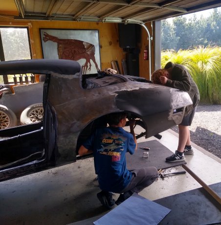
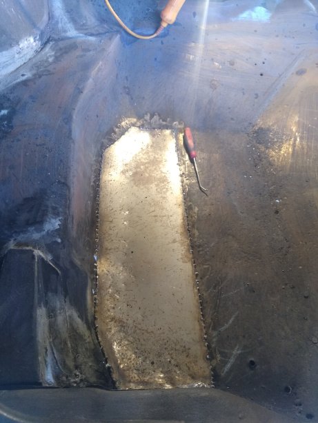
I've been chipping away at this over the last couple of months. The entire exterior is now down to bare metal and I've done about half of the rust repairs. I've been taking it slow as I'm still learning about how to repair cars and do body work. I'm not used to working with such thin steel and the world of panelbeating is much more complex than I'd guessed. I'm really enjoying learning this part of it though, making strange shapes and learning to stretch/shrink metal is a lot of fun. During the school holidays my routine was to make up a little patch panel in the morning, and then weld it in after work. It's an honest life. There were a few holes in the rocker covers, the wheel wells, and the boot that I've already sorted out. While cleaning up the boot I found yet another hideous fix-up from a previous owner, or repair shop. The metal on the inside of the boot, near the passenger side boot hinge had rusted away entirely. Their "fix" was to recreate this structure using aluminium tape and then paint over it in that thick textured paint that you see in wheel wells. Bastards! I've kept a decent run of this tape, with paint still attached, as a memento to go along with the sandwich-sized hunk of filler from another part of the boot. Anyway, progress is being made and luckily all the rust is mostly in the boot and not on frame rails or the underside of the body. So I'm not too put off by it all. Here's some pics of my helpers, son & his friend, who I coerced into making paper templates for the rust holes and some pics of the largest panels I had to make
2 points
-
Definitely experiencing a combination of wins and losses with things right now. I fixed the wiring on my cam angle sensors, and then it actually looked fairly easy to change the wiring to an 8v supply so I did that too. ...Then the motor wouldnt start at all. It looks like it would work well with an 8v supply, if you use pulldown resistors instead of pull up. So pulled the loom back out, changed it back to 5V supply. Once I got this fixed, the motor would fire up again. Sort of. I guess "fire up" is probably an accurate description: What the hell is going on? How can the timing be obviously so bad, but the motor still runs at all haha. Well it looks like the polarity of the crank angle sensor is back to front. So every now and then it thinks its doing a zillion RPM and then ignites on the intake stroke. So some fairly rookie mistakes going on. But I'm slowly sorting through them. I think it should be idling and running properly pretty soon, hopefully. I've not had any time to fit the exhausts on properly so my 1 stroke external combustion engine / fireworks machine is still pretty bloody noisy.2 points
-
I've designed and had made exactly this from carbon, it can be done and CF is no dearer than the other options, its the tooling, time and consumables that add up... Fiberglass would probably be fine, its the resin system that generally defines service temps, no real structural reason to use carbon over glass either. I love sheetmetal, cheap easy and fast, thats where i'd be leaning as a first off, a diffuser cone to go from the 3d print to feed duct desn't look too hard? Not too hard to CAD, print A3 and then cut out.2 points
-
*girly screams of excitement * just got these through
2 points
-
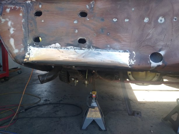
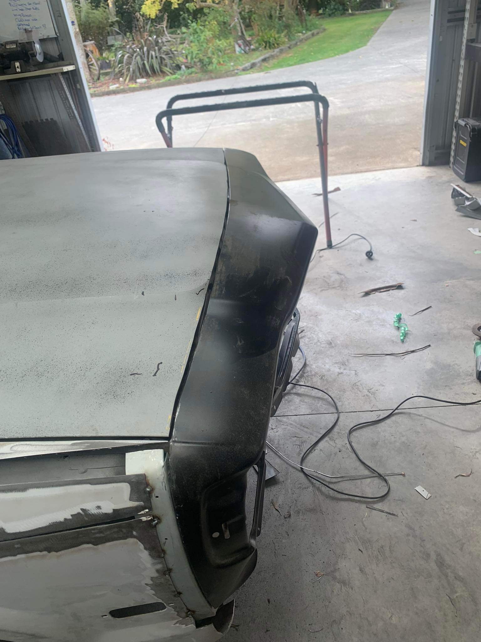
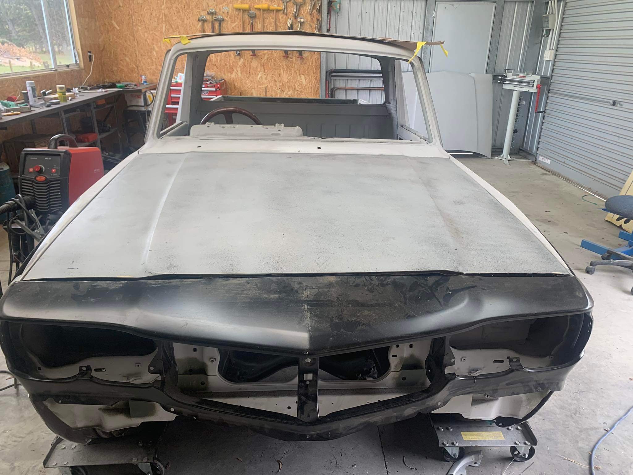
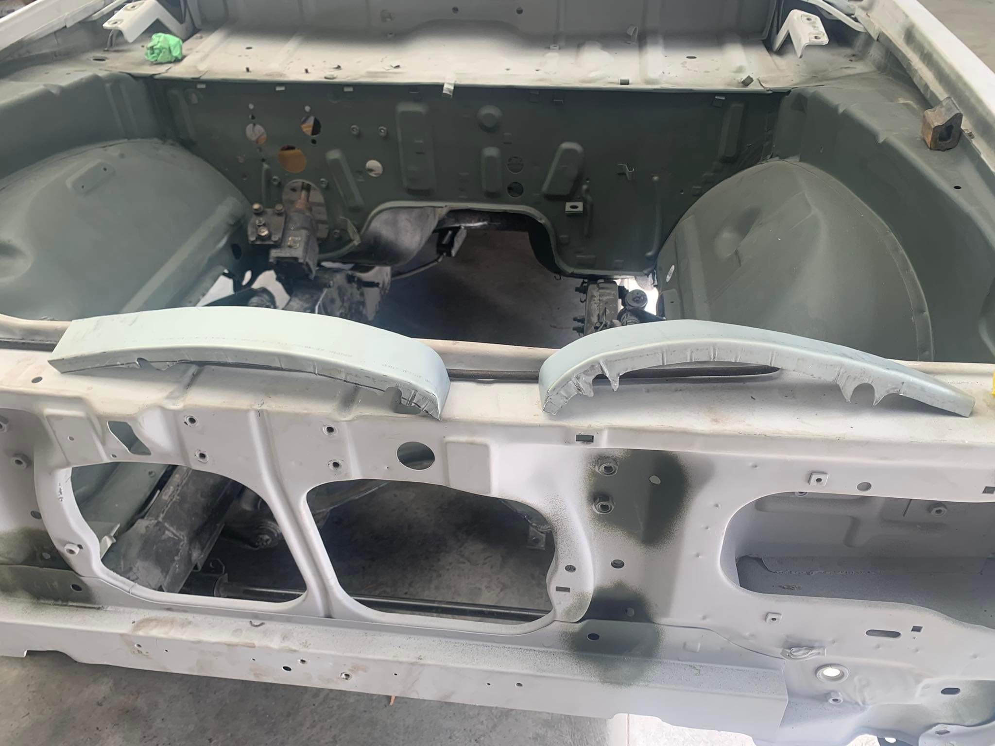
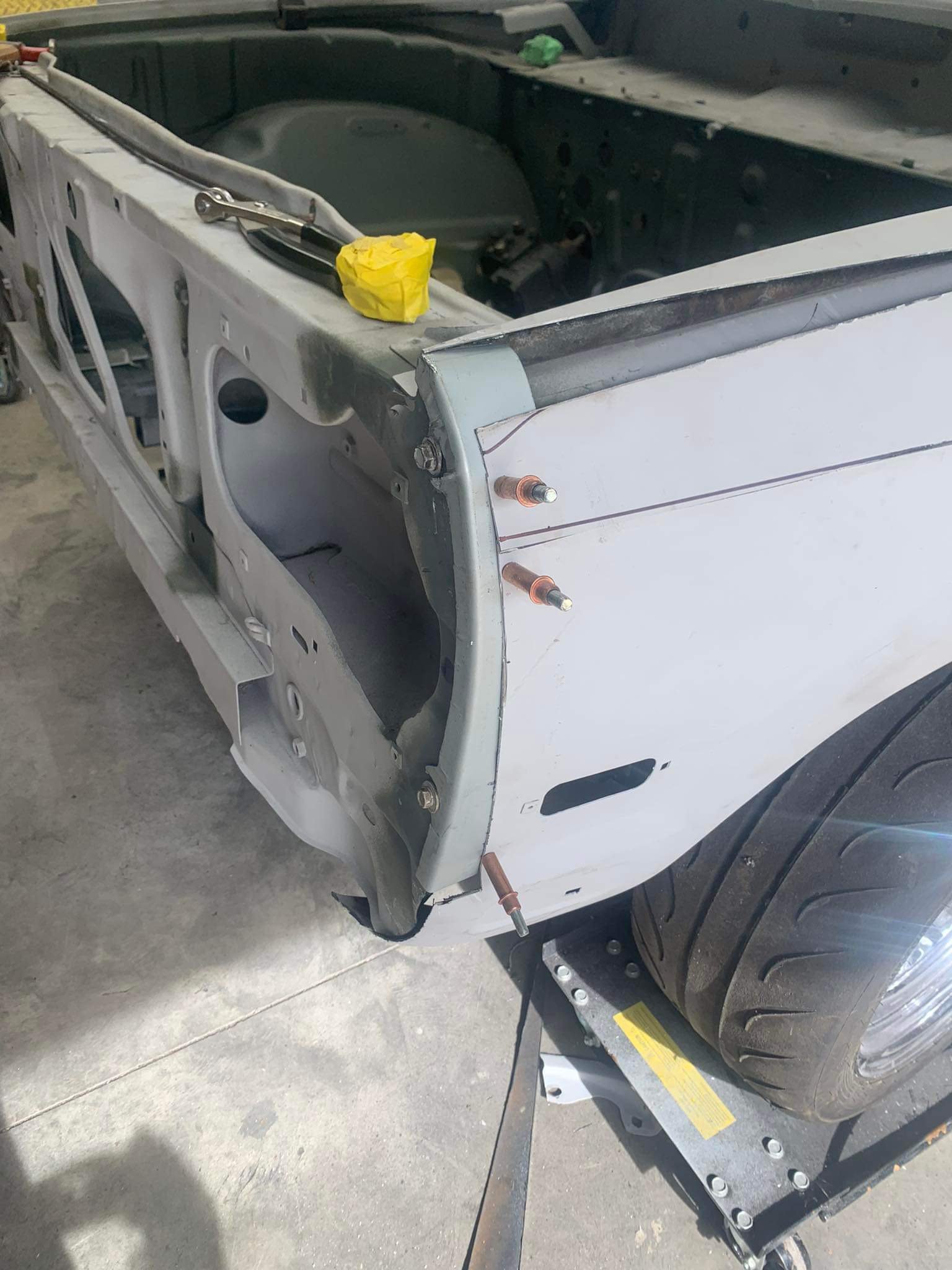
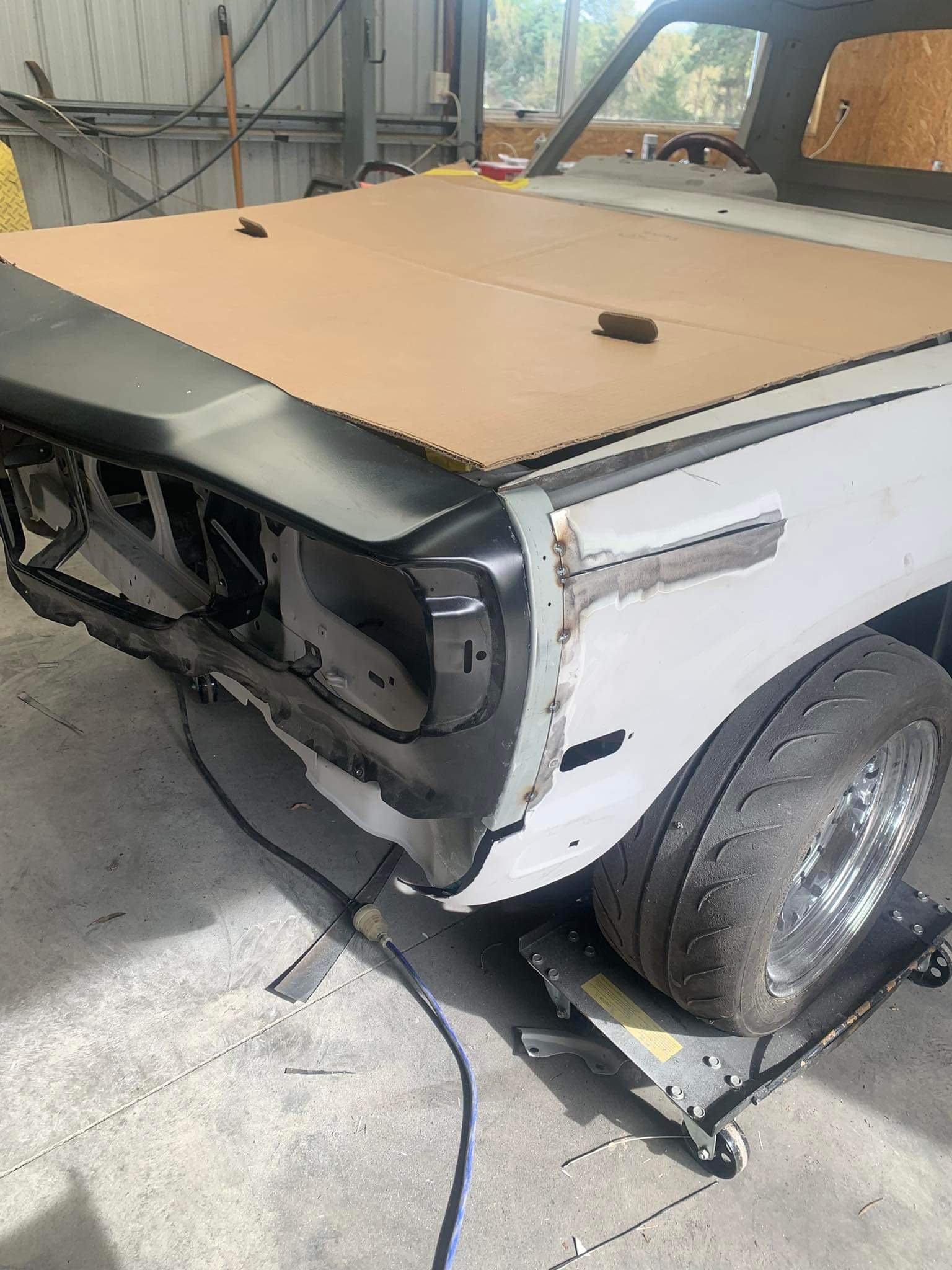
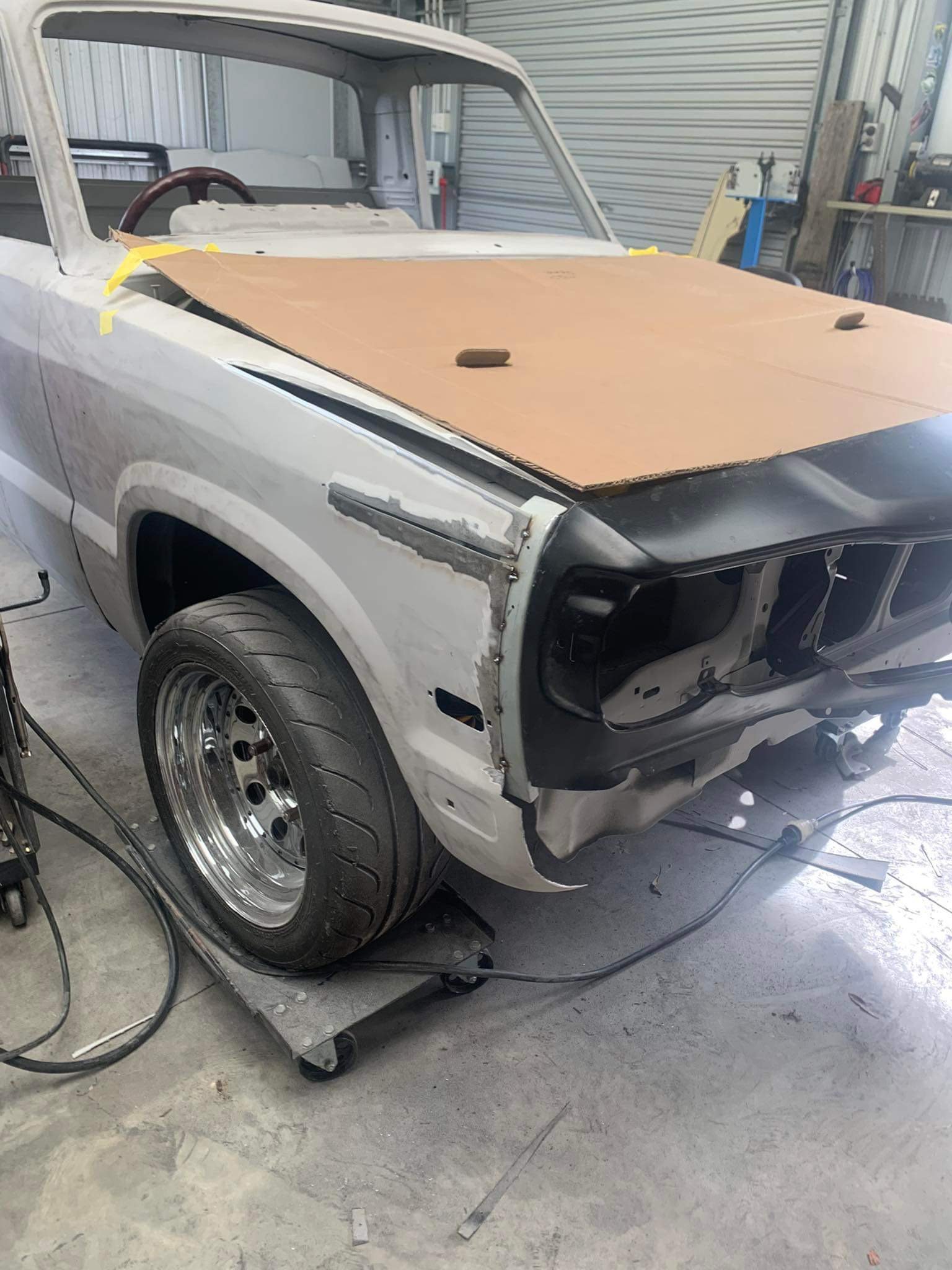
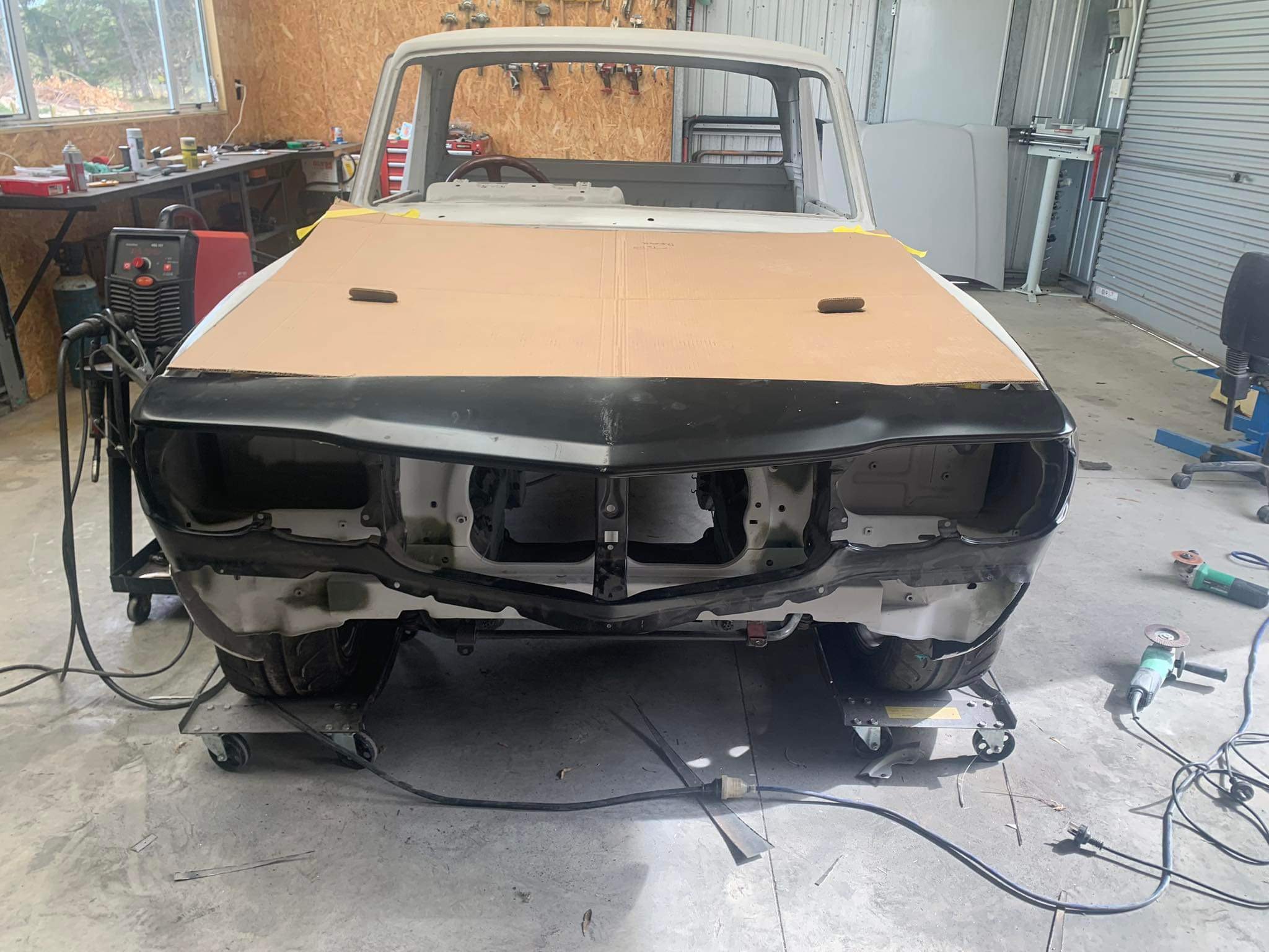
So the above teaser was me dropping the ute off to a panelbeater near palmy. this is his update pics. i just didn’t have the time or mental energy to grind my way through the stitching phase, or attacking the mint bonnet with a grinder. he has made up new flanges for the front of the guards , he won’t use the rx3 guards on this set up, all new steel. have also tasked him to fill over the fuel filler hole as I can’t utilise that once I drop tank it out the back anyway. So now I’m forced to drop tank it now instead of when I bag it. it means that I can carry on with the tubs when it’s back. I will end up using push button bonnet pins, hopefully they’re ok as a bonnet pin for road use. I’ll also fit a check strap as a secondary safety measure happy days
2 points
-
Other than ignition timing changes. All you need to look at is afr and injector duty cycle, same afr and more injector duty = more power. isn't many cases when this isn't true.1 point
-
Bring the HQ!1 point
-
@Nominal probably already found them but for future reference assume these are them (sans picture) https://webstore.autobend.co.nz/product/fiat-124-125-132-short-hooks-10028.htmx1 point
-
Nice link, gives me an idea to ditch all 10!! of the glass fuses in the falcon.1 point
-
Pretty sure we'll be flying and driving a Wounders Inctm vehicle from Cheech to Hanmer. You're welcome to join, @azzurro, as long as you're willing to put up with us for a few days.1 point
-
BUMP. Not worth starting a new thread but I have to re-wire a couple of cars. Namely a series landy and a 67 econoline. I'm not a fan of those wiring kits although I did enjoy using the American Auto Wire model specific one for my Chev. It was rather pricey however. Does anybody know where I can get bulk wiring for cheap? I like the look and feel of the SXL wiring and the last one I got was from Amazon here. Does anybody know where I can get it in bulk for cheap? Temu? Ali Baba? Jaycar? I use this as my fuse/relay block seeing as I'm lucky to even have a heater fan let alone a stereo. I don't need much.1 point
-
best DIY option is probablly an arduino something like this sort of setup https://thecavepearlproject.org/how-to-build-an-arduino-data-logger/, could setup code to run engine protection output with a kill relay or intercept the IAT signal and setup the delco iat table to pull timing etc at a set value, IIRC fault value open circuit they default the -40deg row with a bit of messing around would be able to piggyback off data like tps maf and rpm to have the whole lot logged in one package. most of the commercially available loggers are getting up into aftermarket ecu territory any way, so would be money better spent on an ecu upgrade with the added benefit of onboard logging1 point
-
Thanks Bart, you are right we DO deserve it. Unfortunately its a punishing drive (2 days each way) and my good lady vowed to never do it again after Nats, at least not in the the 2300 (which had a strong fuel smell inside and a loud exhaust, at least then)!1 point
-
No can do Harry, plates pretty full. Ken one year though.1 point
-
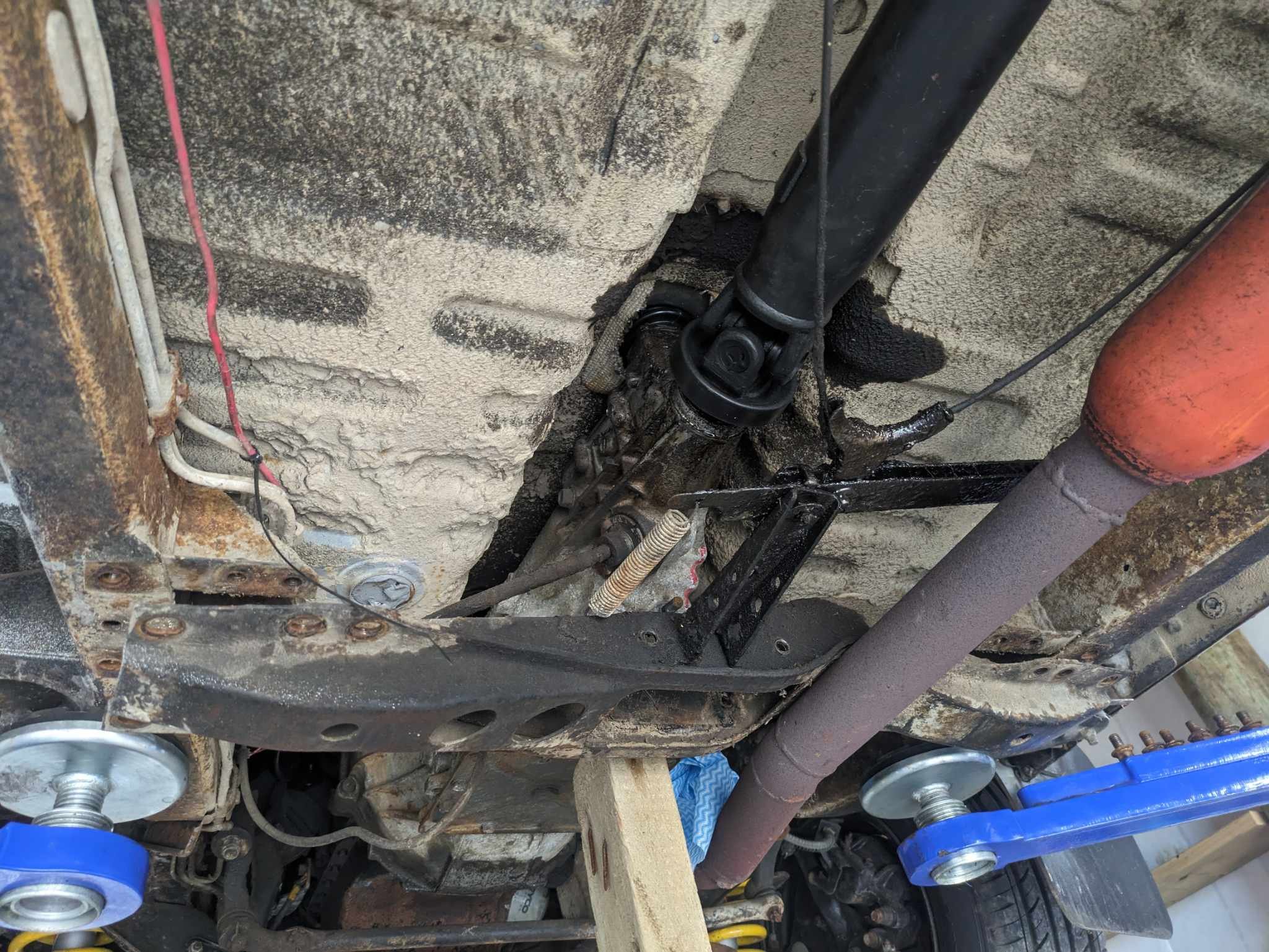
One of those days sadly with some wins and losses. The starter died so I managed to score a complete 4g63 and take it off that. Starter works so mission accomplished there. However there has been a vibration between 90-100kph that is getting on my tits. So with the uni's all being new and feel solid with no movement, I figured the next culprit could possibly be the sagging gb mount which may be throwing the tailshaft out of alignment. I found what I thought was the right one for the right year and although I had to undo quite a few bolts to get the cross member out, the mount doesn't line up. So I either have to put the flogged out one back in or modify the new one. Good times.
1 point
-
Youre going to have to speak a bit slower for those of us who arent electrical engineers.1 point
-
Another house viewing so back at the beach
1 point
-
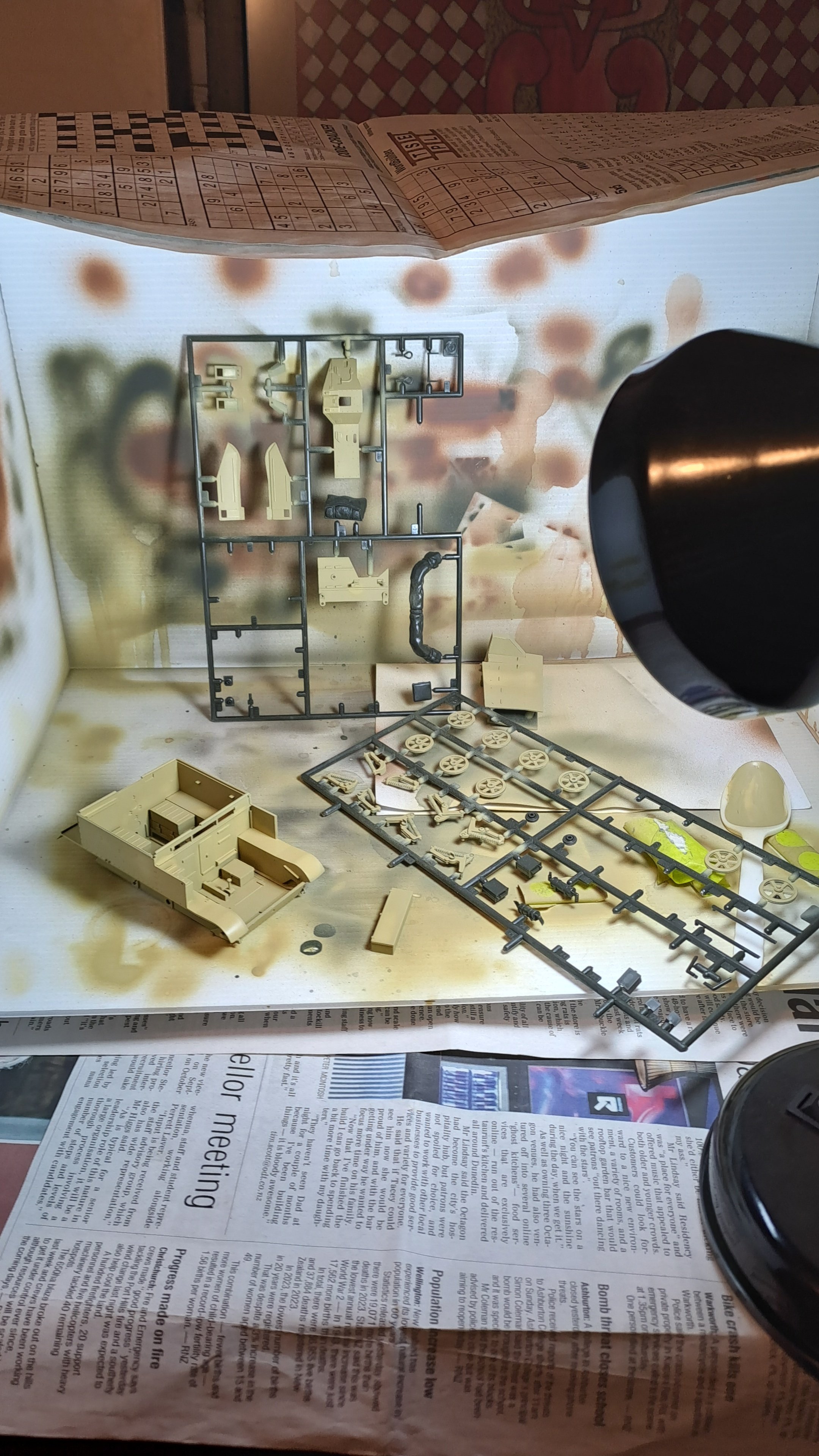
I needed to fix some overspray on the Stug, but didn't get around to it. That said, I'm about 80% done with the wheels, so touch wood, we should come together for the final bits. Then I'll try my hand at some weathering. Keen to pull finger and get it over the line, has taken too long. Also have my eyes on other kits, but will try to restrain myself until I get the Stug done at least.1 point
-
Not much to report, going for a warrant tomorrow. Ive always had an issue in the indicator switch..can never have a flasher and a brake lamp at the same time unless you jiggle the stalk. I tried a few things to fix but ultimately got nowhere. Rock auto to the rescue again, landed this whole unit for about $80nz The fuckery comes from these 4 contacts and the back of the cancelling cam (rewind a few years to when i replaced the broken one with a rockauto seperate 2 wire unit. Theres enough slack in it that the gravity acting on the stalk at rest pulled it onto or off neutral contacts. Well this new one was proper Chinese. I spent another hour seeing if i could fix original or use chang one for parts (the alloy stalk pickup was staked into the plastic cancelling cam and original was slid in so i couldnt really cannabalise it without risk of the slop coming back) but in the end it made more sense to run it, so i had to: -file the slot the stalk locates into from a V to a U while avoiding putting too much pressure on the whole plastic part. - cut both hazard knobs in half and join with some steel rod as a spine because it worked opposite to OEM and bottomed out on the column shroud, and looked shit - slice/shave the OEM plug to accept the chang copy. Was kinda glad i went to the effort of pulling the column apart & half way out to pull and push the loom plug through as i found a bare wire. I'm hopeful this was the reason i saw a wee wisp of smoke exit the shifter area one day sitting at the lights with foot on the brakes. So its all back together and works as it should! Haven't been able to daily it as much as id hoped cause the boss is being a weird cunt about parking in driveway or out front like i always have and relied on. It doesn't fit in the street parks. Have rocked it any other chance i get though!1 point
-
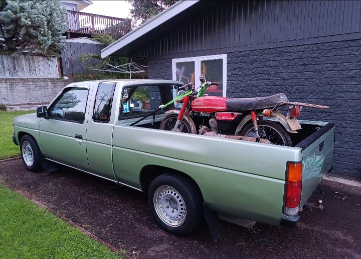
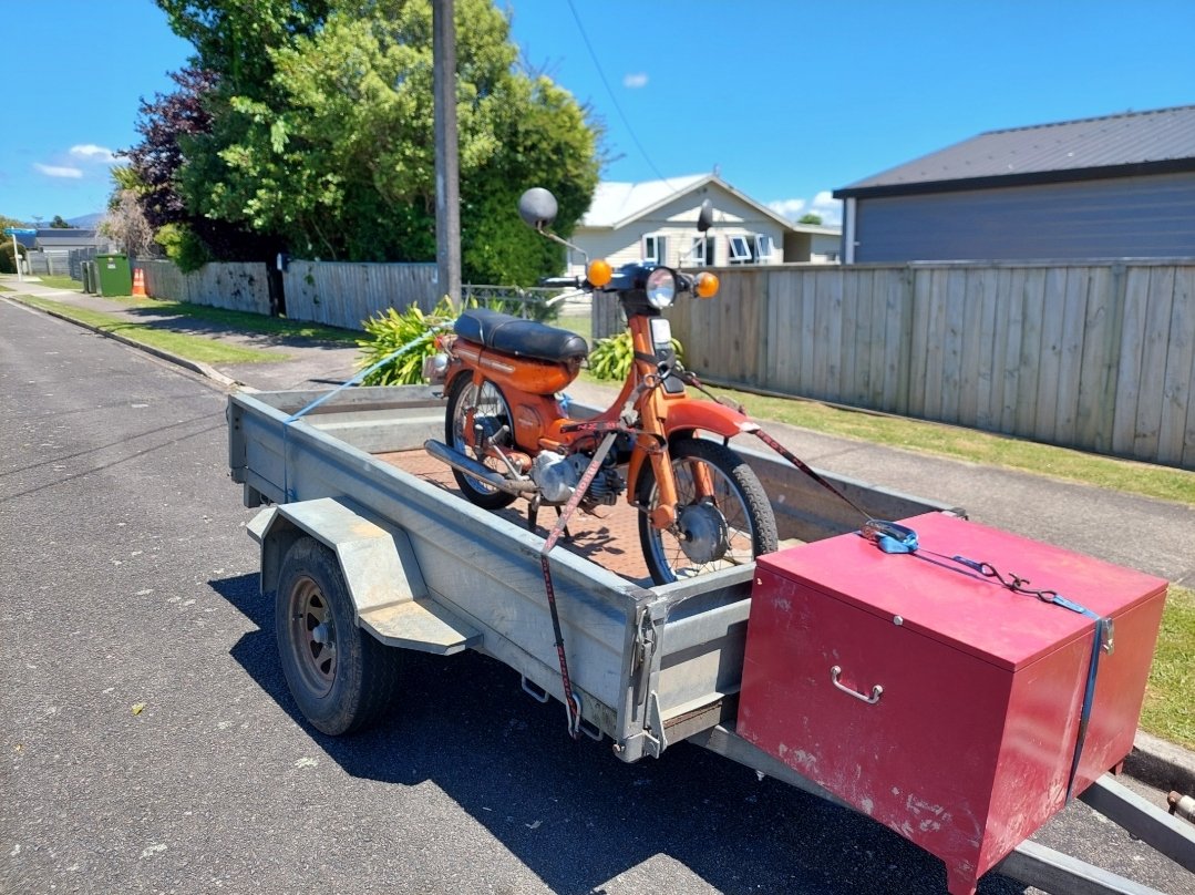
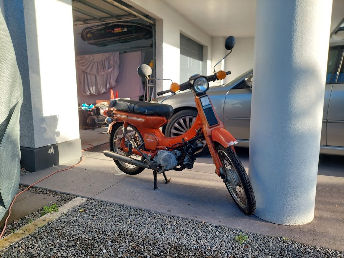
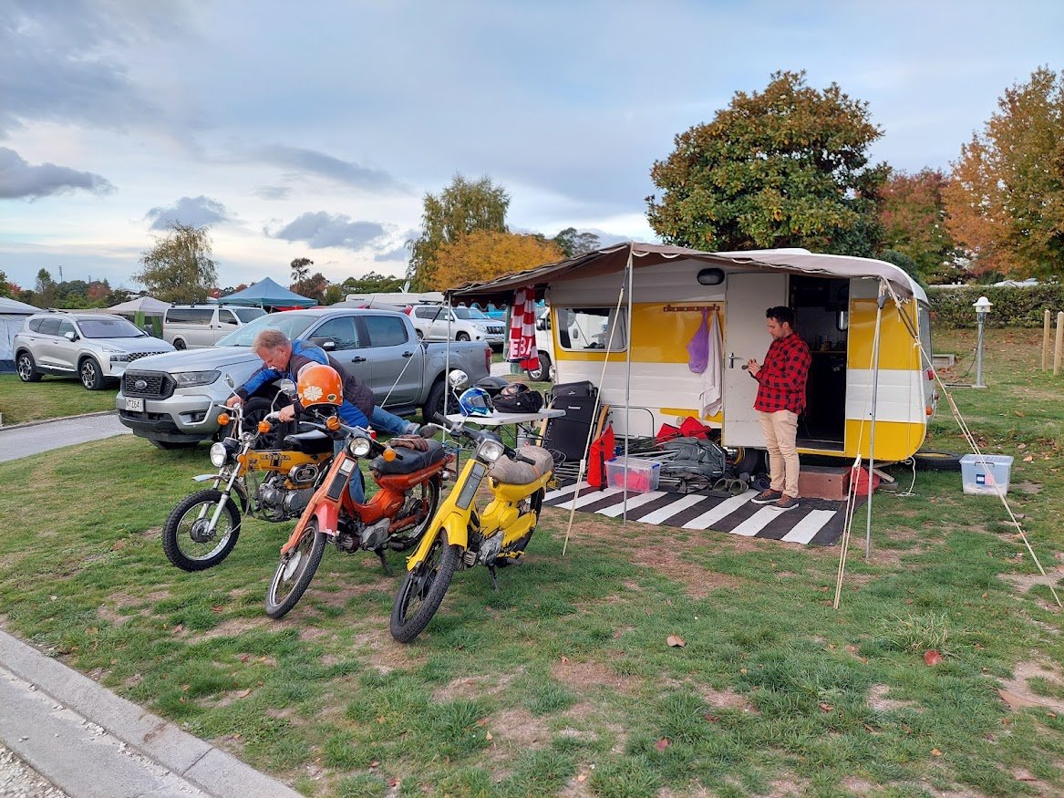
Late last year one saturday night I got sent a very interesting marketplace link by bad influence @anglia4, for a 74 Yamaha V50 that was 20 minutes down the road in Inglewood. No price, make me an offer. I messaged old mate immediately with what I thought was a decent price, he came back with a counter and "please come and take it away so everyone stops messaging me". Turned up the next morning and it was mine! He said that he'd had over 300 messages by the time I arrived to collect it . The Mrs happened to be away for a girls weekend while this all went down and the timing worked so well that I picked her up from the airport with the trailer and scooter still hooked up. It had lived many years as a dairy farm workers commuter which then got abandoned on the farm to pay off a debt or something. It sat there for a year or two until the owner decided to get rid of it. He'd kept it running so when I arrived to check it out and pick it up it started first kick. Fuck yeah. It was pretty grot from sitting on a farm, cow shit and mud caked on the underside, bunch of surface rust, old cracked tyres, switch blocks busted, a couple of blown bulbs and and no rear indicator lenses. Battery is poked but like all good old bikes it runs fine without it. Ignition barrel is hotdog down a hallway loose so the key on a bungy clip so when it falls out every time I go over a bump I don't lose it. Cleaned all the crap off, threw some new Vee (for Victory!) rubber on it, new sparkplug, and a couple of new bulbs and started riding to work errday. Man it is fun. Max pest potential. GHFWII. Fastforward 6 months and @anglia4 and I decided to take our mopeds to the V8 supercars for some pest action. I thought I should probably get it registered before this. Popped down to VTNZ, filled out the form, bit of chitchat with the office ladies and a shiny new moped plate was mine. Too easy. Great weekend at the V8s was had, we did some pesting around Taupo and had them parked in front of the campsite which got lots of great comments. No major plans for future upgrades. A PW80 or V90 engine would be rad but I'm pretty happy with it as is.
1 point
-
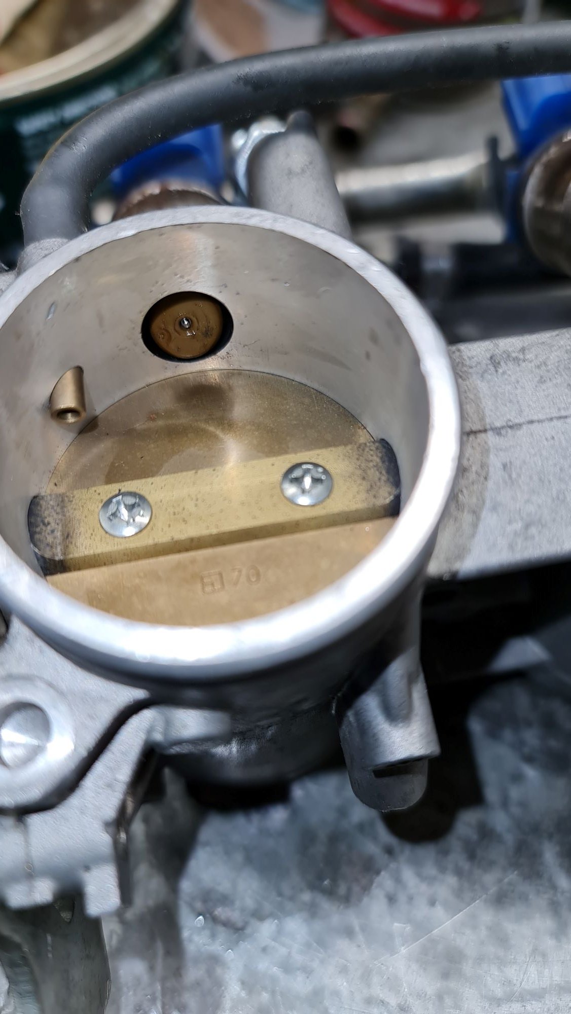
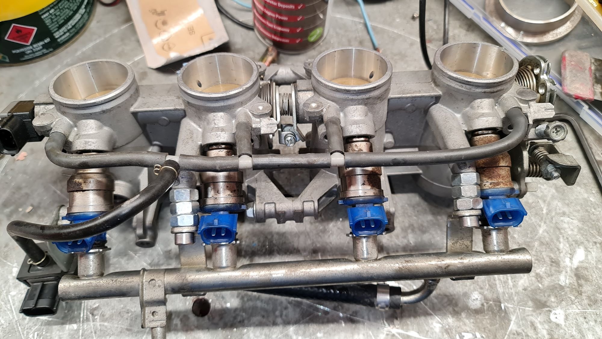
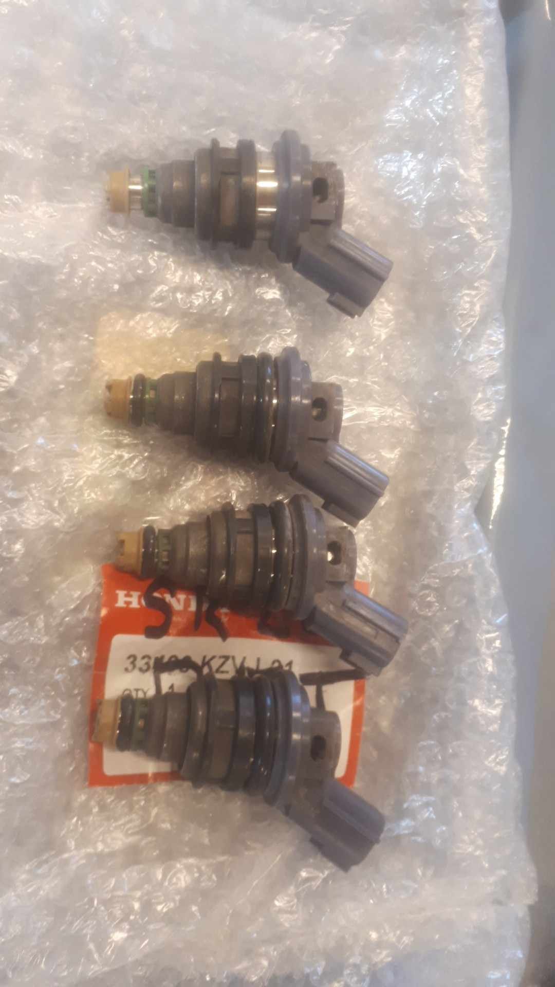
The bike ITB's didn't come with the injectors and they needed to be a long pintle type. I was originally going to try use some 1jzgte vvti injectors I had already and see if the short pintle was a problem. But then I looked at the b6ze mx5 injectors and they are quite long too. Test fit, using some o-rings that fit the bottom end and spaced out the fuel rail with some nuts. Looks like they are meant to be there?! They are a basic single hole type unlike the 1jz ones but should still work, plus bonus is they sit pretty much flush too:
1 point
-
Some work on the bren gun carrier last night
1 point
-
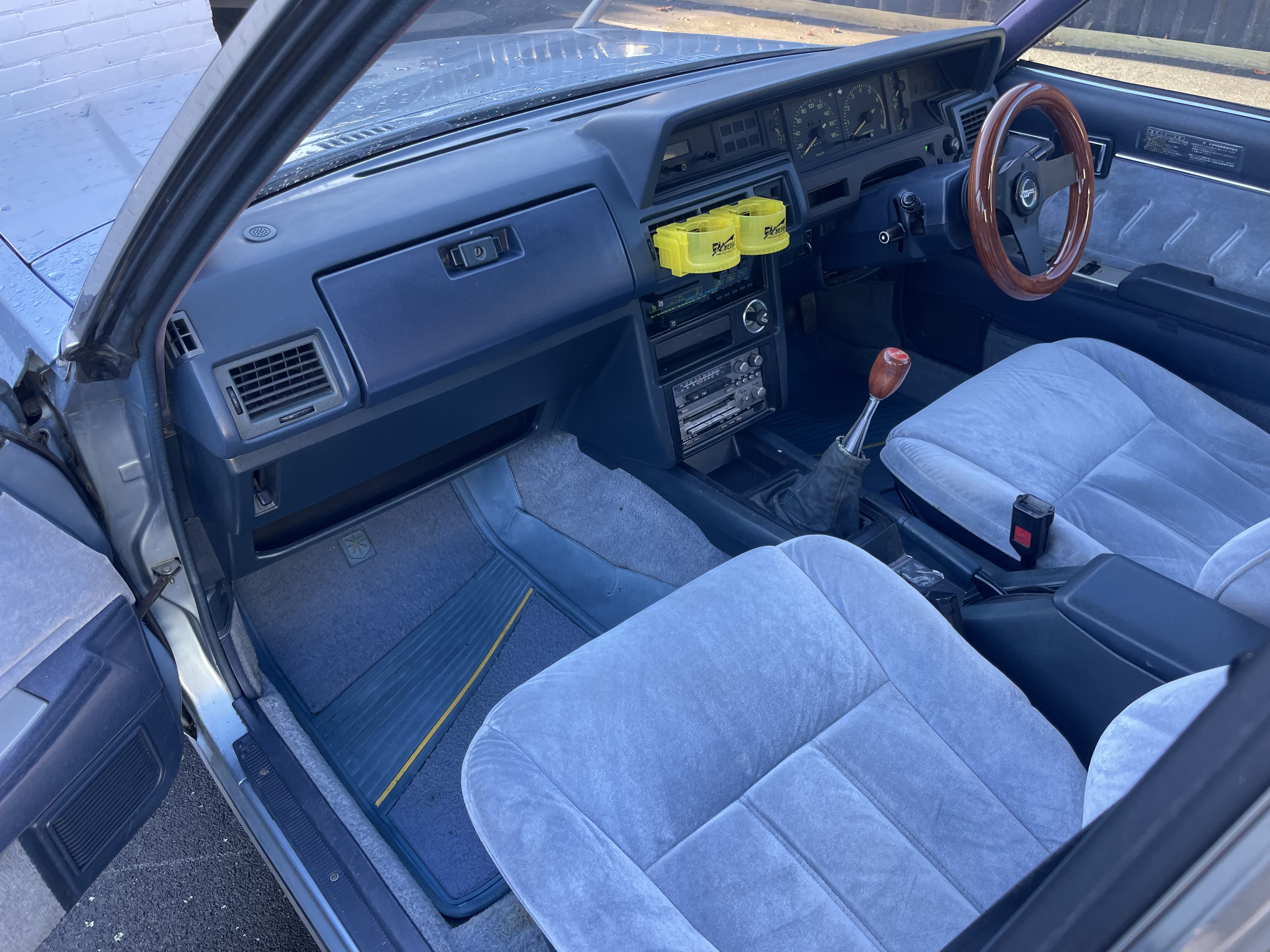
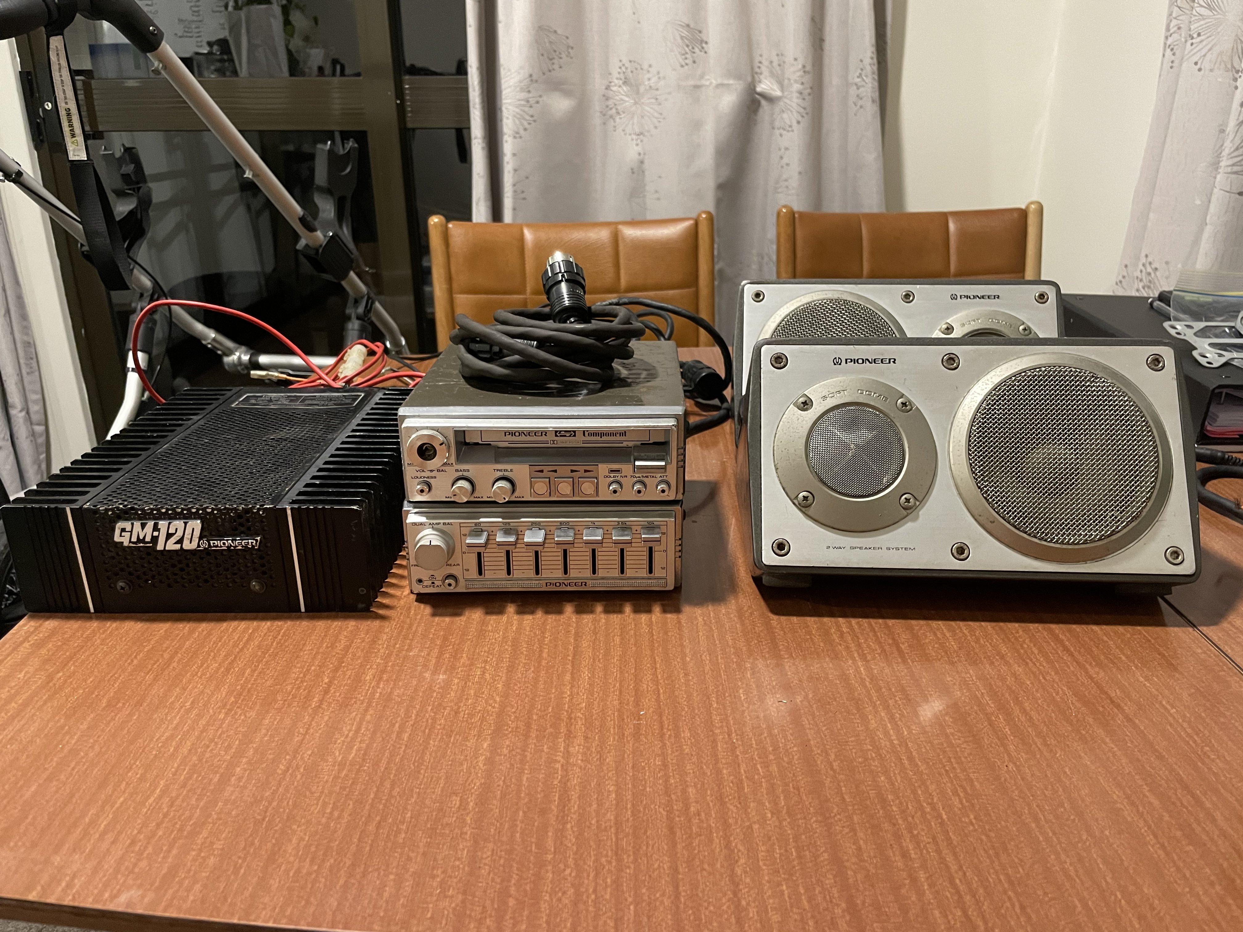
Managed to pick up a pioneer lonesome car-boy component stack which consists of a kp-707g cassette player, cd5 equaliser, gm120 amp, I already have a gm4 amp too, and a pair of ts-x9 to top it off, it also came with a pair of small ts-1655 speakers and a Kex-70 tape player too. spent afew hours cleaning with a tooth brush and metal polish to get rid of some corrosion and got it looking presentable. tried to bench test the setup but it doesn’t seem to be playing ball, I got it all connected up, the tape gear spin if I falsely load it without a tape, but as soon as I load a tape in it doesn’t seem to have enough juice to spin the tape. I don’t know enough about this stuff to pull it to bits. I also need a volume knob as the one on my cassette player has been snapped off so if anyone has a spare sitting around would be much oh appreciated. also pulled the original floor mats out of the boot this weekend and 40 years hasn’t been super nice to the rubber on these and the drive side is starting to crumble apart but they are near impossible to find so will do for now, gave them a scrub up and they came up pretty nice.
1 point
-
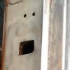
First job ticked off. Welded up a box for the gearbox cover. The only thing it does is provide access to the selector uni grub screw. Even that's pointless if when taking the engine and box out I slide it backwards. If the engineer asks me to weld it in it wont be a big deal. Just a faff around with making sure it doesnt catch fire. I have to put the rear seat back in sans some springs in the middle. No biggy.
1 point
-
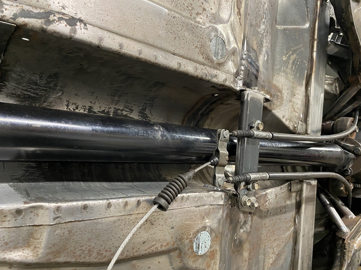
I made the handbrake cable bracket. I can make the cable outer touch the propshaft flange, so I'll make some brackets to hold them away. I'm fairly confident they wouldn't touch by themselves anyway... I must decide how I want to marry the Triumph handbrake lever to the toyota cable so it's still adjustable. The handbrake is offset to the drivers side, so the cable 'just' misses the propshaft.
1 point
-
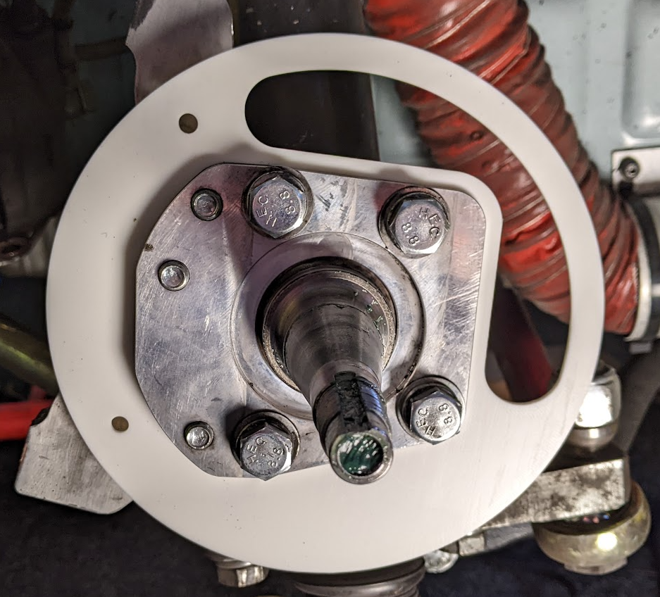
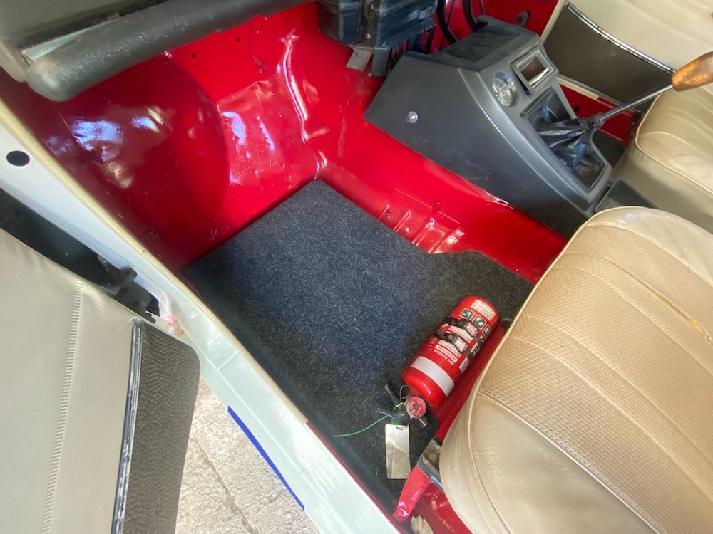
I got it all back together and has all of its gears so I'm calling that a win. It also does not appear to be leaking any transmission fluid, another win. So then I looked to the wheel bearing situation, and smashed that out. There is a dedicated X1/9 forum, Xweb, which has a lot of excellent info and how to's. I found a great pictorial run through of the process and set to. I did need to make a special tool to remove a locking ring but that was no drama. Octagonal lock ring fuckery. Special tool made by a special tool. That and the engine going in meant Sunday was quite a big day, so I left the tie rod end for tonight. On the basis of this minor last task I booked the car in for its recheck and a wheel alignment. After work I went down to sort it, only to find that the rod end is the wrong one, and about 50mm too short, GAHhhh! It took two weeks for the last one to arrive, I am so disappointed. Anyway. Previously to this weekends shenanigans I had done some messing with the jetting, and drilled the mains out to 130 from 125. So I took it out for a short run so I could bleed the cooling system properly and check the AFRs which were much improved, as was the idle to main circuit transition, so that at least was good.1 point
-
could you maybe make 2 halves from some MDF, then use that to press the shape into aluminium and then weld together, if you get some O state alumimium its very workable...1 point
-
Youve got two radiused ends on the plate, I would start with two split tubes at each end of the curved slot then curve some flat to stitch in between then duct from there. 3D printing something would be a good way to get a feel for the shape but analog is sometimes easier to figure out on the fly to start with.1 point
-
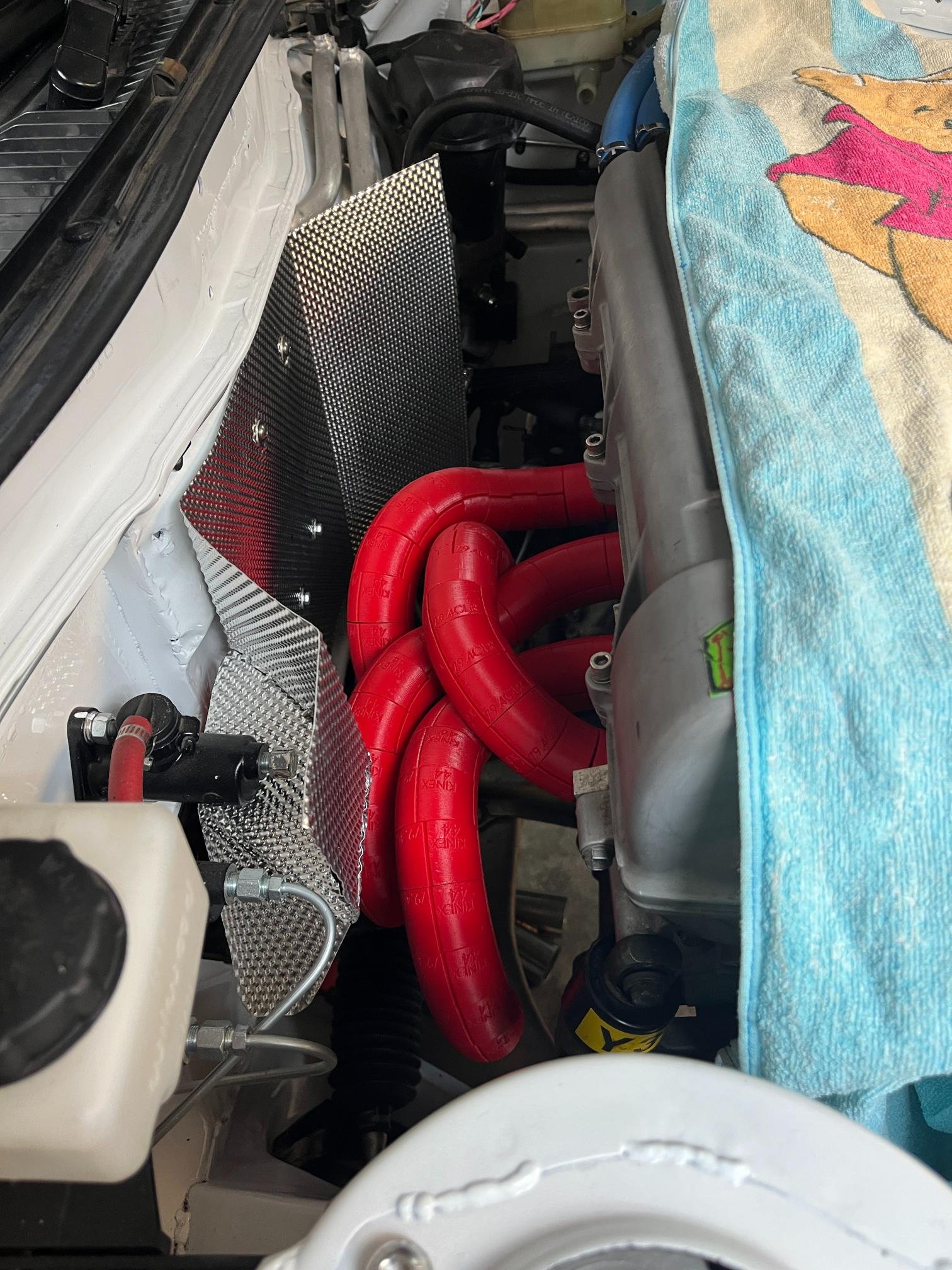
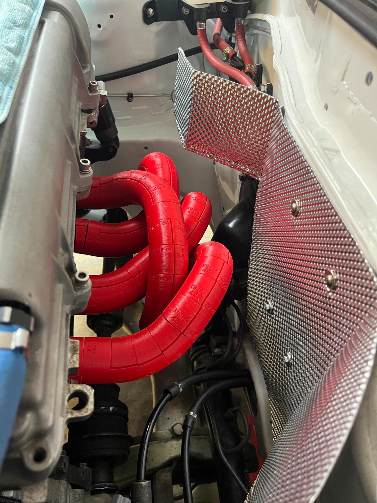
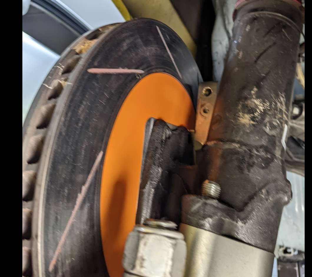
Always open to feedback. Old one seemed to be ok for 5 + years? It's AE86 front struts so hose goes straight to chassis mount, so hose is taking all the flex. There so some pressure on the plate, but there is a tiny bit of flex in it? I am considering bracing the inlet against the strut to take any movement out of it. Yeah the aperture is one concern i have, but i really need the biggest hole i can get. (Guess one option is to get the whole thing made out of carbon) Air is coming in from the strut side from high pressure zone on the front spoiler through the orange pipe. Race car only, rotors are seeing sustained 600c +, this is a 267mm x 25mm disk all under a 13" rim with a 12 lap race where i'm often in traffic, so getting rid of heat is a big problem, so it needs more than your typical race car. Good idea! hadn't considered that approach.
1 point
-
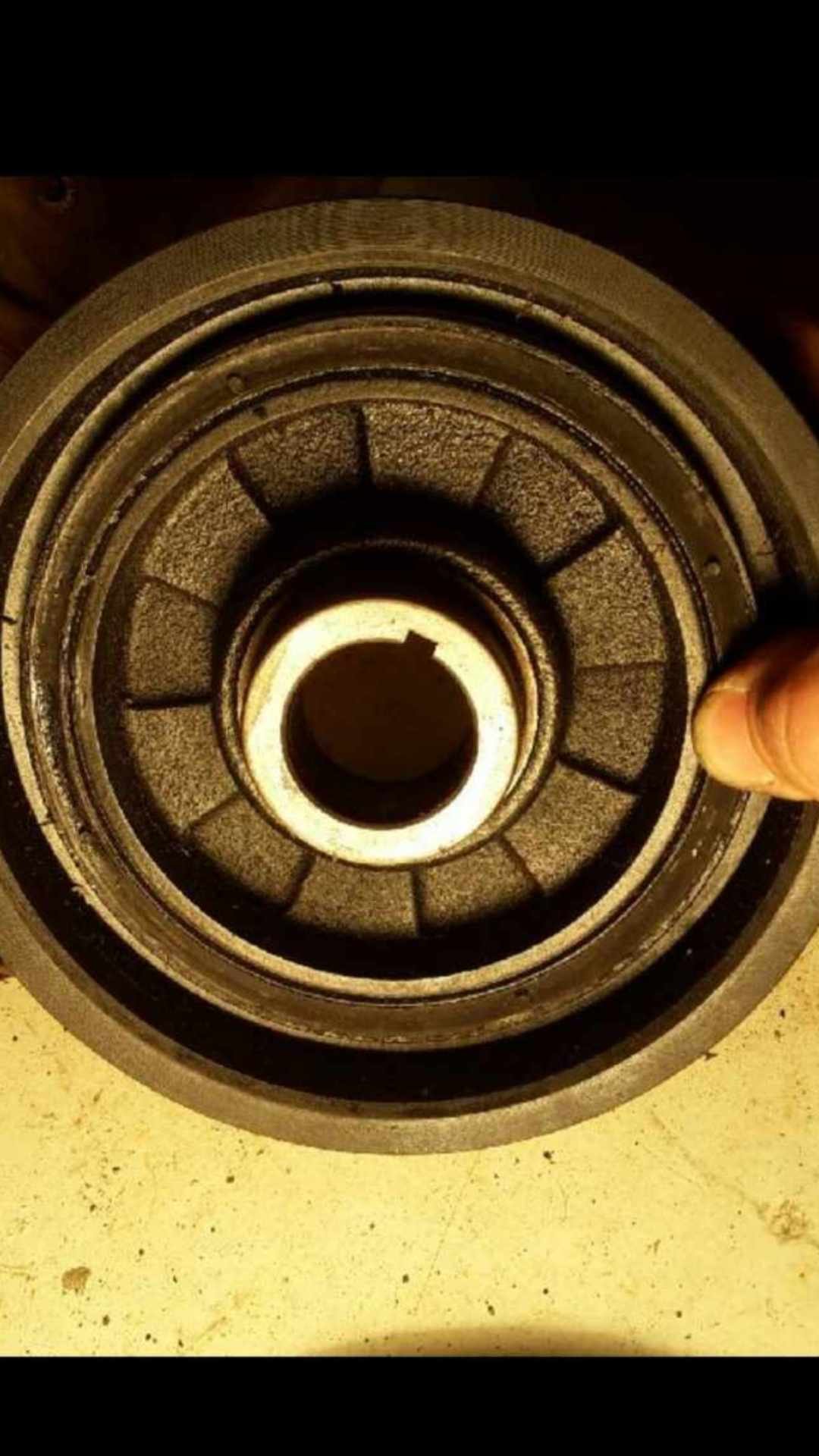
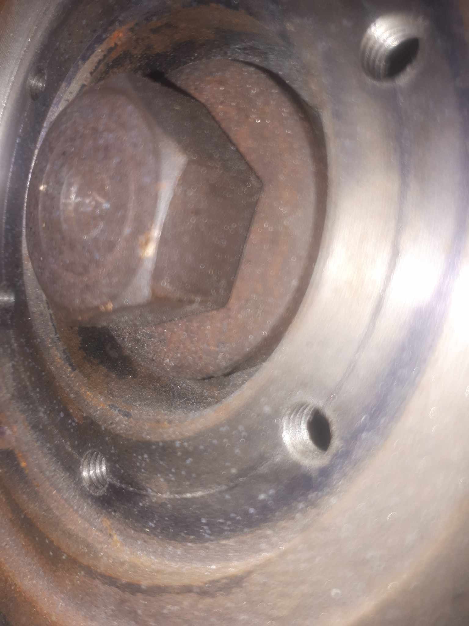
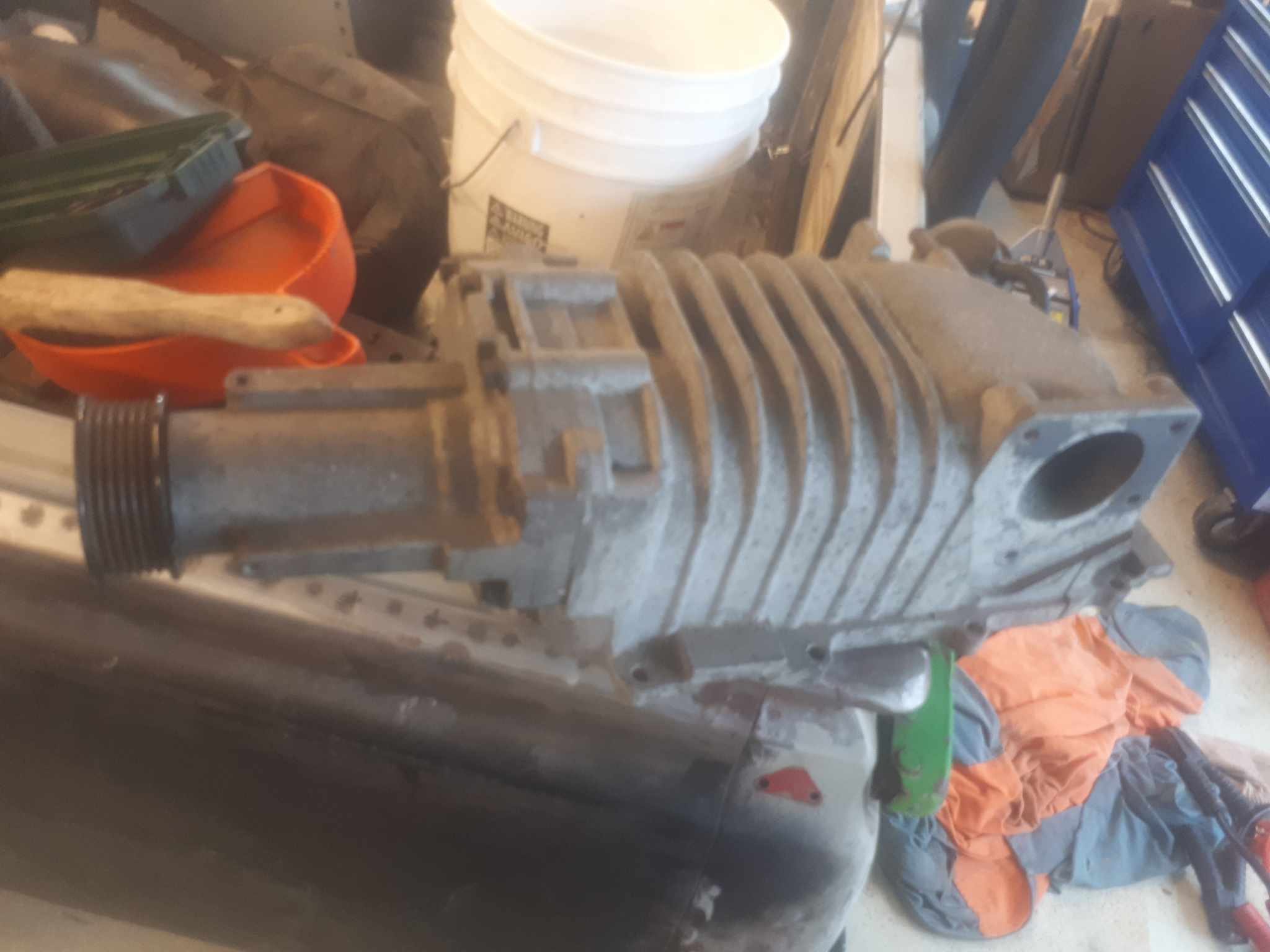
PNot an update as such, more a musing/potential future upgrade. Upon procuring the engine, id noted the front crank seal had been leaking. I whipped the crank pulley off, and much like the pinion seal on the diff, the seal journal was quite rutted/cut into. A speedy sleeve put this back to new. While i had the crank pulley off, i noticed an interesting shape was present. So i figured while it was off, it would be a travesty not to machine off the power steering pump pulley, (these are attached to the main hub, not the dampered pulleys that drive the water pump/alternator/AC) A nice spigot was machined on, and some holes drilled and tapped to correspond with those nice bosses. This is very hard to photograph in the car. Quite a while ago, the old boy picked up an Eaton M62 supercharger off Ebay. It came off a USDM nissan frontier truck, with the nissan VG33ER. (The larger version of the single can VG30 which were once common here) i basically told him, i was commandeering it. And back when @Vintage Grumblewas a cool kid, he had some SR20det injectors which he kindly gifted to me. So in the unlikely event 5his wreck ever sees the road, it wont be too big of a stretch to turn the wick up.
1 point
-
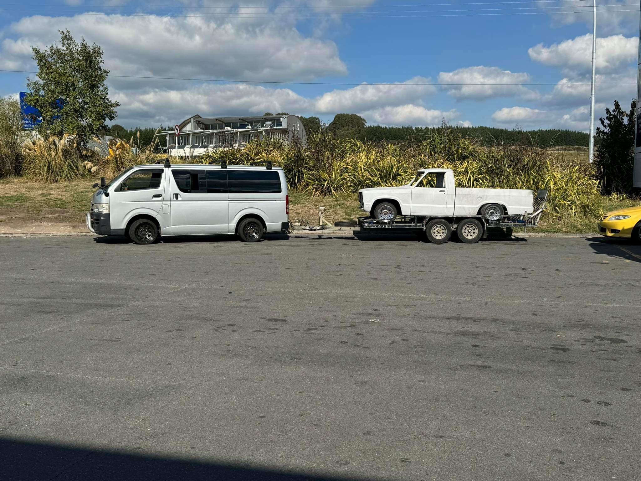
And just like that she’s gone….. dropped off to fielding what a Kent of a drive. Started with a flat tyre on the van, so had to swap all 4 wheels over from the other ute, that was a mission in itself. then drove all the way to fielding, dropped it off and refueled. As soon as I hit the main road from palmy to Sanson the ECL and DPF lights came on. limp mode engaged, no boost. FUGH!!! decided to send it. Hills were fun. crawled into the drive at 2am the next day after starting at 10am. van is booked in for a service and dpf delete next week
1 point
-
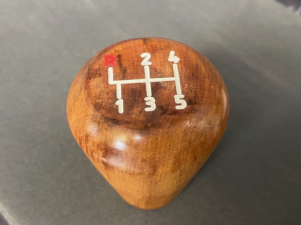
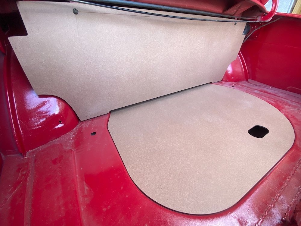
After guessing the shape, dad provided me with dimensions and photos of original boot panels, gave the CAD model an update, grabbed a sheet of 4.75mm hardboard and set about probably the most to factory spec part of the rebuild! Also carved up a gear knob from scrap rimu with the correct shift pattern, scrubbed up real nice with linseed oil too.
1 point
-
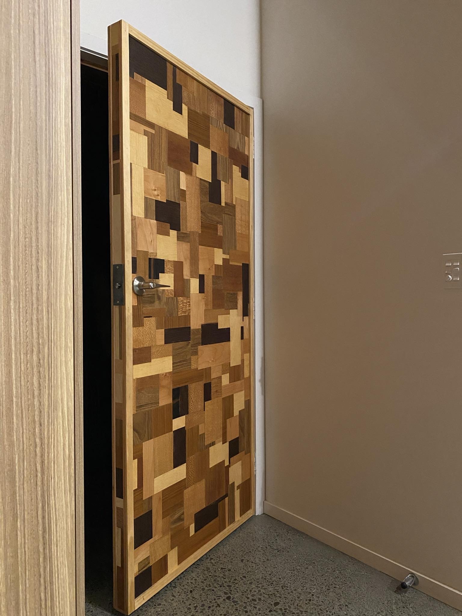
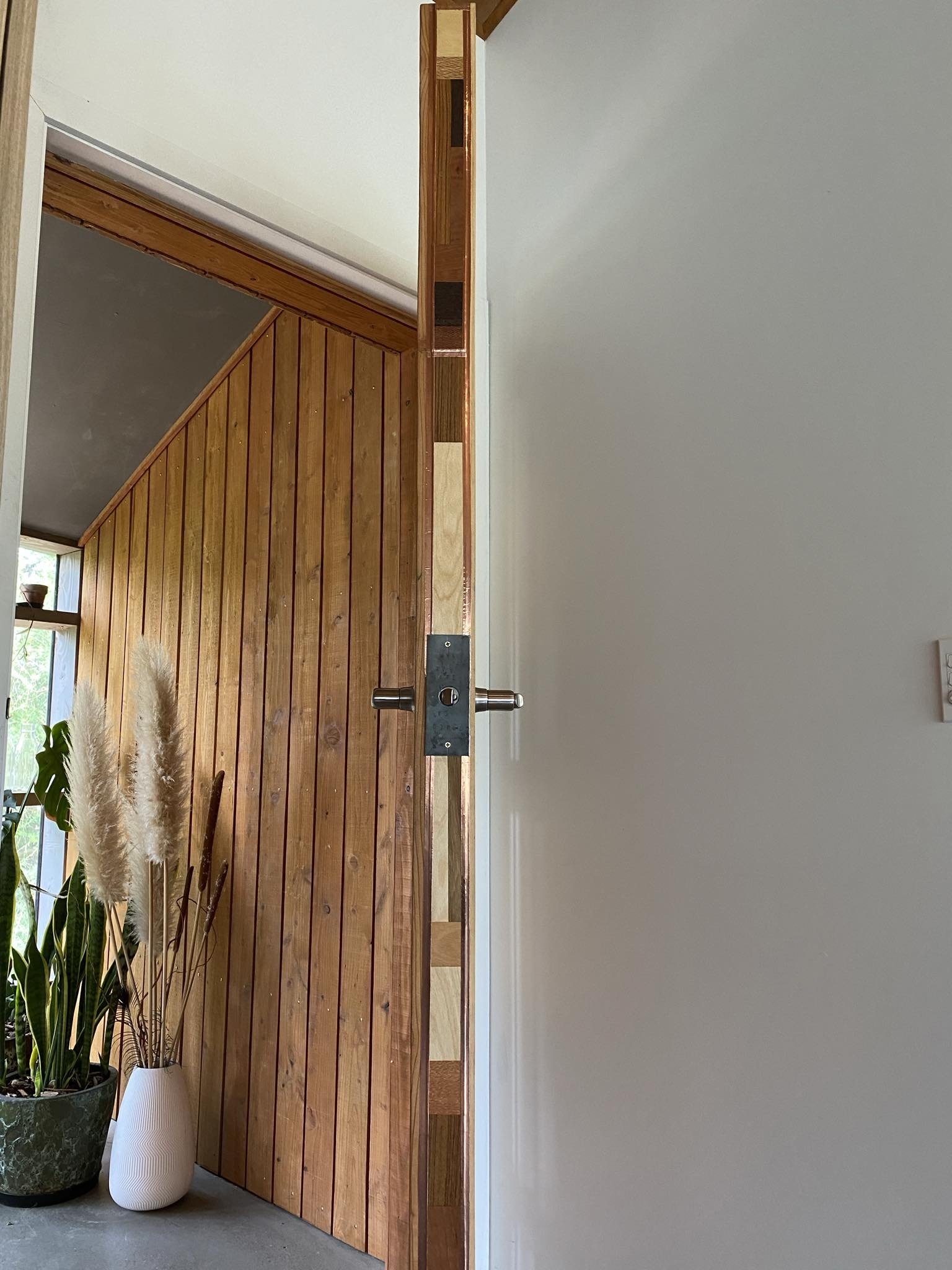
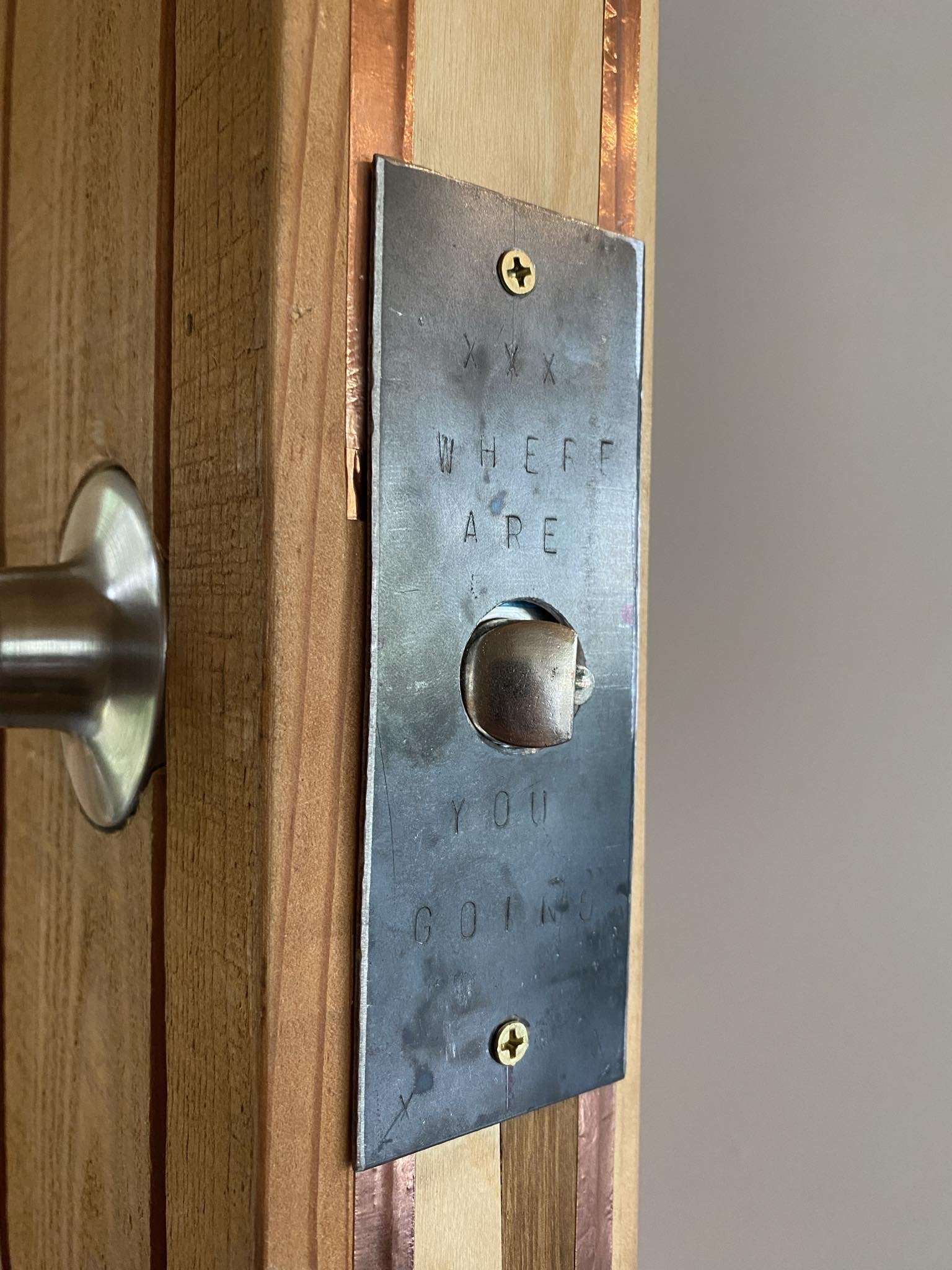
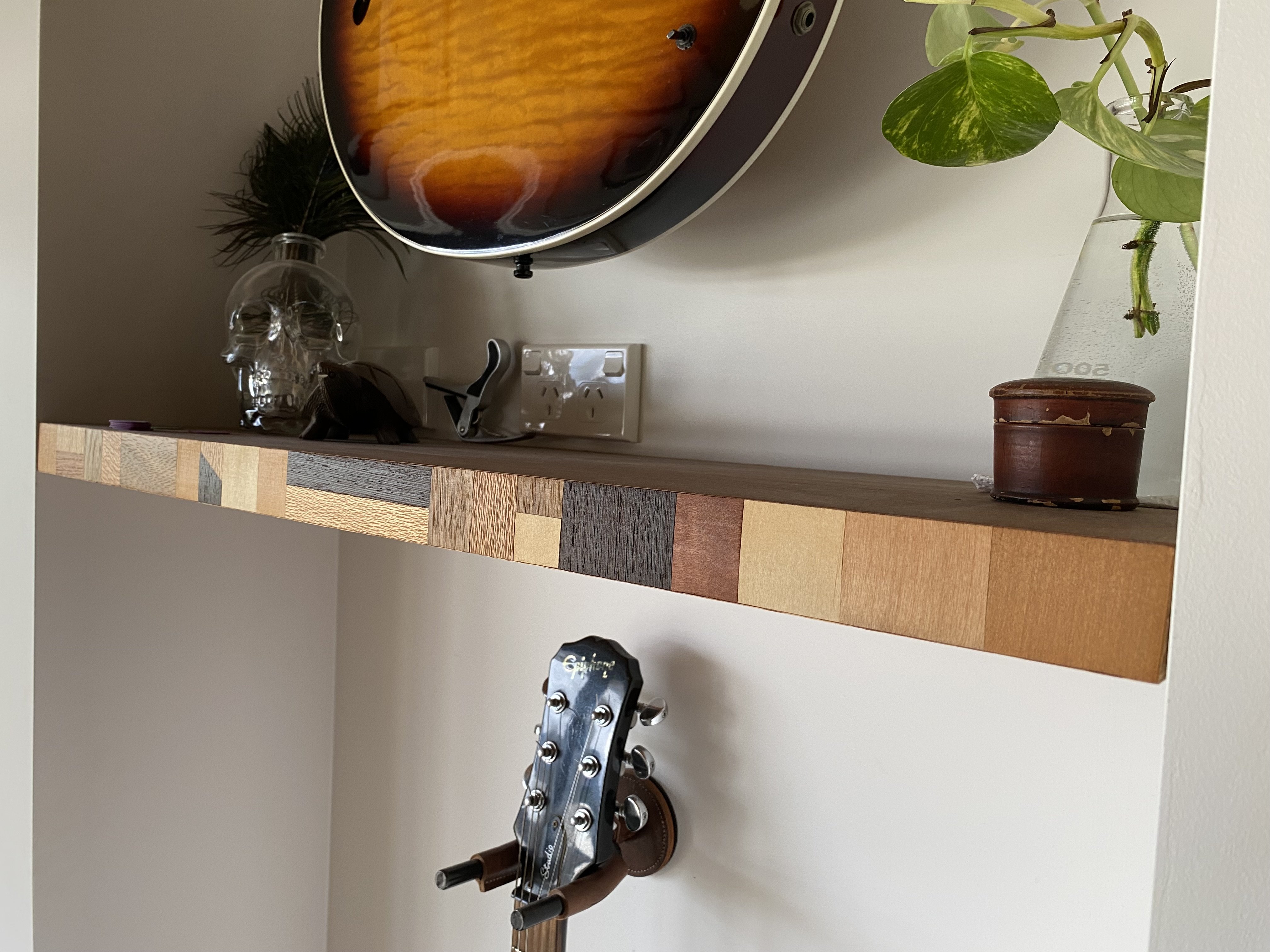
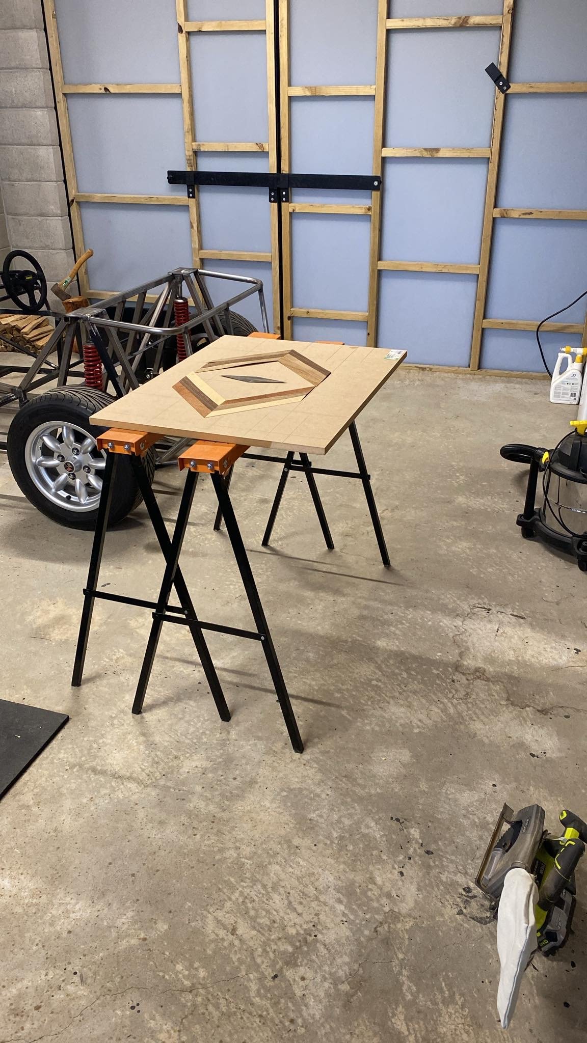
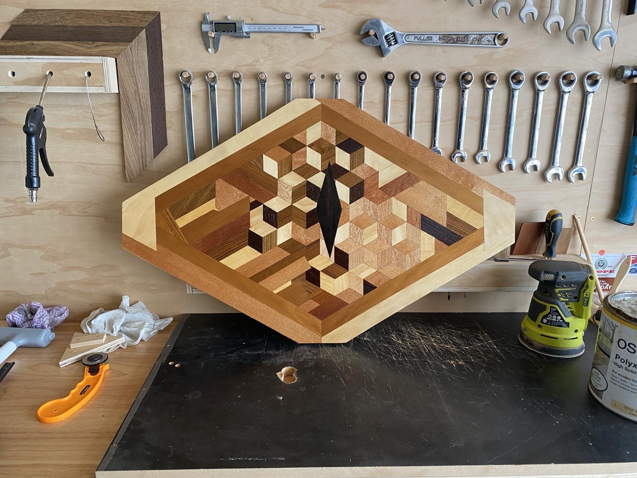
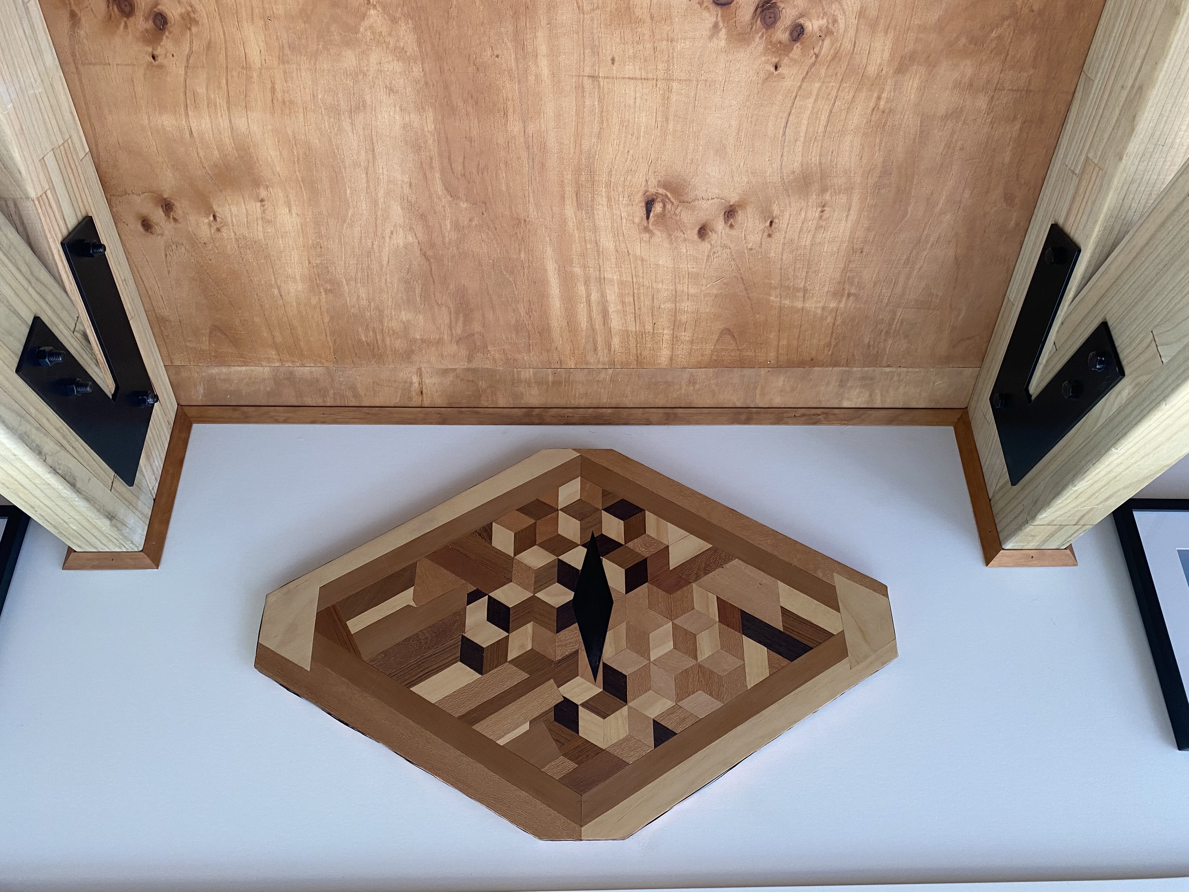
Few more recent veneer projects, I sanded and re oiled the door and made a pattern for the edge, as it annoyed me being plain when the door is open. Bit of copper tape to tidy up the edges. Because the door hardware needed to be adapted to fit with the larch cladding, the latch area was a bit ugly so I made a cover for it out of plate, complete with creepy stamp text Made a floating shelf out of 2 pieces of 18mm mdf glued together, then a patterned front edge/top and bottom. The purple piece is Totara, really beautiful when oiled. Tried out making some 3D cube designs, I wanted it to sort of look like a serpent eye, the pupil is made of ebony. I think I fucked with it too much and then cut the board down into a weird geometric shape, I wasn’t really happy with it initially but it’s growing on me. Enjoying learning more techniques and trying to get my joins neater
1 point
-
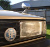
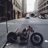
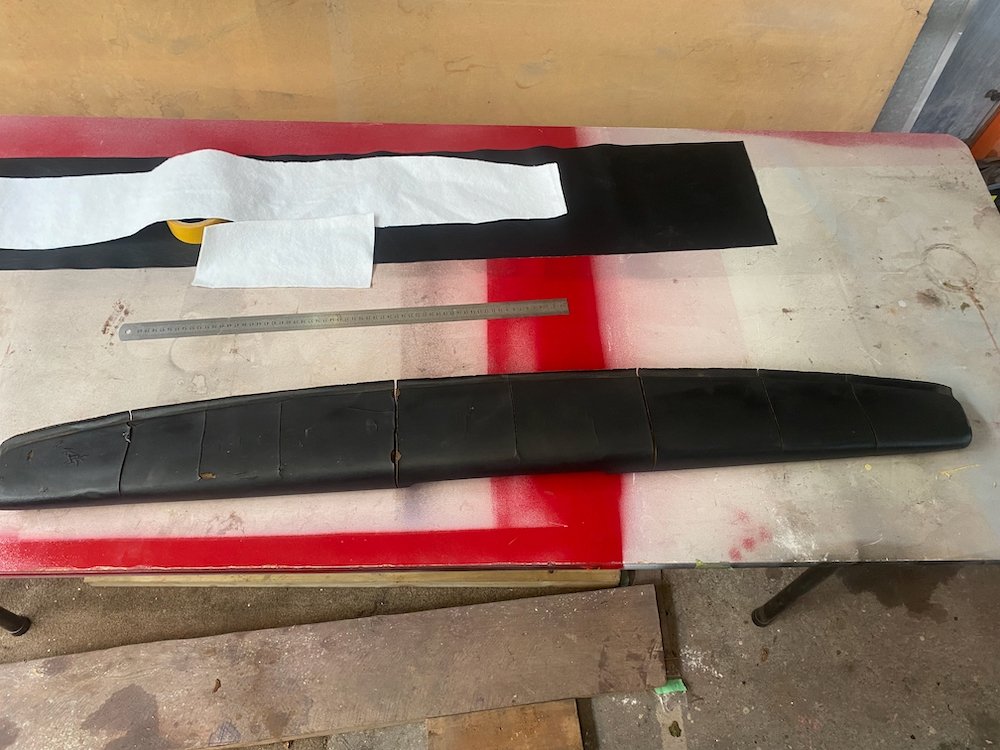
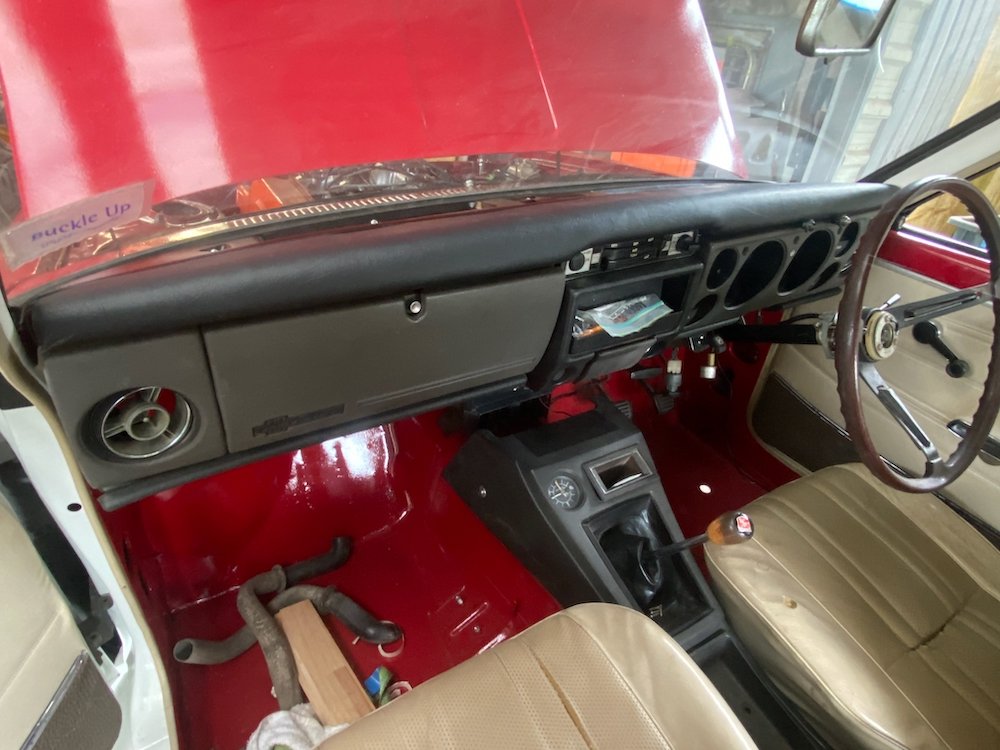
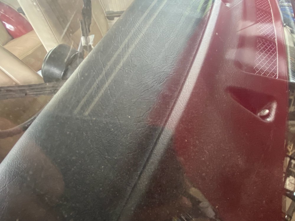
Interior polishing: Like most 50yo cars, the dashpad had cracked up pretty bad, long term i'd like to throw the check book at it, but in a budget friendly manner I called on my lovely GF and her knowledge of spotlight. We trimmed off the worst highpoints and double sided taped a layer of tablecloth liner to the pad, the idea here was the padding would hide the worst of the cracking once the vinyl leather was stretched over This was put on with the bare minimum of contact adhesive to keep the dashpad in close to original shape if needed for proper restoration further down the track. Finish result blends in well, of course the corners are a bit messy, but far nicer to look at than the old pad. Haven't been able to make a firm decision on the carpets but had an idea Chomp out some 7mm marine ply on the cnc, wrap in carpet offcuts from the 4wd.... Floormats that don't shuffle around.
1 point
-
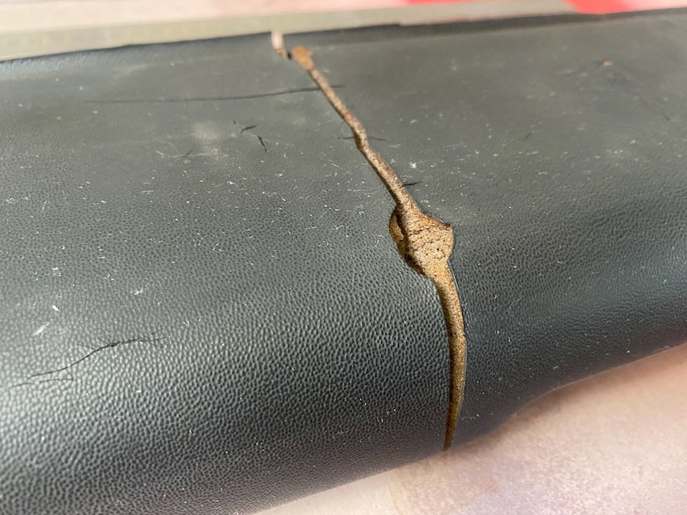
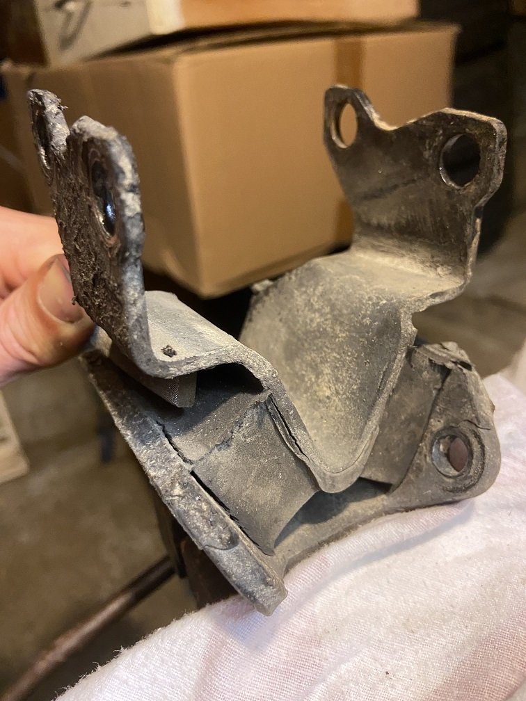
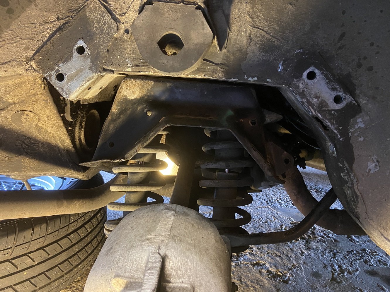
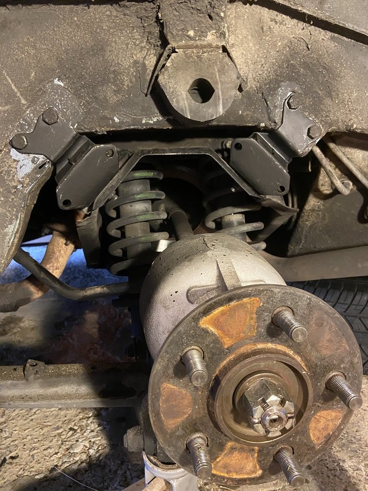
Boring update: I finally changed the rear subframe mounts. Here's the one I had been most concerned about. I had expected to find it in worse shape once it was off the car. Hardly worth worrying about really. This rubber-to-metal bond is the only thing that seems to keep the IRS assembly attached to the car. There is a radius arm connected near each rear hub which twists the whole IRS assembly in its mounts as the car leans in the corners, creating a passive rear wheel steering drunken snake effect. Wikipedia says this "...may result in significantly improved handling". May? Anyway, the mounts can fail from age or too many burnouts, and then you definitely won't have significantly improved handling. In this shot, the two subframe mounts have been removed: You can see the IRS cage thing, the tricky double shocks and springs, the light reflecting off the inboard rear brake disc, the skinny anti-roll bar terminating at the base of the RH spring (not present on all XJSs).... You can also see that I managed to change the mounts without disconnecting anything such as the exhaust, brake lines, roll bar, driveshaft, radius arm etc. I did one side of the car at a time, using a jack and an axle stand. New mounts fitted (this is on the opposite side of the car, to mess with your head): Now that these mounts are done, I'm not gonna be THAT guy:
1 point
-
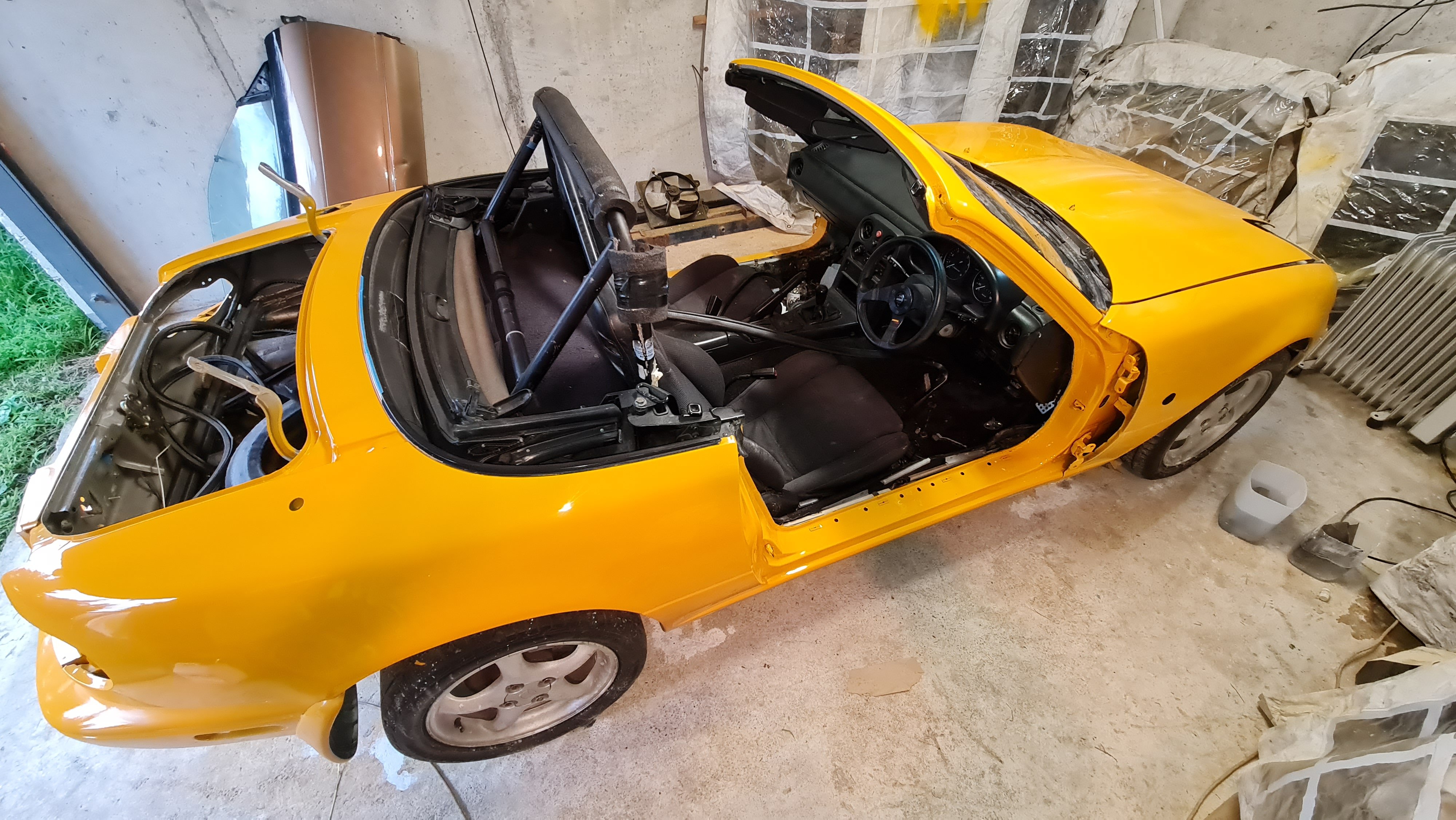
It's yellow! came out pretty good for my first time painting with 2k clear. On the day I had issues with the clear coat and it ended up quite orange peely. When I did the tests a few posts back it came out nice and flat, I think it must have been the temperature on the day. So I've waited a while and tested wet sanding and it's coming out great. Just an extra step I wouldnt have had to do if the clear went on better. Oh well I'll see how I go when I paint the doors and see if it comes out better. Really happy with the colour, it looks a bit more orange in photos.
1 point


This leaderboard is set to Auckland/GMT+12:00