kws
-
Posts
4,176 -
Joined
-
Last visited
-
Days Won
5
1 Follower

kws's Achievements
Committed (5/5)
12.7k
Reputation
-
More track day prep here. One of the common issues with the Toybaru Twins is that the oil temps are pretty high, so in an attempt to control it, I installed an oil-coolant heat exchanger. I'm not really breaking any ground here, since this exact cooler was factory fitted to the second gen BRZ/86, and others have fitted it to their first gens, but since no first gen got any sort of oil cooler from the factory I figured this was a good compromise for what I'm doing. Yes, ideally you would fit a proper oil-air cooler in the front with a thermostat, but 90% of my use is on the road, where it wouldn't be needed, and one major benefit of the heat exchanger for me is that because it sheds oil heat into the coolant, it can also suck that heat from the coolant, which is much quicker than oil to heat up, to bring the oil up to temp quicker when it's cold. Example of Greddy oil cooler (blue radiator) Cusco even released their own version of the heat exchanger for the first gen, which was a little more in-depth and required tapping into the actual radiator hoses. The basic theory is that the heat exchanger sits under the oil filter, and has coolant circulating through the inside of a copper core as the oil goes around the outside of the core. It's quite a nice looking unit. Genuine Subaru, of course. This is where it goes, under the oil filter. And this loop under the throttle body is where others have tapped into the cooling system, and where I will too I purchase a meter of 5/16" / 8mm coolant hose and used some spring clamps to fit it to the exchanger. Half a meter on each side is more than enough and will need trimming to fit nicely. I removed the filter, which was way too tight, and then had to go out and buy a deep 24mm socket in order to remove the old threaded stub, as this needs to be replaced with a longer one Slightly longer The exchanger comes with a new O-ring already, it just needs a smear of lube before fitting Clean up the housing, since you won't be able to access it again. Make sure the small indent on the right is clear of debris too, as the locating tang on the exchanger needs to fit in there Thread the hoses through under the AC compressor first, and then offer up the exchanger. Once it's sitting nicely, slide the centre stub through and tighten to spec (45NM) Oil up the seal on the new genuine filter and fit that too, Hand tight, no uggas or duggas. And now you can see what It's going to look like Now it's time to connect up the coolant side of it I removed the loop that is there from factory. Nothing came out of the top pipe, but a small amount come out of the lower one and proceeded to go everywhere, so I quickly measured, cut and clamped the hose on The top hose was measured, cut and fit too. I don't know if it matters which way the coolant circulates through the cooler, in my research from others doing this the consensus was that as long as it was flowing through, that's what mattered. Ignore the tape, its holding a piece of thick rubber in place to stop the hoses rubbing. Will be replaced with some split conduit later. I took the opportunity to change the oil too. According to the sticker, it was changed just before I got the car with Valvoline 5W30 (which is fine oil). Oil pressure was good, but I was surprised at how dark the oil was in just two thousand km or so. After much research, going over all the relative viscosities of oils at certain temperatures, I settled on Castrol Edge 5W30 as my oil of choice. It's thicker than the stock 0W20, but Subaru did recommend 5W30 for extreme use cases (like track days), and I don't want a thin oil breaking down on the track and costing me an engine. Once everything is buttoned up again, the fresh oil is in the sump and the coolant has been topped up, start the car and at idle with the heater turned to hot, slowly open the bleeder on the heater hoses near the firewall until coolant comes out of it. This should be enough to bleed the air out, but keep an eye on coolant temps for a couple of drives just in case. So far the results are promising. Previously, I was regularly seeing oil temps 10+ degrees C above coolant temp when at operating temperature, which would often mean oil temps 100+C. Now I'm seeing oil temps much closer to coolant temp, within a couple of degrees The oil temps also drop back quicker than they did before after a hard run, and the time for the oil to come up to temp on a near zero C cold winters morning is significantly quicker, maybe even halving the time. As a bonus, it appears I have picked up a couple of PSI oil pressure at operating temp, too. I was sitting around 10-12PSI at idle previously, now it's 14-16PSI. Over all, considering it cost about a quarter of a decent oil cooler kit, and unlike those it also helps bring the oil to temp, at the moment at least, I am happy with the setup. The big test will be at the end of the month when I take the car on the track. Hopefully it can keep the temps under control. I really gotta clean that... Parts Used Subaru 21311AA220 - Cooler Assy Oil Subaru 21317AA070 - Connector Oil Cooler Subaru 15208AA130 - Oil Filter Subaru 803916010 - Sump Washer 1 Meter 5/16" or 8MM Coolant Hose Please note these parts are specific to my car and may vary. Please check before ordering.
- 93 replies
-
- 13
-

-
As part of my prep for the track day later this month, I wanted to replace the engine mounts. How to do it wasn't exactly clear though. There is a bit of information out there for replacing the engine mounts, but mostly LHD and most of them say to remove the headers to do so. Being the stubborn guy I am, and not wanting to remove the headers, I thought there must've been a better way. In my last RHDJapan order, I got a pair of uprated STI engine mounts. These have a stiffer compound rubber without being super harsh like the Cusco and similar with their polyurethane mounts. With the car in the air I slid under, removed the two under trays and had a look at what I was playing with. The mounts were surprisingly accessible. That bolt and nut are easy to access with a rattle gun and extension, but there is also one bolt above the steering rack which is a little harder For that one I found it was best to start the bolt with an offset ring spanner as it is recessed, and then once loose, undo it with a ratcheting spanner Both sides worked with the same treatment To lift the engine, which has to be done otherwise the mount stud will not clear the crossmember, I used a floor jack on the sump. I'm not that happy doing this, but many people have done it before, and I used a rubber block to spread the load. I got away with doing this with no visible deformation of the pan. The hardest bit was just working around a big jack right where you need to be. I started with the RH engine mount as I figured this would be the hardest to remove due to the steering column/rack, and I was right. I completely unbolted the RH mount and loosened the centre stud on the LH mount so that I could use that mount to pivot the engine over (instead of just lifting it straight up and having nothing keeping it in place). Once the mount was free, I could move it around, but couldn't seem to get it out. The trick was to remove the heat shield plate on the top of it (not captive like the STI mount, it just sits there) and unbolt the steering rack (mark or make note of the bolt positions before undoing them as there is some wiggle room). Without the plate on the top I had more room to move and rotate it, and lowering the rack gave me just enough room to squeeze the mount out towards the rear of the car and remove it. It'll take a fair bit of rotating and wiggling to get it out, but it's doable. Refitting the new mount wasn't too bad either. Because the heat shield on the top of the STI mount is captive and can't be removed, I did get it stuck just as it went over the steering rack, but a little gentle pop with a pry bar got it free and into place. To bolt it in I lowered the engine slightly, so that the centre stud lined up, but I still had free movement to screw in the two bolts. Once the two bolts were done up hand tight, I lowered the engine down onto the mount, leaving the centre stud nut loose, and moved to the other side. Comparatively, the other side was easy since there was more space to work (no exhaust or steering column) Once the mounts are in place and the engine lowered down onto them, torque them to spec (45NM centre stud, 35NM for the two bolts, one of which has to be done to gutentight since a torque wrench won't fit - in hindsight with the rack loose you might be able to fit a torque wrench on an extension in there). The steering rack needs to be refitted and bolts torqued to 120NM. In conclusion, yes, at least on a RHD car, you can replace the engine mounts without touching the headers. How are the STI mounts? Good. The driveline feels tighter, more like it's part of the car. There is a small amount of extra vibration now, mostly at idle, but it's barely noticeable (and nothing like the vibration the Alto had after the rear mount inserts went in). I probably wouldn't bother replacing stock low KM mounts with them, but my 190,000km mounts were worth replacing. Parts Used ST41022AS000 - STI Engine Mount RH ST41022AS010 - STI Engine Mount LH Please note these parts are specific to my car and may vary. Please check before ordering.
-
If the transmission in your Toybaru Twin has ever been out of the car, there is a chance the reverse lockout plate on the shifter is no longer correctly adjusted and maybe impacting shifting. In my case I knew the previous owner had the transmission out for some work, and knowing it was quite hard to shift 1st and 2nd gears, I suspected my reverse lockout plate wasn't correctly adjusted. This is a reasonably easy task to do, albeit with the complication of having to remove the center console to access the shifter assembly. To start with I removed the shifter surround by gently reaching down into the shift boot, grabbing the inside of the plastic surround and pulling upwards on the front of it. The back slots in with a tab, so you need to start with the front. Once it lifts up, unplug the connector for the traction buttons, remove the shift knob, and the whole surround comes off. Next the little pocket in front of the shifter, with the start button, needs to be removed (or at least free'd and moved to the side). The manual says to just grab it from inside the pocket around the start button and pull, but I couldn't get that to work, so I removed the little side trim below the knee pad on the side (pulls free) and using a screwdriver gently pressed it against the back of the pocket and pushed towards the rear of the car until it popped. Both methods are offical ways to do it, according to the service manual This is a good time to unclip the handbrake boot by pulling it upwards and then sliding it off the handle. There are six screws holding the center console in, two under the pocket I just removed at the front, two behind the shifter and the final two are under the rubber mat in the "cupholder" storage tray area. With the screws removed, the console can be lifted, plugs disconnected (don't forget the one for the power socket) and the console removed. I slid it back into the back seat for enough room. Now its time to work on the shifter. Remove the big foam insulator on top, this has two white plastic screws on studs that need to be unscrewed and then remove the four bolts holding the metal boot retaining plate down. This will free the rubber boot and let you acess the reverse lockout plate I found mine was out of adjustment and too tight to the lever when in the 1st and 2nd positions. When going from 3rd to 2nd for instance, you had to push the shifter against the lockout plate, which made it harder to shift into gear and felt pretty yuck. The spec is a 1mm gap, when the shifter is in 2nd gear, and lightly held to the left (since my shifter has a little play in gear). I loosened off the four bolts securing the plate, just enough that the plate could be tapped into place but had enough resistance it didn't move freely and then slipped 1mm of feeler gauges in the gap, making sure the blades were parallel with the face of the shift lever "detent" (as the vertical stopper is actually curved) I then nipped up the bolts and checked the shift action. Mine was better, but if you find the gap too big, the manual says you can reduce the shim size by 0.2mm and try again until it's right. Also check it still blocks reverse unless the collar is lifted, and that you can actually get into reverse too. I used some lithium grease on the two faces and then reassembled everything. I'll tell you what, other than the Motul fluid in the transmission, this was one of the biggest improvements to shifting I have made. I didn't think it would do much, but it's significantly easier to shift into 1st and 2nd gears, and by some placebo, the rest of the gears feel smoother too. From factory this should, in theory, be correctly adjusted already, but obviously whoever reinstalled the transmission in my car just kinda set it by eye. Whilst my overalls were still clean I had a couple of other things to do in the interior. I have no idea what was going on, but the gauge cluster lens was junk. I'm not sure if someone had tried to clean it with something it didn't like, or if they had a sticker or something dumb on it at one point, but this is what I started with I polished it with PlastX and it got slightly better, but it was still hazy, particularly around the tacho It seemed the only way to actually cure it was to replace the lens completely. I did this on the Alto, and it was well worth the $30 or so from Japan. So I ordered a new lens from a GT86 (since the BRZ one appeared to be NLA) and set to work replacing it. The radio surround has to be removed, which just pulls off, and then the top visor needs to be removed. This is held with a single screw in front of the cluster, facing upwards, and then with a bunch of clips which require you to pull it up and toward you to remove. The cluster surround then pulls forward. This is attached to the column shroud, so I opted to just pull it forward instead of removing it. This left me with full access to the cluster lens. You don't need to remove the cluster. I just used a small flat blade to pop the clips around the perimeter of the cluster to remove the lens I took a lot of care not to touch anything inside the cluster, or to touch anything but the edges of the lens just so I didn't have rogue fingerprints everywhere. After reassembling, the results were dramatic Its crystal clear now. I think for the money, its one of the easiest ways to uplift the interior of an older car. You spend so much time looking through this lens, it might as well be spotless and not scratched or marked. Finally, the cabin filter was replaced. Fairly easy, just open the glove box and squeeze the sides in so the stoppers on each side pop out and let it drop down further The filter is behind the white cover. Gently press in the clips on each side and remove it Take note of the orientation and remove the filter. Mine was full of junk. Likely not changed since before it left Japan And slip the replacement filter in, oriented correctly (UP is up) Reinstall the cover, hook the glove box back in and job done. Enjoy the nice clean air coming through the vents. Parts Used Toyota SU00302619 - Cluster Lens Roadpartner 1PS961J6X - Cabin Filter Please note these parts are specific to my car and may vary. Please check before ordering.
-
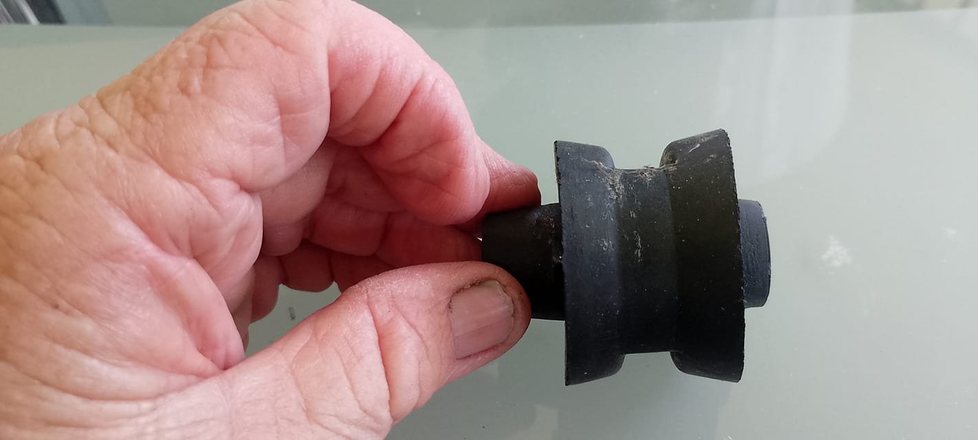
Problem with poly and similar hardness is allegedly because the bushes need to twist when the axle moves, if they are too stiff the cast alloy arm can actually break, and like the OE bushes, it's also long since NLA. It'd be easy if the inside of the hole where the bushes go was perfectly round, but it at least has the two flats inside it and i suspect it tapers in at the middle too, although I havent removed my bushes yet to check. I won't be modifying the arm to fit anything different.
-
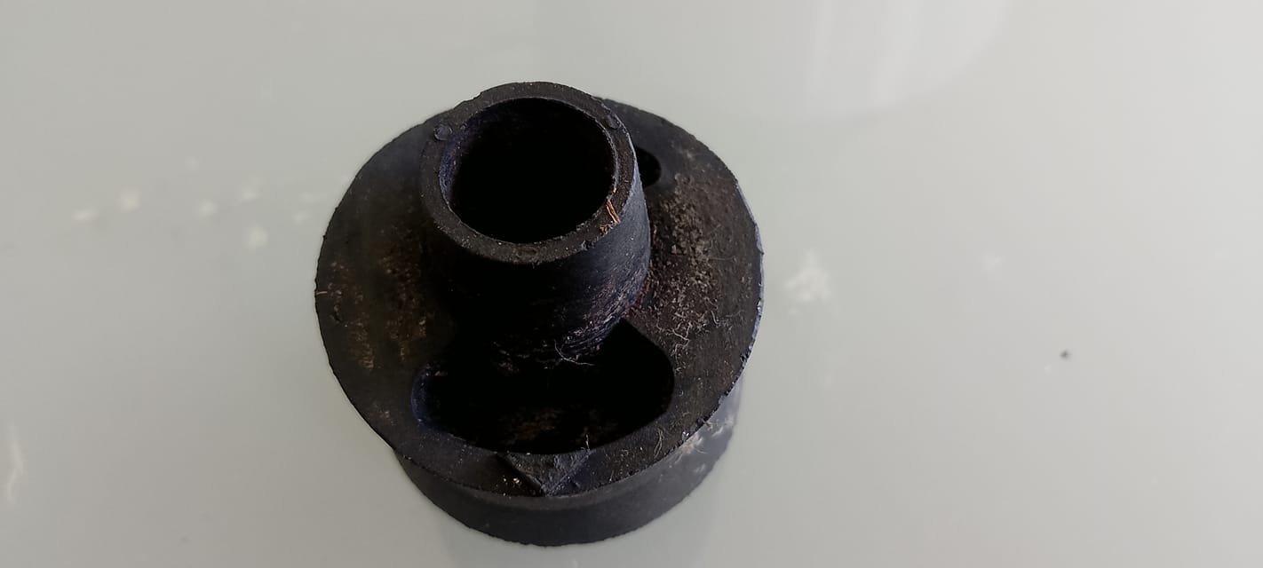
Bringing this back from the dead as casting my own bushes might be the only way to get bushes for my rear axle reaction arm since they are long NLA. Has anyone had a go in the last 5 or so years? I would want to cast them in a similar hardness to rubber, since it does need to flex and not be so rigid it breaks the arm (apparently a risk). The stock bushes are a weirdo shape, typically. The attached photo is what I need to replicate, and I could probably cast it in place in the arm if I needed, using some 3d printed moulds.

-
In typical fashion, my plan didn't work out, so now I'm onto Version Two of my oil pressure monitoring solution. I left off the last instalment with the pressure side of the gauge working, but I had not received the oil galley plug adaptor yet, so had not installed the temperature sensor. The adaptor arrived, so after work one night I quickly set about replacing it. I used a decent, firm fitting, 8mm hex socket on a ratchet to crack the plug. It has thread sealer on it and was in quite firmly. I originally fit the adaptor and then the sensor into it, but I would recommend fitting the sensor to the adaptor first and then screw the adaptor into the engine as it's easier to get it nice and tight and sealing well as one unit. I also noticed during one of my many times removing the sensor and adaptor that after the first install of the sensor into the adaptor, there were a couple of brass shavings that came out with the sensor, which is easier to clean out with the adaptor out of the engine. Anywho, the adaptor With the temp sensor screwed into it I crimped the terminals on the wires, and connected it up to the gauge (ignore the ugly tape, that is long gone) So, what was the issue? Well, temperature differential was my issue. I can monitor the oil temp with ODB2 in Torque, so it was quite easy to compare the gauge to what the engine was seeing Early on, when its cold, its fairly close But as the temps rose, the difference got greater. In the end I was seeing 10-15c lower on the gauge than in Torque I had heard that the galley on top can cause a difference, so swapped the sensors; oil pressure in the galley port, and oil temp in the front of the engine. It got worse Now not only was it slow to respond, it was miles out compared to ODB2. I suspect this is because the sensor was in the end of the long adaptor and no longer seeing oil flow, only pressure, so it was more measuring the ambient temp of the housing than anything. That was the final straw, a gauge that gives meaningless figures is useless. Oh, and it's bloody bright at night, even dimmed. With that failure under my belt, I looked around at my options. Annoyingly it seems pretty hard to find decent gauges, for a reasonable price, that have a PSI scale over 130PSI (my cold pressure). Normally I'm a diehard analogue needle gauge kinda guy, but I noticed with that one how hard it was to read at a glance and the accuracy was "maybe this much" at that low end of the scale, so I decided to try a digital gauge this time. I also scrapped the dual gauge idea and and settled on just a pressure gauge as thats more important since Torque can give me temperature for now (and I have an alternate solution in the works for temperature). I removed the galley plug adaptor and refit the standard plug, and swapped the pressure sender to the new one. It's a fair bit bigger than the previous gauge sender. Using the old gauge wires to draw the new ones through, I wired up the sender (albeit backwards in this photo, I forgot G is gauge, not Ground) Thankfully, it clears the stock airbox with plenty of room to spare And the new gauge. White during the day Dimmed and red during the night. It blends in very well with the stock gauges. Its a heck of a lot easier on the eyes than the last one too. It seems a little slower than the previous gauge to respond to changes, but it's a fraction of a second difference, really. You can see in the photos above that even at a glance it's super obvious and easy to see what the pressure is. Over all, I'm happier with it, and hopefully it'll give me some peace of mind when I take it on the track next month.
-
I used the term "veteran" as that's what NZTA calls "classic" cars over 40 years old, so when they check the NZTA site they don't get confused
-
Vehicle 1 - being a "veteran vehicle" in NZTAs books, will be reduced rego costs and is not subject to continuous licensing so you have two years of not being registered before it lapses. It cannot be driven on the road without rego either way. This site will give you the rego cost https://rightcar.govt.nz/rego/ Vehicle 2 - Buy 3-12 months rego, for the cost of the rego and away you go. Costs are in the above link. All the information is on the NZTA website.
-
We used to have this at a dealer I worked at, and it was amazing for cleaning wheels with baked in brake dust. Brutal and nasty stuff though, but my wheels went from a weird browny tinge that didnt wash off, to bright silver. Reading what it actually is, i'm surprised we were allowed to use it with zero PPE. https://www.pacer.co.nz/product-group/1806-mag-wheel-cleaner/category/285-wheel-cleaners
-
One thing I have been chasing since getting this car is backlash and thumping from the rear diff when coming on and off throttle or changing gear; I finally sorted it. Cleaning the throttle body and changing the gearbox oil had helped a lot in driving smoothly, but there was still what I would consider too much thumping and backlash in the driveline when coming on and off the throttle. Driving slowly in start stop traffic was pretty terrible. To try and combat this, I ordered two sets of inserts from Whiteline; A gearbox mount insert and a rear diff mount insert kit. I started with the gearbox mount insert. I was going to order an STI mount to replace the stock one, but decided on the Whiteline insert mostly based on cost. There isn't much to it, it's literally a moulded piece of polyurethane that gets installed in the mount, to take up the voids in it. The instructions call for completely removing the cross member and mount, but the internet said I could install it much easier with just some careful jiggery-pokery, and the internet is never wrong. This guy here is what we are working with. The insert goes into the gap shown by the arrow, which allows the insert to take some of the weight/force, instead of just the two blocks of rubber either side of it. I found since my mount has about 190,000km on it, it had compressed enough that I needed to jack the transmission up, this was done with a bottle jack and a couple of blocks. I did have to remove the rear black undertray to access the bottom of the transmission. This is the only bolt you need to undo to fit the insert. It goes through the bottom of the mount, to the flat square block of metal in the above photo of the mount - Its kinda T shaped. Once the nut is removed you should be able to push the whole bolt upwards by hand. This is how you slip the insert in. I jacked the transmission up until I had ample space in the mount Thoroughly grease the insert with the supplied grease and then using one hand to hold the T bolt up and out of the gap in the mount, use your other hand to slide the insert into place. Orientation of the mount is a little unclear, if the Whiteline wording should be visible from the front or rear, but as far as I can see it makes no difference, and I've seen others install it both ways. The instructions say to "slide the insert into the rear of the mount". Slip the centre bolt down through the insert, lower the trans down, refit the nut and then torque it to 40NM. To stop the T of the bolt twisting, I jammed a flat blade screwdriver in between the metal and the side of the mount. Job done. Quite easy to do when you don't need to drop the whole crossmember. I'm not sure why they say to. While in the area, the next part to install was the FactionFab rear shift carrier bush. This is another polyurethane replacement. It's a big, solid unit and comes with new bolts The old mount is held in place with two bolts. To gain better access, since it's a bit limited up there, I removed the two bolts off the driveshaft hanger bearing, and let the shaft droop down. This gained me just enough wiggle room to get a spanner up there and undo the bolts Using two hands, one on either side of the mount, wiggle and pull it backwards to remove it. It's a tiny little thing compared to the replacement. The rubber is very soft. Grease the spigot on the end of the carrier, and then wiggle and slide the new mount into place. Refit it with the two new bolts, bolt the driveshaft back in, and you're done. The difference in these two changes was quite noticeable. More direct shifts, less play in the shifter, and much better feel. I think most of it was the mount insert, but the carrier bushing can't hurt to do. Moving to the back of the car, I had high hopes for the rear diff inserts. These, like the gearbox insert, are designed to fill voids in the stock mounts and stiffen them up. The kit includes two inserts for the rear mounts, and two sets of inserts for the two front mounts. These are the front mounts, bolted vertically up to the subframe And the two rear mounts (foreshadowing...) I started with the front mounts. Using a jack I took the weight of the front of the diff and removed the bolt from one side The first part of the insert is a ring that slips over the top of the mount. Remove the metal cap sitting on top of the mount, pop it aside, and then offer up the ring. This needs to be worked slightly so that it hooks under the centre of the mount and wraps over the side. The ring is the shiny black part between the diff and subframe. Don't forget to refit the metal cap on top, this kinda just sits there in place, on top of the ring. Next is to fit the lower insert. This pushes into the centre of the mount and has two notches in it that locate on the protrusions in the bushing. The lower plate will locate in the bumps on the insert. Rinse and repeat for the other side, and that's the two front mount inserts done. Now, the rear. This is where it all turned pear shaped. First, remove the rear swaybar D bush mount brackets so you can move the swaybar to get more room This should give ample space for removing the bolts on the rear mounts. Do one mount at a time. I started with the RH one and soon found an issue. The bolt was really deeply recessed into the mount. I removed it and noted how weird the mount looked. It wasn't what I was expecting. There was zero chance that the insert would fit, the whole design and shape of the mount was wrong. Going by the paint pen X under it, I suspect the car failed compliance on a bad bush when it arrived in NZ, and to get it through the workshop fit whatever bush would fit the hole. It looks a bit like an IS200/300 bush from my googling, but definitely not the right one. It should look something like this, on the right, fitted to the subframe Anyway, the LH bush looked fine, so let's do that one. I removed the two bolts, greased the insert up and slipped it into place The alloy plate goes on and the bolts refitted. After torquing the bolts up, this is where I left it, since I couldn't do the other bush until I sorted a solution. The solution ended up being me ordering a new genuine bush from Japan, knocking the incorrect bush out, and fitting the new one with the insert. Easy, right? The bush arrived quickly, so the BRZ went up on axle stands New genuine bush and correct bolt The mount is vastly different from the currently fitted one I knew I wasn't going to be able to get the new bush in with the muffler fitted, so that had to be removed first. The bolts were a bit crusty, but heating them up nice and hot with a heat gun, soaking them in CRC and then a couple of ugga duggas got them off without issue. Unhooked from the hangers and removed. Tons of space now. I removed the swaybar mount brackets again and removed the centre bolt from the bad bush. Classic Bunnings bolt, a little different from the correct genuine one. I wound the new bolt into the diff, just to check the threads werent damaged. All was good, so it was hammer time. I'll tell you what, spending about 1.5 hours under the car swinging a 1.5KG hammer upside down above your head with limited room, is probably one of the worst jobs I have done in a long time. My arms are killing me now. I was using a combo of 1/2" extension bars (which will never be the same again) and a couple of long bolts, to hammer on the edge of the bush. There isnt a heck of a lot of room around the diff to access the bush. After many whacks, the bush finally started to shift The problem was that because I could only access one half of the bush, it kept trying to come out cocked on an angle and then getting bound up. To address this, I actually removed all but one of the bolts in the rear bush of the diff, which I loosened, and then lowered and shifted the diff across. This gave me more access to the other side of the bush. With the extra access, I managed to get the bush out straight to a point where I couldn't drift it out any further due to the inwards facing flange on the subframe. The trick here was to move to the other side of the subframe and start hammering the bush sideways back and forth. A few good whacks and the bushing just fell out. Comparing the two bushes, well, yeah. No wonder the diff banged around like it wasn't supported... it kinda wasn't; all the force would be acting like a big lever on the bush since it was only supported at the very outside edge of the bush. That bush couldn't have been doing anything once some torque was applied to the diff. The correct bush supports the diff through the whole length of the bush. Refitting, in comparison to removal, was very easy. I lined the bush up in the hole, with the locating arrows facing straight up and down, and then using a mallet knocked the bush home until the centre tube was touching the diff backplate. Using a ruler, I checked the bush was square in the subframe and tweaked as needed. And now, I could finally install the Whiteline insert for that bush. What an ordeal. Everything was torqued as per the Subaru manual As a slight side note regarding the front inserts on the diff, I had heard these can introduce gear whine at certain speeds, and unfortunately I can confirm this was the case. Having them fitted introduced a noticeable gear meshing whine at a couple of different road speeds, mainly around 70KPH and 100KPH, which sucks, since that's where most of my commute usually is. You would get used to it, but I hate noises like that, so opted to remove the two front mount inserts completely and only run the rear bush inserts. The result is no more gear whine, but most of all, the thumping, banging and backlash from the rear diff is gone. Finally, everything seems to be connected together, and it's a lot easier to drive now. I can't be 100% sure what was the inserts and what was just having the correct bush fitted, since I never drove the car without the inserts and the good bush, but either way, I'm happy. If they had just fit the correct bush in the first place, this job would've been done and dusted ages ago, but no, previous owners have been living with it like that and thought nothing of it. As a little bonus, it would be rude to have the rear muffler removed and not start the car, right?
- 93 replies
-
- 10
-
-
what sort of merc, is it old enough to do some Pick A Part lego?
-
Going a full circle into a Marina again. KwS's 1973 Morris Marina Coupe.
kws replied to kws's topic in Projects and Build Ups
Well, that's it, it's been six months, which means the WOF on the Marina has run out. So what did we get up to in that time? Not much. I covered around 150km total in that time, but other than some mishaps, the smiles per mile were high. One thing I had been looking forward to, after British Car Day, was a grass Motorkhana run by the local MG Classic Car club. It's close to where I live, and fairly low stress since it's on nice smooth grass. It'd be a treat for the Marina for being so good. Before then I had a couple of small things to sort. The main one was the valve cover gasket which had been leaking down the side of the head, onto the exhaust manifold. Not ideal. Quite easy to do. Whip off the six bolts on top From there, the cover just lifts off, revealing the pinnacle in 70s OHC technology After a good clean, a new gasket was fitted and the cover went back on I also replaced the fuel filter as I'm still running into issues where its filling with old fuel sludge from the tank. This was from just a couple of times driving it. Not as bad as the last filter, its not blocked, but still a lot of sludge. Before replacing the filter I wanted to try something; draining the tank through a filter and seeing what comes out. I fitted a new filter, rerouted the outlet of the pump into a fuel can, via a funnel and grips... And powered the pump directly from my jump pack I drained about 15L out of the tank, until the pump started to suck air, before hooking it all back up to the carb, refilling the tank with the fuel I just removed, and changing the fuel filter again. This was a new filter. It's not as bad as I thought, but still quite a bit of sludge. With another new filter fitted, a fresh 20L of fuel in the tank, we were ready to go A couple of weeks ago the Motorkhana rolled around, so I got up nice and early, bundled the tools into the support car and head off. Lots of awesome cars in attendance, and a bunch of great people too. Before long, we were queuing up ready for the first course. This was one of three courses set up for the day. Here I am, ready to tear it up Being one of the first cars through, the grass being very wet, and my first time ever doing something like this (let alone in a Marina), my times were... slow. Even with my complete lack of power, traction was non-existent. I got a pretty darn slow time, but who cares, I was having fun! I lined back up for another try This time the ground was a lot more torn up, less grass, more mud. Traction didn't improve... I went into it with a bit more vigour this time Still slow as heck, but went for maximum flair. The world's slowest steering ratio doesn't help when things get a bit crossed up, it feels like it's a million turns end to end That run looked like this from outside the car Leaning with intent Definitely slightly sideways I was having a darn good time, sliding the car around in the mud, even if I was way off pace. Having done that course twice now, I wanted to move onto the next one and see what that was like. I was inching forward in the queue of cars, waiting my turn. All was going well. Too well. The car was running great, the temps were good, everything was working. Until it wasn't. I pressed on the clutch pedal to move the car forward and bam, suddenly my foot was on the floor. Dammit. The clutch slave cylinder again. You can see me gently tapping the pedal to see what the state of it was. Last time this happened I stomped the pedal to see if it was jammed, this resulted in all the guts of the cylinder being ejected when the force of my foot pushed the piston out through the circlip. I didn't want to do that again, So I was careful not to press too hard. Thankfully my battery was fully charged, my starter a trooper, and I was on grass, so I could turn the engine over in gear and get it started, which allowed me to move the car off the line and back to the parking area. After popping the bonnet I could see what had happened, the large main circlip that retains the slave cylinder and stops it sliding backwards away from the clutch lever had decided to yeet itself and was no where to be found. Thankfully, the rest of the slave was still intact. Myself, my wife and a couple of other competitors had a good look around for the circlip, but it never turned up. As far as I know, it's still there, sitting in the grass. Broken or not, It's still a cool car After scrambling around for a bit, we eventually jumped in the support vehicle and shot home to see if I had a spare circlip. I did not, and could not get one on a weekend either. Damn. So, what does one do then? Zipties. All I needed was enough clutch to do a couple of starts at intersections on the way home, I could start it in gear to leave, and rev match the shifts without the clutch on the drive back. I secured the slave in place with 6 large zip ties, pulled as taught as I could given the space. We knew when the entry gates were being opened, so we left a little early. Starting in gear, and leaving it in first until I got to the gate, as its all low speed shared public access At the gate, waiting to be let out The drive home was fairly uneventful. The clutch worked, with a couple of pumps, for the once or twice I needed it, otherwise I kept it in second for maximum low speed grunt and with some creative route-taking, managed to get home without having to stop for traffic and avoided too many intersections. To my amazement, despite the heat down in that area, the zipties were all still present when I got home, albeit they were softening up as the clutch was barely working by the time I pulled into the garage. I'm not disappointed the car let me down, not at all, you have to expect things like this when pushing a 50+ year old car that until recently had been off the road half its life. I'm disappointed I didn't get more time out on the grass, doing sweet skids. I'm more impressed though that even though it broke, it still got me home under its it power, with nothing but zipties to fix it. Through the day the Marina attracted a lot of attention, particularly when the bonnet went up, but everyone was very positive and loved seeing it out there. There were offers of help, tools and one guy even offered to shoot home and get a metal detector to find the clip; none of which were needed, but very much appreciated. The whole community around entry level events like this is awesome. Once I got it home, I looked at my options. I could convert it to the UK style cylinder, which is a different shape and doesn't rely on a circlip to retain it, it uses the body of the cylinder, so it physically can't fail in the same manner. These are available ex UK, but are a pain to fit and I have already rebuilt my current Aus cylinder, so that'd be money down the drain. I decided to give the Aus cylinder one more chance. This time I grabbed some callipers and got measuring. It turns out when buying external circlips, you measure the body of the shaft its going to go on, not the groove it sits in I ordered some 35mm stainless external circlips online And after struggling with circlip pliers to fit it, the slave was once again back where it should be, less the zipties I did wonder if the fact the cylinder had been painted when it was rebuilt had anything to do with it. The circlip groove had paint in it, so before fitting the new clip I used a wire brush to thoroughly clear all the paint out of the groove. I'm not sure if the old circlip was wrong or just old and tired, but it was a very loose fit compared to the new one. You could almost fit the old one by hand, the new one takes a bit of force and work with circlip pliers to get in place. The clutch pedal feels a little firmer now, but that could be a placebo. I took the Marina for a really good, hard, run over some twisty back roads near home and the clutch seems to be operating 100% fine now, with no signs the circlip wants to jump off again. I will call it a success for now, but keep an eye on it (and a spare clip and tool in the boot). That brings me to today, where the Marina now has no WOF and cannot be driven on the road until it is renewed. I have chosen not to renew the WOF for now and will instead take the car off the road over winter. During the last check, I had an advisory for the bushes on the rear diff reaction rod being perished, so that will be high on the list of things I need to do, but there is also a reasonably big list of work I would like to complete before its back on the road, one of which is upgrading the suspension, and I plan to get the twin carbs on too. Heck, If I get around to it, the door cards need trimming too. So, here we are again, the Marina is off the road, but with a clear plan in mind. We will be back, better than ever, ready to do more KM than the last WOF period, and next years Motorkhana.- 80 replies
-
- 22
-
-
The final lot of work in the week since I bought the car, was to sort out some shifting issues Since I got the car, I had some drivability issues. I've previously mentioned the throttle and clutch response being an issue, but the gearbox also shifted pretty badly. There is history of the gearbox having been rebuilt not long after the car was imported a few years ago, under warranty, due to a "whine in 3rd gear". I confirmed with the workshop that did it that yes, it's been rebuilt, but no they didn't retain any info on exactly what was done. It's fine when driving, no whine now, but the shifting is pretty crap for a box that people rate quite highly. When cold it's very hard to shift, and when warm pretty much every gear is notchy to shift into, and often crunches. There is also a fair bit of play in the shifter when in gear. After extensive reading, I concluded that the gearbox fluid needed to be changed, and I wanted to try the uprated shifter springs to see if they made an improvement. Other than money, I had nothing to lose trying this. I ordered some uprated shifter springs and three bottles of the recommended Motul Gear 300 75W90 gearbox oil The car went up on the Quickjacks, for my first look under it. Over all, it's very clean under there with minimal concerns. All the suspension bushes appear to be in serviceable condition. I started with the shifter springs. To access the gearbox I removed the rear under tray (the black tray, not the silver one), which is secured with a whole lot of 10mm bolts There are two springs, one either side of the gearbox This one uses a 10mm hex. There is VERY little room to get this one out, so you will have to use a hex key, not a socket. I had to dig deep through my roll cab to find this as I normally use sockets or my big hex keys which had no chance of fitting. The other is easier to access Both were very tight. I guess when they were refitted after the rebuild, on the bench, they were done to FT (F'n Tight) instead of NM. They had also been refitted with good old grey RTV, which was a pain to clean off. That second one uses a 27mm socket, and is a lot easier to access if you have a flex head ratchet. I had to use a cheater pipe to crack this one Yay, sealant Remove the springs (the one behind the 10mm plug may need a pick or magnet to slide it out) and replace them. Refit the plugs. There is a lot of talk online about cross threading the big one in the photo above, but just take your time to refit it by hand. Put some pressure on it, rotate it backwards a couple of times, and then it should wind right on in by hand with minimal effort. I couldn't get the torque wrench onto the 10mm one, so did that up gutentight by hand, and used the torque wrench on the 27mm one. With the springs replaced, I located the drain and fill plugs on the side of the gearbox Which are both 10mm hex. I cracked the upper one and then removed the lower drain plug to release a torrent of thick and quite dark fluid. The level was right, and no chunks came out, but the fluid wasn't pretty. I cleaned the small amount of sludge off the drain plug magnet, replaced the crush washers on the plugs (18x24mm alu) and refit the drain plug. I started to refill by using the nozzle on the bottle, but ended up sticking a pump in the bottle and pumping it in to the gearbox as it was quicker. After about 2.2L went into the box, and it started to trickle out again, I refit the fill plug. A quick clean with brake clean, and we were done. I refit the under tray, and lowered the car down. Up top, I replaced the battery. The sticker indicated that it had been replaced at 56,000km in 2017 (Heisei 29) The cranking was quite slow, and I really didn't want to get stuck somewhere. I whipped the old one out And stuck a nice new one in. Shame to lose the cool blue Subaru battery though Cranking is much faster and more powerful now. While under the bonnet, I also enlisted the help of my wife to bleed the clutch. It's a weird system on this, where I couldn't one-man bleed it. If you push the pedal down with the bleeder open, it didn't push fluid out, you have to pump the pedal and hold it down with the bleeder closed and then open it to release the fluid. The pedal also gets stuck to the floor due to the helper spring. I definitely got some air through the hose, and the clutch does feel a bit less vague now. So what's the verdict? Well, It's like a new, better, car. The throttle body clean I mentioned in my last post made a massive, completely unintentional, improvement. I can only presume the throttle plate was getting stuck closed and opened once a sufficient amount of angle/motor torque was dialled in by the pedal (usually around 15-20%), snapping it open. Now it opens straight off the pedal being pressed, and the response is significantly better. I no longer use the throttle controller to dull the pedal response, I may even start using sport mode. Secondly, the gearbox fluid completely changed the feel of the box. No longer is it stiff and hard to get into gears, it's a lot smoother, but all the notchy and crunchy shifts have completely gone. It went from a gearbox I legit thought was on its last legs, to one that's pretty good to use. Not MX5 (or Alto) levels of accurate and smooth, but much better. The shifter springs have also taken out a lot of the in-gear play in the shifter, which makes the selection of gears more accurate and it no longer sort of wobbles into gear, occasionally being blocked by the gate. There is still some play, but it's no longer an issue. The combination of these fixes means I no longer bunny hop and jerk away from a stop, and it's made the whole driving experience much more enjoyable. And finally, the last improvement until the next lot of parts arrive, new tires and an alignment. I knew the rear tires were bad; the previous owner warned me one would need replacing for a WOF, and the other was new, but mismatched, from having a puncture. The fronts, appeared fine. Knowing I was going to want to drive this car spiritedly, I ordered some Bridgestone RE003s, in the stock 215/45R17 size. I can now confirm you can fit a full set of four in the car. Today, I dropped the car in for the tires to be swapped over and an alignment. I'll tell you what, I'm glad I did. First, the front tires were also trashed. They're cheap ditch finders, but it turns out the inside edge of both were chewed down to the secondary rubber, so they're no good. One rear was also worn down on the inside edge. The fronts One surprise to me with the old tires was how soft they are. After handling the RE003s which are quite a firm carcass, the cheapies have no structural integrity at all. The sidewalls squish under the weight of its own mass, and the belts in the tread just sink down if you apply any pressure. The alignment explained it all though; the excessive wear, the weird tracking, and the shaking when driving. That's a heck of a lot of front toe. The RH front was 4mm toe out, and the LH front was 2.2mm toe in, basically driving like this / / but with one side pointing right almost twice as much as the other. I could do with some front camber though... Driving down the road now, I could immediately feel the car was smoother. I didn't realise it must have been shaking or something at lower speeds too, as it feels different even around 50kph. The steering is more responsive and no longer wanders down the road. Of course, I had to break in the new tires, so a quick drive over a local hilly road was in order. Suddenly, after all this work, the car finally felt cohesive and like it was all working together, not trying to fight itself. It feels very good to drive now, and I'm finally bonding with it, instead of just liking it, seeing the potential in it, but being annoyed by how it feels. I still need to clean it, but here are a couple of quick photos with the new rubber
- 93 replies
-
- 18
-
-
Yes, you can check on the Subaru Japan website, and this one has had both recalls carried out.
-
Next on the list of things to quickly knock off, I wanted to install a proper gauge to measure oil pressure and temp. I had planned to install a temp gauge in the Alto but never got around to it, so knowing that the BRZ would be seeing track time and I wanted to monitor it, I looked into my options. I wanted something clean, simple and easy. The solution came in the form of an Saas Dual gauge It's really designed for oil pressure and coolant temp, which is a weird combo, but there is no reason it should have issues reading oil temp. I ordered a gauge and a couple of adaptors to mount the sensors on the FA20. The next question was how to mount it. I wanted it subtle, and not sticking up in a pillar mount or something. Searching around, I came across vent pods, which allow you to mount a gauge in the right-hand dash vent, which seemed like a nice tidy way to do it. I found one on Thingiverse and tried to print it on my ancient old printer, which didn't go well. Thankfully, a friend has a much better printer and kindly ran one off his machine for me I quite like this design as it still allows for airflow through the vent instead of completely blocking it. To install it, the dash vent just pulls out. Stick your fingers in the vent and grabbing the outside edge, give it a sharp pull As a small note, it fits back in with the large bit of the surround facing the cluster. I marked the top of mine to make it easier to refit without guessing which way it goes Once removed and on the bench, the front ring just unclips As does the retaining ring behind it Now the vent flaps can be removed The vent pod insert was a smidge too small on the outer diameter, so I wrapped some tape around it to make it a snug fit I used some foam tape to pad the back of it out too After a quick scuff with some scotchbrite to dull the gloss, I reassembled it all Now for the less fun part, the wiring. I knew the under dash wiring would be easy, the option connector has everything I need, but getting the two sensor wires from the engine bay through the firewall was going to be a pain. To power both the throttle controller and gauge from the option harness I needed to make a Y splitter, so I whipped one up For the sensor wiring I chose to go through the main grommet, using the add-in tube thing I snipped the plugged end off the tube above the main wiring harness And using an old coat hanger, I fed the bundle of wires through You'll want to use a zip tie to seal the tube around the wires once you're happy with their length. I ran the wires to their relevant locations on the engine. I haven't received the adaptor for the temp sensor yet, so I have just bundled the wires up where they need to go, but I could fit the pressure sensor. That big round plug is where the temp sensor will go once the adaptor arrives. I'm going to tee into the factory pressure sensor here, on the front of the engine To access this, I removed the intake pipe and air filter housing A ton of room with that removed I fit the adaptor and the two sensors This location gives heaps of room to clear the air filter box. The wiring for the stock sensor sits well below it. Before refitting the intake piping, I removed the four 10mm bolts from the throttle body, removed it and cleaned it. It was caked in black sludge. I wedged the throttle pedal down and used brake clean and a rag to thoroughly clean inside it. With the intake reassembled, I moved to installing the gauge into the dash. I ran the wiring through the vent, plugged the gauge in and pushed it into place. There is a bump on the LH side of the ducting behind the vent, this gave me room to feed the wires out without cutting into the ducting. I pressed the ignition button and it all lit up A quick first start to make sure it all worked and check there were no leaks. Pretty good pressure when cold. Without the temp sensor, the digital readout just sits at zero. Good oil pressure when warm too. This is at 89c oil temp Once the temp sensor is fitted, I will rely more on the actual gauge rather than Torque, but it'll be interesting to compare the difference between the two. Hopefully this will let me catch any potential oiling issues before they become a problem.