
Leaderboard


Popular Content
Showing content with the highest reputation on 04/21/24 in all areas
-
As per the title this next stage of building the exhaust silencer/muffler/back box/ take your pick has taken much more time and effort than I had always expected. I started by taking the blue imp apart. To Woolf valley garage I went.... ..where I removed (rusty mild steel) exhaust, bumper and rear valance.. Popped it onto rusty imp shell... Now I knew exactly how much room I have to play with. Whatever I was going to build had to work with several things. I wanted the box to be mounted higher than the existing one behind the Datsun engine as I was sick of scraping it on steep driveway exits. It had to be built completely of stainless steel, no exceptions. No more corrosion. It had to look tidy and fit within the bumper line, tailpipes excluded. The tailpipes were to be twin centre exit. I had a very specific look in mind and they have to be just right. It had to be quiet enough and yet still sound sporty. This last one is tricky and will most likely need modifications to get right hence the last design point... It has to be modular, easy enough to disassemble and repack with sound deadening (most likely glass fibre) Now I knew the size I could build it to I started by making some flanges. This so I can unbolt the flexible sections between the V clamps and the box. Made to suit the 44mm tube as per the tube off the V clamps. Lifted the big folder we'd made onto the bench top and folded up some 1.2mm stainless. Although heftier than I could have used I've gone with this thickness to helped avoid the tinny sound thin stainless boxes can make. I wanted perforated stainless tube but couldn't find any within NZ. Got some perforated sheet instead - again 1.2... Which I cut strips from and formed up into tubes as such... Welded... Now I had the start of a box and some tube. I could sit down and nut out a design. I have had some basic ideas for ages on how it might look inside but it was really good to sit down and see how it might work. Drew some ideas up.. Nutted out something I think would work well and be easy enough to change if need be. Time to commit. I had to cut some blue steel. First actual act of modification to the imp in my quest to plonk a flat six in it. Now I could double check box sizing and weld the flanges in place. Folded up the second box side.. Complete with captive nuts to suit a lid.. Tail pipe time. I almost went with twin 2" exits but they were just a tad too big. Settled on twin 45mm. Tacked them to yet another stainless pair of flanges to work with the modular design aspect. Happy with the look I then fully welded them on the inside. The flanges will be sealed with a soft copper gasket. Happy I had the look right I cut the centre top from the box, created a recessed bit and carefully welded in the second threaded flange. So now I have inlets and outlets where I want them and just have to connect the dots. Ideally a nice long a route to dampen sound while keeping it as smooth flowing as possible. Plus, as per original brief, it has to allow for easy disassembly and re-packing. There was quite a bit of head scratching with this bit of the build but eventually I sorted a design out. I cut various bit of sheet and put big holes in them with a nice brand new holesaw set. Made little boxes with more big holes... Shaped bits like a heart...(#putmyheartandsoulintoit.....) Welded the ends onto the main box, curved in bit to help with flow and also hide the external bobbin mounts from view a little. Now I had a collection of parts that would come together and form a london underground of tubeways for the exhaust gases to follow. I was pretty happy with the layout for its potential silencing effect. However I now wondered if it might just end up being a touch too quiet and restrictive. Luckily I had come up with an idea early on where I could add some valves. Quite a little bit of extra work involved but the more I'd thought about it the more I was convinced it could work well. With this in mind I had built the middle chamber width to allow for some valves and made sure they could be removed to fit said valves in place. I cut some 44mm holes in the middle chamber lids and made some to valves to suit... Whipped up a little press form to create brackets.. Valves mounted. Underside of lids have the heart halves which help direct flow from one tube back too the next, or up and out through the open valves.. Valve shafts stick out through back of box. Sealing will be by a combination of spring loaded fibre and silicone washers. Now for an exciting point in life that every shed 'Barry' looks forward to. Emptying out those boxes of little random fittings that have been stashed away 'just in case you might need them'... Such fun! I selected my (stainless!!!) treats and scribbled on some alloy. Made lots of alloy swarf.. Ended up with these levers. Pinch bolted to the shafts along with added grub screws. The short length of threaded rod will be changed for a long length of stainless rod, actuation method from within the car yet undecided. Possibly a 12volt door lock motor etc or maybe mechanically with a bicycle cable. Recessed the backs to allow for seals.. So yeah. Lots of parts! Compulsory photo of thing exploded into many bits... All together now with some arrows. Remember each side is just a mirror of the other side (there is a small cross over hole in the centre plate that separates the sides) Valve closed... Valve open... I think it'll be quite a difference in sound and look forward to hearing it. Valves can be seen in action in this very exciting video... So It's pretty much complete except for the mount points which I'll do once I've got some bobbins from engineering shop along with seals. The lid will be sealed by running a bead of silicone which I'll let set before clamping the lid down. Oh I weighed it too. I was worried it might end up quite hefty but it will be only about 6.4 kg once all the bolts are in/packed with fibreglass.. The box will be painted satin/matt black leaving the tailpipes shiny. Silencer mounted in place... View from above showing plenty of room for the valve linkages in place. I ended up cutting a tiny bit more of the valance away so there's room for a stainless heatshield. I then covered the valance with some masking tape to help prevent it getting too scratched while I put back in some internal strengthening and capping it all off. I'll also be adding mount areas for the bobbins. I'll remove the engine next and add in the big multi-pin connector to the engine loom. Then I'll be seriously very close to removing the Datsun engine and cutting out the under seat area just as I have on this rusty shell. Wow!!23 points
-
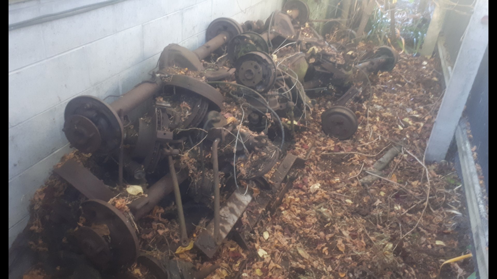
Believe it or not i worked on this today. I went over to mums to sell a valiant diff to a rooster off marketplace. While i was there i set about refitting the copper radiator. With a view to giving the block a good flush before fitting the purdy new rad. I got that in. But decided there wasnt enough day left for the actual flush. (We spent ages digging through my pile of diffs, turns out i have three spare VG diffs) I went to start the old bitch up, cos i havent heard it run for ages. But the fuel pump didnt seem to be able to fill the fuel filter. So i gave up on that too. Ill take an electric pump over some time, and finish what i started today. Pic of the pile of diffs for thread.
 12 points
 -
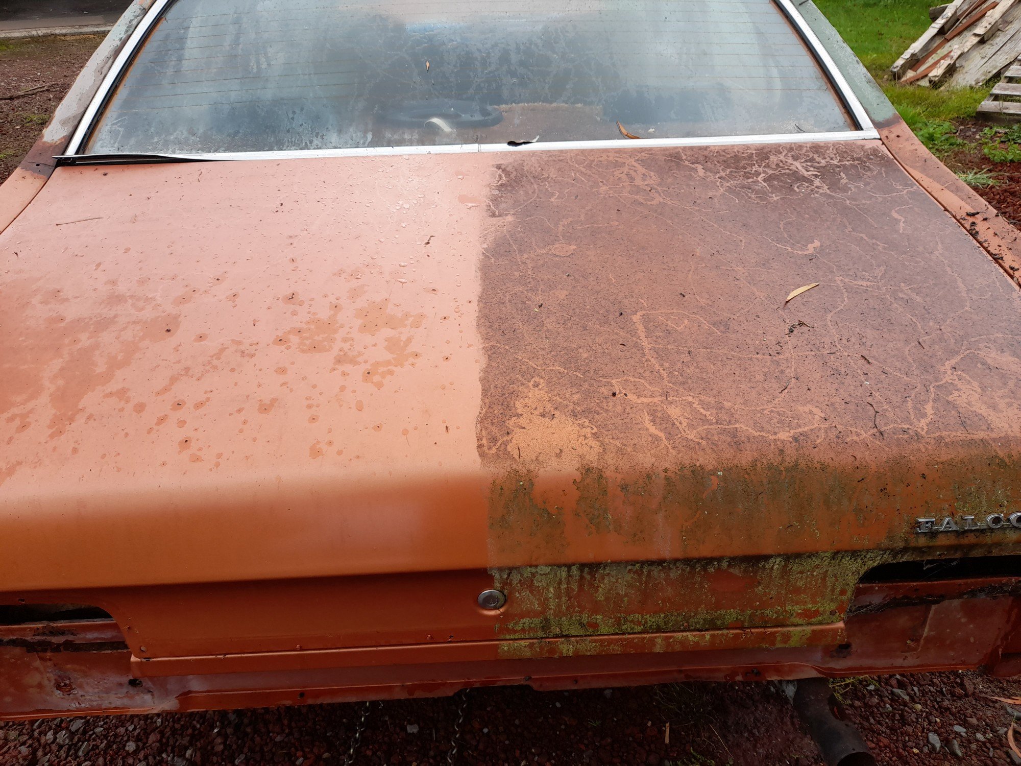
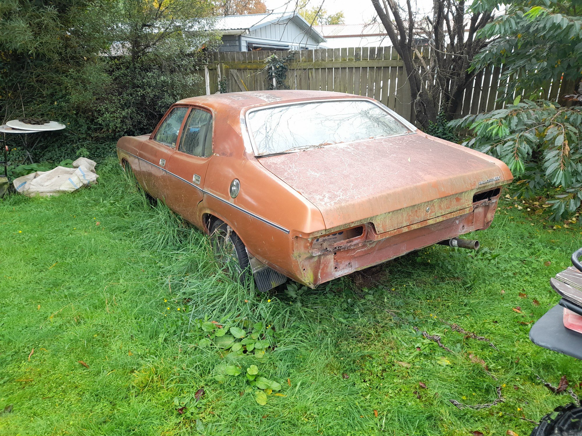
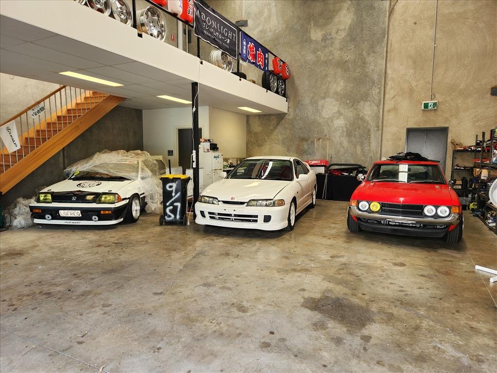
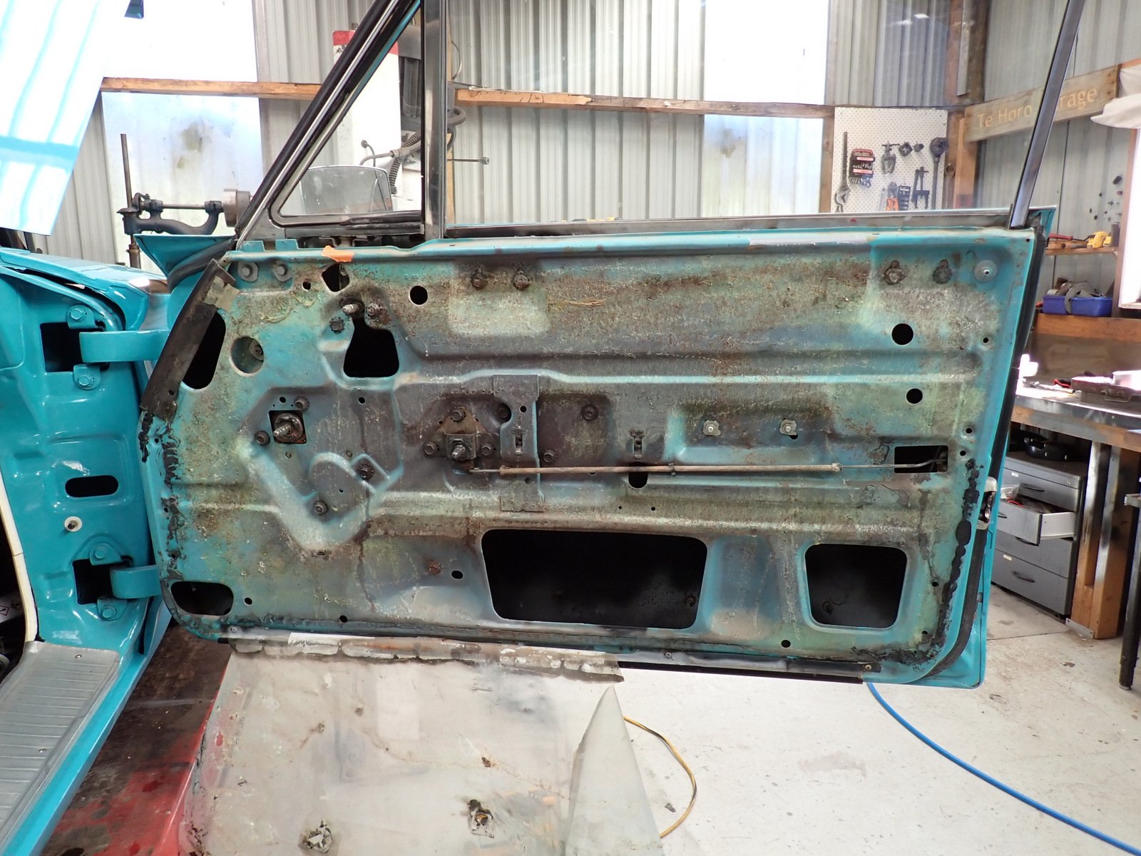
Today went pretty smoothly, managed to solo tow the old girl off the lawn and onto the driveway and waterblast 2 years worth of lichen off. Found lots of cancer had spread but not as bad as it could be. 15 yard test is still a pass. Also found lost of lifting bog from its life before me, will make for interesting times ahead. Had to use the quad with a bare tire on the front to push it into shed as the brakes were binding on, got wife to steer it and it went slowly rolling into the jack, axlestands and compressor. She hops out 'i tried using the brake but it didn't work, its not my fault!!' Calmed her down with 'if i told you it had no brakes would you have hopped in it?' Prolly no dinner for me tonight lol.
9 points
-
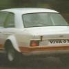
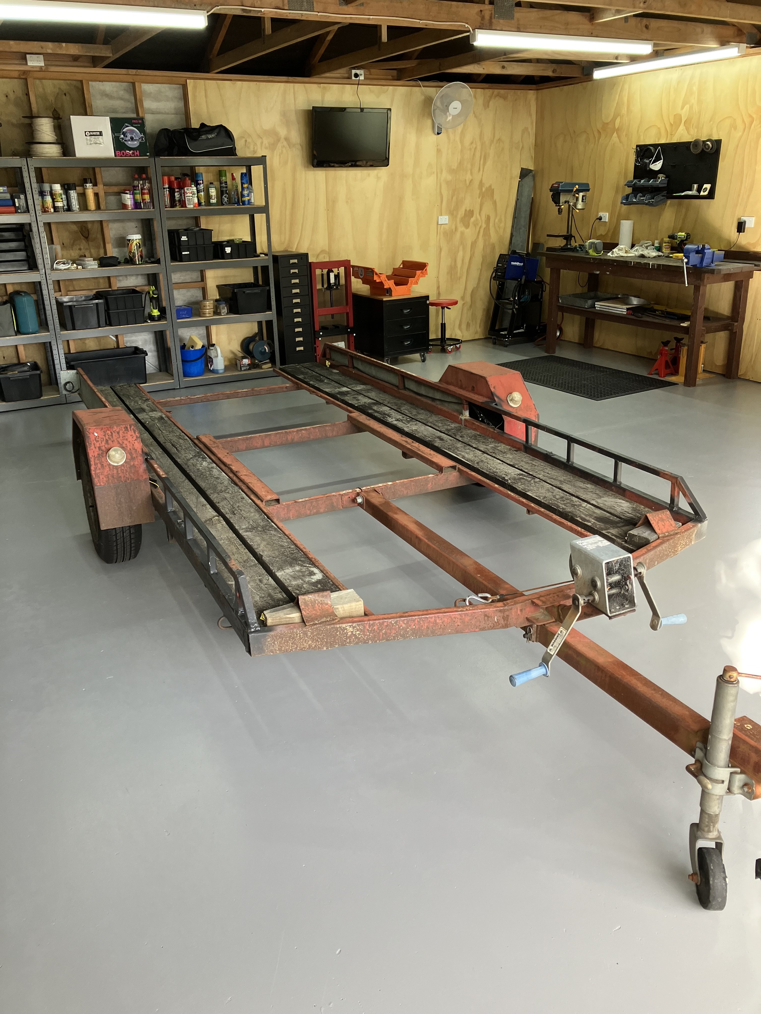
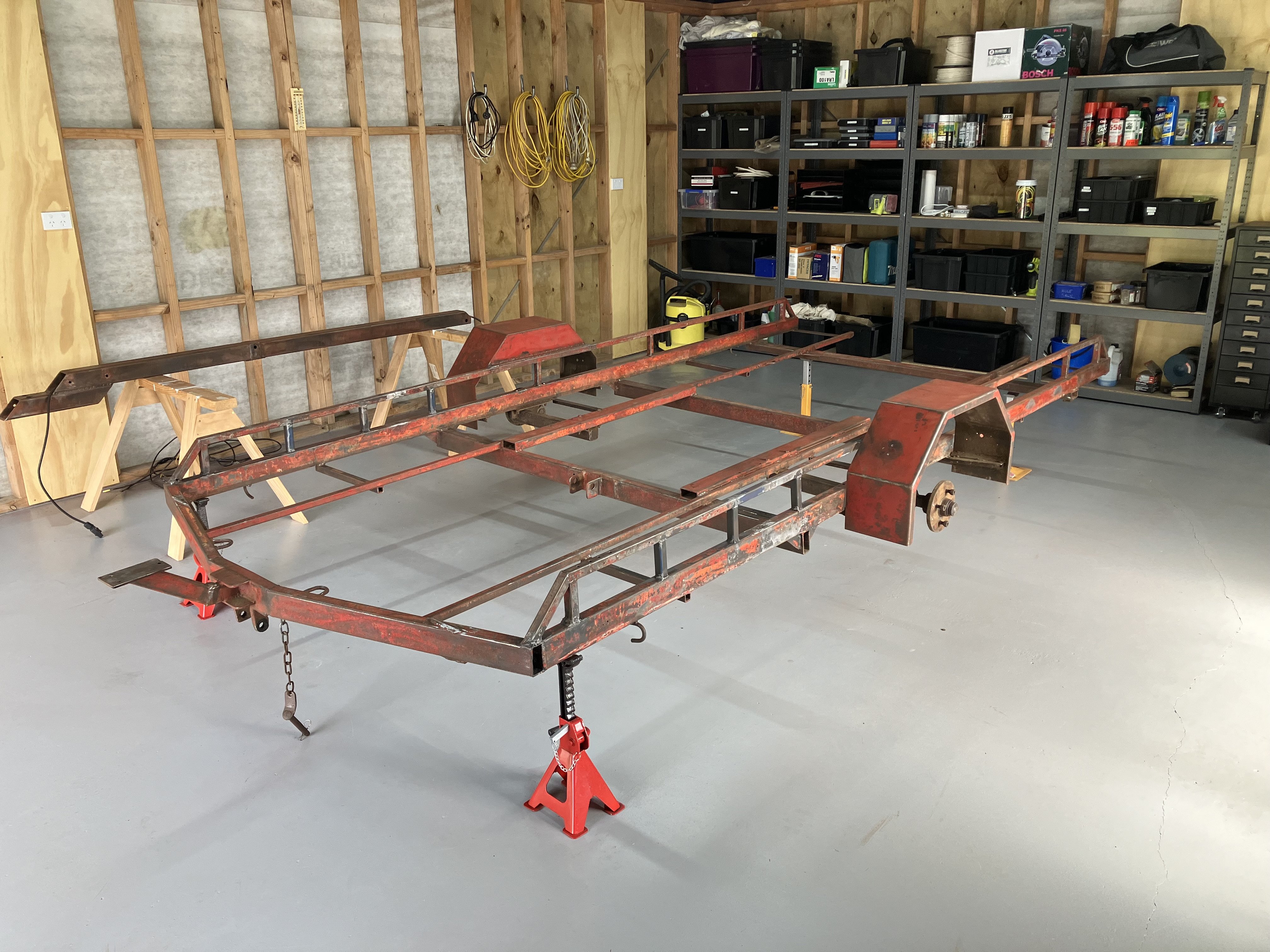
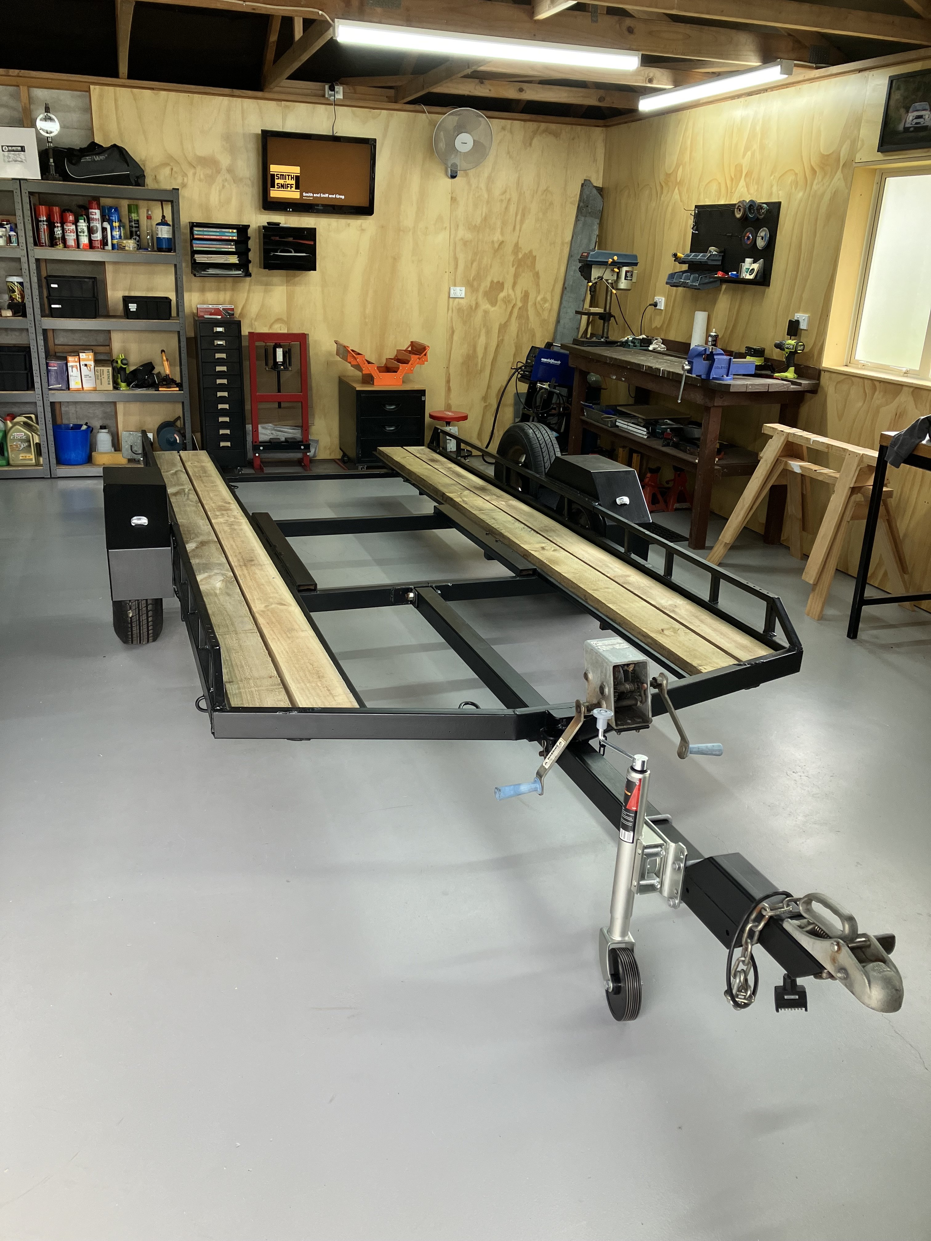
This is kind of random project thread worthy. So I’ve owned this old single axle car transporter for over 20 years (apart from a short period where a mate owned it, then I bought it back). In about 2005 I gave it a rough wire brush and painted it tractor red and put a new timber deck on it (necessitated by a mates Fiat 131R almost falling through the rotten old deck). I’ve been meaning to give it a refurb for ages, but it kept passing wofs and just looked like shit. It progressively got worse until @azzurro borrowed it and it had some structural failures where the spare wheel mounted (coincidentally while also towing a Fiat on it). He kindly patched it up before returning it but it needed attention. After moving back up north I decided it was time to tackle it and strip it right down and give it a birthday. Fix a few bad welds. Paint, new electrics, new deck etc. Anyway. After a few solid weekends of work it’s just like a new one. P.S. if you want to buy it, hit me up. It’s only small (suit Viva, 1200, Escort, Starlet etc).
9 points
-
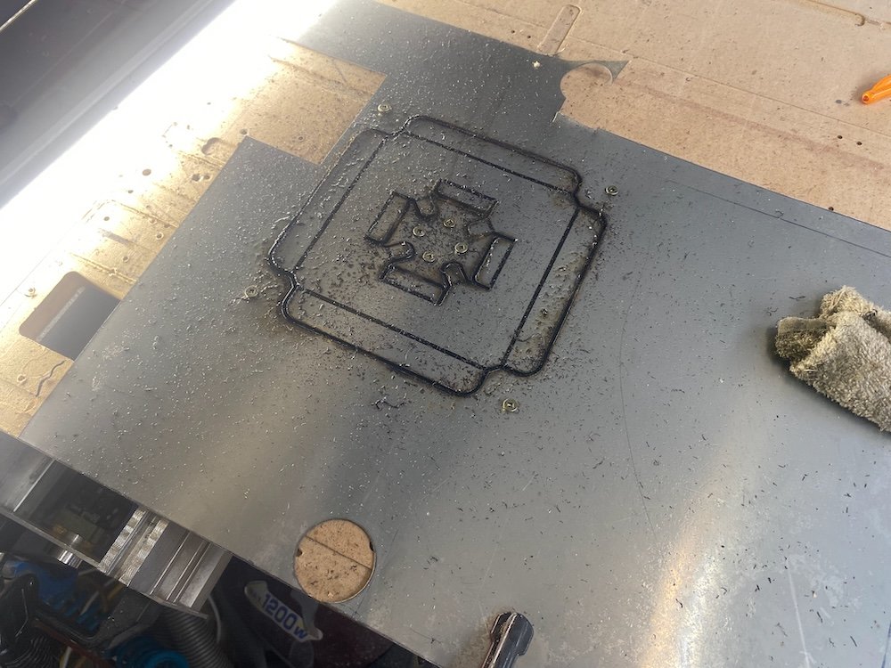
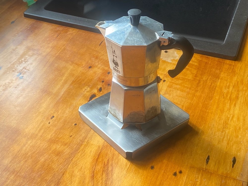
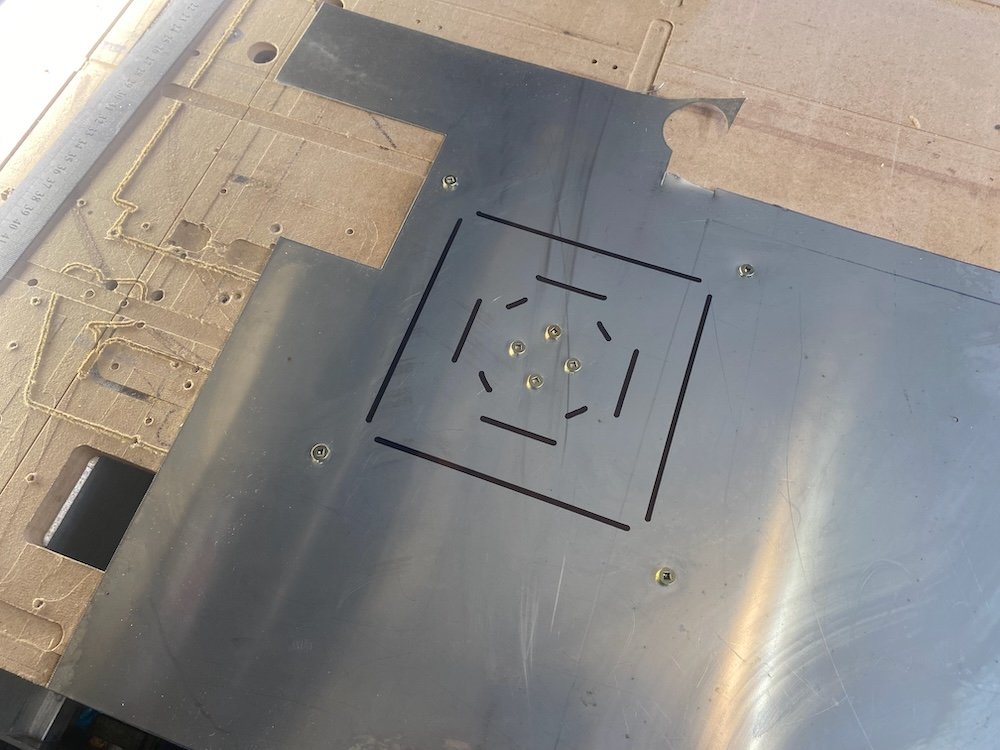
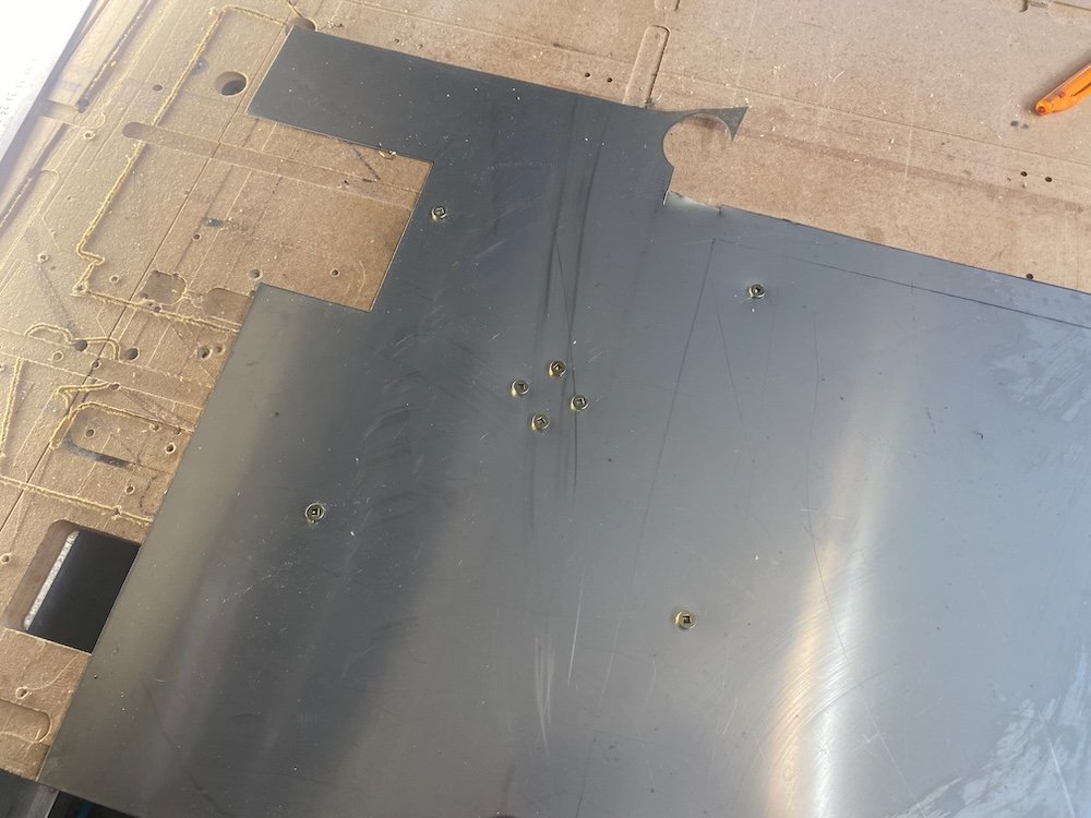
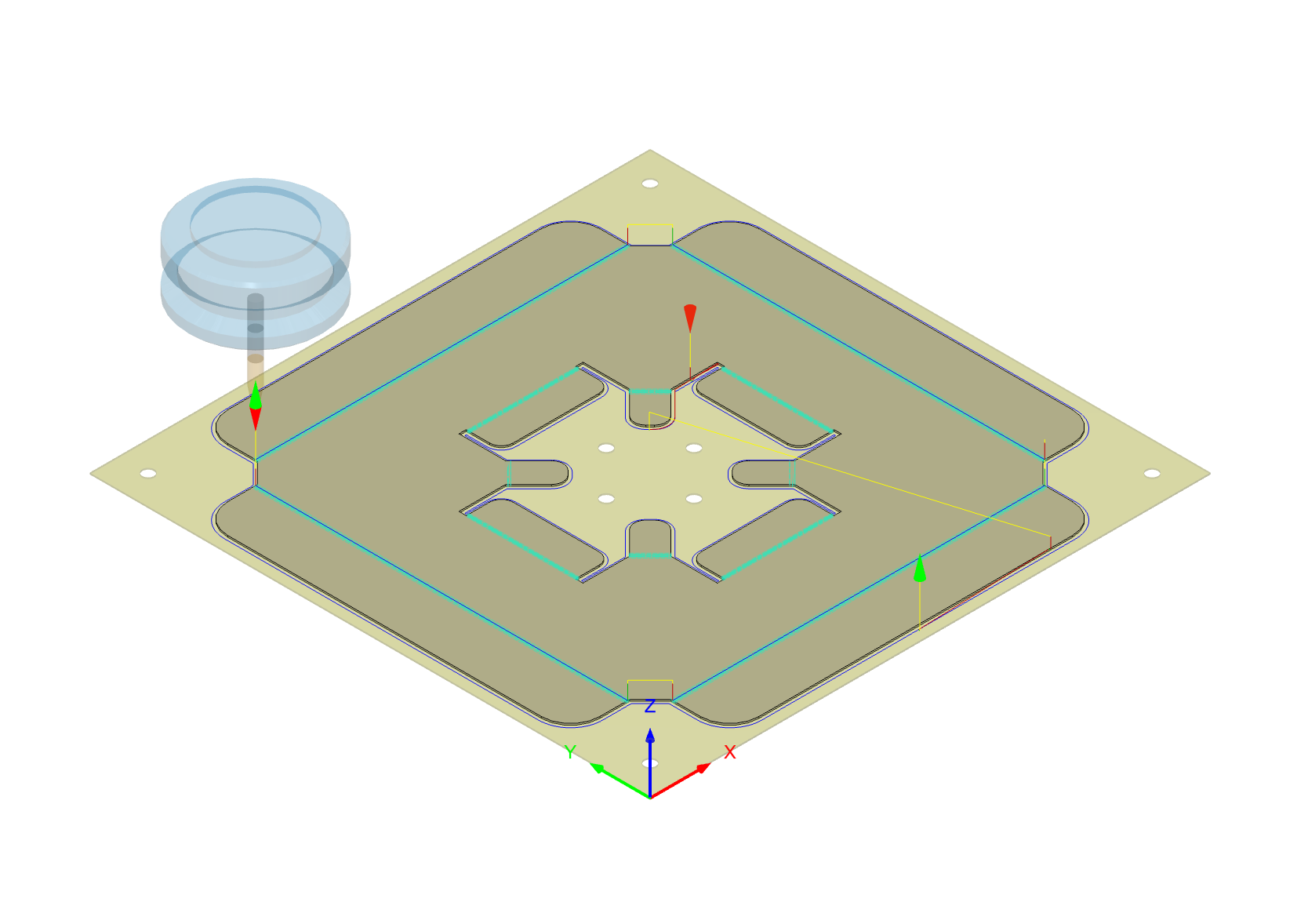
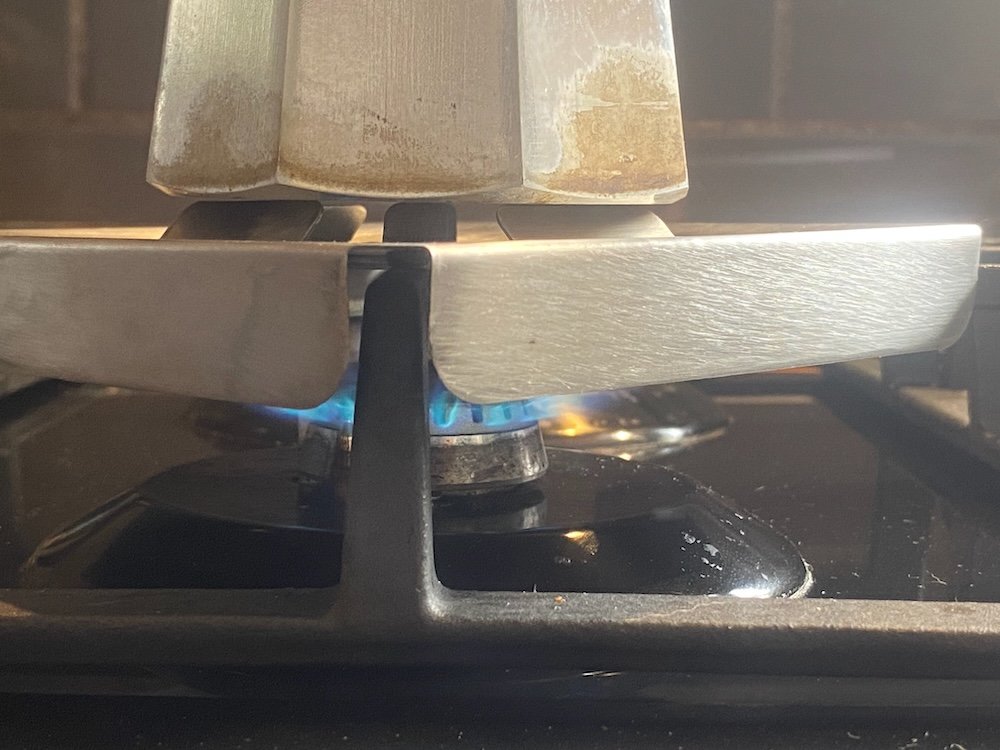
Coffeepot only just fits on the gas cooktop and disasters have struck, a few solutions have been tried but didn't really work, a stainless sheetmetal idea has been floating around in my head that holds the pot up and directs the heat to the pot but with only basic cutting tools I never managed to get far, having just managed to get my cnc router running on sheetmetal, this was a golden time to put a brew on. As @ajg193 asked about my process, I've taken a few photos along the way. First up draw a sheetmetal part and create toolpaths in Fusion, I also make the stock as a seperate body so the machine can place workholding holes in useful places: The idea of this design is the smaller tabs project off the cooktop grill to support the pot while the skirt and larger tabs direct the heat. First machine op, g clamp 0.55mm sheet to the bed and drill 4mm holes: Second op draw fold lines: And finally cut out: This was bit of a disaster, personally I hate working with stainless but I also want coffee, now! Knowing plenty of coolant was compulsory, I got ready with a can of crc, of course this turned into a flame thrower after 50mm of cutting and by the time I hit stop the cutter was toast, I gave it more cutting depth to shift to undamaged flutes and went back to the messy option of heaps of cutting oil, the mdf spoil board was getting pretty smokey by the end of the cut but we got through. Clean off the burnt mdf, add some folds and done: Test run confirms the idea works, but I think improvements are possible. Turns out the tabs didn't quite like the weight once the heat came on and I think a change to the wider tabs could maximise the surface area for heat transfer....... Well, at least the pot won't fall over so easy now
8 points
-
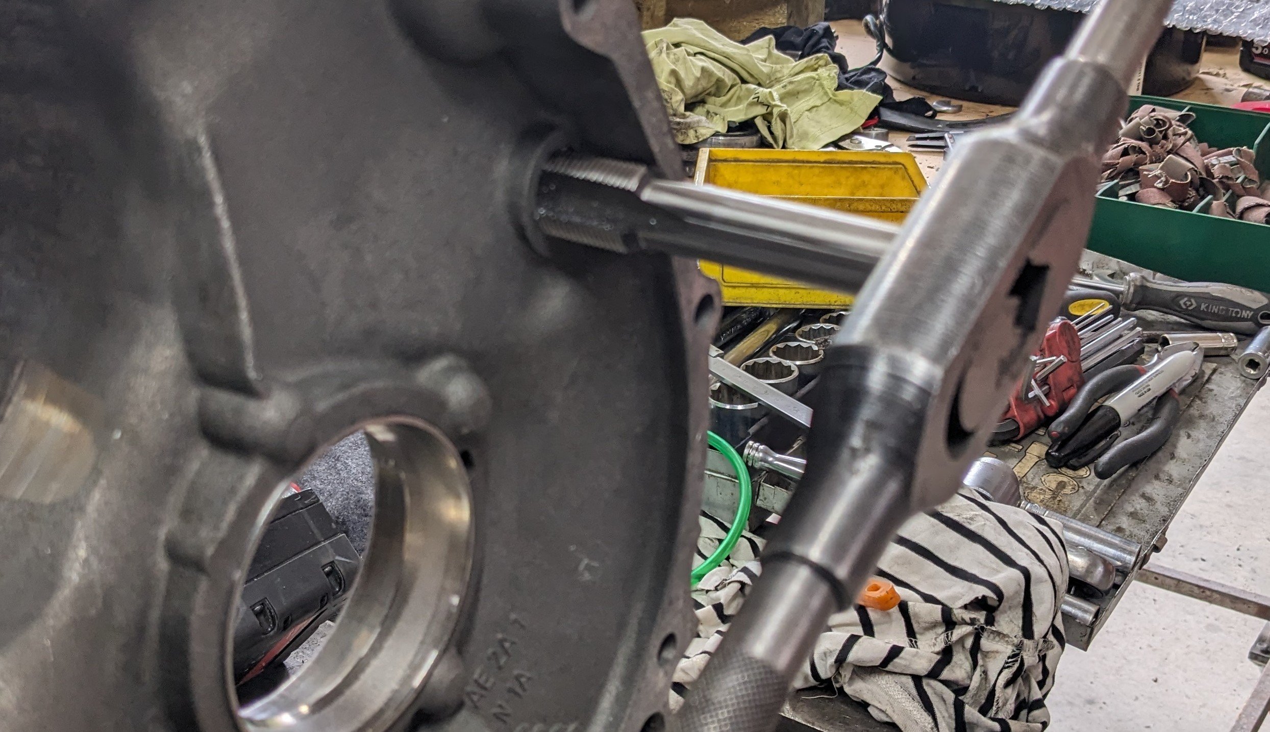
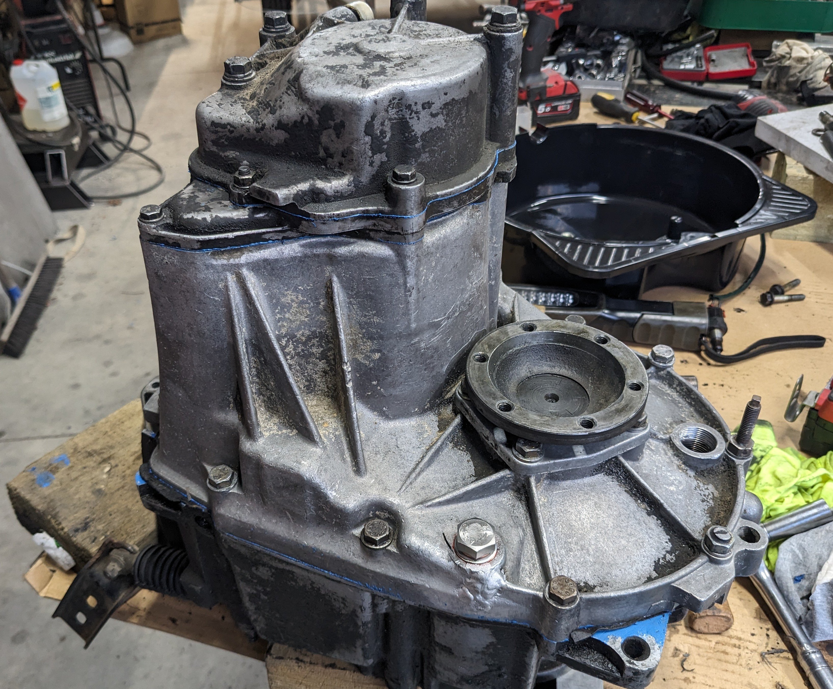
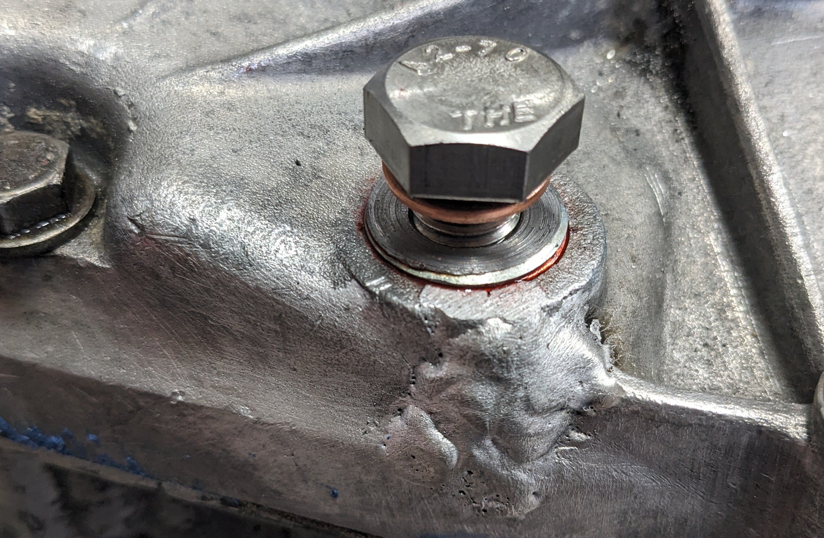
I did a thing. First I went to visit @yoeddynz who kindly welded the crack up. I also got a preview of exciting Imp developments.... When I got home I had a look to see what that plug thread was. Interestingly it appeared to be an M22x1.5 parallel thread, which meant a tapered plug made very little sense. And it just so happened that I had an M22x1.5 tap and some threaded rod. So I messed around for a while to get this; I put some pretty mega threadlocker on the insert, so it shouldn't go anywhere. Now the fucked shaft. It was pretty obvious that the broken bit wasnt a new development, and that the box had basically been working ok like that, so I did the obvious thing and just put it back together with the broken bit back in place, retained by the gear and the retaining nut. It feels fine. I figure that worst case I lose 5th at some point, by which time I will have a new box to go in. I will lift an optimistic pint to that notion tonight....
8 points
-
I ended up pulling the whole loom out to check things on the bench. It took a few hours to figure things out, I had made a few mistakes. Since I have pullup resistors on all of the cam angle sensors, the 5v supply on that loom plug splits 4 ways and joins to the signals. However I'd swapped the 5v supply wire with one of the 5v/DI signals on one half of the plug. So looking with a multimeter it still showed the correct amount of resistance on that DI, but, it was the wrong way around. Then I also found a broken wire at the plug end of one of the other DIs. Then I also found one of the pins in one of the plug halves was pushing back out when you put the plug together. So replaced the plug. I've got all of them responding on/off when holding steel against the sensors. While I was there I also changed the supply to 8v instead, hopefully less chance of trigger errors. Hopefully it'll all work okay now.6 points
-
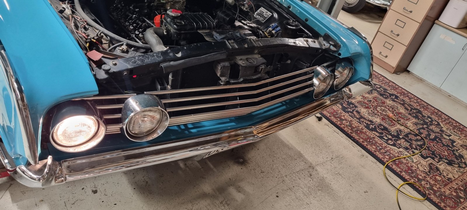
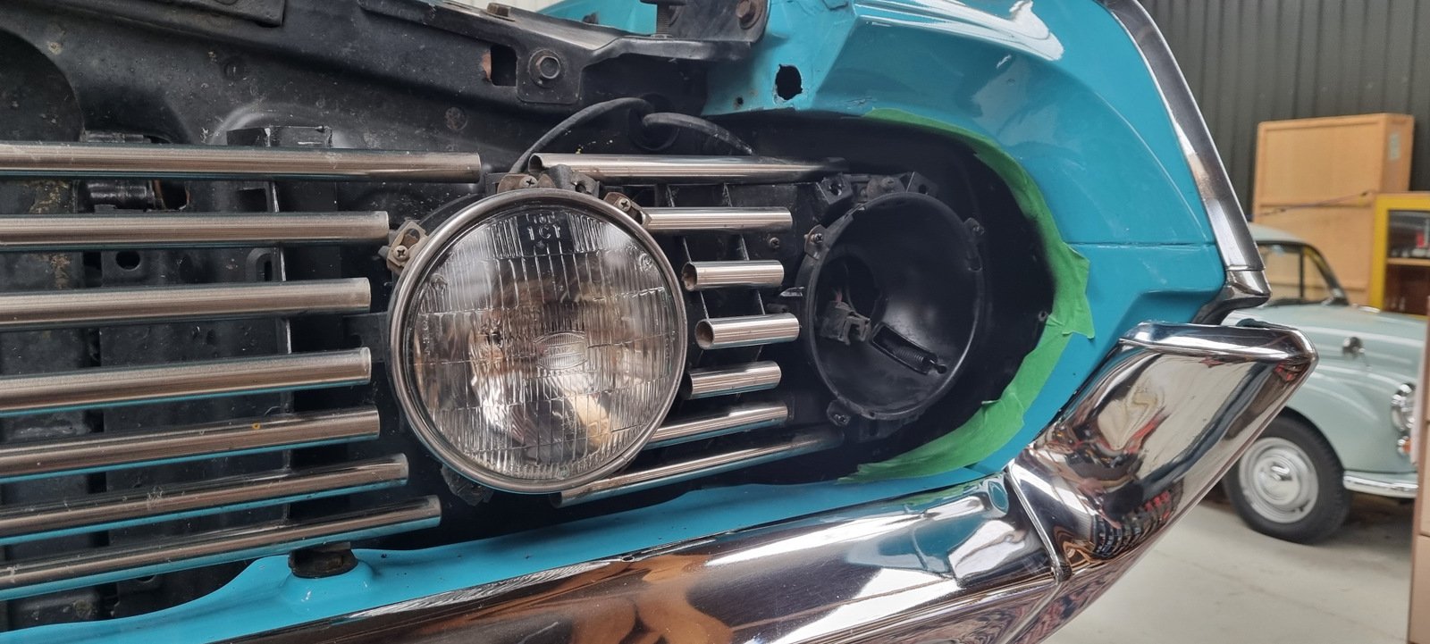
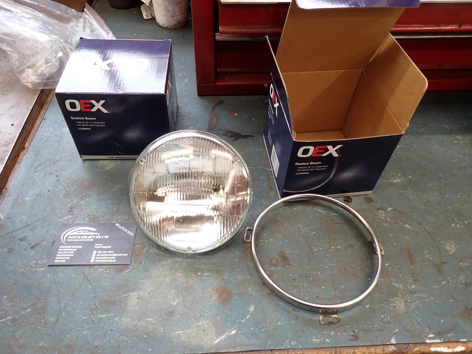
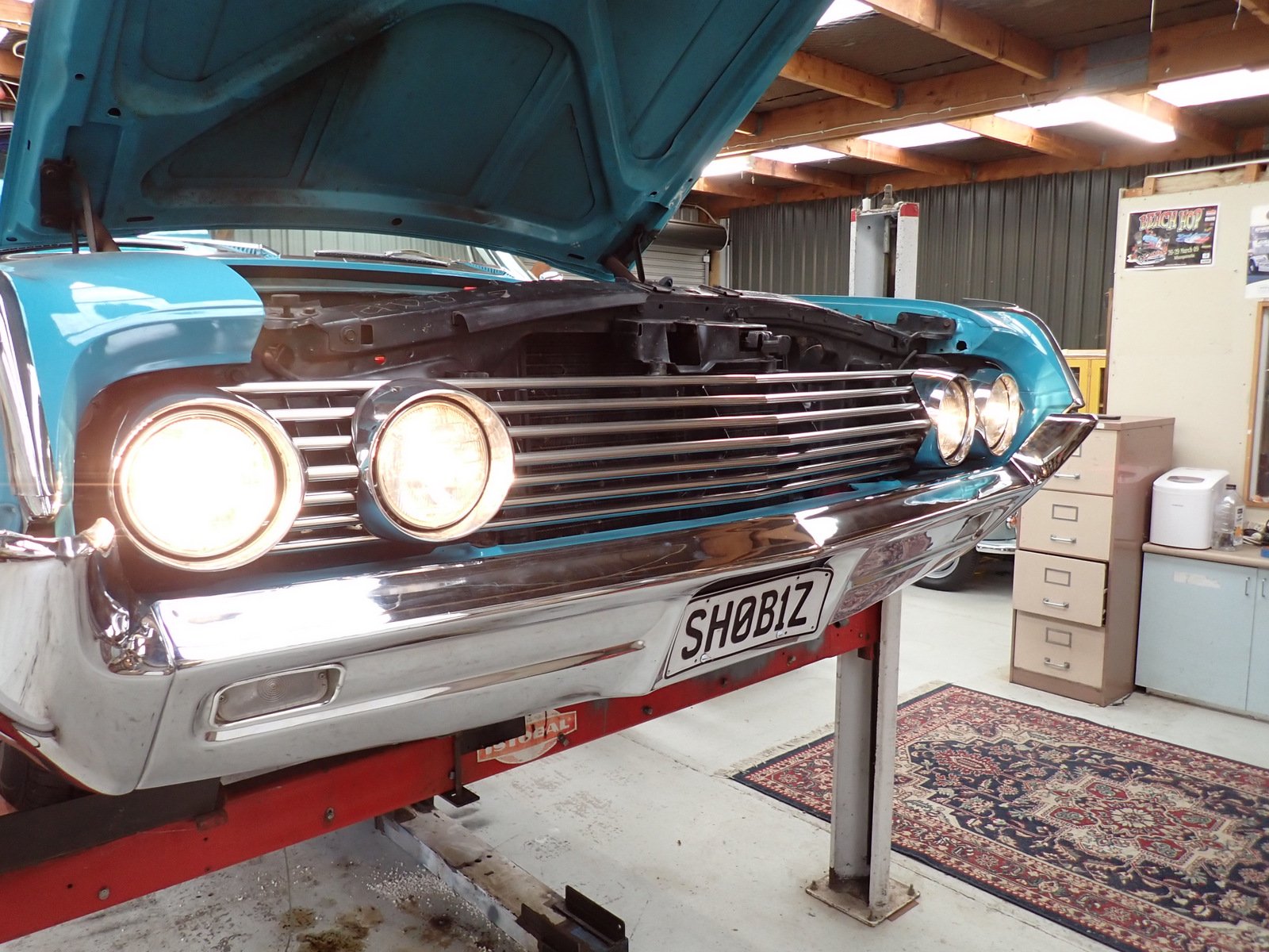
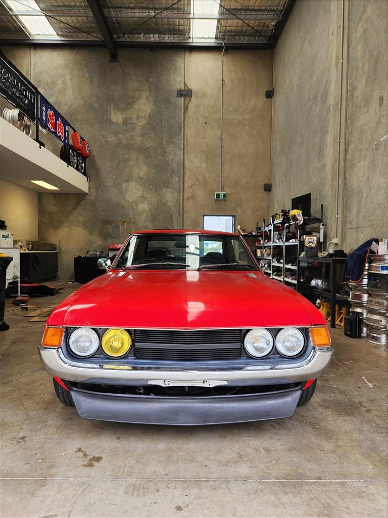
One outer headlight (dip/high beam) gave up the ghost during Beach Hop. I installed these when the car came to NZ in 2003, so last 21 years, fair I suppose. The working one looked a bit sad too so I though I'd replace both. The centre high beam set are the ones it had in Indiana and seem fine. Took them out and cleaned up the buckets (I ended up doing all 4) followed by a squirt of Black Zinc. I did the same for the small aluminium trim pieces that go in where the masking tape is, and the blacked-out areas behind the grille that were a bit scruffy. It turns out that modern Hella lights (stocked at BNT) are all semi-sealed and don't have the nice domed shape so I got a couple of 5 3/4 sealed peams from PartsSelect on TM Let there be light! Also picked up some used PP from Trademe.
5 points
-
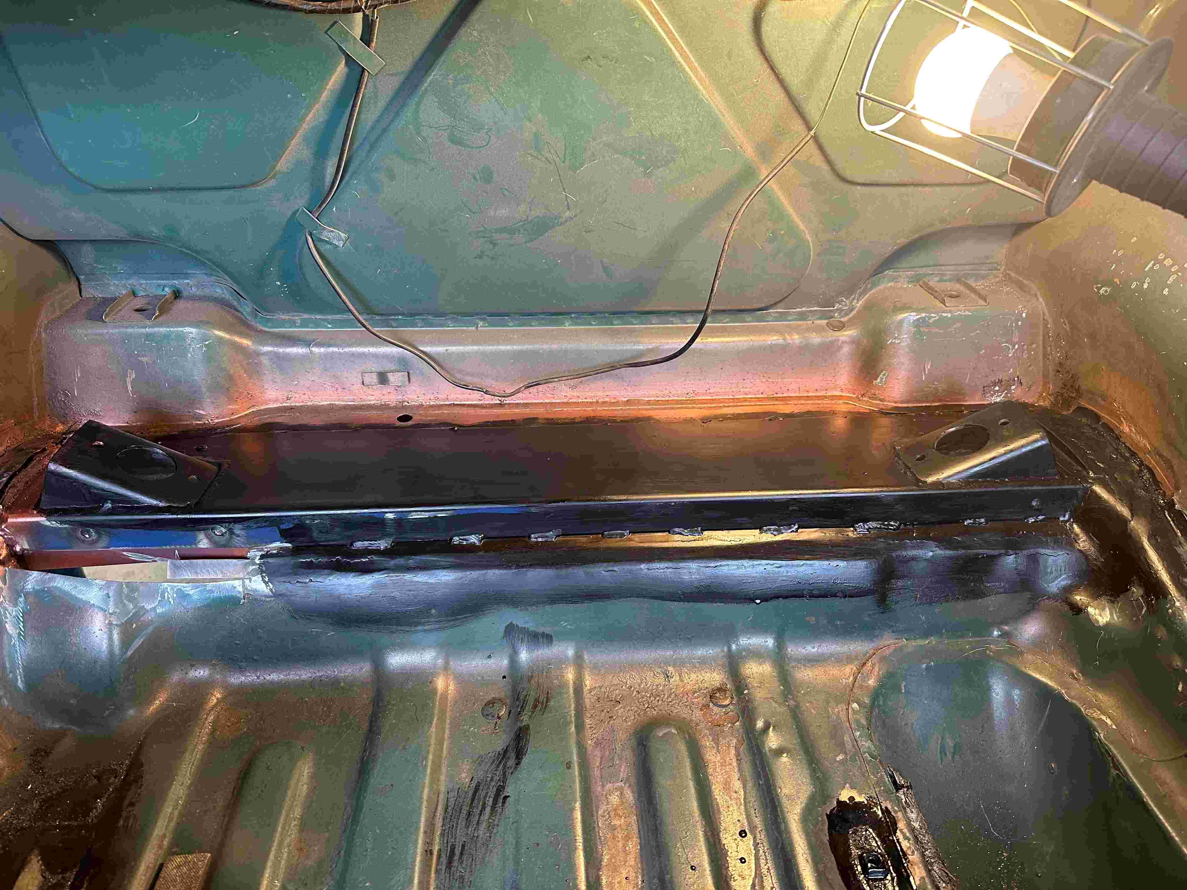
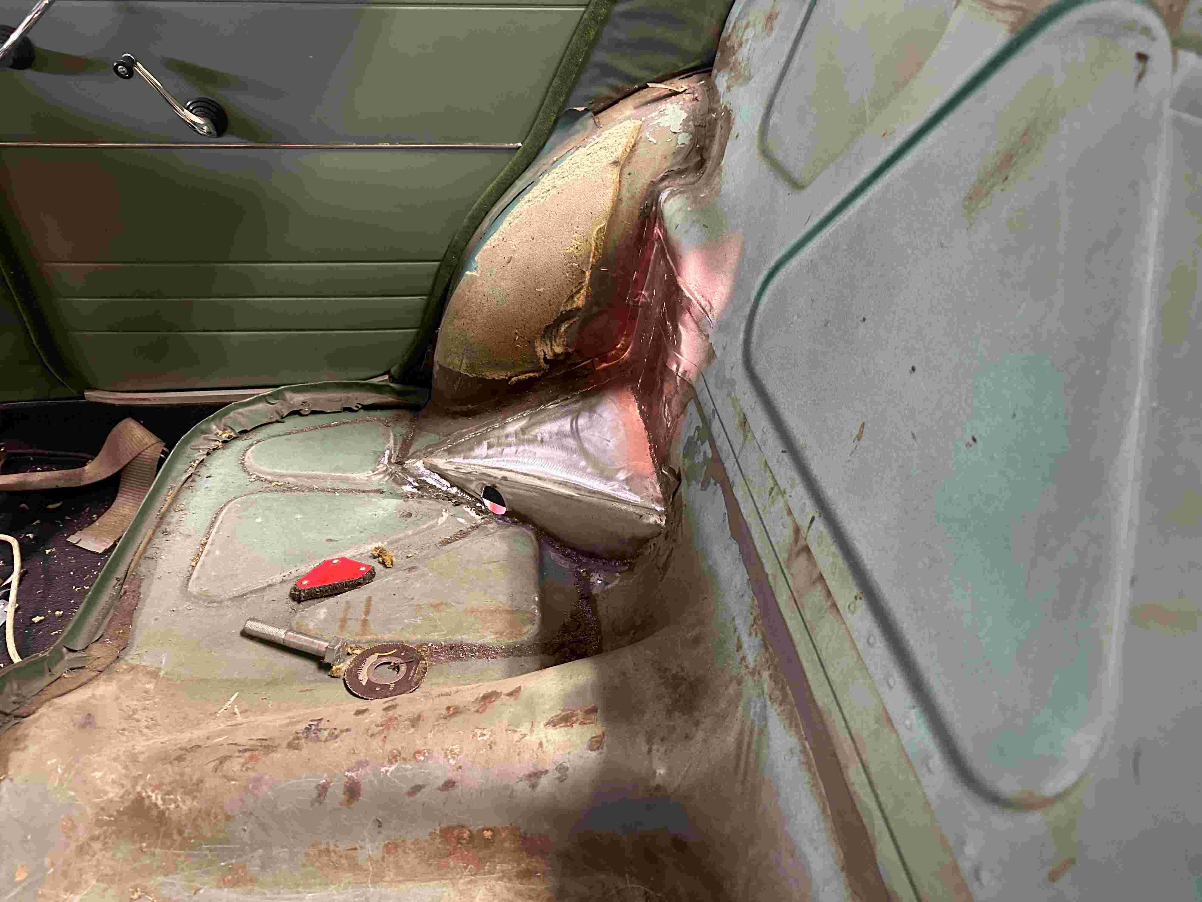
A bit more progress with a fillet piece welded in and the sheet metal replaced covering over the fish plates etc. I have also replaced the section I had to remove in the rear seat for the top trailing arm on the drivers side.
5 points
-
I've got extra outputs on the megasquirt. I could set up a stepper motor to open them at set values. But realistically I'd probably just be opening them at certain times for lol effect. Like outside an oldfolks home at 3am or next to a community hall where there's a workshop for those who suffer from ptsd. Joke. I would not do that.4 points
-
Bicycle sprocket m8 Our stove top actually came with a cast iron one stock,but nowhere else I have ever taken my coffee pot has ever had one
3 points
-
A+ job bro. Nice trailer to tow and reverse etc, one careful lady owner. Suits small cars, but allergic to FIATs. No regerts, would FIAT with this trailer again. GLWS3 points
-
I use this stuff now. is a whole lot cheaper than buying from motorbike shop etc.. https://nzfg.co.nz/product/muffler-packing/ sometimes use a bit of chop as well3 points
-
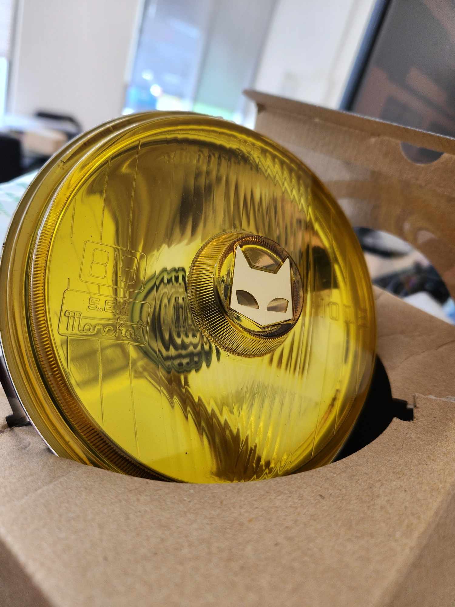
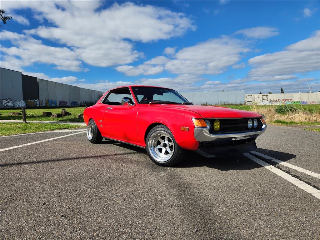
Not too much done today, but I did get a replacement headlight for the one I broke ages ago when I was fitting the others. It was not actually intentionally meant to be a blank space. SEV Marchal! I always liked the look of yellow and of course the sweet cat logo. I will just run one, a little bit of style perhaps. Plugged it in and it works fine so that was easy. Although I need to figure out why the passenger outer light turns off when the high beams are on. Not super high on my list of priorities seeing as it's unlikely to ever be used anyway. I finished putting undercoat on the driver side so installed the side metal trims just using some screws. Not the best but it's what I could find that fits. Gotta fuck with the dick you got. Not sure they will stay in there securely so I'll have to keep an eye on it. When I was out taking these photos just down the road some guy gave us a toot and a thumbs up on the way past and I was only out there for about 2 mins! Unfortunately (but probably not unexpected) my front demister blower isn't working. I can't remember if it ever worked but I might look at trying to get that going again as it could come in handy. The rear demister I'm fairly sure is totally cooked but that's not such an issue as the front.
3 points
-
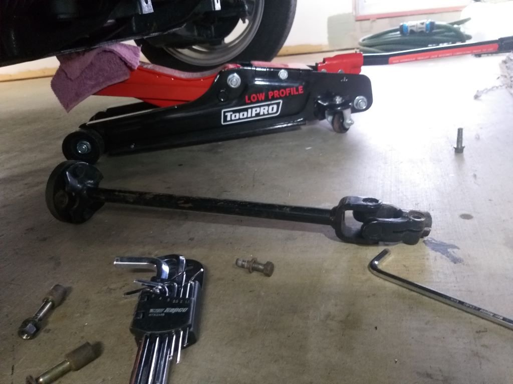
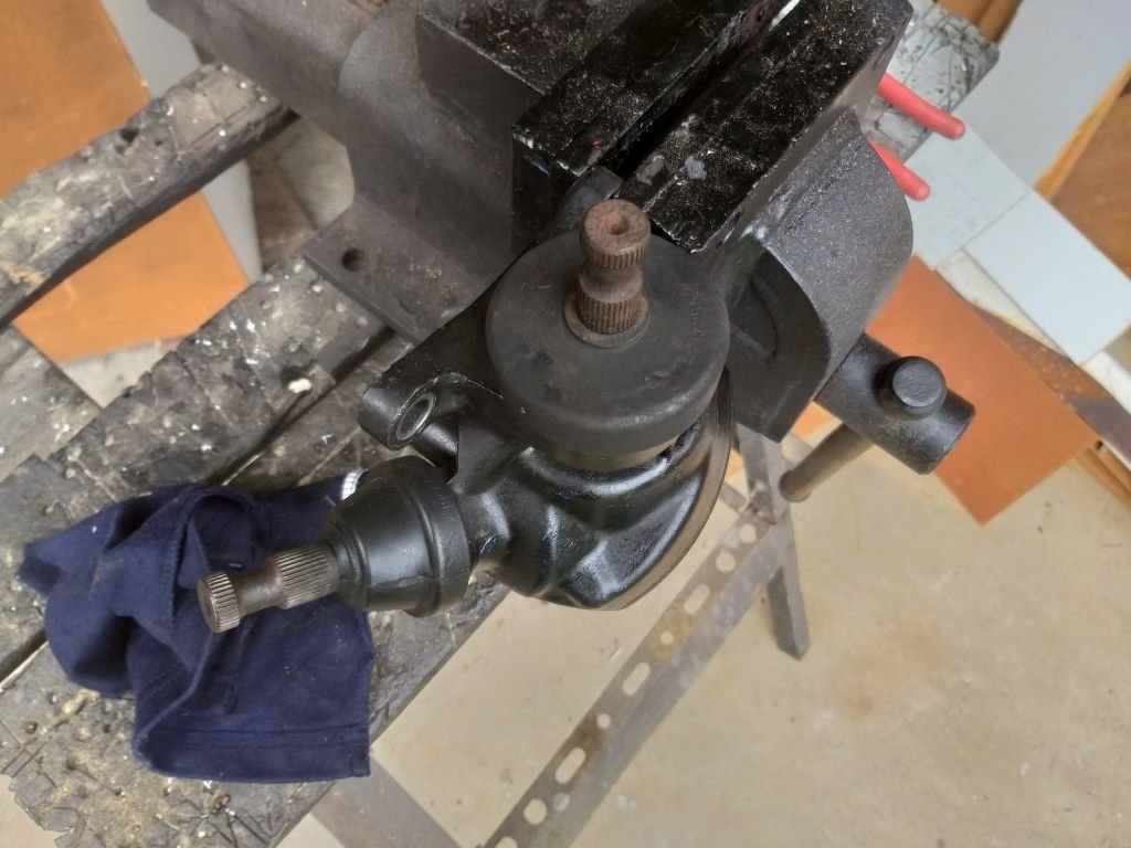
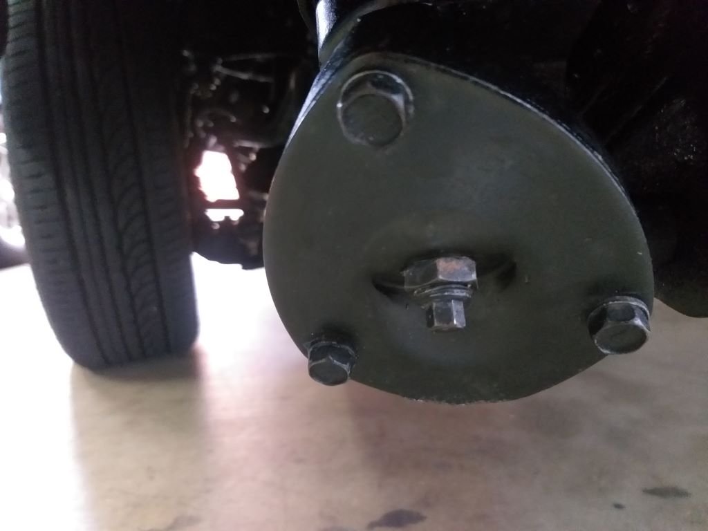
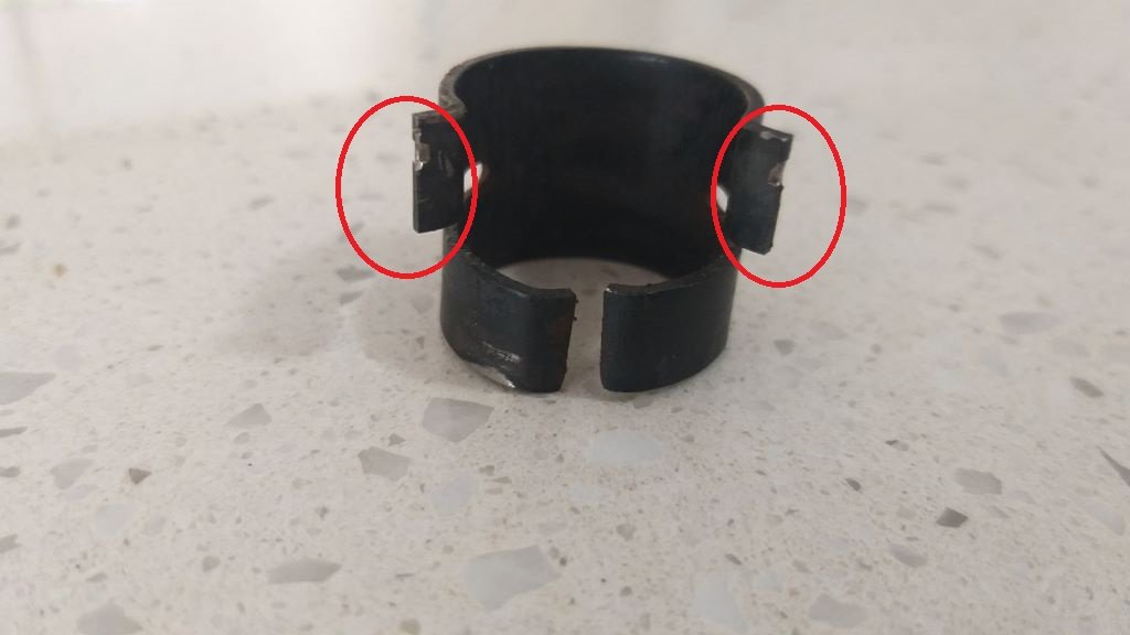
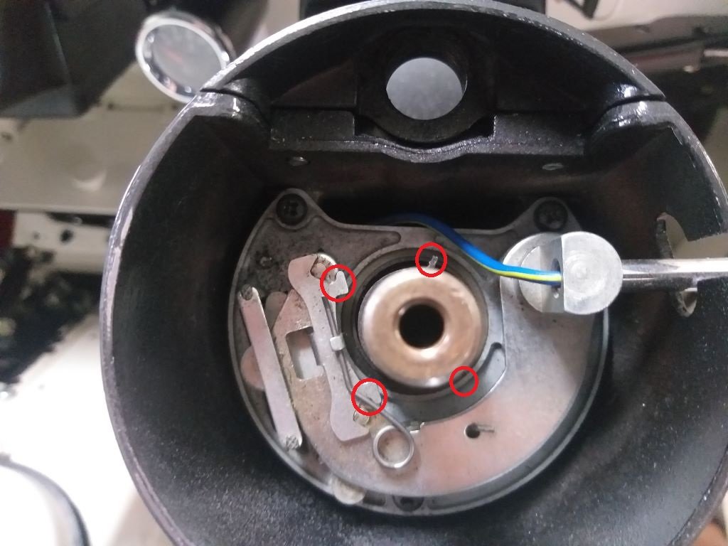
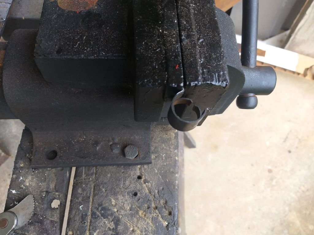
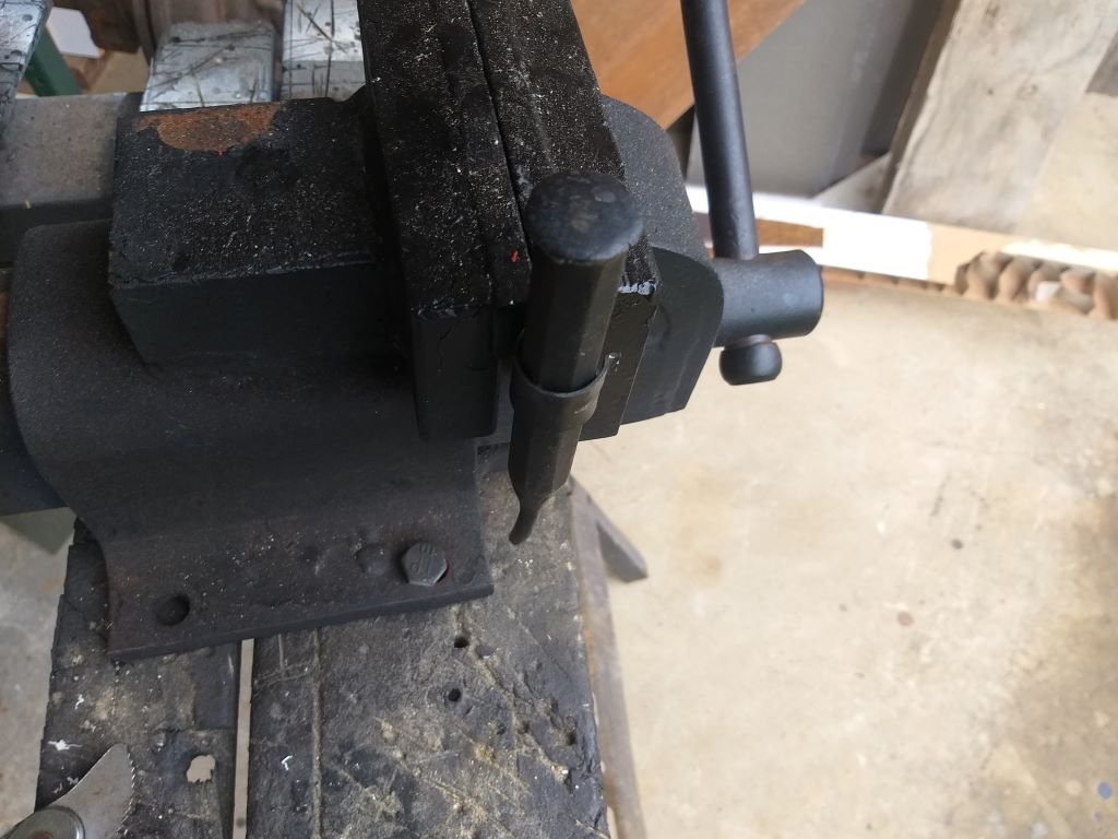
Over the last few weeks, I've noticed a steadily increasing stiffer steering and during last night's burger cruise it felt particularly bad. Figured I'd do a bit of fault finding today. First step was to remove the intermediate steering shaft to determine whether the issue was on the steering rack end or the column end. With the intermediate shaft out I fired up the engine and waited the few seconds for the Astra pump to come online. What a relief it was to find out that the issue is not on the rack/pump side of things. So turned my attention to the angled steering gearbox and the steering shaft itself. Pulled out the angled gearbox for a closer look. Popped the cover off to check the lubricant level. Turns out it uses grease - or at least mine is filled with grease. I'm hoping that is factory and not some previous owner's bodge job. Anyone know ? Anyway, I neglected to take a photo, but it looked like some of the grease had shifted leaving the top half of one of the gears dry. The grease looked to be clean and still in good condition, so I just topped up the level and fitted the cover plate back on. At the same time I spent a bit of time fine tuning the little adjusting thingy till I got the mechanism turning smoothly: While I had the angle box out, I pulled off the steering wheel and dropped the shaft so that I could grease the upper and lower bushes. They were pretty dry. With the steering wheel off I figured I'd tackle another annoying little issue. For a good while the indicator self cancelling feature on left turns hasn't been working. Works perfect on right turns though. Really aggravating as I keep forgetting to manually cancel the flashers and also pretty unsafe. Anyhoo, I took a closer look at the mechanism and it was visibly okay. There are two little "ears" on a spring steel collar that press fits over the inner steering shaft. Looks like so: Each little "ear" engages with a double ended lever attached to the indicator mechanism. One of the "ears" isn't visible due to the angle of my photo, but I've marked up where it is supposed to be. With a visible inspection not showing anything untoward I enlisted Mr's Flash's help to watch what was going on while I turned the steering shaft from below. Turns out the little "ear" on left turns was not triggering the self-cancelling lever. Pulled it out the collar for a closer look. Both "ears" are showing signs of wear with noticeably more wear on the left one. Thought I'd try and give it a tweak, so clamped the offending "ear" in my vice: Chucked an appropriately sized punch down the centre of the collar to maintain its shape: Then gave it a little bit of loving with a hammer. Popped it back on the column for another test and ... success! With the self-cancelling issue sorted I reassembled the steering and dropped the van back on its front wheels for a quick steering test. Nice and light once again. Loaded up my ratchet with the appropriately sized socket and headed out for a road test and also to re-centralise the steering wheel. It took a few goes until I got the steering wheel perfect, but I'm happy that things are now back to normal. Thanks for looking.
3 points
-
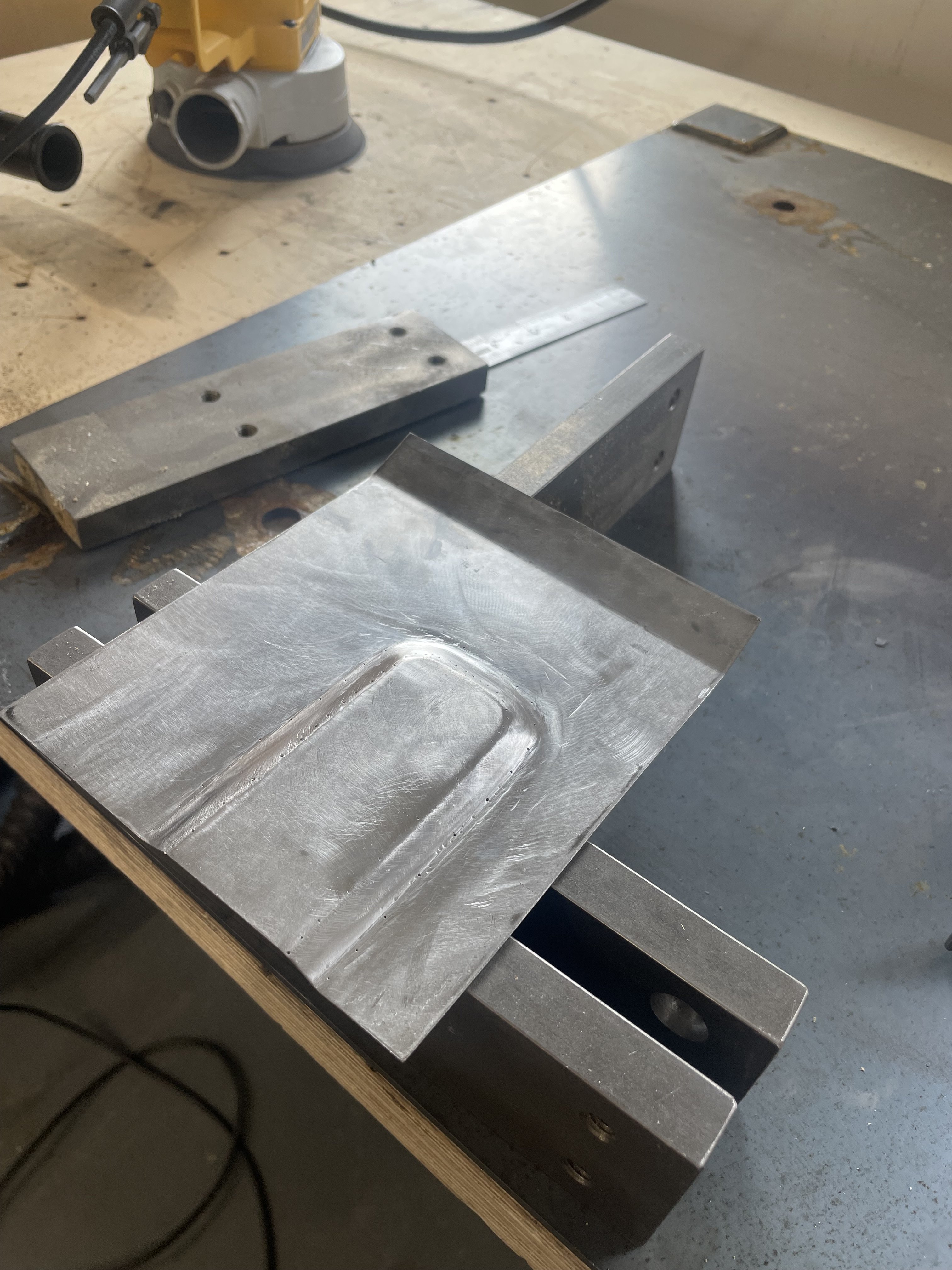
Well after the last novel length wall of text I'll try to keep this update shorter otherwise I'll never finish the thing. Lots of little jobs starting to pop up on my 'to do' list. Driveshafts. Connecting the scooby shafts to the imp axles. A job I wasn't sure which direction I'd take as there's so many different ideas out there on the nerdnet showing 'the best' way to join shafts. First thing I did was to double check the suspension travel allowed by the stock shock absorbers and then use those datum points to work out if there was any growth in the length of shaft required as the wheel moves through it path up and down. There was minimal amount, like maybe 5mm at the very most. I guessed as much because the stock Imp driveshaft doughnuts dont allow for much sideways travel. I then cut one of my 22mm scooby shafts down in length so I could work out the lengths required with the CV joint in place. This move I soon regretted. I was allowing for plenty of plunge into the CV joints to make sure the whole joint could be removed from the box stub axle with the box pushed sideways when removing the transmission. I was happy with the length and then decided to go visit a local hotrod builder friend for some advise. He's well known about for his many many full scratch builds and has done heaps of driveshafts in his time (a fellow machinist by trade too) I showed him the two ways I was considering doing the join. He showed me a better way. Shrink some bored out yokes cut off from some spare axles. Plenty of meat, will never let go and even if they somehow did loosen and spin they cant come out because there's not enough travel in the CV joint to allow them to. No welding needed. He's run axles done in the same way with some serious big block power and they never let go. Just has to be accurate and luckily its the sort of machining/fitting job I like. But i needed to start with almost full length scooby shafts to do it, of which I was now down on.. Roll eyes and back to the wreckers to see this beauty get pulled from the hedge... Hannah helped me remove the shafts. It was her birthday too so wow, what a treat. She got visit the wreckers and get oily. Got home and the shafts didn't fit my CVs. Bigger diameter end. Really weird because I checked online... ha. It lies. Turns out some late 4wd Leones had even bigger axle ends than the imprezzas. Also odd is that one shaft is 22mm and the other side 24mm, although both the same length. Back to the wreckers. This time I got larger 25mm shafts with the smaller ends from front wheel drive Imprezzas. I grabbed two pairs. Same again, 22mm on one side and 25 on the other. Now I had two of each. Got home and spent some time cleaning them up, outside because petrol fumes. Cleaned up the spare pair of axles in the lathe to make sure I had an accurate clamping spot for the later boring. Good quality steel! I turned them down to less than the 23mm bore size and chopped the yokes off. Made lots of swarf Bored out to bang on 23mm with nice radius. Double checked and triple checked I had my lengths required correct. Chopped the two 25mm scooby shafts down to length and turned a step down on one end of each, a radiused step to stop any stress risers. I went for .0015"~.002" interference. Go online and see the debates between all the barries about what a good shrink fit should be There's many variables as well. I consulted my old faithful machinery's handbook. I wanted it tight, but not stressed. Luckily the axle is of good steel. I also made a sample first, using one of the cut off bits of scooby shaft and some 4340 I machined to the same outer dimensions as the yoke. This way I was able to test how hot I needed to get it to expand enough to drop in place. I'll take this to a local engineers who have a press with a pressure gauge and see how much force it takes to wreck this thing Here's about a one hundredth of a millimetre (iirc) getting removed.. Then things got hot.. photos taken after it was done because I had to move bloody quick! Hannah would grab the torch and I would drop the yoke in place. It was a tense bit of time. If the yokes teetered and grab they'd pull the heat so quick and shrink in place before getting to the shoulder. No removing them without damage and I only had the one pair of spare axles. It went well. I was happy and relieved. The light rust flashing off on one is simply due to that one having been left nearer the front of the workshop to cool down and it was a chilly damp start to the morning. They wired brushed up neat as, got painted with black epoxy and when that was set they had new universal joints fitted. I cant try them on the car until I remove the existing axles from the hubs but it should be fine. Next up was to sort the fuel tank out to suit fuel injection. I brought the blue imp in and checked a few ideas out on what I could do. I don't really have room for a surge tank and I never liked the noise on my Viva from the external fuel pump anyway. Nor did I like the way the fuel in the surge tank heats up. Enter the humble Nissan Micra k11 intank fuel pump and surge container... It actually looked like it was just going to fit into the pressed depression at the bottom of the imp fuel tank.. With enough room to run the imp fuel float sender next to it. Cut a hole.. It fits. I'll cut the bracket off the side at bottom of pic and it'll move sideways a bit more.. Made some metal brackets Welded them in and now I have a cradle that takes two cable ties across the top to secure. I needed a flange.... Made this. Its designed to recess the lid about 10mm below the tank top. I want to keep the tank top as flat as possible. It'll have the usual layer of foam over top but I don't want things sticking up proud when the 'frunk' is being used (cant be tearing those bags of concrete now eh....) Many holes drilled and tapped.. Carefully welded in place. Was a tricky job. Thin steel on the tank that had some sort of (probably poisonous) coating. But happy with result. I made another hole... That takes the sender. Drilled and tapped more holes to suit. Now I needed to get fuel from the outside in and from the inside out. I machined up these in stainless.. Thought of a neat way to hold the little bits together for tacking. Blue tack. Or blue tack tack? welded up.. I made an angled recess into the hatch cover so the fuel hose goes even further below the tank line. Visible in that photo are the cable connections. Again - I needed to get power in. I machined some shouldered fittings in plastic.. Luckily the micra pump so handily just uses a simple connector with 6.3 spade terminals. Under the lid... Tank hard work done. I'll paint bits and cut some gaskets. Speaking of gaskets. One of mine between my oil filter pedestal and the block is weeping oil. Plus one of the bolt heads weeps. Typical. Put a Japanese engine in a British car and turn your back for a minute... I've already drained the oil cleaned it up and ran a smear of paintable sikaflex along it and around the bolt head. I didn't take photos because not really exciting. I'll paint it silver and no one will know. Except you the reader. Next up is the exhaust I think.3 points
-
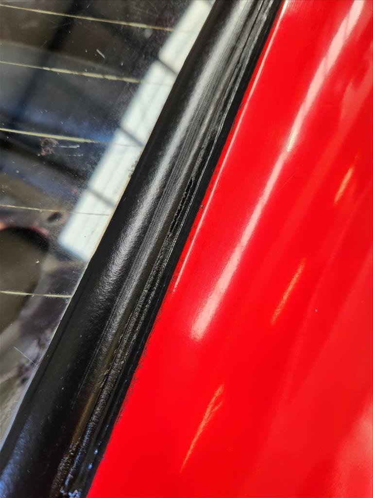
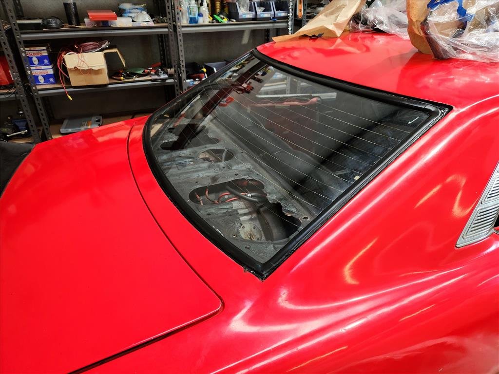
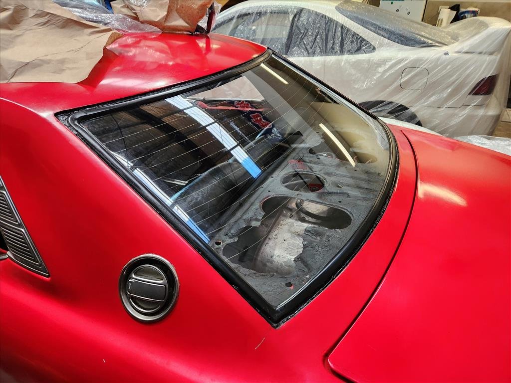
OK last post about painting trims. This time I did the rear but it didn't turn out as good as the front I don't think. I had to get some new tape and I think this tape is probably shit (it is because I got the cheapest one) and it let a bit of the paint bleed through the edges. I tried to rub some of it off with isopropyl and solvents but it ended up just rubbing the paint off as well. Same problem with using a blade, the paint is so bad the blade just sliced it. Then I thought about it and figured it was dumb to stress about these little bits when you look at how the rest of the car looks anyway haha. 10 footer with an instagram filter all day.
2 points
-
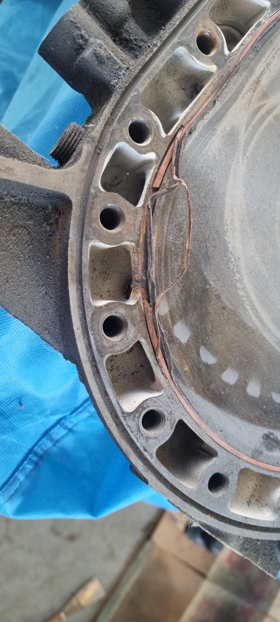
My irons were mint with no corrosion at all but the metal between the water jackets and the seals is pretty small. Apparently it’s pretty common for it to break.
2 points
-
Smoke the hemp first, then scrape the shellac out of thr bong2 points
-
Chop strand is unpleasant to use. The bike/kart repacking mat is much nicer.2 points
-
Good recovery on both the problems. For some reason the X1/9's seem to have 2 or 3 jesus nuts. which if they come loose do serious damage. That shaft damage was most likely caused by the nut loosening. I found on ours the guy who fixed a rear suspension balljoint hadn't adequately tightened the nut on the end of the axle/hub carrier. Discovered it on a test drive and limped it back before anything major fell off. Wheel could go in and out 2 inches when i got back. Good design doesn't leave things up to how tight a nut is done up.2 points
-
yeah i figured its a club liability caveat i just thought it would be funny to call the friendliest group of people i know fascists. Foaming for this event though. Have made a plan to deliver my Suzuki Swift GTI to my bush block so i can bring that instead of the boring CRV2 points
-
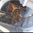
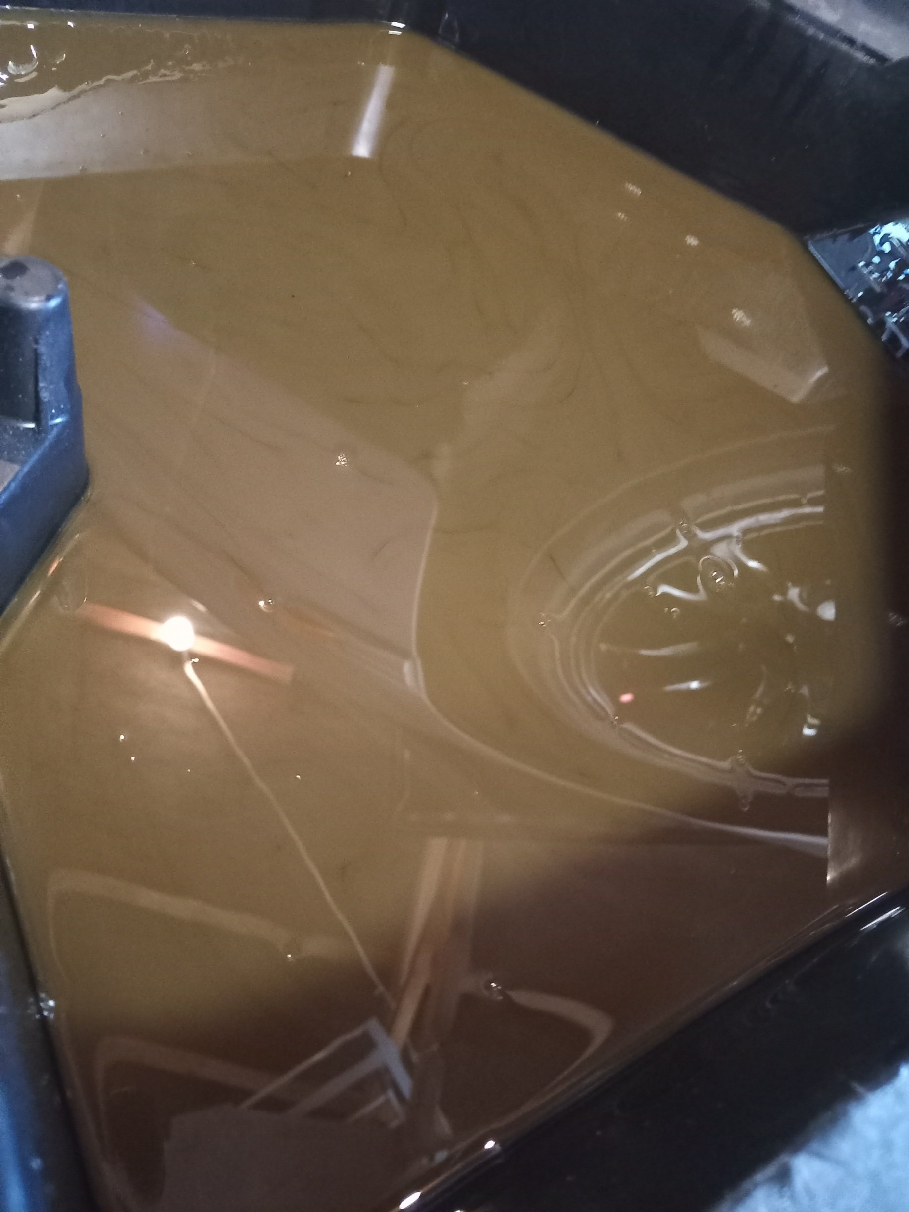
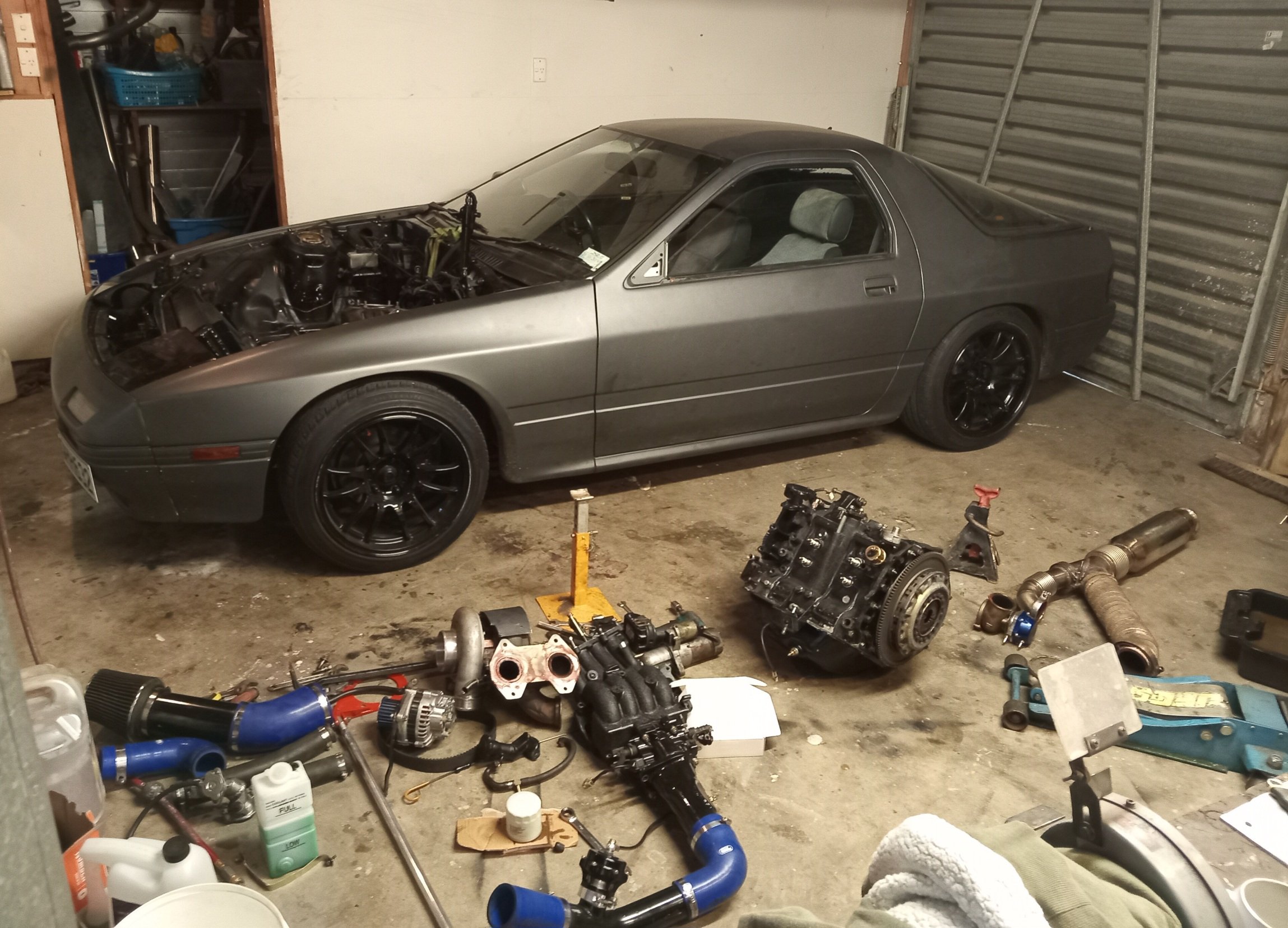
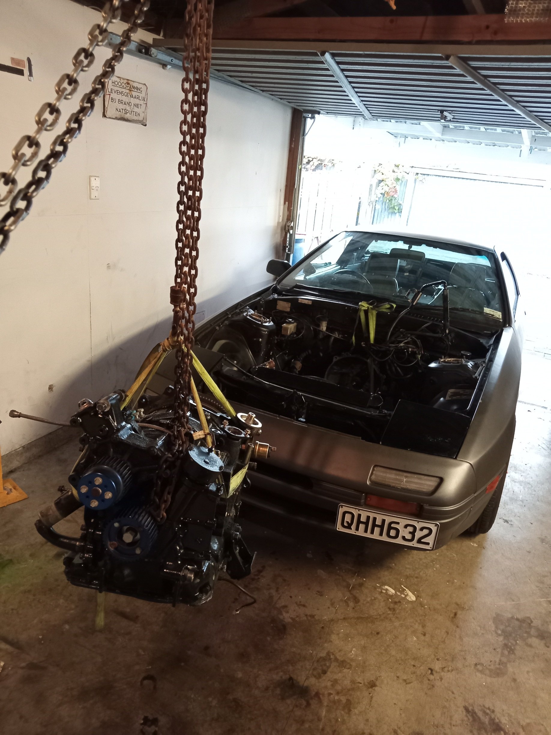
Well this ran with a misfire upon entering boost since i got it, now its really started being undriveable, i checked tps, coils, all the things that could cause that miss and came up with nothing definitive, it always smoked a bit but i thought this was as a result of being rotary and then i noticed the oil looked cloudy on the dipstick, changed it for fresh oil and filter.. The oil looked like this after 10min run time and smells kinda like coolant, time to rebuild, im guessing a water seal let go or something... I should be sad about this or something but im actually looking forward how a rotary engine looks inside, especially a 'worked' one.
2 points
-
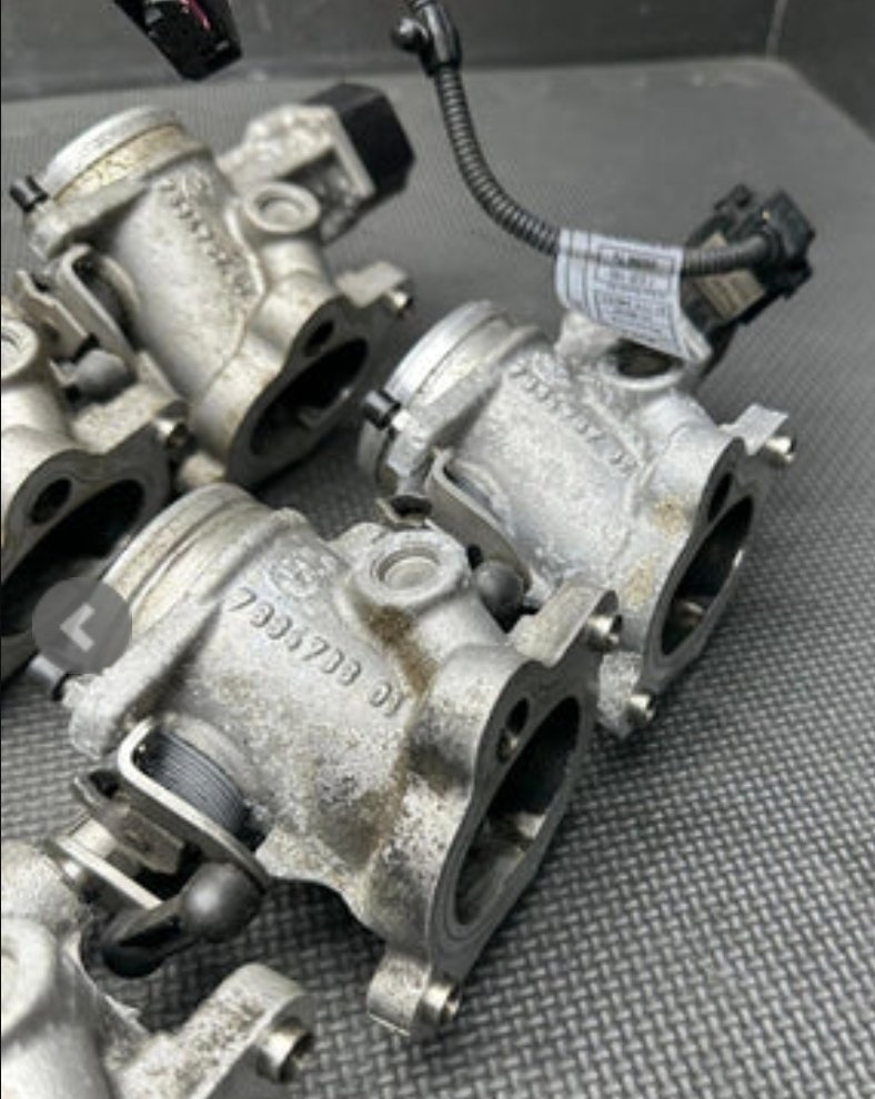
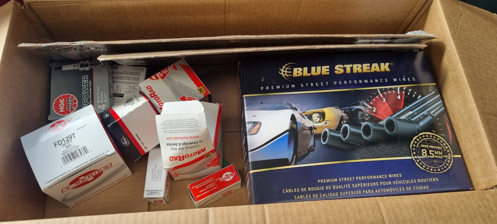
*girly screams of excitement * just got these through
2 points
-
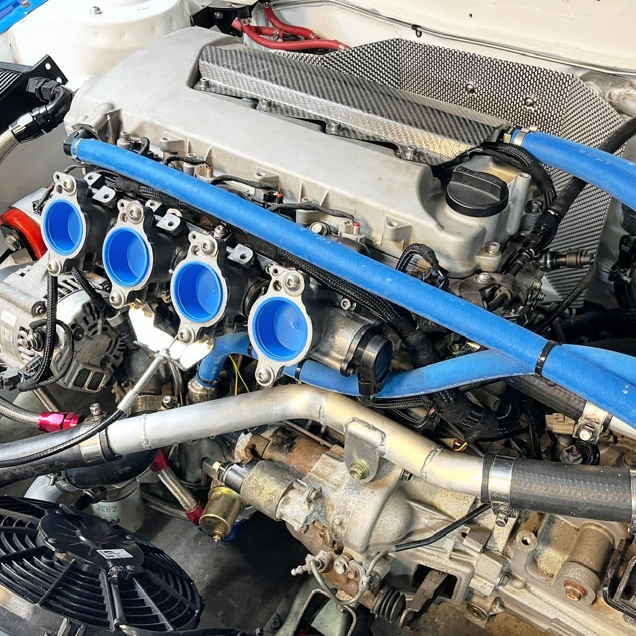
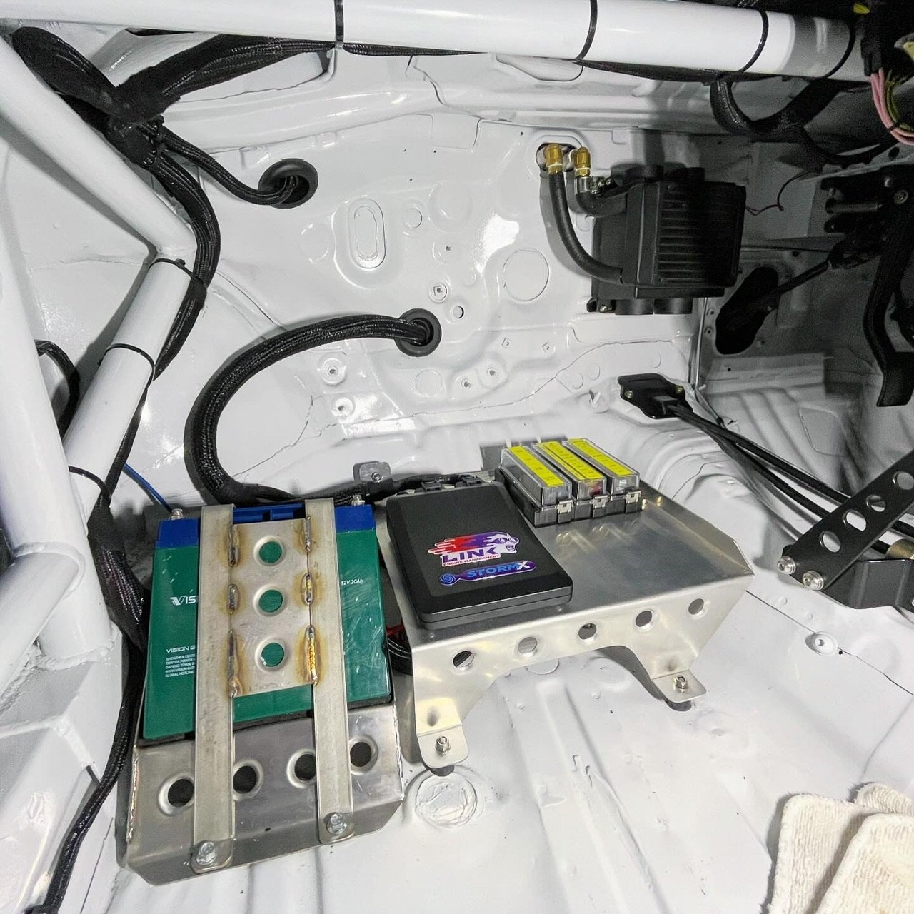
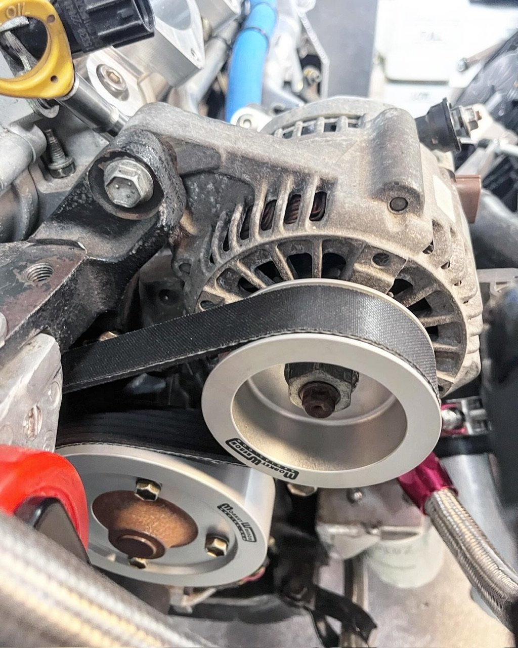
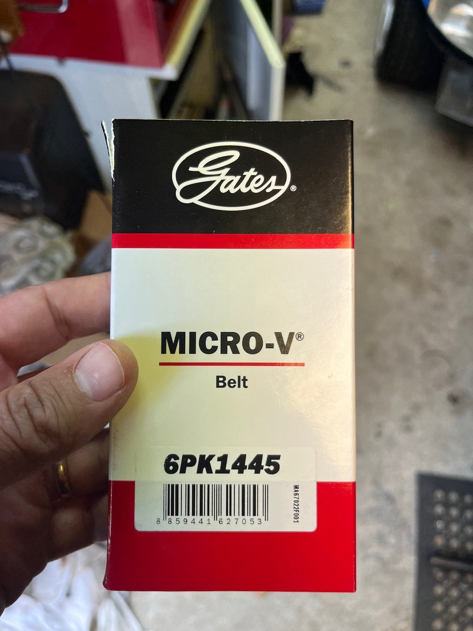
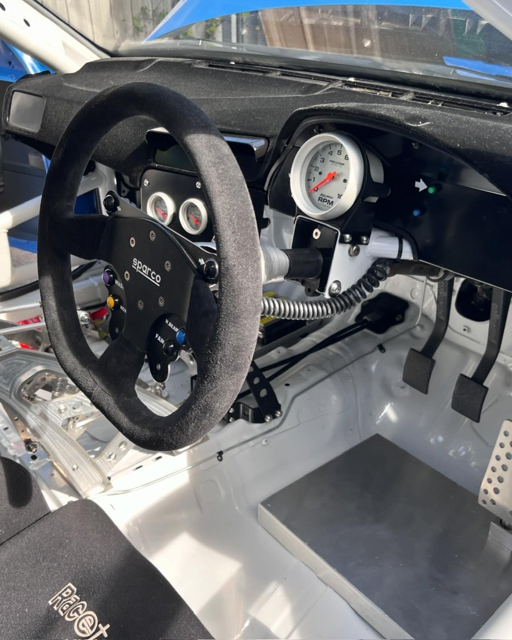
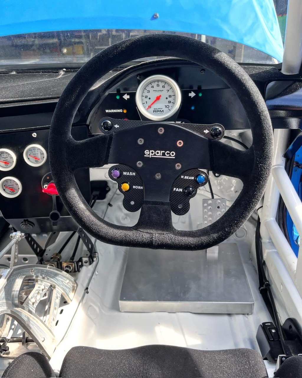
Quick update. Been busy over the past month so this has taken a bit of a backseat. Got some stickers made for steering wheel/dash. Makes it feel a lot more finished. I’m not 100% happy with them yet but they’ll do for now also tidied up the curly cord mounting. Looks legit now. So the set of pulleys I brought back from the states didn’t fit my alternator (which turns out is from a 1zz fielder). So jeffy came to the rescue and made a bush to suit. For future reference..1445mm belt works with no PS, and underdrive alternator and water pump pulleys. This took quite some time to figure out found a wee molded hose to finish up the heater piping. Still need to 3d print an airflow thing for the dash heater ducts. Cooling system is now sealed and ready for a pressure test (pending a few extra hose clamps!) Also replaced gearbox axle seals and filled with oil for first time in 10yrs. Hope not too much damage has been done from sitting around. Bought and sold another Levin to pay for Link Storm g4x and engine wiring loom. Loom worked out great looks very hidden away. Some small mods to make but all simple enough. next up; 1. fix stripped thread in engine mount 2. replace sump with baffled version 3. remount expansion chamber 4. make headers 5. first start??
2 points
-
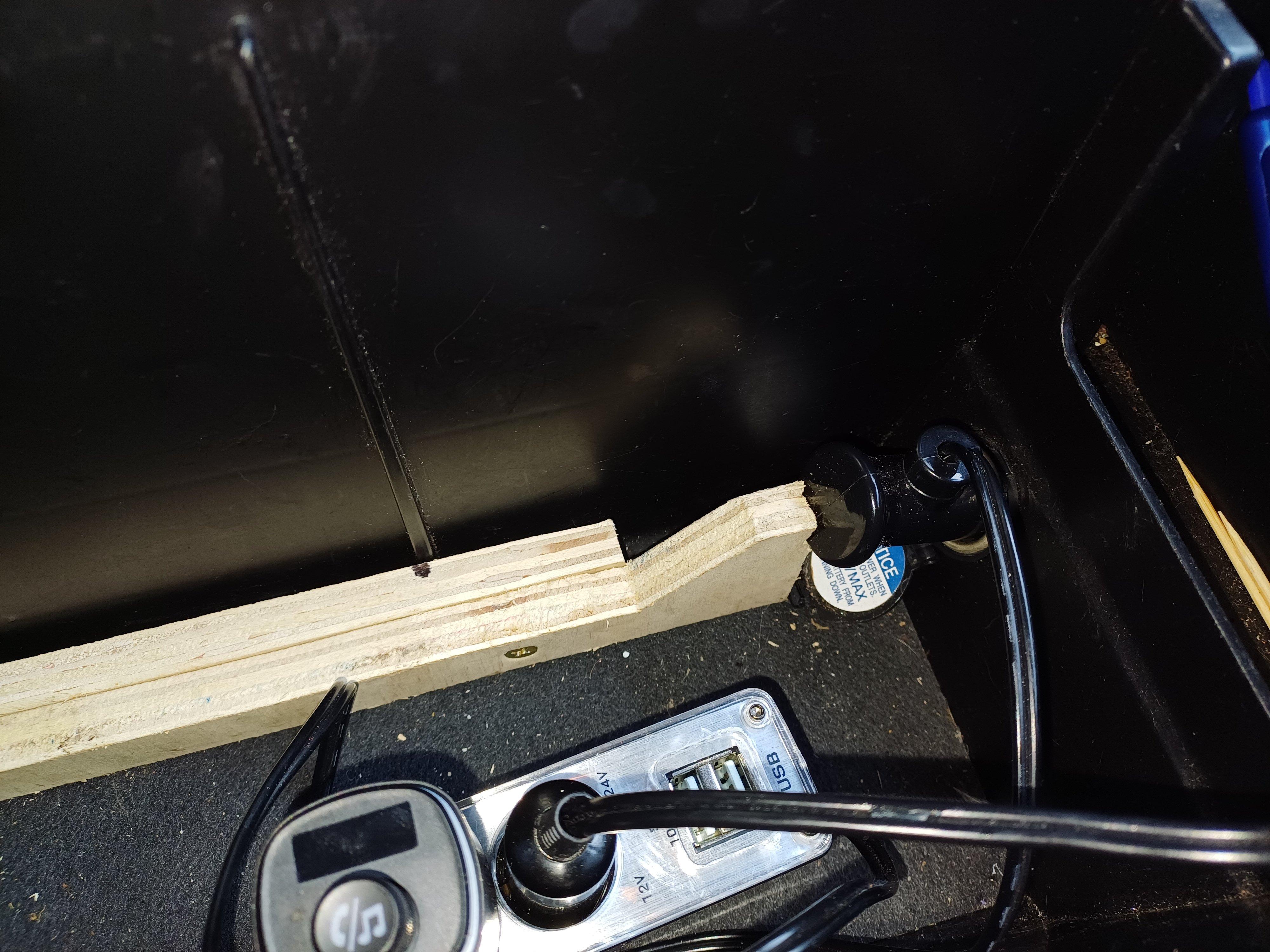
Middy's phone has a soggy battery, and she's complained it doesn't always charge in the car. The cig plug was coming out of the socket, so Now I can go back to ignoring the phone battery
2 points
-
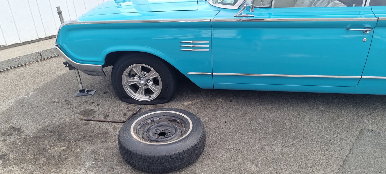
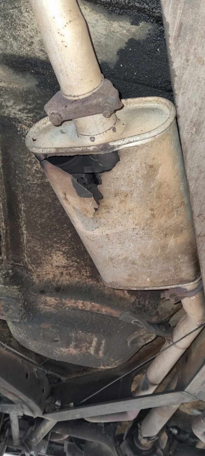
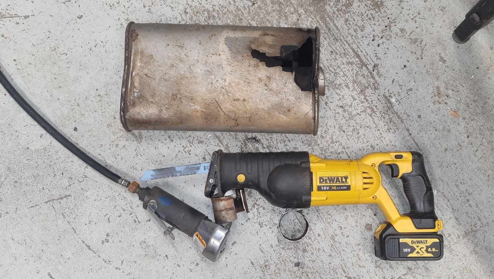
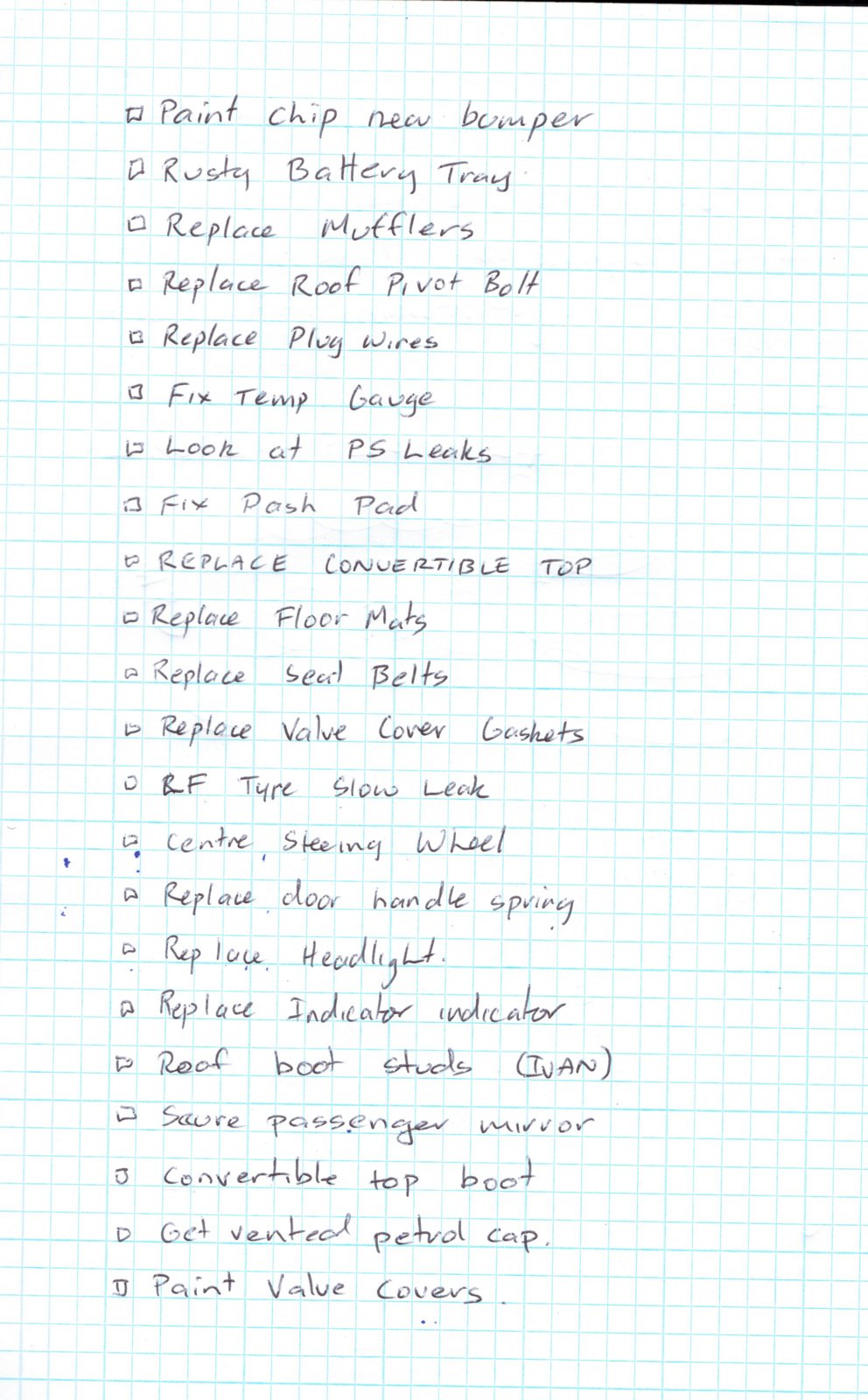
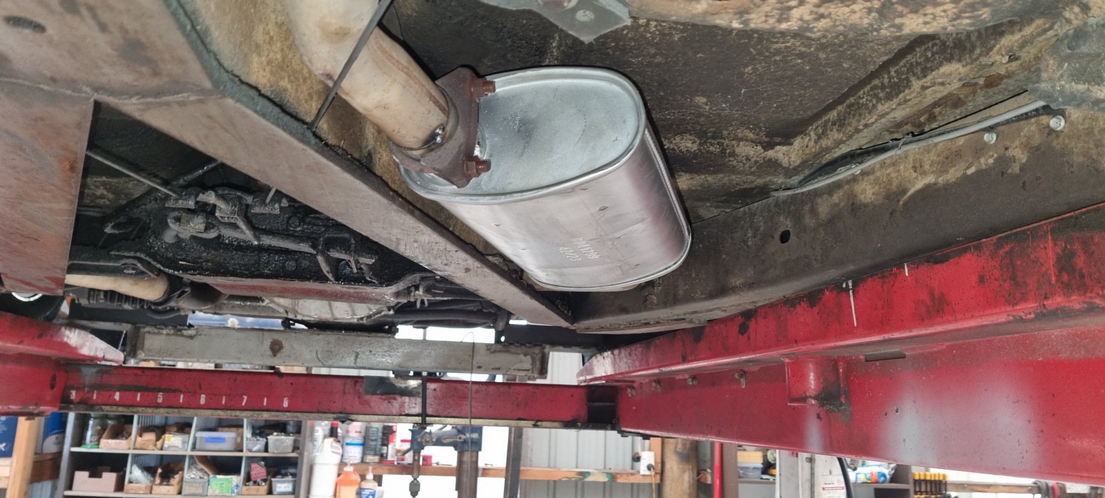
On the way back the LF tyre was going flat fairly quickly, and needed some air every couple of hours. All good until Levin when the core of the valve blew out while I was putting the valve cap back on. Spare is an original 14" and doesn't fix over the discs. I think my plan for this situation was to put the spare on the back, and swap a back wheel to the front, but that would be a faff as the rear tyre needs to be deflated to get the Radir wheel off, then pumped up again from the air bag system. There happened to be a tyre shop nearby so I humped the wheel over there and got the valve replace (for free - thanks Advantage Tures Levin) Even thoug I just got a fresh WOF one of the mufflers gave up the ghost on our travels. It might have involved a bit of road contact but I'm not sure, these have been on the car since we got it in the USA in 2003, so notbad.jpg Got it off without too much effort, will replace both sides. After driving it a lot over 10 days I realised I have been ignoring a lot of small and not so small issues so I made a list.... have already ordered some bits off rockauto, so will pick away at this while we wait for a house sale.
2 points
-
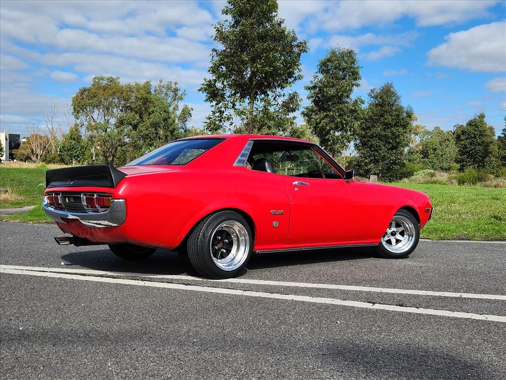
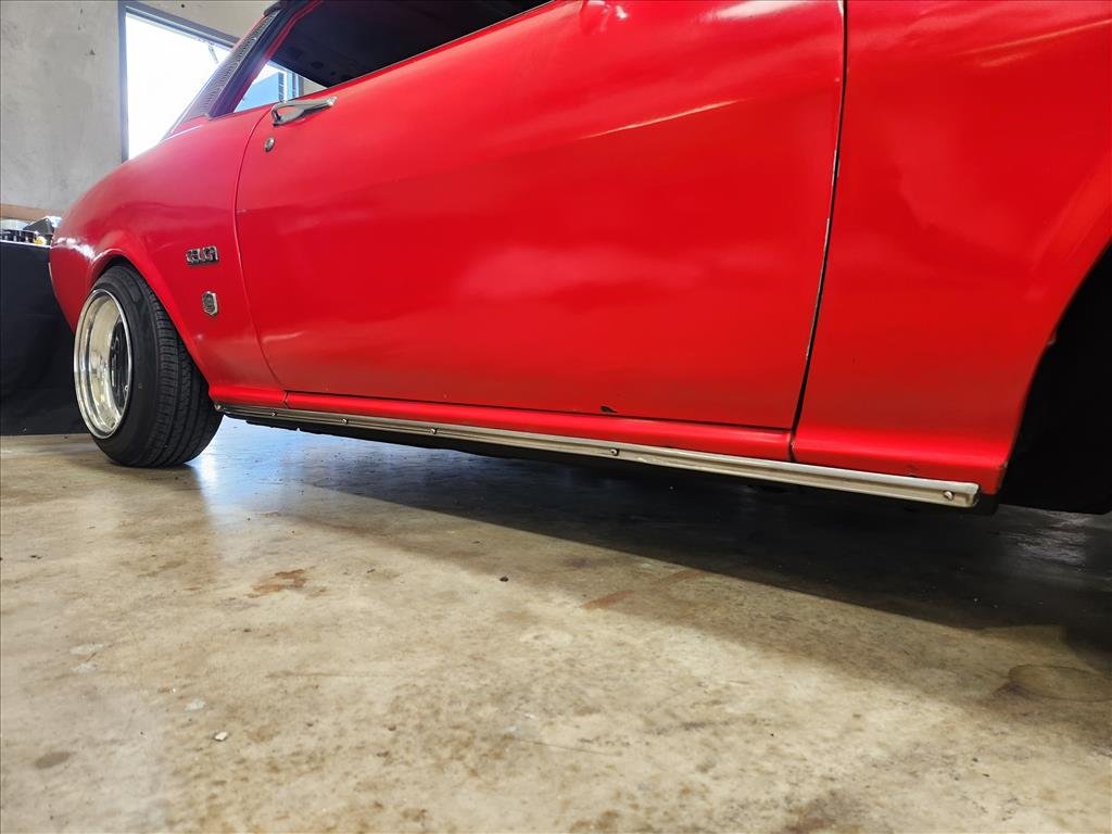
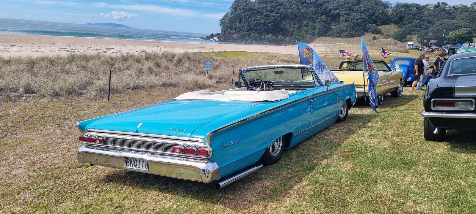
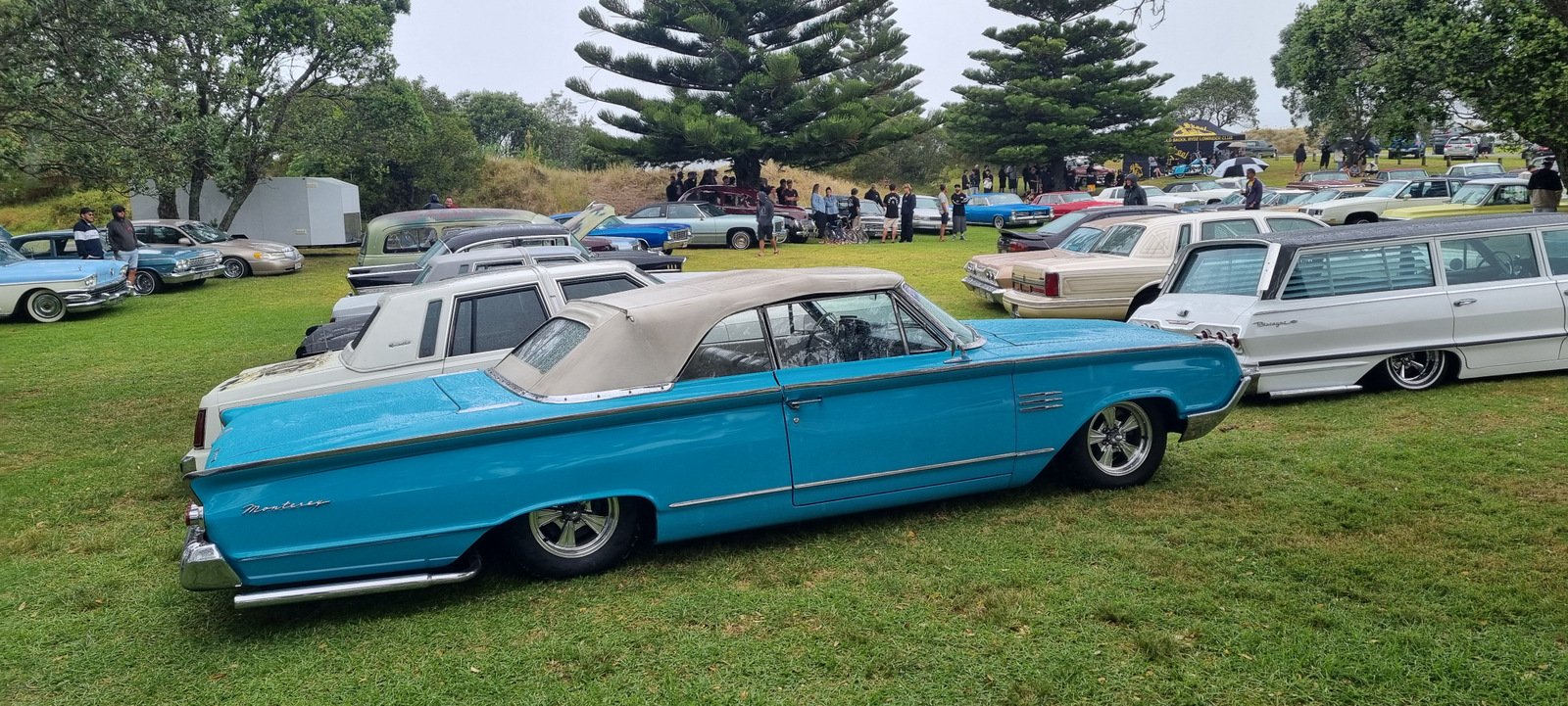
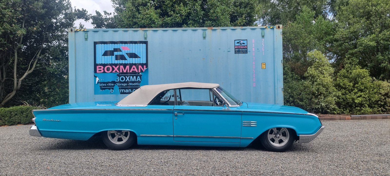
Made it up to Waihi Beach the Whangamata OK. Parked near the beach, and then in the slamfest on Saturday (bit damp that day). New paint is a big improvement.
2 points
-
This whole thread should be renamed where to weld the Coby in2 points
-
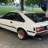
After a load of work, time and two new owners.. It's come back, I enlisted the help of professionals to make the super complex rear lower guards. Pulled motor out for valve grind and clutch and now debating whether to OHV and 1725 it, kinda glad this thing has come back into my life- always regretted selling it.2 points
-
Its got a 40 month warranty. And the receipt is now in a ziplock bag in a draw. Its anybodys guess if we'll still own the car then or not.1 point
-
Ha - another case of modern cars just making life so simple for us eh1 point
-
Okay, Scratch that. I took off one lead of the charger, and refittes it. Boom, fully charged light came on. /as you were.1 point
-
Yup also common for the water seal groove to disappear1 point
-
Four months to Hanmeet Alex. No pressure.1 point
-
Could be caused by a number of possibilities really, cracked housing, blown water seals, cracked plates. they usually still comp test fine too. Atleast you know it’ll be good after a rebuild1 point
-
I can always just remove the linkages or something at point of test. Correct me if I'm wrong but I think exhaust valves are only not allowed if operable from within the interior of the car ? I'm not sure and not bothered really. At this point in time I'll be happy if I can just adjust it with a lever in the engine bay. Got to get the car on the road first. Just bloody happy this bits finished!!!1 point
-
The shroud arrived, it'll need some trimming to suit but was cheap enough I pulled the manifold off and sat the turbo in place with the v band adaptor bolted on so I can start figuring out the manifold. I'd be a lot easier to fit the tubo without the air con compressor The downpipe is going to be fun and a lot of bends too, it'll probably will do a U-turn then sneak behind the manifold and down. @Raizer trimmed the Drain fitting and that now fits nicely (I'll need to clock the core to sort out the angles ) The sinco merge collector is quite nice, I might need to shorten it a little as its quite long and space is limited I've ordered some more steampipe short radius bends as I don't have enough. The Nissan genuine studs for the turbo are 40mm M8x1.25 and are $12 each, The Honda studs are 38mm M8x1.25 and are $2.50 each so I'll order a bunch of honda studs and hope the 2mm won't make that much difference1 point
-
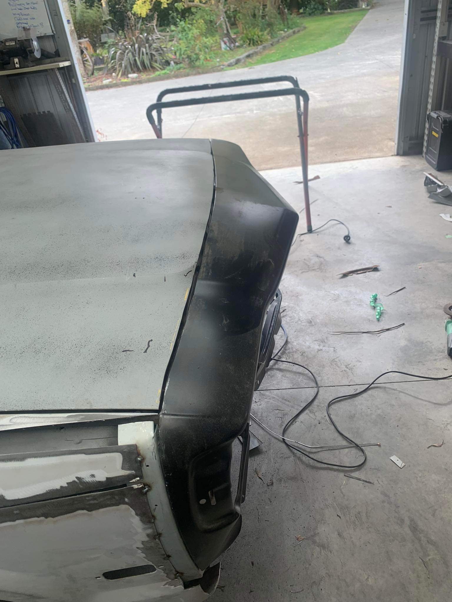
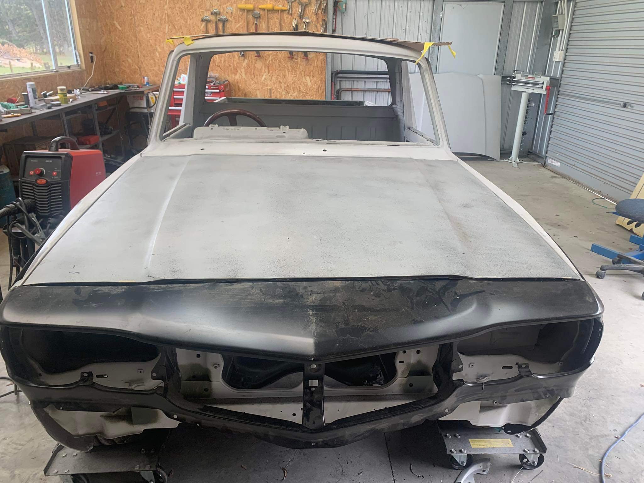
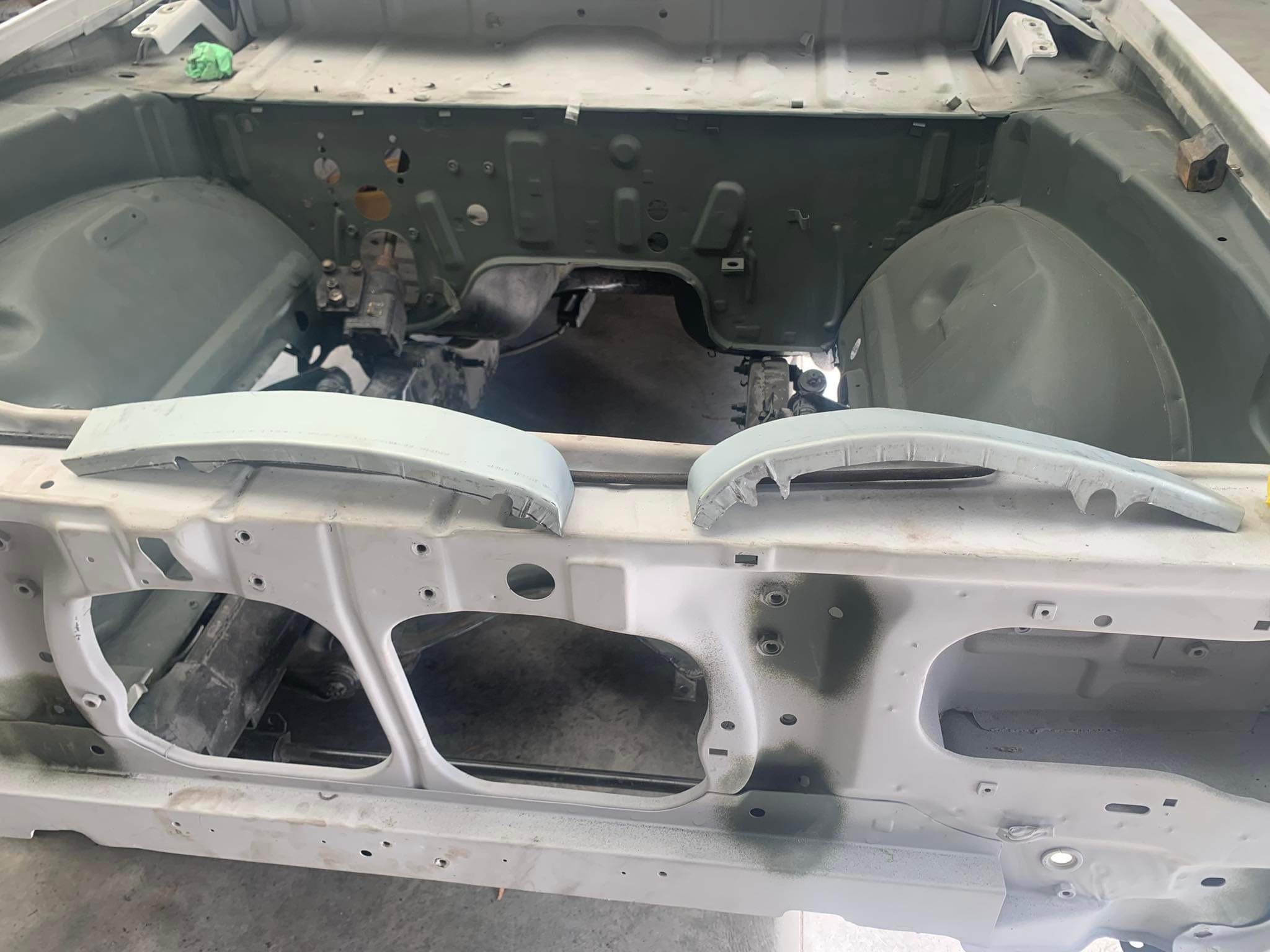
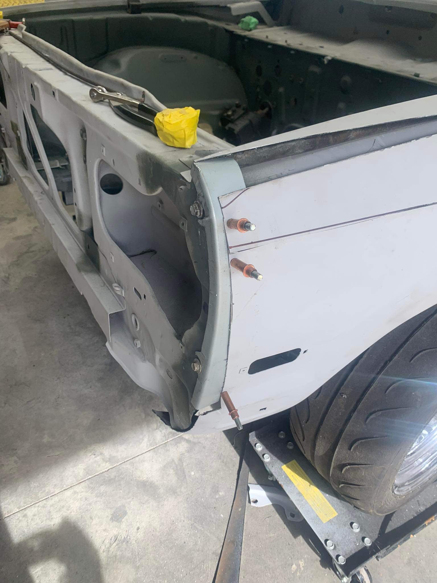
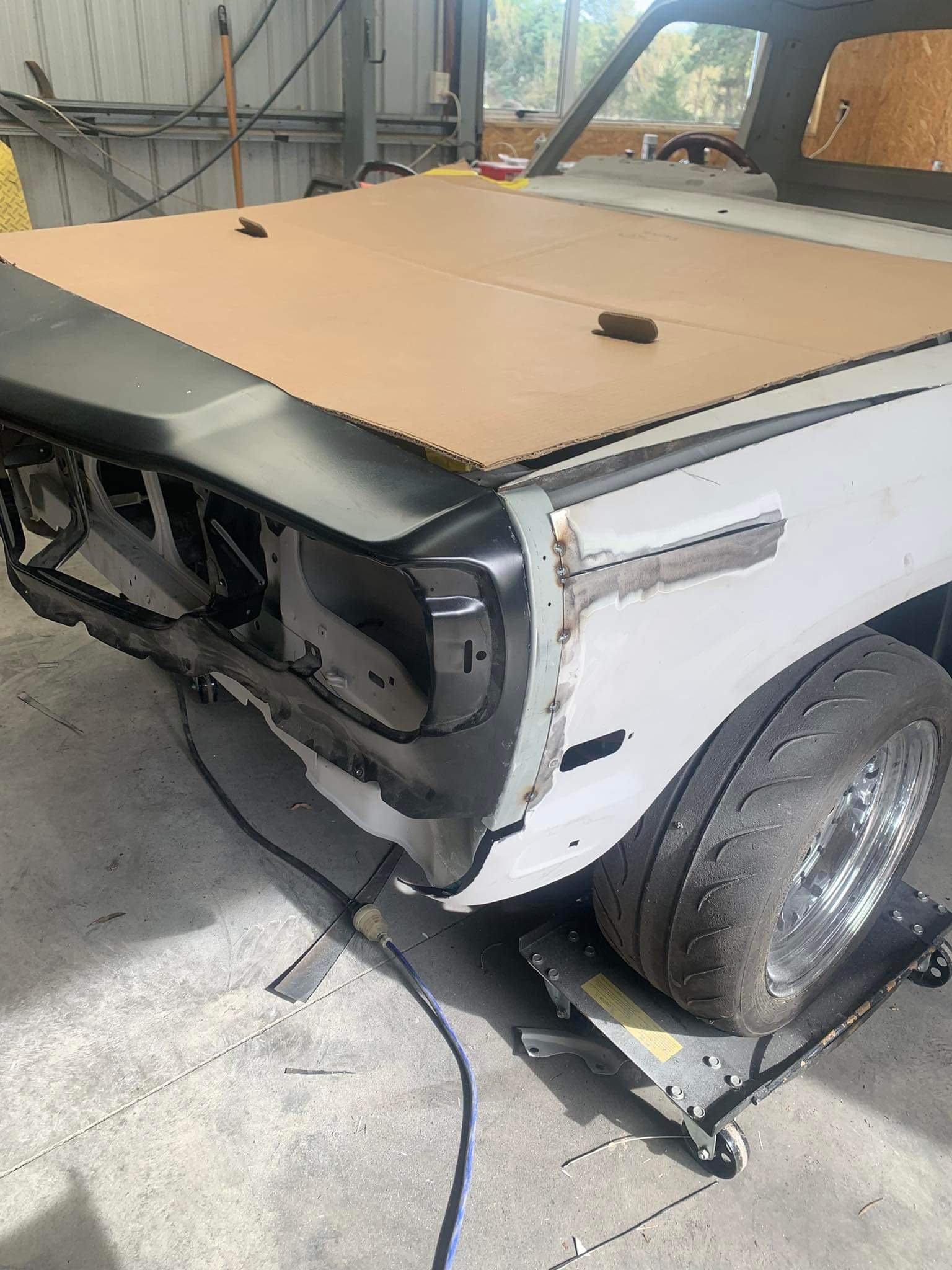
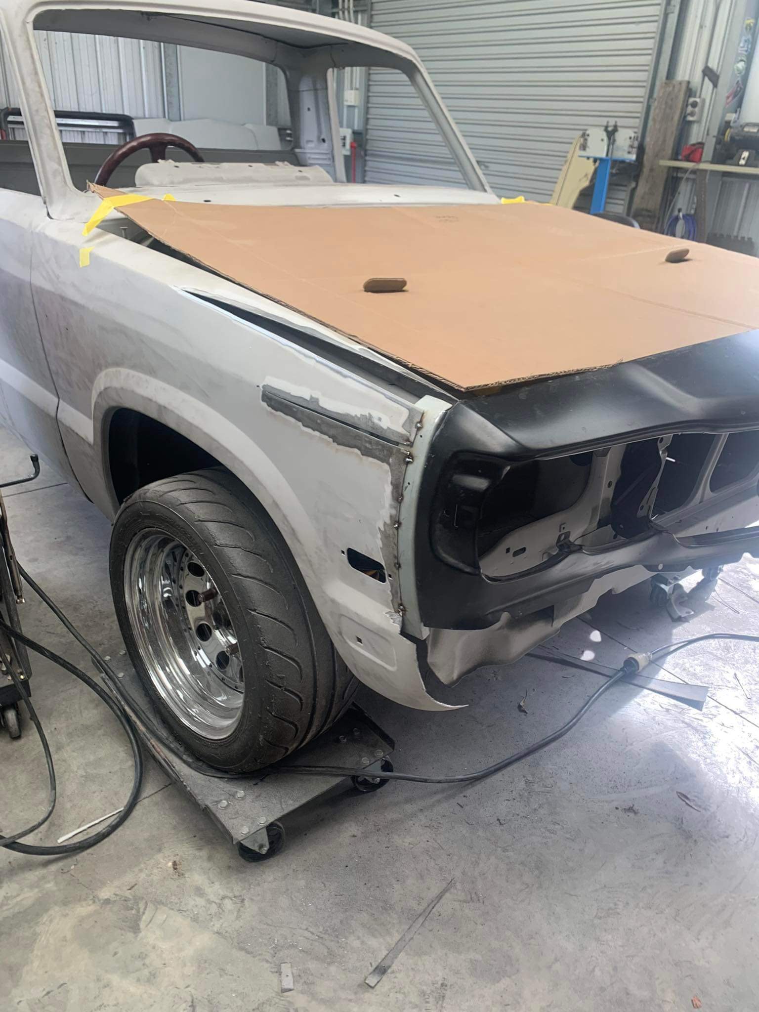
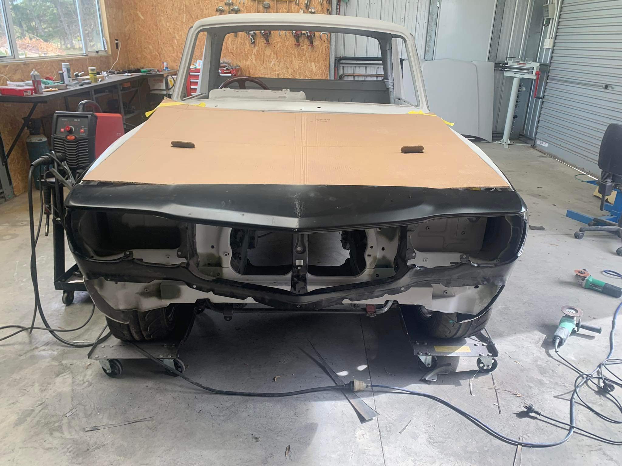
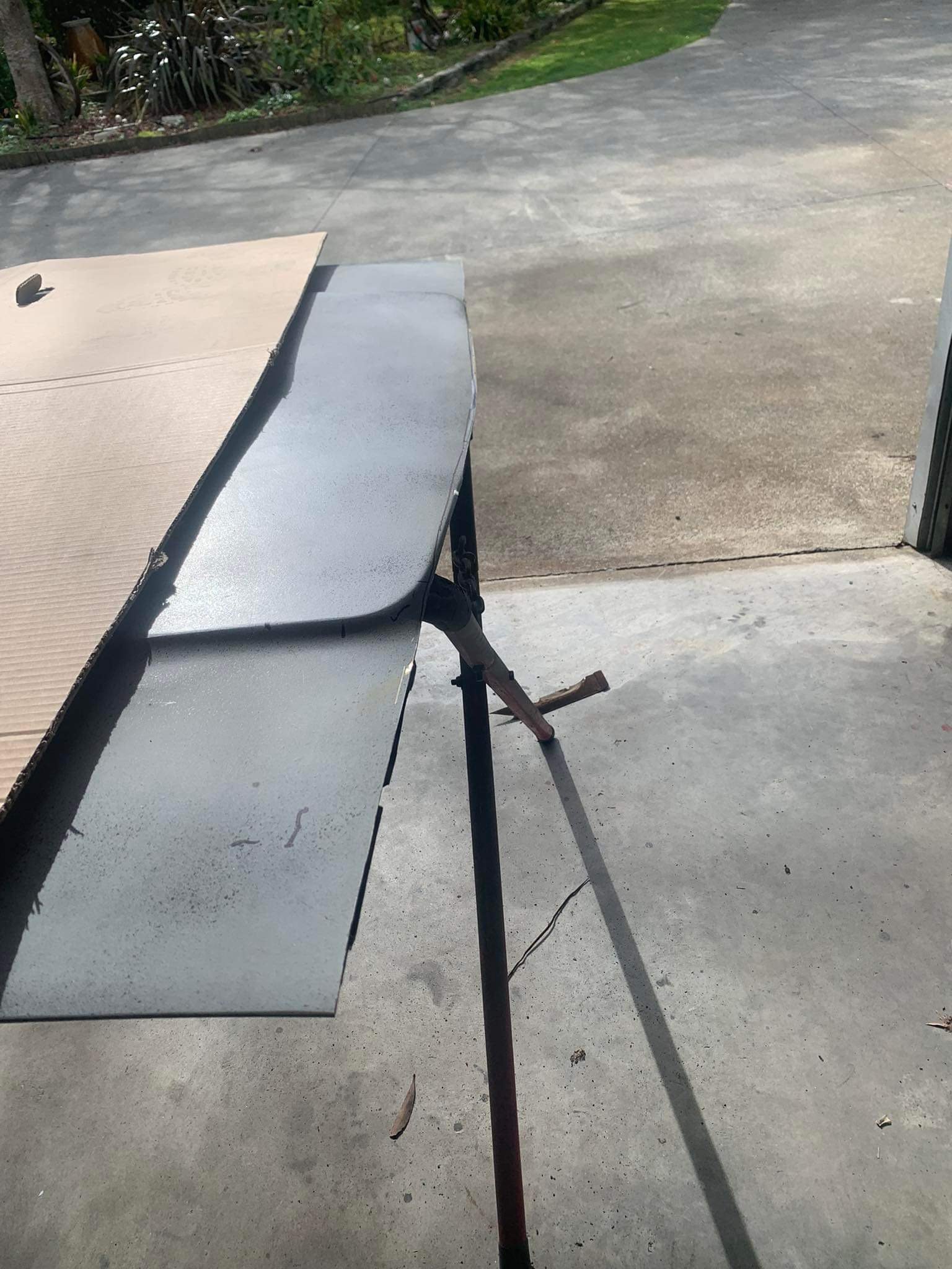
So the above teaser was me dropping the ute off to a panelbeater near palmy. this is his update pics. i just didn’t have the time or mental energy to grind my way through the stitching phase, or attacking the mint bonnet with a grinder. he has made up new flanges for the front of the guards , he won’t use the rx3 guards on this set up, all new steel. have also tasked him to fill over the fuel filler hole as I can’t utilise that once I drop tank it out the back anyway. So now I’m forced to drop tank it now instead of when I bag it. it means that I can carry on with the tubs when it’s back. I will end up using push button bonnet pins, hopefully they’re ok as a bonnet pin for road use. I’ll also fit a check strap as a secondary safety measure happy days
1 point
-
Ive been making good progress on getting everything wired into the fusebox and controlled by ECU rather than hardwired. I bought 2x 500mm coby hotdog mufflers which are currently just sitting pushed over the ends of the pipes on each bank. Quieter than just open manifolds but should be better once welded. Have wired up ECT, wideband, fuel pressure sensor. The motor was still idling really high (like 4200rpm...) with fully closed throttles, even after setting everything to fully closed. I couldnt figure out why until I noticed that my 2x lower intake manifolds dont quite cover the edge of the circular holes which must be an idle air bypass. It was only by a smidge, so gooed the gap with some silicone and solved that problem. My current issue is that the cam angle triggers arent being picked up properly. This motor uses hall effect sensors on the cam angle sensors, and the voltage they output is too low for this ECU to register correctly. So pullup resistors are needed, which I have wired in. But stilk not working it seems. Some people have suggested wiring them to the 8v power supply rather than 5v supply, and this boosts the output voltage. But this stuffs up my loom a bit, as the 5v supply on that plug branches to a few other things as well as the triggers. So, another annoying problem, but not insurmountable. Just soaking up more time on little bits and pieces than expected. But thats always the way I guess!
1 point
-
I actually have a massive boner for early Jimny 2-strokes. An old guy that comes into work has one, I'm trying to get put into his will so I can get my mits on it. Anyways, I have done a bit more on this thing. Don't laugh at my lack of wood working skills, I fucking hate working with wood. So I made the front guards, bit of a weird shape to try and make out of wood, mostly because of my being a tard and all. A bit of fiberglass & resin, a hint of bog, and they should come out pretty good. Then I got started on the bonnet, which is probably the most complicated shape on the thing. Added some wooden ribs, and a couple of dowels as reference marks, then put real thin MDF under them to keep the foam in, then filled the gaps up with foam, then carved the foam with a hacksaw blade and Stanley knife, then chucked a couple of layers of fiberglass over it, to give me a firm base to work with. It actually came out really close to correct, so will need very minimal amounts of filler. Next was lights. My B-I-L used OG dolphin torch reflectors/lens' on his Jeep, that he cut down to the correct size. New dolphin torches have four round LED bulbs in them, so don't look anything like a head light. The only torch I could find that was roughly the correct size, and also sort of looked like a real headlight was some budget items from Bunnings. I pulled them to bits, linished & sanded the OD of the lens down as small as I could, but so that the reflector still fit into it. I then cut the holes in the body to suit these. The front grill will hold the lights in, and also down size them to roughly the right scale size. I also found a Toyota badge that used to be on my 86 (before I got a legit one) that's pretty damn close to the correct size for this, but not sure if I will use it or not. The back lights were way easier, I found some LED lights on Ali that were the right shape and scale for this thing. They are meant to be in corners of the bumper IRL, which seems silly, as they would get smashed real easy. I added in a bit of wood roughly the same shape as the real bumper, and set them into this, so they are a bit more protected. There will be a steel bumper under them mounted to the tow bar in the future, so it should be quite a challenge for the kids to smash them. That's pretty much where I'm up to. Regards, VG. xoxox1 point
-
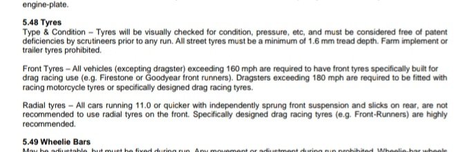
Yeah it's not great to mix radials and bias ply tyres, it can make for some interesting handling Nzdra rule book says
1 point
-
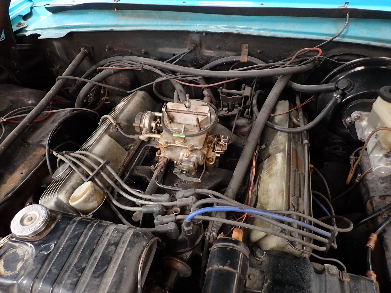
Lets see Muffler replaced, I left the other side there as it didn't look too bad Pulled the door trim off to put a speed nut on the self tapper holding the wing mirror Got some Rock Auto Looked at a grotty engine
1 point
-
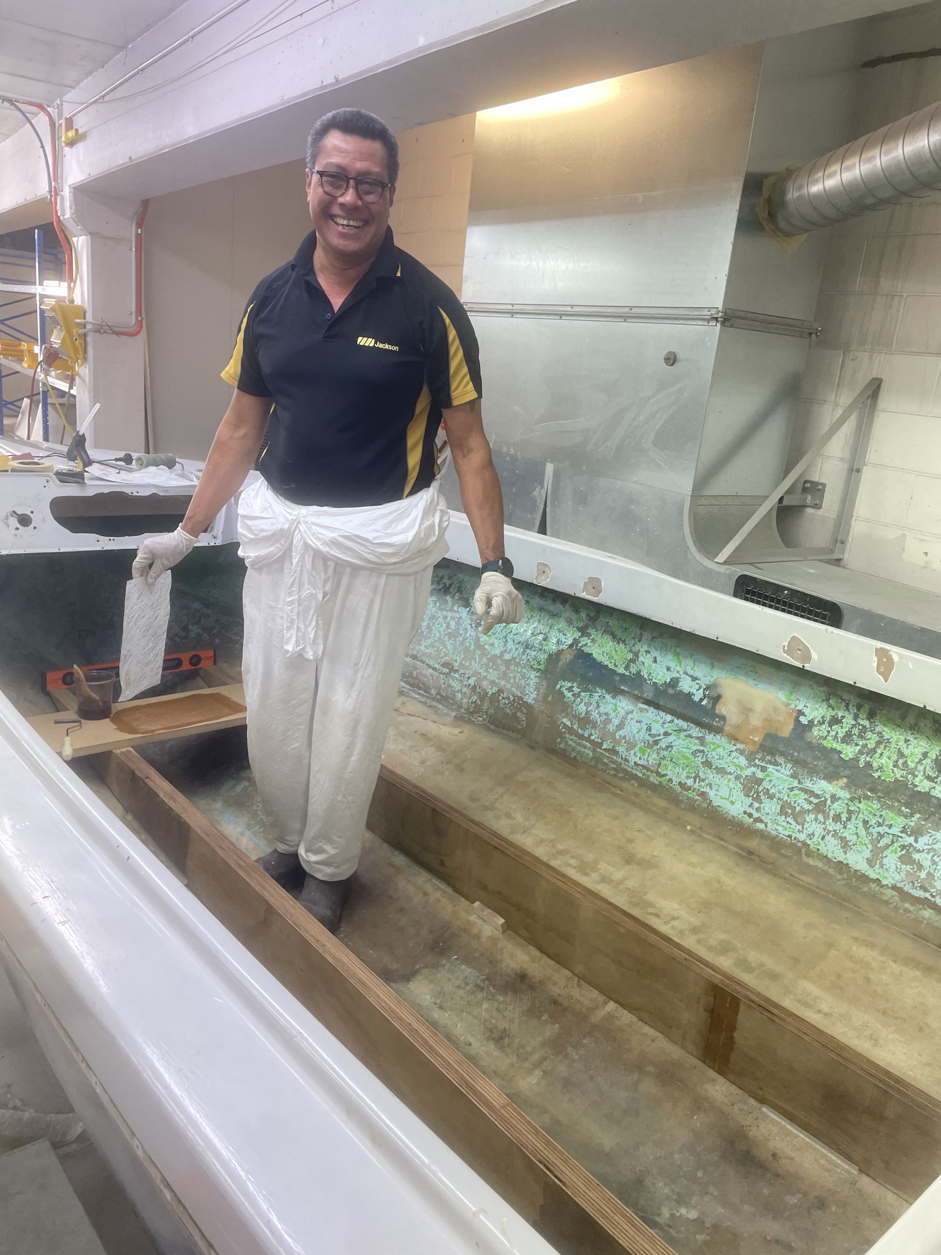
New beam’s laminated and machined from @Ned’s 3d scans, amazing outcome for such a big surface and “low cost” scanner Realising I don’t have enough talent for structural fiberglass work, talented uncle Neemia from work took over and is doing an excellent job, a layer of glass is over the inside of the hull and the beams bonded in place to be laminated over the top of.
1 point
-
1 point
-
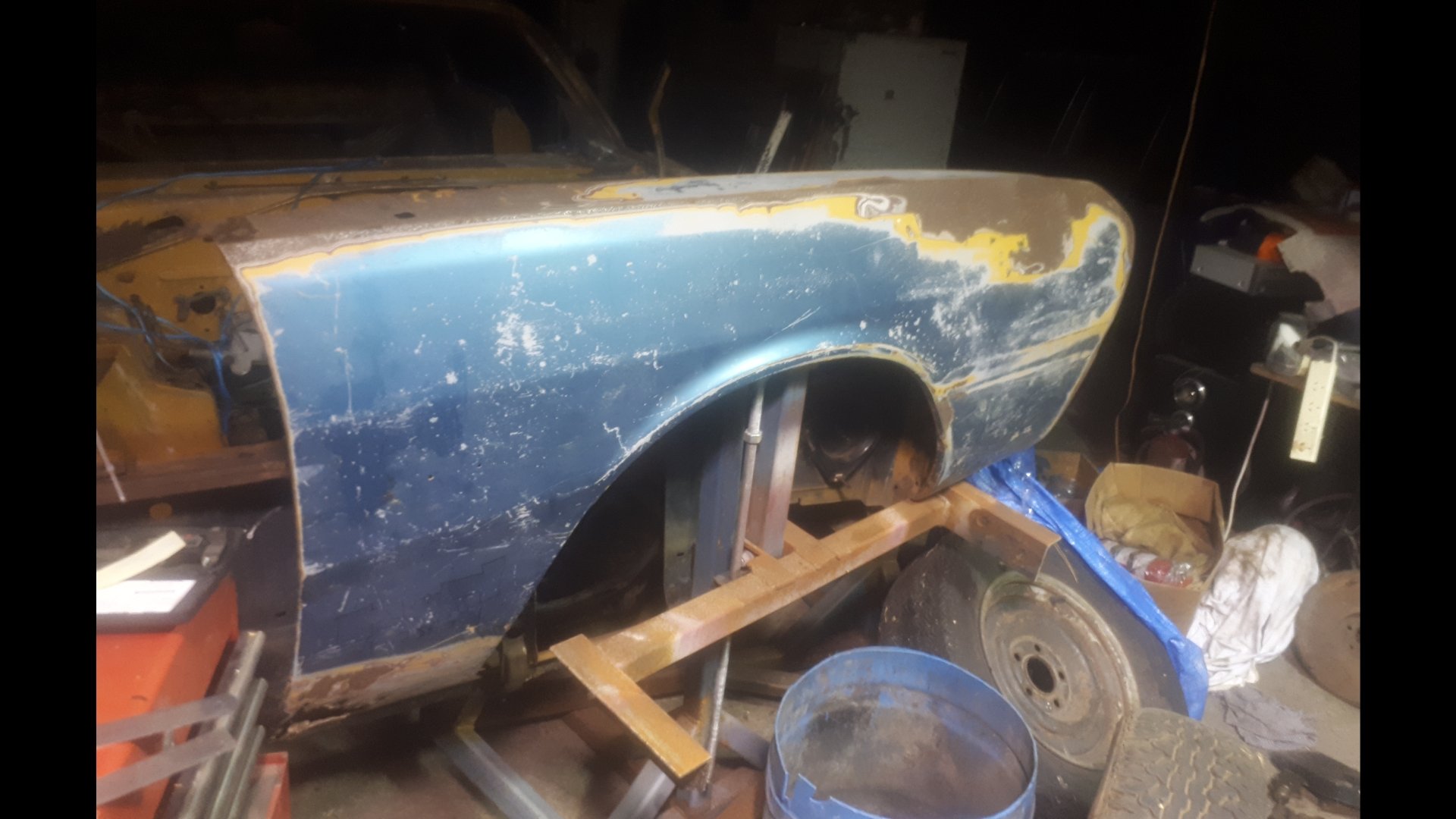
Im still thinking about this once in a while. Tracked down a less fucked right front guard. It was up welles ways. @Goat kindly let me use his house as a freight forward depot. The seller dropped it off, and a mate who was passing by collected it the next day. Picked it up tonight. Defo needs a wee bit of work. But i can buy the inner and outer bottoms off the shelf from Automotive Panel Craft in Oz. Thanks to @Classicdat for lugging it south for me too!
1 point
-
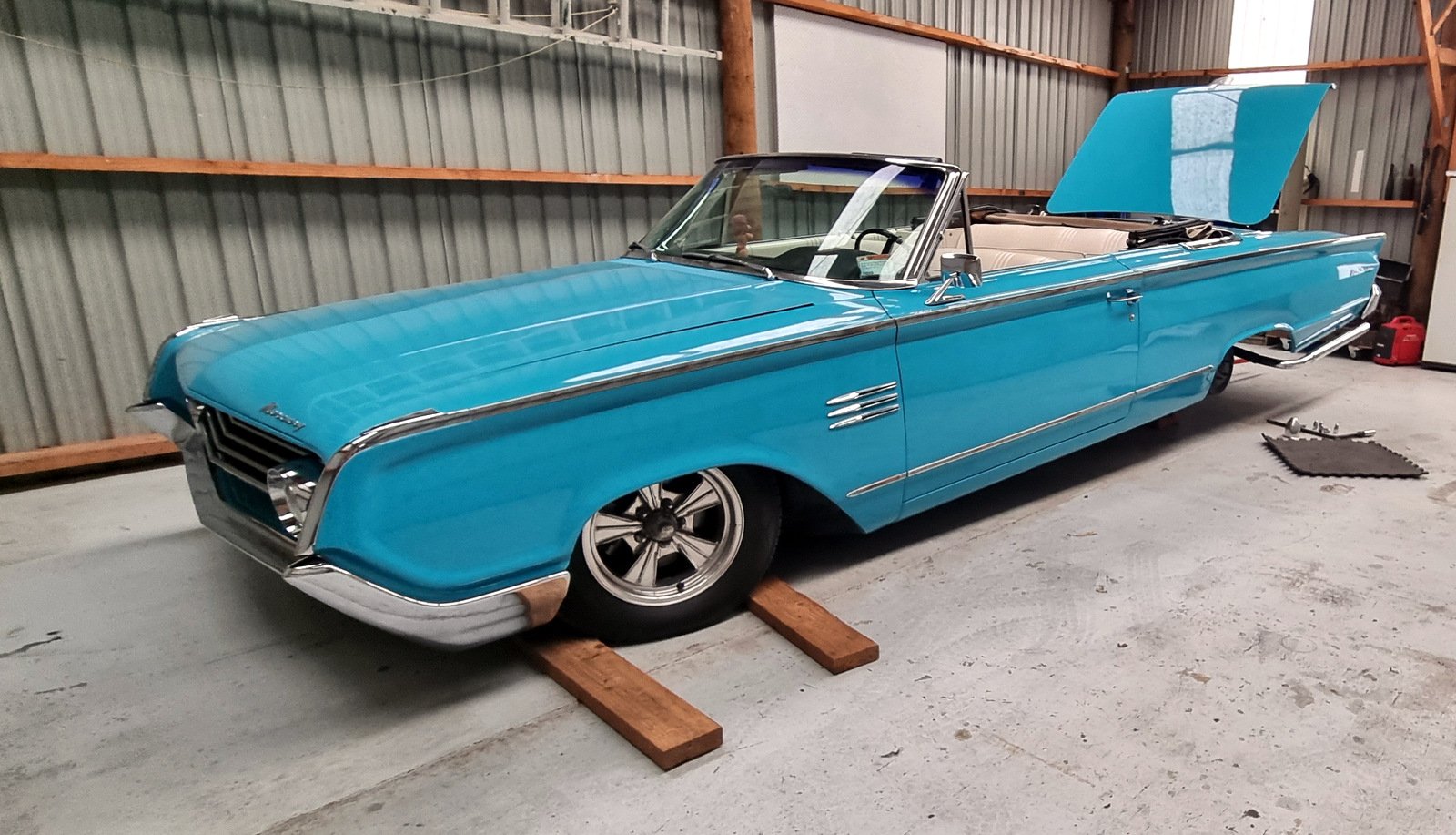
Collected from the paint shop on Tuesday basically a closed door repaint in the stock colour, nothing fancy Had a bit of reassembly to do, the bellflower pipes and the back seat and associated trim. Also had to find a bolt to fit one that went missing from the convertible top linkage (you can see the disconnected link in the photo above) Might have to hit up @ajg193 to make me a proper one as it is a special shouldered design. Looking it over the rear tyres looked a bit sad, so I pulled the wheels (which needs the tyres deflated) and got that sorted. WOF acquired today so have paid rego too. Just needs a bit of a clean up for the Beach Hop.
1 point
-
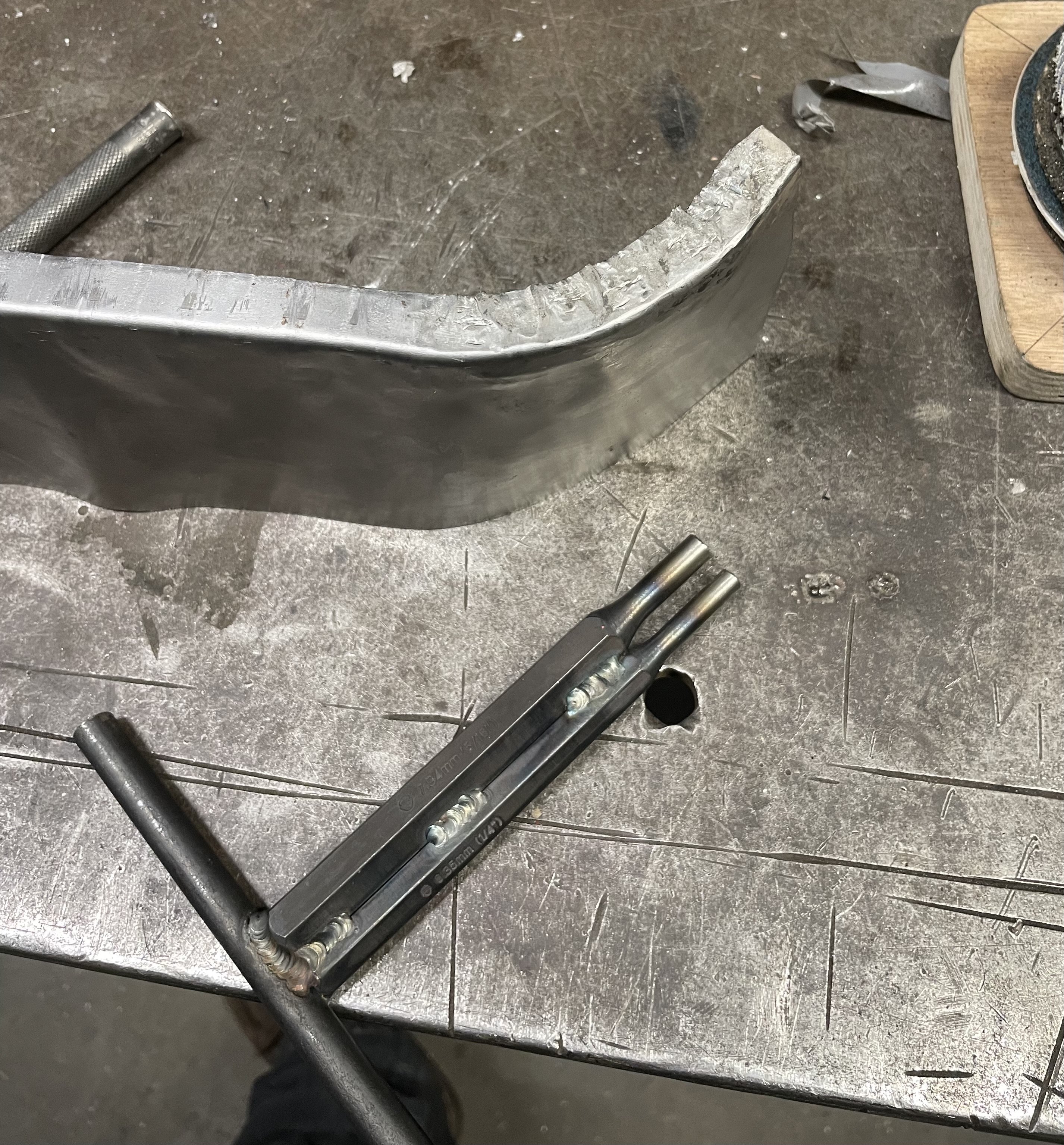
I glooped the two halves together, bolted them up, bolted the tailhousing on and let it set. Following morning it was bolted onto the engine, unsurprisingly a bit heftier with all the gubbins placed back within the box. Its about 9kg heavier than the standard imp box. I then started to fit the first part of the gearshift linkage. The first of those snazzy universal joints, handily available in a diameter to suit the shifter shaft on the Subaru box. I just needed to add a small locating hole for the grub screw... Universal in place.. Engine and box were then bolted back into the car. This bit is so quick and easy when using the 'engine stand 2000'. It takes about 10 mins and I'm getting quicker. It'll be slower when there's shift linkage to undo and driveshafts to slip out of the way. But at least the main heavy awkward part is actually easy. That lot in place I took some pics. Its neat to be able to look out from the one of the lounge room windows down onto the workshop floor and see this... With that lot in place I was able to suss out the angles I could get away with, as shallow as possible and allowing for the handbrake mechanism. I had this old imp gearstick assembly that @dmulally kindly posted over to me. Some previous owner of the car he got it from liked painting things. Everything. Multiple times... I scraped all the layers off, took it apart and cleaned off the dirty old grease. Discovered it had been cobbled together from two old shifter bases. It was originally a very early Imp unit when the very first cars had an automatic choke, which often proved problematic. Hillman then changed the cars over to a manual choke with a nifty little lever in front of the shifter. This mount had been added to the early base. Which means they must have chopped up a later baseplate to get the choke mount. Why they didn't just fit the entire newer base plate I don't know. But what I had in front of me was a frankenstein of base plates with barry spec welding and fixes, but also including a not too badly made bronze bush on the lever where there is normally a (wornout) plastic bush. I had a couple of shift rods to choose from. I chose the least worn. Moving back to the gearbox end I machined up some shaft ends from stainless bar to suit the universal joints. I had some stainless tube and welded the ends in place on the first shaft that runs from the gearbox universal down to the tunnel. Now I needed a sturdy, slippery support to mount in place of the second universal joint. This will not only take back and forth movement on the shaft but also a bit of thrust loading created by the angle on the connecting shaft. I had already bought a lump of slippery hard engineering plastic with this application in mind when I had ordered the plastic for the flywheel thrust bearing a while back. It was bright yellow. Luckily not seen under the car as it would clash with the blue paint. I put a hole in it and machined the outside down. Which also created a pile of pretty swarf.. Then reamed it out to 1" Still a bit tight so out with the adjustable reamers.. until it was just right... Then made a stainless cradle .. The cradle got some wings welded in place and I dug the rivnut tool out.. Mount now bolted in place in the tunnel I had to chop the last tube to the right length, weld on the end and bolt the universal in place.. The front end below the shifter was was standard imp stuff and this is where problems popped up to throw a medium sized spanner in my workings. The side to side gearstick movement across the gate was minimal. Ridiculously so. Like about 1". Or 25mm in new money. Yet the fore and aft movement was about right. But quite stiff. I was contemplating why this was so and what I could do to remedy this when I also noted that 1st gear was where 3rd was and 3rd was where 1st was. Poos. Four years ago when I had compared the Subaru gearshift pattern at the box to the imp unit I thought they were exactly the same. But I had not accounted for the reverse rotation taking place under the imp gearstick. Also I never really thought much about how little of rotation the Subaru box needed on its shifter shaft to shift the internal selector across the 3 rods. Its a tiny amount, like 3 degrees say. Whereas the Imp box has a shorter internal selector and requires more rotation at the shaft. Hence the Imps gearstick knob only moves a teeny bit when coupled to the Subaru box. But the Subaru box has a standard/similar amount of rod movement within (ie 1-2 and 3-4th) which was going to make things trickier to fix. Simple linkage/leverage multiplications that is easier to see than explain. Sorry if your brain hurts. I had to hurt my brain a little bit to suss out a solution but there was only a little bit of smoke. The reason the scooby box is different becomes obvious when you see the scooby shifter setup. Which luckily I can show you because last week thanks to @Leone I was put onto a local fella to me who happens to have many old Leones and Brats kicking about his property and he had a spare leone front wheel drive box that I wanted (always handy just in case...) His property is amazing!!! Long 4wd only driveway up to a ridgetop house with stunning views out over Tasman Bay. Old leones just kicking about... Luckily we have our trusty old 4wd Hiace and that became the days gearbox transporter... Box on bench. Look at that shifter mechanism... The shifter rod attached to the gearstick only rotates a tiny amount when the stick is moved sideways across the gate. But the rod moves 10mm in each direction when shifting for and aft. Simple. Robust. Very Subaru. I can't copy it though because I have turned my box 180 degrees. No matter where I put my pivot point (below or above) I'll have one of the planes working backwards. So I decided to build a new shifter base setup. The most important thing was to reverse the rotation so the gearstick pattern is correct. The imp pivot point needed raising to allow the offset shaft end to be rotated to above rather than below the centre line, so reversing the across gate movement. I would add the ability to adjust both rotation and lineal movement. Started with a new pivot cup because I was not happy with the worn and Barried pressed steel item.. I dug out a large lump of steel bar... Chopped out a square and cleaned it up in the mill.. Big drill = big hole.. Rough machined out a cup shape. Cut a form in cardboard to suit the brass ball and used a die grinder bit to finish the shape... Grinding paste time... Slots for pivot pin.. Lightened the lump down.. Built the shaft up with weld and machined it down so I could add a lower pivot point. Milled some steel like so.. Welded a boss on.. New socket for shift lever ball end... Cut out Barrys previous workmanship... Machined up some spacers and a base plate.. Welded up a little tower (my stainless and steel tig welding is definitely improving, helped muchly by realising that not being able to see what I'm doing does not help much and finally admitting to my age and buying some reading glasses....) Welded tower to base.. Now all together please... Bolted together. You can spot the adjustable rotation, which the spacers allow for, along with adjustable pivot point. In place... Yay- it works! The shift pattern is correct and the action is much smoother. The spring loaded indents on the internal gearbox shift rods are quite stiff, which I noted was the same on the other box with its stock shifter. Its a bit baulky to push past the synchro baulk rings into gear but I think will feel better when the gears are actually rotating. There's certainly no slop in the system and it feels very mechanical - not rubbery. I now note how much flex there is around the shifter base in the imps tunnel (granted a very rusty shell..) Its something I might just try to stiffen up on my blue Imp when fitting this lot in. Phew. That was a little mini engineering mission I was not expecting but that's this project in general1 point
-
1 point
-
Video of stationary full load cooling efficiency test please1 point


.thumb.jpg.570970b401ac8d26ce9af7c1bf2bd8cd.jpg)


.thumb.jpeg.384ff72c8d2b0ee0d34a7bdedb55bdcf.jpeg)


This leaderboard is set to Auckland/GMT+12:00