
Leaderboard


Popular Content
Showing content with the highest reputation on 08/28/21 in all areas
-
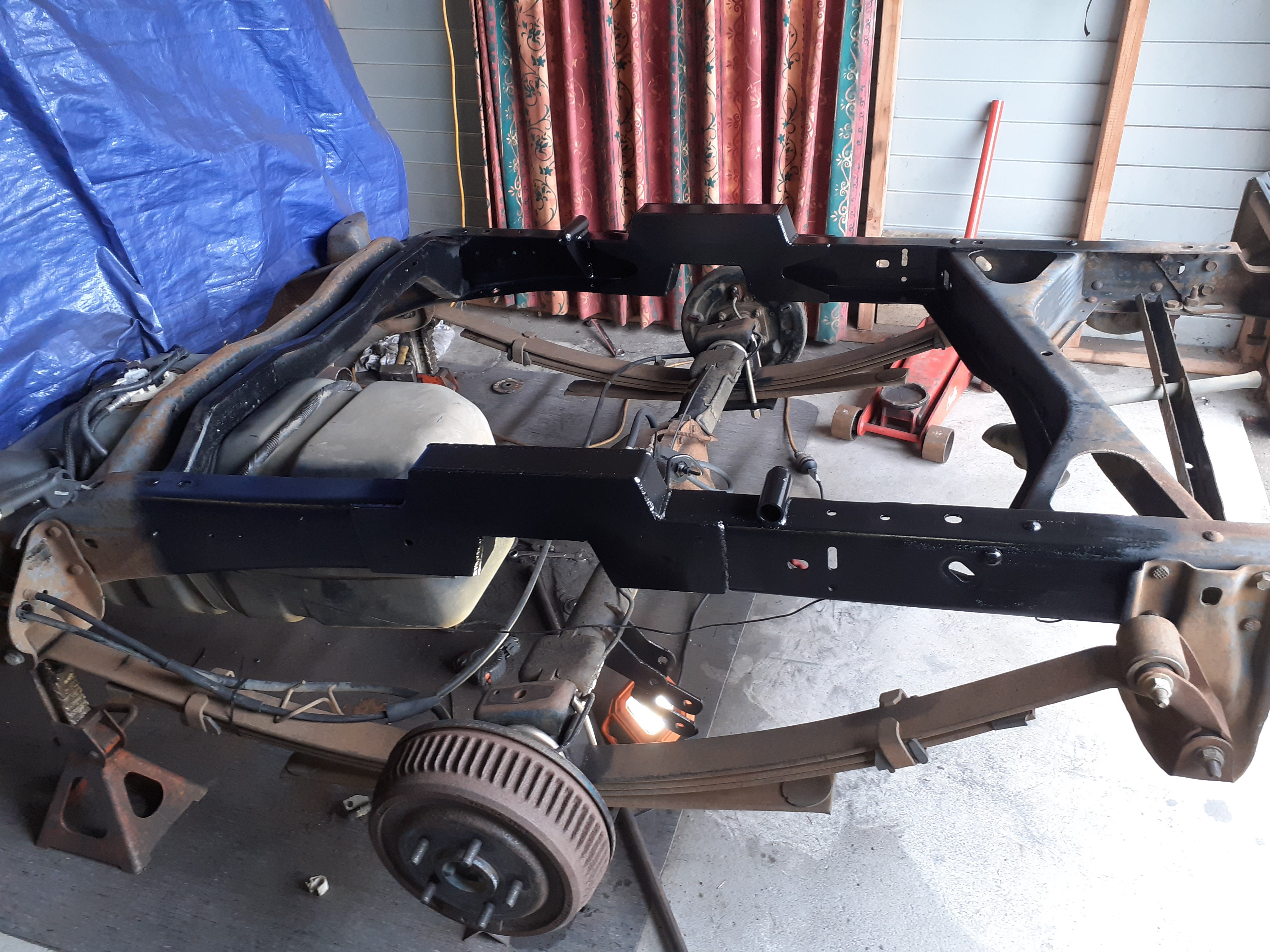
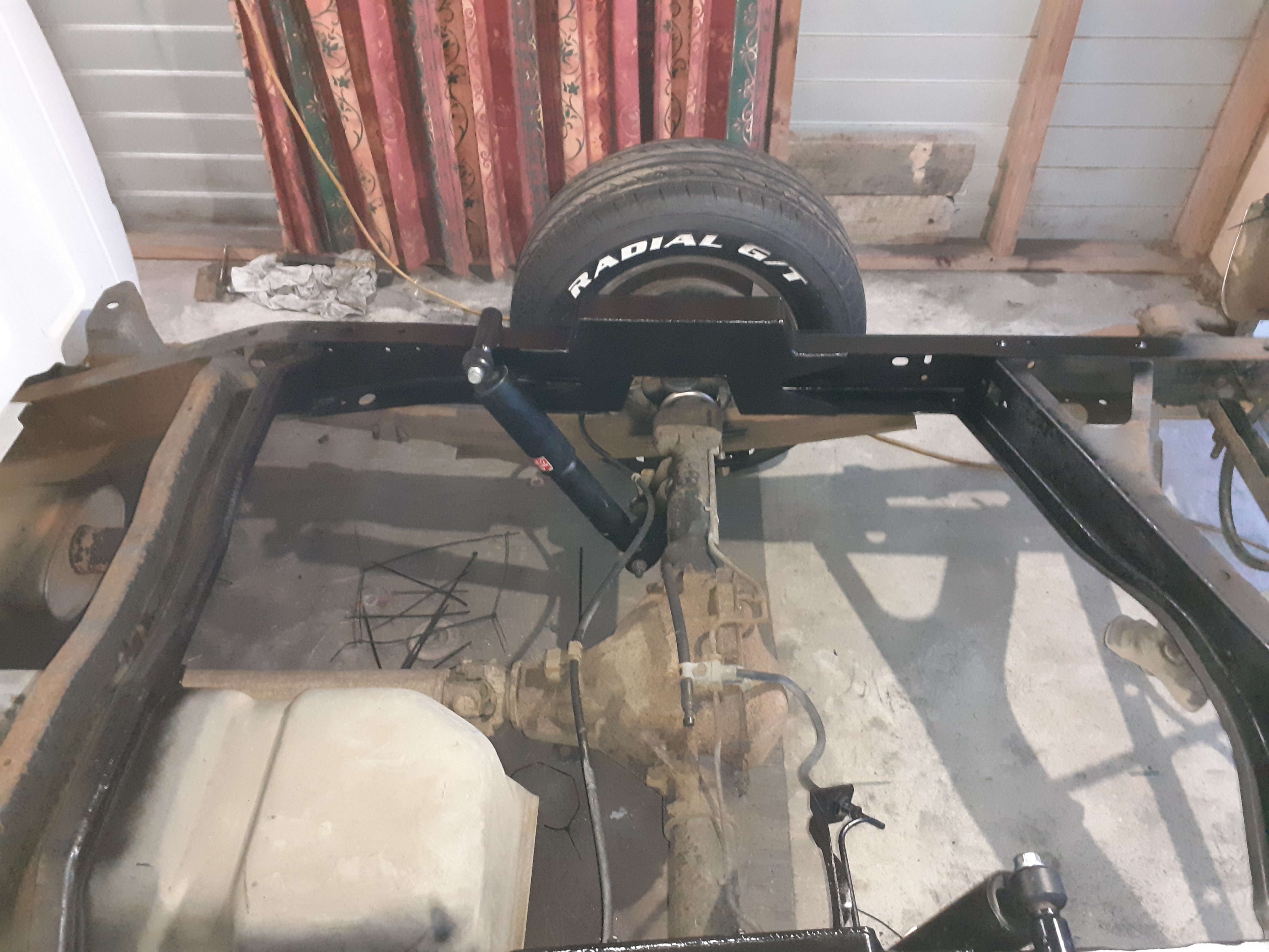
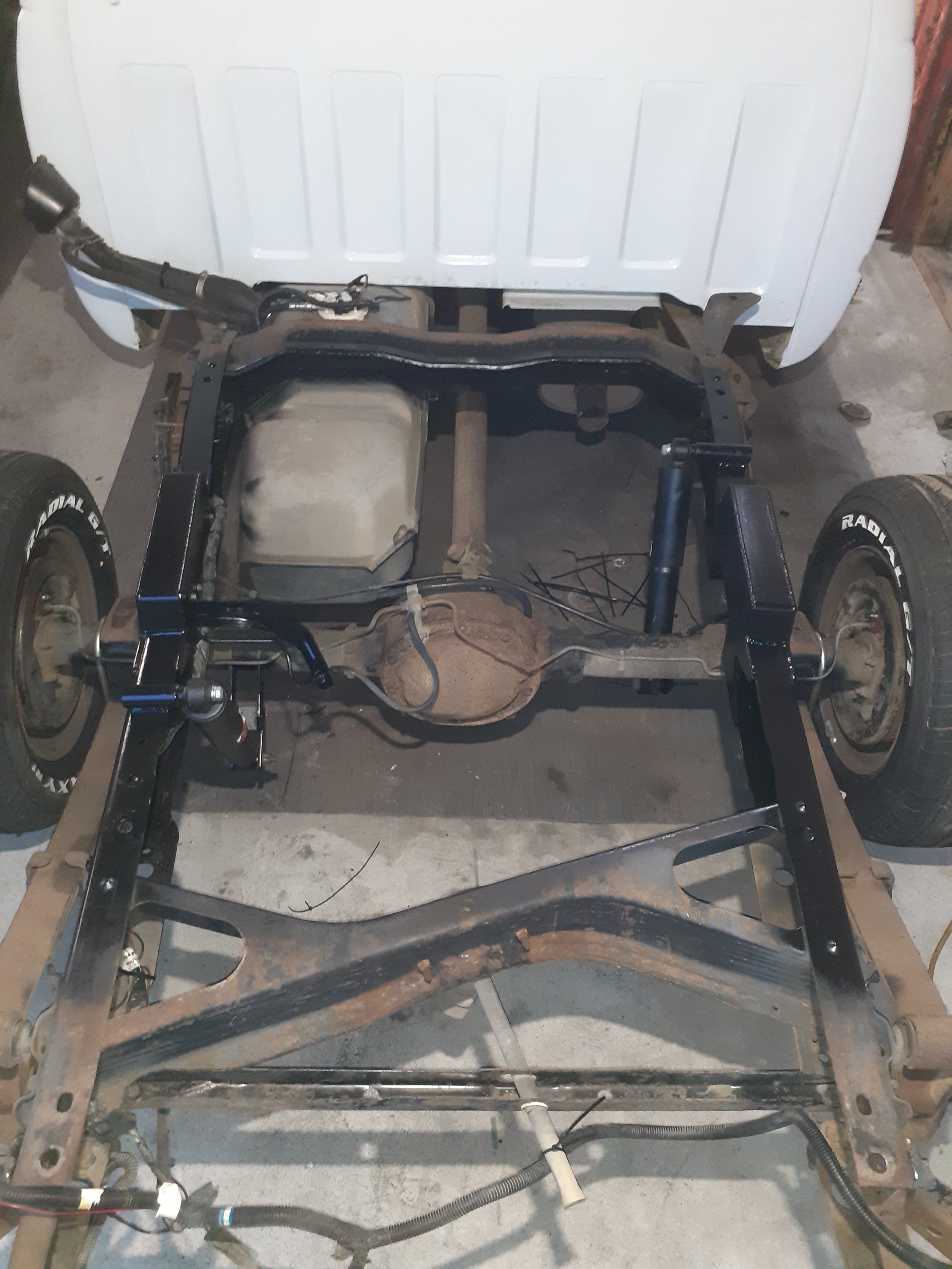
i forgot the finished notch pics
 10 points
 -
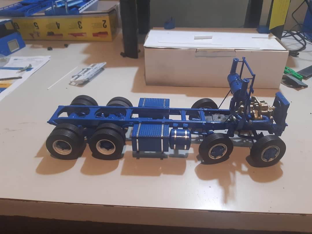
Chassis coming together slowly. Lots of scratch building
9 points
-
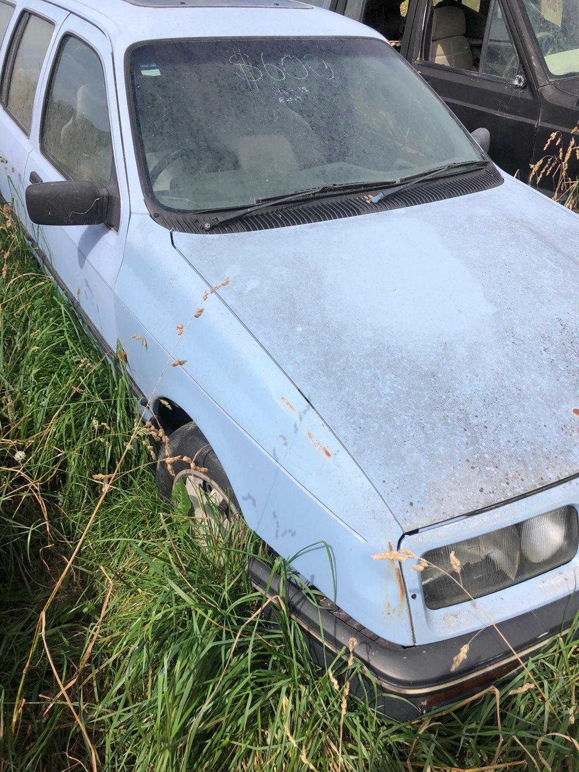
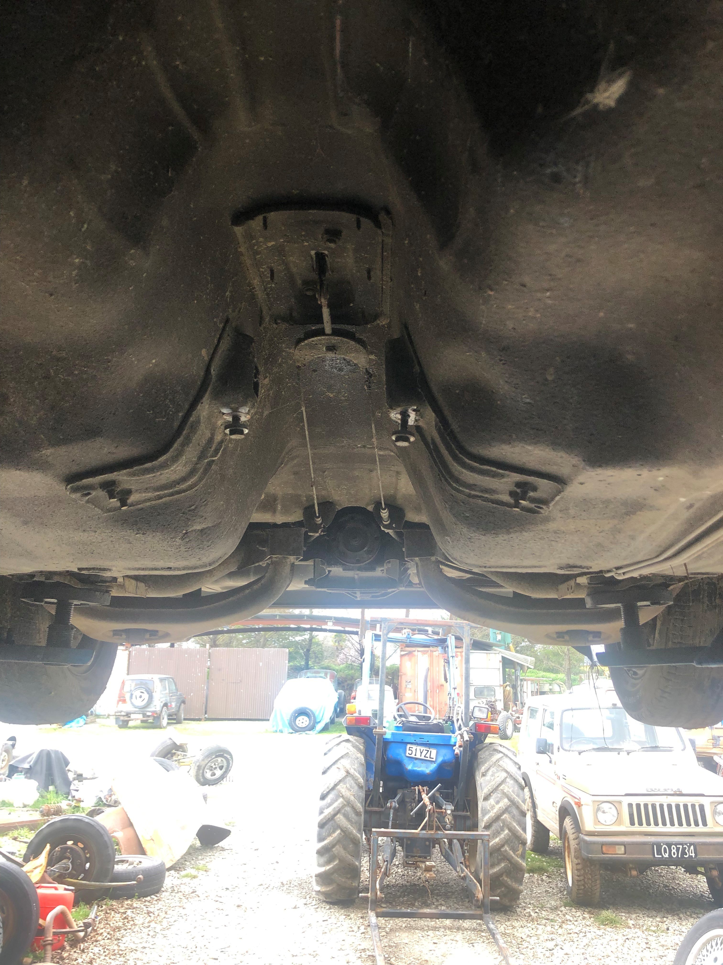
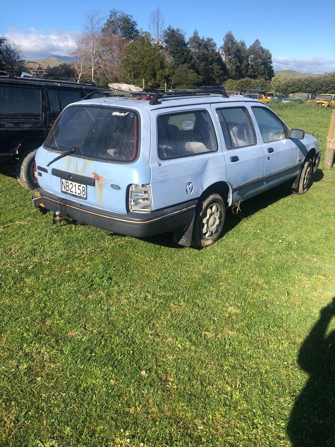
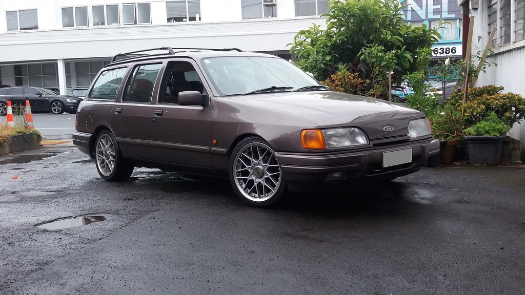
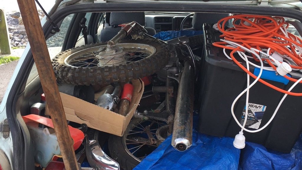
So whats even better than owning a Sierra? OWNING TWO!!!!!!!! (Badoom-tish!) I've always been open about my preference for the Mk1 Sierra's over the Mk2's and have been idly keeping my eyes open in case one became available. Karl (as always) has had his ear close to the ground and knew of a few in the area that might/might not be available. Then Dave up in Nelson ( @avengertiger ) answered a query saying he had a rolling chassis lying around the paddock at work.... He even did the honest decent thing and pulled it out of the weeds for a look at the undergubbins (while @- i5oogt - was in attendance) To be honest, it actually looks in better nick than mine........so due diIligence was performed (namely txting Karl and asking lots of stupid questions) and the call was made to grab it.....so now we wait for this crap lockdown shit to end so things can happen. Original plan was to hit any rust on this shell so she can sit in storage for a while until the time comes that the Mk2 can no longer survive a warrant, then a quick Engine/Box swap and we are back into it. But.......now I'm wondering about something a bit more ....exotic. @Carsnz123 (while answering an EOI for some Saaaaab work) has suggested either a Turbo Carbed Pinto (Weber 32/36, Regrind the cam, T25, 8psi) or even a 3SGTE (of which there is one currently on the book of faces.....) Decisions.....
7 points
-
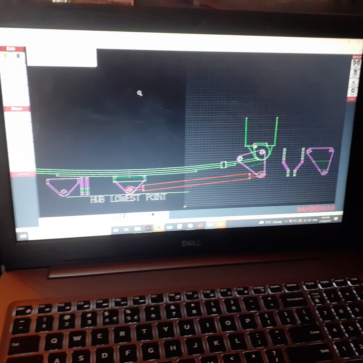
Phew- been busy. Lots done = update time. But to save my sanity I might do it in two lots. So as per @GregT bit of information above I looked into motorbike oil pump chains and yeah- bugger all have tensioners and they actually run quite loose. I then decided to scrap the idea of spring loaded tensioners because even with the ones I had they were still a bit awkward to fit and didn't quite work in the angle I would have wanted. So enter stage left my new adjustable tensioner device... which fits like this... The bolts that clamp it down are actually accessible from below with the sump plate removed so once the chains wear to a point that I'm not happy with I can tension them independently. The will be nyloc nuts replacing those normal nuts on the tensioner bolts when the final assembly takes place. So with that finally finished I moved on down. The sump cover. It has to be fairly beefy because it could see some hits plus the engine will rest on it when on the bench. It has to be alloy so It can be used as a useful heat sink to pull heat from the oil. It has to look cool for when the Barries look under the car. So some fins were in order. I bought a big lump of alloy from Ulrich aluminium. That hurt. I put it through the old table saw and did some rough cuts just to save on time milling... Into the mill and did milly things. It was going to take bloody ages thought so I made a new tool which I shall call the DDC. 'Dewalt drill control' ... It could always be an MDC. Makita drill control. My cunning design is adaptable. In action... Groovy man... Then the sides taken down... I stopped there. The bit that is left unslotted will be machined to suit a recessed sump plug. I wont do any more until I finish the front cover below the cambelts where I'll also be adding some engine mount points. Next up was to finish the adaptor plate that connects the engine to the gearbox bellhousing. I had machined a bunch of pedestals to an exact length I had worked out to suit the positioning of the spigot shaft on the end of the first motion shaft into the spigot bearing. These pedestals have been machined on the gearbox end to locate within the dowel like spot faced bolt holes on the bellhousing. This way there was no chance of any float in any direction - the box would always be perfectly concentric to the engines crank and the bolts are really just clamping it. I bolted it all up together... Then cut some strips of 4mm alloy plate and started bending them to suit. Connecting the pedestals... Once I was happy with the fit up of those filler strips I ran a marker pen around them and took it all apart. Then cut the plate back to the lines in the bandsaw. Well I did so for a while but due to several things including the bandsaw having a totally rooted bearing collapse in the saws gearbox so making blade run off the driving wheel. plus the only course pitch blade having some missing teeth I ended up using the jigsaw. Anyway- got there in the end. Pieced it back together and it looked like this... Now time to weld it all together. I knew this was going to be tricky because the whole lot is like one huge heatsink and our current power cable to the workshop and the subsequent circuit breakers I have installed as a safety net wont allow me to run the welder at enough amps for such a mass of alloy - sit on 150 amps for any longer then 20 secs and it would trip. If I had a big enough oven I'd heat the whole lot up together nice and slowly. But I don't. So I just had to be strategic about it and work fast because once I stopped welding the heat soon dispersed. Luckily the welds just have to be strong and functional because it would all be smoothed down with a flap disc for a more factory casting look I wanted. It turned out good and best of all it hadn't warped so the box still fitted correctly and neatly. I was happy with that and it was now time to move on to the next stage which was the starter motor fitment. That will be in the next exciting instalment6 points
-
Quick video. Condensed a years worth of work into 4mins.5 points
-
Radio refitted, fan down button still doesn't work so switch itself is fucked. Cbf fixing it so I'll get another radio and this can go to the wagon. The beagle decided it wanted to weep coolant out of the drain plug after. Lucky I'm a hoarder and kept the one out of the wagon for reasons. Swapped it and and all fixed Fitted the heated mirrors on the daily. I had hoped that the looms would be the same but they aren't. Luckily I grabbed a bit of loom when I got the mirrors. They just need a extra wire for the heater. I'll trace/run it in the future but I've repinned the plug for now4 points
-
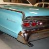
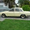
I thought I was the only clown in NZ with a liking for the Sierra Estates Mines a Mk2 Sierra 2.8 4x4 Ghia Estate.
4 points
-
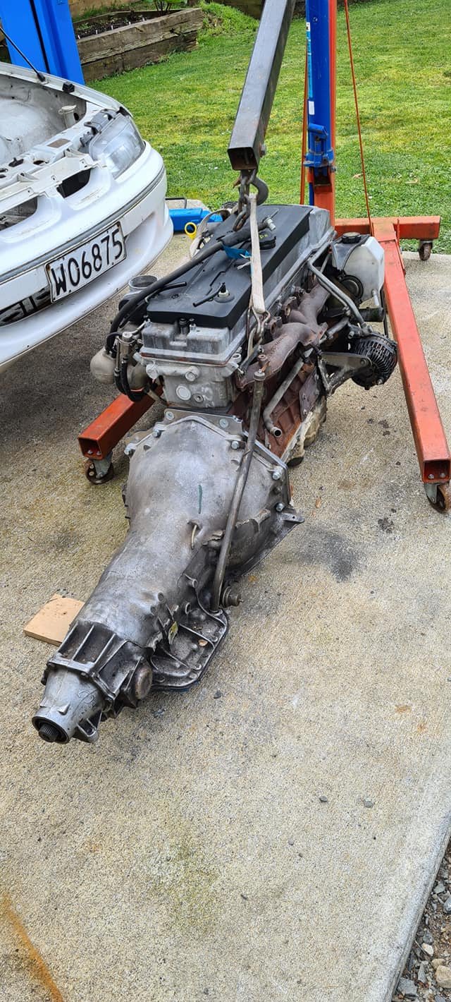
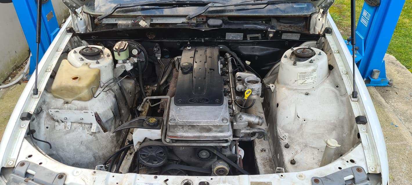
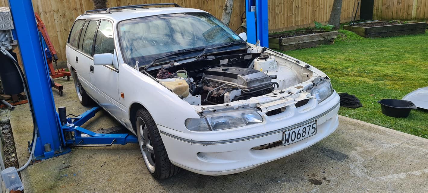
ye sorry but the main reason i got the wagon was so that the gearbox can slide on into a customers project car,you can always keep your eye out for an mt75 box it may or may not fit the hole they came in transits so shouldnt be hard to find. so the blue wagon was 2.0 manual and 5 speed and as i said to ev i cut the plug of the loom for the distributor. my suggestion would be duratech the cunt and put a 6 speed mazda box behind it link and throttle bodies and nice headers and widened steels lowered and drift the bollix out of it.3 points
-
3 points
-
Finally had a bit of time to work on this thing got the Castlemaine rod shop adaptor kit bolted up and mated the TH400 to the engine and got it slotted in the hole Decided to drop the money on the tuffmount barra conversion kit so that will be on the way here soon, tracked down a manual steering rack to pickup after lockdown to give me clearance for a 3.5" dump pipe. still lots to do but looks like progress
3 points
-
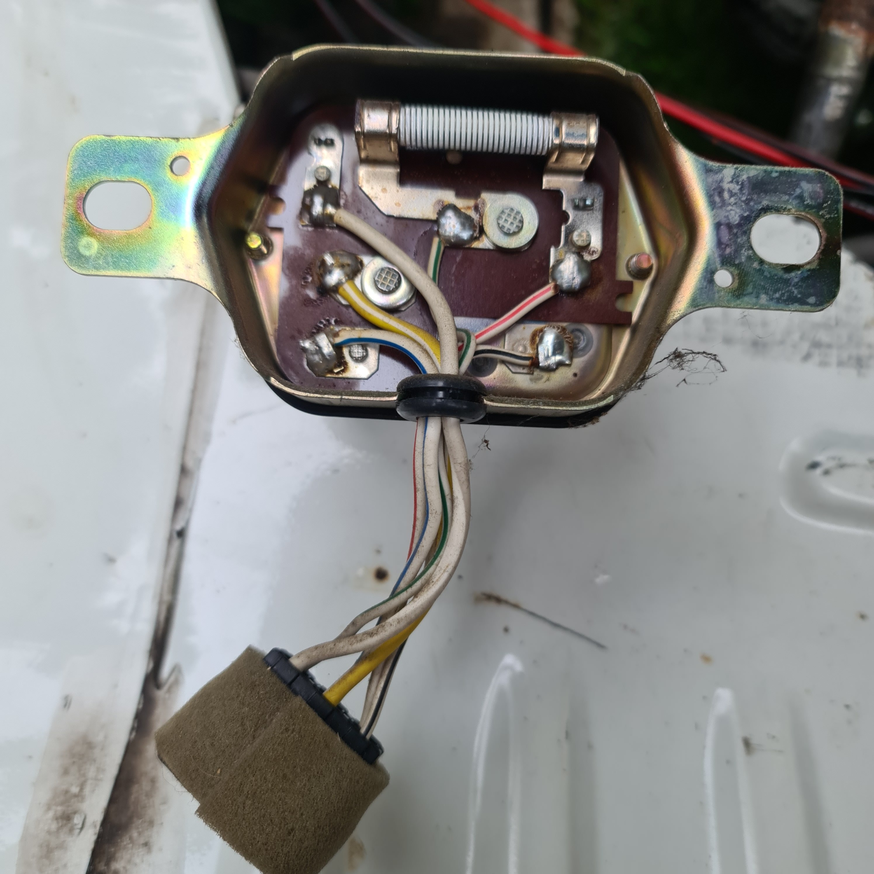
Lowered the front yesterday Waiting on 2" blocks for the rear to level it out. Found the voltage regulator way up by the wipers yesterday so need to figure out how to make a bypass loom in place of it
3 points
-
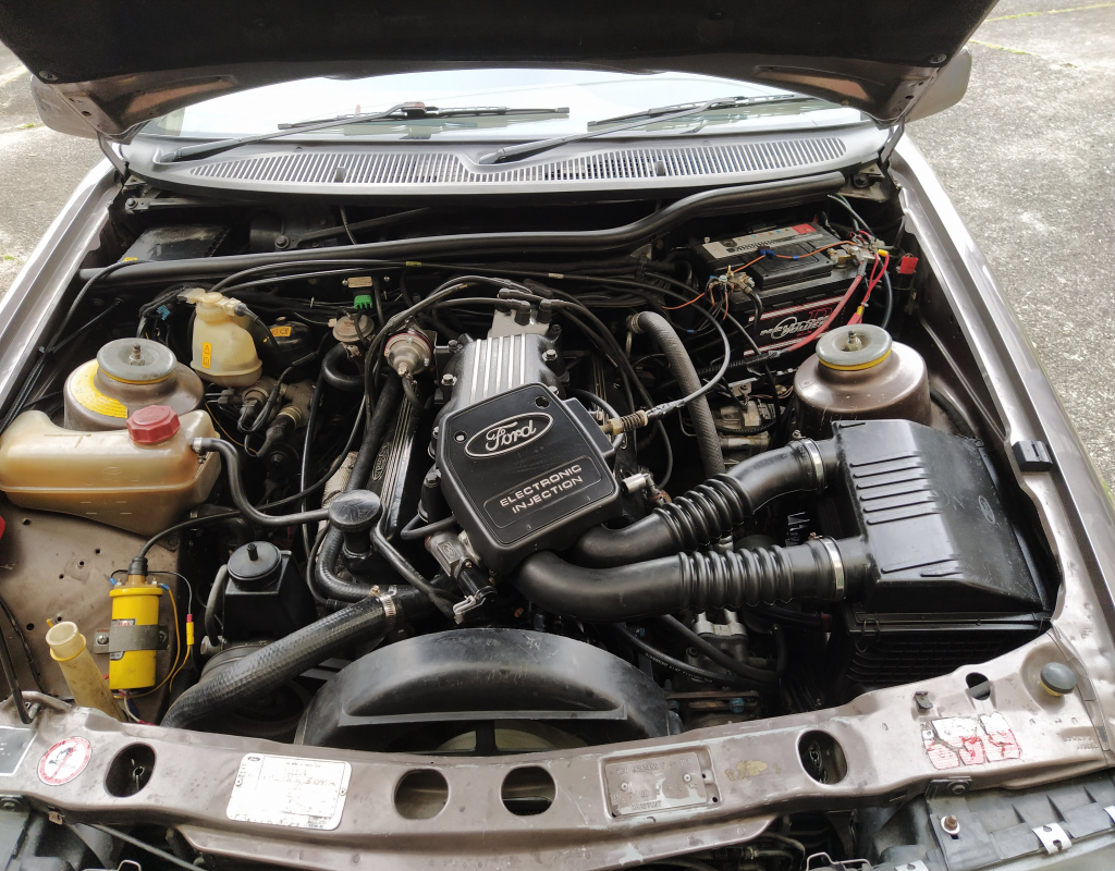
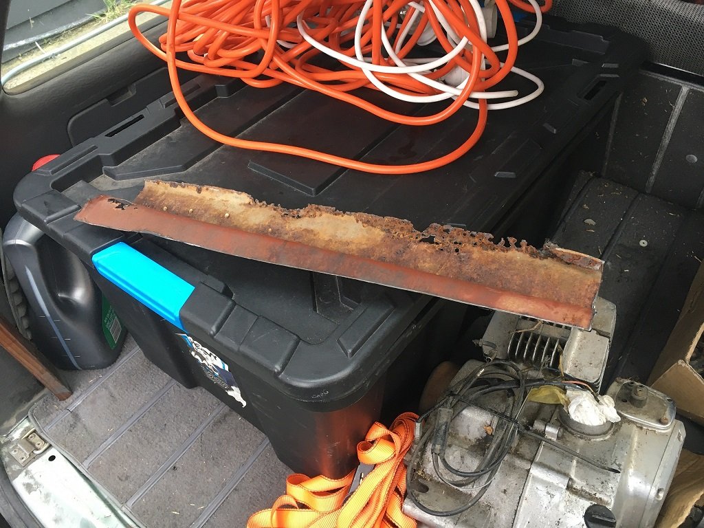
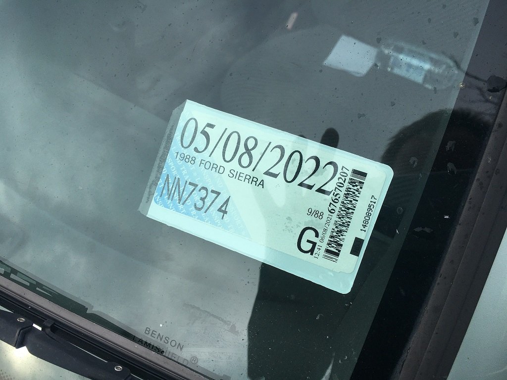
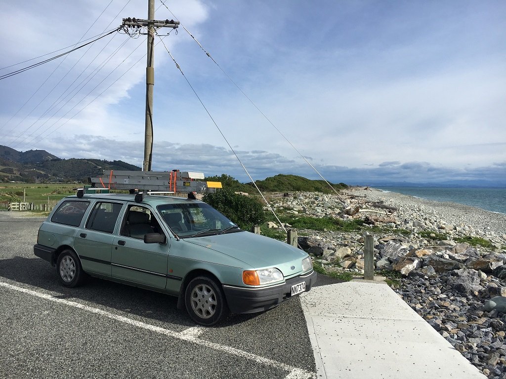
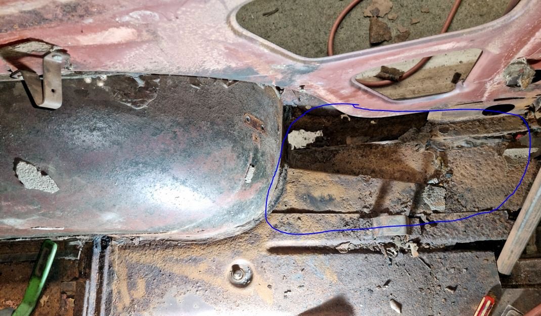
Thanks to James out in Amberly (not sure of his business name, I'll let @- i5oogt - fill in that blank), the naughty rust patch found by that nasty warrant man was cut out and patched. A Quick visit to Kaiapoi Alignment and Tyres for some new rear rubbers, a fresh bulb and a hell of a lot of hope......turned into this. And not a moment too soon as there was pressing work to be done at the islands northern extremities. Grabbed an eye wateringly expensive roof rack (could have shopped around via mail order, but in a hurry) and set off. 3 days and 1400k's later we are back home. It wasnt all plain sailing, steep hills are quite clearly her nemesis and she has an auto choke issue (we think) that means the mornings can be a bit embarrassing (like on the Blenheim BP forecourt). No one really needs to see an older car being pushed away from the pumps so it can have a few moments in the corner having a damn good think about what its done. 15 minutes later, liberal applications of throttle and excessive cranking and shes away again while laying down a blue smokescreen. Weird, cos then its fine for the rest of the day. And starts first time fine, its just the second start after a short run. The run home in the dark was interesting especially when you realise the car behind you is illuminating more of the road in front of you than your own puny headlights. Oh, and the WoF note that the front shocks may need replacing soon was pretty much on the money as steering at speed could be a tad sketchy at times. And with all good wagons, if the back wasnt full on the way home then it was a wasted trip... Great to meet Dylan ( @ThePog ) and a big thanks to the Marahau Mafia ( @yoeddynz, Hannah and Kevin) for their awesome hospitality and discussions on repowering options. Cos as we know, Alex will tell you straight....like a Pear CIder.... (He nearly got gifted a Saaaaab for Xmas but the other 50% owner of the engineering workshop was having nothing of it).
3 points
-
Oh god I forgot about non cross flow haha. Definitely worst case scenario!2 points
-
Other problem is a stinking hot exhaust manifold right under/next to the intake manifold. Without a heat shield. I don't have enough room by the chassis rail to space the exhaust out any further from the head - do phenolic gaskets even cope with exhaust at all? Heat soak with the engine off is almost a problem with my setup, I aim for idle to be 13.5ish:1 under normal conditions as if the engine is sitting for like 15 minutes and then turned back on it will idle at like 15:1 (it idles reasonably well up to about 15.5:1) for a few minutes or you drive a hundred metres or so to pull the heat back out of the manifold. This is even with the CLT correction factors, so it's probably a mixture of injector/fuel heat soak and the possibility that the hot exhaust causes the intake to be hotter than CLT.2 points
-
I guess whats your end goal with it @EpochNZ a pinto with a 32/36 webber and a 5 speed will be a good drivable motor that will last and not cost the earth. Im sure that @- i5oogt - can assit with sortinh a set of headers and a decent carb for it to liven it up a bit2 points
-
Braps over kids.2 points
-
Depends, do you ever want to drive it, or it to be a forever project?2 points
-
2 points
-
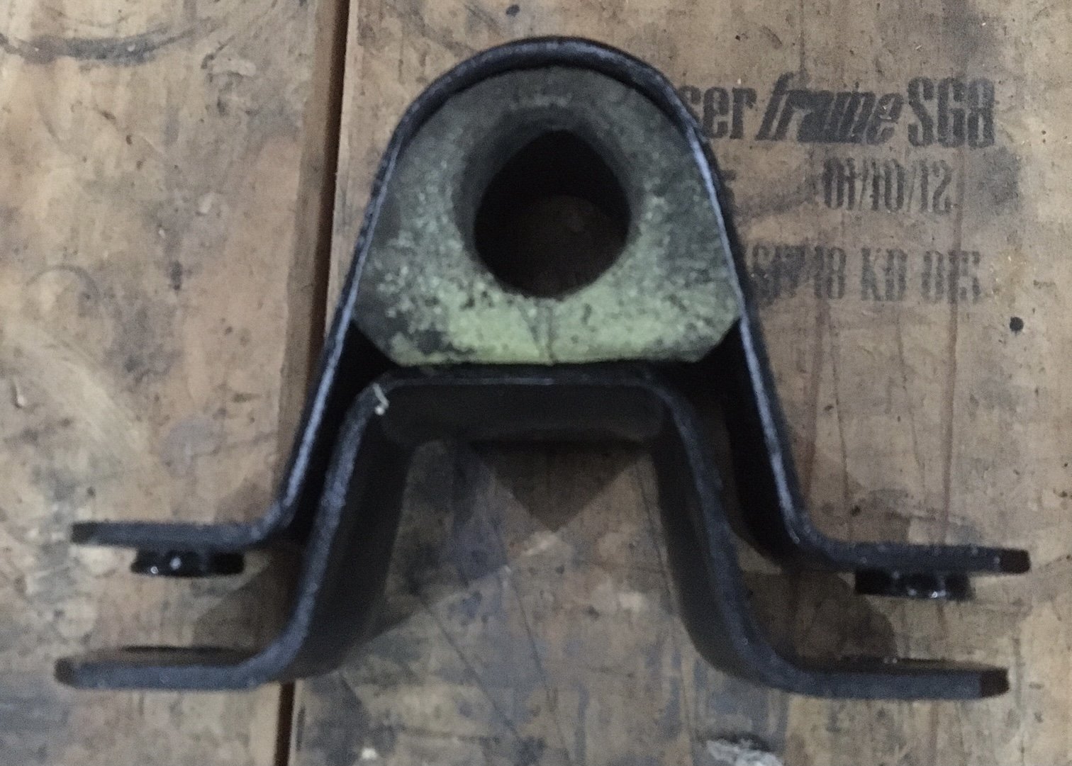
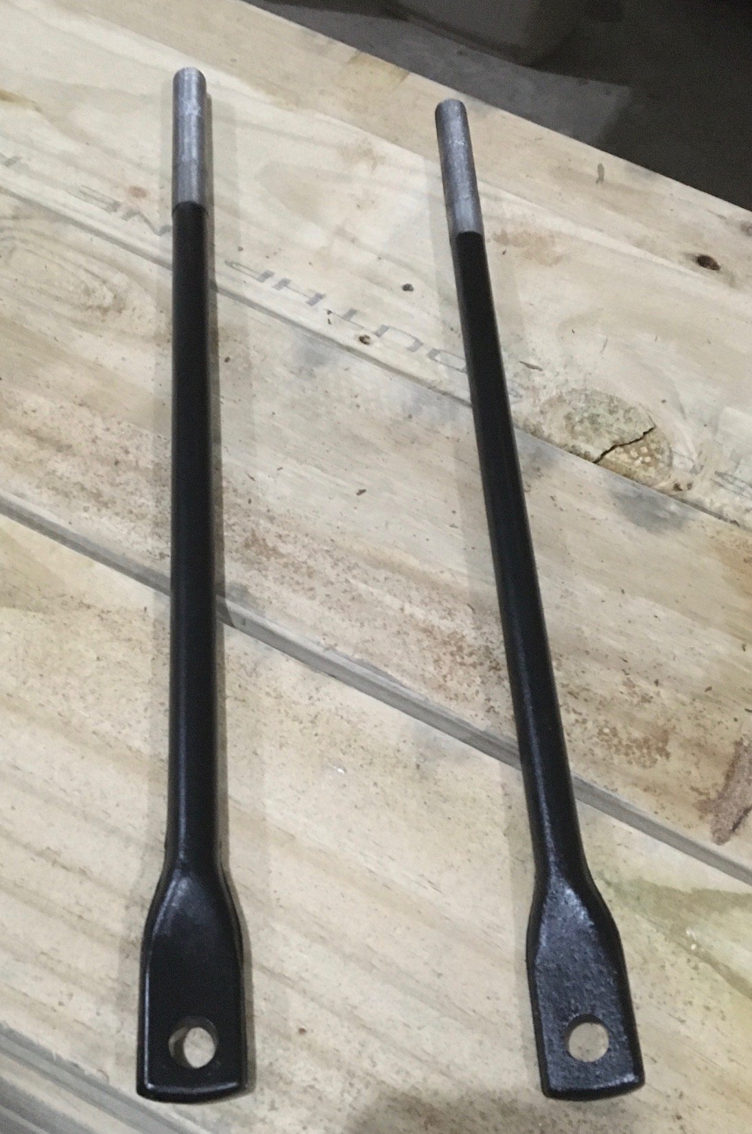
I took a break from the landscaping chores (lockdown =no decking timber) and the wood splitting (drizzle and cold = no thanks) and set to continuing with some front suspension (in)action. All round good citizen @azzurro dropped by recently on his way home from Auckland to give me some rusted junk treasure from his hoard. A couple of (chuckle) thrust rods - as the book calls them. One was straight with a nick in the thread, the other had decent thread but was a bit bent. I chose the latter. One fat bloke and sturdy vice later it’s more or less straight and then into the blast cabinet, prime and paint. Bet you can’t tell which is the good original and which was the bent rusty one. I’m annoyed at my new swaybar bushes now. The new ones are taller than the old ones and no amount of crushing and cursing will make them fit in the brackets. They assemble like so: When installed, the metal brackets are sandwiched tight. Look at the difference between old and new, allowing for oldness and squashedness: I think I might have to cut most of the chamfered raised portion off. Anyway, I’m grumpy now and I’m going to light the fire and have a Sunbeam’s famous turbocharged hot chocolate. Good evening.
2 points
-
Yes. Not quite sure why the tortoise has it. Given his predilection for shitters.2 points
-
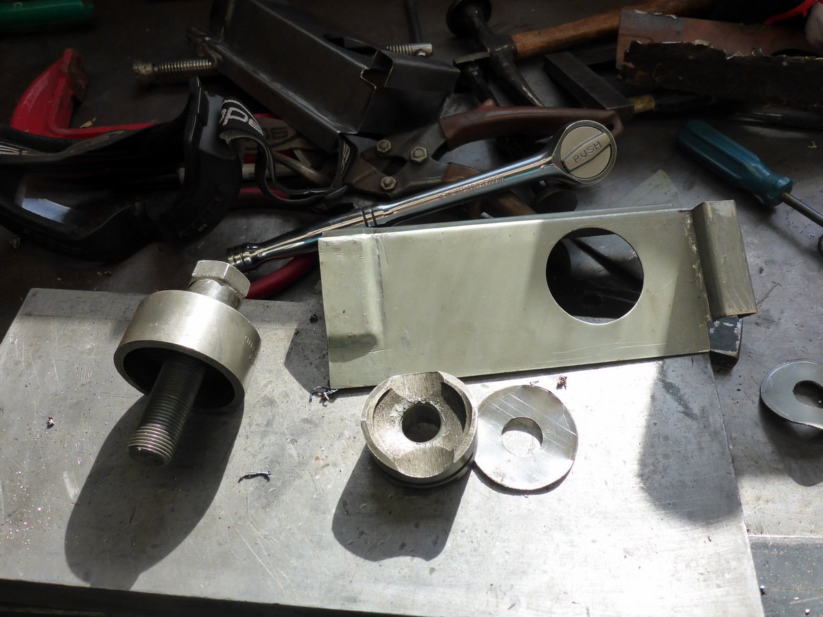
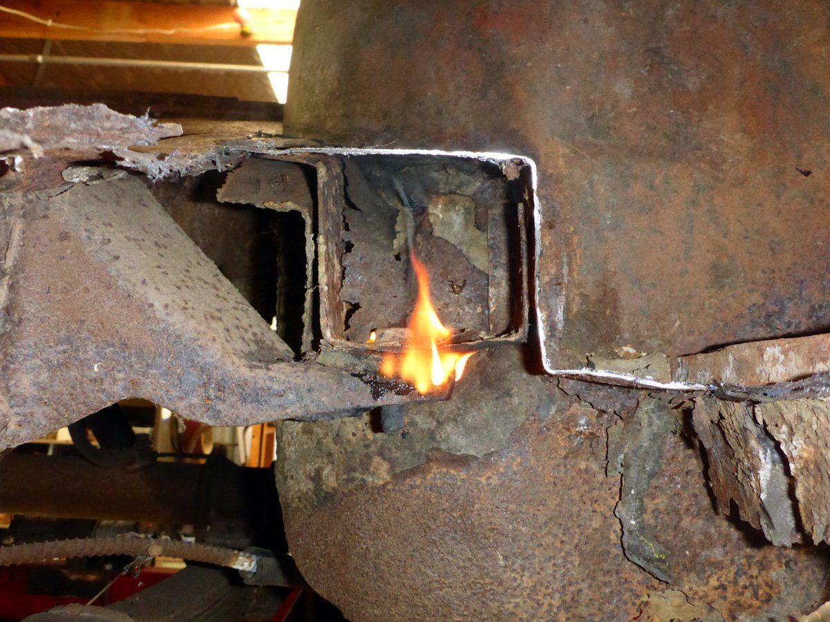
Made some holes in the reinforcing plates. These punches do a nice job. And did some more cutting. First to go is this bit of the floor and the remainder of the inner sill. Body mount bolt put up a bit of a fight but some heat and the impact gun got it off OK.
2 points
-
So the battery went flat as I was wombling about installing the central locking. No prob, I'll give it a charge but it took ages, so shouted myself a new one, thinking the 12 yr old one had done ok... But it started cranking slowly, and let me down once in town, requiring an embarrassing jumpstart. Testing showed low volts when running so I ordered a new alternator... Of course just after ordering it I thought I'd check the regulator, gave it a tap and volts shot up, but no harm in getting rid of the antiquated Ford external reg system. Before I started work I gave it a run with my Ali bluetooth battery monitor. Driving straight after a full charge with the lights on gave 11.68V, and cranking volts were around 9.8V. So out with the old, shame as I'd reconditioned it, is original, and am pretty sure it's working, but they were only ever 40A... And in with the new, a Bosch 70A, and it was a straight swap (luckily, as cost close to $400, came from Aus)... But how to wire it in? Wiring diagram with alternator was no help and the Ford diagram was confusing, till I realised they work on a balance system, with volts on both sides of the lamp, so when it's charging there's no potential difference and the lamp goes out. Was simpler to utilise one of the existing wires from alternator to regulator (connected to D+ on new alt.) and just short the ignition wire to the stator wire at the regulator plug for a test run... Great success, lamp comes on with key, then off as the engine starts, and look... Cranking voltage was over 11V too. Rapt with that, also started much easier, and ran far smoother, didn't need to warm it up near as much before driving off. Guess the electronic ignition needs a good voltage to operate. Really pleased with the battery monitor too, love seeing the status of things like that without wiring in extra gauges etc. I'll connect those wires properly and leave the old regulator in place for looks. Should prob get another WOF now in prep for sunny day cruising...2 points
-
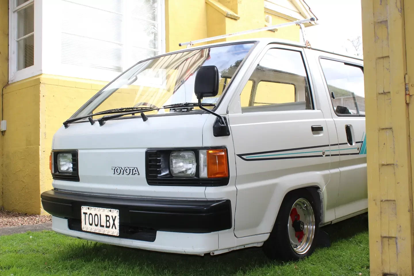
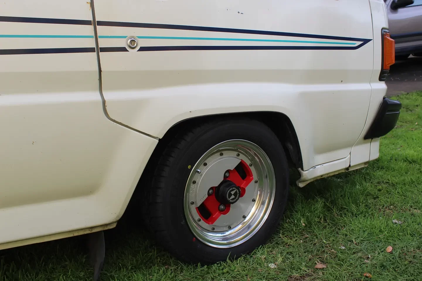
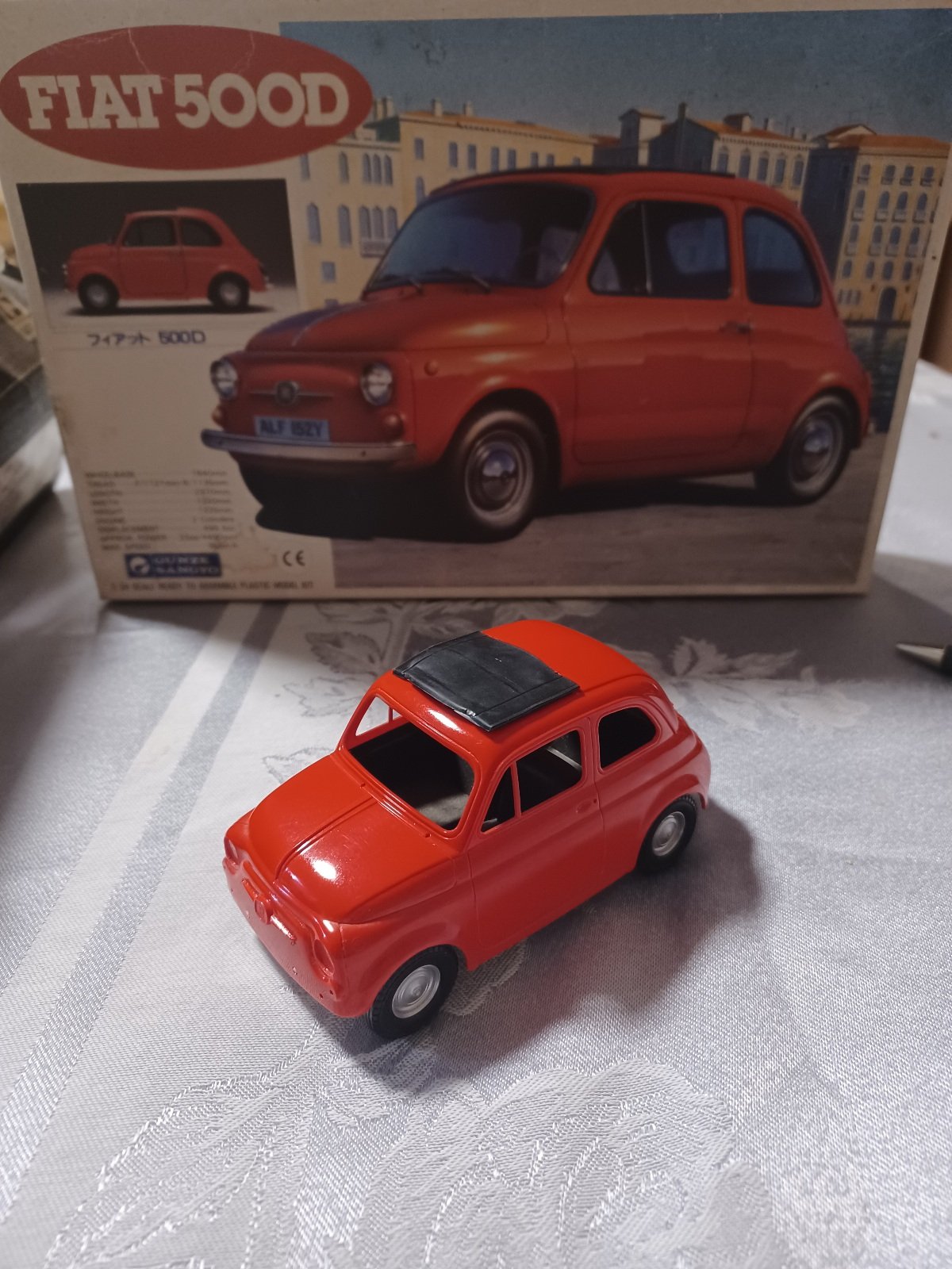
Little covid project
2 points
-
Nice work. I've given this problem a lot of thought in the past. OEM use IAT and MAP in this way, (or used to...) but then they closed loop trim everything and dont give any shits. Then later on when it actually mattered for sake of emissions they use MAF and thermally insulated manifolds. This is a situation where you're dancing around the fact that you're missing a relevant chunk of information which is easily solved with an extra sensor. Which is a thermistor stuck to the surface of the inlet manifold. Probably ideally near the plenum end of a runner or in the plenum itself. OEM doesnt want to do this, because 1x sensor that they can live without saves them $$$$$ across 10 million cars. They have to have an oxy sensor anyway, so just treat it as a problem solved by closed loop. Adding a sensor is the only real way you can account for manifold temp varying while those other values stay the same. The manifold temperature is a result of temperature in (from the head) and temperature out (carried away by airflow) If you do a constant run at full throttle you'll slowly cool the manifold even though all of your measurable conditions stay stable. If you do a constant 100rpm low load on the motorway, you'll slowly heat it. If you dont have any way of accounting for this change over time, then you havent solved the problem. But if you've built an IAT/ECT compensation table that gets it ballpark most of the way there, and stops hunting idle etc then thats awesome! Good work. You could also look at thermally isolating the manifold from the head. Another issue is that you can get variations from fuel temperature soak as well, when the fuel rail heat soaks and there's a low fuel volume in the tank, and a hot road reflecting heat back up at your gas tank. Streeter Industries in Oamaru can cut phenolic gaskets if you give them a sample.1 point
-
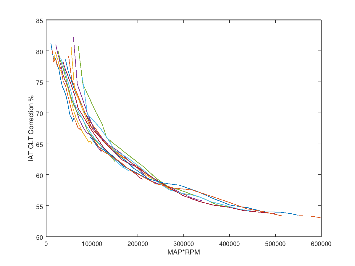
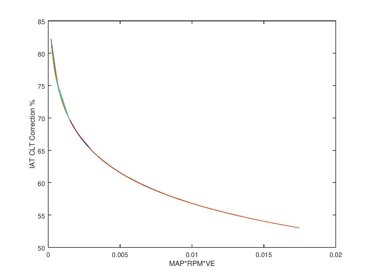
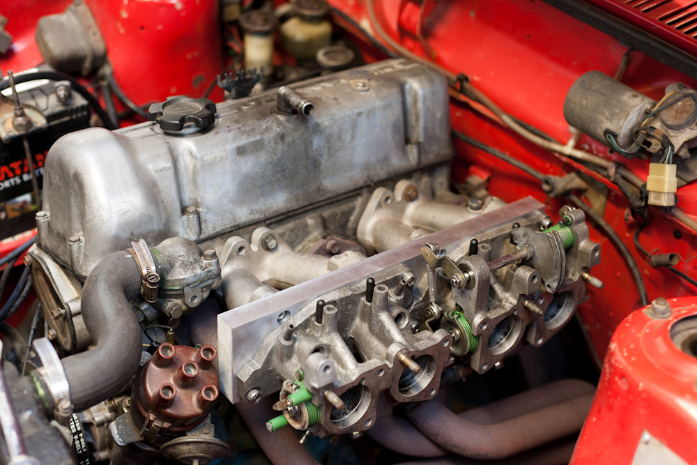
Due to the location of my IAT (airbox) sensor on my setup I have always had a little bit of difficulty determining the actual temperature of the air when it gets to the cylinder. The engine has long steel intake runners that heat up over time, affecting the heat transfer. I could theoretically rip the manifold out and weld a bung on to put the sensor right near the head but this would not look quite as per how Toyota would have done it, and Toyota made millions of cars with air temperature sensors in the airbox anyway so it's theoretically possible to make it work well. Symptoms of incorrect air temperature prediction are leaning out as the IAT increases when idling, AFR changing as the engine is heating up to steady state, AFR bouncing all over the place at certain RPM/load conditions etc. A fix for these issues is to use an IAT/CLT correction factor that blends to two values as a function of air flow rate to predict the actual temperature. The most common approach is to set the correction factor to near 100% at idle conditions and then the rest is just determined through trial and error and just forgotten about when it's determined to be good enough at steady state. One problem with this setup is that the model uses RPM*LOAD to predict airflow and doesn't care about VE at all, which causes large errors at low load conditions where VE can be less than 50%. I don't believe that this can easily be tuned out. Anywho, what I recently did was pulled out my old thermodynamics book and opened the section on convection heat transfer into fluids flowing in a pipe. I used GNU Octave to develop a simple model of the intake system and engine and generated a surface map of predicted correction factors for all points in the engine tune map. I can adjust intake runner diameter, runner length, engine capacity, runner temperature profiles etc. The model uses the VE table from TunerStudio to calculate actual mass flow rate at each point (technically this model will cause the VE table to change, so some iteration may be required for more improved results). A collapsed output from the model is shown below, giving the expected shape of the curve for my particular engine (I still need to actually measure the temperature of the runners at various points to confirm). I've put the predicted curve into TunerStudio and the engine no longer hunts when you sit there holding the engine at around 1500 rpm with no/low loads and the AFR seems to stay constant for a wide range of IATs now. I don't know what can really be done to fix the AFRs being somewhat all over the place (ie being 14:1 when the engine first gets to 85C but slowly changing to 14.7:1 as the runners heat up, with constant IAT) as the engine is warming up to steady state apart from adjusting the warmup enrichment curves. We see the limitations of the megasquirt correction factor when we compare the results of the MAP*RPM model vs if we include VE (x axis is mass flow rate, kg/s - below). At low load conditions there is a broad range of correction values for each MAP*RPM condition, which results in a large uncertainty of what the actual correction should be. Perhaps I should look into playing with a MAF sensor one day, but there isn't really any room left for me to fit one in the engine bay without making it look out of place. Side effect of the model is the prediction that if I cut the length of my runners from 650 mm to 250 mm I could increase my power by 6% by dropping the temperature of the air getting into the engine from 57C to 38C at the upper RPM range. That could be a good excuse to make a dual runner system with a butterfly valve that swaps them at a certain RPM in the future.
1 point
-
Is the blue shell manual or auto? Getting a manual box to go behind the pinto motor may be the most expensive part of the exercise1 point
-
Yeah just swap over drivetrain over and enjoy now1 point
-
wanting manual? Try and find a complete one of these? https://www.trademe.co.nz/a/motors/car-parts-accessories/ford/engines/listing/32320274291 point
-
It would be a bit weak in a bike but should be pretty fun in this and it looks sweet! engine mounts are made i just need box section to finish it up where the rear mount will go. Ive got some mikunis off a kawasaki that would be perfect if its too asthmatic. This is for my daughter shes 14 and just recently got her head around riding a dirtbike.1 point
-
Buy standard mirror (non-toughened) and waterjet cut to shape. I have used our waterjet to cut glass of all sizes so don't see why this wouldn't work.1 point
-
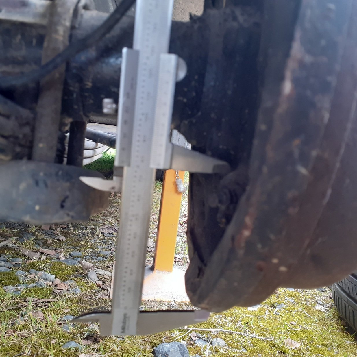
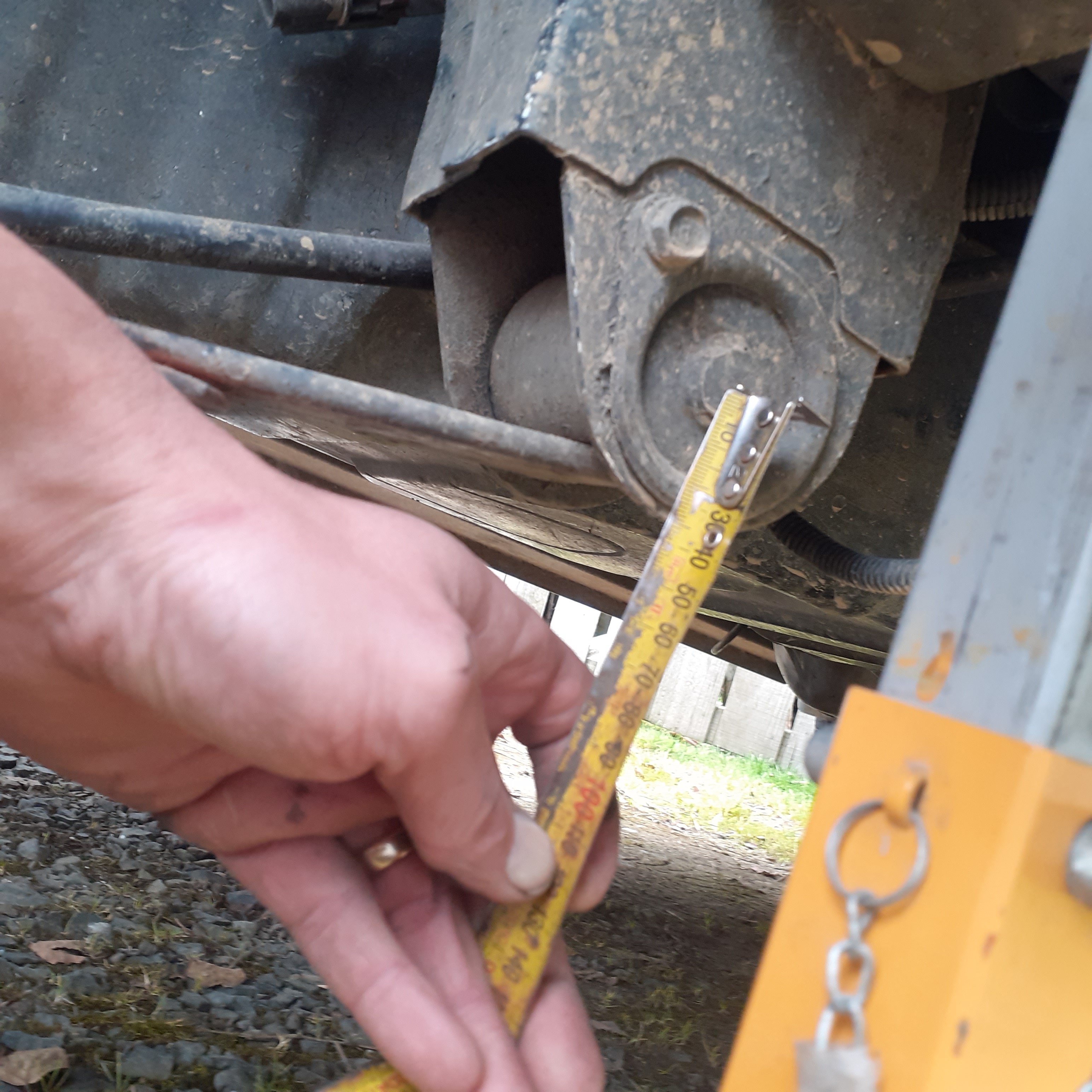
After a LOT of measuring of the car at rest, a copy of caltrac bracket measurements that someone put online, and limiting factors such as the lowest point on the drums which i was going for, though it could probably be lowered to the edge of the rim ,so will probably lower middle bracket to that.. but this is v1, should help hold the diff and pinion angle in place and allow movement without any kind of binding problems??i came up with something that might work and all angles and lengths can be pulled from
1 point
-
Hood frame got a big wire-wheeling and epoxy etched + a couple of days to cure. Soon I’ll fill the wee pinholes, clean the scoops and put back together Headlight time. Sand blaster has been running hot for days! Anything metal gets a blast Otherwise just a clean and polish. Got the NZ dipping style lamp in too. Now to finish the other side.1 point
-
Mo’ bonnet, mo’ ugly couple more hours and I think I’ll phone it in and bury it in epoxy etch and spot the skin back on1 point
-
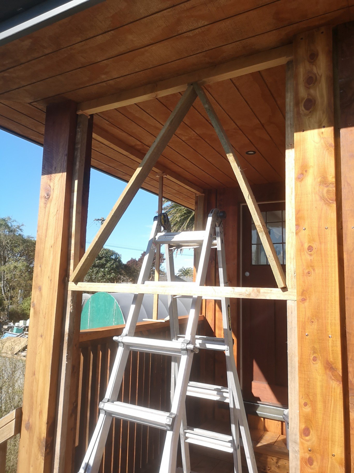
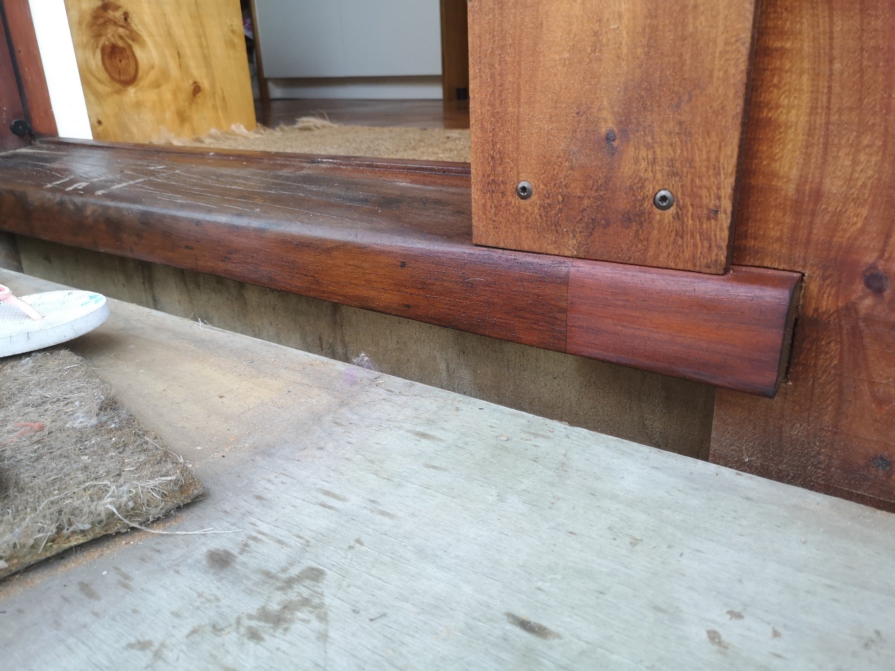
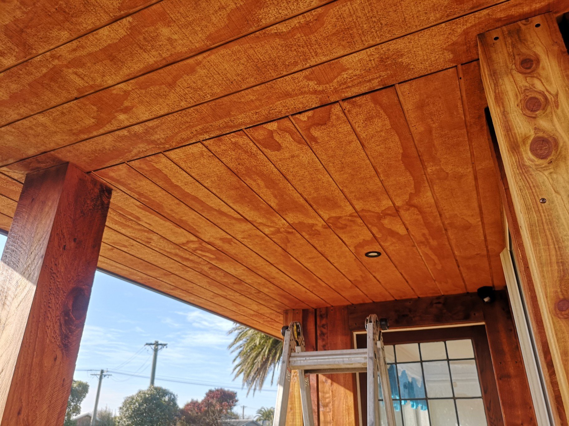
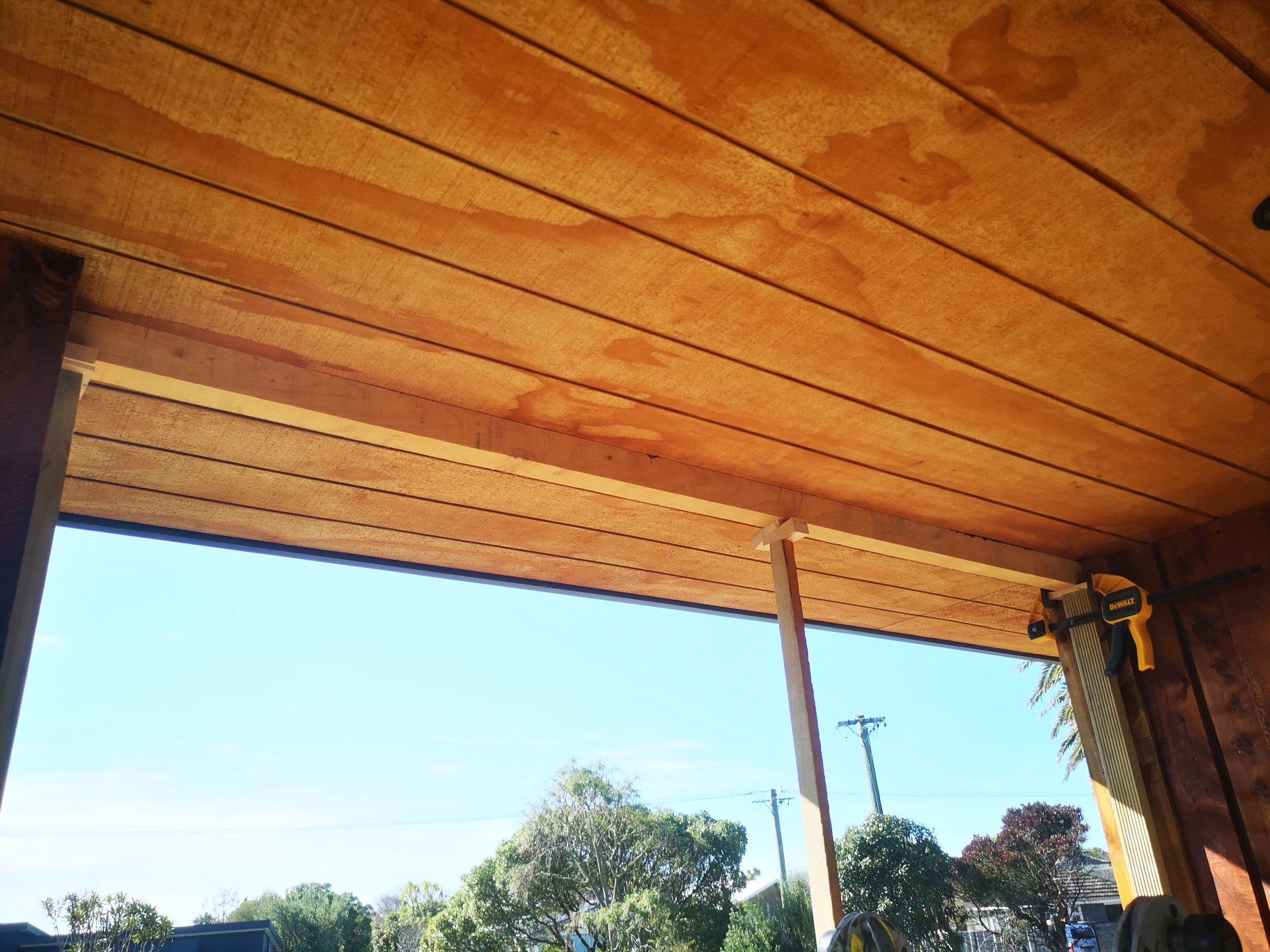
Finished up the threshold, can see the addition but you always would.. Might stain the whole lot a bit darker.. Also put the trims up to hide the soffit joins.. Soffit before, they don't lol bad in the photo but there's some height differences and gap variation.. The photo has a wack bracing setup cos I didn't want to waste any timber on it.. Typical idiot I was getting a wedge out of a bucket by the front door and totally smacked my head on the cross bar knocking the entire lot down on my head.. Knob.. Luckily the trim stayed up glued by the 11fc, my initial thought was I had and I was spewing as once 11fc goes everywhere its a cunt to get off.. Makes exceptionally good glue tho. Tomorrow I'm gonna take all the spare timber down to store at my old lady's place, then make a start on the back deck..
1 point
-
Not the lockdown news I wanted to hear with a week of annual leave left..but here we go. One of the splash/inner guards..underseal straight over bare metal! blasted, rust converted and black zinc. This ugly lump of fuck could have gone back in and been sent, but it would annoy me and I’ve got time on my hands. good to see a new cam and followers too! There been a leak but this thing hasn’t run much, Still assembly lube in places. Hope this doesn’t bite me later, I’ve cleaned it up and will do a few oil changes and filters. someone has port matched it too.1 point
-
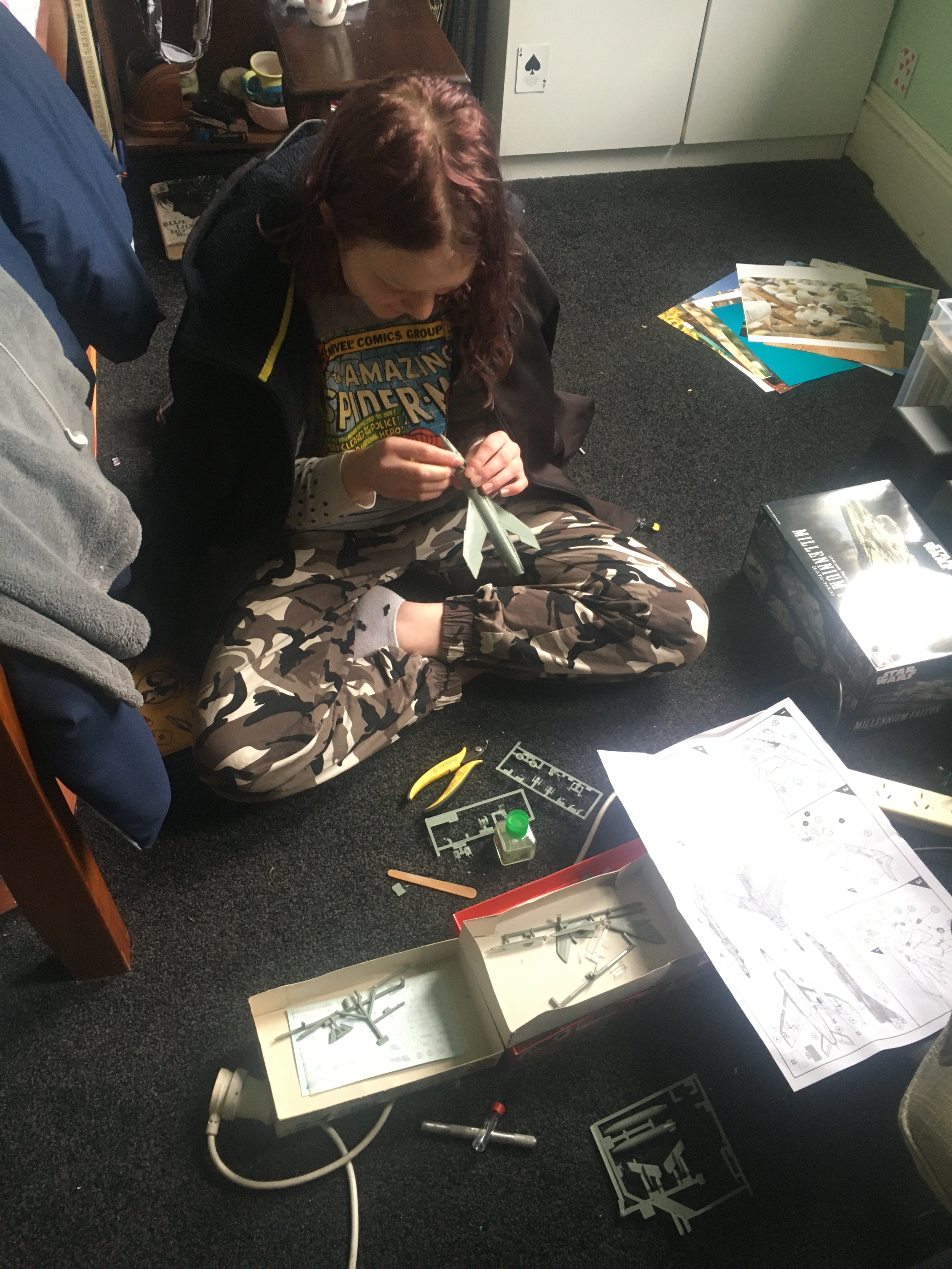
@chasinthemirage She’s just having a go at a warmup kit to get the basics right before attacking the Falcon. (It’s an original tooling Airfix Super Etendard in 1:72 that had been in my stash for years for those following along at home)
1 point
-
Jacked up a corner of the girlfriend's Passat to figure out how to do an oil change and the small windscreen crack turned to a spider's web. Thats when I realised the mechanic can have my $$$, the only thing I will turn on that car is the heater control.1 point
-
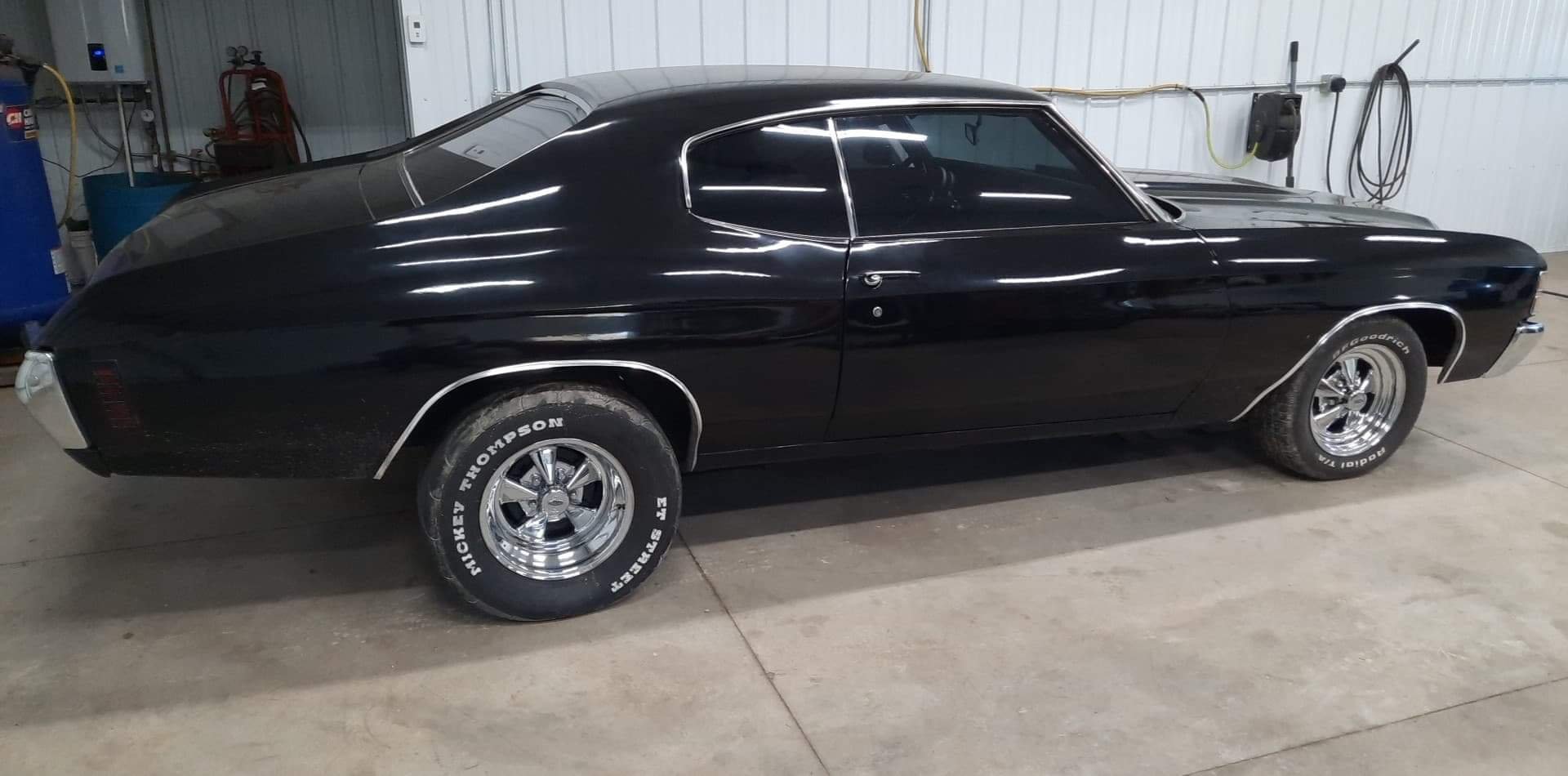
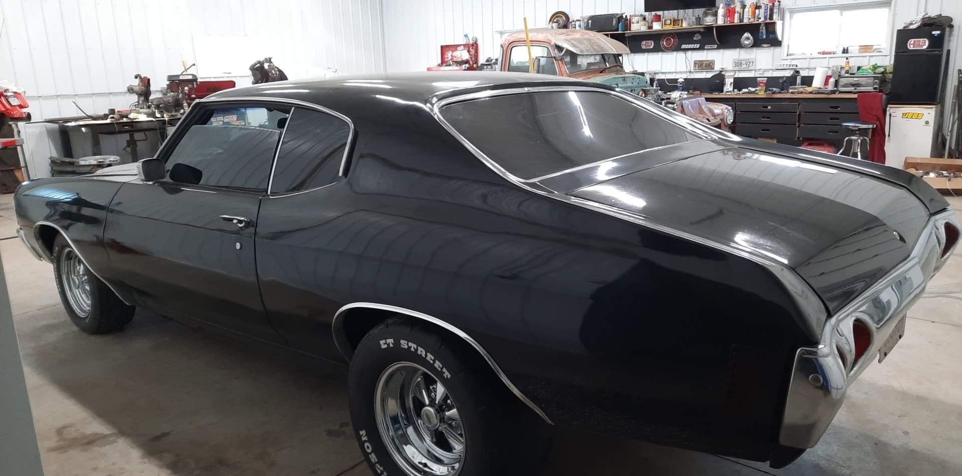
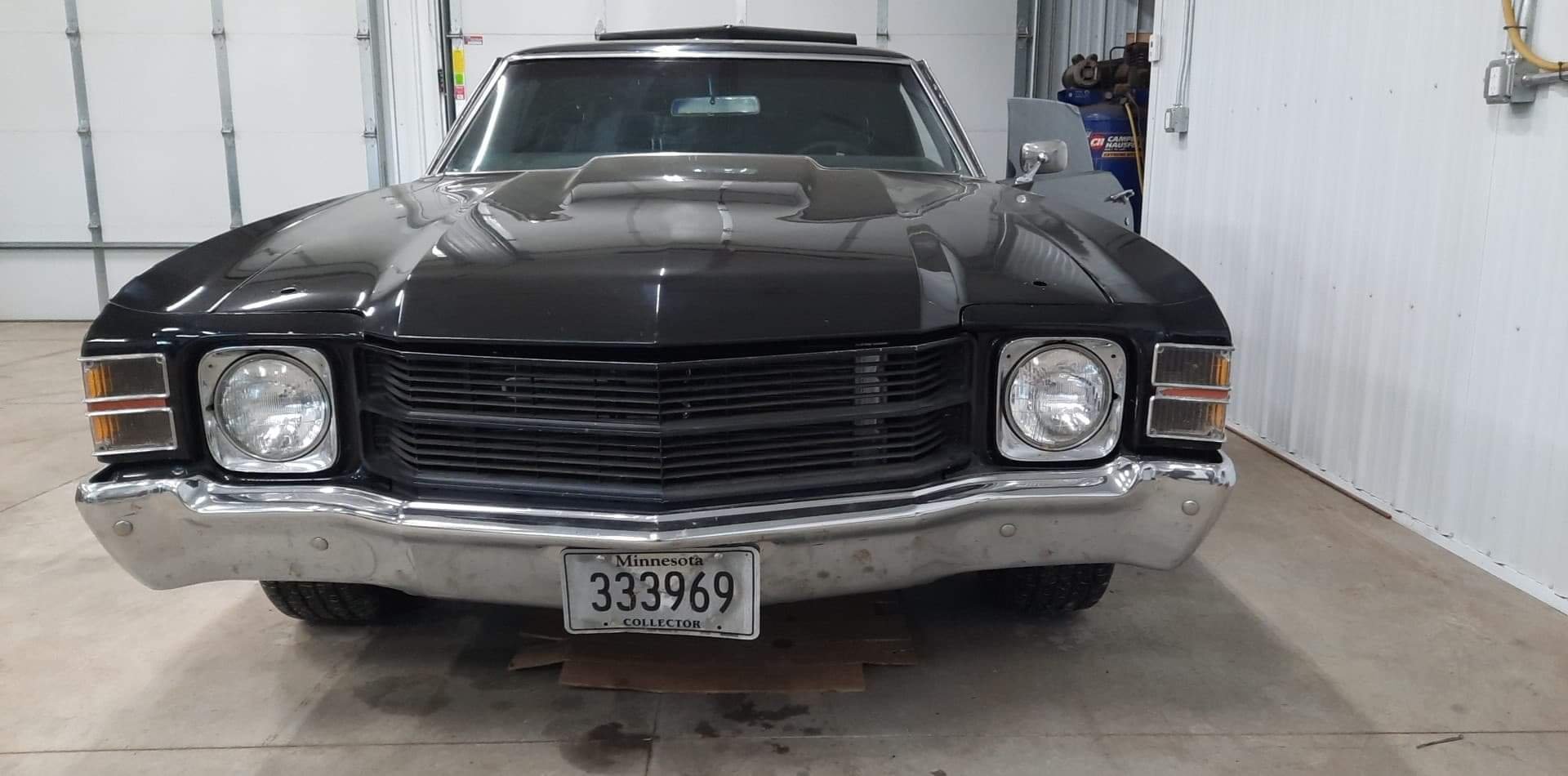
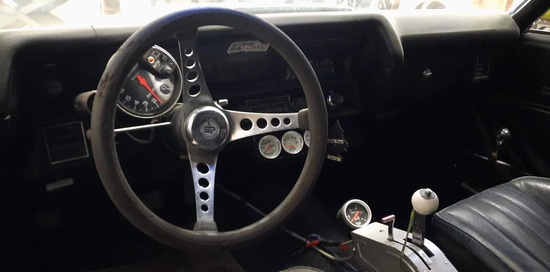
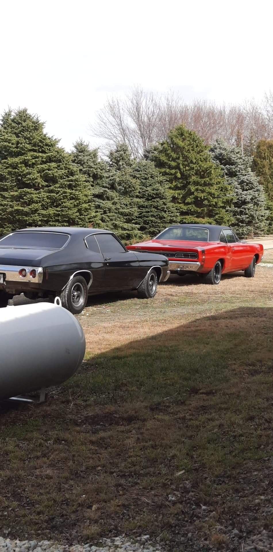
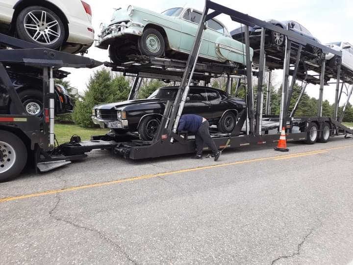
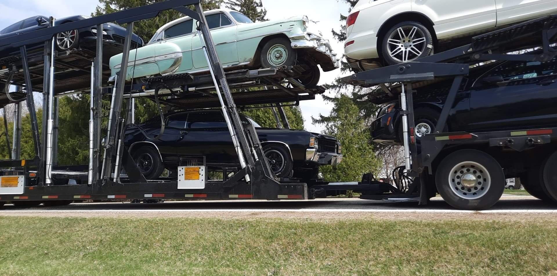
Well for the most part covid sucks. Was meant to go on a 6 week honeymoon - that never happened as I was booked to leave late Feb last year. Lockdown mk1 came around and I got on somewhat of a daily tangent of checking out eBay for my shortlist of muscle cars - came very near to hitting the button on a '70 superbee but it wasn't to be. Fast forward a year and I still hadn't bought anything and had nearly given up all the while saving more. Turns out there's actually bugger all on ebay (even with changing your region to USA) and most cars are on Facebook via various groups. Really wanted a '70 Chevelle - but had to be Big Block and ideally manual. Turns out so does everyone else, which pushed it out of my budget. However the same body is carried through 1971 and 1972 and you can actually buy all the parts brand new for whatever you desire. I came across a tubbed '72 but this had really been molested a but much for my liking. Then another '72 but the seller seemed shifty so gave that a miss also. At the same time as I'd commented on one of the aforementioned '72 in the comments a seller offered what you see here for a very reasonable price. I pm'd him and asked for more details. He was inundated with messages so I put a deposit down. Then rang and spoke to him for about 30min over my lunch break and organized to purchase the car. Some 3 weeks later the car was picked up and transported from Minnesota to LA. Kiwi shipping were great to deal with and provided plenty of photos showing some things that I couldn't see from the seller.
1 point
-
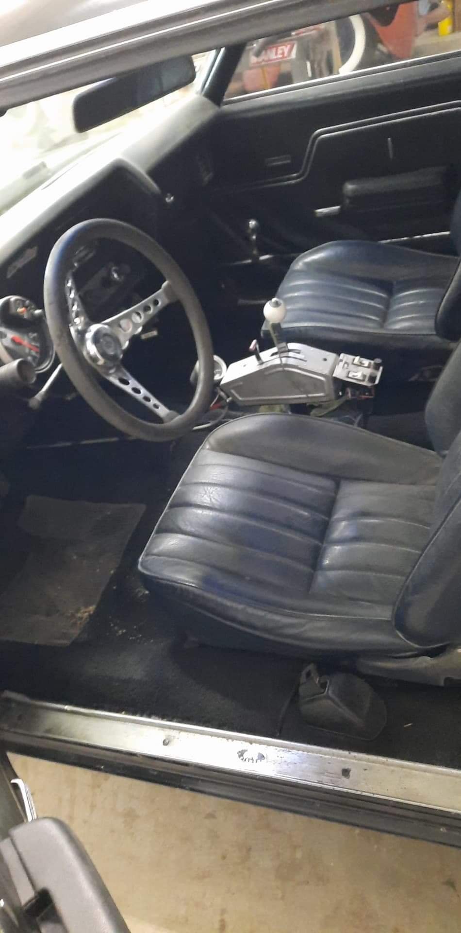
This was followed by a late night weekend mission rifling through my bolts box trying to find gearbox to bellhousing bolts (as everywhere was shut and time of the essence on my day off). Ended up piecing together 4 bolts from my own pile and a friends pile, tapping the bellhousing to tidy the threads & running the die nut down 2 of the bolts that were too long. (Imperial bolts aren't what I have a great deal of) Interesting point I learnt, the SBC and BBC both share the same bolt pattern for bellhousings and clutches.. Installed this in the car lying on the garage floor with my trusty trolley jack and some strops for safety to avoid crushing myself, but came across my first stumbling block - the factory body mounts have sagged too much - my shifter sits too high even with the shortest trans mount. So fitted it up sans trans mount and shifter. Ordered some which turned up the day before the current lockdown, and I promptly left them under my desk #doh Cut the hole in the floor for the floor shifter stamping Tek screwed it on after trimming the floor. - I then used these holes for plug welding Stitched welded the edges. Filled in the holes in the firewall, and in the floor where the seat mounting holes had been punched through..1 point
-
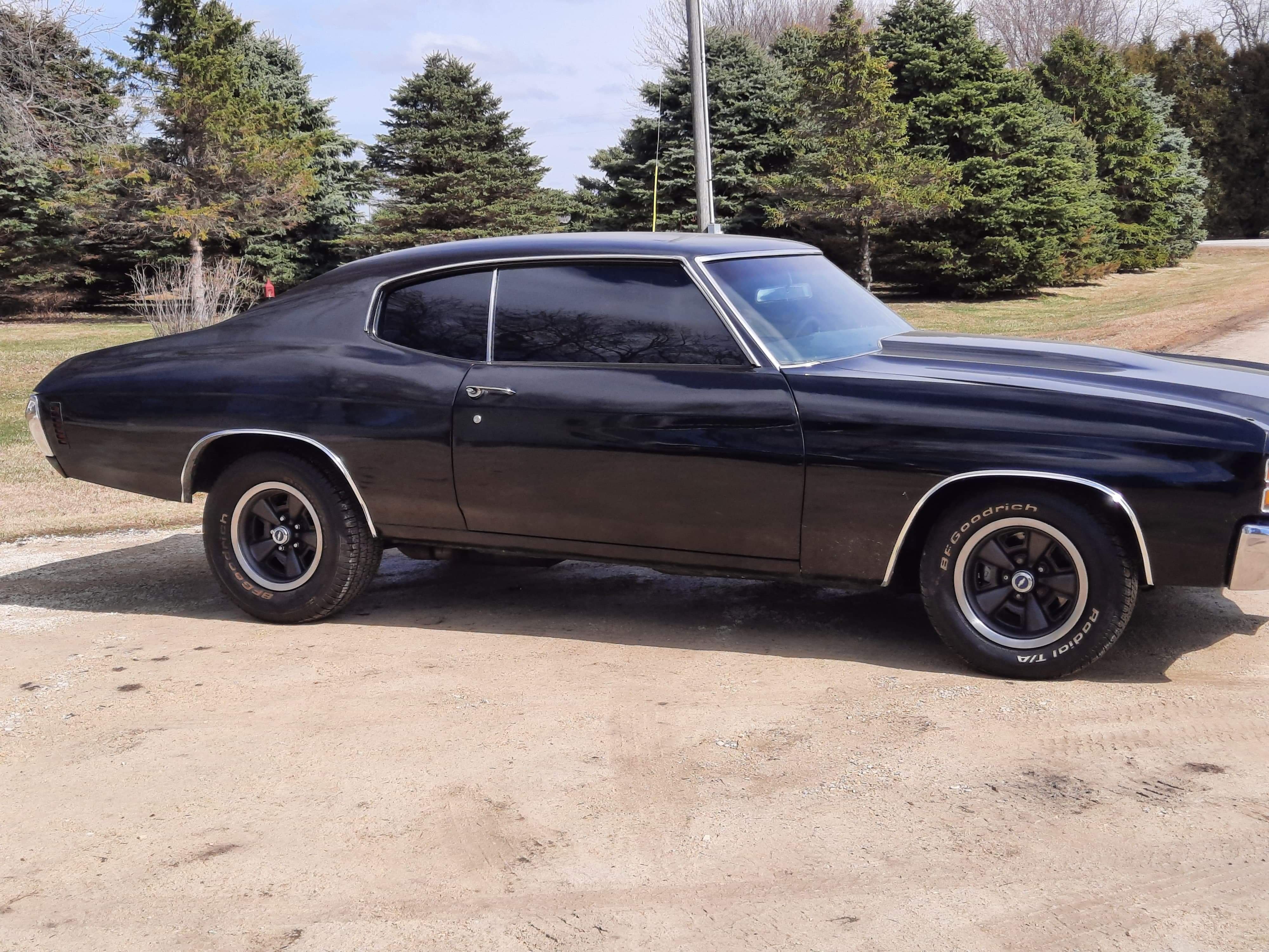
Before the car left I sussed a deal with the seller and found a set of SS wheels 15x7 - he paid for them and kept the current wheels/tyres for his superbee. Also came very near to buying the full 70 sheet metal conversion but decided to cool my jets and wait till the car arrived (as this was my first experience buying overseas) But I did hit the button on quite a few parts I had made a wishlist for as soon as I'd paid the deposit..
1 point
-
I would totally be surprised if it didn't. I removed a panel from the Defender that needed touching up, was so much easier having full access to both sides with nothing in the way. Best to point out that i'm not looking for the shortest path to having the Datsun looking good again, i'm looking for the most enjoyable path where I get to learn stuff. If we can hold religious meetings under L4 you're welcome to visit and read me a sermon from the book of hammers @JustHarry1 point
-
Also, can you unpick the panel to work on it off the car? Would make the job a whole lot easier...1 point
-
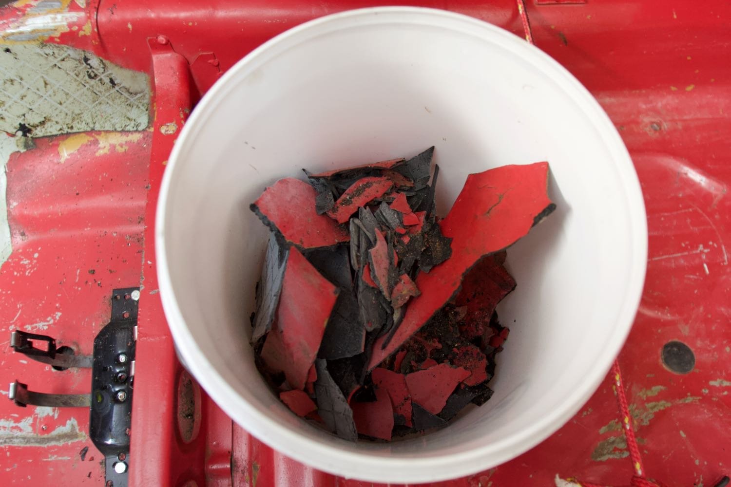
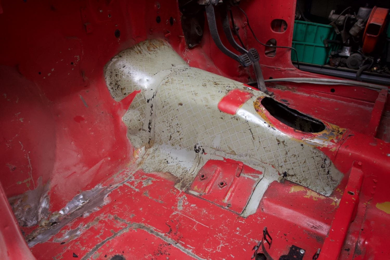
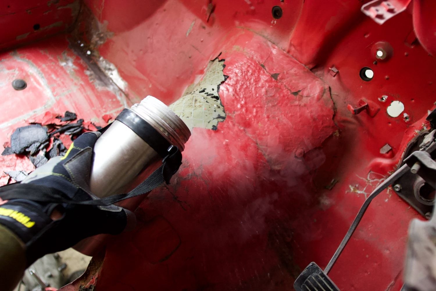
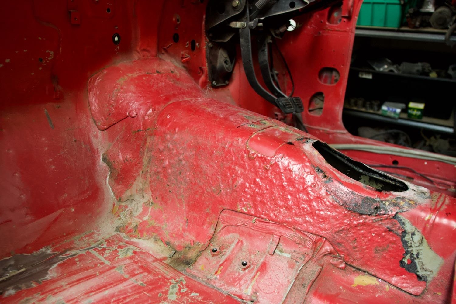
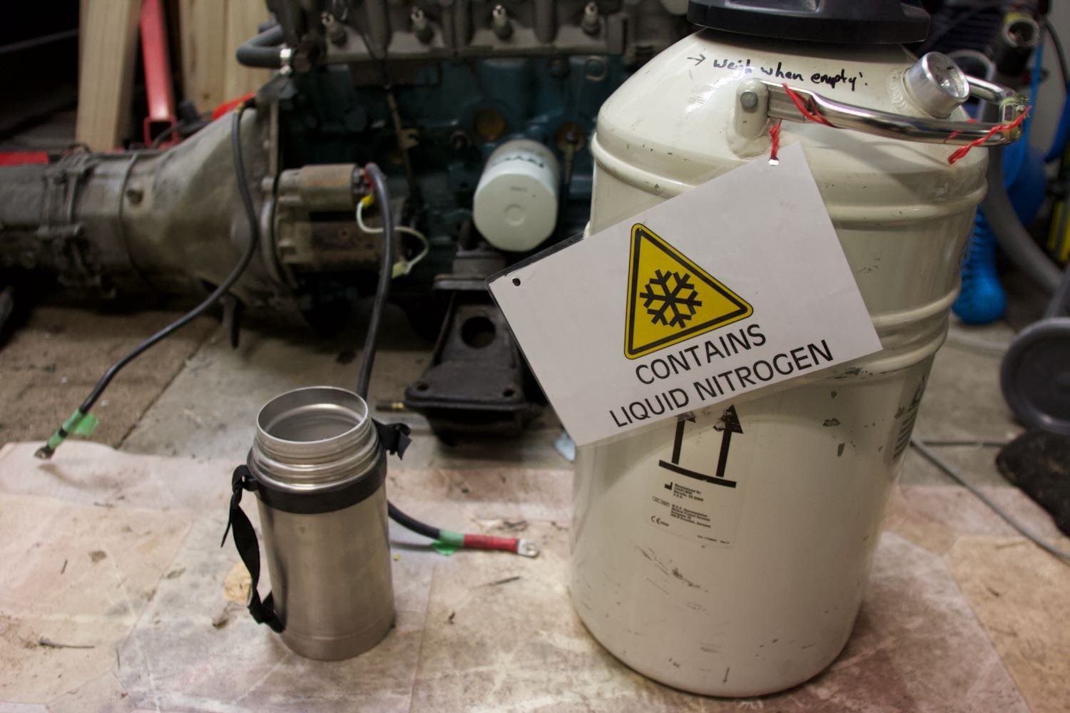
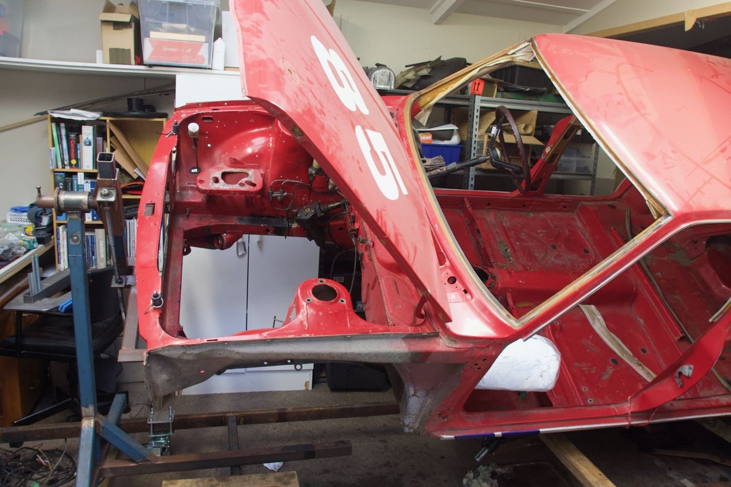
Trucking along..... Shell is now 99% stripped and mounted on the rotisserie. Motor and box were dropped out the bottom during the lift, closely followed by the rear cross member, diff and suspension. I've started stripping paint (and bog) from the known trouble spots to start building a picture of the scale of panel beating, so far nothing that make me uncomfortable, more motivational as the patches are (so far) straight forward chop&weld. Work had a few litres of liquid Nitrogen going spare so rather than pay BOC for dry ice I filled up a tank to see how well it can take to sound deadening. Before: Pouring over small sections at a time I was genuinely surprised at how effective it is, large chucks peeling off in seconds. Soon there was a full bucket and job done I wouldn't hesitate to give that another go, so fast and even strips the seam sealer out without breaking a sweat! Having the car on the rotisserie was an added bonus, could position it so that the liquid would pool in useful places.
1 point
-
I have one of those that I snapped the jaws on. Top quality. Happy to send you whatever other turd part you want from it if it's the same.1 point
-
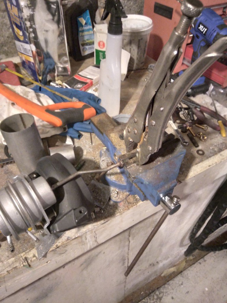
has anyone ever repaired or gotten parts for these cheap vices? turns out this baby is a holdin' vice not a crushin' vice, i stripped the main nut on it. the nut is a barrel and plug thing cast together, I see this type of vice for sale all the time so presumably someone's dealt with this shit before in the meantime yo dawg i heard you like vices, heres some vice grips to grip yo vice while yo vice grips... (seemed to do the trick at least)
1 point
-
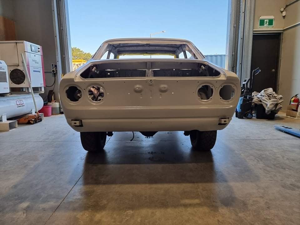
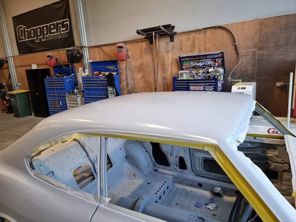
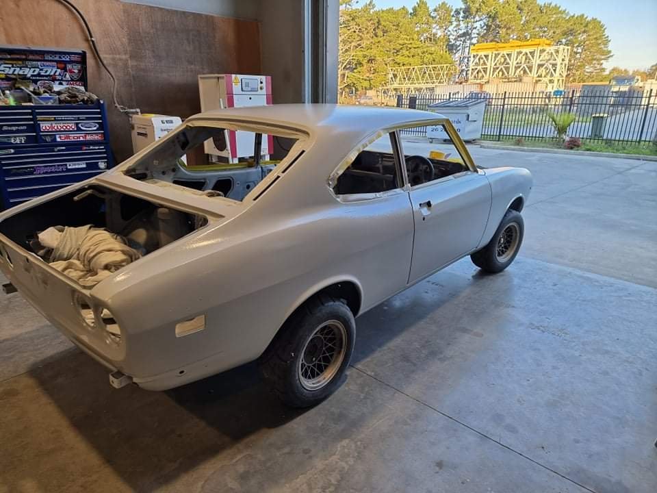
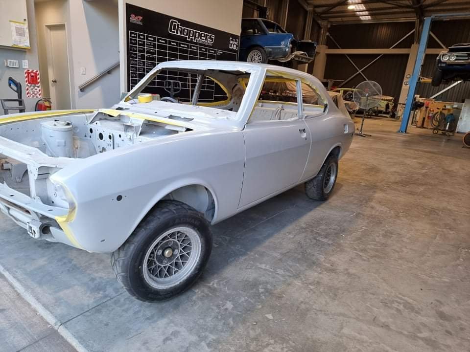
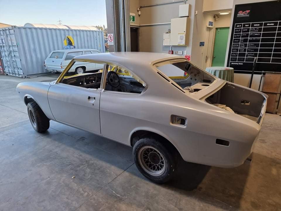
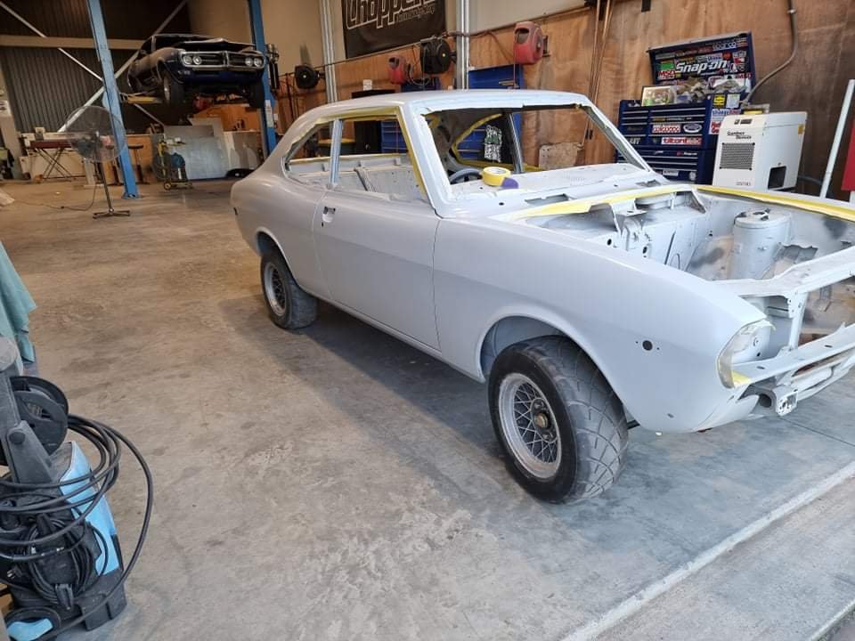
Some filling/blocking priming underway, coming out way better than I imagined
1 point
-
Finally got the throttle body adapter plate port matched and dropped it on the current motor for visual motivation Started a quick spreadsheet and have rapidly worked out I need ~45 individual wires running through the firewall to operate the motor and the usual electrics (lights, wipers etc) most of these are because I wish to move the fusebox and relays into the cabin. A quick estimate and this looks to be about 55m of cable.... For ease, putting a 50pin connector on the bulkhead looks to be the way forward. Rather than threading each wire, I can wire the loom on the workbench, any suggestions for a bulkhead fitting thats not $200 mil-spec?
1 point
-
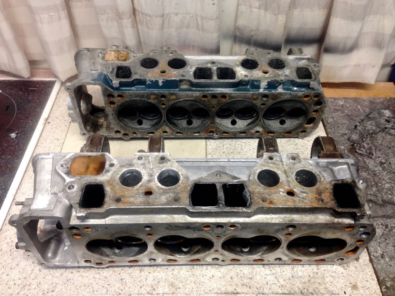
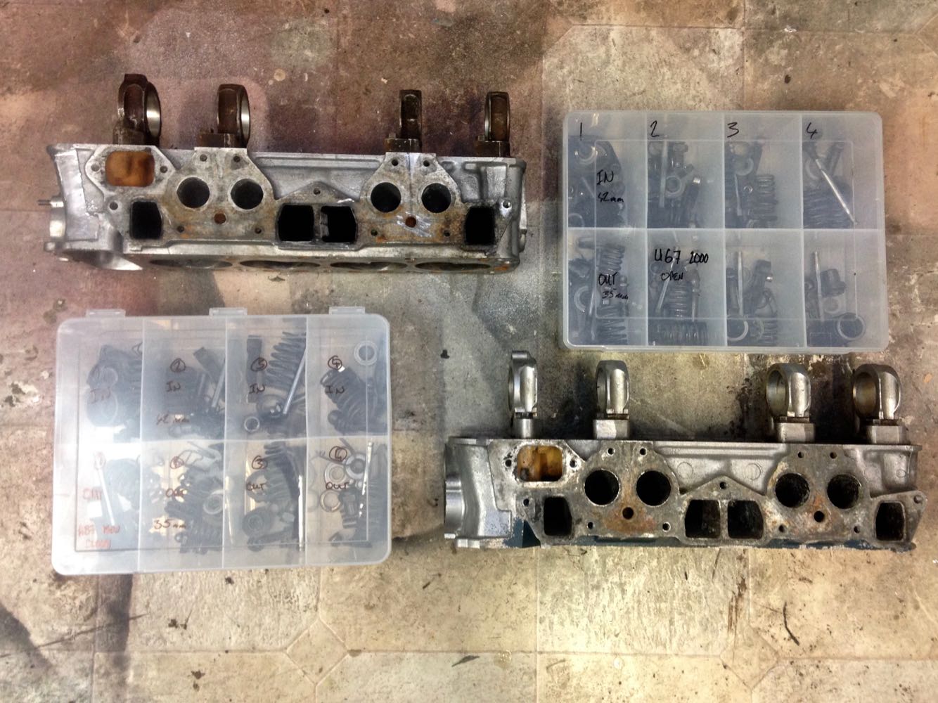
A while back I came across an L18 in pieces on marketplace, turns out the guy had started a build which got put in the back of the shed for 20 years and forgotten about, I quickly took possession and promptly forgot about it too! Late last night with the aid of 40% off spring compressor from Supercheap I stripped the head down, cleaned up the pieces and sorted them into an identical container to the L20b head. Both will be dropped off for a decent clean and hardness test, I will then crack test them both to figure out a build plan for the new EFI motor. Both heads have the same sized valves and exhaust ports while the L20b has slightly larger intake ports. The L20b head (top) is an "open" combustion chamber U67 casting while the l18 is A87 casting with the closed "peanut" chamber. With both the L18 and L20 blocks sitting there, i'm unsure which combo to go with so secretly hoping one of the heads is shot to cut down the options! Once the top end is sorted out, new pistons, rings and bearings will be ordered, I have a few different cams sitting on the shelf so need to research if the markings mean anything or if a re-grind would be beneficial to the overall plan.
1 point
-
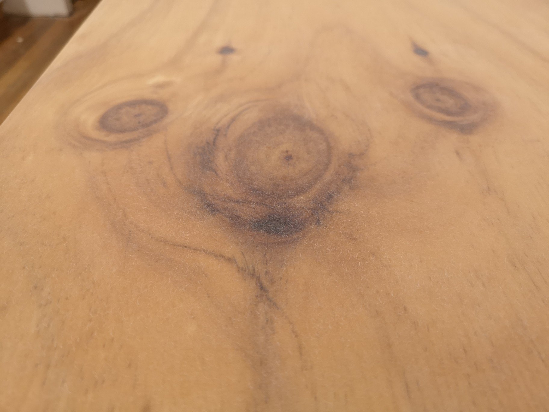
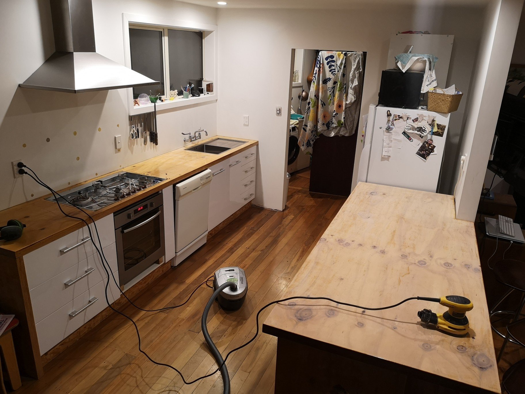
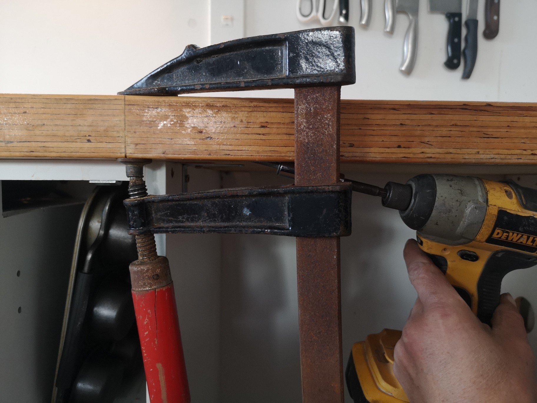
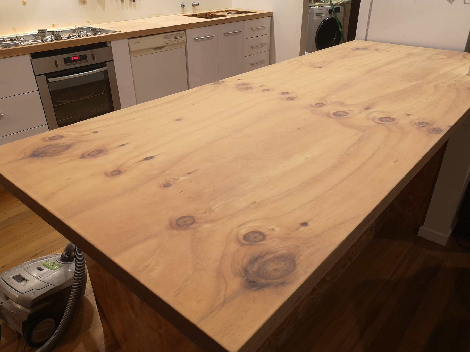
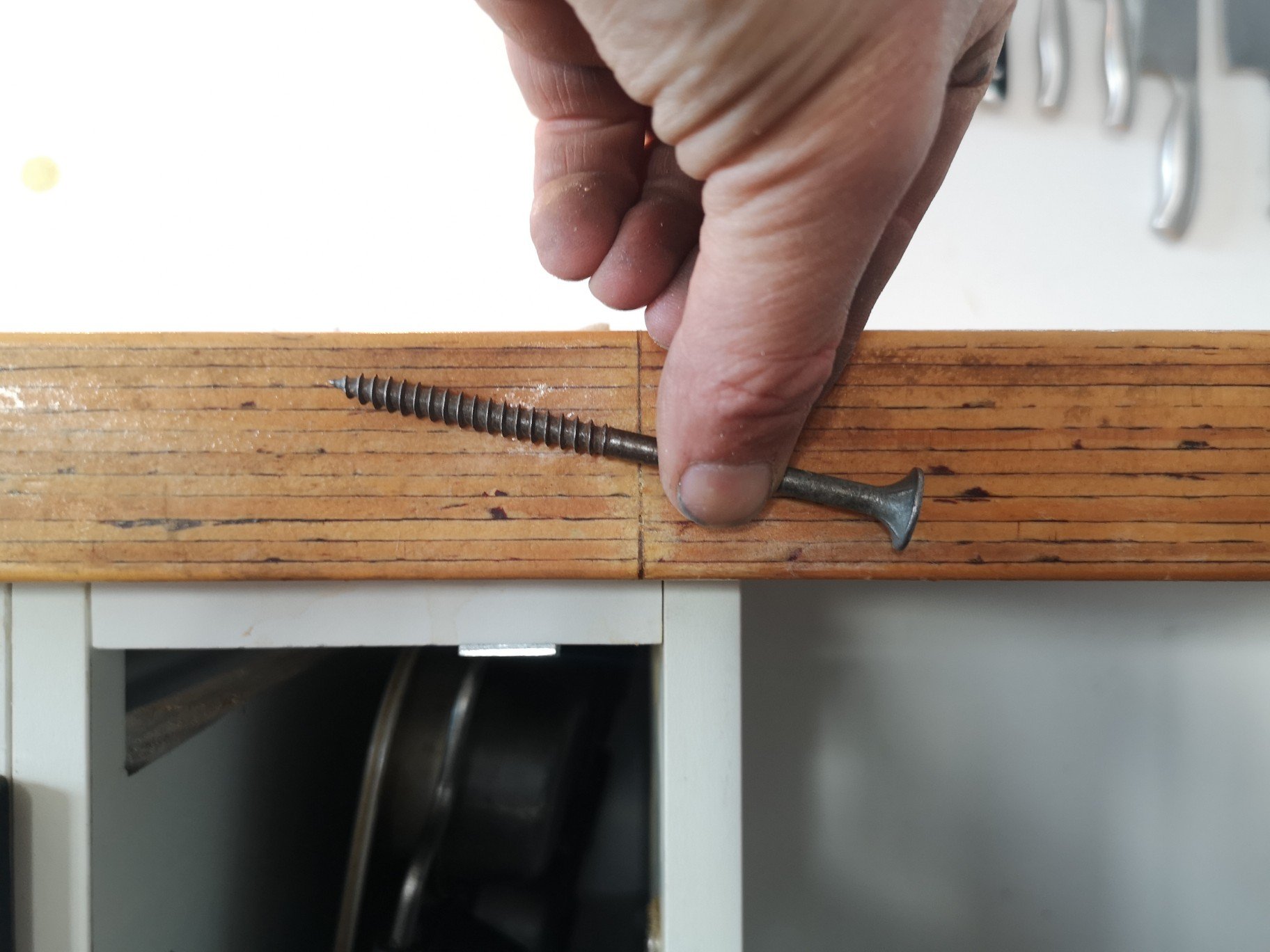
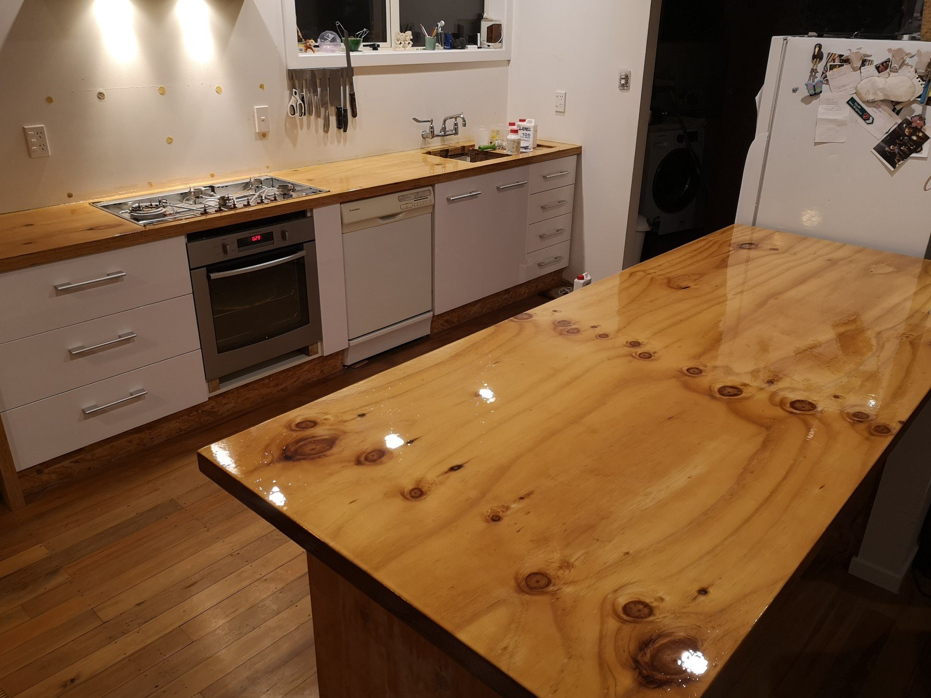
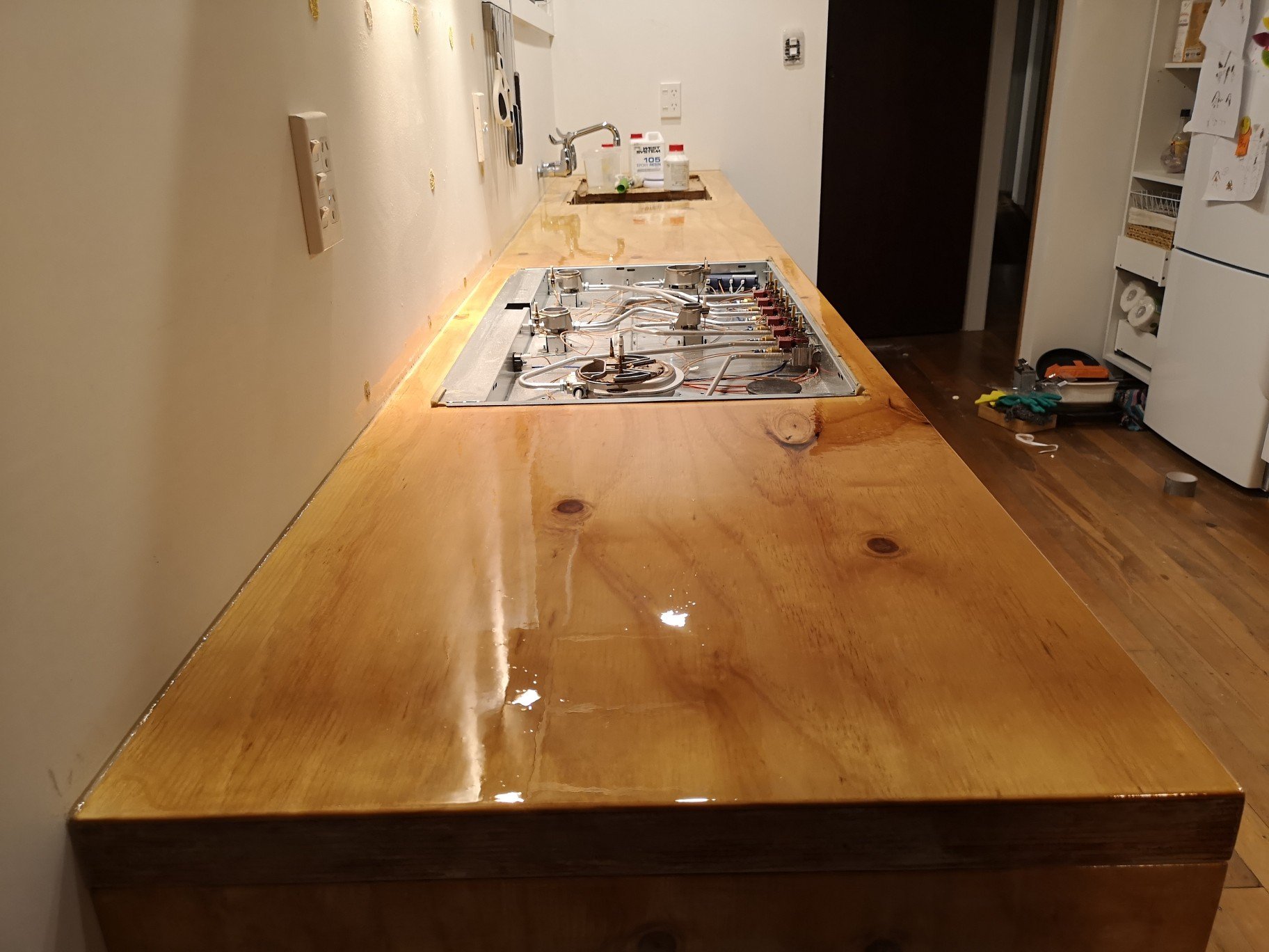
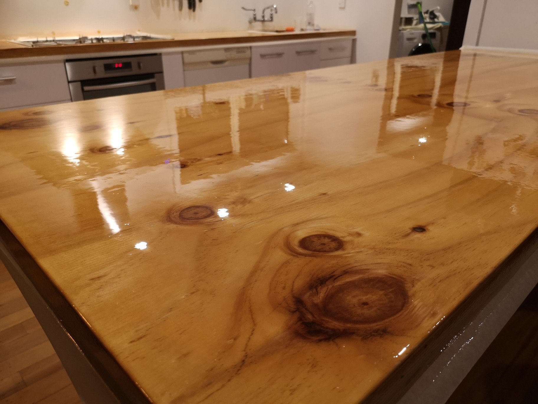
Before I set it in for good I recoated both benches in epoxy , the island bench was still ok but the wall bench was my first go and only had one coat on it that was full of air bubbles and was quite rough. It was also easily damaged. Before I started I had to repair the joint between the two sheets of ply that made up the wall bench, epoxy plus fuck off batten screw works.. Next I sanded it all back with 60 grit for keying purposes, looks quite nice just like that. Awesomely, the sander I bought last time I did the bench packed up half way through sanding the island bench, cunt, had to buy a new one. Went over it with liberal amounts of prepsol and gave it two coats of epoxy. This time I did it with a microfiber nook and cranny roller as it was too hard to do it with a window squeegee in place. Worked good until I went too hard with the roller and it broke leaving little bits of foam in the epoxy (FUUUCK!!!)... Plus once it cured there were a bunch of little fish eys in the finish Cue round two of sanding, Worth it tho, results speak for themselves. Much better finish, only problem I have is that next time I do this I'll be sure to strain the epoxy first as when I finished the older epoxy a big solid lump came out of the pottle after I had already made and applied half a coat.. consequently, what I thought was bits of roller in the first coat actually turned out to be bits of coagulated epoxy in both coats. I picked as much as I could out of the final coat but still missed a couple. Can always give it a light sand and polish further down the track... *probably won't....
1 point
-
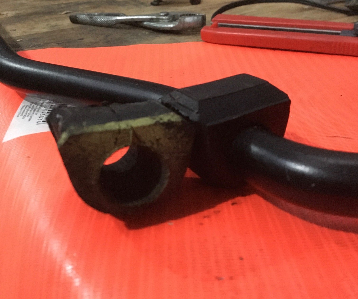
" Shimano? " you say... Well its not really that exciting. Please don't expect a Heath Robinson like contraption using XTR derailleurs, in the lovely pewter colour that the 965 series came in. Or better yet - some mint deore XT thumbshifters used as tensioners. Oh yes- the bike geek is strong in this one! But I'm jumping ahead again. First off - I needed a way to take drive from the crank while at the same time beef up a problem area. Now have a look at this next photo... See that big splined shaft sticking out. That was the main drive to the original clutch setup that resided in the removed rear casing. It had to go. So I chopped it off. I did have a photo that Hannah took of me chopping it off with a cutting disc (there was no way our bandsaw would have touched it) but I cant find the photo. However- here is a photo of that bit removed and now residing on our shelf of random bits.. Now luckily there is actually a flange on the crank. This was one item I had been trying to check before committing to buy an engine ages ago. I didn't know how think it was though, nor had I confirmed what the size of the six bolts were although I was fairly sure they were 8mm (but really hoping for 10mm). I was not going to be happy taking power off the crank, albeit its only 100 bhp propelling a little Imp and so I had a little think about it. I needed three things here. 1: a decent flange with 10mm bolts for the flywheel 2: a surface to run a main crank seal against because my engine design was going to have a sealed up oil bath for the oil pump drive 3: a larger flange to put a sprocket on. The design I came up with was an adaptor hub to bolt onto the existing flange using the six m8 bolts. But instead of just relying on the bolts to hold it I would machine it to a shrink fit and really make sure it wasn't going to move. Probably a bit overkill but why not. So I machined up this out of a rather large lump of steel (so filling my steel bin with a lot of swarf) It has two axial surfaces to shrink onto the crank- the flange outer and the stub I left over from the original splined sticky outy bit and clamped in place while it cools with nice new stront cap screws. Here I am tapping the threads for the flywheel hub.. Here's a small benchtop oven making things grow in size with heat and in the back ground is a crank just having recieved its new hub... In place and cooling down. Would be a bugger to remove now.. You can see the larger flange to which a sprocket will attach to. Now I needed to sort out a nice flat, removable surface to mount a potential idler sprocket and tensioners on plus an square surface to mount the oil pump driveshaft support on. I cut a piece of 6mm alloy plate in the faithful ( and noisy) tablesaw. I had several useful threaded bolt holes left over from a variety of the original transmission bearing holders, shafts gubbins and shifter wotsits. I machined up a little pointy bit of steel with an offset slot. Then I was able to screw it into a hole leaving the pointy end just proud. With my plate lined up where I needed it I gave the plate a smack with a hammer just over the pointy thing below, thus leaving an indent I could drill through. Repeat for the others and I had perfectly lined up holes... Cool. I could now support the oil pump shaft. I machined the end of it and tapped a new hole. Then machined up a bearing holder like so... Next little thing was to join the cranks rotating motion to the oil pump and make that rotate.... Hmmmm. I had to really think about this one. There was not a lot of room for industrial chains and sprockets. I thought about using a toothed belt that can run in oil like some of the later cars. But apart from the prices (!) they are not available in many sizes and are apparently prone to throwing their toys from the cot. I couldn't run a dry belt due to the bottom half of this area being part of my new allocated sump capacity, not to mention sealing it would be very tricky. So really- chains and sprockets were the best choice. Why 'chains' and sprockets? Not just one chain?... Because I wanted to drive the Honda pump at or as close to the original speed- which is slightly under driven. This way I would be sure that the pressure and volume would be about right. No ifs or buts. I didn't mind going slightly faster because the stock goldwing has a low oil pressure at an idle of 11 psi at 800-900 rpm. I'd be happier if that was a bit higher. With this in mind I had already worked out roughly what gearing I would need to be in a certain range. I had worked out the original gear ratios and then used a gear calculator to play around with ideas... But what chain and sprockets to use? I enquired with so many places and had done loads of internet searches but the answer came to me when I lifted one of my bikes down from the wall before going for a ride. Of course! Bike chain, chain rings and sprockets! At first I worried about the strength and durability but thought about the abuse my chains go through, especially on my singlespeed MTB. I have only broken one chain and it was after it had been jammed. Over about 15 years of being a bike mechanic in several different shops almost all chain failures I had seen were due to something else cause them- unless they were a cheap unsuitable chain. So I went through my varied collection of chainrings and cassettes (I have many) and selected out the ones with a tooth count that would work and fit. I machined up a spare shimano freehub to take bearings like this... Machined out a Shimano mtb chainring and cobbled together a mock up to see if it might just work... It looked good but I was not happy with the 3/32 width ring and sprockets. Even though they will be in a oil bath there was still not a lot of thickness to the teeth. I was not expecting this engine build to do Lexus levels of mileage but I wanted it to last long enough to do some good hoons for a few years at least. I had enough room to go up to 1/8th width chain but no more. I looked into BMX chainrings but very hard to get the toothcount I needed and sprockets were much the same- plus bloody expensive when going odd sizes. So a mate at a local engineering suppliers priced up some american sprockets that I could grind/machine down. Wow- cheaper then shimano stuff and tough as. I bought a set of four and set to turning them down. Not easy- in fact it took ages as they are induction hardened teeth. But I finally took them down from 5mm to 3.3 and they fitted a spare bmx chain I had perfectly. Much more sturdy... I have now got a very durable bmx/e bike chain that has flat straight outer edges on its plates- this will suit my tensioners. I have a couple of tensioner ideas to try and think I have nailed how to make them easy to fit and effective. Remember- I want all of this lots to be super easy to unbolt and swap out. Its all a totally unknown design with regards to longevity so it needs to be easily serviceable. More soon ...... Alex1 point


.thumb.jpeg.e0a4bff61111e0c8c7396950fcc94da1.jpeg)


.jpeg.4d8083cd0d545fde0dc2963bd650c379.jpeg)


This leaderboard is set to Auckland/GMT+12:00