
Leaderboard


Popular Content
Showing content with the highest reputation on 04/22/24 in all areas
-
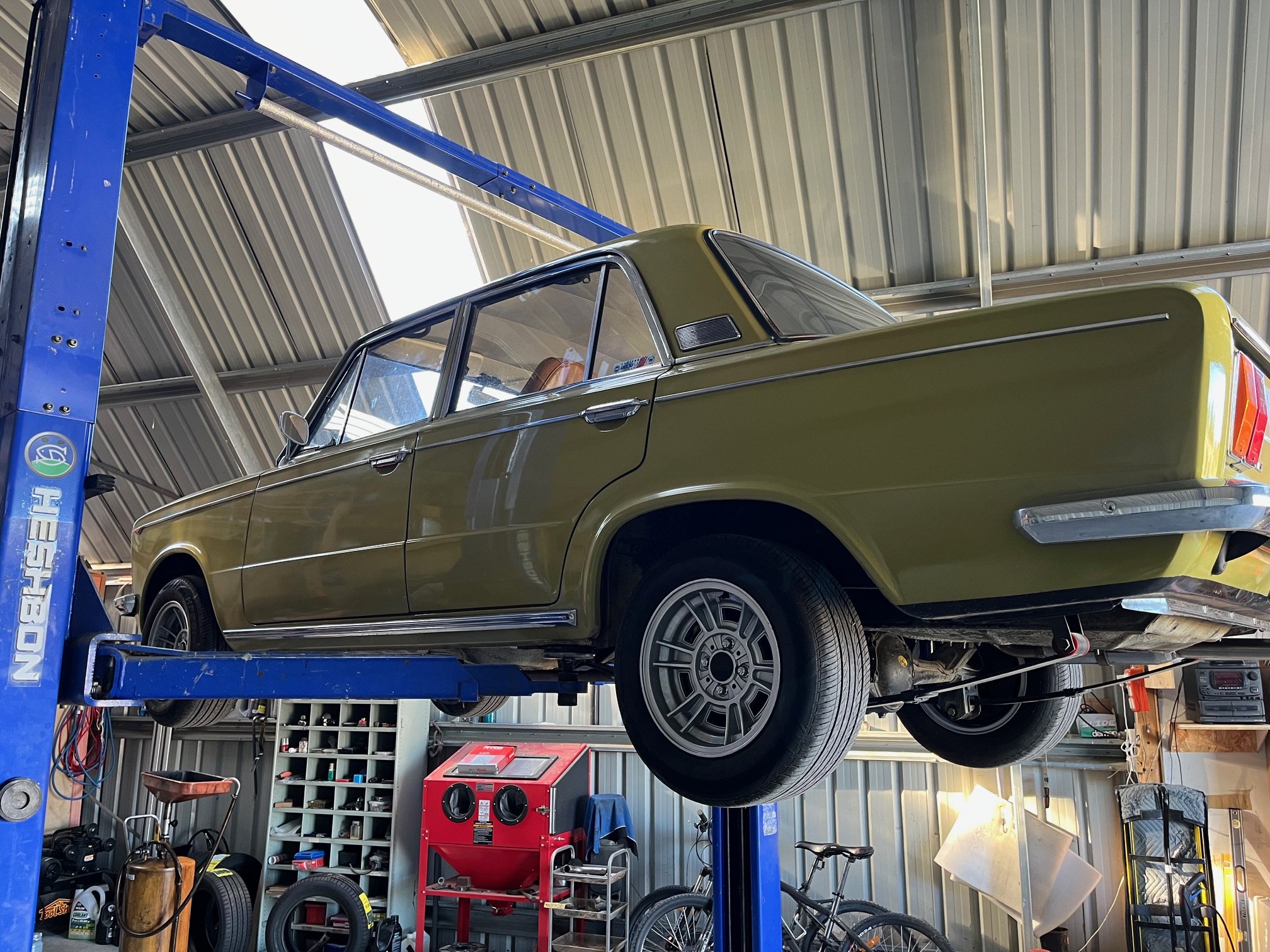
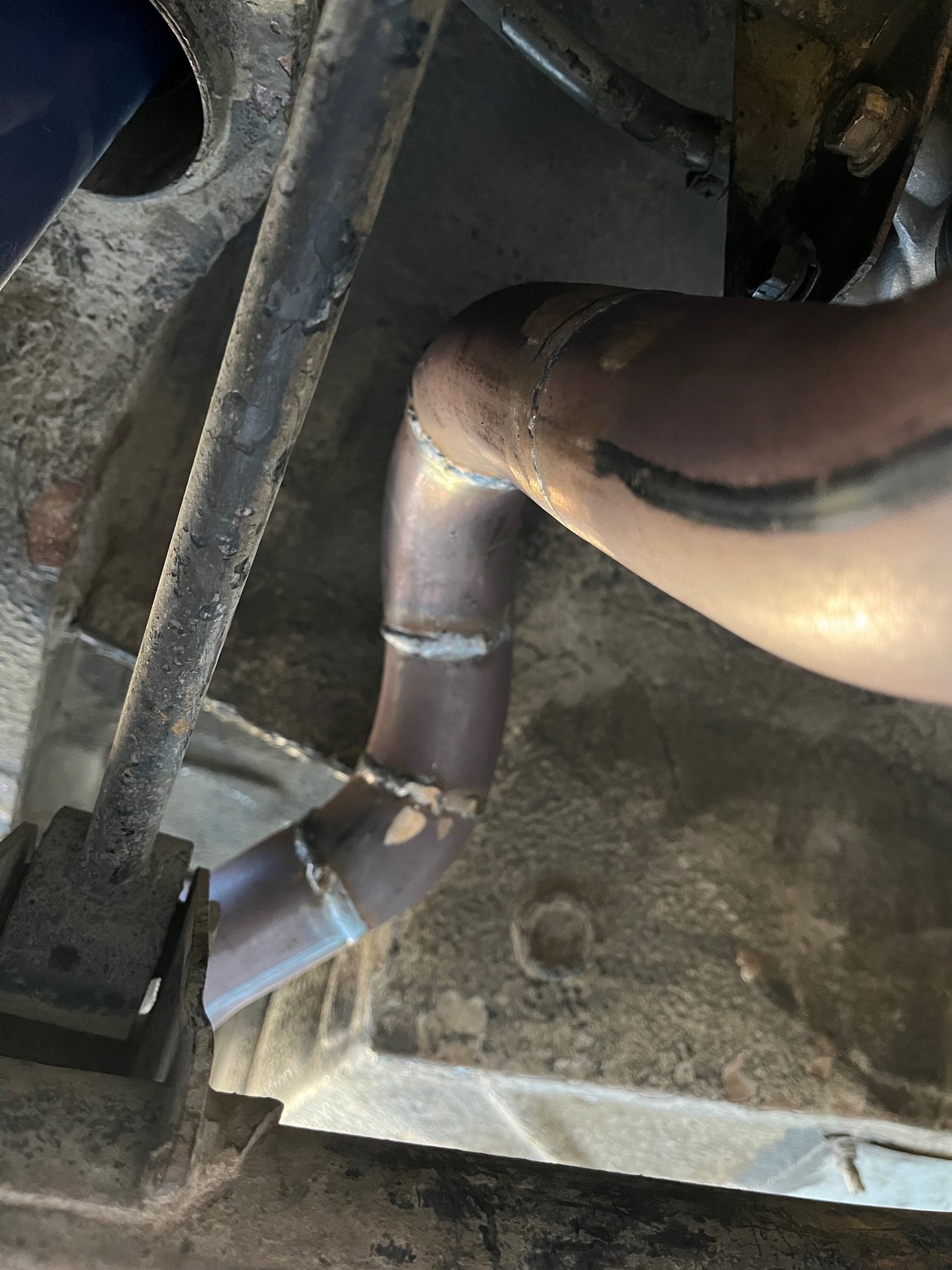
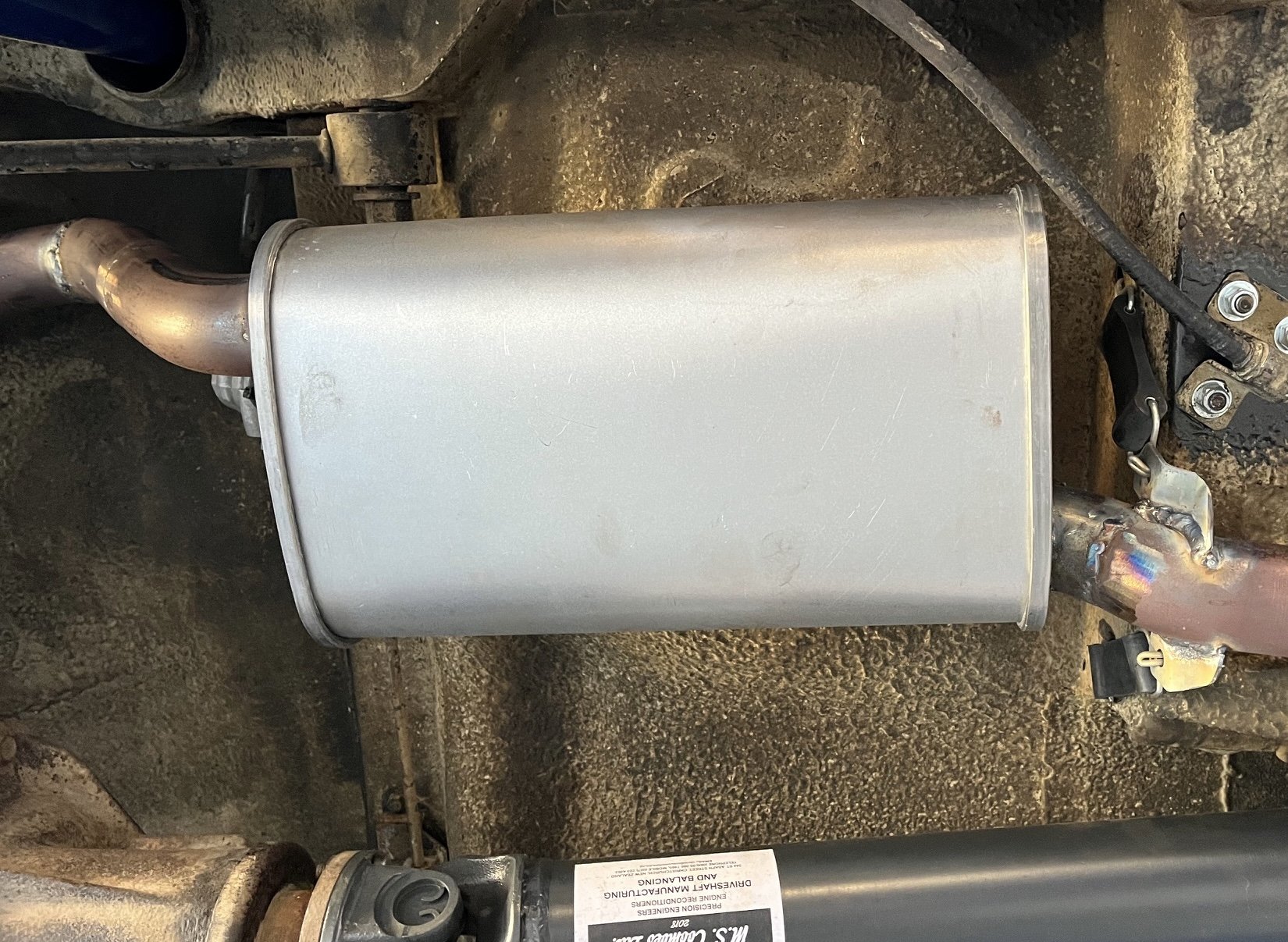
1000km post run in oil change time. Then I took it in for some surgery on the exhaust. I got sick of playing around with it so like a coward I farmed it out to a zorst wizard. There was much choppy chop and a quieter centre muffler was grafted in. Still sounds good but is now bearable to drive. Wizard made multiple angle adjustments to clear the diff and brake bias valve and torque arm. One problem to report: Whiff of antifreeze when the heater is on. GROOOAAAN!! Looks like dash out in my future.
 12 points
 -
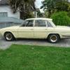
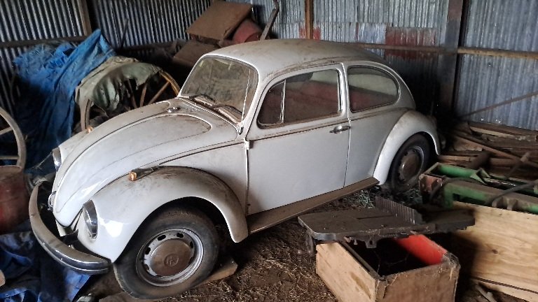
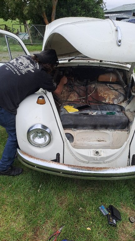
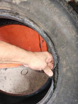
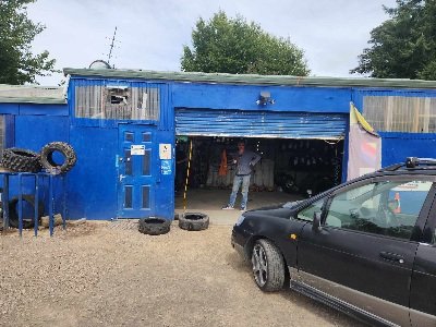
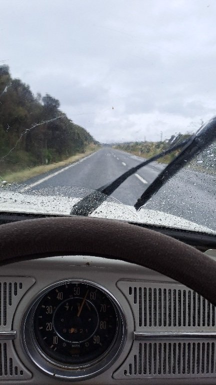
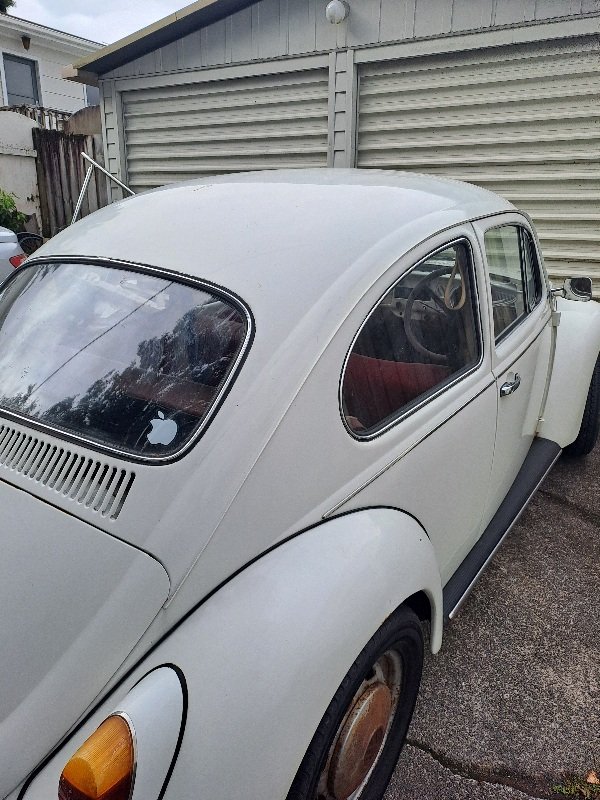
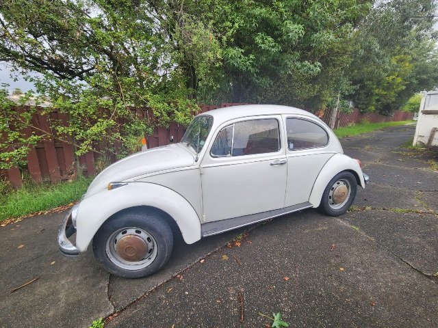
Not too long ago around Xmas I had heard that there was developing interest in my Auntys beetle and so in oldschool fashion I acquired another OS machine to add to my collection. To fill in some blanks we need to go back to 2007, I had a brush with the law lost my license and moved to Surfers for a few months for a cool off period.During my time there I got the use of this thing to commute around I had 2 jobs over there one a part time job at a tyre shop and another washing dishes up in Sanctuary cove at a high end seafood restaurant. The Lil bug was great and I only had issues with fuel delivery when it got too hot. I'd push it over to the side of the road between surfers and Miami and wait a while for it to chill... once I got fed up with part time work I managed to get a fleet job with Baurepairs down in west burleigh. First day on the job being kiwi got the general hazing from the lads and they got it back in equal amounts, they all enjoyed commies and falcons as long as it had a v8, so here we are with the Lil herby puttin about with a raspy exhaust note. Couple weeks later one of the lads had car issues and broke down and was resorting to the bus. I offered a lift as it was on the way home. Needless to say he was reluctant. Oh well suit yourself. Next day I offered again and he decided ok sure. We cruised along and headed up the coast towards his stop. At one of the lights I was waiting to turn right and this guy was beside himself, next to us was a beach blonde in her own bug waving at us. I wasn't paying attention and so I finally had a look and she was alright to look at. I played it down, so the next day he gets to work telling the crew about the ordeal and the bug is now dubbed a pussy wagon. The crew then insisted we do a Roady to Byron Bay via nimbin. It was a great time had by all and a few yarns about nimbin could be told. Better to not sharn on about that too much... back to the main yarn. A few years later... and a few more to be exact Since then it was exported to NZ about many years ago where it got parked in an old hanger and left to gather dust. I developed a curiosity about will it go and maybe putting it back into operation. At xmas last year I headed down to drag it out and see if it was still in one piece. Someone had wired fuel pump on backwards as I heard it bubbling into the tank so seemed like someone had borrowed the fp and then put it back. Got a fresh battery and a while later it barked into life. Dry rotted and coozed tyres were next on the list. 60 bux later we had a set of roadworthy treads the fronts were bad but they held out. 5 Hours later rolled into the 09 and parked her up. The was a mean mission. It's been parked up for the last month just waiting for garage space to accommodate this so we can begin stripping and assessing in conjunction with the viva
12 points
-
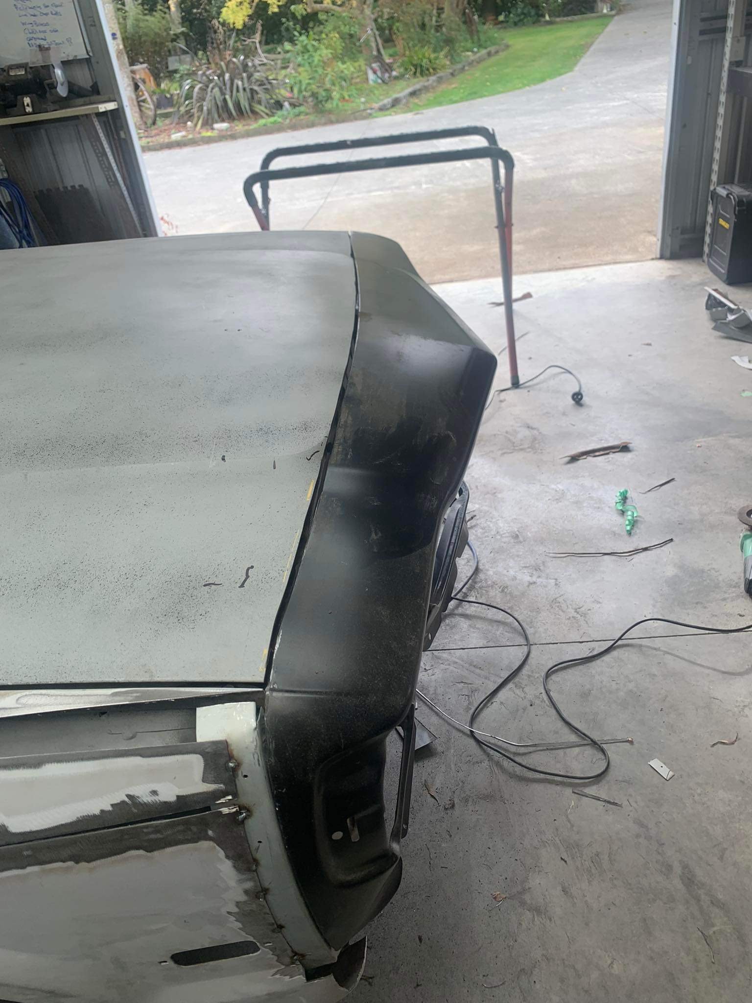
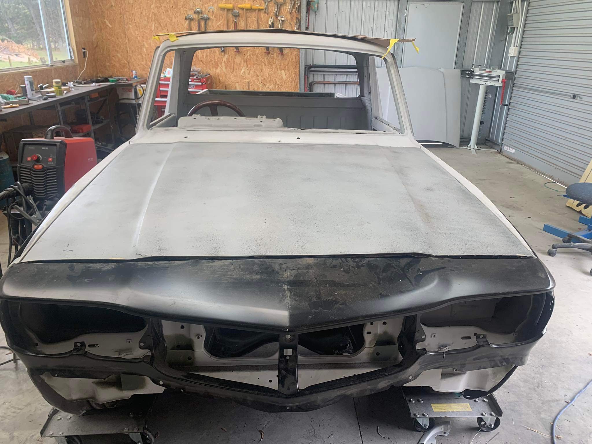
As per the title this next stage of building the exhaust silencer/muffler/back box/ take your pick has taken much more time and effort than I had always expected. I started by taking the blue imp apart. To Woolf valley garage I went.... ..where I removed (rusty mild steel) exhaust, bumper and rear valance.. Popped it onto rusty imp shell... Now I knew exactly how much room I have to play with. Whatever I was going to build had to work with several things. I wanted the box to be mounted higher than the existing one behind the Datsun engine as I was sick of scraping it on steep driveway exits. It had to be built completely of stainless steel, no exceptions. No more corrosion. It had to look tidy and fit within the bumper line, tailpipes excluded. The tailpipes were to be twin centre exit. I had a very specific look in mind and they have to be just right. It had to be quiet enough and yet still sound sporty. This last one is tricky and will most likely need modifications to get right hence the last design point... It has to be modular, easy enough to disassemble and repack with sound deadening (most likely glass fibre) Now I knew the size I could build it to I started by making some flanges. This so I can unbolt the flexible sections between the V clamps and the box. Made to suit the 44mm tube as per the tube off the V clamps. Lifted the big folder we'd made onto the bench top and folded up some 1.2mm stainless. Although heftier than I could have used I've gone with this thickness to helped avoid the tinny sound thin stainless boxes can make. I wanted perforated stainless tube but couldn't find any within NZ. Got some perforated sheet instead - again 1.2... Which I cut strips from and formed up into tubes as such... Welded... Now I had the start of a box and some tube. I could sit down and nut out a design. I have had some basic ideas for ages on how it might look inside but it was really good to sit down and see how it might work. Drew some ideas up.. Nutted out something I think would work well and be easy enough to change if need be. Time to commit. I had to cut some blue steel. First actual act of modification to the imp in my quest to plonk a flat six in it. Now I could double check box sizing and weld the flanges in place. Folded up the second box side.. Complete with captive nuts to suit a lid.. Tail pipe time. I almost went with twin 2" exits but they were just a tad too big. Settled on twin 45mm. Tacked them to yet another stainless pair of flanges to work with the modular design aspect. Happy with the look I then fully welded them on the inside. The flanges will be sealed with a soft copper gasket. Happy I had the look right I cut the centre top from the box, created a recessed bit and carefully welded in the second threaded flange. So now I have inlets and outlets where I want them and just have to connect the dots. Ideally a nice long a route to dampen sound while keeping it as smooth flowing as possible. Plus, as per original brief, it has to allow for easy disassembly and re-packing. There was quite a bit of head scratching with this bit of the build but eventually I sorted a design out. I cut various bit of sheet and put big holes in them with a nice brand new holesaw set. Made little boxes with more big holes... Shaped bits like a heart...(#putmyheartandsoulintoit.....) Welded the ends onto the main box, curved in bit to help with flow and also hide the external bobbin mounts from view a little. Now I had a collection of parts that would come together and form a london underground of tubeways for the exhaust gases to follow. I was pretty happy with the layout for its potential silencing effect. However I now wondered if it might just end up being a touch too quiet and restrictive. Luckily I had come up with an idea early on where I could add some valves. Quite a little bit of extra work involved but the more I'd thought about it the more I was convinced it could work well. With this in mind I had built the middle chamber width to allow for some valves and made sure they could be removed to fit said valves in place. I cut some 44mm holes in the middle chamber lids and made some to valves to suit... Whipped up a little press form to create brackets.. Valves mounted. Underside of lids have the heart halves which help direct flow from one tube back too the next, or up and out through the open valves.. Valve shafts stick out through back of box. Sealing will be by a combination of spring loaded fibre and silicone washers. Now for an exciting point in life that every shed 'Barry' looks forward to. Emptying out those boxes of little random fittings that have been stashed away 'just in case you might need them'... Such fun! I selected my (stainless!!!) treats and scribbled on some alloy. Made lots of alloy swarf.. Ended up with these levers. Pinch bolted to the shafts along with added grub screws. The short length of threaded rod will be changed for a long length of stainless rod, actuation method from within the car yet undecided. Possibly a 12volt door lock motor etc or maybe mechanically with a bicycle cable. Recessed the backs to allow for seals.. So yeah. Lots of parts! Compulsory photo of thing exploded into many bits... All together now with some arrows. Remember each side is just a mirror of the other side (there is a small cross over hole in the centre plate that separates the sides) Valve closed... Valve open... I think it'll be quite a difference in sound and look forward to hearing it. Valves can be seen in action in this very exciting video... So It's pretty much complete except for the mount points which I'll do once I've got some bobbins from engineering shop along with seals. The lid will be sealed by running a bead of silicone which I'll let set before clamping the lid down. Oh I weighed it too. I was worried it might end up quite hefty but it will be only about 6.4 kg once all the bolts are in/packed with fibreglass.. The box will be painted satin/matt black leaving the tailpipes shiny. Silencer mounted in place... View from above showing plenty of room for the valve linkages in place. I ended up cutting a tiny bit more of the valance away so there's room for a stainless heatshield. I then covered the valance with some masking tape to help prevent it getting too scratched while I put back in some internal strengthening and capping it all off. I'll also be adding mount areas for the bobbins. I'll remove the engine next and add in the big multi-pin connector to the engine loom. Then I'll be seriously very close to removing the Datsun engine and cutting out the under seat area just as I have on this rusty shell. Wow!!12 points
-
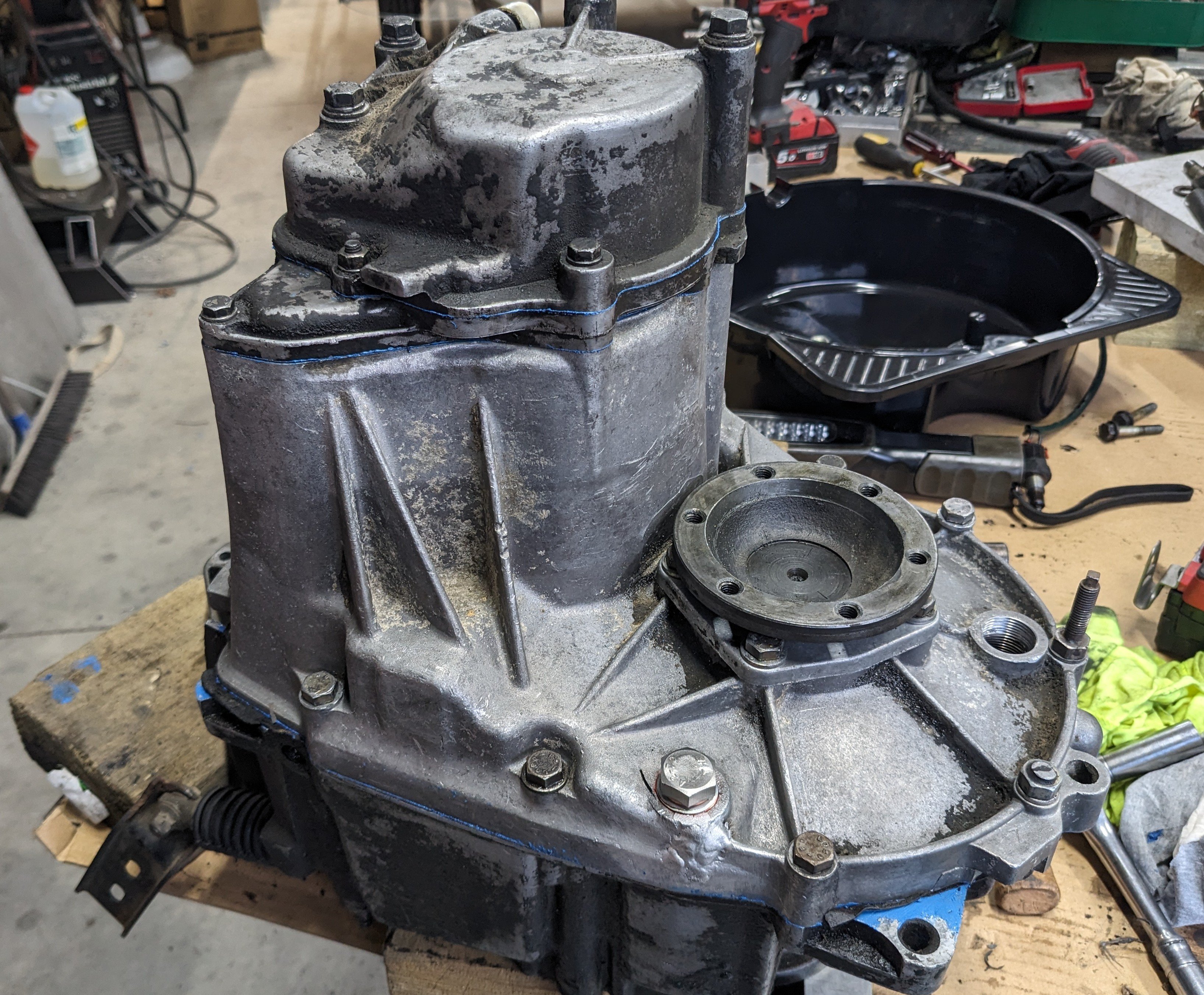
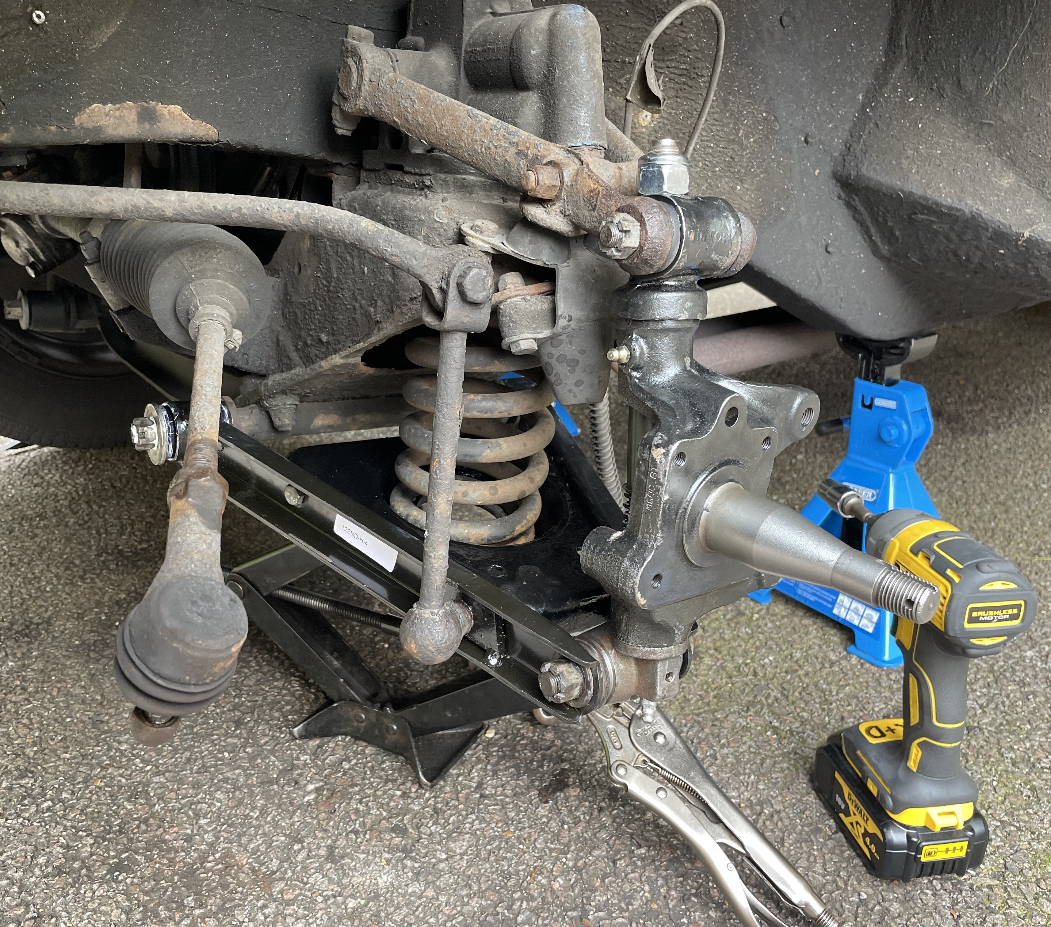
I got it all back together and has all of its gears so I'm calling that a win. It also does not appear to be leaking any transmission fluid, another win. So then I looked to the wheel bearing situation, and smashed that out. There is a dedicated X1/9 forum, Xweb, which has a lot of excellent info and how to's. I found a great pictorial run through of the process and set to. I did need to make a special tool to remove a locking ring but that was no drama. Octagonal lock ring fuckery. Special tool made by a special tool. That and the engine going in meant Sunday was quite a big day, so I left the tie rod end for tonight. On the basis of this minor last task I booked the car in for its recheck and a wheel alignment. After work I went down to sort it, only to find that the rod end is the wrong one, and about 50mm too short, GAHhhh! It took two weeks for the last one to arrive, I am so disappointed. Anyway. Previously to this weekends shenanigans I had done some messing with the jetting, and drilled the mains out to 130 from 125. So I took it out for a short run so I could bleed the cooling system properly and check the AFRs which were much improved, as was the idle to main circuit transition, so that at least was good.11 points
-
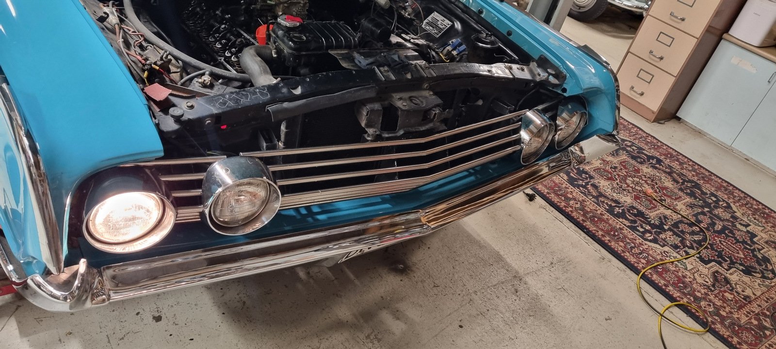
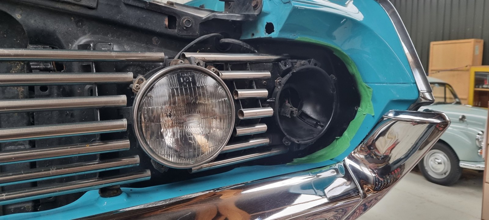
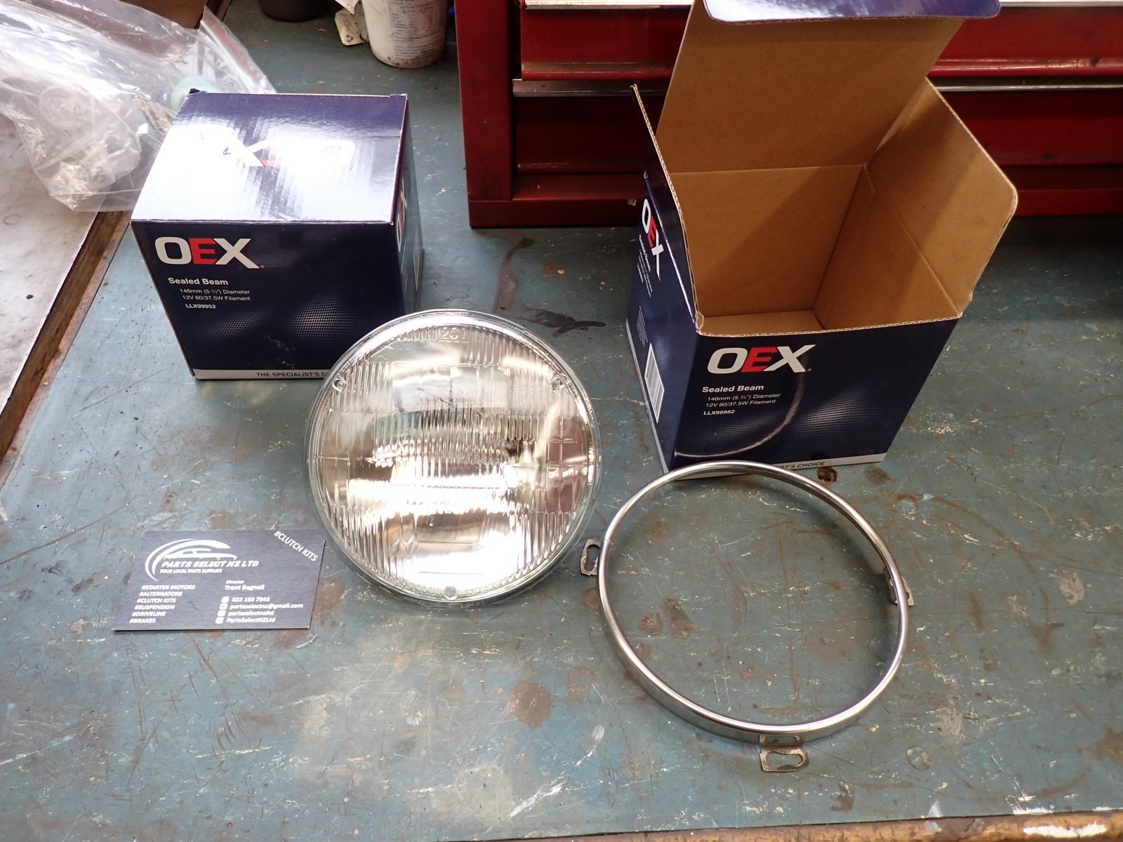
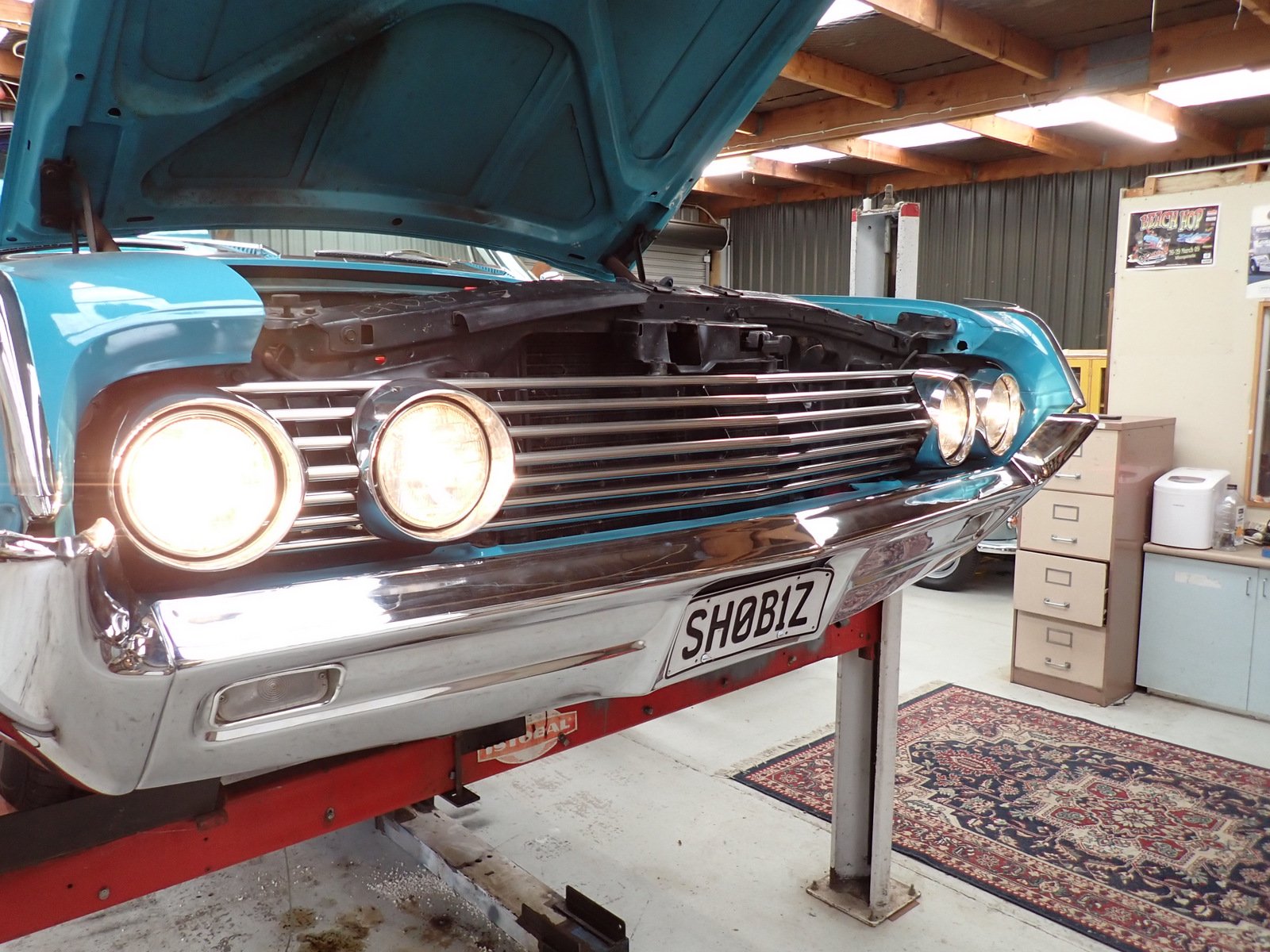
One outer headlight (dip/high beam) gave up the ghost during Beach Hop. I installed these when the car came to NZ in 2003, so last 21 years, fair I suppose. The working one looked a bit sad too so I though I'd replace both. The centre high beam set are the ones it had in Indiana and seem fine. Took them out and cleaned up the buckets (I ended up doing all 4) followed by a squirt of Black Zinc. I did the same for the small aluminium trim pieces that go in where the masking tape is, and the blacked-out areas behind the grille that were a bit scruffy. It turns out that modern Hella lights (stocked at BNT) are all semi-sealed and don't have the nice domed shape so I got a couple of 5 3/4 sealed peams from PartsSelect on TM Let there be light! Also picked up some used PP from Trademe.
10 points
-
Following Kelvin's success with his lowering rails, and girlface's "well it's a quality of life improvement, not a performance upgrade" concession, I nabbed some as well. I wanted to get some adequate before and after's but I was on my own so... we'll start with me failing to fit an upright Suica card above my head. I started with the passenger side - also using Kelvin's patented "do it in the back seat" approach (hmm phrasing) - and I had a couple of brain scratchies around the belt buckle that took things later than I wanted but figured it out eventually. A tricky driver's side before and passenger's side after the next day. Riveting On to the driver's side... and well, there's not much more than to show some before and after's. There's more than a whole Suica card's height now! I kept the driver's seat in the same angle while upgrading it to try and keep these two eye-level shots as close as I could. I can actually adjust the wheel down! You can see my hair! As Kelvin said, "it really does feel like you're IN the car now", as opposed to riding on it. It no longer feels like I have a vertical blinder on. I can more easily see under the front-view mirror. My hair doesn't scrape the head liner, regardless of seat incline. I don't have to recline the back slightly past where I'd prefer it to be anymore. And at the other end my butt's position in the car feels more planted and nestled. Overall 10/10 upgrade. I can't wait to drive it again.7 points
-
So it looks like this is a thing. I have entered and paid. I'll be co-piloting the Sigma down from Tga with @MaxPower. The mighty Sigma is being handed over to its proud new owner at Hamner so We are looking for a ride from Hamner to Chch Airport on Monday morning. I think our flight leaves around mid day. @HighLUX will probably be joining us too. Can anyone help with airport transfers?7 points
-
5 points
-
Leave booked pending approval4 points
-
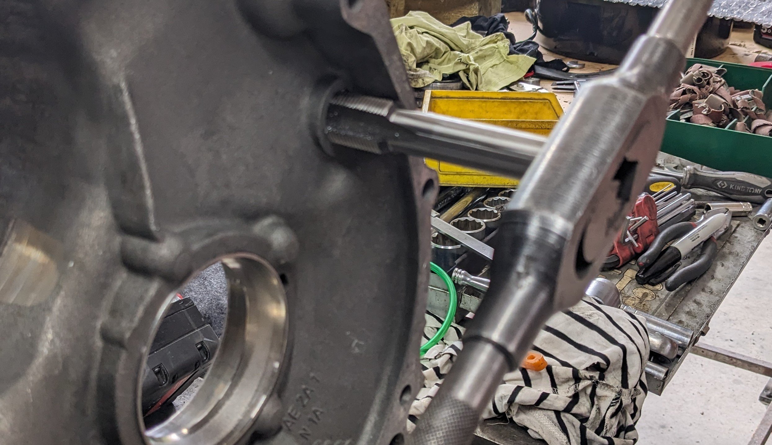
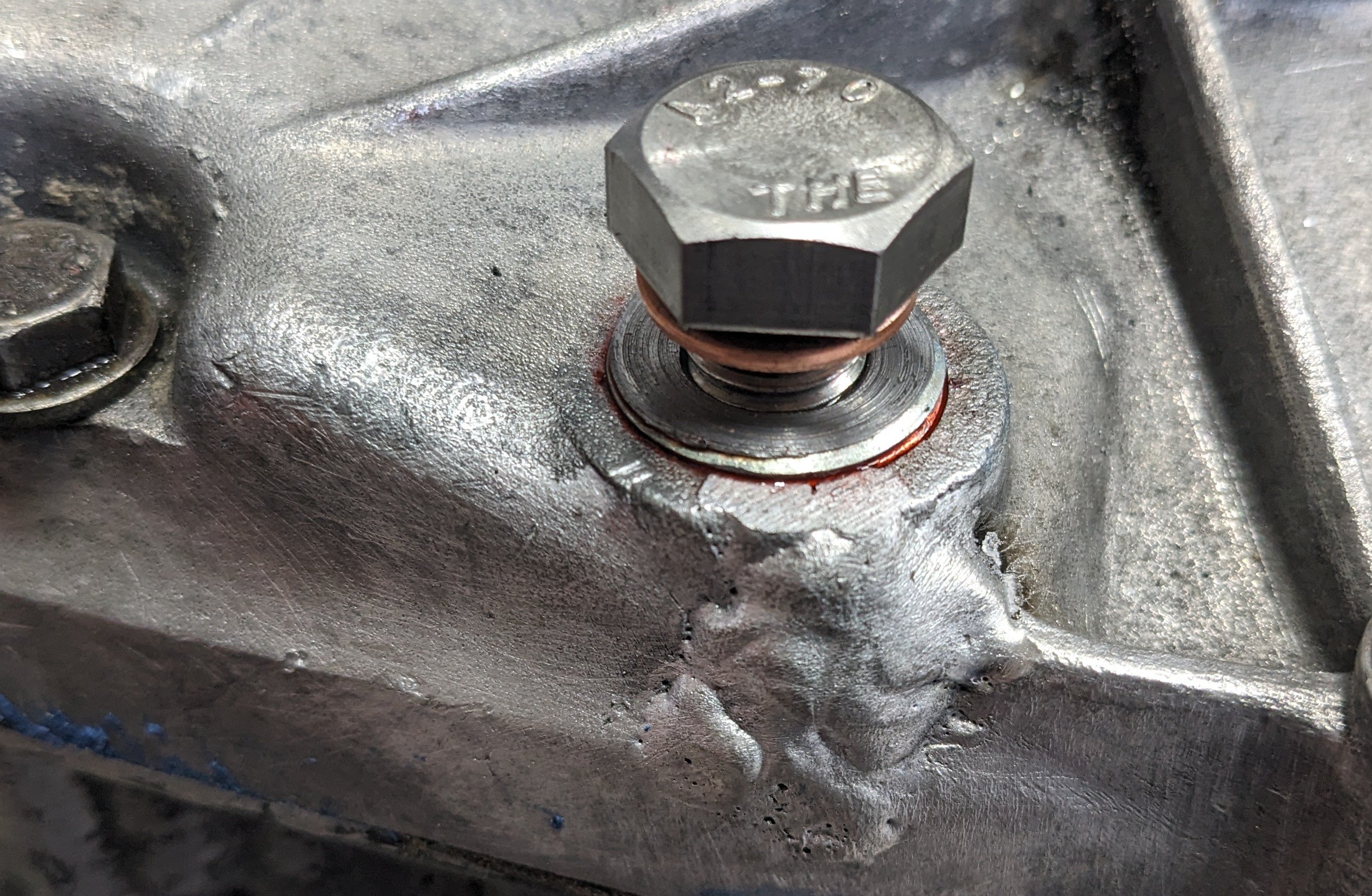
I did a thing. First I went to visit @yoeddynz who kindly welded the crack up. I also got a preview of exciting Imp developments.... When I got home I had a look to see what that plug thread was. Interestingly it appeared to be an M22x1.5 parallel thread, which meant a tapered plug made very little sense. And it just so happened that I had an M22x1.5 tap and some threaded rod. So I messed around for a while to get this; I put some pretty mega threadlocker on the insert, so it shouldn't go anywhere. Now the fucked shaft. It was pretty obvious that the broken bit wasnt a new development, and that the box had basically been working ok like that, so I did the obvious thing and just put it back together with the broken bit back in place, retained by the gear and the retaining nut. It feels fine. I figure that worst case I lose 5th at some point, by which time I will have a new box to go in. I will lift an optimistic pint to that notion tonight....
4 points
-
All of which is getting silly - simple rules for what should be a simple system. Annual wof's for all cars.3 points
-
Yeah was figuring all of that would be the case and was wishfully thinking it might have got easier, nothing is ever cheap being 1 off. Sounds like I'm going the aluminium route, i've take the time pressure off myself as i want this done right, so I can spend some time mucking around and see how far i get. Yep still WFH most days, thanks for the offer, but i'm probably ok to proceed at this point (but if you ever want to pop round and check it out just sing out), if not will give you a yell Thanks everyone for the thoughts/advice appreciate it!3 points
-
I had a one of those sentra gt cup cars as a road car when i was young fella, they had no 180kph speed limiter and I got the thing to do 195 down one of those long big hills on way back from akaroa. It was whiteknuckle stuff, sounded like the world was coming to an end. Only every did it the once. I expect this to be every bit as terrifying at pace too haha3 points
-
Registered. I put in the daily as the car i'm taking but no doubt the wounders may have something better for me to take Maybe wambulance camping? maybe the vehicle I have for the next challenge? maybe just a boring daily3 points
-
Some random Vauxhall green from Halfords
3 points
-
3 points
-
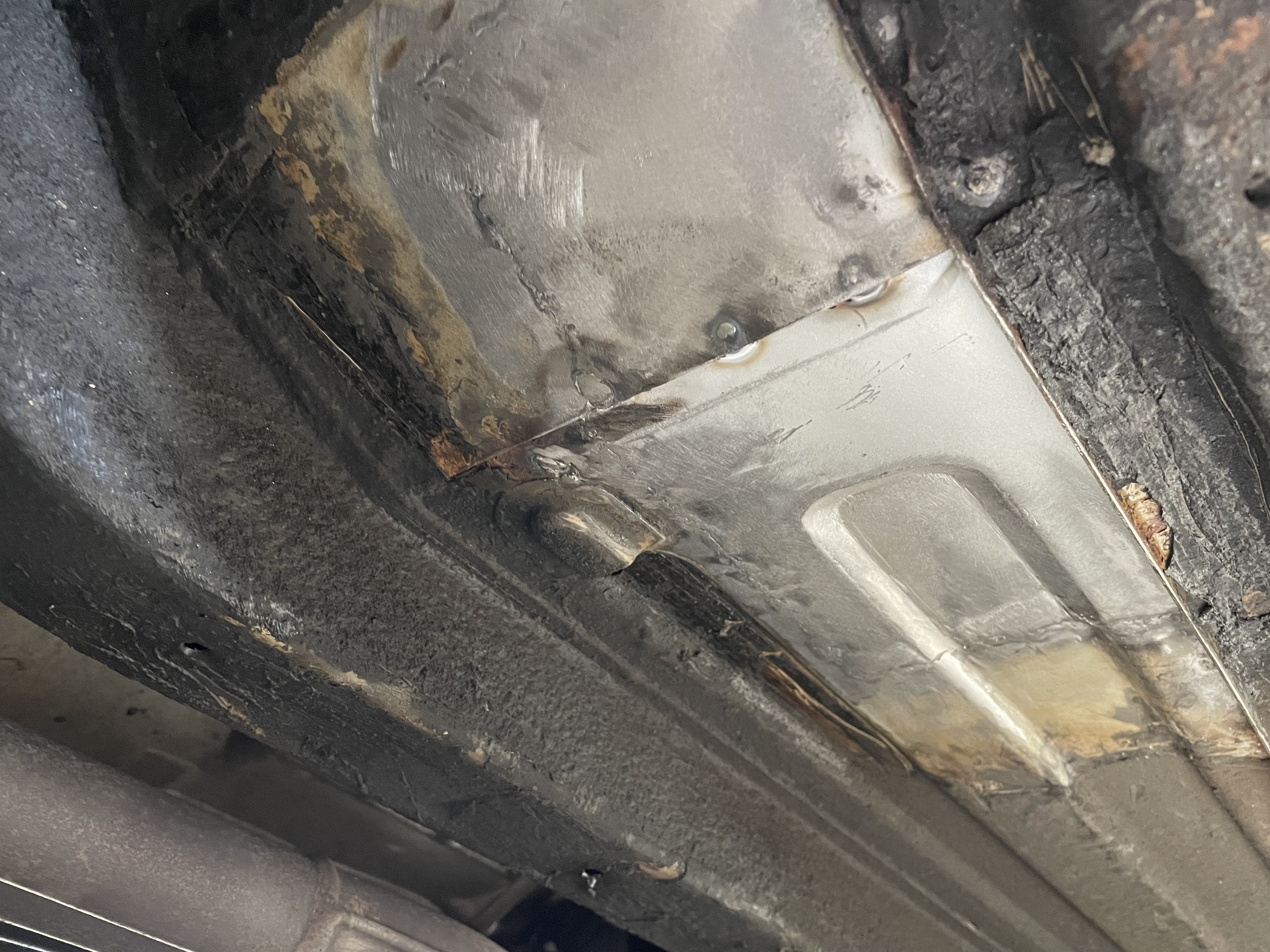
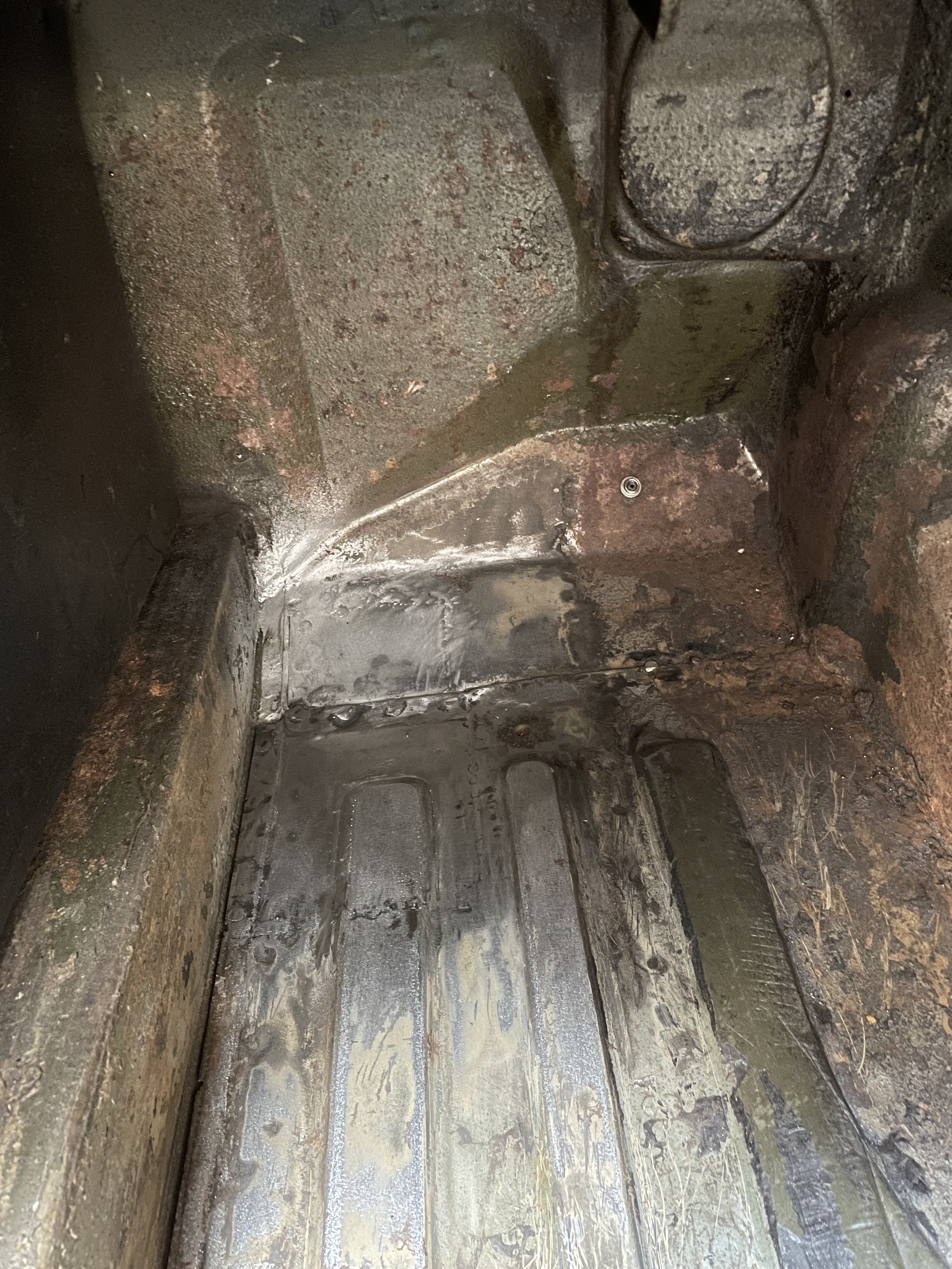
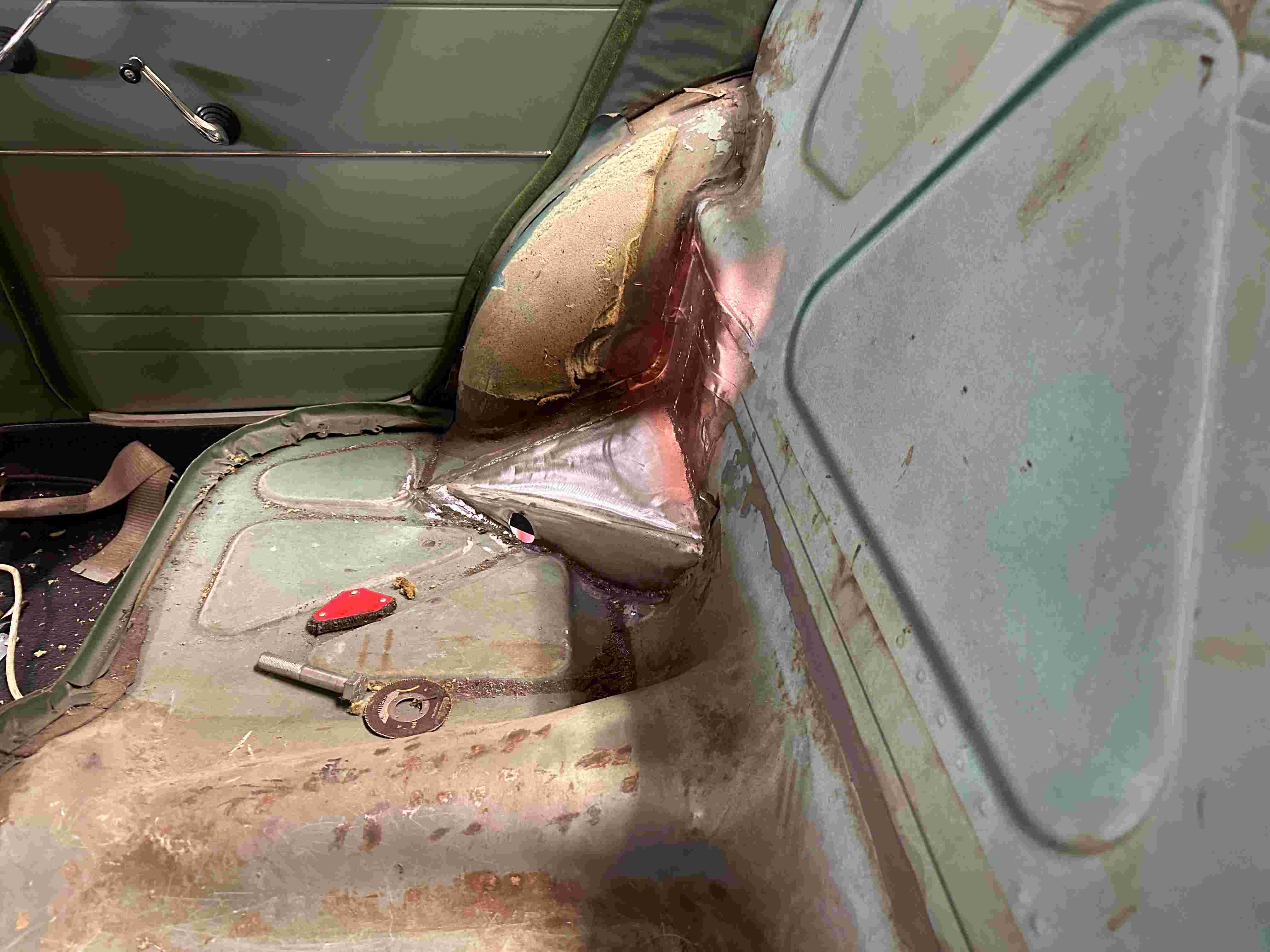
A bit more progress with a fillet piece welded in and the sheet metal replaced covering over the fish plates etc. I have also replaced the section I had to remove in the rear seat for the top trailing arm on the drivers side.
3 points
-
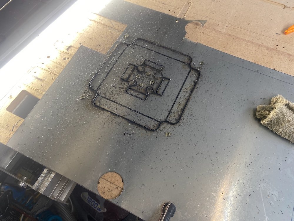
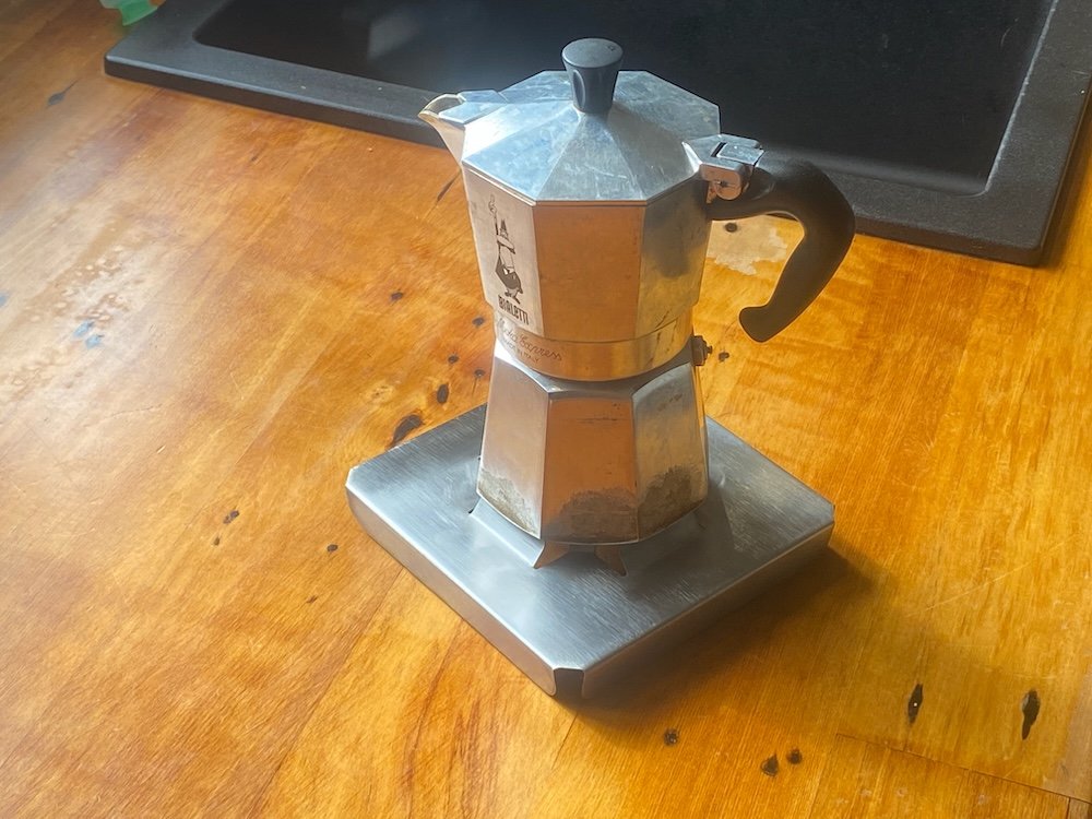
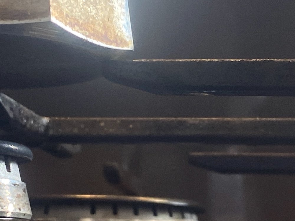
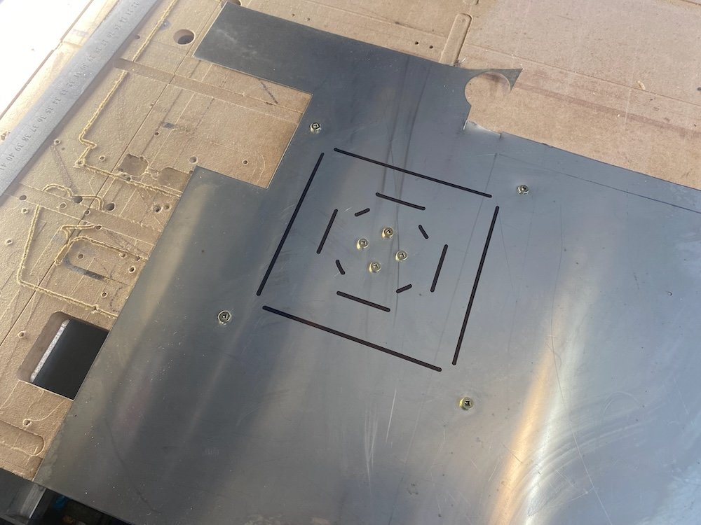
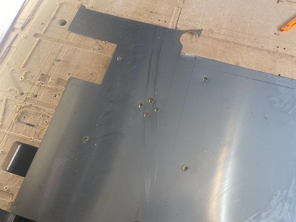
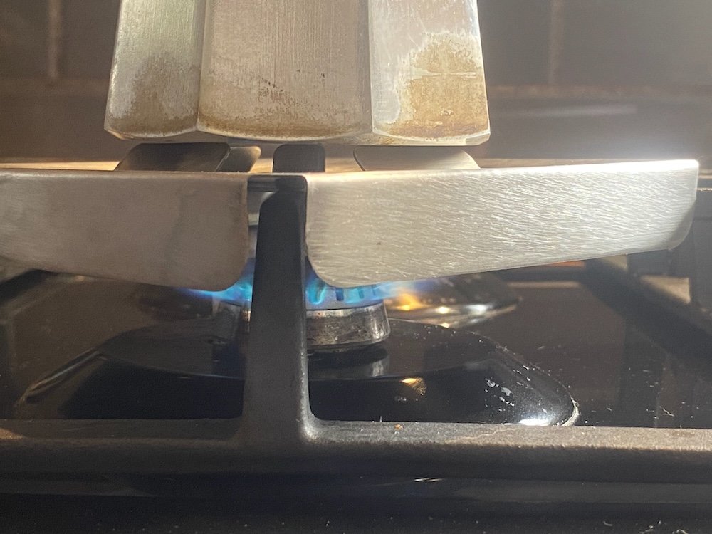
Coffeepot only just fits on the gas cooktop and disasters have struck, a few solutions have been tried but didn't really work, a stainless sheetmetal idea has been floating around in my head that holds the pot up and directs the heat to the pot but with only basic cutting tools I never managed to get far, having just managed to get my cnc router running on sheetmetal, this was a golden time to put a brew on. As @ajg193 asked about my process, I've taken a few photos along the way. First up draw a sheetmetal part and create toolpaths in Fusion, I also make the stock as a seperate body so the machine can place workholding holes in useful places: The idea of this design is the smaller tabs project off the cooktop grill to support the pot while the skirt and larger tabs direct the heat. First machine op, g clamp 0.55mm sheet to the bed and drill 4mm holes: Second op draw fold lines: And finally cut out: This was bit of a disaster, personally I hate working with stainless but I also want coffee, now! Knowing plenty of coolant was compulsory, I got ready with a can of crc, of course this turned into a flame thrower after 50mm of cutting and by the time I hit stop the cutter was toast, I gave it more cutting depth to shift to undamaged flutes and went back to the messy option of heaps of cutting oil, the mdf spoil board was getting pretty smokey by the end of the cut but we got through. Clean off the burnt mdf, add some folds and done: Test run confirms the idea works, but I think improvements are possible. Turns out the tabs didn't quite like the weight once the heat came on and I think a change to the wider tabs could maximise the surface area for heat transfer....... Well, at least the pot won't fall over so easy now
3 points
-
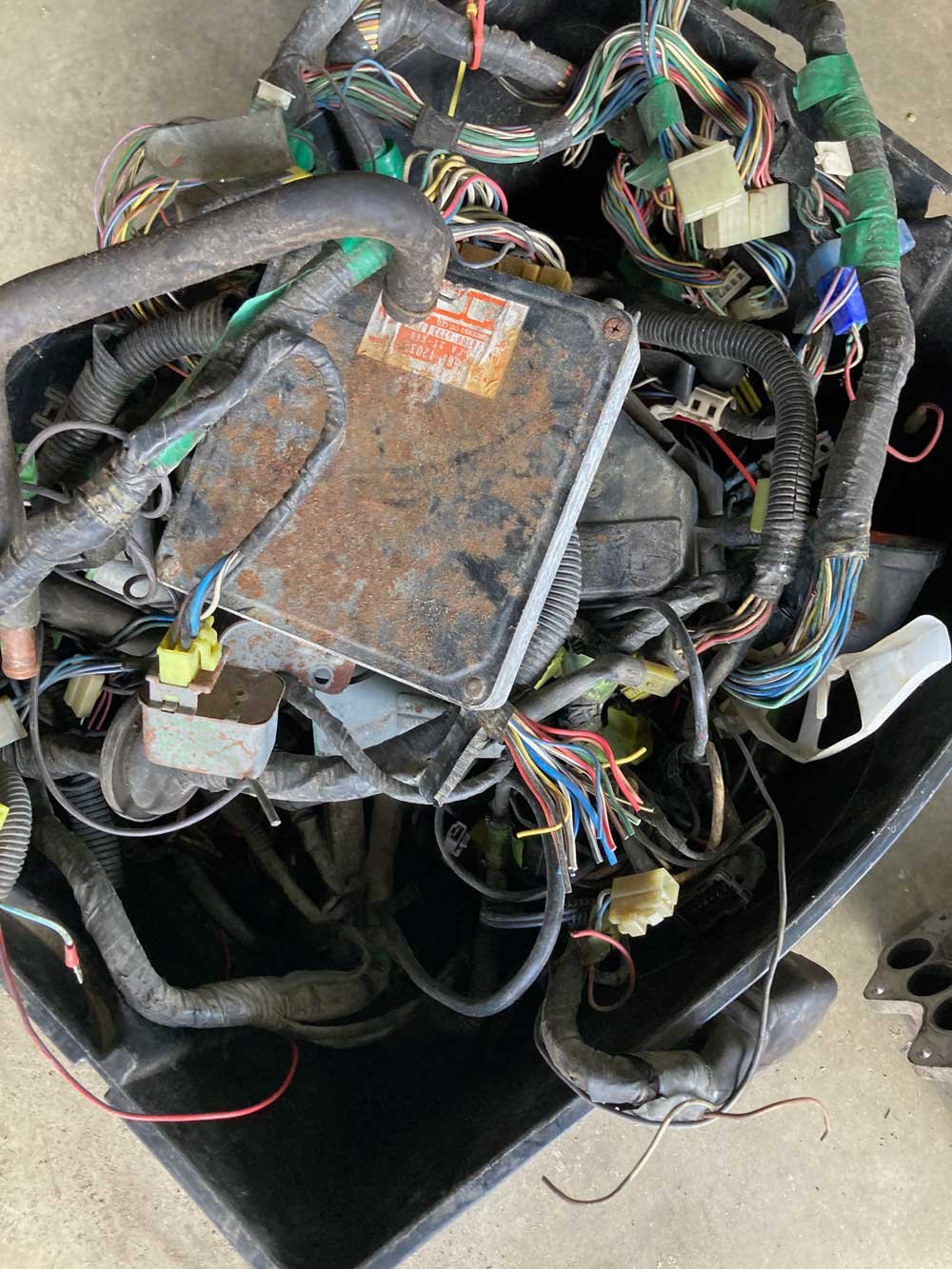
I ended up pulling the whole loom out to check things on the bench. It took a few hours to figure things out, I had made a few mistakes. Since I have pullup resistors on all of the cam angle sensors, the 5v supply on that loom plug splits 4 ways and joins to the signals. However I'd swapped the 5v supply wire with one of the 5v/DI signals on one half of the plug. So looking with a multimeter it still showed the correct amount of resistance on that DI, but, it was the wrong way around. Then I also found a broken wire at the plug end of one of the other DIs. Then I also found one of the pins in one of the plug halves was pushing back out when you put the plug together. So replaced the plug. I've got all of them responding on/off when holding steel against the sensors. While I was there I also changed the supply to 8v instead, hopefully less chance of trigger errors. Hopefully it'll all work okay now.3 points
-
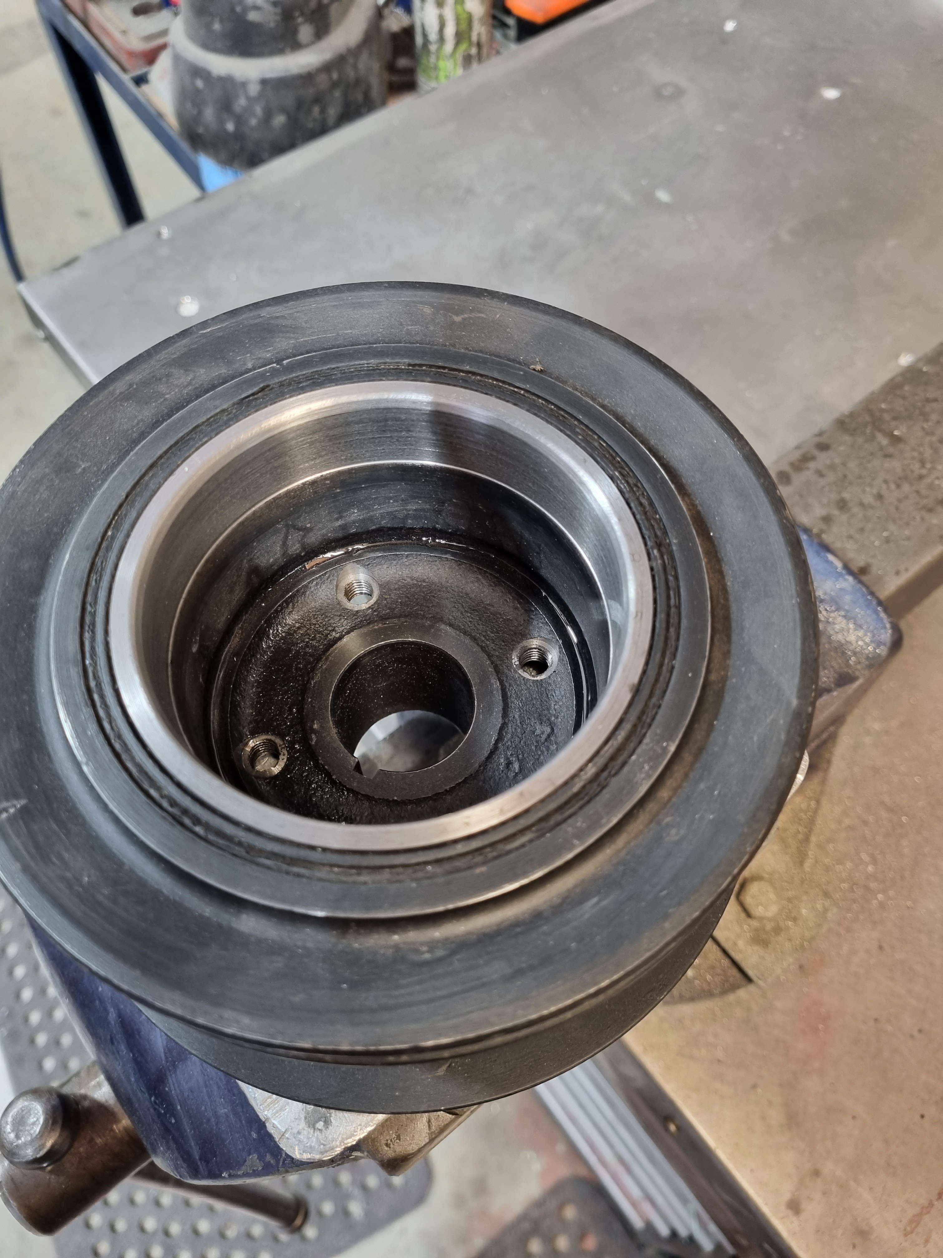
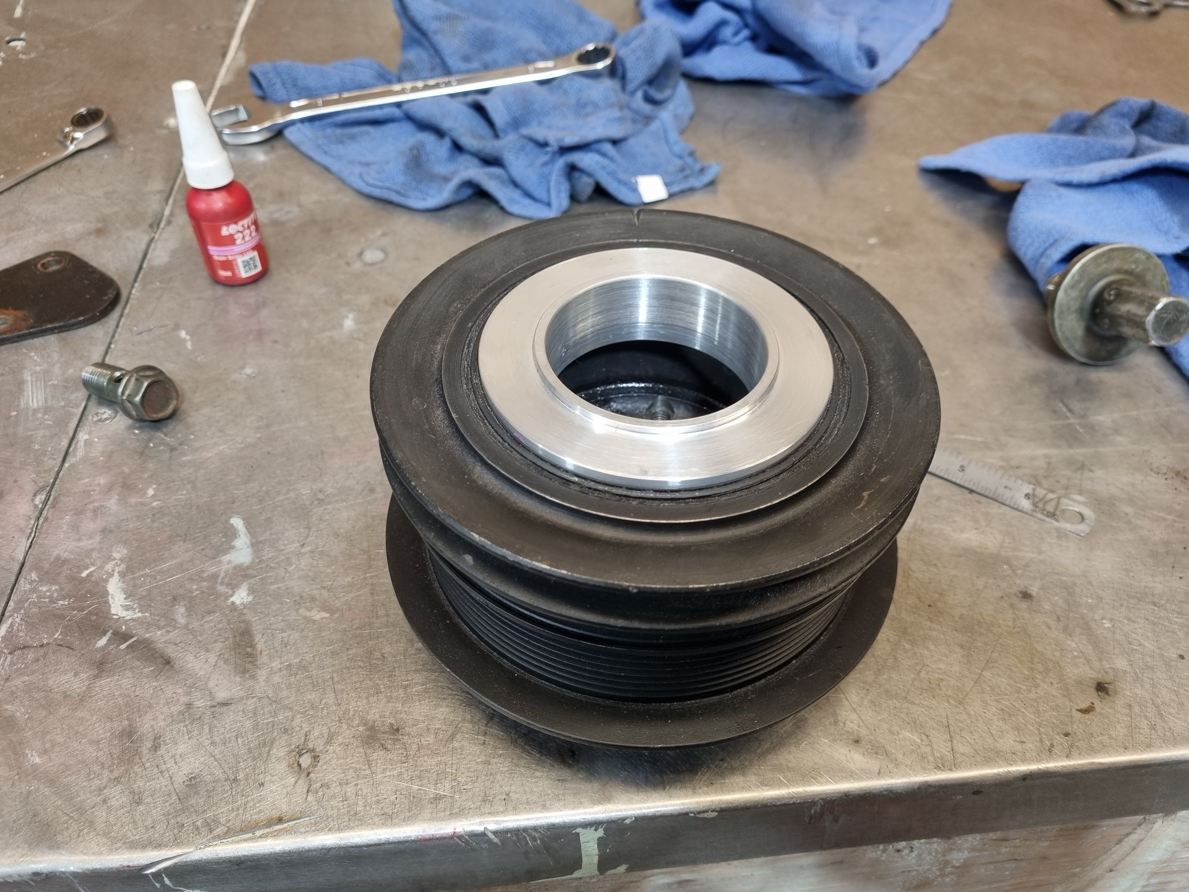
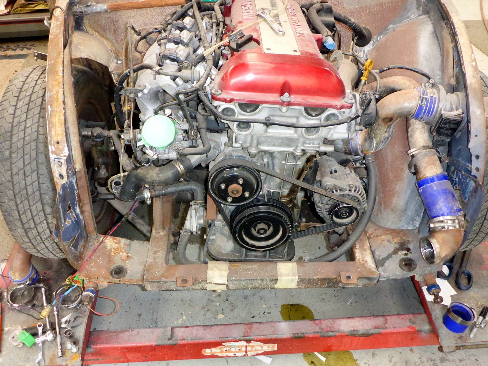
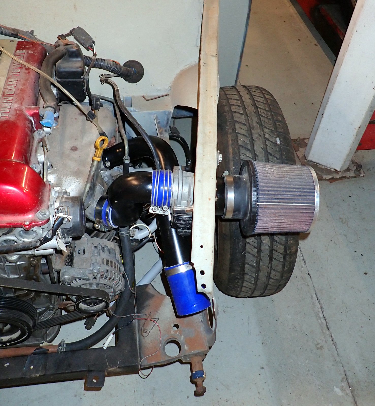
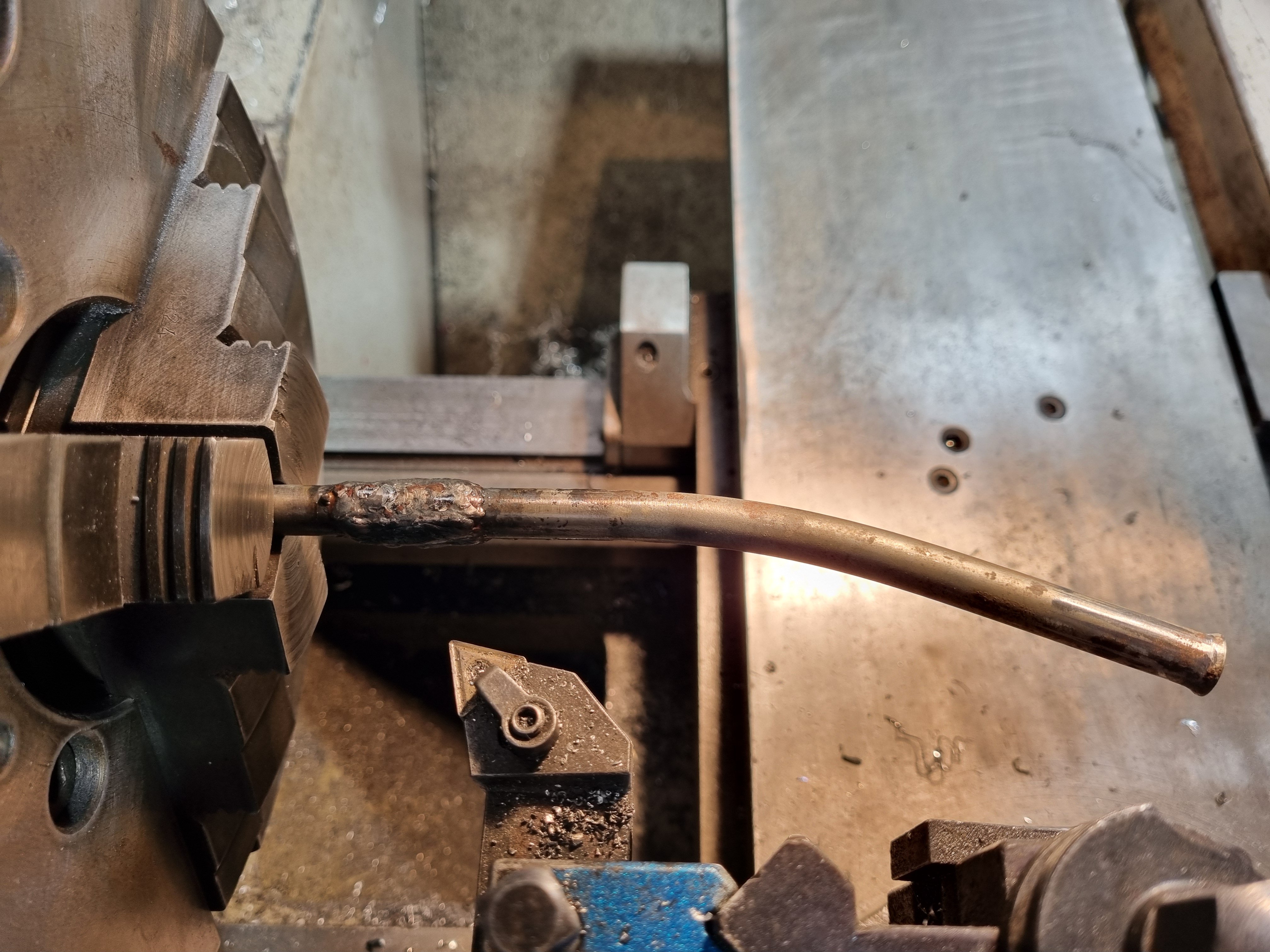
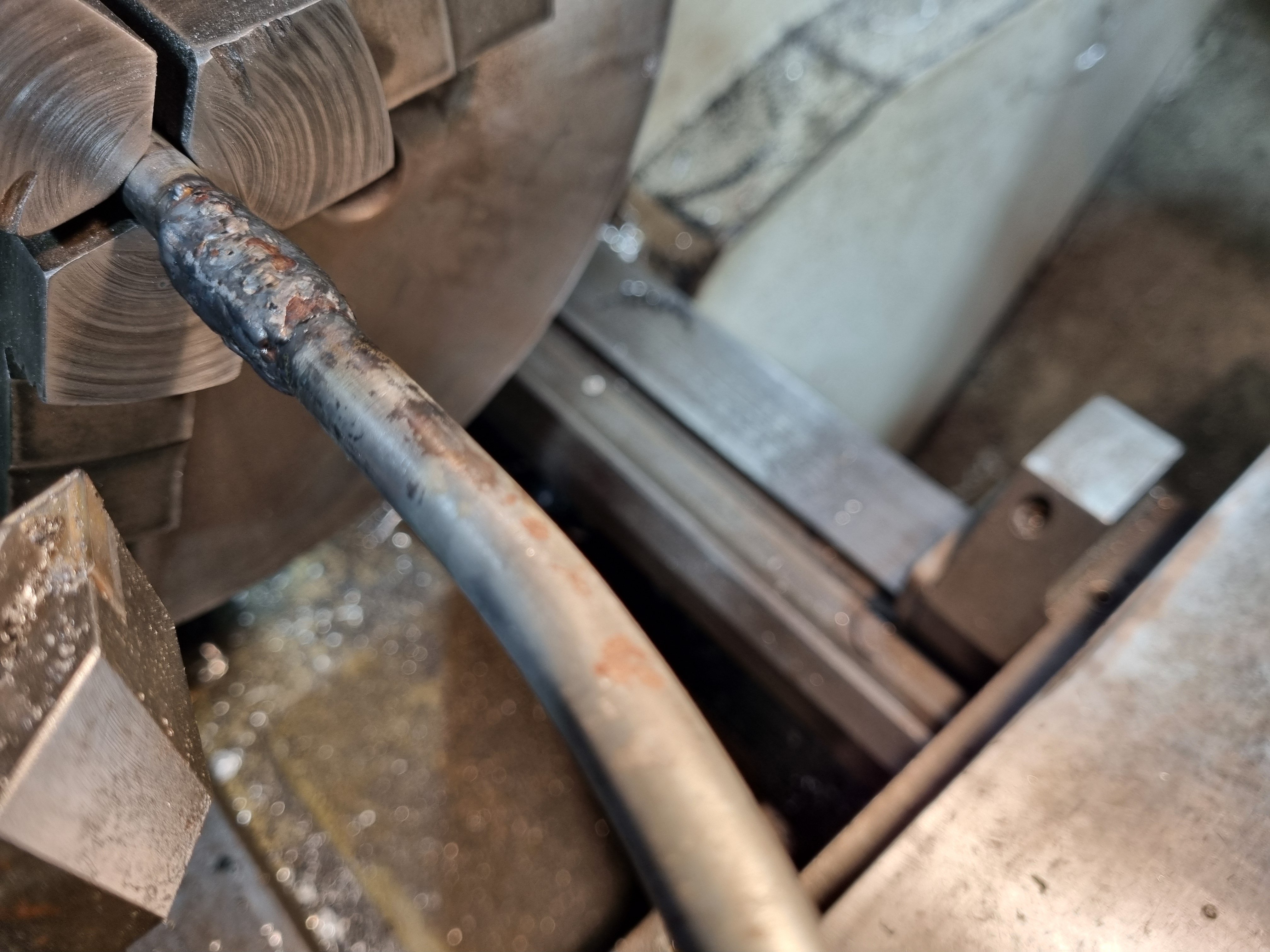
Triggers for the ecu. I couldn't use the stock 5M dizzy because it sits exactly where number 1 throttle needs to be. So after a bit of indecision and fucking around I decided to run a crank angle sensor off the front pulley. I machined the inside of the pulley to an accurate size then I made a boss to press into the pulley. The pulley is cast so I can't weld anything to it. She's a fucking tight fit in the pulley so it ain't going no place. By pressing this hub into the inside is not affected by the rubber isolation layer which can cause erratic triggering. I'll laser cut a trigger wheel and use it to accurately drill 4 mounting holes. Then all I have to do is mount the sensor off the front of the motor somehow.
3 points
-
*girly screams of excitement * just got these through
3 points
-
I hadn't heard of one before. I would gamble on the bellhousing being the same, Mitsi seems to just have the wide and narrow patterns on the early stuff2 points
-
could you maybe make 2 halves from some MDF, then use that to press the shape into aluminium and then weld together, if you get some O state alumimium its very workable...2 points
-
Yeah/Nah/Maybe Not really an easy short answer cos the variables are huge in composite design, more shape complexity just means more nasty tooling design! With CF, rule of thumb, anything under 2mm precision needs post machining, of course with specific part experience and process/tooling/layup development that can be shrunk but this is a safe start for a one-off. If I was making this for you, I would be going for a sheetmetal solution first to get further clarity on air flow requirements, its a dicky subject so before investing in tooling and materials, getting a good idea the plan works (just heavier) is a good start, Aluminium also gives great track day modification options when things don't work out as planned! In one day I could CAD and manufacture both left and right from 0.8mm Al sheet. In one day of design for carbon i'd be lucky to be unloading the first tool from the mill. As for manufacture, not currently sure who would take this on sorry, most of the suppliers I have worked with would want to be making 100s. Technically I have all the gear here to do it, (mould making, vacuum pumps, ovens etc) but the cost might be prohibitive? Are you still WFH? i've got plenty of free time, happy to discuss in depth over a coffee/beer2 points
-
@vivaspeed Lols. Well, when works for you? Otherwise we could be doing this all month2 points
-
Choice of materials just depends on your comfort in fabricating them as such? I think making it out of alloy sheet from a basic wireform is ideal. Once you have the pattern you can flip your sheet to mirror the same on the other side. Keep the alloy section is small as your can get away from otherwise could cause some local cracking.2 points
-
I've designed and had made exactly this from carbon, it can be done and CF is no dearer than the other options, its the tooling, time and consumables that add up... Fiberglass would probably be fine, its the resin system that generally defines service temps, no real structural reason to use carbon over glass either. I love sheetmetal, cheap easy and fast, thats where i'd be leaning as a first off, a diffuser cone to go from the 3d print to feed duct desn't look too hard? Not too hard to CAD, print A3 and then cut out.2 points
-
Very true, good idea on an approach. Sometimes when you racing cars with 500hp the braking zone is the only time you will ever get close to feeling like you can pass them2 points
-
Just use your brakes less you hoon2 points
-
SHIT YES2 points
-
I've got extra outputs on the megasquirt. I could set up a stepper motor to open them at set values. But realistically I'd probably just be opening them at certain times for lol effect. Like outside an oldfolks home at 3am or next to a community hall where there's a workshop for those who suffer from ptsd. Joke. I would not do that.2 points
-
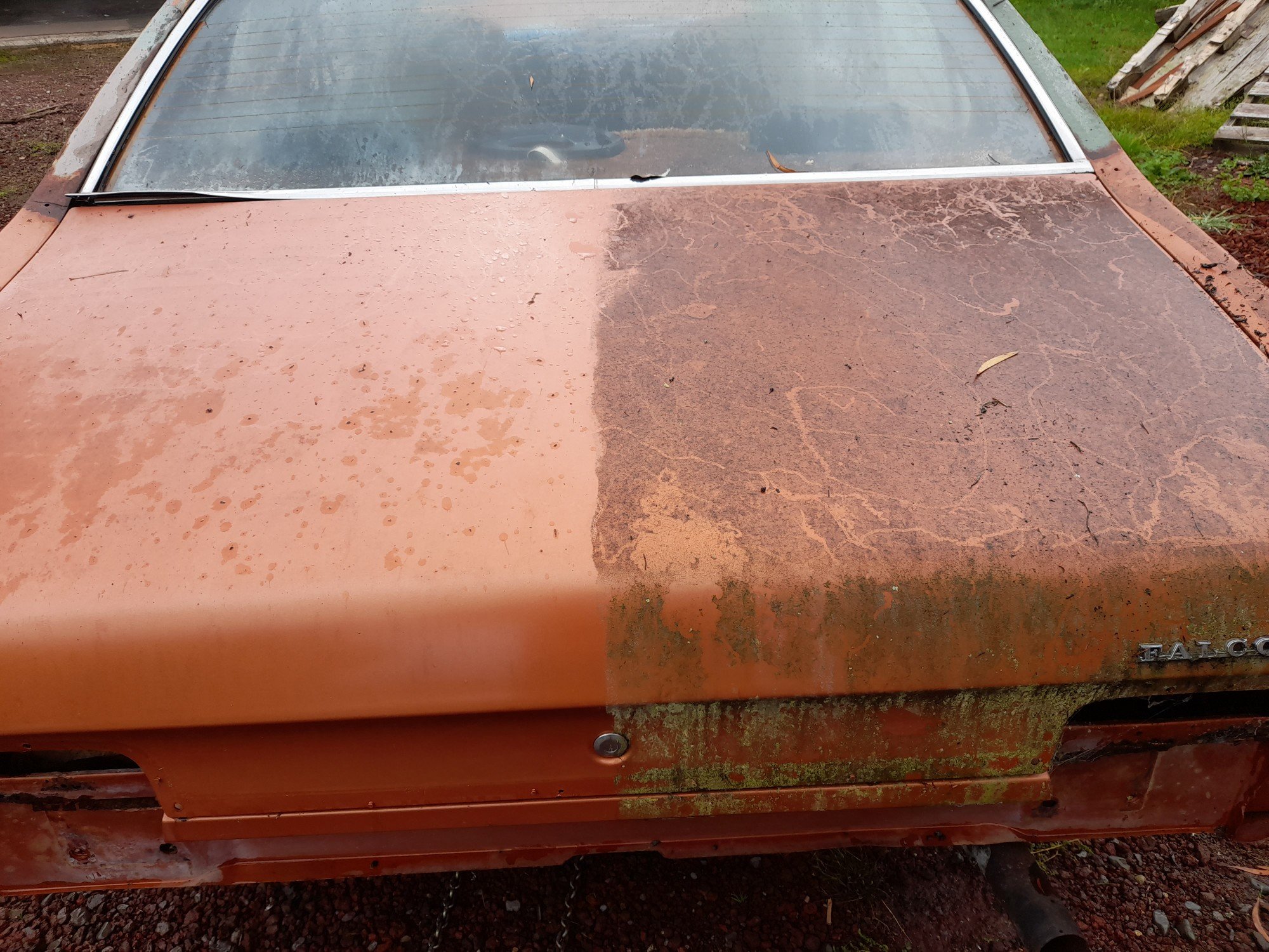
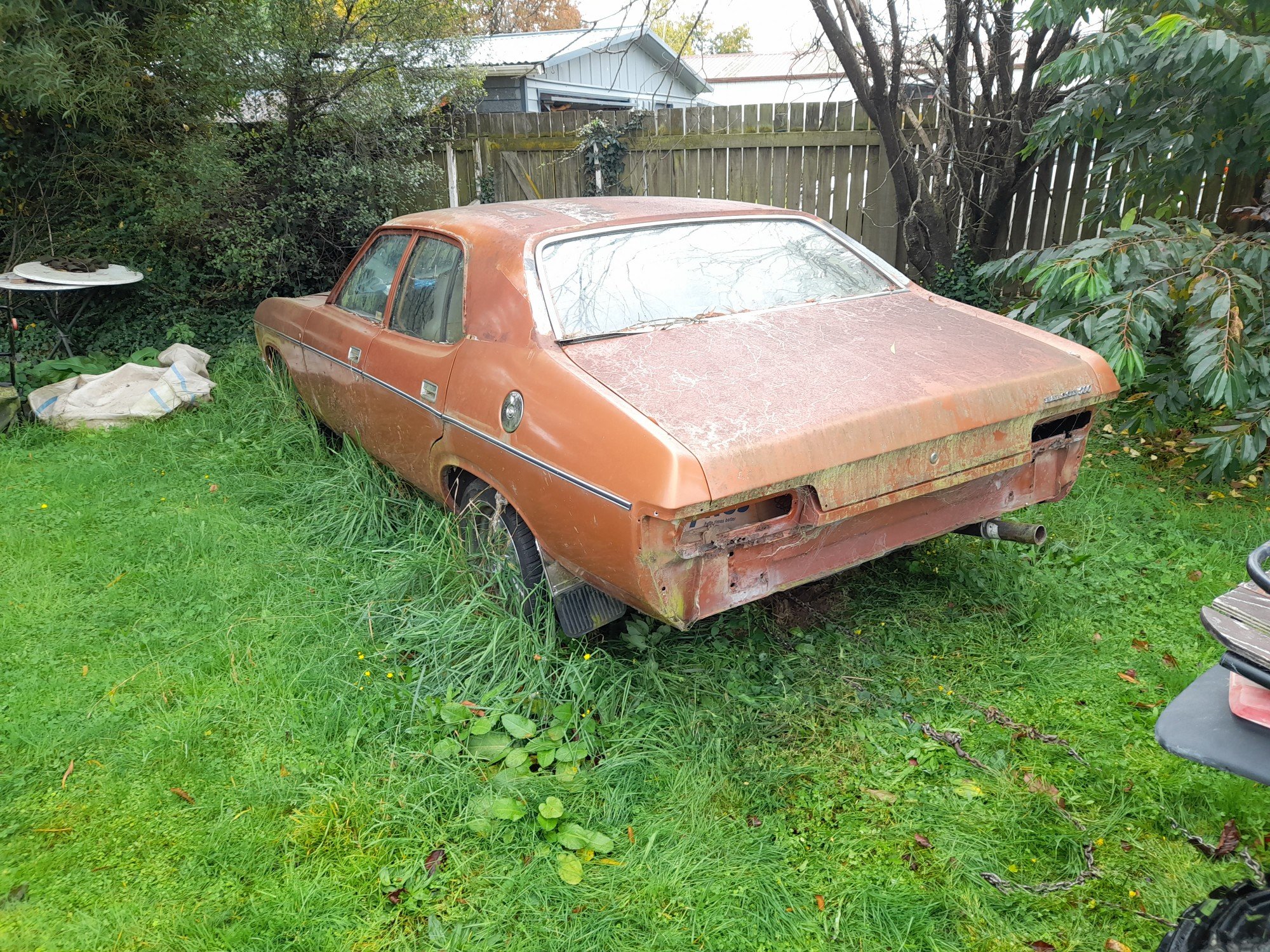
Today went pretty smoothly, managed to solo tow the old girl off the lawn and onto the driveway and waterblast 2 years worth of lichen off. Found lots of cancer had spread but not as bad as it could be. 15 yard test is still a pass. Also found lost of lifting bog from its life before me, will make for interesting times ahead. Had to use the quad with a bare tire on the front to push it into shed as the brakes were binding on, got wife to steer it and it went slowly rolling into the jack, axlestands and compressor. She hops out 'i tried using the brake but it didn't work, its not my fault!!' Calmed her down with 'if i told you it had no brakes would you have hopped in it?' Prolly no dinner for me tonight lol.
2 points
-
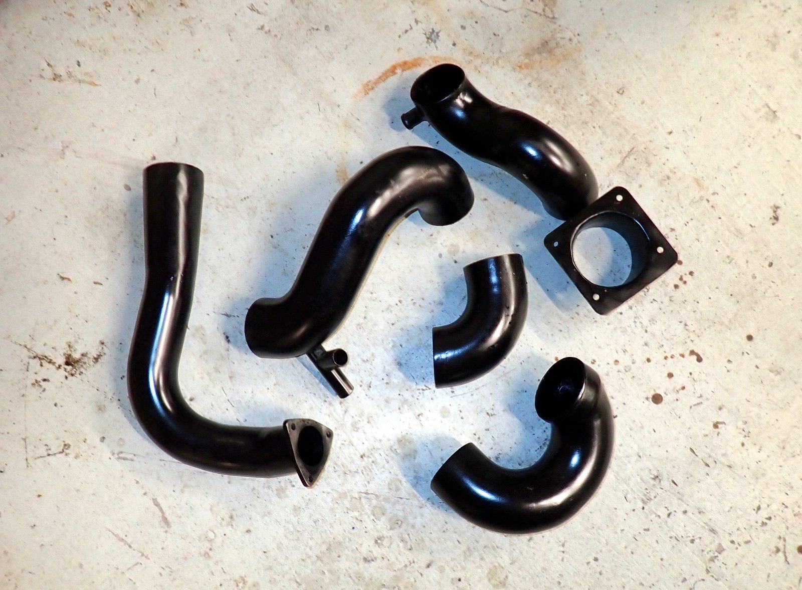
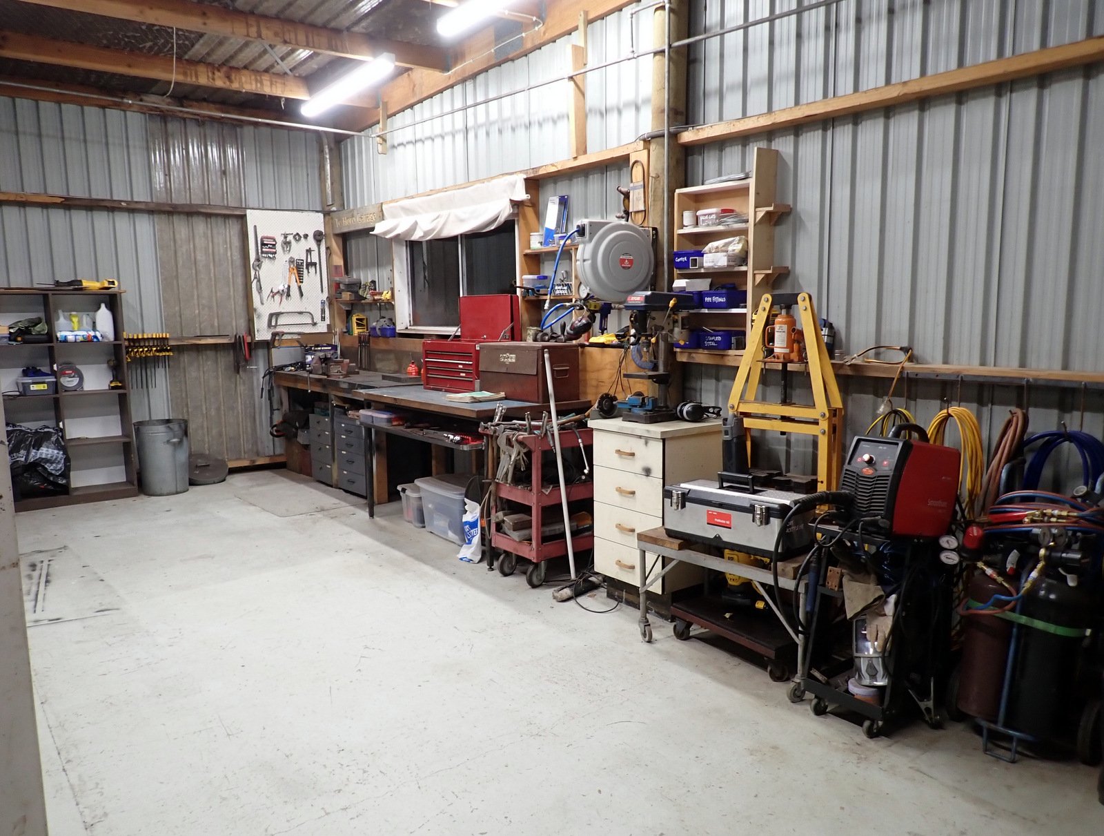
Got some paint on them and baked it with the heater for a while Good thing I have some photos from when I took it apart 7 years ago to refer back to for what goes where. Got one side done, looks better with the pipes painted I must say. Had to stop and tidy up the work area as we have a couple of house viewings tomorrow. I don't usually tidy up until either the stage of the project is finished, or I can't find what I need.
2 points
-
Have reg and coughed up. Not 100% sure on travel arrangements as too many balls in the air right now, but I'll probably need a ride/drive from ChCh.1 point
-
I've done a 3d printed dimple die. We pressed panel steel with just a nut and bolt through the die. Alloy should be much easier than panel steel to work too. It would be a fun CNC project to make up MDF forms1 point
-
One small thing we used to do when I was racing was to move the car (hand push a few hundrend mm) in the pits a few times after each race. Our thinking was the hot calliper reduced heat dissipation from the hoy rotor so if we pushed the car further back into the tent every few minutes after the race the rotor would cool more evenly. I have no idea if that really helped or not though. Ha.1 point
-
That's not what I said, why would doing a 1 year wof check on a 1999 car be any more risky that a 1 year wof check on a 2000 car? Do you actually drive an old car? The 6 month wofs are a pointless waste of time and money.1 point
-
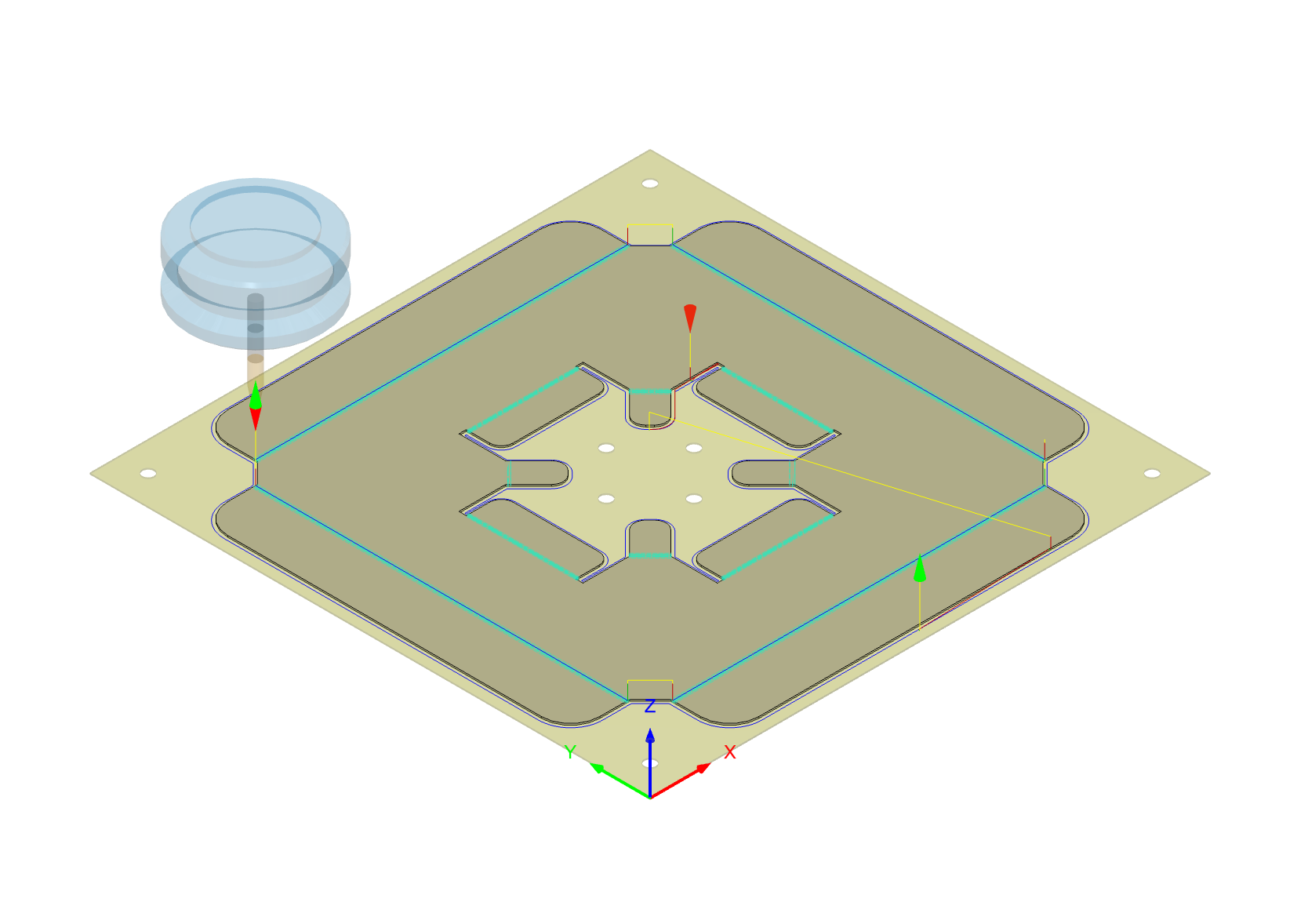
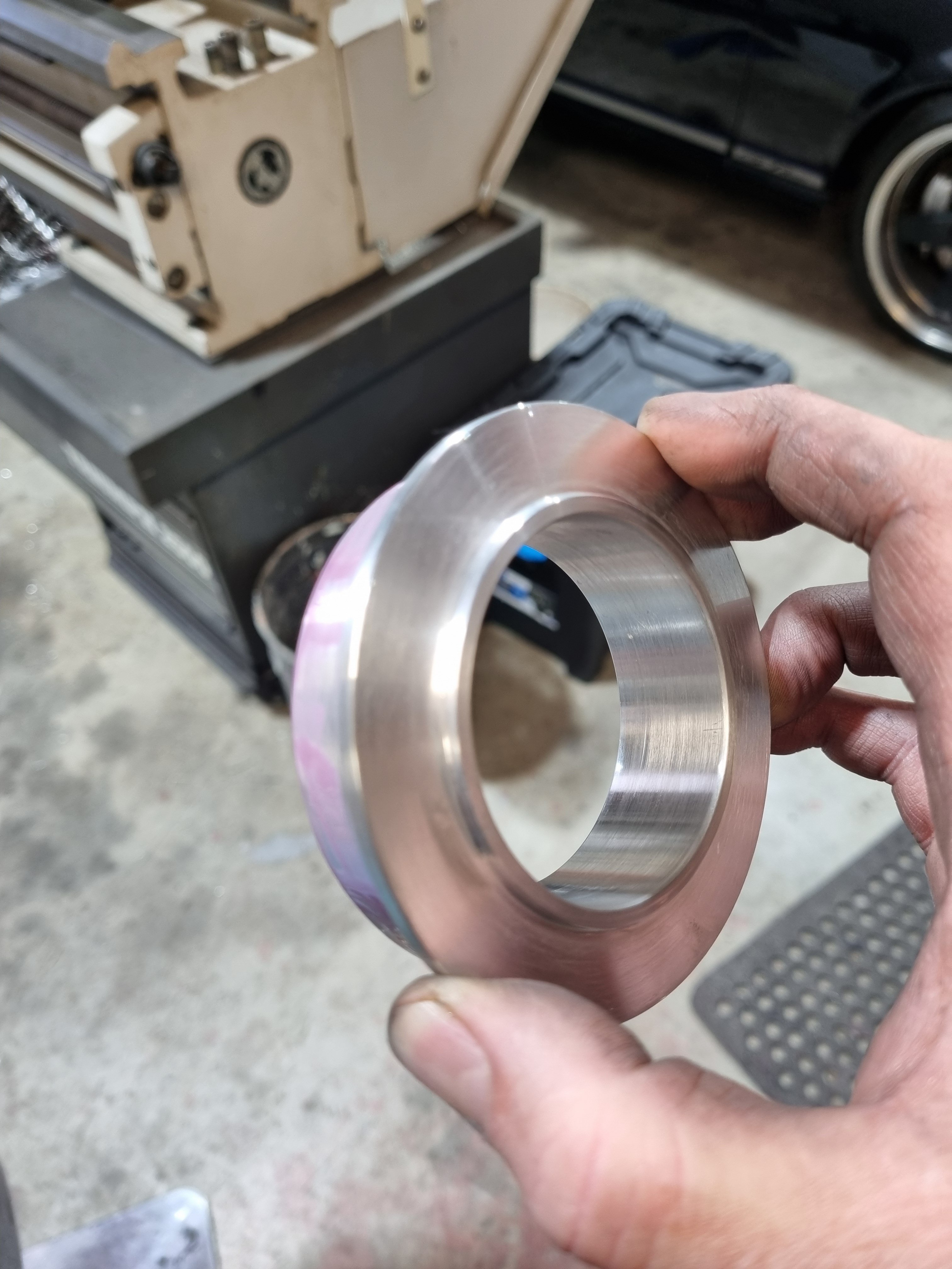
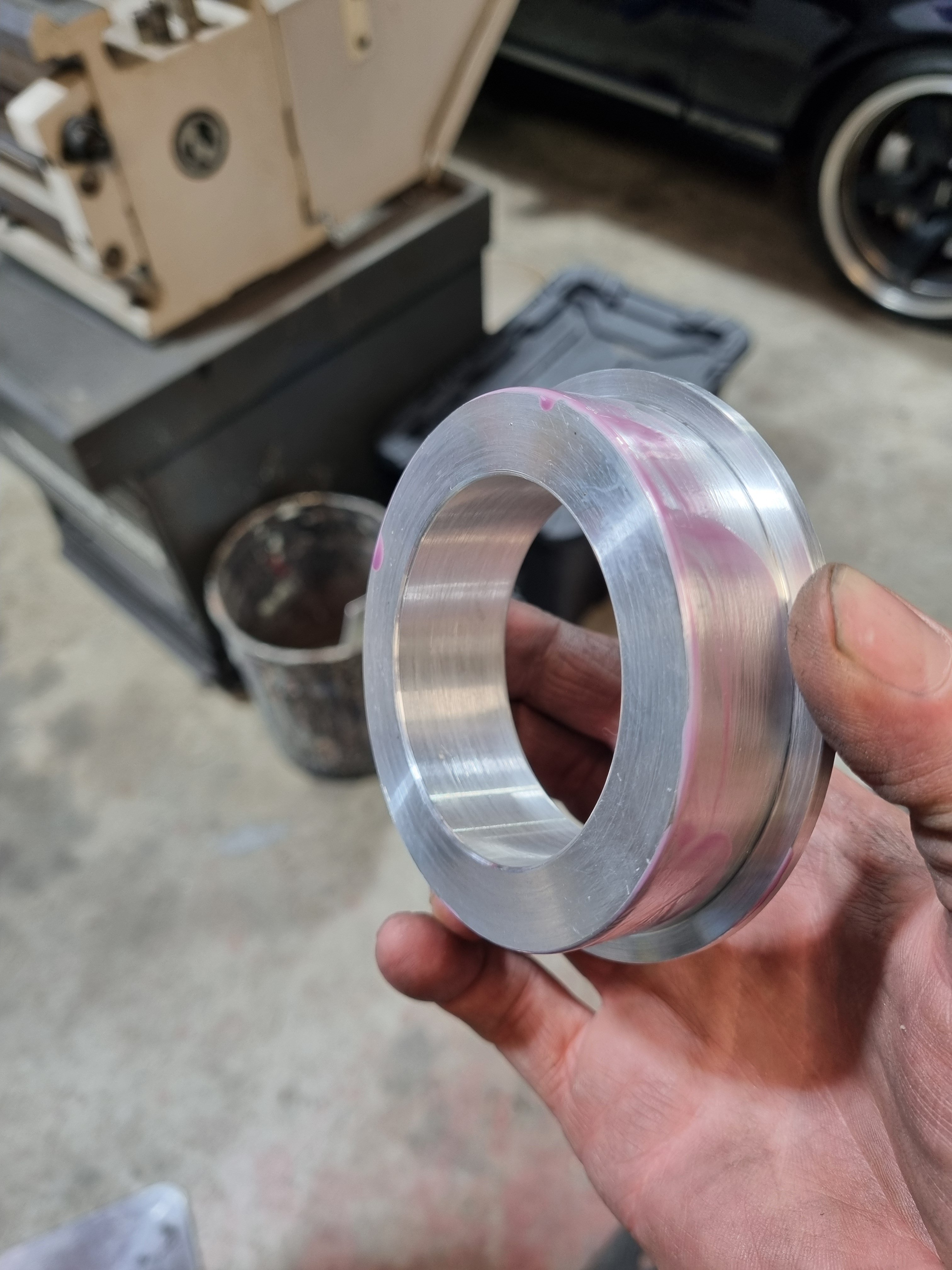
Current hole size is 1500mm2, tube is 2.5" (3100mm2) however the inlet on spoiler is 2" (2000m2) New hole size is 4000m2, I'll be upgrading the tube to 3" (4500mm2) and the inlet to match. If i was 3d printing in metal or maybe doing it carbon fibre it's possible to get the hole on the plate to 4500mm2 but it's a more complicated shape. So i really do need to increase the hole size, no room internally in the rotor for vanes, only have less than 20mm to play with and there is bolt heads in there as well. also don't think it would help, i need to get air into the center of the rotor and let the rotor vanes then pull it out. I'm already running maximum disk size you can in a 13" wheel. there is 2mm of clearance between caliper and rim, to go thicker would require new calipers and going to larger rim. Background: I'm warping rotors as the hats have not been designed large enough and so the air is going straight through and up the outside face of the rotor, I have a solution for that, but that means any air will escape where this plate sit, and that means there will be cool air flowing over one face of the rotor, creating a temperature differential which will cause them to warp again. At $600 per rotor I can't afford to warp another set (If i can get temperatures into the correct zone they will last many years), so I have to make sure the air goes out the vanes evenly, hence the tight fit, but then I need to ensure enough air gets in, and larger is better in every way as you can always blank off the inlet. I also only want to do this once, so prepared to spend time/money getting it right.1 point
-
Might help to make a wireframe buck/template first. Can do it with tig wire or gas welding 'panel' wire. Bend the wire to the shape you want, tape/tack weld them togethor, then you can lay paper over in sections to transfer onto Ali sheet.1 point
-
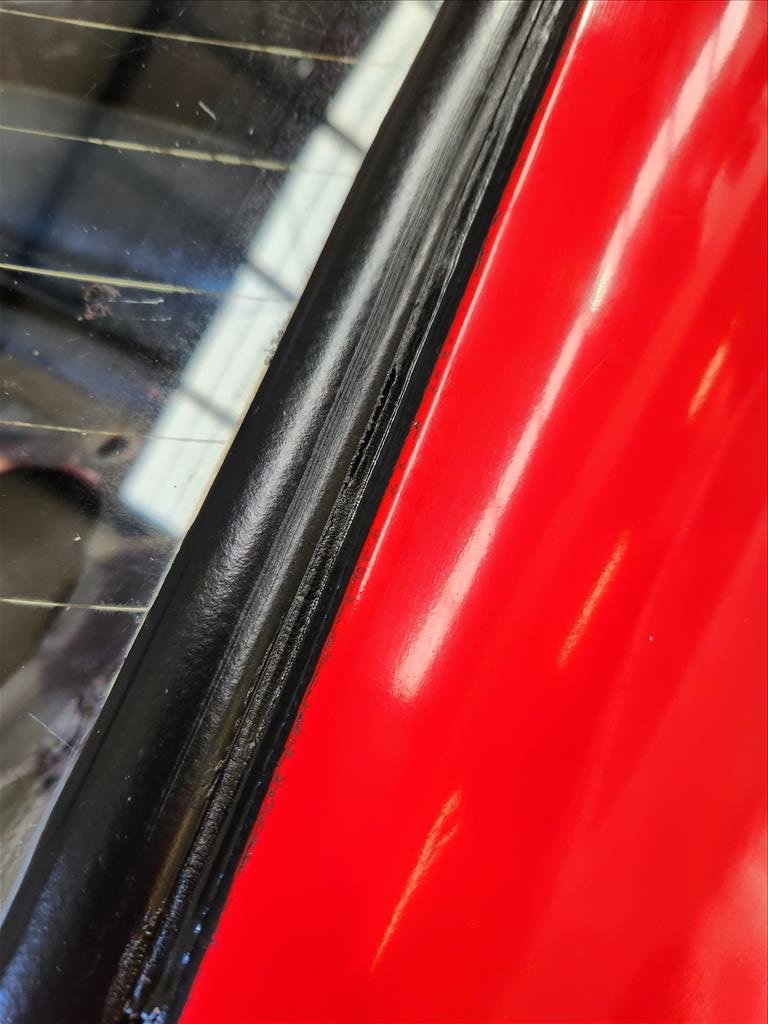
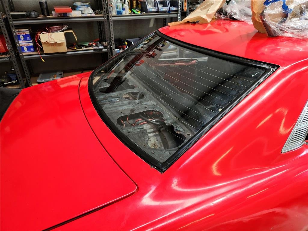
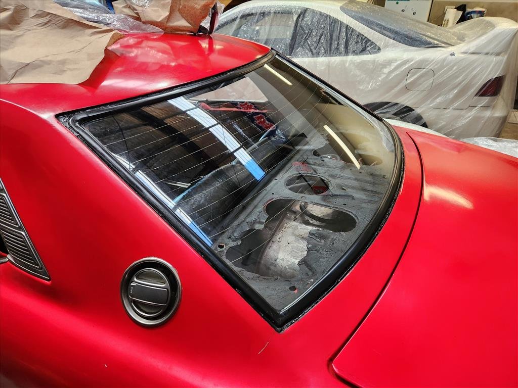
OK last post about painting trims. This time I did the rear but it didn't turn out as good as the front I don't think. I had to get some new tape and I think this tape is probably shit (it is because I got the cheapest one) and it let a bit of the paint bleed through the edges. I tried to rub some of it off with isopropyl and solvents but it ended up just rubbing the paint off as well. Same problem with using a blade, the paint is so bad the blade just sliced it. Then I thought about it and figured it was dumb to stress about these little bits when you look at how the rest of the car looks anyway haha. 10 footer with an instagram filter all day.
1 point
-
@Mourning Cupcake sorry that's no good. Have got a car launch to go to that night.1 point
-
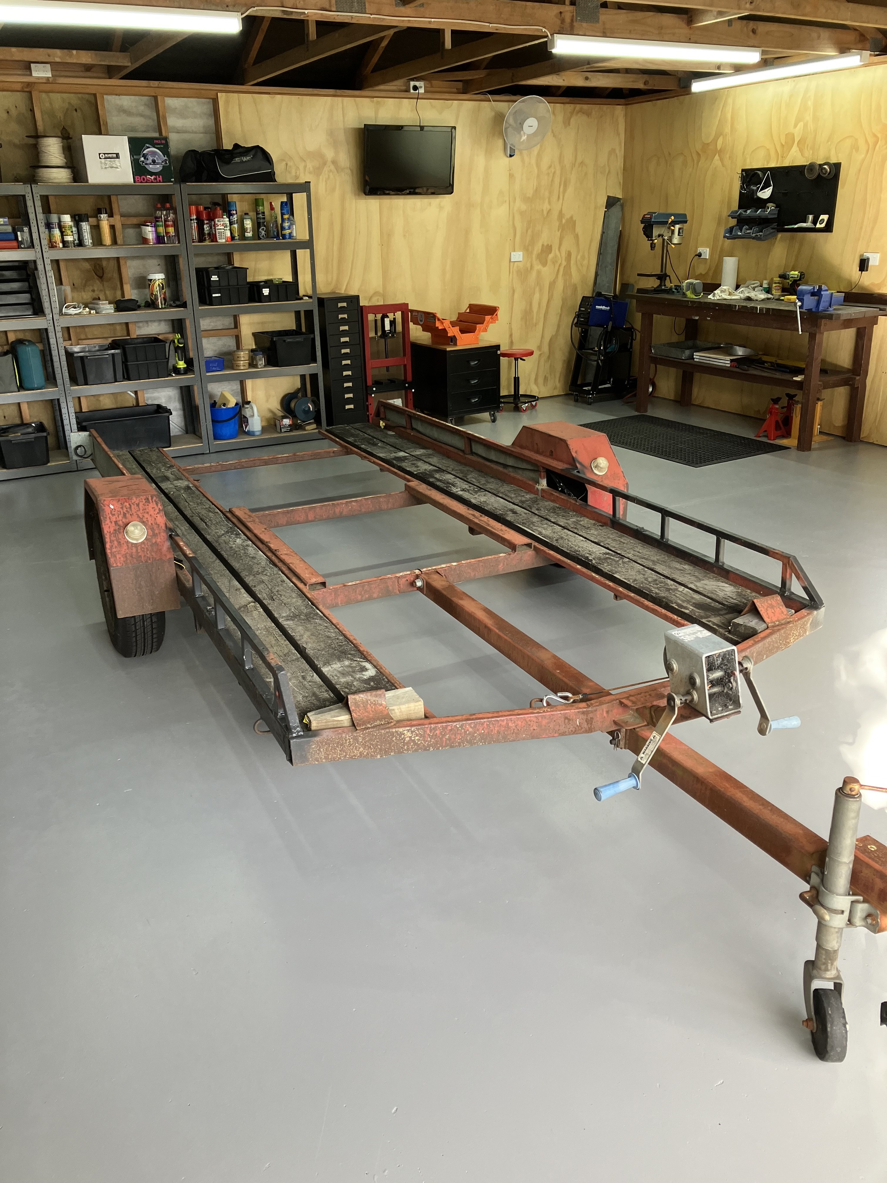
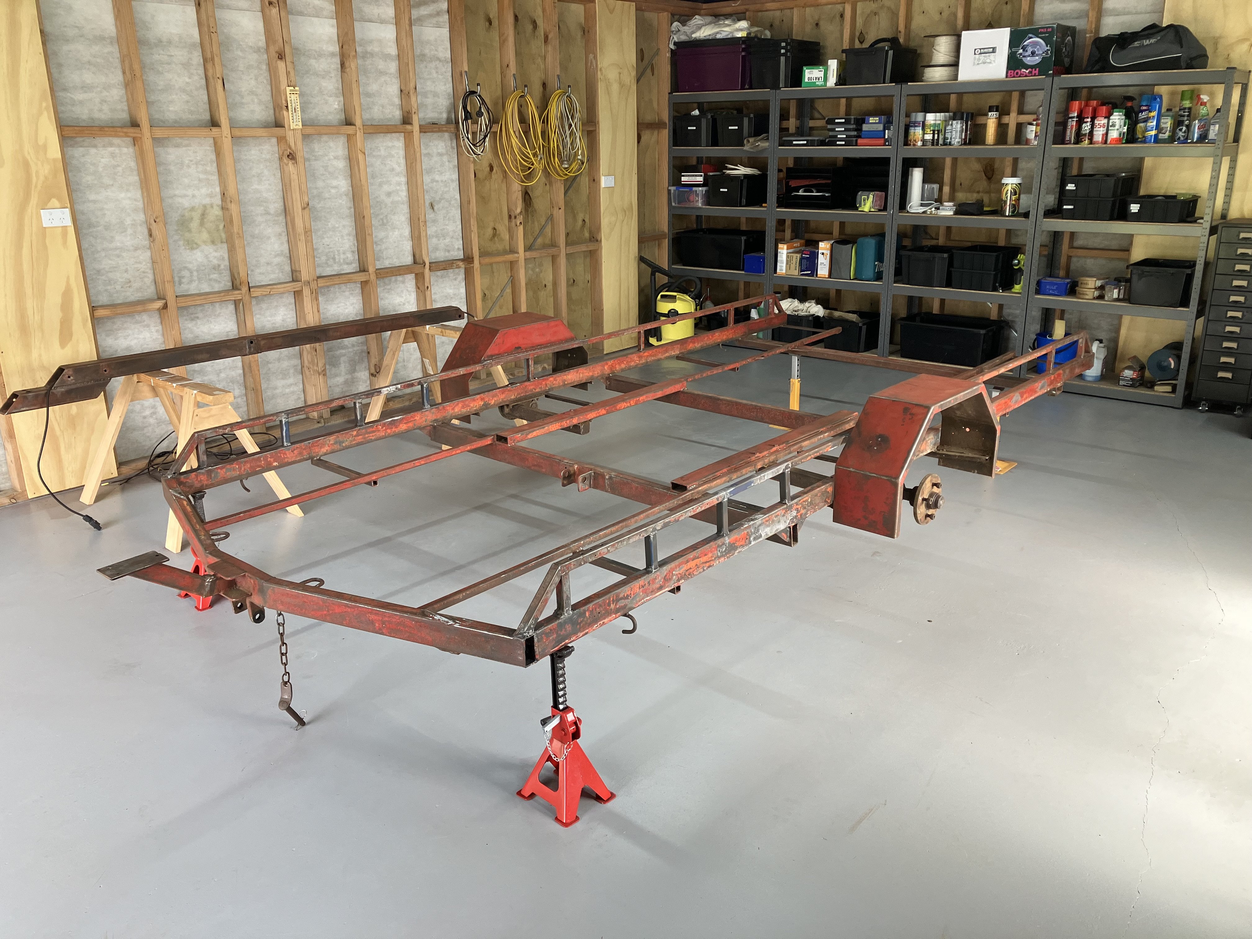
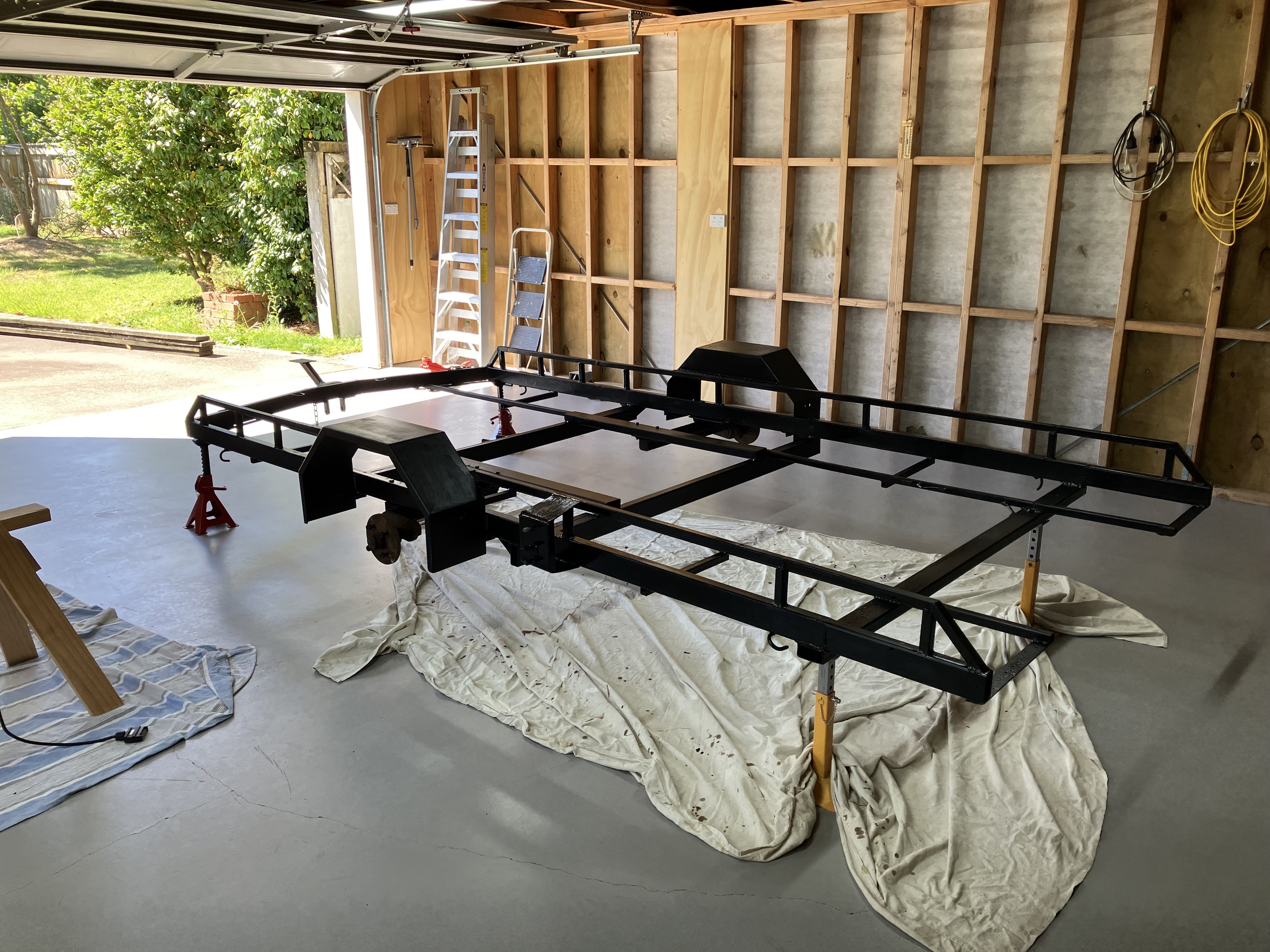
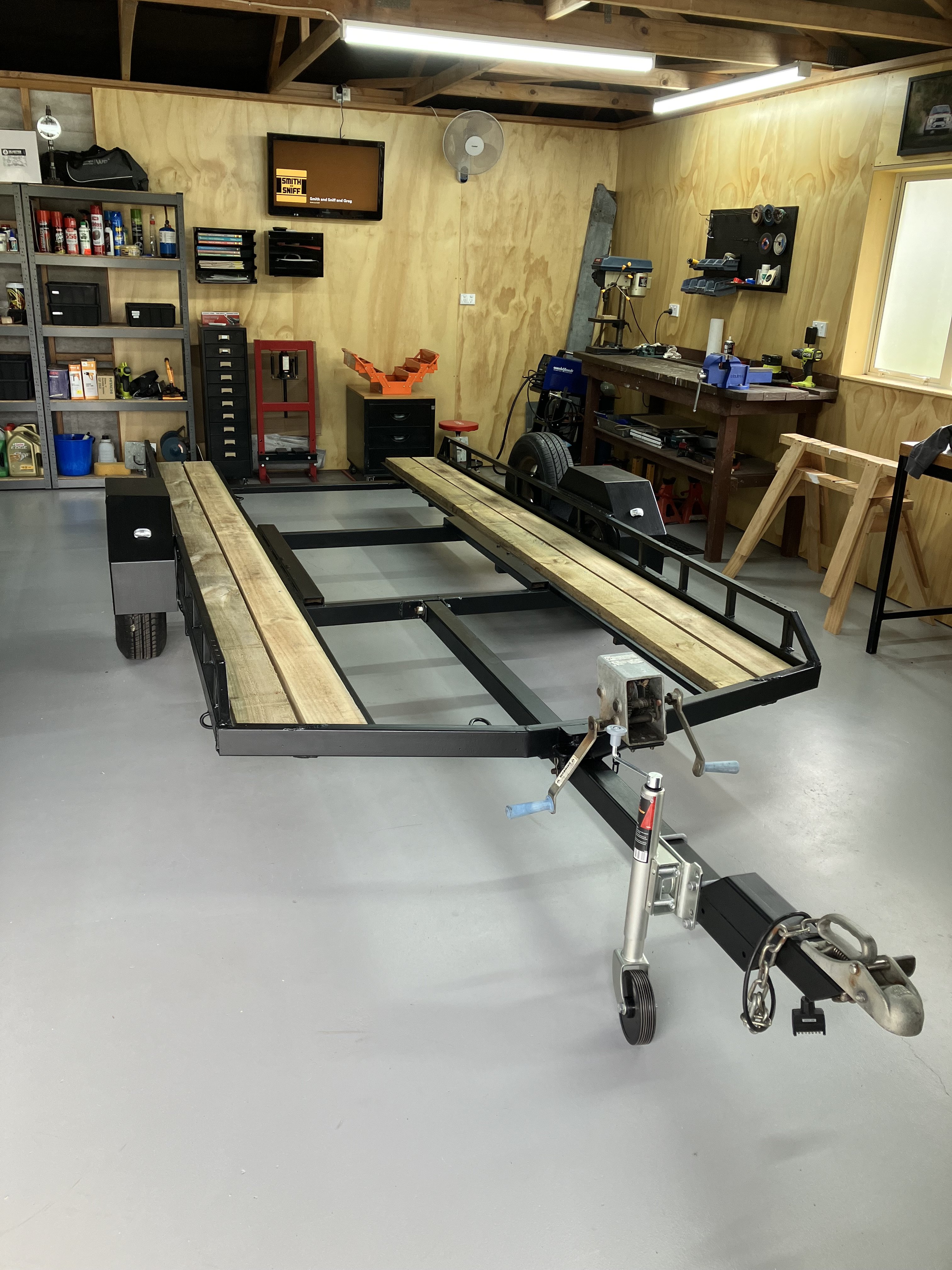
This is kind of random project thread worthy. So I’ve owned this old single axle car transporter for over 20 years (apart from a short period where a mate owned it, then I bought it back). In about 2005 I gave it a rough wire brush and painted it tractor red and put a new timber deck on it (necessitated by a mates Fiat 131R almost falling through the rotten old deck). I’ve been meaning to give it a refurb for ages, but it kept passing wofs and just looked like shit. It progressively got worse until @azzurro borrowed it and it had some structural failures where the spare wheel mounted (coincidentally while also towing a Fiat on it). He kindly patched it up before returning it but it needed attention. After moving back up north I decided it was time to tackle it and strip it right down and give it a birthday. Fix a few bad welds. Paint, new electrics, new deck etc. Anyway. After a few solid weekends of work it’s just like a new one. P.S. if you want to buy it, hit me up. It’s only small (suit Viva, 1200, Escort, Starlet etc).
1 point
-
The spark plug cover? I'm missing one of those. Seem like hens dicks to find too1 point
-
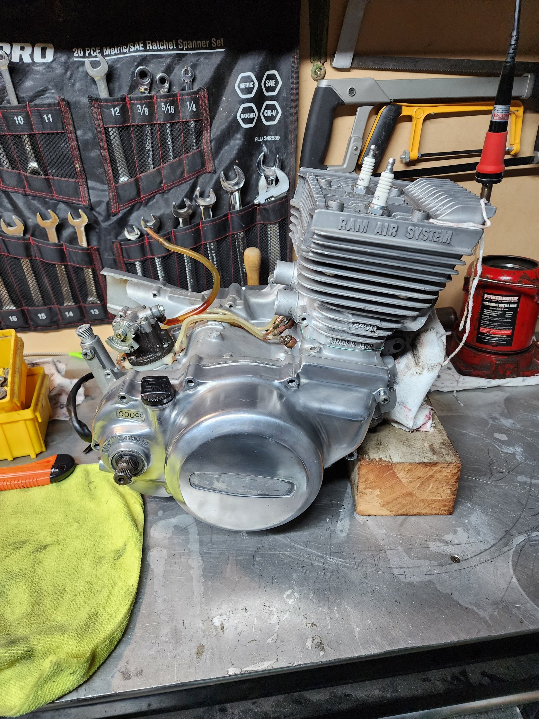
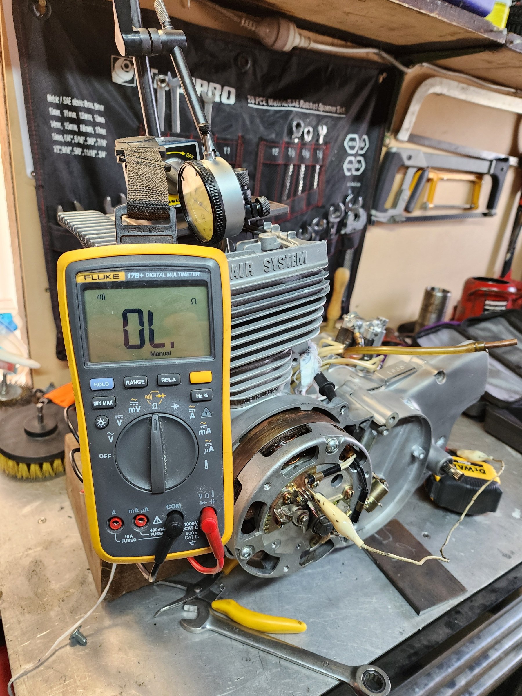
Slowly putting the GT125 back together. Built a 20t big bench top press to do the crank, all the cheaper presses I looked at were poxy piles of shit. And of course I didn't take pics once I finished it Ignition timing set. Just finishing off getting the right surface finish on the side covers, it's kinda half ass polished in all the pics and how the bike arrived. So keeping it that way. New old stock emblems coming for the covers. Cases all glass blasted and re-treated, pretty chuffed with how they look. Now on to the carbs, need to remember to order the intake gasket thingymabobs from somewhere, strange wee carbs the VM18s. The resin/phenolic spacer inside the bore is not listed in the Suzuki parts book, but it looks like you can get a newer and much sexier alternative nowadays. So my final hurdle is, some parts of the frame aren't super tidy but it is original paint. I'll have to see how the OCD vs originality battle goes once I put the engine in
1 point
-
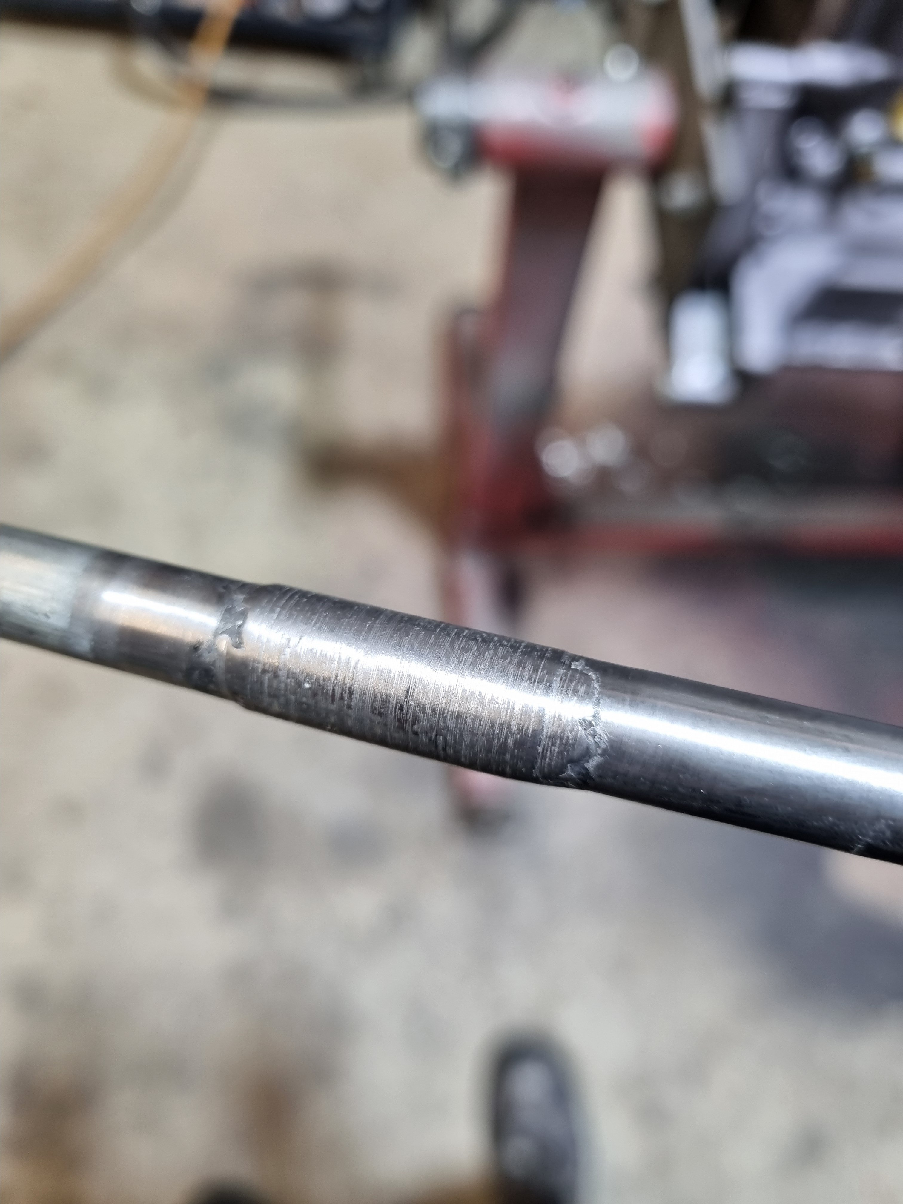
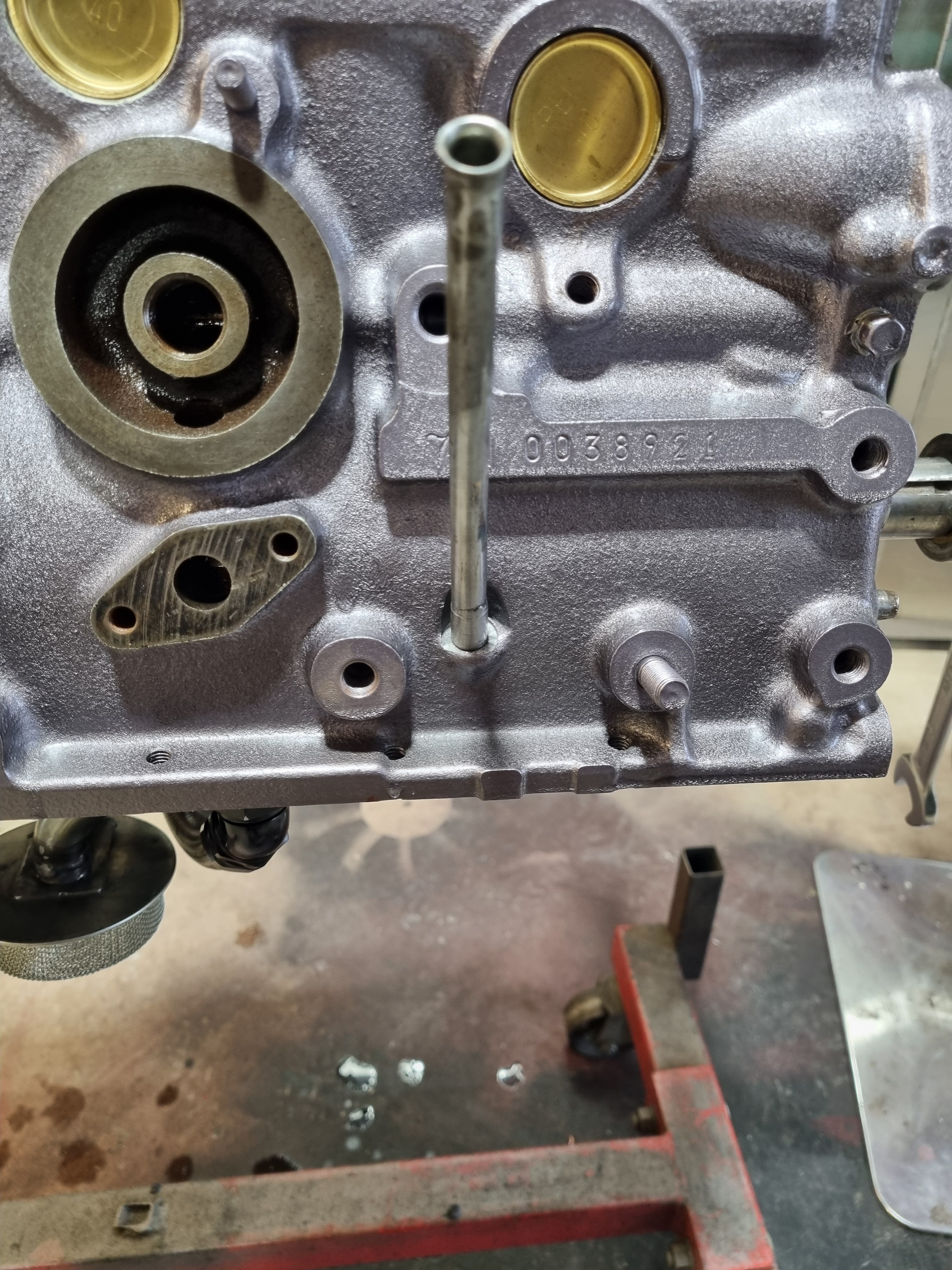
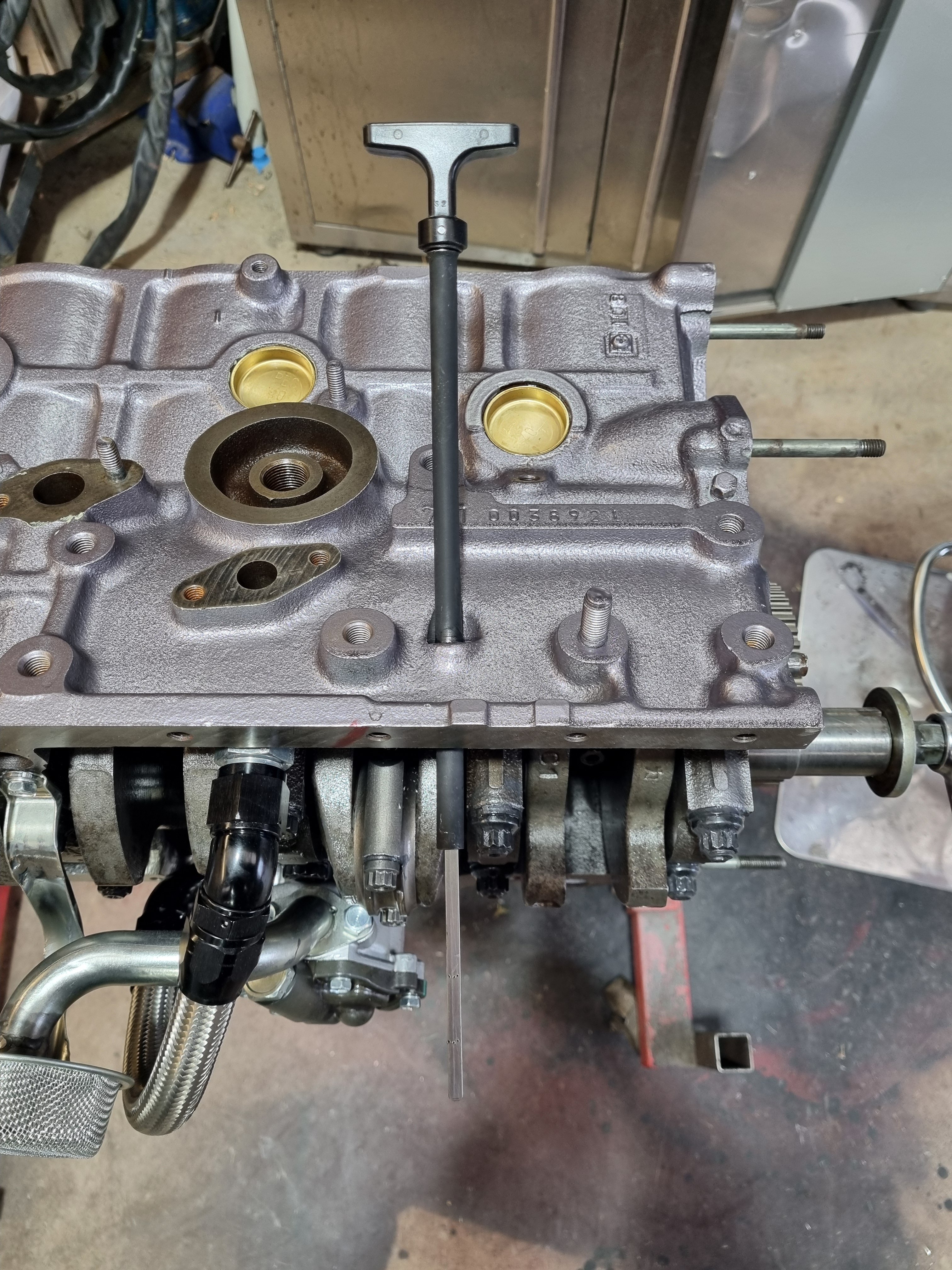
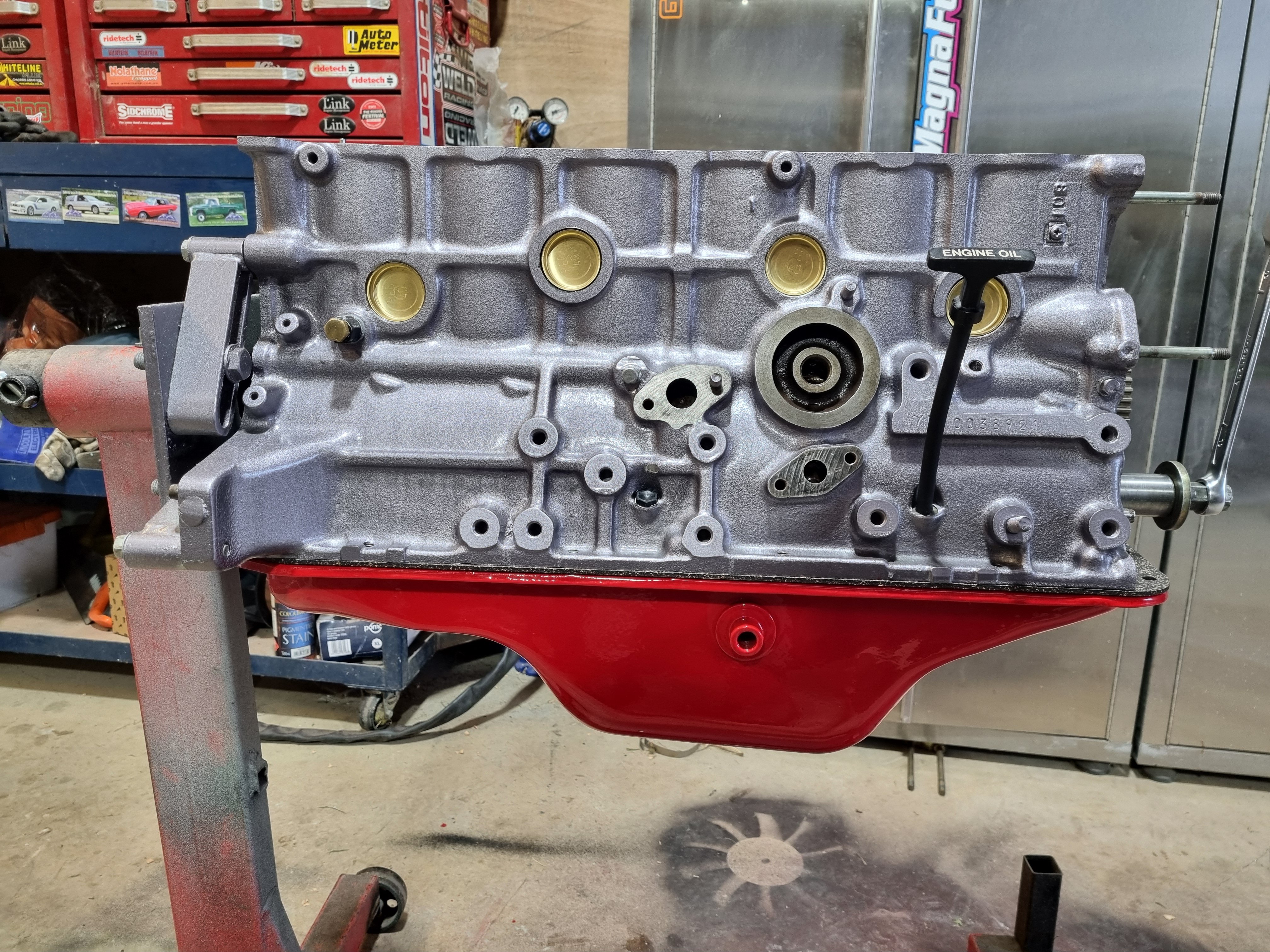
Dipstick. I didn't have one with the engine parts and I had to move the location. The 7M Dipstick location is right where the 4M engine mount goes so I had to drill another hole in the block. No drama the boss is cast into the block, just had to drill it. Then I set about modifying a jz Dipstick tube to work. I drilled the hole to big for the jz tube so I had to weld it to build it up then machine it to size. I fluked the size and got it perfect, its a good tap in fit. I cut the stick to length and used the 4m in the crown to get the oil level marks right. Then I put the sump on, probably not for the final time but it's on.
1 point
-
Fuck that off with a sharp stick. I would never inflict that kind of pain on any individual looking to aggressively sharn and relax, I make dumb decisions, but I’m not a cunt1 point
-
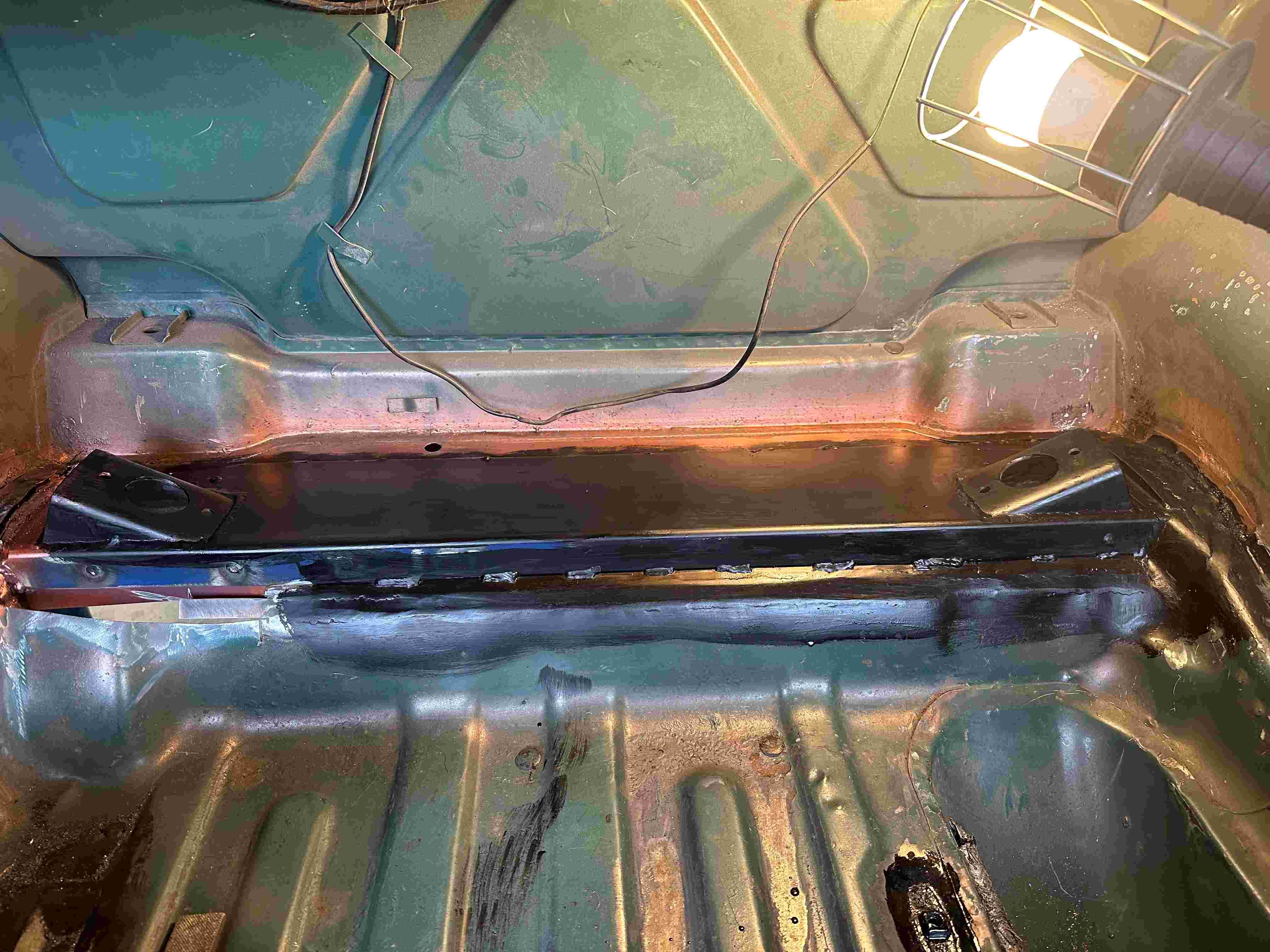
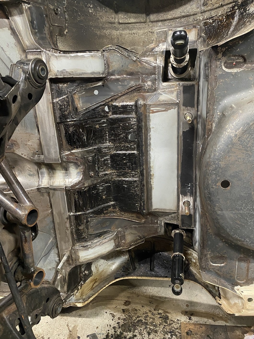
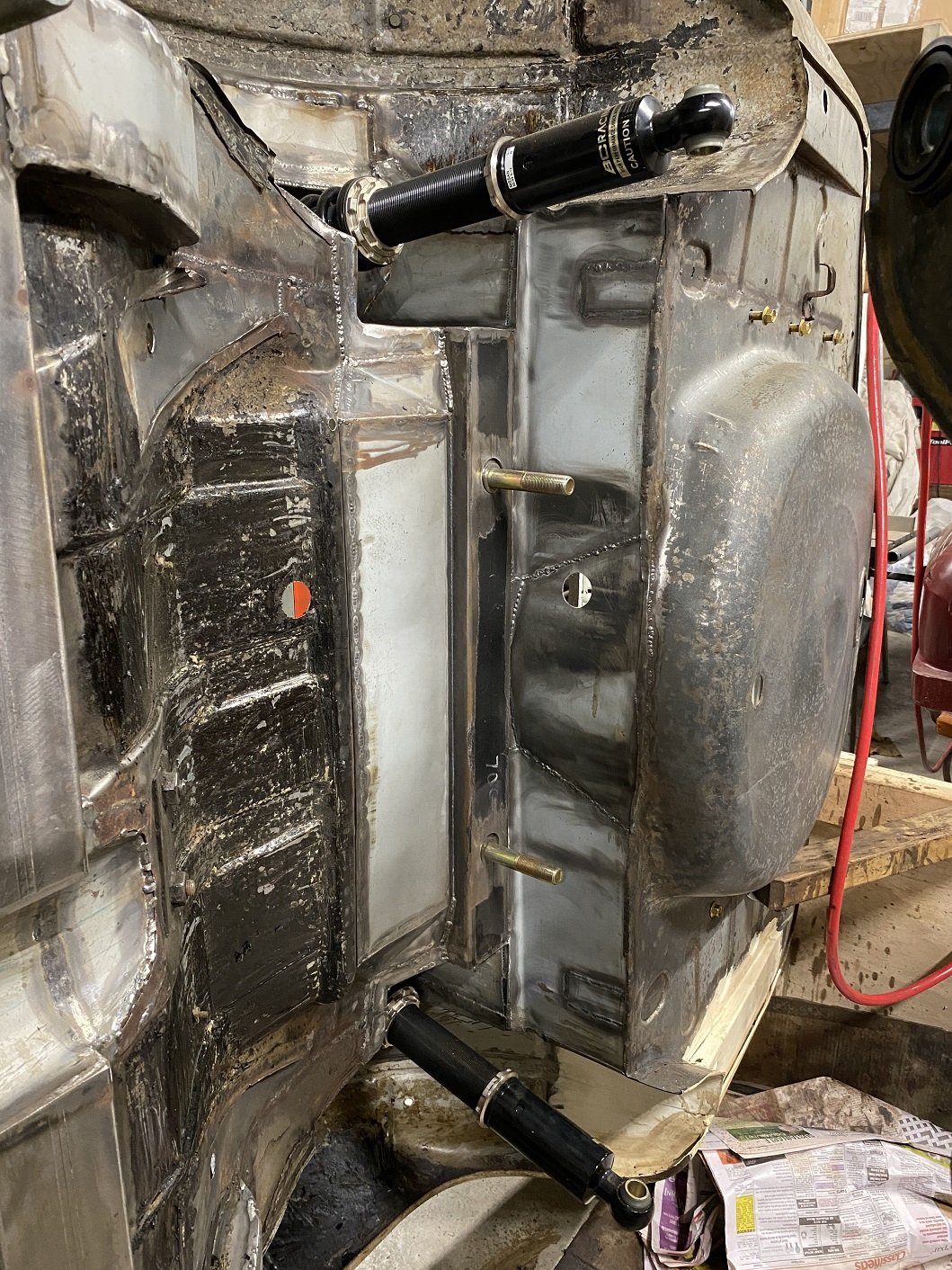
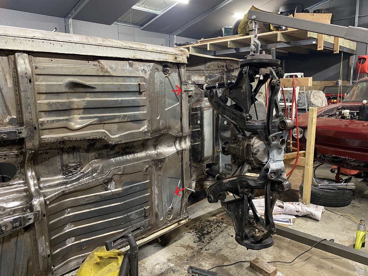
I lifted the rear subframe off. Feels like one of those photos showing off the big fish I caught... With the car like this it made it really easy to measure between the front and rear lower ball joints to find the wheelbase on the drivers side was longer than the passenger side. I suspect it's because I built the alignment jig for the two front mounts on the yellow car, not this one. I had oversized the holes that the studs come through to allow some wiggle room, but I need to take a further 4mm off both sides. Once I can get it on a wheel alignment machine to make sure it's straight the studs will get welded in solid. I've started cleaning off the last of the underseal. I've got to also remove the remains of the original spring seat reinforcement.
1 point
-
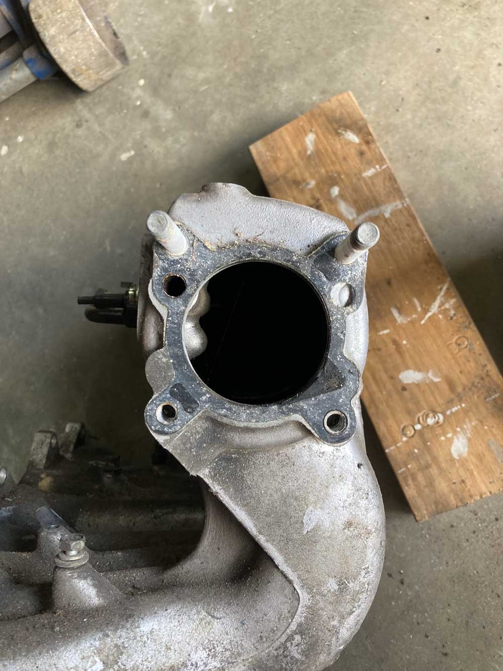
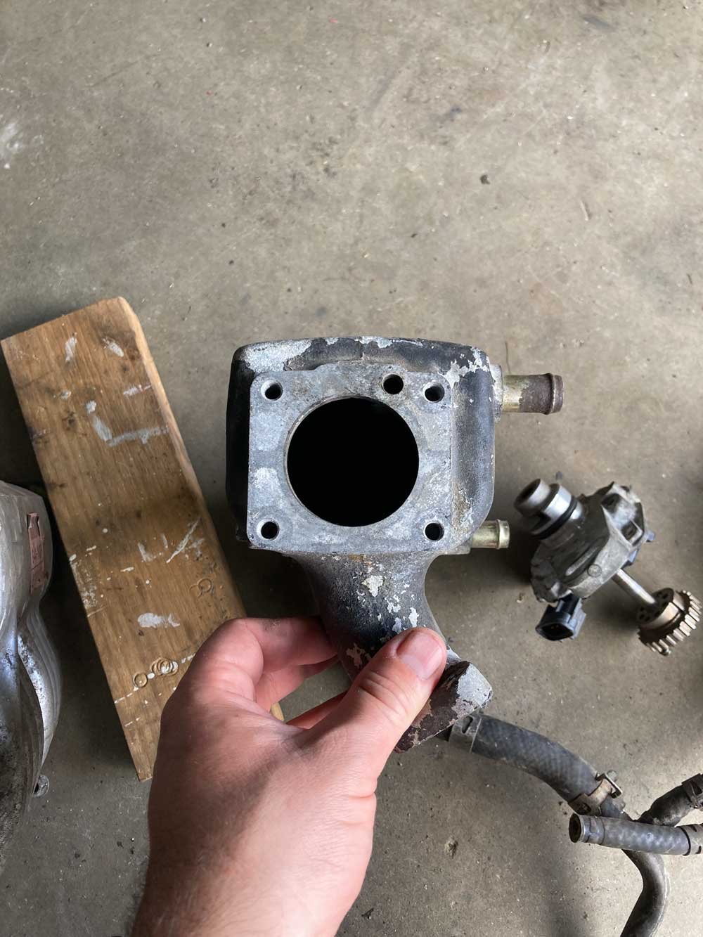
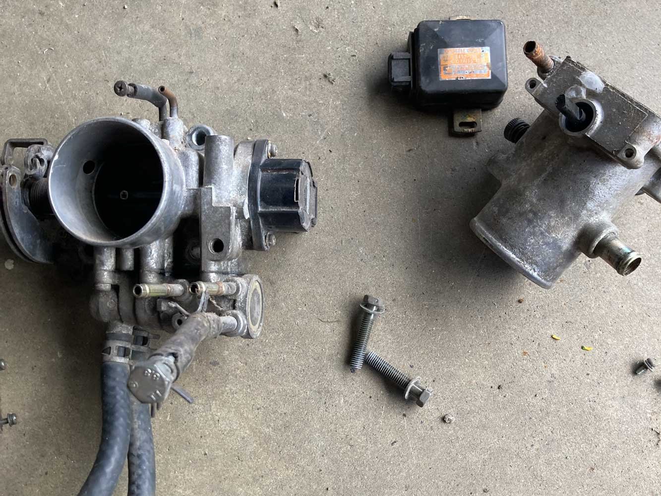
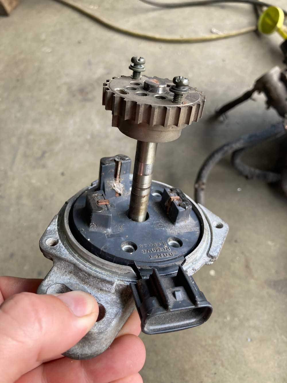
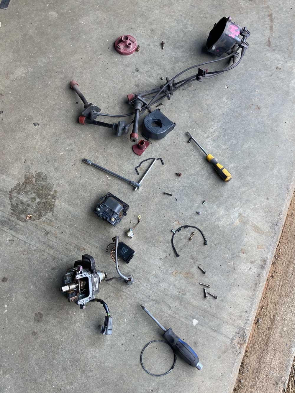
So because I have a big job to finish at the moment and am under immense time pressure, I got distracted and had a fiddle in the shed after staying up late last night doing research. This is my 2TG pile. First I had a fiddle with throttle bodies and TPSs. On the left is a TVIS Redtop 4age throttle body and on the right is the 2tg one. The 4age has a potentiometer TPS vs the switch type of the 2TG The 4age inlet manifold is on the left, and the 2TG one is on the right. The bolts are the same width apart, but the 2TG ones have a smaller spacing vertically. There is also a 10mm difference in size between the two TB holes. The nerd that can't weld alloy in me has been working out how to design a bolt-on adapter plate to bolt the 4age throttle to the 2TG inlet, but the logical option is probably to make a weld-on plate that the 4age throttle bolts to. We looked into switching the TPS over, but swapping the whole throttle seems to be less fiddly and results in a bigger throttle, and bigger is better right? The next little mission was trigger wheels. We searched through the shed for old Toyota distributors and found an AE101 5AFE one and a Blacktop 4AGE one. I pulled them both apart and decided the 4AGE one on the right was a simpler setup, but will take them both to Max and see what he thinks. I've read about how ideally you want to run your trigger on the crank due to distributor slop etc, but this seems a whole lot less ugly. Hopefully, we can drop these guts into the 2TG distributor and get a cam and crank signal off it. It will be easy right? (This is what people say when they come to me for website things that don't turn out to be easy). I've found this discussion https://speeduino.com/forum/viewtopic.php?t=495&start=100 that relates to a 3SGTE that seems to use the same style of trigger wheels.
1 point
-
1 point
-
I glooped the two halves together, bolted them up, bolted the tailhousing on and let it set. Following morning it was bolted onto the engine, unsurprisingly a bit heftier with all the gubbins placed back within the box. Its about 9kg heavier than the standard imp box. I then started to fit the first part of the gearshift linkage. The first of those snazzy universal joints, handily available in a diameter to suit the shifter shaft on the Subaru box. I just needed to add a small locating hole for the grub screw... Universal in place.. Engine and box were then bolted back into the car. This bit is so quick and easy when using the 'engine stand 2000'. It takes about 10 mins and I'm getting quicker. It'll be slower when there's shift linkage to undo and driveshafts to slip out of the way. But at least the main heavy awkward part is actually easy. That lot in place I took some pics. Its neat to be able to look out from the one of the lounge room windows down onto the workshop floor and see this... With that lot in place I was able to suss out the angles I could get away with, as shallow as possible and allowing for the handbrake mechanism. I had this old imp gearstick assembly that @dmulally kindly posted over to me. Some previous owner of the car he got it from liked painting things. Everything. Multiple times... I scraped all the layers off, took it apart and cleaned off the dirty old grease. Discovered it had been cobbled together from two old shifter bases. It was originally a very early Imp unit when the very first cars had an automatic choke, which often proved problematic. Hillman then changed the cars over to a manual choke with a nifty little lever in front of the shifter. This mount had been added to the early base. Which means they must have chopped up a later baseplate to get the choke mount. Why they didn't just fit the entire newer base plate I don't know. But what I had in front of me was a frankenstein of base plates with barry spec welding and fixes, but also including a not too badly made bronze bush on the lever where there is normally a (wornout) plastic bush. I had a couple of shift rods to choose from. I chose the least worn. Moving back to the gearbox end I machined up some shaft ends from stainless bar to suit the universal joints. I had some stainless tube and welded the ends in place on the first shaft that runs from the gearbox universal down to the tunnel. Now I needed a sturdy, slippery support to mount in place of the second universal joint. This will not only take back and forth movement on the shaft but also a bit of thrust loading created by the angle on the connecting shaft. I had already bought a lump of slippery hard engineering plastic with this application in mind when I had ordered the plastic for the flywheel thrust bearing a while back. It was bright yellow. Luckily not seen under the car as it would clash with the blue paint. I put a hole in it and machined the outside down. Which also created a pile of pretty swarf.. Then reamed it out to 1" Still a bit tight so out with the adjustable reamers.. until it was just right... Then made a stainless cradle .. The cradle got some wings welded in place and I dug the rivnut tool out.. Mount now bolted in place in the tunnel I had to chop the last tube to the right length, weld on the end and bolt the universal in place.. The front end below the shifter was was standard imp stuff and this is where problems popped up to throw a medium sized spanner in my workings. The side to side gearstick movement across the gate was minimal. Ridiculously so. Like about 1". Or 25mm in new money. Yet the fore and aft movement was about right. But quite stiff. I was contemplating why this was so and what I could do to remedy this when I also noted that 1st gear was where 3rd was and 3rd was where 1st was. Poos. Four years ago when I had compared the Subaru gearshift pattern at the box to the imp unit I thought they were exactly the same. But I had not accounted for the reverse rotation taking place under the imp gearstick. Also I never really thought much about how little of rotation the Subaru box needed on its shifter shaft to shift the internal selector across the 3 rods. Its a tiny amount, like 3 degrees say. Whereas the Imp box has a shorter internal selector and requires more rotation at the shaft. Hence the Imps gearstick knob only moves a teeny bit when coupled to the Subaru box. But the Subaru box has a standard/similar amount of rod movement within (ie 1-2 and 3-4th) which was going to make things trickier to fix. Simple linkage/leverage multiplications that is easier to see than explain. Sorry if your brain hurts. I had to hurt my brain a little bit to suss out a solution but there was only a little bit of smoke. The reason the scooby box is different becomes obvious when you see the scooby shifter setup. Which luckily I can show you because last week thanks to @Leone I was put onto a local fella to me who happens to have many old Leones and Brats kicking about his property and he had a spare leone front wheel drive box that I wanted (always handy just in case...) His property is amazing!!! Long 4wd only driveway up to a ridgetop house with stunning views out over Tasman Bay. Old leones just kicking about... Luckily we have our trusty old 4wd Hiace and that became the days gearbox transporter... Box on bench. Look at that shifter mechanism... The shifter rod attached to the gearstick only rotates a tiny amount when the stick is moved sideways across the gate. But the rod moves 10mm in each direction when shifting for and aft. Simple. Robust. Very Subaru. I can't copy it though because I have turned my box 180 degrees. No matter where I put my pivot point (below or above) I'll have one of the planes working backwards. So I decided to build a new shifter base setup. The most important thing was to reverse the rotation so the gearstick pattern is correct. The imp pivot point needed raising to allow the offset shaft end to be rotated to above rather than below the centre line, so reversing the across gate movement. I would add the ability to adjust both rotation and lineal movement. Started with a new pivot cup because I was not happy with the worn and Barried pressed steel item.. I dug out a large lump of steel bar... Chopped out a square and cleaned it up in the mill.. Big drill = big hole.. Rough machined out a cup shape. Cut a form in cardboard to suit the brass ball and used a die grinder bit to finish the shape... Grinding paste time... Slots for pivot pin.. Lightened the lump down.. Built the shaft up with weld and machined it down so I could add a lower pivot point. Milled some steel like so.. Welded a boss on.. New socket for shift lever ball end... Cut out Barrys previous workmanship... Machined up some spacers and a base plate.. Welded up a little tower (my stainless and steel tig welding is definitely improving, helped muchly by realising that not being able to see what I'm doing does not help much and finally admitting to my age and buying some reading glasses....) Welded tower to base.. Now all together please... Bolted together. You can spot the adjustable rotation, which the spacers allow for, along with adjustable pivot point. In place... Yay- it works! The shift pattern is correct and the action is much smoother. The spring loaded indents on the internal gearbox shift rods are quite stiff, which I noted was the same on the other box with its stock shifter. Its a bit baulky to push past the synchro baulk rings into gear but I think will feel better when the gears are actually rotating. There's certainly no slop in the system and it feels very mechanical - not rubbery. I now note how much flex there is around the shifter base in the imps tunnel (granted a very rusty shell..) Its something I might just try to stiffen up on my blue Imp when fitting this lot in. Phew. That was a little mini engineering mission I was not expecting but that's this project in general1 point


.thumb.jpg.570970b401ac8d26ce9af7c1bf2bd8cd.jpg)


This leaderboard is set to Auckland/GMT+12:00