
Leaderboard


Popular Content
Showing content with the highest reputation on 06/16/22 in Posts
-
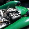
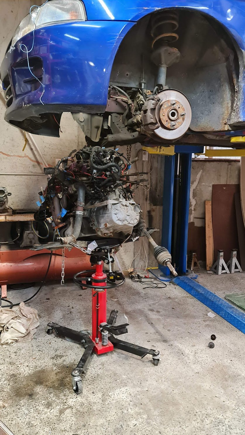
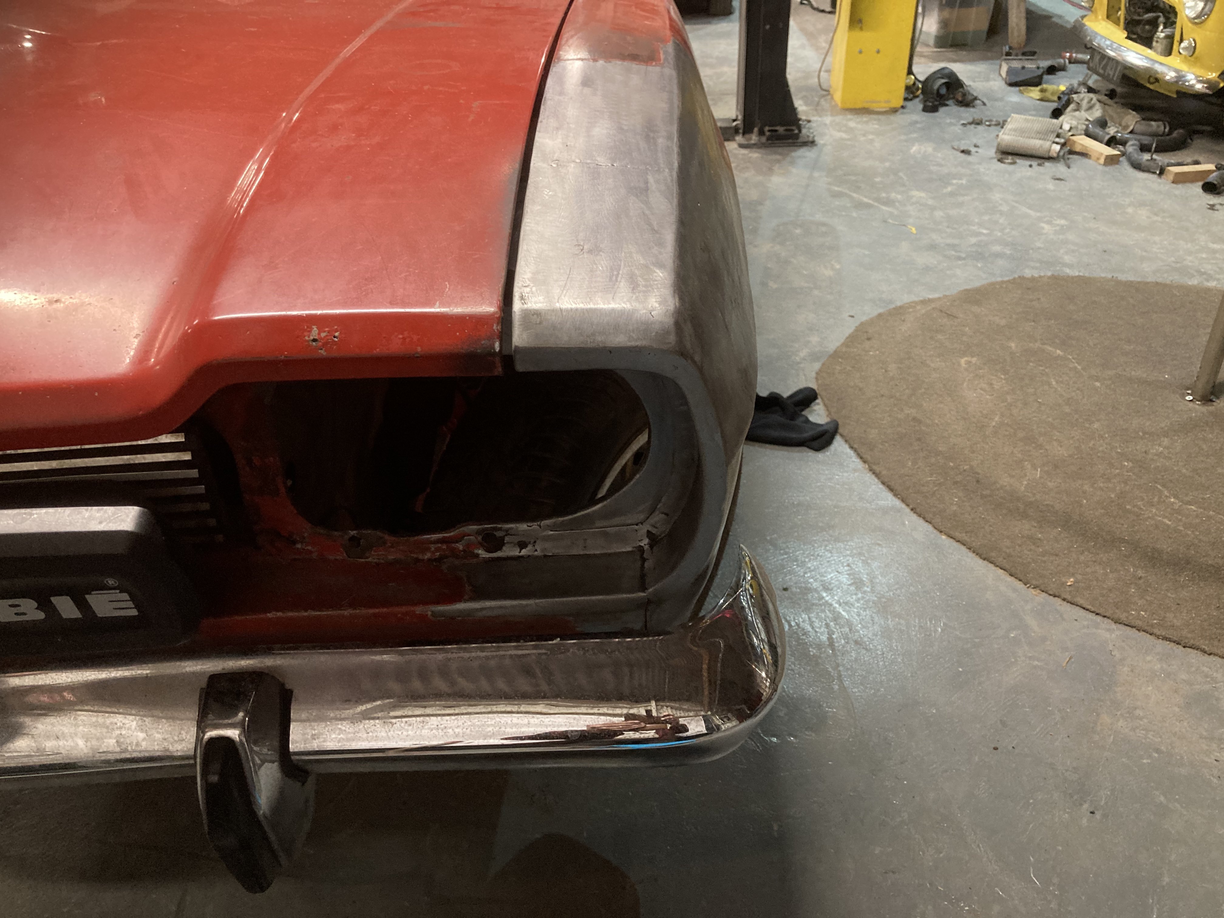
I got this back when i was an apprentice and did many of the period correct mods. RB30DET, cut a hole in the front bumper for larger intercooler, loud exhaust, terrible surge tank in boot, poorly fitted gauges (not in the A pillar to my credit) etc etc. It went terribly fast, and ran kind of poorly due to some lol issues that i never worked out at the time. I went overseas not long after and i kept it in an old barn on dads farm with dreams of someday spending a heap of cash on it and doing skids etc This pic was early 2019 when we dragged it out of the shed. Lack of genuine barn dust due to being well covered for 10 years. Nothing happened until maybe a month ago when i got the motor out and apart. Assume the position like the rest of my shed - bonnet up.. Im not sure about the condition of the crank, it has some marks and has already been ground undersize, so i stripped a spare rb30 and will get it measured up and the machining done in July hopefully. So far, i have nitto rods, CP pistons 8.5:1, link G4X fury, 1000cc injectors, GTX 3582r, sinco manifold Its 4wd so i might buy one of those flash PRP block brace/adapter plates. Apparently they are necessary, as if you have 600+hp and a front LSD you will crack the block. But they are expensive, and so is a front LSD. so i might pass on that. Also bought a bosch DBW throttle, and got a 350z pedal assembly, they bolt straight in so that was an easy win. I have some time off in July so hopefully ill make some progress23 points
-
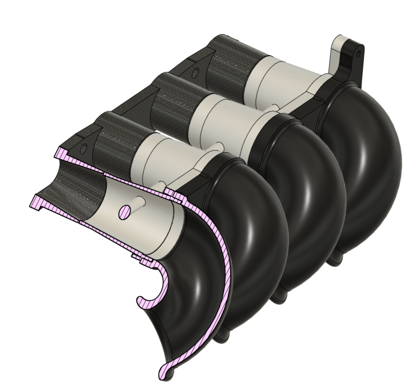
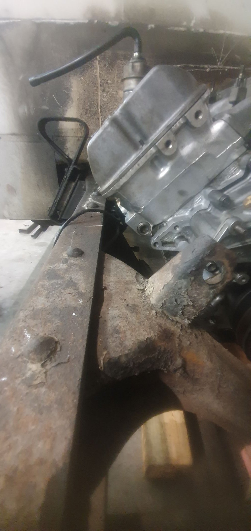
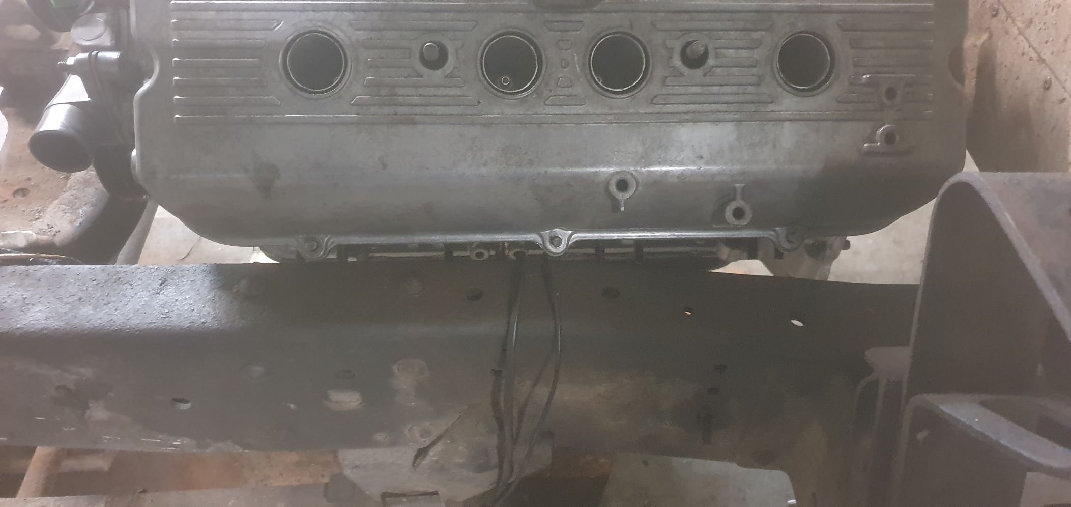
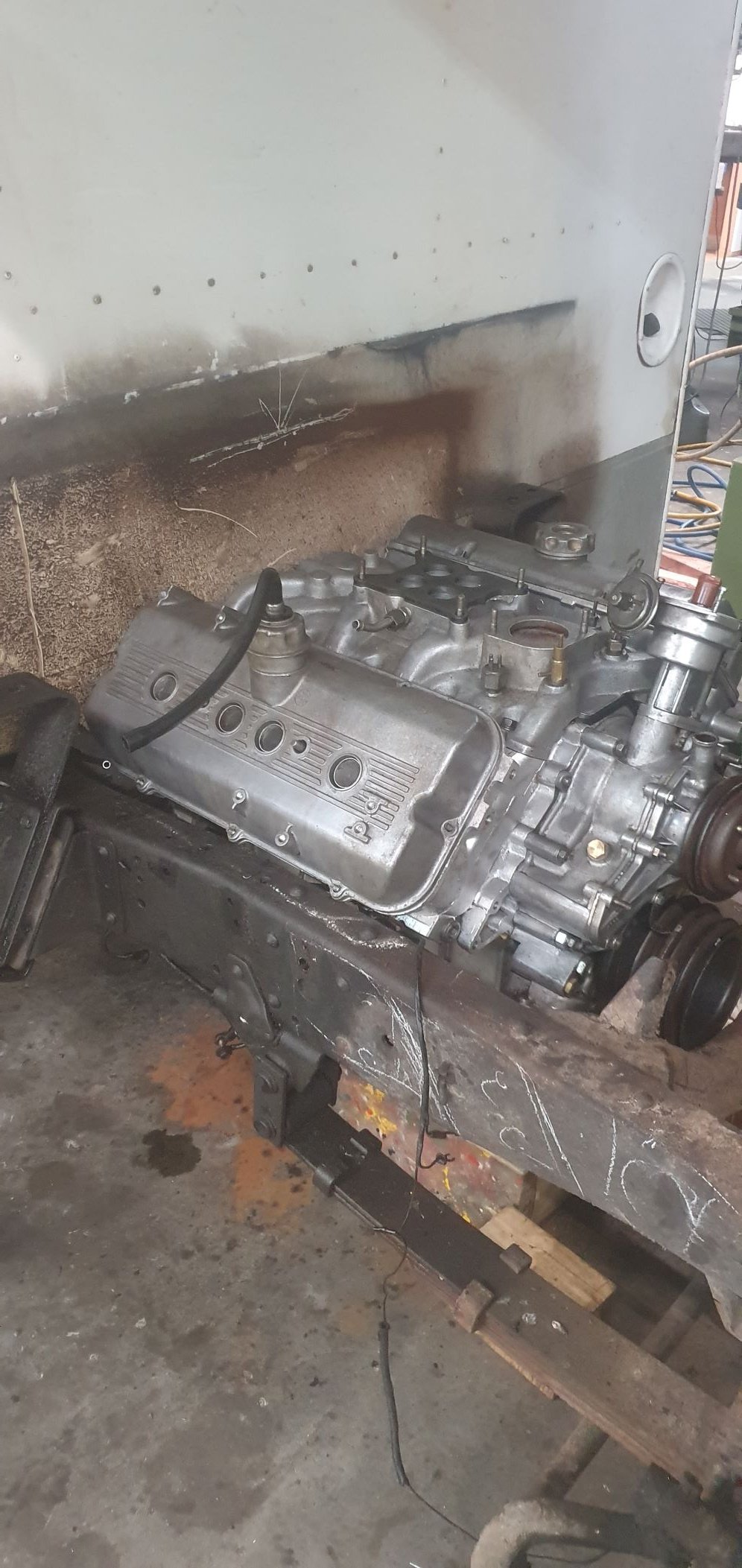
So while I plan out what my induction and exhaust setup with consist of I thought it best to get the alternator sorted. The goldwing engine originally had its alternator mounted off the back of the engine on a seperate casing now removed and driven via one of the many gears that resided within this casing between the engine and the clutch area. That area is now taken up by the bellhousing I have built and the alternator has to go on the front of the engine (which now the back ? of the engine as it sits in the imp..) and be driven off a crankshaft pulley that does not exist. This is what it looks like .. That little round cover hides the main cambelt drive pulleys and has a belt guide plate marked with various timing marks for setting up the ignition.. Under that pressed steel disc resides the first of the pulleys. Sandwiched between the pulleys is a 12 tooth trigger wheel - handy for my planned engine management on a six. I'll replace it with a 36-1 wheel though. So I need to machine up a few bits to allow the crank to run a mini v belt pulley and drive the Honda alternator which I had picked up at the local wreckers will sit about here... At another wreckers I found a pressed steel 5pk pulley from a power steering pump that was about the right diameter, had a flat mounting face and bolted in place with 4 little bolts. Ideal for my plan. I cut it down to suit a 3pk belt.. Then I popped a big lump of steel bar I luckily had left over from some other job into the lathe and machined up a hub with a locating extension on one side to match the inside of the cambelt pulley, of which which extends beyond the crankshaft nose by about 3mm. It drives , via a pin pushed into hub, off the hole in the cambelt pulley, which is there to locate the original timing plate.. The other side of this hub I bored out as far as I could whilst still allowing enough meat to bolt the pulley on. This hub then bolts onto the crankshaft, eccentrically located by the camshaft pulley and held fast by the crankbolt.. Then I machined an alloy 'plug' that fits snug into the bored out hub, machined on the end to centrally locate the steel pulley, rather then rely on the bolts.. And all lined up... So now I have a front drive pulley. Yay. Next up is making some sort of way to mount the alternator securely and not too ugly considering its going to be right there, centrally on view. Starting the mount by making lots of little tiny bits of alloy to tread about the workshop with this tool... I cut some strong alloy plate and mounted it to the top of the engine using several of the conveniently placed cast in mounting points scattered about the place on top of the engine. Thanks Honda I had to add a support on the front, easily bolted to the cambelt housing. Now I had a place that the alternator brackets could be bolted to. I just made it up as I went along and machined bits and pieces until I had what I was looking for. I wanted it to look a mix of between sort of factory and sort of 'race car'. I had lots of fun making more alloy swarf.. Of course I cut my plate too narrow... Eventually I ended up with all these bits to piece together... Together they made this.. But before I plonked the alternator in place I had to clean it. It looked horrid and had obviously resided in a Honda of some ilk with some serious oil leaks. It was also a bit corroded and things didn't want to pull apart too easily. I made a bespoke little bearing puller.. The filthy alloy castings came up nice with a petrol bath.. and even nicer with some wire brushing... While it was apart I cleaned up the slip rings... Painted the centre black. It will possibly be repainted in Imp blue at a later date, as a treat if the engine swap works out ok. Its just a look I quite like - call me 90s boy. Bolted it all back together, complete with a new main bearing that I happened to have in stock (must be one of the most common bearings ever -35/15/10) Then excitedly bolted it in place. My Honda goldwing now has a standard alternator mounted in a pretty normal fashion and it looks nice and neat... With that sorted I can move onto making the cooling pipes and induction setup. I have still not fully made my mind up on what route I'll be taking here but I'll probably to bite the bullet and click buy now on a set of itbs so at least I have something to play with and go from there. I need to find a set of suitable top feed injectors. Something around 200cc at a guess. The standard Honda goldwing 1800 items look like they'd be ok and pretty compact. I'll be making the mounting seats to suit, which I'll then weld in place on the stock intake runners. Fuel rail made to suit.18 points
-
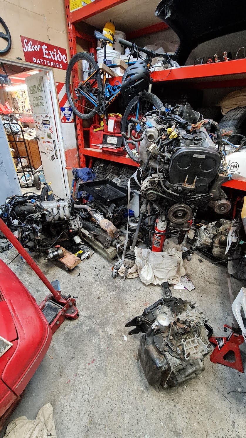
long time no hear. Have had the work/life balance tipped way too far to the work side since jan 21 and haven't done much on the car. I did get the engine assembled, and @Bistro gave me a hand to install and test drive/run it in sometime maybe earlier this year. Engine went really well. Knocked a bit with the old gas in the tank, but is going sweet with some fresh stuff. Just running a stock cam and single carb at the moment. I have a cam and a MAXX ecu to run the injected carbs. Need to do the fuel supply inside the carb hats, and order some lash caps to suit the cam. Hopefully ill get onto it later in the year. Image hosting seems to have packed a shit so ill try something else. As it sits, a good storage area for my other projects...12 points
-
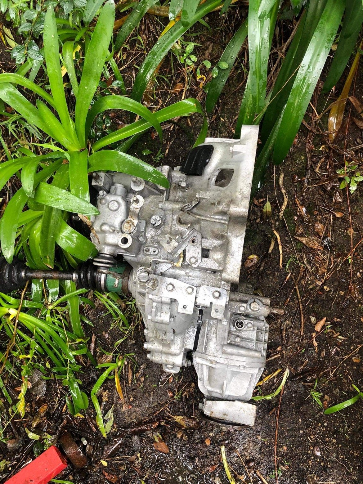
Thread sidetrack #1: The title for my our house/section might be available in roughly a month and a half. We've just had our finances preapproved again for another 3 months, as it expired. Been worried about getting our finances bounced due to changing interest rates etc. Hence needing to not spend any money etc etc. So that's a relief. Phew. So this is good and bad news for the Echo, it means hopefully the bulk of my housing worries are over sooner than later. But it also leaves me not much time to sort house stuff and do something with the car in the meantime. Once I've moved to the new place I'll not have a shed or anything for a while. So I really need to do something with it in the meantime to either get it mobile or make peace with it being dormant for a fair while yet. I'm thinking if I try fit stronger rods it'll end up having complications / cost / time blow out. If I buy an earlier motor with mechanical waterpump then I dont have 100% surety that it'll all swap easily and there are no complications with the alternator fitment and waterpump belt. So maybe for now I just get another Aqua one for a quick swap. Then when I've got some more cash monies I'll buy an earlier motor and put the good rods in it. Then hopefully get to a few events this coming summer as is, maybe with a little bit lower rev limit. Thread sidetrack #2: Also, a friend put his K24 swapped car up for sale. With aftermarket intake/exhaust, but standard cams. On the dyno this made 225hp at the wheels from 2.4 litres. So thats 93.75hp per litre at the wheels. The echo in its pre-blown up state on 20v throttle and standard exhaust made 141hp at the wheels from 1500cc... Which is 94hp per litre at the wheels. It's official, Prius motor is the new K swap Thread sidetrack #3: One of the reasons I've not worked on the Carina for ages, apart from being distracted with this. Is I really want to put a lighter engine in it. Turbo 1NZ seems like a really good option that will be really light weight, and tick all the boxes. I'd like to run an Altezza 6 speed box behind it, if so. So, I swapped one of my 3S bellhousings for a 1G version. So I've got both to see how they compare in case one's better. I've been meaning to take a bellhousing up to my Dads and sit it on the milling machine with the digital readout, so I can just work out the x and y coordinates of all of the holes. Then I thought... Oh wait I can do that with the printer. So I've got a rough-ish idea of where all of the holes are, and did the same for a 1NZ gearbox casing. The 1NZ bolt pattern is a little bit smaller on outside diameter than the 6 speed stuff. Not sure if that's going to work out good or bad for making an adapter. I'd also need to work out things like how deep the flywheel needs to sit inside it. Might need to shave off quite a bit of the bellhousing and weld something else on. Or something. Dunno yet, its a complex job and I'm feeling out of my depth. But will do some more research on it. The altezza's flywheel face sits quite far from the block, because they run a dual mass flywheel which is very thick. So it might be that the final overall length including new adapter needs to be considerably shorter. Which is also fine, as it pulls the gearbox slightly forward, and the stick is usually a little to rearwards on swaps. Anyone done something like this before? Any tips?
 10 points
 -
Also got some evo brembo calipers and 320mm ish rotors. There are a few types of adapter brackets so i need to find a decent set that will pass cert, or buy some 350mm evoX rotors and adapters for the front and 350mm 370z rotors for the rear. My overnight parts from the UAE turned up yesterday with the r34 gtr master cylinder to suit the larger calipers. They look like the will have some stopping power. The current brakes used to run out just before i got to the top of mt messenger.10 points
-
Chassis update: I managed to make it back to NZ for a bit, a couple of months ago, to have a go at this chassis building thing my Dads been raving about! Turns out it is actually hard work! Hes just finished both rails! I just got a bunch of machined parts done. Spring mounts and braces that go between the rails. Just have two sheetmetal braces to figure out then all of it can be bolted/riveted together (with a few more holes and some tweaking I'm sure!)10 points
-
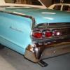
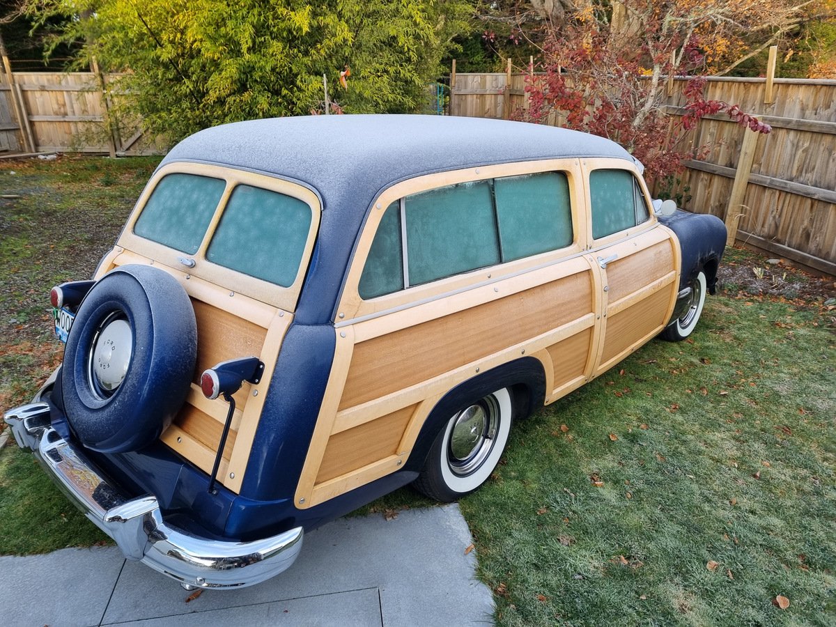
Took the working one away to Ohakune. Went well even after the frost so took a spin up to Whakapapa. Annoyingly left the petrol cap at National Park g.a.s and it wasn't there when I went back 90 minutes later so who knows what happened to it. Managed to find a substitute at Horopito Motors after sneaking entry on a Sunday when they were sort-of closed.
9 points
-
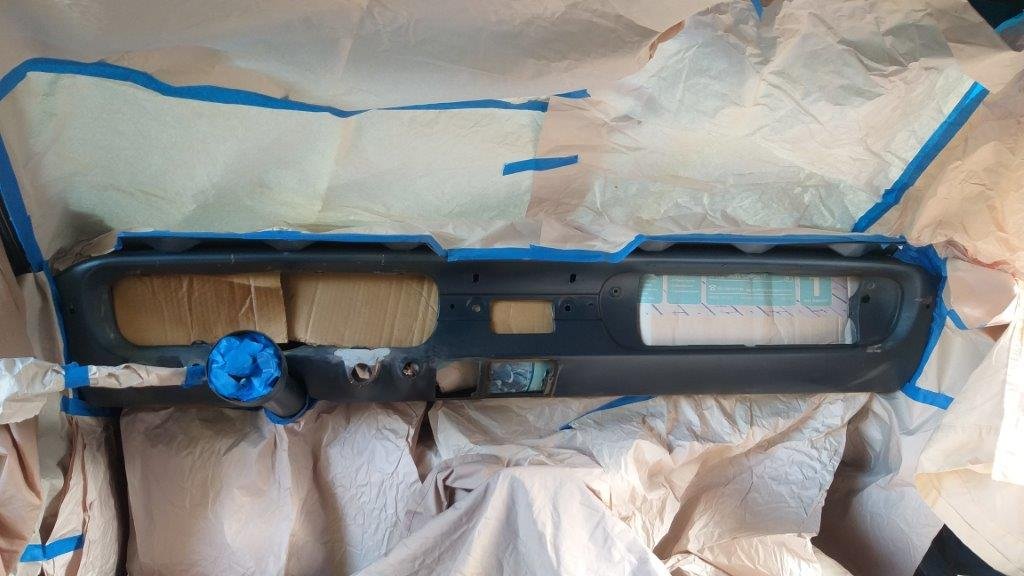
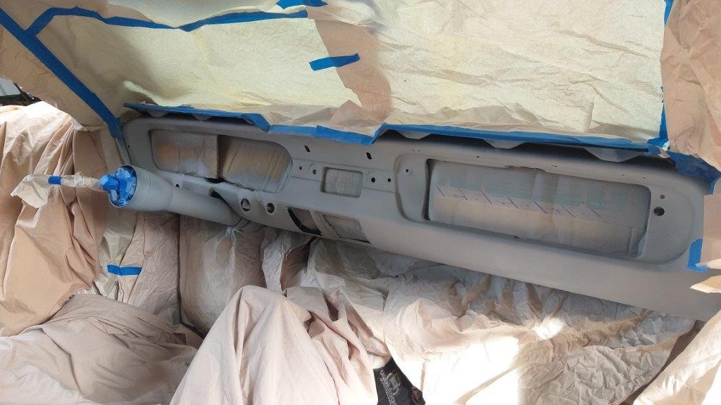
Work on the metal dash panel continues. Earlier in the week I massaged the metal around the ignition switch back into shape. It was a real bugger as there is a welded in dash support right in the way, so no chance of getting a dolly in behind. Did the best I could and then applied a light smear of bog to smooth out the remaining ripples. With everything else taped up I've chucked a bit of high build primer on it. There is one small low spot that I've re-bogged, so thought I would post an update while I'm waiting for that to go off. Thanks for looking.
6 points
-
Yes there is a definite lack of them around now. Its all thanks to the sideways hat brigade and their hectic driving style. Gearbox might be OK. Its a late 33 box i converted to push clutch. One of the main reasons for converting to e-throttle is to be able to limit the torque in 3rd gear, and 2nd if required. I have a complete transfer case and bearing set to give it a birthday and set up the clutches properly, plus a couple of big boxes to raid for parts should i need it. I have been converting 2wd navara box internals to fit RB for a long time now for a bunch of local drifters and have plenty of parts to keep my box going. However, there are a bunch of crazy norweigans who do a conversion kit for the bmw DCT trans. I think it will be about 10k which is a bit much, but dreams are free. Look up HPR tuning, there's some videos of a few 2jz and rb conversions. it looks awesome6 points
-
Mivec engine out of the parts car: Apparently I am into Lancers now...
4 points
-
He's now a Certified Forklift Enthusiast.4 points
-
3/4 ain't bad. Mains and rods torqued to spec and it spins freely which is good More spaghetti Turned it into this. Vtec wire re run and run the reverse light wires That's all I can do on the loom until I get the motor/box into the car. Those rings are holding up the process a fair bit4 points
-
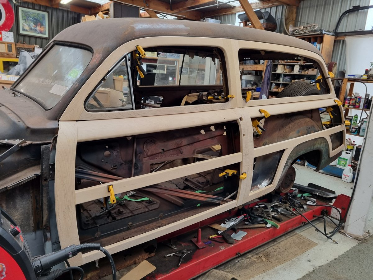
Another month already? Hot Rod club came for a visit so pulled some wood out to make it look like I've been making progress After getting some more steel I made a start on the bottom of the B-pillar
4 points
-
hi everybody. just to let you know where I'm at... I've looked at the motors I have here.. and I have a plan so cunning...you could put a tail on it and call it a weasel . just waiting on part4 points
-
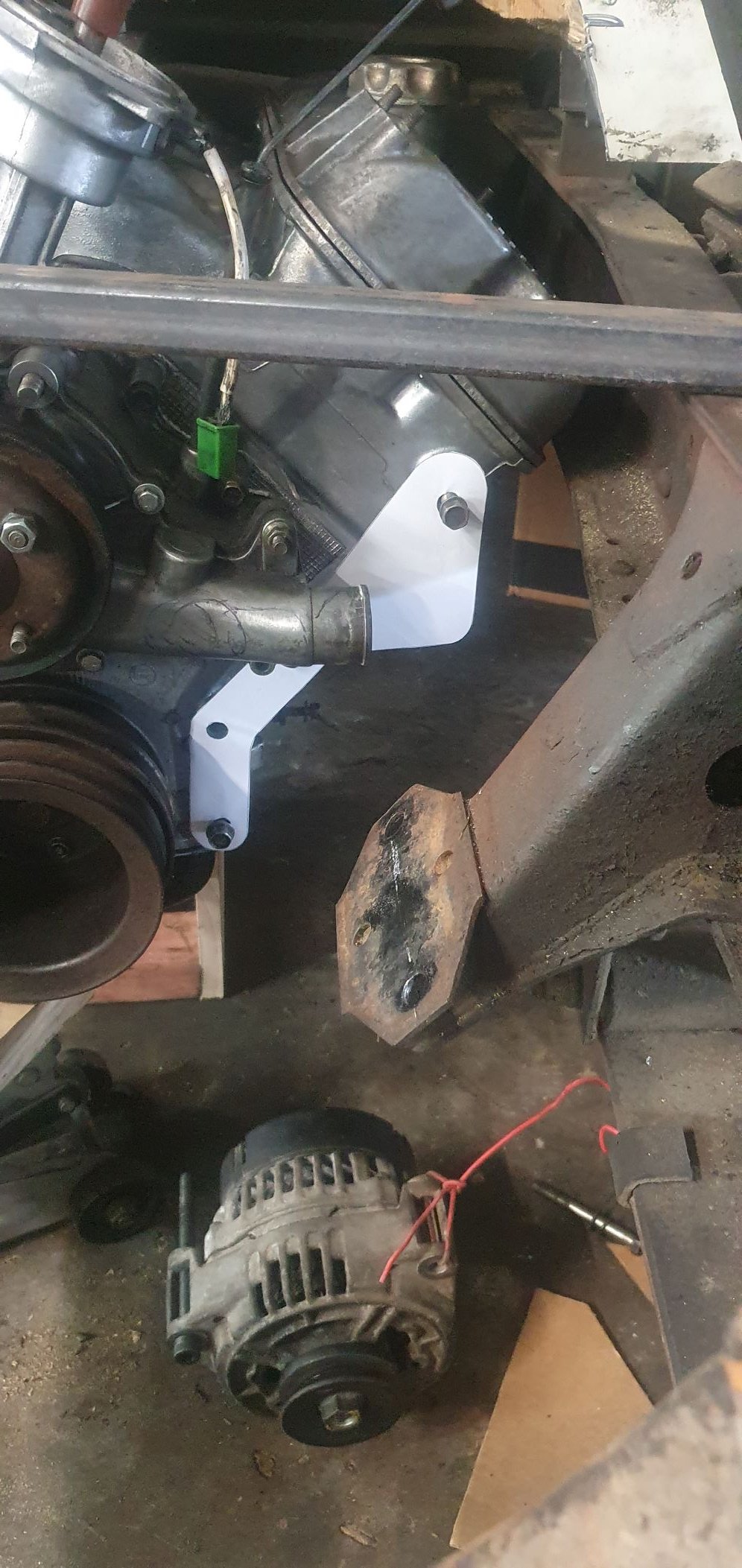
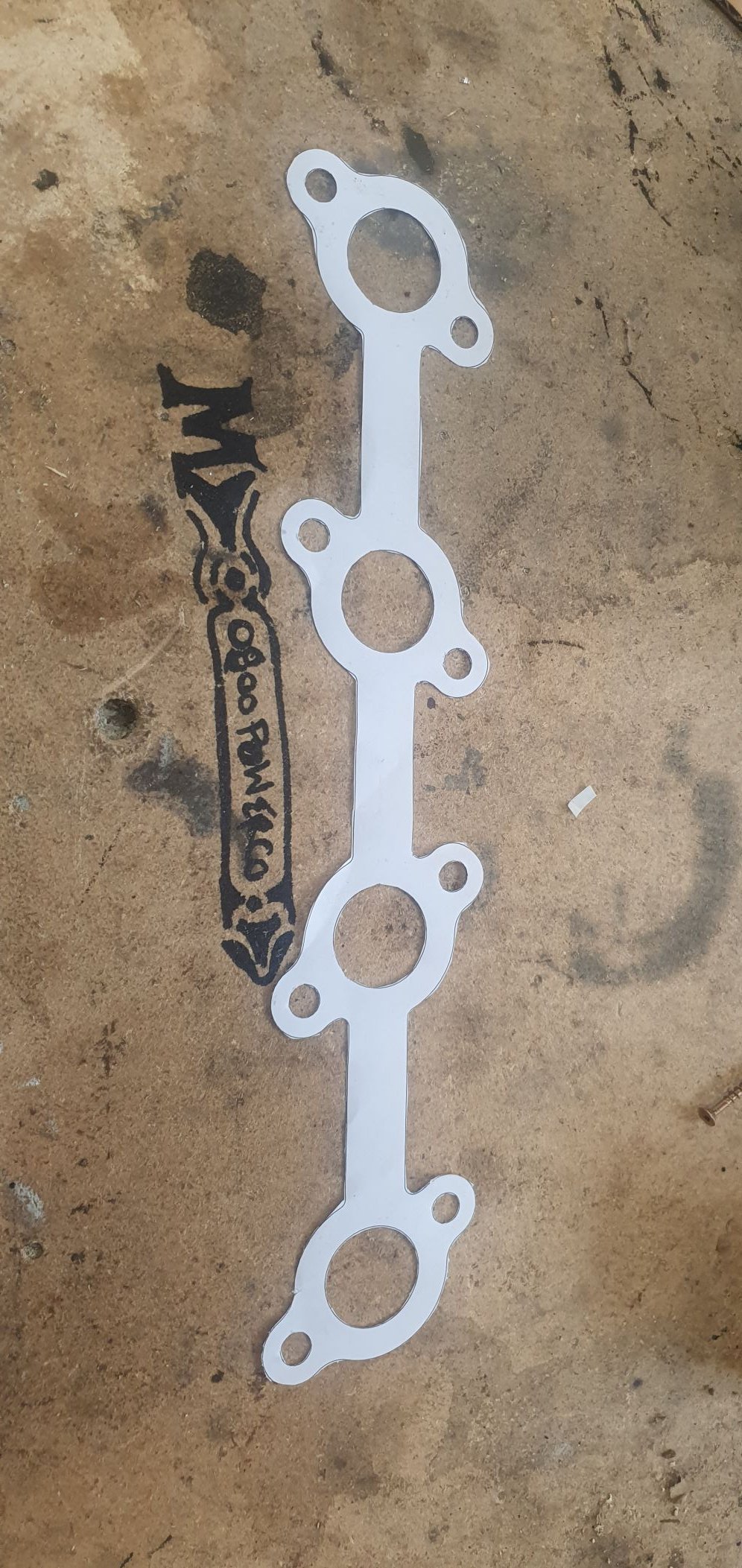
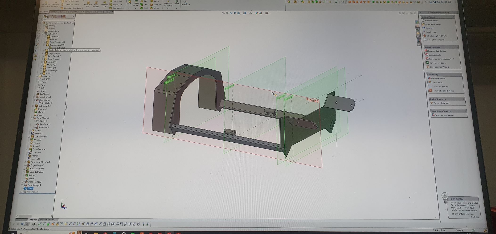
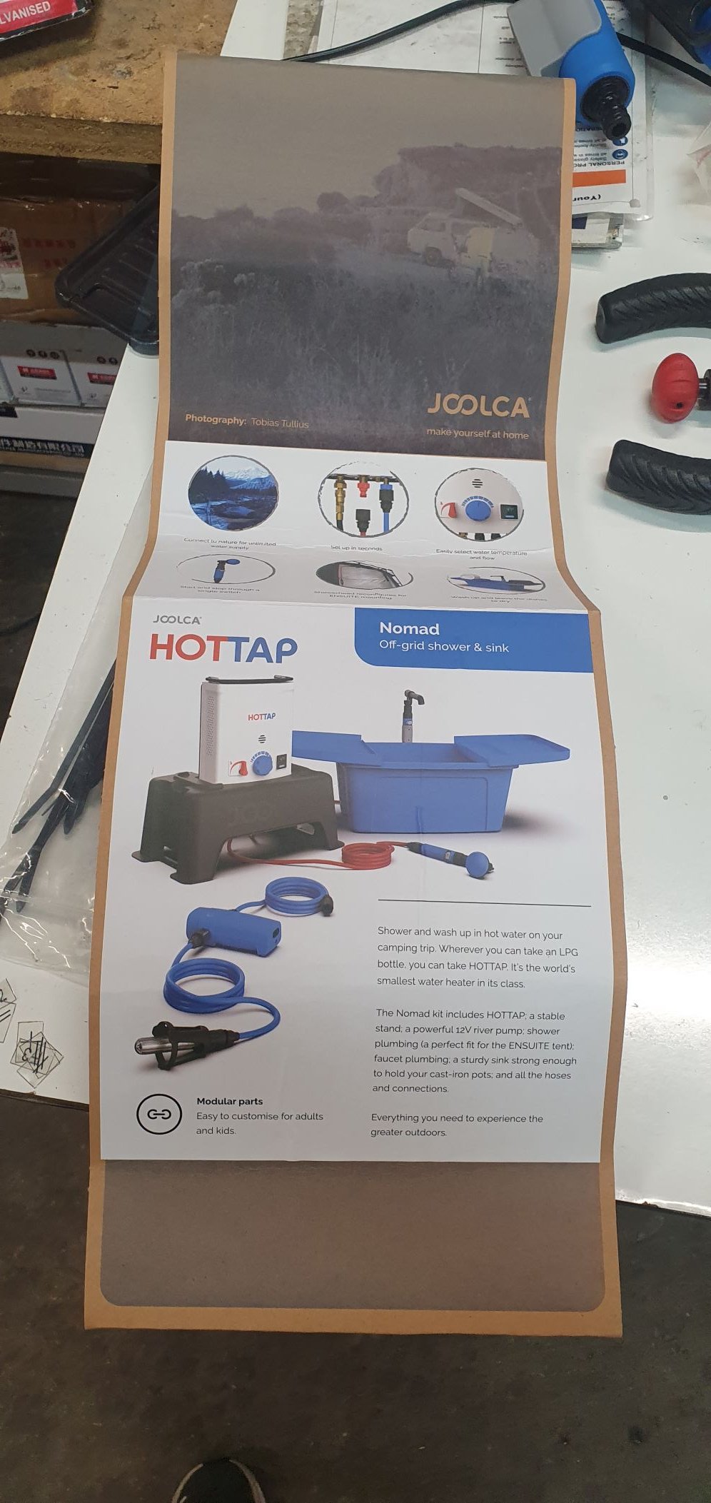
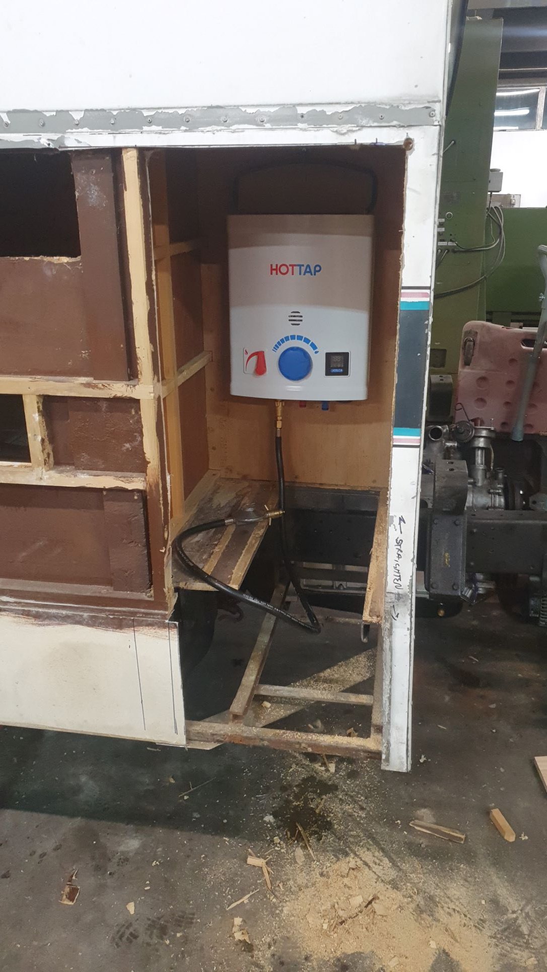
Been a while since I posted anything, progress has been not too bad. The engine has been hanging out in there for a bit now, Im pretty comfortable with it. I decided to start working on the mounting and some of the other ancillary bits, as well as sorting out the gas locker and battery area. Got a sweet new toy too! So I threw the engine mounts and trans on and really got the engine into the final resting posi, or thereabouts. Started sussing out what to do re engine mounts, which necessitated starting to sus out what to do with alternator.. I have a 140A alternator form an old benz I scrapped so kindof dummied that into place, took original pully off old motor and bored centre out on my lathe for dummying purposes (still unsure if crank to alt pulley ratio is bang on - minor detail at this point). Anyway a bit of faffing about and we settled on a way of mounting and tensioning that ensured the belt doesnt foul the water pump housing (its pretty close). Made a cardboard template for the bracket, then drew it up in CAD, then printed 1:1 and cut out and checked fit. Was good. Did the same for header flanges. Also good. Next mish was then to CAD up the engine mounts, or rather engine cradle... So I spun up dome hollow bosses on the lathe for mounting to the original mounts, then roughly figured the width across these. Did a butload of measuring and crawling around underneath, fucked off a whole bunch of shitty wiring under there while I was at it. Then drew up the engine cradle, which mounts between the original engine mounts and gearbox mounts. Ill make a gbox xmember later. Looks like tail shaft will be about 600 long. I CAD this up with the intention of mounting the engine without the alternator to get engin placement right, and for ease of fab, then Ill clearance the mount later to accomodate the alternator. I need to release all these files for cutting now, but just been sidetracked with other bits.. So I started sorting out the gas locker, random I know but I kindof want to get the fuel tank situation sussed (possibly going to find another slightly bigger one, different shape), anyway that kindof relates to the gas/battery locker as there is some encroachment there.. So I removed a shitload of shit out of there, cut and trimmed everything that needed to go so I have a nice simple rectangular opening I can start to work with that also maximises use of the space. There will be a fair bit going on in here. Starter and house battery, battery splitter rig and solar controller, inverter and gas califont for sink and shower (see below, I got me a Joolca!) For the battery splitter/solar controller I have done a bit of digging around, there appears many different ways you can do this, but I was really hoping there was a product that just did it all and sorted it for you...turns out I think Ive found it - https://www.kickassproducts.com.au/buy/kickass-25a-dc-charger-with-anderson/KADCDC25A-AND be interested to hear peoples thoughts on this, and also opinions on simple ways of doing this. For me this ticks a lot of boxes. Controls Solar, does battery isolation between house and starter battery, accepts alternator input. Only problem I see is I have got me a pretty big panel to throw up top, around 375w from memory. I recall it outputing around 40V peak in summer and this thing is only rated to 23V... anyway, good to hear peoples thoughts on this. Plan is to mount Joolca in the back, gas bottle in front and a floor between gas and battery cavity. So I trimmed out the gas locker nicely, framed it up and instated a new rear wall for the locker from ply, reused some old bits of framing I chopped out. I gave the Joolca a good thrashing tonight. It pissed me off a bit, but I think it was because I was reciring water and it doesnt like the inlet temp of the water too high otherwise it cuts off the flame. I brought the Nomad kit for $650 thinking the shower head and tap looked the goods. They are, but I have since thought maybe I just hard plumb everything and only use the flash Joolca pump...will see. So the plan is to fully line the gas/califont locker with ally sheet and then duct from the door and have an exhaust fan sucking the hot air away through a hole behind the cab., go a nice louvred panel for this today and can reuse a few other bits of steel flashing I pulled from elsewhere. I also got some extrusion angle today for framing up around the gas locker opening. Next mish is to get some 0.9mm ally sheet for the outside cladding and gas locker. I will prob just draw all this up and then order a bunch of laser cutting, as I dont have a guillotine. I am fortunate enough to have a brake press though, so will draw to spec and then fold everything. Id kinda like to get the gas locker somewhat completed before refocusing on the engine. I probably wont do that though and jump all over the show or start a new mission...I cant really fully sort the gas locker until I commit to batteries, inverter and the like. That shit is proper money which I dont have right now. so will need to wait a bit and plan as best I can for what will go in there. Ive also started contemplating a bit of body work. I have decided to mount the shitter in the cab under the middle seat as there is enough room for the cassette in front of the engine, and also, its pretty funny. Anyway, thats my lot for now..
3 points
-
the rod wanted to be 0UTZ not 1NZ3 points
-
Shit man I'm happy to put in a fiddy for another junker engine to see things keep moving, I am sure there are many more here would do the same. Time for an onlyfans.3 points
-
Yeah its pretty basic math that a 3" pipe is needed here.3 points
-
Have killed a motor or two, I can relate to your present situation. In my case, the car was sent to the naughty corner until I could muster the $$$/fucks to start again. In your case, option B is take donations from willing people. Even if just to score another stock bottom end to see your car back on the road in only 1 weekend. (Assuming it's not raining) this thread is more entertaining than sky TV. I'd chip in $30 happily. It really feels like we all share in your success. And every blown engine is a learning experience/scars have the power to remind us that the past was real........2 points
-
Shit yeah Theres a cast turbo manifold on fb for 150.......2 points
-
I think 8.5 will be a good comp ratio. I only want to run petrol. The calipers are all Evo 6-9 brembo. I can get adapters to run the 370z rear disc and the internal handbrake will still work. Plus with the r34 master it will give me a correct front:rear bias without any tomfoolery with a bias valve and whatnot2 points
-
I stepped in some rocking horse shit , slipped and landed on a unicorn. yup that’s right, I found a stock GTX gearbox that has been rebuilt. it us now on its way to me along with a left driveshaft and another baby unicorn, a working AFM. price paid, much less than I was expecting to have to pay for one. i technically have the parts to put together a complete car from a rolling body. Don’t dare me please, I can’t deal with that kind of pressure.
2 points
-
This was the house we were trying to buy, https://www.trademe.co.nz/a/property/residential/lifestyle-property/auckland/papakura/ardmore/listing/36017409422 points
-
Million dollar idea. oilyfans2 points
-
2 points
-
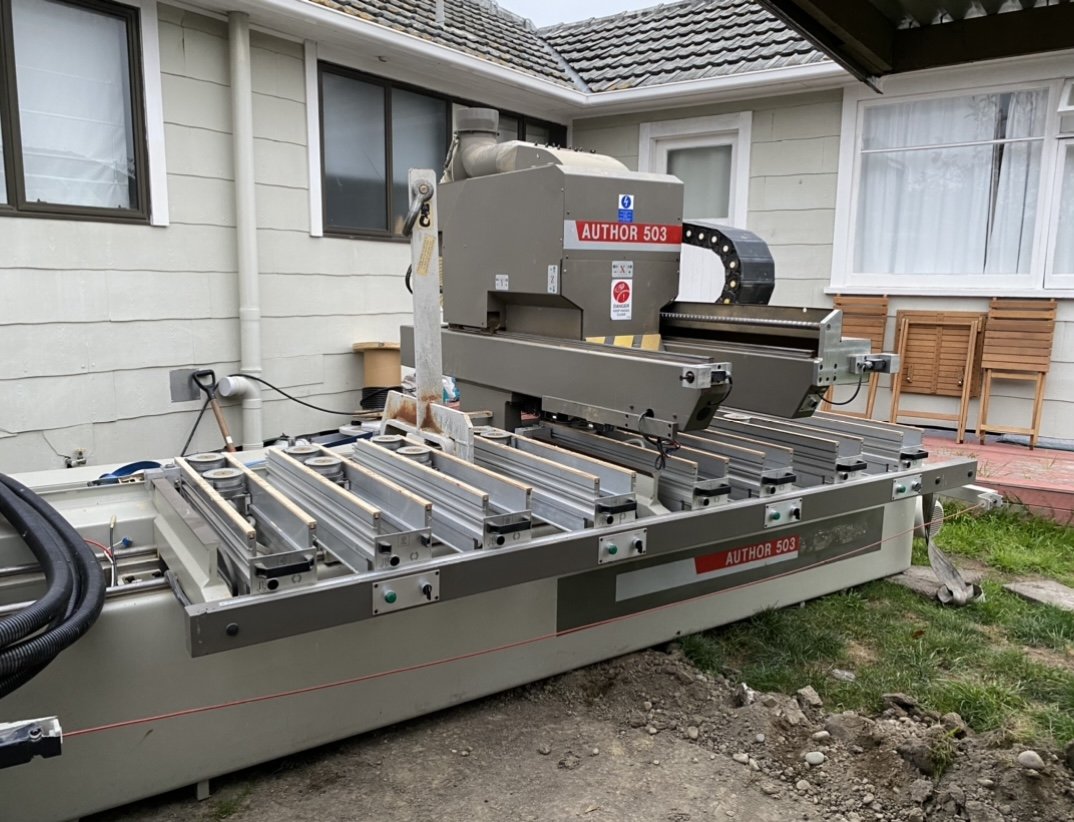
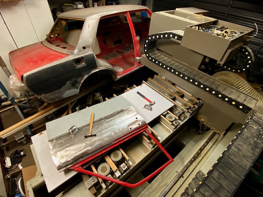
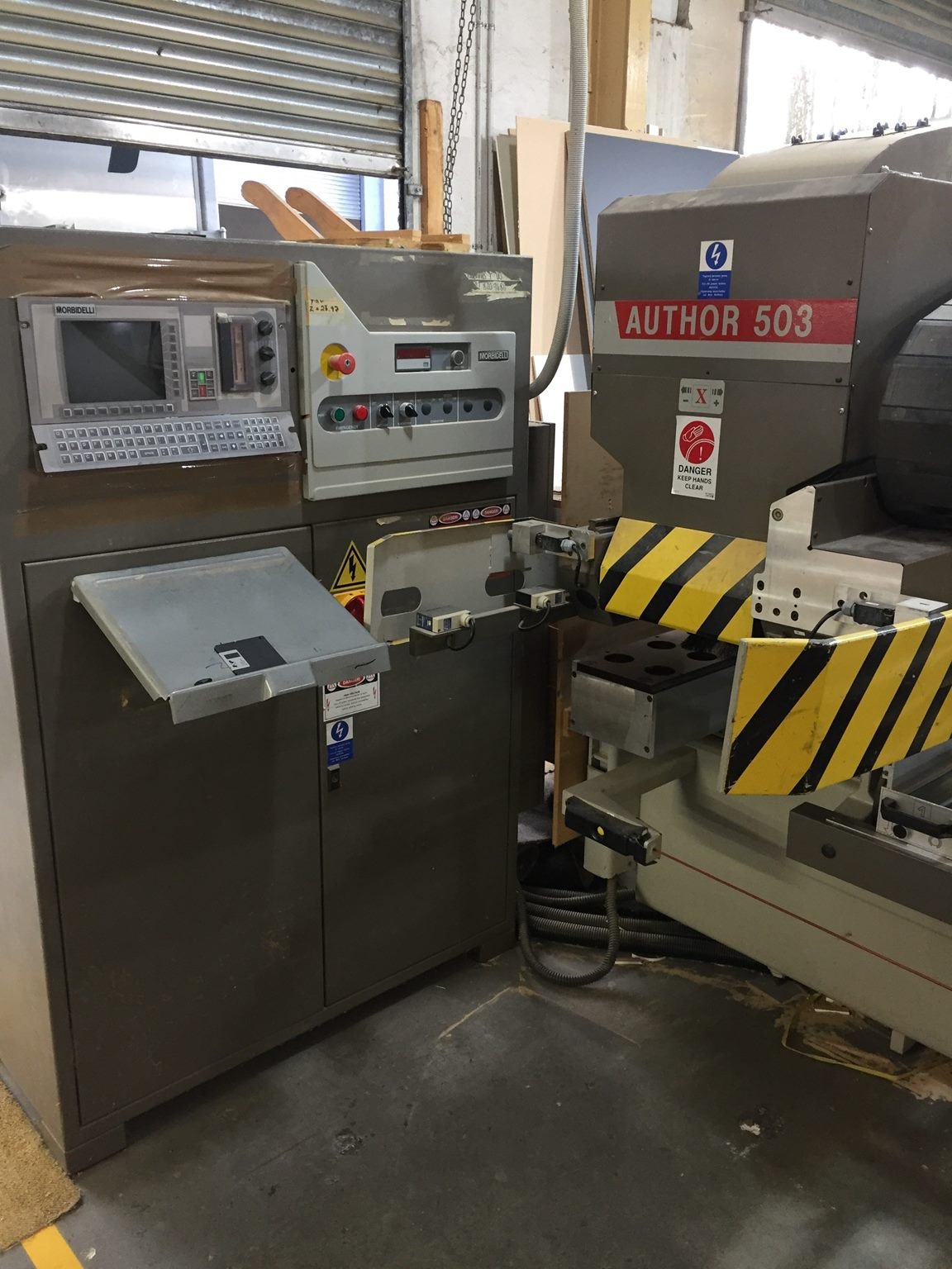
Well, this was never part of the plan. Mate gave me a message one morning linking a TM auction "This will fit in your shed right" Well yeah...... Cool, I hit buy now. Umm, what? I was now obligated to arrange the pick up of a 3.5t Morbidelli cnc router, condition unknown. Much to my surprise, after arranging an inspection, the staff fired it up and gave me a quick demo, the nightmare of owning more scrap metal was diluted with hope, this may not be a terrible idea. Key issues at this point 1) Power, I live in the central city on 1ph power, I need to get 3ph 2)Transport, my truck has a 3.5t tow rating, that doesn't include the trailer right? 3) Shed space, currently the shed has a divider which was half knocked down to fit the Datsun 4) Sneak past her indoors..... First off, Power The same mate that dumped this on me also offered the loan of a 3ph rotary converter, this coupled with a tame sparky resulted in a trip to the wholesalers, cables, switchboards and various tidbits were stacked up and brought home, I dug a hole and laid a hefty cable. Issue 2 Transport Realising that shifting such a machine from the other side of the city was well outside Bunning's trailer abilities I gave up any thought of 'doin it cheap' and dialled for a HIAB, best move, the truck even managed to trim a few trees I had neglected... Issue 3 Shedspace With a router now sitting outside, multiple trips to the dump were made and the remains of the partition removed, shifting the router in was and interesting task, I had envisaged using dynabolts, 4wd winch and pulleys to get it in, thankfully the loadskates were efficient enough that a ratchet strap was plenty to move it in a more controlled fashion. I now have a very large hunk of steel sitting in the way, at least it makes a good table! Now all this did not take 'a few days' the router sat outside the workshop for at least a week as I toiled away, any hope of sliding it by without the girlfriend noticing was well lost, I may still be in debt a cake or 7. Just needing power hooked up and sign off by the sparky everything was go, until it wasn't. -Sparky had legit delays -Reality of the machine sprung a good deal of remorse. You see, the manufacturer Morbidelli are the type that decide to swim upstream and do thing just different enough that its recognisable but still not quite friendly, while this machine will do cabinet production well, it can't be tricked into making car bits, nor will it accept anything programmed by not their software. Once the sparky had called by and we fired it up, multiple air leaks meant nothing could be run as my small compressor couldn't get the pressure up. Crap. A shining light of the deal is a full folder of schematics, spending far too many weekends reading, I narrowed down the electrical faults, cleared one by one and isolated unrequired solenoid banks, after further poking through manuals it became very clear, this machine was here to make shelves, all else can go to hell. With various tricks and rewiring of circuits, we managed to function test the 3 different spindle drives, all three axes and the vacuum pump, with proof the mechanics are fine, round two can begin. I have ordered the hardware to hand over the controls to Linuxcnc, along with prioritising of the pneumatic controls, this should simplify the machine to something which is far more flexible than the standard function it has run. I also have some plans for the table and work fixtures, this machine is so heavy and rigid, I see no reason it can't mill aluminium and plastics which along with timbers, will be a pretty handy toy to have (well better be for the space it takes up) Stay tuned, as the parts arrive i'll document the conversion from Italian to LinuxCNC
1 point
-
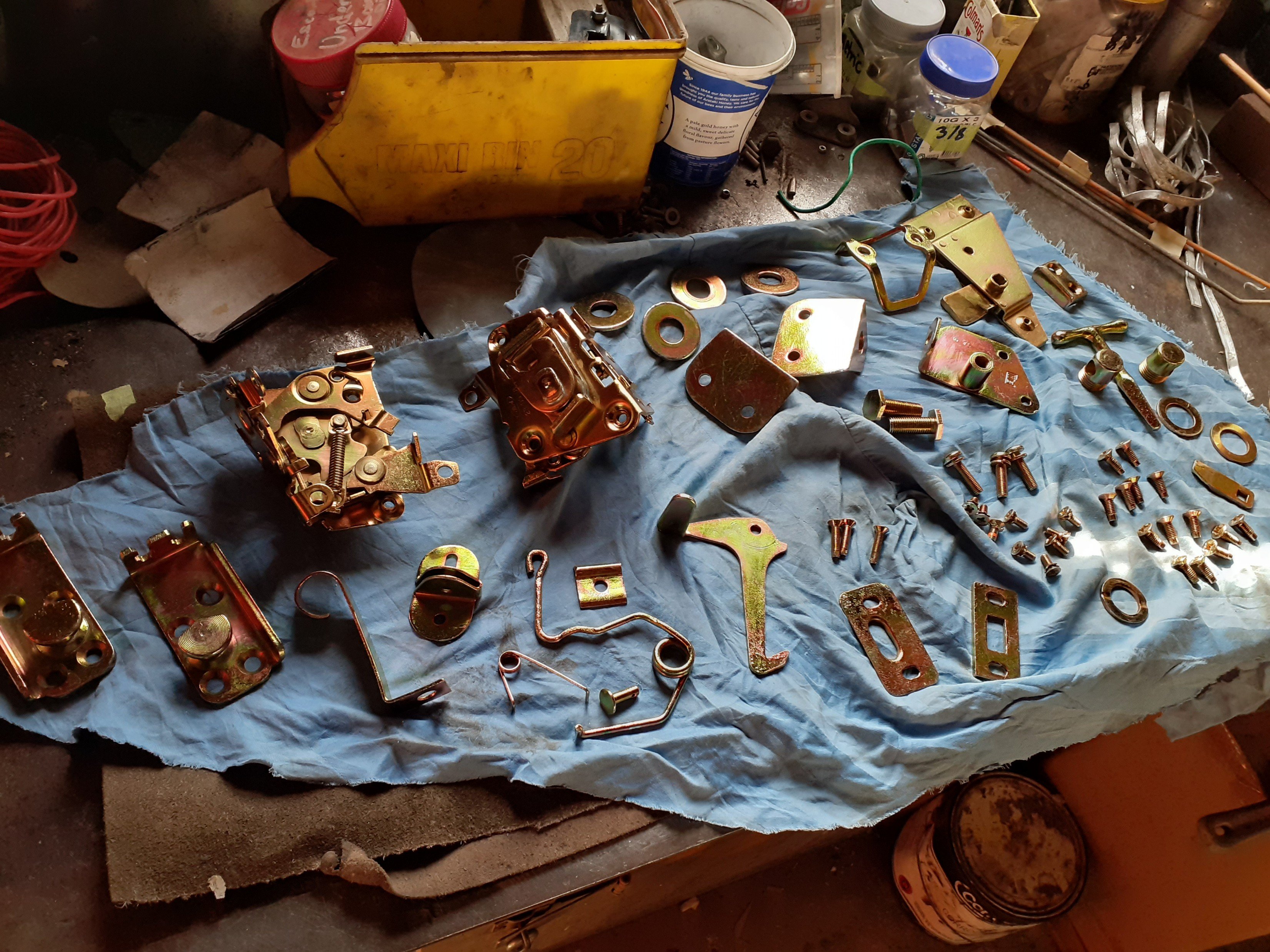
Something something gold. Few dress up pieces.
1 point
-
Yes.1 point
-
Shit yeah, this will be cool! After having not seen clapped out R32s driving on the streets for the last 5 or so years, I've got a renewed appreciation for how nice the shape is. What's the gearbox situation like, is the factory box going to be happy with RB30?1 point
-
need to get @Dolan involved in this one.1 point
-
A bunch of layers with a headgasket between each1 point
-
How's the tally going Dave, are we in billet block territory yet?1 point
-
New level of 'its to far gone', to anyone else 'parts car' but to you 'ah just a little bit of rust' - Your work is awesome man.1 point
-
I guess the right time to have fitted those stronger rods was yesterday1 point
-
My dear wife gets bored sometimes and then puts her mind to ways of highlighting my vehicular acquisition habits with a particular sarcastic bent. She has produced this “helpful” flowchart for me.
1 point
-
I'm excited for exhaust stuff. I think you will see big gains. Anecdotally, my x1/9 sounded amazing when I put 40s on it but wasn't really all that much gruntier. Then I made some headers based roughly off the Guy Croft opinion spec, although smaller pipe sizes cos it wasn't a race engine and I wanted it to fit the bodywork, and I immediately gained 800-900 revs and a big increase in livelyness all around. So yea, make it happen ....1 point
-
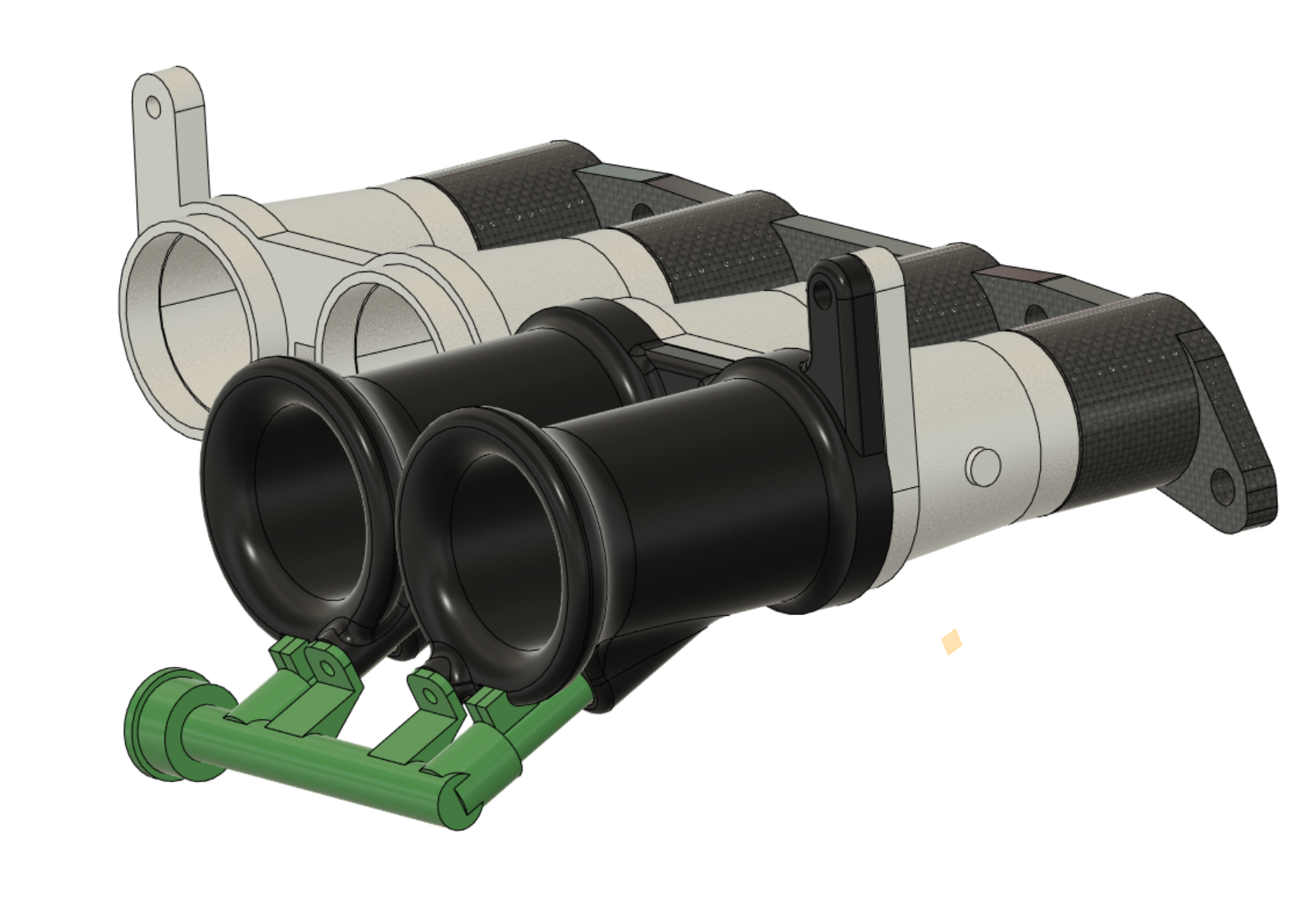
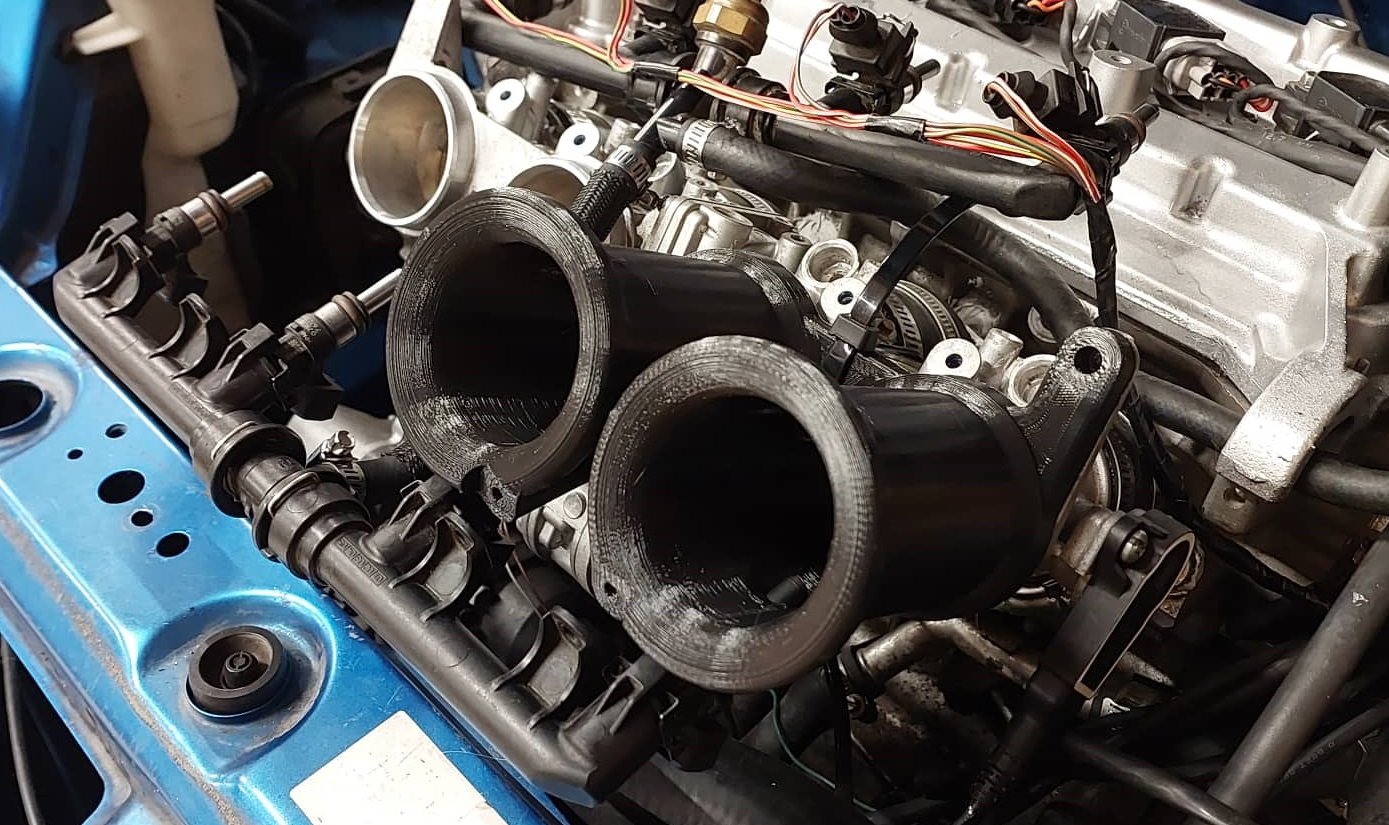
Big trumpets sticking out the bonnet will be a 1 way ticket to green sticker haha. I should have a new version with bonnet compatible extra length, ready to go by tomorrow night though. These ones are rotated on 45 degree angle in order to try get as much length in as I can. Then about 130 deg of bend or something like that. Hopefully these indicate that they are "too long" as my life is easier if I can fit straight ones. But if they make good power then cant complain! No outer injectors but will try get the runner length right first. Will also try borrow the @Stu Science(tm) tig welder soonish and have a go at splooging together a mild steel exhaust.
1 point
-
The not-engine bay is looking tidier, found a better hose combo so the cooling system at the front is ready. Hose clamps are longer than I like but what evs. I got the fan mounted and wired in, I won't bother with a shroud just yet though. Next up, more ugly temporary bracketry. It took a bit of fiddling to find a good position for the oil cooler in the vent hole, it had to line up with the body so each of its three mounts are different but it can be removed assembled which is handy.1 point
-
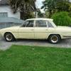
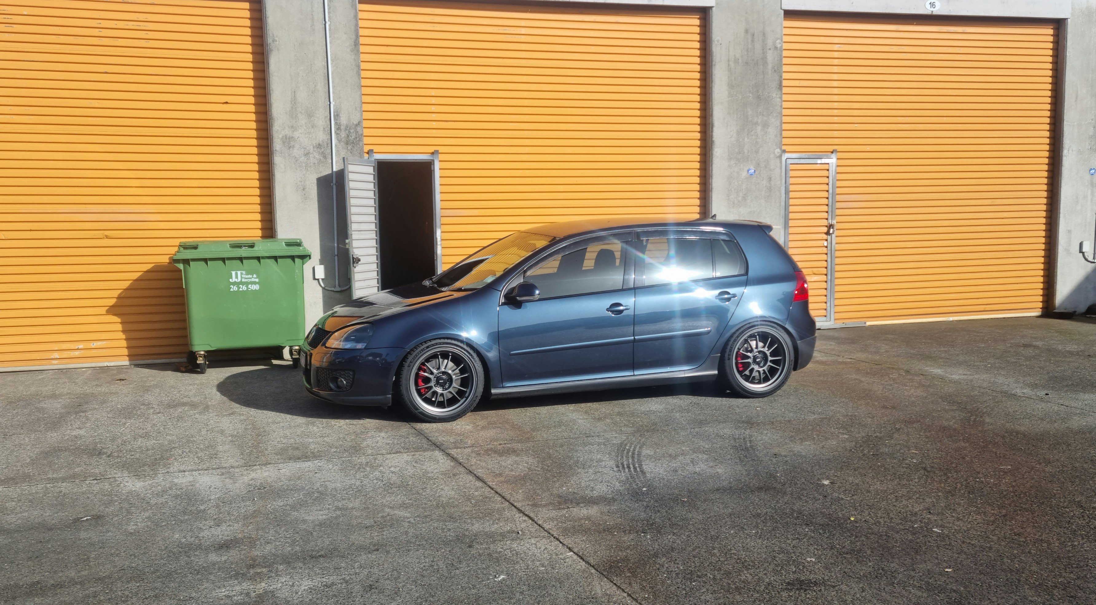
Coilovers in 25mm drop all round Looks bang on to me New exhaust in aswell and its not that loud just bit deeper tone and gear changes sound bit sweeter
1 point
-
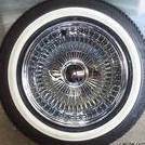
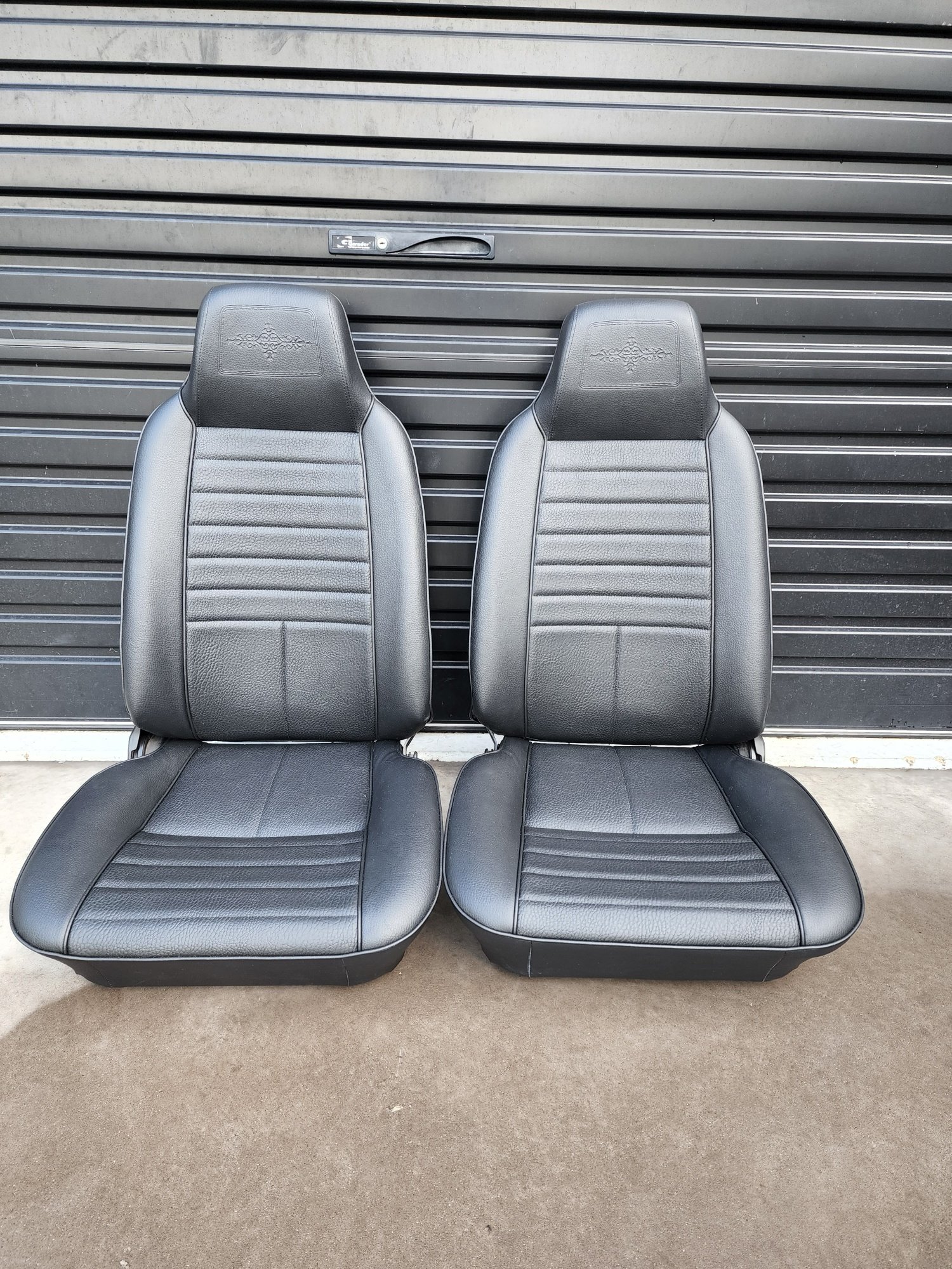
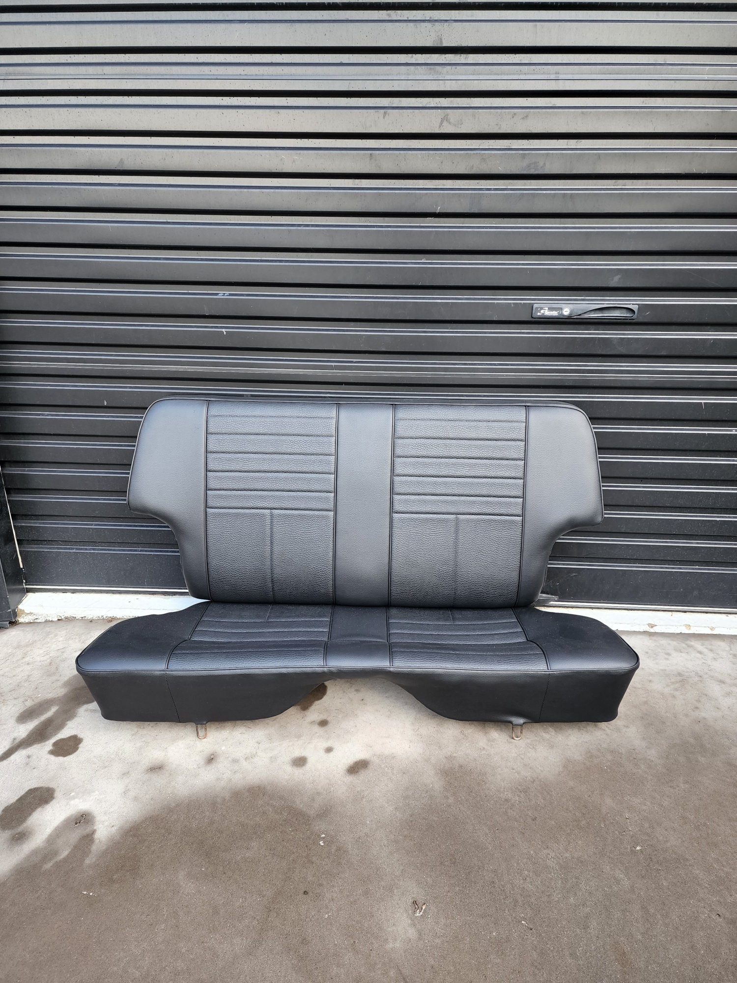
Have just had Kaz at KP Upholstery retrim the factory seats i had that had been covered in some sort of velvet material in a past life ha. Picked them up today along with the doorcards. Vast improvement! Very happy how they have turned out, He has recreated the factory interior style which will look the part im sure!
1 point
-
I ran my dereg'd Hilux through VTNZ for a compliance check. I had the chassis recently painted prior to the check, it did have some minor cab damage that had been repaired but was noticeable. The inspector simply requested a structural repair cert for the vehicle to comply. So I'd recommend not to get to carried away with paint and put it through the check as is1 point
-
Toyota Echo Intake version 6 million As per previous waffling I think it will be beneficial from a reflected wave perspective to keep the intake runners more parallel most of the way up... Then also make them a bit longer. So I modelled this up. So this then had the flow on effect of making the fuel rail situation a little tidier as well, as it pokes in from the other side. So just use the regular tabs on the fuel rail for holding it in place. Also keeps more of the perimeter unobstructed, which might be important now tha the cross sectional area at the entrance is greatly reduced. Also now the fuel line and the injector plugs are flipping upside down too, so it will look a lot less messy. First iteration needs some dimensional changes to fit properly but so far so good. It's got about 10mm clearance the the bonnet which is perhaps a little marginal. (because of longer runners) But see how it goes. I still havent figured out how to print the nylon stuff properly yet, might need to wait until I've got some $$ to buy a dehydrator box. But I'll try get the design sorted in PLA for the moment anyway.
1 point
-
Time to mount up. First thing was to remove the air from the nearside chassis rail. It was a bit frilly right where I want to bolt a crossmember.. I bought some bobbin style rubber mounts, 60 in hardness, from the local engineering shop. They are British made mounts so somehow they will probably leak. I cut some plates that then bolted to the stock Subaru gearbox mount points. Then shuffled the engine/box into the position I wanted it to sit. I had measured the level at which Imp one sat on the ground, finding that the bottom of the rear side windows were pretty much level. I set Imp two up on the hoist at the same level and made sure it was level across the car. Marked things, measured things, checked clearances. Once happy with all that I got some cardboard and started making little shapes with folds out of it. Added a bobbin and the other end went through the original Imp gearbox chassis mount, hole enlarged a mm to take a 10mm stud. Kept trying them until things looked good and transferred the shape to steel. Bent the shape in the... bender. Tacked in place.. Removed to be reinforced and fully welded.. Finished and fitted... Now for the front of the engine. Or is that the back of the engine? The other end. I plonked a bit of steel in place. I didn't want to go much lower than the sump. I went for some low profile bobbins that were ideal. Cut some more plate to suit and drilled, tapped, bolted them in place on the engine end plate. Played with more cardboard and then steel, folded and tacked till I had things that held bobbins. welded them up.. Next job was to make a crossmember. Now there was going to be lots of moving this engine/box in and out of position. Not just now while building the crossmember but in the future of the build as I do exhausts/piping/induction etc. The huge steel bench we have in the workshop that I had been moving the engine in and out on was just that - huge, heavy and often in the way. Plus its set in height so when I wanted to move the engine position up and down it was via the car hoist which is not exactly finely controlled. I needed a bespoke engine table that was easily height adjustable. Enter stage left the 'Engine cart 2000'.. I whipped that lot above in one evening using an old height adjustable Bedford truck seat base, some spare steel offcuts from the steel rack and some budget castor wheels from Mitre 10. I added some plywood for the top and then I sat on it whilst twiddling the knob - which made things go up. And down. It was designed to match up with the main workbench in height so I could slide the engine and box straight on. Engine and box are quite light as they are and I can shift them about easily but that wont last when the flywheel/clutch/pistons/heads/gearbox internals are all back in their rightful homes. I painted it grey because I don't like blue steel and Mitre 10 had loads of plasticoat spray paint on clearance. I couldn't help but mask the old sticker on the seat base.. Hannah varnished the plywood so it looked pretty. But then I realised that sliding the engine off and on was going to ruin the ply, nor was plywood a very slidey surface. So a bit of old stainless kitchen bench got cut up for the top layer. Now in action.. Aint that just so cute. Way easier to move the lot about the workshop and into position under the car- which now handily sits a bit higher in the air which was nice for the next stage. Crossmember time. I wanted this to be more organic/factory looking then the simple box section one holding the Datsun up. It had to be strong and allow plenty of space for exhaust pipes heading backwards to a silencer assembly that will be slung under the rear valence. It also had remove easily from the car, ideally still attached to the engine if need be. I started by making some mount points that would bolt in and out easily onto the chassis rails. Captive nuts welded on some angle iron that sits on the inside of the rails. 4 bolts per side. These bolted in place with 3mm alloy spacers on each side to allow for differences between this car and Imp one, which I know has rails a few mm closer. Plasma cut a strip 50mm wide from 3mm mild steel plate. Welded some mounts on it to suit the bobbins hanging from the engine. Bent a curve in the plate till it sat where I wanted and had the shape I desired. Then started cutting cardboard again... and transferring it to steel... Tacked it altogether.. Added tubes to it for easy access to the engine mount nuts which made for a cleaner look. I could close off the angles on top and make it all pretty like. I welded what I could on the inside of the crossmember. I really didn't want exposed welds on the outside or any lumps. Then welded the outside. I had to be strategic because even though it was all 3mm steel it would still move a heap as the welds cooled- shrink on the welded edge and shorten or lengthen the whole length either way. My final welds had to pull it back out in length as they cooled and shrunk so it matched the rails. To much relief I got it pretty much bang on and it all still lined up sweet. The whole time I was building this bugger I was thinking 'ooh this is going to be hefty..' and stressing. Trying to find a happy medium between strength and weight but strength really was the most important thing. I didn't want my engine to fall on the road. As it was it turned out ok. Not a bad weight at all. I hung it on some scales.. Not bad at all. Just a smidge heavier than the alternator for example. Certainly brute enough. I was happy. I bolted the whole lot in place, lowered the wheely cart 2000 out of the way and there it sat, engine and box finally suspended on their own mounts. Beautiful I thought. So beautiful that I had to take the car off the hoist and snap some pics... Would ya look at that. Damn that looks cool. I was fucking stoked. This was a big occasion. I patted myself on the back and then took some more pics and measured some things.. Clearance under the car was great. The crossmember was only about 10mm lower than the exhaust on IMP one however this was also far further forward. It'll be gravy. The room between the inlet faces on the heads and what would be the underside of the parcel shelf was almost bang on what I had very originally measure it to be when I first mocked the untouched engine up under Imp one. About 170mm.. Neat. I'd better start ordering some induction goodies eh. So that's that. Engine is now a bolt in thing. When the time comes I'll be transferring this crossmember along with the suspension crossmember over to Impy one. But I'm a long way from that point. I put Imp two back on the hoist, gracefully rolled the engine cart 2000 back in place, 'UNBOLTED' the engine and box and rolled it away. Engine was slid back onto the bench and I am now going to look at making a custom alternator drive pulley and mounting the alternator (probably the old prelude/civic item I scored from the wreckers) I have also been looking into the exhaust. I'm doing some research and trying suss out what to do about headers. Either modifying what I have or making bespoke ones. But that's another story and will be my next instalment.1 point
-
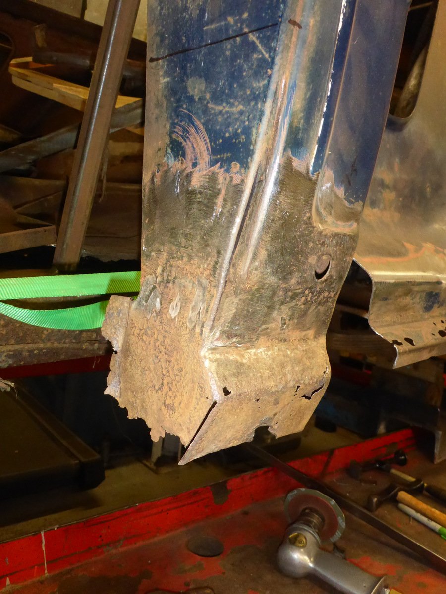
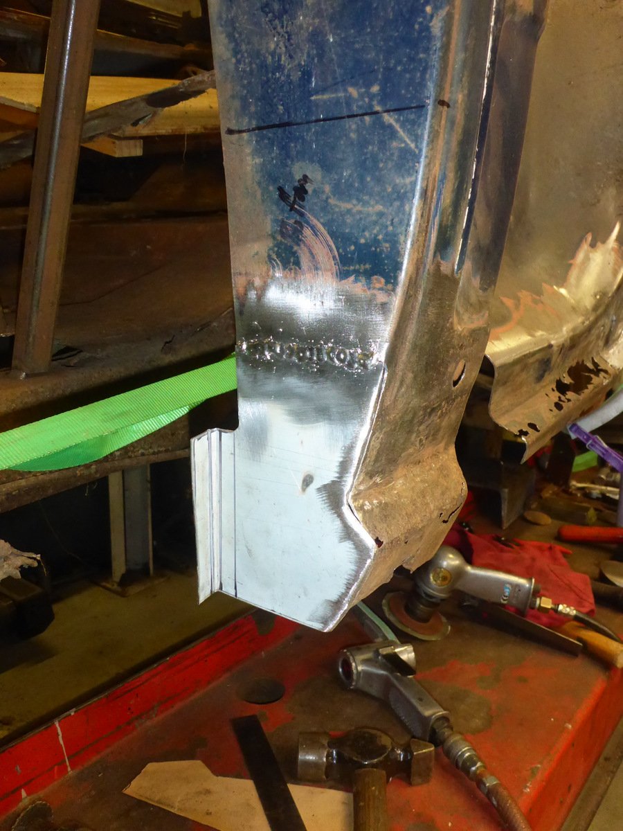
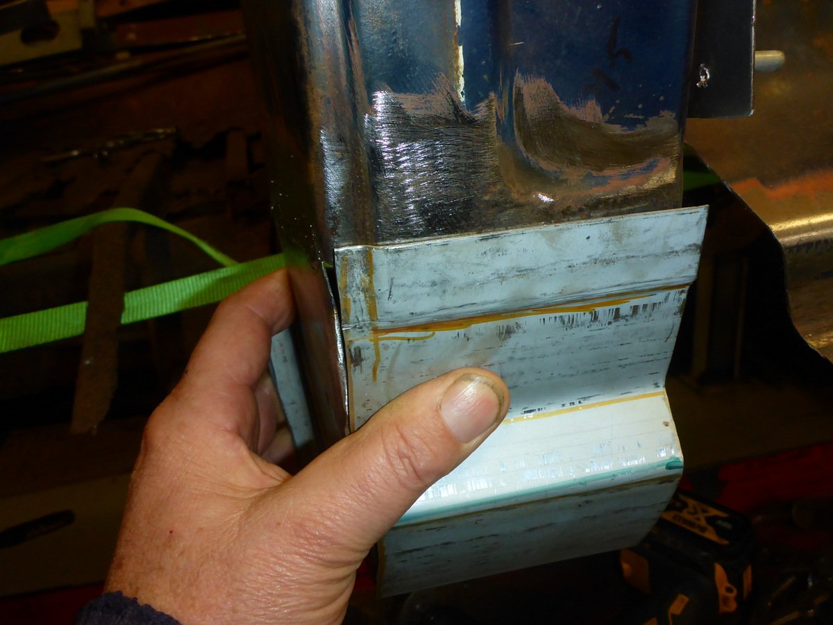
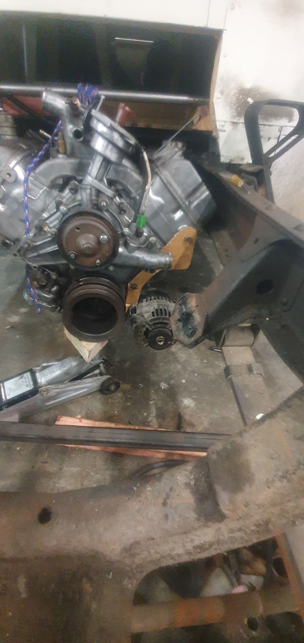
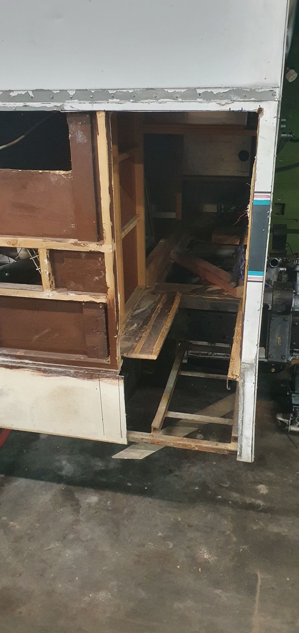
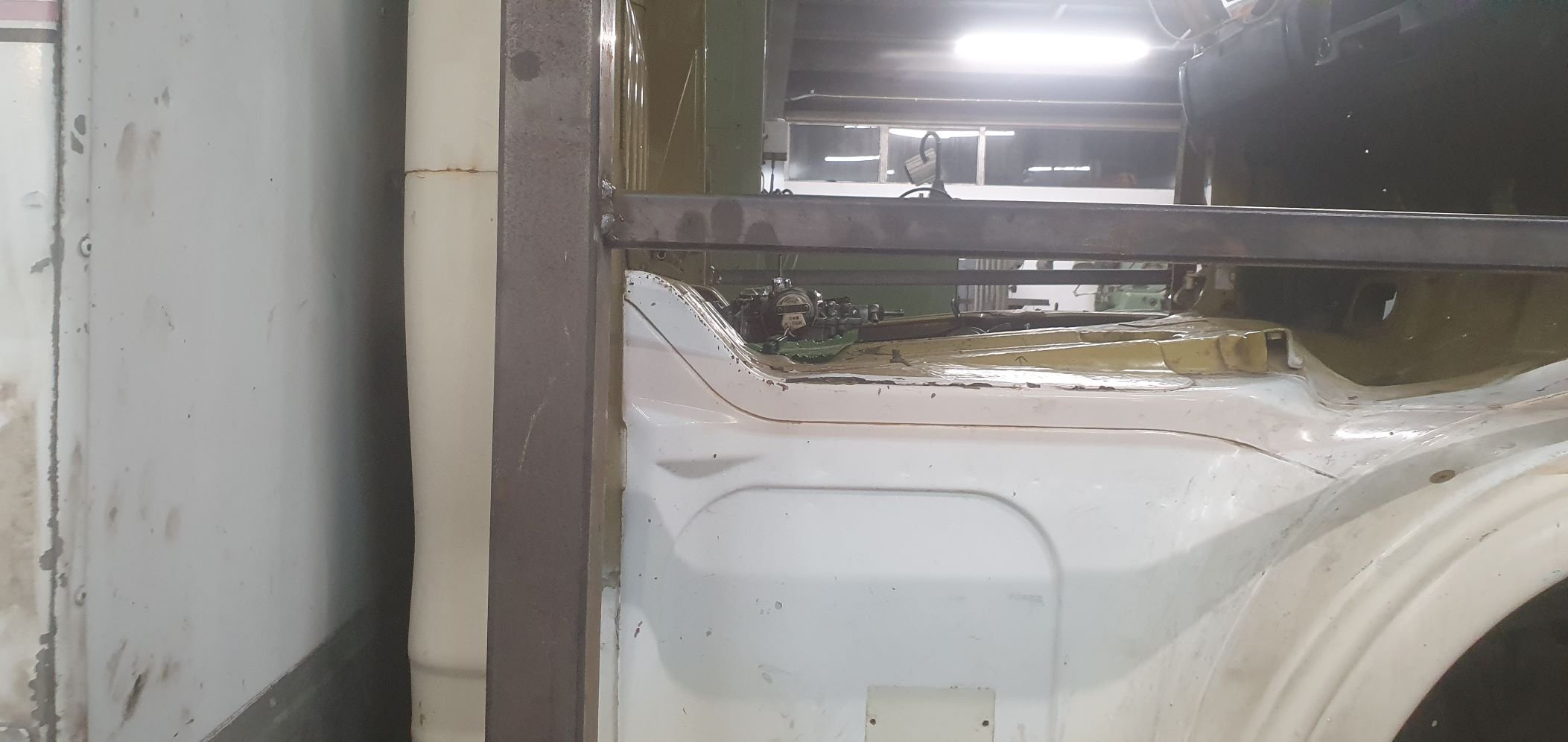
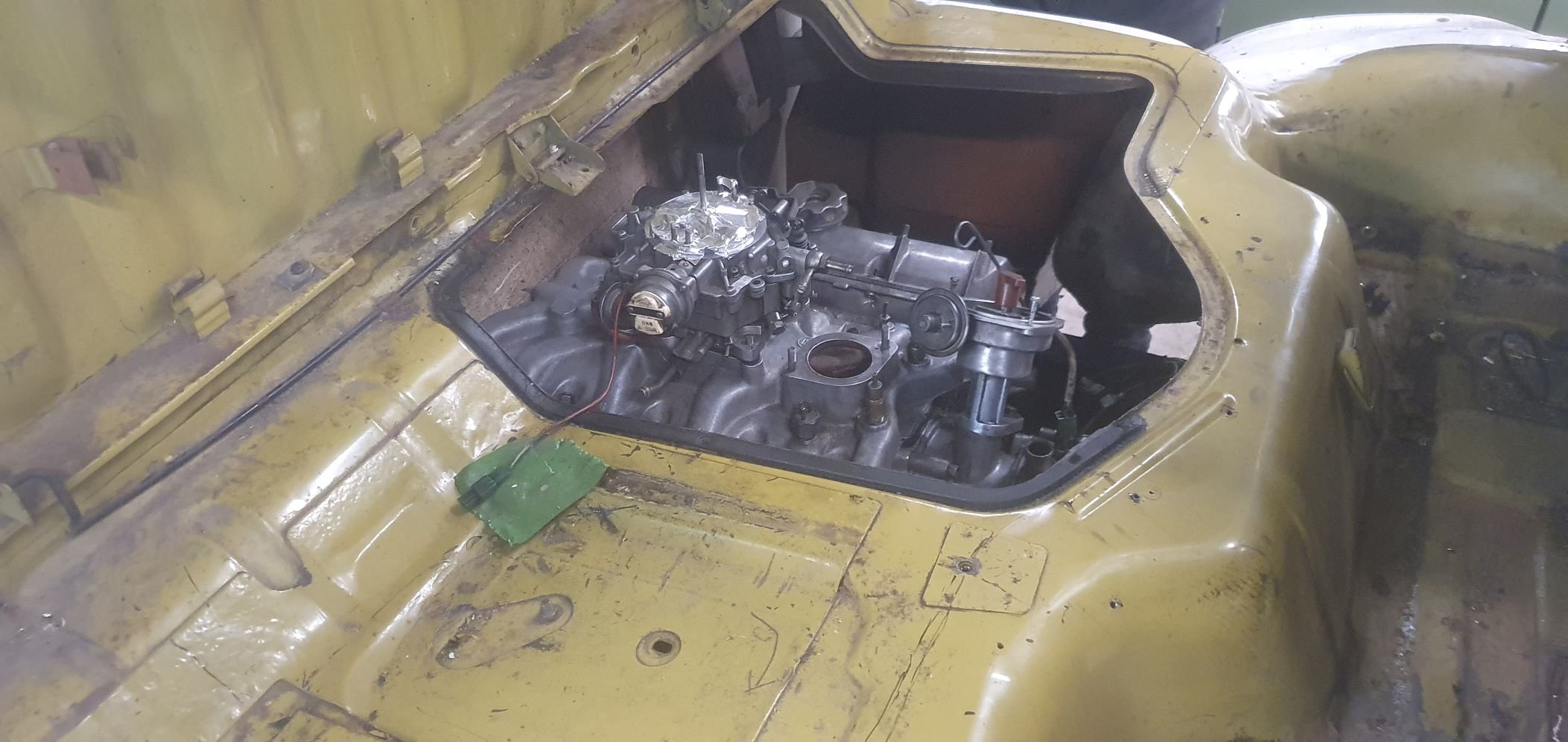
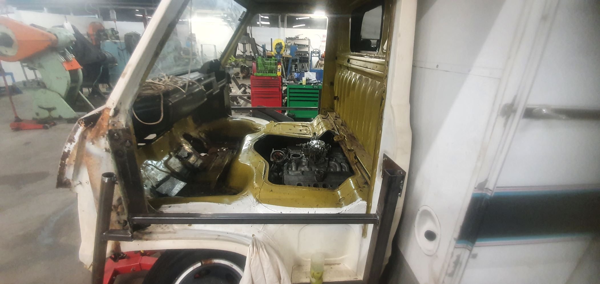
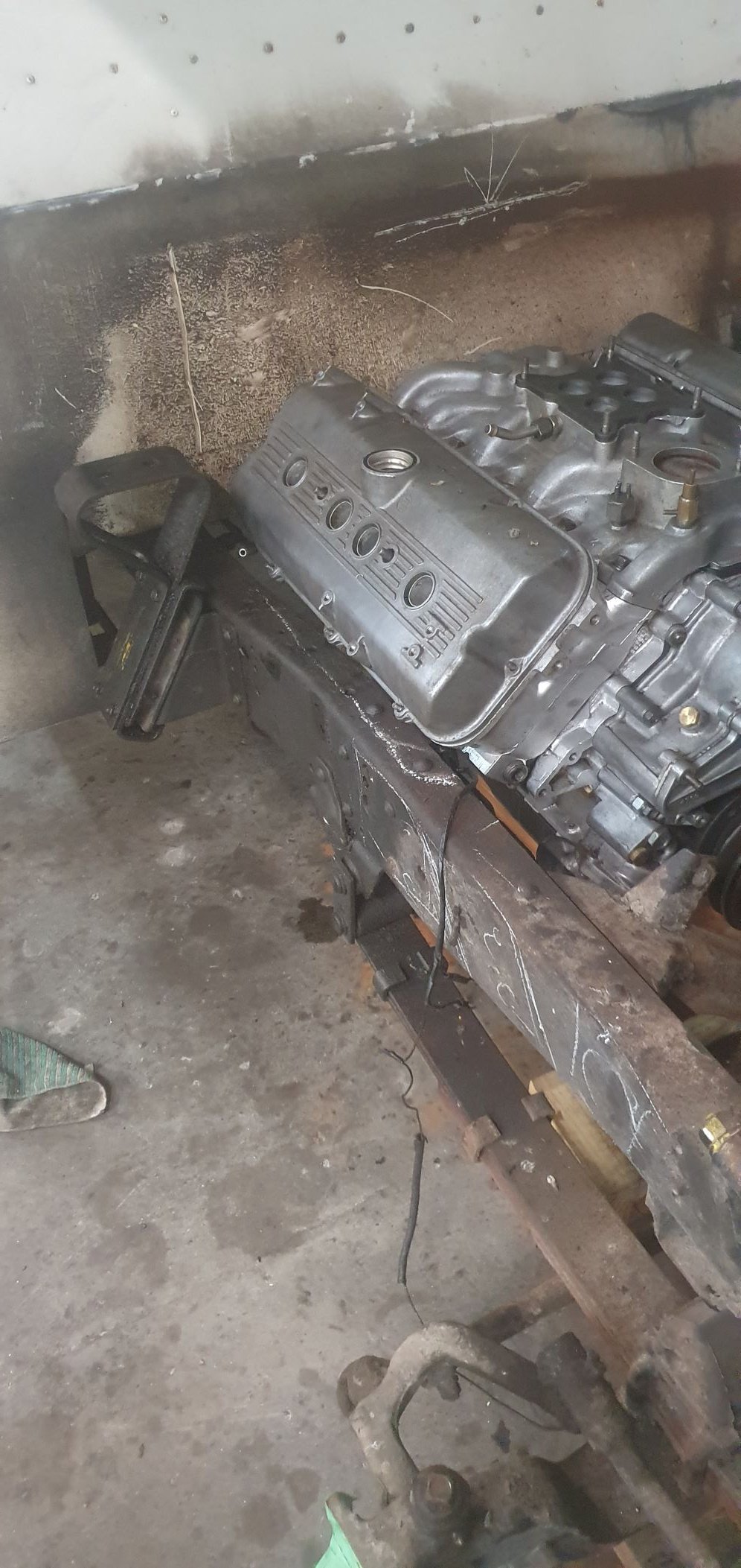
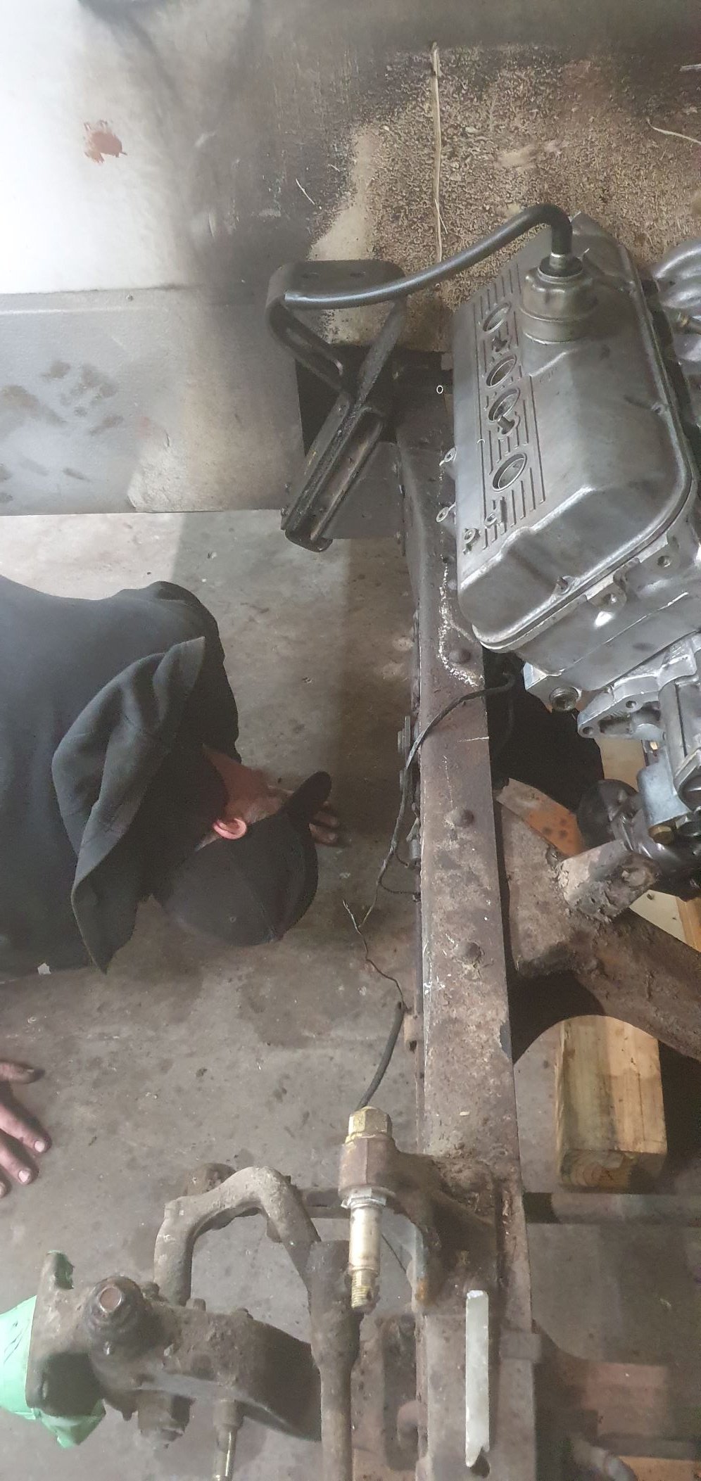
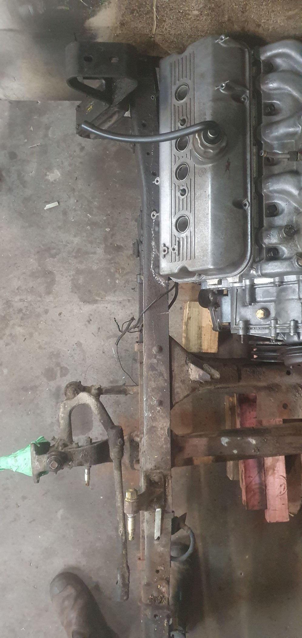
In terms of actual activity there is little to report, however the pondering, and opining from cunts like @ThePog and my worker - of near-equal cunt status - has been somewhat rampant. The main topic of conversation has over the last few days largely revolved around whether it is actually going to fit. It is largely a problem I have never encountered - just saying. So the motor has been sitting in the same position since we dumped it in there. I had to have a bit of a workshop tidy up. As many of you would well be familiar with, doing shit like this means sorting your shit out along the way and doing things in stages, so come assembly time you largely have all the shit in order, just requiring cleaning or a fufu can touch-up job. So I did that last night, and then suggested to Kyle that we wheel the cab back on, just to see (and to stop us thinking about the actual problems below). The carb had to be lifted off the engine to wheel the cab back over. But my oh my, doesnt it look pretty in the hole. Confirmed, It is Gynormous.. Also confirmed, the fucking thing is going to live in that hole regardless. Chassis chop, mid mound, fucking whadeva G. Every other possible engine option is shit in comparison, so that bit is solved. Now I need to solve the actual shit of ensuring whatever we do doesn't result in either a basket case chassis-hack job that will never be legal, or someones lunch being sucked out through their asshole by virtue of the carburetors somewhat prominent position inside the cabin. See pics - it is not optimal, the engine must go down in order for the carb to actually clear the engine cover and/or seat. The chassis rails actually widen where they pass under the camper body, and if they were that width in the engine bay we would already have that cunt mounted and half wired up - but alas that is not the case... So the present possible solutions are as follows; Option 1 - slice a 30mm ish slither out of the inside top of the chassis rails (removing some of top leg of C-channel), effectively continuing the inside line of the chassis rail (under camper body) further forward through to where the front of the engine is, then stepping in (see chalk marks). Then strengthening the Chassis with another plate on outside with folded edge to reinstate the 'beam strength' back into the chassis, or adding other folded piece over top extending further rearward and forward (kindof boxing the outside) This would allow the engine to drop down and maintain the current position. Tight set of log-style headers, removable from below should be achievable. FYI, Im an Industrial Designer by trade so drawing up, profile cutting, folding some shit, fabbing and modding the rails doesnt seem a terrible idea to me - but there are obviously rules and my cert man has already advised his 'preference' is for not modding the rails. I feel a CAD model is needed just to communicate my thinking further here.. Option 2 - start hacking out the camper body - this is effectively the area at floor level under the sink - possibly the most useless space in the entire camper. Making a removable section and shifting the motor back far enough (prob 250mm max further rearward of current position or roughly half of the engine under the camper body. Driveshaft gets rather short, as believe it or not the wheelbase of this thing is a tad under 3 metres. This area will need a massage anyway for the trans, so there is some logic in cutting here now and then reinstating removable infrastructure later for trans access etc - regardless of where the engine ends up - ie it would allow us to fully entertain that possibility. Doing this means the engine slots between the rails somewhat easier, but obviously engine access becomes more limited and opening the engine access hatch means the engine wont really be that accessible (prob dipstick, dizzy etc access but little else). And it will look weird - I like the idea of opening that hatch and there she is in all her glory.. Added bonus is there will effectively be a 'Frunk' under the seats where the engine once sat... Option 3 - the oldschool hivemind give me your opinions on my discussion thread - maybe there is something I am missing here. Its hard to communicate how tight it is, hopefully the pics below tell the full story. Be great to hear others thoughts on what is possible here - I am actually also thinking of talking to one of the local Truck Chassis mod dudes too - given this thing is actually just a truck.. Chur.
1 point
-
Drove 2GRFE family wagon from Nelson to Hanmer yesterday, 7.0L/100km is pretty respectable. Now that we have Milly the K11 it doesn't get driven around town at all.1 point
-
Next step in the puzzle was to sort out a clutch release system. I had a couple of options that could work. I could use the stock Subaru fork but it was not ideal for two reasons ; 1: It would need a the release bearing carrier adapting to take a larger diameter bearing that would suit the Honda pressure plate fingers. 2: Its pivot location, being a centre mounted fulcrum point, would require a slave cylinder that pushed it towards the front of the car. This is because originally the Leone the transmission came from uses a clutch cable. I'd being using a hydraulic slave and it would have to be mounted up high, over the engine. Probably clash with the underside of the parcel shelf and would definitely look ugly there. Option two was to use the Ford Mundano concentric slave cylinder I have had stashed away for ages, acquired with the Duratec engine I was going to fit into the Viva wagon many moons ago. This certainly seemed the most sensible option because it fitted into the location almost perfectly... The pipes even pop out through the Subaru release fork hole like it was made for it... But it was still going to require a little work. First off is that it has a flat bearing face, made to suit curved diaphragm spring ends. It was also too small in diameter to suit the fingers. So a lump of steel was plucked from the store... There was just enough room between the bearing face and the 'slidey hub' bit that the bearing hydraulics slide in and out on for me to machine a locating stub onto the bit of steel... With that being a perfect fitting locating point the other side was machined with a radialised face to suit the flat fingers. The end result looks like this.. This will be stuck in place onto the release bearing face with something like loctite 601. It cant go anywhere anyway. Next issue was fixing this whole unit in place and making sure its dead square to the input shaft centre line. Luckily the units bore was larger that the stub/shaft?* that the Subaru release bearing carrier slides on by about 2mm. It also so happened that when pushed on as far as it would go it allowed for just the right amount of movement of the release bearing, plus a bit to spare. So I machined a thin sleeve with a lip at one end to suit.. This I made a nice snug fit onto the stub/shaft thing and the Mundano assembly slides in place snug, thus making sure it all remains square. I assembled the lot together and checked it all with the transmission bolted in place. Looks good.. The initial throw of the release bearing will be adjusted at the pedal, which will now require me to either use the Mundano master cylinder (plastic..yuck) or machine/ sleeve my Imp one (actually the same as a landrover/most trailer brakes out there..) to suit. I'll look at that when I get to it. Next step is to bolt the assembly in place. The Leone box has splines cast in around the stub base... ..but luckily enough room between them to glue some blocks in place so I machined some alloy down to suit.. Because I knew the assembly was perfectly straight and in line I just needed to give enough clearance on the blocks to allow for some epoxy. I drilled and tapped the blocks to suit, mixed up some of my favourite JB weld and filled the chosen cavities then slide it back in place. Then let it set overnight.. The next day I tried the original Mundano rubber boot for the pipe exit. It almost fitted. I sliced 5mm out of its width and it was sorted. Not perfect looking but it works and cant be seen once the engine is in place anyway... Phew. Done. At this point I really did have a feeling like I had made it past the trickiest bits of the engine work required. But for some possible baffles around the oil pump pick up and maybe an anti surge plate (not that the Goldwing engine has any as stock) I think all the required mods to the engine are done. I felt like having a cold beer. So I did. Then pondered the next jobs to do. Which was to look at where I would run my cooling pipes and finalise the position of the oil filler tube.. In order to properly work through some routing ideas I had to plonk the heads back on. With them in place I might as well have some fun, bolt the transmission on and stand back with my beer and gaze at it all. I took some pics. I'm pretty bloody happy with it how it looks and I really did get a mojo boost looking at it sitting there as a complete unit waiting to go in... Its so neat and compact for a flat six.. Man I'm looking forward to having this setup in the back of my Imp! What's nice to think about is that while there's still a big load of work to do these next jobs will be super fun. I'm especially looking forward to making the ITB arrangement to suit and doing my best to create a really clean looking engine bay.1 point
-
Back on the chain gang ! Yep. I'm back into this project. Its been a hectic busy last few months. Well for me, but others would probably laugh at my work levels. The last update was in September and both Hannah and I were pretty busy building a custom coffee cart for a customer. It was a fair old mission not helped by that pesky lockdown stalling a load of stuff ordered, including some double glazed window materials from Auckland. We put in some hard efforts to get the thing built and ready in time for the agreed date and managed it with a 2am finish on the last day before delivery. I was well chuffed with the cart we built and the customer is soooo happy with her new cafe ! All fully insulated, huge windows that roll away into the walls, loads of stainless benching and a lovely outside wood framing we made using Eucalyptus timber then oiled. Here's some pics of the build... Phew. Check that one off the whiteboard of jobs. Loads more work to chip through and we are now onto the steel framework for a local ladies housetruck. So I am going to do my best to just put down the tools, lock my bicycles away so I cant be tempted to just go riding and instead do more on this engine swap. Most recent bits I have done are as follows. I wanted to finish off the oil system. The internal stuff from the pick up to the pump and filter was sorted. Now I needed to get the oil from the filter to the engine. Luckily, well I kind of planned around it, there is a hole left where gear selector shaft went. This was ideal to pass a pipe back from the filter block outlet towards the front/belt end of the engine. But it needed to be bigger with some clearance. One big drill bit later... next up was a plate to cover the front. What used to be here was a cast front cover, much deeper obviously because I have lopped off a huge chunk of engine casing. It housed the oil filter, now moved to the side. Instead of that I now needed a flat plate of thick alloy that will serve several things. The engine mounts, most likely typical compression bobbins, will be mounted off it. There has to be a way to get the oil from the pipe coming from the filter block to head back into the main oil feed hole higher in the block. Finally I need somewhere to put oil into the engine and also to check the oil level. I started with a plate of alloy I roughly cut to size. Drilled it to suit the holes in the block that the old front cover mounted to. I then drilled a hole in it to suit the oil feed pipe. This was a hole perfectly located to make sure the pipe would line up with the filter transfer block nice and square. Because I'm using the O rings that Honda used throughout the original system. There is a small tolerance for being out of square with these but I might as well get it as close as I can. I then needed to make a bolt on block that would take the oil from this pipe end and direct it through another hole in the plate which locates right over another O ring sealed port into the engines main oil way, just as the original front cover did. I started with some more chunks of alloy and made a thousands of teeny tiny chunks of alloy with the tablesaw... One of the blocks was then milled out to suit the pipe outlet and oilway inlet sizes. I also used a tiny little slot drill to add a groove to help keep the sealant in place.. Flipped it over and took more material away. Added some cooling grooves. But really.. come on. They were more just so it looked a bit nicer than just being a lump of alloy. Why not.. Clamped it down onto the front plate and drilled mounting holes... There's a nice amount of room to still use the original honda cooling hose if I want but I may well do something else when I get to that bit- depends on my cross member design and engine mounts etc.. Next up was how to get oil in place! I needed a filler point. The original filler and dipstick are in the wrong spot and kind of chopped out. I could have made a dipstick to suit the now chopped down dipstick housing but that's at the rear/flywheel end of the engine. With the engine turned round 180 degrees that puts it under the parcel shelf and would mean reaching over what ever induction setup I use (cough*ITBS*cough) so that's not cricket. A filler tube, right at the front, but actually now the back, of the engine with a combined dipstick under the cap made more sense. I rummaged through my collection of alloy.. Playtime in the lathe... and out popped this... ..into which oil will pour as such.... Now I needed some more bits to hold it in the right place so I made these flanges to suit more pipe. Once I know what I'm doing with the cooling pipes etc I'll cut the pipe to suit and epoxy it into the flanges. I ideally need the main large flange to bolt over a hole below the oil level height - which I have roughly worked out allowing for about 4.5 litres thereabouts. This pipe and cap will be right there, on view, easy to get to at the engine bay opening. The two smaller flanges are so I can remove the upright pipe to allow for the cambelt covers to be removed, or so its not there liable for getting damaged when removing and moving the engine about. I did think about being super silly and adding a sight glass to the pipe. Or use some thin glass or plastic tube. I then even thought about being really silly and adding an led light into the pipe to light up the oil. But oil does not stay honey clean does it. So a neat little dipstick under the cap will do. Lastly I needed to bolt the sump cover in place. I had to think carefully about bolt placement for sealing purposes and get the bolts square. This sump plate is going to have to be sealed well because there is no usual high sided sump like most cars. Hence I built it rigid to help against flex. Good quality sealant will be the order of the day* To get the bolt holes square I had to do this... Impy sat outside looking in at his new heart being crafted (said like some car obsessed bloke who anthropomorphises his cars)... Well then. That's it. Crikey. Another wall of text. I hope you enjoyed my ramblings. I promise I'll put more effort into working on this (but it is summer after all..) *It will leak. Its a British car. Its destined to leak.1 point
-
Chassis update. My Dads been working away on this in his spare time. Many press tools, dies, hammering and probably injuries later a chassis rail is formed! Looks like the real deal! Pretty impressive. The other side should be a lot easier, so he says This is how you make a 40Ton backyard press to do some final tweaking.1 point
-
Talked with Michael Anderson from the Bugatti Club Australia a few months back. Good guy to talk to. Heres a copy of the article for those interested. Originally published in The Bugatti Bulletin Vol 73, August 2021. Reproduced with the kind permission of Bugatti Club Australia Inc.1 point
-
Phew- been busy. Lots done = update time. But to save my sanity I might do it in two lots. So as per @GregT bit of information above I looked into motorbike oil pump chains and yeah- bugger all have tensioners and they actually run quite loose. I then decided to scrap the idea of spring loaded tensioners because even with the ones I had they were still a bit awkward to fit and didn't quite work in the angle I would have wanted. So enter stage left my new adjustable tensioner device... which fits like this... The bolts that clamp it down are actually accessible from below with the sump plate removed so once the chains wear to a point that I'm not happy with I can tension them independently. The will be nyloc nuts replacing those normal nuts on the tensioner bolts when the final assembly takes place. So with that finally finished I moved on down. The sump cover. It has to be fairly beefy because it could see some hits plus the engine will rest on it when on the bench. It has to be alloy so It can be used as a useful heat sink to pull heat from the oil. It has to look cool for when the Barries look under the car. So some fins were in order. I bought a big lump of alloy from Ulrich aluminium. That hurt. I put it through the old table saw and did some rough cuts just to save on time milling... Into the mill and did milly things. It was going to take bloody ages thought so I made a new tool which I shall call the DDC. 'Dewalt drill control' ... It could always be an MDC. Makita drill control. My cunning design is adaptable. In action... Groovy man... Then the sides taken down... I stopped there. The bit that is left unslotted will be machined to suit a recessed sump plug. I wont do any more until I finish the front cover below the cambelts where I'll also be adding some engine mount points. Next up was to finish the adaptor plate that connects the engine to the gearbox bellhousing. I had machined a bunch of pedestals to an exact length I had worked out to suit the positioning of the spigot shaft on the end of the first motion shaft into the spigot bearing. These pedestals have been machined on the gearbox end to locate within the dowel like spot faced bolt holes on the bellhousing. This way there was no chance of any float in any direction - the box would always be perfectly concentric to the engines crank and the bolts are really just clamping it. I bolted it all up together... Then cut some strips of 4mm alloy plate and started bending them to suit. Connecting the pedestals... Once I was happy with the fit up of those filler strips I ran a marker pen around them and took it all apart. Then cut the plate back to the lines in the bandsaw. Well I did so for a while but due to several things including the bandsaw having a totally rooted bearing collapse in the saws gearbox so making blade run off the driving wheel. plus the only course pitch blade having some missing teeth I ended up using the jigsaw. Anyway- got there in the end. Pieced it back together and it looked like this... Now time to weld it all together. I knew this was going to be tricky because the whole lot is like one huge heatsink and our current power cable to the workshop and the subsequent circuit breakers I have installed as a safety net wont allow me to run the welder at enough amps for such a mass of alloy - sit on 150 amps for any longer then 20 secs and it would trip. If I had a big enough oven I'd heat the whole lot up together nice and slowly. But I don't. So I just had to be strategic about it and work fast because once I stopped welding the heat soon dispersed. Luckily the welds just have to be strong and functional because it would all be smoothed down with a flap disc for a more factory casting look I wanted. It turned out good and best of all it hadn't warped so the box still fitted correctly and neatly. I was happy with that and it was now time to move on to the next stage which was the starter motor fitment. That will be in the next exciting instalment1 point

.jpg.cb3ebfc1eaccbf645391b12badd21f62.jpg)


.jpeg.1c307258ca1528654e536147620b1660.jpeg)


This leaderboard is set to Auckland/GMT+12:00