
Leaderboard


Popular Content
Showing content with the highest reputation on 09/12/23 in all areas
-
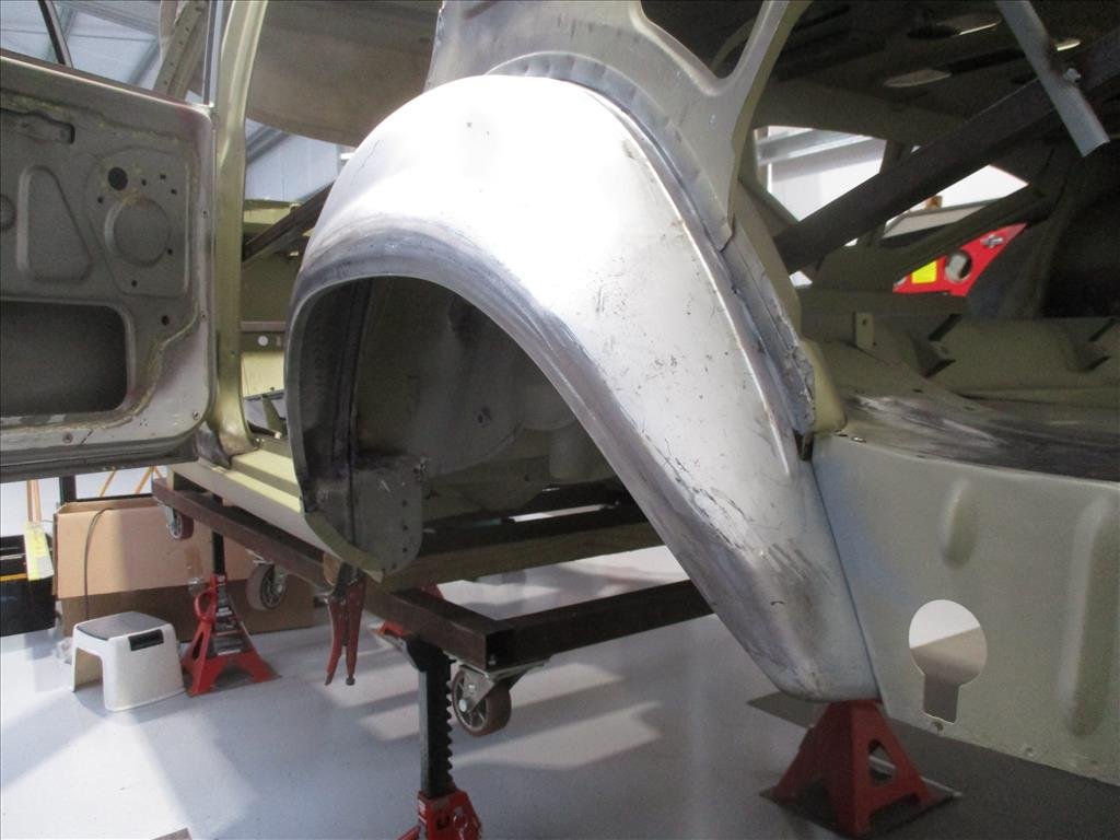
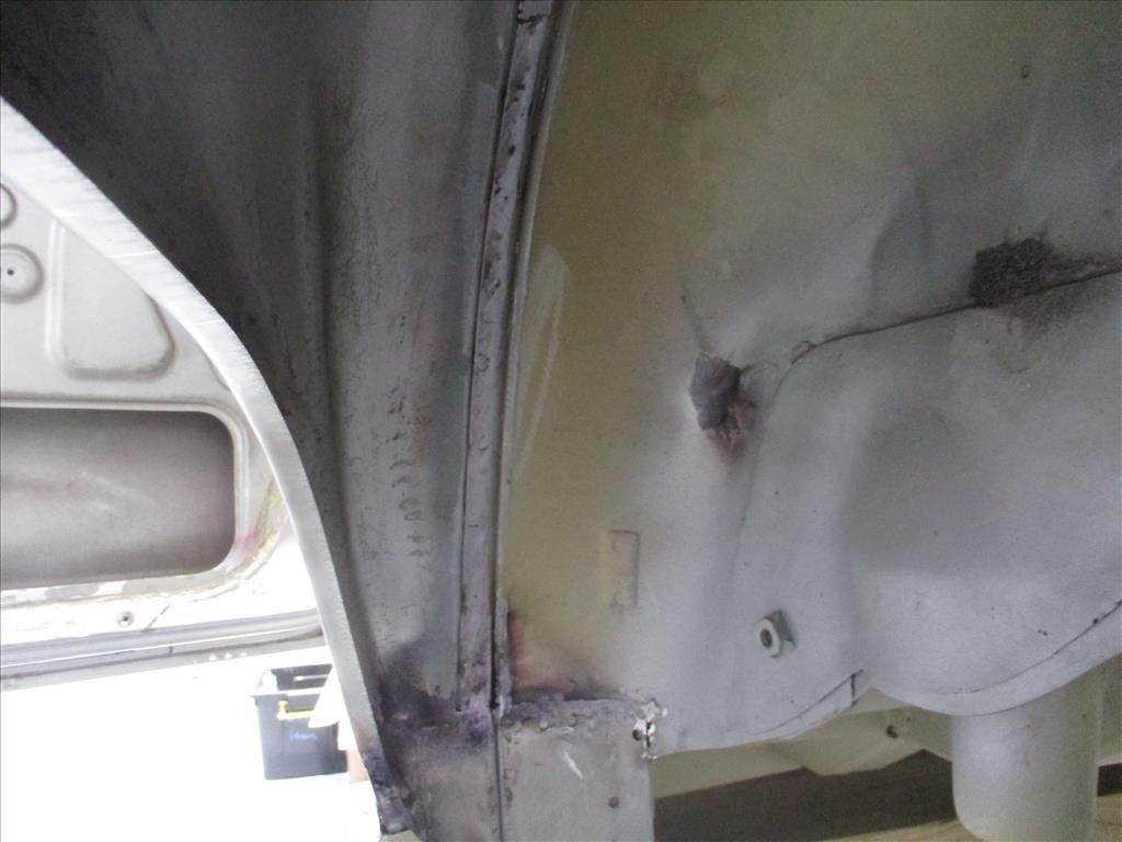
Fitted the body back on, the whole transmission tunnel needed to be raised up, so cut it right up and made a start by making the floor brace higher up. Made it in two sections, was pretty simple and easy enough to make. Since the diff was set up now I knew where the driveshaft sat in relation to the floor and could make the larger driveshaft tunnel (not that it had one to start with haha) For some reason someone hacked the inner rear fenders out. I guess it had some wide wheels on it at some point in it's life. This was the most dreaded job of the repairs I think. Made a patch and welded it it. Shouldn't really be able to tell once it's all undersealed. Now all the repairs were done and I heard the rumour that the local repair cert guy was retiring at the end of the year, I thought I had better get it off to VTNZ and get the vin number assigned to it and get the repairs signed off sooner rather than later. He came and had a check over it was was very happy. Bought a VE Commodore MRA fuel pump assembly. Seemed like the best, easiest and cheapest way about converting the tank to EFI. Has the correct pressure regulator, swirl pot and return all built in, so just the once hose coming out of it. Welded one steel ring into the fuel tank that incorporated an o-ring to seal against the housing and then a stainless steel ring to sandwich the pump down. It sits through the boot a little, so will have to make some sort of cover for it.22 points
-
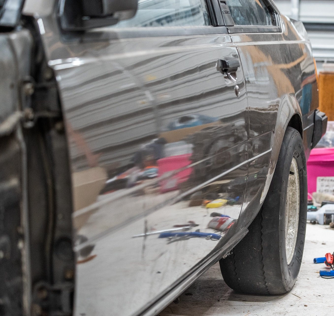
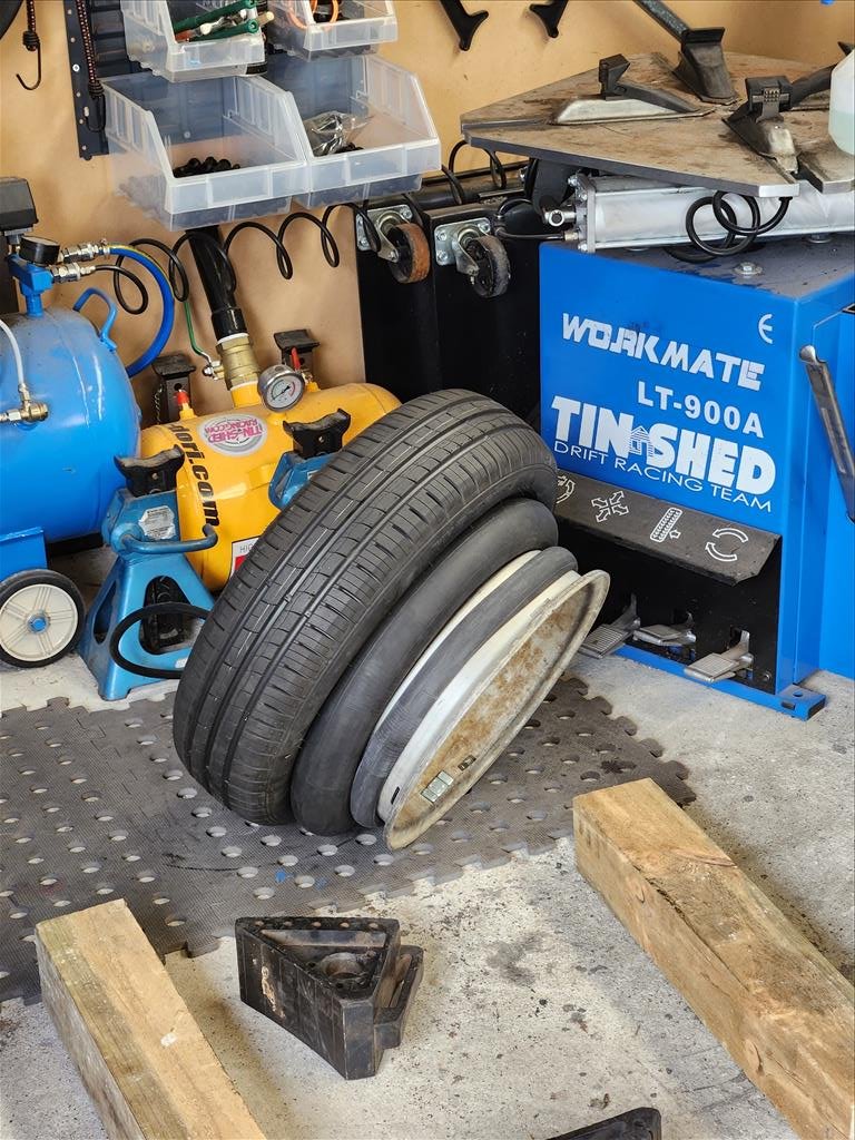
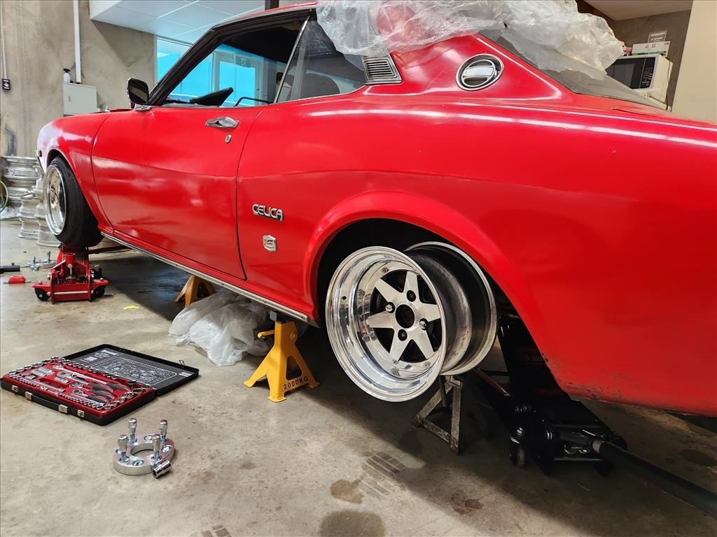
Surprisingly, my current rear brakes fit 13" wheels no problem! I did need to use the spacers to clear the calipers to face of the wheel though. I'm super hyped for drag racing activities! Looks sweet on trailer wheels and slicks. haha. I thought my mate with the 808 wagon was running 1.8 60ft on these same tyres, but he's run a few 1.6s. That is just an insanely fast launch. The best I've ever done in the Carina was a 2.5, best in the Echo on these slicks was 2.09. If I could get below 2.0 sec 60ft in this car I'd be stoked. I'm thinking I'll do my previous trick of extending the bump stops so that it's nearly sitting on them at its resting height, for drag stuff.
 15 points
 -
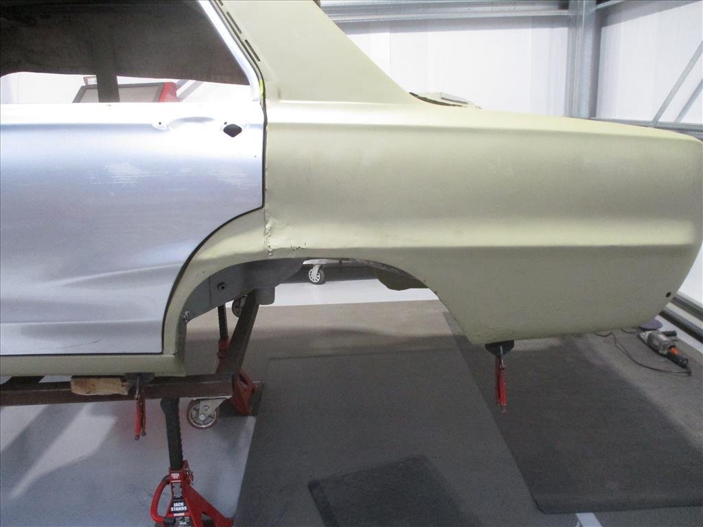
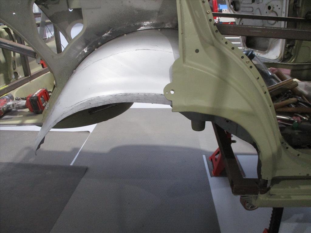
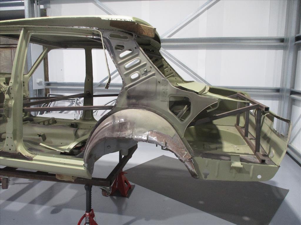
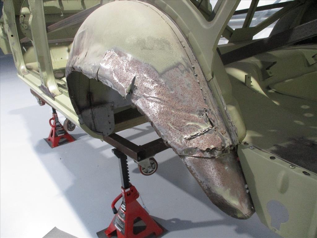
I was just thinking I haven't heard anything from panel Barry for a while and then bing, email arrives. He's been busy. Passenger side is pretty much buttoned up now, the outer rear quarter is not welded into place so still the little touches to go but man.. what an improvement! And just a reminder of what it was beforehand. He's already charging away on the driver side as well so shouldn't be too long then it can go back together in the back end.
12 points
-
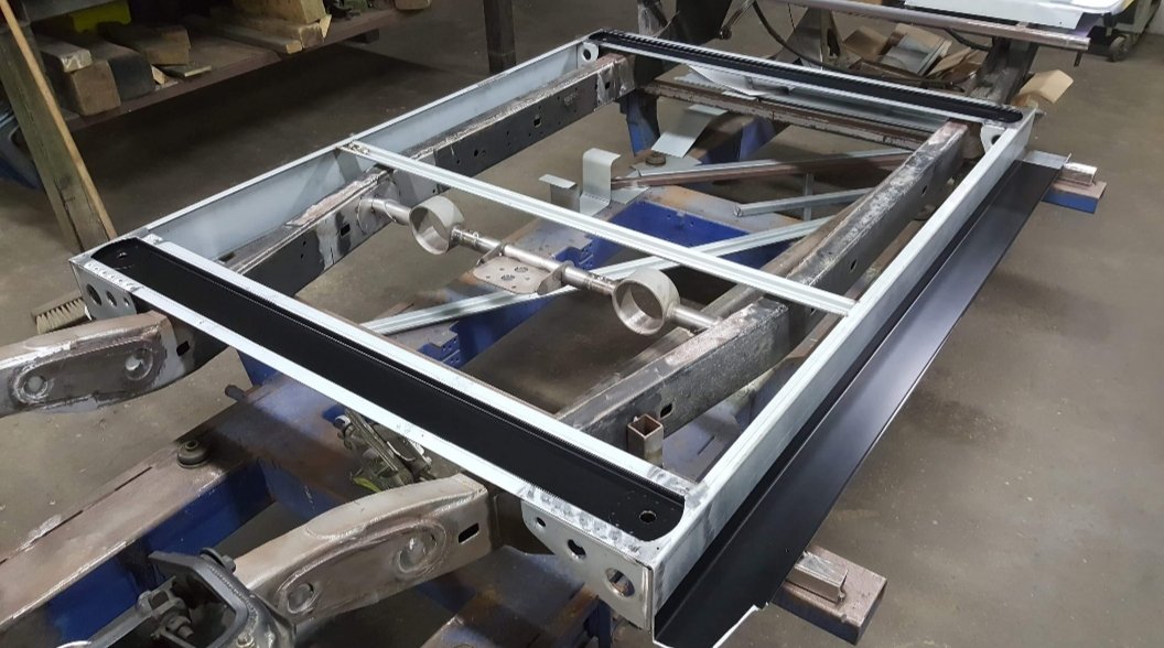
To make the pivot point for the Watts linkage I started with a piece of 38mm round bar and a twin row bearing. Milled a slot in it for the bearing to slip inside and bolt through. Then I drew up an arm in Solidworks, 3d printed and then got Dad to make a pattern to get it cast from aluminium. We had it heat treated to add some strength to it too. Bent and welded some 38mm rollcage tube on to the ends of the pivot boss. Made up some arms from some pipe, threaded bosses and rod ends. The whole process would of been a bit easier if I hadn't welded that crossmember so close to the back of the diff! This pic is fully laid out. And at ride height. Decided to strengthen up the lower rear arms. Tried pressing in the original style bushes, but gave up very quickly after they kept crushing the c-channel arms. Stupid design really! Welded in some bits of pipe and got some tophat style polyurethane bushes. Way nicer to use and same size as what I used on the Watts linkage. Also replaced the one in the upper arm with same bush.11 points
-
If it hadn't already spiraled out of control, this is probably the point where it did. Bought a 01 VX Commodore 5.7L LS1. Test fitted it in. Since the trans was swapped to a TH350 the driveshaft yoke and length worked perfectly. Also the aircon pump and alternator just have enough room to make work. Made some engine mounts. Used the same polyurethane bushes as what I used in the rear suspension to make it easy. Will add some more gussets to strengthen them up a little. Transmission mount the same bushes as well.10 points
-
Hello. This thread is about my dads Gsx1100. It was purchased new by my dad back on the 9/08/1985 after his friend Steve went out and bought a Suzuki katana 750 that was now faster than my dads bike of the time. It was the bike that my mum 1st meet my dad on after been asked to ride pillion on dads bike instead of his mate steves katana. To which previously my mum thought it was a big bike for a girl to be riding (dad had a huge plat). Turns out dad went fast with or with out a pillion and Steve didn't want to do that haha. as the love story goes, mum ended up with dad. they had me and the motorcycle was apart of my life growing up. me as a baby me growing up me having it as a birthday cake toy runs and so on. this image is at our house i bought off mum earlier in the year At this stage you can see why i might like motorcycles as an adult. as most of you know my dad passed away from cancer when i was 15, the day of his funeral i got to ride pillion on his bike and remember reaching 180kph+ it was also the last day i saw dads bike for many years, mum didn't want it around the house and she had lent to to peter who dad use to race with and was a really good family friend who also had the same bike as dad. over the years i had pested mum to allow me to have the bike and to which she said no. in fact one year i said if you dont allow me to have it i will go out and buy my own. she laughed, said i wouldn't. turned up home one 2005 gsx600 anniversary edition bike two days late. who's laughing now huh! she wasn't very impressed. years went on and i think she gave it to me for my 30th birthday but i wasn't allowed it at mums home as she didn't want to see it still which is fair enough. i ended up picking it up in February 2021 as i now had my own shed. i didn't know what to do with it, didn't have the money to spend on it and maybe wasn't also ready to ride it. so it just sat for a few more years. got a cool photo of myself and my daughter on the bike copying a photo i had of myself and dad. It continued to sit in my shed and when i moved back home i left it at @flyingbricks house up until recently. I have been spending a bunch more time with like minded bike people and had done cold kiwi 1st weekend of September which dad did meany of times. this sparked my interests in getting the bike going and on Friday i bought a new battery and 10L of gas, headed out to @flyingbricks house and we attempted to get it going. new battery turned it over a few times to get the oil moving around with out the tank on. then gave the tank a flush out with some fuel chucked the tank back on and put it back together including putting some fuel back into it. then realized we had no fuel coming through to the carbs. quickly unscrewed the bolts on the bottom of the bowels and got some fuel to them and gave it a kick in the guts. 1 hour and 15 minutes later and it was going. the next day @flyingbrick picked me up and we got some new fuel line on the way out and replaced that as the old stuff was a bit brittle, took my gear and rode it home. Gave it an oil change to make sure it had correct amount of oil in it and who knows how long that oils been in there. a huge win that we made it home. there are a few things that need to be addressed and the list has begun. but id like to put newer forks on the front with a wider rim, try get a wider rim and tire on the rear with out having to change swing arms and i will probably remove the front fearing and run with it as a naked bike. you might ask why naked and no front fearing. well i would idealy like a gsx1400 which looks like this and this is the gsx1100 with out the front fearings on it same same but different. I've gone down the rabbit hole pretty fast, which i'm happy about as if i don't i will probably loose interest in this bike and not ride it as much as i should. and here is a bike I've found that has a bit of both going on for some inspiration. talk among yourselves and enjoy watching me go down a rabbit hole as i leave you with dad doing a skid8 points
-
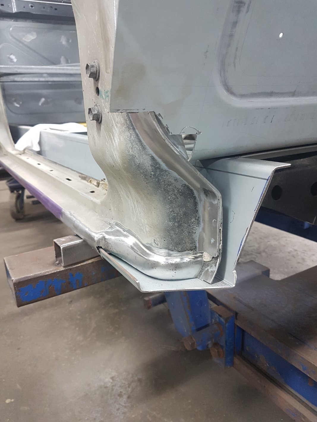
The body drop equates to a 3-1/8" (80mm) drop. Relatively pretty big on a Toyota and cut into the rocker panel Here's the sill panel folded up and construction of the floor structure
7 points
-
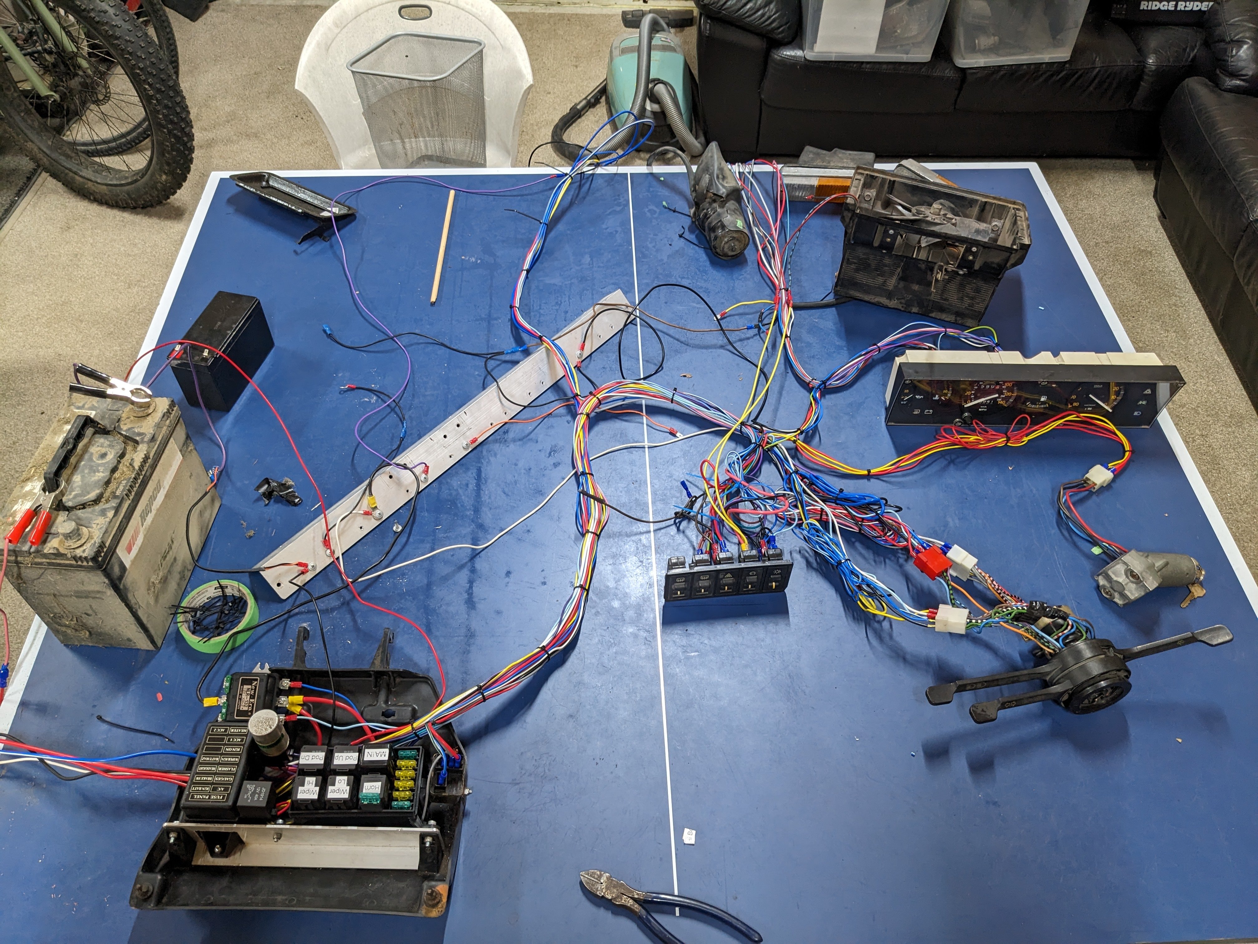
Pretty much done, the Fiat fusebox is mounted on a handy drop down tray, I managed to mount everything on without too much bother. 'Finished' that is apart from the things like the headlamp and pod motor wires that I will run once I have it in the car so I dont waste wire. And the brake circuit. And indicator wires. And the running lights. And all the shit in the engine bay; starter/fuel pump/coil pack/sensors/etc. So probably not all done in the slightest.
7 points
-
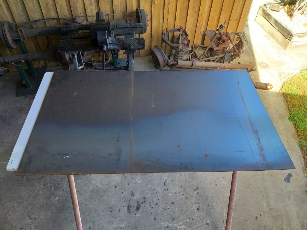
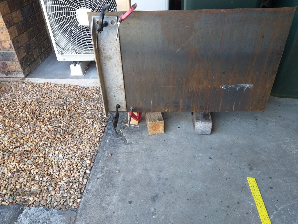
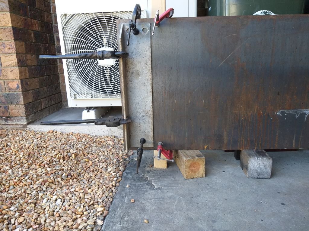
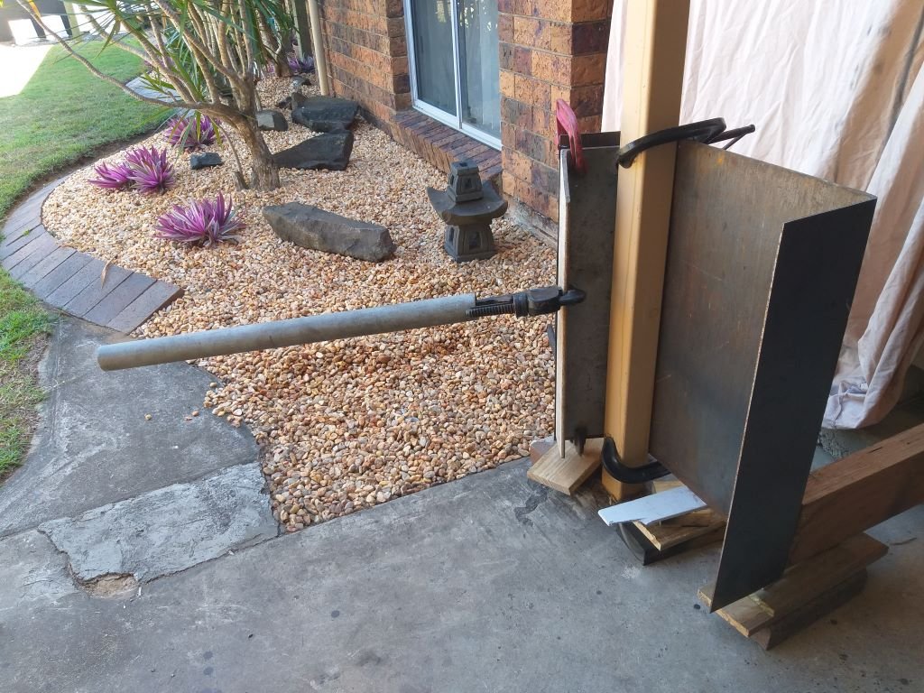
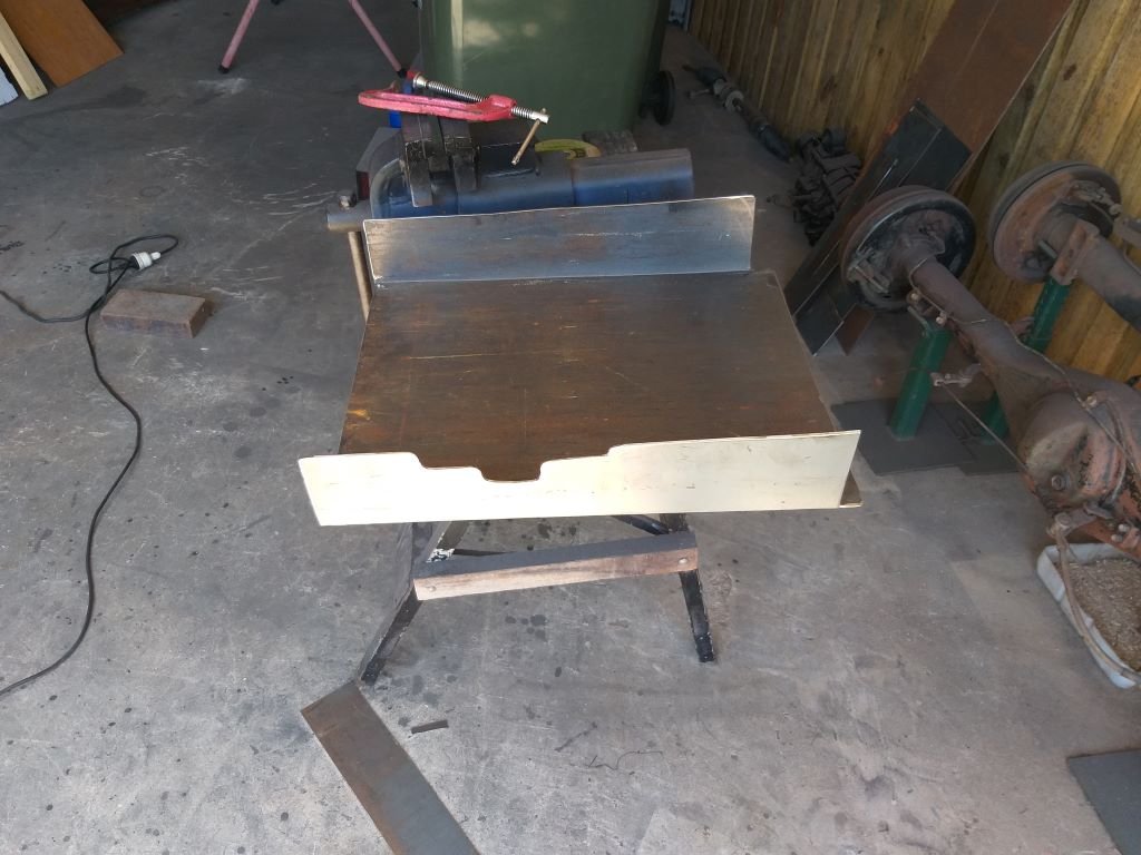
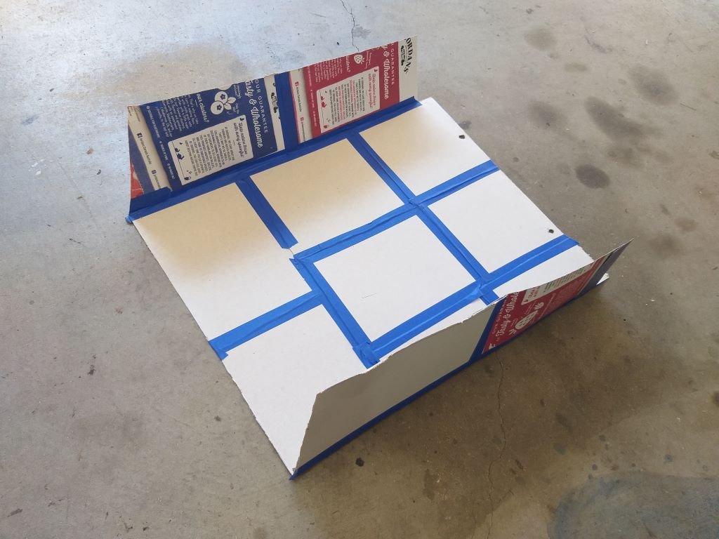
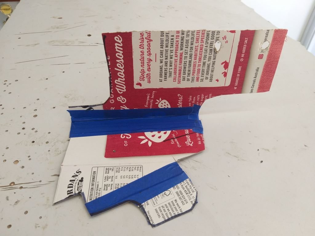
Created a second air deflector mock-up using an old piece of plywood which made it rigid enough to create accurate side profiles in cardboard. The funky shaped cutout on the driver's side upright is needed to clear the floor mounted high beam switch. A test fit proved successful, so I rummaged around in my sheet metal bin, but sadly I didn't have a piece of flat plate big enough, so yesterday we did a trip into town and I picked up this 1.5mm thick beauty: Had to figure out a cunning way to fold up the main shape. After a bit of head scratching, I decided to use one of the steel posts that hold up the roof for our back carport. Gave the plate a bit of a score and then clamped it to the post with an old bit of angle iron attached for leverage. My two big pipe wrenches and a handy piece of thick-walled steel pipe for extra leverage and my bender was ready to go. And then there was this: Gave the sides a bit of a trim and then carved the little notch to clear the high beam switch and she is almost ready for a test fit. Tomorrow I'll poke a few holes for mounting up front and then I need to create some mounting brackets to attach the rear of the duct to the chassis. Thanks for looking.
6 points
-
Fucked up and took Anglia to vtnz for wof, multiple rechecks and brake adjustments later they told me to just go somewhere that does a road test instead of rollers. The car stops dead straight with your hands off the steering wheel but every time they test it the back brakes give a different result. Bugger em, booked in for a wof somewhere else now5 points
-
I am a dumb fuck probably. But it is mostly because it looks like there has been a fairly serious electrical issue or maybe a small fire. The battery tray area has had a lot of metalwork loving and so it is possible the original fusebox just got filled up with rusty water from the battery area, I did have to clean out more grime and shit from that tray than I would have expected when i removed it. Whatever the reason, someone has grafted a new front section of the loom and fusebox onto the old one. I do not have any level of confidence in this work, although I don't really know why or if that is a real issue. Either way if I was to just use it as is then try and troubleshoot any issues I can see unbelievable levels of frustration and anger in the future if shit no longer matches the factory diagrams. Then there are some known X1/9 issues; High amp power going through the key switch, headlamp supply, headlamp pod motor supply etc, all of which should really be going through relays and have bigger supply wires. These well known issues had not been addressed at all during the rewire and if implemented would essentially be a whole lot of dirty hacks grafted in to what is there, making the loom even harder to work with and to understand. Plus everything was unplugged and the car essentially disassembled, TBH the decision to do it made itself. But yea I hear you....4 points
-
I'd just put later 17's on it. It should be possible to get a 4.5in rear on without much trouble, a 5.5 is a bit of a squeeze. The 1135 donk is the king of the early GSX's, stock they are very quick. Judging by the pipe, pods and APE sticker your dad has already had a go at it. Any memory or record of what he'd done to it ? Over the years I've built a few of those engines for road and track. Just ask if you need to know anything.4 points
-
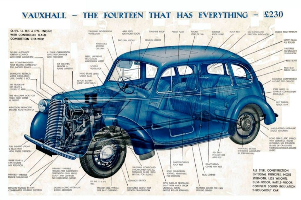
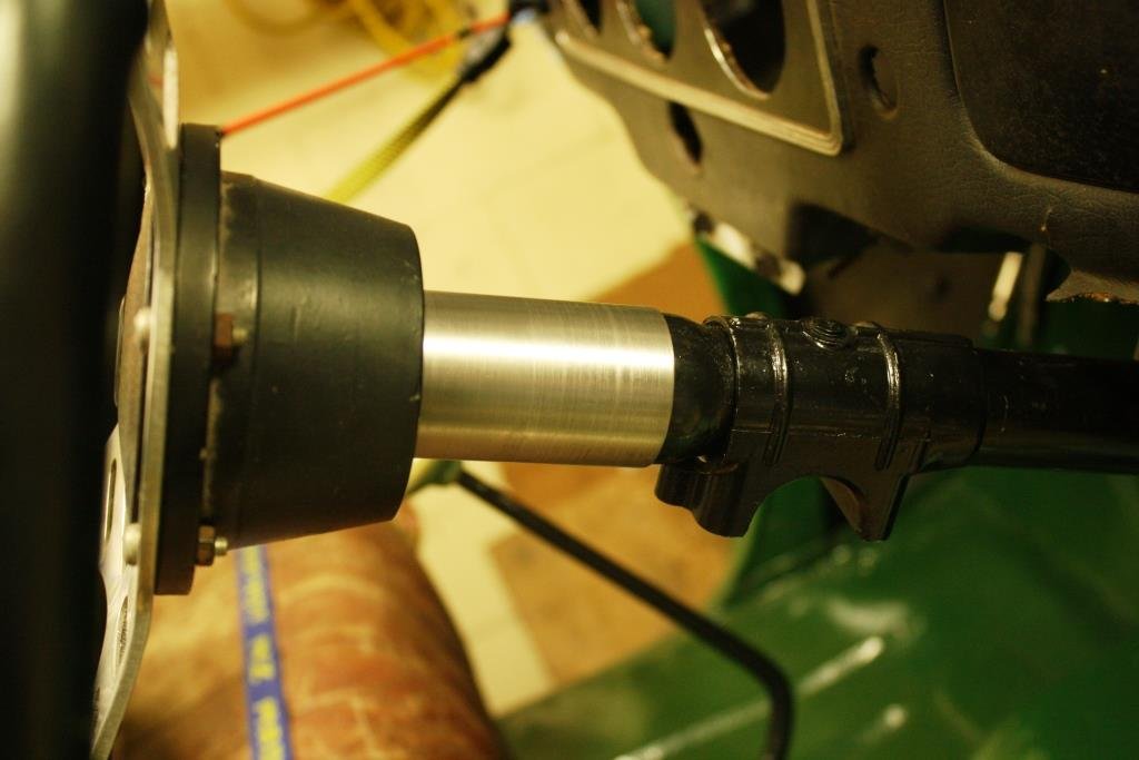
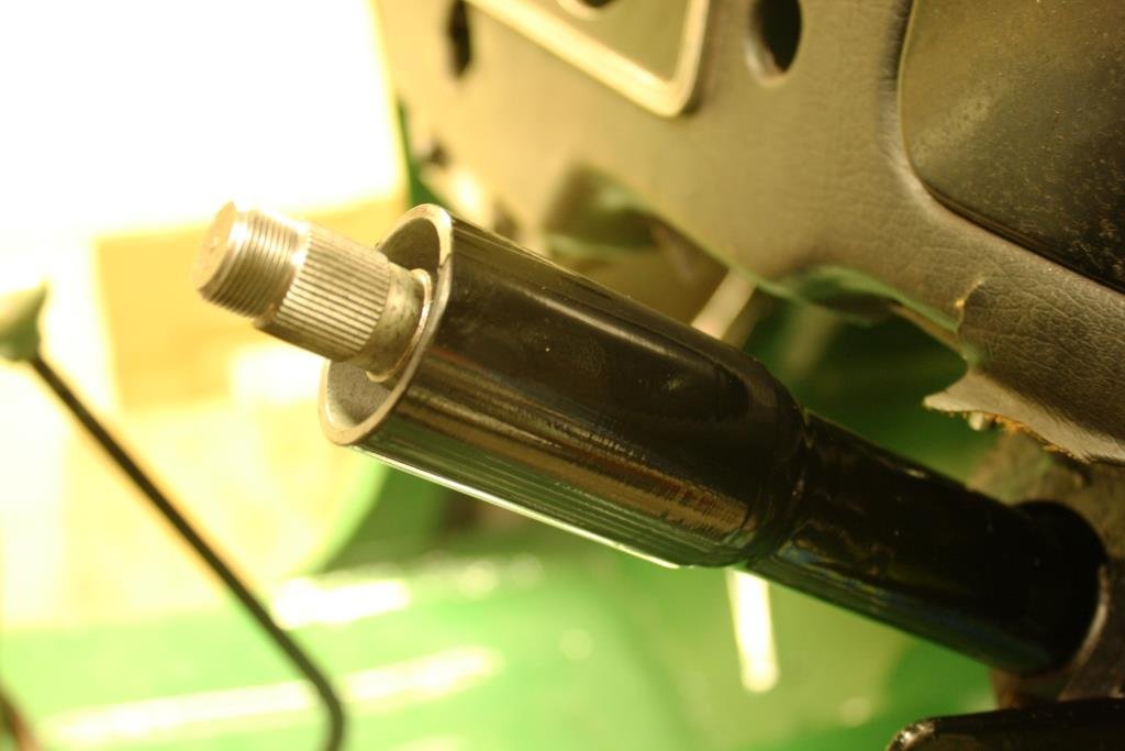
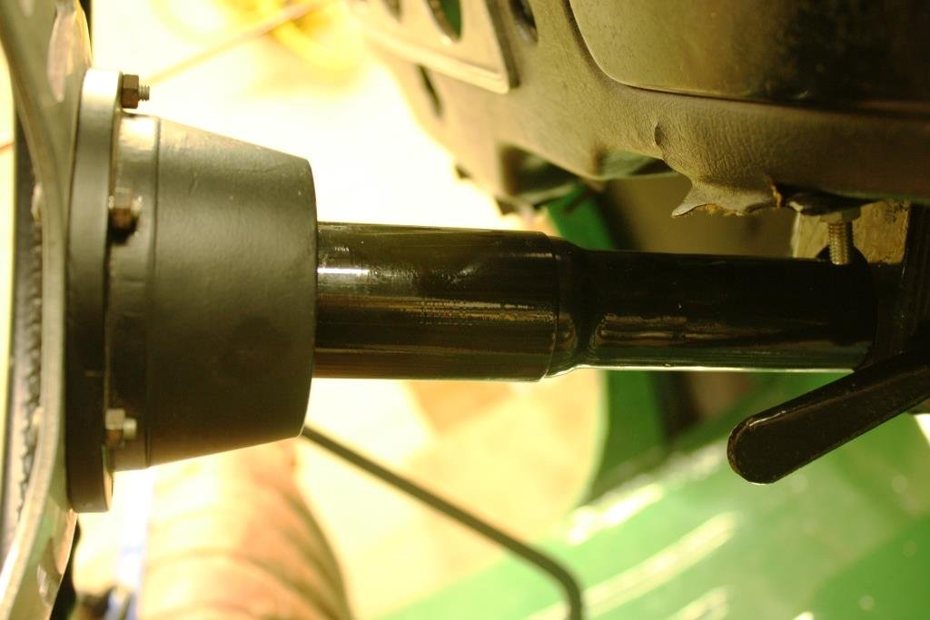
As I mentioned earlier the steering wheel needed to come closer to the dash. Originally the J14 Vauxhall had a solid steel steering shaft that went from the steering wheel to the steering box; essentially you were driving around with a steel lance that went from right up the front of the car to 6 inches away from your chest. The mind boggles at the thought of having an accident in such a setup with no collapsible column, no seatbelts and no crush zones! With the narrowed Austin steering rack mounted behind the HR Holden cross member Rigamortice’s steering column needs two universal joints to get past the engine. This addition of an intermediate shaft at an angle to the main steering column gives some collapsibility in an accident. Combined with seatbelts it’s a big improvement on 1947 safety standards. I’m never going to make Rigamortice as safe as a modern car but I’m still keen on staying alive for as long as possible and am looking forward to living long enough to become an obnoxious, cantankerous & grumpy, dirty old man! Luckily most of the old English mass produced cars used the same splines in their steering systems so it’s easy to mix and match. I managed to source a shorter Triumph steering shaft and I shortened an original tube to fit to give me the desired length. Original and shortened Triumph 2000 steering columns…….. Only problem was this ugly gap between column and steering wheel… Being a tight bastard (short arms & deep pockets) I started with a scrap piece of galv. water pipe. Stuck it in the lathe and poked a boring bar down it…….. Cleaned up the outside…. And ended up with this…. Checked that it was still a good interference fit….. Three coats of black epoxy enamel and it’s a good result.
4 points
-
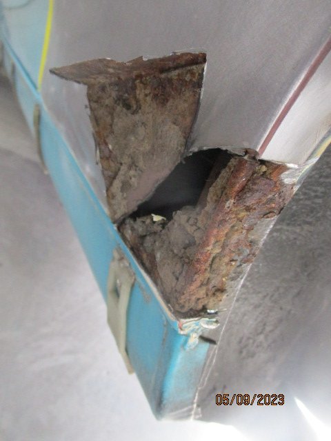
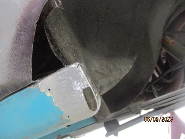
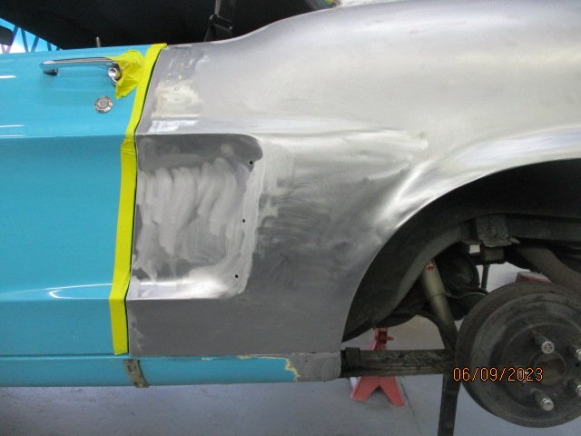
Winter sucks. Not only is it cold and dark, but it also makes working in the garage a somewhat unappealing prospect. That, and having other projects on the go, caused a bit of a slowdown with the Marina. But finally, Lucas is gone, so no more time needed to be spent there, and we're in spring now, so it's getting warmer and lighter. With that in mind, I took some time off work to finally dedicate some time to the Marina, as it's been so good just sitting there waiting, while everything else gets the attention. First though, let's step back in time to June, which was the last time I worked on the Marina. To finish off the door opening area of the sill I used a thin skim of filler just to even out the low spots where the plug welds are, and to tidy up the front edge of the sill where it meets the guard The window opening also got a skim of filler to smooth out the work I had done there. That rear curve was a real pain to do. You may have also spotted in that first photo that the floor pans were also seam-sealed. I did this to both the top, and under the car. It's not the tidiest; it's brush on and the goal was to get a good coating and not worry too much about how it looks since it will be covered by carpet anyway. Once that was done, since I had managed to acquire a new bottle of gas for my welder, I got stuck into the rear valance again. As some context, I started this valance way back in January. To get to the valance I first had to remove the tow bar. I don't really want this car to be towing anything, so it's unlikely this will go back on again. I'd previously removed the wiring and holes for that, too. It looks like Old Mate took a few tries drilling the holes before getting it right... But it came off after a bit of a fight This gave me clear access to the valance. A quick whip over with the strippy wheel, and this is what I had. Damn. It's pretty well contained to the LH side though Amongst the rust there are also some old holes for what I presume were a different screw pattern number plate. They will get filled too. I started cutting And found a couple of spots where the inner panel was rusted through too, so out that came To be replaced with a couple of bits of nice fresh new metal, all folded up to suit With the inner ground back, The first section of the outer went in. This little filler section was mainly to keep the upper section and lower lip in place so I didn't lose the profile. The real patching started with this random little hole off to the side Which extended into filling the rest of the gaping hole with new metal It's not the prettiest, and to be honest the primer makes it look worse than it is, but its nothing a skim of bog won't tidy up later And that's about where I ran out of welding gas. So, six months later, more gas in hand, I got back into it. With a fresh new perspective, I cut the rest of the lower lip off (it wasn't going to survive) and a new lower section was welded in place. This was also plug welded to the inner section I had previously replaced. A couple of smaller holes on the RH side got the filling treatment I folded this section up, stuck it in place with some magnets And metal glued in I cut out and welded up the other smaller patches, and once it was ground back a coat of epoxy primer protected it I would've loved to have a new valance panel like the Brits have, but the shipping cost would be prohibitive, and they just aren't available here. Instead, we'll make do with what we have. And that brings us up to date. Three months later, here we are. The first job of the day for yesterday was to cut the rear quarter panel up again, as I just wasn't happy with it. When I originally welded the new section in, I didn't leave enough of a gap, and when I welded it it resulted in a pointed high spot where the two panels met. I tried to hammer it out, and made it better, but just moved that metal to somewhere else in the panel. I also wasn't happy with the gap between one small section of the quarter, and where it met the sill. The gap was larger than the rest of the panel. I tried to fix this with filler, but I wasn't happy. So I cut it. I cut the bottom section out to fix the gap, and the big vertical cut released a lot of tension in the panel, allowing me to hammer it back into alignment. Opening this up also allowed me to tweak the arch section of the panel, which always sat slightly recessed from the sill. Once it was all welded back in, it was much better. Theres still a lot of finishing work to be done, but I wont be contending with a massive high peak in the middle and a deep low at the end I also completely finished the sill. There were some plug welds missing from the end, and I had to make and weld in a plate on the back of the sill to join it to the inner sill. I seam sealed the gap, which in hindsight I shouldn't have done until after using filler, but oh well With that done, the next goal was to finally refit the passengers door. It has been off the car since December last year. It's almost a car again The panel gap between the door and the new sill isn't perfect, It's a little tight at the front of the door, but it's not touching, so it's good enough. The door does need to come back a bit, but it's maxed out on its adjustment. Looking at photos, it's always been like that, so I'll need to shim the hinges, or slot the mounting holes a bit. That's a job for another time. It does open and close lovely though, even with a test door seal in place. The final task for the day was to give all the areas I had welded and seam-sealed a top coat of enamel paint. The floors were coated top and bottom Yes, I would have rather had satin or matte, but they only had gloss. The carpet will cover it, and the underside will be undersealed anyway. I also did the little strengthening ribs in the rear too, since this is where any water is likely to pool if it did get in. The rear inner boot pocket I fixed got coated too. This will likely get over-coated in yellow at some point With one full day's work under my belt, I went into day two with a list of things I wanted to try to get done. The first was to cut out and fix the seal lip on the boot opening. Most of this came off with the seal when I removed it. I had been putting this job off as it looked complex, but it ended up being a lot easier than expected, just really time consuming. I started by cutting out a small section and welding a patch in, just as a proof of concept, but it worked well, so off we went I worked my way along, using scraps from the work bench. Measure the scrap against the body, cut the rust out, clean up and weld in. And keep moving, patch by patch I left the scrap bigger than I needed, so I could trim it size afterwards There was one small spot where the actual vertical panel had a pinhole in it, so that was carefully cut out and a patch welded in there too This corner section was interesting. I hand-shaped the replacement section until it perfectly matched the profile of the original, and then cut and welded it in. The final section was welded in. Many hours later. Yeah, there are still a couple of frilly areas, but it's all under the seal and they were pretty solid otherwise, so I'm not worried. After some touching up with the grinder, it all got a coat of epoxy primer After spending so much time fixing that, I moved on to one of the other jobs I hate, filler. The valance didn't need too much, but the quarter is a bit wobbly and might need a couple of goes. I'll sand it back tomorrow and see how good I can get it. It's not something I look forward to. This has been a huge boost towards having the car on the road again. Other than some cosmetic work, like fixing the dent/rust in the boot lid, and fixing the heater box, this signals a huge milestone; all the welding is done.3 points
-
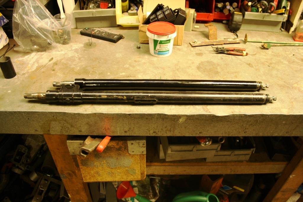
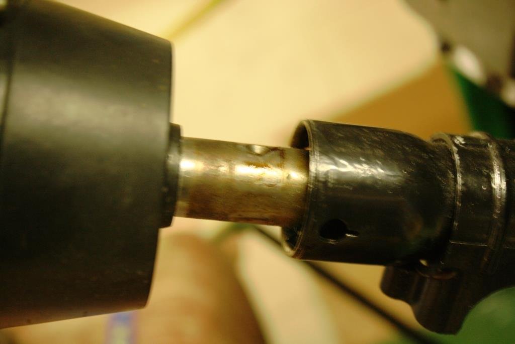
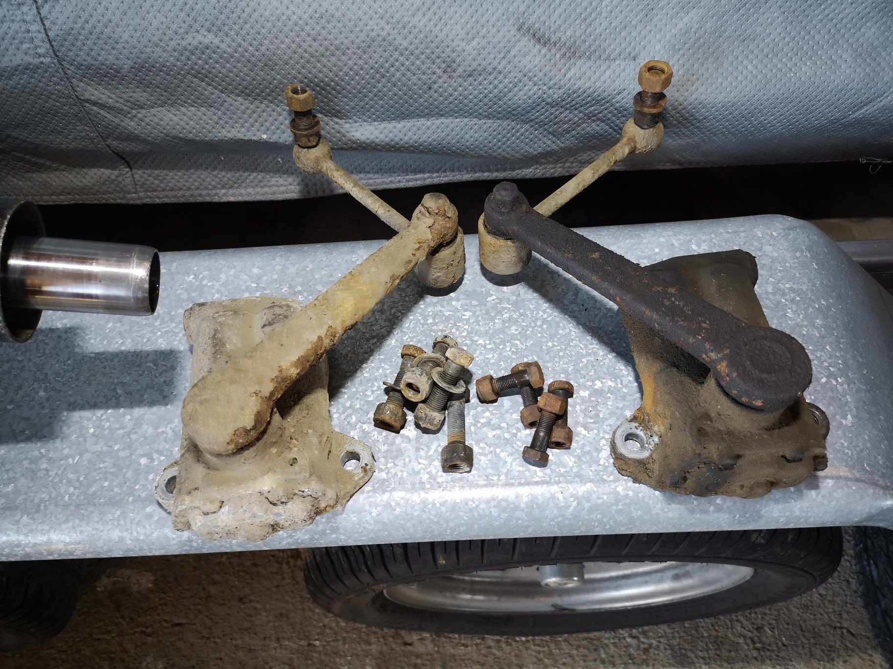
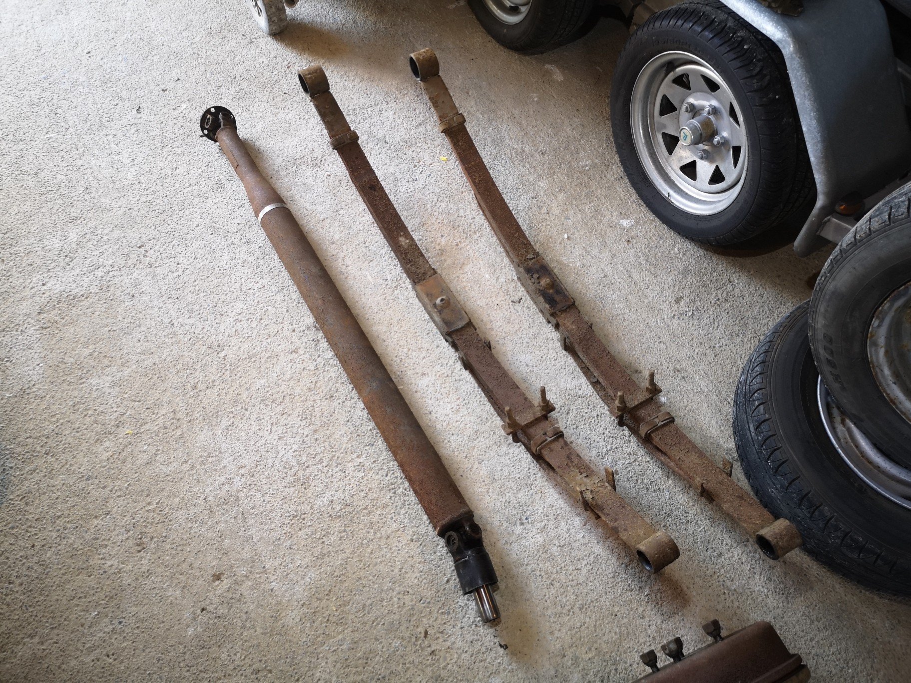
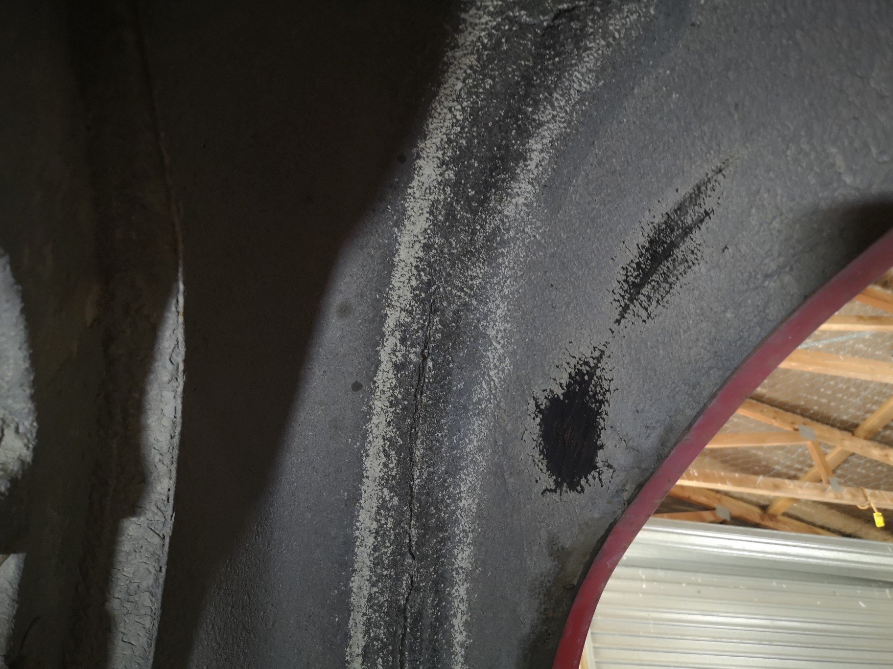
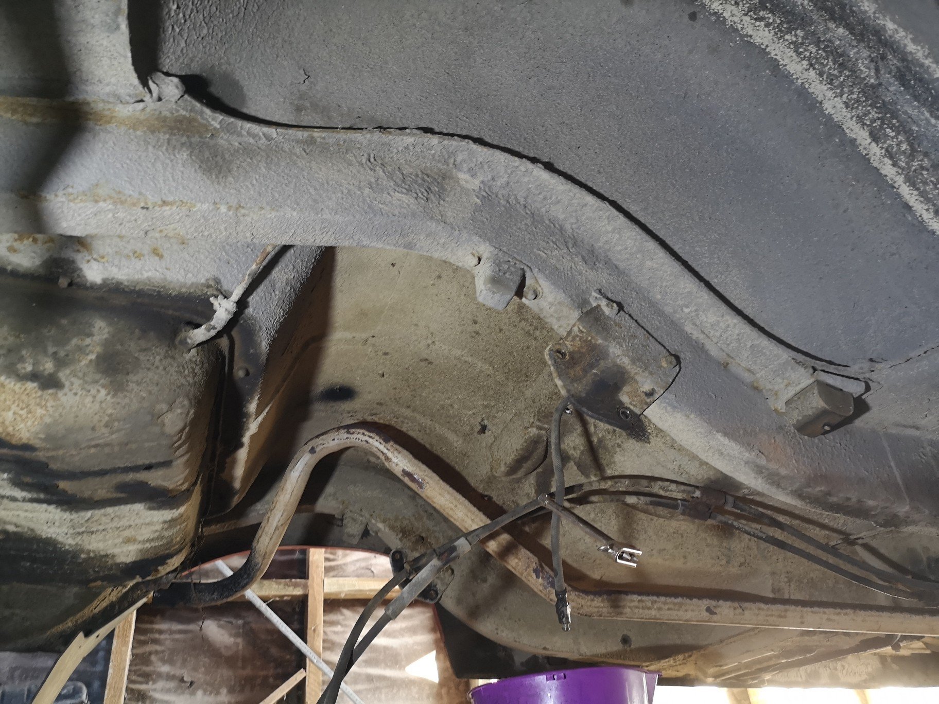
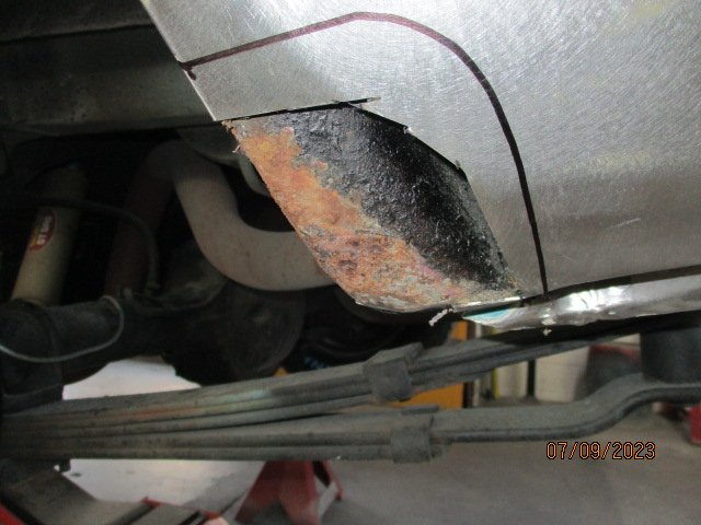
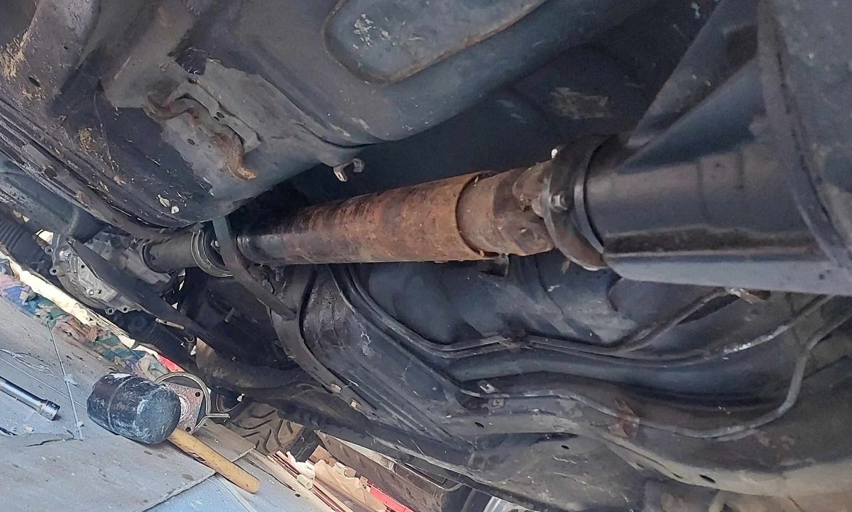
There are numerous topics on converting from lever arm socks to telescopic and even a guy on trademe that sells a bolt on kit (it looks very weak with the bottom shock mount hanging off the leaf spring plate) but I think I'll just recon these and see if I can in some way make them offer a little more resistance. I'll get this driveshaft balanced as the other one I had was apparently permanently out of alignment. Hopefully this one will be better. It was also fairly soft in the back which made for a nice ride but if there was a couple of people in the back it dropped quite significantly, will talk to a mate of mine in chch who is a major zephyr Barry and see what I can do spring wise. All in all its good enough to leave under there, a couple of bits of very light surface rust that I'll treat with Lanolin, and clearly the exhaust has seen better days. There is also a fairly large amount of side to side movement in the diff and the bushes feel fairly soft, would like to upgrade to a harder compound rubber in the bushes as opposed to urethane although apparently superpro bushes are a lot better quality than nolathane. (any experiences?) you can also see below where the 16s I had the center moved on have been rubbing against the inner gaurd might just leave them off for the wof but I think it has lots to do with the lateral movement.. I will also be lowering her finally @Valiant..
3 points
-
It’s just much tidy, less clean up. I’m also more confident in doing a nice Tig weld over a mig weld. The Tig welder is also better than the mig at home. Basically just use the mig for plug welding and feeding me thin mild steel filler rods to Tig with haha2 points
-
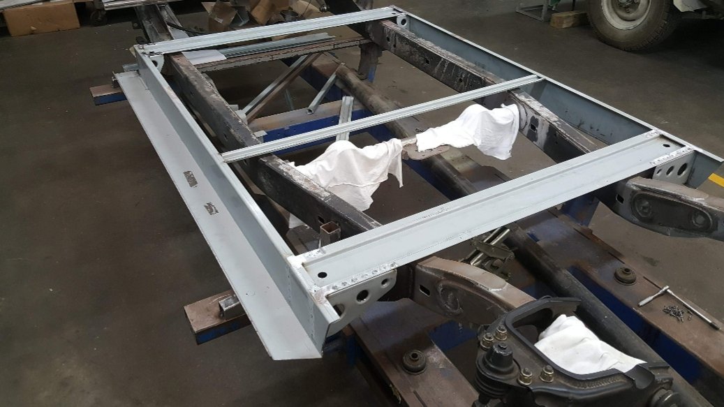
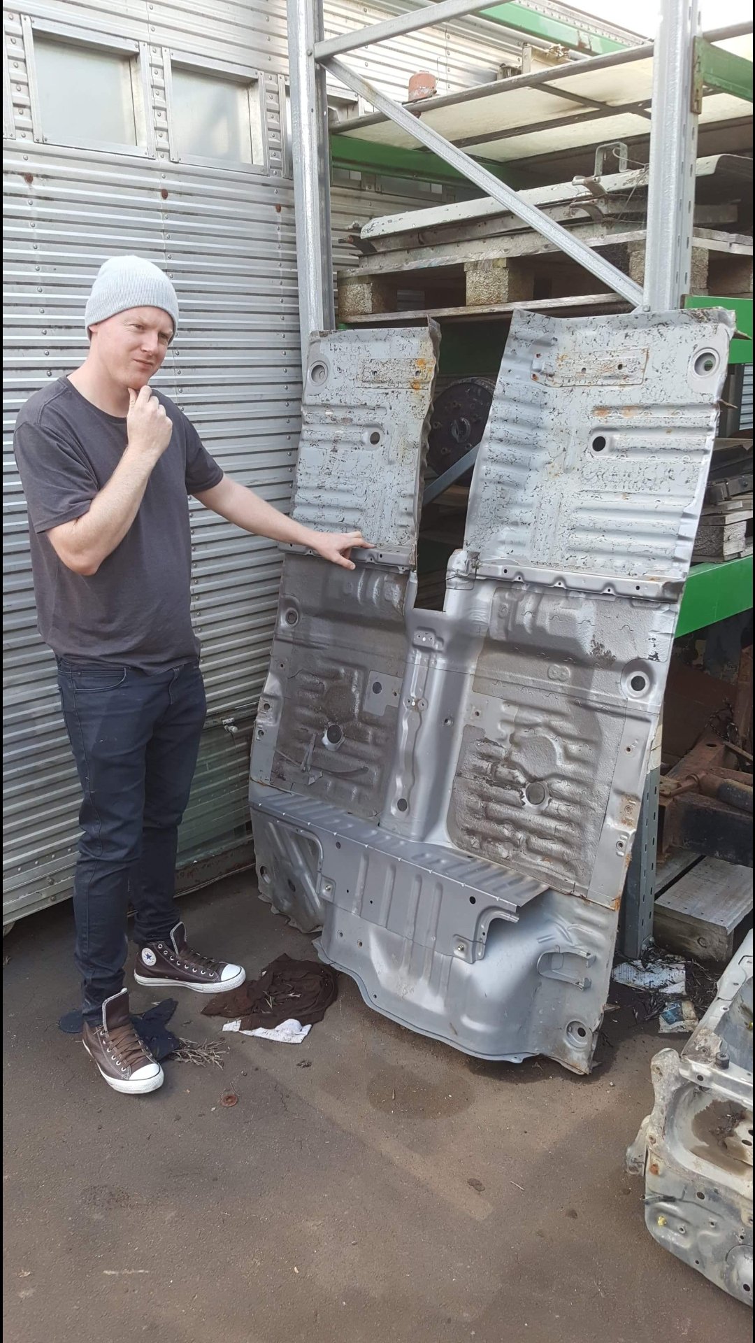
Upon a previous visit to see Matt I was pleasantly surprised to see my factory floor in the scrap pile, as you'll note the tunnel was removed, but it just wasn't going to work, so the decision was made to go with a full scratch built floor, front and rear firewalls. It didn't exactly pan out to this extent, but I have the confidence in Matt to build my dream, and he knew I would appreciate his vision so I'm glad he made the call. I'm now committed to go all out on this thing and to see it through
2 points
-
Don't want to rain on anyone's parade - but an original or close to original one is highly collectible. Please don't do anything irreversible. Story for context. My old business partner raced big Suzukis back in the day. The year that the NZGP was held on the Sydenham street circuit he was running the same model as you have in F1 and senior Production. On the second row for the F1 GP, got a good start - 3rd into turn 1 (as verified by the photo he had on his wall) Then the gear linkage fell apart leaving him in 2nd gear. Rest of the race in 2nd gear and still finished fourth.2 points
-
Cheers dude. I should really just get some tires, rebuild the carbs and go over the brakes and just ride it for a bit. Ive got a bit of a pay day coming up and it's easier to spend money on a bike that I've already got to get it going than buy another complete bike. Be nice to ride it this summer if we have one.2 points
-
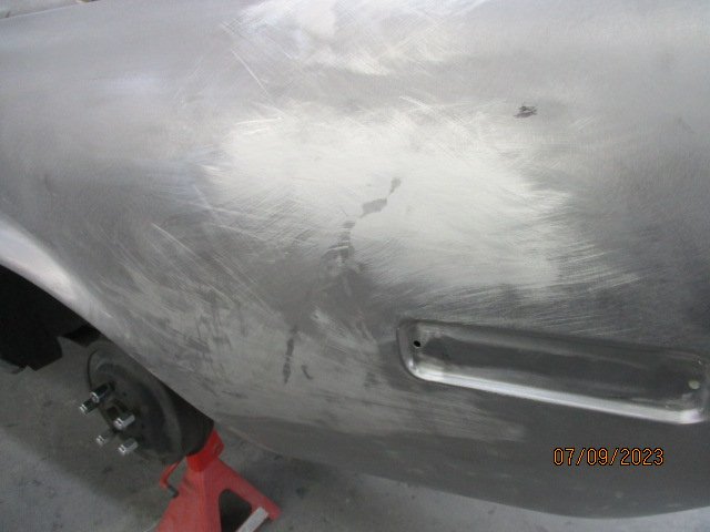
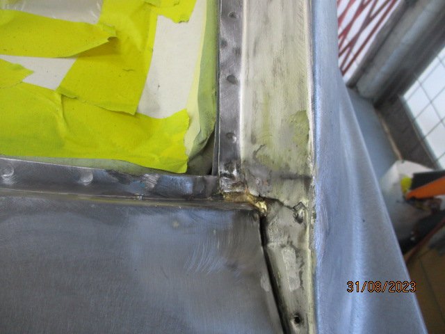
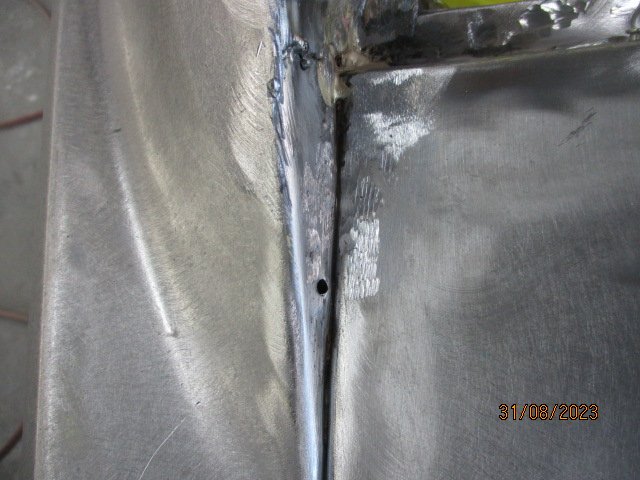
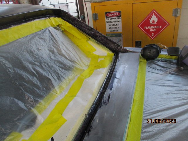
More repair photos from the tin basher No more crud or 'bullet holes in the side panel. Welded up the extra trim mounting holes as well. Same at the back Rear window crud removed And treated I'm guessing it will be ready sometime next week, then I'll have to pay the bill.
2 points
-
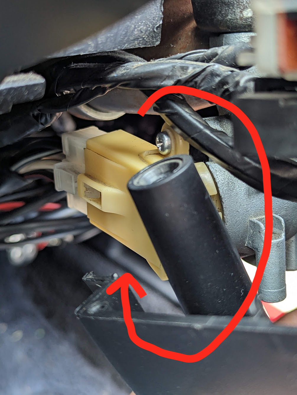
Dunno really where else to put this, but it might save someone's day who has been putting some work into their google-fu. We were suffering a no-start no-crank issue with our MX5 NA and it was driving us a bit nuts. Every so often it would fail to start when the key was turned, but backing it off a bit and trying again would usually sort it. The ignition switch is a common failure point on these cars so Girlface serviced it, but shortly thereafter it wouldn't start at all. Sometimes, but not always, we'd hear one-off clicks from the engine bay, like relays being activated. The usual suspects had alibis: Battery is fine (and jump-starting does nothing) Starter is fine (verified by jumping it directly) Fuses all fine Ground lead and positive lead to starter are fine (jumped engine block to chassis, and starter to +ve) It was really starting to get Girlface down and she hates electrical stuff so I rolled my sleeves up and took the ignition switch out, started identifying what pins are active when the key is turned, the idea being I'd jump the loom directly to rule out the ignition switch. However I plugged the switch directly back into the loom when i was done and turned it with a screwdriver... and it turned over no problem! I held it back up to the key barrel, turned the key... no start. It seemed as if the key didn't have enough travel to be able to properly turn the ignition switch all the way. I had a brainwave and rotated the switch as much as I could towards me, there's a fractional amount of play in it, and suddenly the key works every time! What I believe has happened is that the wear and tear on the switch has given it more and more slop over time, to the point where the key at max throw would barely activate it. Backing the key off and trying again might be enough to counteract some of that wear and be just enough to make contact. When Girlface reinstalled the switch she must have given it a little more slop than it had, leading it to finally lose the war to the key. Rotating the switch helps counteract that wear and tear. I also secured it as firmly as I could dare to help prevent it from slipping. Over time we might be able to further extend the life of it by fettling bits of the switch housing such that it can rotate even more. A brand new OEM ignition switch is $225 and 2 months away but we might just order it anyway for preventative maintenance. Hopefully this saves some other poor soul that has tried everything short of replacing the ignition switch.
2 points
-
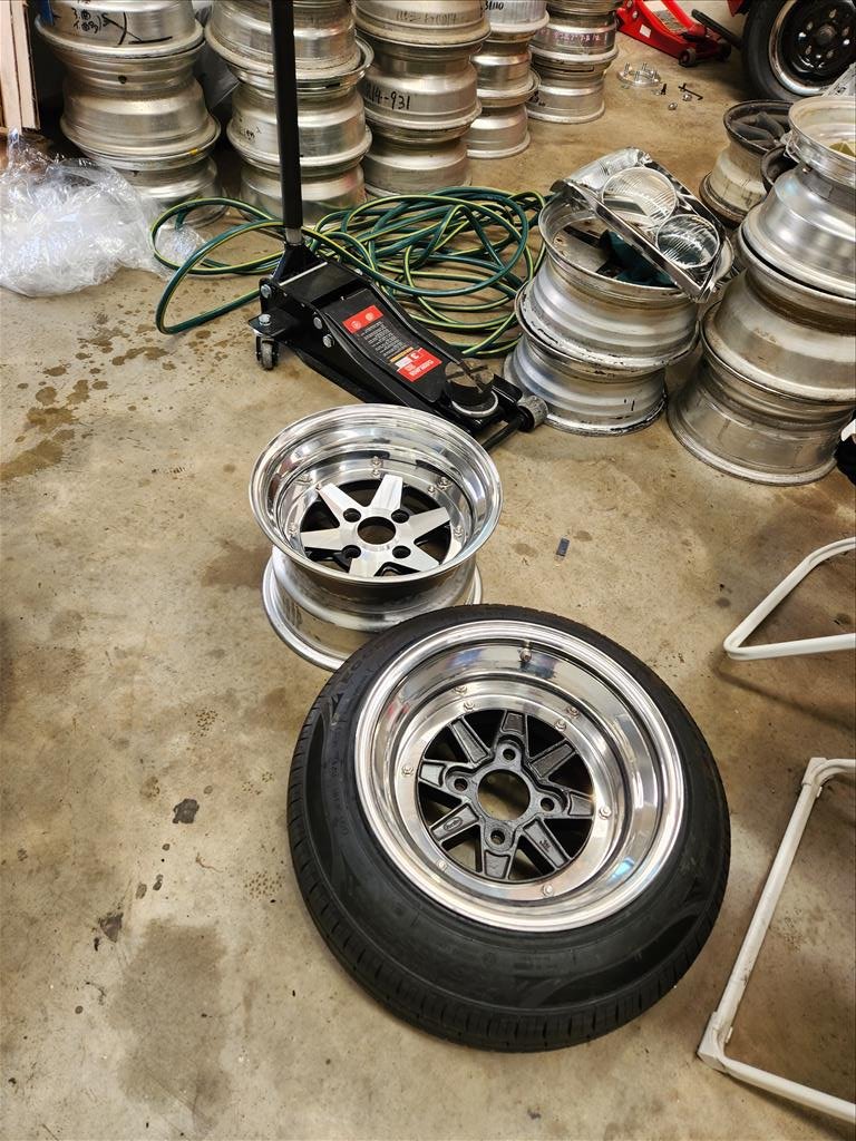
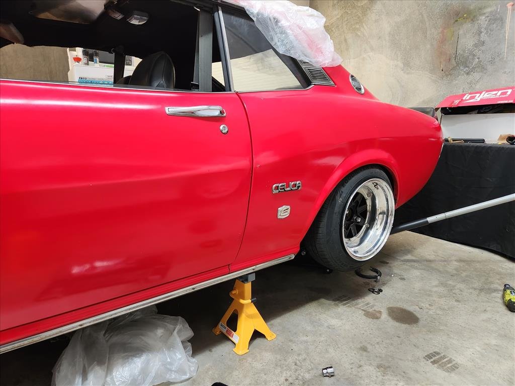
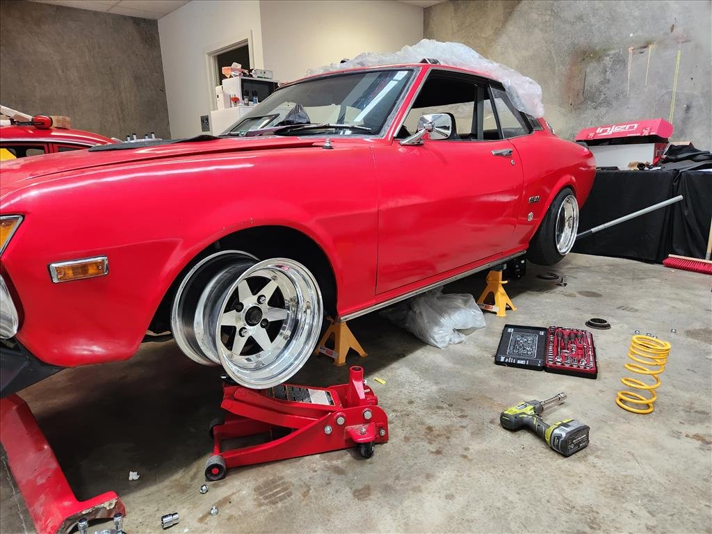
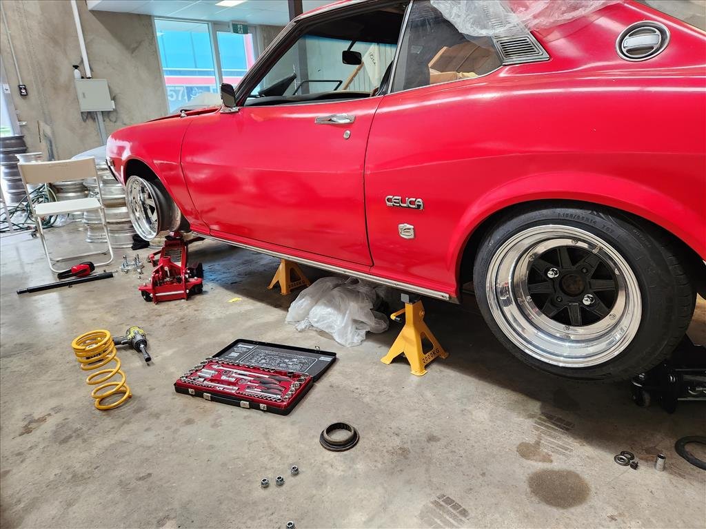
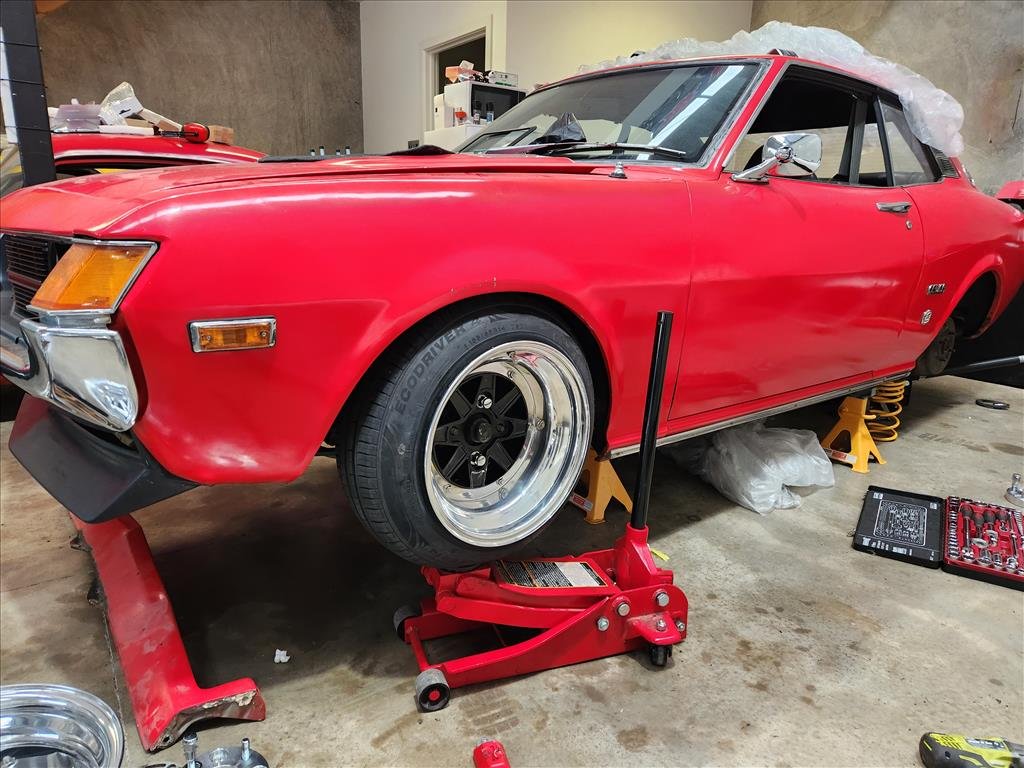
Back from WTAC and my wheel guy has completed the SSR MK3 wheels I gave him to put together a little while back. They ended up being 14x9 -22 and 14x9.5 -28 (approx). They're pretty crazy but also it's a problem and apparently I can't measure properly because the 9.5s will no way fit on OEM body. Because I'm kind of indecisive and trying to put a 155/65 on a 9.5 isn't working very well I asked to borrow a longchamp that he's just rebuilt in 14x9 -15 spec to have a measure up too. Might have to buy them, damn. Anyway, some photos of various fit testing with the 14x9 front and rear. I removed the springs in rear and disconnected shock so it's basically on bumps at that height, looks sick. But I think maybe a slightly less chunky tyre might be the go. Perhaps a 165 55 or something, not sure 100% on the sizes of tyres which are available so a bit more research required. Oddly the longchamps fitted better on the rear and the MK3 better on the front? Probably our measurements are off. I am definitely loving the longchamps..
2 points
-
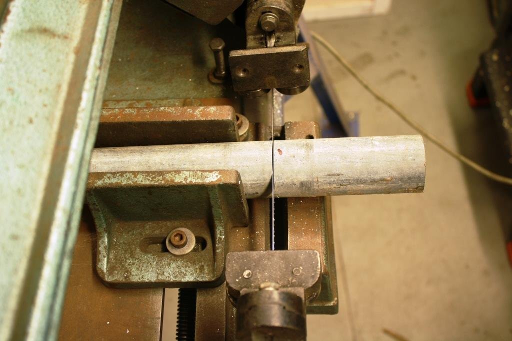
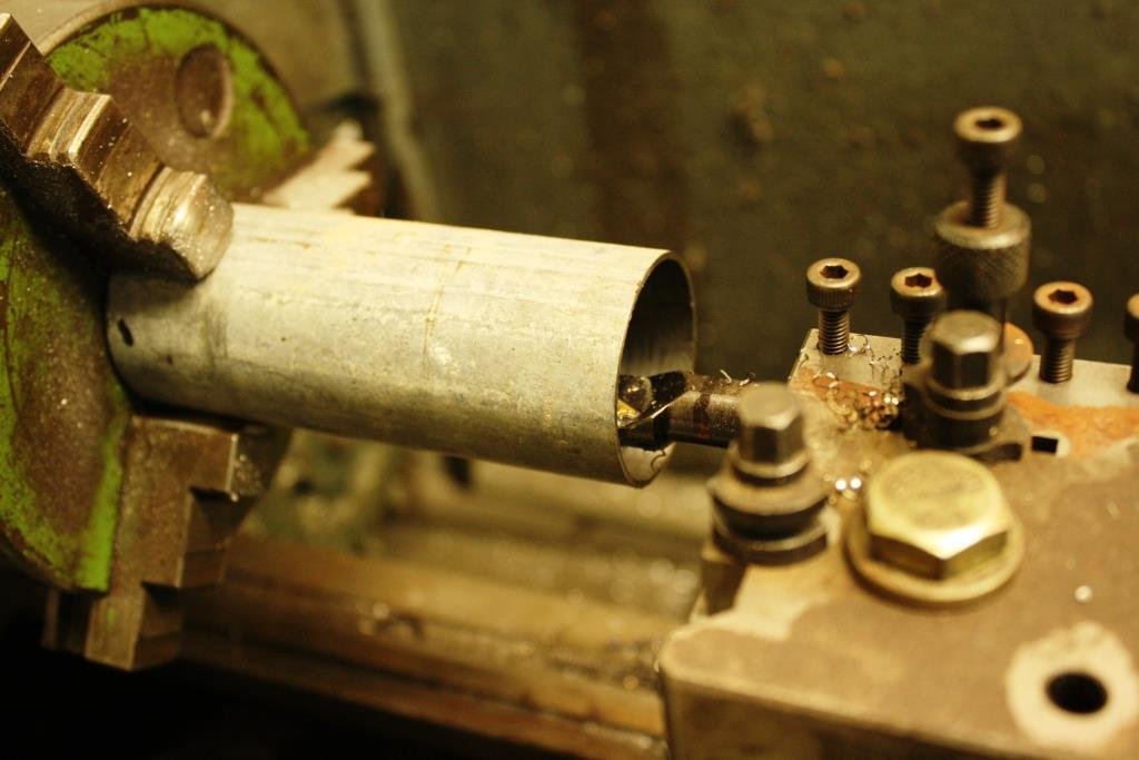
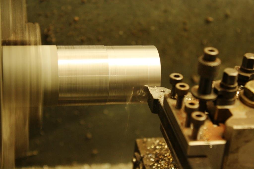
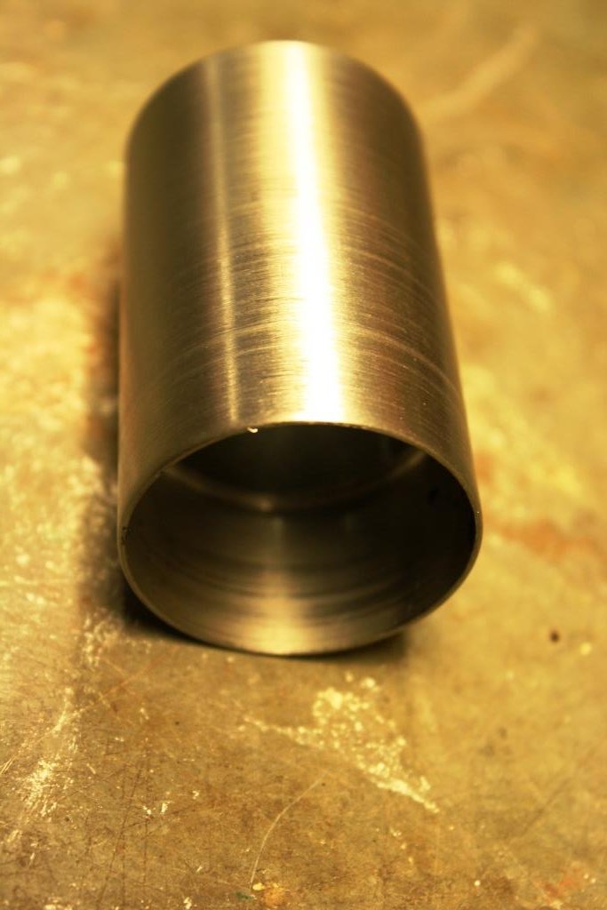
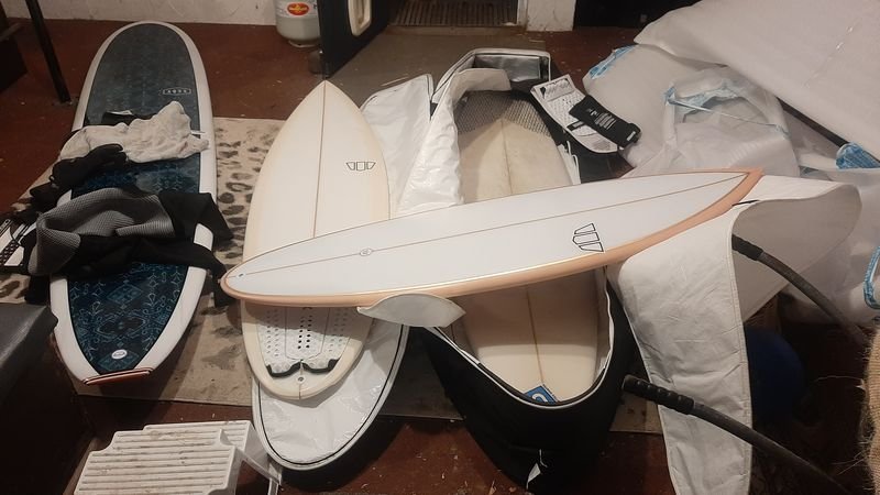
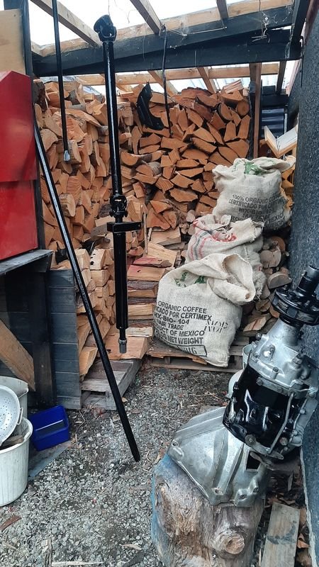
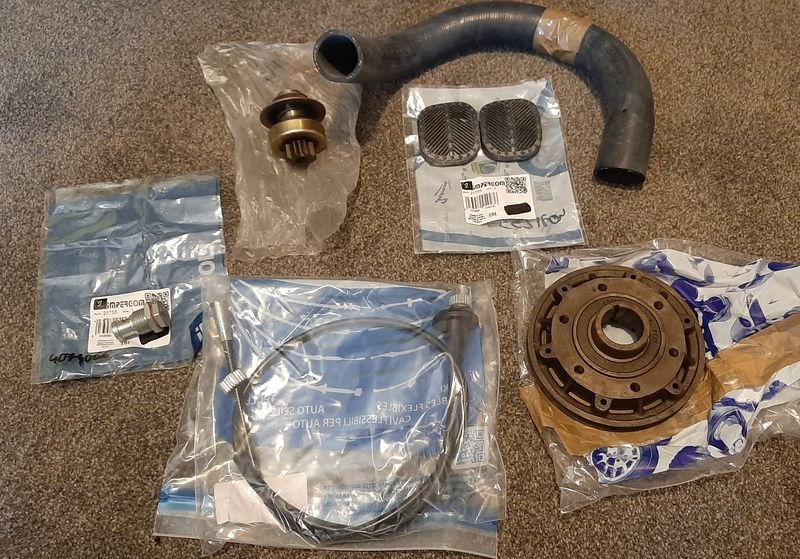
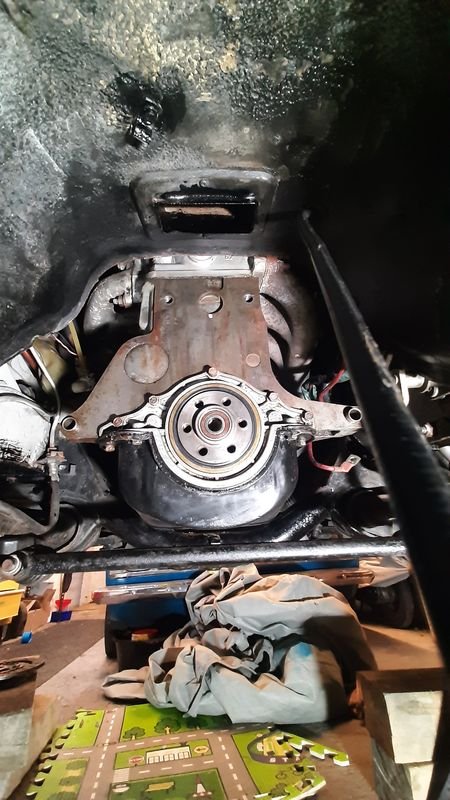
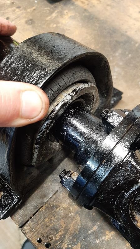
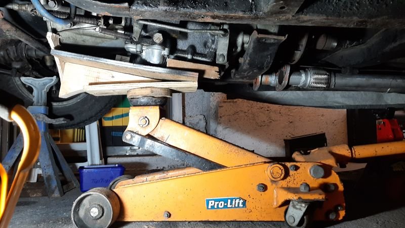
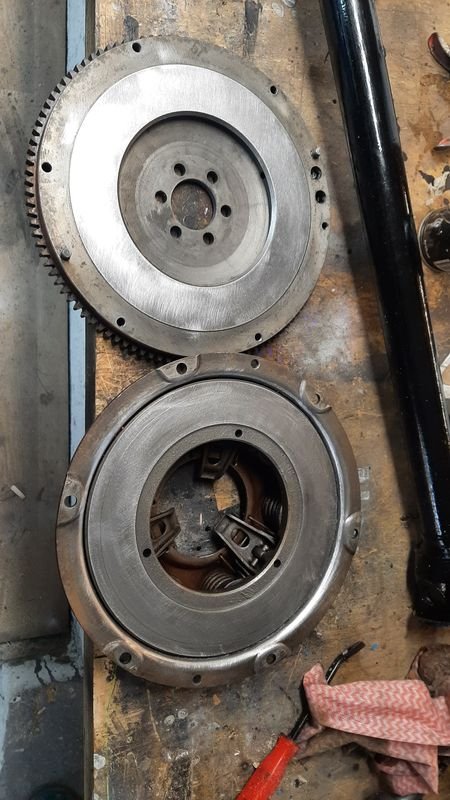
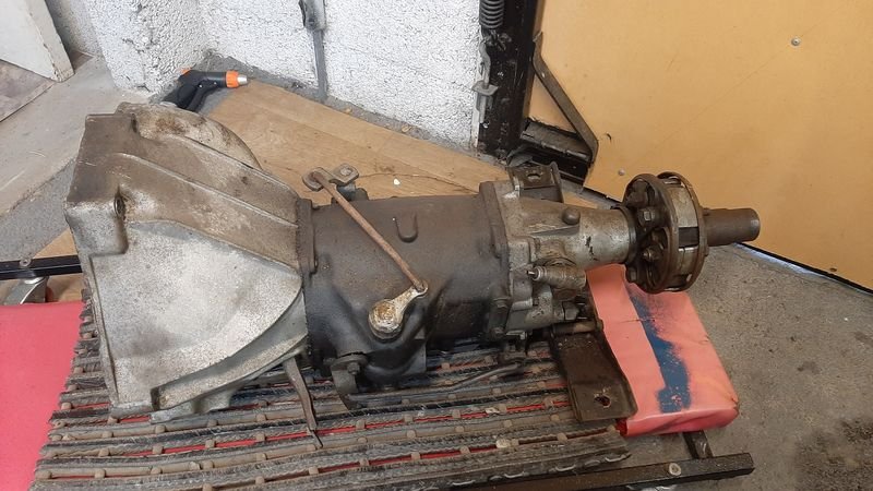
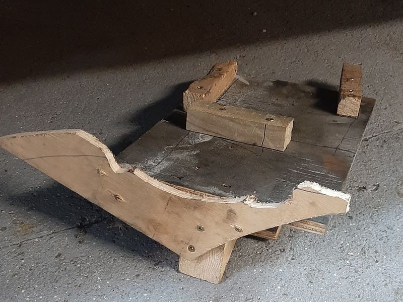
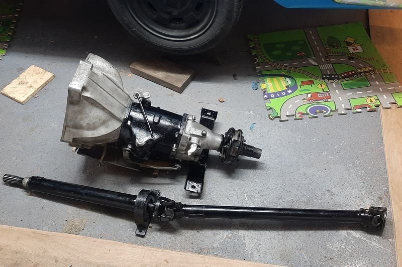
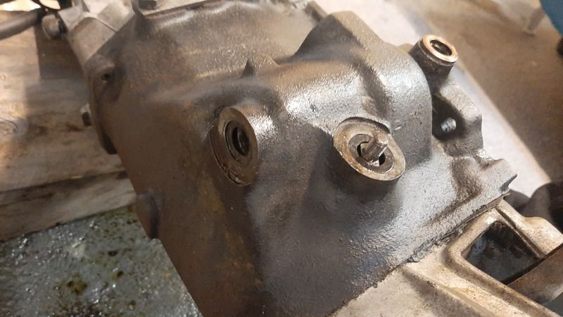
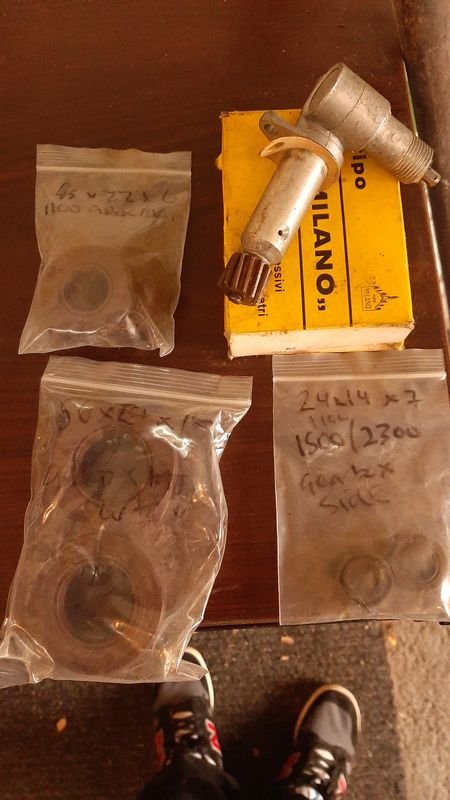
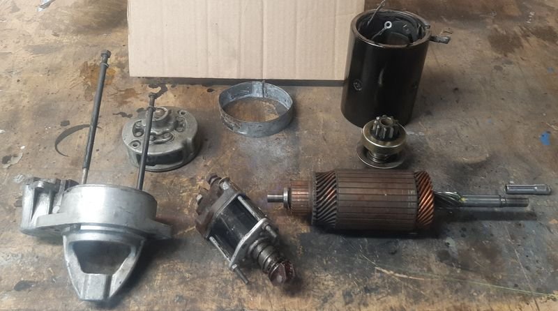
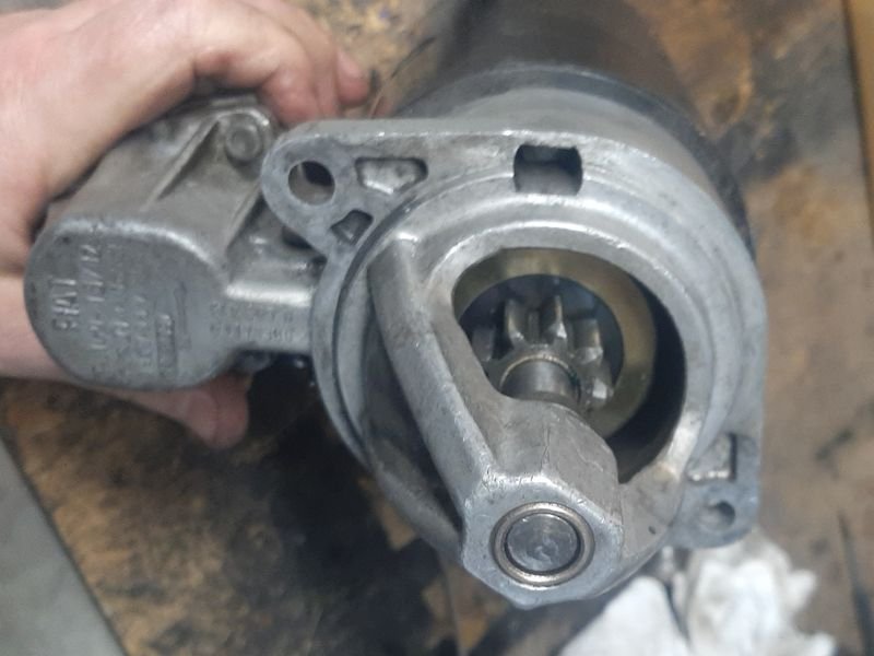
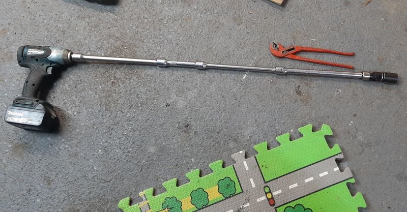
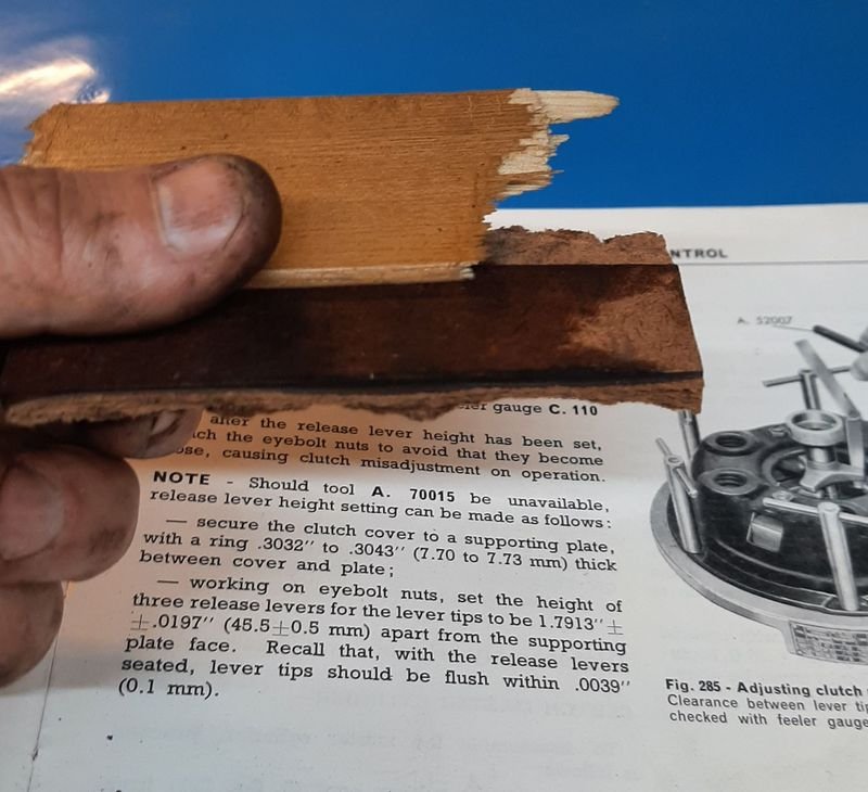
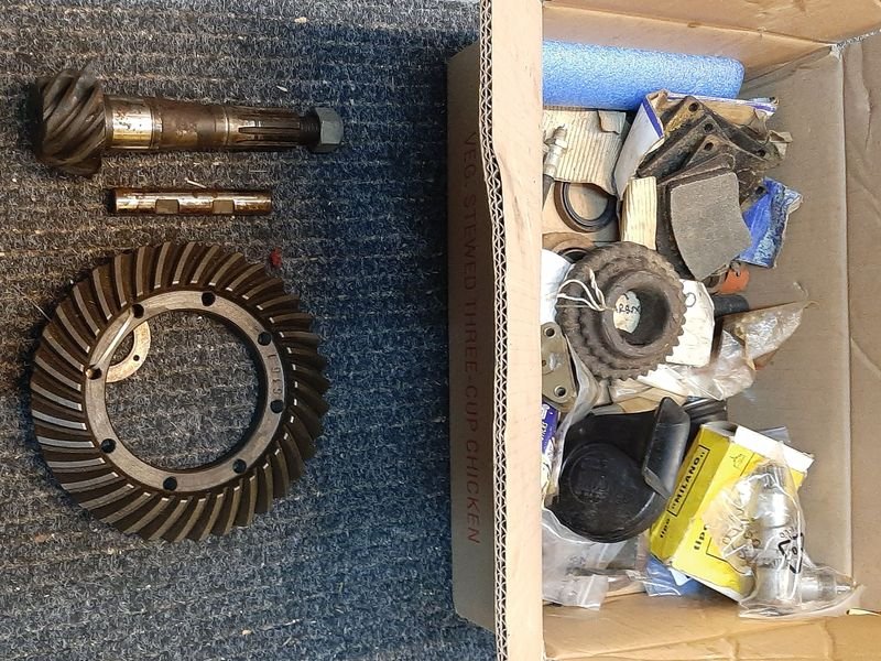
Had to go to Auckland for werk, and came back with a LOT of excess baggage My buddy sent me up with a coffin bag to get 'a couple of boards' ended up being 3 Surfboards (collected from GHS in Muriwai as a favour for my other Muriwai pal who lives down here too - a new 5'0" custom for his daughter and a couple of stockers for him), plus a new 9'2" Mal turned up for me in the post And some gluten free fake meat from Blissful Foods on Mt Albert Rd - nomnom And managed to get out to the lockup to dig though the treasure and filled my luggage with about 20kg of Car parts, including a box of 2300 treasure that id left behind last time such as a spare diff head, some starter parts and a speedo drive I also made an online order, including a starter pinion, pedal rubbers, a special 2300 only crank pulley, speedo cable and an oil pressure valve (for teh 1100T Van) Next job on the list was really a bunch of 'while im in there' tasks all requiring the gearbox to come out - gearbox leak(s) - gear linkages had got noticeably worse over nats trip, to the extent i was having trouble getting into first - get speedo going (speedodrive in gbox is busted) - clutch is a bit shuddery - centre bearing on driveshaft seemed loose So, gearbox out, first, woodwork. Bit easier than bench pressing it, and less likley to drop this cast iron deadweight right on its aluminium pan Lump out Gear box seals in stock The front and rear seals were not leaking but the linkage seals sure were, 24x14x7 btw Rear main nice and clean too, suspect a drip on the rear pan gasket tho. Flywheel clutch and pressure plate all good. One of the clutch fingers was a bit higher than the other two so i adjusted that back down to match the majority. Hopefully that's the slightly juddery clutch bite issue. More woodwork - these wood scraps ended up being ~7.5mm which was good enough to make the alternative to Special Tool A.70015, which was unfortunately unavailable. Pulled starter apart to replace the pinion drive which was running on - an issue since i originally got this going All nice and clean with new paint, new bearing and new pinion Centre bearing. Was new ~5 years ago. The bearing is still fine, and the manual suggests the rubber is supposed to be a fairly loose fit. Nevertheless it got the Sika Flex treatment whcih will hopefully protect the rubber and stiffen it up as well Bits and pieces get 2k black with a brush. Should last better than any single stage or spraycans all of which which ive used before and decided all are a total waste of time under a car imo. All ready for reinstallation, cant see but the centre bearing hanger is all sika'd up, and there is some 4mm rubber strips under the small void that is supposed to be between the gbox mount and the xmember - mount was was soft from the gbox oil leak, should lift it a few mm back to 'as new' Hight and support/stiffen the mount back up and stop it from rubbing on the crossmember. And then installation is reverse of removal as they say. upper bell housing bolt special tool with all the extensions Spent the weekend getting it all back in and adjusting stuff, including replacing a few linkage bushes and clips to tighten that up as well, and got it started up just before, and ran it though the gears on the stand. Speedo works for the first time ever! Linkage is much better! Clutch works! Starter sounds great! Exhaust doesn't leak or rattle! feels good man!
2 points
-
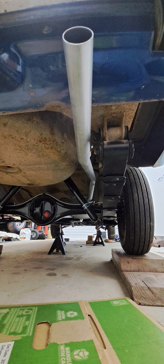
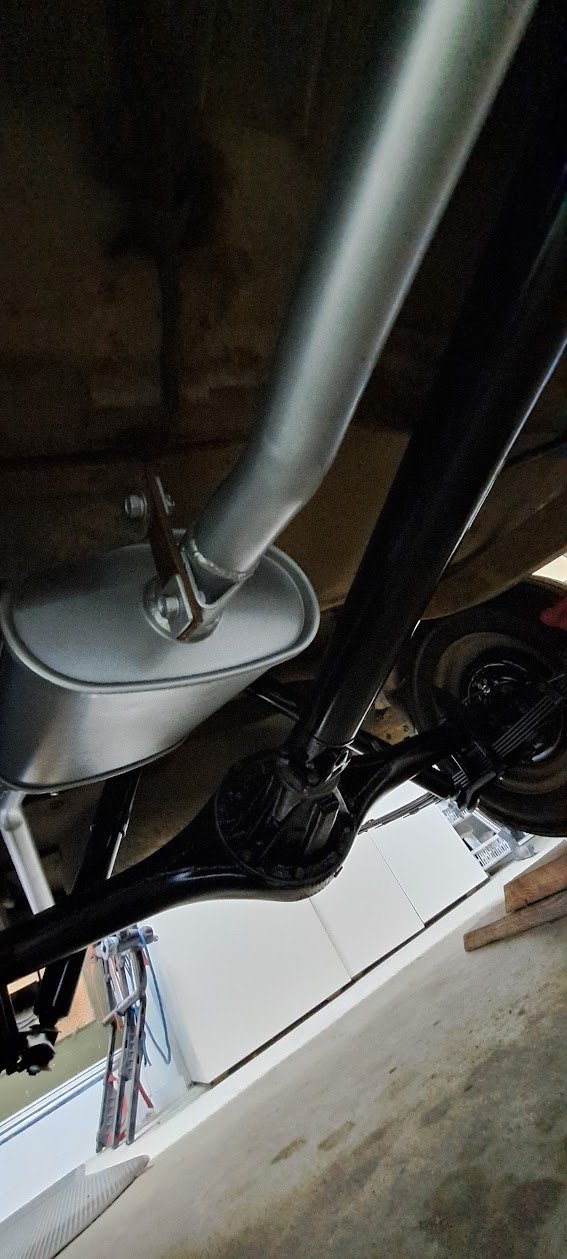
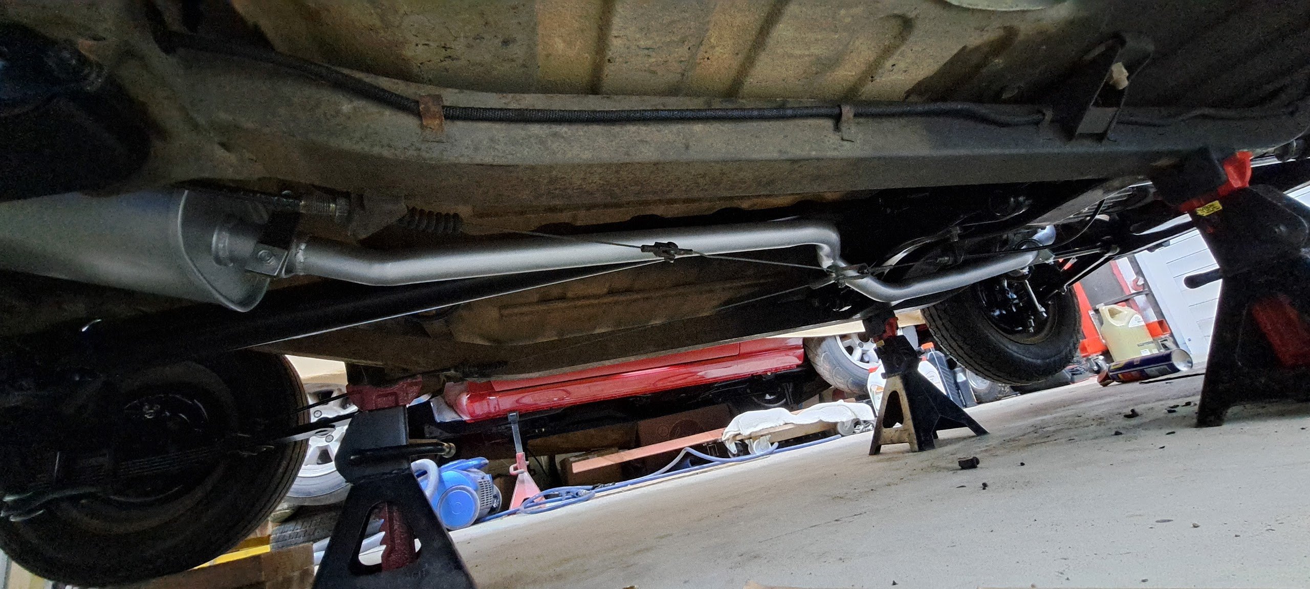
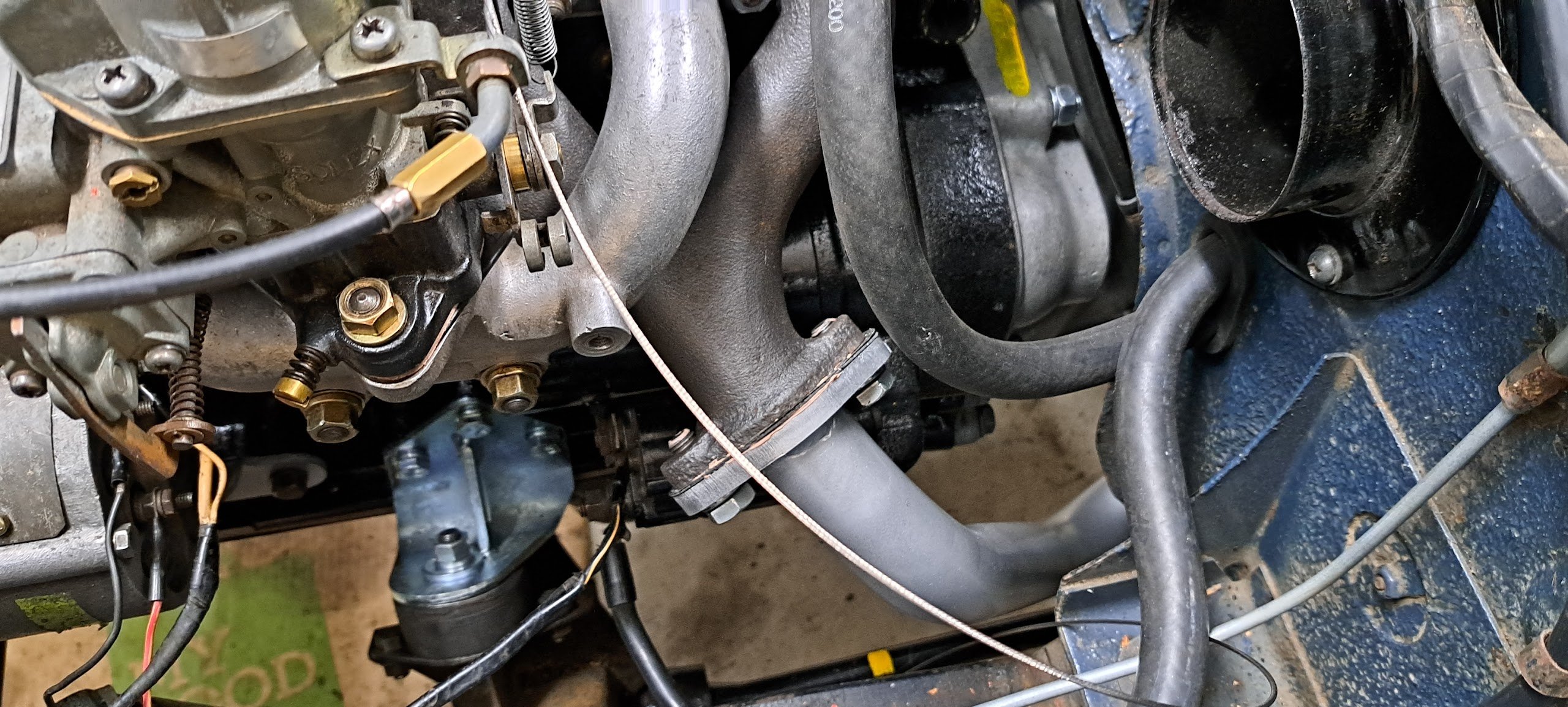
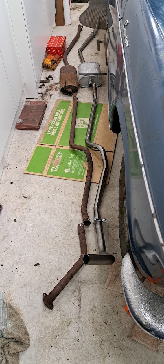
I got something kinky made last week for it, and fitted it this weekend Generally copied from what remained of the original - went with a big-bore inch and a half!!! Downpipe with mega flange jiggery pokery in here to clear the crossmember, handbrake cables and floor Oldschool hanger strap used More dogleg over the diff and out the bum Not too bad i recon for the 1st ever exhaust system I've done myself. Bendy kinky stuff done by the local east Auckland Mr Muffler who was superb to deal with and charged next to nothing for it.
2 points
-
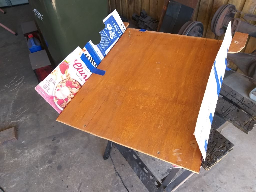
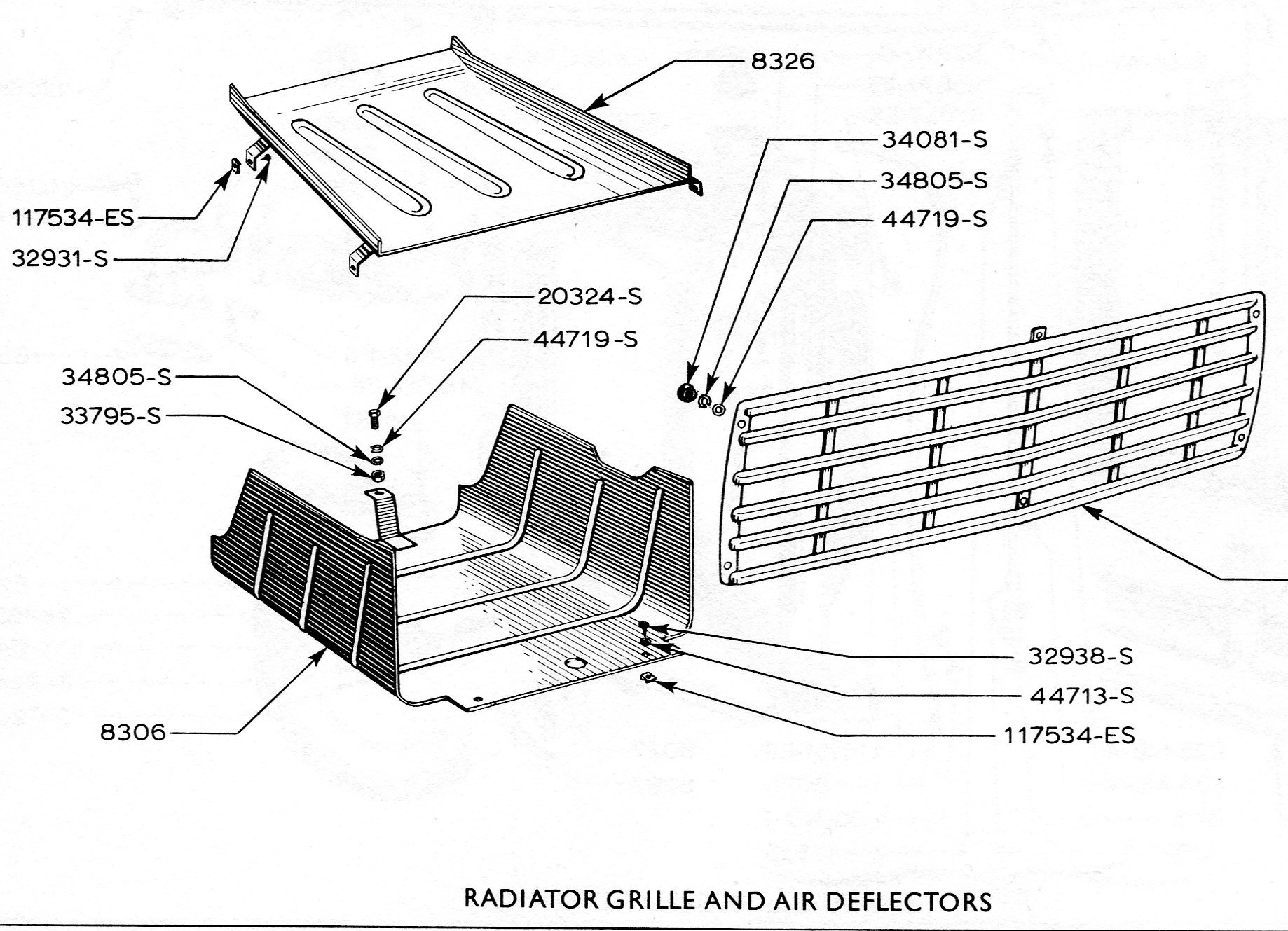
A few weeks back I was swapping a few yarns with Sandy who until recently headed up the UK based Thames 400E Owner's Club. Somehow, we got onto the subject of engine cooling and in passing Sandy mentioned a U shaped lower air deflector plate that was fitted from factory to all of the 400Es with the flat upper deflector plate only being fitted to vans exported to hotter climates. He immediately had my attention as my van has only ever sported the upper deflector plate. Sandy shared this image with me: Back in the day the UK boys used to run a standard Thames radiator to cool their mid mounted V8 conversions with many of them running no helper fan at all and never experienced cooling issues. Granted the UK is a lot cooler than Straya, but I've noticed that my van runs a little warmer than I was expecting and I'm thinking that its likely due to the missing air deflector. So while I'm in a bit of a holding pattern while the paint on my Astra pump brackets dries, I figured I'd make a start on my air deflector. Started off with some rough looking CAD work: CAD is a bit floppy, so the plan for tomorrow is to create a copy in plywood as a rigid mock-up. Thanks for looking.
2 points
-
coming along radly Matt!!1 point
-
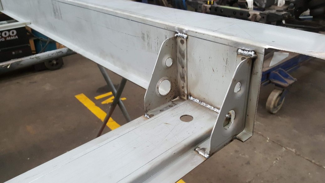
Very very nice fab work. You tig everything? Can I ask why?1 point
-
thought they had pics, but its all upper sills not the flappy bits, https://vehicleinspection.nzta.govt.nz/virms/entry-certification/reference-materials/non-structural-cosmetic-damage/sillsrocker-panels-minor-damage does mention this though 'A vehicle is not required to be referred to a specialist repair certifier if it has minor underbody impact damage as a result of ‘grounding’ the vehicle or some scraping of the sill seams." https://vehicleinspection.nzta.govt.nz/virms/entry-certification/i-and-c/vehicle-structure/threshold-for-requiring-repair-certification1 point
-
Lindstrom are magic. I still use more mine from 30 years ago. $$ tho. Duratech and Tolsen seem ok quality for not much money. Mako elec screwdriver seems good so far for light duty, no torque limiter though.1 point
-
I always thought that was the case too, but nearly every one we do at work gets the welds ground off. I can't see it being an issue, I have pictures of it all showing it's got a corner to corner weld, the top is just knocked off, so the full penetration to the edge of the parent material is still there. Plus half the original chassis is still underneath those plates, with welds between both parts.1 point
-
Nice Ironhead did you solve the clutch issue ?, I can see that over the years its become a XLCH that started life as a XLH , and that clutch pressure plate is off an early model ? with the extra holes where small studs would of been , so you need to check as their are three different spacer sleeve sizes for ironheads , make sure you have the correct length spacer tubes ? are the early pressure plates the same thickness? because seeing that early pressure plate on the 77 and reading about your clutch woes something is not adding up here , I have a 74 xlh with a mustang tank like you brought your bike with , their not very common , quite hard to get , enjoyed your blog cheers1 point
-
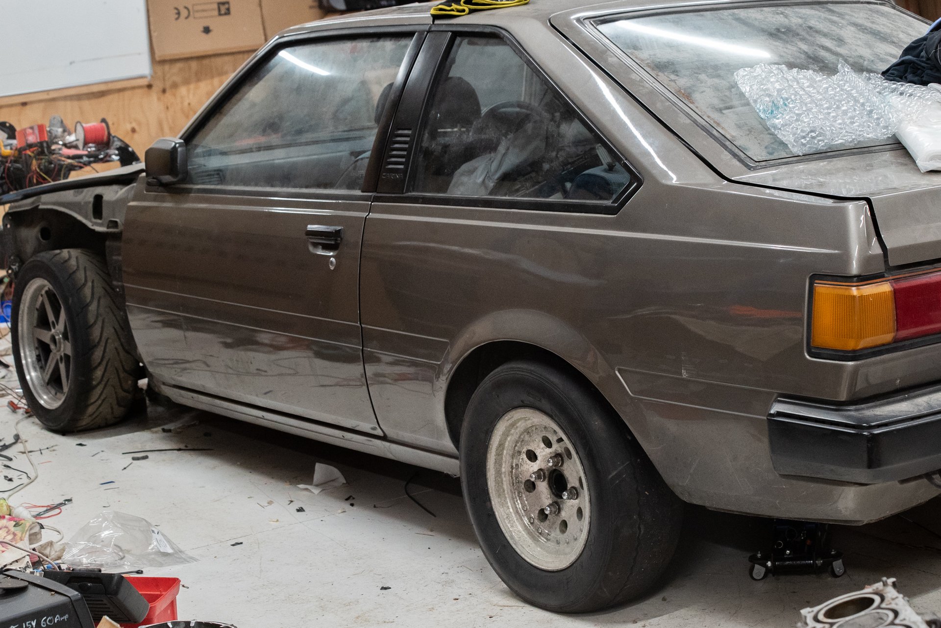
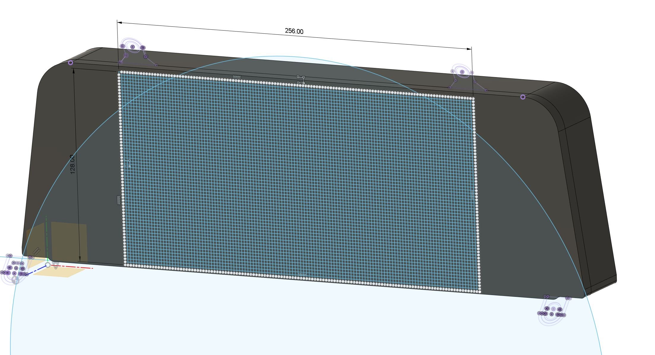
A few things going on. Most of the wiring is tested and working well. A few mistakes I made with wiring order which were easily remedied thanks to being able to repin the sub loom plugs. The TPS on the second set of throttles, runs absolutely nothing like any TPS I've seen before, which is annoying haha. It wasnt simply two voltage divider circuits. It uses some fancy chip that looks at the field lines coming off a magnet that rotates, then draws two sine waves that get compared by the ECU to determine throttle position. Or some crap like that. So, that's off to the bin. I will need to print an adapter to put a second "normal" TPS on there. But it's been annoying that I havent been able to test my ethrottle controller yet. Since it's a small fiddly part that needs quite exact tolerances, I shall borrow a favor from @flyingbrick who has an awesome resin based 3d printer. The dimensional accuracy is amazing, he previously printed me a fitting to go on the end of my valve spring compressor tool. Which worked great, and showed no signs of wear or damage after fitting 24 very stiff springs into two heads. Thanks Nathan! Also, I found a cheap set of bogan spec 13x7 4x114 Cheviot US800 wheels that I can fit my drag slicks onto. So that will be cool. Hopefully I can make it to December OS Drags via tech inspection. Even if it means the car will need to be running with standard cams and the crappy factory exhaust manifolds or whatever. Fingers crossed I can keep the momentum up and get things done in time. Another thing is that a while ago I decided I want to run a digidash instead of a factory one. So I made this which worked out quite well and was cool. But I felt like the styling wasn't quite right, and I somehow wanted to use up more of the space on the sides. But couldnt quite think of how to achieve that. In the meantime, with the Echo. I discovered just how absolutely magnificent it is, to have a graduated shift light where the bars start from each side, and meet in the middle. The accuracy on shifting is really amazing. So I have been looking into how I can incorporate some LED bars into the shape. But, then I went a bit further down the rabbit hole and figure that instead of using an LCD screen (which was 800x480 resolution in the above case) I have found that you can get 2mm pixel pitch LED screens which would be super cool for this I think. So I've found a screen that is 256mm across, and 128mm tall - which is a pretty damn good fit for the carina dash: (The circle indicates the visual block caused by the inside edge of the steering wheel, so outside of that is fairly useless space) Previously I was trying to emulate the sharp edged aesthetic of a fixed segment LCD display. However this will end up looking a bit more... Commodore 64 or something. haha. I'm not 100% sure if it will work out how I'd like, but it will be fun to play around with. There is already a really awesome library written for it, to run on a Teensy 4.0 which can render things crazily fast. One issue with the LCD screen I was previously using is that the refresh rate was fairly crap. Which is why you cant have things like a shift light/bar just represented on the screen. It's too slow. But these LED screens have an insanely fast refresh rate, no problem. So I can incorporate my shift lights directly onto the screen and it will be super fast. Here's a video to get the general idea:
1 point
-
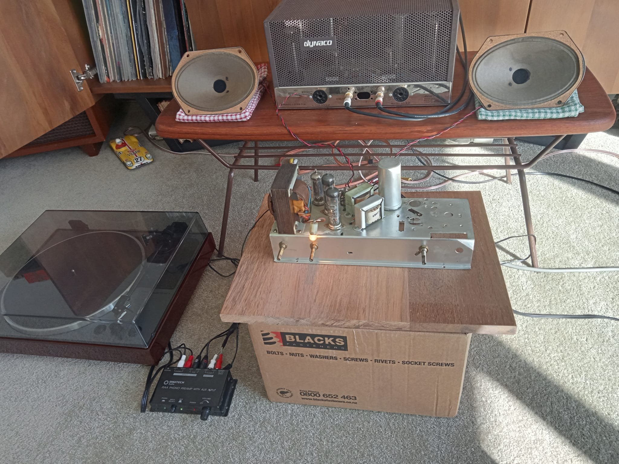
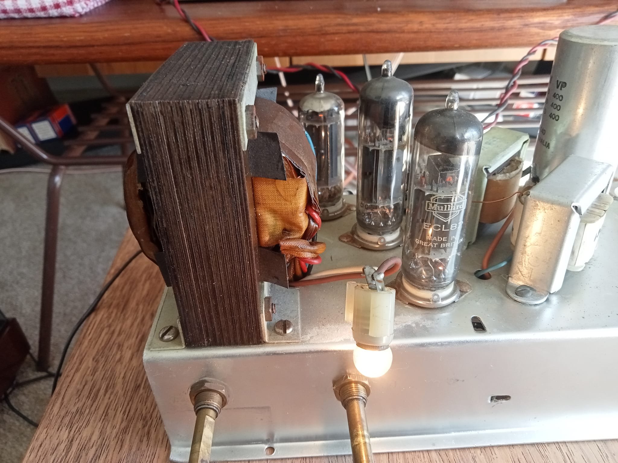
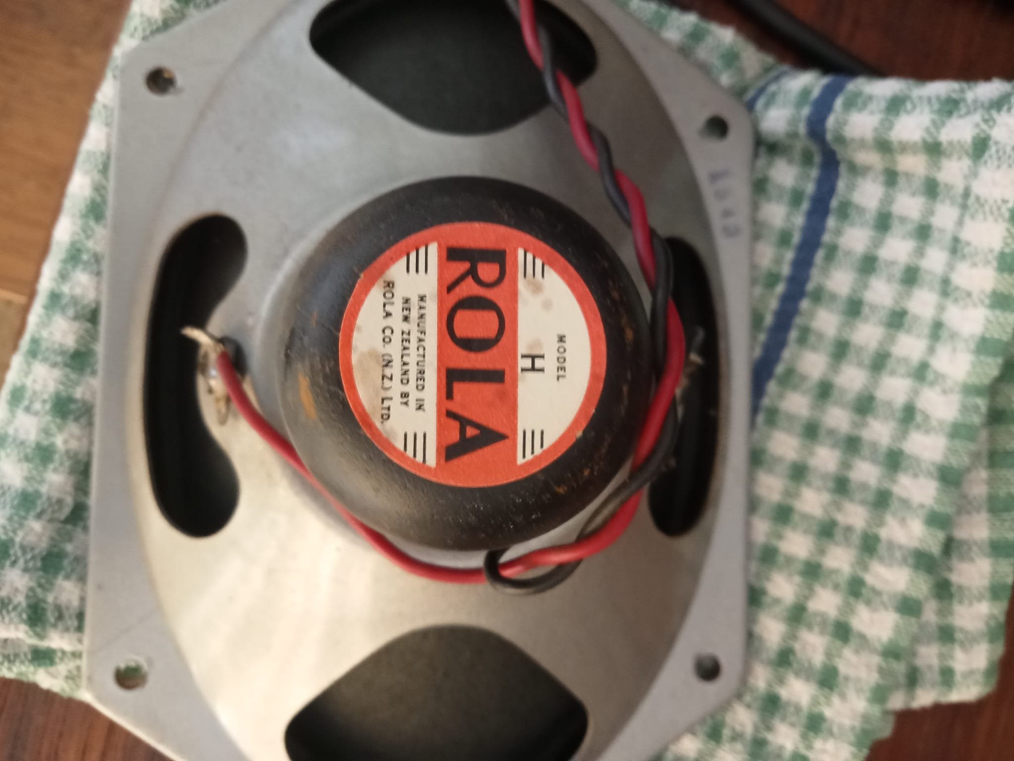
After picking up this old stereogram chassis from the bin im feeling very pleased with myself today that i successfully remove all the radio parts and put a new plug with killing myself and these old rola speakers sound great as they sit ,mids and highs awesome, low frequency not so much,
1 point
-
Only had a few hours in the shed today so spritzed the final coats on the carby hat. I should be able to present it to you in glorious technicolour tomorrow. In other news I've been fine tuning the Astra pump bracket. It had a little angled section that was quite close to the engine and didn't seem to be serving any purpose. So, I pulled a bit of a van Gogh move and the little ear is no more. Have replaced it with a straight piece since taking this photo: I then tackled a bit of CAD and I now have this pattern for the bracket that will bolt up to the rear wall of the engine box: I've run out of welding wire and I don't have a big enough piece of steel plate to create my bracket, so it's off to town I go tomorrow for some extra supplies.
1 point
-
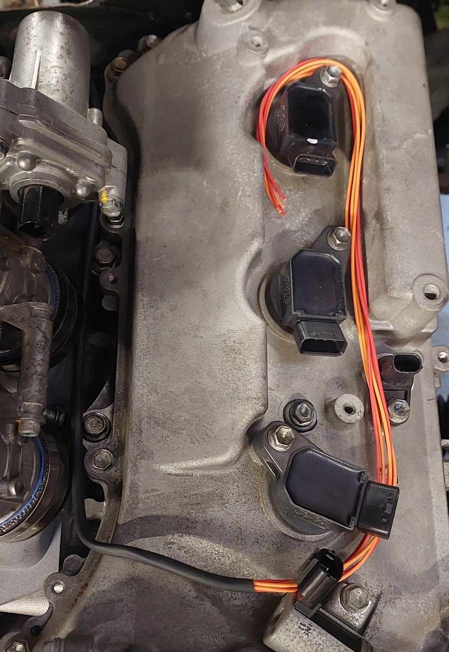
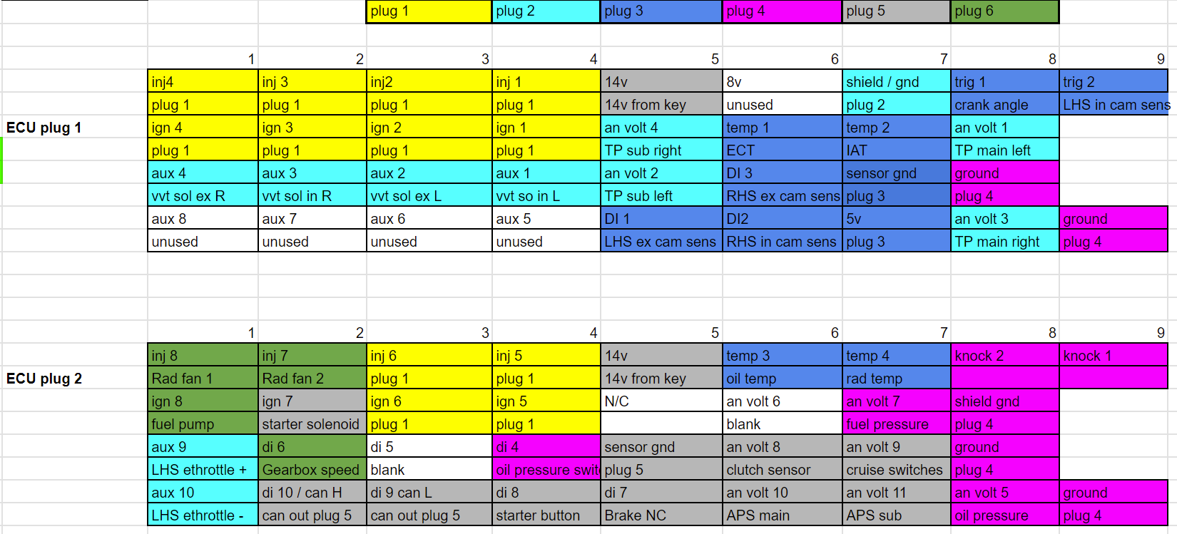
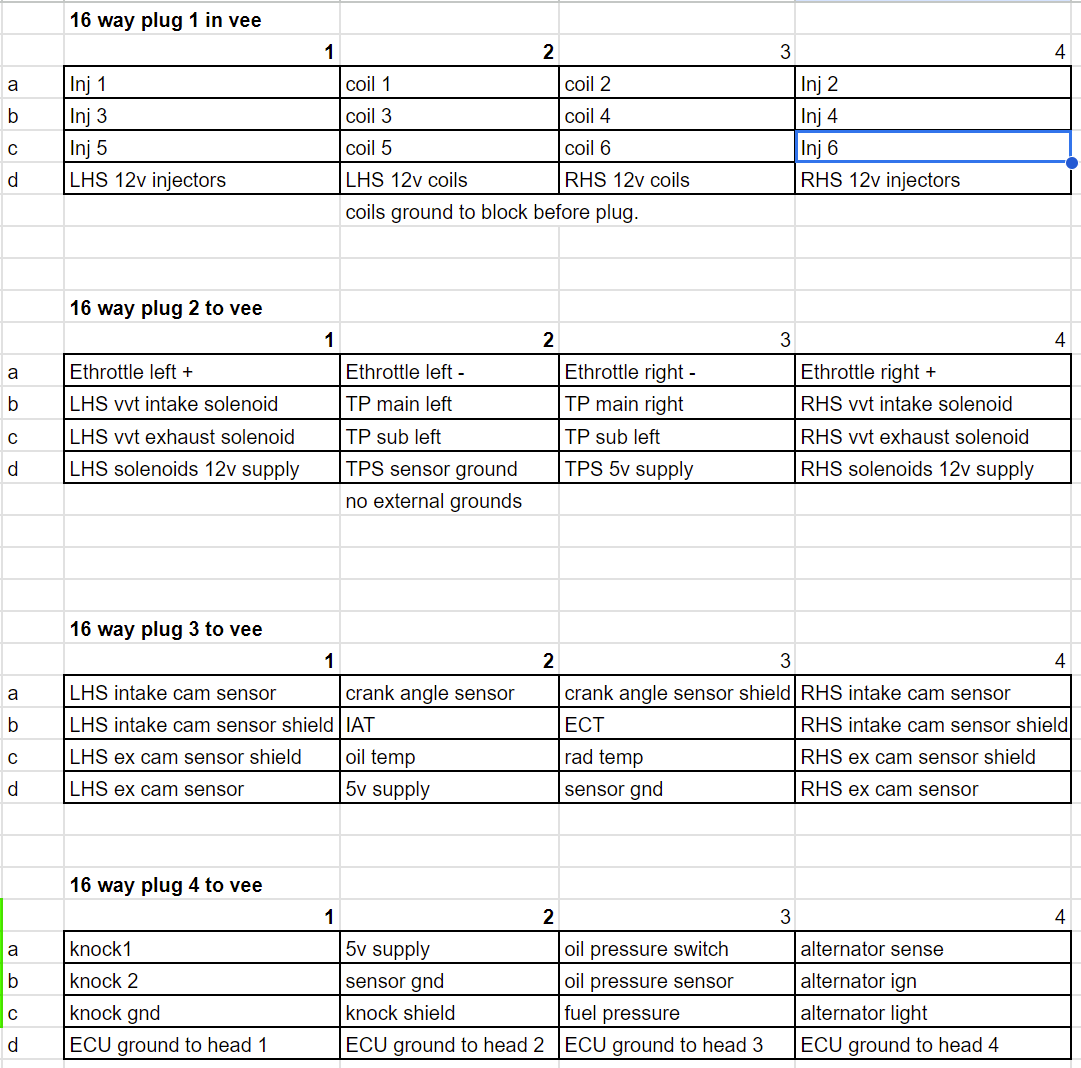
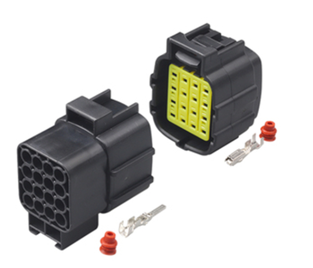
I managed to get the radiator sitting a little lower, so I actually think it will be okay even when engine sits down a bit more. I had a mix and match of various driveshaft pieces, and have managed to put something together that is the right length. Sweet! The UJs seem okay but I should probably get them rebuilt so I dont have another incident. breaking the front UJ at ~80kph was scary. I've started on the loom. I'm gonna have 4x 16 way connectors that live in the vee of the engine, like this: then 2x 12 way plugs on the cabin side that connect the ECU to other stuff. What I found on the last loom that I made for the echo. Was that although I tried to make things tidy, the plugs into the ECU were messy because things unnecessarily crossed over a lot. So for starters, just trying to allocate everything to the 4x plugs. In a way that makes sense for position in engine bay. And keep the higher voltage stuff away against shielded signal wires or whatever. Then I've just allocated everything fairly randomly to relevant pins on the ECU and see how it lays out. Then reorder things so everything is grouped together as much as possible, so the plugs dont become a god forsaken mess like every other time. This has paid dividends as it made it easy to see that if I just swap around input 1 for input 5 (or whatever) then the grouping improves considerably. Also, it's made it way way way easier to actually make the loom - Firstly because it's broken down into 4x sub looms and each of these are smaller, less intimidating tasks. Then secondly the main branch of the ECU into the engine bay is just a straight run ending in 4x plugs. Rather than branching out to everything. So it's way easier to test and trace the individual sections. I've already finished the first sub loom, for injectors and coilpacks. Fairly quickly because it's so much easier when you're working to a plan. Maybe this is why wiring diagrams exist? Who can say? Injector wiring looks fairly discrete which is good. The coilpack wiring is a bit more obvious, (waiting on some more terminals to finish it) but should hopefully still look nice and tidy. These days I prefer to just stay with more thinner branches rather than trying to incorporate everything into one. Partially because I always end up chopping and changing my looms around. But also 4x smaller branches end up considerably more flexible and easy to position. As I'm not using tefzel wire that easily slides against itself to make super flexible motorsport spec looms. (TXL is a cheaper automotive spec alternative) Hopefully I'll get most of this smashed out fairly quick once some extra terminals turn up.
1 point
-
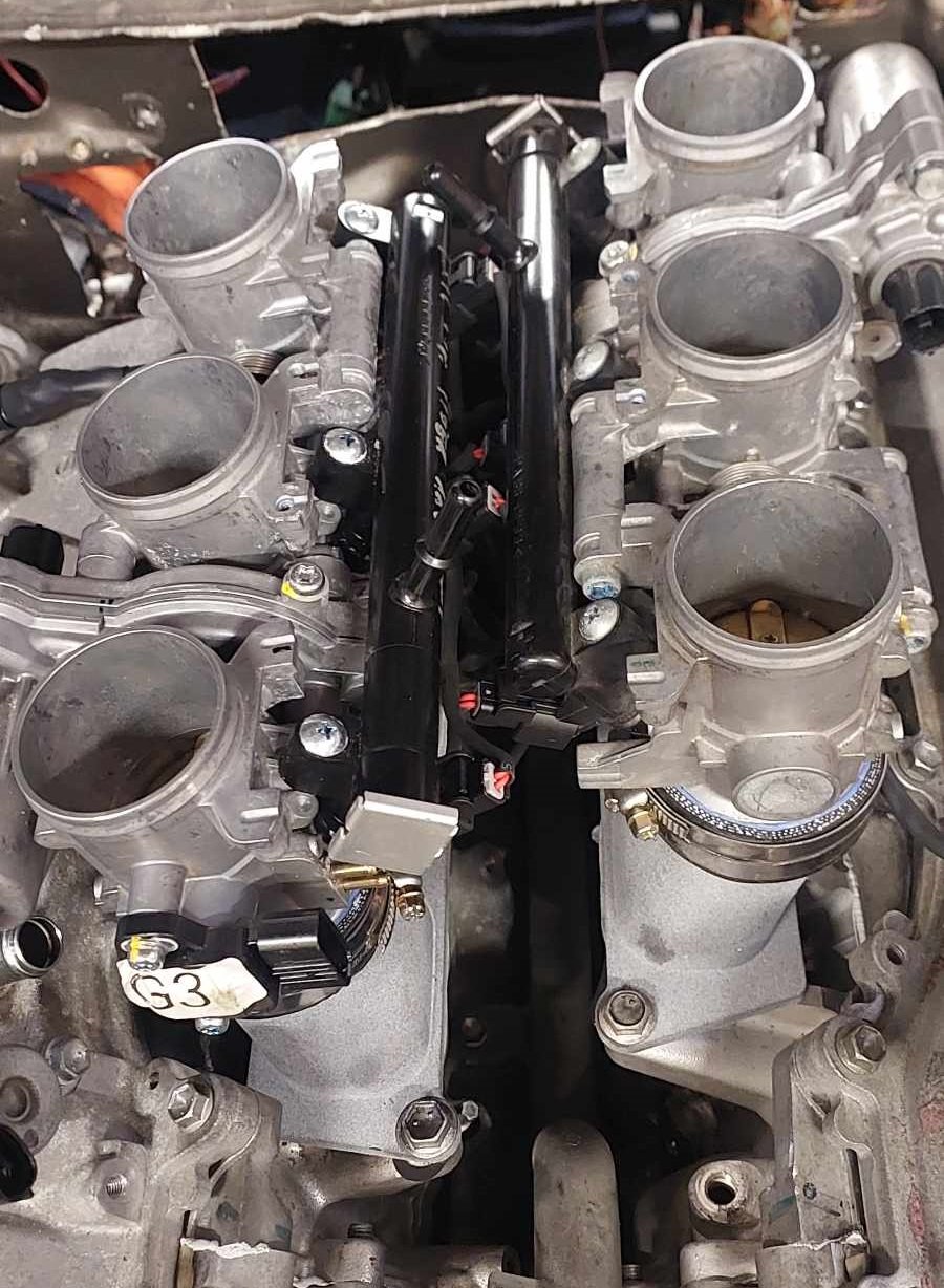
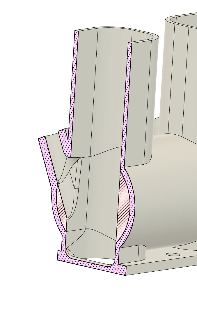
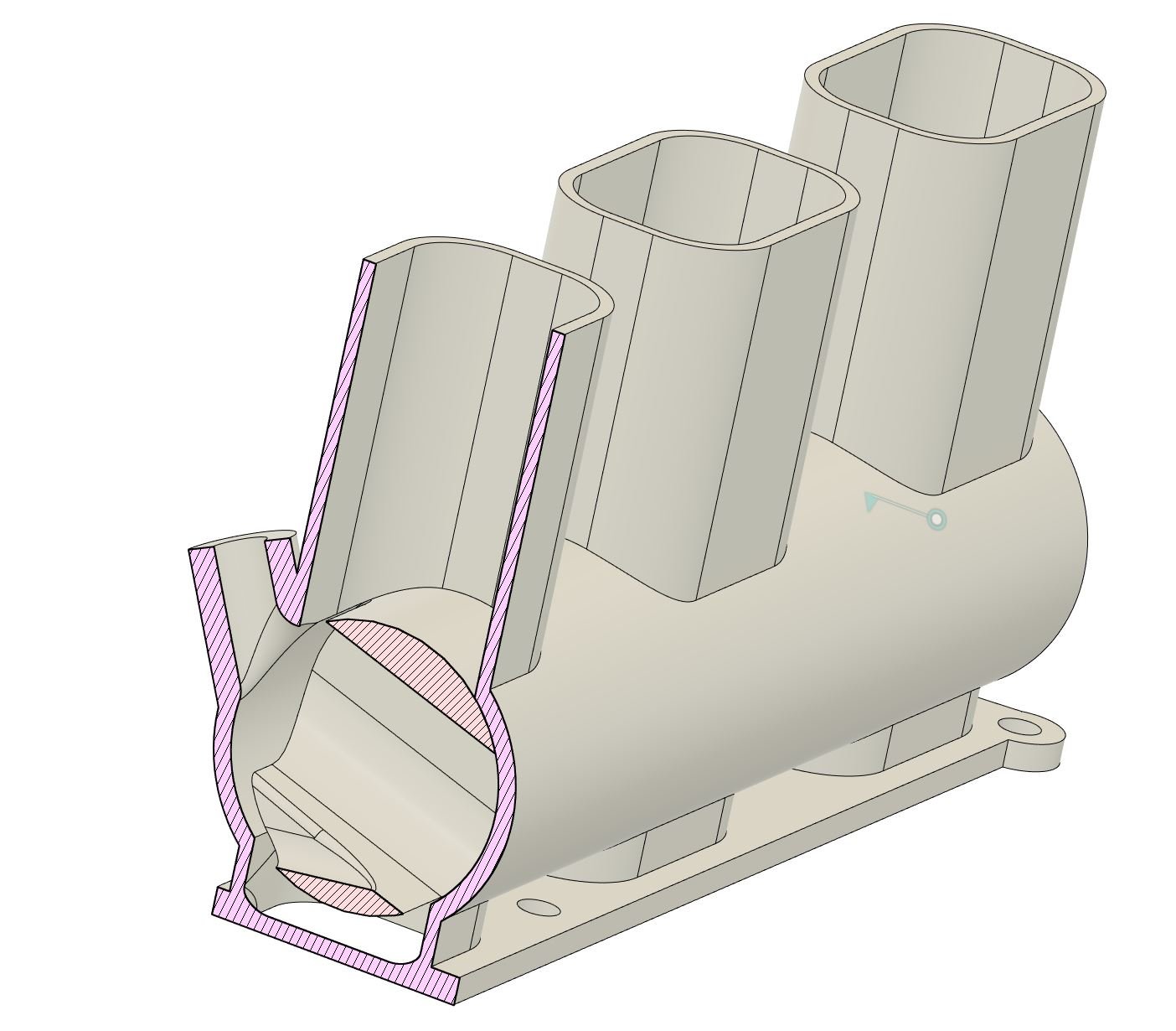
My current intake setup will get the ball rolling, but, I think throttles are probably too small. The centers are less than ideal and the fuel rail position is uncomfortably close to the bonnet. But the quality and strength of the print of the manifolds, from the 3rd party print has blown my mind! So good. One thought I've had is to get 6x tiny ethrottles and control them all individually for lolz. Otherwise, been thinking. Can you print entire throttle bodies, rather than just adapters? Well, Not really. Because the problem is that you need a super thin metal throttle plates. So that lends itself to being metal or similar only. But do you know what usually sucks to make out of metal? Barrel throttles. Barrel throttles might be entirely printable, or partially printable (either just housing or barrel) because there are no thin parts needed. The thickness of everything is liability from metal but a positive for printing. There's (I think) going to be less thermal expansion compared to aluminium and so hopefully less chance of throttle sticking. This would help with my bonnet clearance issue, as I can mount throttles further down towards the head. My current setup needs to be mounted high-ish, because otherwise the transition is disgusting. Barrel throttles can be a non circular profile no problem so you can just have them the same shape as the port all the way up. Anyway, thinking something that looks like this. Bong shaped intake, paying some homage to my West Auckland cultural heritage. Maybe I could make some trumpets out of 8% woodys cans. Another problem with barrel throttles is that at part throttle they can end up pooling fuel in the barrel section, then having a hernia on full throttle when it tips it all in. But I figure you dont actually need both sides of the barrel to seal, and these will be vertical. So injecting inside the barrel itself and having the rear half more open would probably be sweet. At part throttle like this: The barrel shape itself is still quite simple to allow for the injector. But ends up being a decently solid part without any delicate sharp edges anywhere. (Shape obviously gets more complicated to allow for bearings and TPS etc etc, but you get the idea) Probably a project for the distant future as I've got my hands well and truly full currently. But would be pretty cool, have always wanted to try a barrel throttle.
1 point
-
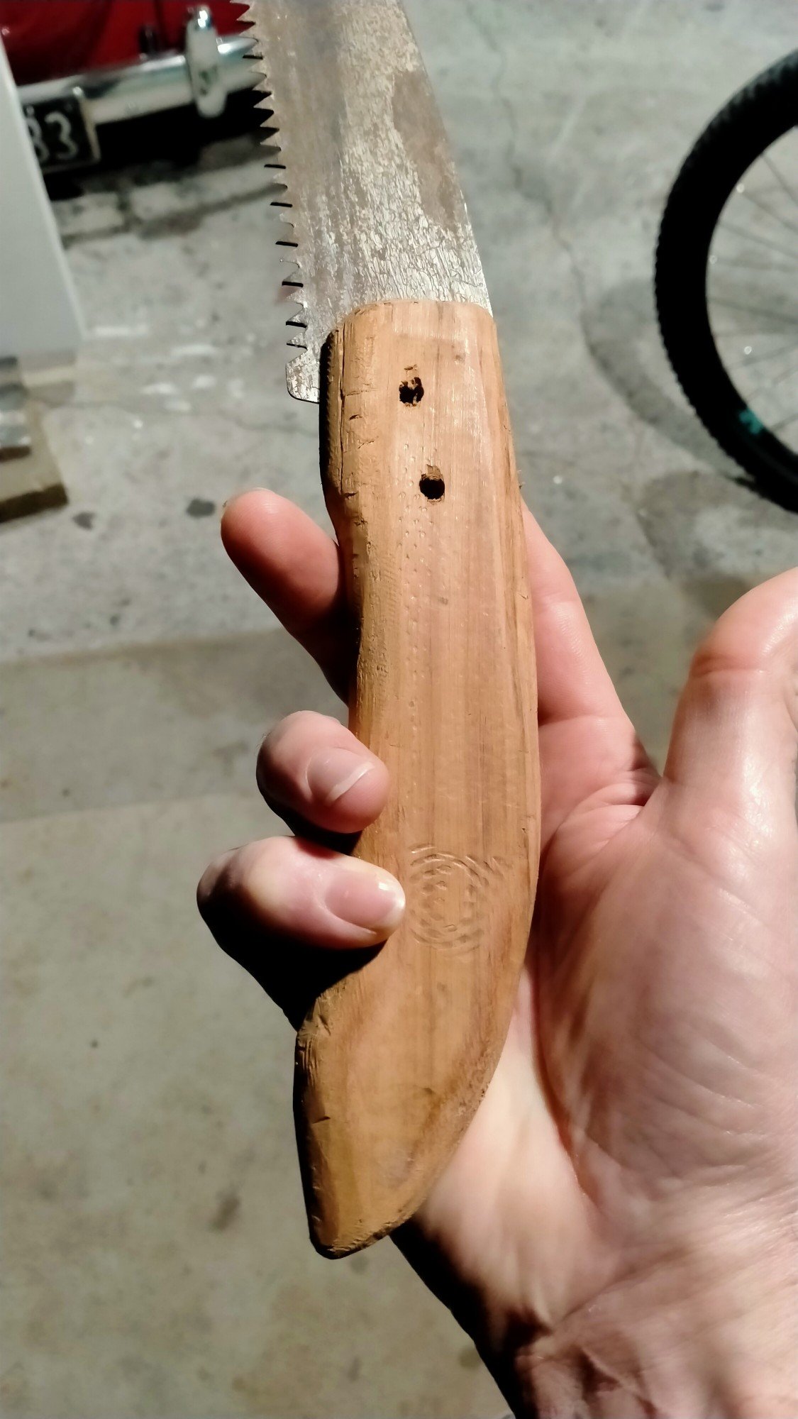
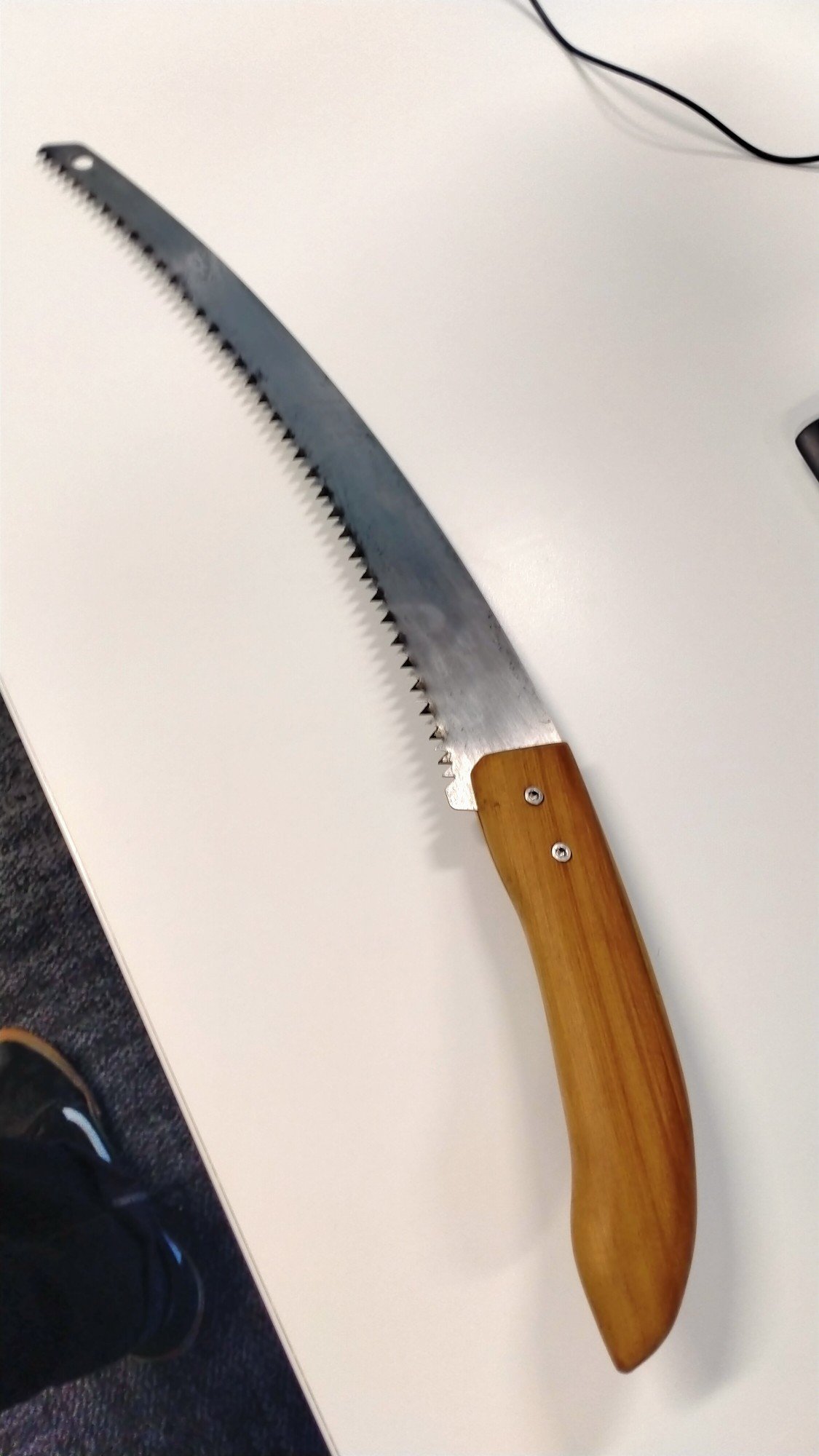
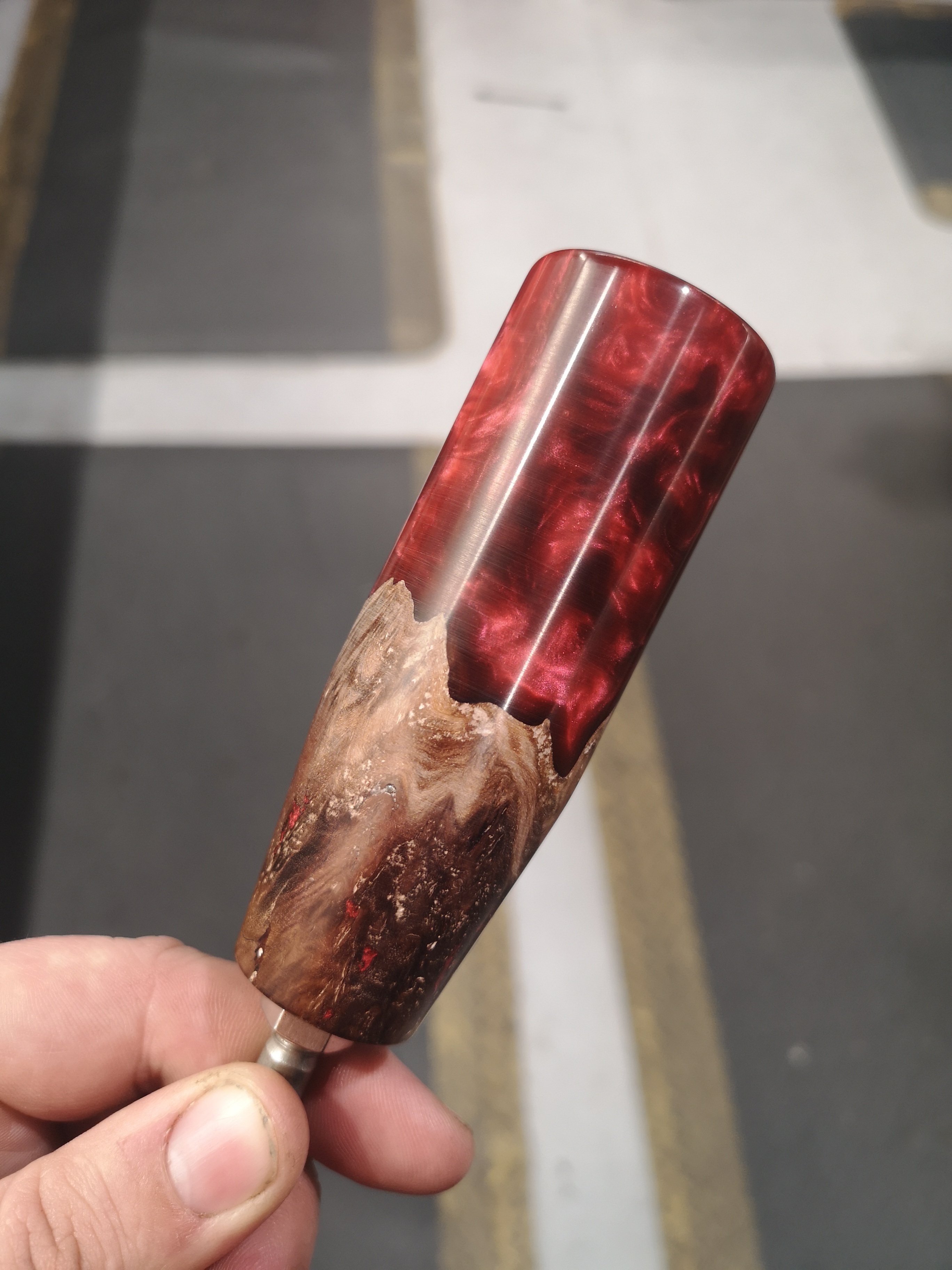
Was doing some yard work a couple weeks ago and my cheap tree saws plastic handle feel apart. Whittled this out of a old piece of the house, on Saturday the neighbour who is into his woodworking helped finished it. Came out nice, looks great, fits your hand mean. Could have just bought a new one but this was heaps better.
1 point
-
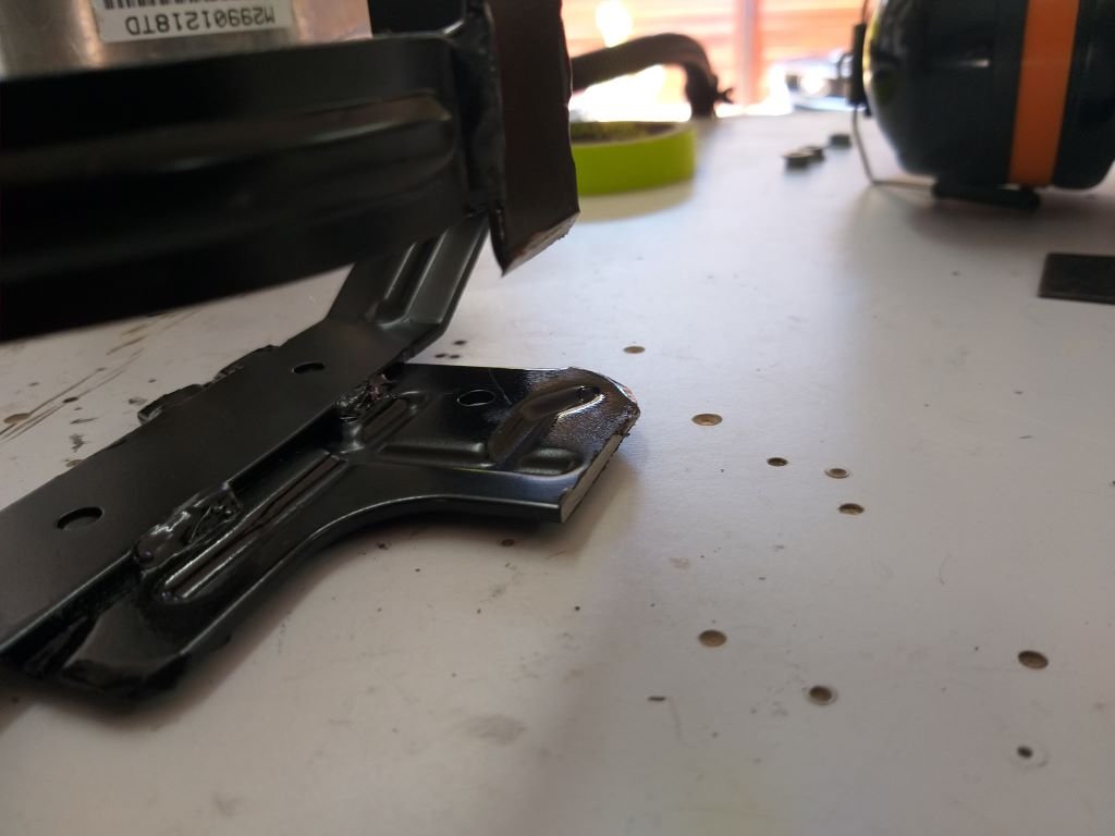
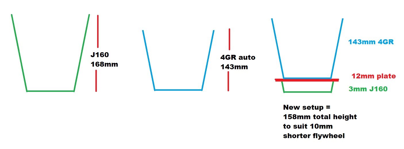
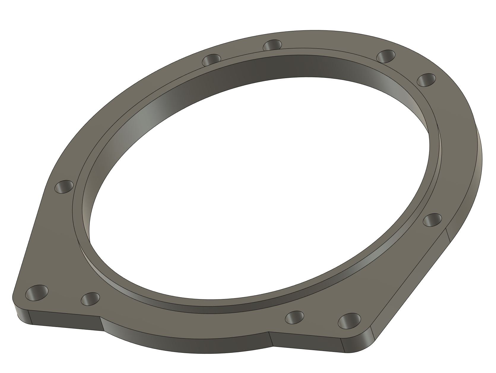
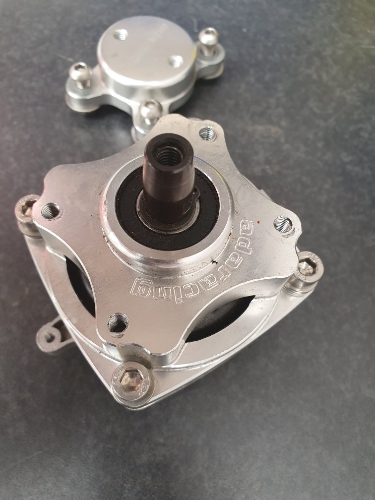
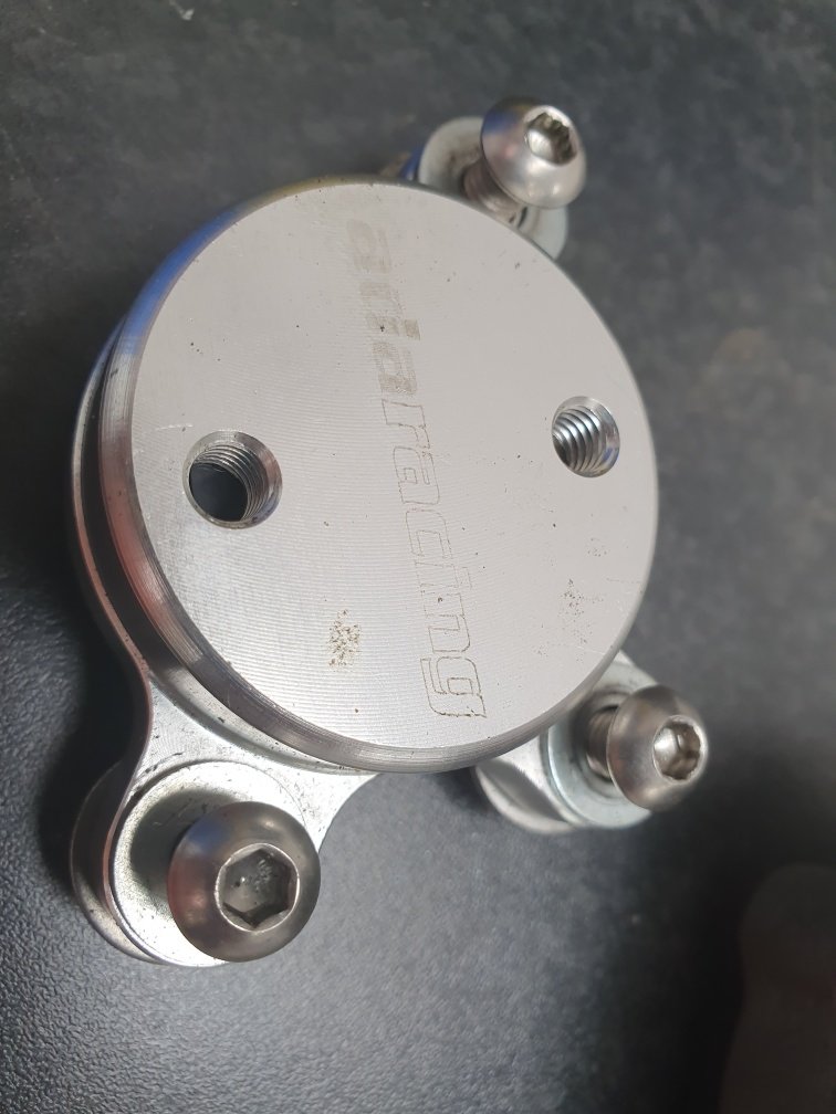
Alright so one of the reasons I've been dreading dealing with the bellhousing situation, is that usually things are located with 2 or three dowel pins, and then held together with bolts. The problem is that unless you get the dowel position exactly correct to the centreline of the input shaft, it can end up being way off. Then you might end up having problems like the gearbox runs real hot, or keeps wearing out bearings or whatever and wont necessarily know why. So, I think the universe decided I deserved a bit of a win after the adventure of aquiring the box. Because the Mark X auto box doesnt use dowel pins or anything like that, to locate the bellhousing onto the gearbox... It just has a giant circle, and a giant round hole that press up against each other. Too good! So a bit of brain storming with a few mates and taking some measurements, I think I've got a plan. Basically the J160 bellhousing is 25mm longer than the Auto one (hooray) So I'll basically cut almost the whole thing j160 front off, and weld on a flange/ring that will be easy to position relative to the input shaft hole. As the bellhousing wont be in the way. Then the bellhousing locates on the ring, and bolts up. Sweet! Also this bellhousing pattern is bloody easy. Both sides are symmetrical and it's really easy to index their positions relative to the round hole. So something like this will end up welding onto the gearbox. I am thinking could use a second plate in the middle that also slots into the input shaft hole of the gearbox. So it will be exactly central. Then once it's welded on, the bellhousing can center itself on the ring, and bolt into the correct place easy as! The only issue will be that there's no hole for the clutch fork to go through, and will need some bosses welded on for a slave cylinder. EDIT: no, the existing slave cyl holes will work as they are further back. Sweet. So I'm gonna chop up a bellhousing, print a test piece and then I'll hopefully have @Stu be able to work some magic with machining and welding etc. Pretty awesome that this looks like it'll work easily, as long term I've always viewed this sort of job as really difficult / above my paygrade.
1 point
-
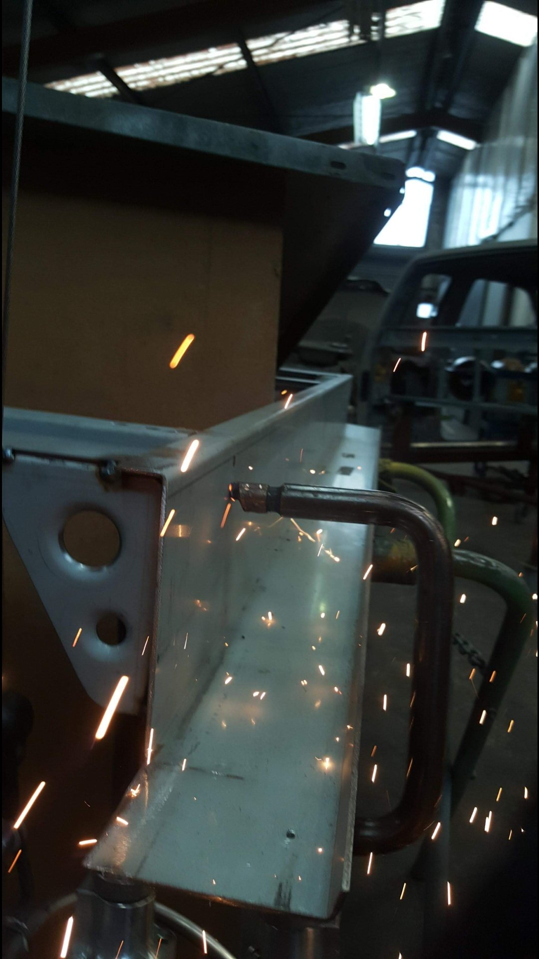
Plasma cut some c-notch plates Top of c-notch filled in and made a start on the new crossmember up front. Upper link brackets welded on to the crossmember. Cut off the old spring perch's from the lower arms and made some pedestals for the airbags to mount to. Before I cut off the old mounts, I made a jig out of angle and box section to locate the body mount holes so I knew where it went when I made the new mounts. All tacked together with the airbags in place. Much better height now, front still doesn't have the drop spindles in it, so that'll bring it down a touch more. Body back on for test fit. Some tiny clearance issues but nothing major!1 point
-
Now summer is here….. thoughts turned to making our picnic table usable. I made it about 14 years ago from nominal 2x4” pressure treated softwood. Some of it turns out to be more effectively treated that others. Casual inspection suggested it was mainly the table top and bench rails that were done (and some were very done) so I optimistically went out and bought some decking timber to resurface it. Then I came back and went to work…. The parallels with car restoration were immediately obvious. Loads of snapped fasteners, and loads of unexpected rot in awkward places. I forgot to take a before pic, so you’ll just have to imagine a well-weathered picnic table….. Part way through, zone of maximum pieces. Devastation. No picnic table recognisable. Thought I was going back to the wood shop…… but careful examination showed that there was easily enough sound timber, in the top and benches ironically, to remake the structure, most of it in fact. Then reassembled, this time sloshing the joint areas (worst rotted, just like cars) with preservative. Here it is…. Even got some ok-ish timber left over. And a lot of crumbling shrapnel.1 point
-
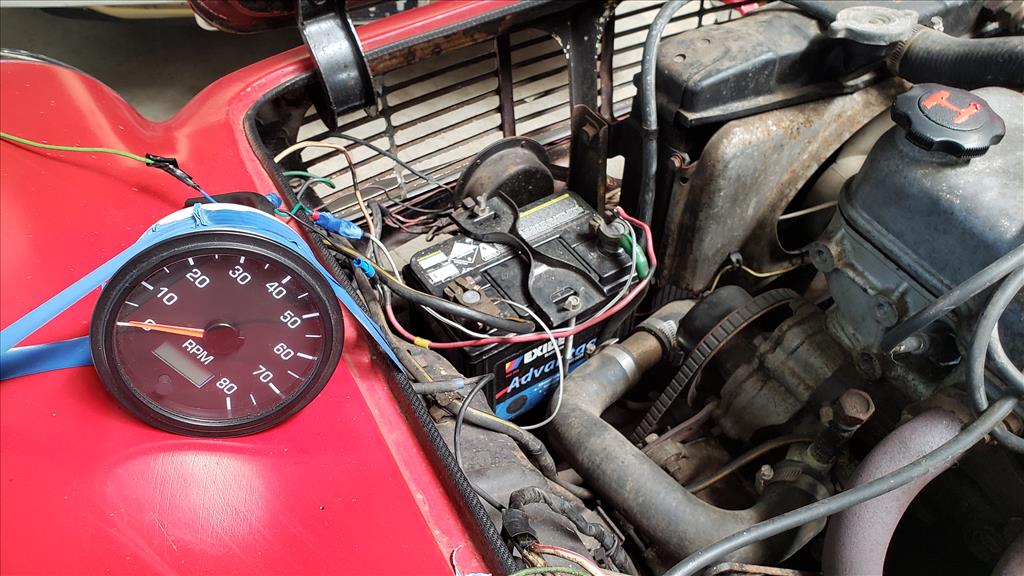
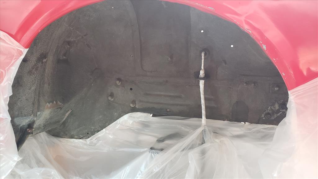
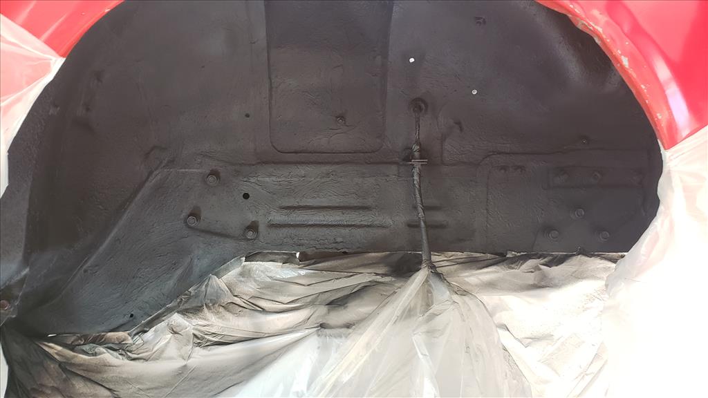
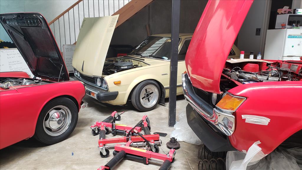
Today we're team red! First up, while the front end is apart on the Celica I decided it would be a good idea to put some undercoat spray in there. First I cleaned up with some scotch pad and soapy water and glad I did as the water that came off that was nasty. After that simply waited for that to dry off and spray on the stuff. I used a Sika product and it sprayed really well but was only enough to do light-ish spray on both sides. As you can see on this side it's still a little patchy so I've ordered more. Not sure if people usually do the guard side as well? There's no guard liner so might as well. Made some great progress on Barry too. I was able to work out some more of the wiring situation by doing some sketchy shit and got the tachometer working so that's cool. No idea how accurate it is and it's some kind of machinery unit as it has hours in the digital bit below which is funny. Then I started to do some CAD (cardboard aided design) work on the new dash panel. I had to do some clearancing behind to get the furtherst right 2" gauge to fit but looks like my plan will work great in general. Unfortunately it seems like the speedo cable is not connected at the gearbox end as it doesn't spin when the car is in gear so I couldn't get the speedo working today. Bonus content
1 point
-
So good for heating knives, ah, so I'm told.1 point
-
Been a RC plane nutter for a few years, found this plastic case and convert it to a box to transport my 1 cell (3.7volt) RC warbirds, protected and lightweight. Another of my obsessions, Veedubs, found a way to display my mainly tail light but also other Veedub stuff. Have plans to get some LEDs and light it up. Speacking of lights, the boss lady even approved of this one, let this in the house, well out on the veranda at least! Used a big valve as the base, the middle tail light from a 1961 model Beetle, rare 50/50 only one year in Australia and Italy.1 point
-
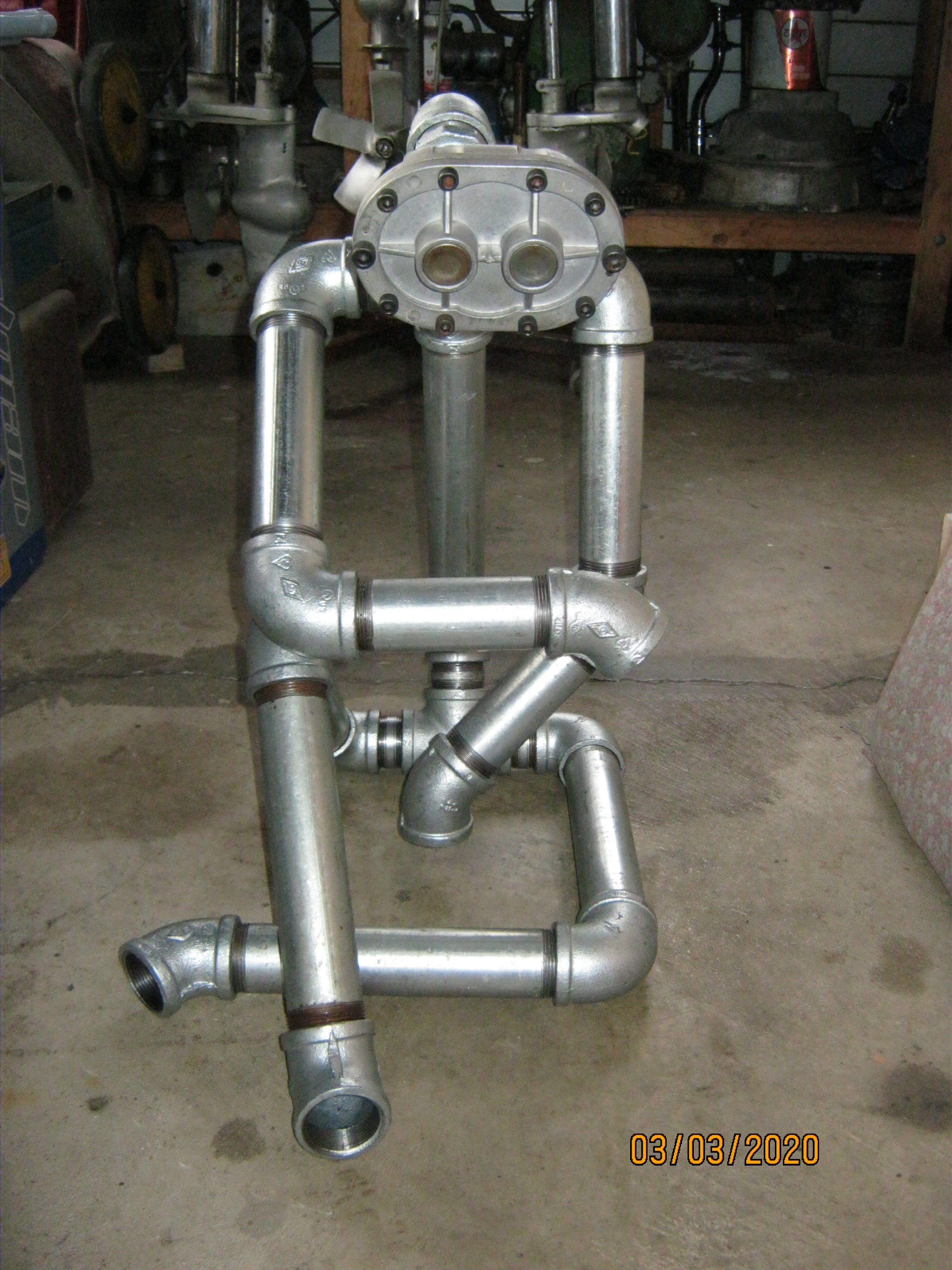
I was quite taken by a pipe guy on the instagram pics & vids thread so built one for my wife. Working out a lady to go with him now.
1 point
-
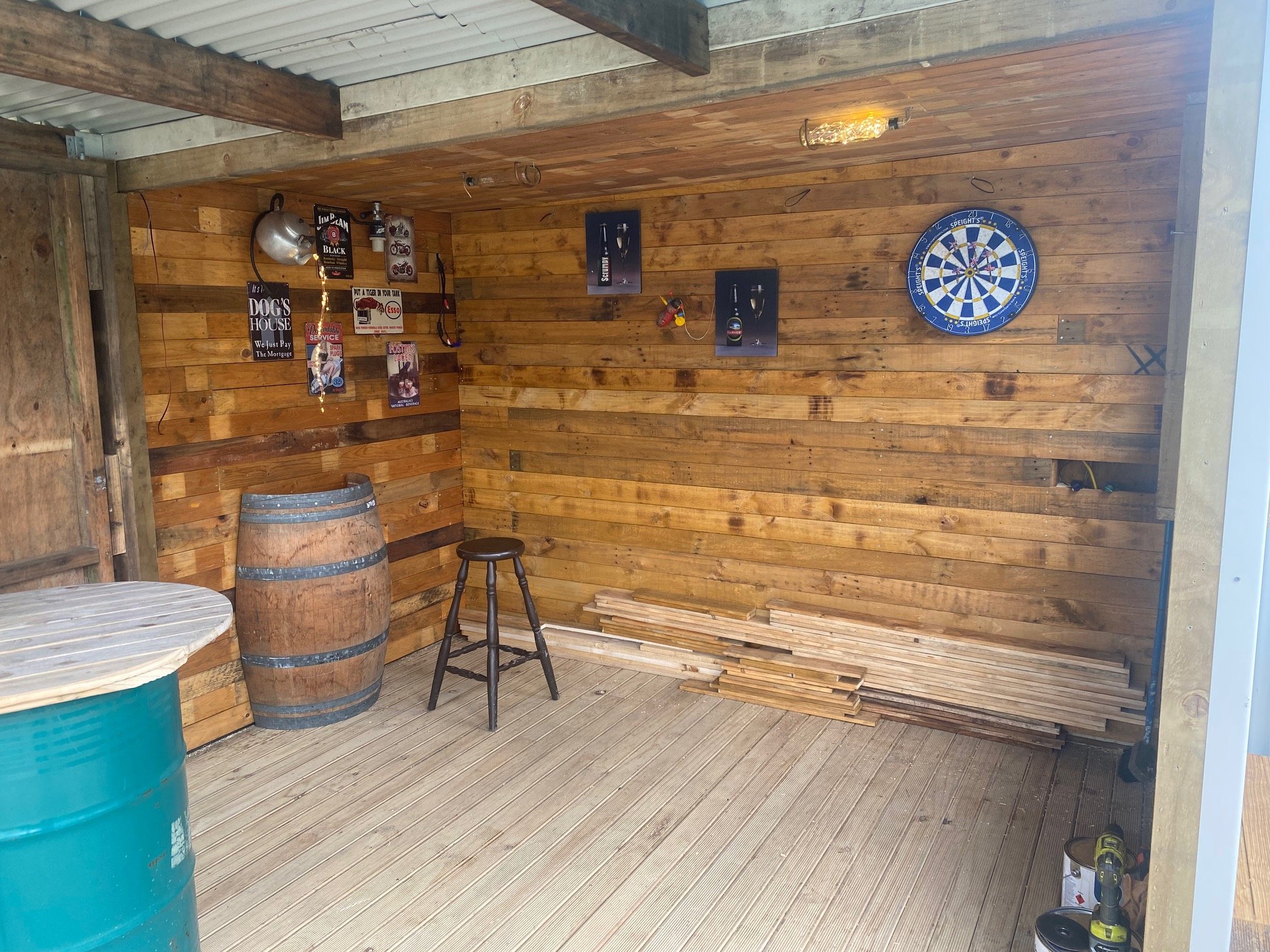
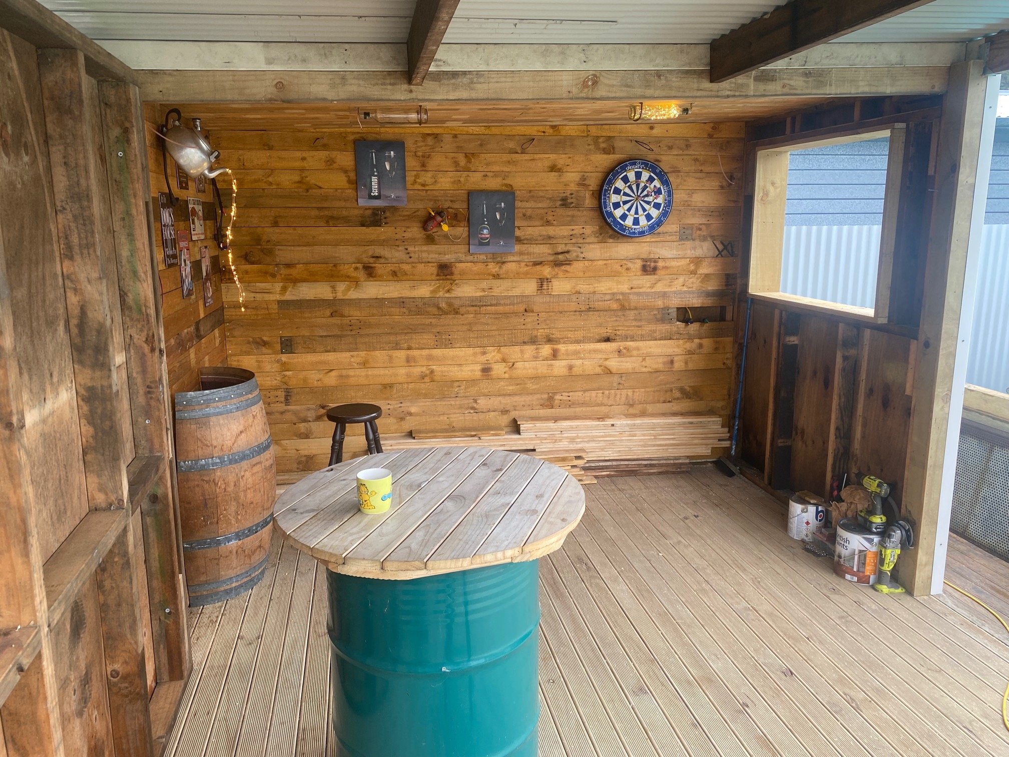
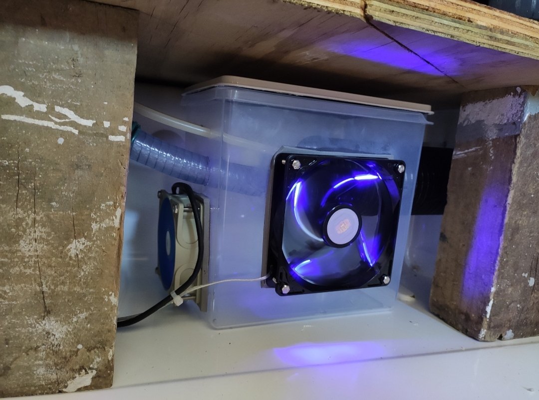
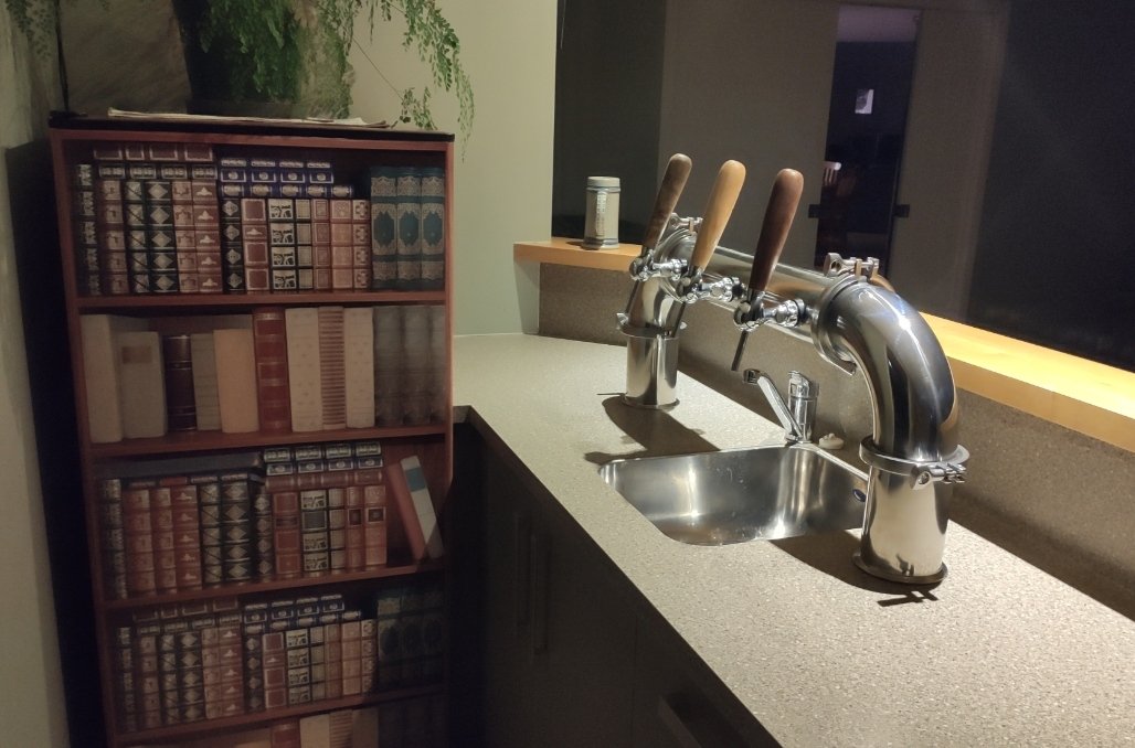
And here's what the inside of the fridge/airbox looks like: And as finishing touches I vinyl wrapped the serving fridge and spun up some new tap handles: Kauri Puriri Final product:
1 point
-
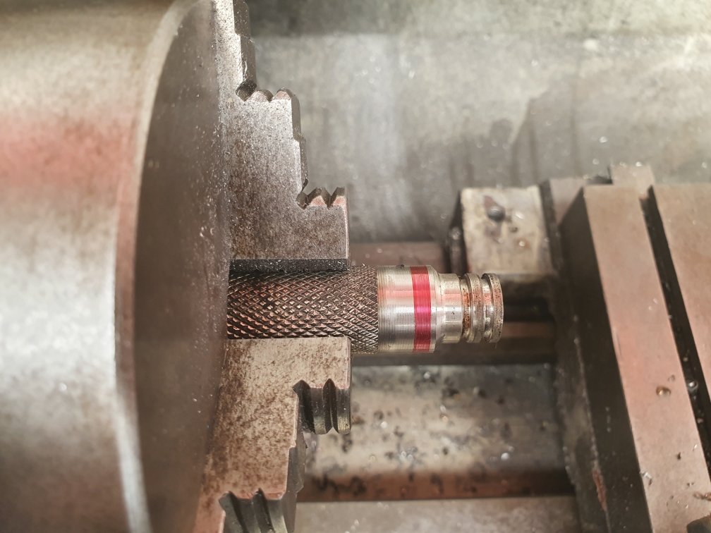
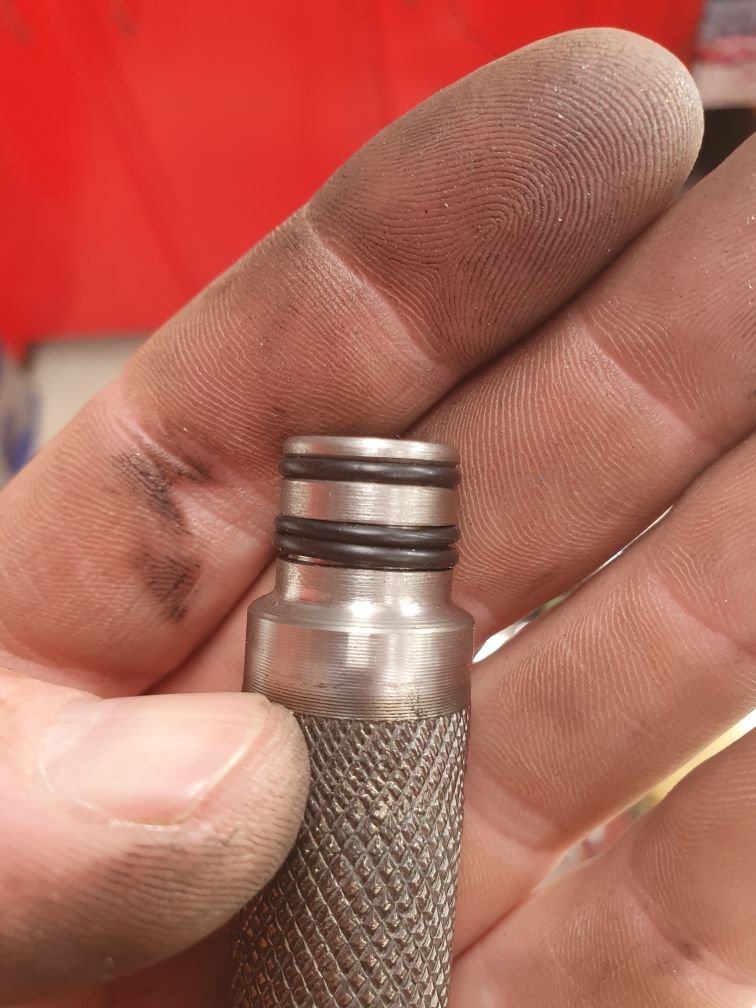
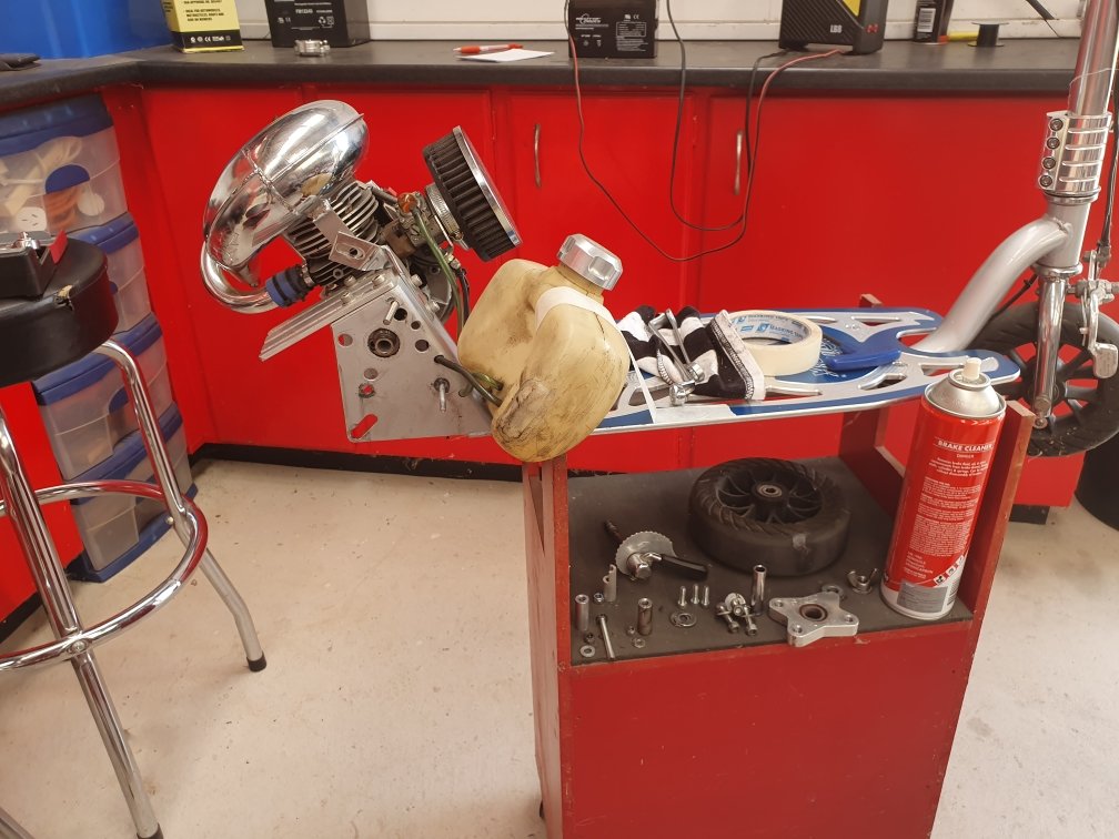
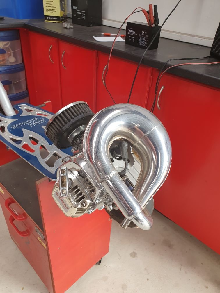
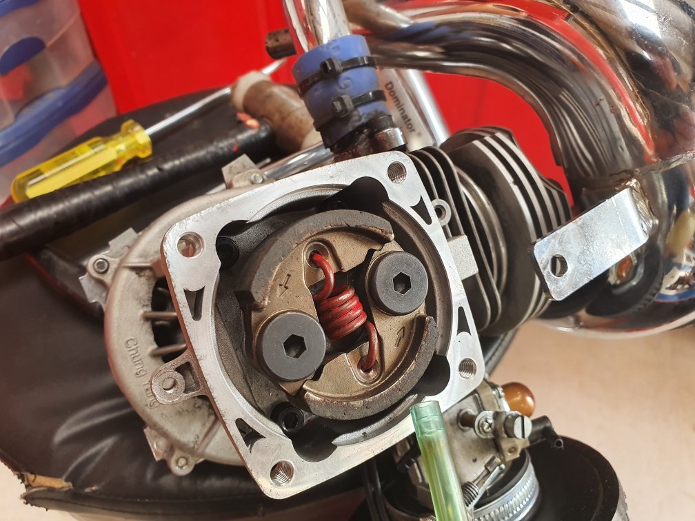
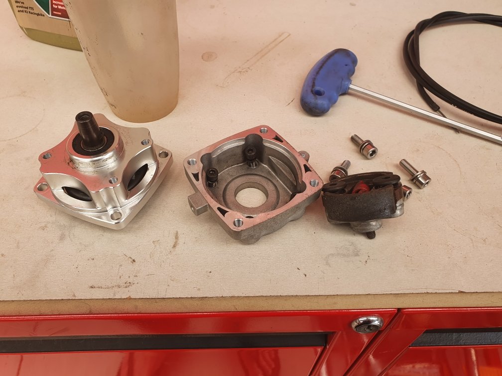
Added a clutch to a goped, so it's no longer direct drive. I can come to a stop and the engine can keep running, then go again. Normally gopeds are direct drive, so if the motor is running you have to be moving too. If you stop completely, then engine stops. Until now: This is something I've wanted to do for over 24 years ever since getting my first goped, but price and availability were always a bit of a barrier to achieve. Pictured are the clutch internainternals mounted in place. ADA make a kit that converts it to a 54mm clutch, and a cnc machined adapter that gets it to go back onto the frame with the right spacing. Sweet bit of gear, pretty high end stuff. I had to make my own spindle to convert it to take a 3rd bearing support, but it was a pretty easy job having done a few of them now. Weird lifetime goal to have...but i feel like I'm clocking life right now!
1 point
-
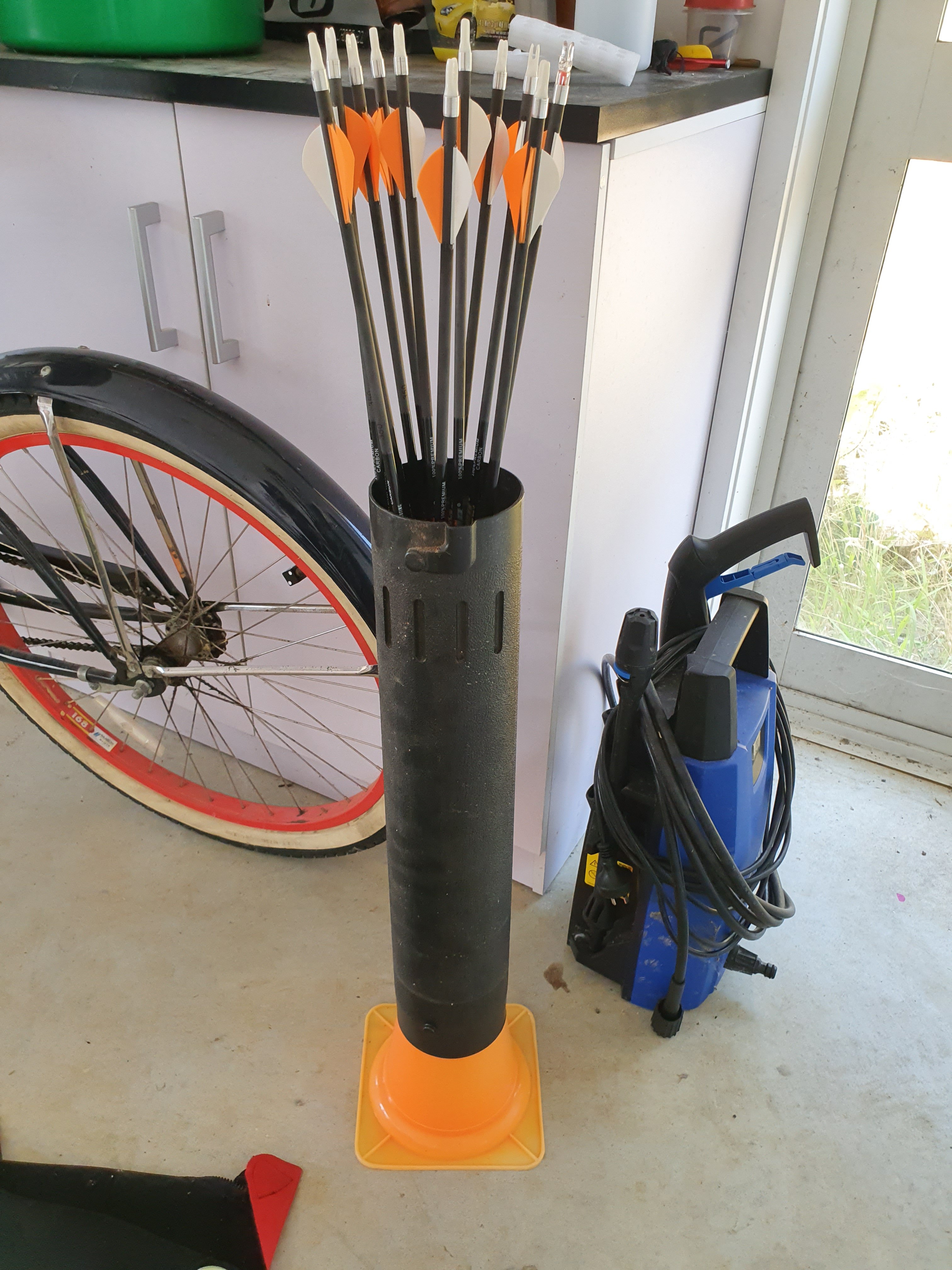
On a roll...arrow stand made from a sports cone and the vaccum tube from a leaf blower...
1 point
-
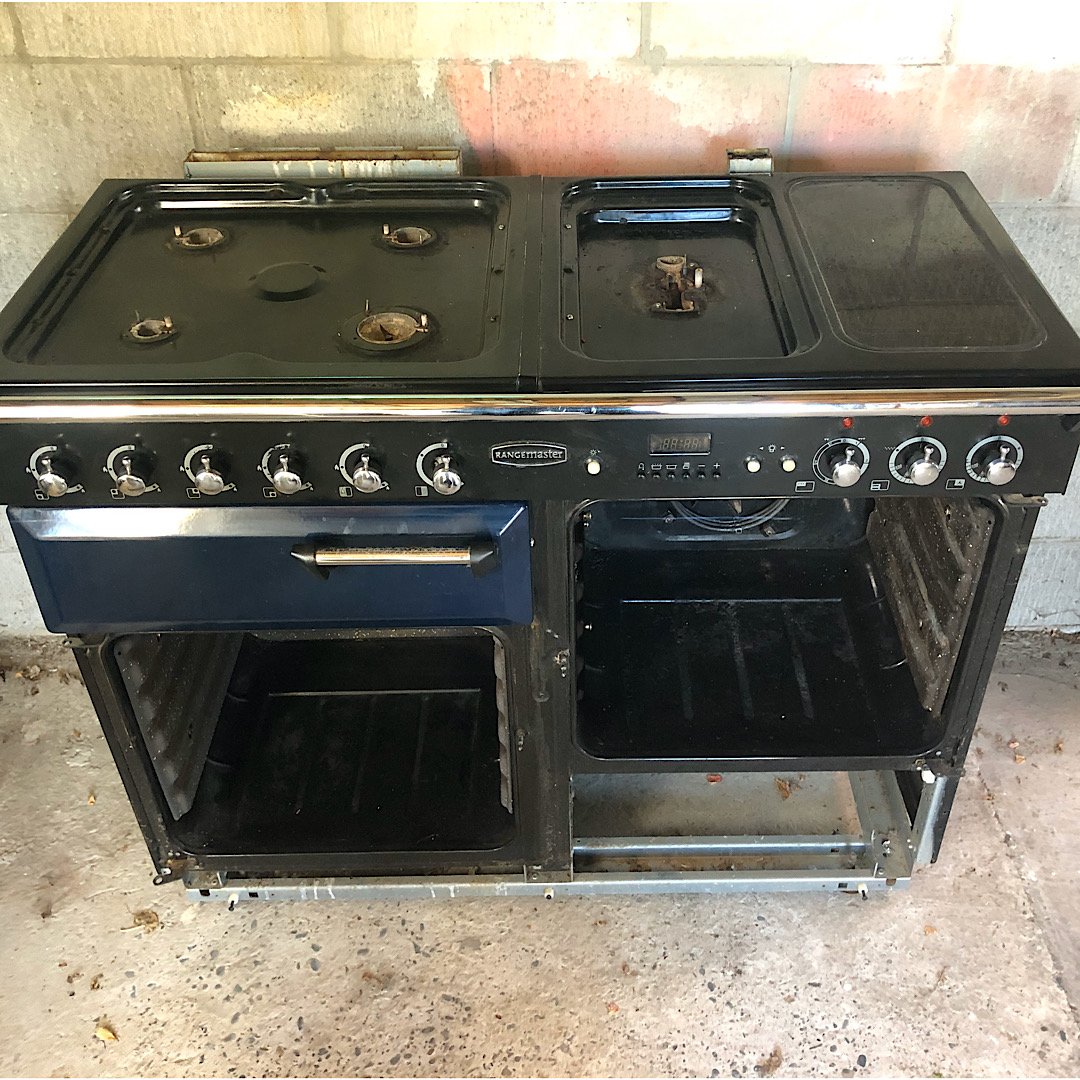
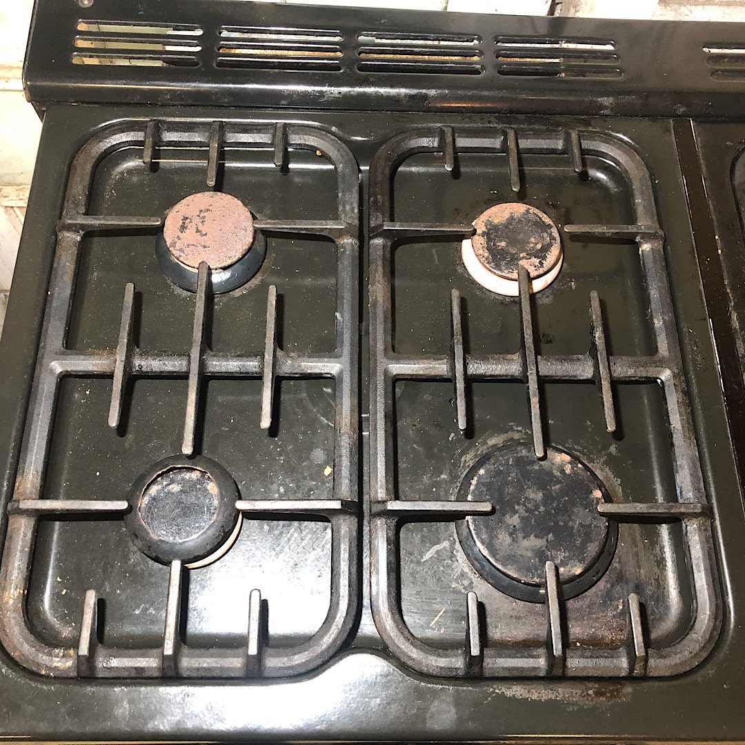
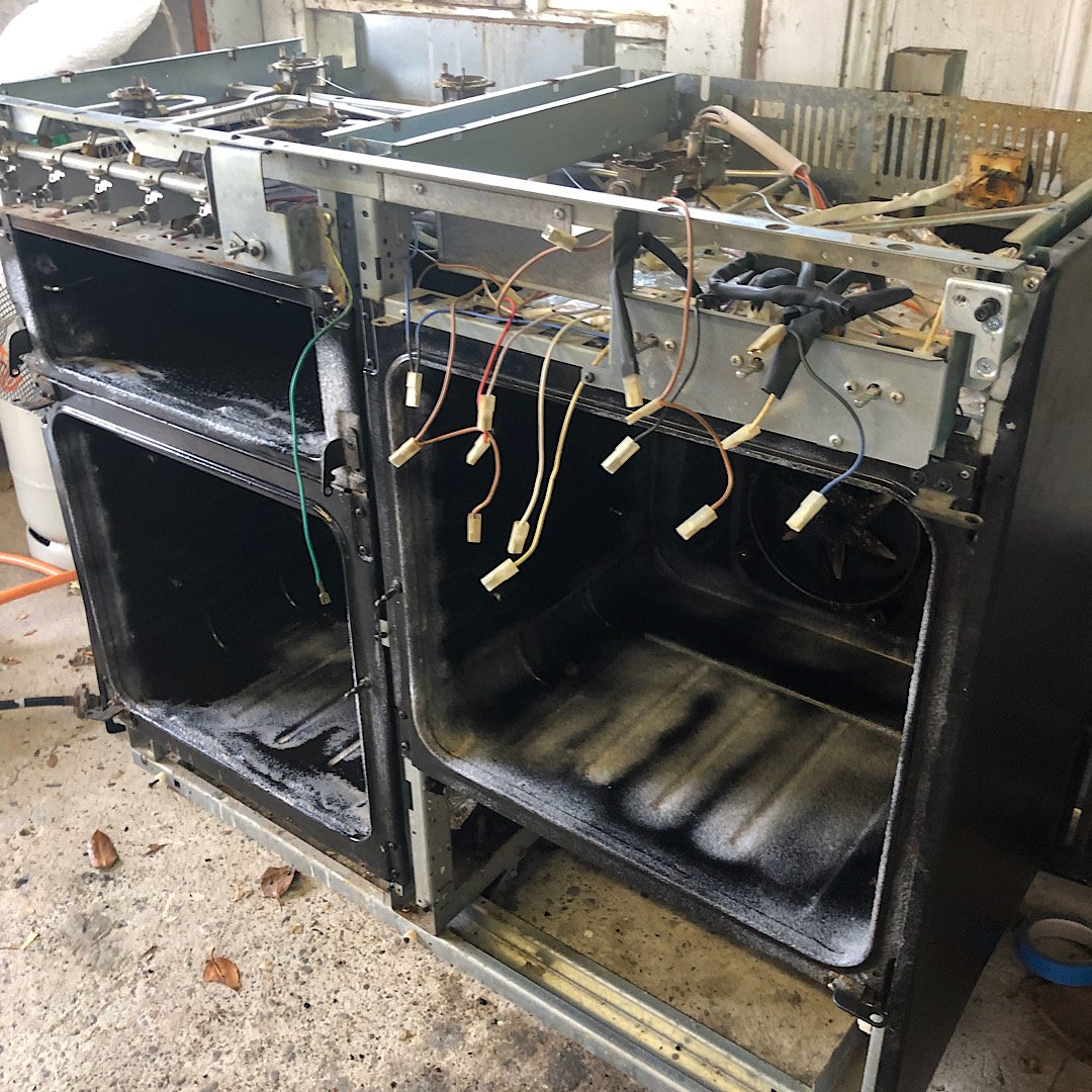
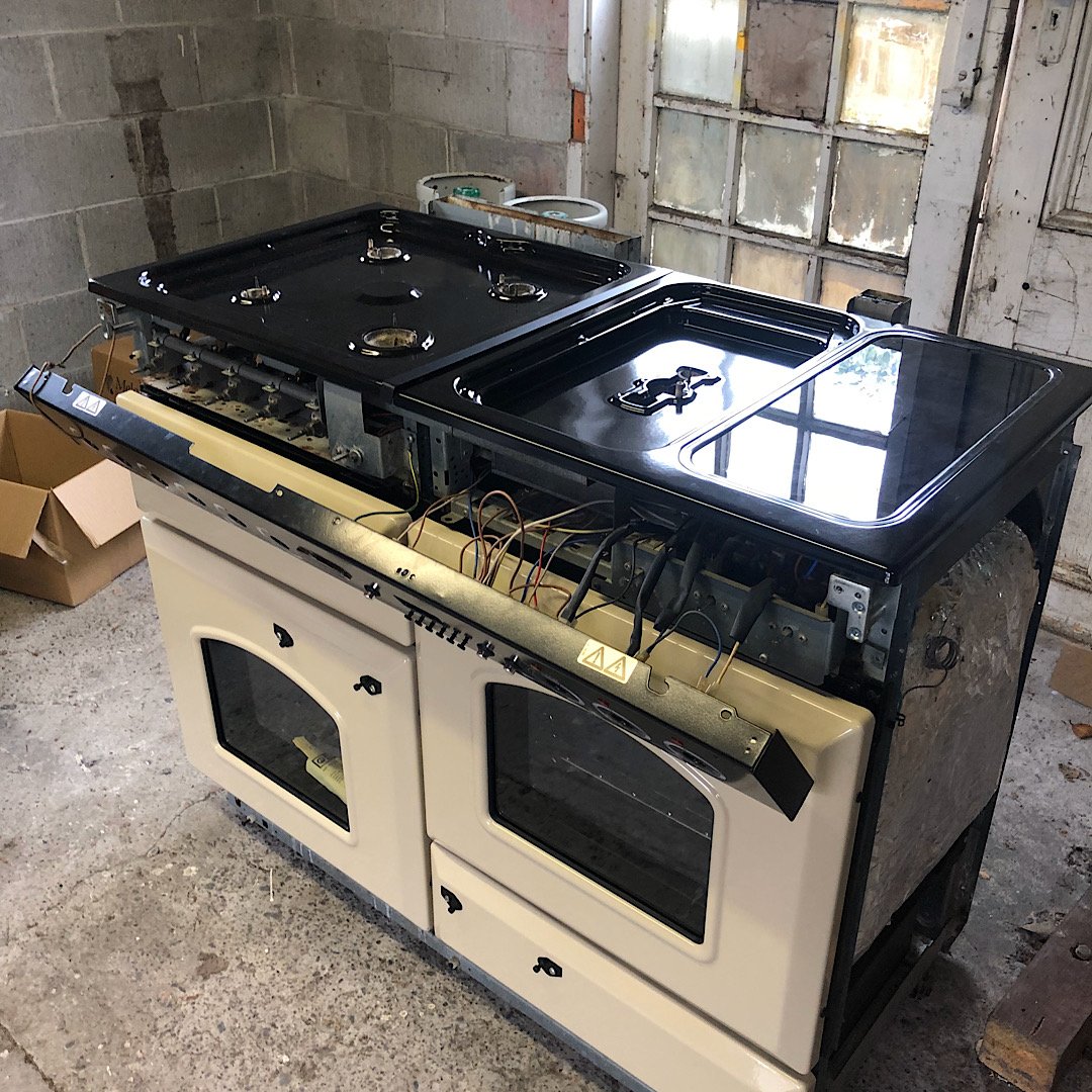
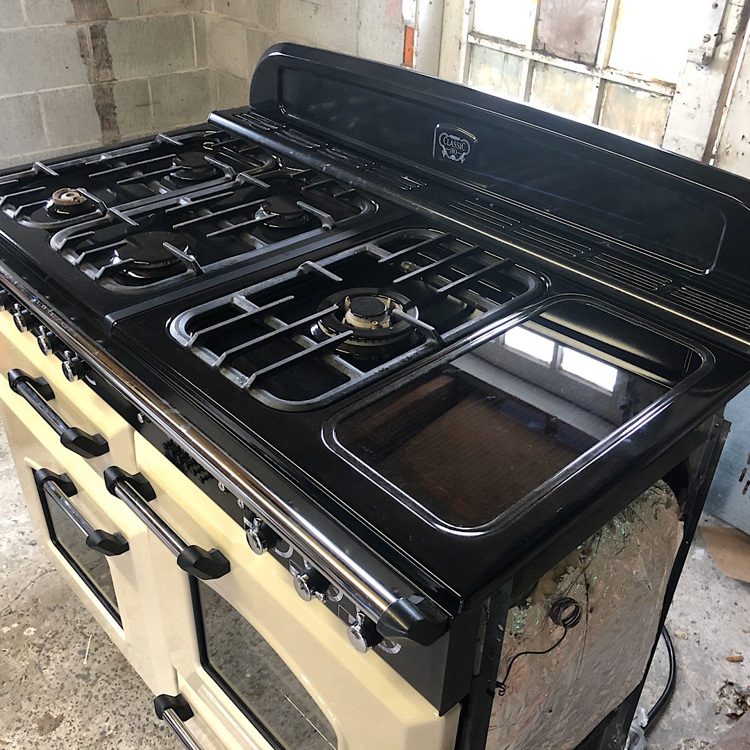
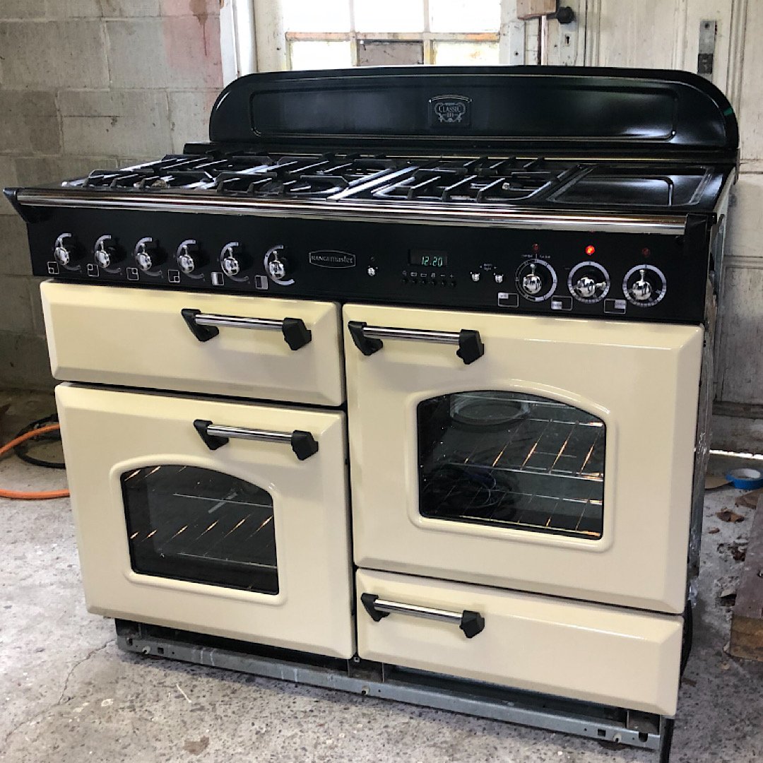
I wanted to upgrade our oven for the wife’s 30th, but there seems to be some kind of kitchen tax on nice ranges. I had no idea you could spend so much on a glorified indoor BBQ! So I got a ratty old one of Trademe that was supposedly a good brand and got stuck in. It was in a poor state, looked like it had never been cleaned a day in its life! I found most parts needed replacing and there were a few mouse nests inside... Friends and family were keen to help out which was great. After a few weeks of scrubbing and some parts hunting I could put it back together. I lucked out with a UK crowd that were dirt cheap on shipping and had most parts I needed. I had to get some bits locally, like some lengths of towel rails for the handles. It came out mint, and a fraction of the cost of a new one! Now I’ve just got to shoe horn it into our small kitchen!
1 point
-
1 point


.jpg.912bb3040822a564b02b2569c7cd2d47.jpg)


This leaderboard is set to Auckland/GMT+12:00