
Leaderboard


Popular Content
Showing content with the highest reputation on 09/12/19 in all areas
-
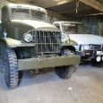
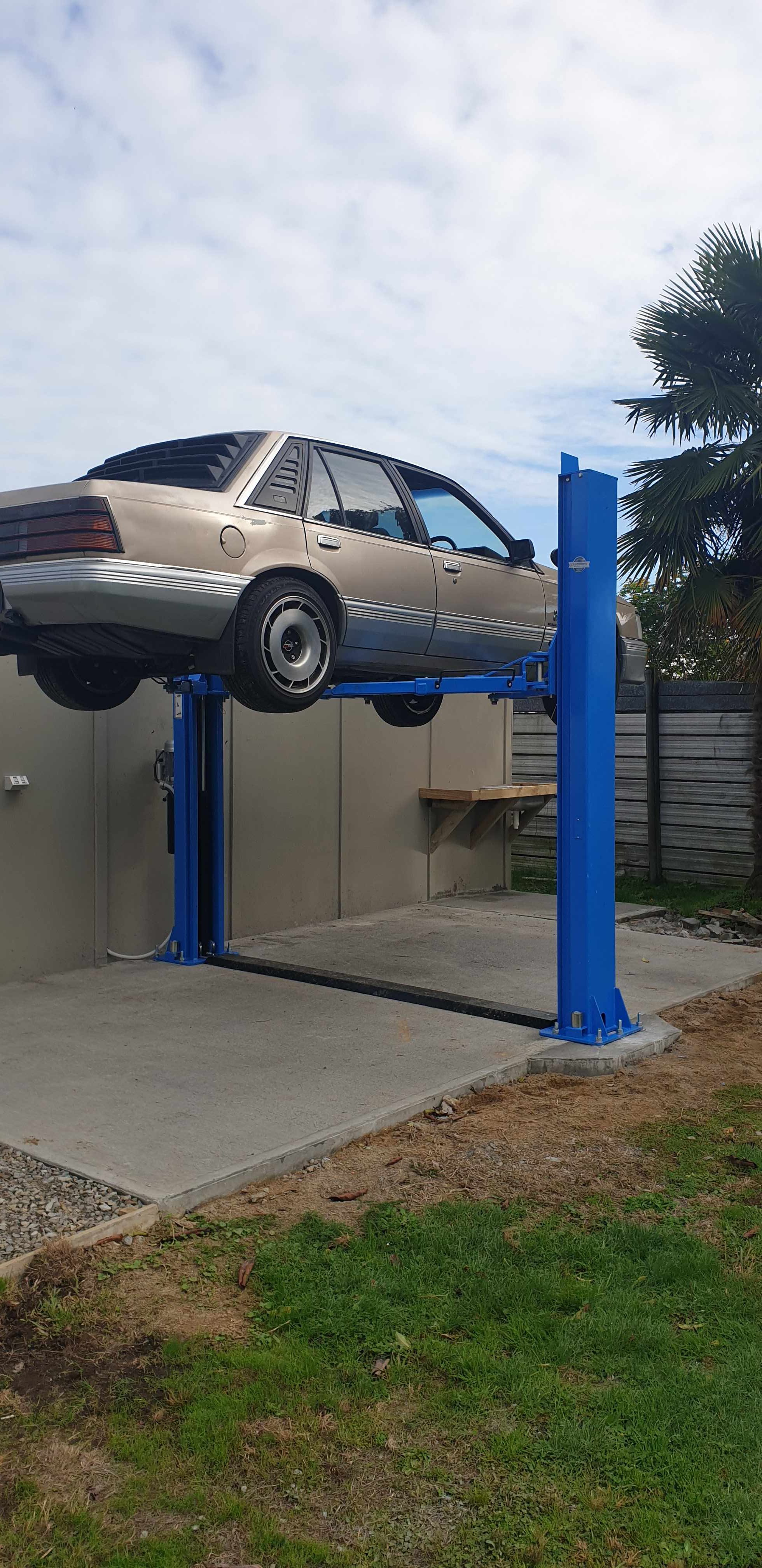
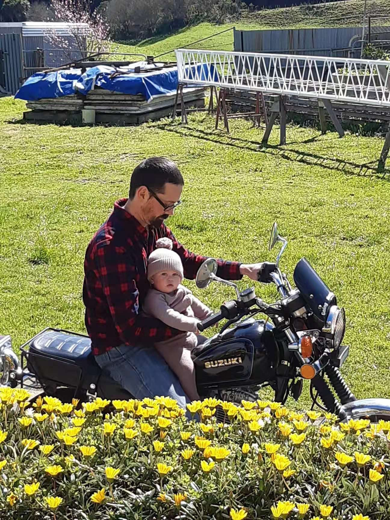
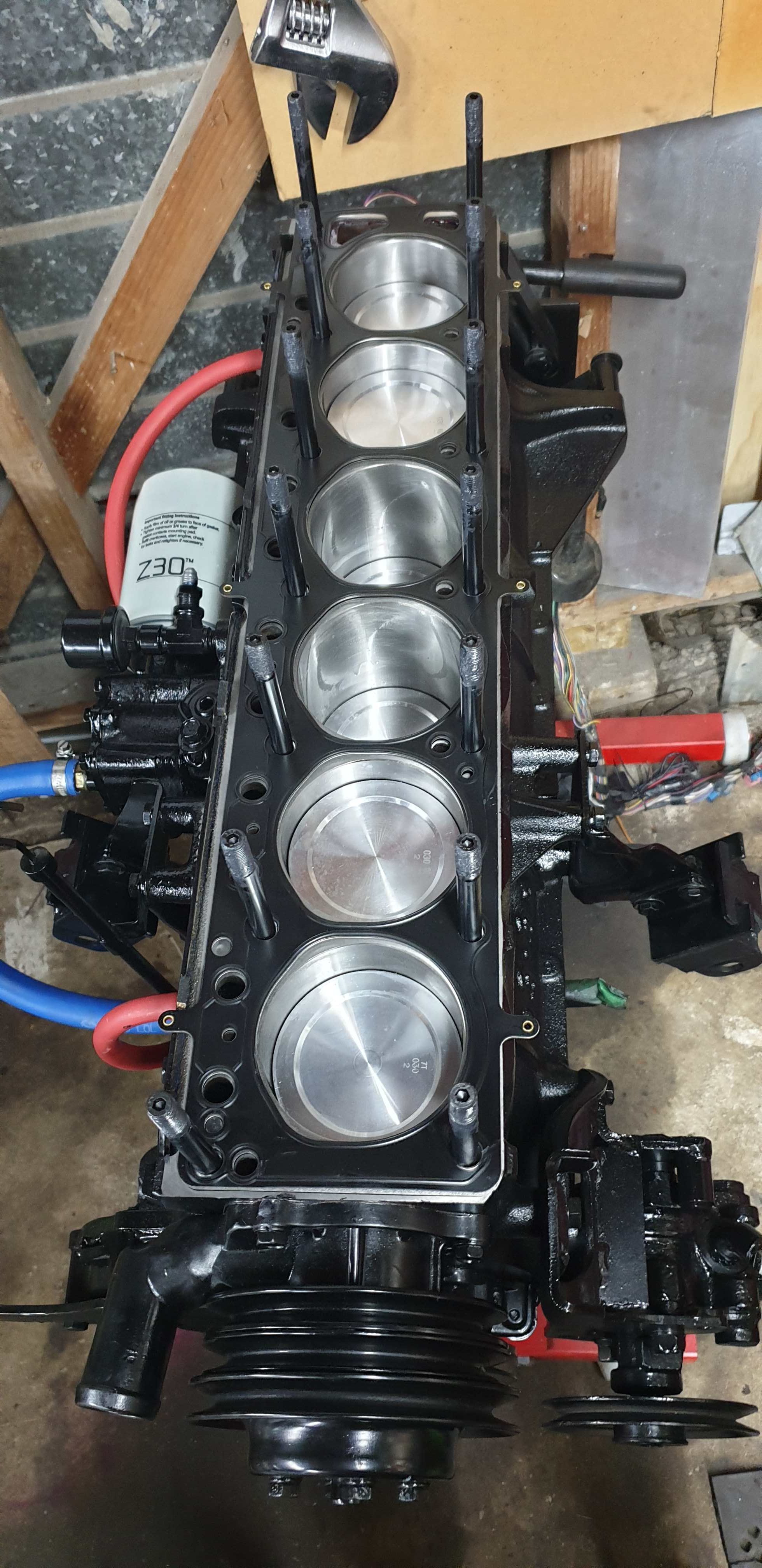
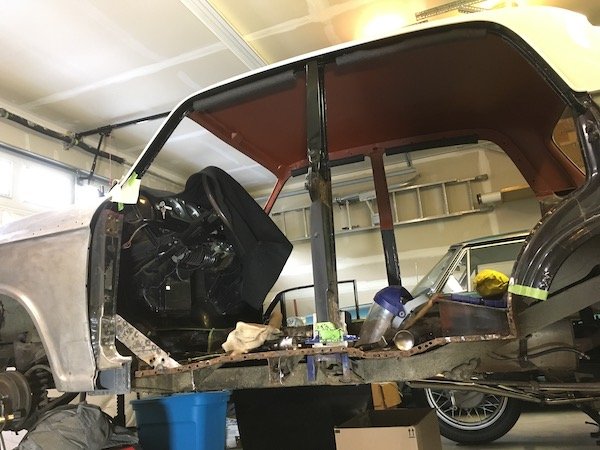
End of summer update.... Autumn's nearly here but the weather's still dry and the temp is in the high teens so I'll keep on using it until the winter rain and road salt arrive. It's been a good few months of Skyline driving, I've put quite a few hundred miles on it and am really happy I got my thumb out and sorted it for the road. No real problems except a continuing worry that the gearbox and diff are a bit low on oil. The plugs proved really hard to shift, at one point I had a set of 2 foot Stilsons with 2 foot of scaff tube and they still wouldn't shift. Finally today I got it on the 4 post ramp, stuffed a load of heat into them and got the bastards loose. Fucked them in the process and was glad/not glad that both g/box and diff were full of nice smelling, clean oil. Changed it anyway. They must just be worn out then. I'll let things develop. Started reshaping what was left of the bungs but then boss man Lee appeared with two shiny new gold anodised alloy plugs that are something trick for Land Rover axles or something, I zoned out TBH. Lighter than the originals so the car felt a bit faster on the way home. Pic for fred, hopefully more to come before it goes back in the shed till the spring.
 15 points
 -
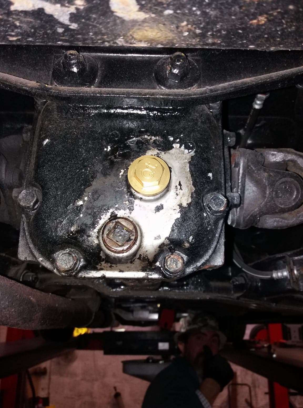
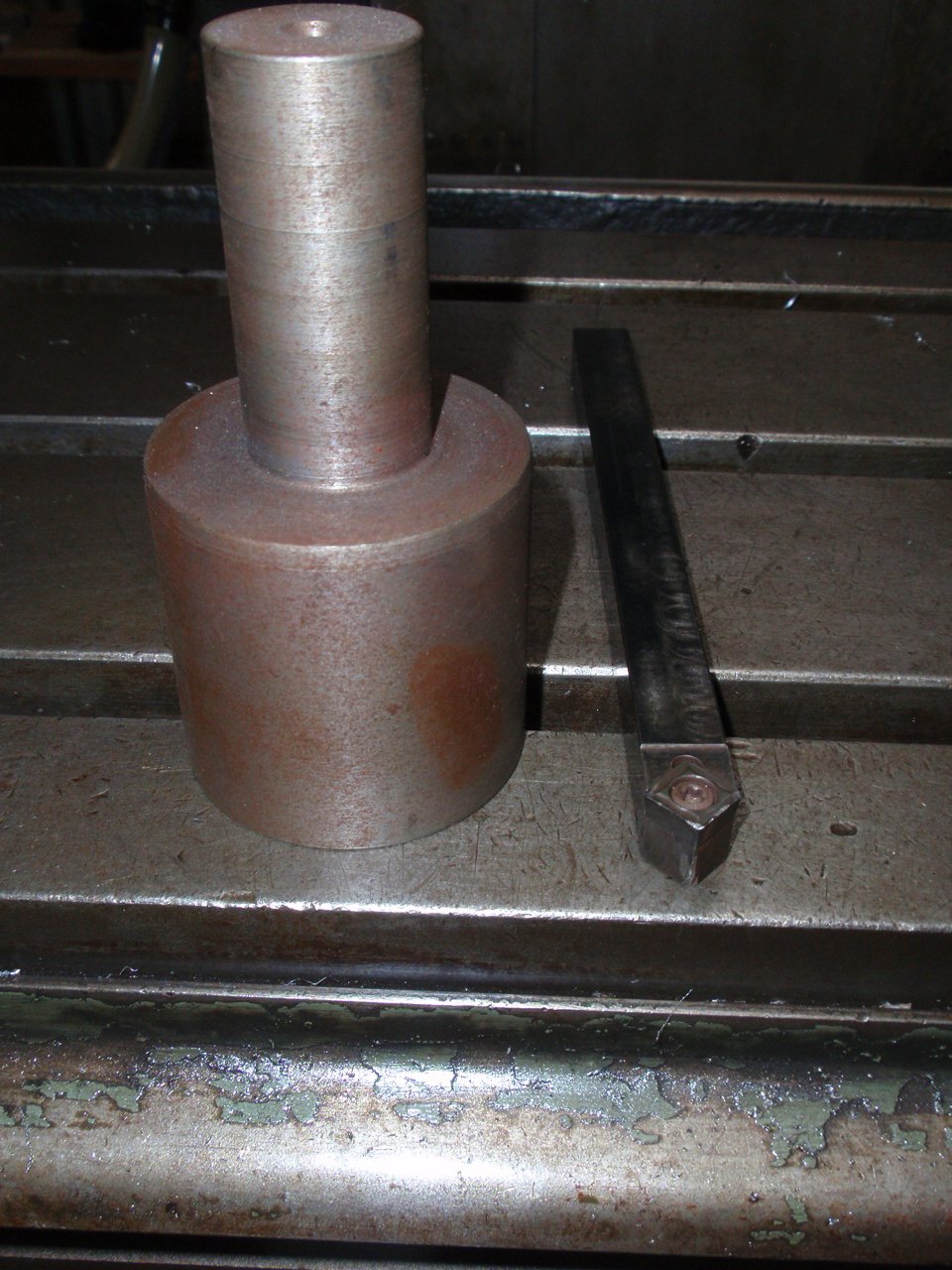
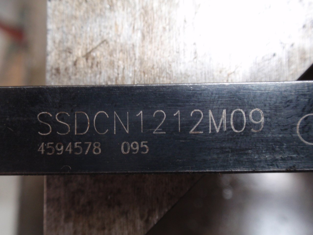
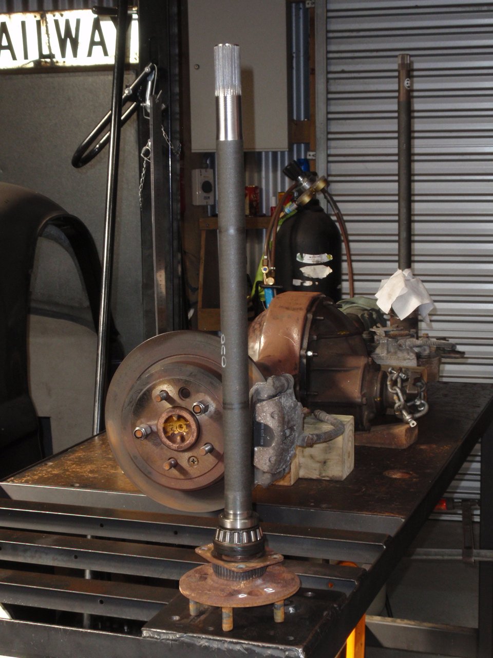
I am posting couple of pics so someone can have a look at them. Axle resplining stuff. BW78 Falcon axle shortened and resplined for use in the passenger side of an early 9". Disc brakes are the added bonus.
4 points
-
Little bit of progress on this thing, has been a bit of a one step forward two steps back type operation. Have taken this for a few test rides so far. Can confirm it goes hard for what it is. should try track down a go pro for some gnarly helmet cam footage and wind noise. Two problems have arisen since riding this thing; One, it is wayyyyy too rich. It is flooding the bike and wont start. I have adjusted the needle and running std main jet size, so the mid range and WOT feels okay, but it will not idle. The pilot jet is sadly mashed in there and seized, not even an ezy out could extract it. going to have to drill it out and tap the thread again, so need to track down a tap for the appropriate thread pitch. Then will smash std size pilot in and start tuning from scratch. Two, the clutch slips. Well, not really slips, but the disengage is very delayed, you change gear and about 5 seconds later the clutch releases and finds the intended gear. ugh, cases have to come apart again. So last night i pulled motor apart and the clutch plates looked okay, hard to tell if worn but they were pretty thin at 2.5mm. No worries i thought, i'll just swap the plates out from my low kms replacement motor. yeeeeea im probably gonna go ahead and not use those.... So this is where i am. now waiting for a clutch birthday parcel - springs and friction plates from Yambits. Bout a week turnaround for shipping. But i have made progress where it counts, with the installation of the world's most vital and MUST-HAVE ADV accessory - the Aliexpress dart pouch, the PPSC weapon of choice for securing your Winny Blues on long rides.4 points
-
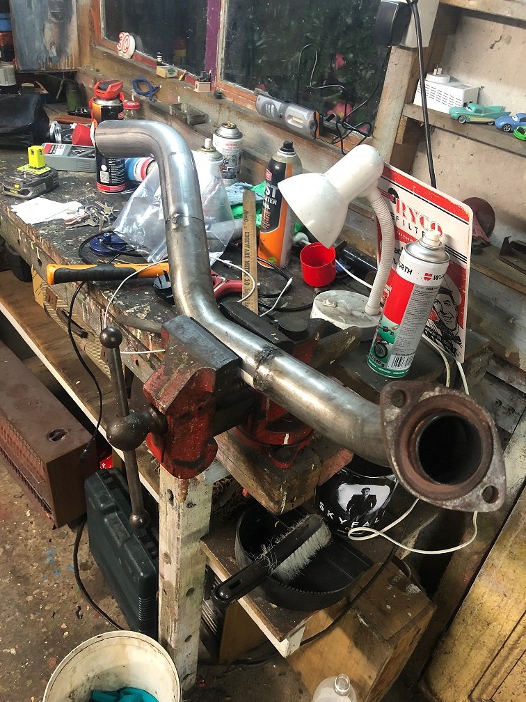
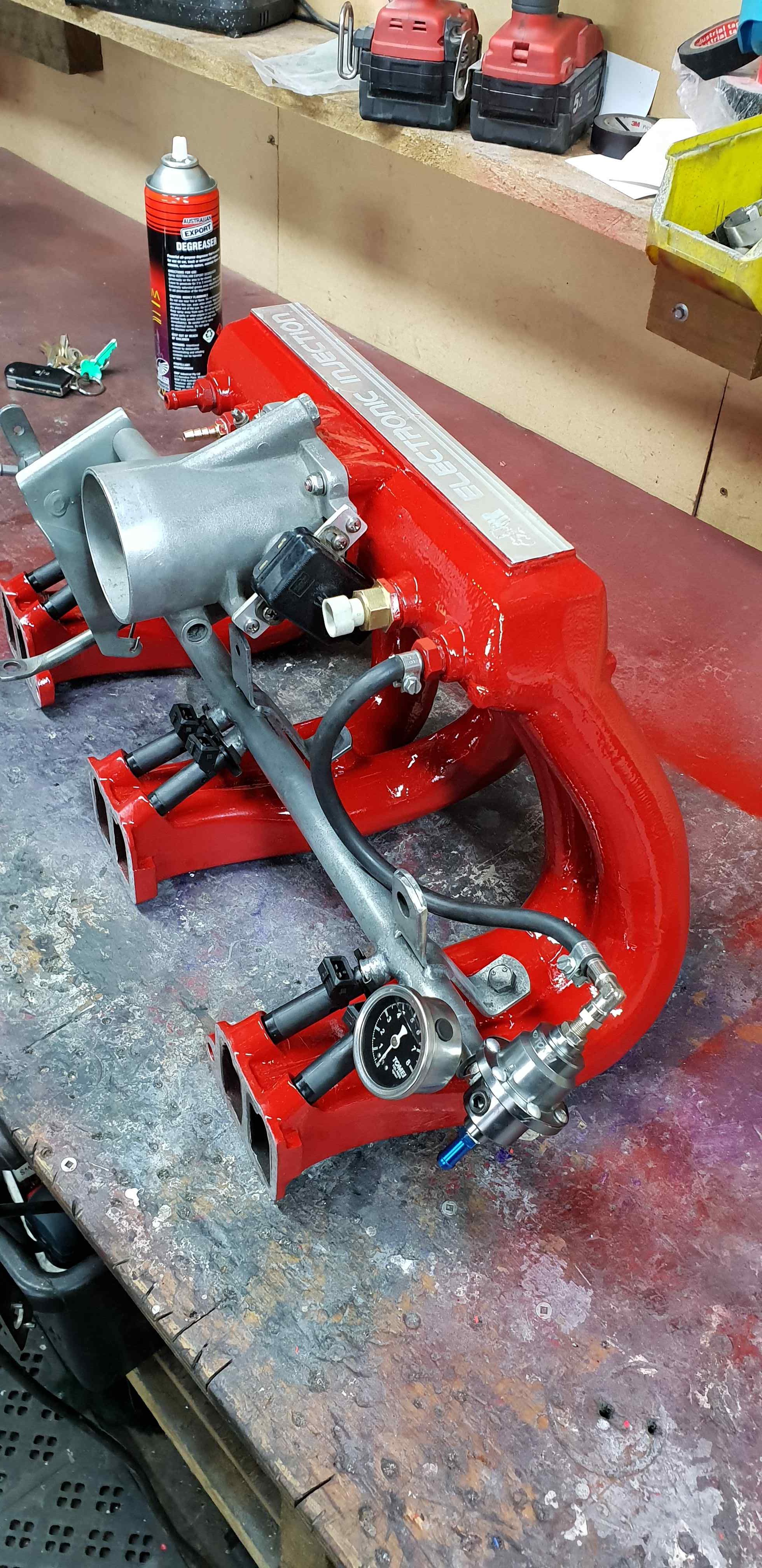
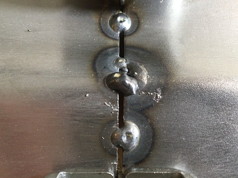
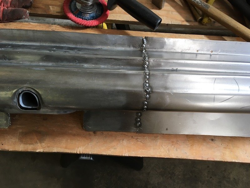
Another long stretch with no progress! I've been trying to find someone Id be happy with to run the exhaust, but as with most things on this build I've decided to give it a crack myself. I can only blame myself if it turns out bad. A big part of the motivation for this swap is the V8 sound, so I'm going to try 2 inch into 2.5 after the box with a decent muffler towards the back. I might change it around later if it doesn't sound right, definitely not keen on a high speed drone. Anyway here's the beginnings of my efforts.
4 points
-
Cheers Mate, yeah was bloody good to meet up. Dennis had an amazing time at Leadfoot, it was the first proper car event he'd been to in over 15 years and he yarned to heaps of people about the Spider which was really neat. He does still drive so it would be awesome to get him back in it, will hopefully be able to sort something out. Really looking forward to getting into this when i get back home, pulling the engine out and replacing the seals should be pretty straight forward and then it will be time to have a third driving session!4 points
-
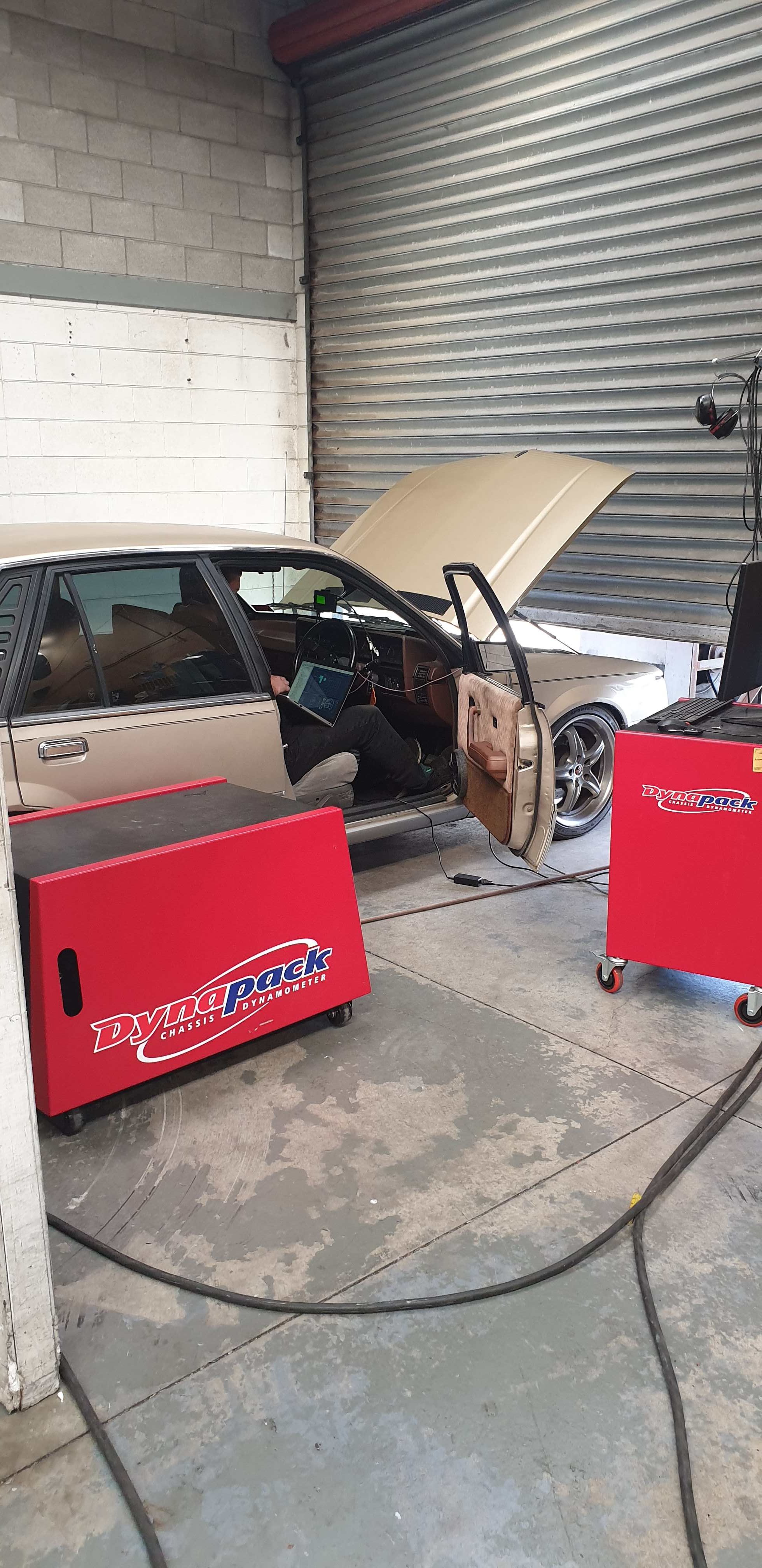
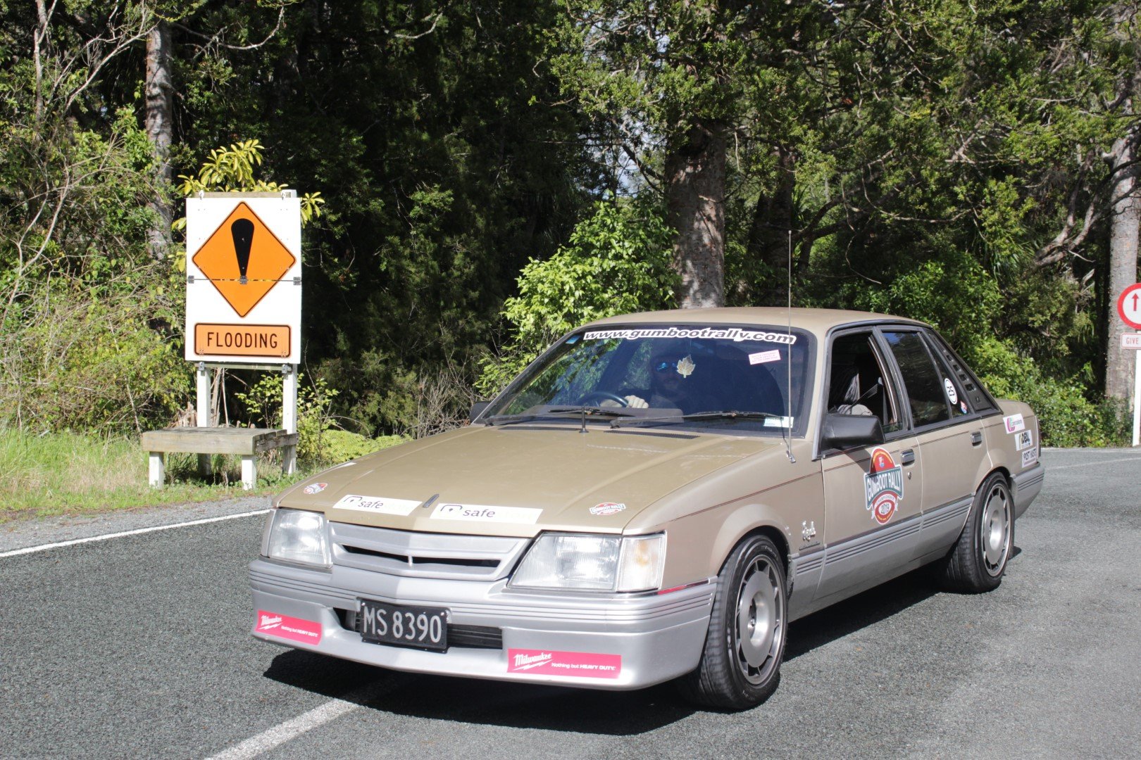
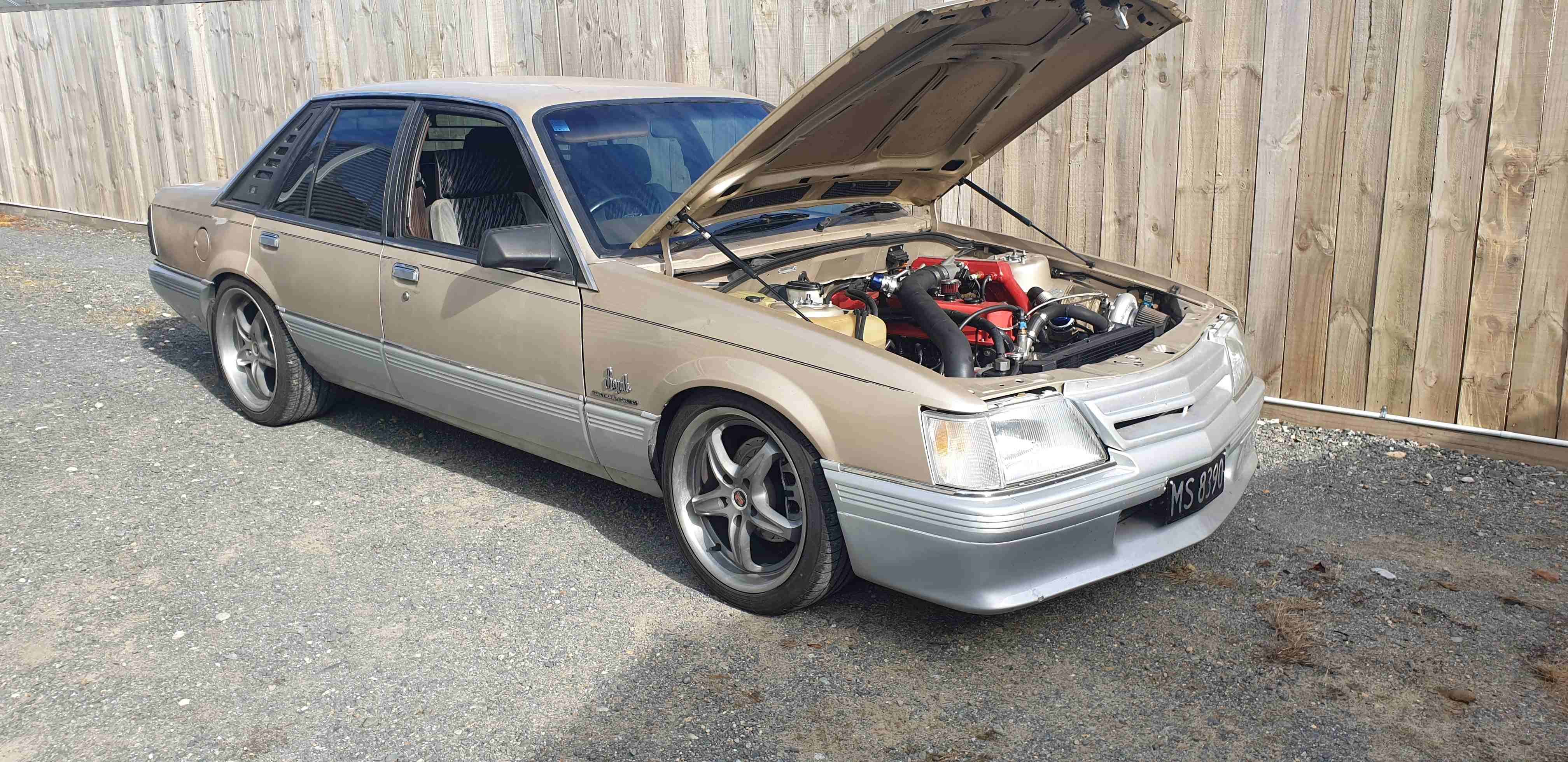
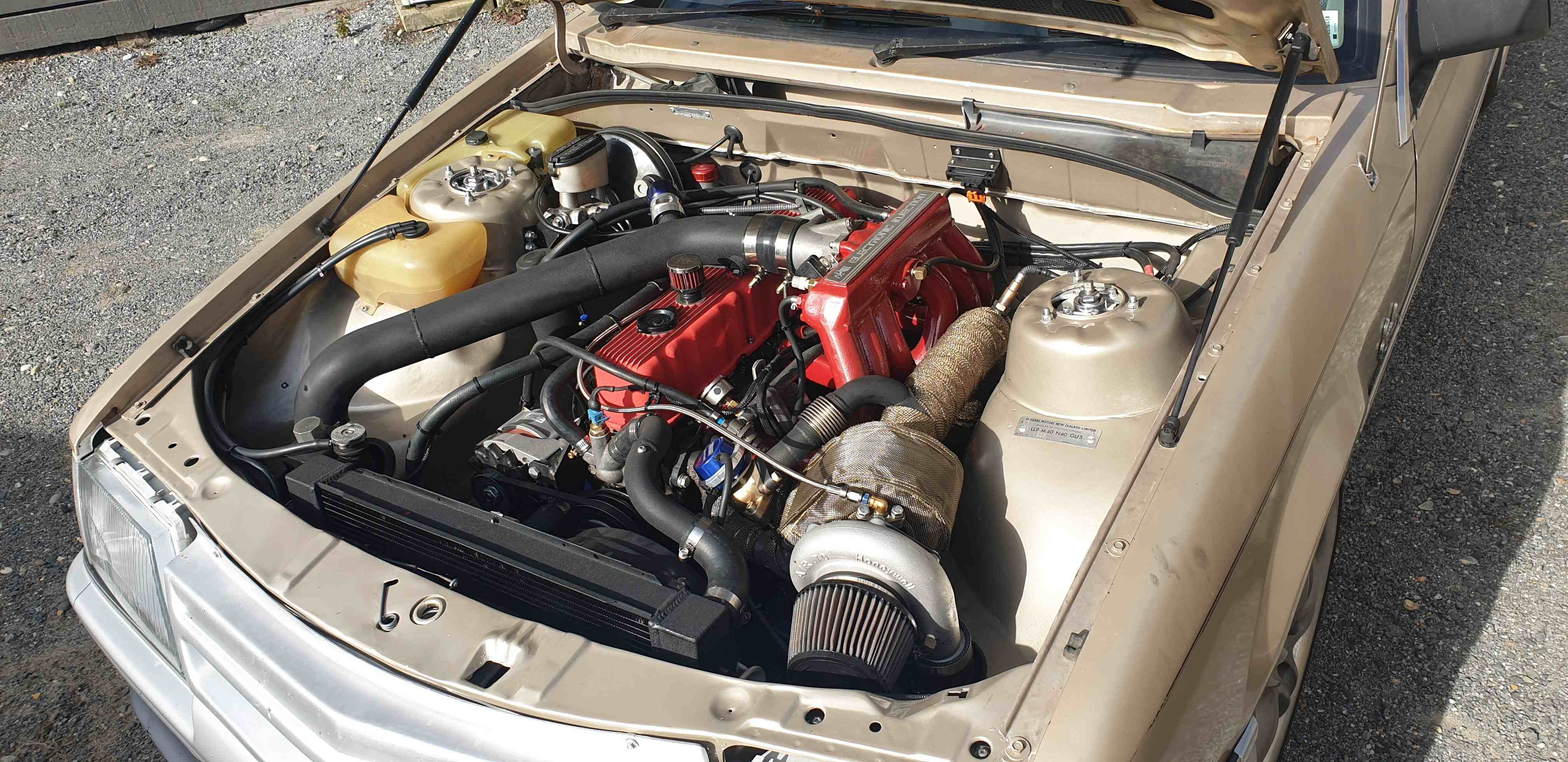
Passed clean sheet thru cert so stoked with that, brought myself a new toy so wish i had done it sooner. Took it up to Protune to chuck on the hub dyno... and my waste gate is too small, spiking 18psi of angry boost pixies at 3500rpm, aiming to run 7psi base with control up to 12psi to avoid splitting the crank from the block, ah well least the tune is now safe till i can fit up a larger gate. Oh also the camaro t5 gearbox i had fitted was stuffed so in a week had a commodore v6 t5 input shaft modified to fit, fabricated a new mount, bolted that up last wednesday and drove 1200km around northland for gumboot rally over the weekend, which Im super happy with how the car went, super responsive and torquey down low even with a low MAP/RPM limit, plus all the Spooley turbo noises
4 points
-
.3 points
-
Video of it almost running. Cannot seem to get the mixture quite right.3 points
-
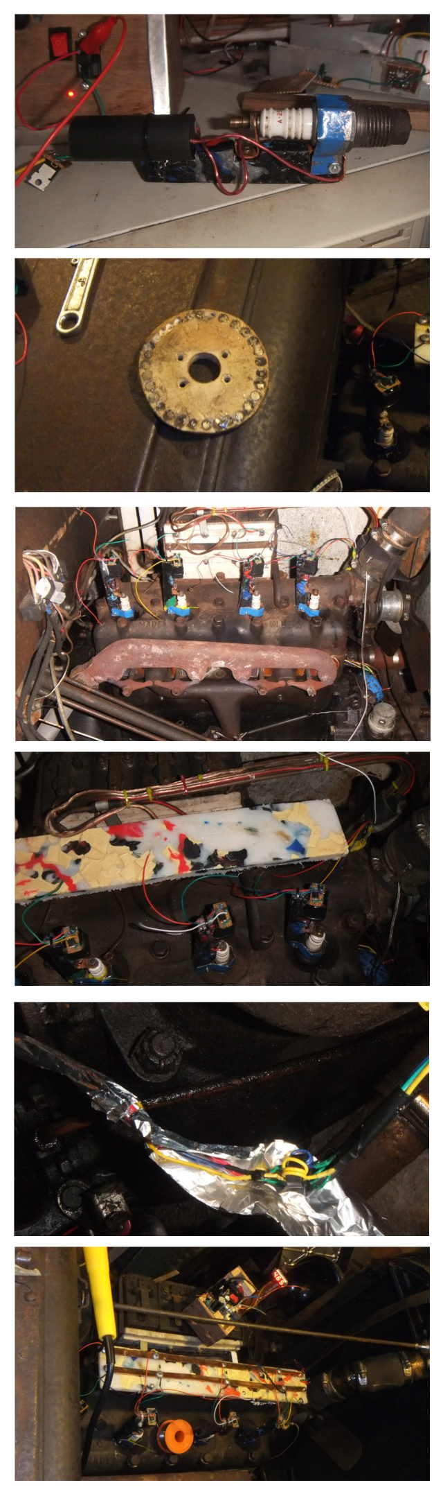
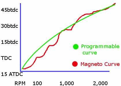
So i tried making my own coil on plug system with a piece of plywood with magnets glued in it in the front of the cam, an arduino pro mini with sensors mounted on the front of that, a sheet of plastic (Made from melted milk bottles & bottle caps) with copper screwed to it to distribute power i know those aren't proper ferrite toroids but thaat's just too bad. Wrapped in a tin foil tape to try & keep interference out (probably keeps it in?) The cool kids have MS paint graphs & stuff so i'll try be be cool too. The red curve is a rough approximation of how the standard magneto behaves. The green one could be programmed any way i like. If i put a high(er) compression overhead head valve head on it, then i can program a curve to take advantage of it. It'll also make old grumpy people sad. Most people just use a distributor conversion.
3 points
-
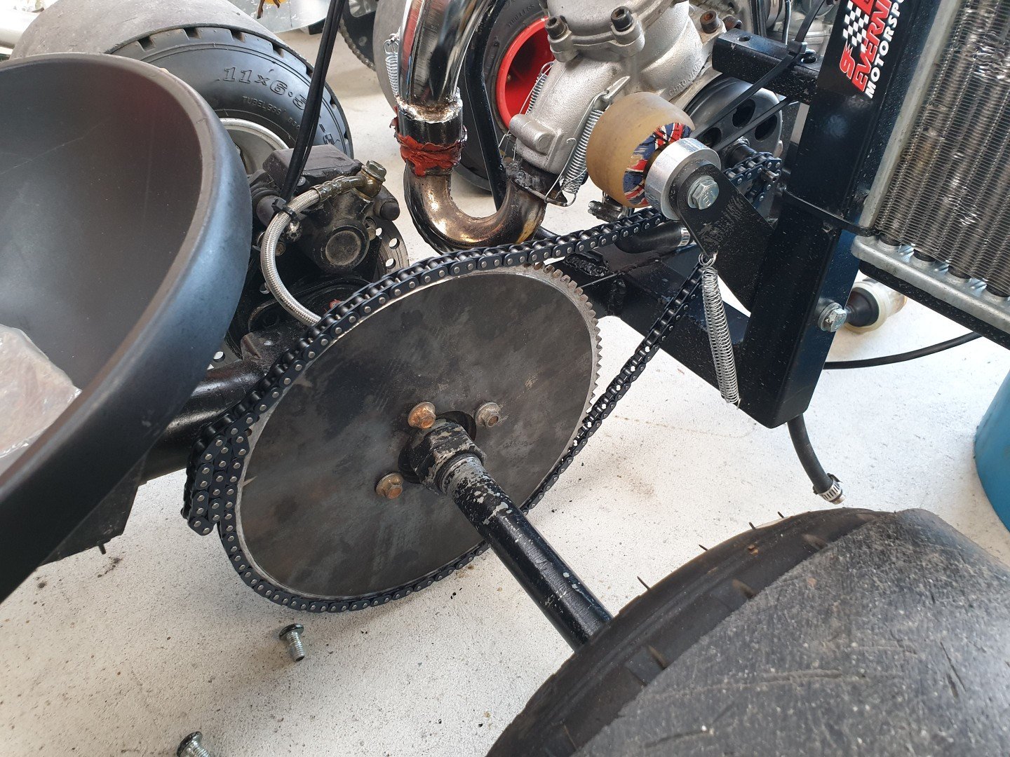
The Fxr motor is way wider than the Honda and the sprocket is nowhere close to lining up. Its sitting relativity centered in the frame so I don't want to try and move it over as I know I won't be able to get it square One option is to go for a wiiide Swingarm and wheel but that costs money. Why spend money when you can cut up a perfectly good motorbike. I chopped out the middle of the tube in the swing arm pivot so I could slide it up the frame. Looks like it'll work but this is the part I need a hand to get things centered and I square/a second opinion3 points
-
After you told me about this thread when we met in Blighty 2 weeks ago, I've finally sat down and read it. I wish I'd found it earlier. So cool. Top work on the sympathetic rebuild. It looks great. Also-So neat that Dennis went along to leadfoot with you. I could picture him having a great old time. Presuming he's still able to drive it is there any plan to find a location where he can do so? Fuck I love small cars, especially sports cars that handle well. This car is all that. Thanks for sharing.3 points
-
A car powered with 4 stunguns2 points
-
I have successfully made something that gives me 4 times as many shocks as a single ignition coil. Those sad old squares ignore me too.2 points
-
Do you think you have made a successful ignition system? I have noticed everyone on fordbarn is ignoring me now,2 points
-
Good to know. I was going to get a set for the lead as it needs new tyres after last year. I said i wouldn't but looks like i'm going to end up rolling 10 inch again2 points
-
Met the cousins
2 points
-
I did some work on the C50 today and it got too hard to figure out. I'll need a adult or someone with skills to give me ideas. I thought I'd strip the 139qma motors that @Raizer gave me both had been sitting and had water down them. Head and barrel off. New barrel ready to go on and fitted I ordered a 'racing' cam off Ali but when I measured it it had the same lift as the stock one. Must mean I got a racing motor right? I stripped both heads down. The g clamp worked well as a valve spring compressor The non egr head has much bigger ports so that's what I'll be using. I gave it a quick clean up and lapped the valves in. I'll give it a quick once over with the die grinder tomorrow to clean up the ports. I could splash out another 30 on a 'big valve' Ali head but that'll triple my investment2 points
-
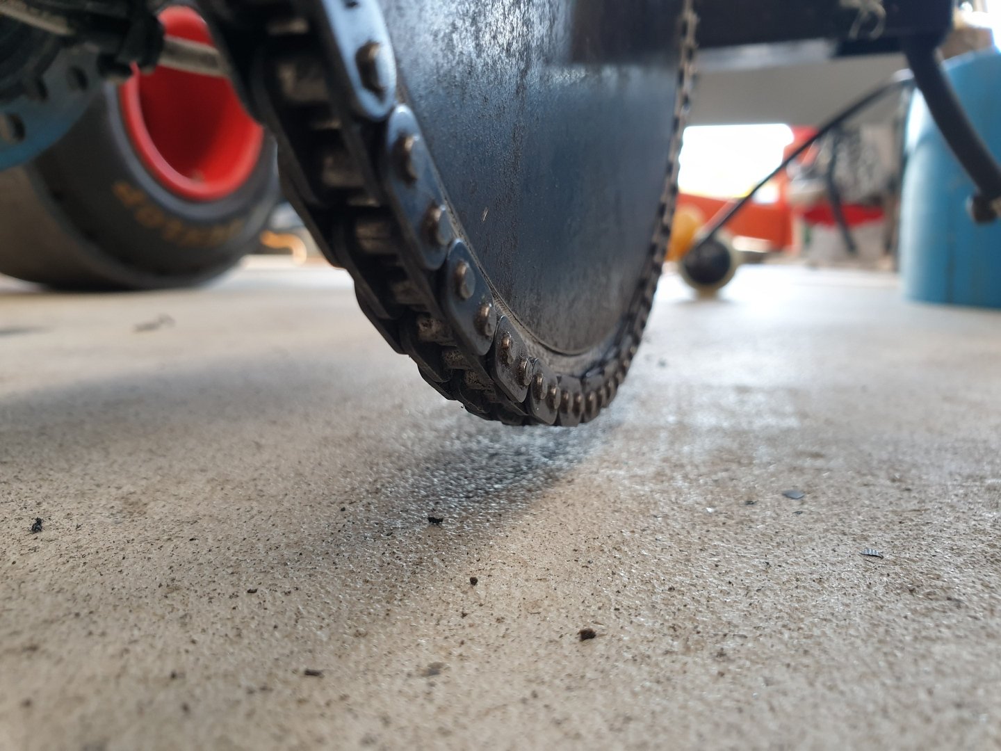
I chucked the new T8f sprocket in the lathe and took a 0.3mm skim off each side to bring it's thickness into spec. This was part of the deal when I ordered it. Here it is loosely mounted up. Luck of the Irish...everything clears where it needs too. Considering the first sprocket was almost half this size and that's what my design was tailored around - this was just dumb luck. But fuck it...I'll take dumb luck anyday, as I get my fair share of the opposite all to often. Ground clearance is tight, but it clears. I can put thicker sleeves on to raise it 10mm or so if this is really a problem? But think it'll work fine as is. Waiting on a chain breaker to arrive and then I'll sort the last steps out.
2 points
-
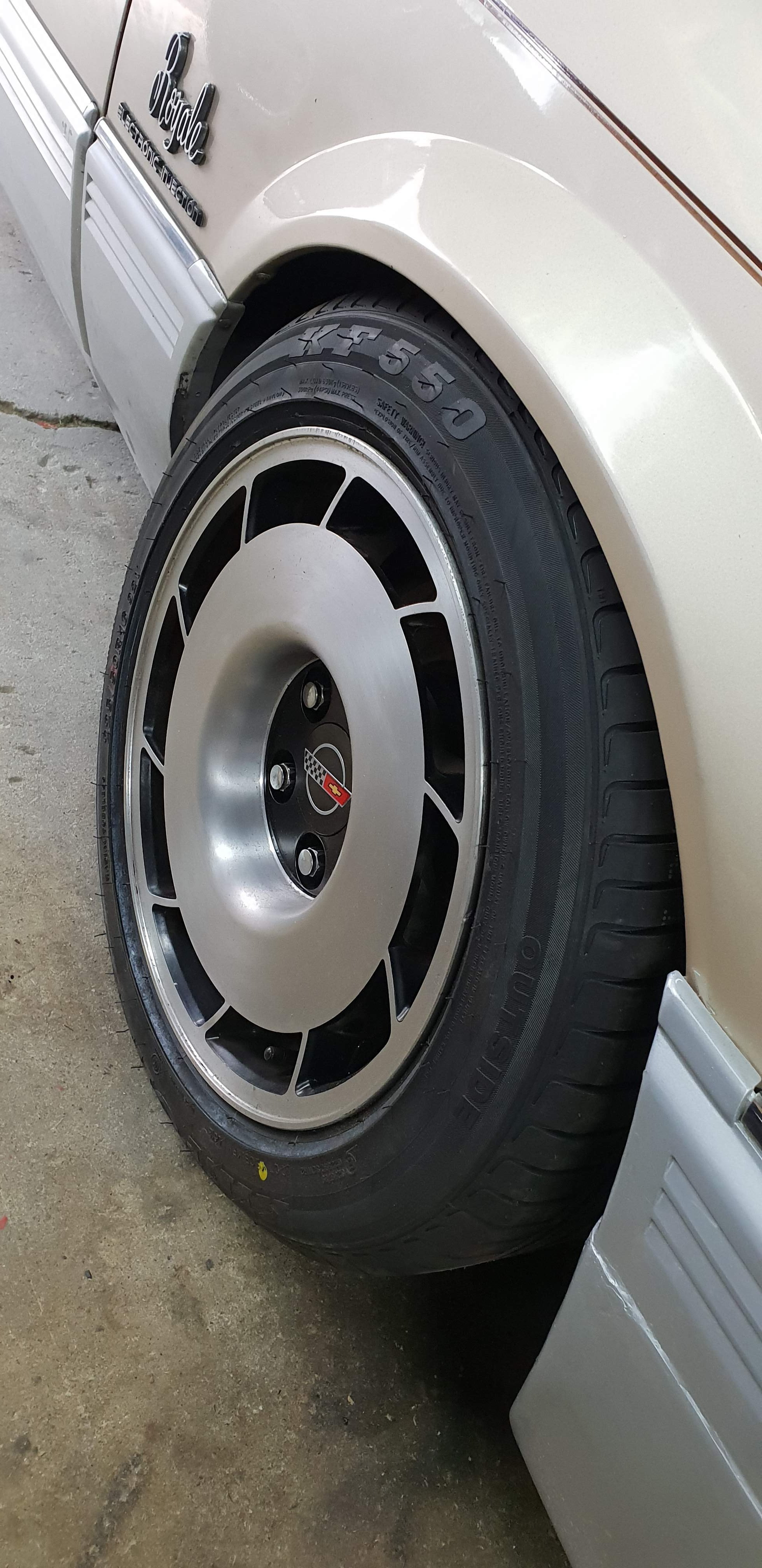
got it all pieced back together and running ready for Cert and a tune, also picked up a mint set of 16x8.5 &16x9.5 Vette wheels
2 points
-
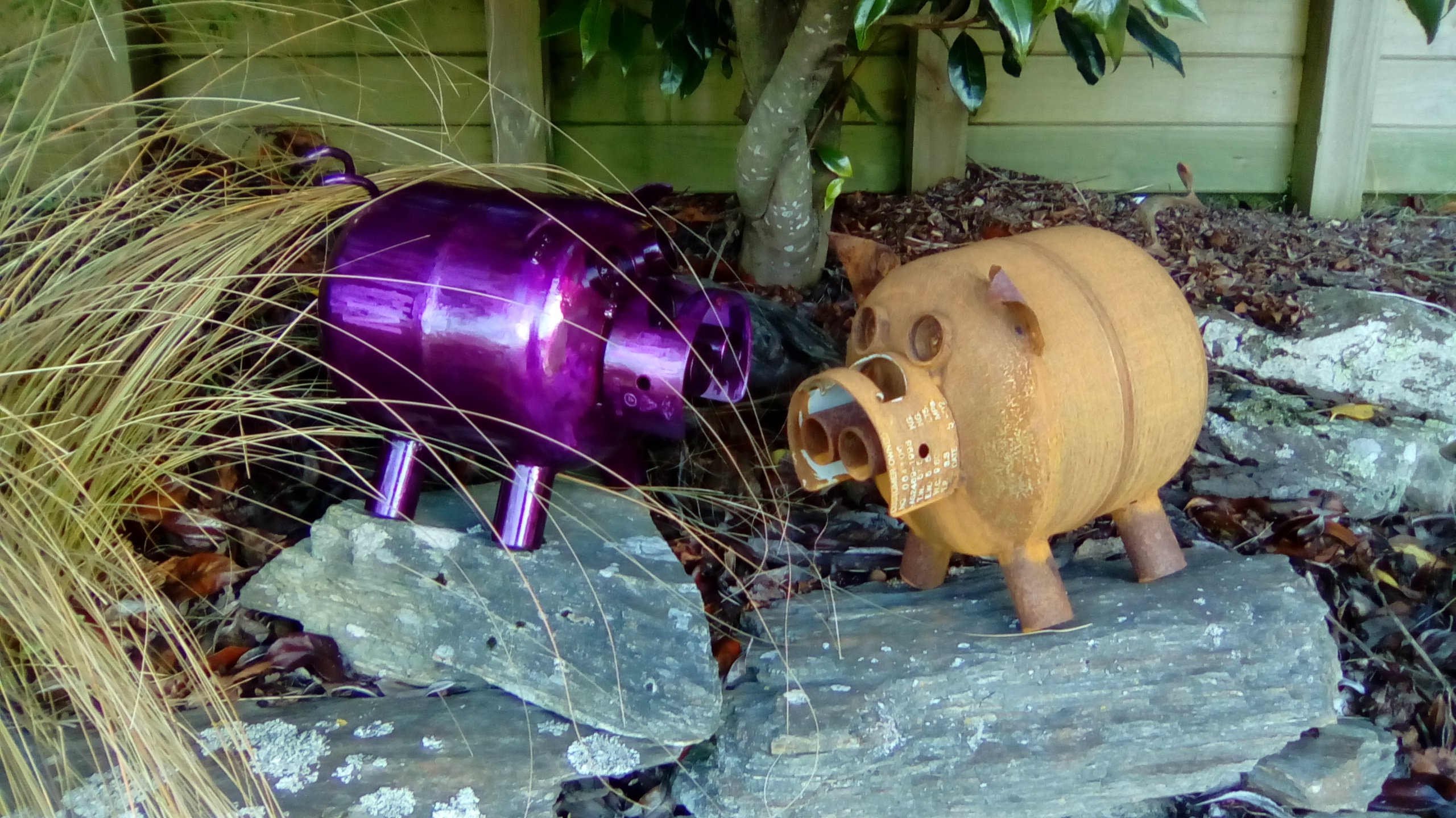
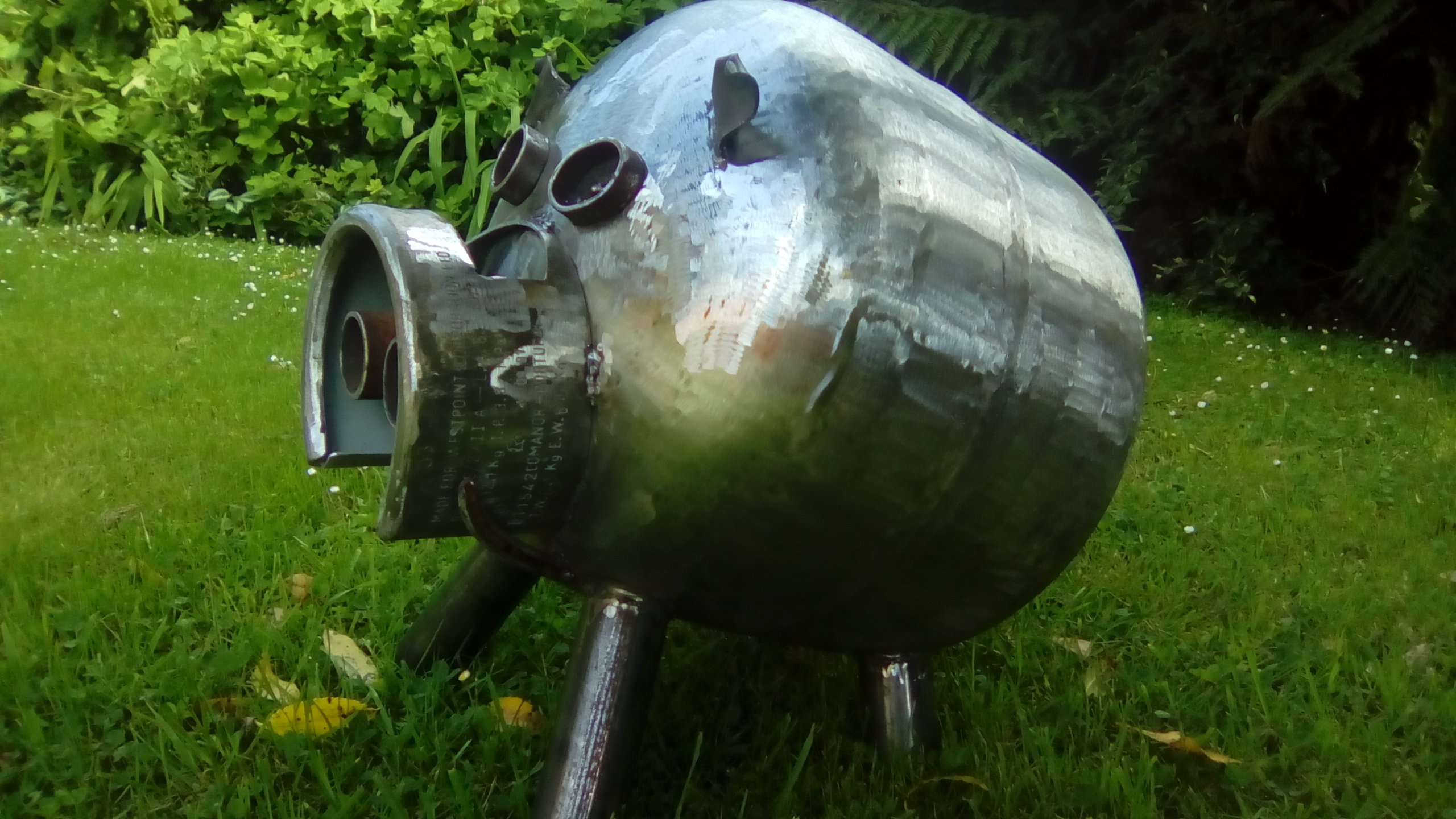
I just fill mine with water and leave them for a day. Empty them out and cut/ weld away. Some of my pigs. They are quite cool to watch as they weather. The rusty one took about 8 weeks to get a nice even coat.
2 points
-
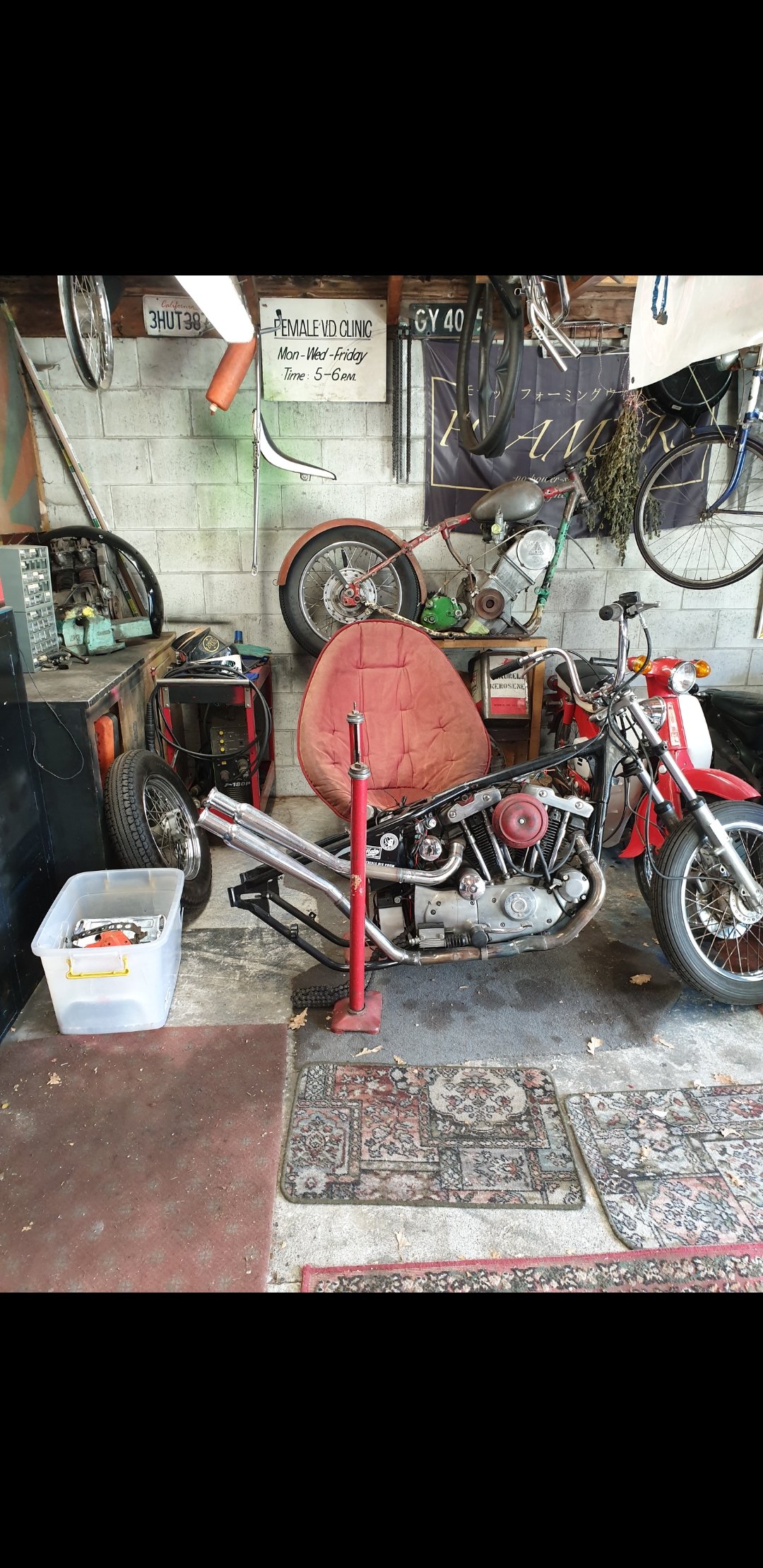
My oldest was super excited, he's done quite a bit on it over the last 2 years. Stoked to finally get it moving! There is still quite a bit to do before it's on the road, but the motivation is very helpful!2 points
-
Yeah the shafts are different but that is all. (Actually I am not 100% on the splines, just the housings) The bonus if you can graft it in is ditching the pesky UJs for CVs1 point
-
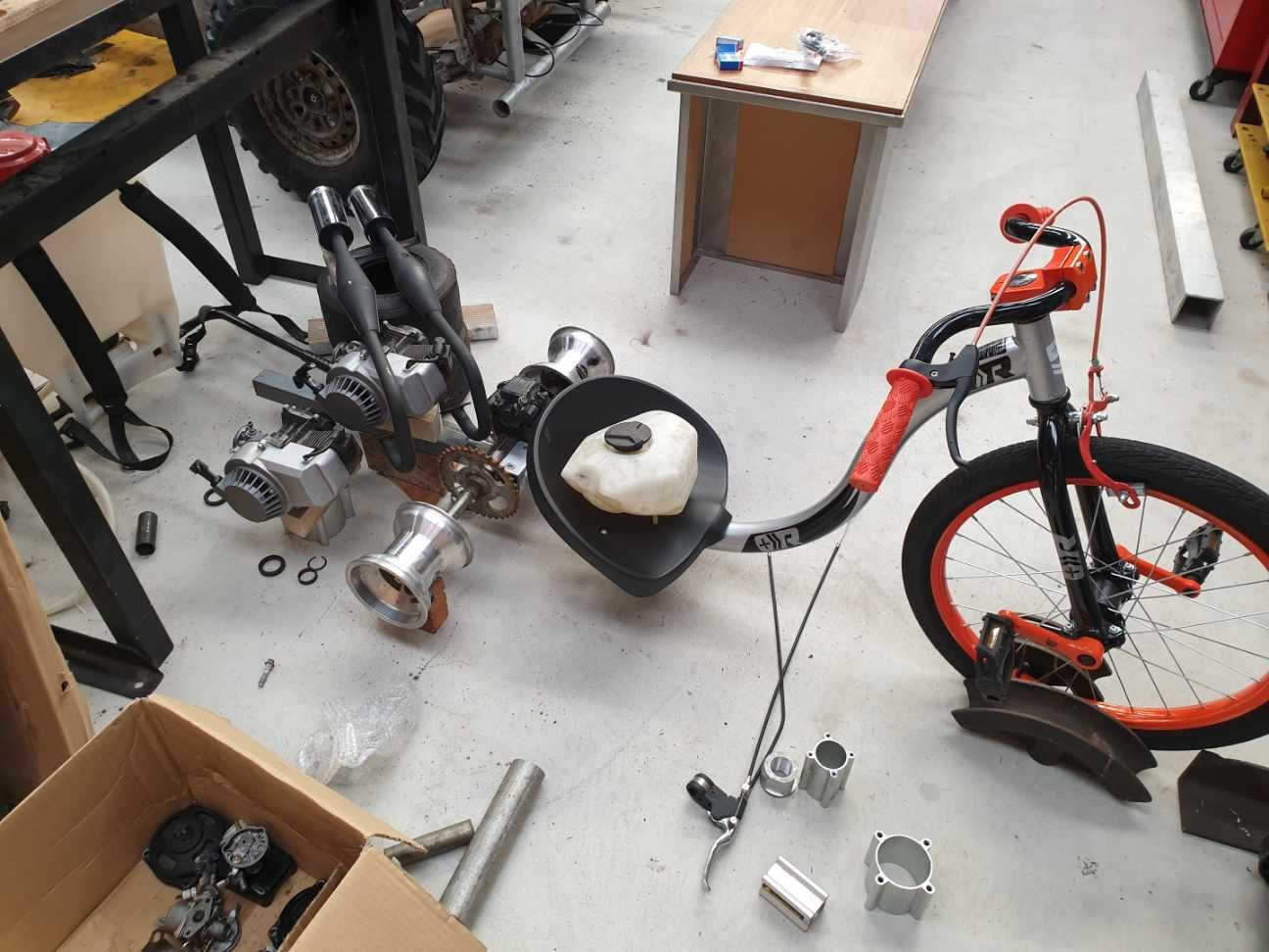
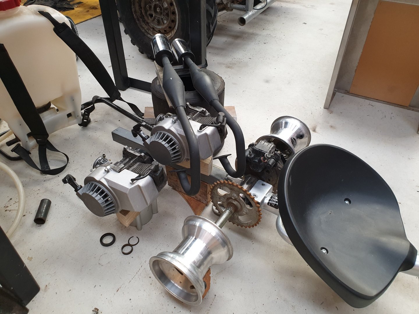
Okay, some progress... Mocking it up - will look similar to this. Yes that's right...and no you don't have double vision. Yup...twin motors...fuck yeah!!! Still lots to figure out and actually do in order to turn a collection of parts on the shed floor into a working trike, but progress is progress.
1 point
-
Check your clutch cable too, gummy ones can cause slow engagement. I had to do my restricted test with a sticky cable, made it interesting1 point
-
Yep you could chuck an aftermarket one on to double check pressure, the last one I did didn't make the gauge read any better. The one I service with 1,200,000kms takes a while to build pressure after a service, 5-10 seconds of looking underneath for the leak.1 point
-
1 point
-
Squint and it’s a Lambo1 point
-
But what if you want to make a backwards car?
1 point
-
engine cont.
1 point
-
Make seat base Wiring1 point
-
Who's got the dealz on SHINKO SR241 these days @MopedNZ? 18 inches tho1 point
-
Damn they look wounding!1 point
-
Resurrection Session 1: Missing sparks in cylinder number 6. Diagnosis = bad lead. Researched and found that VL Commodore RB motors have the right length. Not perfect, but close enough. Found bargain. Purchased. Fitted. Next went for a drive to diagnose further problems. Broke down. Pulled fuel line off crab and noted no fuel coming through. Luckily a strong and powerful rescue car turned up to help with a Jerry can that was rigged direct to the carburetor to return home. This worked fine until the Jerry can ran out. Ran the last 200 metres on brake-kleen sprayed directly into the carb whilst perched on the guard. Diagnosed fuel blockage in tank and now dead electric pump. Cleaned out tank and gave it a paint. Will now try sourcing a new pump and nylon lines.1 point
-
Can you fail wof if you've just cut out the rust, so no more rust, it's just a nice cleanly cut hole1 point
-
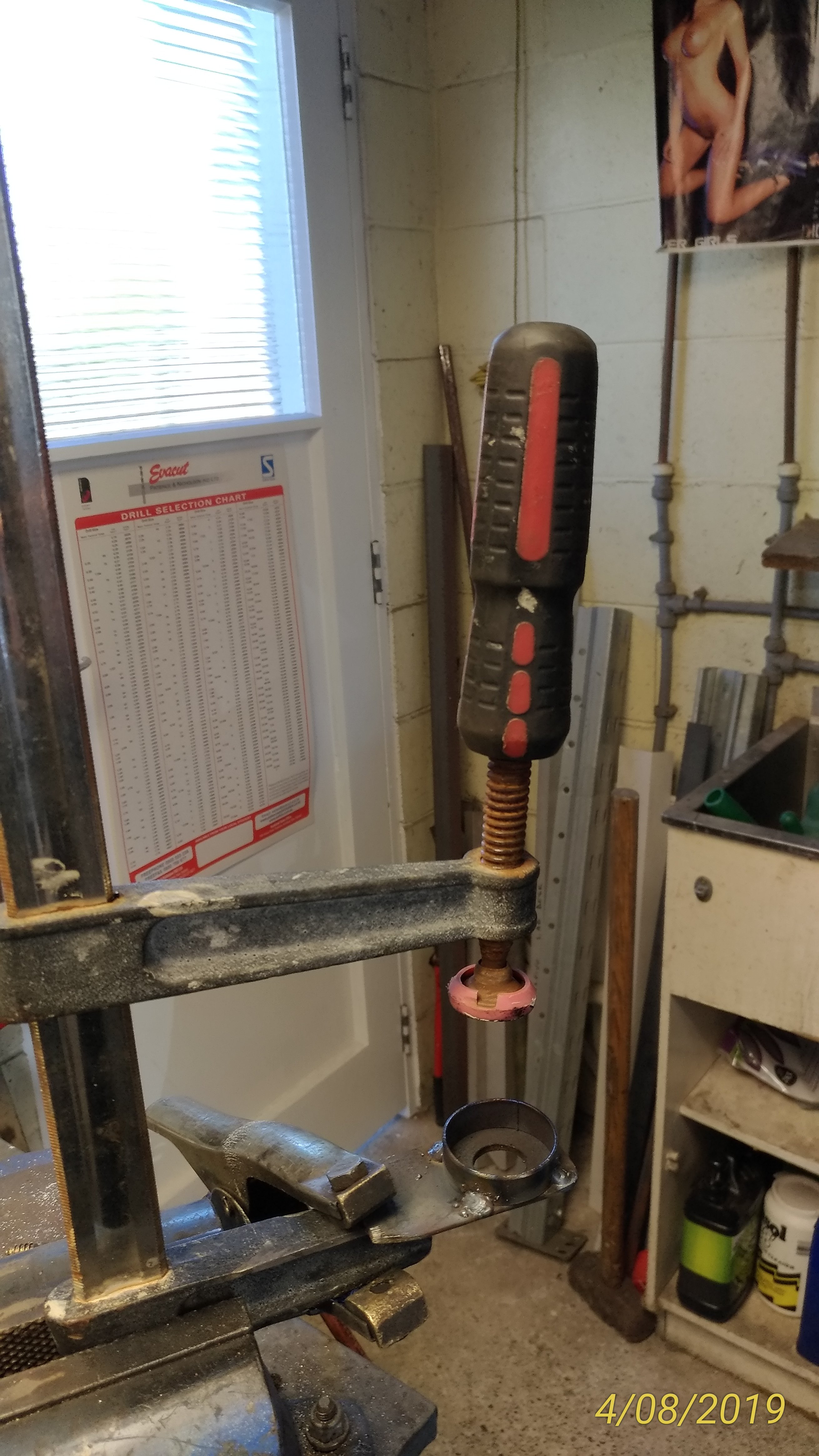
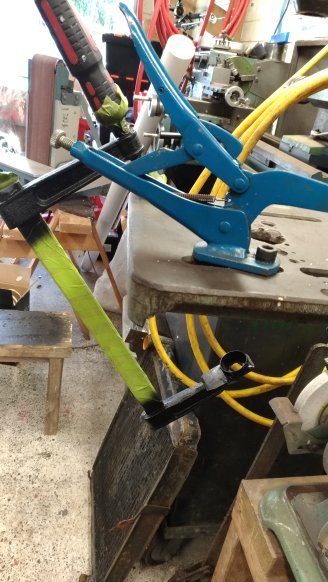
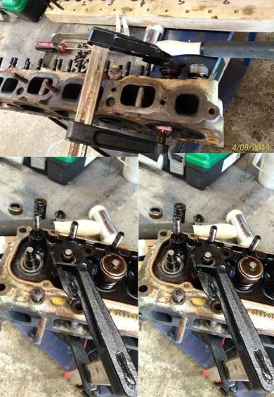
Time to strip the head down. Suddenly I realised I’d lent my valve spring compressor to that guy we all know who never has his own tools (and we always forget his name), who never returns tools……….grrrrrrr! As I’ve said before, combining the lack of an appropriate tool with a good mig welder and the obligatory collection of scrap steel under the work bench is the mother of many a good man-cave invention. Found an old screw Clamp…a bit of cutting and welding. A lick of paint…….. And the custom (i.e. beer, bullshit & bad manners) “Oldschool Holden Valve Spring Compressor” makes its debut.
1 point
-
17th of September is the next meet!1 point
-
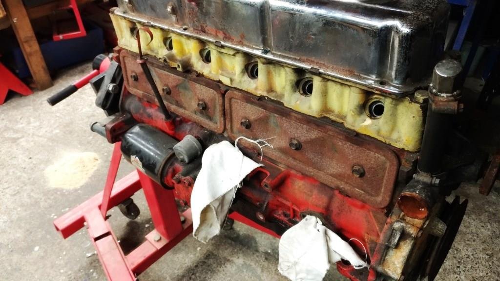
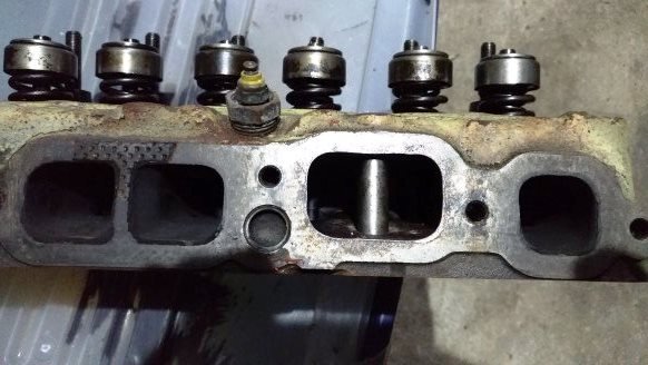
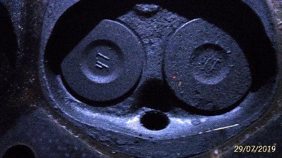
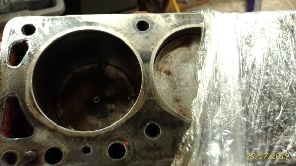
I’d been keeping any eye on a bloke in Whangerai who had been trying to sell a 186 on TM while doing his damndest to scare off any potential buyer by abusing anyone who had the audacity to ask a question on his auction. God I love those grumpy old traders! He was insisting that someone had painted the standard head yellow and refused to post any pictures of the inlet ports. After some months of his relisting I finally put the poor deluded old sod out of his misery by buying it for $300. An early 2-hour drive had me rolling down his driveway at 8 am in the morning, one look at the inlet ports confirmed it had at least a stage 2 Yellow Terra head. When I suggested that as an honest principled rogue, I felt a moral obligation to throw a little more coin in the pot he started accusing me of being a ‘lying young upstart that was talking through a hole in his f***ing head’. As I beat a hasty retreat up the driveway waiting for him to set the dogs on me (with the booty in the back of the van) I had to admit that at 63 years of age, despite the verbal tirade it was great to be called ‘young’ – ya gotta love those grumpy old guys! Couldn’t wait for to to get the head off but work pressure had me waiting for the weekend. As I said in the 1st post of this thread ‘sometimes you just get lucky’ - I stuck it in the engine stand, flipped its lid off and discovered a rather virgin stage 3 Yella Terra covered with the type of carbon that only prolonged over rich running can ever produce. Double valve springs and classic 70’s inlet porting. And just relish in the vintage YT valves! Once cleaned up the flat top 30 thou over pistons felt firm in the bore so Rigamortice and I made the call that we’ll clean up the head, sort out the appropriate sump/pickup combo and see how it runs.
1 point
-
Ok ok What a balls of a job Floor is in Inner sill is in Cab back patch is in Inner cab mount plate is in Outer cab mount is in New sill getting trimmed to fit Not sure if I need an inside sill bracket like what was shown gas axed above, doesn't exist in my parts book.
1 point
-
Nope. That's retarted.1 point
-
ho ho hoooo park your peepers to the 500m mark and check out the latest edition of RX125 escapades As previously mentioned, carb has been doing mega wees out the overflow of the carb bowl, and i set out to rectify this problem. Well fuck me dead this drove me up the damn wall. no matter where the floats were set, it would leak out the overflow. i had two carbs to test out, and both leaked when i put fuel through them. There's not much information on these bikes on the innerwebs. seems they have been forgotten/no one gives a fuck about them enough to put any decent info up online. the closest spec i could find was 21mm float height. After setting both carbs to this height i was still getting wees all over the motor. adjusting the float height either way by bending the brass tab was not changing anything. Only way it would stop leaking was if you set the floats so high that the needle valve was closed all the time. This should have raised alarm bells to me... turns out the overflow tube in the float bowl was loose - meaning any amount of fuel in the bowl would wee out the overflow. perhaps in the ultrasonic clean this had been rattled loose or it was like that beforehand. I guess the other carb i had had a fucked needle/seat which was giving me a false negative type set up. So yea have a video of it running nicely all on its own, no choke no leaks! it does a tiny dribble out the overflow which can be solved with a little fine tuning of the float height, but stoked that its holding its fluids like a big boy. NANGS Can someone whos not a spoon like me embed it haha Only a few minor jobs to do - free up sticky throttle cable - fit joiner elbow thing to airbox/carb and tune properly - get all lights working properly etc - get a mirror - take it for a decent spin - revin!1 point
-
.1 point
-
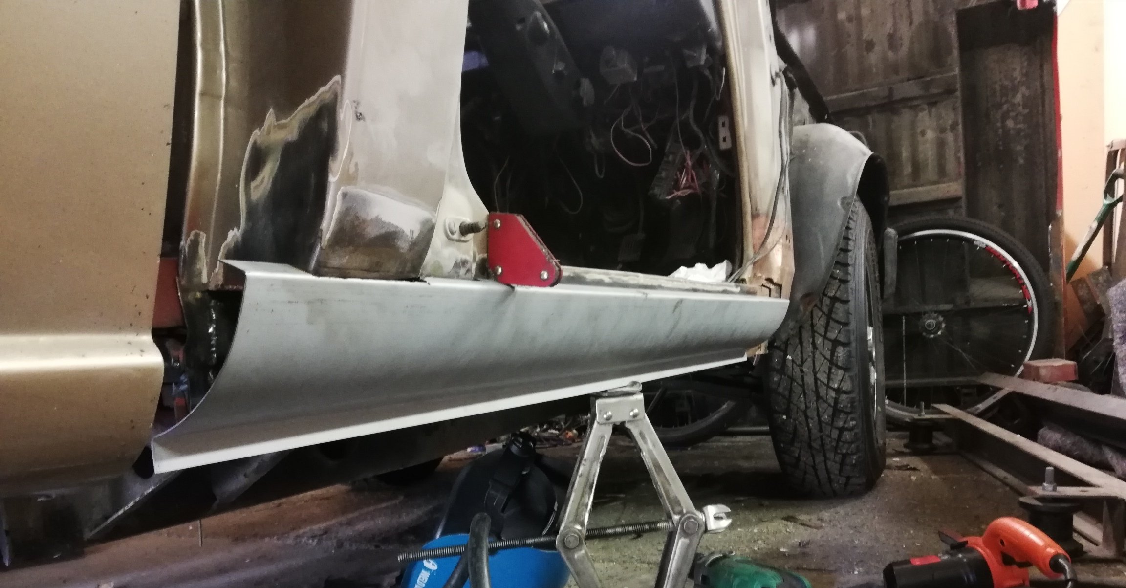
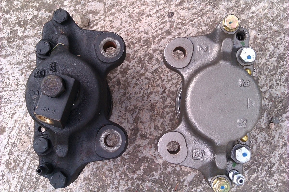
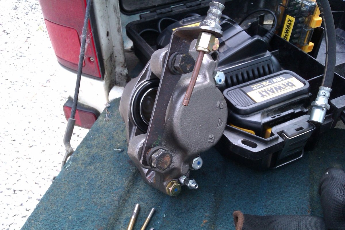
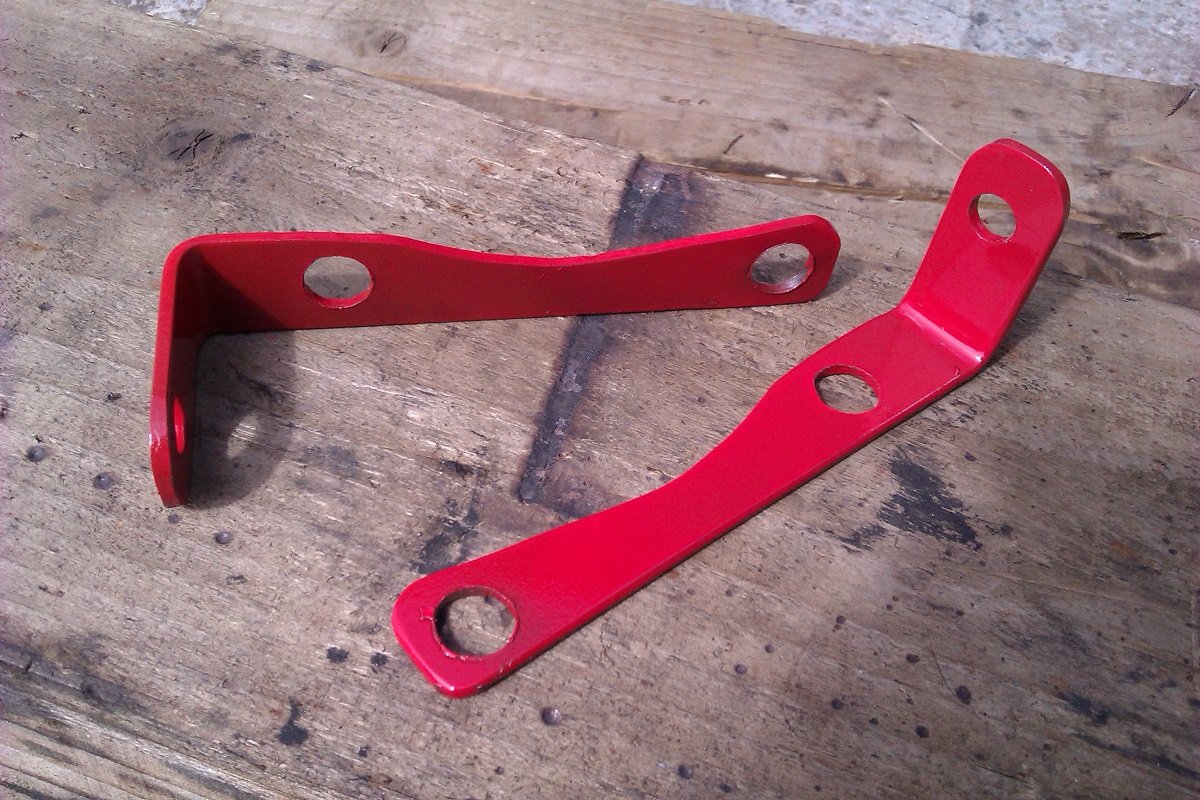
Monday afternoon shenanigans As mentioned the new calipers differ where the pipe goes in. Aftrer a bit of thinking I decided to stick with the standard flexi hoses but extend then using hard lines. This means I have to put a small taper into the end of the flexi hose and make upsome brackets to support the join. Given my usual level of bodgery, I'm quite glad how it looks so far. Pics... Same/not the same A bit of 3mm off-cut I had kicking around. Cut and cleaned up. Trimmed to clear the calipers. This was plan "A" on the length, I cut them back to clear the bumpstop mount. Measuring up for the hard lines. Finished off with a coat of "Sump disaster" red, hopefully the curse won't follow it... Making up the pipes later so hopefully all back together by the end of tomorrow. Woo-Hoo
1 point
-
Sunday of productivity. Water pump back on, filled & warmed up. No leaky, no squeaky. Messed about with the front brakes but couldn't work out a way of fitting the new calipers without it turning into a fearsome bodge. I'll take the calipers & current flexies into the workshop tomorrow & make up some hard lines and brackets. Rear brakes went well though. Offered the shoes up and they looked good enough for a country job Everything fitted perfectly so I can confirm that 1971 Datsun 510 rear brakes are the the same as Hakos. Do with that information what you will.... Also done a vid. Really to demostrate the tappet rattle for comparison after I've adjusted them but it sounds like the cam's not bolted in. It's really not that bad. So that's about it, hopefully full braking will be restored by the end of tomorrow and then I might even give it a clean. Once I've adjusted the valves I'll give it the beans, I've been staying below 4 grand (mostly) because of the water pump but it really feels like it wants to pick up between 4 and 4,500. Thank you for your continuing interest.1 point
-
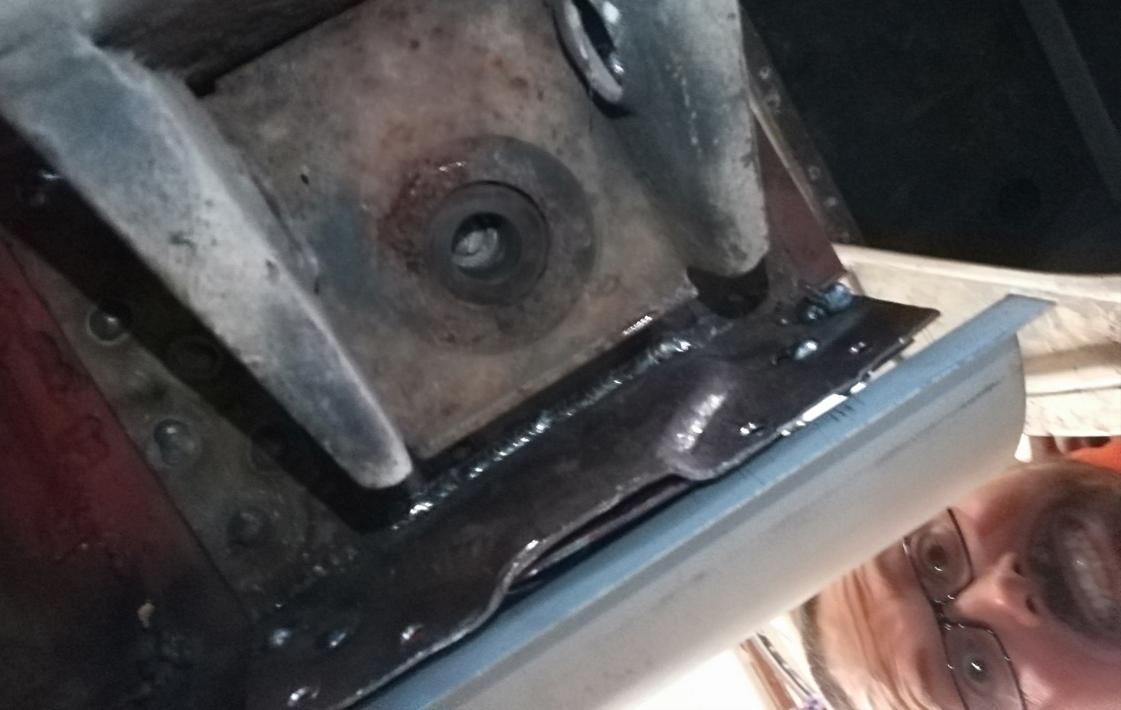
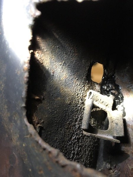
Gotta make sure those rust traps are in the right spot Now to figure out what to do about the cab back. Normally the floor and cab back extend a little past the back of the cab. The entire corner where the two meet has been replaced, however they chose to weld an L section facing inside the cab (leaving the rusty seam in place and bogging to taste). Tempted to cut it all out and do it as per factory, but don't want to take the tray off etc. So might just go to the next bend in the floor and blend it somehow. Now that I have cut out the front and rear of the sill, I'm thinking I my as well cut the middle out too and replace with a single section. Oh yeah, I checked the passenger side mount. I took my glasses off andd turned out the light. Looks fine
1 point
-
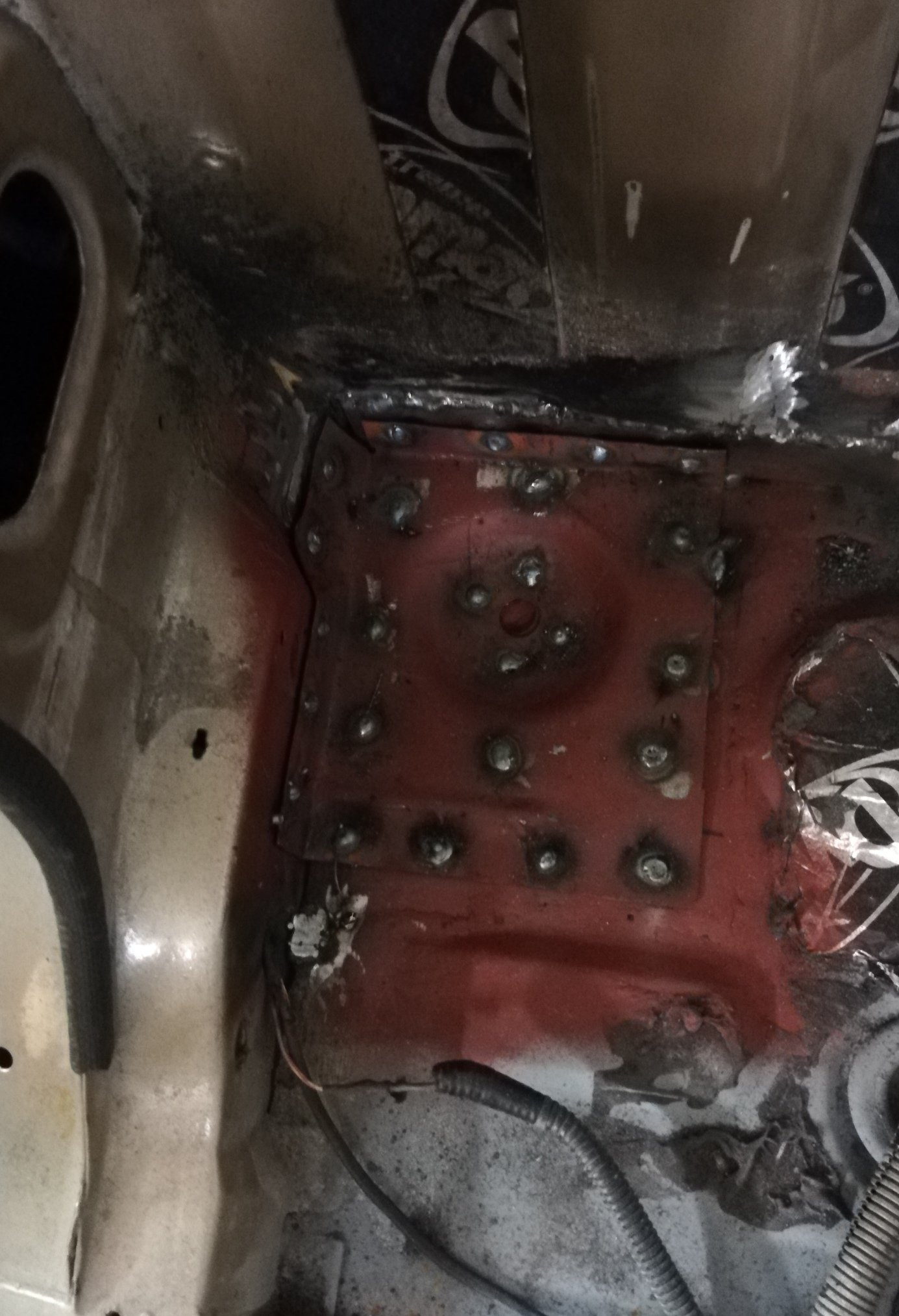
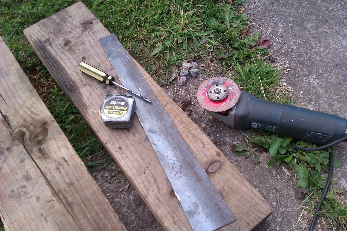
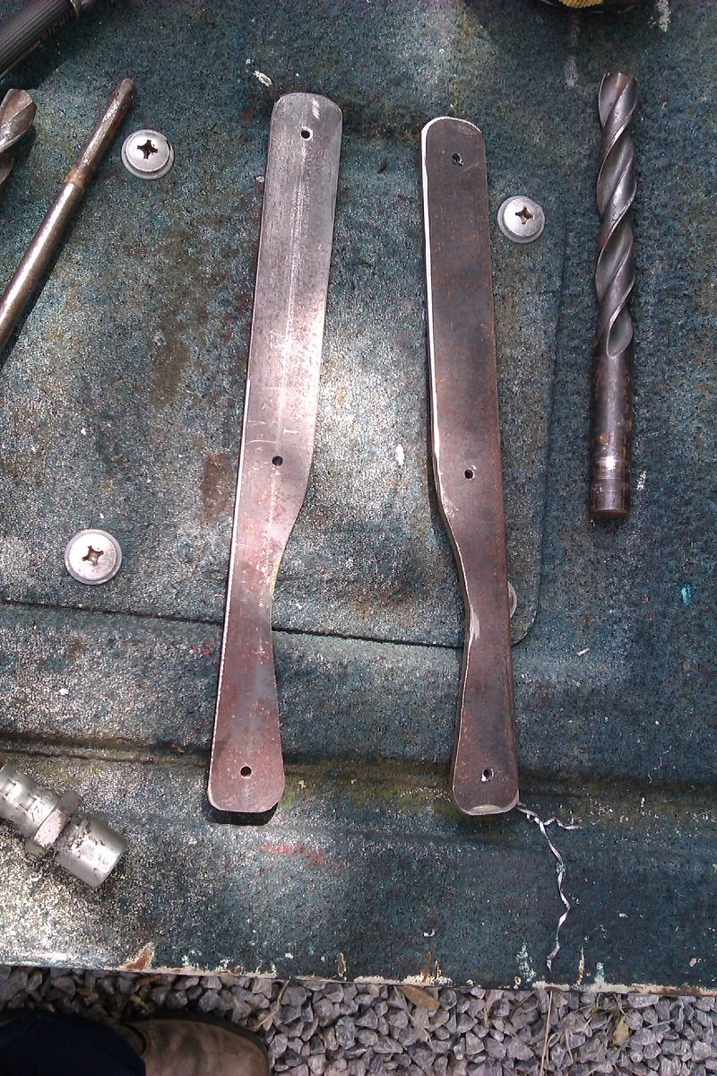
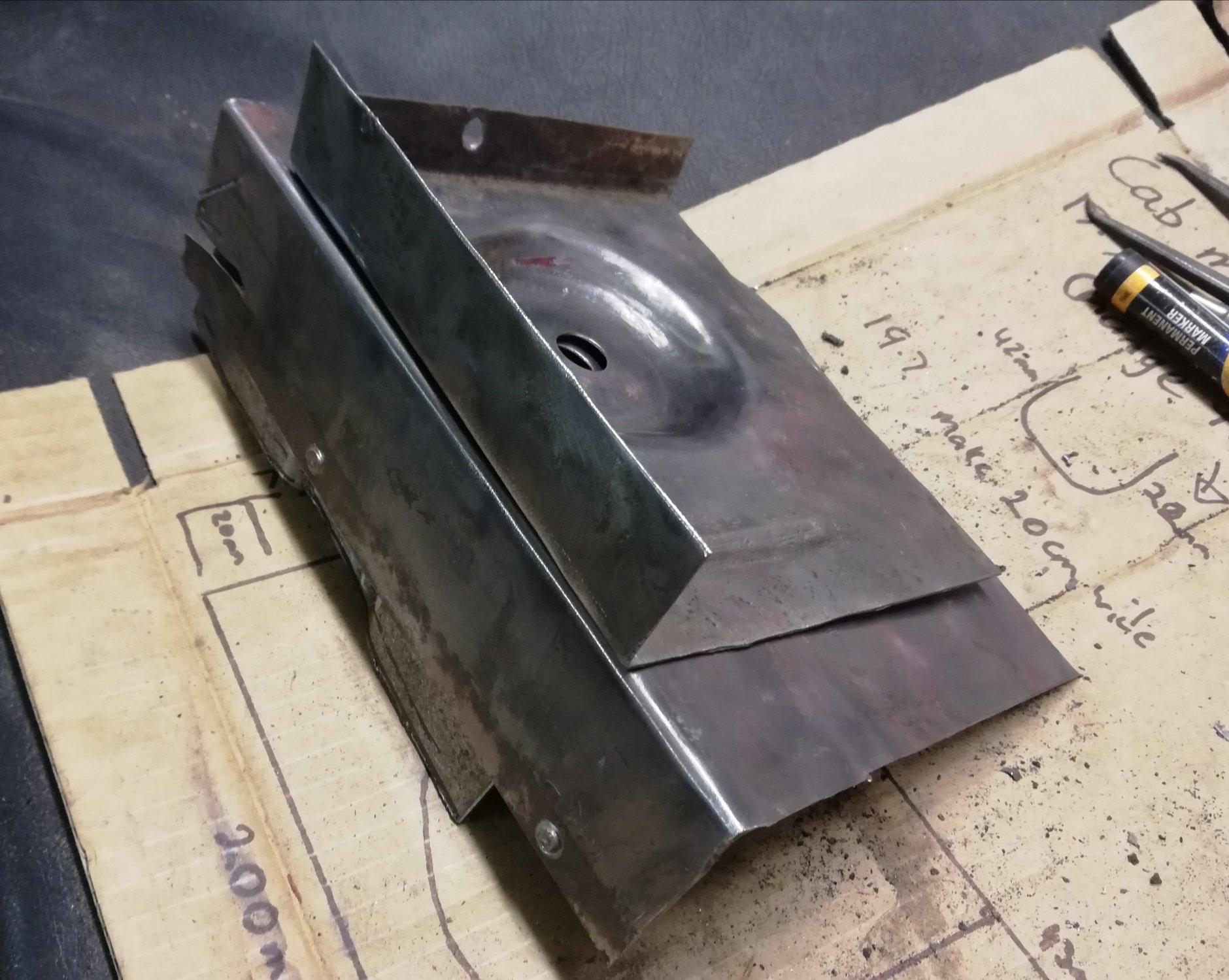
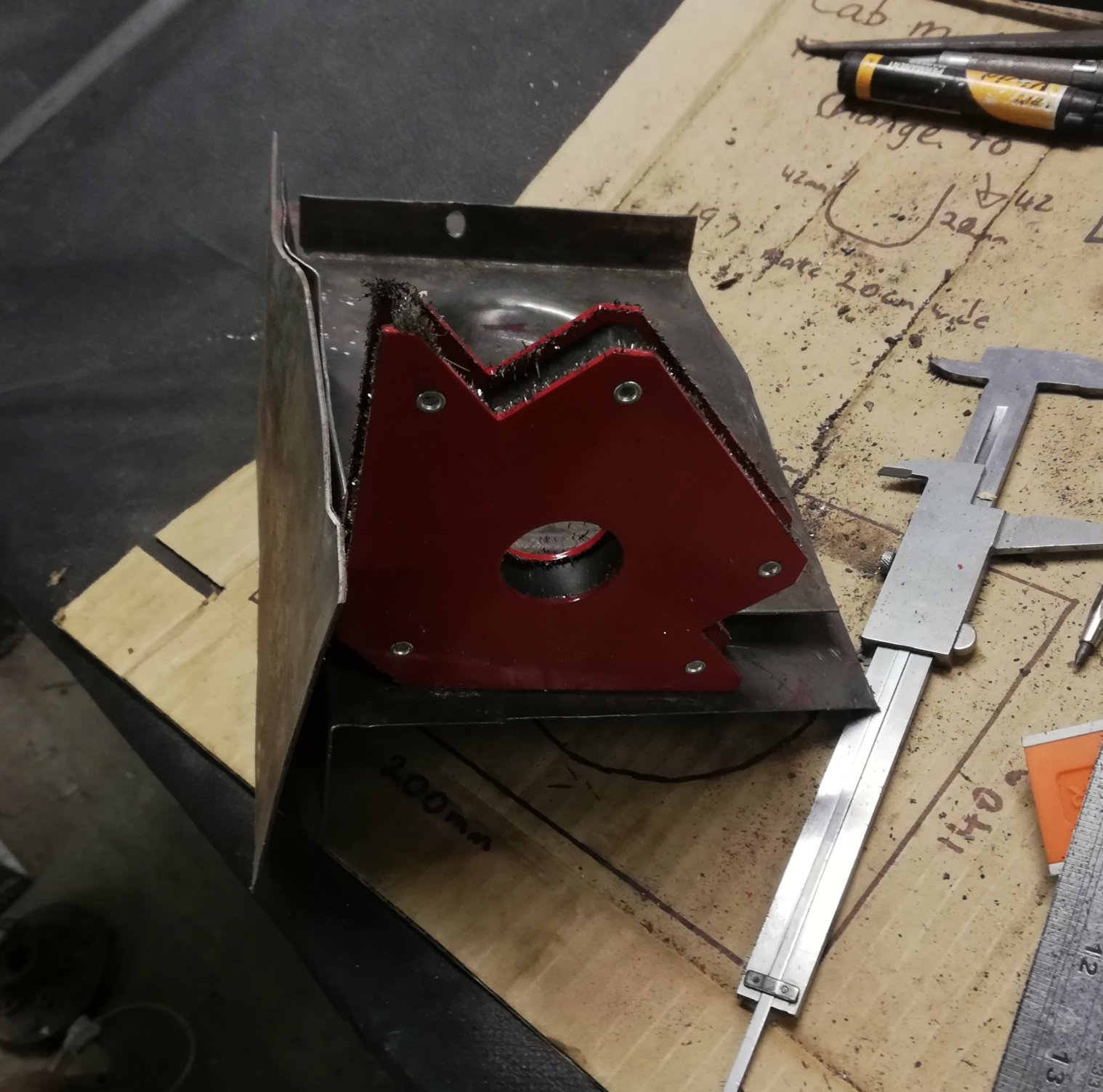
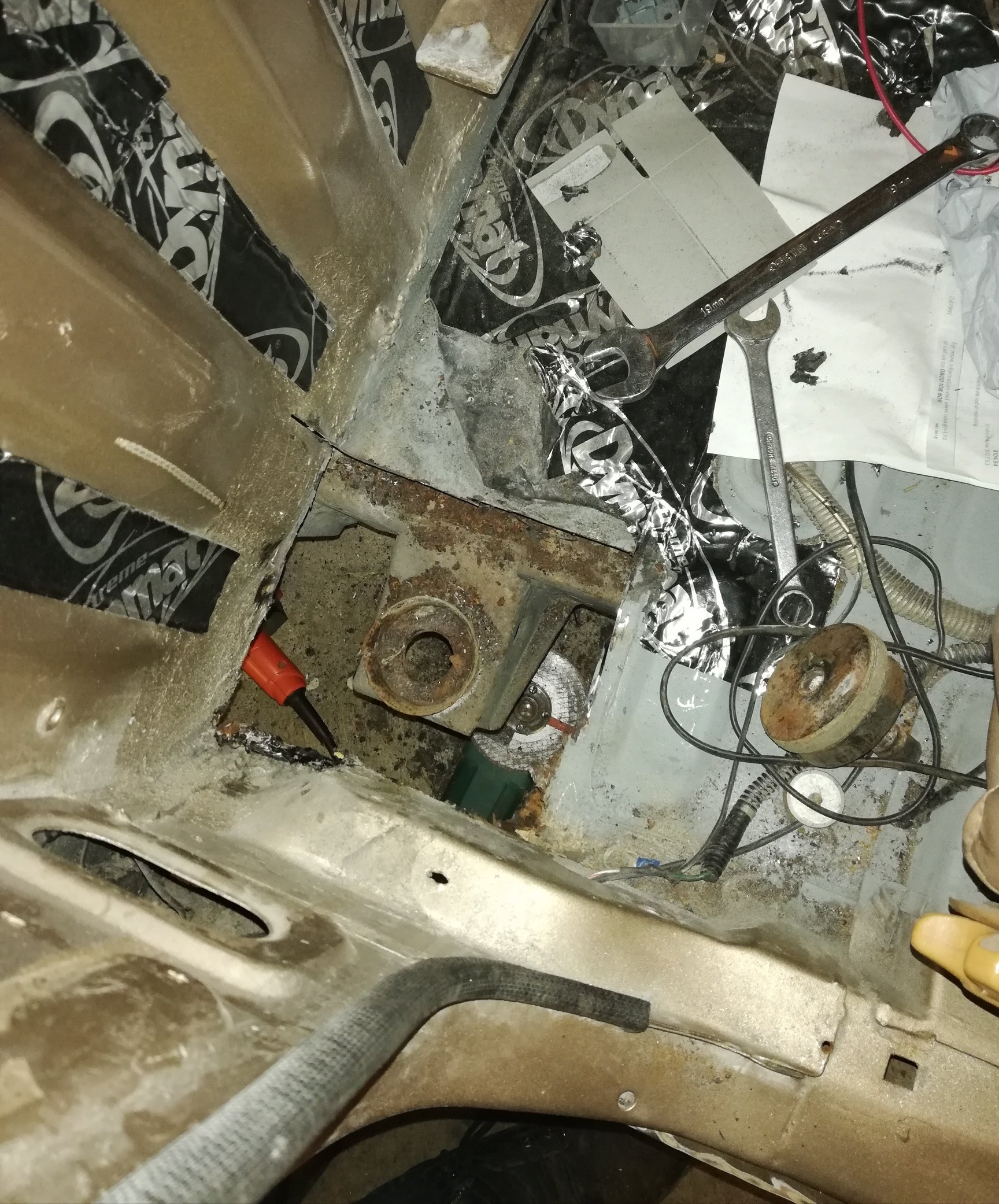
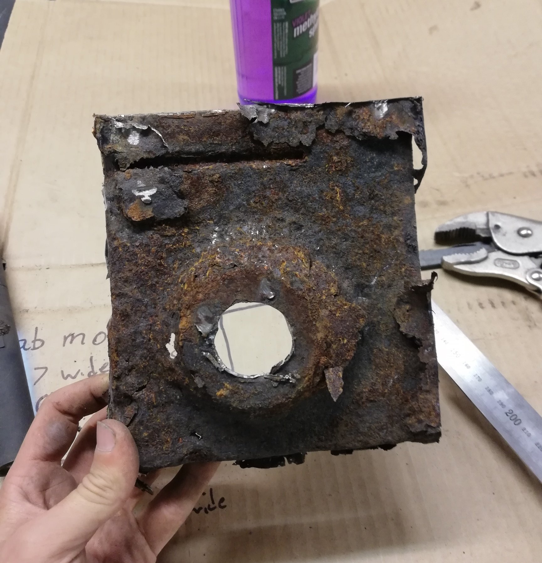
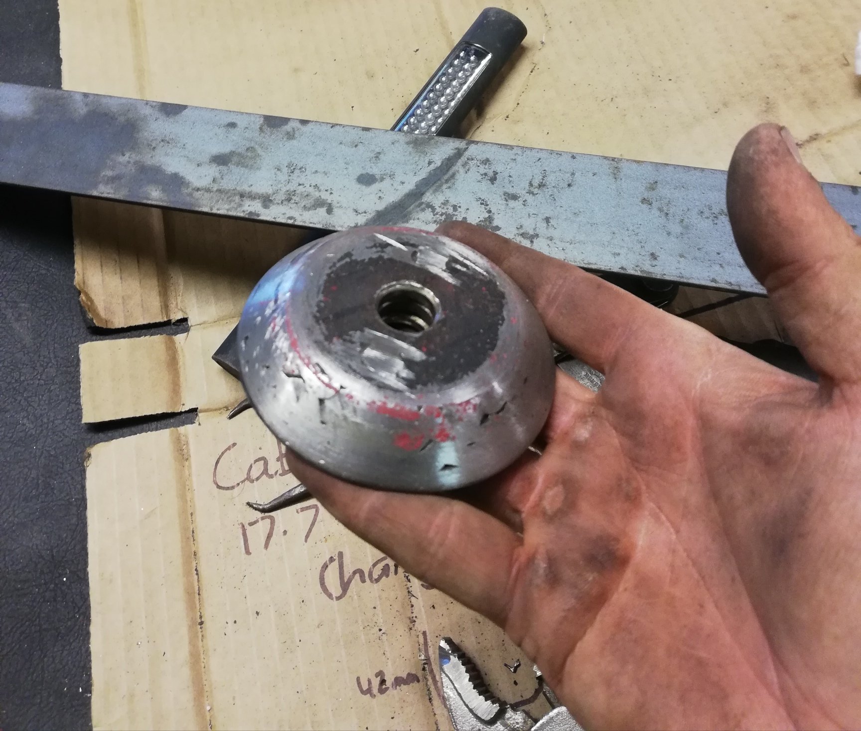
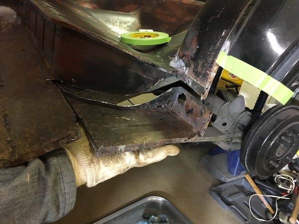
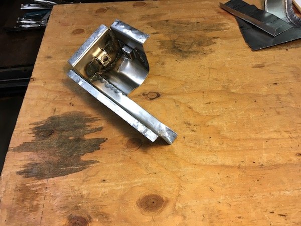
So small problem This is not the floor This is the cab mount doubler plate/floor strengthening plate from inside the cab. The floor here is totally rusted away There was 2 tiny spot welds and some tar holding this corner of the truck to the chassis More and more fell out of it as I handled it. So going to need a new one Made a dimple die I don't have a lathe. I also needed about 15mm of steel. I have some 5mm flat bar and a welder. I did unspeakable things to my drill press and bench grinder to make this. Some 17mm ply backed with flat bar made the female side, but ply by itself was fine tbh. Used some of the 5mm bar scrap as a dolly with my bench vice to add that ridge and my new old kick press to bend the edges. Will trim to fit later on
1 point
-
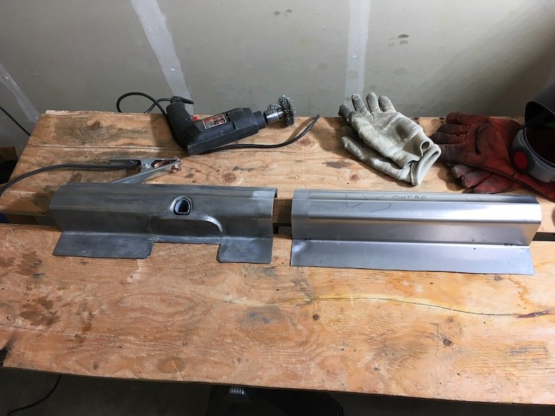
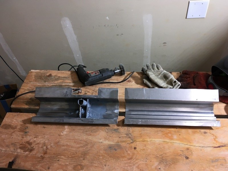
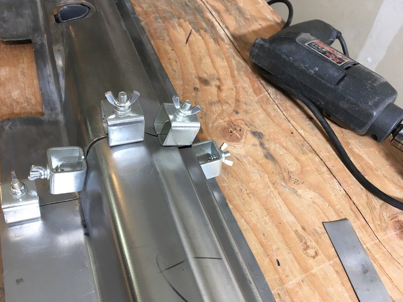
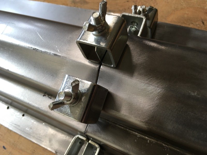
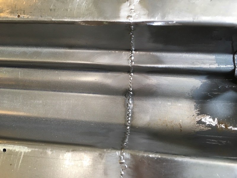
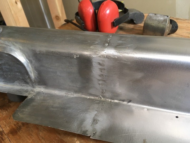
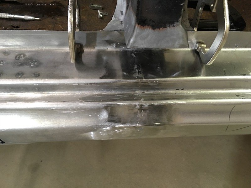
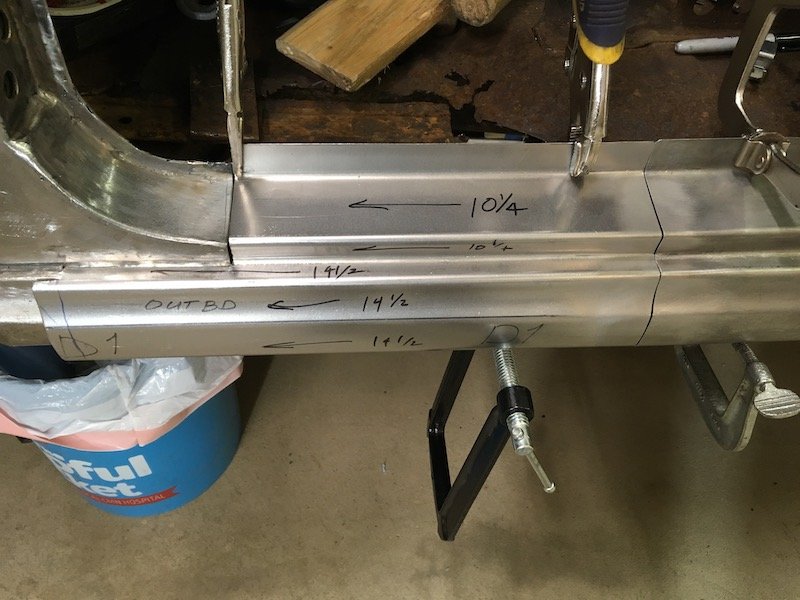
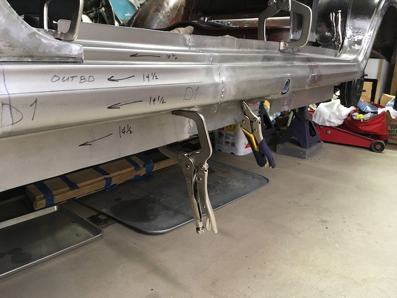
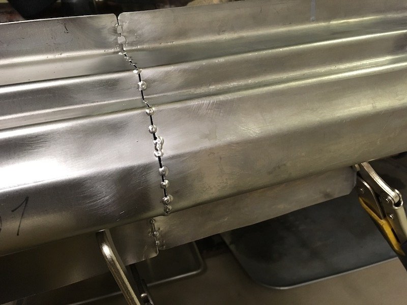
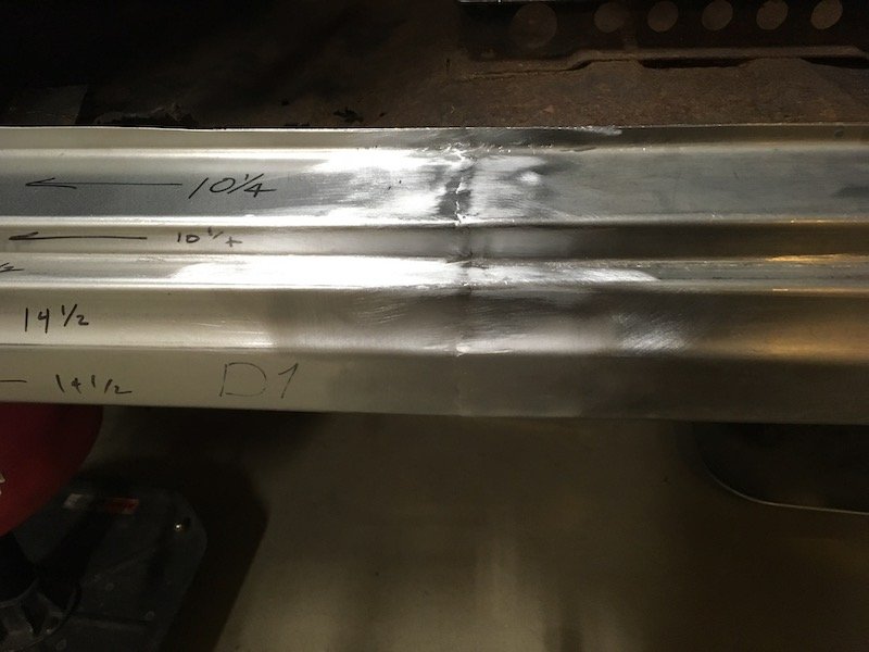
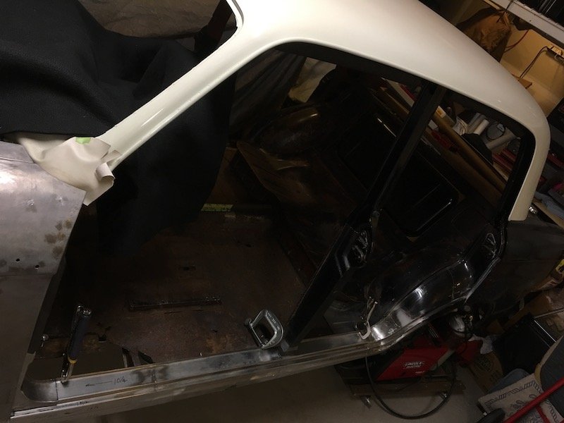
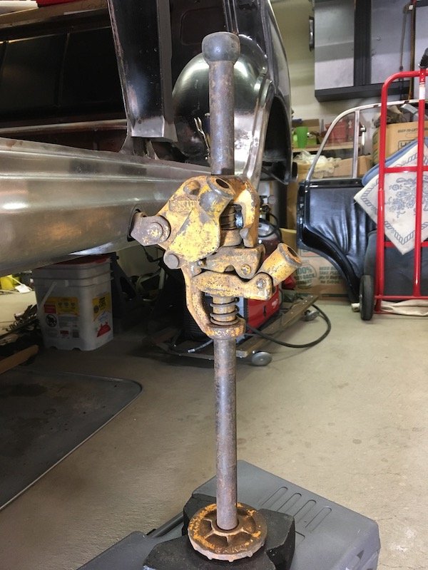
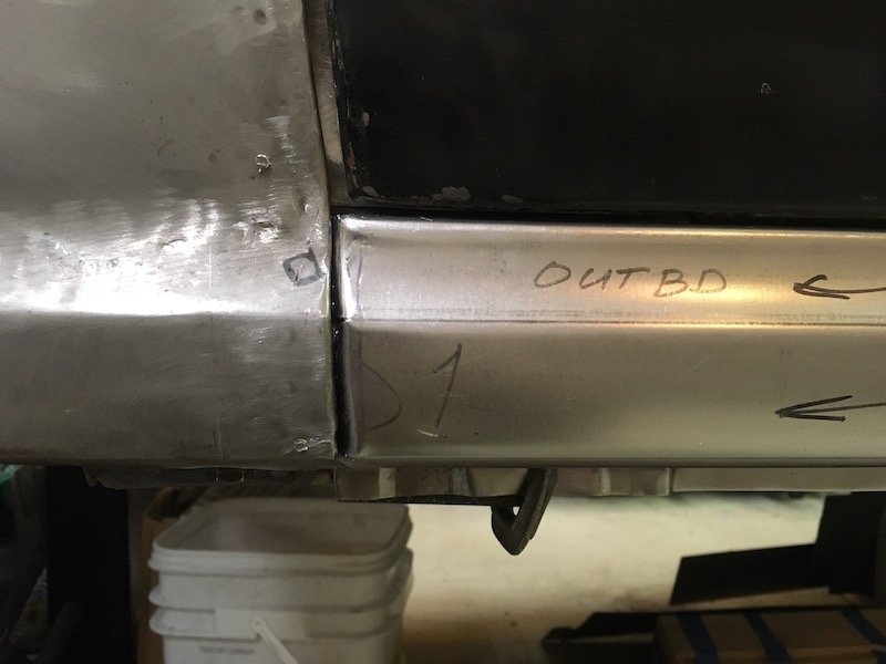
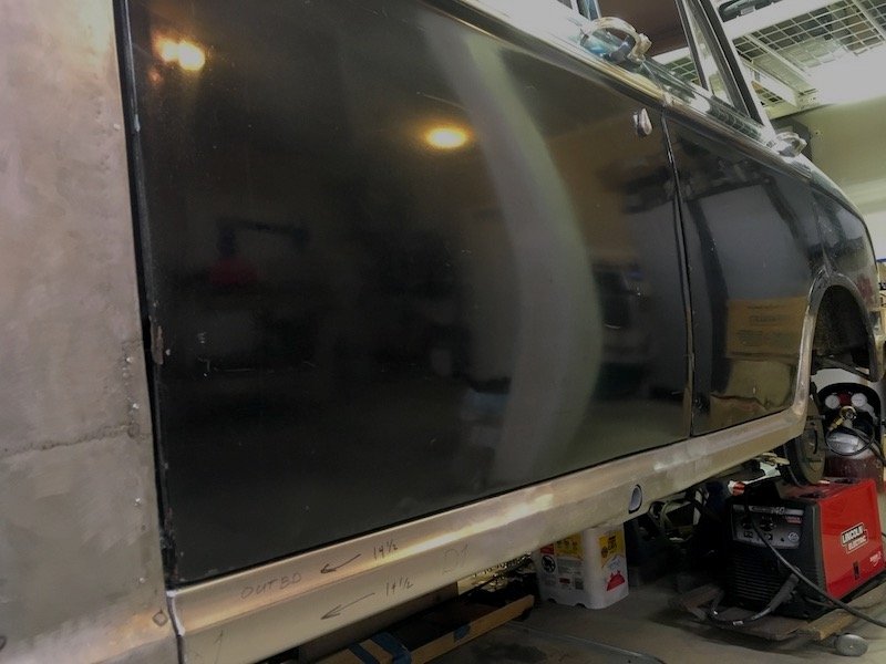
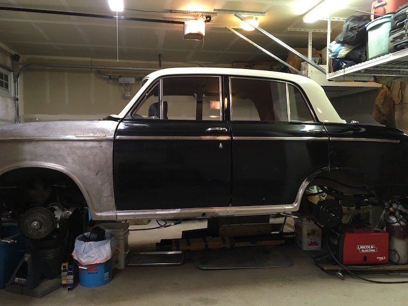
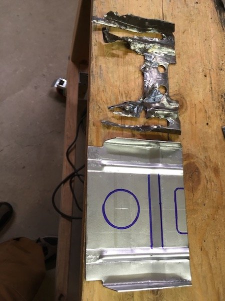
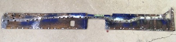
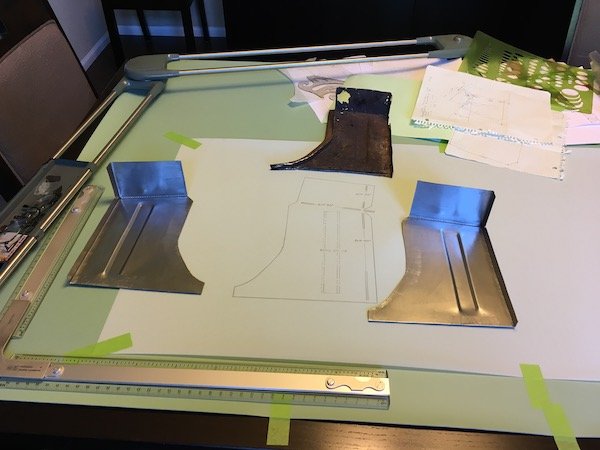
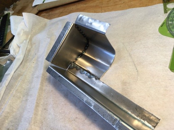
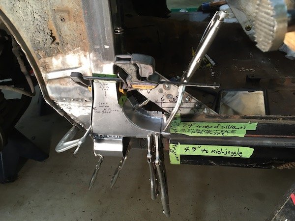
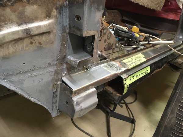
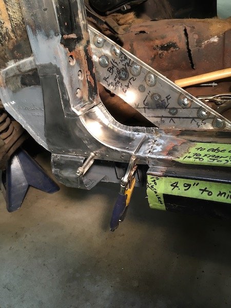
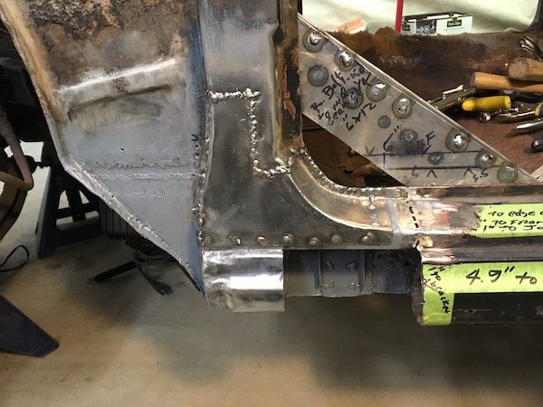
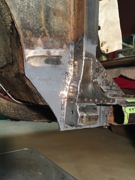
More progress with the Bluebird left side outer sill. Welded the three outer sill segments together. Started with these two shown previously Then I fixed the sill segments together with these little clamp things. These set up a nice gap to make good weld penetration to the back side. Then starting making tack welds. The first strikes in the center of pic were really bad and missed. Remainder of tack welds were usually on target. About 70 percent complete in these pics. Front and back side shown with good penetration. Front side will eventually get ground and sanded flush. Back side gets left as is. Initial grinding and sanding. After that I held the assembly against a bright light and check for pin holes, fill with weld and complete. It looked pretty good in a fit check against the car body. No weird wrapping or anything. Then on to the joining of the third sill segment to the assembly, same as the first. Except I was checking against the fit to the inner sill on the body before tacking, and after initial series of tacks, because there is a slight bow or curvature on the body fore and aft and I wanted to make sure of no issue. Did a little more rough trimming of the forward end as well so as to permit tailoring a nice fit up against the A pillar and lower stub later on. Finished weld of the last segment. Overview of the situation Then I decided to play with this. No, I did not actually try and jack the car up, just having fun with it. Later on I bolted the doors on again, probably for the fifth or sixth time, and did a final check for gap along the lower edges. Plus I formed the forward edges of the sill assembly to mate up with the A pillar stub with just the right gap next to the fender (or wing, right?) As seen underneath in above pic, there are several joggles along the lower flange to accommodate fit against several parts that are layered on the vertical inner sill plate. Below, the gaps look decent and body lines of door to sill are flush. Installed some trim to show off for the camera. Discussion: https://oldschool.co.nz/index.php?/topic/60267-marts-pl310-61-datsun-bluebird-sedan/
1 point
-
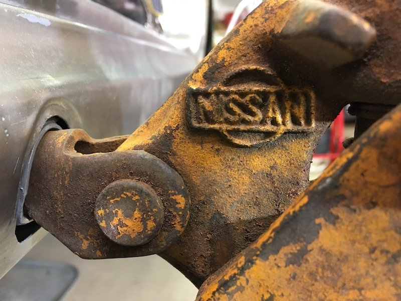
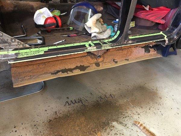
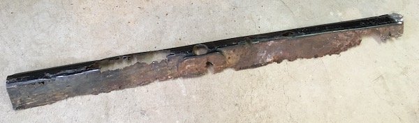
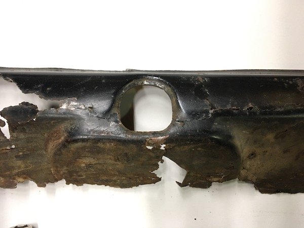
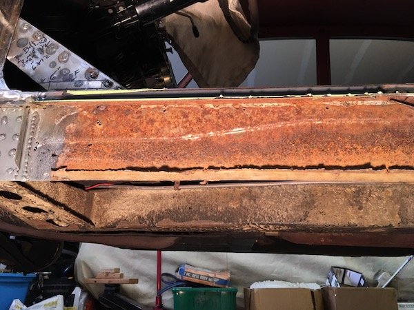
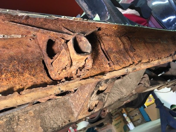
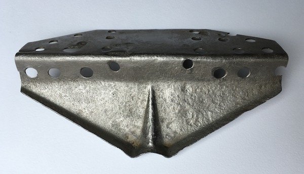
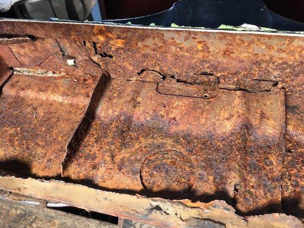
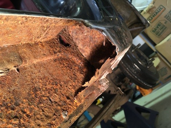
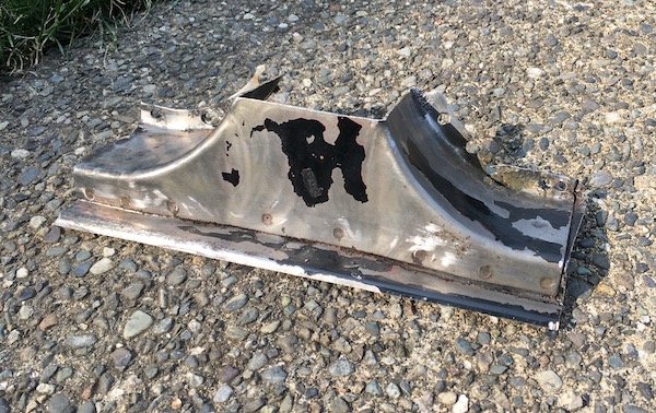
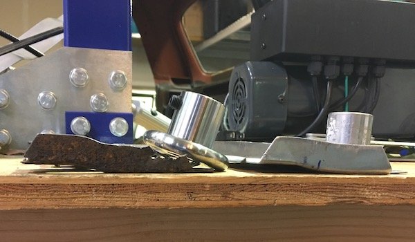
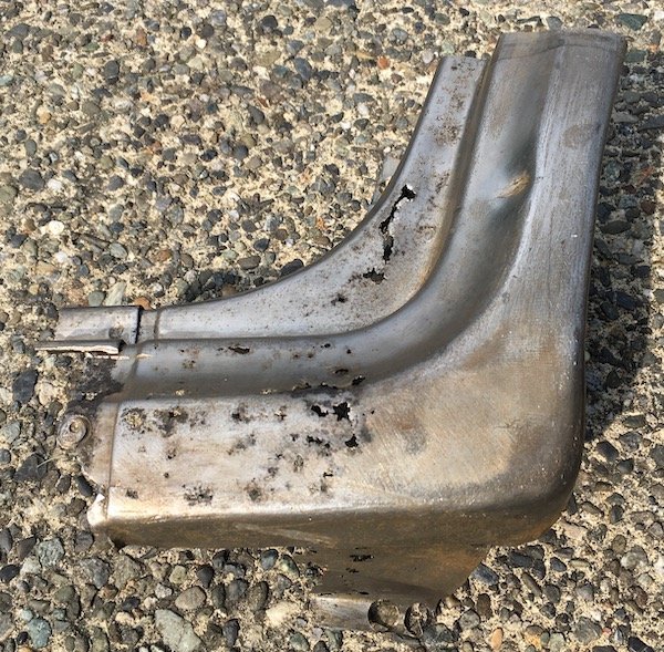
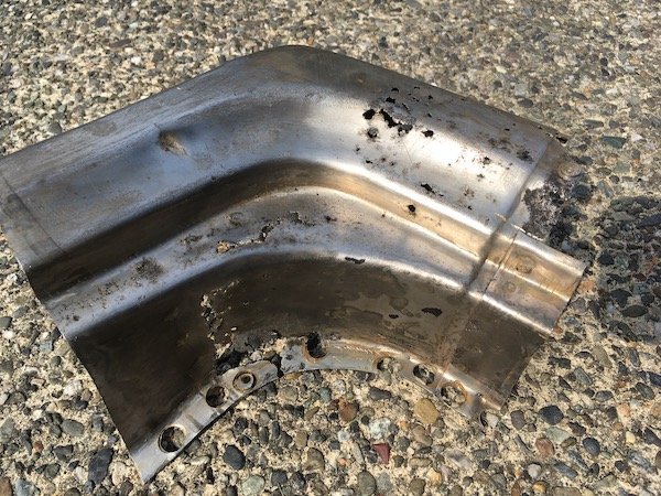
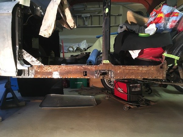
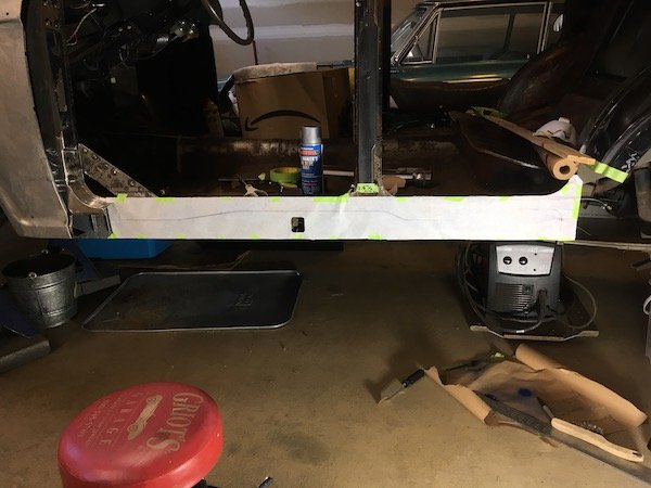
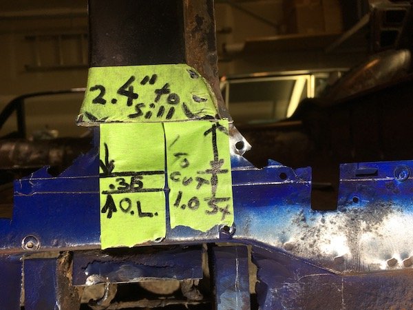
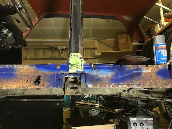
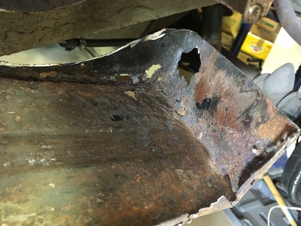
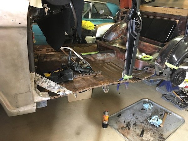
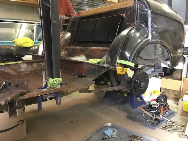
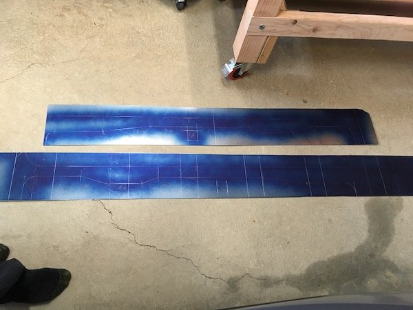
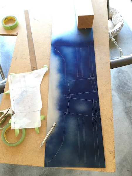
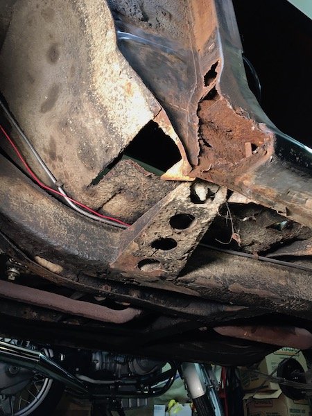
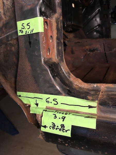
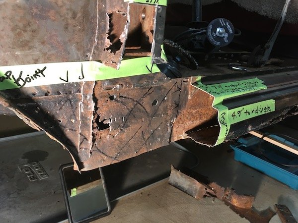
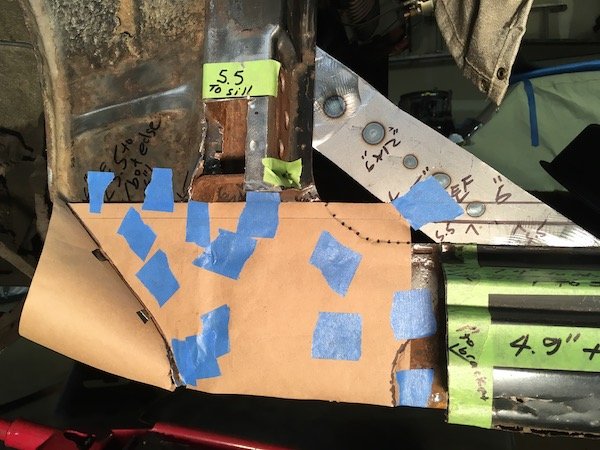
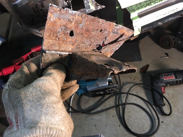
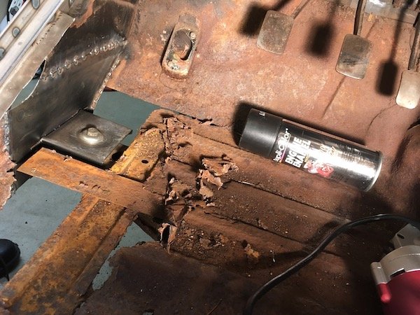
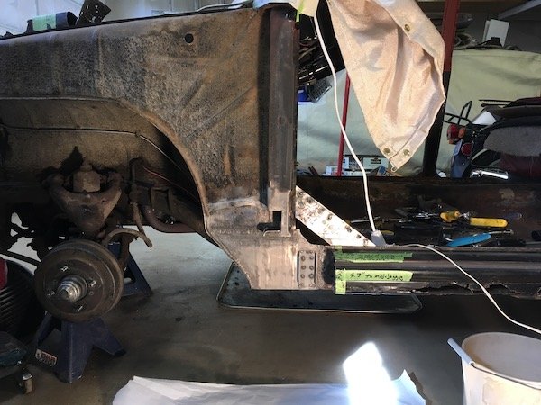
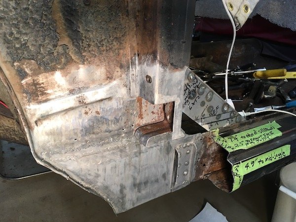
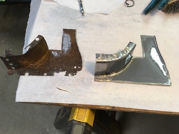
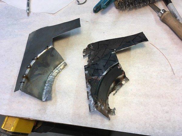
Removal of more rusted metal from the 61 Datsun Bluebird left hand side outer and inner sill, 'B' pillar, 'C' pillar and side of seat pan. A huge hole in the car structure is the end result. This gets very ugly and you may want to look away if at all squeamish. No need to panic! Almost of this is going to be replaced with new steel, but it is a very slow step-by-step process to make these parts from scratch. There is nothing here you can just go to your computer and order or even find in good condition in an auto wrecking yard. It is a heck of a learning process that will be applied to the so far untouched right side of the car. I get started by using electric metal shears, slicing and splaying open the outer sill for internal rust inspection and to understand what details are inside with respect to the side of body lifting point. I had hoped at least the upper sill and inner would be salvageable so I cut a relatively clean line against a tape edge at the body line. The outer sill immediately swung open at the lower pinch weld and then just falls off. Notice the slightly bumped out area below the body lift penetration point. This will be duplicated in the new steel panels later even though I may never use the factory lift jack tool. I do still have the jack but it is worn, unstable and deemed unworthy for safe use. It would either lose grip internally and slide downward suddenly, or the small base plate could kick out at the ground and punch the upper shaft end against the door and make a big dent. Maybe the old lift jack can be repaired and improved or maybe not. Sheet metal form detail of outer sill lift jacking point Eventually, the rusty inner sill is to be separated at the left next to the new 16g steel from the previous 'A' pillar repair and new metal lapped in at the back side of the gusset shown. If you look closely, you see the fuel line and wire to the electric pump. That line is soon removed to avoid a fire hazard. Moving further aft, we see the reinforcing structure around the lift pipe, or what remains of it anyhow. And behind that what I call the joggled gusset. This upper gusset, the near one with the three ribs, is heavy gage steel and salvageable. I thought incorrectly, that to remove the upper part of the sill, that the upper gusset would have to be separated first from the pipe. Actually the top of the pipe is not welded to the upper gusset at the notched contact point. Only the side brackets are welded to the pipe and they are weak enough to just pull apart from the pipe. I could have just lifted the upper sill right off once the regular pinch welds were drilled out. The salvaged lift pipe gusset plate. I ended up with a lot of holes from spot weld drill outs that will be used for plug welding later on. This is the joggled gusset plate that is on the opposite side of the inner sill with respect to the body mount bracket on the other side. This gusset is deemed too badly cratered and rotted and will be reproduced. I cut it out before removing the inner sill by cutting around the perimeter after a futile attempt to search out and drill out all the spot welds. Things aren't looking to good above at the base of the 'B' pillar. Lots of otherwise hidden rust damage. I'm going to cut 'B' pillar base off and repair. The damage and repairs needed to the now cut off 'B' pillar is shown in the light. I subject the 'B' pillar to an electrolysis bath to remove bulk rust and identify the salvageable sections. A lot of it is still good and will be cleaned up and reused. Portions near the pinch weld are bad and the flat horizontal section deep inside is shot. Outward facing sections are perfectly good. Jumping ahead here a little bit since I did not have a good pic of the freshly removed gusset plate. As you can see, it was total destruction to remove it. A real light show with all the flying sparks! Shown above is the newly made replacement. The joggle or step was made under force from a hydraulic press and an opposing stack of offset steel bars. The aft end inside the sill is heavily cratered and holed. Thus I go to the extreme of cutting off the 'C' pillar, aka dog leg, for complete repair as the hidden damage inside is total rust out which will otherwise just continue. Where there would be an end of sill block off plate in the far back is really just rust powder stuck to the asphalt undercoat. At the lower pinch weld, the flange of the outer sill moves upward leaving just the inner sill plate poking down about a half inch. Why? Just looks a bit odd. Probably to match and fit the slight difference in contours at the 'C' pillar. The now cut-off dog leg ('C' pillar base). About 60 percent or more is perforated or too thin to reuse. This part proves difficult to reproduce. It is still not quite right after patching it up section-by-section off the car. I tried, and will tweak it a bit more now that it is welded back on the car. I might do it differently when I go to work on the right side of the car now that I know which areas should be cut out. The now fully exposed inner sill plate. This was a bit of fun. Before drilling the spot welds and removal, I cover all the step contours with blue machinist paint and scribe on the metal the intersection points to permit accurate measurement of the sill. The inner sill steps out about a tenth of an inch where the flange of the floor is butted against it for nested fit. In addition to recording measurements prior to removal of the inner sill, I make a paper overlay as a secondary backup to sometimes flawed note taking. I've also made a full size drawing on mylar as yet a third method to help reproduce the part. Key measurements at the 'B' pillar overlap (O.L) and inner sill. It's starting to look pretty messy and getting worse soon. Inner sill is drilled of the spot weld connections to the floor flanges and removed. The underfloor brackets are cut off at their flanges because these brackets are severely beat up from impact damages. The bracket for the body mount is planned for reuse, if it is good, so the flanges are left intact. Not reusable! As final act, the side of rear seat floor pan is cut out. Is there a name for this thing? This proves to be a relatively easy and fun part to reproduce because of the straight bends and box shape. Just a little challenging to butt weld into the side of the seat pan later on. A rust hole big enough for a mouse to climb through. And they did, sometime stockpiling grass seed and such here and there. And now the huge ugly hole in the car! A preview of making new parts and closing this chasm up. Making left and right hand parts where possible. I'll probably focus on the inner sill next post. More later.
1 point
-
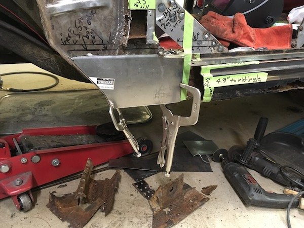
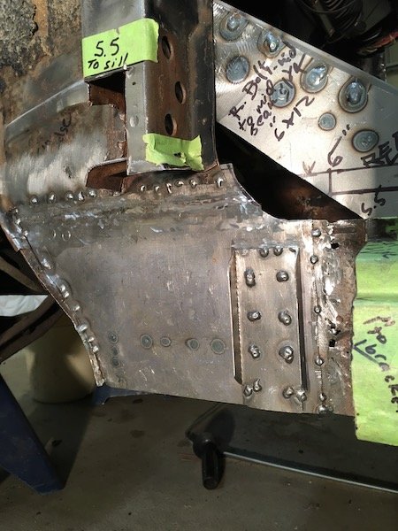
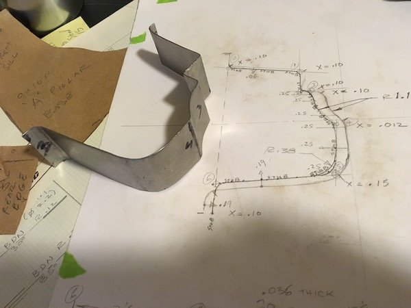
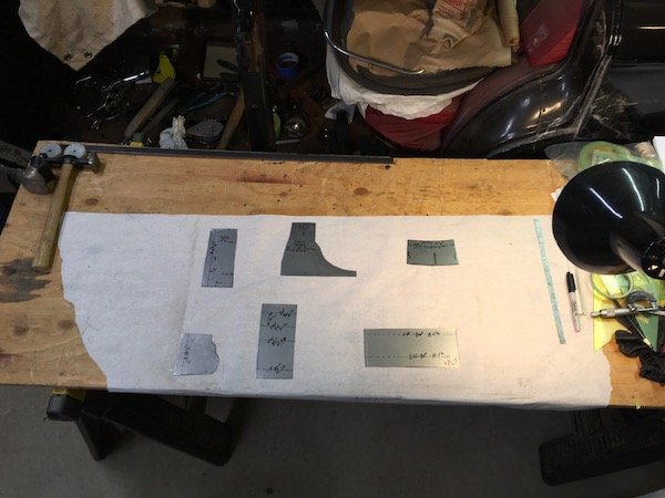
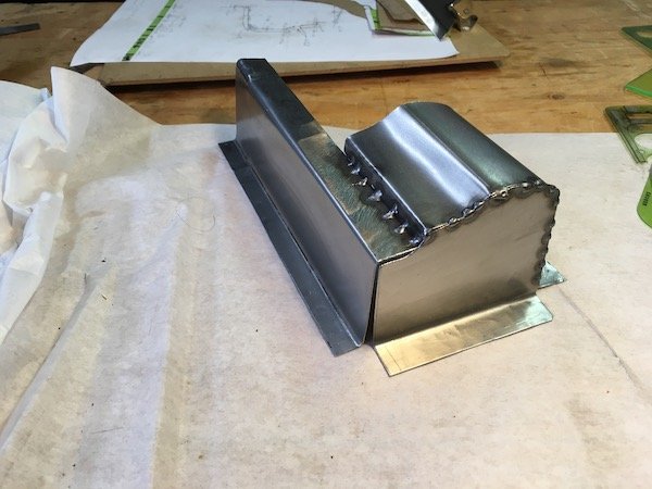
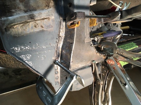
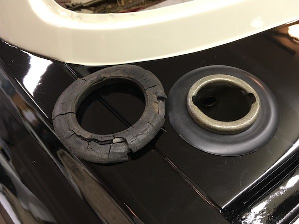
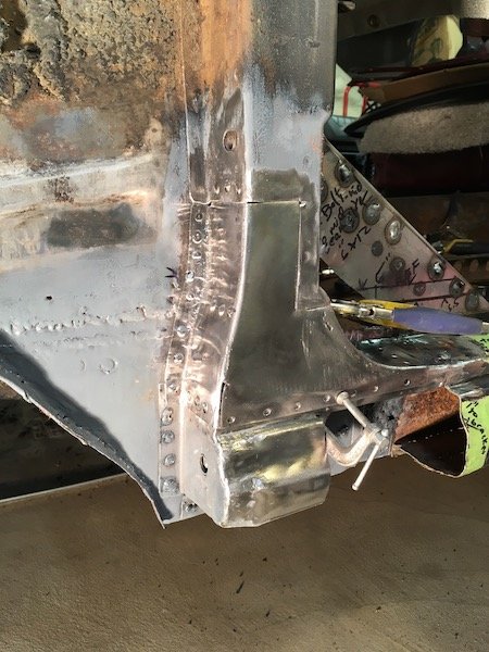
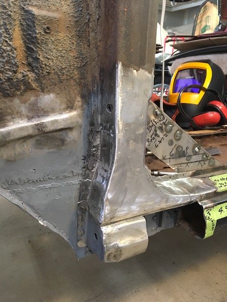
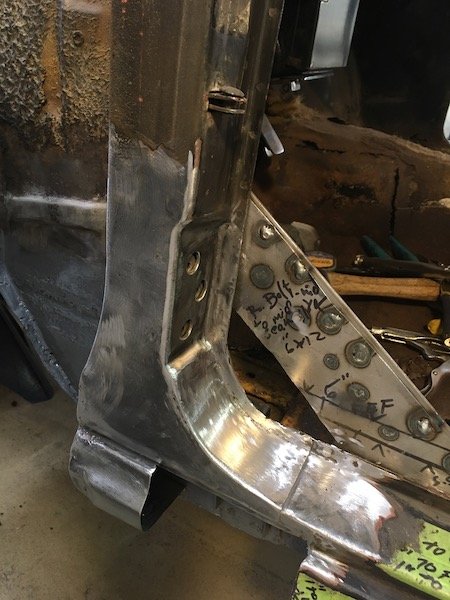
Repairs to the 61 Datsun Bluebird left hand side 'A' pillar (or post) The starting situation. More than a little rusty. Several portions are completely gone. I started by making reference measurements Cutting the remainder of the forward sill stub off Reinforcement was added before cutting the inner sill plate out. Making a paper template for an inner sill patch Cut it out Sizing up some 16g steel sheet Finally the patch, gusset plate and body mount bracket (on inboard side) is welded. Had to do it twice as it was placed crooked the first time. Still learning how to weld with the MIG. I should have turned up the heat for these welds against the 16g, still a bit cold with too much build up. The rest of the inner sill going aft will get cut and replaced later. Inboard side Did some sketching and cut out some flat bits to make the rest of the pillar They may not match perfect, since some of these cover undefined areas, but they are better than empty air space! Beginning of the outer sill forward stub Forward sill stub inside Initial fit checks, and adjust and fit and repeat Added the floating nutplates A view of an original style retainer for the square nut. Bent over 180 to get a wrench on the nut after torching a hole in the inner panel. Notice only one tab is welded to the metal. From the right hand side pillar that is toast. The area is phosphoric acid etched and prepped for weld and protective paint where it can't be reached later Another viewpoint Beginning to weld it. Finally I'm getting the plug welds hot enough to penetrate well and lay flat. The reproduced upper bits. Didn't like the pie cuts but it worked Same as above, flipped over This metal work was getting tedious. For a diversion, I located a Nissan rubber grommet to replace the rotted rubber on left. This is the typical state of the rubber parts all over after nearly 60 years. Okay, back to the business of welding the parts onto the Bluebird... Prepping more of the soon to be hidden innards Get it welded! It's taking shape Getting there Now to just grind and sand the welds flush It looks not too bad. Solid metal again! The rest of the outer sill will be reconnected at the stub joint much later. Next posting will be removal of multiple parts, including; outer sill, 'B' pillar bottom, 'C' pillar (or dog leg) and remainder of inner sill.
1 point
-
I needed to somehow get the Dio stem to fit onto the melody frame. The melody tube is longer and thicker than the dio. Since IT was thicker I gambled that the thinner dio stem tube would fit the melody. Both frames had a date with the grinder and it mostly worked Melody vs dio I'll save those bits for mounting the plastics later Some A+ Grinding skills Couple of tacks and a test fit, Its a bit high so I raised the tube as much as I could. GTFO stand, I can't mount my engine properly In my wisdom I threw out the dio handle bars and of course the melody ones don't fit the Dio stem. I think one of the other nifty bars fitted the dio stem so I'll check my hoard1 point


.jpeg.9062206fae4687c28fcac634f9f6ef31.jpeg)


This leaderboard is set to Auckland/GMT+12:00