
Leaderboard


Popular Content
Showing content with the highest reputation on 20/09/22 in all areas
-
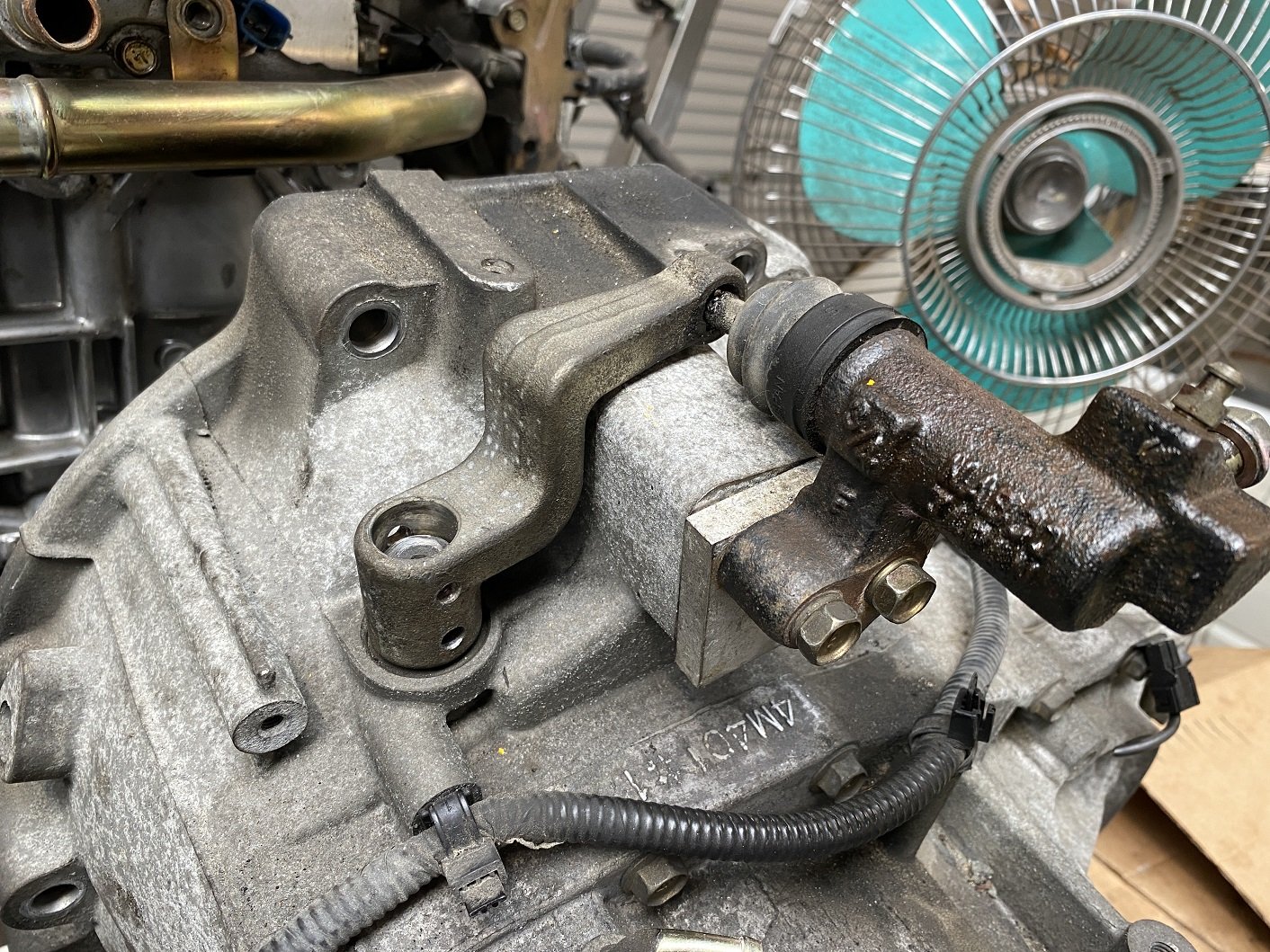
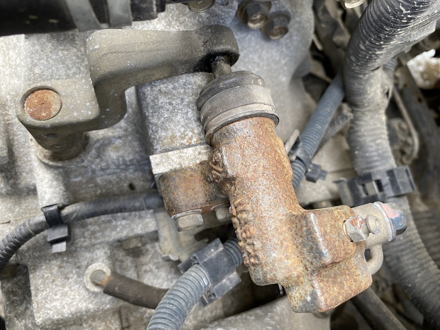
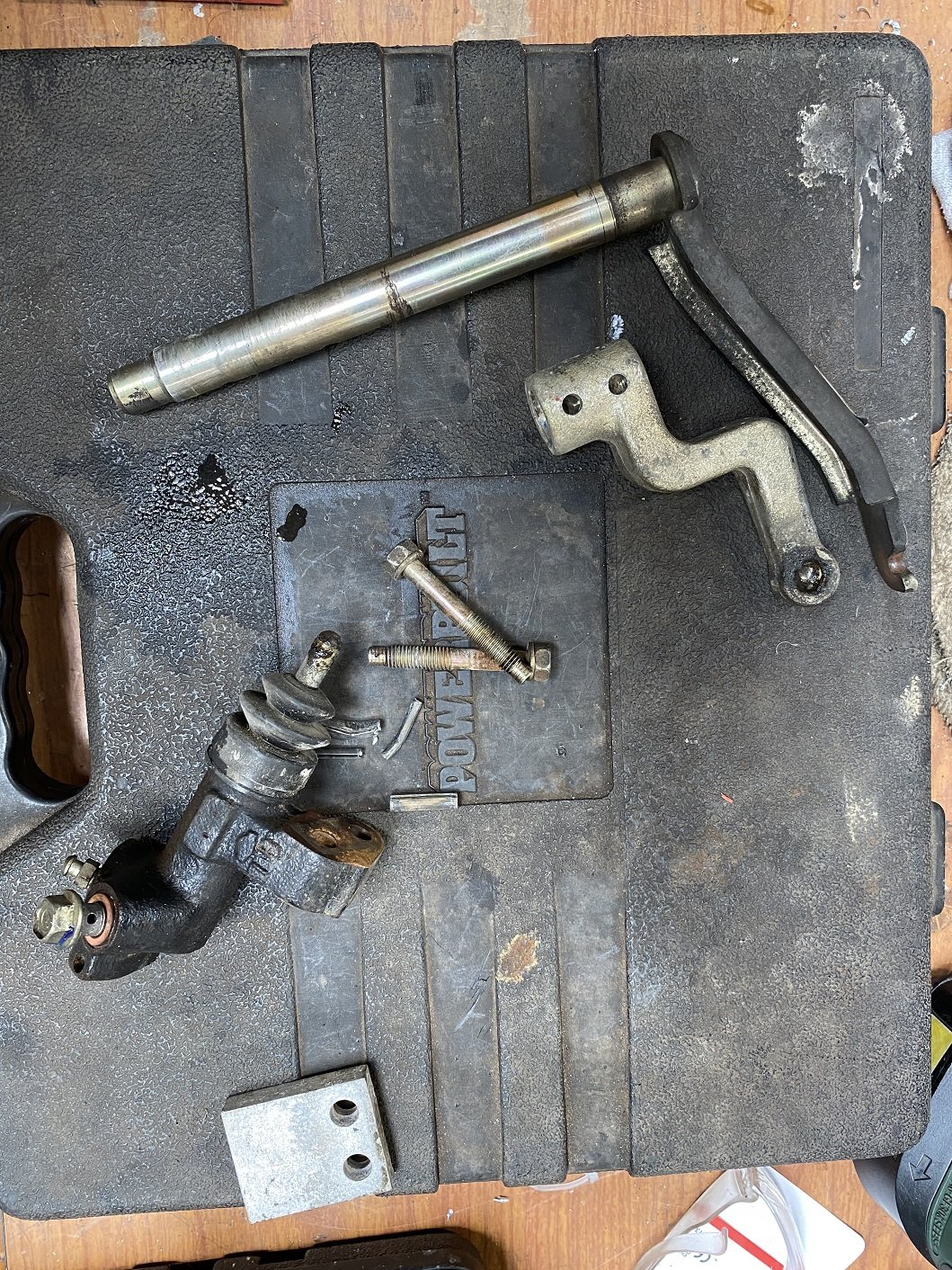
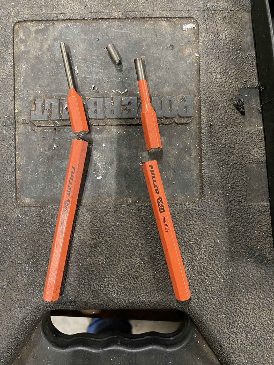
So the mini is a hydraulic clutch and the K11 gearbox is a cable clutch. I prefer to go for a hydraulic clutch because the lines can be tucked away. I was thinking I was going to need to make a big bracket and stuff for a slave cylinder. But then random PickAPart perusing of manual Nissans turned up an N16 Pulsar. The gearbox is very similar to the March, with a QG15 engine... but it has a hydraulic clutch! The aluminium spacer seems like such an afterthought. But I have seen pictures of other N16 and they have the same spacer. I did find another later model N16 which had a cast spacer that does look like a factory part... I forgot to get it, ran out of time. I CBF removing the whole gearbox in my lunchbreak to take the whole pivot shaft assembly, so I planned to knock out the roll pins and just take the lever arm and slave cylinder. So lunch break day one. Got the slave cylinder off. But my pin punches are too long and there is no room to hit them with the hammer. FINE THEN!!!! They are nested roll pins, so need two sizes. Lunch break day two. Soooo I strongly suspect that the workshop manual for removal of this arm starts with "separate engine and gearbox and rotate clutch pivot shaft for clearance". Shit, the bellhousing is in the way of knocking the pins out. Que tool abuse and using my big screwdriver as a chisel to bash the shit out of the protruding part of the roll pin to flatten it, allowing me to bend it slightly, just enough so it rides up the bellhousing instead of driving directly into it. 45 minutes of bashing and swearing and I managed to get the pins out. Next step, cut the welded arm off and machine it smooth in the lathe. Ah... the shaft needs to be a bit longer. No biggie with the lathe, I'll just bore it out and press and weld and extension on. Then I will use the mill to drill new and straight, roll pin holes in the shaft. After working out what angle to clock it at.
 13 points
 -
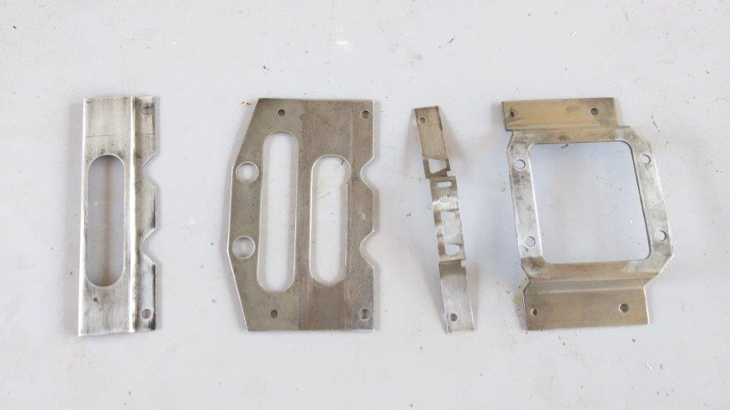
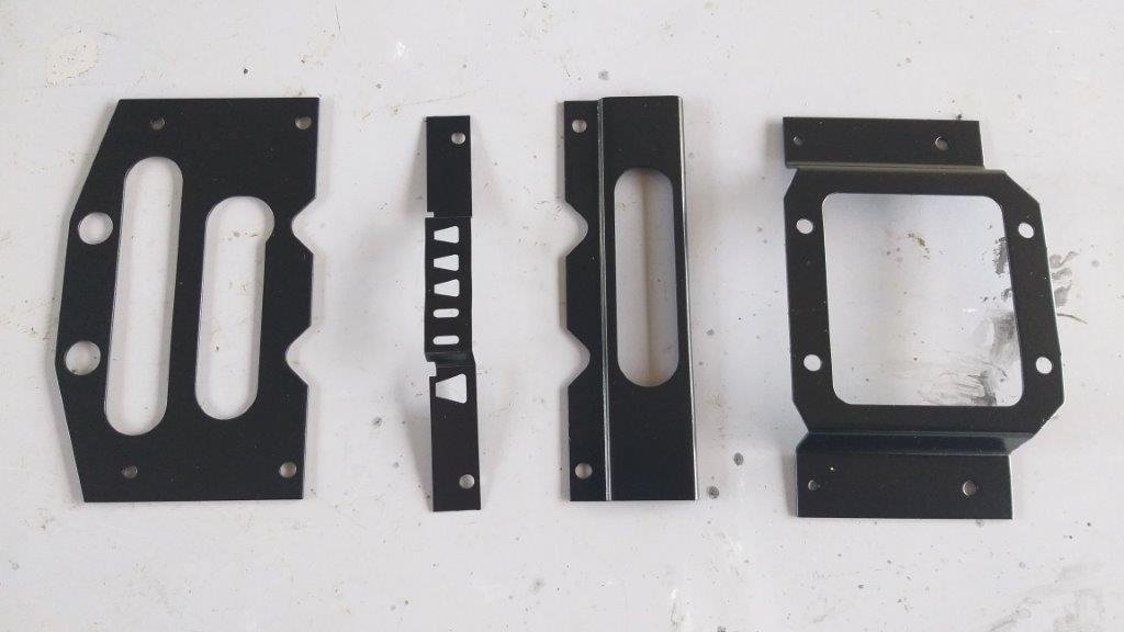
It was getting to the point where I really needed to sort some brackets for various things in order to progress. I normally don't like making them, they are like workshop admin but this time I used Fusion 360 and it made for a much more satisfying experience. First up was the ecu, a smooth thin box with no mounting features so it needed something to hold it securely. I'd heard a local library does 3d printing for the cost of the filament used so thought I'd give it a go. $10.90 later and I have this, black would be better but this is a good start. I just need to cut an ally strip to hold the ecu in place. This will attach to a larger bracket, still in the works, which will also hold the surge tank and oil cooler bracket. Next up were some brackets to hold the starter solenoid and bike fuse box, cad'd up then a template printed to scale and cut out of some mild steel sheet. Lastly is the gear lever bracket, rough cardboard templates first then drawn up in CAD then printed scale templates and test fitted then sent for laser cutting. Brackets11 points
-
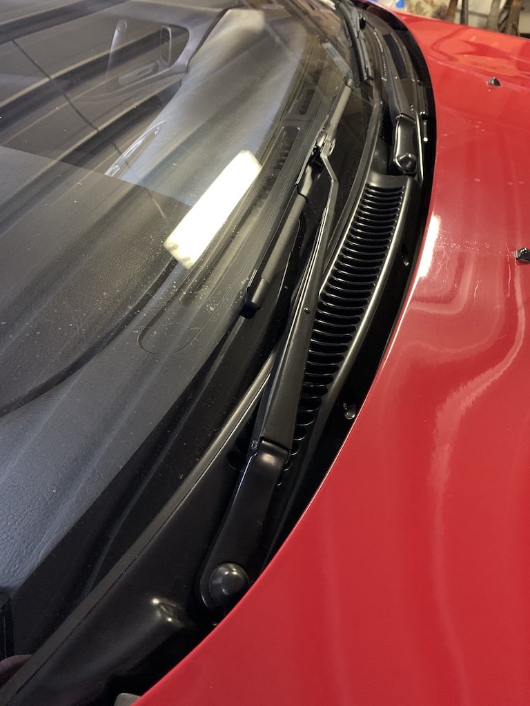
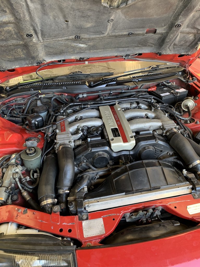
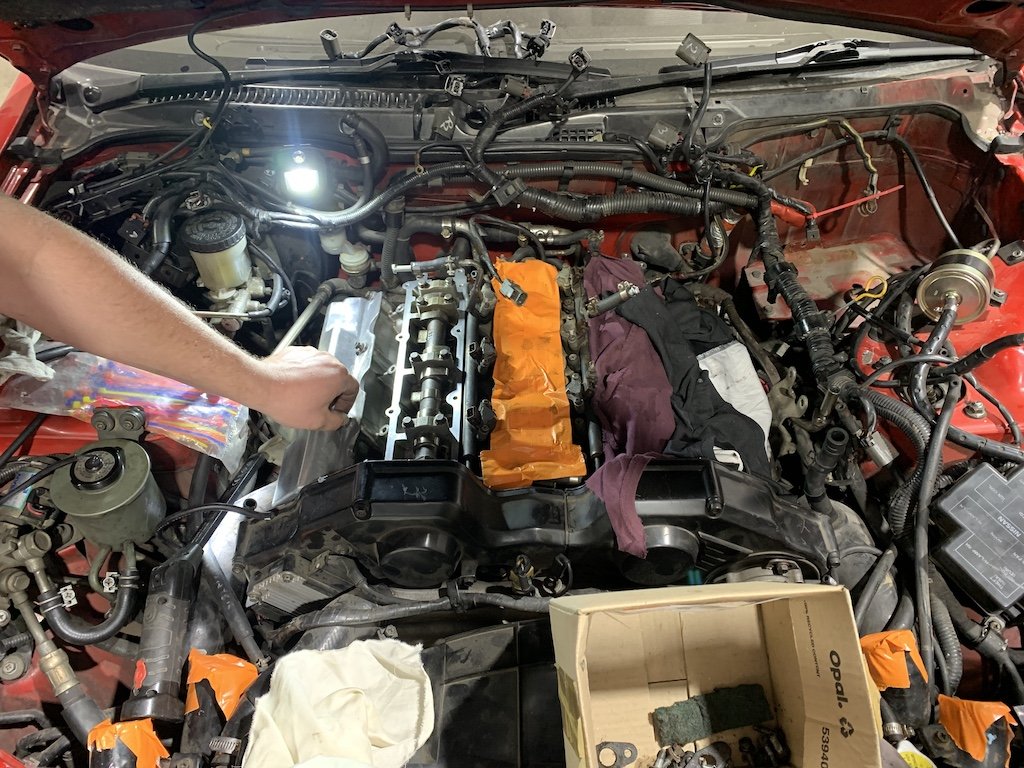
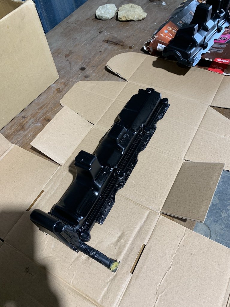
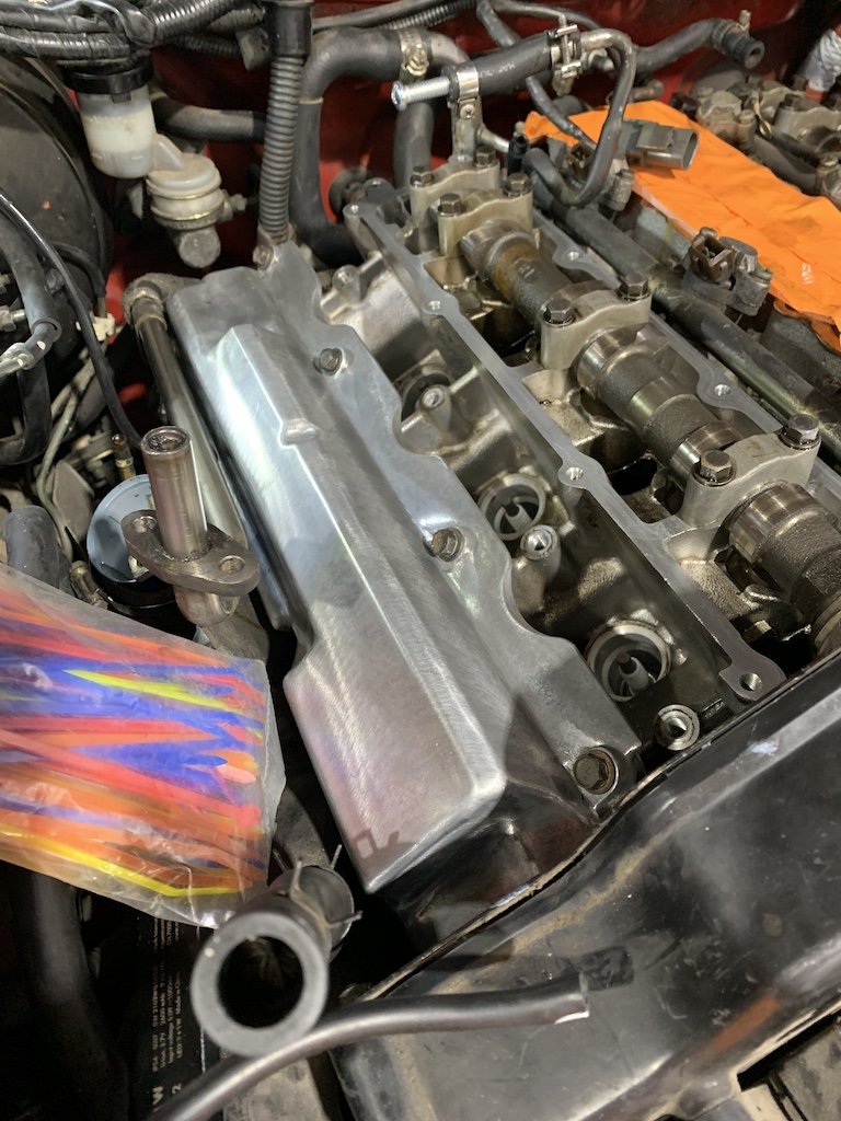
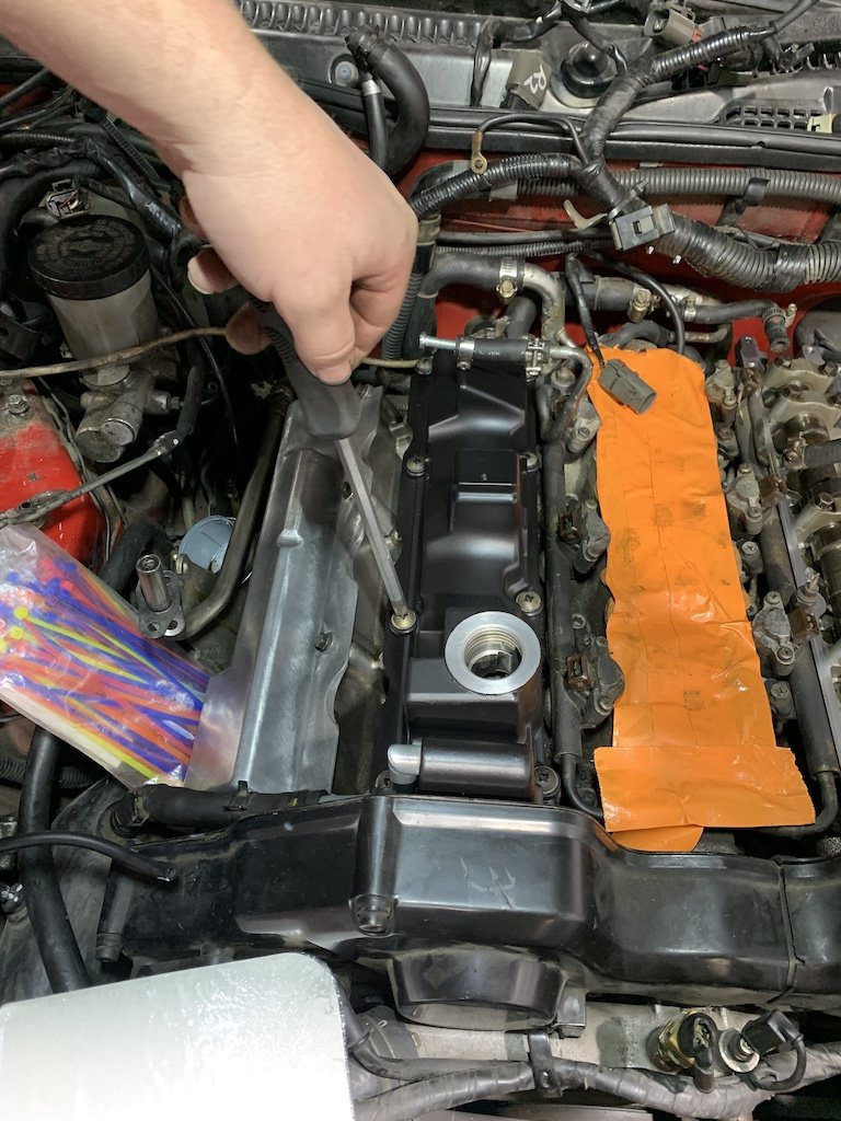
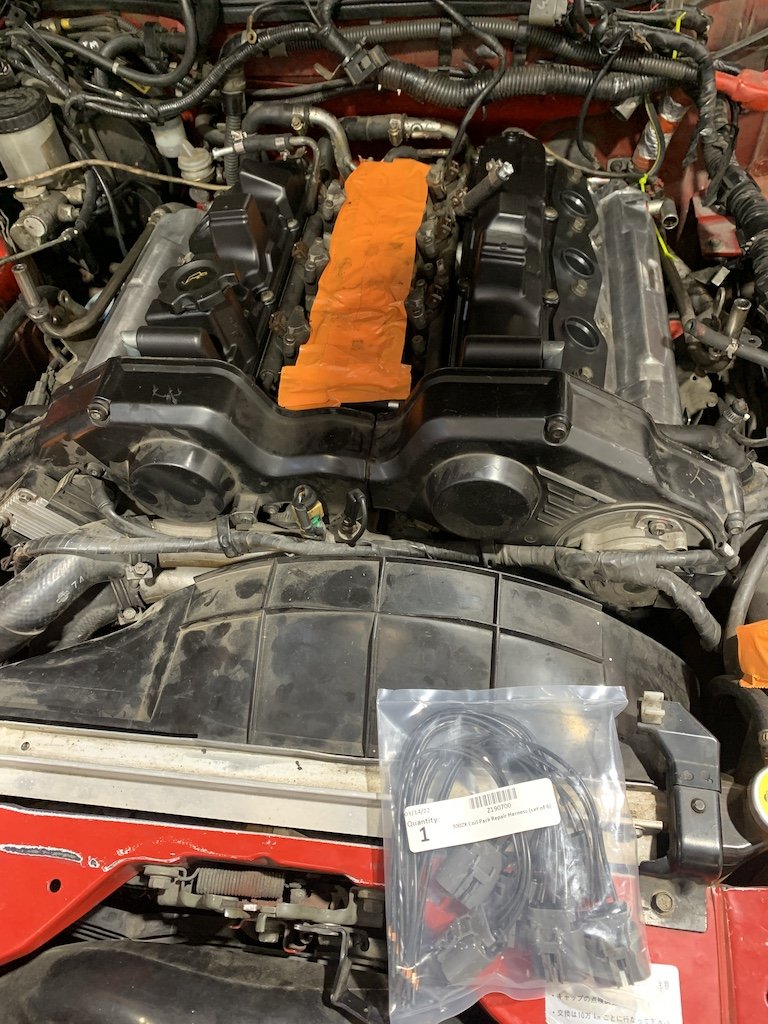
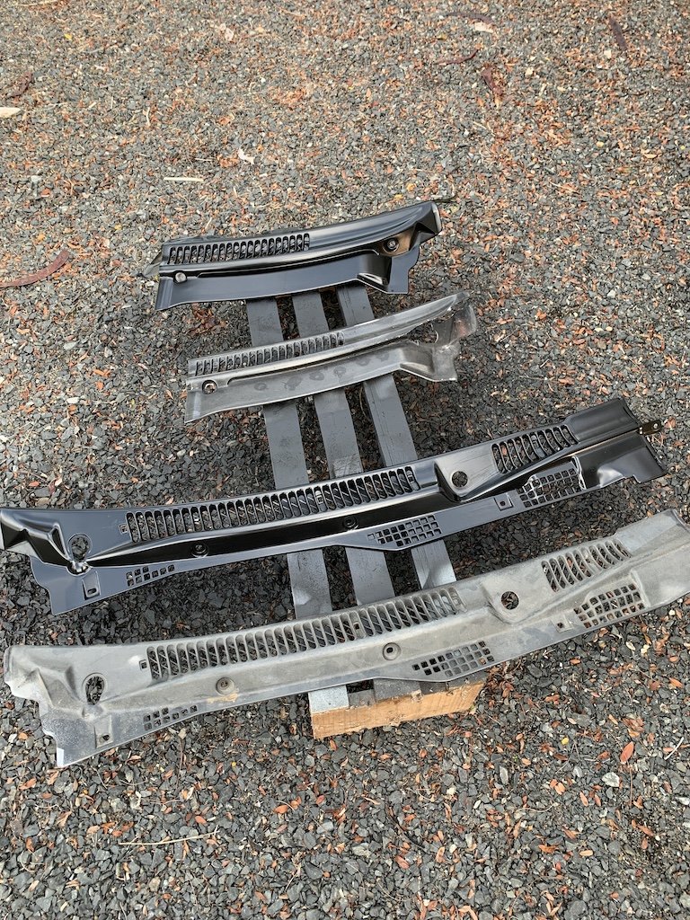
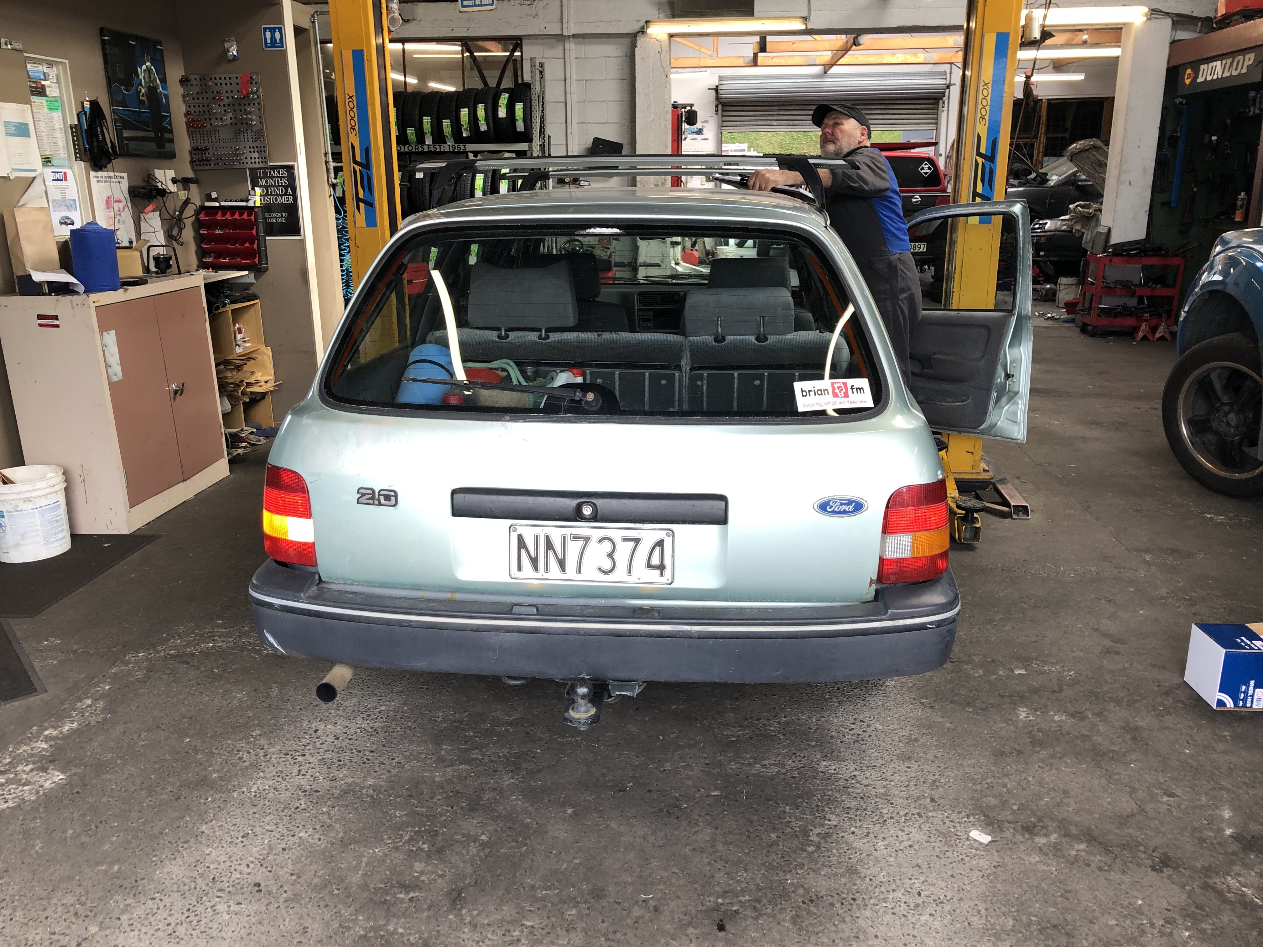
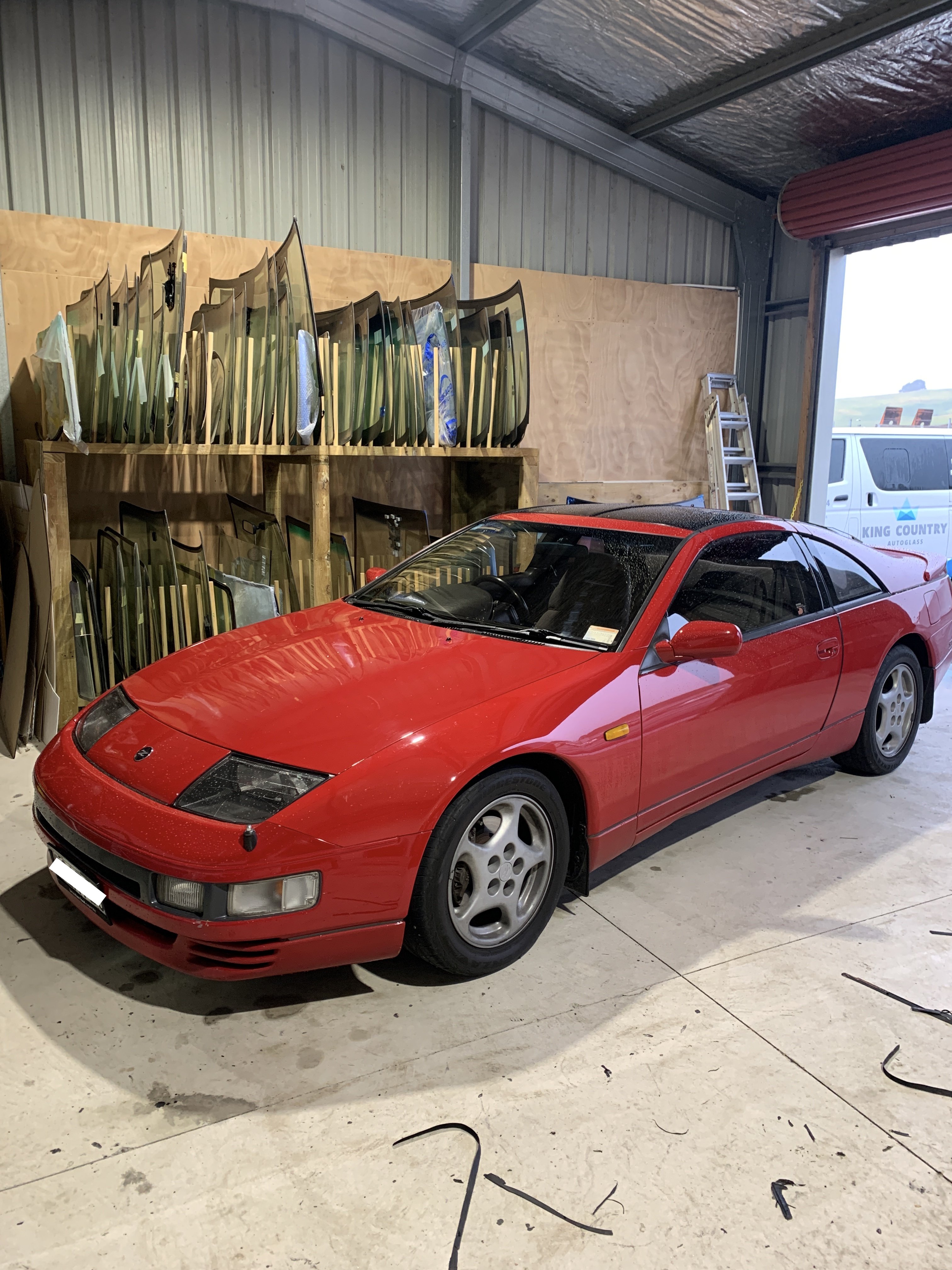
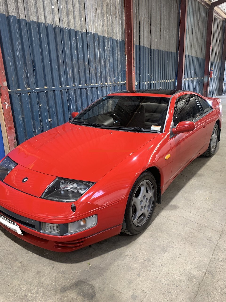
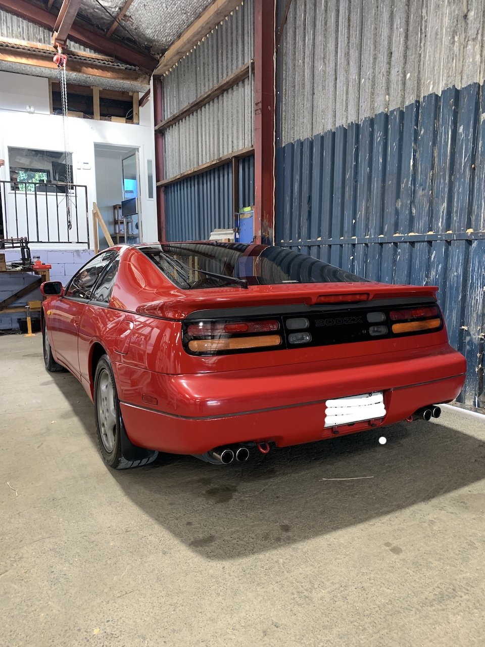
Months go by...... Car went to my mates workshop to replace the rocker cover gaskets, ignition plugs, Japanese manifold heater lines delete, and a few other bits and pieces. It sat there for months, getting a little progress, but between his fucked back, no staff, covid, workshop floods, roller doors falling off, trees over driveways........ it never got finished. So I took it to the local Nissan to finish up. New Wof and ready to go now. Gave the cam covers a clean up. These cars came with a heating system to keep the manifold warm in colder Japanese climates so we took the opportunity to delete these - thought about deleting the EGR too but left if just to avoid any future hassles. Tidied up the cowel panel and wipers and got it back to the workshop, but not after one other small scare....... Once Nissan assembled it all they noted a high idle so I have a new idle control valve on the way, and it had developed a water leak. The turbo coolant hard line had sprung a leak.......removing this means engine out.....FARRRRRRKK. Mechanic was able to sleeve it with some hose for now - so I'm planning a proper engine rebuild/refresh for sometime in the next few years, so until then its cruise and enjoy. Ordered a new radiator too so that'll go in soon, along with some good sounds hopefully. Just waiting for now before getting some wheels. Theres a few rattles and creaks I want to eliminate before I head out for a lower profile tyre.
9 points
-
AE86 updates? I've been ticking away at this but only sporadically as the caravan and the orange EP71 have been eating all my time. Ive been sorting small annoying things like blown dash bulbs, working out why the hand brake/fluid level light didnt work on the dash (wire break), why the dash lights dimmer wasn't working (switch garked up with crud), why the rear brake light warning light was on (incorrect bulb wattage), and sorting small clips and bits of trim that were missing or broken etc. #boring #nomajorprogress But things have been progressing on the other orange EP71: Actually, it might be time to start a seperate thread on this turd...
5 points
-
Another day, another clean WoF.....
5 points
-
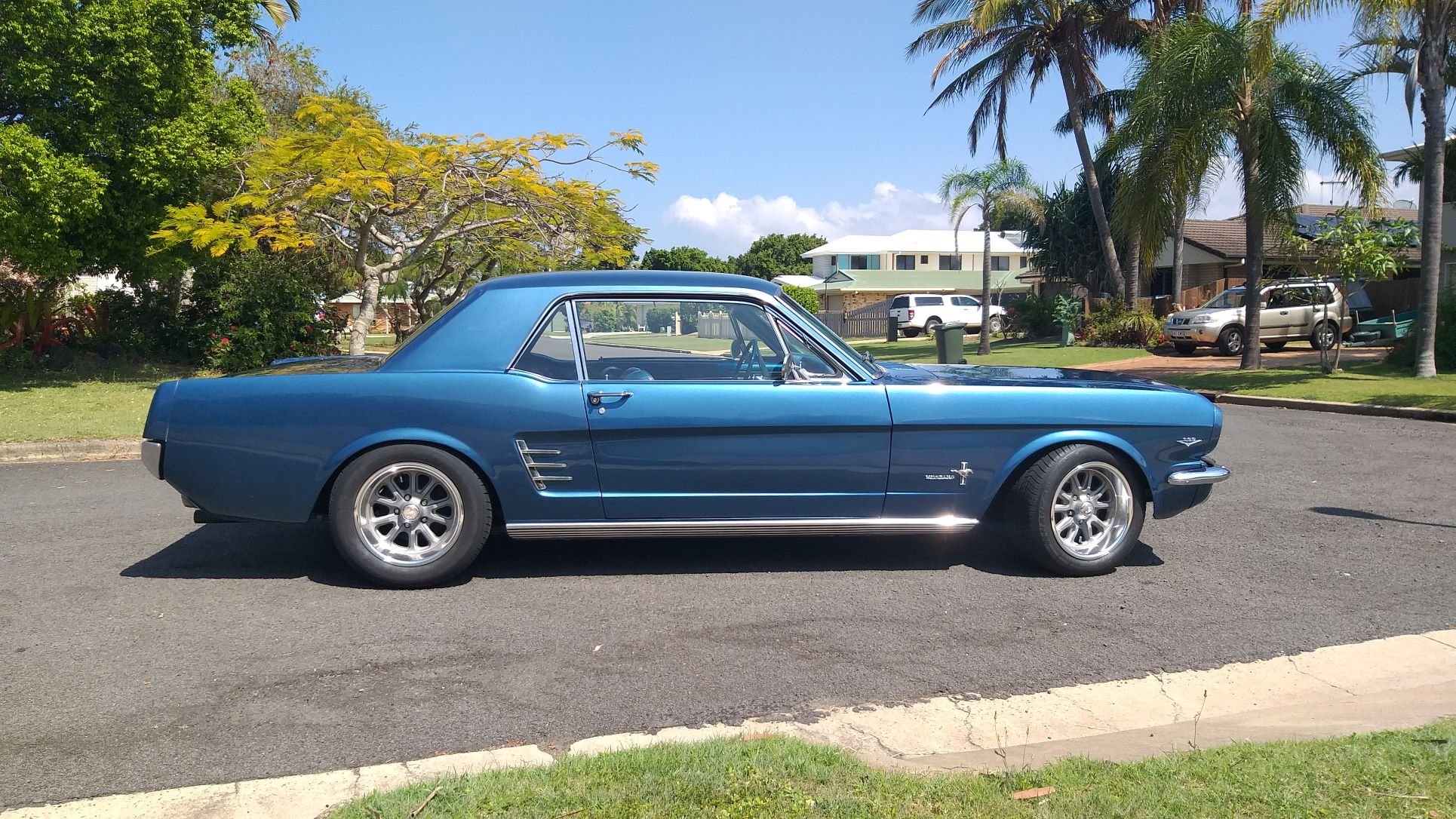
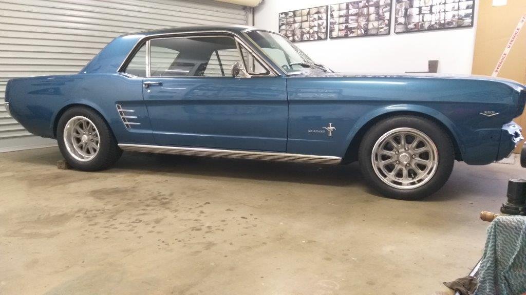
This morning I slapped a bit of Meguiars on the Muzzy. Gave my elbow a bit of a workout and then pulled it out into the sunshine to admire my handiwork. Doesn't look half bad, even if I say so myself.
3 points
-
One thing to factor in when gearing up for co2 mig is you'll need a thread adapter to use a normal argon regulator.. Such as: https://www.trademe.co.nz/a/marketplace/building-renovation/tools/other/listing/3770563324?gclid=CjwKCAjwpqCZBhAbEiwAa7pXeWLObiEjzt92tsZfPaU-opb8YAdYHnlBIL2ZMIdhqGxRwXmBBPNAoRoC-CkQAvD_BwE&gclsrc=aw.ds2 points
-
The Xspurt 1000's appeared to be spraying directly on the very wide port divider killing atomisation and causing it to blow black smoke in higher rev's on the dyno. The factory injectors (and these 3sgte ones) have a nice 4 hole cap which sprays it down the ports at the valves instead of the centre. Using the 3sgte ones made it run better everywhere. Apparently the Xspurts work well on plenty of other engines though. I've had thought about unmodified Bosch injectors since they'd avoid the problem of spray pattern, but it looks like I can get some new genuine 3sgte ones for a decent price which would go straight in and still support 300kw's.2 points
-
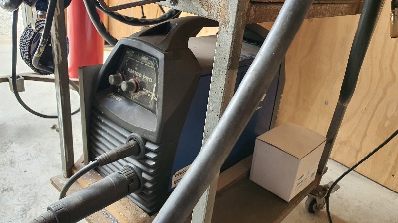
Same here. I bought a 5kg bottle 10 years ago for about $250 and I get it refilled by the fire extinguisher place. 11 years ago the refill was about $35 Its now about $45~50... Apparently/maybe Co2 is less common these days/climate change is a hoax But yeah. I've used argoshield plenty in the past but fuck that cost for mig welding when half the time the welds are probably ground back on car restos or if it's a trailer build then c02 shielded welds are fine. Mig welder I use is a 180amp weldtech invertor from proline also 11 years ago. Goes well.
2 points
-
2 points
-
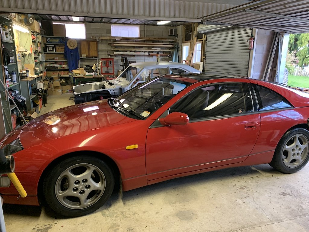
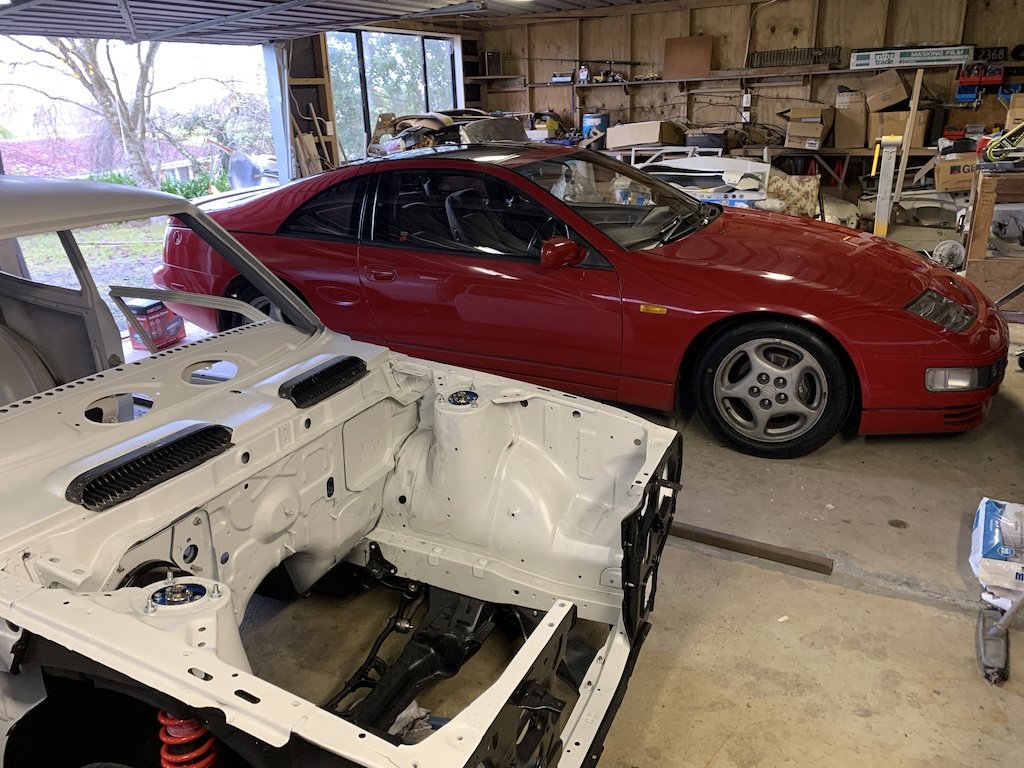
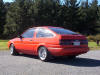
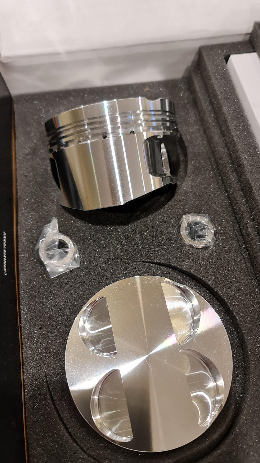
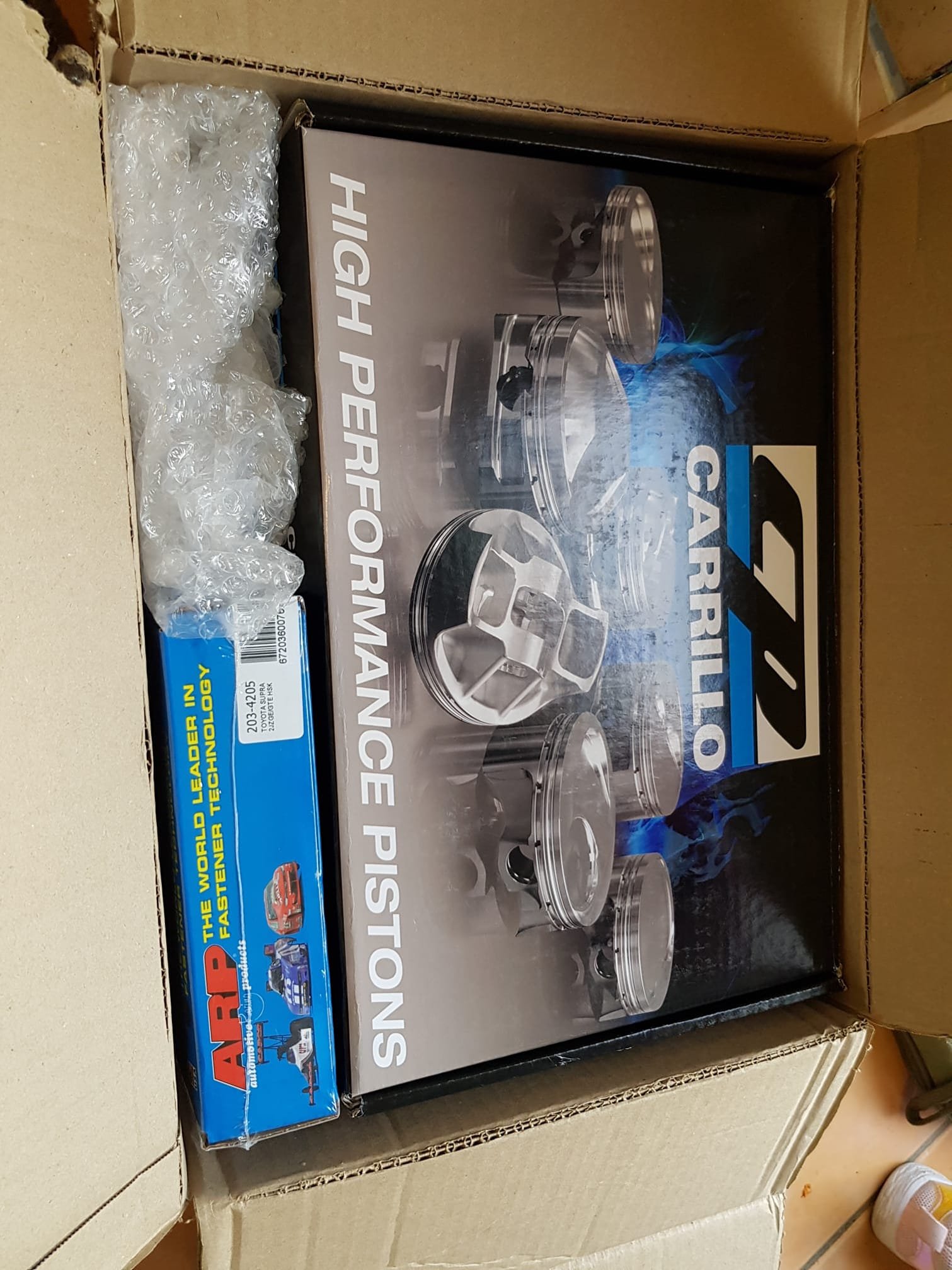
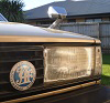
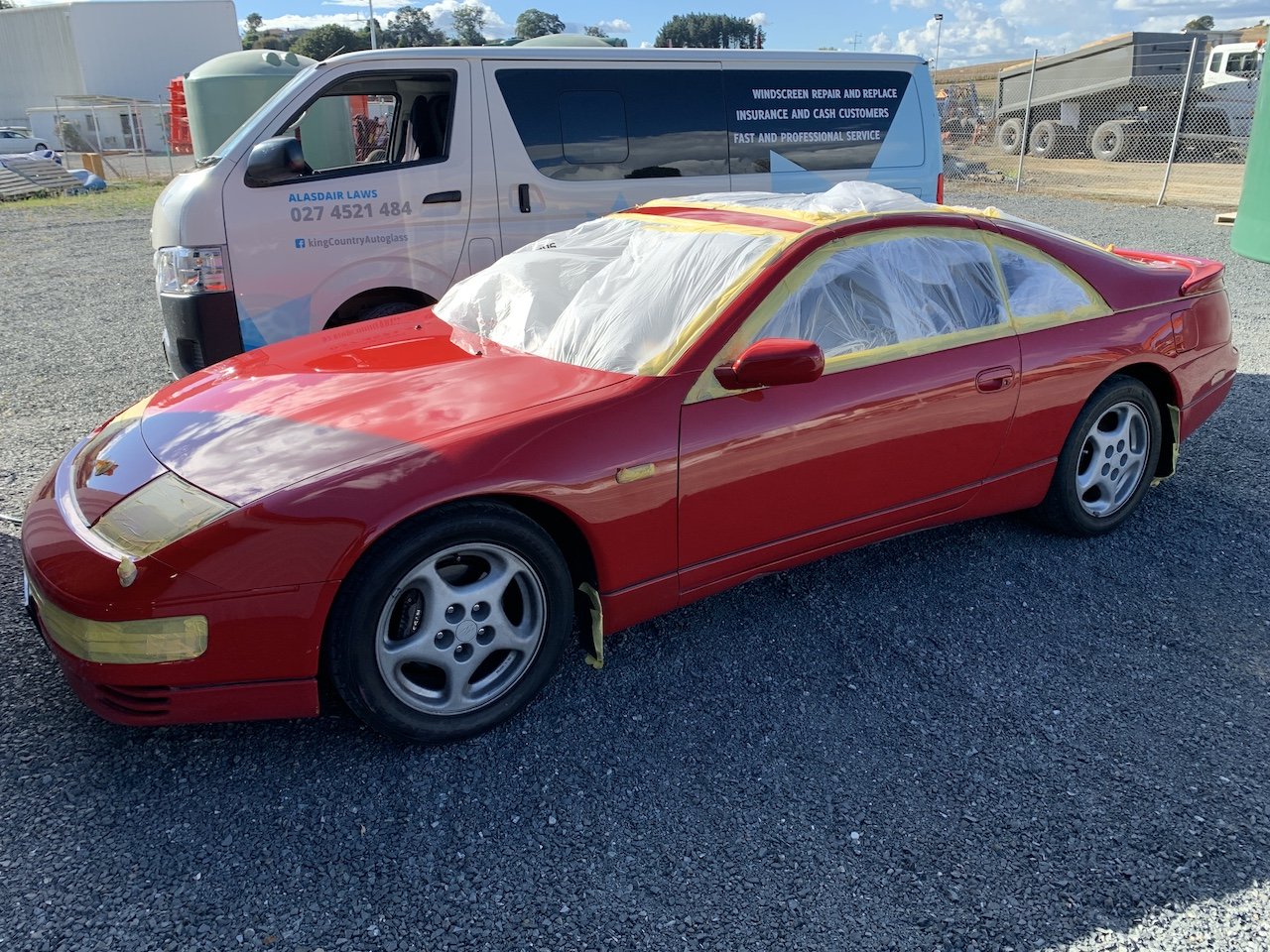
I had pictures of these on my wall as a teen back in the 90's. I never really thought I'd own one - they were considered a sort of 90's Jap supercar. I didn't want another project and started looking for one a few years back but pretty much gave up finding the right one for me. I was looking at Japan but needed 40-50K for that, so started looking at JDM WRX Sti's locally......then this popped up and I had to have it. It's not a mid life crisis car.......It's just a coincidence that I can only afford one now....ok? Red, Twin Turbo, Manual, 2+2, Targa Top - the only this this doesn't have that was on the wish list was the leather interior. I wanted to do a real classy wide body kit like the TwinZ Design ones out of the states, but this has only done 155Kms so will keep any mods simple to maintain the originality for the future. I No doubt it'll cost me some $$ in the future but for now the plans are: Some nice dished/mesh wheels, nice exhaust, tints, stereo, cut and polish, few service requirements and small things.....and enjoy! Foam with me here.....
1 point
-
Well 2 injectors tested 8% and 10% lower than the other 4. One of those was on the melted number 4, so that has to be the cause. Spray pattern is good, but flowing less. Still doesn't explain the low load misfire behaviour . They are 3sgte 550cc injectors from a Caldina GTT, well two sets. Both used. Weirdly, it was noted that the plastic housing is starting to crack on some of them where the coil is inside the injector. Whether this is the problem, I don't know, it's like they got hot. I think one set of injectors has had a hard life previously because the actual colouring of the plastic is faded. I still have the Xspurt injectors but they didn't work well on this engine. The factory pintle cap with 4 holes divides the spray pattern properly and worked much better. So I think I will try get some brand new 3sgte ones, it is tempting to go for a different brand of aftermarket ones but they all seem to be decapped so will be like firehoses just like the Xspurts.1 point
-
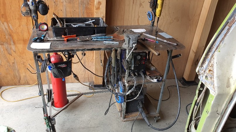
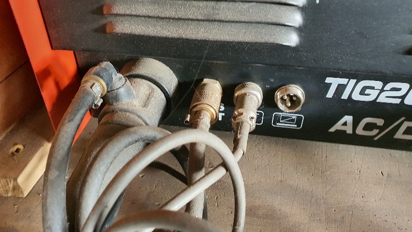
Your welder looks very similar to my Jasic (good old welders) so here's a pick of my set up that might help you?
1 point
-
Any way
1 point
-
If it's registered in nz prior to 2010, no cat required If it's post 2010 it gets complicated1 point
-
Got the Ardunio plugged into laptop, loaded up the programming software, and can now make a LED blink at various speeds. Rekon im almost finished!1 point
-
I run an owner bottle 5kg of co2 on my mig, goes hard for what it is.1 point
-
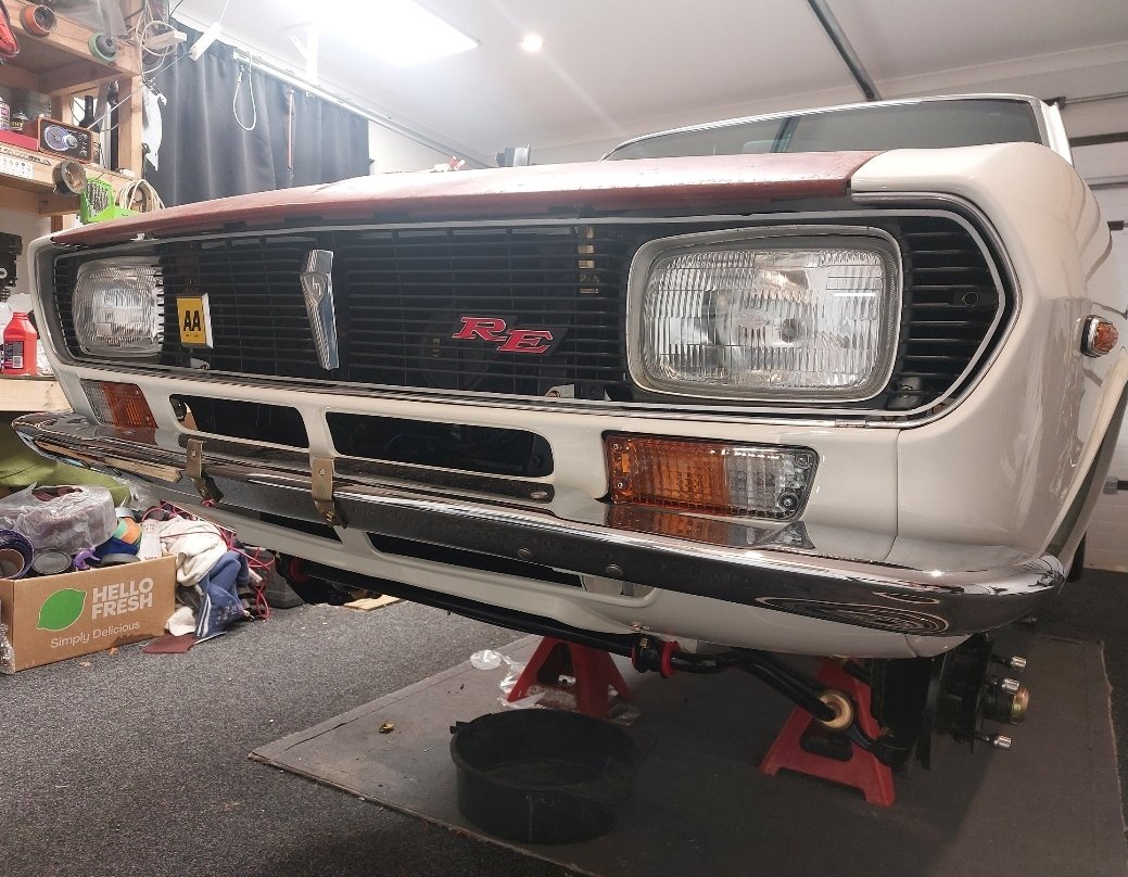
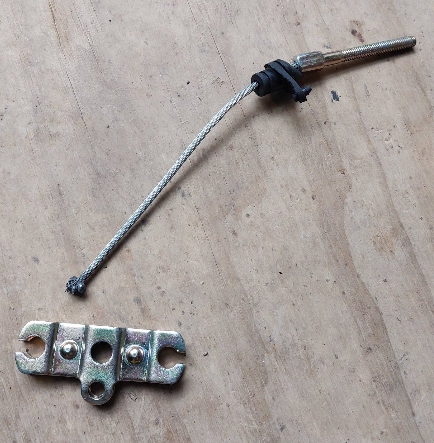
Keeping with the 2 steps forwards, one back theme- have fitted the grille and new badges including a NOS AA badge , have horn working properly now, brakes way better but pedal a touch soft., and then...... my new handbrake cable snapped- God damn this car is fighting me the whole way.
1 point
-
Reducing the OD at the top is more likely IMO to have a piece break out. I'd bite the bullet and replace the guide. Qualifying that, I'll say I've made and fitted a shitload of bike valve guides - and a few car engines too.1 point
-
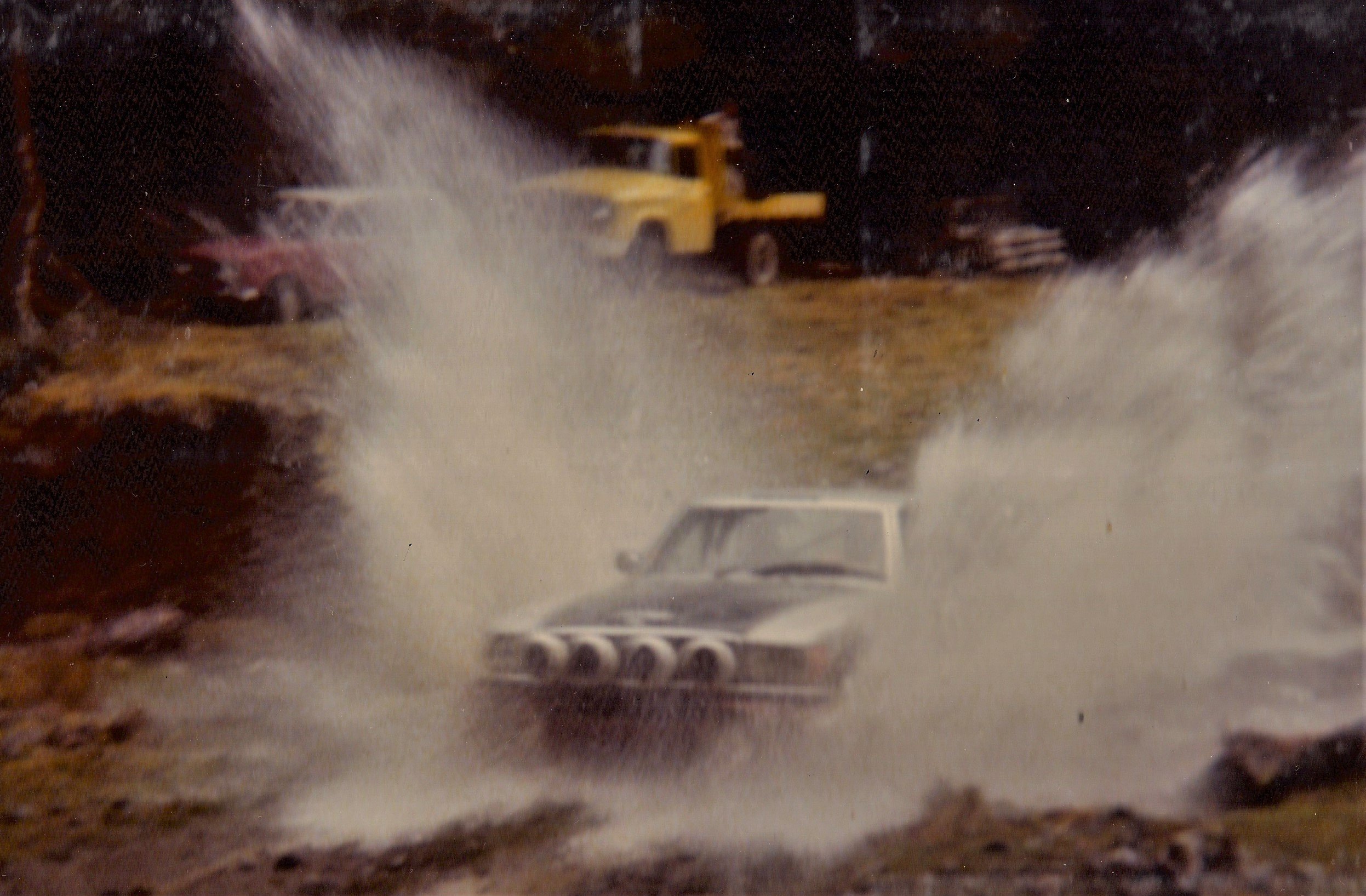
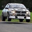
Been a long time since I have been to the Braeburn and Matakitaki, I did quite a bit of clear felling under the new transmission line we were building through their and it was the roads used in the last NZ International Rally to be run in the South Island, we sat on the Inter 4x4 and watched them them going through. . I am keen on this one, might have to find some dual purpose style tires for one of my 150's. I also have a Holden Ute with a towbar if needed for backup although the LS1 will chew through a bit of juice.
1 point
-
I should have also said, I took the car for a quick run around the (private, closed and in Mexico) block to get it up to temp and see how it drove after the work I did previously (fixing air leaks, replacing AFM, and binning the restrictive air filter). The car takes a few cranks to build fuel pressure when cold but starts and settles into a nice idle easy enough. Throttle is responsive even when cold, which makes a huge change. The biggest difference is that the car has gained about twice the power it previously had. Its responsive and can actually haul itself down the road at some pace now. Some lifter clattering was present on the cold start, but otherwise was not present during driving. I'll touch wood, but maybe the engine is starting to be a bit happier.1 point
-
There's less than one month to go on my 10-year deadline! All of the cabinet's controls are electrically working now, but the control panel is just floating loose with a dodgy mess of wires hanging out of it, waiting to cause short circuits. This weekend I spent time stealing images for the digital photo frame which sits at the back of the cabinet's interior. Because this photo frame is old and inexpensive, its black levels are bad and its resolution is only 480*234. If you resize a portrait image to fit that height limit of 234 pixels, it's only this big: To avoid the photo frame filling the cabinet interior with too much light pollution (even from the "black" background either side of the image), I've turned down the backlight and brightness settings. This means that vibrant pop art images look the best, particularly if I can crop them a bit to suit the widescreen format and crappy resolution. Also this weekend, I made the spotlights for the motorised curtain fade out smoothly when switched off, and I hooked up a red/green illuminated pushbutton switch to operate the linear actuator for the control panel. This switch is going to trigger the control panel to rise up automatically when you open the top lid of the radiogram. Even better, it's also going to provide users (me) with endless "light goes on... light goes off" fun by allowing manual raise/lower control. Fails: To implement the control panel's master key switch, I used some dodgy worn-out relays which I saved from the bin at work perhaps 15 years ago. One of them should have stayed in the bin - it has burned contacts, so it fails to switch on more often than not. You end up cranking the key repeatedly to get the 12V accessories to start, as though my radiogram is some kind of British car. I accidentally crushed something against one of the circuit boards, which pushed a heatsink over against a capacitor, piercing it. This circuit board was for the main magic eye. Before discovering the fault, I kept trying to switch the eye on, wondering why it was taxing the power supply and getting hot but the eye wouldn't light up. I'm lucky I didn't fry anything. So I have a lot of cable tidying and mechanical assembly still to do, plus some improvements to the case (it needs wheels, and it needs something done about the state of its varnish). The celebratory Absinthe has been purchased, but I don't know whether I'll be drinking it on schedule. Stay tuned for the next exciting instalment of:
1 point
-
Finished tidying up the Lh side loom and snipped off all the unused plugs. Sorted and rewrapped the engine loom too. Spent a bit of time fault finding in the horn circuit. Found a faulty horn relay in engine bay, so got that swapped, mounted the horn behind grill and got that wired. Need to give it a bit of a clean, and the headers/inlet manifold a polish but most things are done engine bay now. Had a little rubbing of the front tyres at full lock during cert check, so ended up raising front about 10-15mm, lowering bumpstop 10mm, and limiting steering. The drop spindles didn't have an adjustable steering stop, so I had to drill and tap them to suit. Might check valve clearances during the week but pretty much ready for the recheck next week now.
1 point
-
@Raizer turned me up a anti doort delete bung And turned/polished up a knob for me Ordered some new front shocks as stock ones are pretty soft. Clearance deal on trademe of 90 for the pair so we'll see how good /bad they are Rears are eye type/same (smaller eye) as the shuttle's so not many aftermarket options available. I'll try and refit my stock springs onto the damper adjustable mugen shocks as I ground the bush to suit the shuttle arm and they fitted the orthia but were miles too low with the lowering springs1 point
-
Cooling Issue - Chapter Three With my driveway idling test completed, I took the Muzzy out on the open road for some spirited driving. Worked things up to maximum temp and took a reading at the thermostat housing .... 200F ..... that's a little too high for my comfort. So, where to start? Well first up I'm going to flush the system. When I removed the heater core for refurbishing it was full of gunk and needed a good flushing, so I'm guessing the rest of the cooling system may be in a similar condition. Next up I'm going to replace the thermostat. I know there is one fitted as I could see it when I pulled the top radiator hose off, but I don't know what it is rated at. From factory the 66 was fitted with a 190F thermostat. The consensus seems to be that these are a tad high and most fit either a 160F or a 180F. I'm leaning towards a 180F as a starter for ten. I've got a new 180F in stock and will fit that after I have flushed the system. Both of these are cheap and easy to accomplish so worth a shot. Longer term I'm leaning towards a radiator upgrade, but I'll discuss this in a little more detail later. Thanks for reading.1 point
-
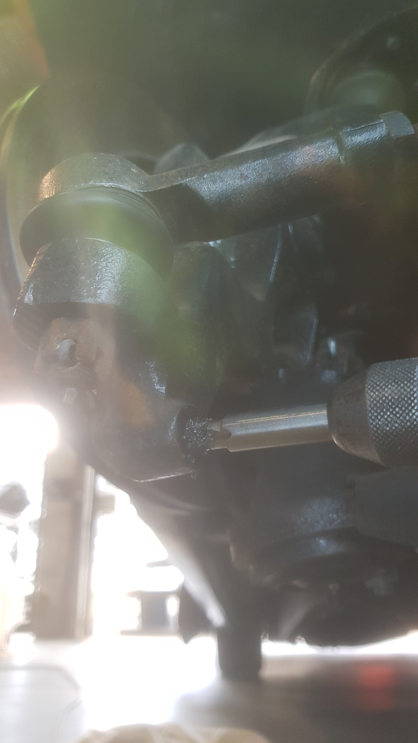
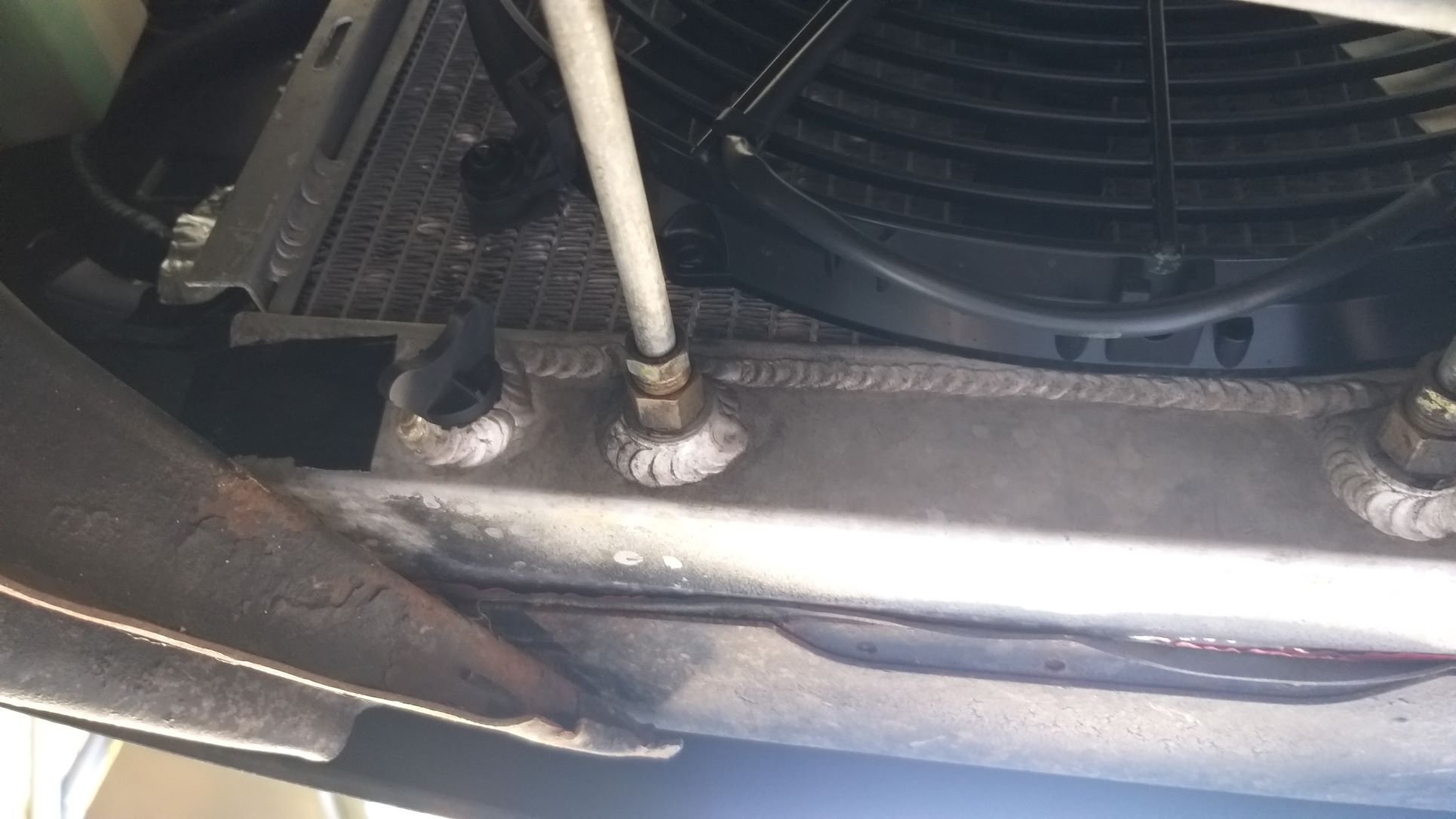
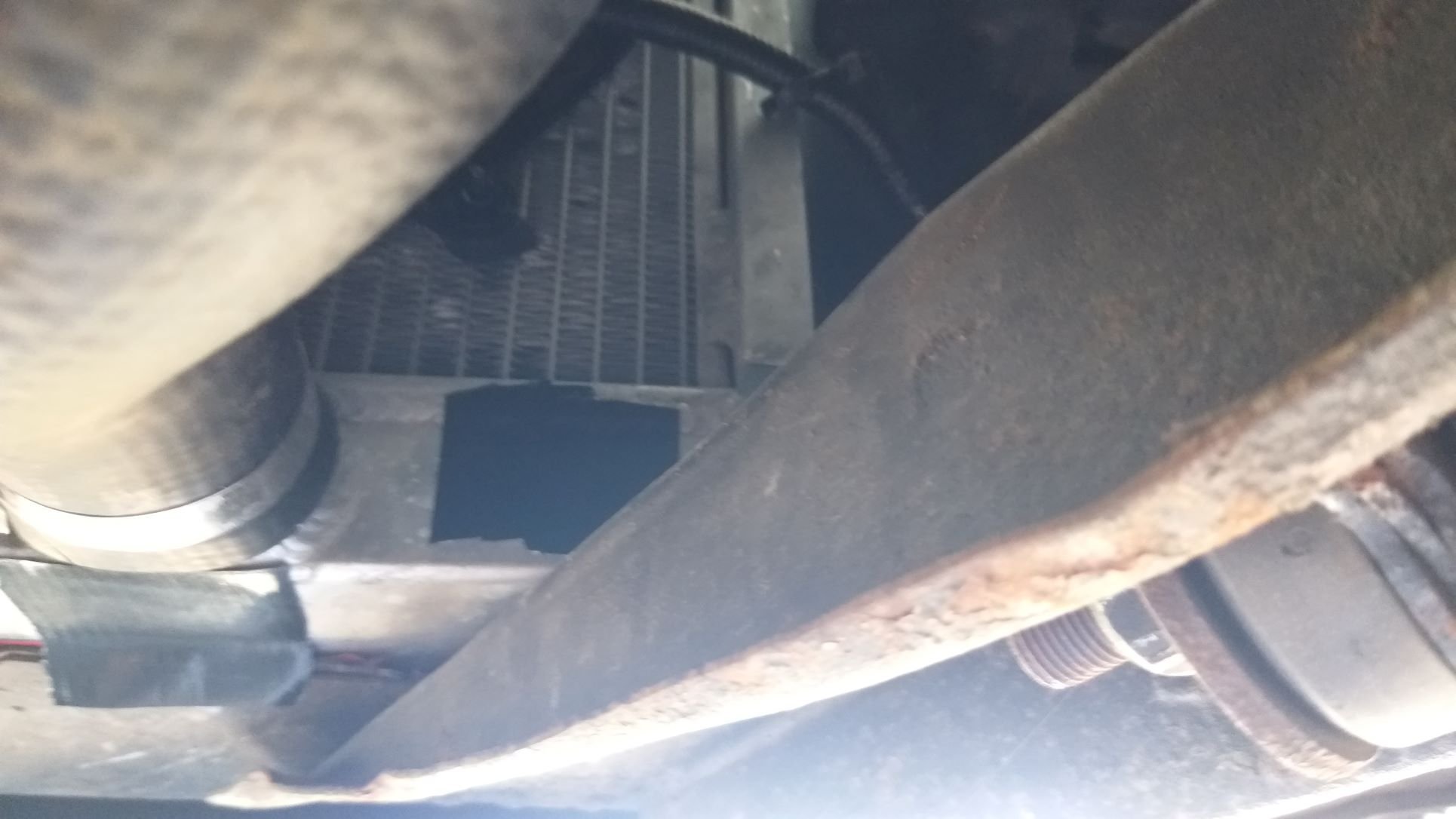
Cooling Issue – Chapter Two So armed with the infrared temp gun and following the advice of @sheepers, I stuck some bits of black tape on my shiny aluminium radiator and started taking some readings. The driveway test revealed that the thermo fan kicks in at around 170F. This measurement was taken directly off the thermo switch that sits in the thermostat housing. At that point the top rad hose measures 160F and the bottom rad hose 140F. The thermo fan cycles on and runs for about 4 minutes before turning off. Idling in the driveway for around 45 minutes the max temp measured was 185F on the top radiator tank. Monitoring the temps at various points on the radiator I’ve been able to establish that the difference in temperature across the top tank differs by about 15F. This supports articles that I have read that criticise Ford for having the radiator inlets and outlets on the same side as they reckon that the coolant ends up taking the path of least resistance and doesn’t utilise the full radiator core to maximum advantage. Some of the more expensive aluminium radiators are fitted with a baffle in the top tank to prevent this but clearly my cheapy radiator doesn’t have one. Apart from the fact that my radiator doesn't have a baffle fitted, I'm relatively comfortable with cooling performance at idle.
1 point
-
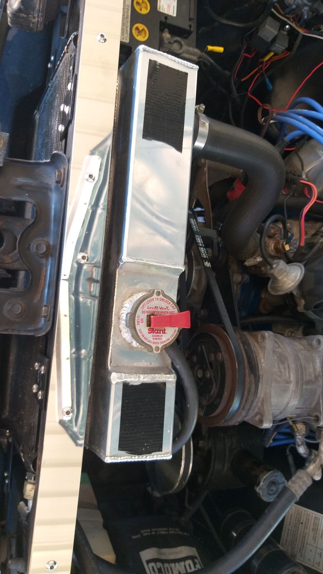
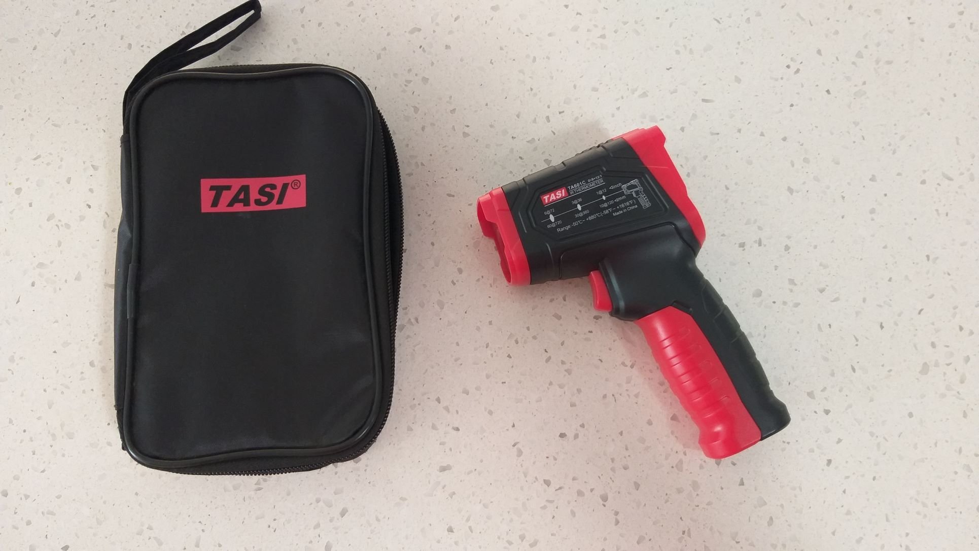
Cooling Issue – Chapter One The next big ticket item on the Mustang “to do” list is to improve the engine cooling. The 65 and 66 Mustangs are notorious for engine cooling issues. The main reason for this is a poorly designed piddly little radiator. Things get even worse when the car is sporting a/c as the condenser is mounted in front of the radiator which doesn’t exactly assist airflow. The boffins at Ford then increased the size of the radiator on the 67 and 68 cars, but cooling was still borderline, especially in the hotter USA states. Eventually Ford changed to an even bigger crossflow radiator in the 70s and this seems to have solved the issue Somewhere along the line my Muzzy has been upgraded to a 3 row aluminium radiator, but I suspect that the previous owner was still battling with temp related issues here in sunny old Queensland as the a/c condenser had been removed and the space filled with a helper thermo pusher fan. So far I’ve made a few changes that have improved things slightly, but I’m still not a happy bunny. First up I removed the cheapy pusher thermo fan as well as the original factory 5 blade mechanical fan and installed a 3000 CFM Spal puller fan on the back of the radiator. I was initially running a radiator shroud and whilst the car would happily idle all day on the driveway with the thermo cycling on and off, out on the open road under spirited driving conditions I noticed a drastic increase in temp. I ended up ditching the shroud and mounting the Spal directly to the radiator and open road temps decreased once again. However, now that I have refitted the a/c condenser in front of the radiator I’m again battling with open road driving temps and I figure I’d best knock this on the head before summer arrives and I get the a/c re-gassed. I’m worried that the warmer days and extra heat dissipating off the a/c condenser might just push the engine temp into the critical zone. So first up I needed to add some science to my investigation. I set my sights on finding something more useful than the factory temp gauge which helpfully has no temp markings. After pesting everyone on the tech forum page and getting some really good advice from the usual old school legends I got my hands on an infrared temp gun. Let the investigation begin:
1 point
-
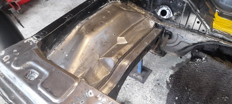
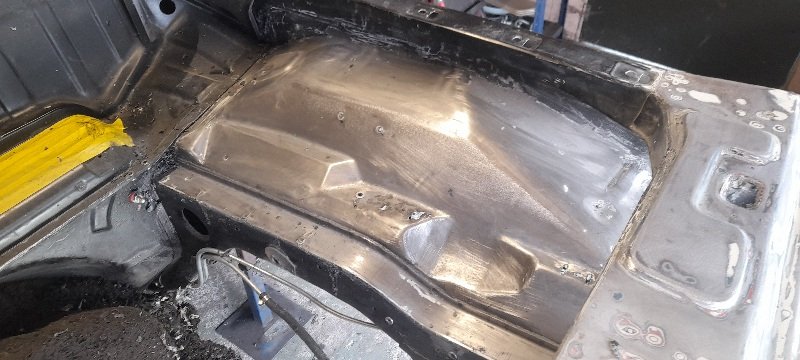
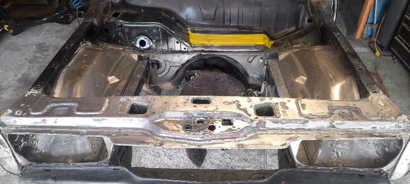
Sweet! It’s not finished but it’s roughed out pretty close. There’s actually not much car left to straighten out which is pretty exciting, I hate bodywork.1 point
-
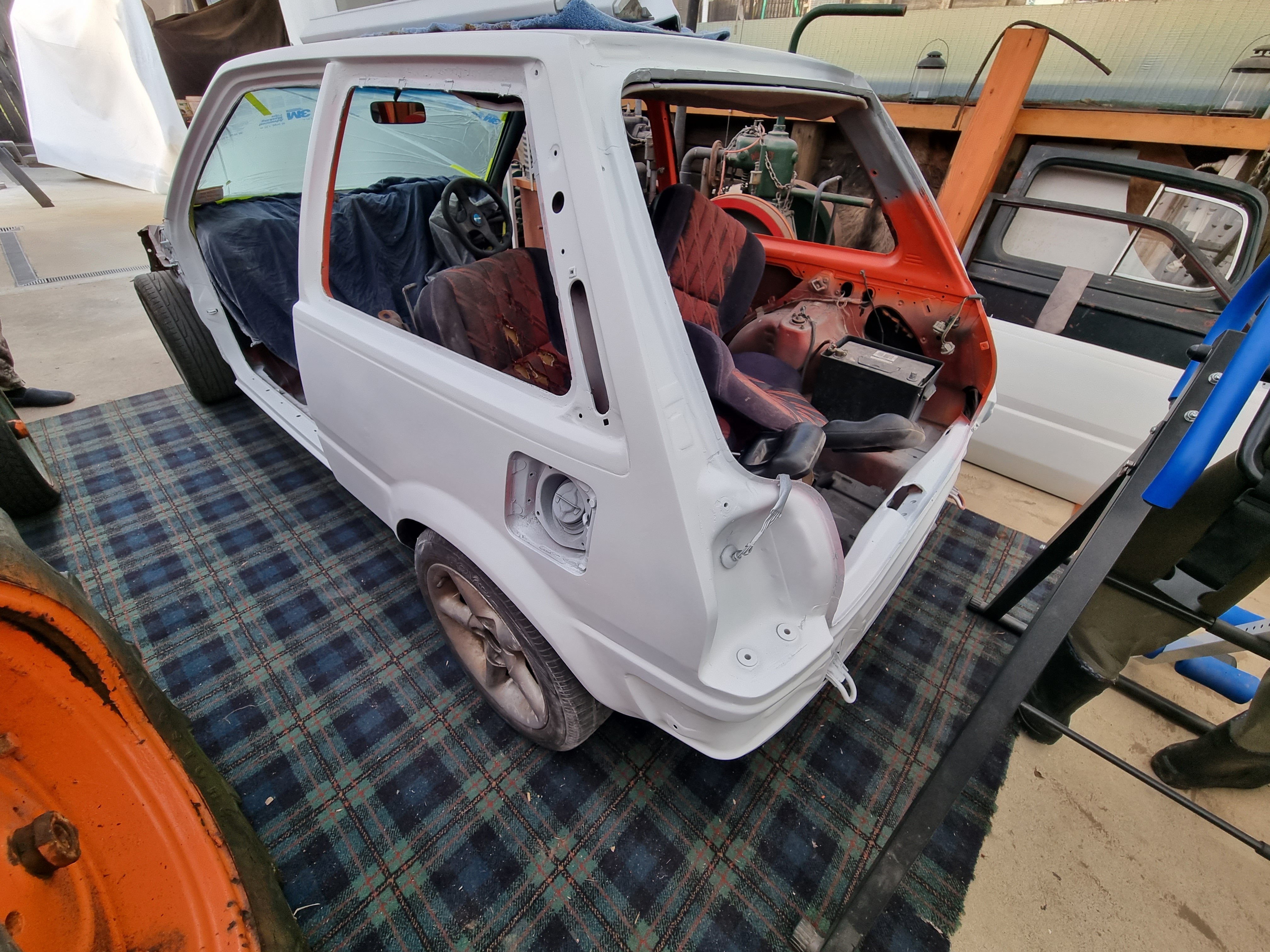
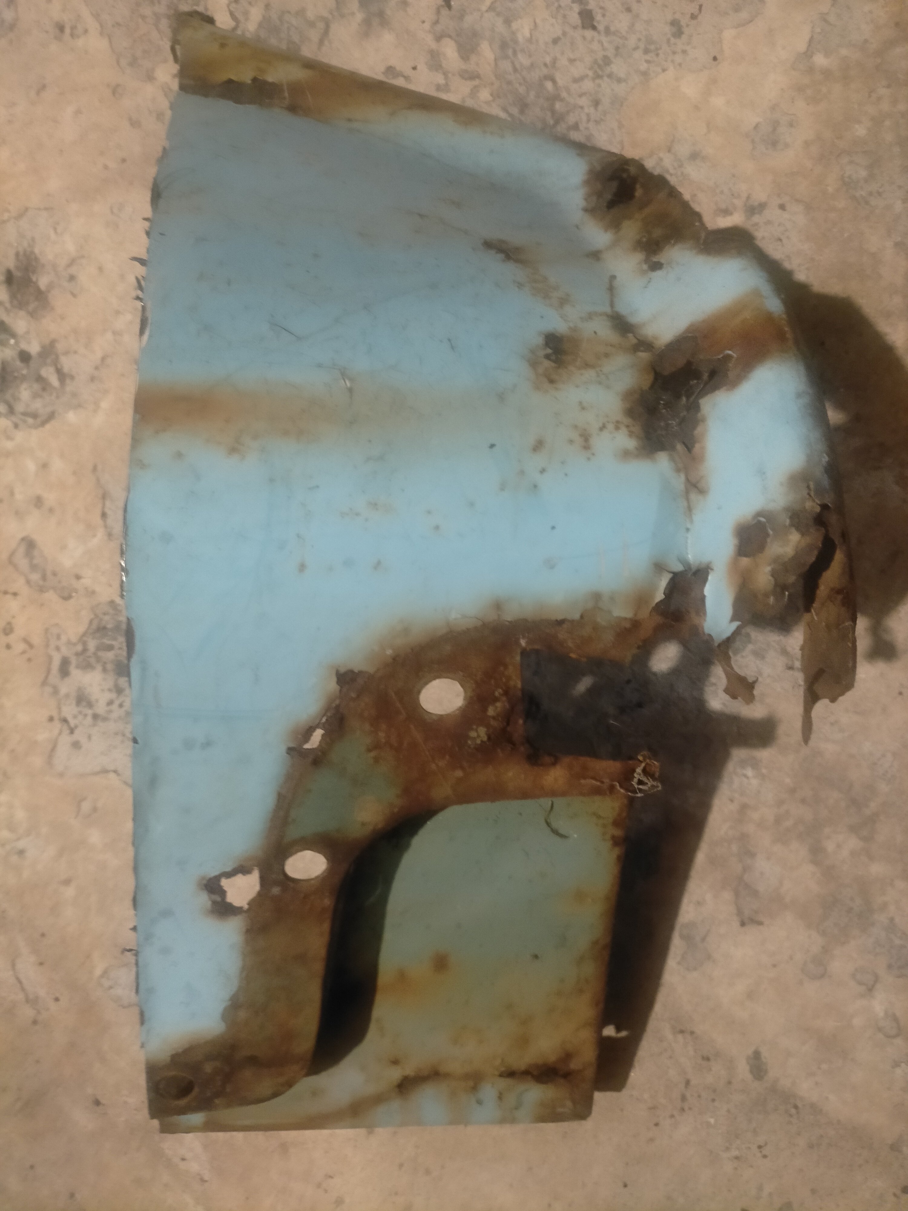
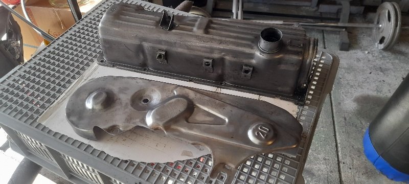
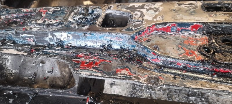
grab a tin of paint stripper yesterday and set to work.. got a spare rocket cover and a cam cover I'll have to modify done. then I started on the engine bay.. there was a few volours on the slam panel.. factory primer ,factory blue ,then red then white primer and finally black.. but not in the engine bay itsself.. I know that it sat in a panel ship for 8 years and they may have done shit as the engine bay was just the white primer and then black... there was some bog over holes..so ill cut some rust out and the go from there but all in all bloody clean... not paint striping the lot as I'm going to spray some areas with underseal.
1 point
-
Why shouldn't you be adjusting the height by moving the whole body? Seems like the logical way to me. Spring perch is only useful to setting preload and the likes.1 point
-
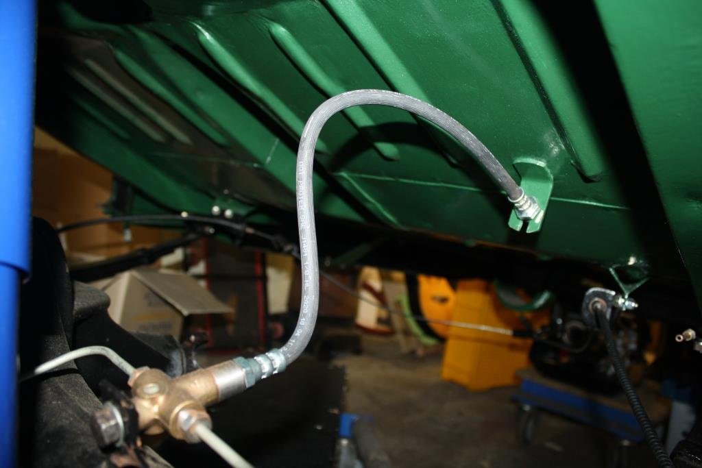
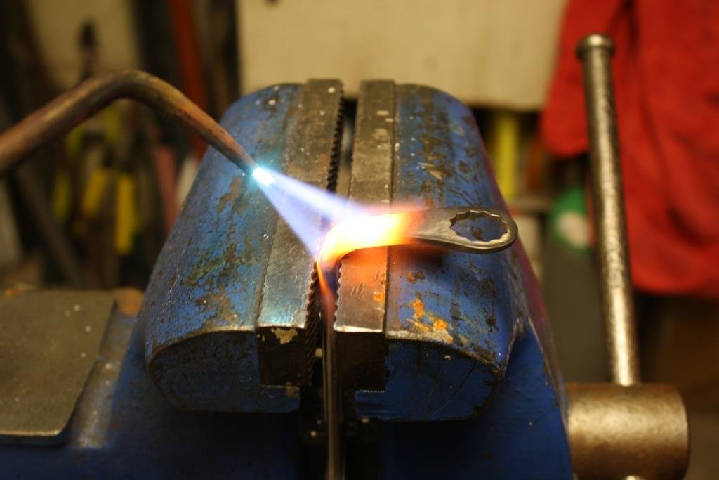
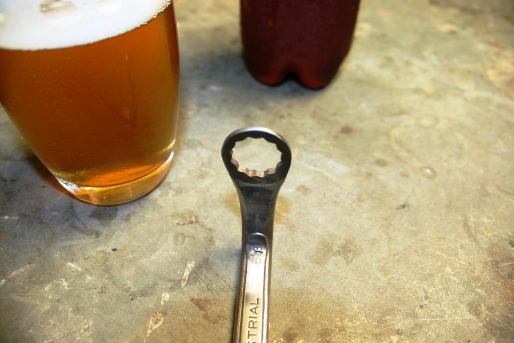
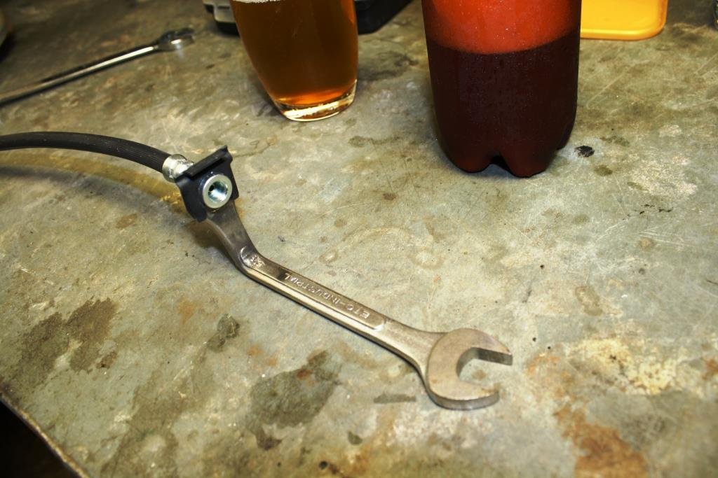
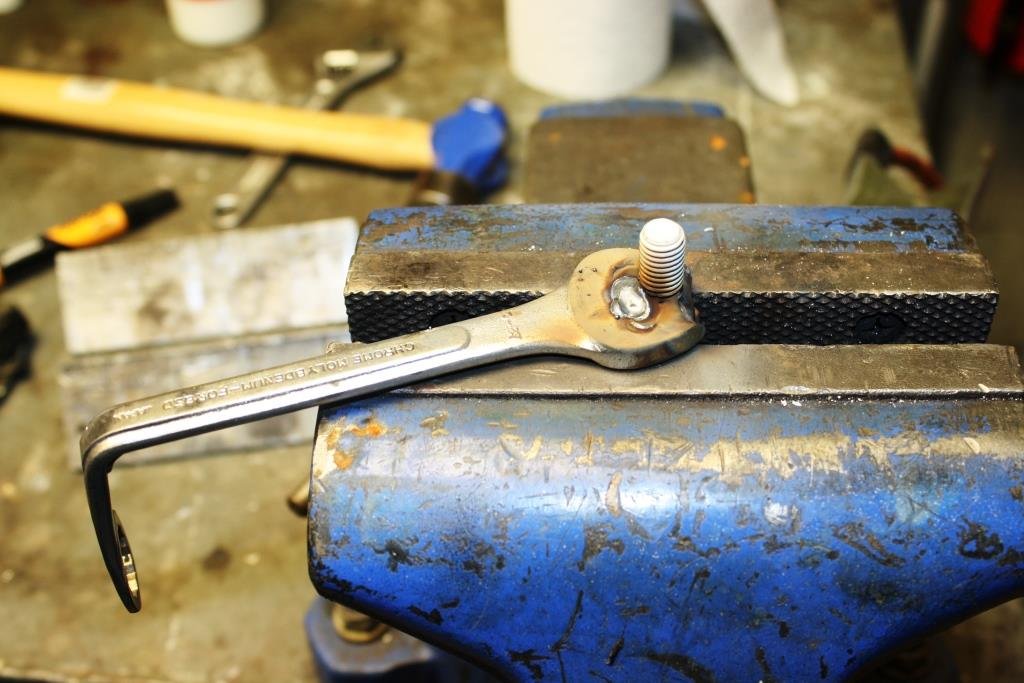
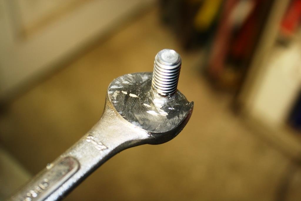
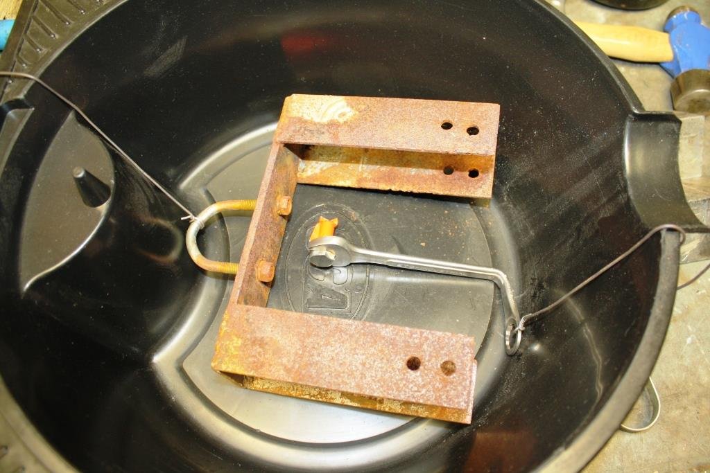
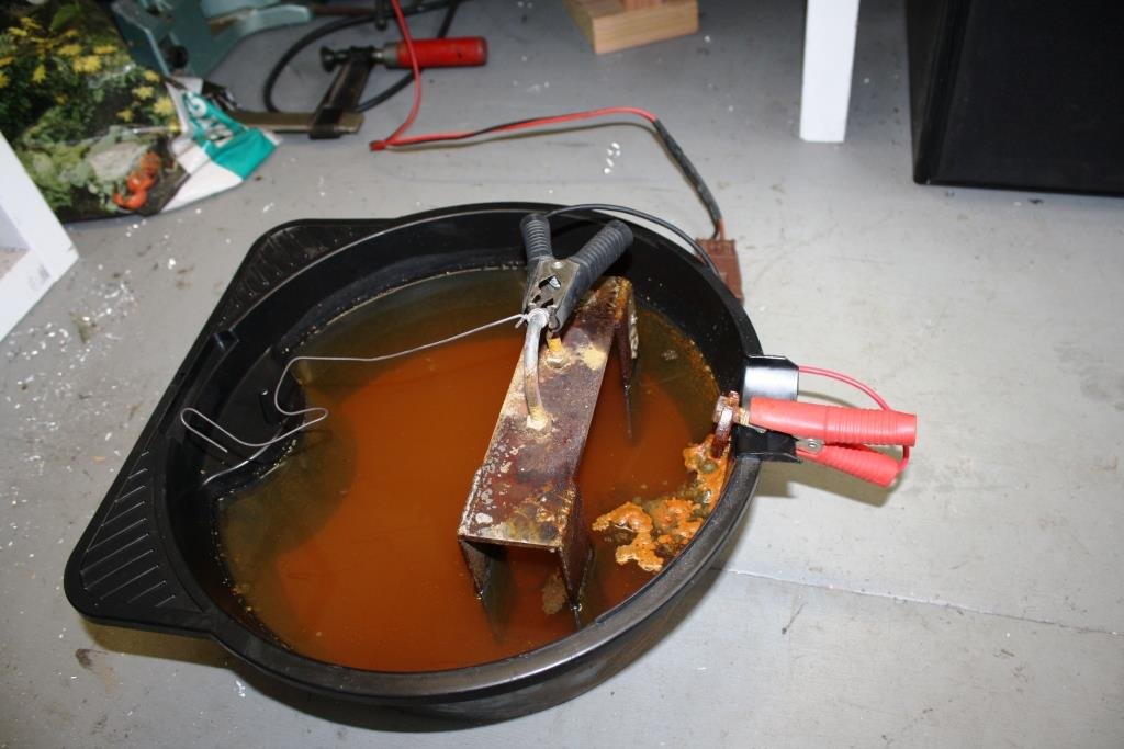
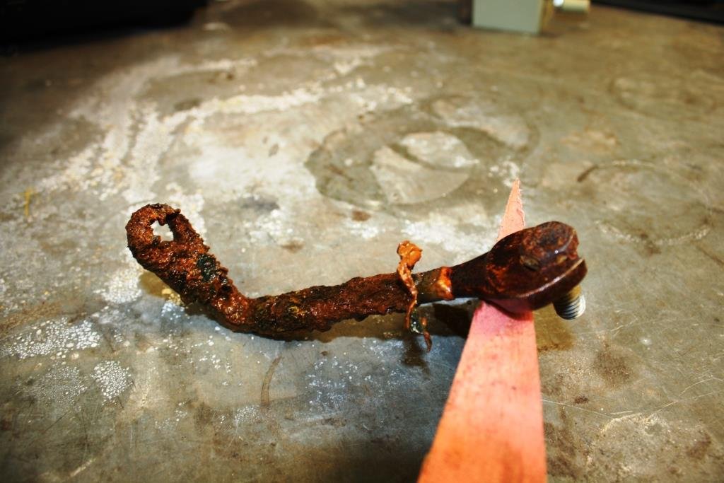
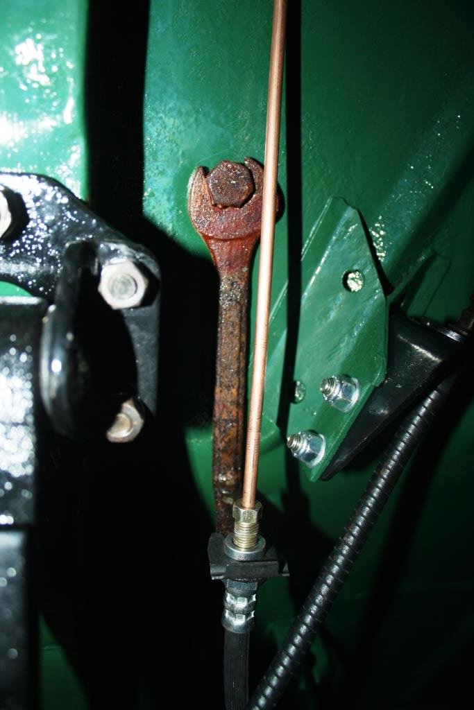
As I’d mentioned earlier I made the call to use HQ brake hoses as I figure they will always be available, (HQ’s are a religion in Aussie!). The problem with using the original rear brake hose mount was the large bend in the hose. One night Rigamortice and I got bored and decided we needed to sample the latest brew and devised a cunning plan…….. What could possibly go wrong? Found an old 5/16 AF ring and open end spanner and applied some heat. Hit the ring end with the linisher to make it a little thinner. A perfect fit for the HQ brake hose. Welded a bolt into the open end… And cleaned it up with the grinder. Started thinking it was all looking a little too shiny…… If you’ve followed this thread you’ll be aware that I’m a big fan of using electrolysis for rust removal, why not use it for rust plating? Found a piece of rusty scrap and made it the cathode, made the spanner up the anode, added some washing soda & water and hooked up a power supply. The following morning we had rust soup and a slightly fuzzy head. And a gloriously rusted spanner. Sealed it with some clear lacquer and bolted it in place. A nice little hidden surprise for the WOF man.
1 point
-
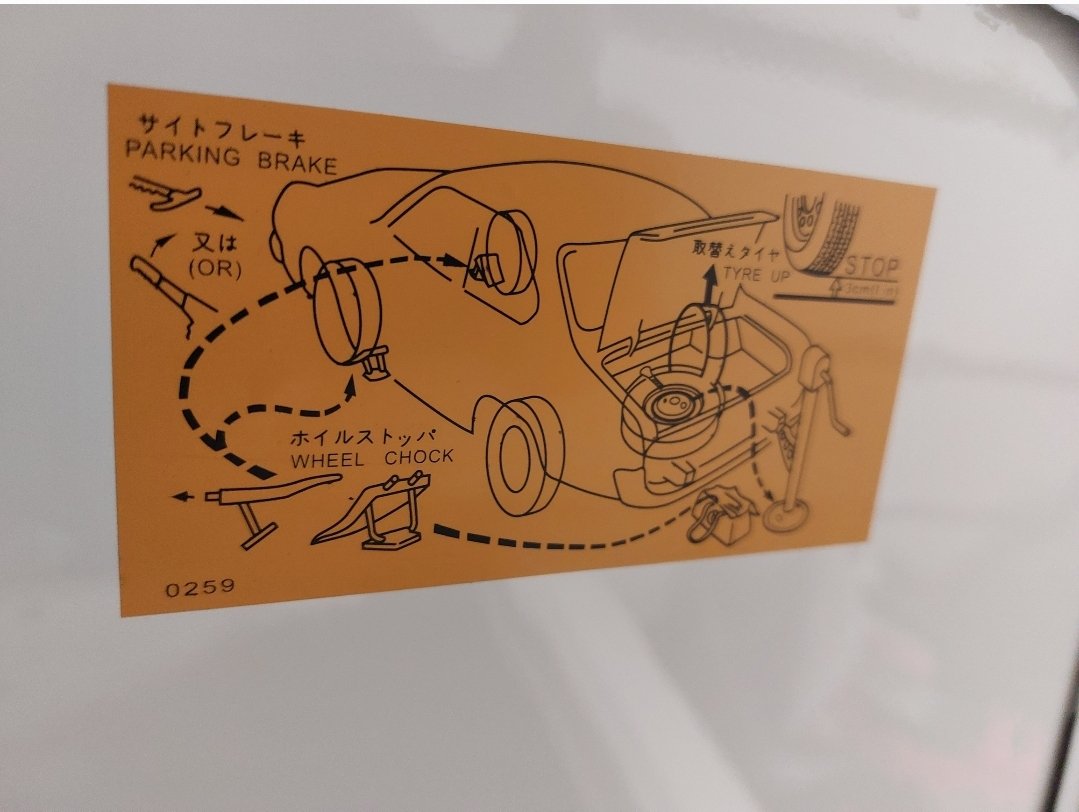
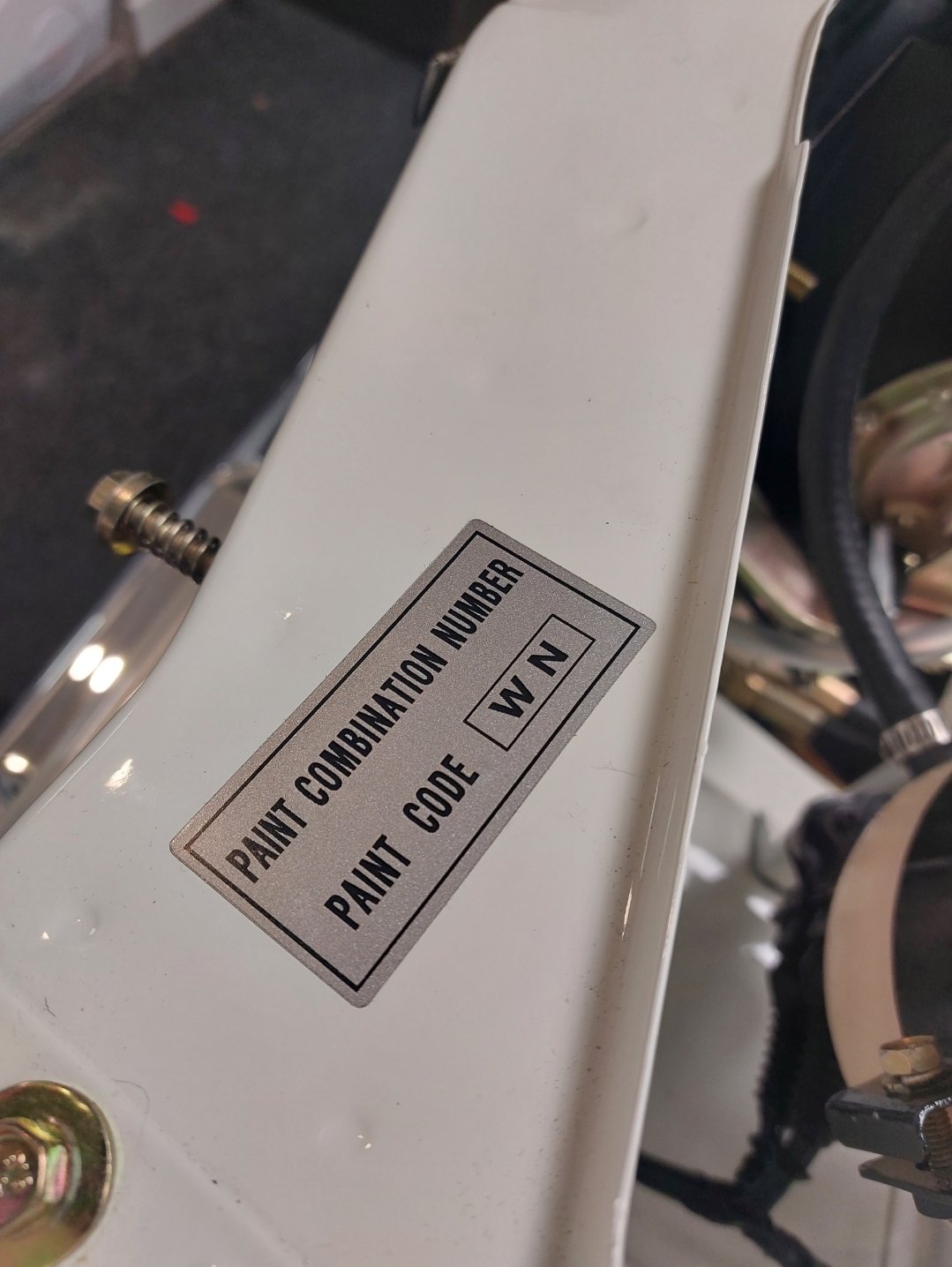
Bought a repro factory sticker kit, there's more here than shown, only a small item, but makes a big difference I think.
1 point
-
Diesel hot water heater is the one shown in this vid. If i was doing a purely hot water setup id do it different, maybe a Webasto or something for pure hot water heating and have a separate air heater. Its a 8kw, and its a bit too powerful for the size of the camper, even on a cold night need to crack a roof vent or it gets a bit toasty. Camper had a propane hot water cyl from Japan, as well as a propane 2 burner cook top, but where the bottle used to be ended up being where the rear seat frames needed to go, and carrying a lpg bottle introduces a few other issues. I think it originally had a generator on a slider in the back left corner too. Ive got the diesel hot water plumbed through the original hot water cyl, has some fancy acutated valves so there is no water in the heater when the pump isnt on so doesnt go festering inside the heat exchanger. Can get cylinder to 60deg in about half an hour, enough to do proper dishes or a quick shower to rinse off. Only has a 85 litre fresh water so showers are brief if need be depending on supply.1 point
-
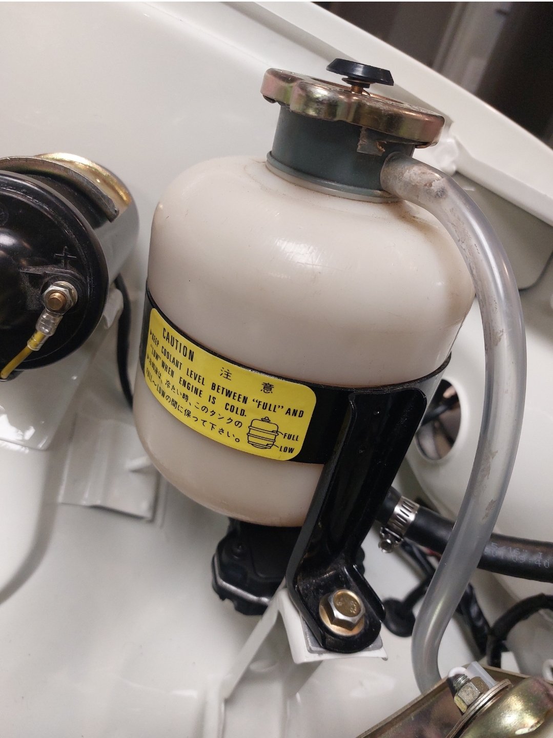
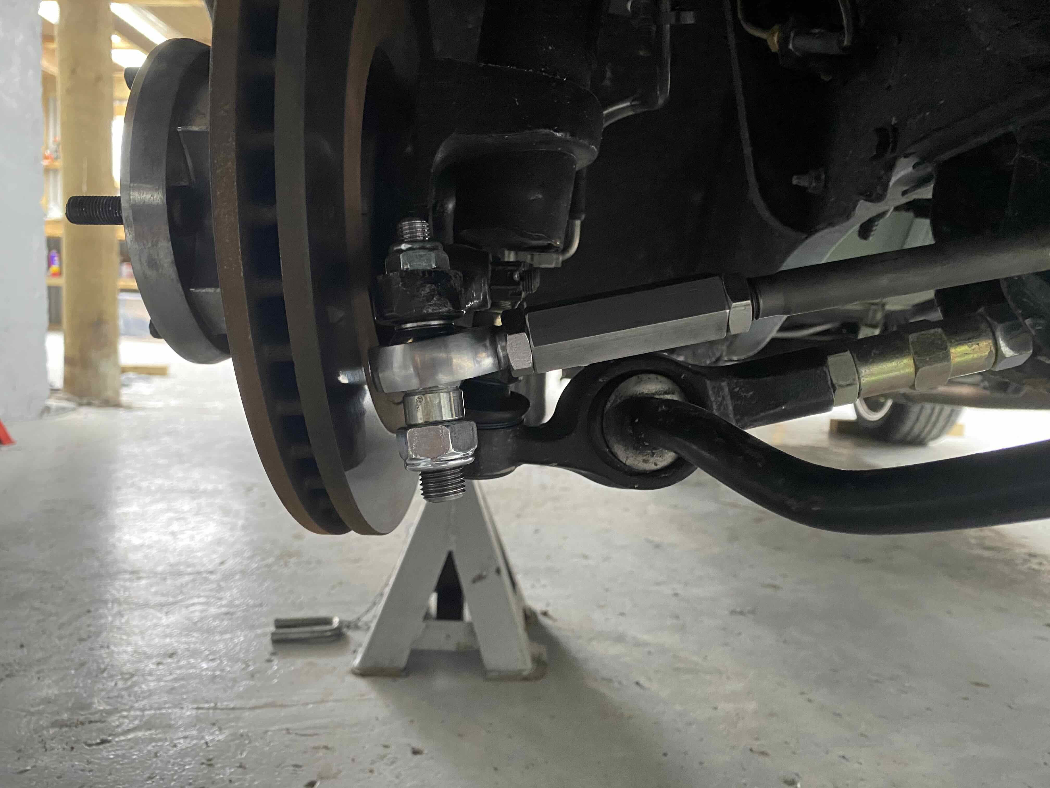
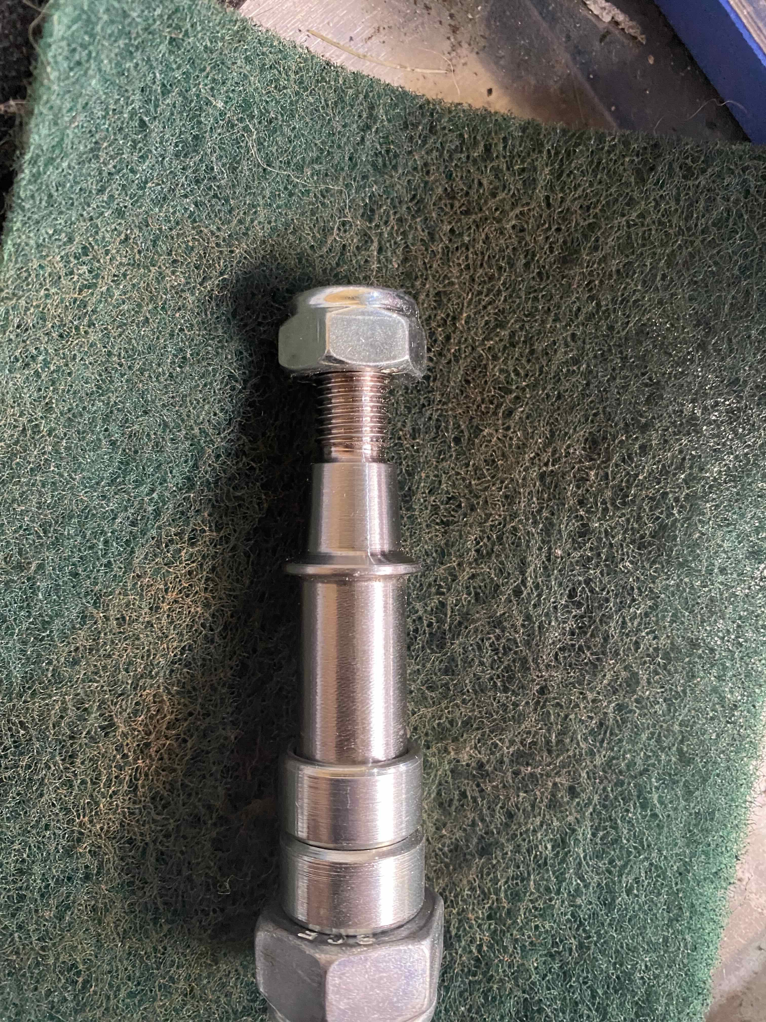
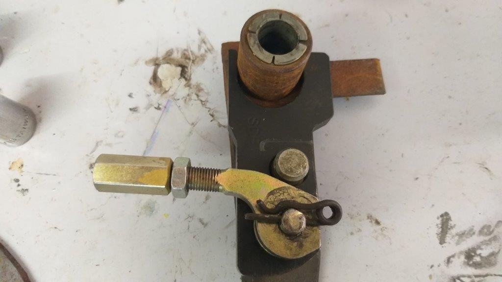
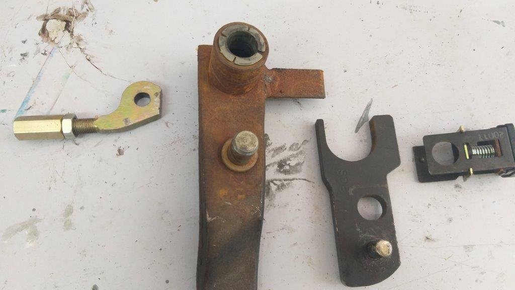
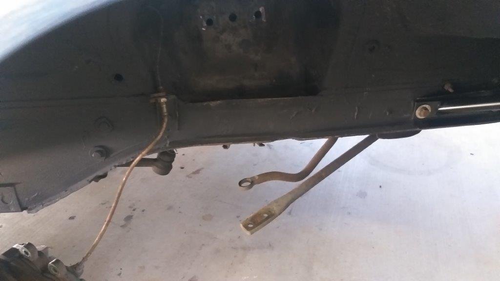
Rod end conversion bits all sorted now and fitted. Booked in for final alignment and bump steer check on the 19th and then will be on its way south for cert in Levin. Took it for a pre-cert wof type check at Douglas automotive week who gave her a really good going over and there don’t seem to be any obvious face palm issues that I’ve made/missed- bump stops required for rear, and heat shields for my surge tank and front brake pipe. I was having trouble with the handbrake working, previous master for the rear was pushing too much fluid so the shoes were adjusted to get a passable pedal feel but meant the handbrake wasn’t really working. Tried a smaller master for the rear And seems to have sorted the hand brake and given better pedal feel. Not too much left to do now, need to sort bolting the spacers to the Simmons wheels, bump stops should be too far away and matching tires for my other set of wheels. Hoping have it all legal by labour weekend for a bit of a road trip.
1 point
-
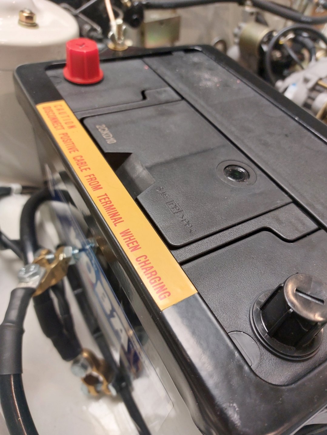
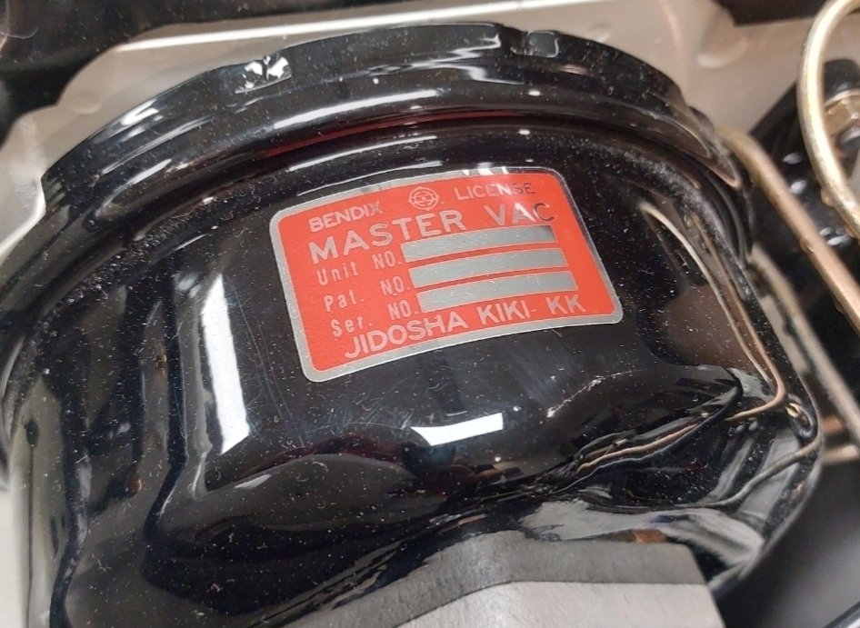
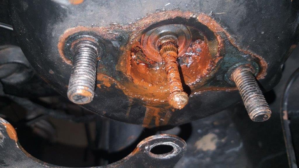
The newly discovered bent actuator rod on the old brake booster has been playing on my mind over the last day or two. Although I knew from day one of owning the car that the power assist wasn't working, apart from the pedal requiring more pressure I hadn't noticed anything untoward with the actual pedal movement or travel. In my mind there must be a reason for the mis alignment between the pedal pivot point and the actuator rod that caused this bend and surely whoever was doing the conversion should have picked this up during the installation. And if they didn't notice it whilst bolting everything together you would think that they would have smelt a rat when they tested the pedal movement and felt something binding up. The force needed to bend that rod surely couldn't have felt normal. So whilst I had the old booster out I decided to investigate further. Spent a few minutes fumbling about in the dark under the dashboard and managed to extricate the brake pedal. With the pedal on the bench in the light of day things took an interesting turn. Hello .... this doesn't look standard:
1 point
-
So back in December when I bought the Mustang the brakes worked okayish but needed plenty of leg power and I suspected that the power assist wasn't working. I swapped a few emails with @sr2 (AKA The Brake Wizzard) around Christmas time and with his help we diagnosed a faulty brake booster. I ordered a decently priced replacement that came complete with a new master cylinder. Both have been languishing in their packaging for a good while now, but today was the day. Started off by checking out the existing setup a little more closely. First thing I noticed is a brake bias adjuster mounted under the booster. Hullo .... that doesn't look factory. There is also a set of non factory looking firewall brackets that the booster bolts up to. So I'm picking that this car was originally delivered without power assist or if it was someone else has been here before. Okay, so after removing a few nuts and having to sacrifice one of the solid brake lines due to a previously rounded flare nut, I was able to seperate the m/c from the booster. Yikes, that looks a bit nasty:
1 point
-
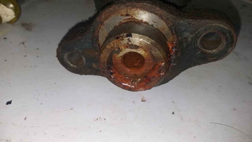
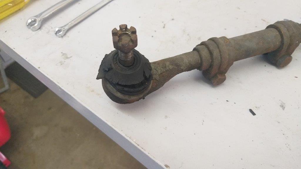
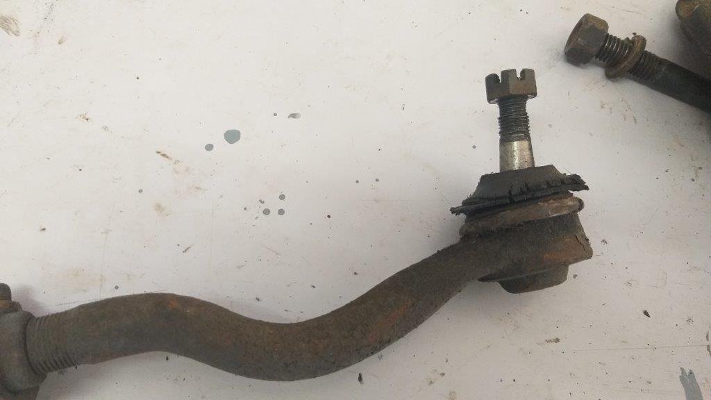
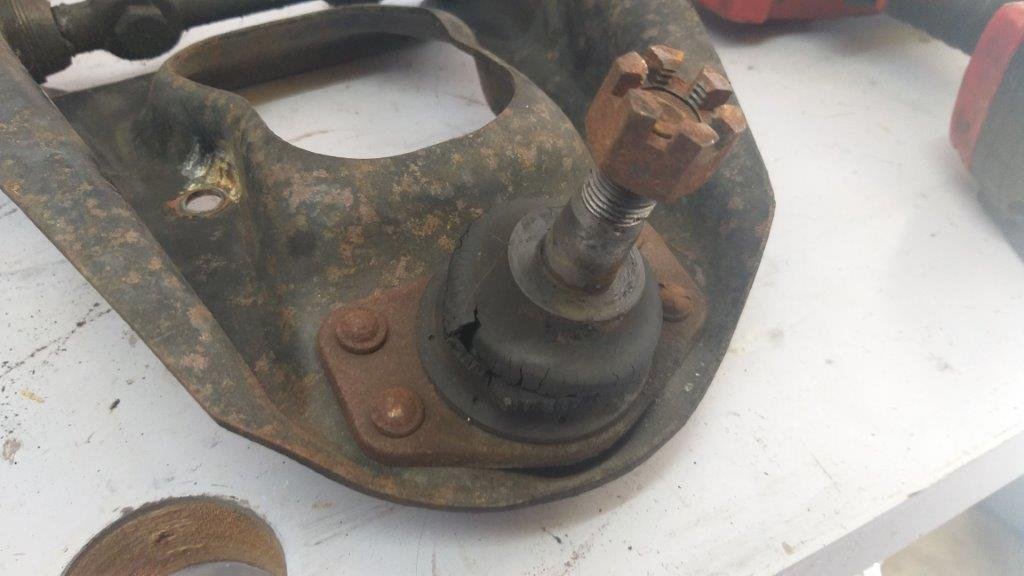
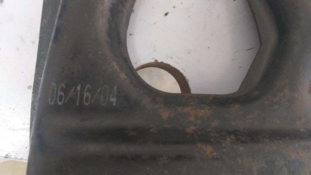
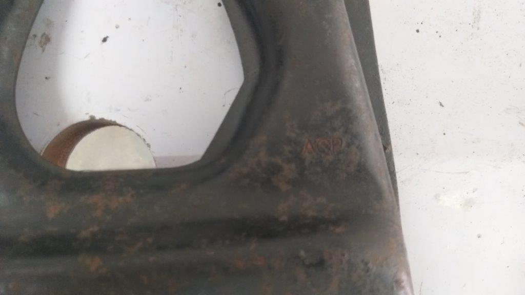
Got the driver's side suspension all back together yesterday and started taking the passenger side apart this morning. Lots of shagged dust boots and some notchy feeling ball joints and tierod ends. A bit more of the Mustang's history was revealed during the process. The upper control arm on this side is a repro unit manufactured by ACP. Date stamp says 2006.
1 point
-
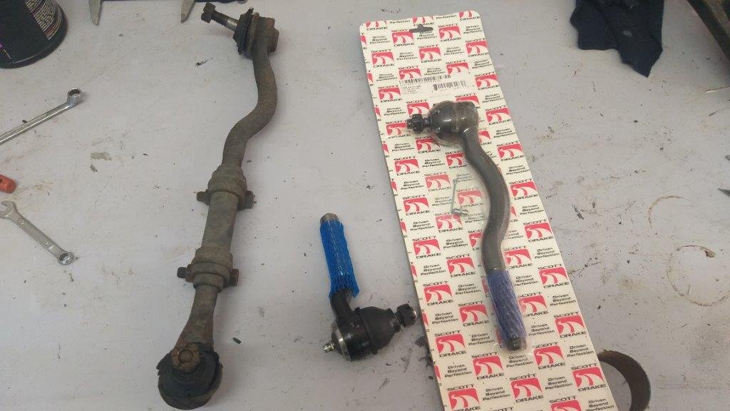
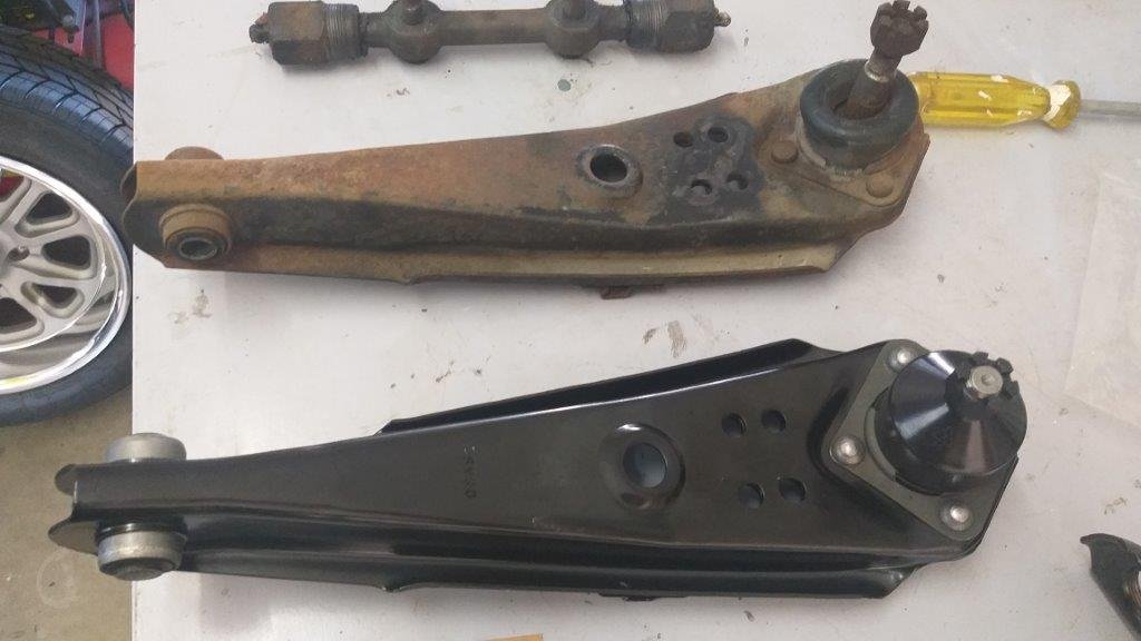
Next up are the new lower control arms. One of these newbies photo'ed along side his old mate:
1 point
-
Late yesterday arvo my final batch of front suspension parts arrived, so this morning I excitedly unpacked the box to inspect the goodies. First up were the high performance coil spring perches. As you can see in this photo the modified units are fitted with a grease nipple and the usual factory rubber bushes are replaced with a greasable polymer. My original units are completely siezed up, but the new unit rotates smoothly with a little finger pressure. Winner. These units should cure the lateral pressure that my front shocks were experiencing during suspension travel.
1 point
-
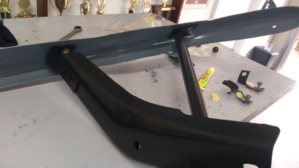
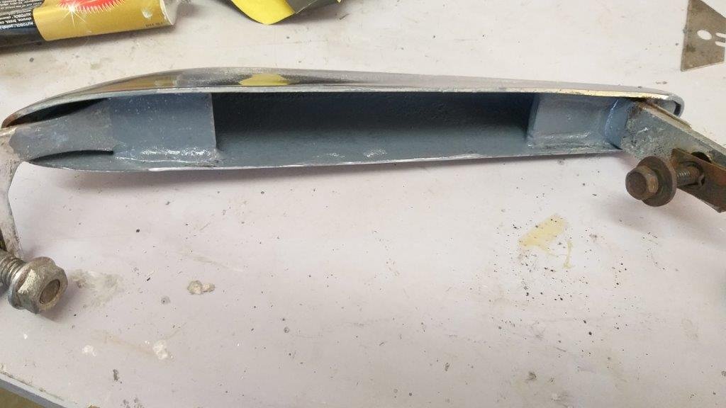
Late last week whilst patiently waiting for the rest of my suspension parts to arrive, I thought I'd finish off the last bit of exterior re-assembly being the front bumper and support brackets. But, before tackling that I wanted to have a go at sorting out the bonnet and front fender gaps which were pretty bad when I purchased the car. Whilst it all sounds pretty straight forward, it has been complicated by the fact that the car has previously been fitted with a reproduction right fender, under grill skirt and lower valance as part of the previous USA restoration and everyone knows that these non factory panels leave much to be desired in terms of final fit. Now a wise man would have sorted this out before final paint, but sadly I am not that man. Anywhoo I started off by loosening everything off then aligned the back of the bonnet with the windsheild scuttle panel. Got that as best as I could and then worked along the bonnet to fender lines on each side. After a bit of fiddling about I got those gaps pretty good then refitted the bonnet catch. Nope .... nowhere near going to work. Ended up getting physical with the bonnet pin and now for the first time the bonnet latches and unlatches smoothly. Flushed by my success I thought I was home and hosed until I tried bolting up the under grill skirt. Nope not even close. Tried the lower valance and again an instant fail. Okay .... Changed tack by loosening the fender mounting bolts, then loosely fitted all of the front panels with finger tight bolts. Then with a bit of pushing and pulling in all directions I finally managed to get everything to line up as best as I could. The front bumper and brackets are also reproduction units so they served up a few extra challenges, but after spending three full mornings on it I've declared a victory. The final fit is not 100% prefect, but it is way better than it was .... enough to quell my OCD, so I'll take the win. Sadly without its suspension in it's not a roller so I haven't been able to take any photos of the results which I will do as soon as it is back on its wheels. Now no one likes a pictureless update so here are a few photos of the inside of the reproduction front bumper and over riders which were badly rusted inside and are now sporting a protective coat of epoxy primer after a good de-scale. Thanks for reading.
1 point
-
9New direction, I was taking the fog lights off when I remembered I had a box of lights that might work. So now I have DRL's instead, dekatora running lamps. I have some spare if anyone is keen.1 point
-
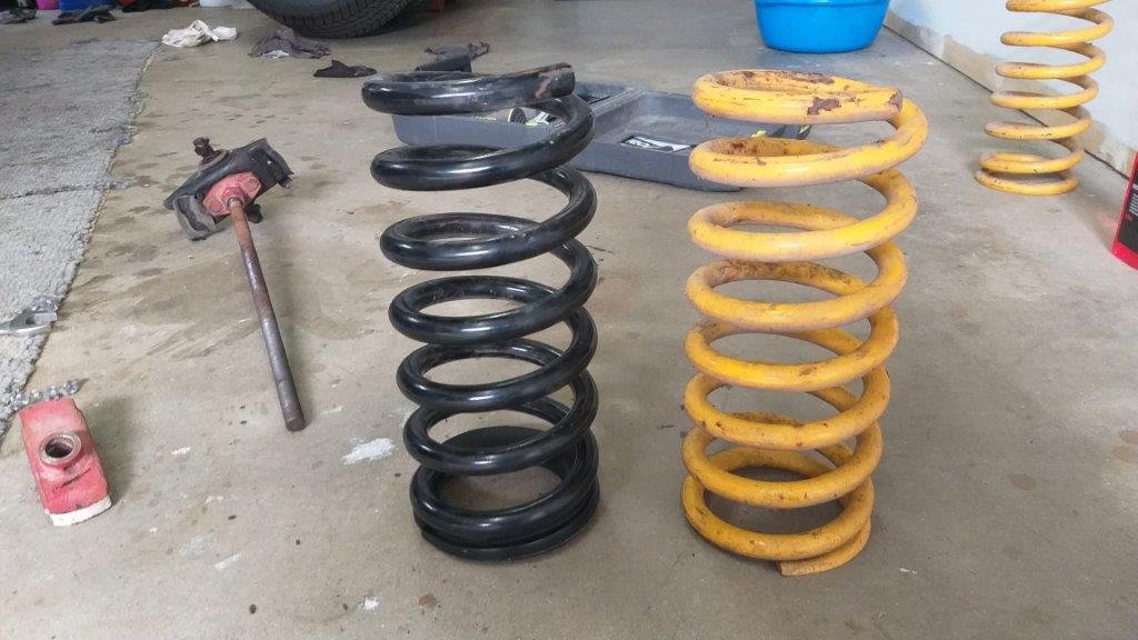
My plan was to tackle the brakes next, but I soon discovered that I needed to source a set of imperial sized flare nut spanners if I had any hope of seperating the brake pipes without things ending in tears. So with those on order, I moved on to the next item on the list being the refurbishing of the front suspension and steering components. First step was to do something about the front ride height. Back in 2014 the previous owner fitted a set of 1 inch lower front coils, but these just weren't cutting the mustard, especially after I dropped the back by a further 2 inches. My mate Grant had a set of KingSprings that he had pulled from a Falcon a few years back and he suggested that I give these a trail fit with the thought being that I could always give them a bit of a Makita haircut if they were still to high. Grant also lent me his Ford specific spring compressor tool which made the job an absolute breeze. So yesterday morning I did the old switcheroo and I'm pleasantly surprised with the results. The photo's tell the rest of the story.
1 point
-
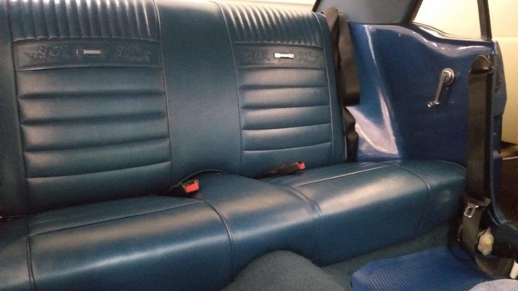
Got the parcel shelf, back seat. rear underlay and carpeting in. Looks like the seats were recovered as part of the major renovation that took place between 2010 and 2012. As a result they just needed a good clean underneath as they had a lot of tar like smears from the old sound deadening Once the seat was in I fitted the front and rear seat belts. I'm going to leave the front carpet, centre console and seats out for the moment as I need to replace my shagged brake booster and I figured it would make grovelling under the dash a lot easier. So it's on to the brakes next. Thanks for looking.
1 point
-
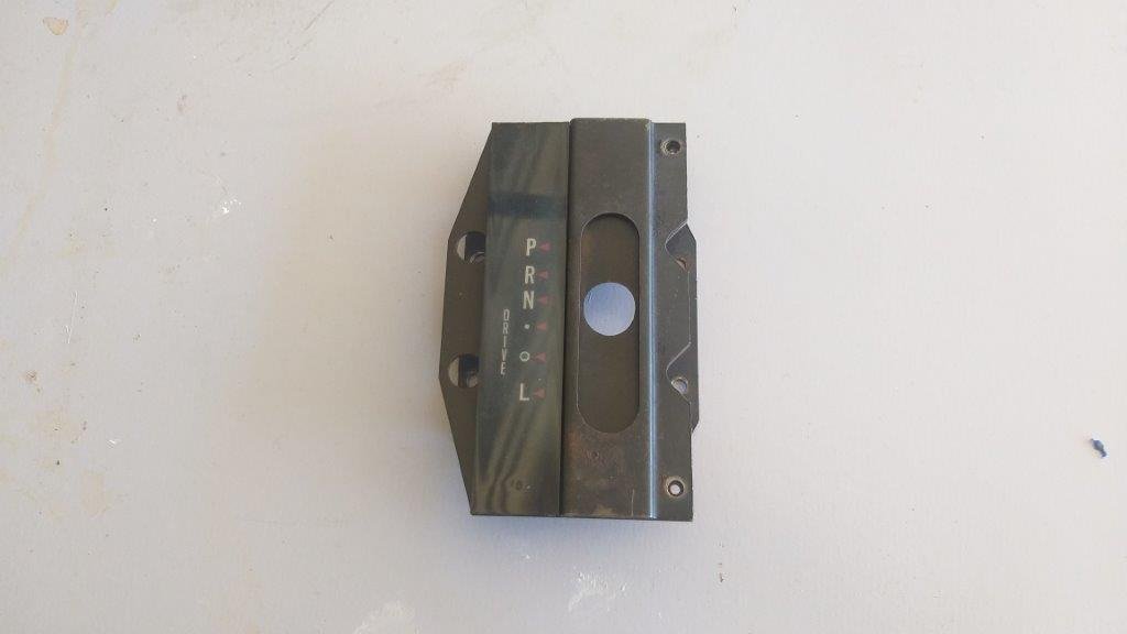
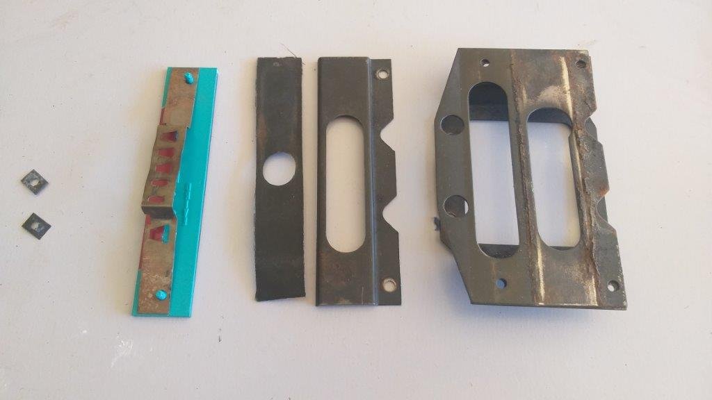
And here is the last interior bit that is in need of some loving. Pulled the shifter surround out and up close it looked pretty tatty. Covered in 50 year's worth of dirt, grime and surface rust. Stripped it down to it's components, gave the metal bits a good sand, primer and paint and then reassembled with a fresh face plate. Much better.
1 point
-
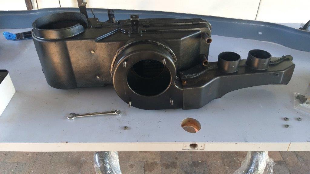
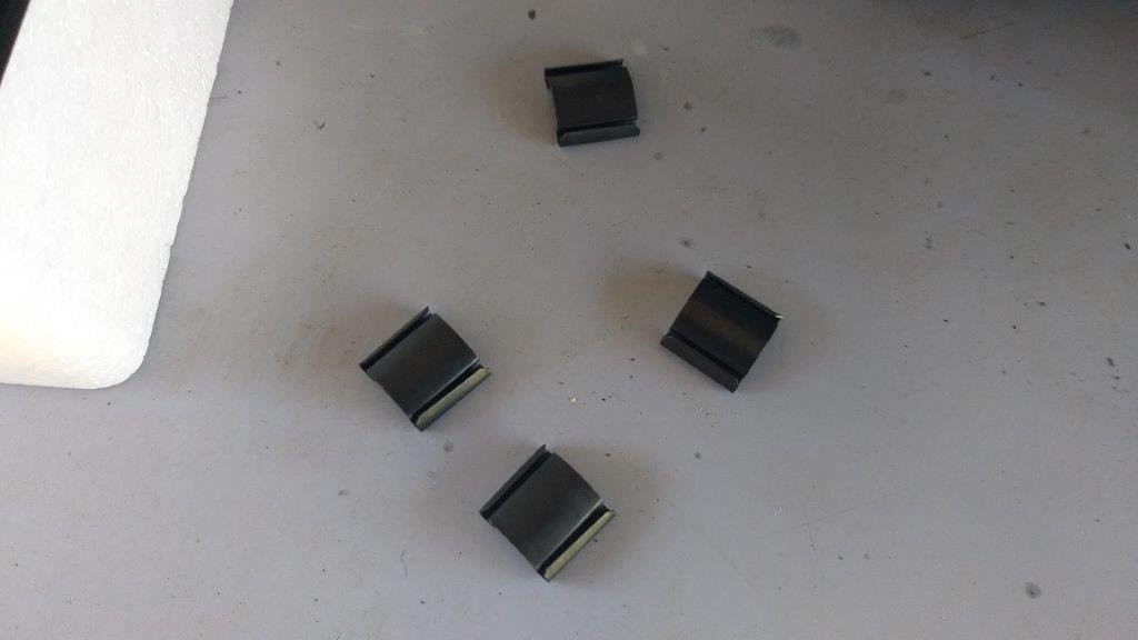
Today was another one of those "one step backward" situations. After refurbishing and reinstalling the heater box a few week's back I wasn't completely happy with the result. The blower motor sounded a bit like a coffee grinder and I figured if I left it as is it would irritate me no end. Figured if I was going to do anything about it now was the time while I still had some of the interior in pieces. Ended up ordering a replacement motor in my latest parts shipment. So, out came the heater box first thing this morning and I did the motor swap. When I originally refurbished the unit four of the eleven little clips that hold the casing halves together were missing, but I didn't have replacements at the time, so just had to make do with the available clips. Got some new clips at the same time so those went in too. Much happier now. The new motor is nice and smooth and I can now move into top gear on the reassembly of the rest of the interior.
1 point
-
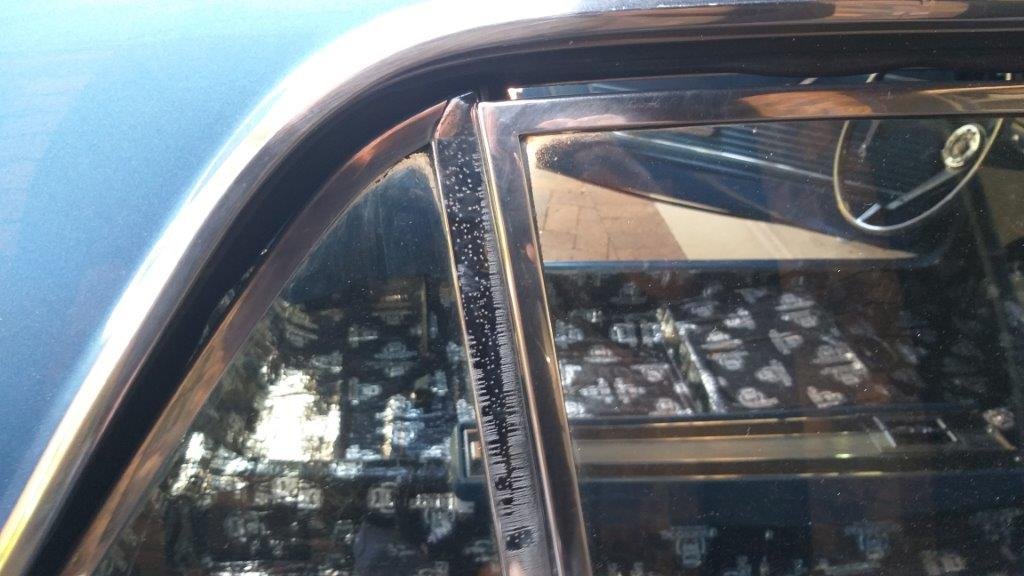
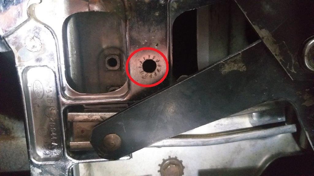
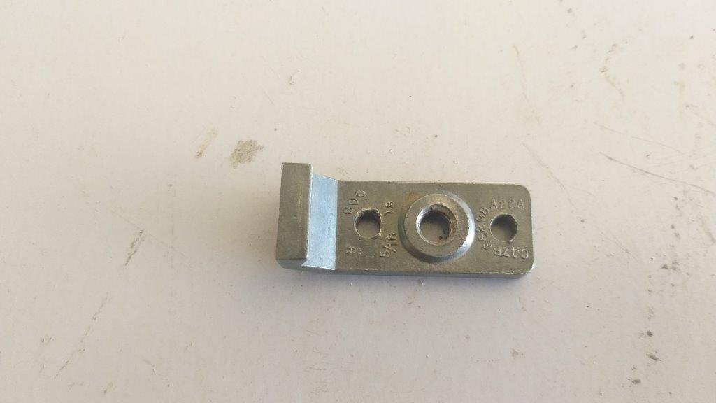
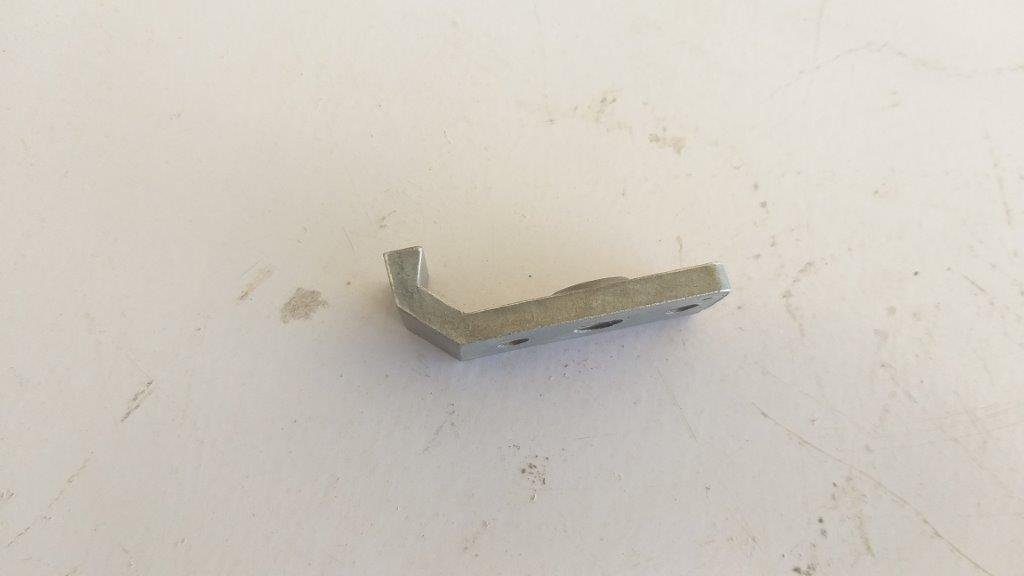
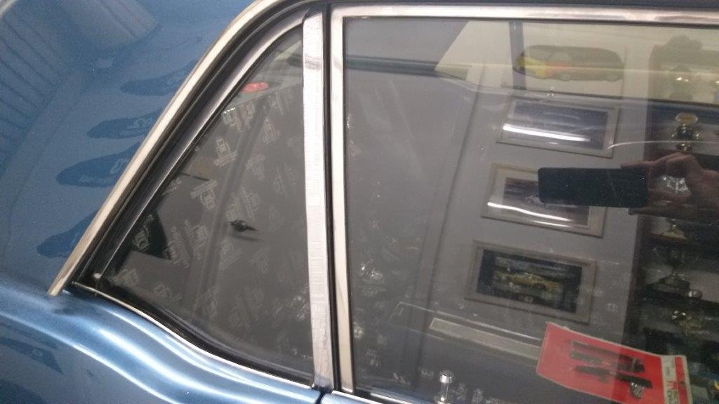
The second window issue being the intermittent misalignment of the passenger side rear quarter window was slightly more tricky to solve and only because I am not the sharpest tool in the shed. So my first step in trying to resolve the issue was to fiddle around with the window alignment, but try as I might I just couldn't get a consistent result. After faffing about for about an hour I decided to strip the whole glass and mechanism out. The first step of the tear down is to remove the window bumps stops. It was at this point that I realised that one of the two upper bump stops was missing.......... and that is when the penny dropped for me. The missing bump stop was allowing the window to tilt slightly forward towards the end of its upward motion ...... bloody bastard ! The missing soldier is circled in red in one of my photos below Now I'm very fastidious when it comes to stripping things down. Everything gets bagged and labelled and all of the parts associated with a particular item are stored away together in their own plastic bin. Since neither the bumpstop nor its mounting bolt were left over in the container I'm almost positive that this bump stop was missing before I stripped the window down. I searched around in my storage location under the Thames van in the hope that it might have fallen out of the storage bin, but no such luck. So now to find a replacement. Easier said than done. You can get repro replacements ..... US $75 for a pair ...... gulp. Bugger that .... I only need one. Then by a stroke of luck I spotted an eBay listing for a single pre-owned one here in Aussie. It was listed at OZ $31 including postage which is still rather spendy for what it is, but I figured what the heck, take the coward's way out rather than spending hours fabricating a replacement. Anywhoo, it arrived earlier today so I slapped it in and hey presto .... the window now aligns perfectly every time. I am now a happy bunny. Thanks for looking.
1 point
-
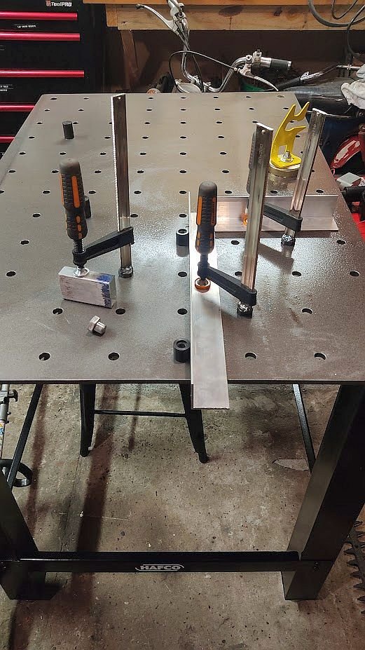
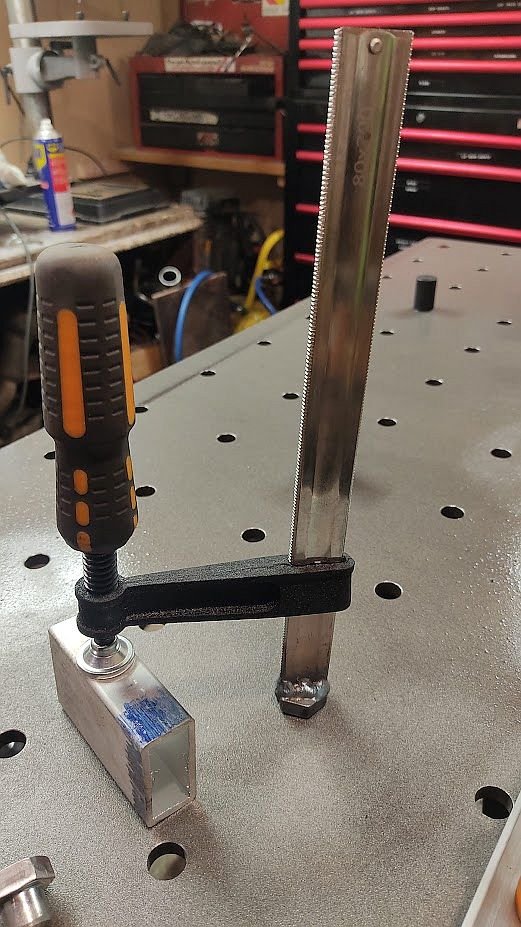
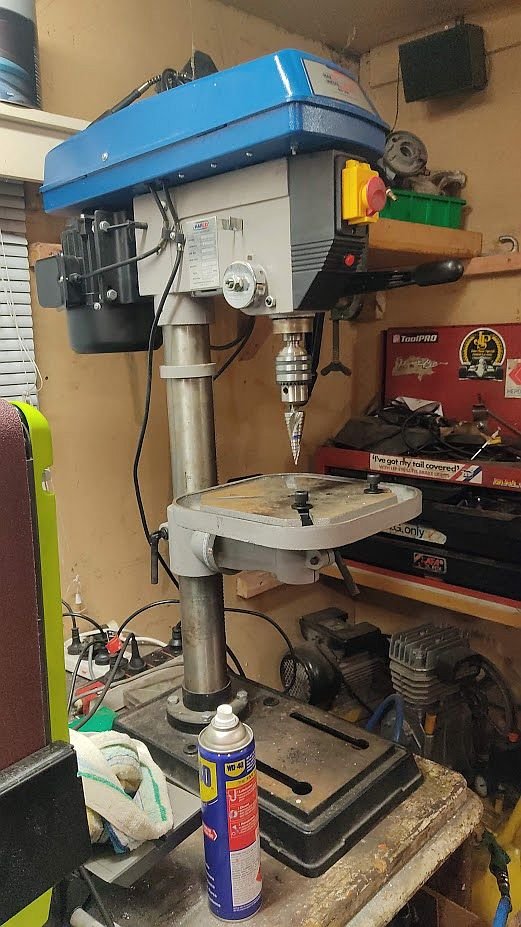
Somewhat related to welder buying... For the last few years my welding "table" was a small piece of 12mm plate with a section of angle zapped on the back by a seagull with metallic diarrhea, the angle got clamped in my vice to give a surface as well as tie up my vice to prevent it being used for anything else etc. Well that's changed! Managed to sell my old DC TIG and my last .22lr for more or less the exact amount needed for the table, got to Machinery house on Friday and it turns out they have a sale starting today so they gave us the sale price and then a further $50 off with their "mates club" deal. It's no certiflat but fuck I am over the moon with it!! Modded some M16 bolts in the lathe, welded on Bunnings F clamps *Don't look too close, I'm still figuring out MIG* Oh and much less related, ol' @Geophy had a mate selling a drill press last month and it's found it's way to my shed too.
1 point
-
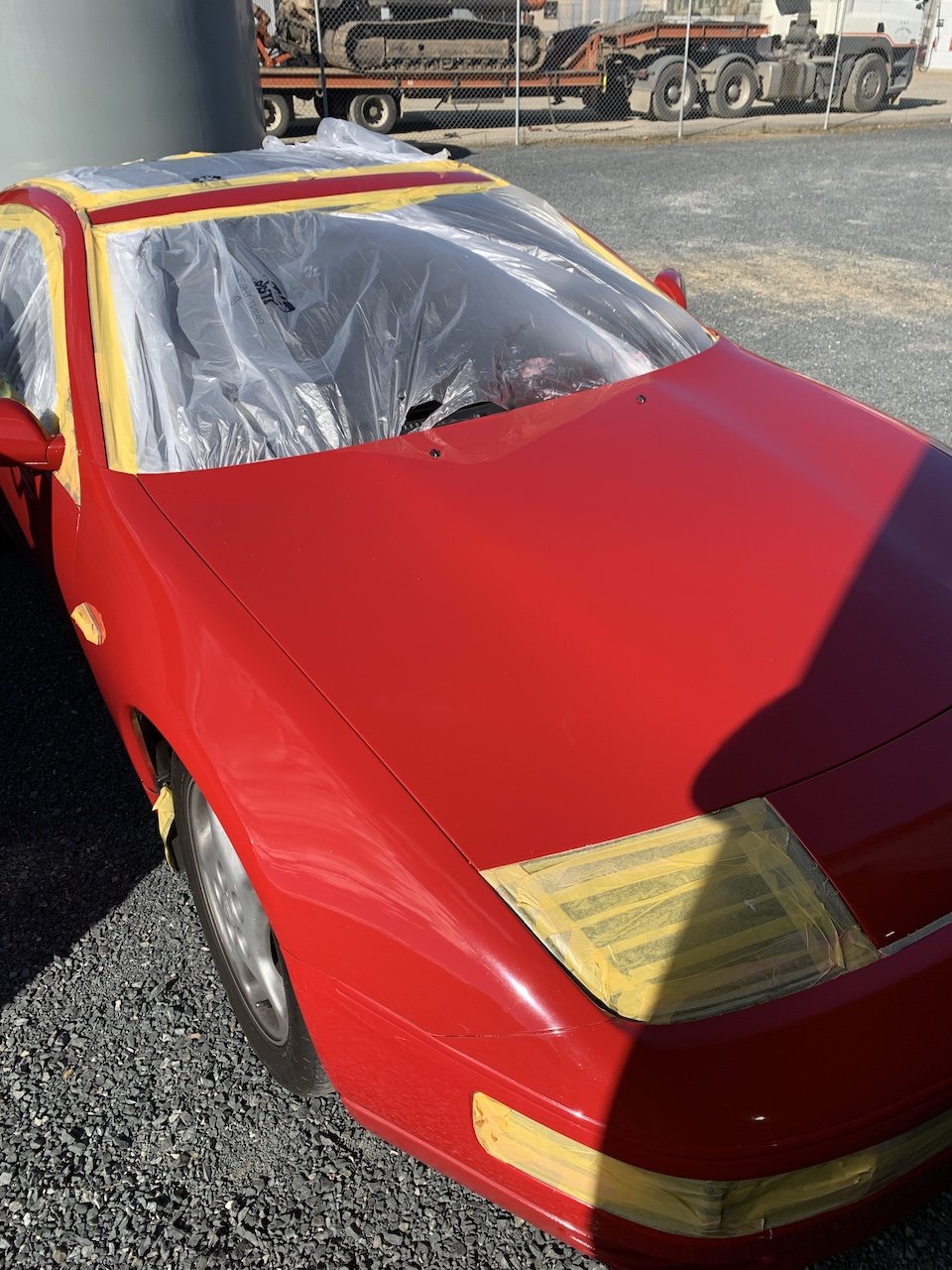
Masked her up and gave her a cut and polish. The drivers door, A pillar, rear fender and bumper are still original paint so were a bit dull compared to the newer paint. It came up really good, still differences in the colour but only if you go looking for it. Dropped off to a mate who is doing the rocker cover gaskets, replacing some pipes, upgrading the headlight bulbs anda few other little bits and pieces. I've ordered a new sticker for above the taillights too. Should have an update on wheel availability soon too.
1 point
-
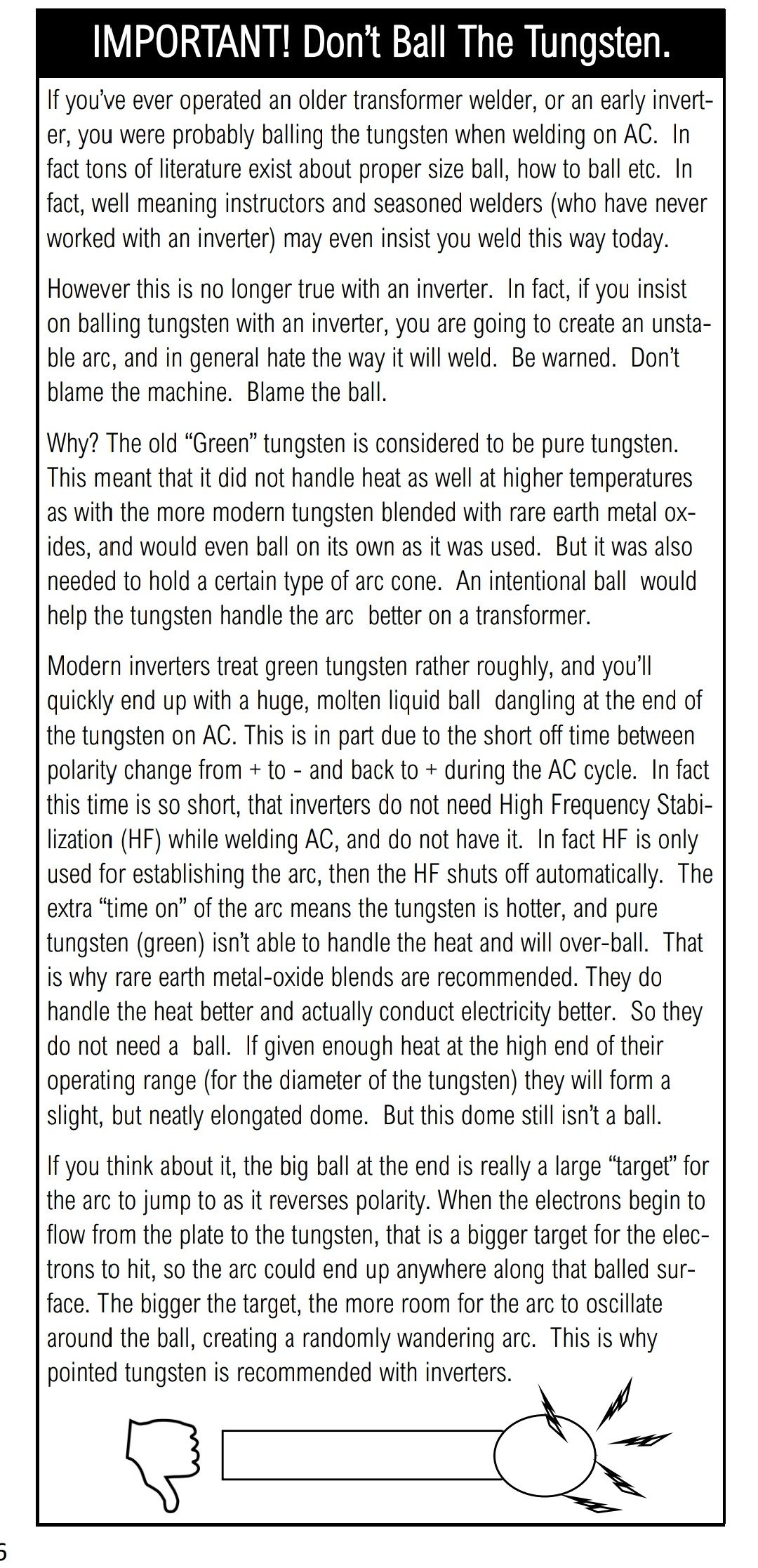
Downloaded an Everlast instruction manual, so much more detail than BOC give. 0 is 50/50 balance, so either -30 or 30 is 70% (I'm still reading it lol) I've been aiming for balled tungsten the whole time lol Edit: Between the Everlast instructions and the video @Transom posted I think I've got it figured it, -30 is 70% negative. it was about 30 where the tungsten was balling and splattering away so yeah that would have been 30% negative.
1 point
-
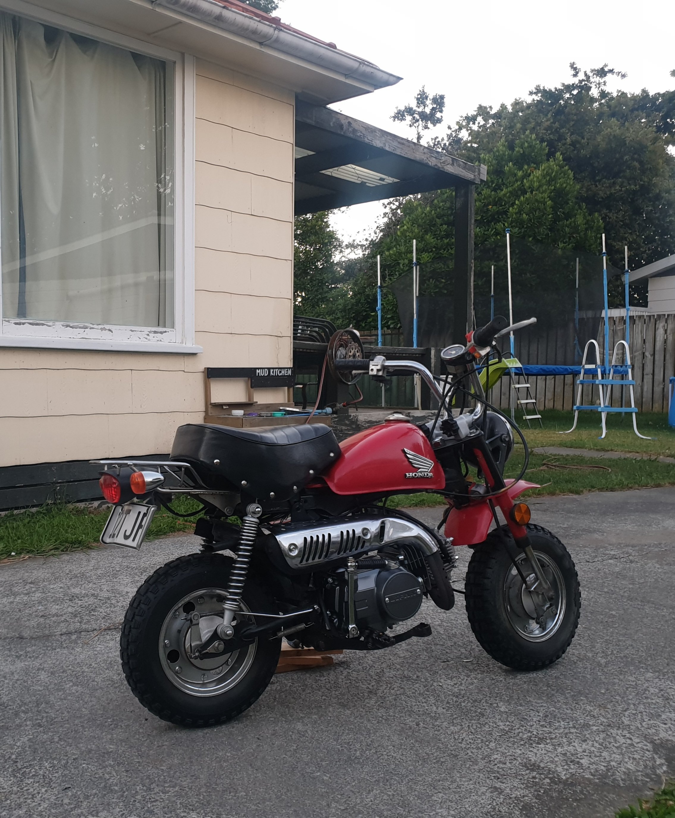
Mostly finished took for a ride goes well verrry pepy still small finishing stuff but 1st ride complete
1 point


.thumb.png.b2aee08688778d18bdc7b3e3c1852d9c.png)


This leaderboard is set to Auckland/GMT+12:00