
Leaderboard


Popular Content
Showing content with the highest reputation on 01/22/24 in all areas
-
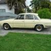
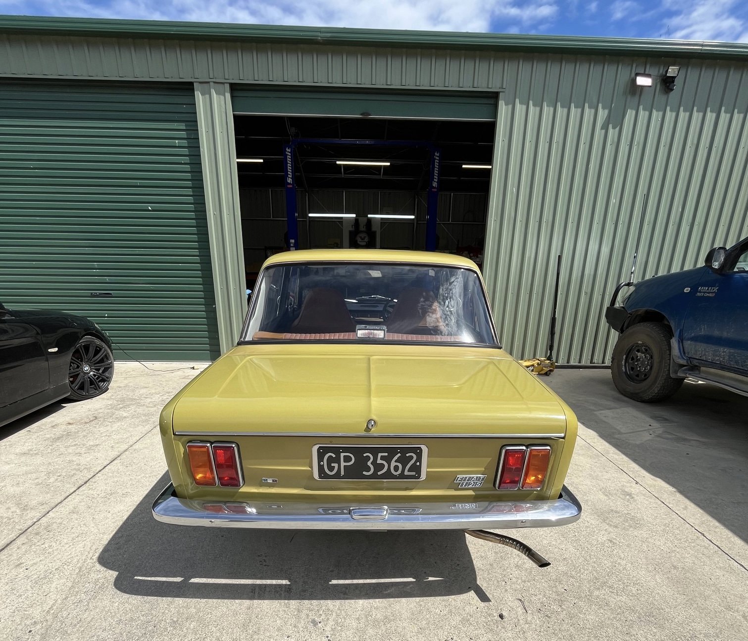
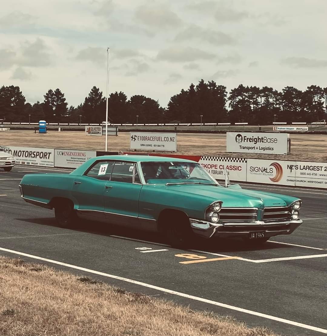
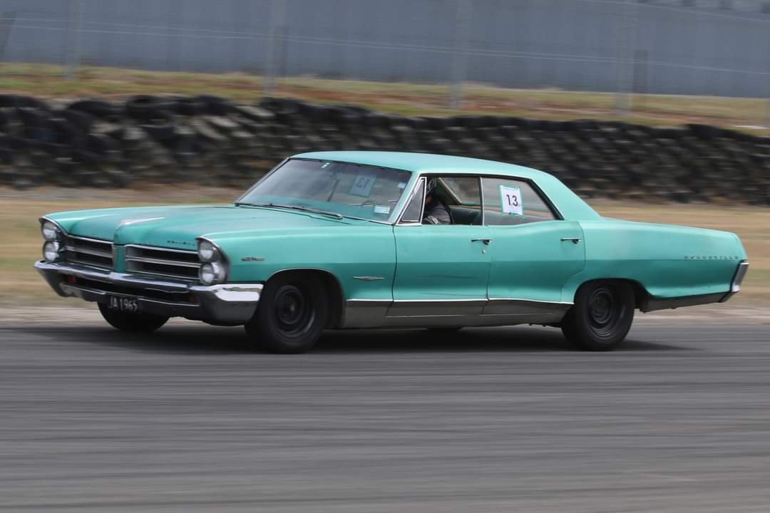
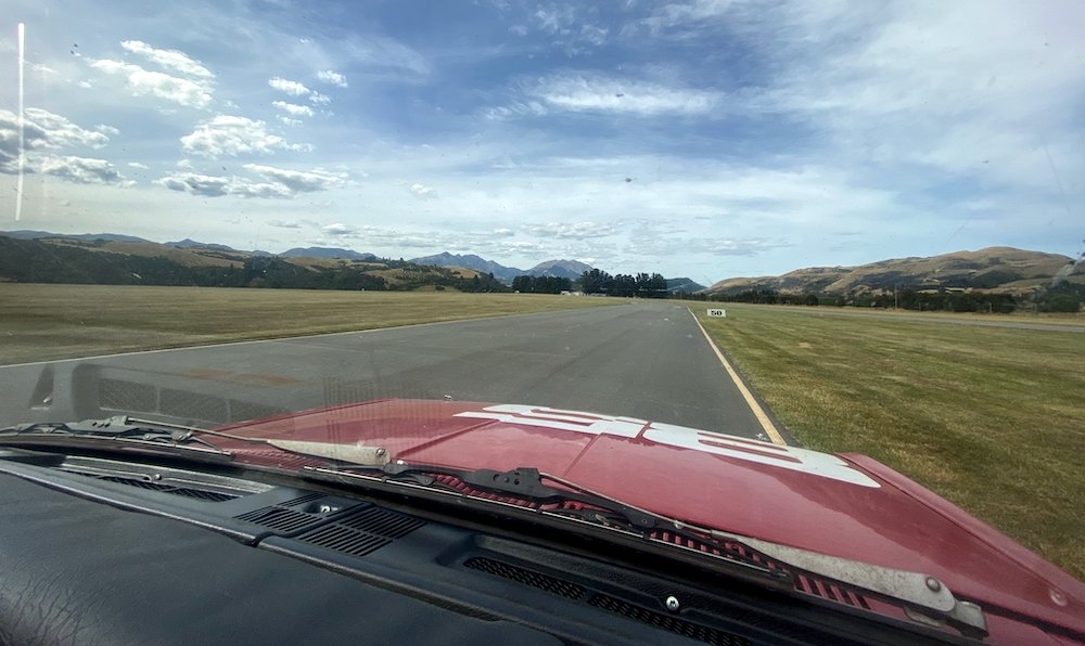
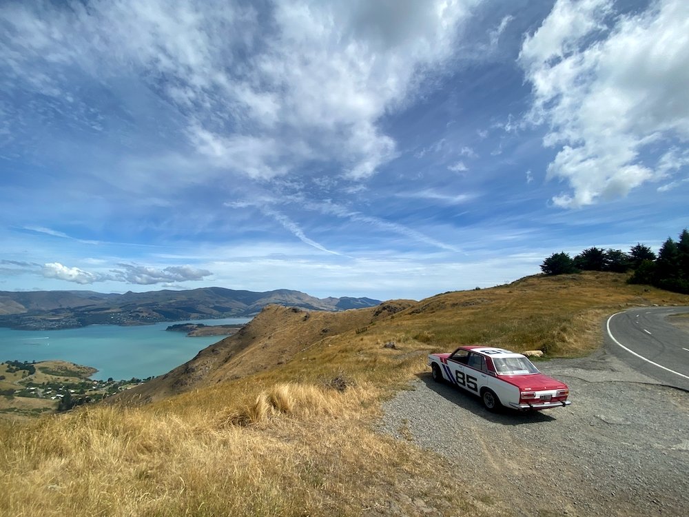
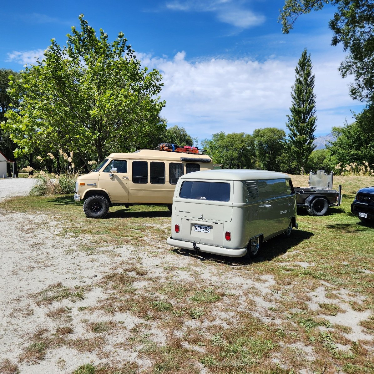
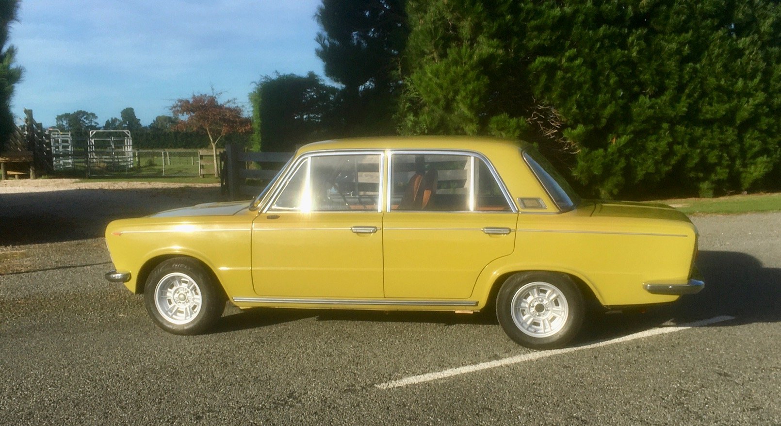
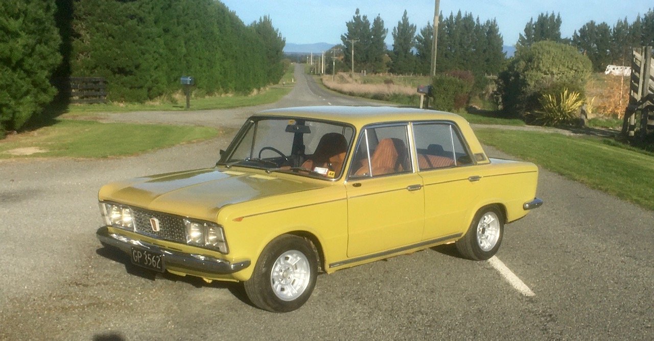
This thread needs a decent pic of the car right? Really want to go get some sunrise/sunset pics, but that will need to wait til daylight savings pulls the sun back to more gentlemanly times, for now, a not so potato pic
 17 points
 -
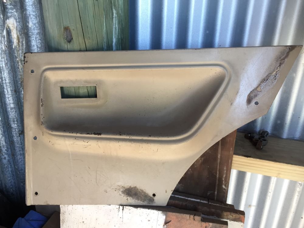
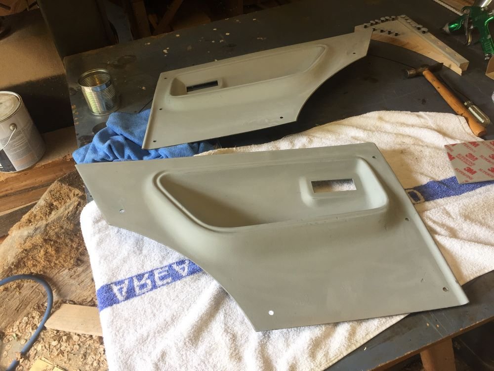
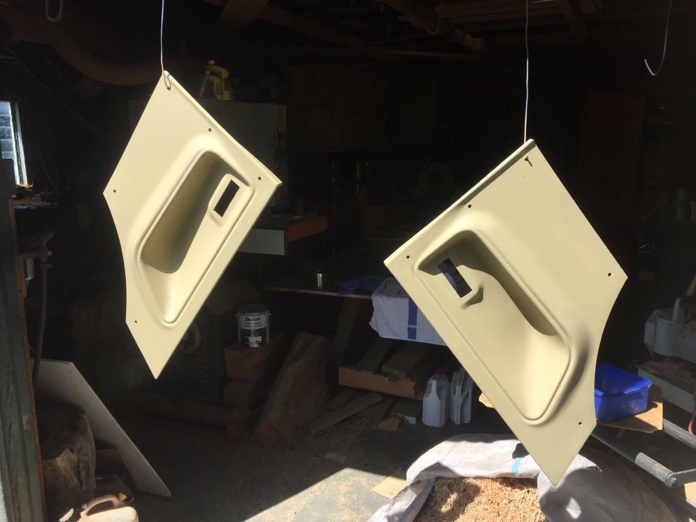
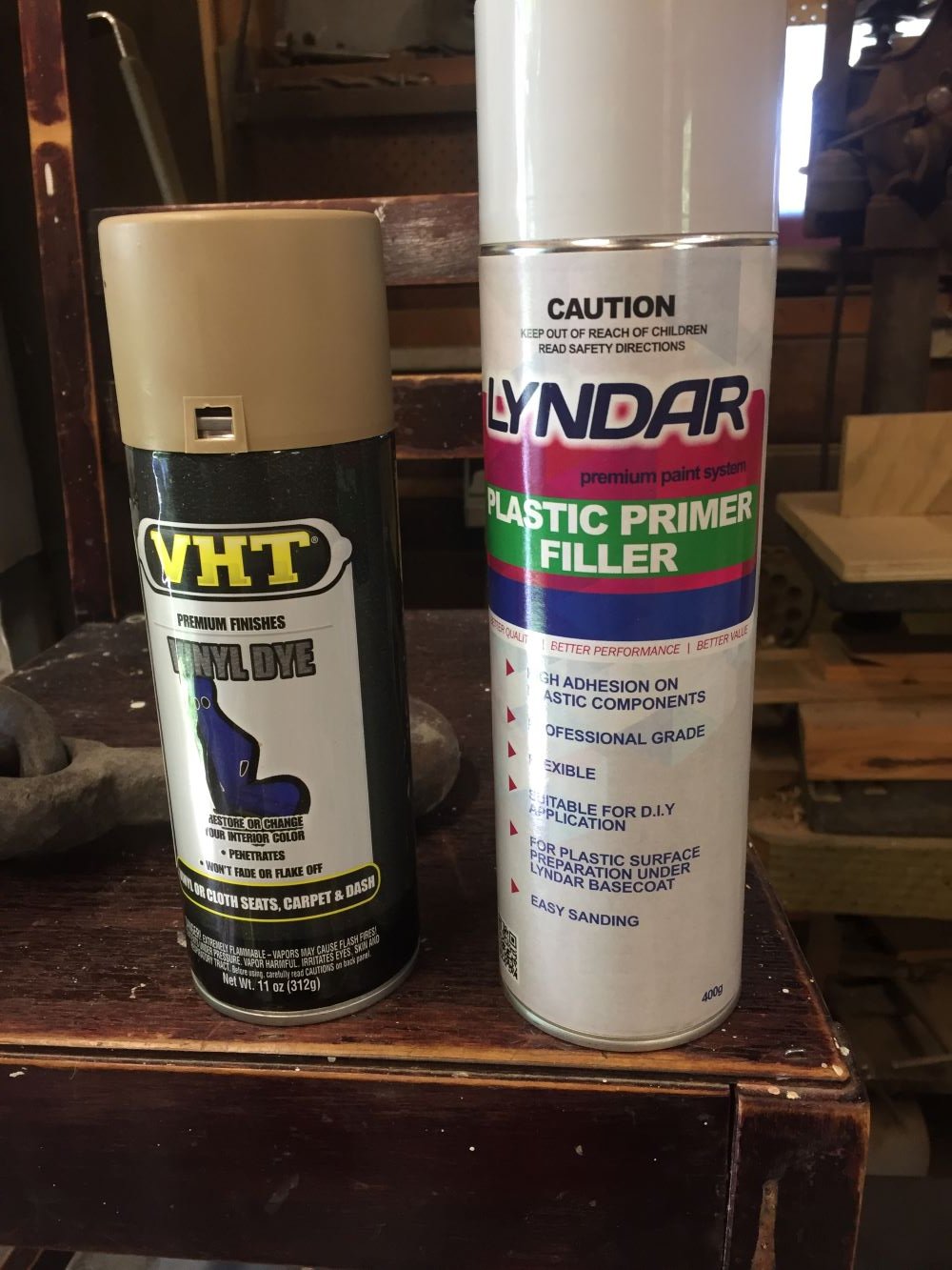
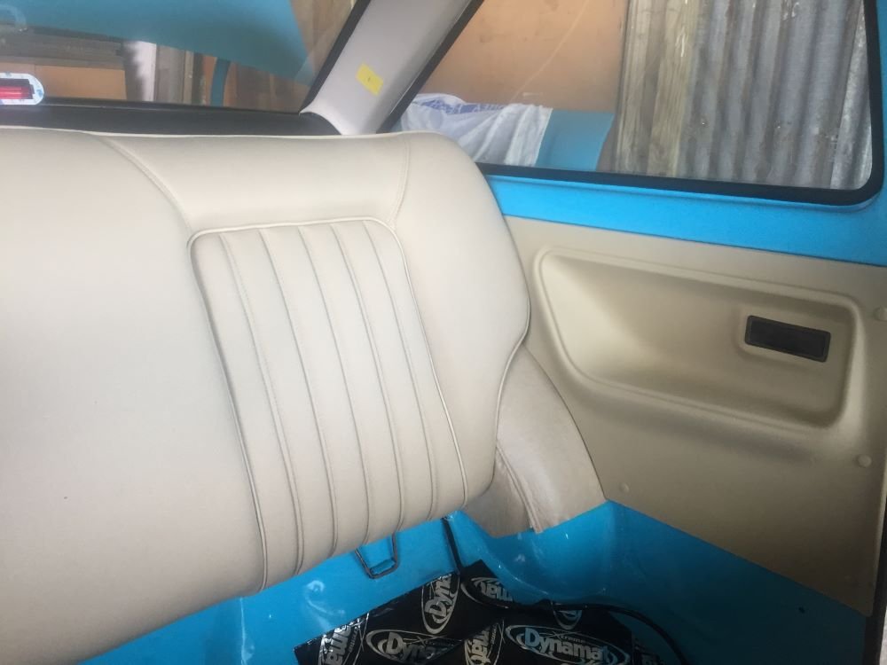
Made a start on the interior of car by refurbishing back seat trim. Removed ash tray and lightly sanded panel. Next sprayed with plastic primer filler then lightly sanded again. Finished with vinyl dye which came up really well. Did the same process for clips. Fitted ash trays after spending some time getting them to work properly. Now to install parcel tray and boot divider panel and also vinyl wheel arch trim. Fitted new c-pillar trim after marking seat belt mounting points incase I put seat belts in the rear. Finally put in rear seat back. Looking smart
10 points
-
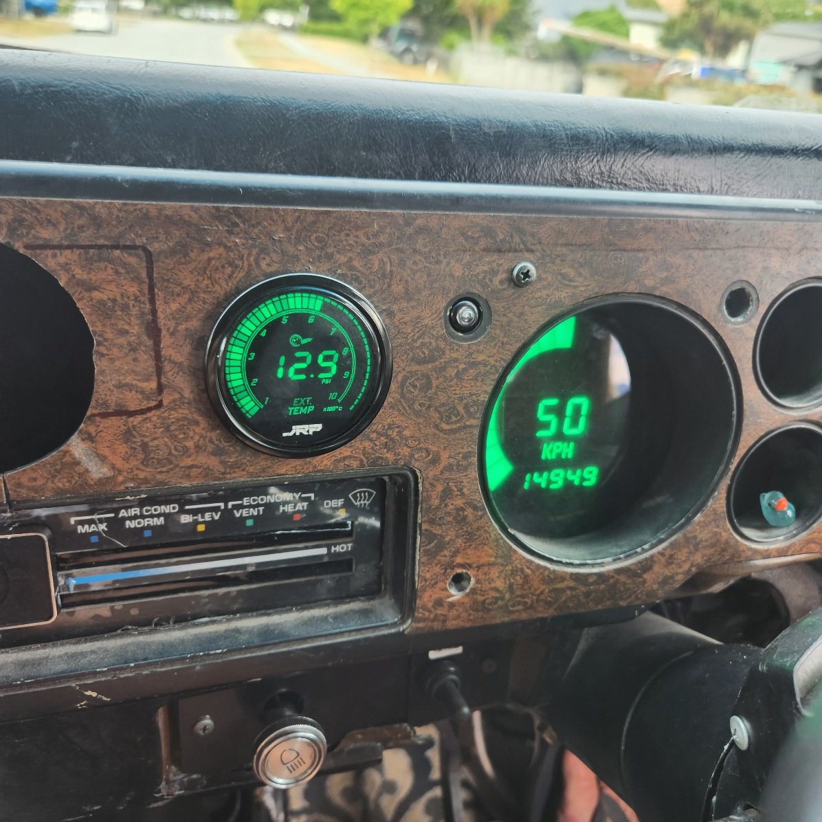
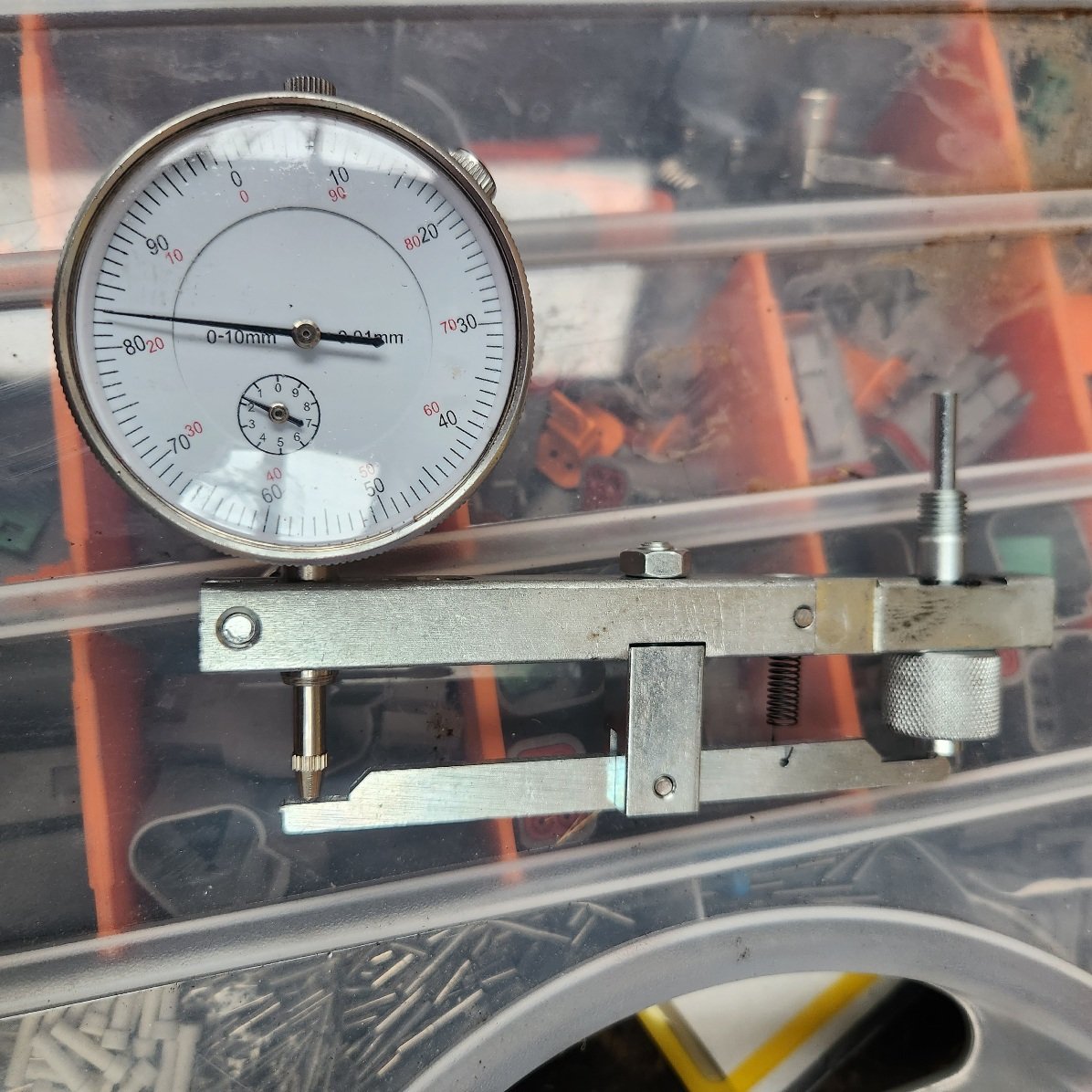
Welp, I got the pump and injectors back, old mate said 3 were leaking and nasty, the pump is a work of art, not sure what got reused. Anyway slapped that all in and timed it with a timing tool i got off eBay, man what a rig, much better than trying to hold a dial indicator while turning the crank The difference in performance is major with the new pump etc, it pulls straight away and got up to 100k no sweat, egts were getting up there so pulled the boost back from 17 to 14 or so and will try that. I also put an exhaust temp gauge in, I got a combo one that matches the dash. I also found a NOS dash for it to replace the shit one in there Also had a win with the slow start, after a ton of braining I ended up putting the meter on the fuel cut solenoid power line and sure enough, voltage dumped when it was cranking, like to 0 dumped. So traced the harness back and pulled fuse block out etc found a pin pushed back on the plug into the column that goes up to the key, happy days. It lights on the first bump of the key now like it should.
9 points
-
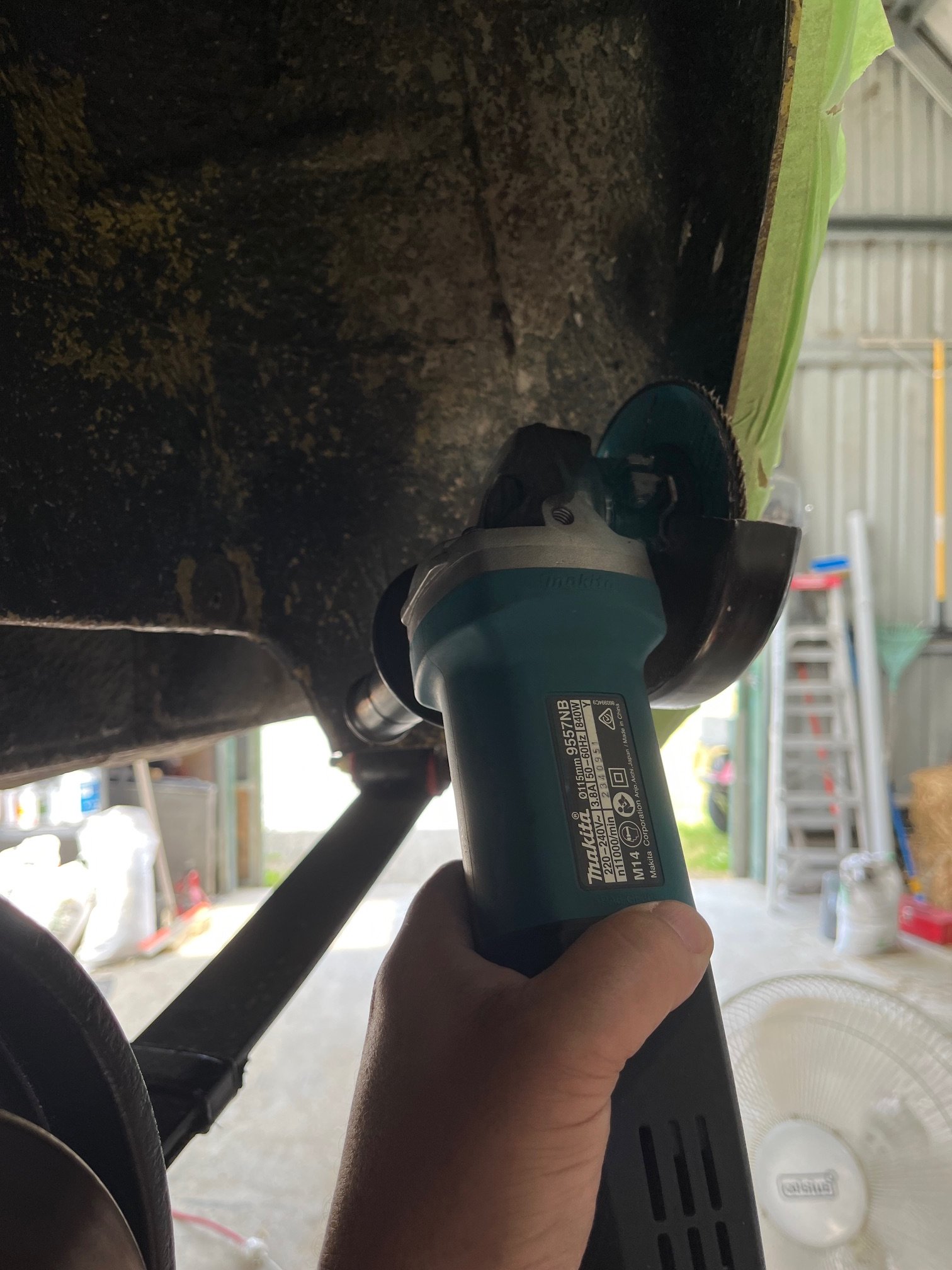
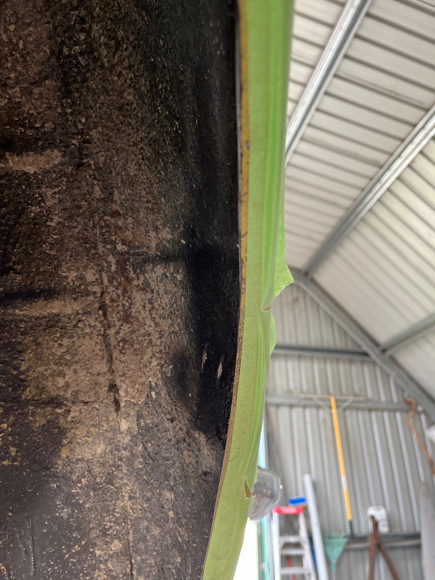
There is still an issue of tyre rub when loaded so I put some ballast in the back (wife and kids) and tried to find the pain points. It looks like it’s rubbing on part of the arch lip, so more trimming required. Previously I had thought it was only in the inner guard where it was touching as I had put a guide coat in there and found a high spot that the tyre polished off. I made the high spot lower with a hammer and it doesn’t appear to touch there anymore. I marked out the lip with tape and then used a flap disc which made very short work of trimming. Anyone with half a brain would say “why not just use the correct wheels and tyres” well, I have a WHOLE brain buddy, and the correct course of action is obviously to cut up your car until the phat wheel/tyre combo fits! *UPDATE on alternator light shenanigans. Since the Fiat uses a relay to power the bulb, and it’s a normally open jobby, wouldn’t a normally closed relay correct my back to front light situation? I dropped by the local auto sparky with my hypothesis and he agreed. So 5 minutes later the relay was swapped out and voila, it works proper.
7 points
-
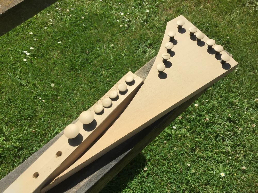
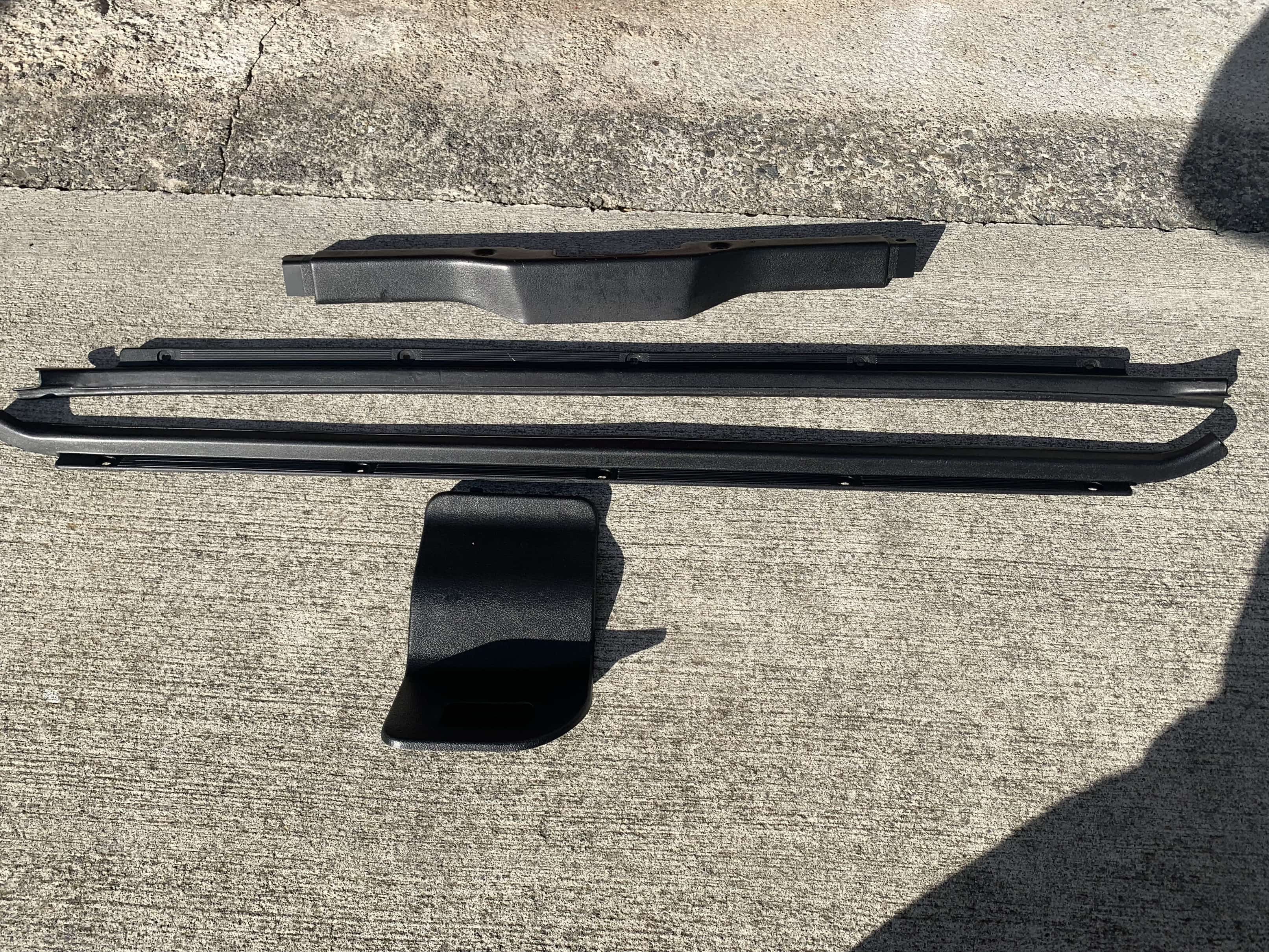
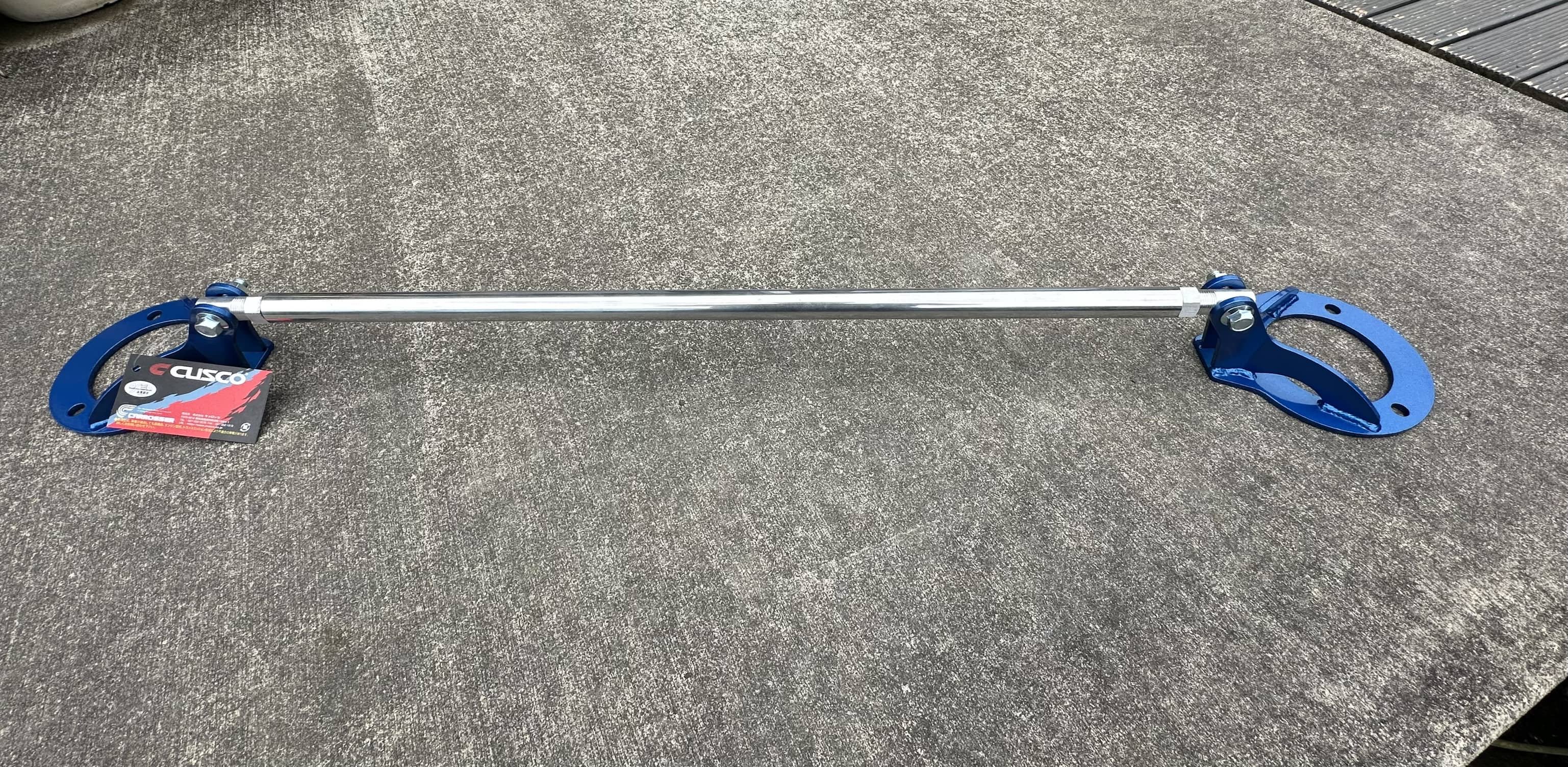
Work slowly continues on the starlet, lots of little jobs being done when time allows. Bumper brackets are currently being sandblasted & the warm weather we are experiencing in Wellington certainly helps with getting the paint to dry. I’ll be going with a black interior so I started to paint some of the trim. First a wash in warm soapy water then a spray with plastic and vinyl paint Have also spent way too long on rhdjapan.com lately and my first lot of parts arrived. Some ARP bolts for the engine and a Cusco strut brace. The colour of the mount is fairly close to the colour I’ll be painting the car so that’s a little win.
7 points
-
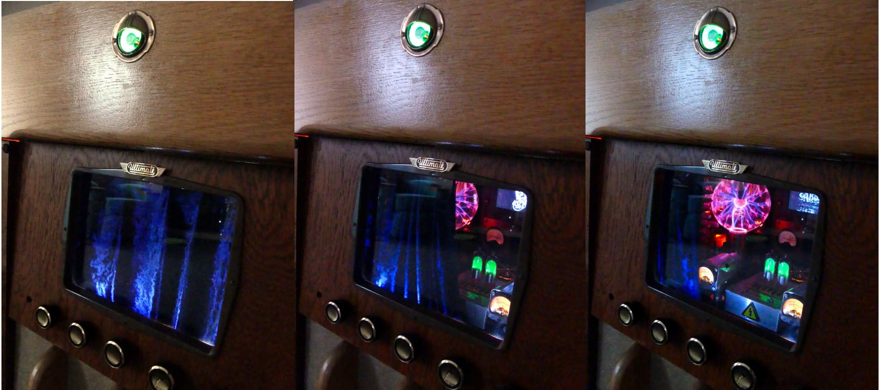
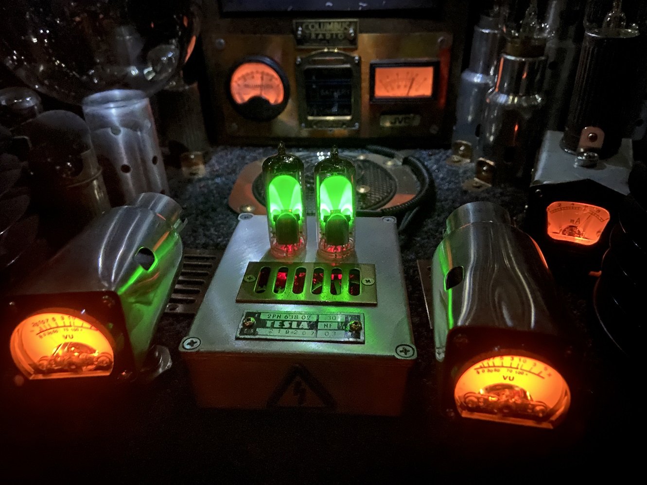
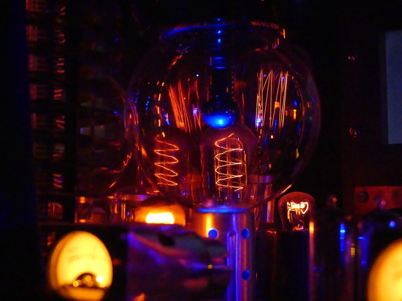
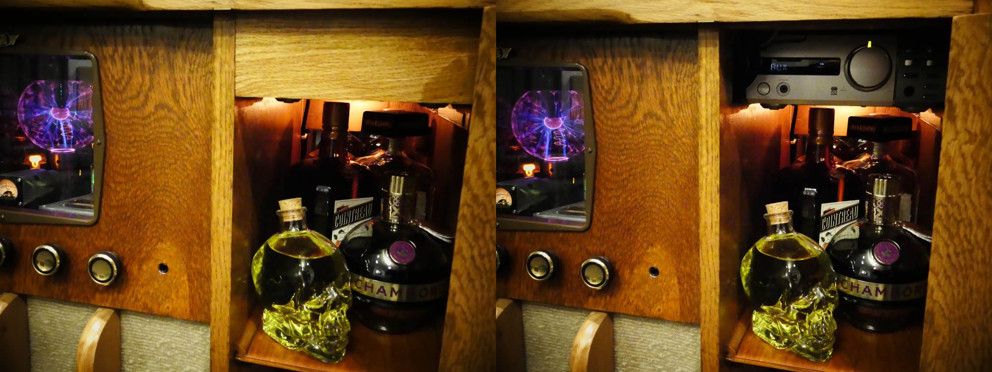
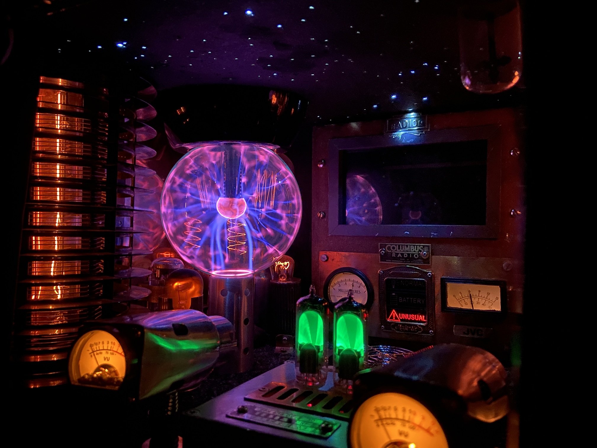
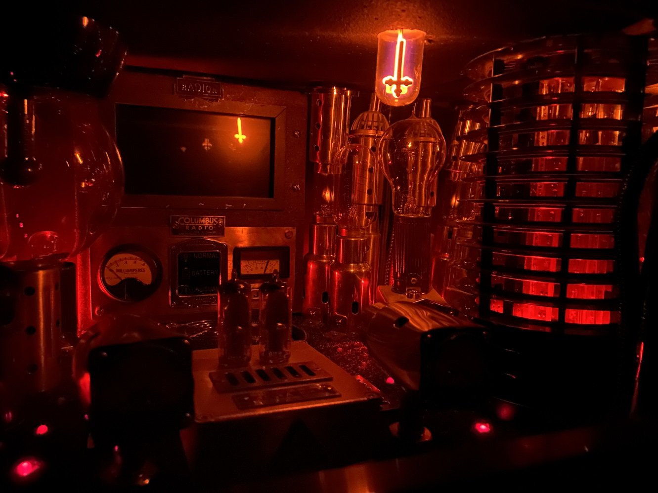
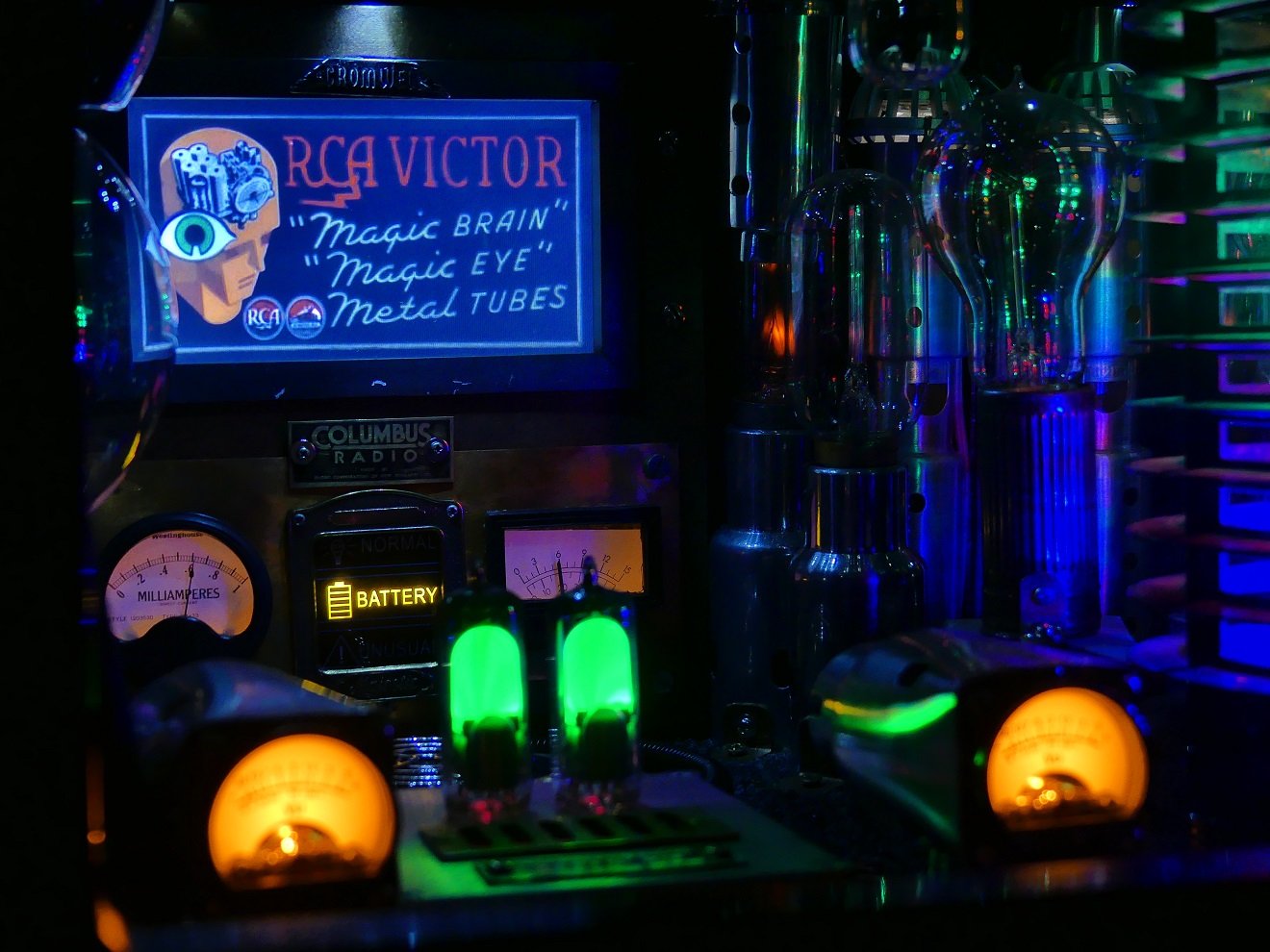
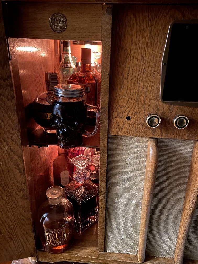
Go go gadget curtain: You can use the control panel to turn on and off various elements of my pointless box of lights to create different looks. Here's your basic 'starlight headliner' look: The slight glow from one of the orange neons is a bug 'feature', as is the fact that I positioned the Southern Cross constellation too close to the rear, causing its southernmost star to spotlight the 'Radion' logo above the TV. Turn on the analogue meters and the dancing Nixie tubes: Add the plasma globe, the TV (which normally can't be turned off - I unplugged it for the photos) and the neons: I deliberately positioned one neon bulb close enough to the plasma globe to show the induced glowing: Turn the globe off, put on its blue LED, turn on the incandescent bulbs behind it: I grabbed each variation of these vintage filament bulbs while they were still easy to come by. Now they're being replaced on the market by LED 'filament' bulbs, which just aren't the same. A side effect of these features is that the heat production / power consumption of my creation is a bit more than ideal, just like a real valve radio. Here's where the old micro system lives, in the side of the cabinet behind a cover that slides upward: Its display is very dim these days. If it ever looks at me funny, I'll replace it with something which can do CDs, Bluetooth and USB. For the time being, I use an aux cable. So yeah, you get the idea. (hail Satan) That's pretty much it. Slight variations thereof. I have run out of attachment space for this post anyway. I'll make a video at some point, and afterwards I'll probably only consult my pointless box of lights whenever I need a drink. Open bar!
7 points
-
Pics from the port in Kobe! All looks good, appears that the owner that flipped the car put new tyres on it which is a bonus. Due to leave Japan this week Two gremlins to note: - Car looks to be started up in the images as rev gauge shows 1500 rpm however the charge light is on.. - From photos I've just noticed that the chassis plate is also not in the engine bay. I hope this isn't an issue come VIN time, hopefully the TE27-XXXXX stamp on the firewall is ok on its own?6 points
-
Night stage lamps test fit... And coming together...5 points
-
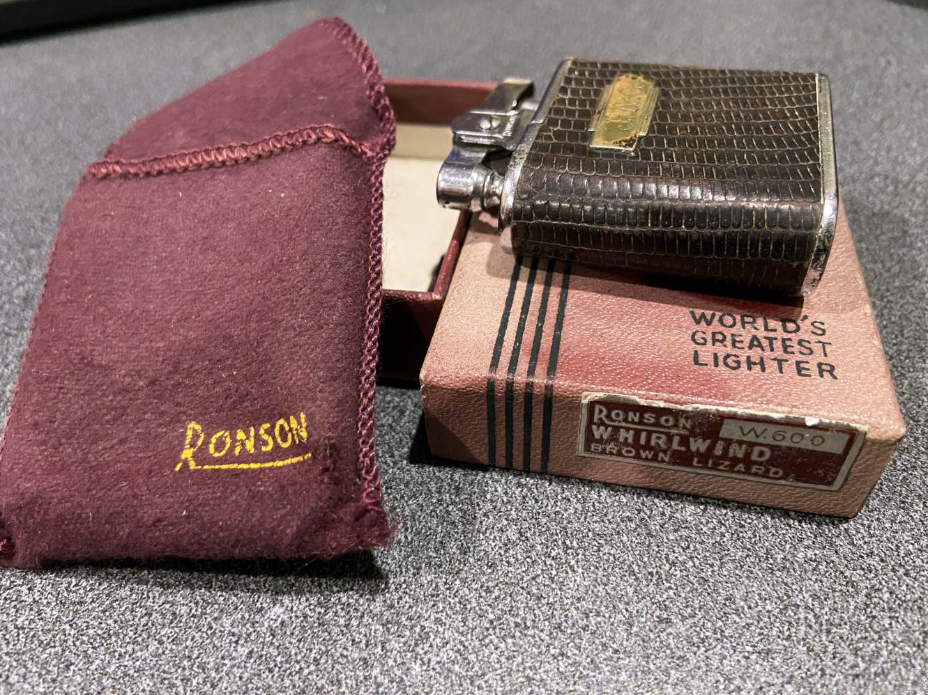
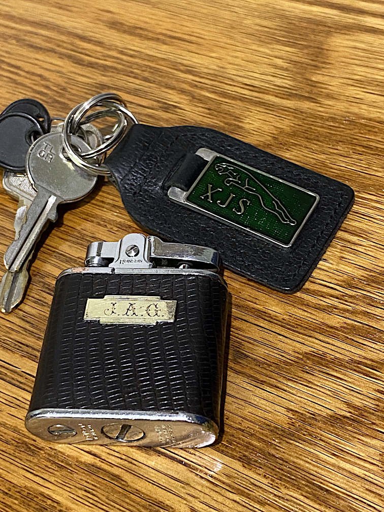
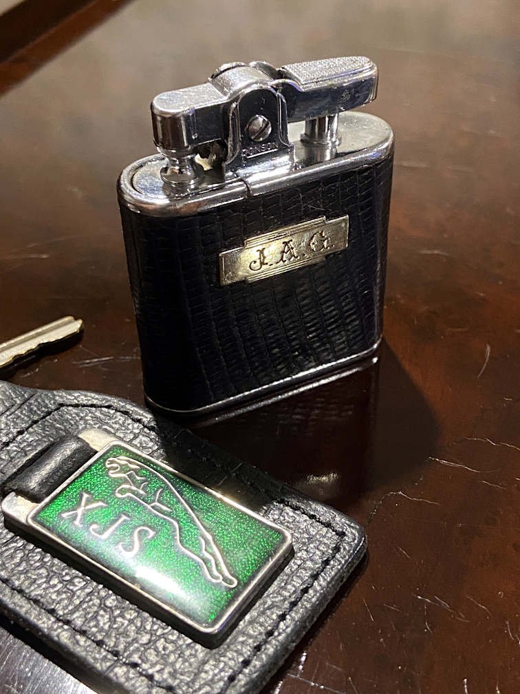
Check out my latest Jag-cessory: It's someone's scody old lighter, covered in 'brown lizard' and tobacco stains. But wait, when you clean it up, what does the engraving say.... Yep, it was once owned by Mister J.A.G. How good will that look next to my keys on the bar of the local TAB.
5 points
-
Nice LR! Dreams! Yup fair call on the un even ground and bulky! Plan is to throw a double bed in it for the two kids. Might still work out. Good point re sandflys! Was interesting trying to getting the LR level with its self leveling airbags yesterday (Corner Creek)
4 points
-
Maiden voyage beyond the end of the road today, I decided to take it to work, a distance approximately 5 times further than I have ever driven it. Some observations: It needs a 5th gear The tyre roar is harsh, possibly a consequence of polyurethane bushes? A rear wheel bearing is noisy The wheel alignment is terrible (expected) I drove home at night, the low beam is pants, high beam is good (need to relay the low beams) It looks comically tiny parked next to the corollas and swifts in the carpark. I like quarterlights as they are excellent wind deflectors with the window open. 90 km round trip acheived with no broken things!4 points
-
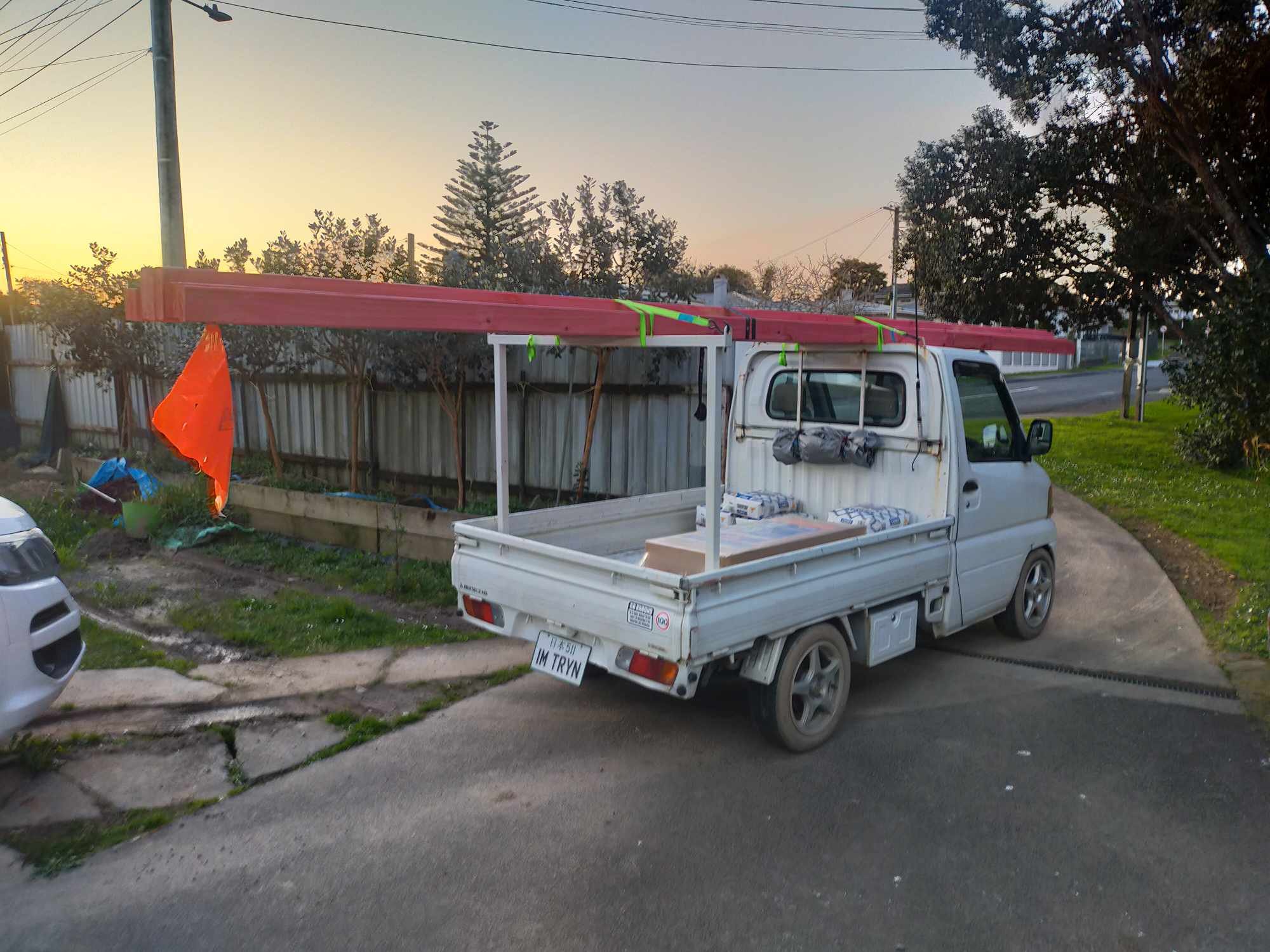
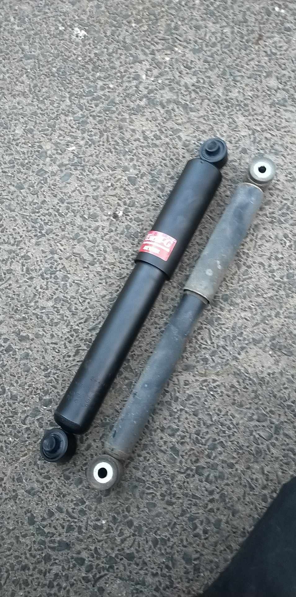
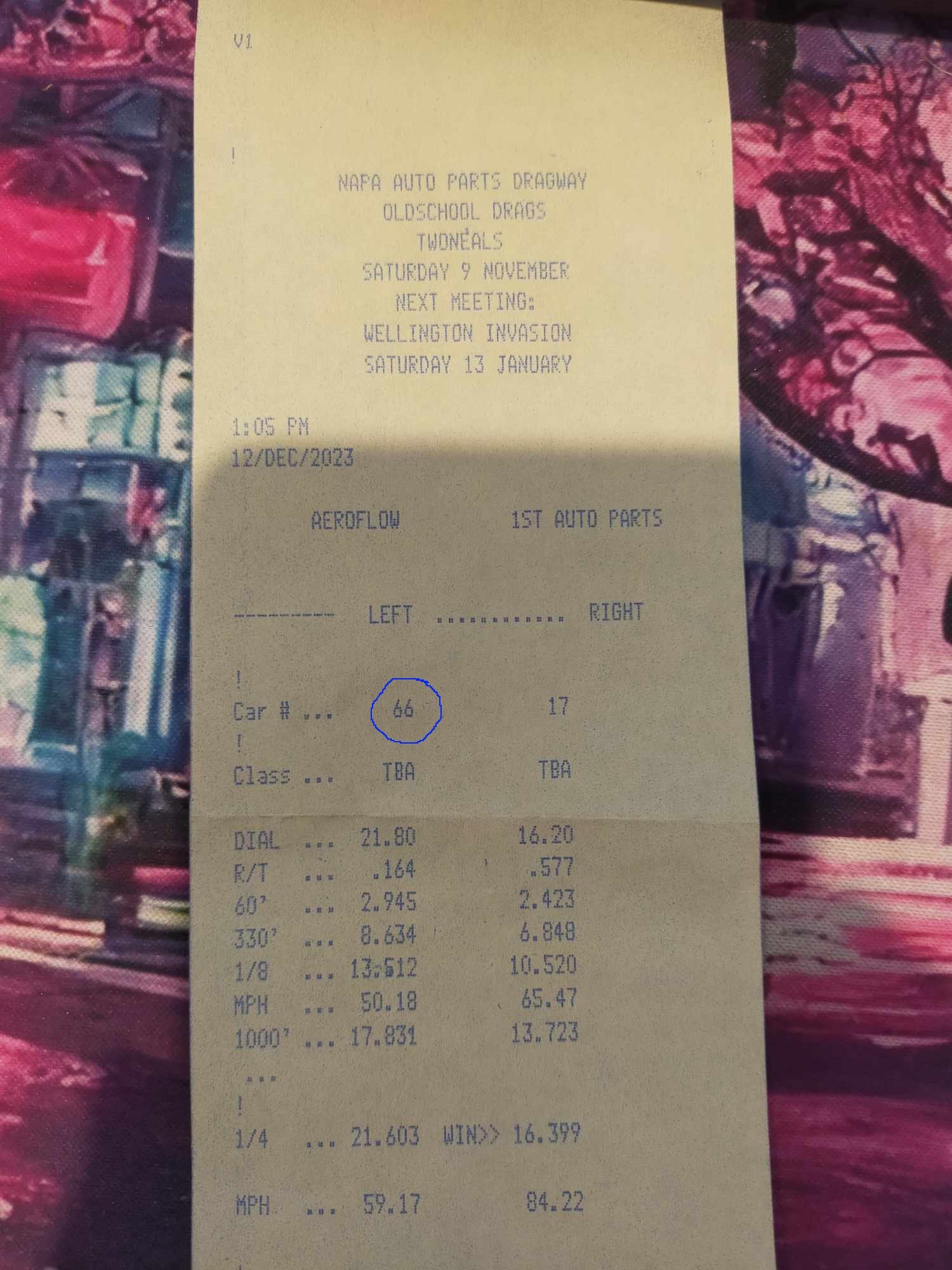
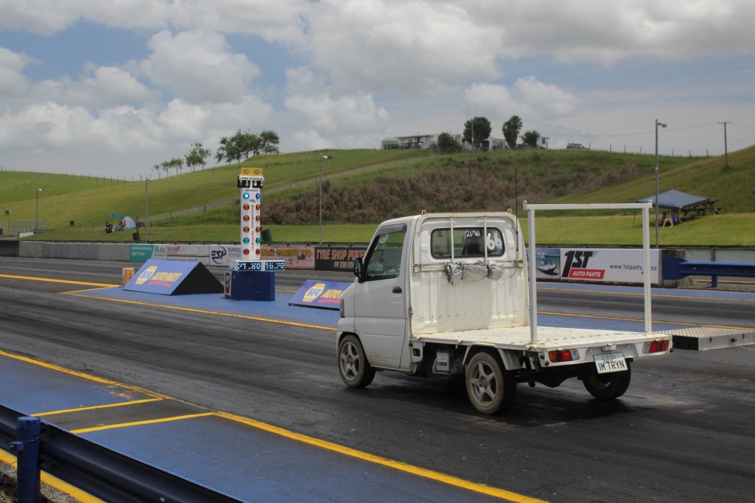
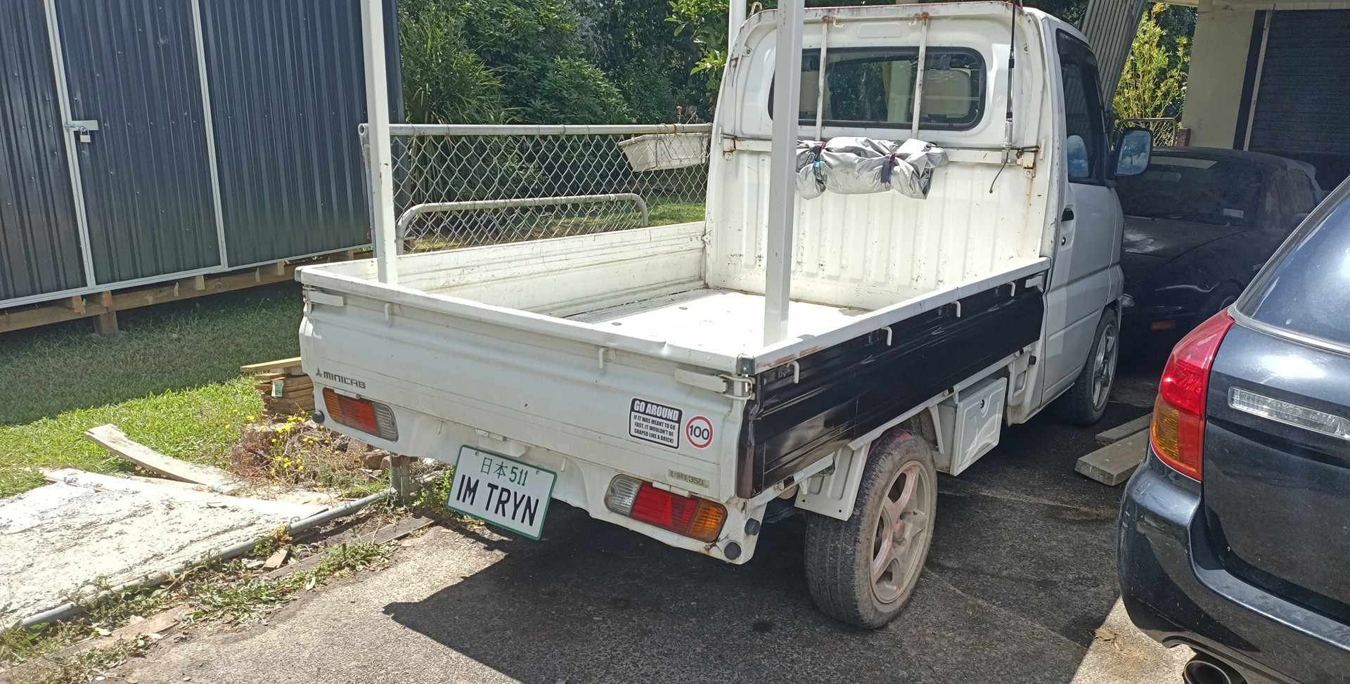
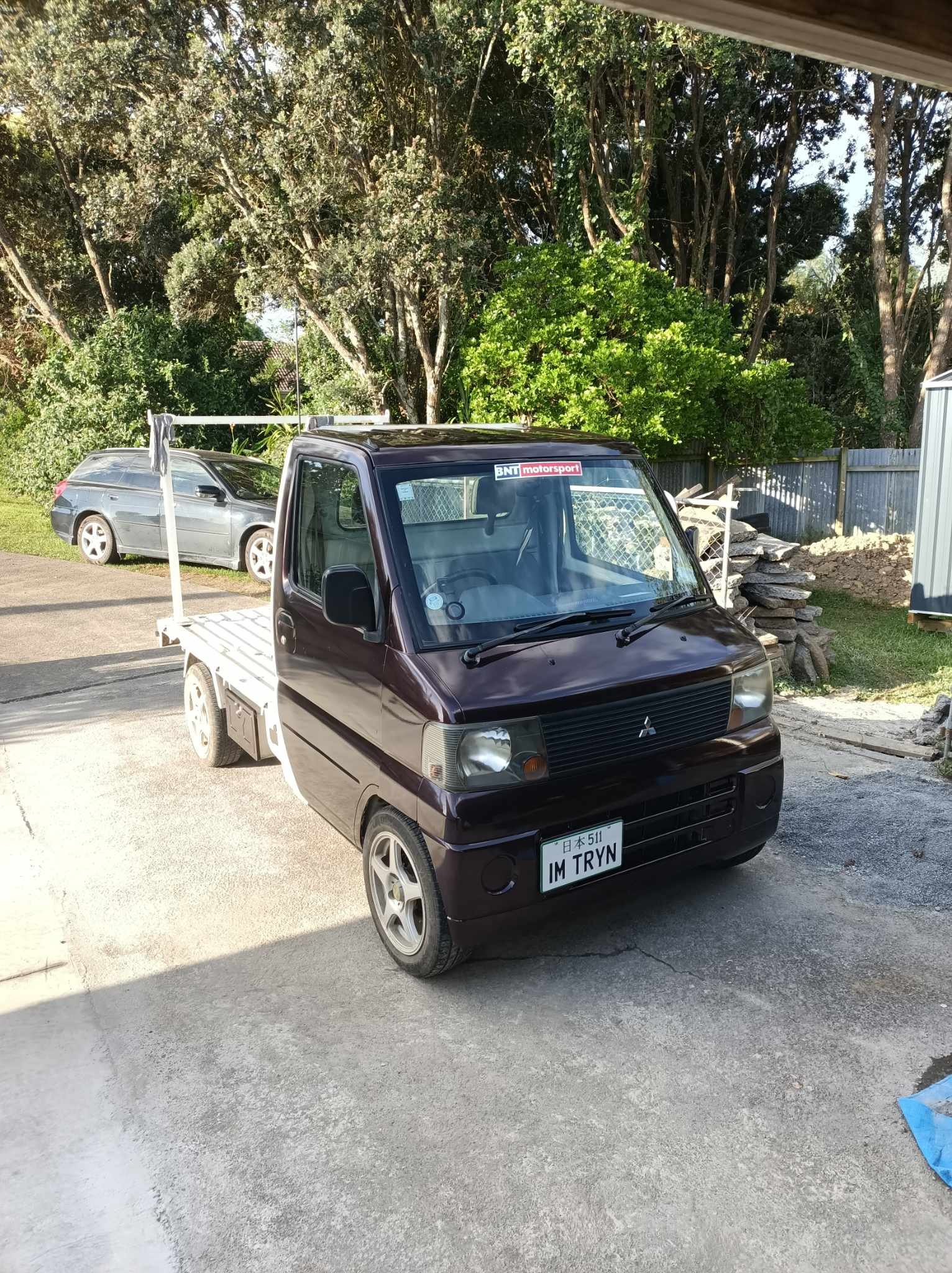
Been tinkering with the truck over the last few months in between picking up renovation parts. Scoured through the catalogs at work to find some replacement rear shocks. Fronts off a mid 80's Chevy Blazer fit perfectly, just needed to slightly increase the diameter of the crush tube. Mates invited me along to the oldschool drags where it got a best time of 21.60@59mph Over the xmas break finally started wrapping the truck with the wrap i bought around xmas the year before 1.5x6m roll of 3M Gloss Black Rose almost finished the whole truck, just got 2 bed sides to finish, and the smaller border of the tray. Will be using bedliner for the inside of the tray and back of the cab.
3 points
-
What a scorcher
3 points
-
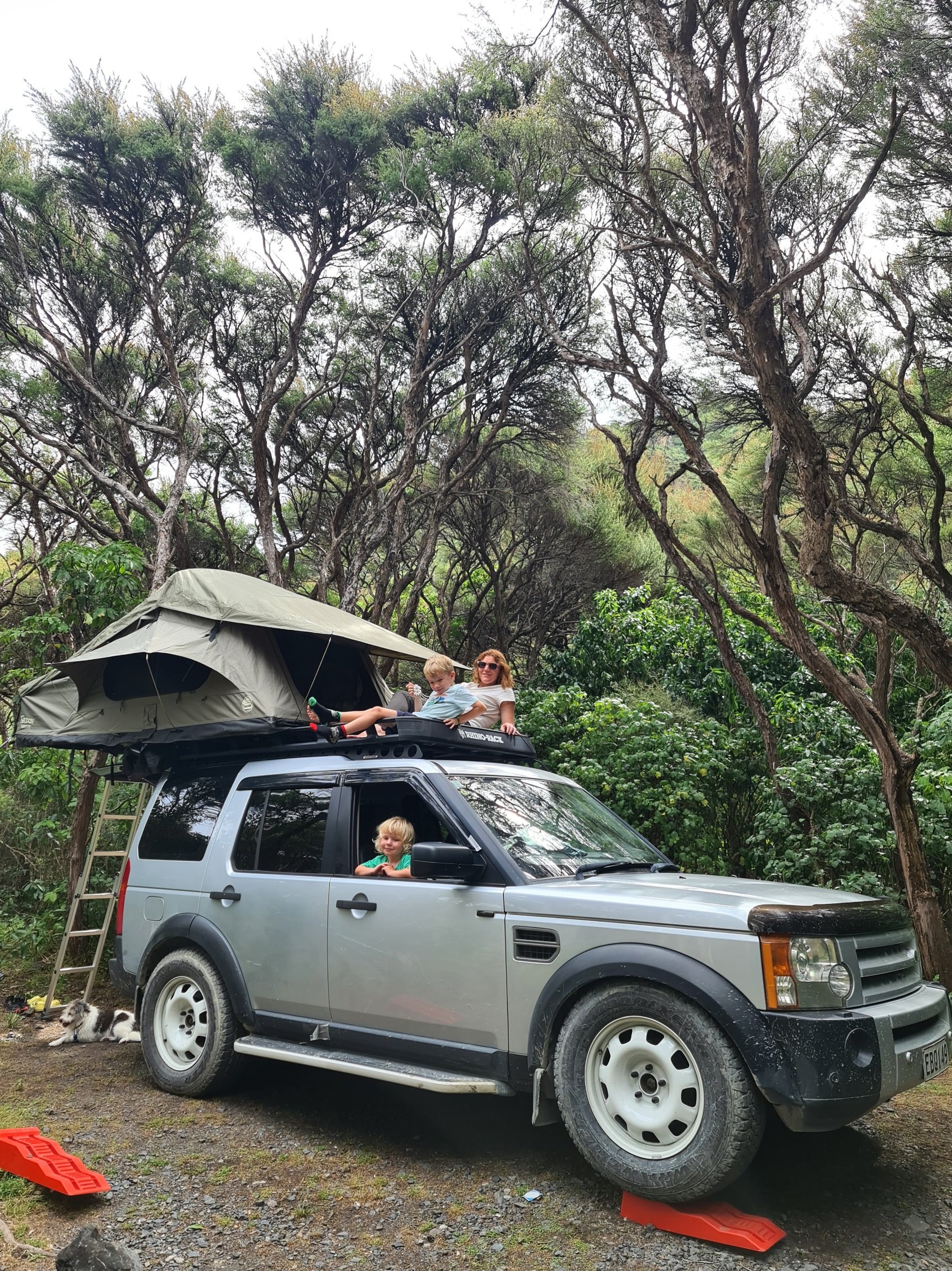
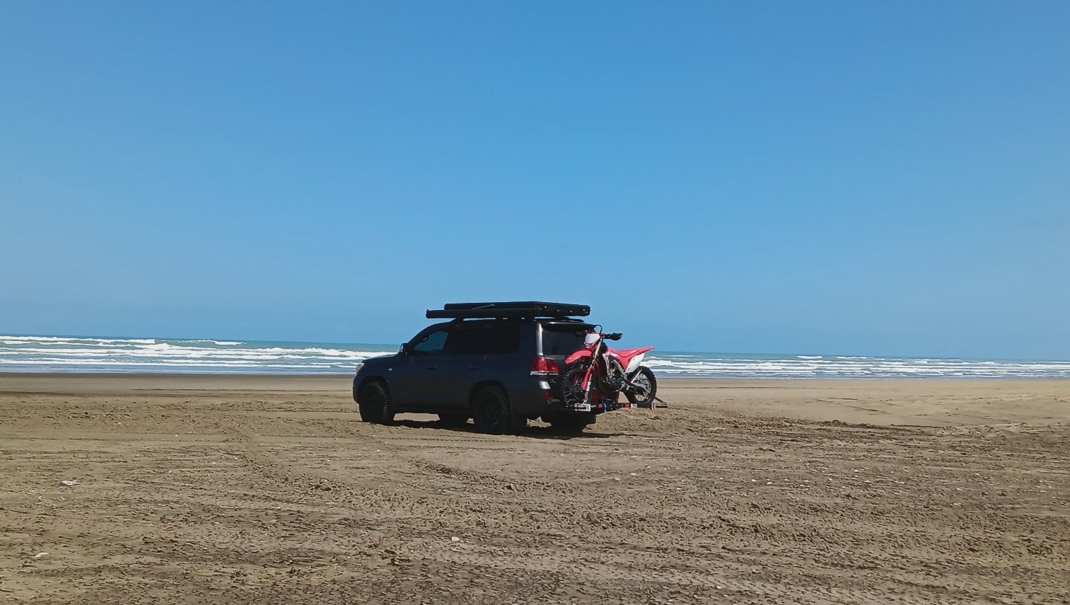
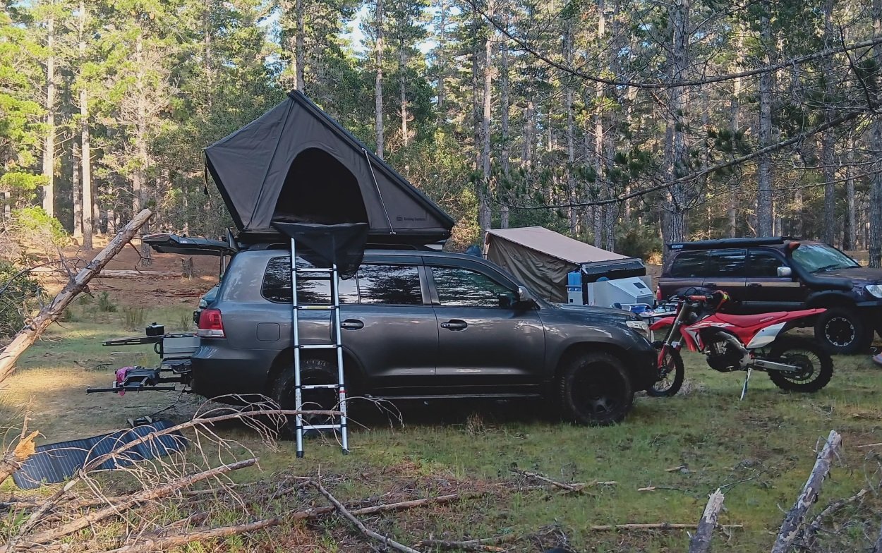
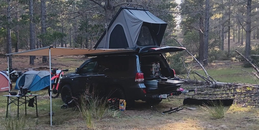
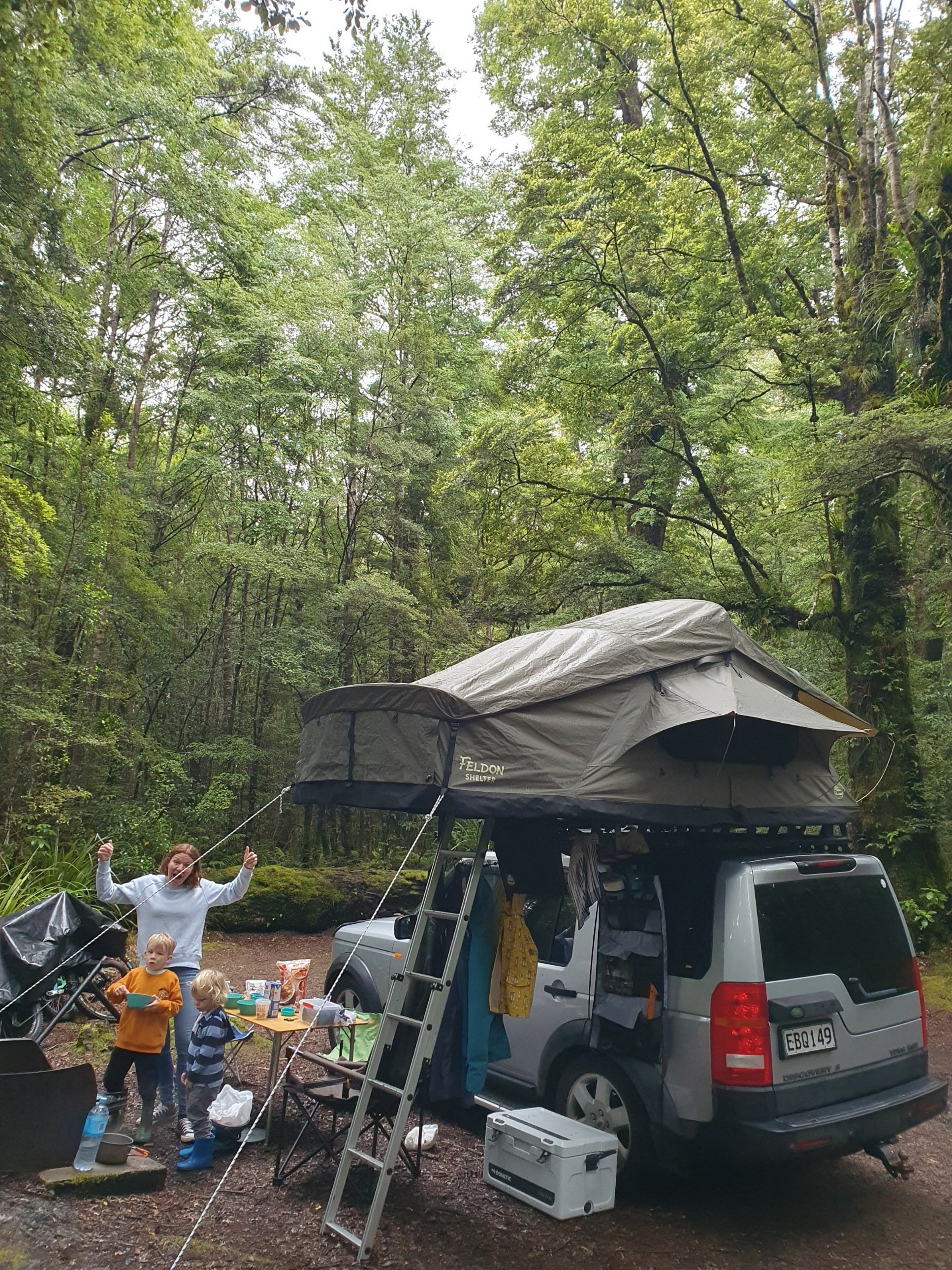
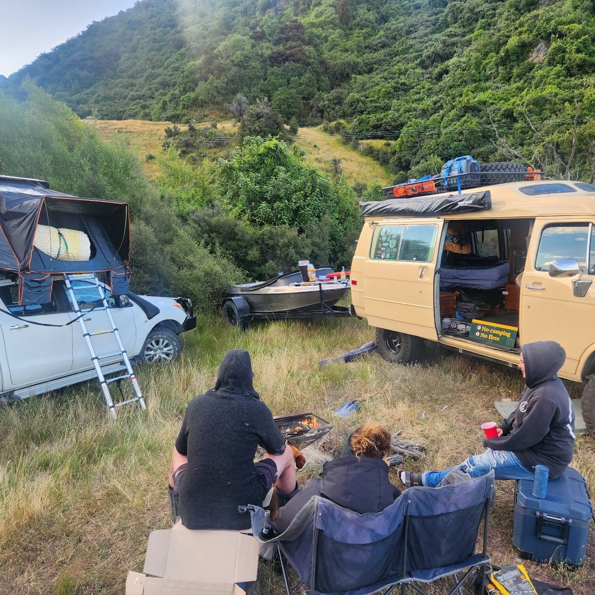
I'm real happy with my off road camping set up now I decided against dragging a trailer around off road can get more places with just a wagon too. Removing dirt bike setting awning and tent takes10 min,15 min to pack up everything so not a major for overnight stops. 12v system will do 4 days running fridge and lighting if staying longer ill set up solar blanket,basic gas cartridge twin burner for cooking and a jet boiler for a cuppa. Rear draw system keeps everything organised. Don't have to pay extra for length on ferry crossing Diesel v8 doesn't even notice the extra weight,truck telling me I'm using extra 1-1.5 litres per 100km compared to normal and dont have to do reduce towing speed on open road
3 points
-
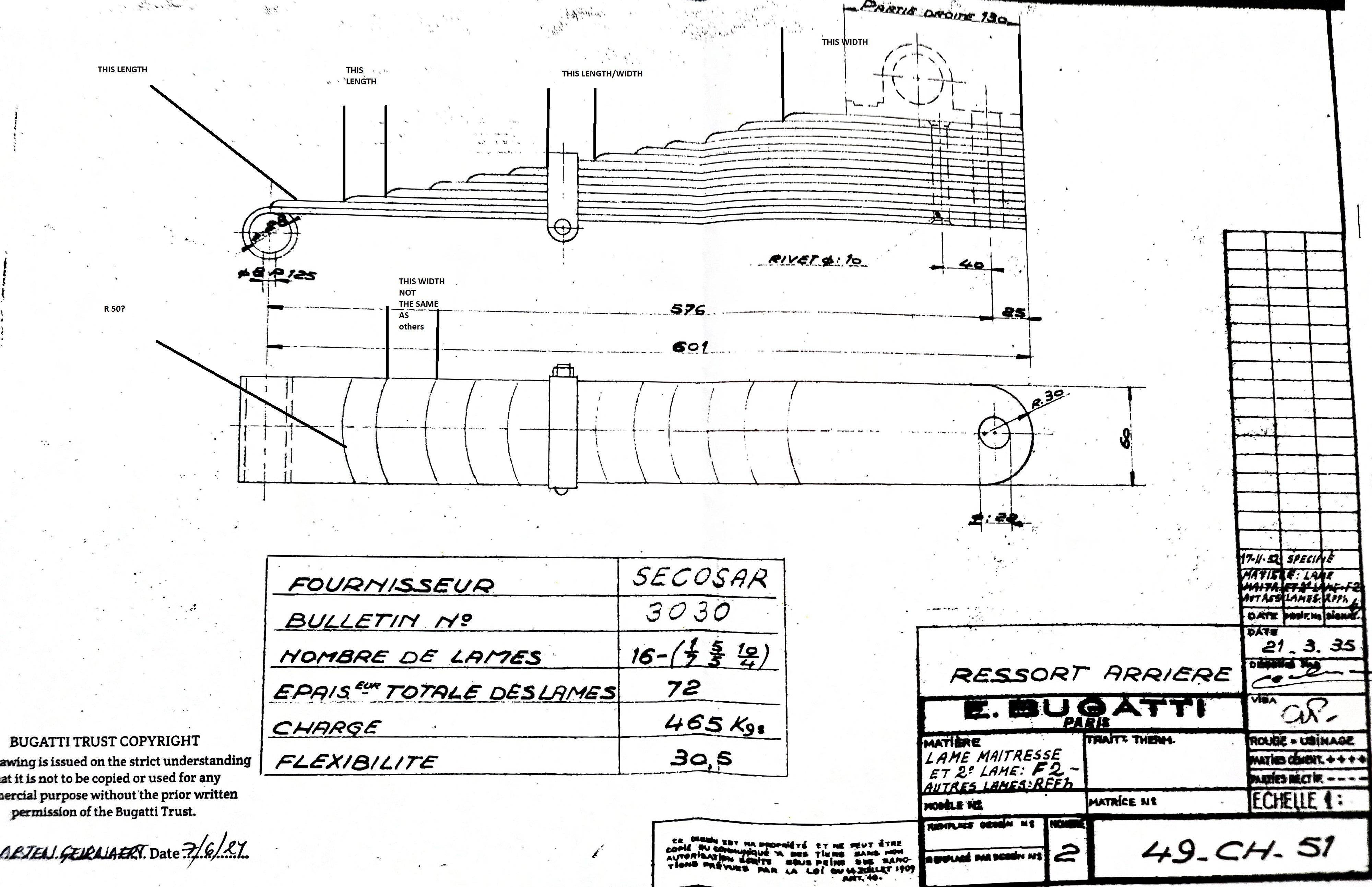
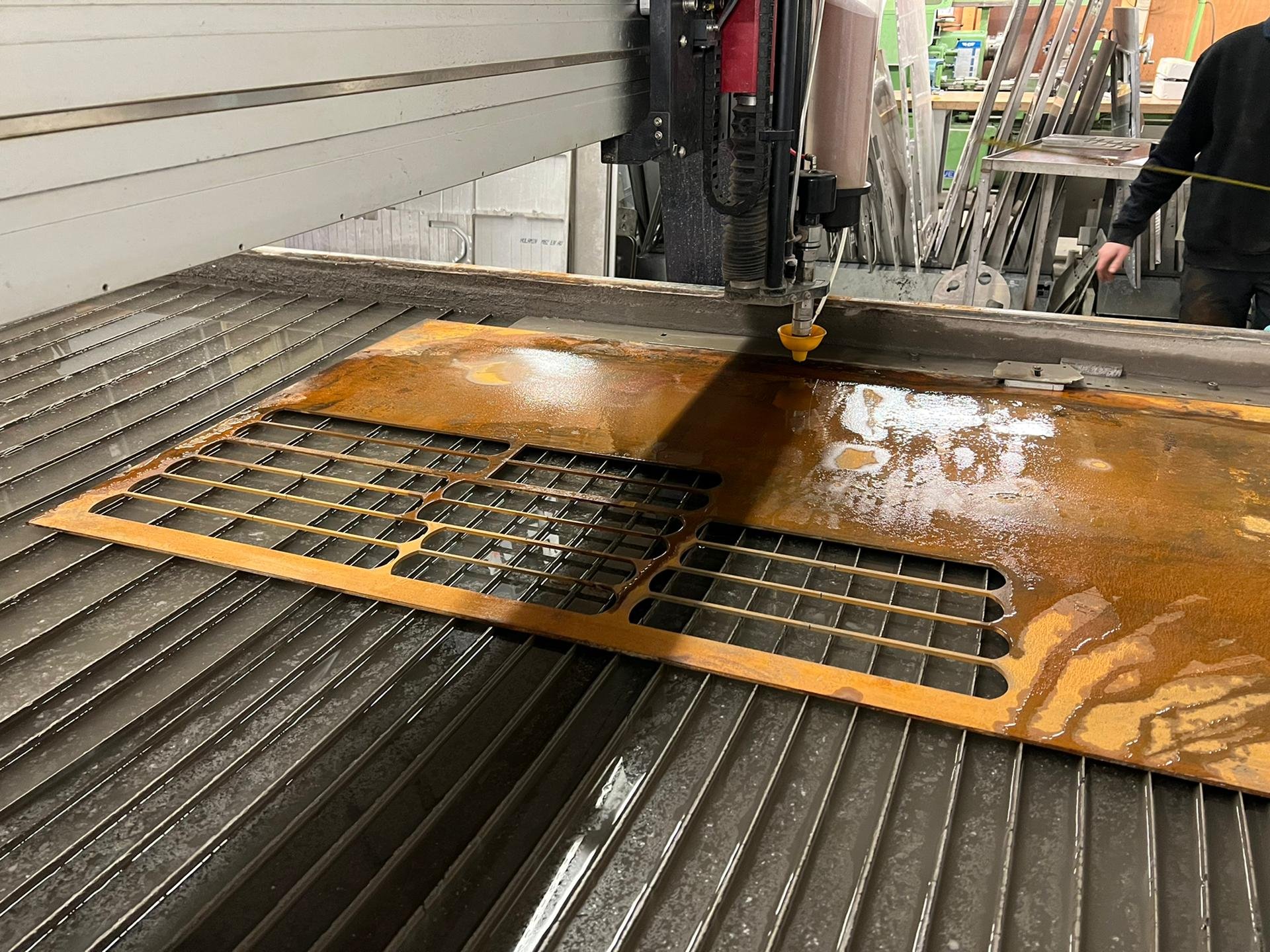
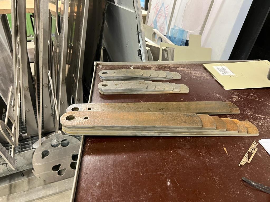
Rear Springs: My original rear springs are typically Bugatti in format: a forward-cantilevered quarter elliptic multi-leaf array. The springs in my 2 sets were pulled apart, and they showed heavy rust pitting to the extent that they were not going to provide reliable suspension without cracking or breaking. So, we decided to get new springs made. There's a place in countryside Victoria that specialises in re-fabricating new springs for old cars, and when they examined one of my spring-sets as a sample, they went "Yeah, yeah, yeah, nah." It was going to be too much work! A bit of internet research alerted me to a specialist in the wilds of Wales, but he only does work when requested by Tim Dutton, and he was on the verge of retiring. Then I found a chap in Belgium who had just finished making new front springs for a Type 55 - he posted a short video of himself jumping on them and bouncing around - a I figured that we had found the right guy for the job. There was a bit of to-ing and fro-ing involved: the original array for the T49 springs is 1 leaf @ 7mm, 5 @ 5mm, and 10@ 4mm. No-one, anywhere, has access to suitable 7mm thickness spring steel. We got spring engineers and gurus involved, and ended up with a revised recipe for the leaves in our spring array: 2 leaves @ 6mm, 4 @ 5mm, 10 @ 4mm. Same overall depth to the spring array. A Bugatti factory drawing showing the original rear spring array dimensions. This gave us a good specification to work from. The process of fabrication, further machining, bending and tempering took way longer than expected, as a result of lockdowns and a cardiac crisis from the spring-bending consultant, but finally the 2 spring arrays were completed and assembled. In this pic, further radiused bevels are yet to be cut into the nose of each leaf, and then they get curved and tempered to suit the specified load and deflection.
3 points
-
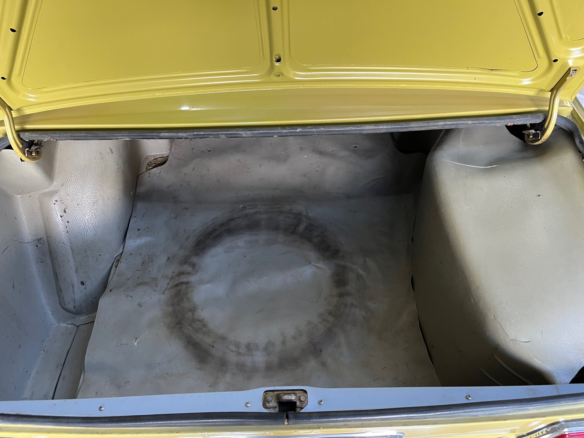
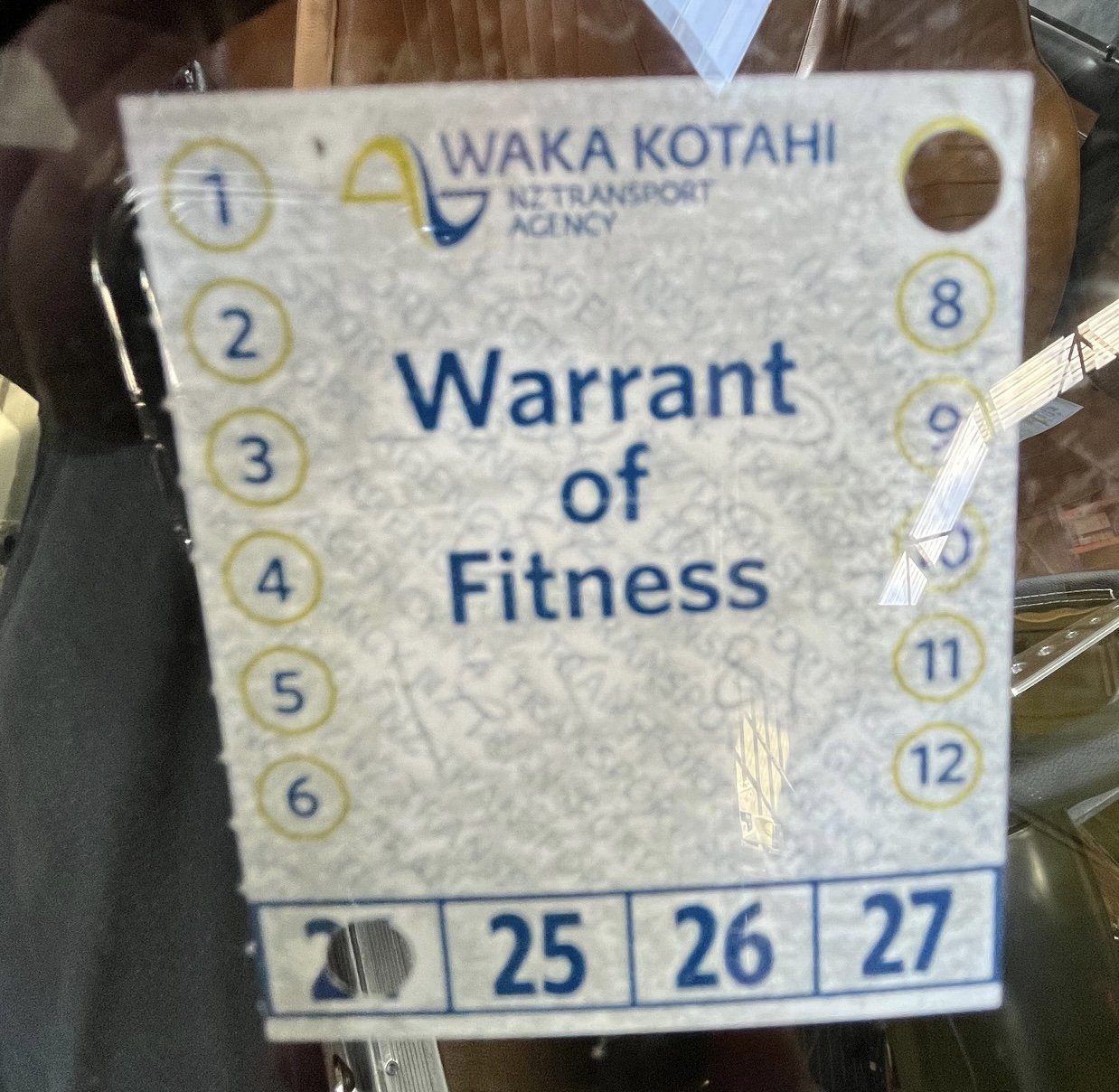
Did a couple more things this afternoon after work. I borrowed the fixed fan off the 1500 while I decide how to proceed with an electric fan. She’s tight down there… Then I flung the boot linings back in. And then I went for a drive to a place… And got a special sticker for my troubles… CLEAN SHEET!! First WOF in 15 years. I’m feeling pleased with myself and am looking forward to a celebratory beer with dinner.
3 points
-
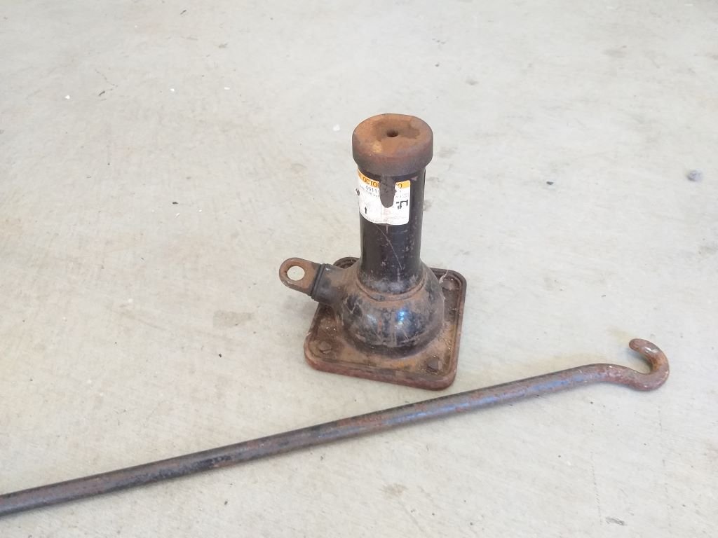
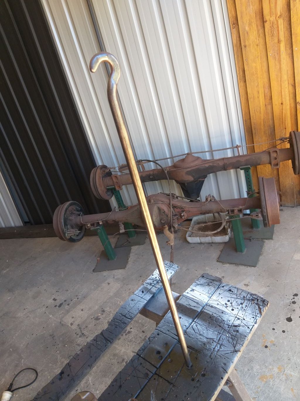
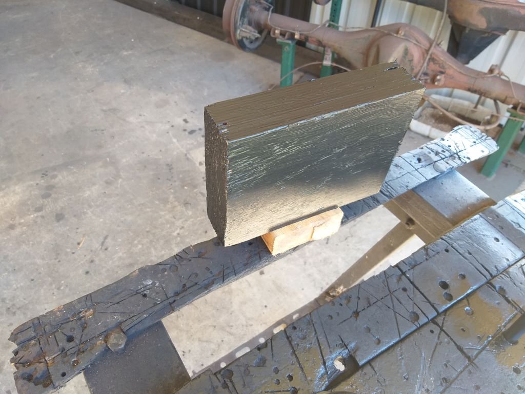
Okay, so having a spare wheel doesn't really help if you haven't got a jack ... duh. So today I thought I'd remedy that situation. Rummaged through the pile of leftovers from my donor vans and I have a choice of two scissor jacks and a bottle jack. I'm not a fan of scissor jacks so the bottle jack got the nod. Pulled it out into the light of day. Looks a bit crusty but it does come with a crank handle that looks just as crusty: First step was to check that the jack still functions and that it has enough bottle to lift the Thames (did you see what I just did there .... absolute howls of derisive laughter Bruce) Grovelled under the van and it will lift either of the back wheels perfectly. Tried the fronts. Bottle is too tall to use under the front beam. Bugger. Scratched my head a bit then decided to try using my strut rod mounts as the lifting point and she lifts a wheel, but it's just on the borderline and I doubt that she is high enough to get my commercial profile spare on. So I grabbed a bit of timber which will make a solid base for roadside lifts as well as giving enough lift for the front. Perfect. With the functionality box ticked I then focused on the aesthetics. Took to the jack and the handle with my wire wheel of death and it started looking a bit better: Quick wipe down and a spritz of the usual satin black. I even fed my OCD by giving the wooden block a few coats of flat black fence paint. Tomorrow I'll work out a nifty way to store everything, so it doesn't rattle around in my storage compartment. Thanks for looking.
2 points
-
Well done. So much wasted time. So awesome. I love it.2 points
-
LOL! I just got a tf035 from a 1500 Mivec Colt at pickapart yesterday for my 1300 nissan engine mini thing.2 points
-
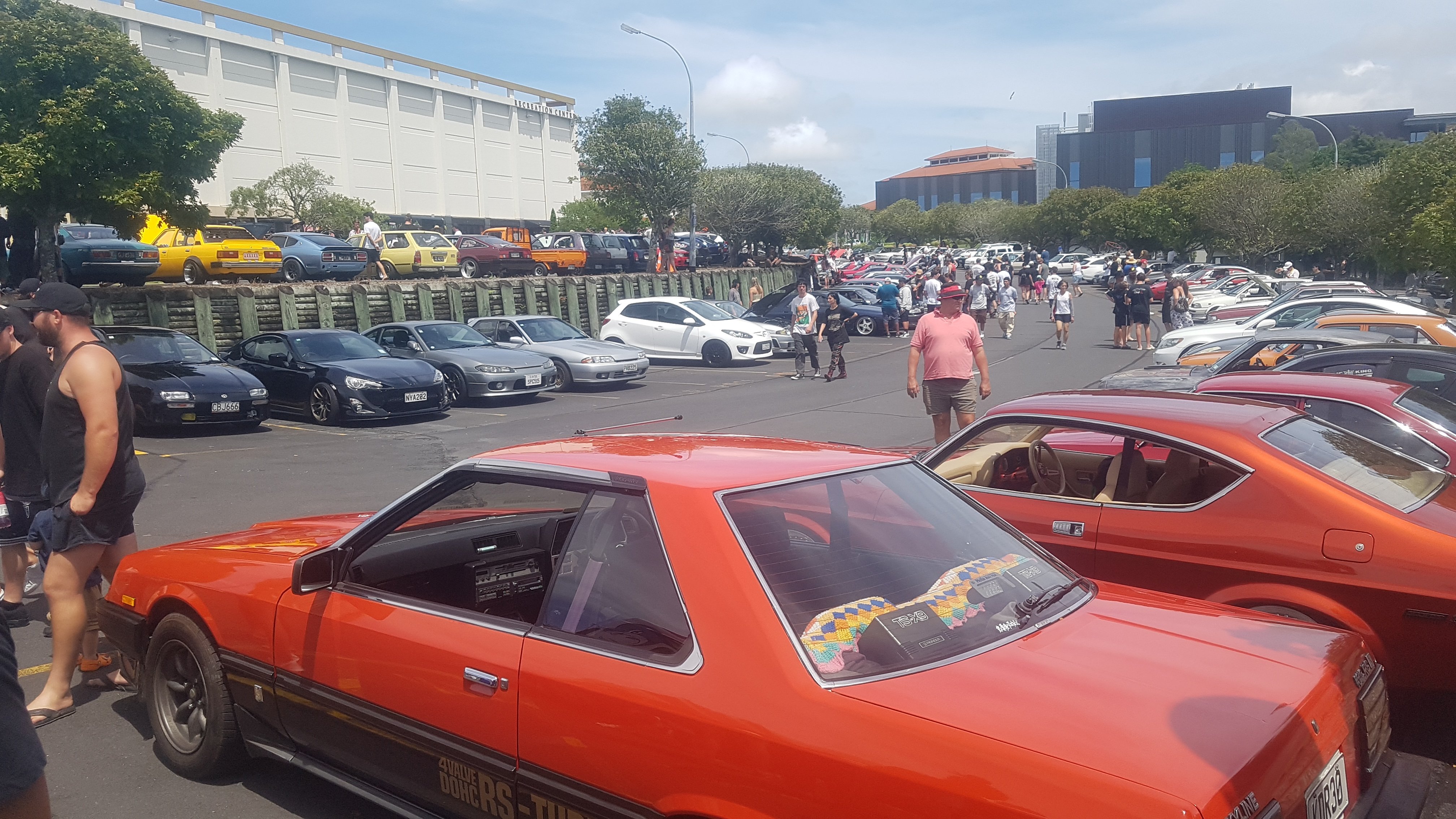
Went for a warrant and failed on the front left wheel bearing. Got a warning last time so fair call. It'll be fixed this week along with the rear suspension. A little wary about my new power steering lines. I had fitted some heat sheathing as the original lines were burnt and the new line is probably not fire proof but this seems to have some damage now. It only contacts at full lock so hopefully it won't be a problem but I have put some ally tape on the area for some extra protection. Ally tape fixed most problems. Took the Mustang to Kumeu, don tell the fuzz. I wanted to get it out a few times for 'testing/shakedown'. Bloody good event this year. Hotter than the face of the sun but the shady bar was good.
2 points
-
I also did the vcc Pomeroy trophy out at ruapuna the other week along with @Sanfiddy and (/insert jareds handle ( /I don't know what he is on here )). Driving tests included a standing 1/4 mile, a flying 1/4 mile, a braking test, a slalom test, and a 20 minute high speed reliably test on the reace track trying to achieve a set number of laps given from a convoluted handicap formula Got taxed pretty heavily due to 6300cc of engine but otherwise made 9th out of 29 in my class . Managed 115mph at the end of the main straight and with 80s competition brake pads never ran out of stopping power either . Which was a miracle having to stop 4400lbs of car
2 points
-
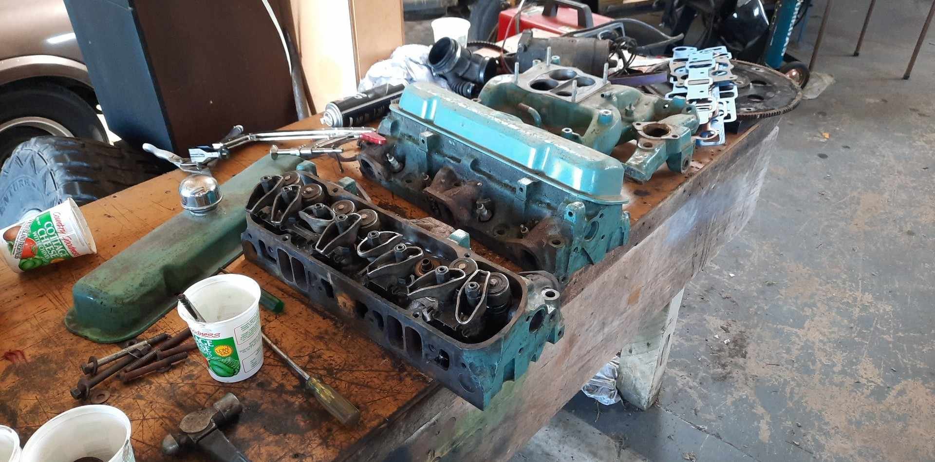
I've also got the heads and intake manifold and holley 650 double pumper that the old man had ported in the 80s and ran on his 455 so they'll get a set of k liners in the guides and a clean up . Hopefully don't need new valves but we'll see
2 points
-
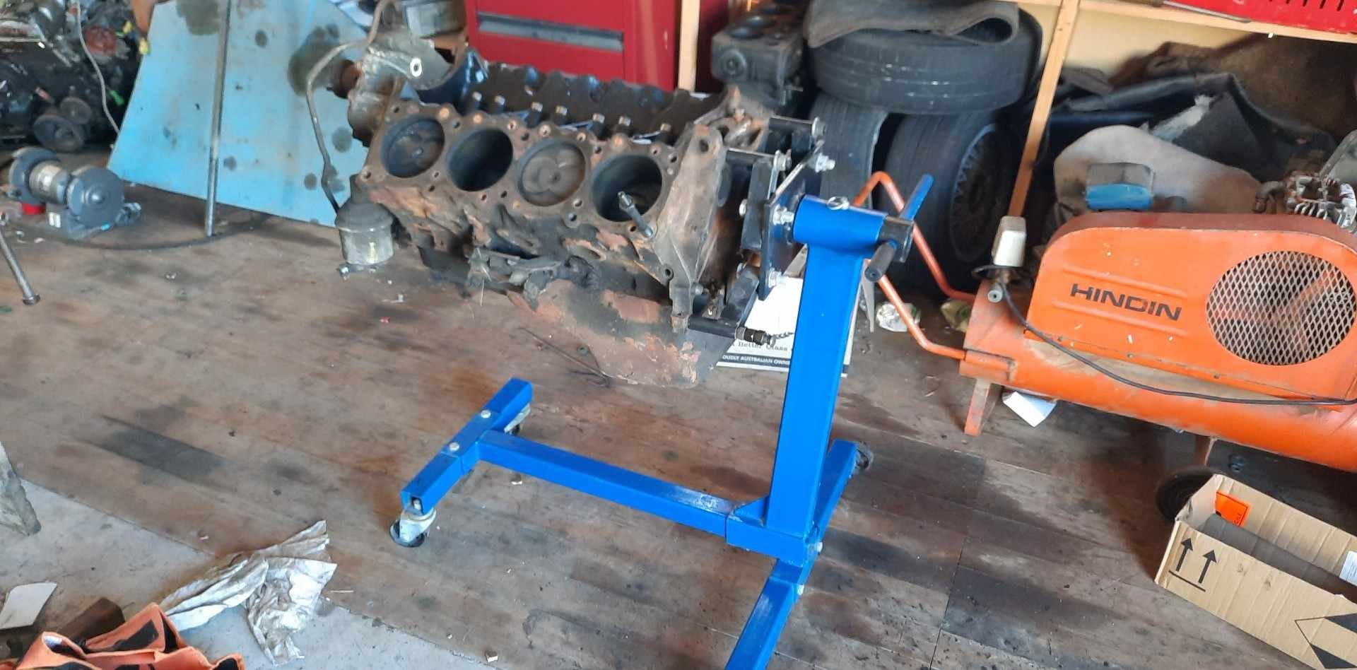
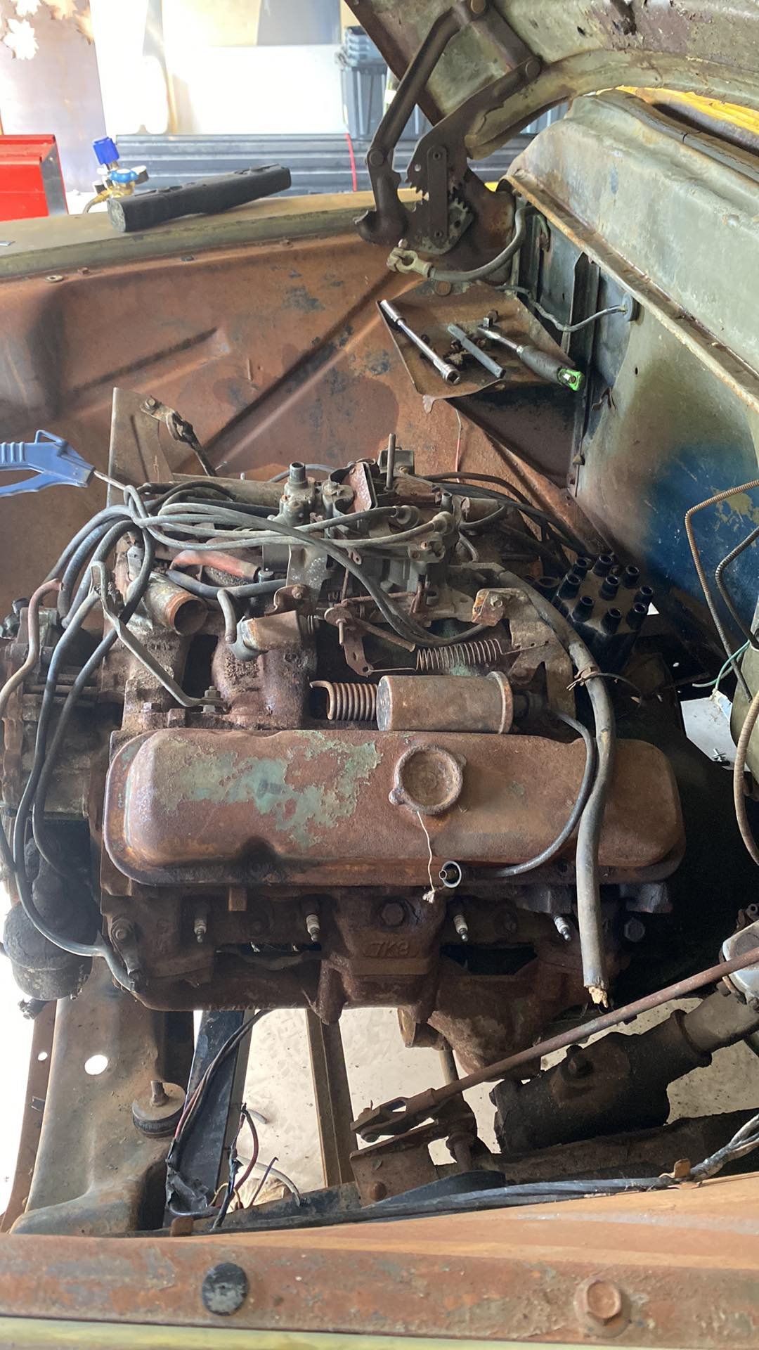
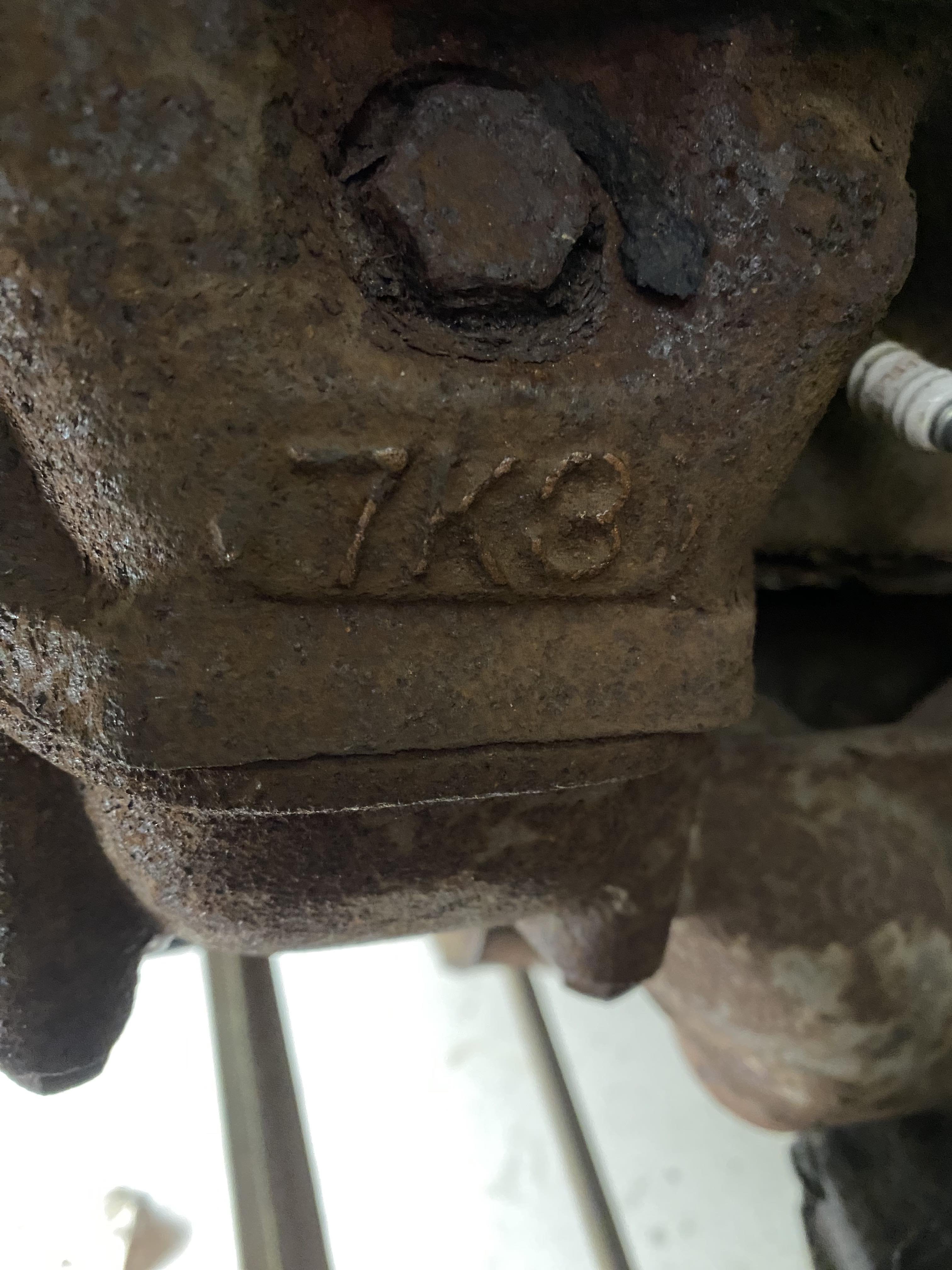
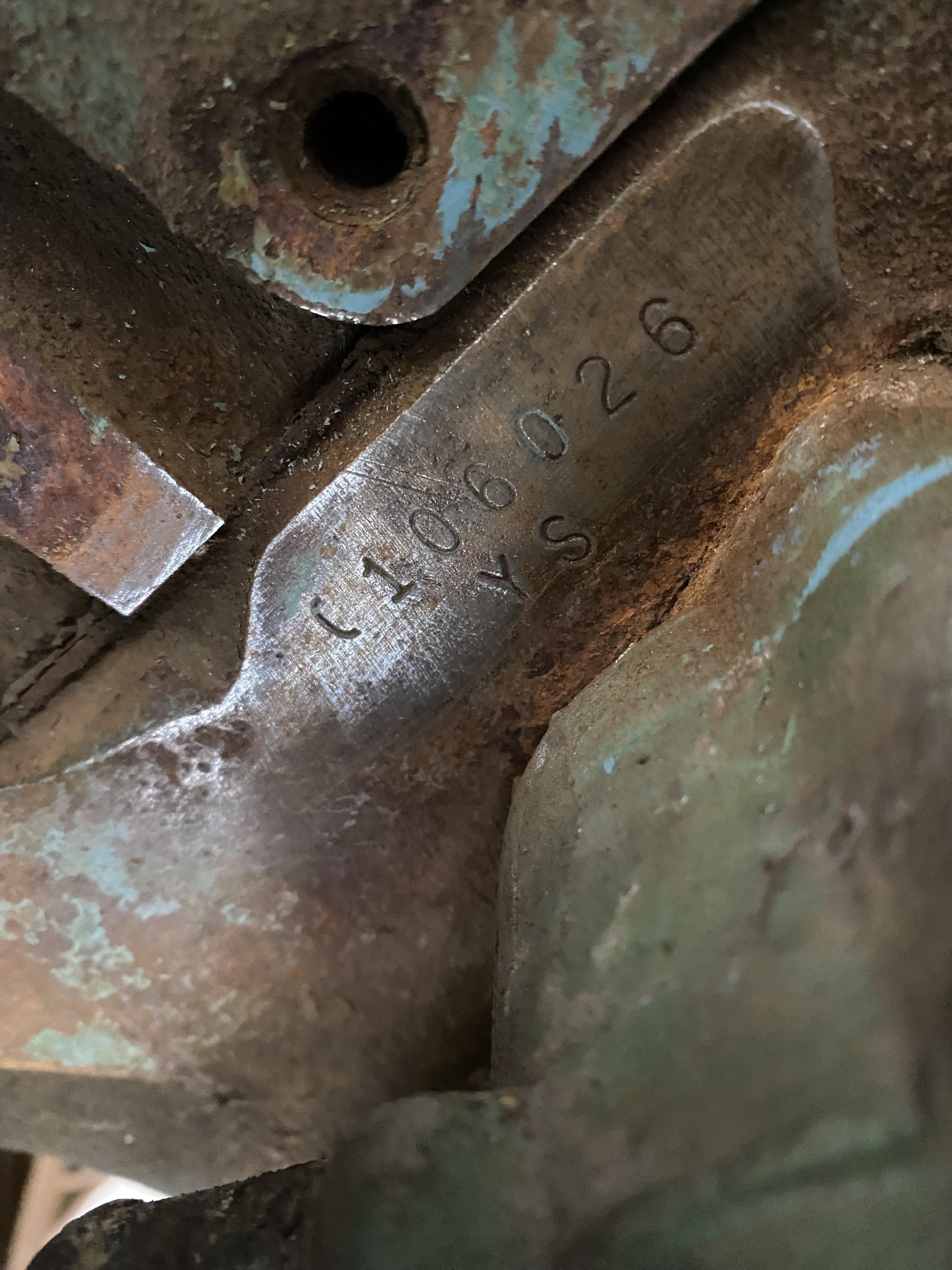
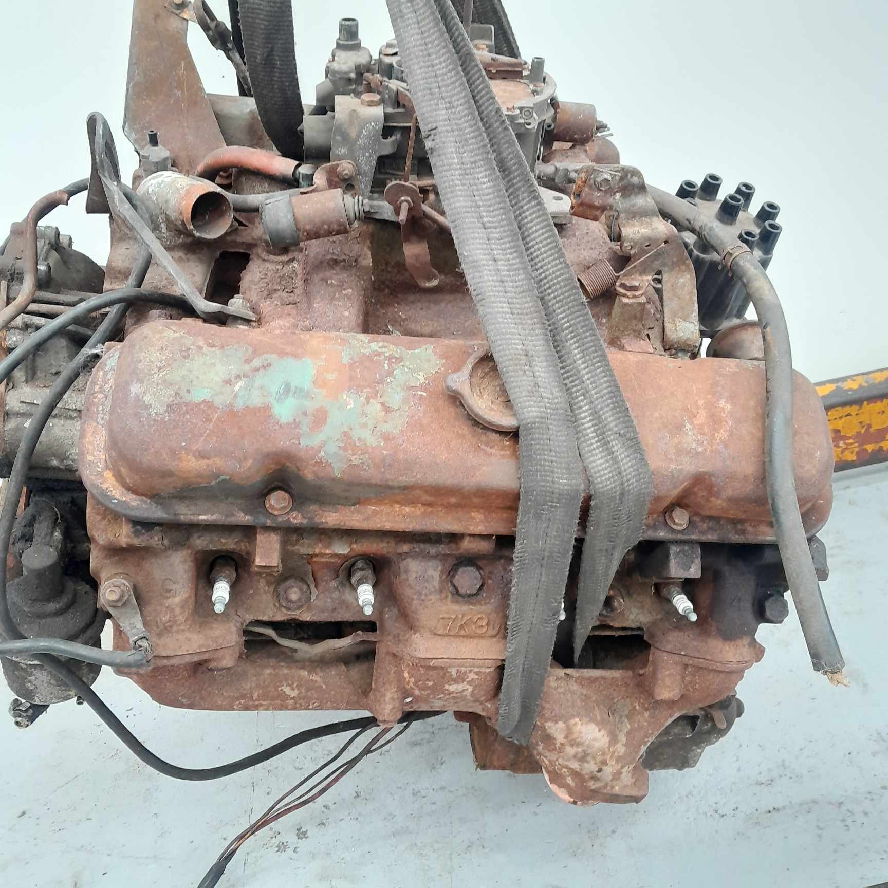
So @Carsnz123 send me a message November about a pontiac 400 in Hamilton. I promptly sent the seller a message and it turned out to be a 1972 400 with 7k3 heads and the original q-jet ontop. Sparked a deal and then @Beaver did me a solid and picked it up and stored it for a few weeks till john at south island couriers did a north island run and he picked it up and brought it down to chch 2nd week of December rolls around and I've got covid and I get a call from John that he's gonna be in town tommorow. Cunt . Had to call another favor from a workmate to u load it and store it at work till I could come get it in a fortnight . Finally actually saw the motor I'd payed for over a month prior on the 22rd of Dec Got it home and pulled both heads and from best I can tell it's never been opened up till now. Its not up on a stand waiting for some more time to strip it 100%
2 points
-
Going to give the extension room a go this weekend
2 points
-
Same here!, wish got one yearz ago!
2 points
-
oh my god I am dealing with that guy currently, he chimed in and gave his not asked for two cents when I asked how people were going with either Tein S.tech or Megan racing lowering springs in their GTOs and he said they should not be lowered and that the factory springs and shocks are just fine, especially on the track.2 points
-
I suppose I better start with the obligatory acknowledgement of the extended time between posting... Cool so with that out of the way, I started to make my first little bits of progress at the new house. And in the theme of progress, I figured the best place to start would be going backwards and redoing work I've already done. It started (as many bad ideas do) with me standing and staring at the car for a while. The more I looked at the radiator mounts and installation, the less I liked it. The top hose port of the radiator is above the fill point, and the big notch cut out of the lower cross member is just silly. The proximity to the engine also doesn't leave a lot of space for fans etc, and overall, the rad is just excessively big. So, what to do about it? Firstly, I decided to look into the engine to rad proximity issue. I went back to the very basics. If the gap is too small, why is the engine so far forward in the first place? Is the distributor too close to the firewall? Well, no. I'd assumed from the beginning that I'd remove the dizzy and either run batch fire or pick up a cam signal from the front of the engine with some other aftermarket solution. Ok, what about that IACV? Isn't that in the way? Yeah, it kinda is. Right, so why is it there? Do I need it? For these BMW throttles, yeah, if I want the ECU to be able to control the idle RPM. Ok, do I need these BMW throttles? Yes. ITBs for me are a hard requirement for this car. Sure, but do I need *these* BMW throttles? Well, no, not necessarily. @Roman and followers might see where this is going. Ok, so if I take the intake manifold and throttles off for now, then what is holding the engine forward? That would be the thermostat housing. Being as it is a FWD engine butchered into a RWD layout, the thermostat housing is now about as far from the radiator as it is possible to get. This is inconvenient from two perspectives; it means the coolant has to return from the radiator past a set of hot headers, and it also means the engine is held forward artificially in the engine bay. Right, so does the thermostat housing have to be there? Well, again, not necessarily. It's only at the back of the engine thanks to a long transfer tube that takes the coolant from the thermostat to the pump inlet through the valley. If I can figure out a way to get rid of that tube, I should be able to shift the thermostat housing to the front like a civilised engine. So I had a look at what that might take. The factory pump inlet is fed by the cast adapter on the right hand side of the above photo. I found that by removing the transfer tube, that adapter could be spun 180° to face forward and still bolt up just fine. Great, good start. The next big problem is the cam belt. (If you'll allow me to borrow someone else's photo for a minute) You can see how the belt path runs more or less directly through where the new coolant housing is. To get around that, I bought a cast aluminium elbow to get the tightest bend I could, then sliced the female O ring sealing surface off the pump inlet adapter and welded on the new elbow. To finish it off, I needed to make something to allow the thermostat to sit up inside the new elbow and do its job. Initially, I cut the flange off the factory thermostat housing, and tried welding it directly onto the cast elbow. This was a disaster. A combination of my severe lack of aluminium welding experience (this is my first time using the AC mode on the welder in anger), and a potentially dodgy casting made for very fizzy welds that mostly resulted in a goopy mess rather than a nice sealing flange. So I cut that off and tried again. This time, I turned up a new flange and tube stub out of a big chunk of scrap from work. The combination of nice fresh material, and my slowly improving abilities made for a much better welding experience this time. Even with the elbow though, it still wasn't enough to clear the belt. To make the clearance required, a section of 3mm sheet was cut and bent and grafted in to create a small notch. Note I've given quite a generous clearance gap here. I've seen how much these cam belts can flap under high load/RPM, and the last thing I want is to strip the teeth off the belt, or crack the housing or what have you from the two of them coming together. I was careful to ensure the cross section of the narrowest point was greater than or equal to the next smallest restriction upstream to try and reduce the chance of cavitation or overheating due to restricted coolant flow, but I suppose I won't know how successful I've been until I can actually get it running. Finally, I needed to provide a return for the heater core coolant supply. I cut supply female O ring boss off one of my spare coolant housings and welded it onto the back side of the pump inlet adapter. This will allow me to use the heater core supply tube from my spare engine as a return tube for this one. So then we have the final result: A slightly modified factory return tube can be used for the bottom radiator hose, and the top hose can connect directly to the standard top housing. I took the finished product into work and hydrostatically leak tested it to ~5bar (5x higher than the maximum allowable coolant system leak test pressure in the factory service manual), as well as leak tested it underwater with helium to make sure there were no pinhole leaks. All seemed pretty good to me. So then a bit of a debrief: The modifications should allow me to move the engine back about 60mm before more extensive firewall modifications are required. This will have numerous advantages. - More clearance for a radiator and fans - A rearwards moved shifter position (I was never totally happy with the stretch to reach 1st as it is) - Better sump capacity thanks to more clearance between the cross member and the rear bowl - Better intake manifold clearance thanks to the slope in the factory bonnet. The updated coolant path will also clean up the engine bay somewhat, allowing better clearance for the headers on the passenger side. As far as what I might have lost from changing to this setup, the factory thermostat is an automatic bypass style which blocks off the heater core and recirculates the coolant around the block until the thermostat opens. My new housing does not do this. To make up for it, I intend to use a bypass style heater tap from a early 2000s Commodore to control the flow through the core, and thereby control the heat itself. This will mean I can turn the heater full cold during startup to manually cut the heater core out of the coolant path and hurry the warming up along, or if I'm really desperate, leave it in the loop and warm myself up at the same rate as the engine. There's still one or two little things left to fully finish off the changes. I'm still of two minds whether I keep the existing fill port and use it as a bleed point, or cut it off and plate over it. I'll see how it goes. The bottom hose tube that comes off the thermostat housing also still needs modifying to mount it to the engine properly, as well as the two feed and return lines to the heater core. These should be simple enough to do once I have a radiator to aim at etc. If it doesn't work (leaks, overheats, cracks off and explodes etc) I still have a hail Mary solution of removing the water pump and going to an electric pump that is PWM controlled by the ECU, removing the thermostat entirely. That will take a lot more fabrication work and money spent on parts though, so I'll keep that in my back pocket for now until I actually need it. Thanks for reading. I have done more work on the car since the above, though I've been very slack about taking photos of the progress, so I'll see if I can scrape together enough for a coherent sequel soon. Cheers.2 points
-
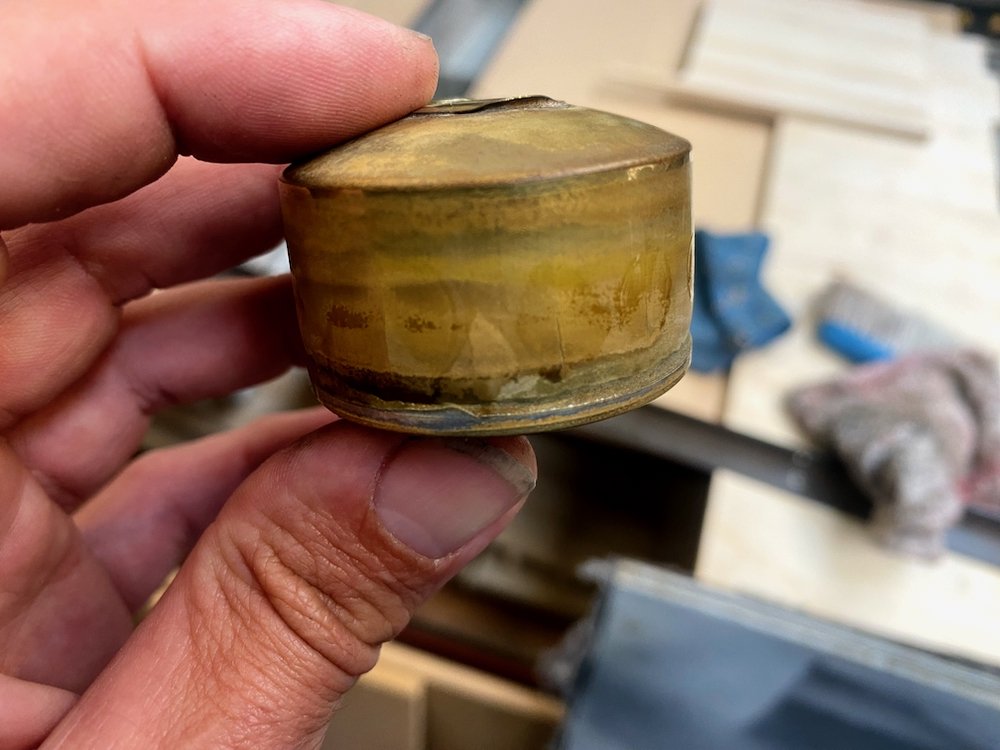
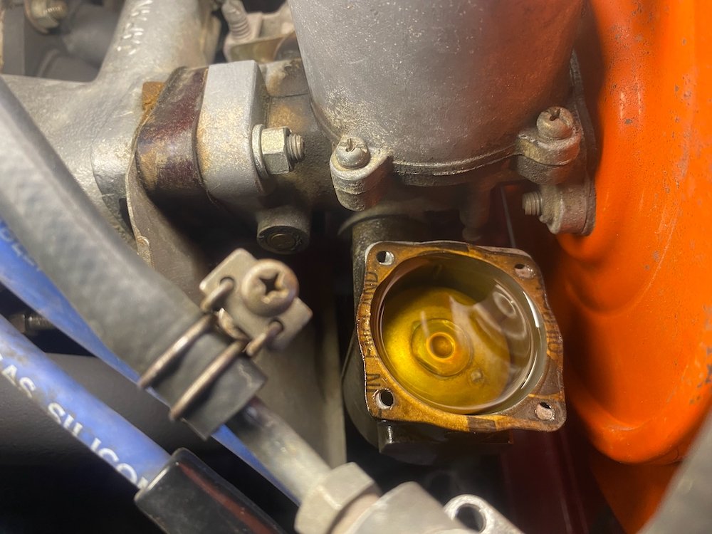
All running and driving, or so I thought Had a the plugs occasionally foul on start up and the engine now and then would start running super rough, running through the options didn't find much until after one drive I could definitely smell fuel, queue a case of the o shits etc. Leak was from the forward carb overflow, popping the lid off the float chamber was evident Seems we have a slight case of the oceangates.... Brass float had cracks all the way around. When I brought the car I also received a pretty good spares package so picked out the best looking float and threw it in. WOF man then failed the inspection on a number of minor issues, brake balance wasn't up to his expectation, small exhaust leak at a joint and rear brakes grabbing, managed to solve all in quick succession after work and sticker status returned! I haven't worked out the number of days but approx 3 years after taking the car off the road I can now legally drive again, while no where near finished in my mind, it is a giant relief to not have a pile of parts in the way! Still to go is interior re-trim, carpets, door seals, paint detailing, polishing, wheel refurb etc, mainly tidying up the cosmetics. But for now, lets go for a hoon around the neighbourhood
2 points
-
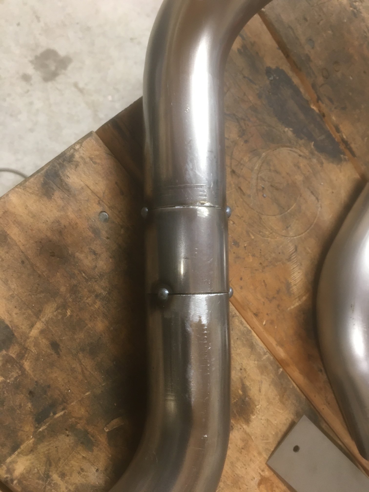
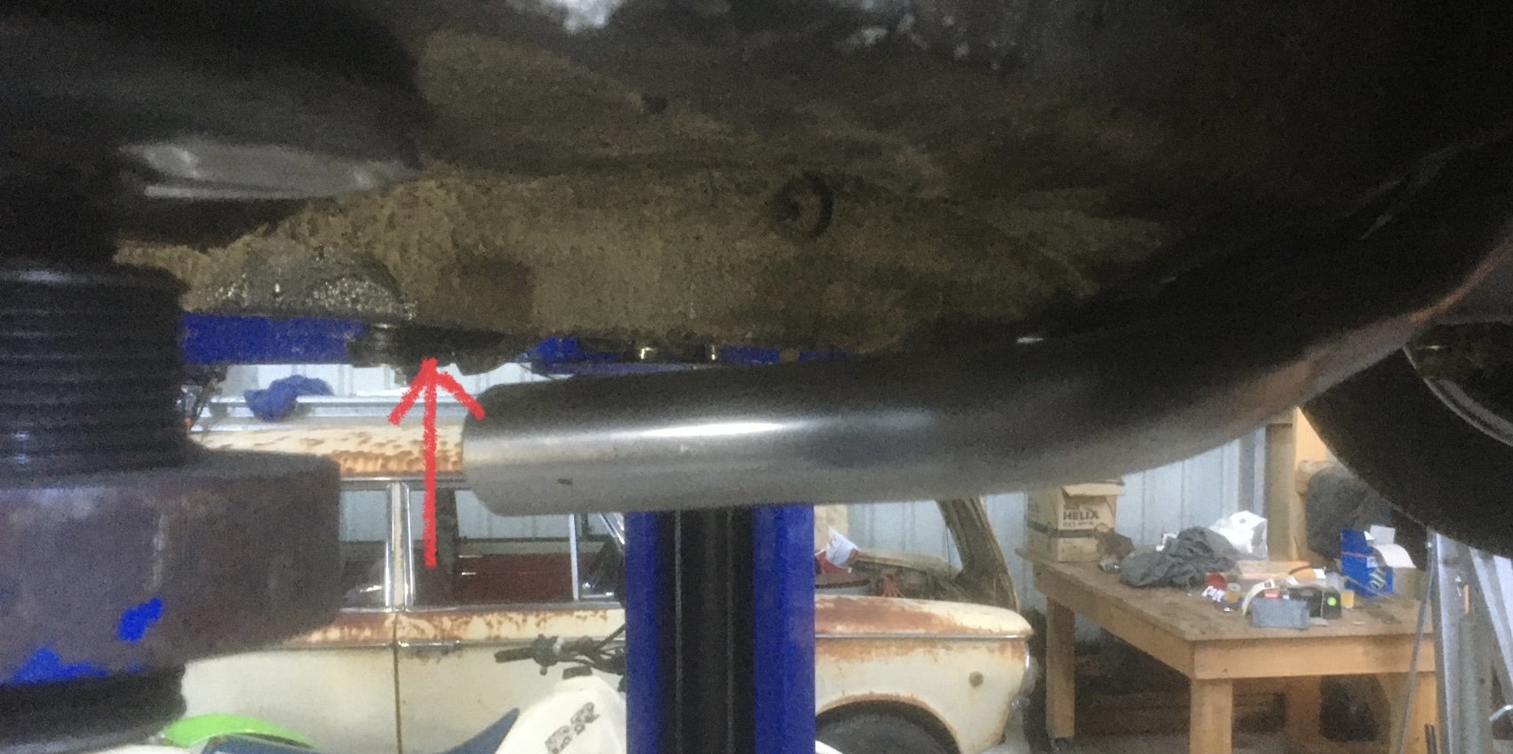
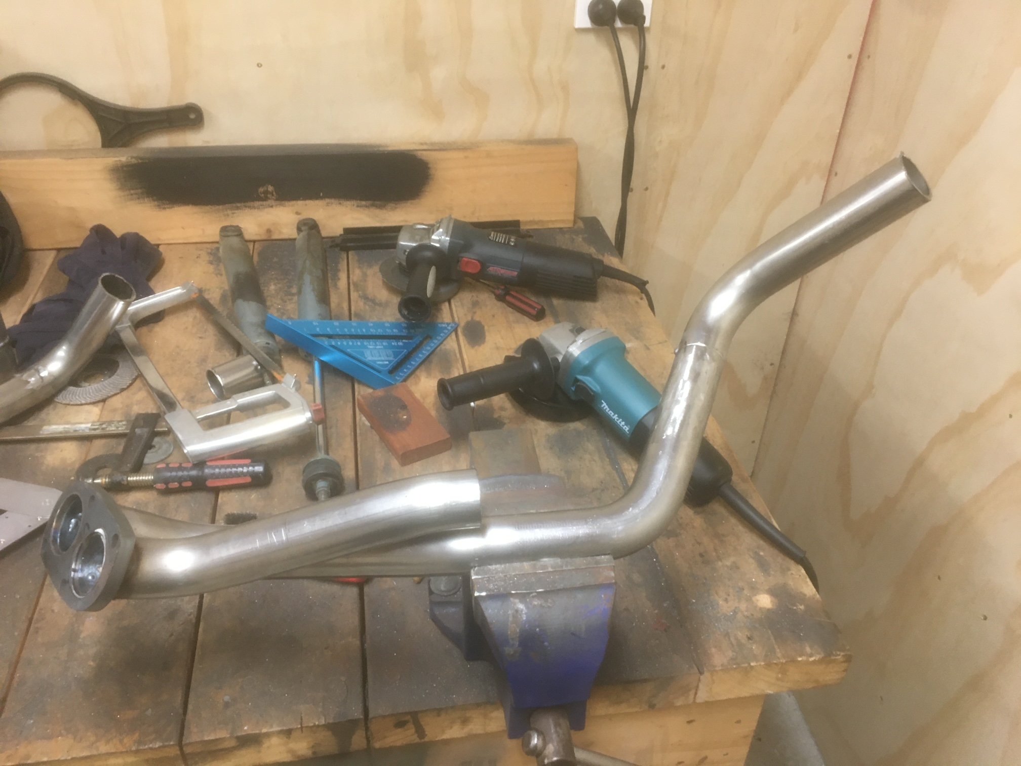
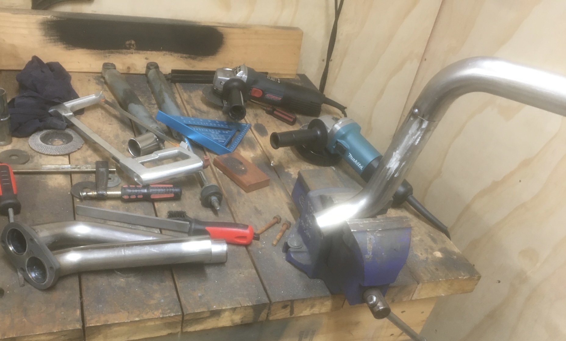
Part 2... catching up now. I finished what I needed to on the loom to enable testing of the injectors. I had made a simple little alloy jig that I could bolt the two rails onto and it sat high enough that 6 matching jam jars could sit below. We set this lot up on the big mobile steel bench and rolled it down to the front of the workshop near the entrance just in case it all goes a bit wrong. Set the ecu up along with a little 'ignition' switch and starter button for later testing of various engine sensors/ test running. The tuning software that megasquirt uses, Tunerstudio, has a good set of testing programs built in including injector testing. Started using that and as soon as the injectors primed and started squirting we found a tiny leak. Poos. My home made rails were brazed together and there was one teeny bit the bronze hadn't flowed into leaving a tiny pin hole that let out a comical jet of fuel. Glad I tested them now. Here under that lovely layer of carefully applied epoxy black... was a tiny hole.. So out with the oxycet and I brazed it up. Then re-tested the setup. No more leaks We ran through a few tests and made notes on fill rates at different opening times/frequencies etc etc to work out the injector dead times. Not a crucial thing to do but since it was setup as such it seemed rude not to. The battery I had was a bit tired and my charger couldn't keep up so I installed a larger wheeled type of Nissan charger at the front of the workshop. This also meant the testing was being done at a realistic voltage you'd expect to see. Happy the injectors were all matched and meeting the factory Nissan specs I packed all the stuff away. Then I fitted the inlet manifold gaskets and bolted the inlet in place on the engine, followed by the rails, with the repaired bit hand painted with epoxy as best I could to match. Next job to finish was the Bosch style idle air control valve. It had far too big in and out bosses so I machine up some stepdown parts to suit a more sensible sized tubing. I needed to mount it somewhere out of the way, safe and not on view because its not very pretty. I spotted a handy bracket on the bottom of the starter motor that has a threaded hole. Perfect! I made a little P clip to suit mounting the iacv. which bolts here.. Like so... I did some more plumbing to suit and after a few last little bits of wiring the engine was about complete. I fitted the pod filter I'd bought a while back directly onto the throttle body but it will actually end up remotely mounted in a cooler spot. I was just waiting on some posh ventilation hose to arrive. The Imp got a fresh wof and we took some pics of it when down at a local swimming spot near Motueka. It looked neat on the river stone so I took some pics.. Went hooning up a local valley to get wild plums.. Got home and snapped some pics of the engine next to car. The perspective makes the engine look huge... Next stage was to bolt the exhaust headers in place properly with the new gaskets and special nuts I'd bought. But before playing with exhausts always be aware of the potential dangers, as so carefully pointed out in the workshop manual !... Manifolds bolted up fine but a few of the nuts are awkward to get started as its tight on space around the header pipes. Next parts in the exhaust chain was the flexible joints. My welding was improved a bit by wearing some reading glasses. I guess I just have to accept that aging thing and embrace the power of +1.5 because now I could actually see what I was welding. Its still not instagram weld porn but it'll do for this project Bolted the cross member in place and with a bit of alloy I was able to check the heights to weld the next sections at. Unfortunately I must have fabricated the LH manifold out of line and I have ended up having to weld the secondary pipe at an angle to make sure the outlet heights match. It wont be easy to spot when its on the car, with a exhaust box hiding them. But I know its there... Or maybe I don't bother with a single large tranversely mounted silencer and just run a couple of old dumpy mufflers... I was now at the point I could fill the engine with oil and test the oil system. Quite a while back I bought some quality oil when on sale.. I filled the filter up first and then carefully filled the engine. Up until this point I had no real idea of exactly how much my resized sump would take before it got to height I wanted it at. I'd done some basic sketches and napkin formula and I knew it would be more than 3 litres. Hopefully more than 4. It almost took 5 litres to get to the halfway point on the sight glass and that will drop once the oil pump primed up and filled the oilways. Cool. Great news then. I'm really happy it'll have a decent amount of oil in there. Now remember back to around the end of December 2021 when I wrote this... "Lastly I needed to bolt the sump cover in place. I had to think carefully about bolt placement for sealing purposes and get the bolts square. This sump plate is going to have to be sealed well because there is no usual high sided sump like most cars. Hence I built it rigid to help against flex. Good quality sealant will be the order of the day* *It will leak. Its a British car. Its destined to leak." Well then. Guess what. It leaked! Ha. Just after patting myself on the back at having a great sump capacity the level started to drop and was leaving a good puddle on the engine stand top. So Hannah helped me move the engine so I could drain the sump and then I mounted the engine/box assembly into the spare imp. On a positive note I was chuffed with how quick and easy it was to bolt up in place by myself - all of about 5 or 10 minutes. Engine in place and with the car up in the air I took that above photo. I had a good idea where it was coming from and wasn't feeling to glum (not even a single toy was lifted from my cot) I unbolted the sump plate and found the hole... Back when I was machining the sump plate and milling the slots it wasn't initially clamped down tight enough and it shifted out of line without me spotting it. By the time I noticed it had moved it was too late. I had to weld up the resulting mess and re-machine that area. I thought it was all fine but I'd obviously missed a tiny pinhole, maybe exposed when I machined the inside of the plate out to take some weight off it. The plate got a good clean (that threebond sealant is tenacious stuff! ) and I fixed the hole with a dollop of JB weld. Took some pics of engine from below with its innards exposed.. Little pistons... Bolted the sump plate back up, waited till the following day and refilled it. This time no puddles. Yay. While the engine was bolted into the spare imp I took the chance to double check measurements and clearances. It was all looking good and I was very happy that I had placed things ideally, especially as most measurements were taken in awkward areas by all sorts of various ruler/tape measure/level balancing acts. The ignition coils for example, just mounted on their makeshift bracket I'd made for bench testing, are actually almost bang on in the right place and only sitting a touch too high. The filter hose will just clear the underside of the parcel shelf and there's heaps of room for the remote filter.. Hose (turned up the day before) .. Hannah's hand holding filter roughly where it will be mounted to the bulkhead... Lots of room out back between engine and where the removable rear valance bolts in place.. and lastly, the 'Mandalorian spaceship' will not at all be hidden by the rear parcel shelf .. Engine is now out and back on the bench for more 'bench testing'...2 points
-
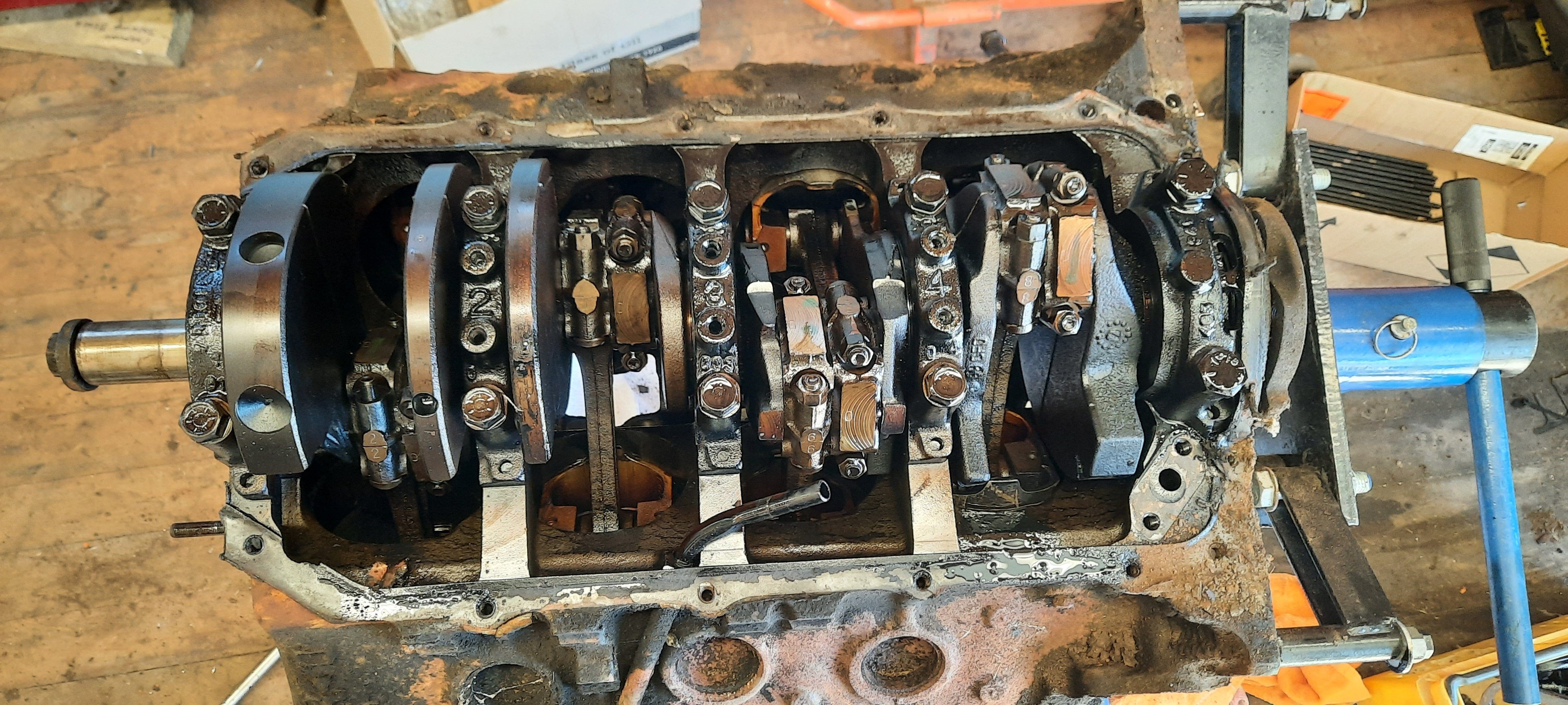
Stripped the rest of the motor down. Crank has been hammering a bit so will be crack testing that and the rods. Otherwise it looks like .030 in the bores ans .010 on the journals will sort it out.
1 point
-
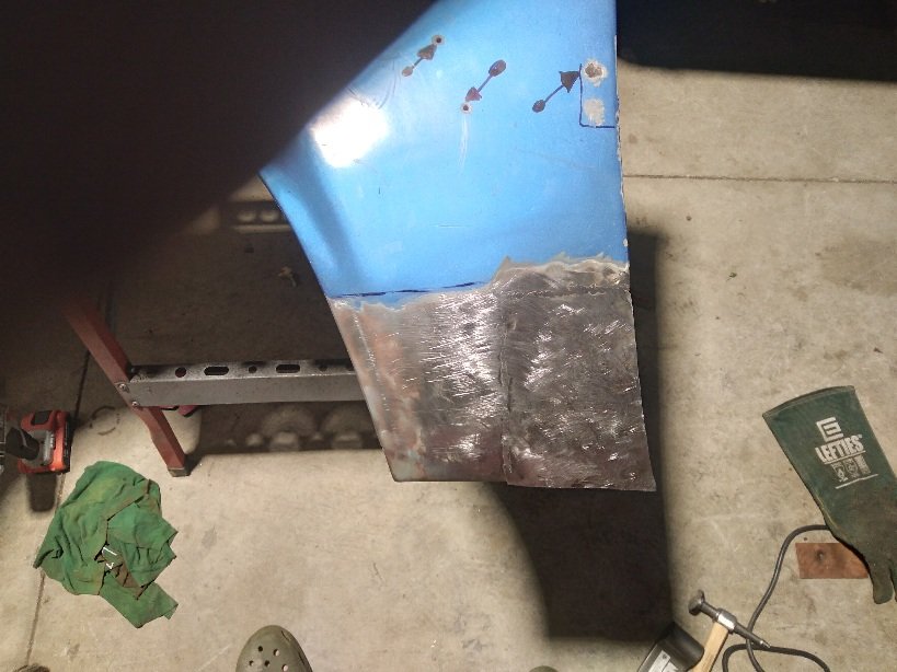
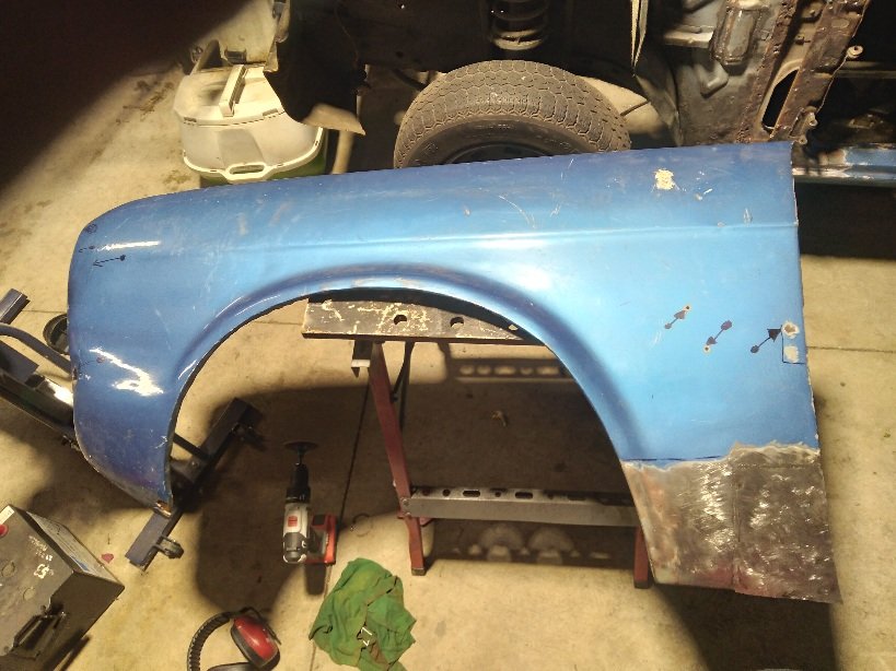
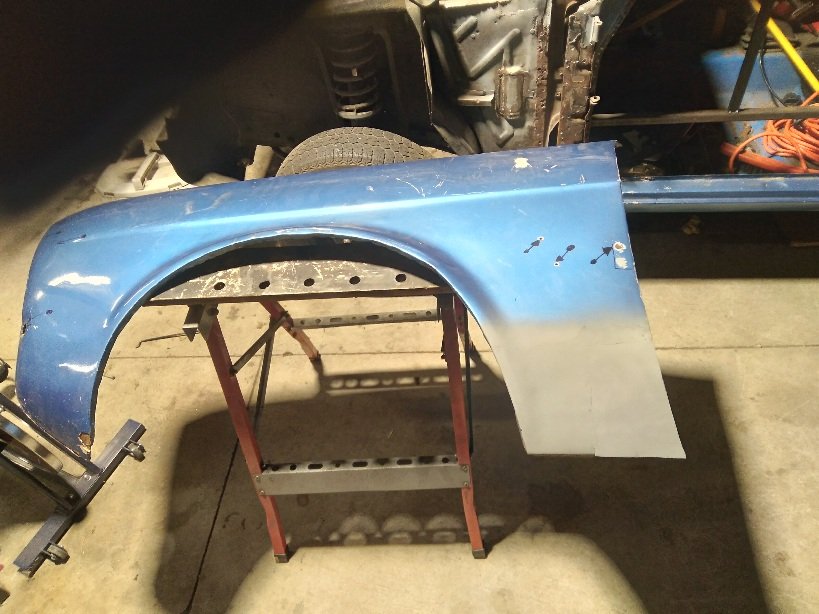
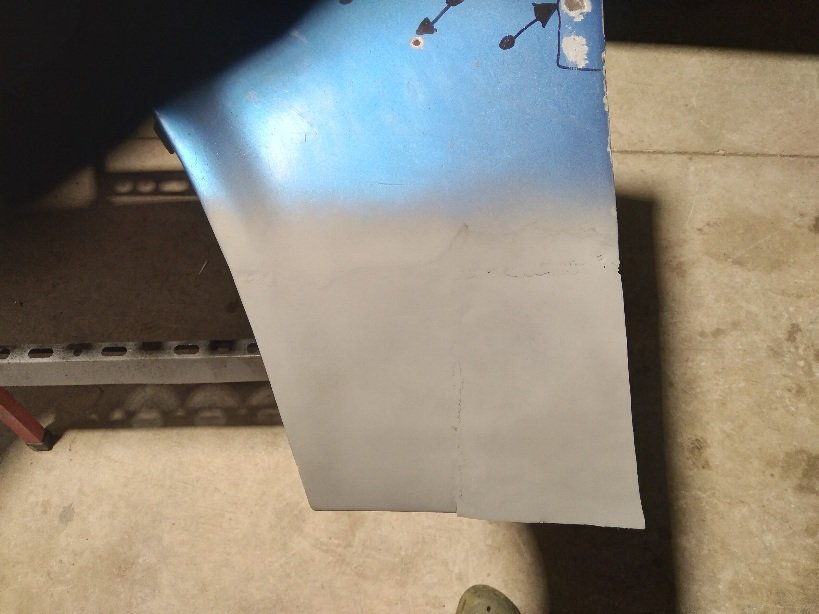
Well tonight I decided to weld the patch panel in Not sure if I'm happy with it but will sleep on it. Still have to finish the bottom of the patch and also make an inside flange for the wing Fitch panel to fit into. I also took to it with a dolly and a panel hammer to try and sort out the low spots. Might give it a weld from the inside to get ultimate penetration.
1 point
-
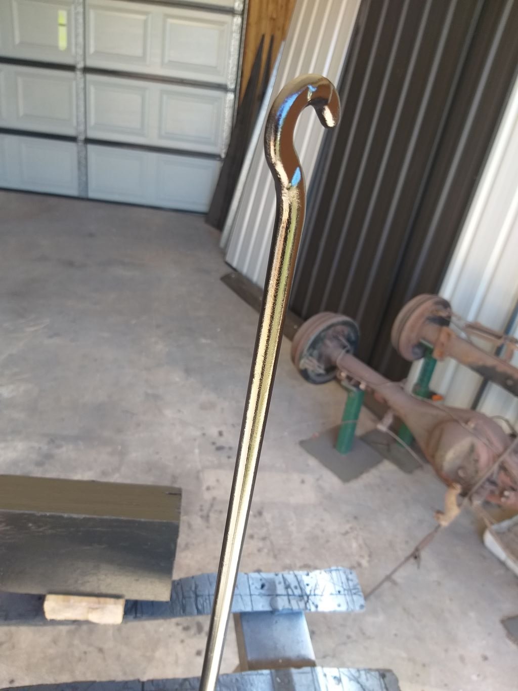
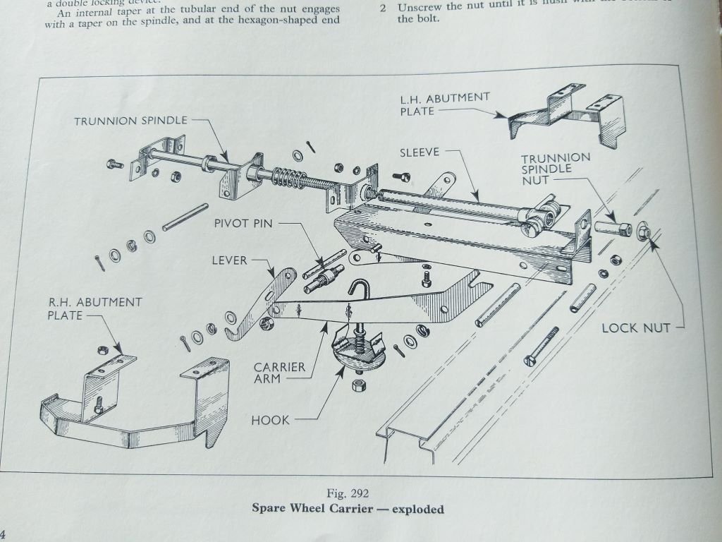
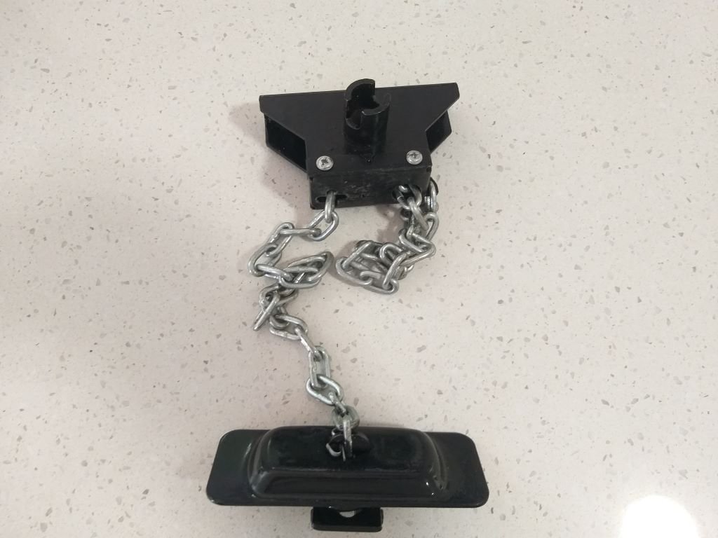
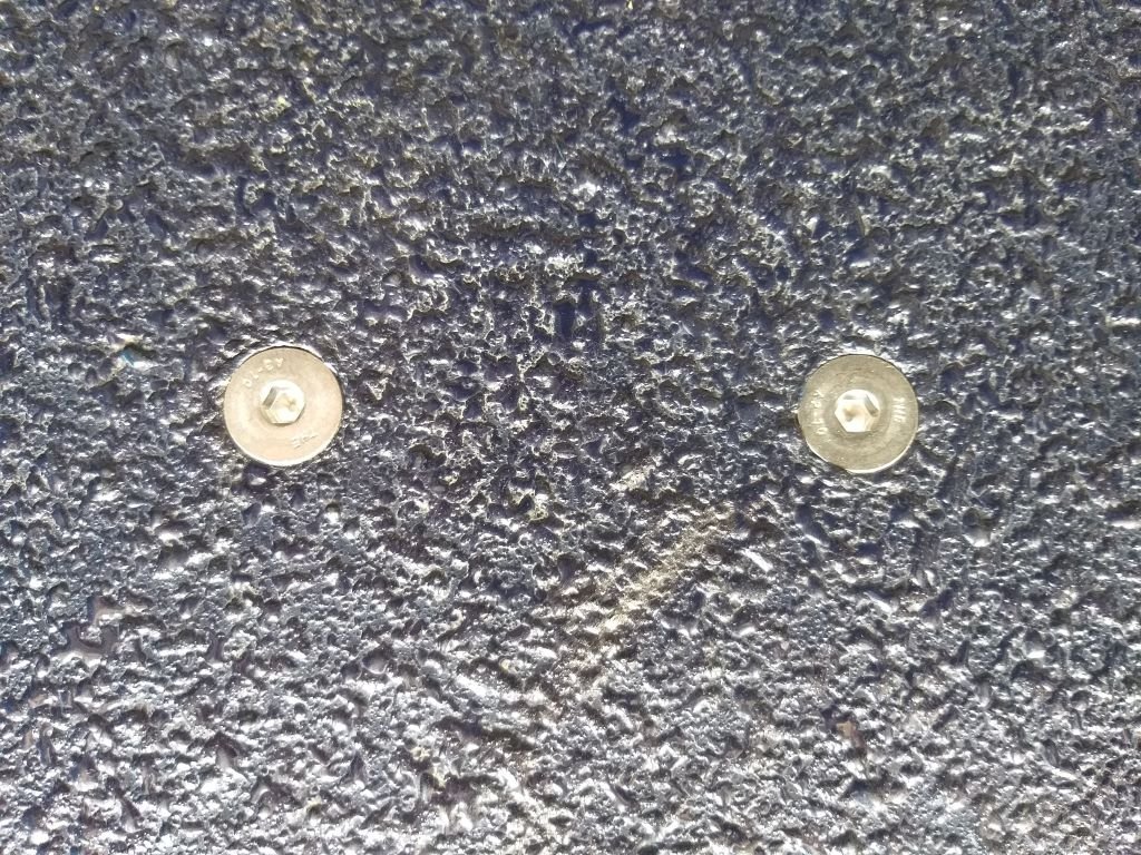
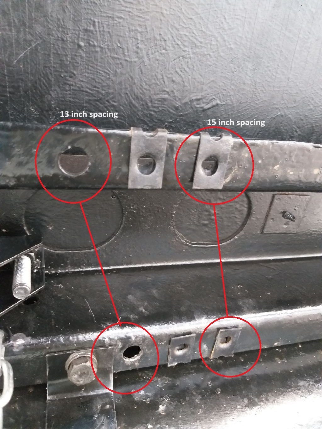
Well according to the Captain's Log it's day 656 on the Thames build and I thought I'd celebrate the fact by adding a spare wheel. When we bought the van it had no spare, but the factory wheel carrier and lifting mechanism was still in situ. The original mechanism was pretty complex, so I suspect that the Dagenham based propellor head responsible for the design was on an hourly rate and decided that it was time to milk the system for everything it was worth. Schematic of the system looks like so: Unfortunately, the threaded rod, ... ahem ... I mean the trunnion spindle, was seized solid and no amount of lubrication would free it up, so I ended up taking to said spindle with my grinder of angles way back when I refurbished the underside, and the van has been going commando ever since. So as part of my Christmas present, Santa popped one of these fine marvels of modern engineering into my stocking: And as previously mentioned today was the day to figure out how I was going to mount the thing. So I grabbed the bull by the balls and headed under the arse end of the van for a look see. Turns out there is a perfectly placed chassis cross brace that looked like it might do the trick. The first part of the exercise was to try and make the new mechanism line up so that the crank handle hole in the rear Thames badge would still work. So, I started off by poking an appropriately sized steel rod through the hole in the badge and then through the corresponding hole in the chassis cross brace. The rod was able to temporarily hold the new lifting mechanism in place. Next step was to prop the spare wheel up on a few blocks of wood and then drop the lifting chain to make sure that it lined up with the centre of the spare wheel. As luck would have it things lined up perfectly, so it looked like I was off to a good start. Slapped some white paint on a spare bolt and poked it through the threaded nuts attached to the mechanism and I now had a good guide for the mounting holes: The flooring in the load area is still the original ply that was rubber lined by the previous owner, so I figured the easiest thing to do was to lift out my false chequer tiled floor and then drill some pilot holes through the chassis cross brace and then up through the ply. Eventually ended up with the correct diameter holes and bolted the mechanism up. Worked perfectly and I ended up with these countersunk beauties: Next step was to attach the spare and winch it up into position. These vans were offered from factory with two wheel options, option 1 being 13-inch diameter and option 2 being 15-inch. Again, the forward-thinking engineers had allowed for both options when it comes to the spacing of the abutment plates which is achieved by moving the captive nut thingies to the appropriate holes: Unfortunately, my spare is a 14-inch wheel so I had to mix and match the spacings to get the wheel to sit snuggly, but it's all good now. Tomorrow exercise is to turn these little bits of scrap into a crank handle for the mechanism: Thanks for looking.
1 point
-
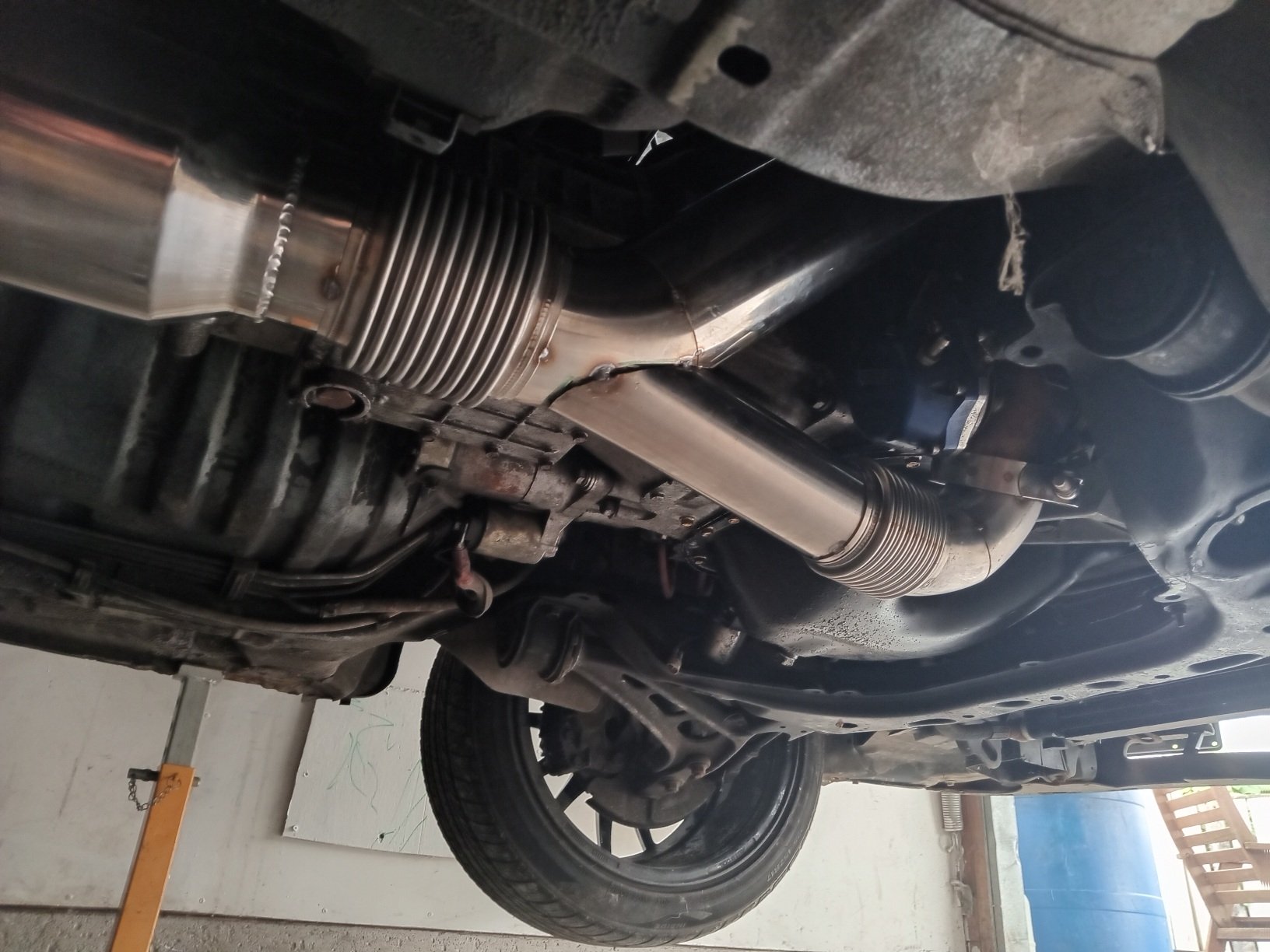
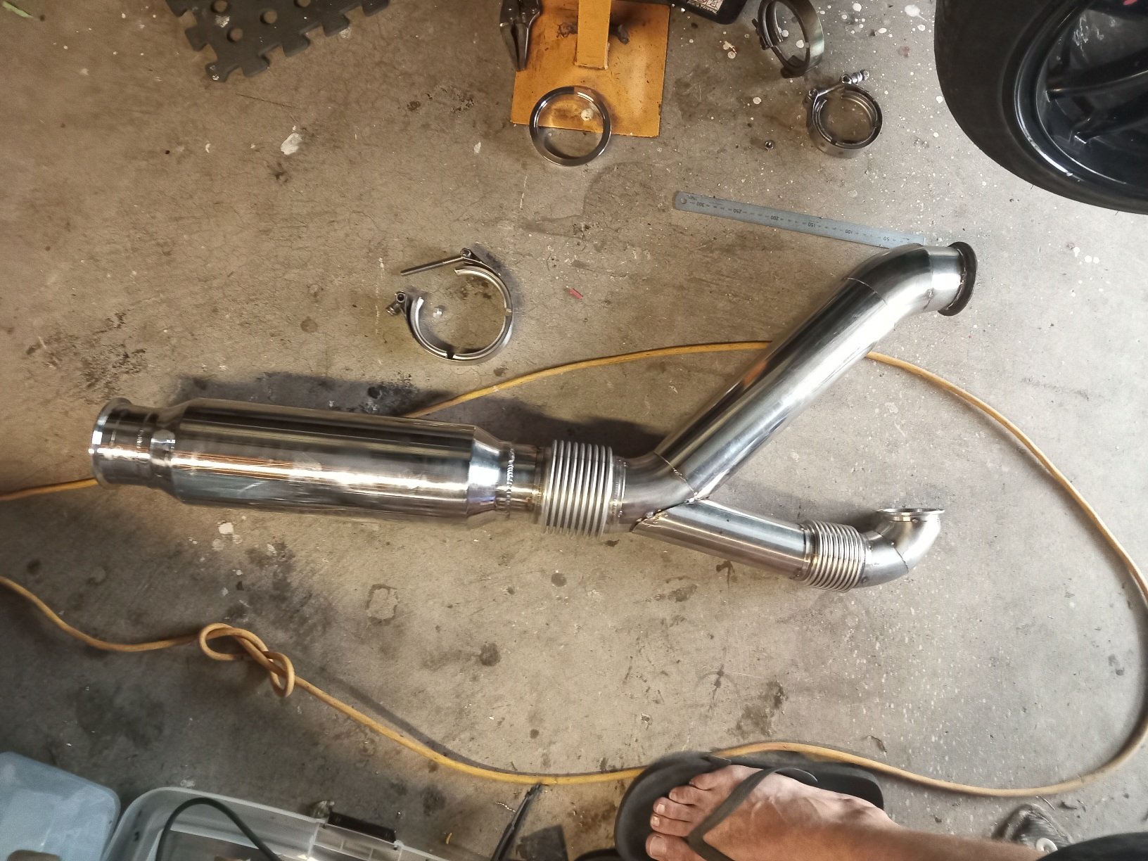
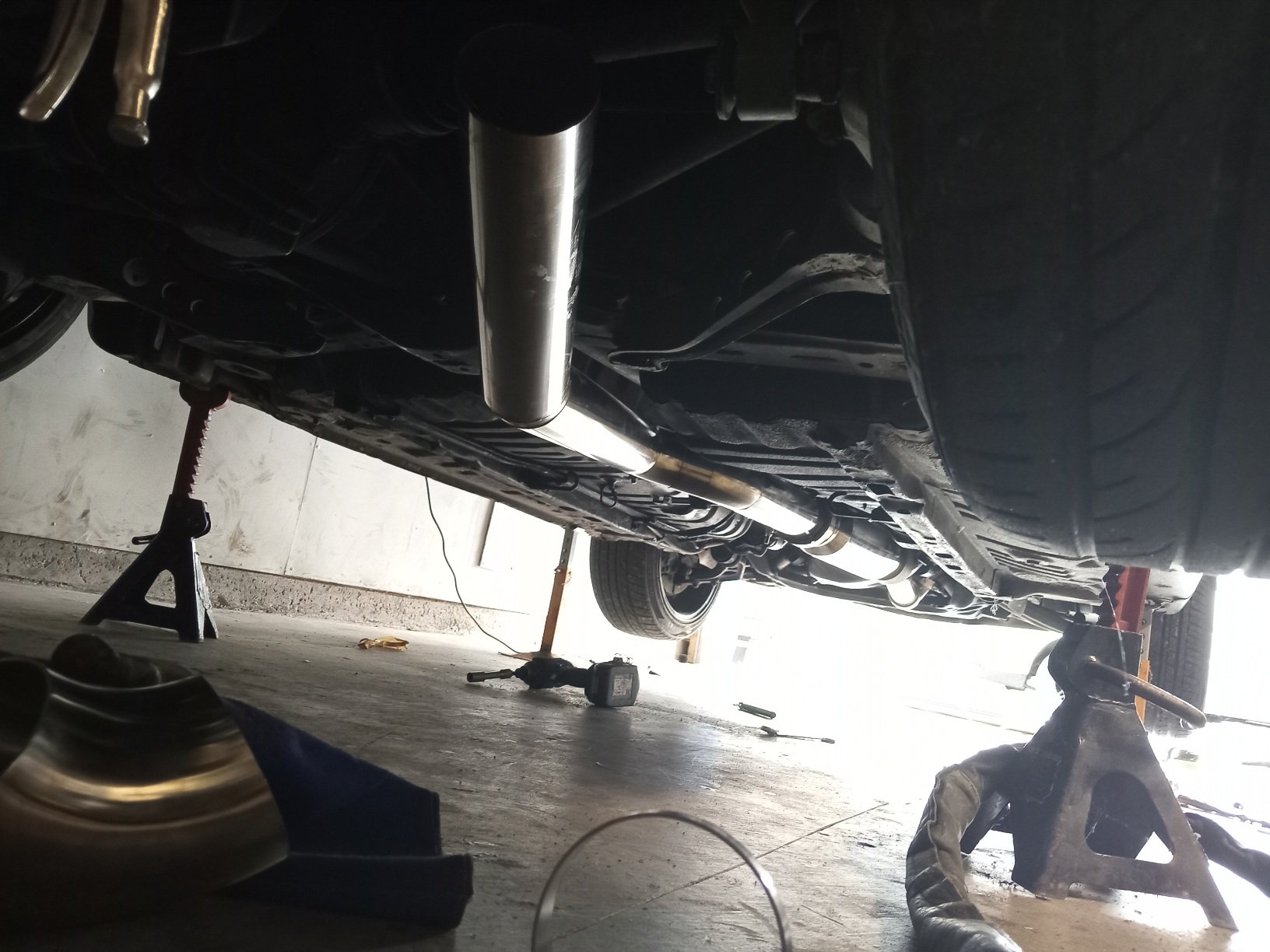
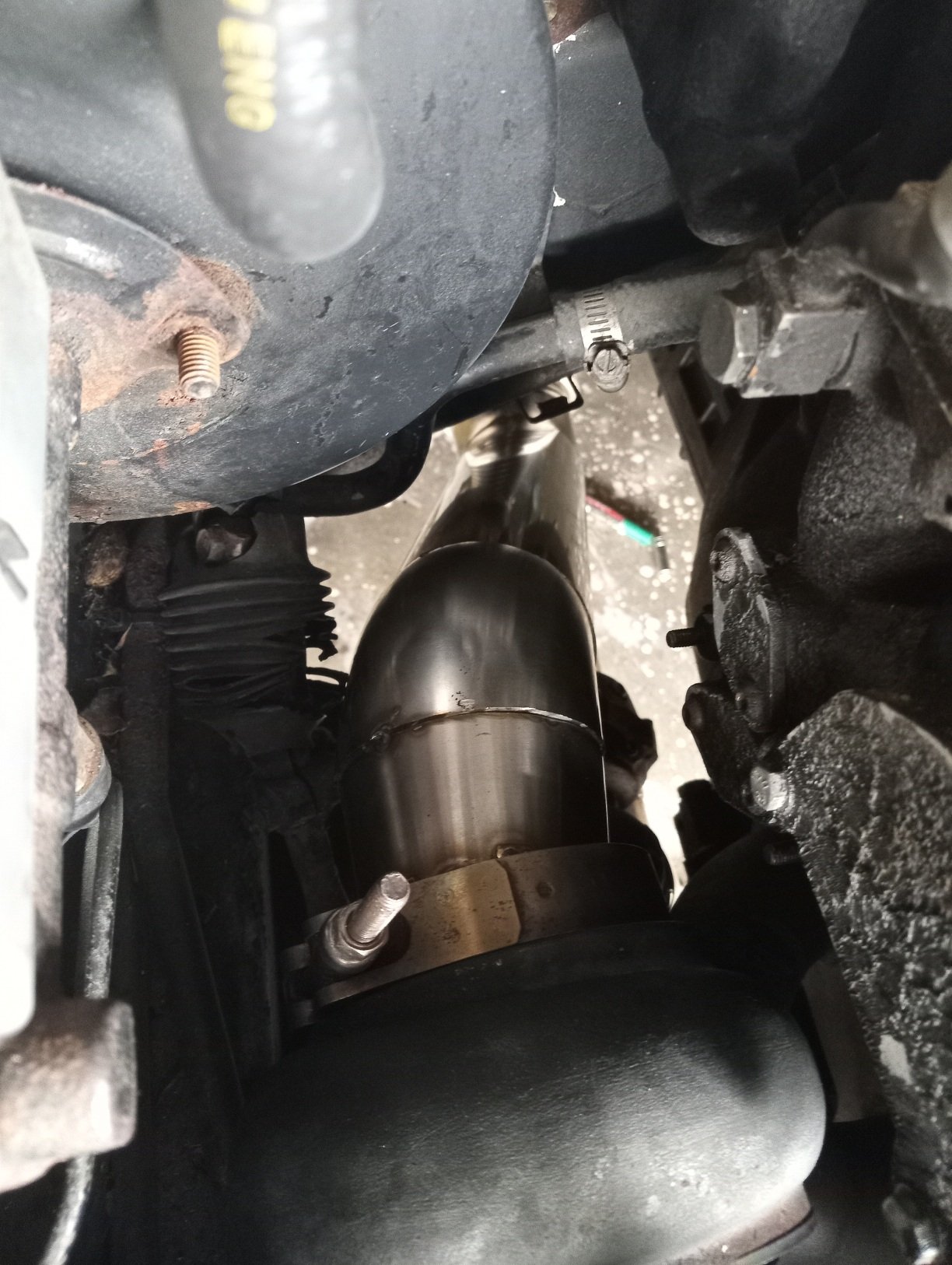
Spent today welding up the 3.5 inch exhaust, got to the diff end, will have to finish muffler up and full weld in couple days, maxfab kit is pretty good quality for 800 or so $ for everything inc resonator vbands, shipping etc. Trying to keep it all flush to bottom of car, the diff area is only place it has to dip down a bit but im happy with it ..
1 point
-
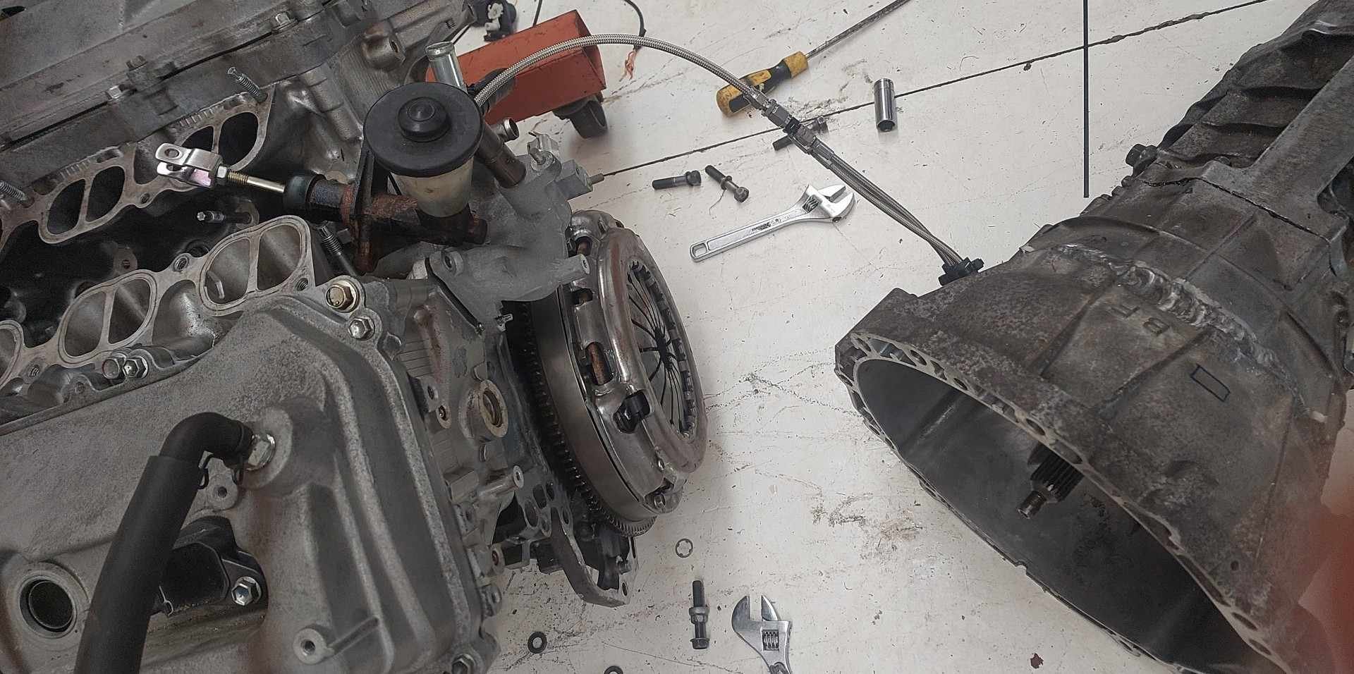
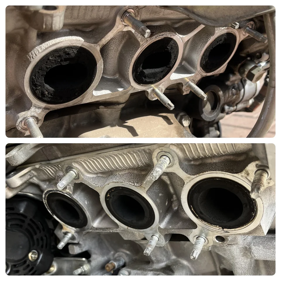
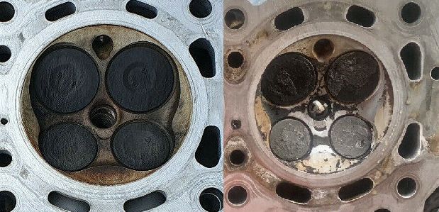
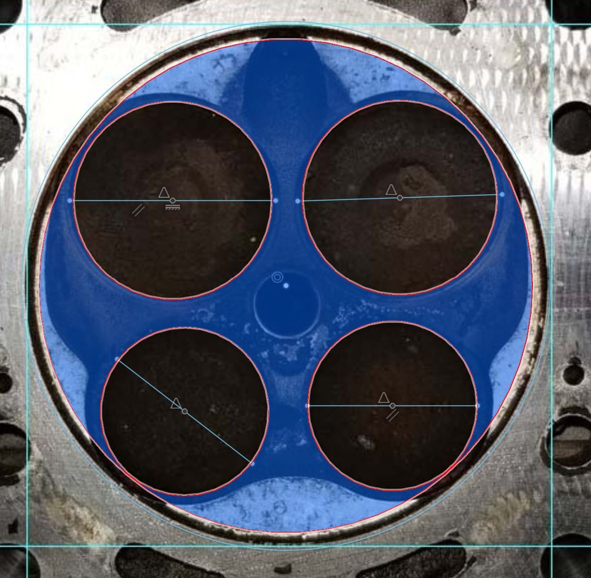
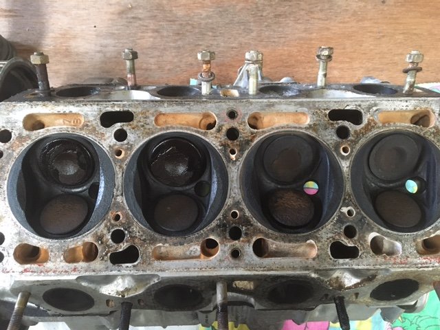
I put my timing cover back on, and then tried to crank over the motor while it's in gear with all of the drivetrain connected. So I can find the clutch point to put a stopper when the wheels stop turning. Overextending the concentric slave can mean it dumps its guts into your bellhousing. Do not want. I try turn over the motor - clunk. nothing. damnit what. I try cranking the motor via the front pulley, and it just goes super tight. hmm. Soooo I put the engine in neutral, and try turning the rear wheels. Thats fine. no noises. So I pull the motor and box back out, thinking there must be something jamming to do with the release bearing or clutch as that's all that's changed. Or maybe the lines were dragging on the cover plate or something. However, no obvious signs of issues. Just to eliminate it as a possibility I removed the starter motor - then sure enough the problem stops. Put it back in, then its a problem again. Which is very weird, considering it's worked fine literally just days before. So it looks as though the starter pinion thing either isnt going as far back into the housing as it used to, or... fuck knows. If I put some washers on the starter motor bolts to space it back slightly, then everythings fine again. But I'd prefer not to be point loading it when it's otherwise supported by the full housing. Damnit. It's only by the smallest amount, maybe 1mm. I'm tempted to just dremel back the pinion in the starter slightly. The clutch and release bearing all seemed fine though, which was good. Here's a trick for avoiding needing to bleed a concentric clutch when you pull a motor out - Just bring the MC along for the ride haha. Alsoooooooo something else interesting that I've just discovered. My understanding was that the 3GR and 4GR heads were the same. However I just stumbled across this pic. The top picture is the disgracefully weeny 4GR exhaust ports. Second pic down is the 3GR exhaust ports. Much bigger exhaust ports on the 3GR, and circular. Interesting. So finding some more pics, looks like the 3GR has bigger valves too. Look at the difference in the amount of space between the exhaust valves in particular. (3GR on the left, 4GR on the right) Checking on Toyodiy.com and it confirms that the 3GR has different part numbers for valves on both sides. The 4GR has a slightly smaller bore size (83mm vs 87.5mm) This pic below is how a 3GR head would fit onto a 4GR bore size. So the valves would fit without conking the bore. Based on my dubious scaling the valves are approx 33mm on intake side, 28mm exhaust side. Compared to from memory 31mm intake side, 25mm exhaust side. It would be interesting to see if the intake side geometry/port sizes are any different as well. I'm broke as shit currently, but if I see any more 3GRs come up at pickapart I'll go pull a head off and measure it up. Then I can decided if it's worth putting 3GR heads on. I'm sure as hell not looking forward to cleaning all of the shit out and porting some more heads though. What a mess! For the meantime though just carrying on down the critical path items towards getting the motor running. EDIT: There's a whole 3GR engine on Trademe for 300 bucks. Ha! Would buy if it was more local, and a few more months down the track. God bless these shitty unloved engines. https://www.trademe.co.nz/a/motors/car-parts-accessories/toyota/engines/listing/4519312323
1 point
-
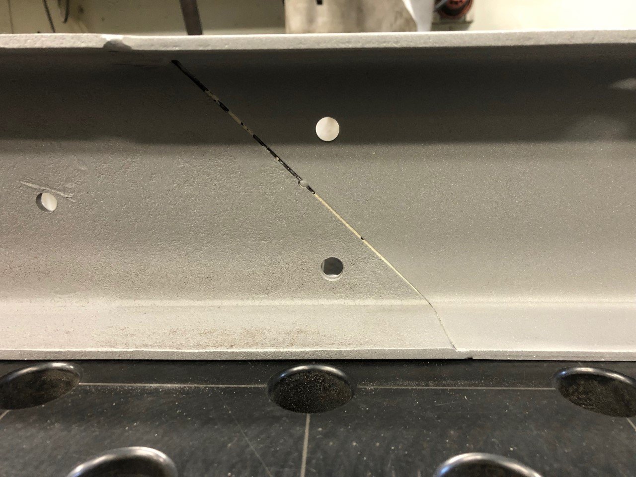
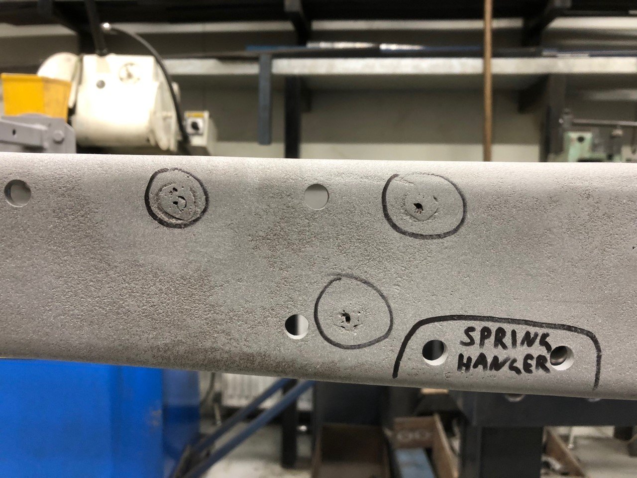
Progress: The chassis-rails were full of holes drilled in incorrect or non-parallel positions. These have been welded-up. There had been addition inserted into the longerons of about 415mm, which corresponds to the difference between a Type 40 chassis length and that of a T44 or (short) T49. We found poorly-welded-over holes that would have exactly corresponded to the positions of Type 40 engine mounting bolts, so it appears highly likely that my chassis started life under a Type 40, painted a red-oxide colour. The chassis inserts were made from non-matching steel profiles, of incorrect thickness, and had been welded only across their upper & lower webs, then bogged-up and painted over. They were fundamentally cosmetic and would not have performed a structural role beyond the first serious pot-hole. These have been removed, and replaced by correctly dimensioned and properly welded inserts. Horribly wrong chassis insert hidden beneath the paint & bog. Since removed and replaced properly. Texta markings show original holes for engine-mounting bolts, matching with dimensions for a Type 40 Bugatti - a friend with a T40 sent me photos and a template to double-check!
1 point
-
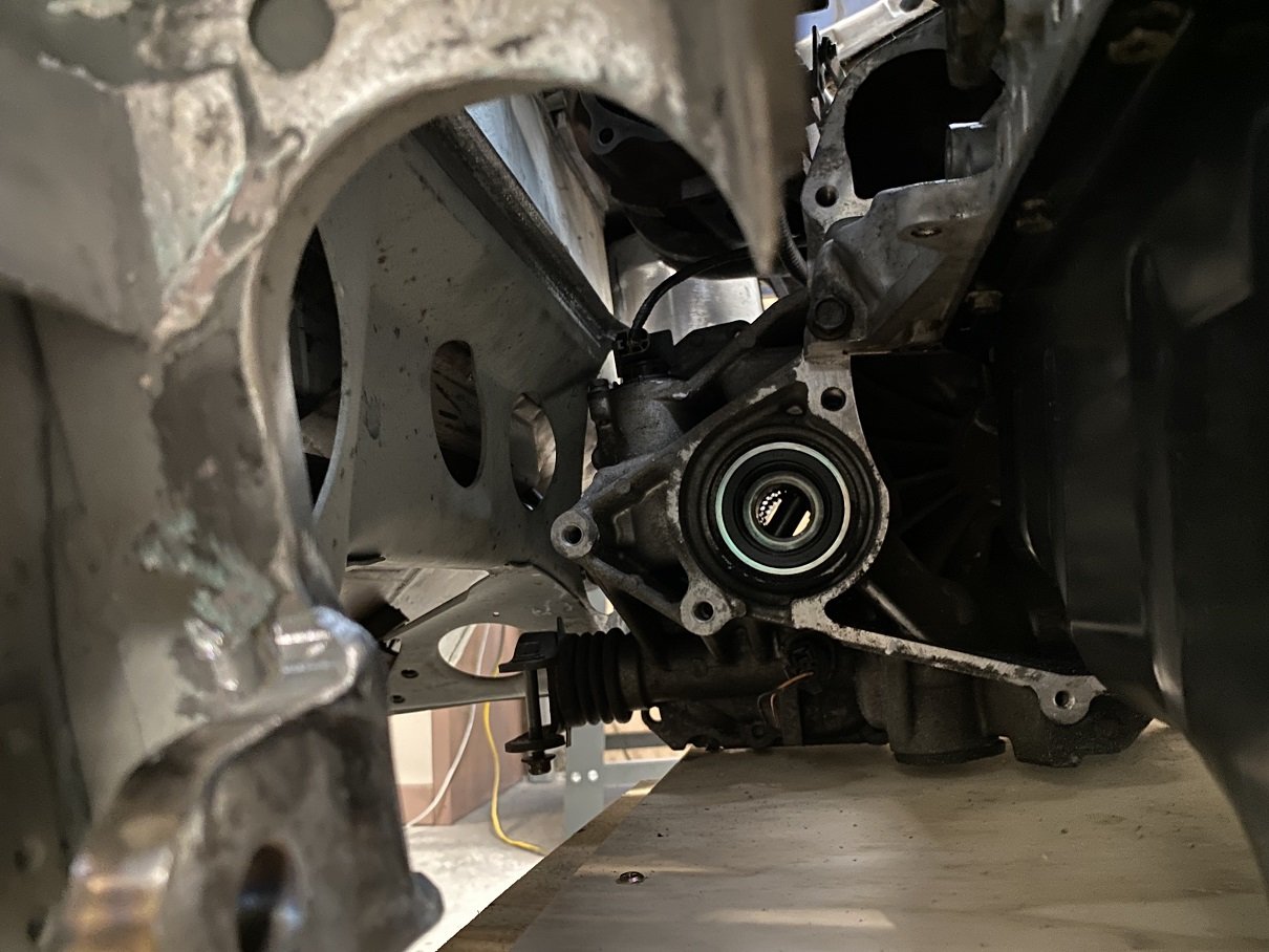
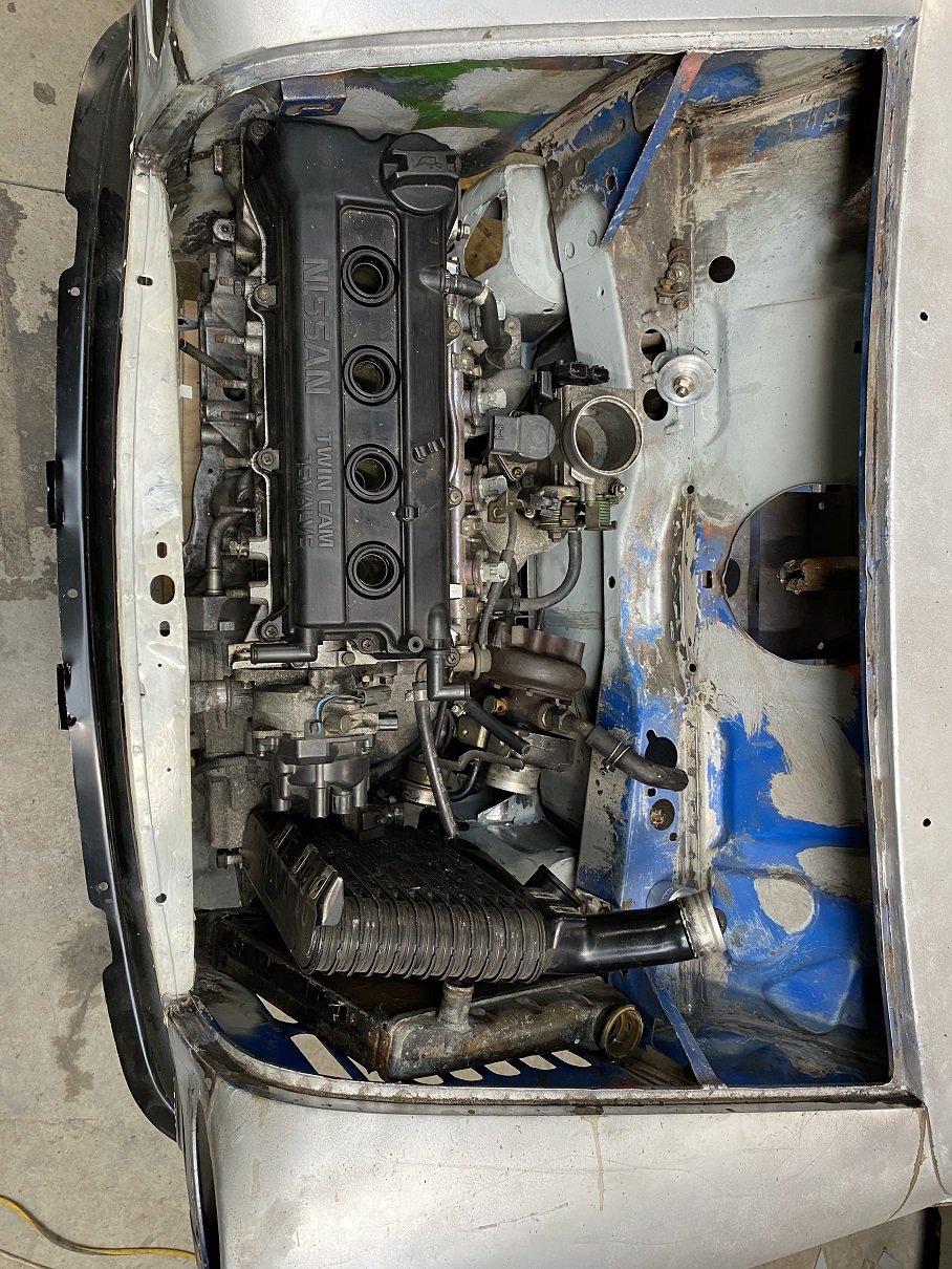
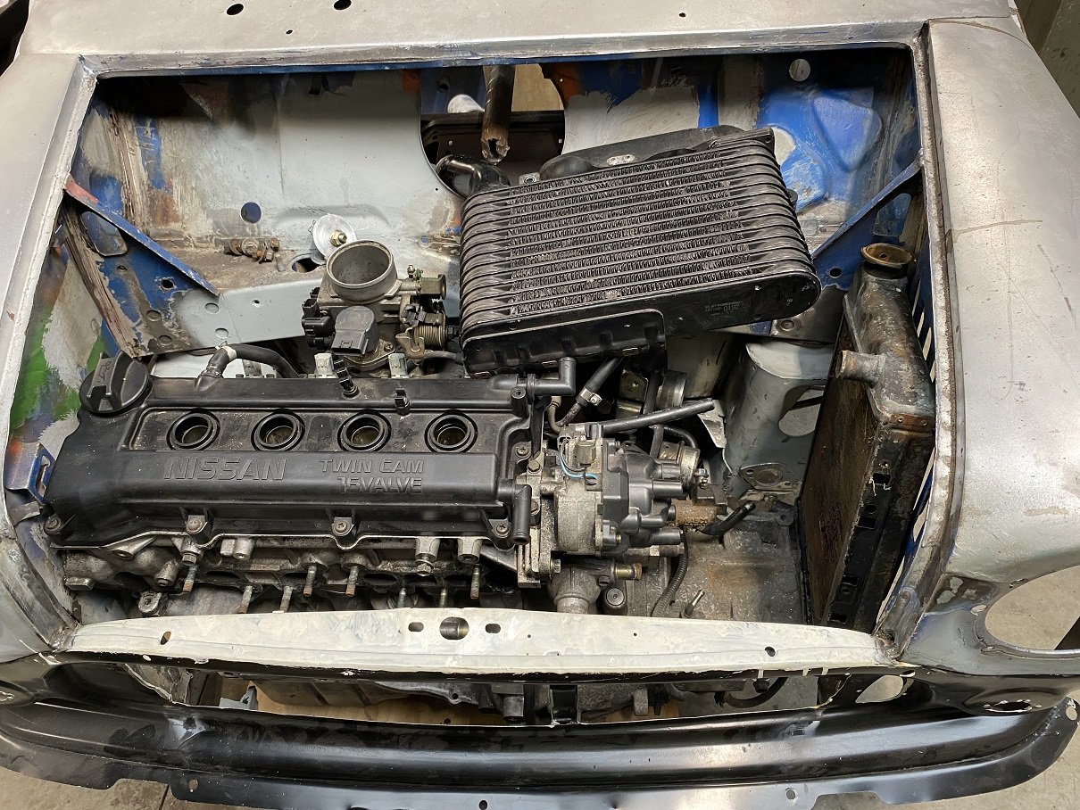
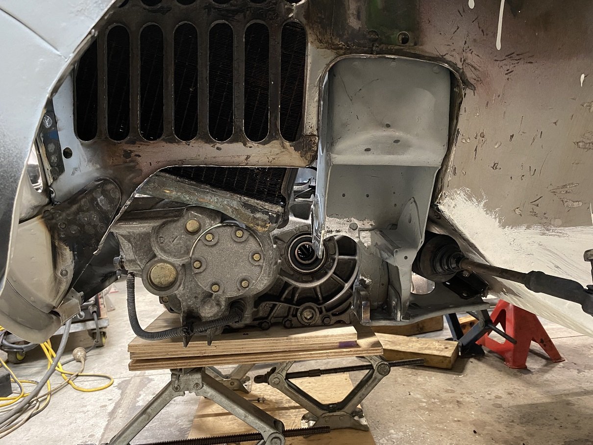
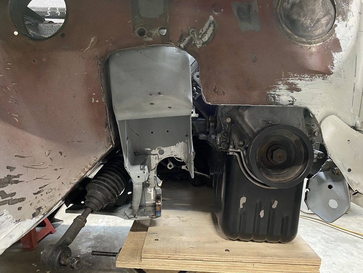
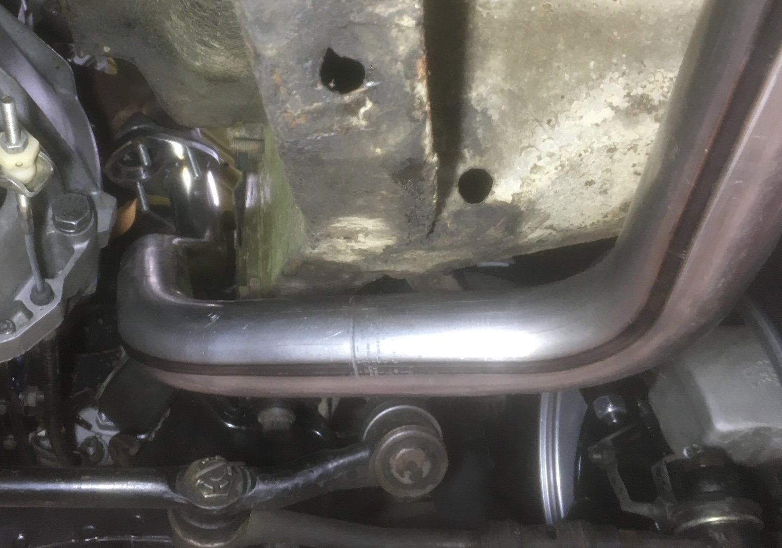
The engine is pretty much in the only place it fits. With more trimming around the back of the subframe I might get another 10mm before the gearbox meets the steering rack. I'm going to step the top/front corner of the inner wing into the guard to get a little more clearance off the corner of the head. I threw some "stunt parts" in the hole to see if there is any chance this is going to work. Mounting the turbo at the front will have almost all of it in front of the grill.... But if I put it over the gearbox... There might be enough room to run the manifold under the engine, then up the back to the turbo then back down for the dump pipe. Loads of room if I top mount the IC.... interwarmer styles. Gonna need a powerful fan and vents... Only done the lower control arm mounts so far. Still got to make a bridge under the top arm mount. I trimmed the inner guards and hammered some new flanges to put some stiffness back in them. Turned out quite good! There will be a CV and driveshaft here to try get an up and down pipe around.
1 point
-
Thread dredge... For the last 18months or so this has been flat packed ontop of a container at work as it wasn't really needed with the aquiring the caravan. But with the caravan being out of action for repairs and the holiday break looming I dragged it all down and put the trailer back together. I timed it and it took me 25mins to setup which is pretty sweet. Unfortunately its got some overspray on it from some painting that went on, but overall its still in pretty good condition. As mentioned above I wanted to put something on the front to hold the water tanks and wash down pump etc. As luck would have it many years previously I had made a simple aluminium box from some left over treadplate that I was using as storage so that got repurposed and fitted to the front. I didnt want to drill into the draw bar so made up a clamp system from bits of ali off the offcuts rack at work. Its not flash, but it works and 2x 20litre tanks fit perfectly with the pump and room to spare. I cut and folded a piece of ACM to cover the draw bar which acts as a bench for doing the dishes etc. I also swapped in a Victron solar controller in place of the Powertech one which was inefficient by comparison. We had a great trip away with it - it tows well and it makes life super easy at camp grounds plus having the nicety of the fridge & freezer and light etc. Will probably leave it together for a while then flat pack it again late summer as I will need the trailer for collecting building supplies for some house projects this year.1 point
-
Merry new year. So…. No, I can’t rescue it. I started with this bit which became this which fit here which meant I had to lengthen the inner pipe so far so good. Side profile, the end needs more up: So I gave it a tweak which then meant the inside pipe did’nt fit and no amount of faffing about could get the angles right and I ran out of both bends and patience. I then cut it up and threw it in the scrap bin and ordered a new one from Britannia. About the same price as bending the new one and laser cut flange. Shipping hurt a bit though and I’m sure being a mass produced aftermarket part it won’t be quite as nice but I’ll find out soon. Meanwhile I managed to cobble the old exhaust back together without leaks and went for a hoon.
1 point
-
2013 vs 2023. Only got 42,000 km on it so far, but its been around nth island a bit
1 point
-
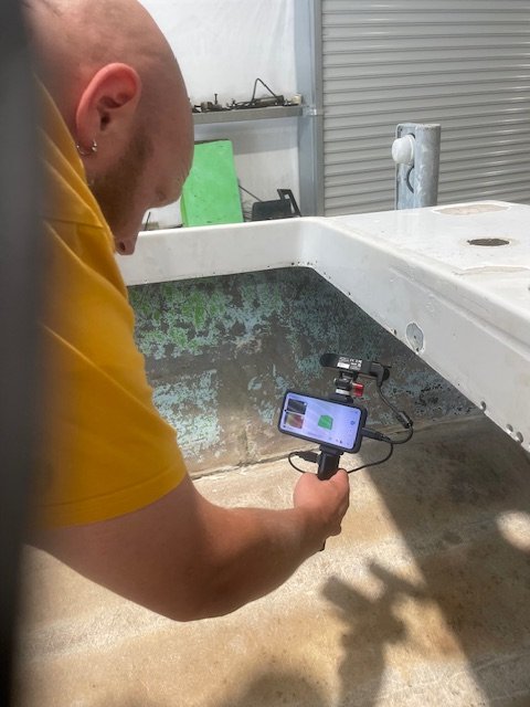
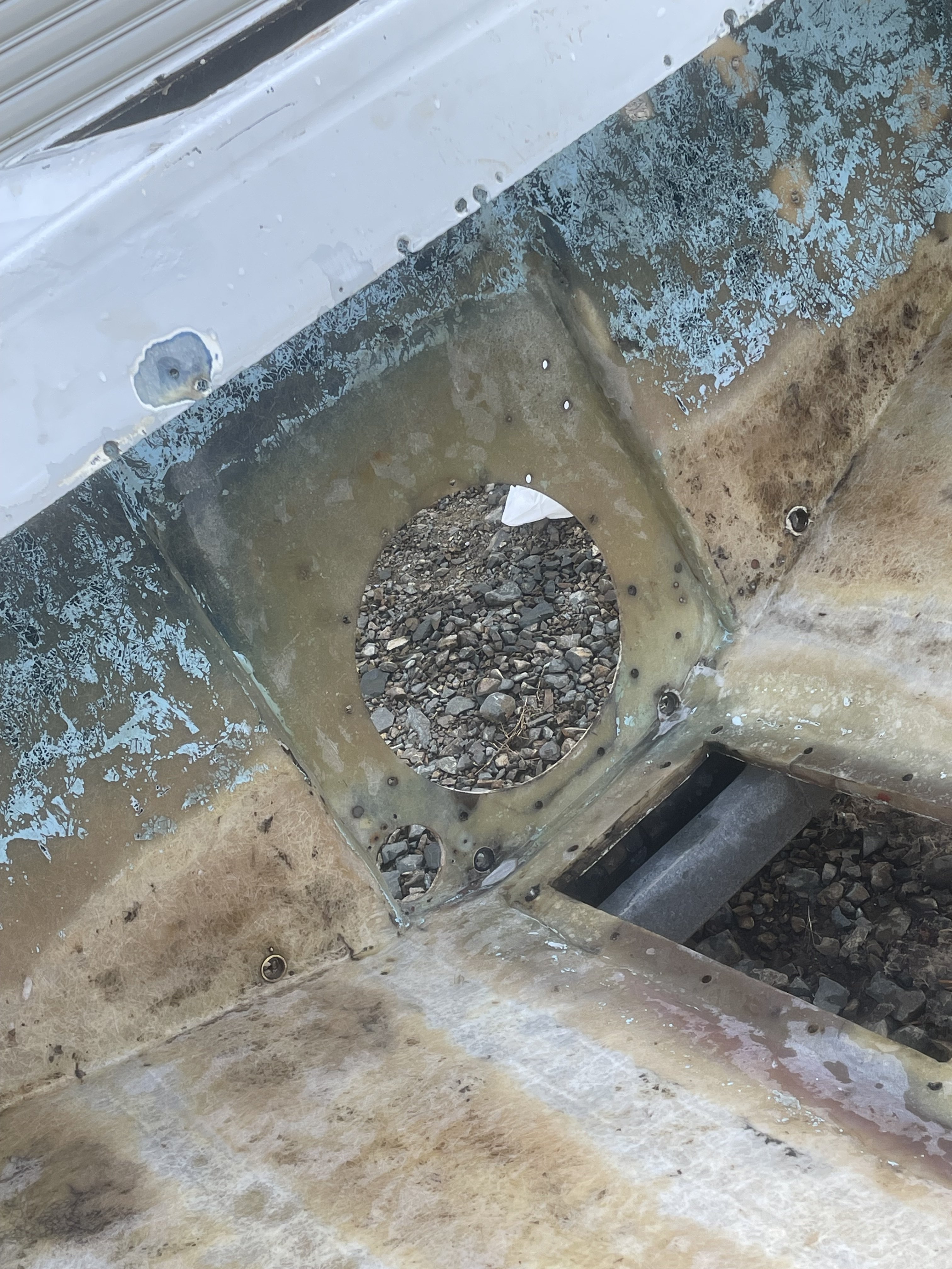
@Ned came and scanned the floor to be able to make new beams and a new floor, Also fanboat Brian came over and convinced me to stop being a weaner and cut the last peice of wood out of the back. all the serious misery work is done for now, will make up new beams and floor panels then probably get a friendly boatbuilder to glass them with a chopper gun as it’s not a performance machine.
1 point
-
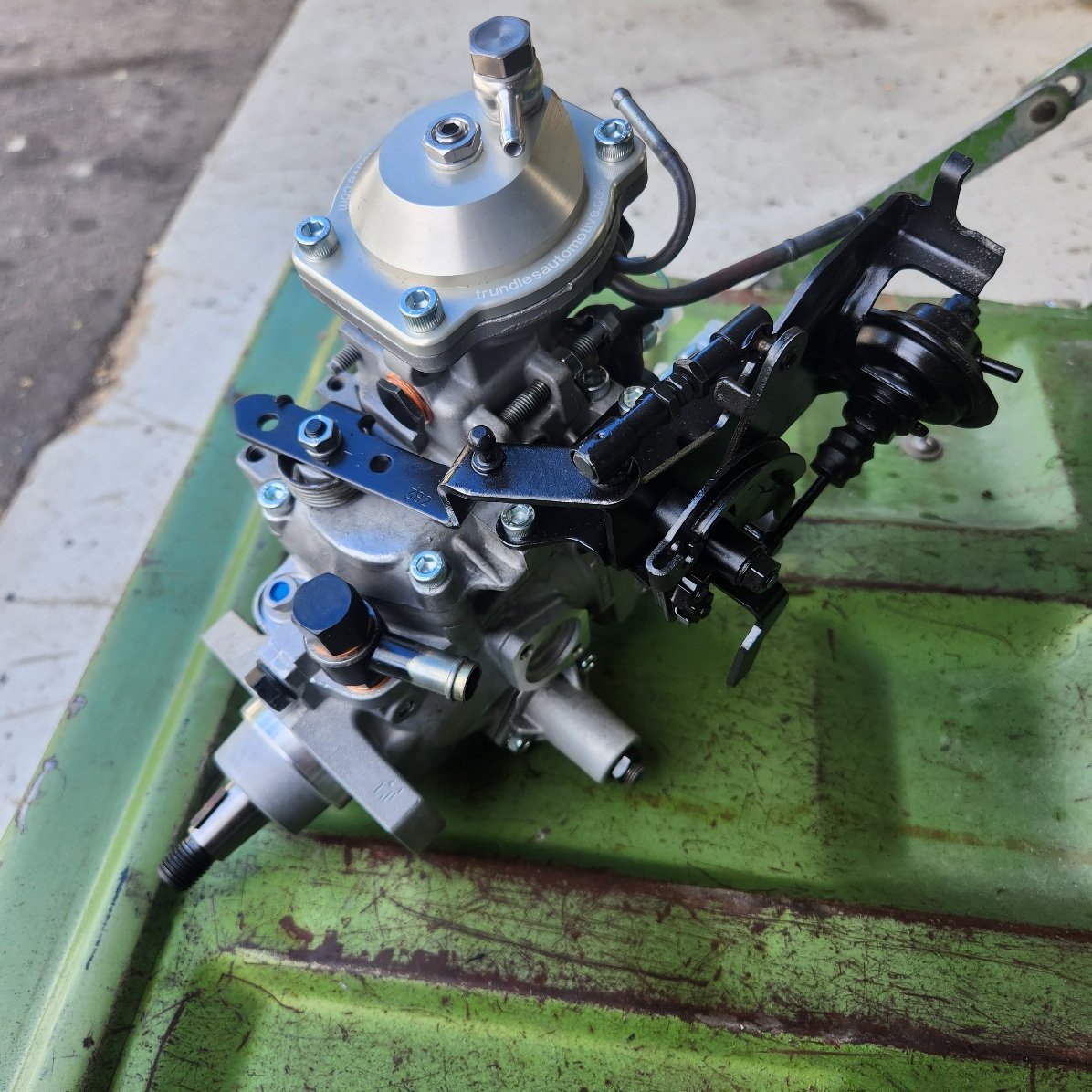
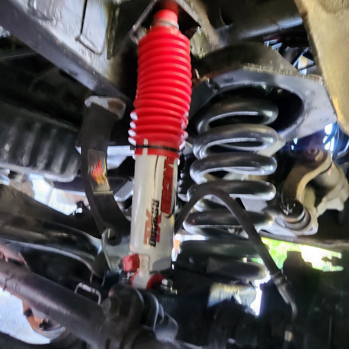
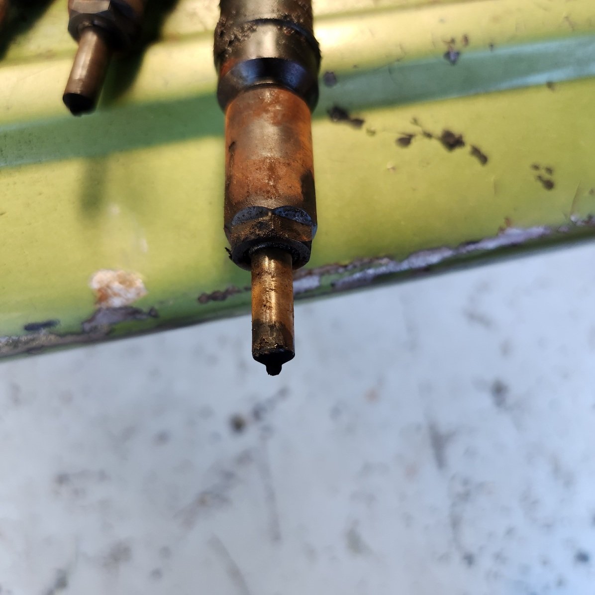
I've been getting some miles on this pig, it needs more power, it hates wind when towing and it was undershocked something wicked. Anyway did some camps over new years Twas good, wanged some adjustable ranchos in up front which dampen bumps out great, it still dives a bit but I'm guessing that's just lifted van life with a bit of travel and me sitting over the axle. But towing boat home today the power was really pissing me off so I whipped out injectors and injector pump. Pump will get overhauled and output pumped up via a reshaped metering pin, and injectors looked spectacularly nasty so I'll get them up to trundles this week for some lovin too, hopefully this makes a big difference. Also steering lock is shit, I hadn't checked the stops properly and it's not hitting the hub ones, just the box limits. So I've got a longer Pitman arm blank coming and will get it machined for a ball joint, itll be 15mm longer which should cure my problem Still no word from the certifiers, I'll start hassling them again next week to try and get it looked at.
1 point
-
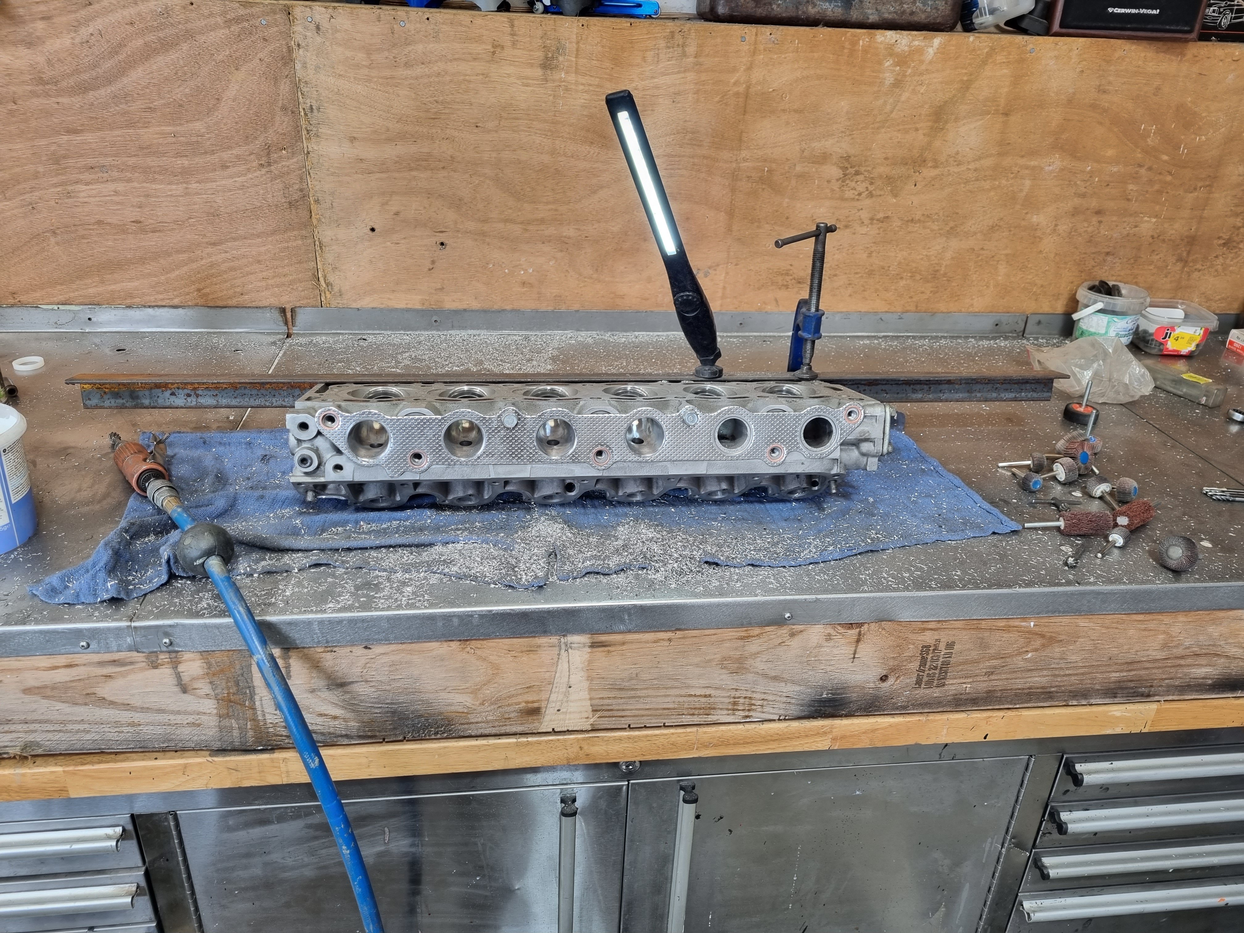
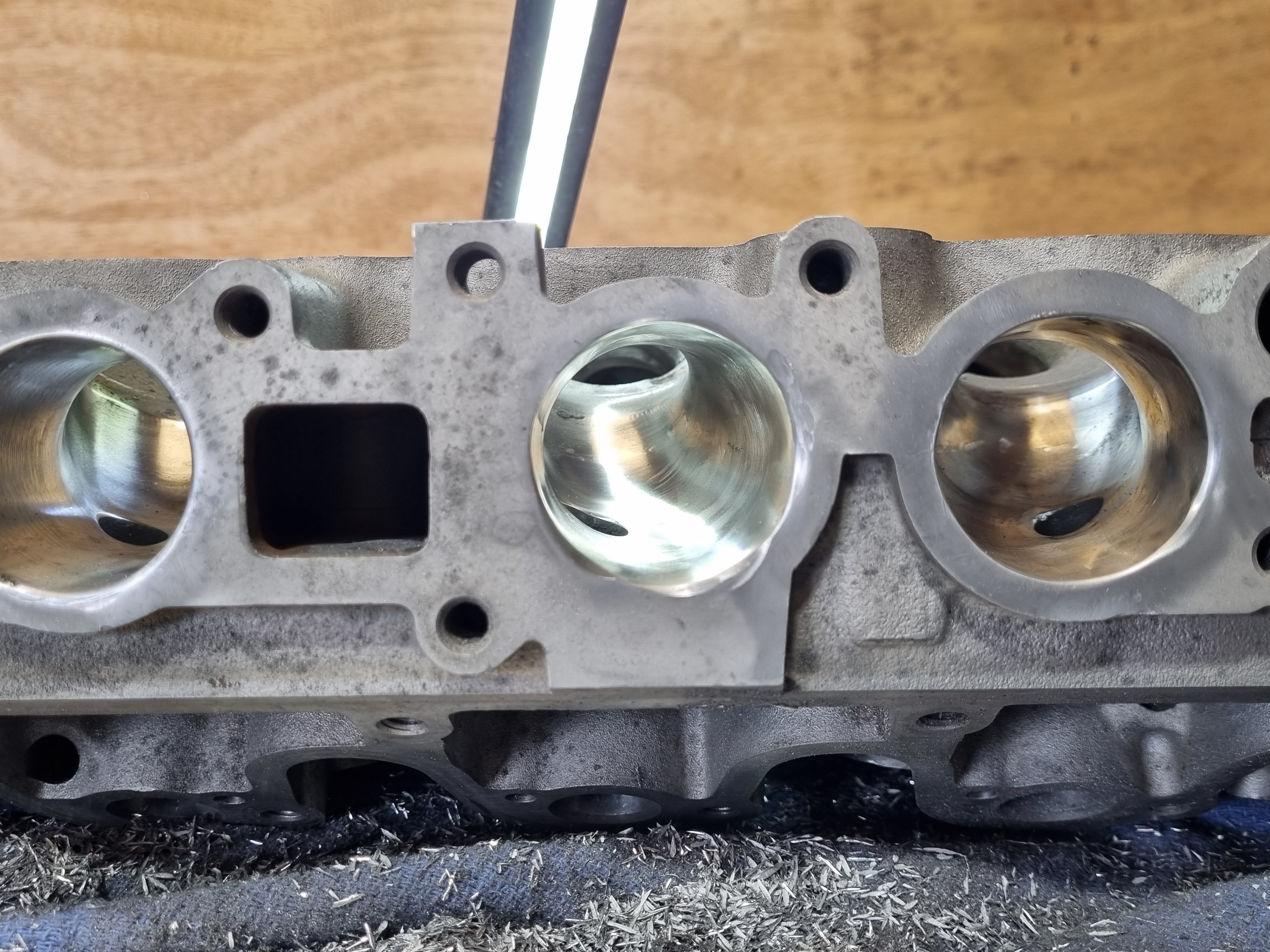
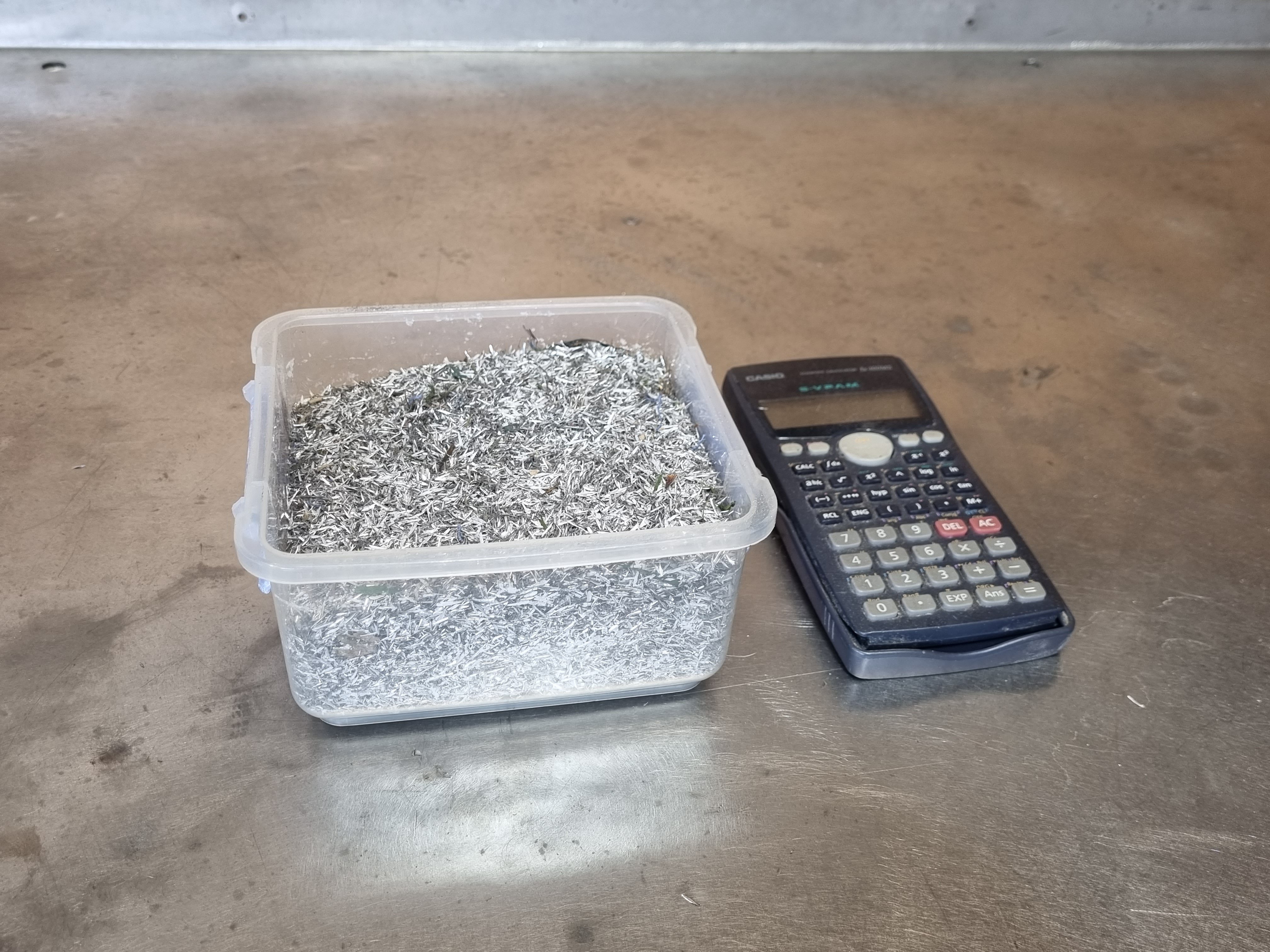
all finished. was a pretty messy job and took two days but its done now. i removed 400g of material from the ports. it will be interesting to see if it flows any better. ill get it back on the flow bench as soon as i can and see how it compares. fun fact, i ported one of these heads about 25 years ago and i cant remember how crazy i went with it (im guessing not very) but it made no difference to the motor at all. tbh that motor was a stock turd with stock intake and exhaust so porting it was a fucking waste of time but that was the style at the time. i think i planed the head to try to raise compression but that's a waste of time too given the stock piston design. ANYWHO, thats done. i took the exhaust from about 31mm to 37mm and removed a fair amount of material from the bowel, the intake went from around 31 to 38mm with the same stock removal from the bowel area.
1 point
-
When it's finished. The radiogram has been stranded on top of a table in my back room for the last half dozen years. I literally cannot move it - I live by myself, it's heavy and too big to get my arms around. I can't really take good exterior photos of it in its current location, and the exterior isn't changing much anyway. I'm trialling various badges above or below the display window, and I'm considering ditching the original knobs in favour of these shiny ones: I've cut more pieces of mirror to line the backs of the booze cupboards (originally there was just a single piece of brown chipboard over the whole rear of the cabinet). Over the years I have bought a couple of decanters (for class) and various skull-shaped vessels (what class?). No genuine old crystal decanters though, in case the lead leeches into my booze if I use them for long-term storage. I must hunt down some decanter tags. One day when the project is done, I'll bribe someone to come and help me carry it out to its designated spot in the living room for some beauty shots and videos. Then before I get the camera out, I'll celebrate by trying absinthe for the first time.... ....turning on whatever tunes seem appropriate... .... getting hammered and tripping out to all the pretty lights.
1 point
-
Re-torqued the head, re-did a ticky tappet (still ticks…grrr) and then put the bonnet back on. Looks like a proper car again. I need to sort the rear wheel clearance so I can go for a decent drive. Here’s some overexposed late afternoon potato pics. Front springs have settled well. What say you?
1 point
-
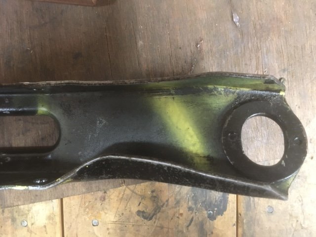
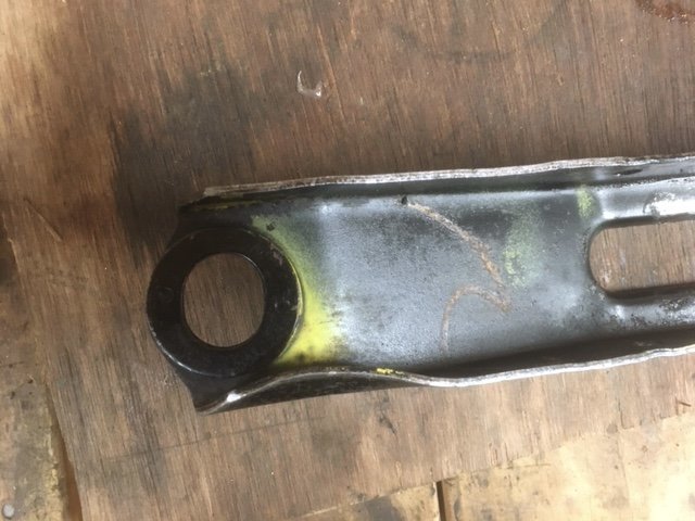
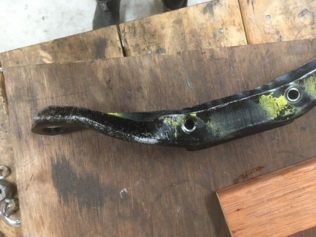
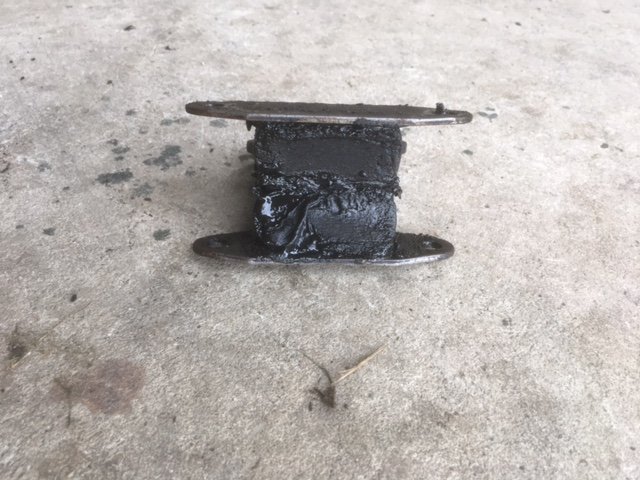
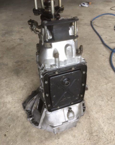
Today I thougt I might clean the gearbox so it’s ready to go when the time comes. This culminated in spending 3 hours with Exoff, various scrubbing tools and the water blaster. I guess I had forgotten how truly filthy it was, I mean it would have made a Land Rover blush… Readers may remember I had noticed the crossmember and corresponding point on the chassis were a bit bent. Er, more than a bit it turns out. It’s amazing what you can see when stuff isn’t covered in greasy filth. Yikes! Also check out the gearbox mount. It’s about the consistency of cheesecake. A combination of vice and large hammers got the crossmember straightened. It’s now in the acid bath for superduper cleaning. I made a tool for my slide hammer which in concert with my biggest ball pein carefully straightened the chassis rail. Great success. And check out my shiny box.
1 point
-
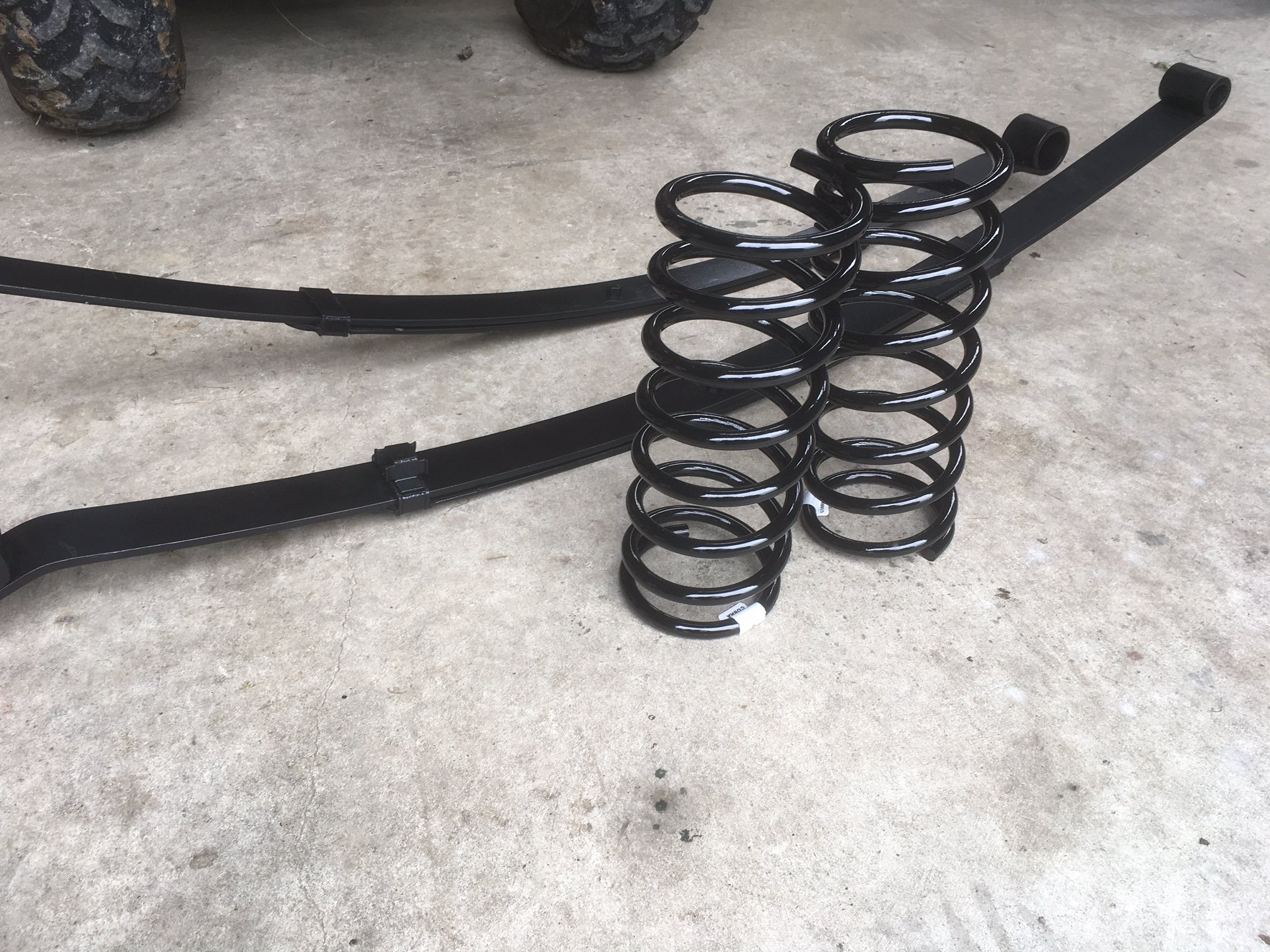
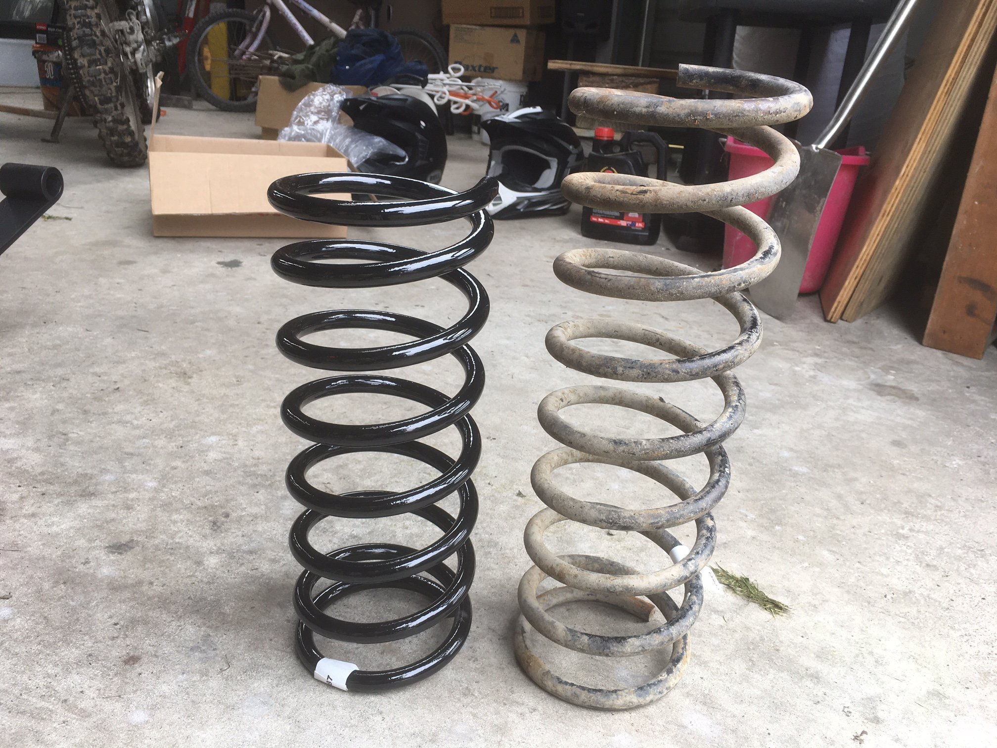
More goodies to pick up! Custom made coils and reset leaves. New vs old: And fronts installed! The leaf mounts need cleaning and painting, so aiming to have it on its wheels next week.
1 point
-
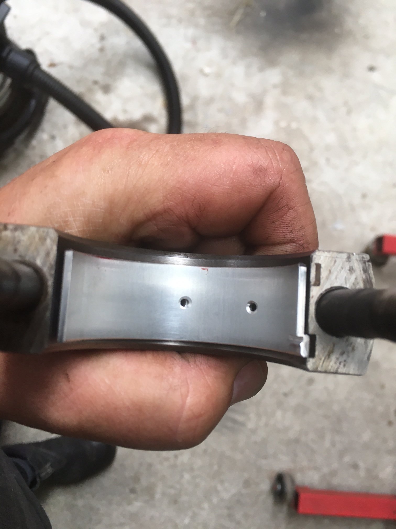
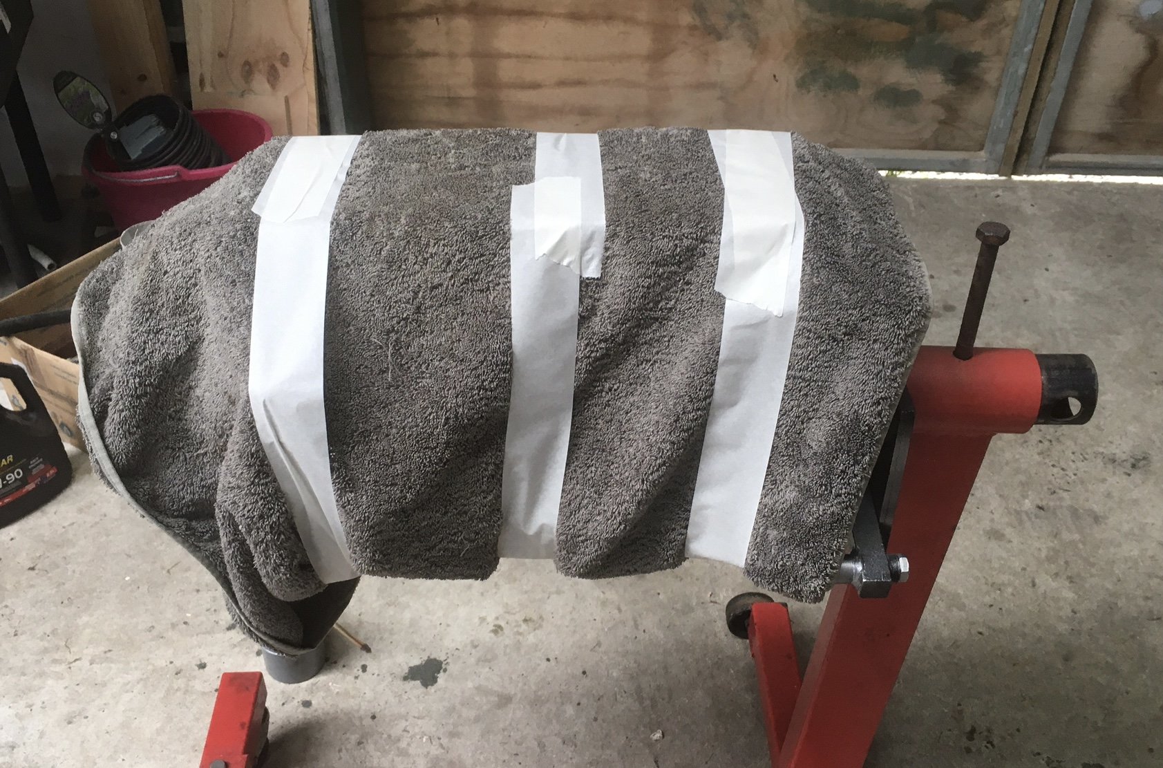
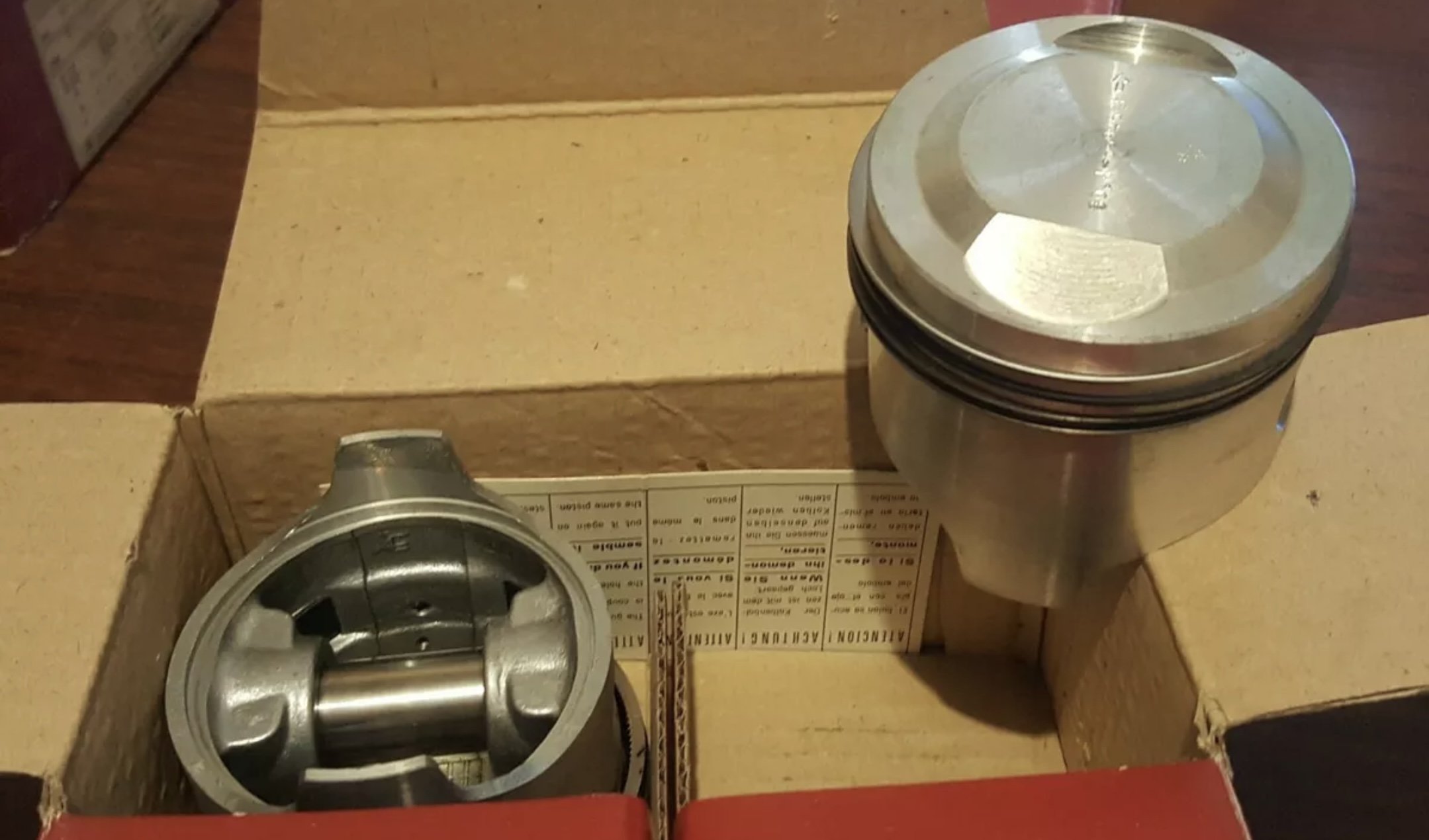
Next, I was fizzing to drop the pistons in, so I unpacked the big end shells and….OH NO…. they’re for the wrong engine! I’ve emailed the supplier and he’s looking into it. This won’t be a quick fix because Christmas and they came from Western Australia. 2mm too small: There’s not much I can do except wrap the engine up and try to keep dust out. As an outlet for my anger I decided to remove the cooked-on sump gasket. Twist knot cup wire brush 1, old sump gasket 0.
1 point
-
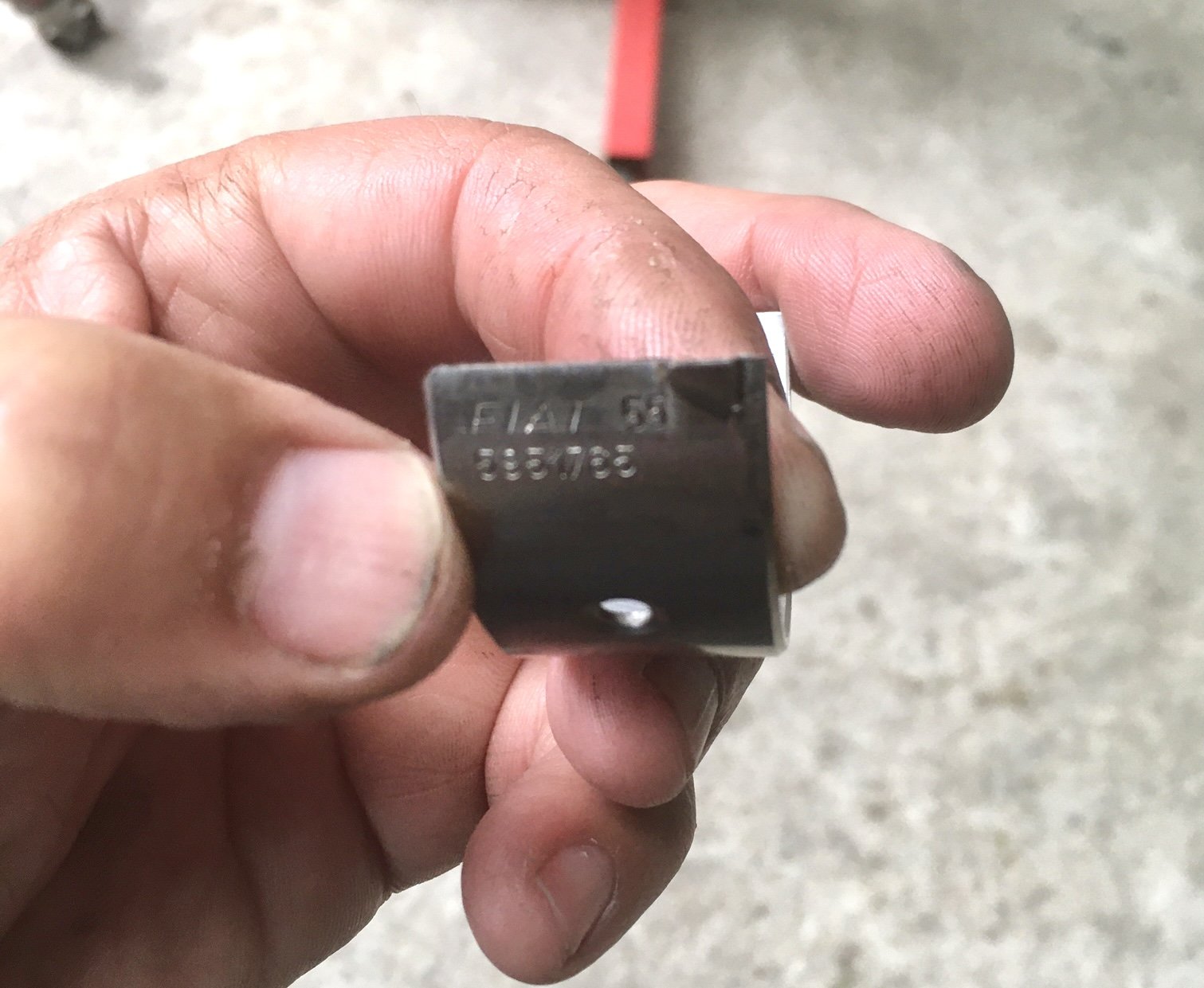
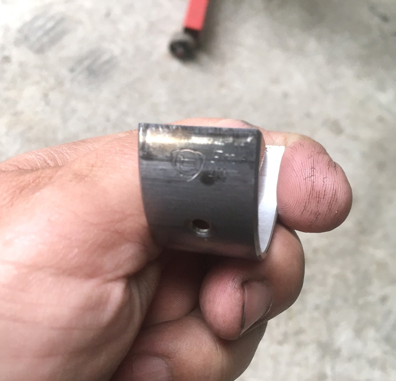
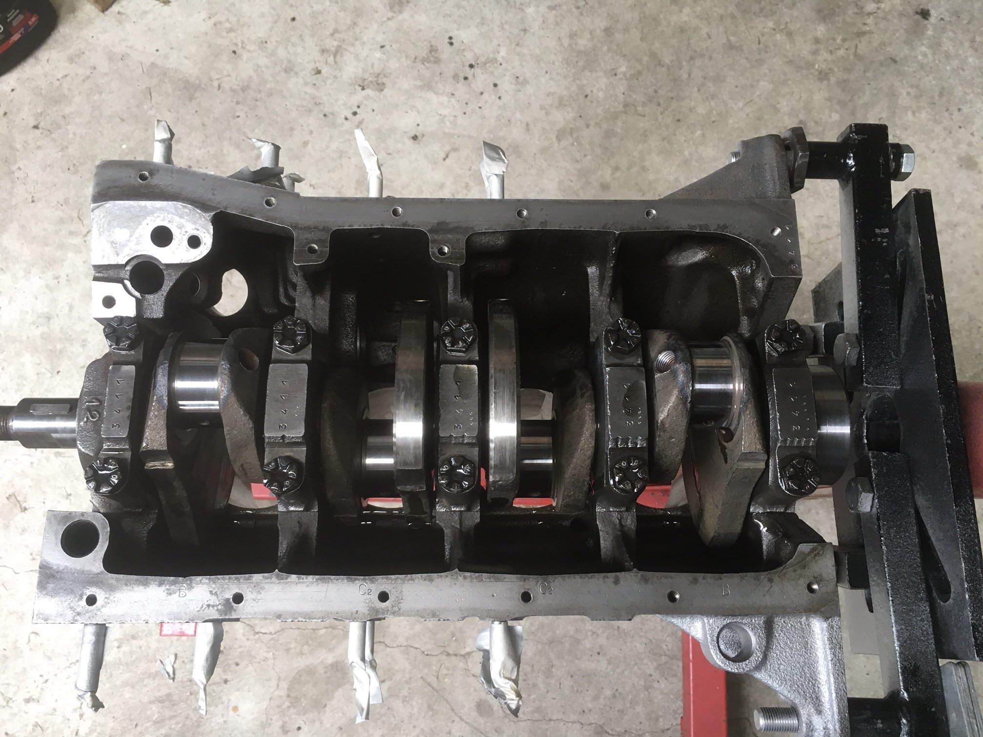
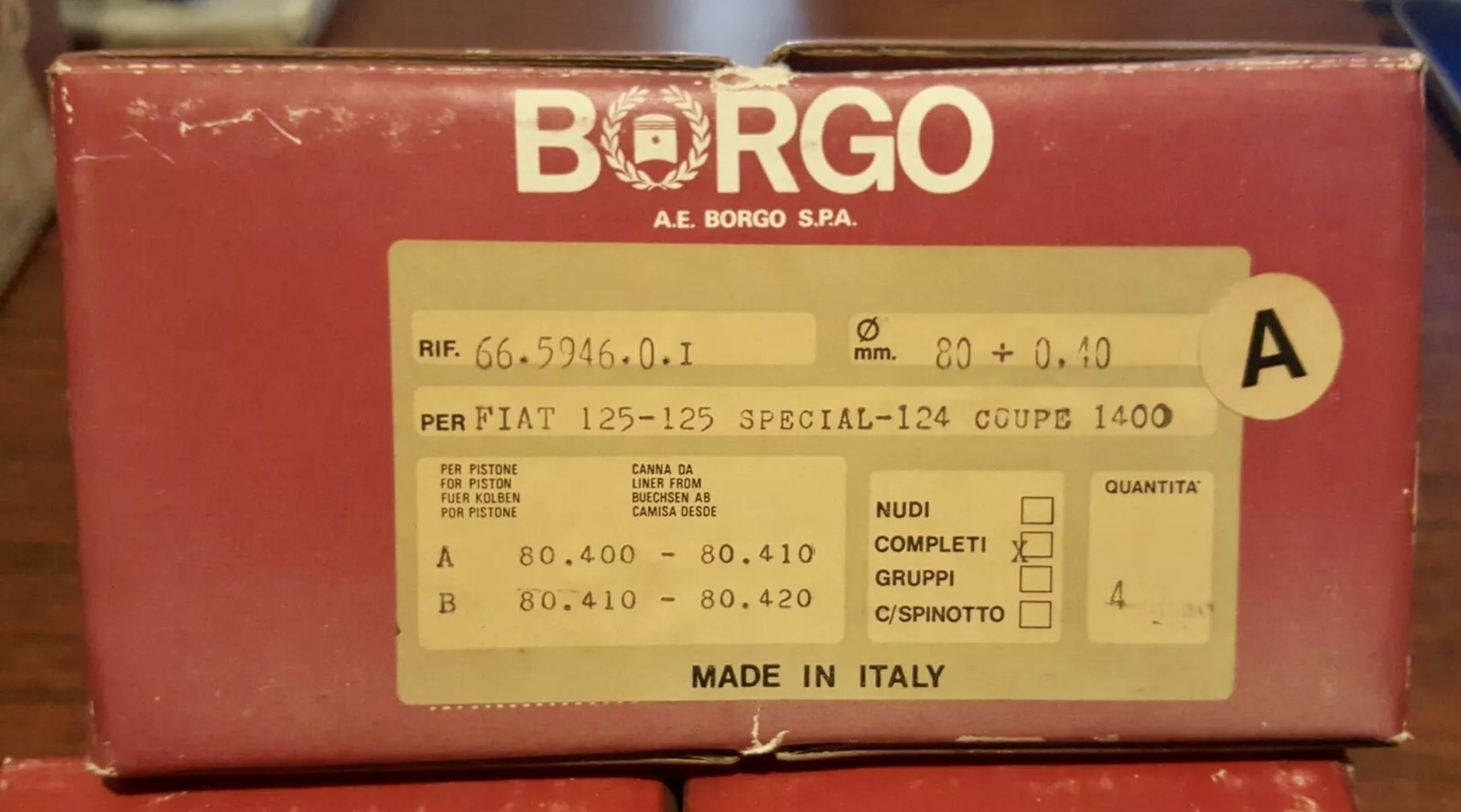
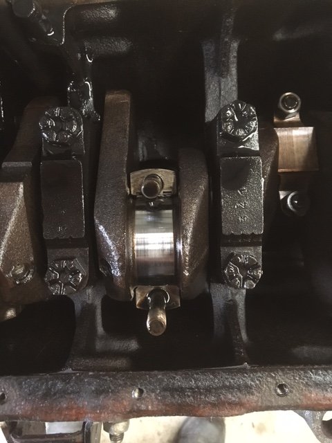
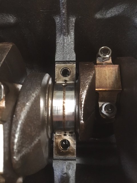
I cannot however, wait a week and twiddle my thumbs so let’s put some bits back in the inside. Time to open some decades old packaging. Check out the Fiat and Lancia engraving on the shells. I love NOS. It’s quite satisfying to pop in the shells, smear on the lube and finally nestle the crank in place being careful not to knock the thrust bearings out of place. Caps torqued and crank still turns smoothly, yay!
1 point
-
Significant wallet-lightening action has taken place. These are on their way from Straya. Also NOS main and big end bearings.
1 point
-
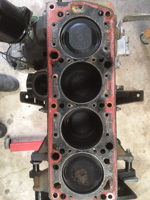
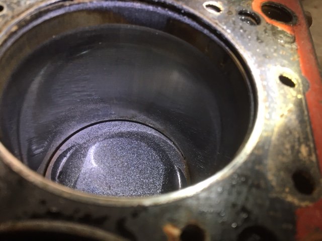
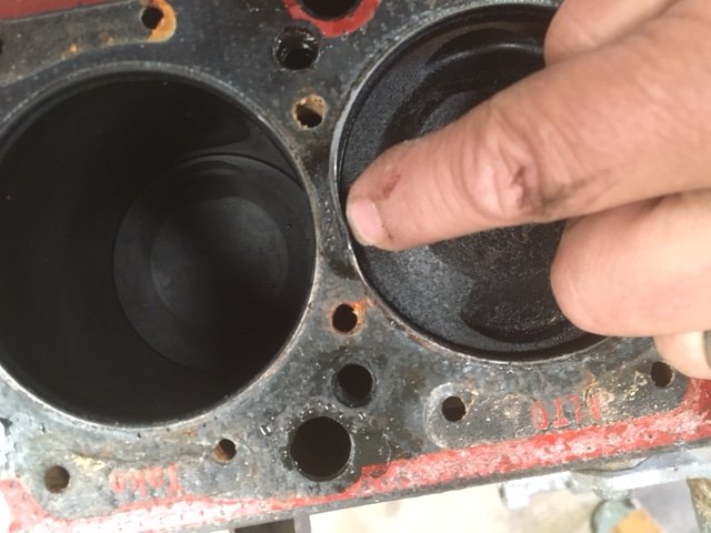
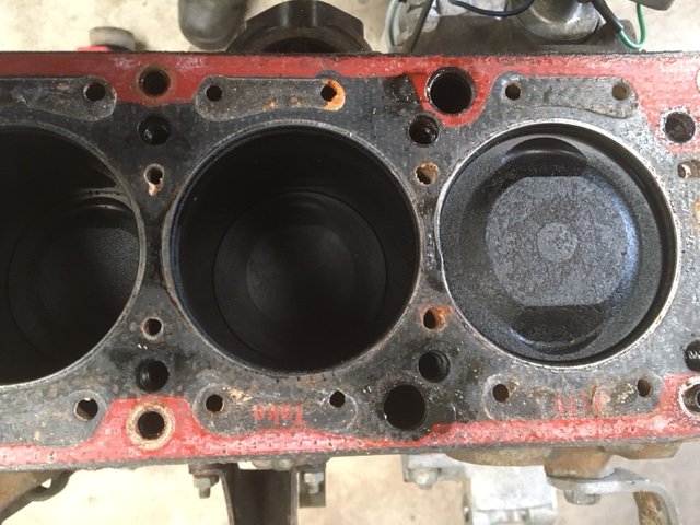
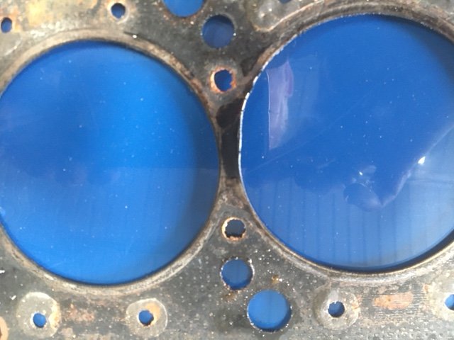
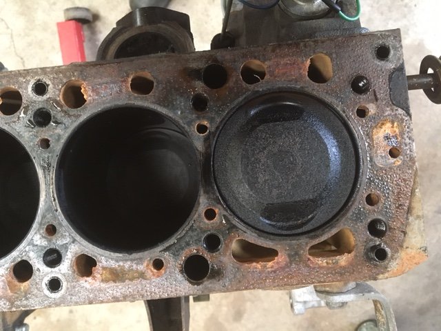
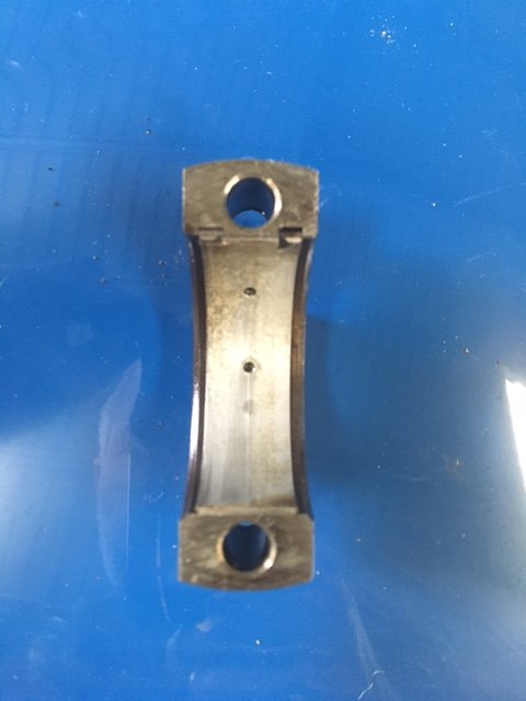
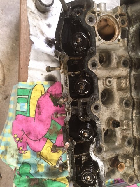
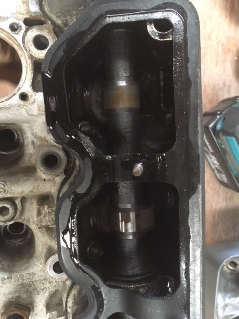
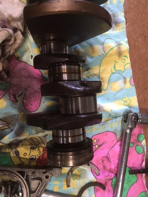
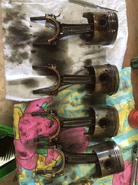
Photo dump! I doubt this is the O.G. gasket. Bores are well glazed too. Some marks, but can’t really feel them. The gasket is damaged… Underside, check out the scorch mark: Mark on the head between 1&2 (left of following pic) Scorch mark on block Big end cap, bearing has faint scuff, but can’t feel anything. Big end journal: This is where it gets uglier. Main cap & bearing. Check out the dark marks on the edges of the bearing: Main journals have black skid marks on them. I can’t tell if they’re damaged at this point, or if it’s deposited burnt oil. Cam boxes are FILTHY, however the exhaust cam is quite a bit less filthy. The cams have a lot of end float, but there’s no specs for it in the book. Crank end float seems fine. Finally, the pistons look like standard size, they have very gummed up oil rings but most worryingly they are very tight on the gudgeon pins, the rods won’t swing at all. In fact it takes a fair bit of force to rock the piston. Something aint right. Aaaand I accidentally dropped number 4 on the concrete. Looks fine though…
1 point

.jpeg.dc79046ad09d73b9fdc8de9e6e6d9c09.jpeg)


.thumb.jpeg.e0a4bff61111e0c8c7396950fcc94da1.jpeg)


.thumb.png.b2aee08688778d18bdc7b3e3c1852d9c.png)
.jpg.3db62282fa54b73caae93a320233ea4a.jpg)

.jpeg.aa059a0362a26e6af1f287df460bd1ee.jpeg)


This leaderboard is set to Auckland/GMT+12:00