
Leaderboard


Popular Content
Showing content with the highest reputation on 05/12/21 in all areas
-
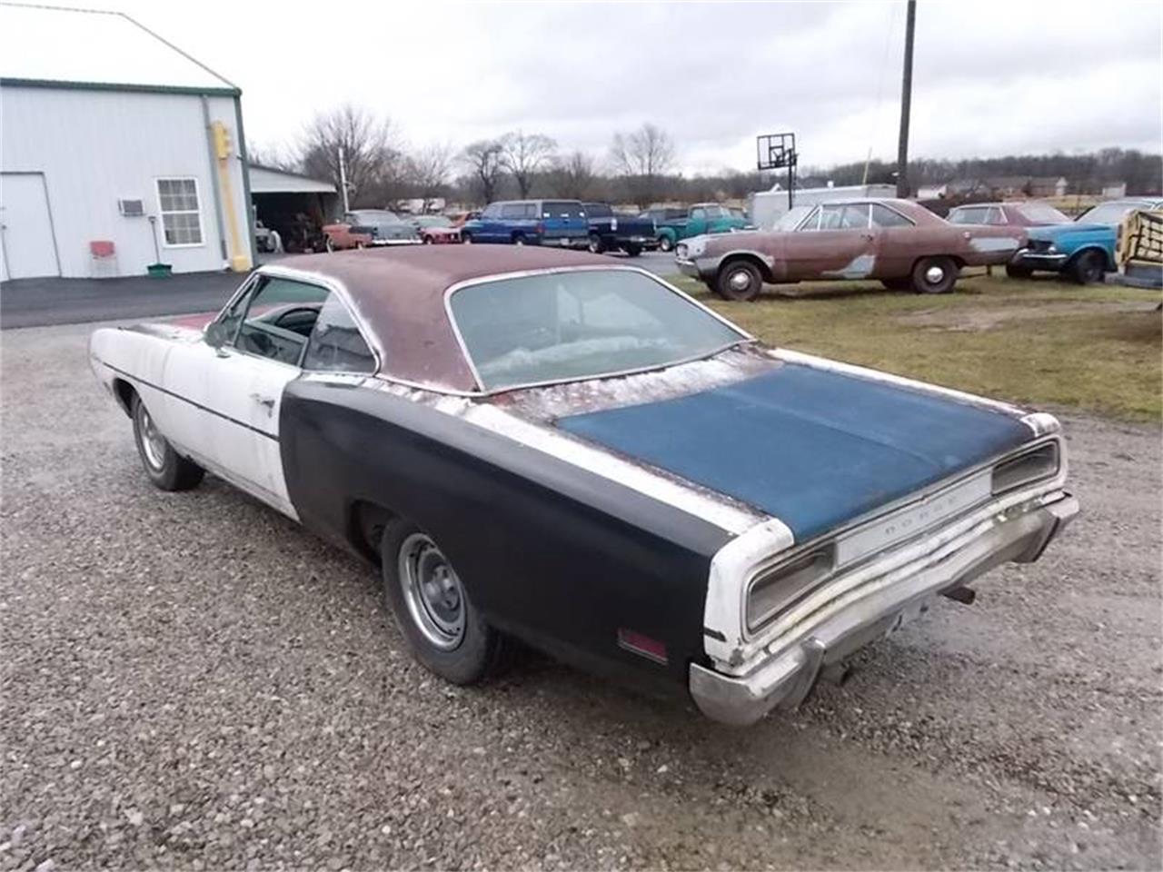
Gidday, me again with the crappy volkswagen. so last time we left off that i got it out side. WAHHOOOO the next thing on the list was tires and to dial in the ride height. i had messaged seedy al a we while back and asked what size tire he ran on the front and i run these also but this time i fired him a message to see what he was running on the back, and yikes it was a small tire compared to what i was running, which was a 205 70 14, i done some tire comparisons online to find something that would give me a smaller tire but nothing to small. I ended up with a 205 60 14. this is 22mm smaller in the side wall, allowing me to go a little lower with out having to ram the tire up into the guard. but since going lower i now have a lot more toe in, now causing the tire to catch on the spring plate adjuster. so i got some shims from bunnings, yes bunnings stock shims for vw kombis (washers). what i needed to do is shim the spring plate out a bit from the arm to help correct the toe in being this is one solid arm with no adjustment. this required a bit of fucking around, with the 1st attempt having to much toe out. so i removed a shim (washer) and put it all back together and it seemed pretty much bang on. So i got my 3 meter straight edge and drew some lines to the front and back and chucked a tape measure over them. i had the wheel alignment 5mm toe in. this measurement was comparing 2 meters behind and 2 meters in front of the wheel. so i thought my 5mm was pretty bang on for something that is not really adjustable. picture of the solid arm which i placed shims on to correct my toe in issue ^^^ this is the rear i placed spacers where the arrow points With that all done i was able to actually drive it out side and down the road a couple of times. was good to finally have it out side. I was using it a bit here and there to see if anything was an issue or i would need to adjust anything a bit more. My biggest issue was i was not able to select gears that well, i was really starting to get pissed off about this. got talking to the guys at v-dub shoppe and they gave me a bush to replace in the gear linkage system close to the gear box. fucked one this little guy was toast, it was ment to be solid and have no movement but it had about one 8th of adjustment in it causing it to no select gears correctly. replaced that and OMG what a change! while i was up there i got this image of it all done. next up i proceeded to loose my drivers side hub cap about 4 times with in 10kms from home, found it each time which was a bonus. next i needed to sort some shocks out for the front, while i was out at @Fuckedifiknows house i was talking about what i needed to do and he passed me these. and then i got some shocks but i was going to need to do something as the shaft was to big for the bush on the shock. well we had @Kimjon pop in and take my vespa for a ride and he suggested he take them home and chuck it in the lathe and take a few mm off it to make things easier. finished result! next up i needed to tap the shock tower so these could go into them. she was a tight squeeze but we made it work. time to make some bump stops for the front and the rear. front ones go a little like this. put some holes in them make sure the holes line up then you get them lazer cut and leave them for 2-3 months back ones go a bit like this remover rubber dog chew toy (way before we started this) Get smaller rubber chew toy make small rubber chew toy screw into metal thing thanks to @Geophy make metal thing that rubber chew toy screws into be one with George the kombi glad i still know how to melt metal together not that well. so paint metal thing black and screw little chew toy in also removed the big cup thing off the rear control arm for more clearance so i have a bit more travel before bump stop hits, this was only held on with 2 little tac welds so i feel like i done good here. now when it touches a good solid peace that wont fall apart. done some other things to make clearance issues not an issue but i wont show those as i didn't take photos....... but here is a photo of it allll done. do you guys like the no hub caps? or with the hub caps? visited my mates out at the v-dub shoppe to show of and thank them heaps for all their help. and our next adventure was to the bay of plenty to see some vdub people and inquire about getting the kombi checked over for a wof. the bay of plenty was great to us. chilled out with beth and tayla before visitng the wof place. re done my wheel bearing while i was at the wof place cause it was making some noise and then headed out to catch up with a vdub mate brought some rego and went to take a comparison photo when i got back home. thats it for now. next time on adventures with the 64valiant family and George the kombi we head to beach hop and vw nationals. stay tuned24 points
-
things are pretty great with this car. just got to sort out the seats and some carpet but thats for another day. i bought some new rear disks for it a while back because the ones i had were turbo fucked. minimum thickness is about 11 mm and one was down to 9. so yea, in they went. not a big job but still. 2021-05-01_12-59-34 by sheepers, on Flickr 2021-05-01_12-59-28 by sheepers, on Flickr11 points
-
Just me then ? Oh well, I should probably give up the modelling bit & just stick to sniffing the glue and thinners. It's nice. Got an hour in tonight, sunny weather & lots to do is not exactly helping. / pics Going back up-country again in a couple of days so will bring the 1/24 Caddy back & have a bash at that.10 points
-
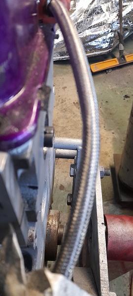
pulled it to bits and got it ready to remove the motor. ive ordered some parts which willtake ages to get here so im in no hurry. i thought id tidy up some stuff while im waiting. water return pipe from the turbo went into the original spigot and the second one was just blanked off. it looked a bit dumb so i pulled the stainless tubes out, welded up the holes and welded a dash 6 nipple on lower down. 2021-05-09_07-04-13 by sheepers, on Flickr 2021-05-09_07-04-05 by sheepers, on Flickr then i thought id make a new, smaller radiator reservoir and windscreen washer bottle because real-estate in that area is real tight and its a pain in the arse to get to anything in that space. not finished yet but getting there. cut some 75mm box section put a pie cut in the bottom to help clear the body work better weld caps on each end sand them up a bit weld the screw caps in still got to put the inlet outlet fittings in and mount the little electric motor for the windscreen washers but that shouldnt be a drama. ill just hide it underneath like i did for the V8 2021-05-11_08-14-23 by sheepers, on Flickr 2021-05-11_08-14-29 by sheepers, on Flickr 2021-05-11_08-14-35 by sheepers, on Flickr 2021-05-11_08-14-41 by sheepers, on Flickr10 points
-
So, I still own this It got used for a daily for about a year or so, and I made a few more changes to it - t3 knuckles and modified the tension arms for more caster. And changed out the rear end to an 4.11 F code center from an mx73, with an Altezza torsen. Here's a terrible, old, cellphone picture of it about then; A little later while I was taking a short break from possessing a license I pulled the windscreen(s) out to fix up the rust that was coming along nicely in the lower corners of the rear screen frame, but didn't actually get around to actually doing that for a long time The 4a was getting pretty tired too - at some point i'd lost one of the filter socks and gave in and just ran nothing at all - so a life of hard work and then that, it was starting to experience pretty heroic levels of blowby. So was looking at doing a rebuild on that, but then I happened to be at Zebra looking for something unrelated, and found this in one of them mental WiLL VS doodads; A 2zz. No real idea what condition it was in but being zebra, it was cheap enough to get to just stuff around with Id actually already bought a j160 to put on the 4a - had a look at that, and the way a few key things on the 2zz were arranged (simple steel sump/pickup, easy waterlines etc) it actually looked pretty straightforward to make work in a rear wheel drive arrangement. Did a very rough 'adapter plate' to the j160, for a sort of proof of concept and threw it in the engine bay, it all fit a little too well I figured they already make 190hp standard, is all aluminium, has vvtli, gain 200cc, so why not really This is going back a little while now, and progress has been glacial (had a kid/wasting my time with other projects) but it looks something like this at the moment; Ignore the 20v throttles propped up with a bit of wood for artistic purposes but yeah it's mounted, the headers are now done, the j160 is more or less adapted, and the rust is fixed too I'll put up some more detail on that stuff soon discussion\tell me how stupid i am5 points
-
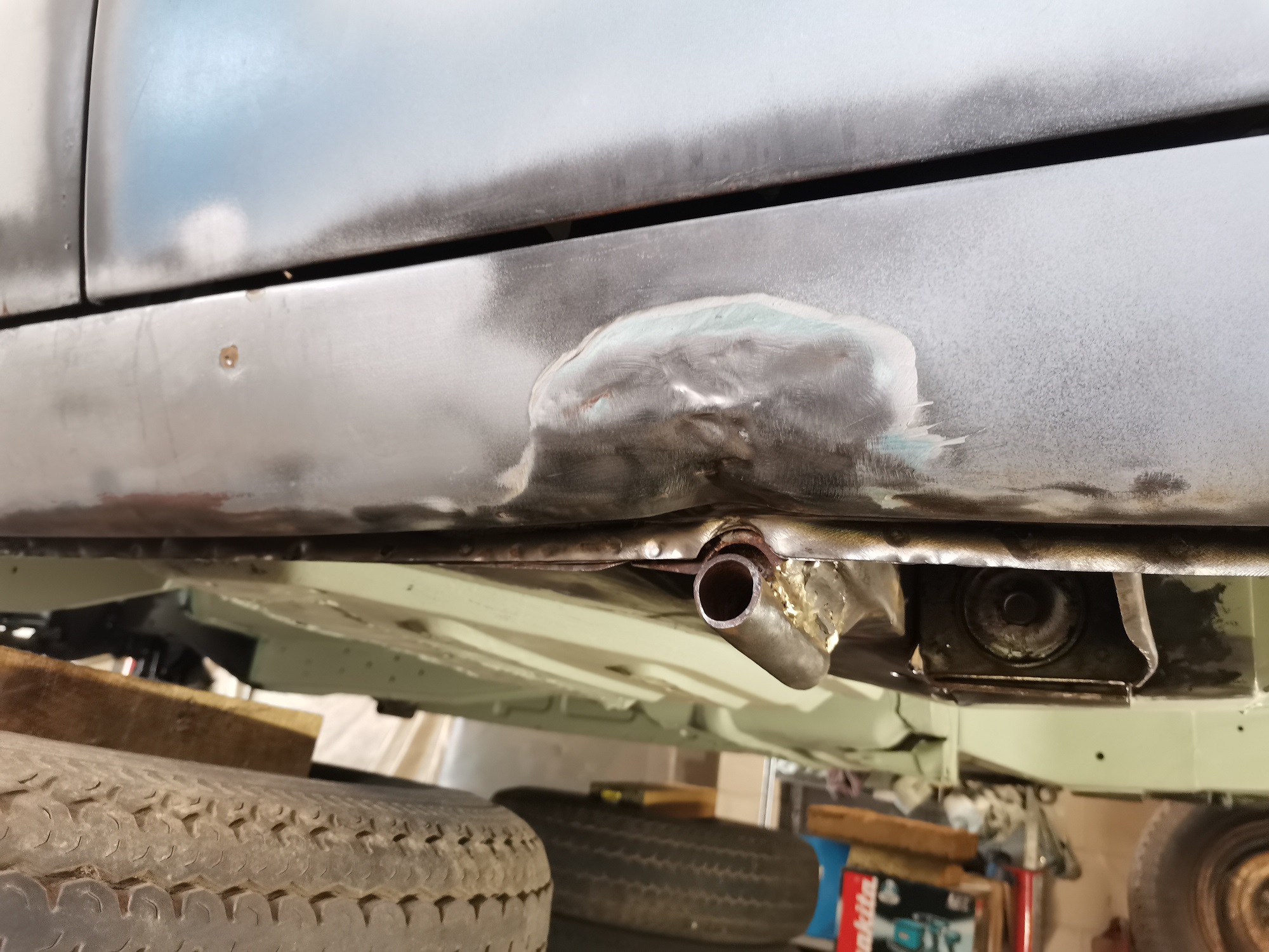
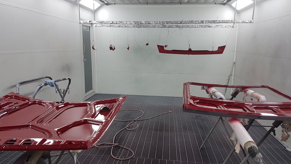
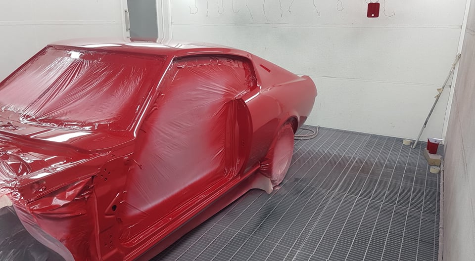
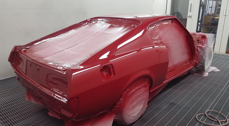
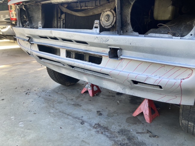
car went to the paint shop to get the runs out of it and get the final cut and polish. i went and picked it up last night and it looks amazing. anywho, today i wanted to fix the exhaust where the flex joint had worn through because its the lowest point and its had a fucking over judder bars and whatnot and subsequently has a hole it in. step 1 - jack up your car. this is where things went wrong. 2021-04-25_02-55-42 by sheepers, on Flickr car slid off the jack on the way up. given what could have happened i got off extremely lightly. it bent the radiator support up and bent the bottom of the radiator real bad. it also bent the bottom of the front bumper. however, the radiator isn't leaking and the crank pulley is unscathed which is a fucking miracle given what happened. i was able to bash the rad support back down and i got most of the bend out of the bumper so it looks fairly normal again. fuck it could have been WAY worse.................. so yea, after dealing with that i moved on to fixing the zorst. cut out the fucked bit, made a new bit, tacked it in place, remove zorst from car and fully weld, add 4mm thick bash plate and put zorst back in car. 2021-04-25_02-55-49 by sheepers, on Flickr 2021-04-25_02-55-55 by sheepers, on Flickr 2021-04-25_02-56-02 by sheepers, on Flickr 2021-04-25_02-56-09 by sheepers, on Flickr 2021-04-25_02-56-21 by sheepers, on Flickr then it was time to wax the newly polished paint. that went well. it looks pretty ace tbh and yea, i cant take a photo that justifies how good it looks. but it looks good. take my word for it. 2021-04-25_05-34-27 by sheepers, on Flickr 2021-04-25_06-18-48 by sheepers, on Flickr 2021-04-25_06-19-23 by sheepers, on Flickr 2021-04-25_06-32-09 by sheepers, on Flickr5 points
-
I Zebra'd a new engine mount and also put the factory exhaust manifold back on, as the other one was leaking horrifically from everywhere. Then did a bunch of other things and got it fired up! Pretty chuffed with that, it's a nice feeling to not have it all blow up immediately. I reckon it's gonna be pretty rowdy with these cams haha. I then mucked around for ages and bodged together water and heater lines, filled it up with coolant, then.... fucked up. Despite my previous efforts I managed to wire the waterpump backwards and I think I let the smoke out. I fixed the wiring but now it doesnt work. Will be lame if I have to buy a new one, as they cost as much as this bloody engine did haha. Depending on the motor type I might just be able to bodge this one to bypass the variable speed and just run it full speed full time. Dunno. Aside from this. I really need to pull the wiring loom apart a bit, because currently the alternator wiring is baked into the loom up top, but it needs to move down lower. Also because the block is taller, my trumpets hit the bonnet now. So will need to make some new ones. However will all 3 of the polyurethane mounts in, it's now super rigidly mounted. So I can hopefully push it close to the available space without issues. But it was awesome to get it fired up anyway. I'm still a few tasks away from being able to drive it, if the water pump isnt fixable it'll be next month that I can buy a replacement.4 points
-
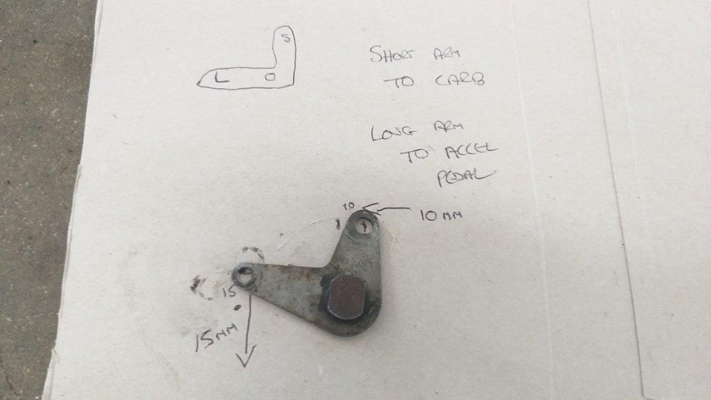
Now the eagle eyed amongst you will notice that the arms are slightly different lengths. I setup a little "test bench" using an old cereal box. Poked a hole through the box for the pivot bolt and ran a little experiment. For every 15 mm of travel on the long arm the short arm travels 10 mm. If my maths is correct this works out to a ratio of 1.5 to 1. Adding my original pedal movement figures of 45 mm to 30 mm into the mix, this just so happens to be the exact ratio that I require. If I was to connect the short arm to the cable and the longer arm to the pedal activating rod, I'm thinking that the pedal will need to travel further than it currently does and hopefully the longer arm will slightly reduce the force needed on the pedal to move the cable. Please shout if there are any glaring errors in my theory. Anyhoo, in order to give this a try I've got to fabricate a MK 3 version of my cable bracket, so that is the plan for tomorrow. Thanks for reading.
 3 points
 -
Gotta start thinking about rad and intercooler soon
3 points
-
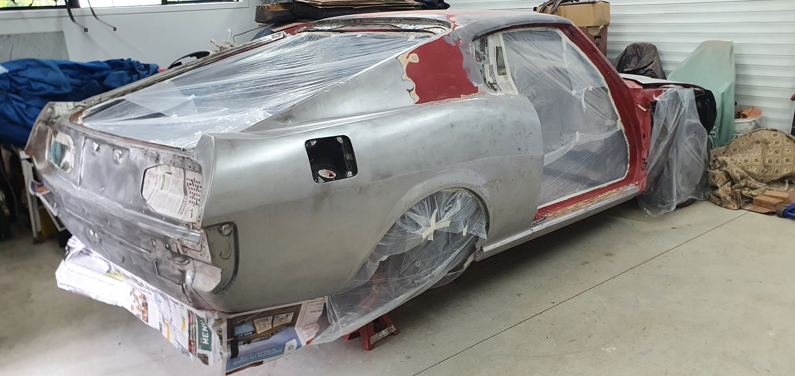
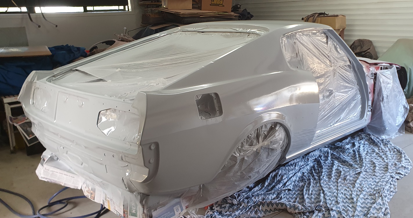
Took some more shots since it was out of the shed. She’s now at the blasters. Cancery upskirt3 points
-
@yoeddynz, you should start building it, your shed's big enough. That set-up in your video is pretty cool, 203 views now. Shigeyuki Mizuno is indeed a fellah and as you say, and a seriously skilled one. I was thinking about the whole super realism thing having looked at some stuff on the model forum and I reckon we get more demanding as we get older. As a kid you're happy to let your imagination fill in the gaps in your talent (or blank out the shag pile sticking through your train set rails). I think there's a ceiling to the realism, after that it's down to clever photography. I'm not a train person but was certainly impressed with Rod Stewarts layout.2 points
-
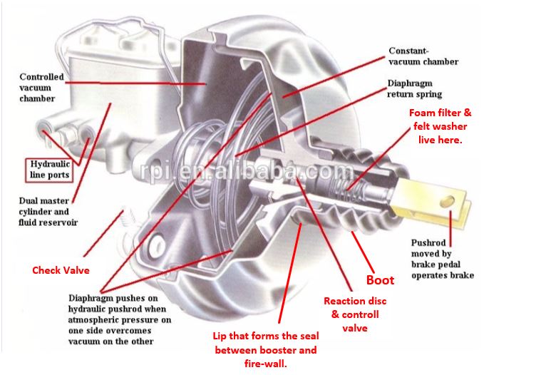
Sorry for the delay in replying - it is a bit of an unusual one for sure. One of the big improvements a Mastervac booster has over the older Hydrovac (remote) booster design is that it introduces the atmosphere from the inside of the car ( the drivers foot well) as opposed to the engine bay. I’ll just mention here that the major improvement was not relying on a single pushrod seal that the failure of which would often result in a total loss of braking – great innovation guys! The filter usually consists of two parts, a coarse foam doughnut and a felt washer where the pedal pushrod enters the unit. The filter sits in the valve body held in place by the felt washer which in turn is held in place by the rear boot. Sadly a lip on the boot forms the seal between the booster and the firewall and to access it you have to remove the booster and master-cylinder (sods law strikes again). I’ve doctored up an exploded diagram of similar Nissan booster for clarity, (alterations in red). Have to say that at this stage I’m clutching at straws with this one. Nothing new here; the more interesting diagnoses are usually the most baffling at their onslaught! Although an obvious conclusion to jump to I’m not comfortable with a 10 year old booster somehow “digesting” both filter and felt washer through overly vigorous brake bleeding. The ports in the control valve are small and the only Mastervac filters I’ve ever seen fail have been from early 70’s boosters that have lain unused for decades? I have seen boosters with a small perforation in their diaphragm still performing to spec but needing far more atmosphere than usual to be introduced to the rear chamber. It could well be worth pursuing this, I’d suggest pulling the master-cylinder back a little to see if it is leaking fluid into the booster, on many cars you can manage this without releasing the hydraulics. Please keep the thread going and let us know what you find.
2 points
-
Have you been hooning the Whakatane river? SunLive - Plastic spill into river investigated - The Bay's News First2 points
-
This months meet, 27th May at burger fuel the base.
2 points
-
Was expecting this to die 18 months ago thrashed snot out of it ran it on kerosene while i got it for free. Played with tuning etc its been through a lot and just keeps running doesn't burn oil or use water....... now ive said this it'll probably blow a head gasket on way to work tomorrow. Just needs to last till i get new engine in.2 points
-
It came from the states with new quarters screwed onto/over the existing ones. Great idea instead of trying to jam them inside then have them chaff through your interior etc/ slide into the glass but it sure did a great job of masking the despair aye
2 points
-
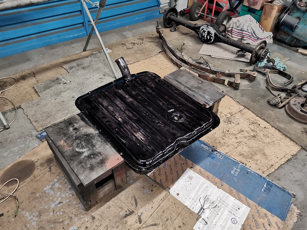
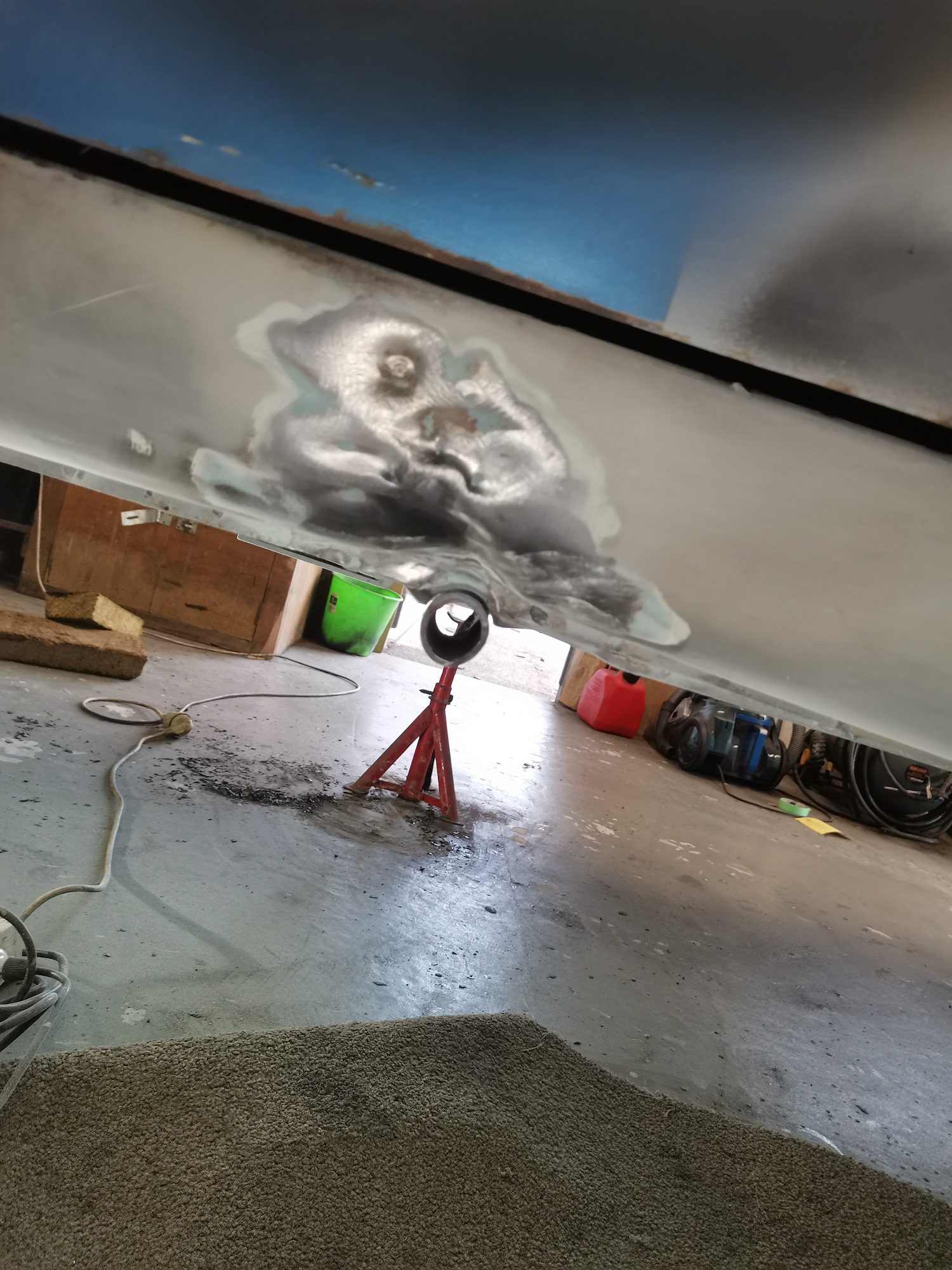
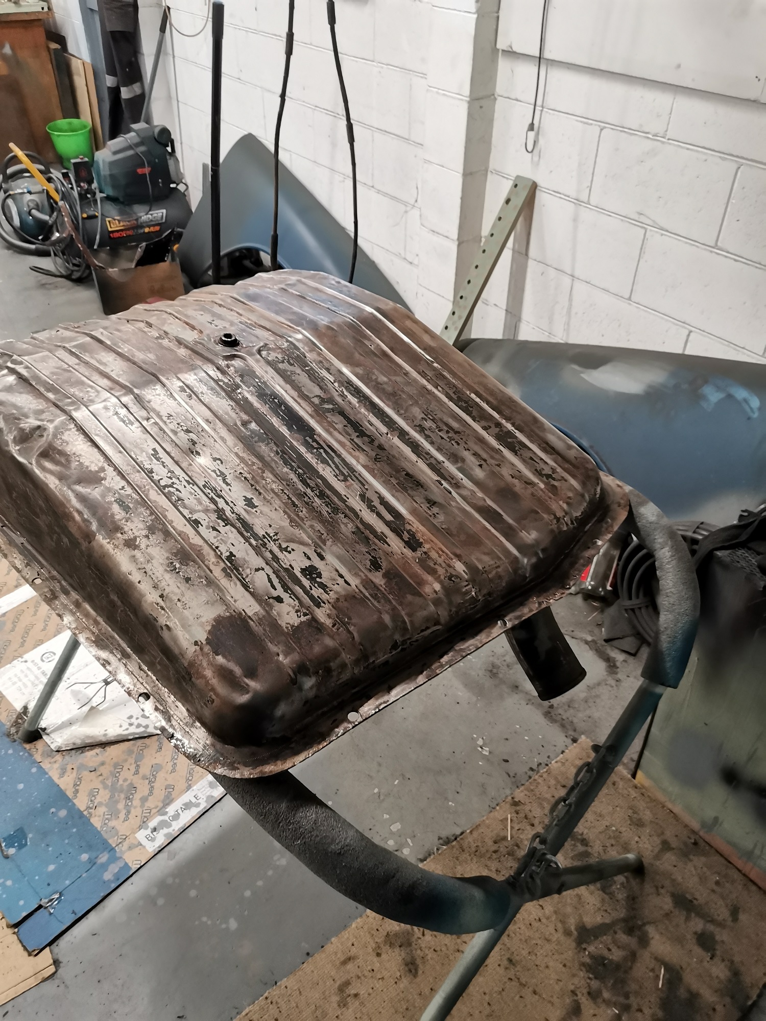
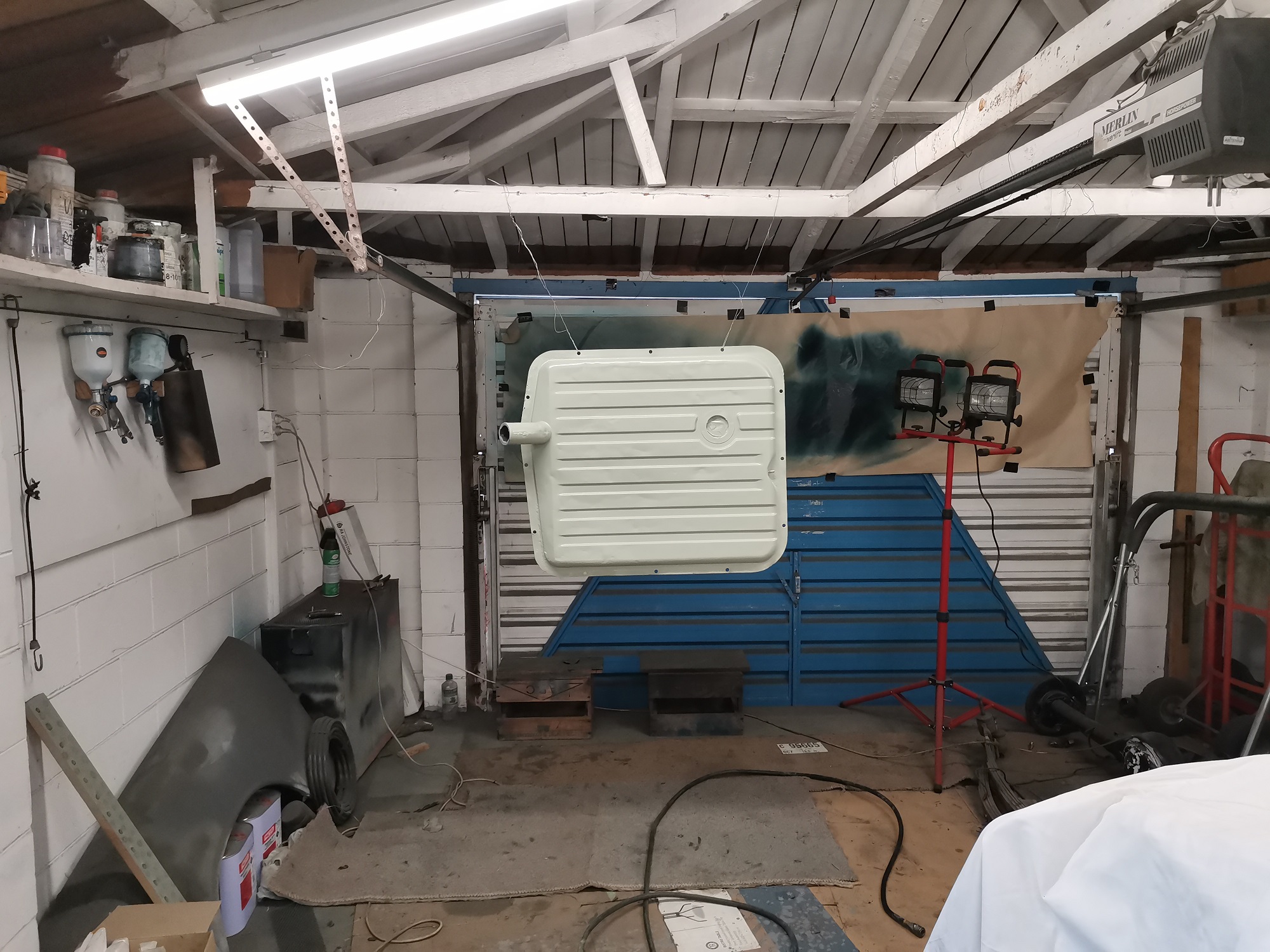
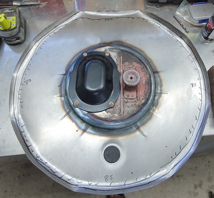
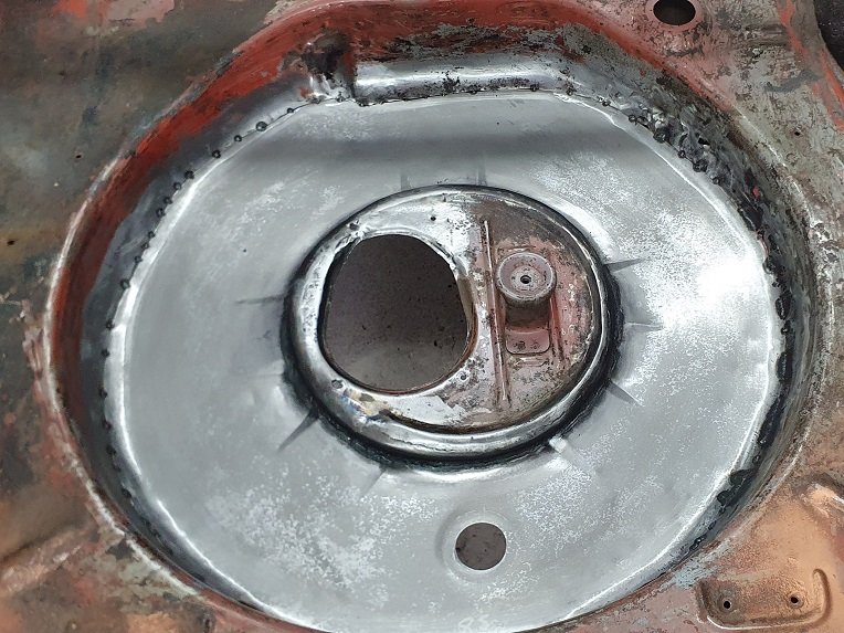
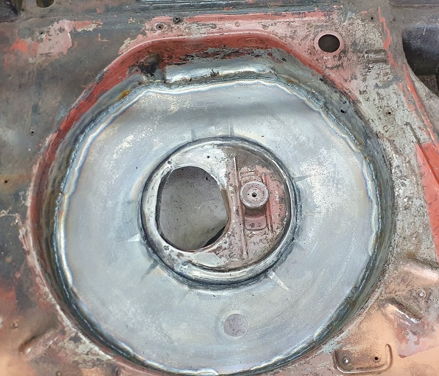
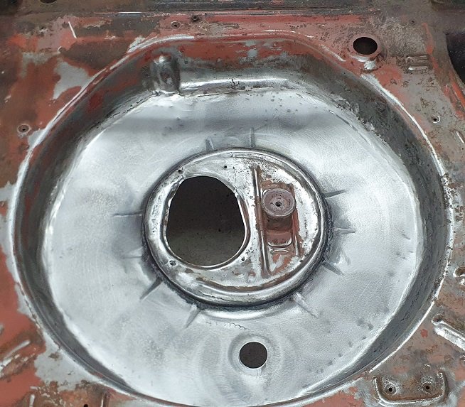
Got the fuel tank back. First pic is before it went to the radiator shop. Had the remainder of an existing liner in there, so he had to split it and sandblast to get the new liner to stick. He also knocked out the worst of the old dents, so I am happy with the outcome. Stuck some brunox on there and have got into epoxy. Found some denting on the sills which is a bit annoying. Guessing it has fallen off a jack at some stage, unfortunately it's got similar damage on both sides. Not sure what I will do here yet, I think it is within the VIRM spec so I might see if I can just get signoff for it, then bog it up later on.
2 points
-
Somewhere on the dash there will be a button or dial with a label "Vol+" if you increase this setting the problem should go away, if its still there then increase the setting a touch more. Hope this helps2 points
-
Some days I do consider just moving it on but would be wanting what I consider silly money for it as thats what the markets like. Car is also in Melbourne so might be a bit far away for you :p Anyway, managed to chuck the boost leak tester onto the turbo and what do you know cant even get 3psi into it as its leaking out that fast :s so when I get a chance will go round all the clamps again and then start on the old soapy water trick starting at the turbo and moving out. Also could hear bubbling so really hoping I am not pressurizing the cooling system or something. Pretty sure the gearbox may have 2nd gear problems based on my last posts but considering it probably needed to warm up and was running like a bag of di*ks it may not be that bad. I do know of a gearbox going for 1100aud in QLD that I may jump on as a spare. Hoping the leak is just a loose clamp and not a pin hole somewhere :s should probably buy a 2.5" to 3" adapter and a 2.5" bung so I can pressure test each pipe but I suspect itll be easier to just work forward from the throttle body if I have to do that. Fun times1 point
-
@Valianthad seatbelts thru the b pillar on his Anglia too Much stronger than mounts in panel steel like my Anglia had1 point
-
This van makes me happy. Thanks for a cool thread.1 point
-
I did Alexandra to Whangarei in a 40 year old lancer that hadn't been driven in 5 year1 point
-
Yep absolutely! “She’s a 20 footer, and don’t slam the door!” When sourcing parts I kept coming up with ‘repair caps’ that you just zing over your chassis rails. impending doom!1 point
-
its more no car than mopar look foward to some big black panels1 point
-
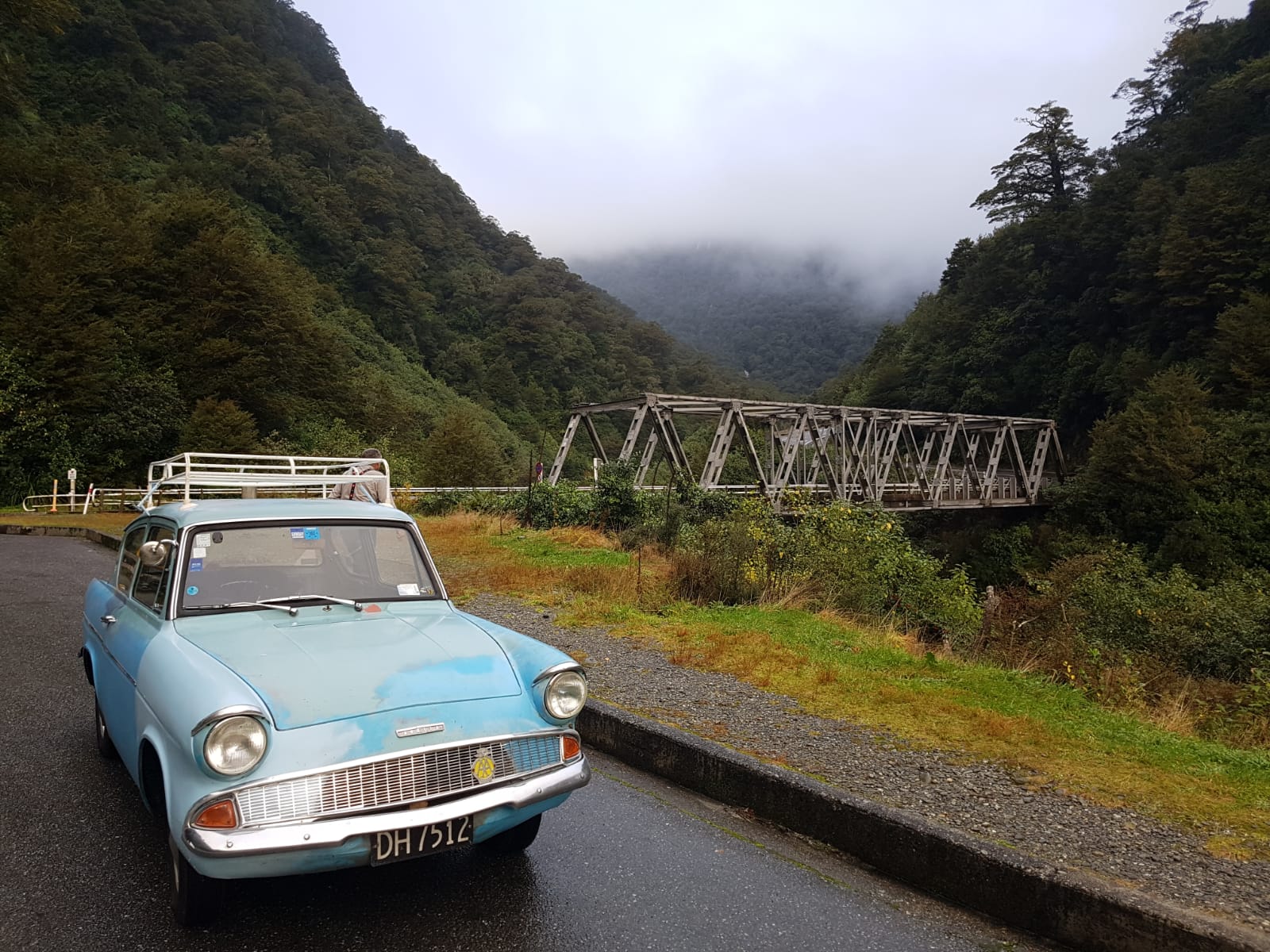
They've begun their trip north now. I think they are in Hokitika tonight. My dad said it hasn't lost a drop of engine oil so far. I call BS. He reckons someone wanted to buy it from him in Wanaka but died when he stated his asking price
1 point
-
sweet project vehicle. would look sweet with some low and some form of hand painted company signwriting of its era. also the lady at nzta who deals with the black plate stuff might be able to dig up some info on the van too otherwise fill out a ownership form. there is a specific one for deregistered cars and get a jp to sign it. and maybe get the all clear from police that there is no interest in it1 point
-
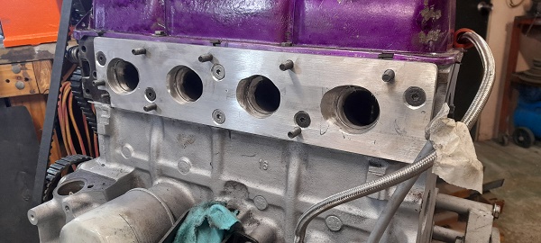
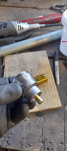
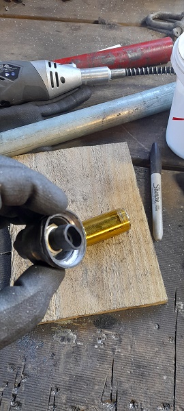
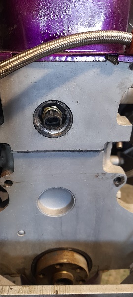
was thinking about temp sensor for the ecu and where to put it.. couldn't put iy in the factory position as the factory sensor was there for dash temp gauge.. thought about the hole in the head between #3 and #4 inlet port but there is no way with the linkages for the inlet manifold... so then i thought about the frost plug at the rea of the head...there is about 30mm from the rear of the head and the fire wall and when i popped the plug out and measured the depth i had ..that was 60mm from head surface to 34 cylinder wall...........and the temp sensor itself is 60mm long. soooo i garbed a new front plug....gutted it and got some thick pipe and cut that to size and then a washer.....welded it all up and fucking back.......sorted.. andits about 10mm of the cylinder wall. and as paranoid as i am with it leaking and being in a spot that the motor will have to come out if it does....i plasty dipped it twice. tapped it into place and it should be fine. also trimmed the adapter plate for factory temp sensor. .port matched it to the inlet manifold.. port matched the head to the adapter plate (will do for now ...this motor is to only get it all running..i don't have hope for it lasting long)..gave to surfaces some belt sander love ..some lock tight on the socket head screw.....a gasket and some extra sealant and bolted it on the last time .....(well till she epode's ) cheers
1 point
-
so... the painter told me he had a bit of an incident with my car. . . . . . . . . then he said he spilt a few litres of paint on it. . . . . super duper pleased with the result. .
1 point
-
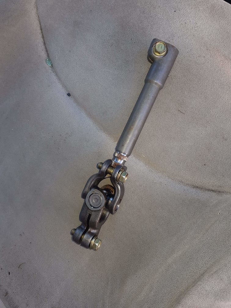
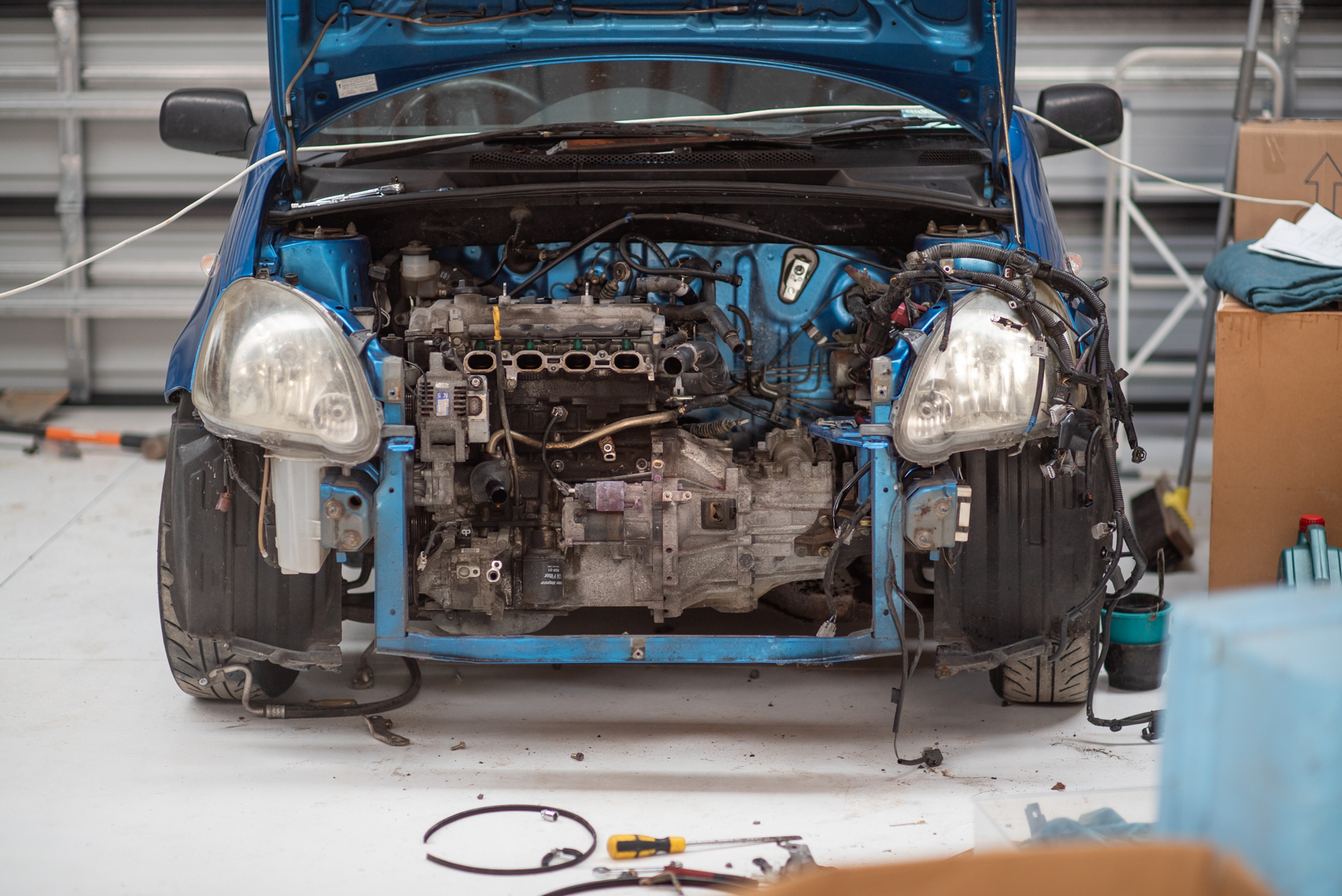
I got all of the bellhousing stuff sorted, got the manual rack in (I have to remember to do up bolts on the steering column...) Ends up losing about 5kg with the non PS rack and no pump. Then I got the engine mostly in but there's some weird shit going on with engine mounts on the engine side. (The other two are on the gearbox) The steel mount part on the Prius block is a different shape to the 2NZ one, so I cant swap them over. I am hoping this is because the Prius block uses a 1NZ specific mount that's different to 2NZ one, meaning I just need the different rubber mount and it'll work. But the mount is wanting to sit too far forward currently, by maybe 20-30mm. So it's not sitting in it's proper spot yet, but happy to have it in the engine bay at least. It's actually been pretty easy to work on, a sideways engine isnt nearly as shit as I remember from MR2 ownership. Also I think I damaged the clutch hose so might need to go find a replacement. More hurdles but still making good progress! I think I'm still hopefully on track for engine start on the weekend. To Do list for first fire up: -Sort engine mounts -2 longer bolts and nuts needed for bellhousing -fit starter motor and battery -fill gearbox oil -fill engine oil -Fit CV rack boots properly -fit radiator/hoses/add coolant -EWP wiring -fit intake and shitty exhaust manifold -Setup new base tune file for 1500cc and 2ZZ injectors.
1 point
-
Thread dredge, thanks to @a.craw4d. Ok, so not 1/24, though I did build some & have a couple unmade somewhere. Models is models though 1/35 WW2 stuff was my thing. I had a break from the glue fumes for 30+ years but have got back into it recently. Pics of a few out of the loft... This is chopped down from the longer wheelbase version. Scratchbuilt fuel tank and tyre rack. You can buy the SWB one nowadays. Burned out Opel Anyway, times have moved on and skills displayed on that internet inspired me to get back into it. First bash was this Flak Half-track. Rushed it a bit and didn't really have my eye/hand in but it is what it is. Some bits I'm very pleased with, others not so much. Current build is the last kit I started before I lost interest in about 1990. It's a Bergepanther ARV. I gave up when the rear track idlers kept breaking off so back in the box it went. I'm now using it to practice my weathering & rust, hopefully it will be a bit more subtle than the half-track. I may even end up finishing it. As it was... Repainted it later dark yellow and am now slowly working through ageing it and trying to make it look like metal. So that's enough stupid big post from me, I'll add pics as it goes along. Hopefully I won't be alone on here. Sat on my own, cementing bits of plastic together, waiting for the world to laugh and point, wishing I was a tank commander. Vroom, vroom.1 point
-
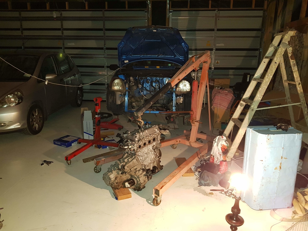
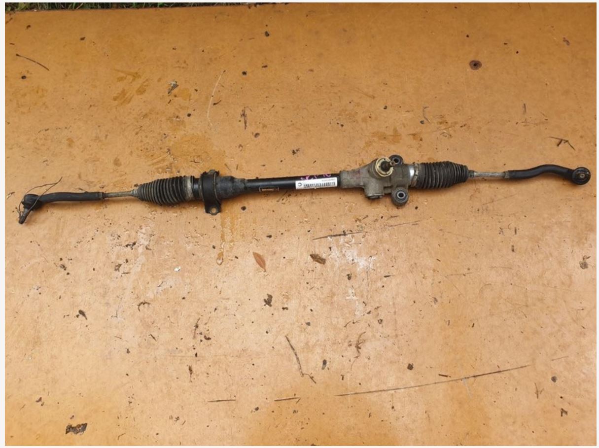
Okay so I managed to find a manual rack car at pick a part. All it cost was 50 swear words, catching hepatitis from crawling over busted glass and about 20 bucks. Not bad. (Also got the rubber boot that goes over it) my manual rack turned up in the post some time today as well so im good to go. Its a big dick punch working on anything in the vicinity of the power steer so im happy to be rid of it. Then ive just been burning the midnight oil taking this gearbox off and on about 20 times to confirm bolt hole stuff and make sure it all goes together nicely. I still need to file one of the holes a little more, then it will be about ready to chuck back in. Hopefully fire up on the weekend or earlier. Im glad the steering situation was easily resolved, because it was becoming disheartening to think getting the motor back in would see significant delays.
1 point
-
oh, hi!! so yea things have been great with this car. except the output bushing on the gearbox is flopping around and subsequently the output seal is leaking and flinging oil all over the exhaust. this is shit. the gearbox has only done a couple thousand Ks since it was brand new from Toyota. apparently this is fairly common on the new R154s which fucks me off even more. I've fucked around with changing the seal multiple times and all the other usual checks but it just keeps on leaking. cool. so to fix it i have to take the motor and box out because of the whole massive drive train/small car thing so out the motor comes. its fairly depressing taking a motor, that you have worked very hard on to make as new and shiny as you can, out of a car and seeing all the road grime and shit on it, as well as all the crap that goes everywhere when you start taking things apart. well, its what has to be done so away we go. not sure what else ill do while the motor is out. im not 100% happy with the clutch i put in it. its juddery and grabby at take off which sucks so that may change. fuck knows.............. anywho, first step, jack up your car. 2021-05-04_05-59-44 by sheepers, on Flickr1 point
-
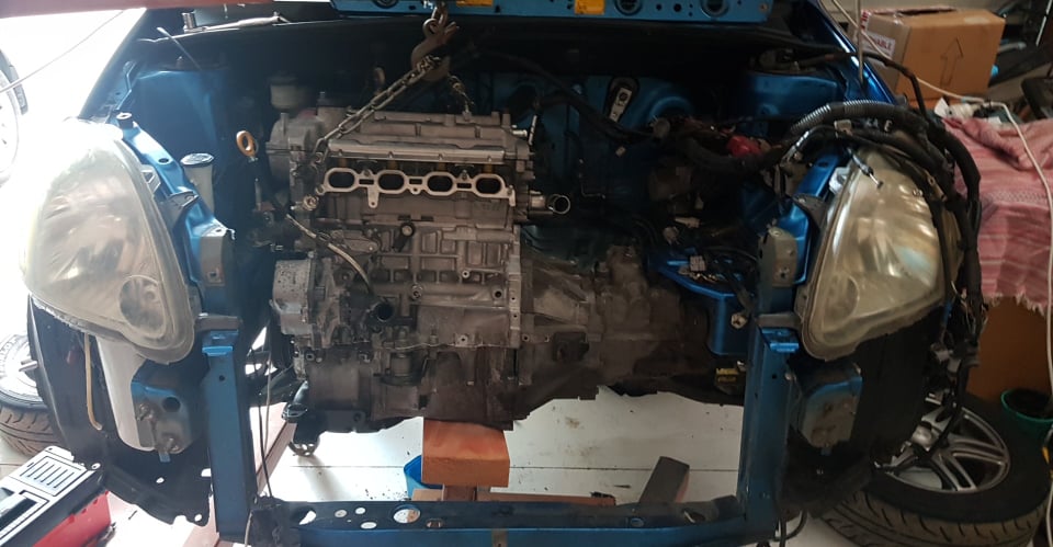
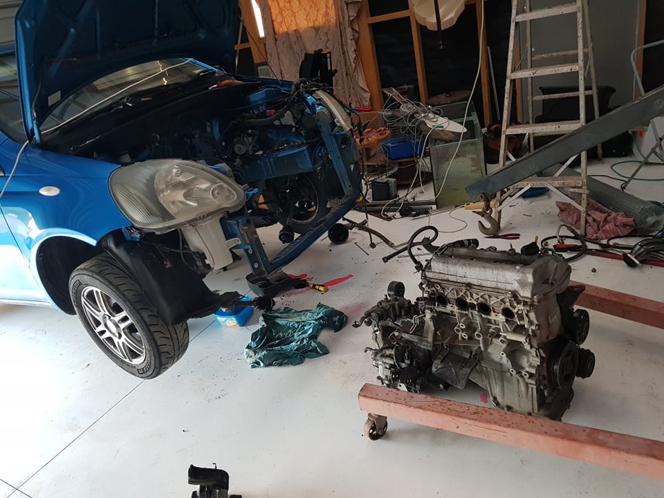
Big mission today to get old motor out and get the new motor/box/clutch/etc assembled. I was thinking it would likely be best/easiest to drop the motor out the bottom, like I've done with MR2 in the past. However once the axles are out it's pretty easy to turn the motor 90 deg and pull it straight out the front. Ended up spending about an hour and a half playing Dentist, when the new motor and new box both had the same alignment dowel stuck in them. Took a lot of heat and CRC and filing some flats into it before the bloody thing eventually came loose. Once that was sorted I tried aligning the box onto the motor but it was just too dark and too tired. So will get that sorted tomorrow after work. I CBF with the power steering so I've been keeping an eye out for a manual rack Echo at Pick a Part etc, but havent seen one yet. Then one just popped up on Trademe so bought it. hopefully it isnt missing a UJ or something specific to the manual rack (probably is, and I'm stupid for buying this) "
1 point
-
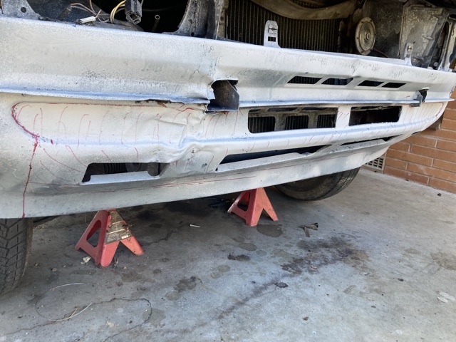
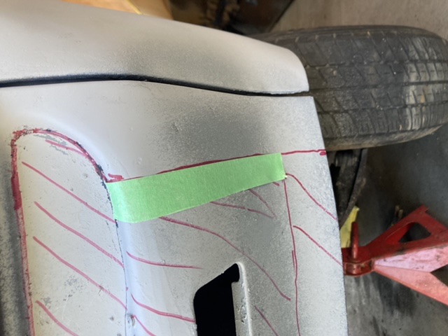
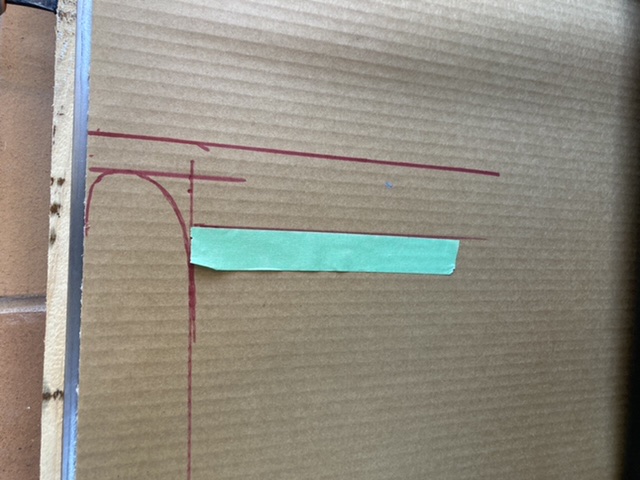
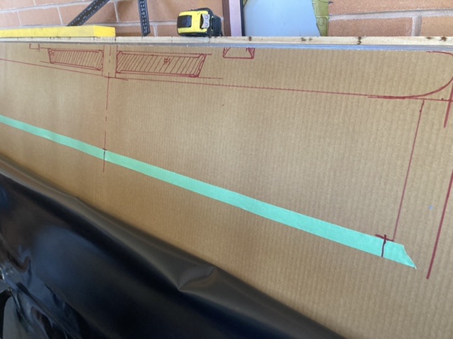
Templating the Valance. This is going to be hard! Might take a few goes I think.
1 point
-
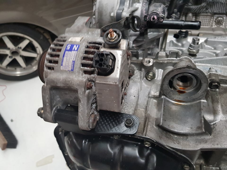
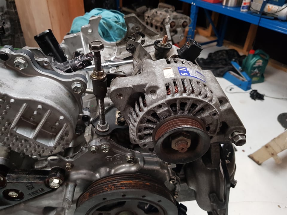
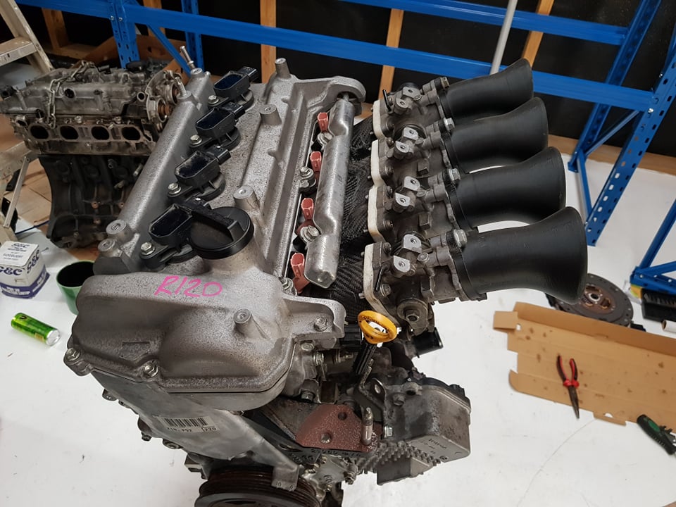
I've pulled the throttles off the car to mock up on here. Then reverted Echo to standard manifold which is a bit more WOF friendly, even if it's technically legal with throttles on currently. Also thanks to the excellent dude Matt Gill I've got some 2ZZ injectors on the way. So that's most of the puzzle pieces solved! The main task left to figure out has been the alternator bracket, which has resulted in some head scratching and a few different attempts at finding somewhere for it to sit. Settled on this, which is very low down bolting onto bottom of the sump. Ideally I didnt want to have the mounting points that far down the engine, but I think it'll be alright. Then the worlds shittiest assortment of accessories as a tensioner. I might improve on this, but if it works probably not haha. I dont have the skills or materials or tools to make a proper version of the bracket from aluminium, so I was hoping in someone in Waikato might be able to help? Here's some more specific details if anyone can.
1 point
-
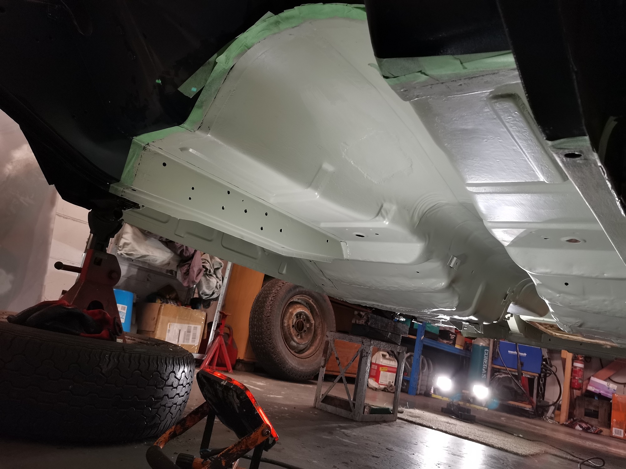
Finished removing the underseal. What a shit job, lying under the car scraping with a chisel. Only a bit of surface rust, cleaned up no worries with a strip disc and wire brush. Gave it a coat of Brunox, scuffed up with scotchbrite and brush painted with epoxy primer. Not mint, but good enough for the underside. Just need to move the stands and do the same for the jacking points now. Getting the fuel tank dipped and lined, rear brake cylinders sleeved at the moment. Next, I will tidy up and paint the diff and fuel tank.
1 point
-
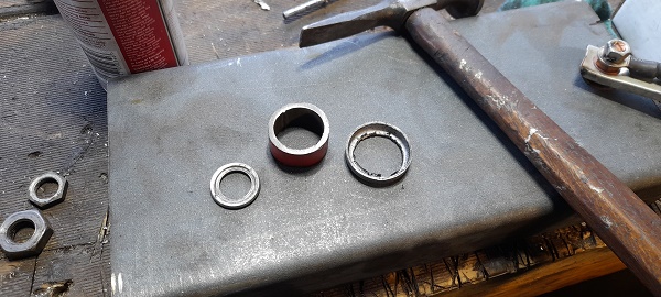
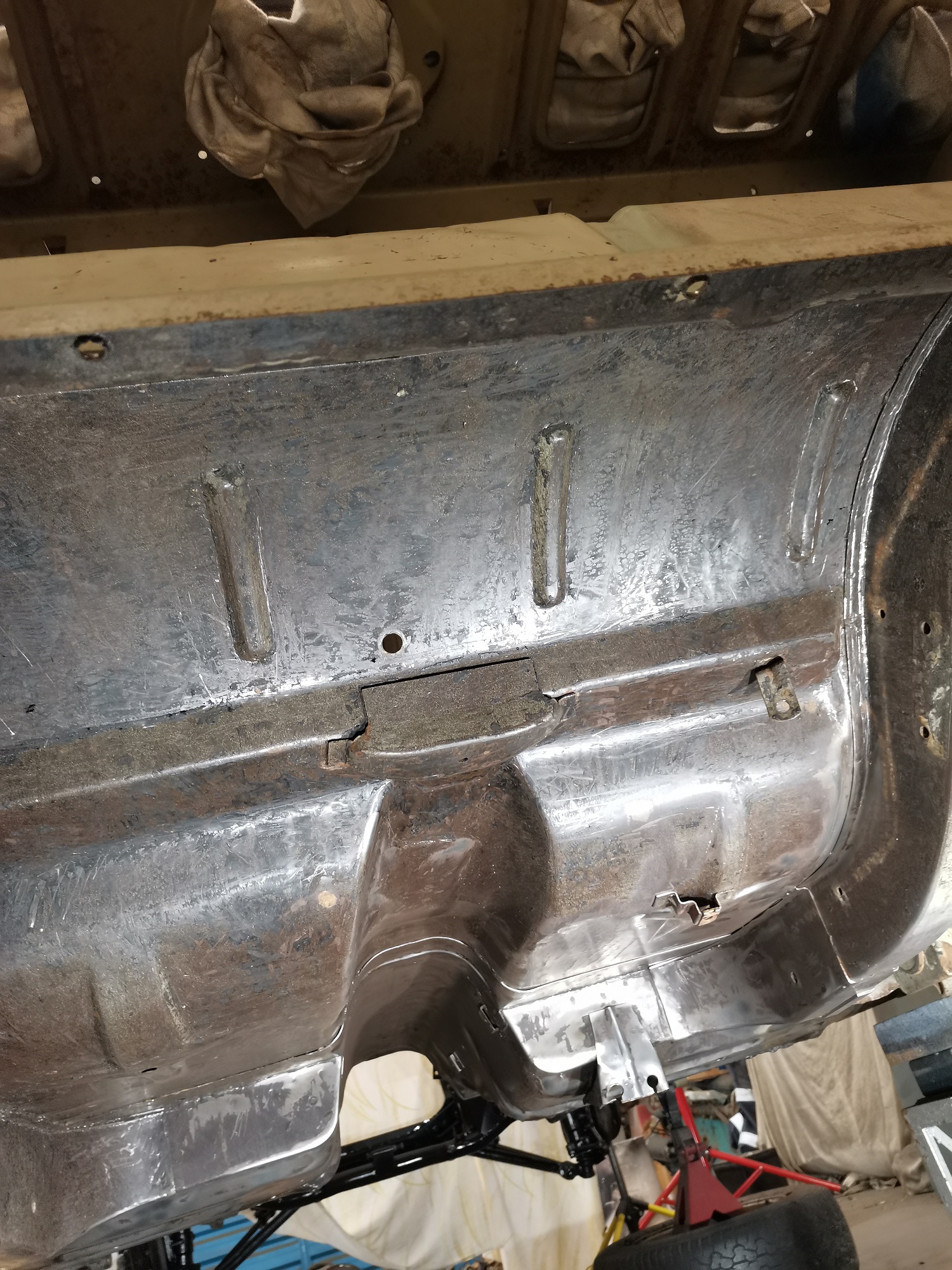
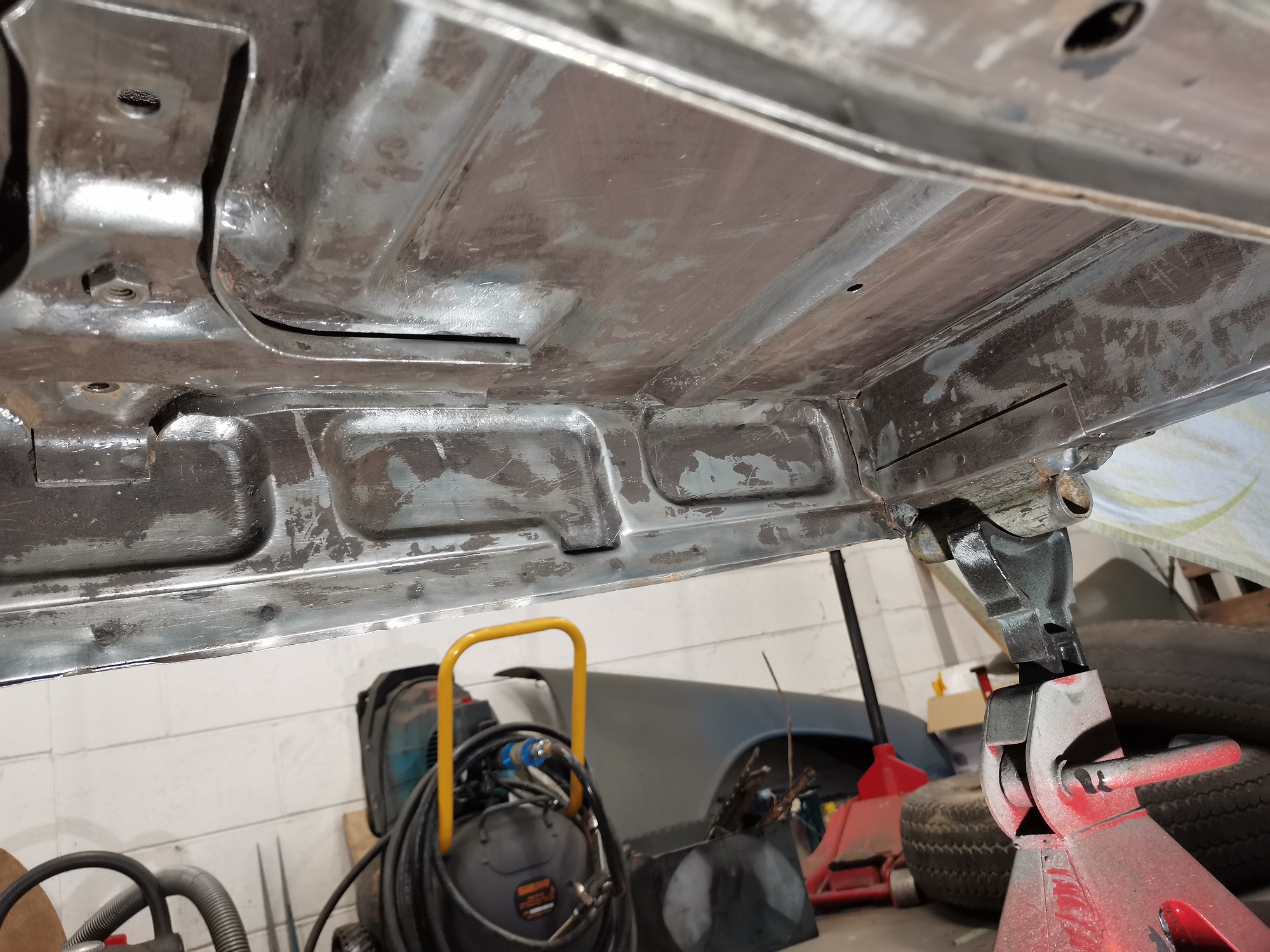
Hi. lets go back a few steps. I had just received my beam from Sean at kune re. I put a few layers of brunox on it and painted it black. and stashed it away. the next stage was to fill some holes and touch up some rusty peaces and i was waiting on a mate for a hand with this part but i ended up getting a bit impatient and smashing them out with the mig welder and cleaning them up with a grinder cause im clearly not a welder and while i was at it i went over a bunch of my old welding peaces and ground them up and cleaned them up. a few late nights and got the job done. next up i wanted to cover the underneath with brunox and get a few layers in to convert the small amount of surface rust it had and set a good base. with that done i went around and chucked a bunch of seem sealer on crap to clean it up and make sure aint no water getting passed my dodgy welding techniques. once that was done i dusted the under body with some underseal. end result was pretty much brand new. next job was to get the beam in the bus, i needed to put the steering arm and the torsion arms on. this also meant i needed to shorten my leaves to now match the narrowed beam. to have them narrowed i visited a mate who helped me cut them and he welded the ends together to make the leaves go into the ends easy. here we cut. here we weld then i kinda rounded the edges to help it find its own way into the hole and re drilled my locating hole for my arms to bolt into. next up the torsion and steering arm on the beam next job to put the beam in, and jesus i am lucky to have a hoist. me and @flyingbrick lowered the kombi down over the beam and bit by bit we went up and down with a peace of wood between the beam and the ground as the fitment was so bang on with my underseal on it she was binding up going in, definitely should have used lube. but we got there in the end beam in, the brakes went on the front, new rotors new bearings, new calipers, the only 2nd hand part here is the drop spindle and the retaining nut which was robbed of a bus rotting away. this wasnt an easy job. i ended up using a strop and tightening the bottom arm and kinda fitting the drop spindle in the middle now with that all done i installed my gear linkage. i replaced the bush at the front while it was out before i went and installed this next up was the rear. for some reason i was doing this all to fast and didnt really get many photos of assembly. but the new stepped spring plates are a breeze. actually after that i had to put the rear arms in, which i had replaced the bushes in quite some time ago and they were ready to go. so also installed them after the spring plates. next was the rear hub, i actually drilled my old one out to fit different bolts in for the horse shoes i tried to fit just before covid last year. so i got some second hand ones and headed to evans place to use his sand blaster and clean them up. before: note the long noes pliers as circlip pliers during after and new bearings fot the rear hub section. now with this all done i can put the axel in and put the rear brakes on and continue doing small jobs. next up was new brakes lines, hard and soft ones all the way through the bus. also my last slave cylinder was just left sitting out, kinda rusted and also never really worked correctly when installed on the bus. so got a new one of those but the cups where a different size than the last one, so got some small adapters to make it work also i had replaces both hand brake cables, accelerator cable, clutch cable and complete full axels and cv's some where along the line. This where i ended up in the last post. made it on the ground and drove it for the 1st time in over a year. Great success. one Greg for scale i just checked dates on this and i started grinding the under body and doing rust on the 12th of feb and she was on the ground out side on the 23rd of feb at 830pm.1 point
-
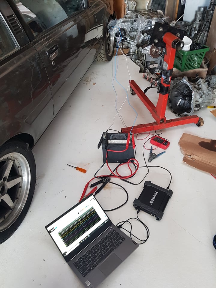
Figured out the EWP and got it working easy as. It's just 2 high current wires for 12v supply and earth. Then one is a pull to ground PWM signal to control pump speed. Then the other is a square wave pump speed signal which you can feed back to the ECU. (which is what I was hoping for) So you can tell if its jammed or stopped working before the motor overheats! Cool. It's got a failsafe so a high duty cycle on the pwm signal slows the pump down - So if there's no signal, it runs at full speed. Trying to work out the water line situation though, I'm not sure if there's a water bypass for if the thermostat is closed. What looks like a bypass hose also looks like a heater line. But if that's the case, no flow through heater core if the heater line is shut. There's also an extra heater sized water outlet on the exhaust side of the motor, which isnt there on the normal motor. Hmm. Might have to try find an engine manual that shows how it's supposed to go. Finally used my Aliexpress spec USB oscilloscope for something. I also got my head back from the engine shop with the new valve springs fitted, $75 saved me about 100 swear words and 10 hours so a good deal. Hopefully cams here on Monday.
1 point
-
Cheers man, pleased to be adding to my small collection of quirky patinavans with a 1:1 scale model
1 point
-
Well that was never coming out intact with the rubber. theres 2 distinct sheets of laminate with a gap in between which crunches and cracks. Also, there clips in the corners on both sides so you couldn’t get in to ‘flick’ the seal out. bit the bullet and sliced the seal. pretty happy! Hasn’t broken through anywhere, just scode and pitting. Even saved most of the trim clips. lovely piece of original paint Was good to access the top dash fasteners and swing the dash down for a look (cool design has whole dash pivot on two bolts in front of the doors) so I vacuumed more shit and dirt out. Allowed access to the wiper spindles too so I whipped them out as they are frozen. One came right, ones soaking. My lovely mrs sat and cleaned up the stainless trims with wire wool for me too!1 point
-
I had to pull the carb apart again when I got home, there were more little bits of glove past the jet. After cleaning the carb out thoroughly it runs a treat again. I filled the bowls with 91, and went for a quick hoon. I didn't detect any pinging - perhaps I can run it with 91 at the current ignition timing settings. I also spent the day fixing the heater core for it. The old one was disconnected, Glen reckoned the tap was leaking. I pulled it all out and found not only was the tap leaking, but the whole core was covered in corrosion from its own leaks. One of the tanks was leaking where it joins to the core and there were a few leaks in the core itself. I used a torch to melt the solder and remove the tank, I was greeted by an entirely blocked core - full of the foulest rust sludge you could imagine. I cleaned all of the tubes out using a brazing rod and a garden hose running at full power feeding the other tank. Afterwards I gave it all a good clean then reapplied solder to the tank and core mounting faces. I don't have any big clamps, so I just used some stainless lock wire to hold it all together while slowly moving around the tank to solder it together. This was followed by about 10 rounds of pressure testing and chasing the leaks around in the core itself. The tubes are all soldered together and in places the solder had cracked or corroded. Simply applying heat and solder to all of the tube seams was enough to fix them eventually. I had a random heater tap laying around, it does the job. I just unsoldered the old one and used a bit of hose to join the new one on. I also lubricated the fan shaft. The heater control cable is a bit short for the new heater so I will have to make one some time. Currently you have to reach under the dash to close the tap manually. Also, I'm not sure what the proper plumbing setup should be for these heaters. I just replaced the single hose between the intake manifold and the head with the heater circuit. Will this cause any issues with overheating if I close the tap? I still need to find a new duct for the drivers side defog vent, the existing one is too short. But other than that, the car gets uncomfortably warm inside if the heater fan is on now.
1 point
-
and filled the garage with a lot of dust and some other stuff too
1 point
-
its coming along. im just tidying up all the little things that need doing. ive got some generic belt line rubbers coming for it then i can put the door cards back on. the bumpers are away being chromed and ill get them back in a week or so. not sold on the black center caps and i have another set on order should be here middle of next month. i drove it up the road to get some milk and i fucking love driving this thing, its fucking slow but its cool to just cruze along in and i can see myself doing a bunch of Ks in this as soon as i tidy u the last few things. believe it or not its still got a warrant! 2021-03-18_07-56-27 by sheepers, on Flickr 2021-03-18_07-56-37 by sheepers, on Flickr 2021-03-18_07-56-45 by sheepers, on Flickr 2021-03-18_07-56-52 by sheepers, on Flickr 2021-03-18_07-56-58 by sheepers, on Flickr 2021-03-18_07-57-04 by sheepers, on Flickr1 point
-
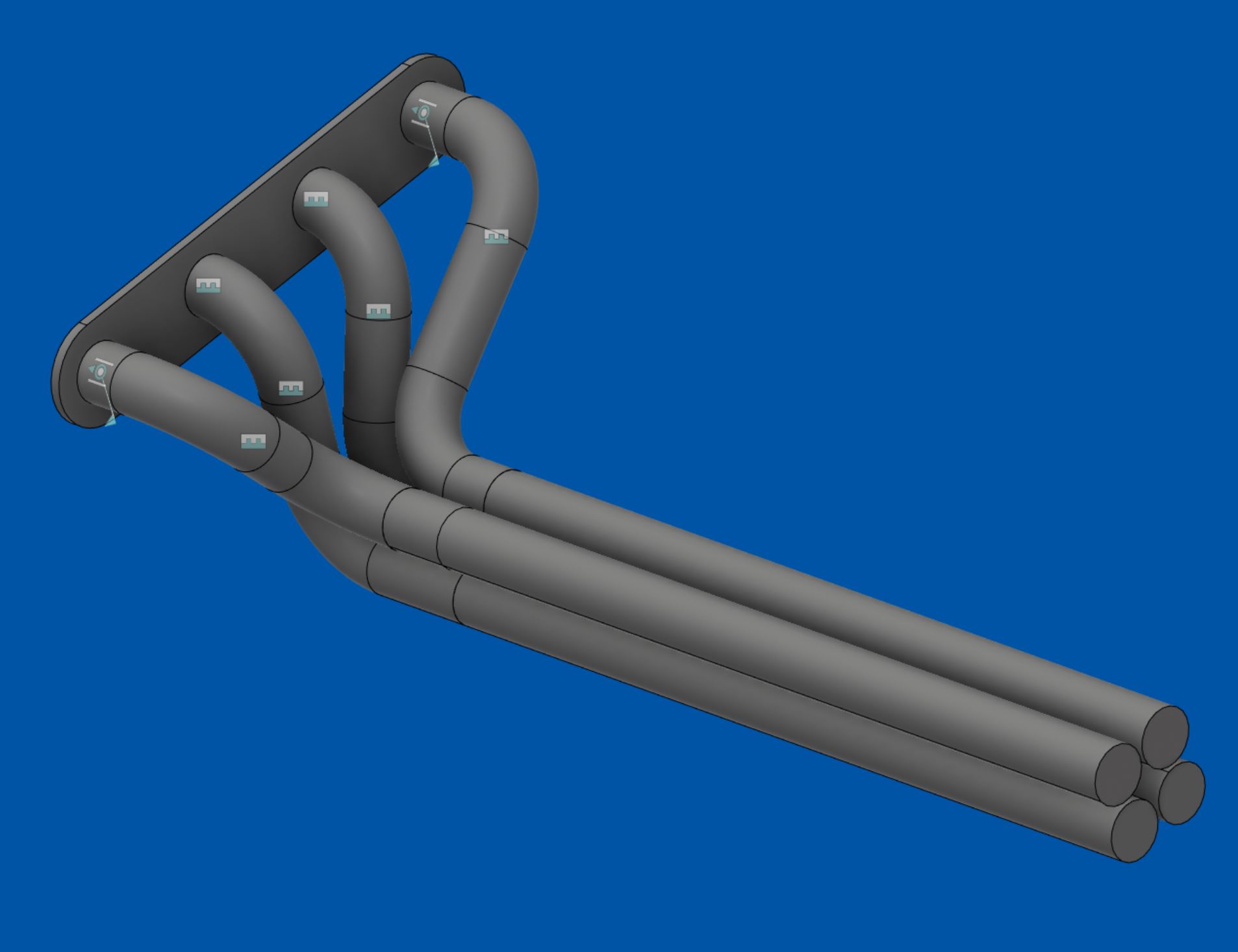
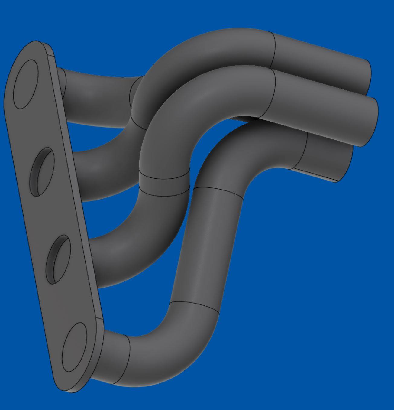
Boring update, which greatly contrasts to this very exciting car The model after my shape (NCP91) has a 1NZ motor that has roller rockers in the head. So this means they have way less lift on the cam because its multiplied by the rocker ratio. So it looks like they only have something like 4-5mm lift vs 9mm for the normal head cams. So what might be an interesting is put the low lift long duration prius cam from the non rocker engine (about 270deg duration, approx 4mm lift) into the rocker motor. Might be a super easy way to get some sweet duration and lift for cheap on the NCP91 Which should also have reflashable factory ECU. So might be quite easy to do some doorts in that shape car. But while thinking about all this, people said that the rocker head only comes on the Japanese new engines. And I realized the prius motor swap I'd seen, was someone from America. So thought I'd better check and make sure I didnt have the rockers. I didnt, phew. But I was blown away at how clean this thing is under there! I guess its a 50,000km engine on a hybrid where the motor only runs part of the time... so the real run time kms will be a little lower. Hopefully it doesnt have ring sealing issues like some of them did. As they have very low tension rings for less friction. Might be solvable by fitting a vacuum pump on the crank case so there's a higher pressure differential on top and bottom of the piston. Yet again, prius is basically a pure bred race motor, already setup with piston rings for dry sump. haha I have ordered a valve spring and titanium retainers kit for it. This cost more than the whole motor did, but will be worth it to see if I can stretch it to 8k rpm haha. Also, this motor has the exhaust manifold at the back of the head, and then the exhaust runs backwards obviously. So I've been revisiting the idea of trying to use cad to design an equal-ish length manifold thats made from as few parts as possible. If I could get away with having the pipes run perpendicular to the flange, backwards, I'd only need 2 90 deg bends per runner and they would be within about 50mm length from longest to shortest. Also noteworthy that this design has each runner sitting flat on its own 2d plane, so each runner could lay perfectly flat on a table. So you could print an A3 drawing of the outline and then cut the bits to shape and tack it together without any fiddly indexing of pipe angles etc. Trying to get them a bit more equal (within about 20mm) need some longer bends for the center two, but still only two bends per pipe. Would just need to be cut from 180 deg bends not 90s. So might be a good first project for an exhaust manifold when I learn how to weld one day. Or otherwise easy to just cut all the parts and have someone else weld it up. Not sure how to make an economical/easy collector though but will scratch my head a bit more and try figure something out.
1 point
-
So checking out new motor. Has water cooled egr valve and water cooled crank case vent tube. Guess they try do everything possible to stop knock or misfire with a big egr amount. Interesting stuff, that, can fuck right off. The electric waterpump arrangement looks easy to wire up, 4 pin plug with two big and two small wires. Will be 12v, earth, then i suspect pwm input and maybe a return signal or just voltage for pwm perhaps. It looks like it would be easy to retrofit a mechanical pump setup or vice versa. Id like to keep the ewp for nerdy reasons but i suspect mechanical is lighter and more reliable. It will come down to how tricky it id to mount an alternator I guess. As the belt arrangement might be better with the mechanical pump in place. As it gives more belt wrap and acts like an idler between aircon pump and alternator. The intake manifold is interesting with a tiny tiny e-throttle unit and a shit looking manifold. This too can GTFO obviously. The egr pipes are all in the intake manifold though which is good. Nothing intrusive in the head. This later motor has a flat response knock sensor so it wont max itself out by 5000rpm like the other one does. The main trickiness of this swap, apart from mounting an alternator. Looks to be figuring out the water lines and probably just blocking a bunch of it off. Will draw some shitty diagrams to compare to regular motor next time im up.
1 point
-
There's been a 2012 Toyota Aqua 1NZFXE engine on Trademe for $520 a while... 50,000km old, but says it doesnt include any extras just sold as bare block essentially. It's been relisted lots of times over, so I figured it might have been picked dry of parts since the pictures were taken. The only thing I really need that might have been taken was the water pump. But even if it wasnt there, still a decent price for a low km engine I guess. Since it was for sale from a wrecker near my work office in Auckland, I thought I'd pop my head in while I was up there yesterday and see what's left. I asked the guy if I could take a look at the motor, so we go over, and way down the back it's been sitting on a pallet completely untouched. Still has coilpacks, electric water pump, EGR junk, wiring loom, etc etc... and he said he'll include all that stuff if I buy it. Sweet! After some fairly one sided chats involving his enthusiasm to be rid of it, he haggled himself down to selling for $400 with no warranty. Done deal! So for now it's just going to be put in storage at my Dads place in Auckland until my shed is built. But I've already got the 1NZFE cams and sump ready to swap across, so will see if I can do that up there in the meantime. Gonna be good! Prius + echo combined, what an absolutely astounding motorsport pedigree1 point
-
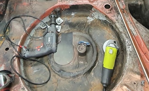
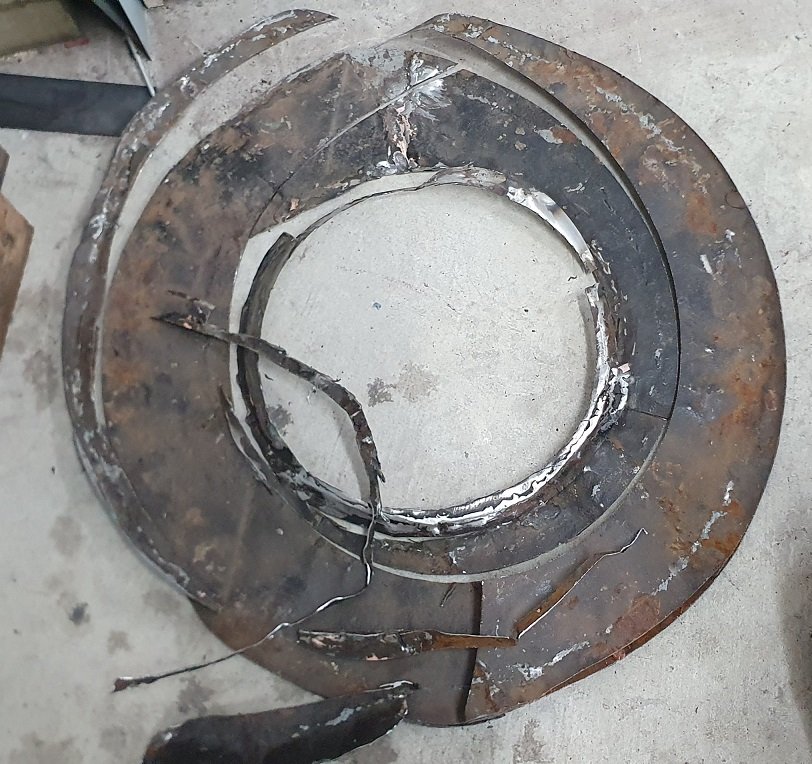
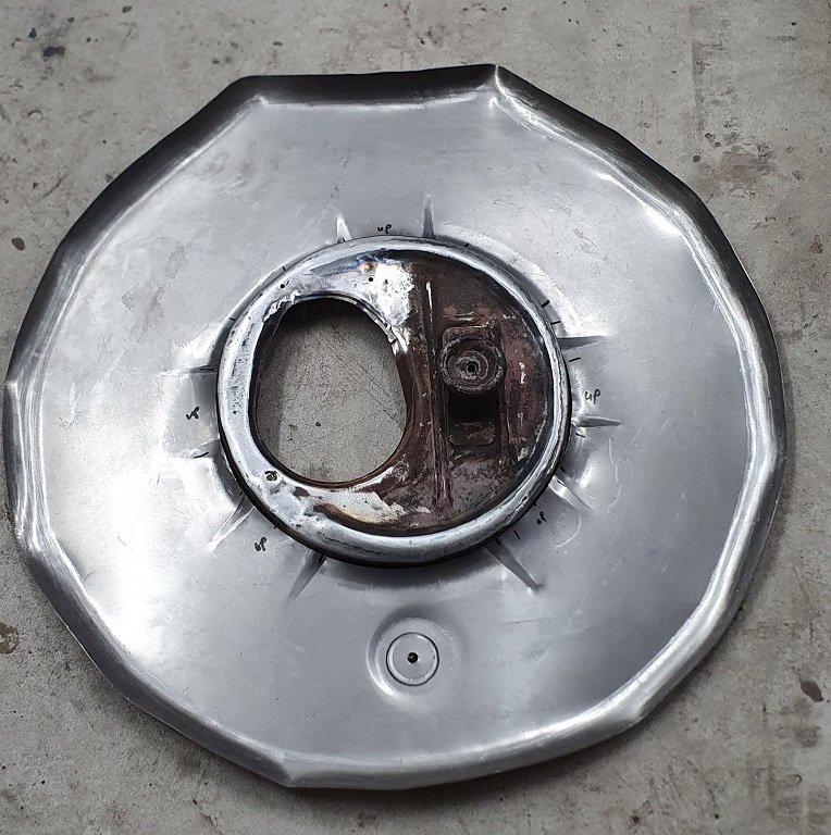
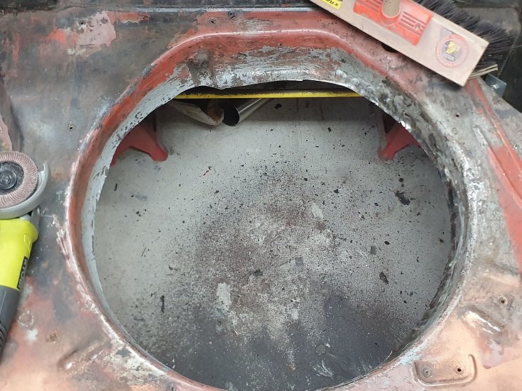
Spare wheel well! been a while in the making. It was looking like a sara lee danish dessert in there - layer upon layer upon layer upon layer... and bits chopped out etc etc. so choppy choppy Fixed up the middle part to look somewhat right and cut/pressed the stiffening and drain into a new bit. rolled the edges too welded the centre in and tested the cover Tacked in. welded and sanded Pretty happy with the result - way better than before.
1 point
-
Ooooh its been over two months since I updated this thread. I have not touched this engine since stashing all the bits under the bench out of harms way, throwing a blanket over the main block on the bench and spending most of my time since then buying up many Micras, working on the housetruck and building the mezzanine floor in the shed. Oh and some of that paid work thing too because we do have a mortgage to pay. However - I still have a little bit of progress up my sleeve to report before we get up to real time. So I can do an update and hopefully soon I'll be back into working on the engine. I'm very much looking forward to moving in upstairs because I can whittle away on the project even easier. Well at least I think it'll work out like that? There's still a load of sawdust to create yet before we can move in though. So where I left off last time was in making the start of the adaptor plate/engine side of the bellhousing. I needed a flywheel to work out its depth, due in part because I am intending on using a concentric slave cylinder, one that was left over from the Ford Mundano that we had robbed ages ago for its engine to fit into the Viva wagon. I had a Subaru Leone 1800 ring gear to suit the gearbox. I needed a clutch setup to suit and started hunting a variety of places. I found a brand new subaru Leone clutch disc going cheap on trade me so I snapped that up pronto. Now a suitable pressure plate. I was just going to buy a Subaru item but had realised that it wouldn't have worked - hence my question to you all in the last update - but no one on here came forward. Someone on retro rides forum won the prize though and guessed the issue. Whilst out on a run, my head clear and thinking of things it suddenly dawned on me that the pressure plate tension straps would now be in compression due to the Hondas anti-clockwise rotation (or clockwise when looking at the pressure plate). Luckily there's loads of clutch components available for early Hondas with their anti clockwise engines and I ended up sourcing a new pressure plate from a mid 80s Honda accord/prelude that would fit the bill and suited the new subaru leone clutch disc I'd already bought. The pressure plate was cheap from Rockauto - turning up only 5 days after ordering. They always amaze me! Clutch sorted and sitting on the bench. I could now measure up and start on a flywheel. I had Dylan @ThePog draw up a cad file of what I wanted- the right diameter and pilot holes for the adaptor bolts. He suggested that I get them to leaser cut pilot holes for the pressure plate bolts while at it and this saved some time. Got my plate cut and picked it up from Dylan's - giving me another chance to marvel at his Dynafari. I first set it up and bored it out a 1/4 way through to fit perfectly onto my flywheel hub I had previously made (this hub also has the surface that the rear main seal run against)... I could then seat the flywheel onto the hub, clamp them down and drill right through into the hub. Drill out to tapping size, tap the hub holes, clearance the flywheel holes and finally countersink and spot face the flywheel holes to suit some fancy bolts I bought - these need to sit near flush with the flywheel surface to clear the clutch disc damper springs. Pics... Flywheel now bolted to its hub I set it up in the lathe for machining... Then gave it a skim. Checked it again, double checked it and then triple checked it. All good. I then machined the required step onto the face to suit the factory specs for the clutch. Next thing was to add the ring gear I add. Now this was a bit tricky because my lovely old Mitutoyo vernier calipers (one of the first tools I bought when starting my apprenticeship) were not big enough to measure that diameter. My old work place I did my time at had some lovely 600mm Mitutoyo calipers in a lovely wooden case. They were one of the treasured items of the tool room and I used to love using them. I had priced up some 600mm items from a variety of other brands but wayyyyy too expensive for me. I'll still keep looking because they'd be handy for many jobs. Might find some second hand. But that didn't help me when I wanted to do this flywheel now So I made an extension from some stainless I tigged together, replicating the end of my calipers. Taped in place securely and hey presto- I had a new updated tool. Never perfect like the real thing so I had to really triple check my measurements but managed to turn the flywheel down to give me just the right amount of interference fit I wanted from a shrink fit. Into the bench top oven the ring gear went, heated up and it dropped on to my machined step nicely. Cooled down and its not going anywhere. With that in place I rechecked it all and got the throw out on the flywheel down to about 3 or 4 thou. Super happy with that. My clutch kit now bolted on in place and I have something I can set my bellhousing depth to suit... I have added the required dowels and its all done. I'll get the flywheel, clutch and crank balanced together before assembly of the engine. So that will be the next update I think. Machining the spacers that will become part of the engine side of the bellhousing adaptor. Then I need to finish off making some chain tensioners to suit the oil pump drive chains. However I still have plenty of other jobs to do on the housetruck and the mezzanine. Those are a priority whereas this is just a fun little project. But I must mention that today whilst out on a bicycle ride we had about 50 various motorbikes pass us on part of a charity run. I spotted a bright metallic blue Goldwing 1500 go past and as it accelerated up the hill we were on it had that distinctive flat six exhaust note and just sounded superb! It certainly got me tingling and all I thought of was that sound coming from my Imp A good incentive!1 point
-
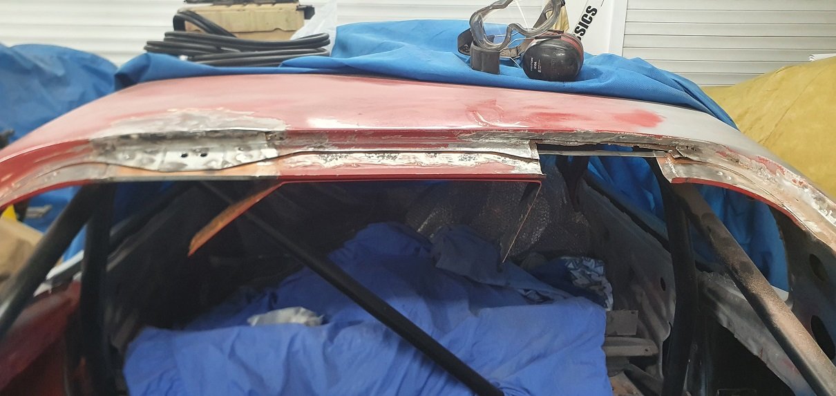
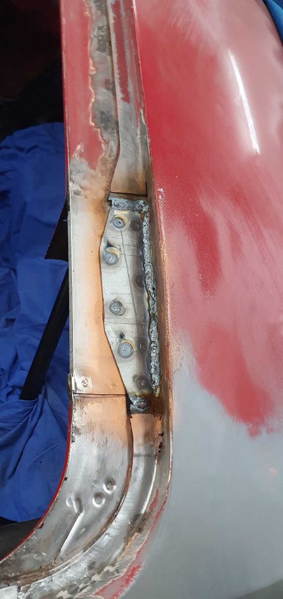
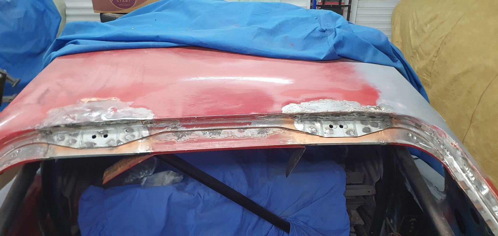
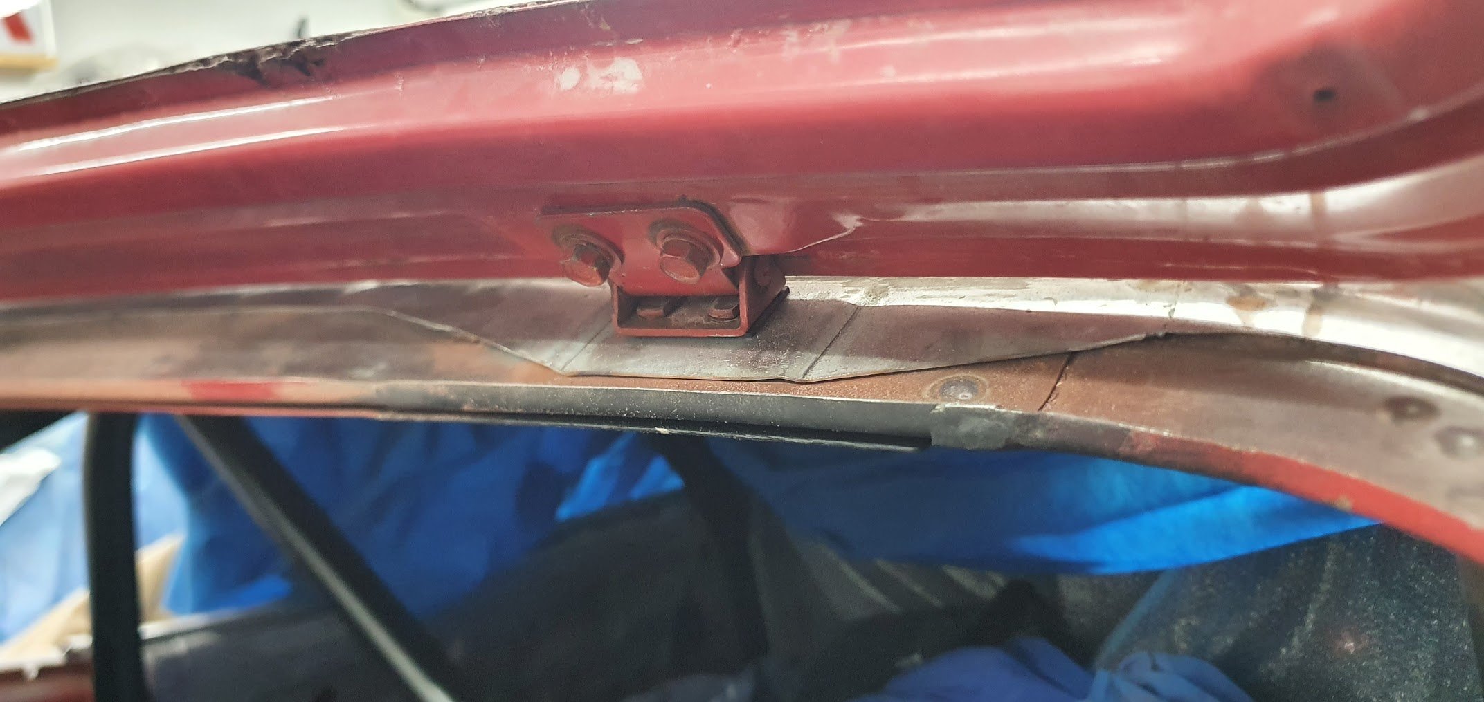
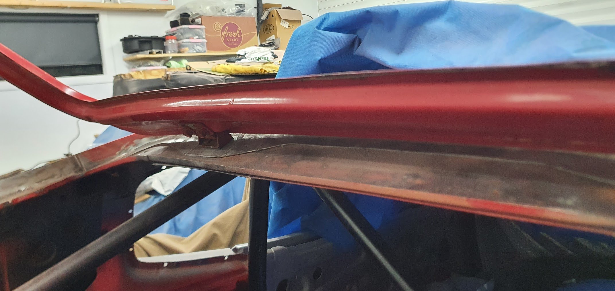
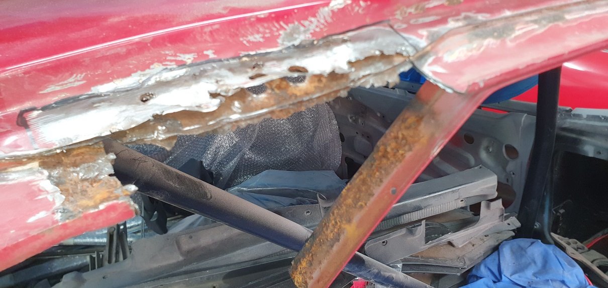
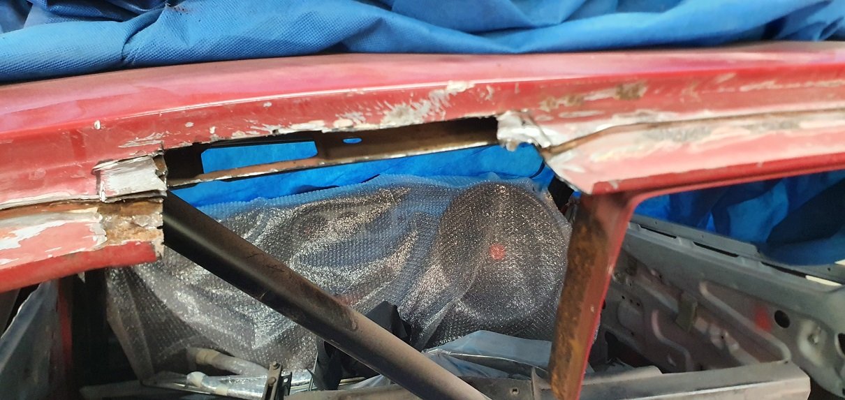
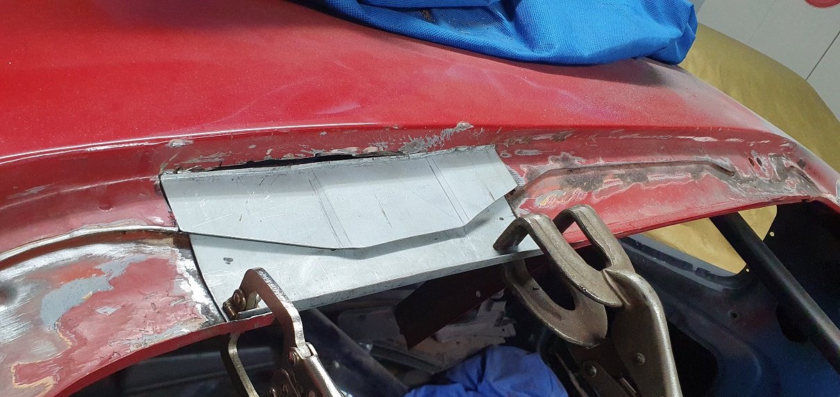
And a notorious part that rots from the inside out on these - the hatch hinge point - 3 layers of sandwiched rust
1 point
-
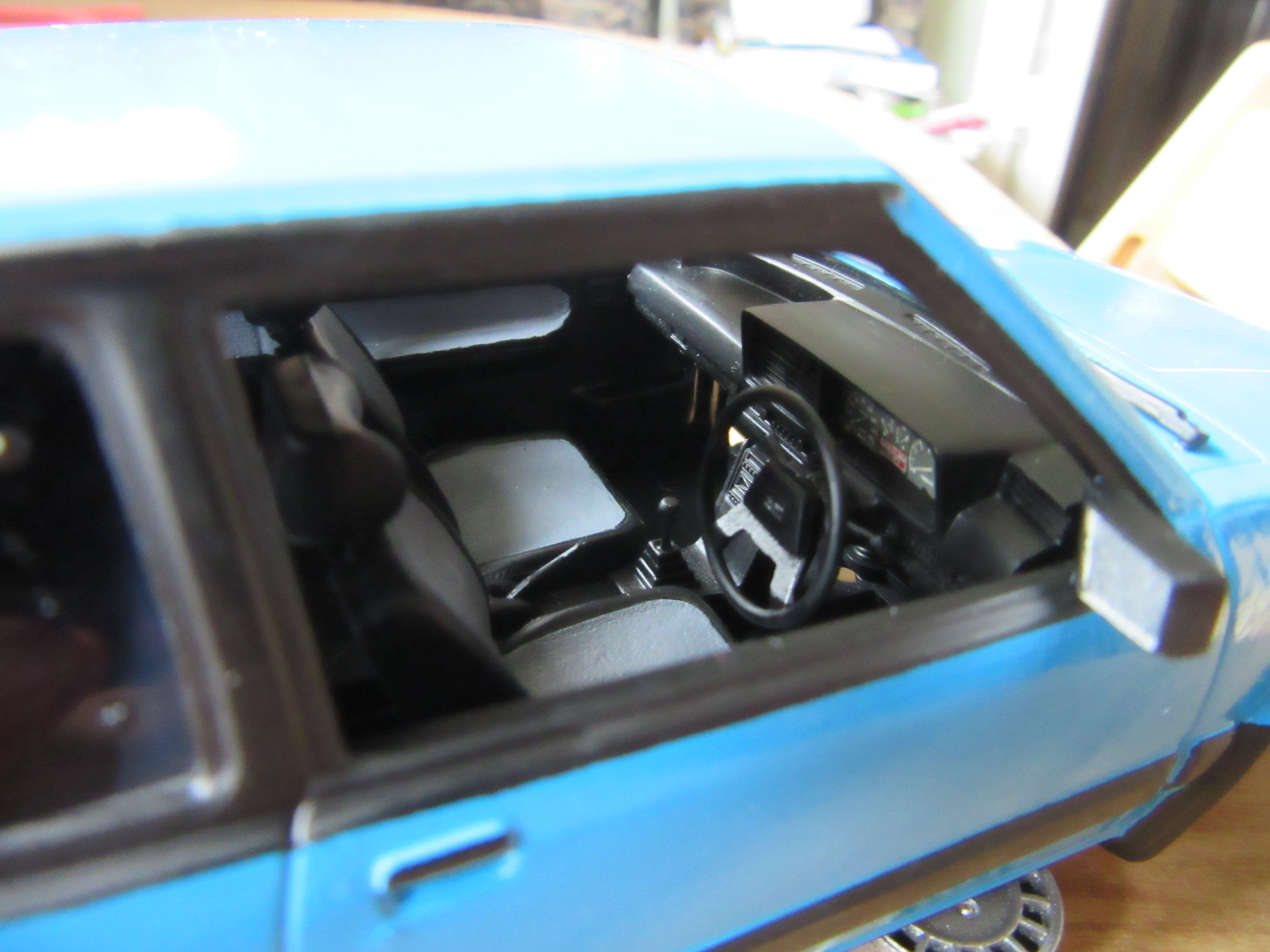
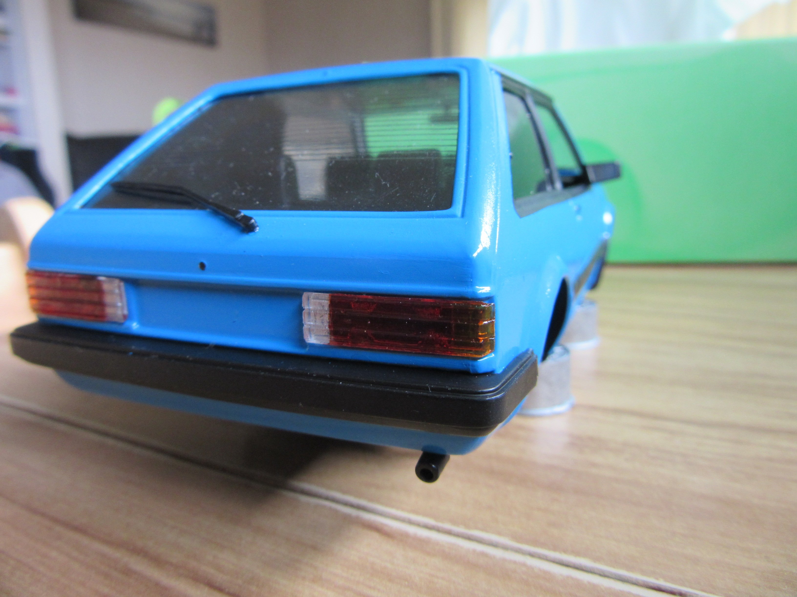
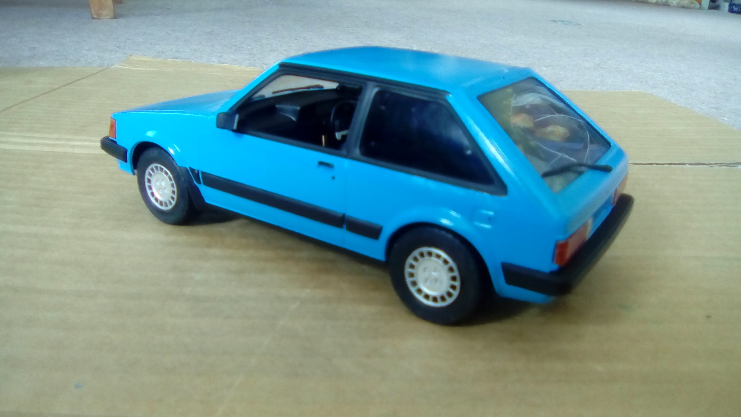
This is my first 1:24 car model I've just done recently. No mods, just a copy of the wife's first car.
1 point


.jpg.2c3492693f786143c1820d132a7275ab.jpg)
.jpg.74f74e0b06892d5a5a9022a53ed4170a.jpg)
.jpg.9b4e4f5a2a91f5f4c81babcd06be6c27.jpg)
.jpg.0e6a4298a464a5498127fe6e03e1a699.jpg)


This leaderboard is set to Auckland/GMT+12:00