
Leaderboard


Popular Content
Showing content with the highest reputation on 07/17/15 in all areas
-
I post this from the 2:30am ferry sailing, on the way home to ChCh from Wellington, because to be honest, I've had worse results from a night away from home:
 23 points
 -
Knuckle Draggers pic by Richard Opie, on Flickr Thomas (aka The Knuckle Draggers) did this for me. I giggle every time I look at it. It's arriving in it's original, A3 format soon.19 points
-
heres some more of it bolted to the superdupercharger. Untitled by sheepers, on Flickr Untitled by sheepers, on Flickr Untitled by sheepers, on Flickr12 points
-
http://www.machineofmayhem.com/box-house-part-4/10 points
-
Untitled by sheepers, on Flickr8 points
-
Soooooo with my airbox intake thingy. All is well and good, but when the motor gets to 6000rpm, datalogs show that there is a 3kpa pressure drop at the inlet manifold all the way to 8000rpm. How much is 3kpa? About 0.4psi which doesnt sound huge, but when you're working with 14.7psi atmospheric pressure that's about 3% of air (and power?) being lost before it can even get a chance to get to the throttle body. 3% of 200hp is 6hp so wouldnt complain about a 'free' gain of half that much if I could halve the pressure drop. So my first thought was, why not go from the current 3" pipe to maybe 4". But then I thought, since I no longer have a MAF, why have any pipe size at all? I could have a bellmouth straight on the throttle body for max flow. Then have a big enclosure to feed it filtered air with minimal pressure drop. This would take up a lot more space than a normal intake though, So the first things first is see if it seems feasible for space. I took a photo of the motor as straight on as I could (If wanting to do this, stand back far and zoom in, to minimise perspective distortion) and drew a rough sketch in Cad to see if theres' about enough space for a bellmouth, some space around it and a panel filter. Seemed okay so I plonked the motor back in and started on some CAD (Cardboard Aided Design) to see how much space I've got: Then roughed something together in cardboard, this is the Rapid Brototyping stage: Then copied the dimensions to CAD: Then made version 2.0: Back to CAD, made it more roundy looking: Then started working on the second half of the airbox. So now I've got a pretty good idea of the maximum available area I can work with to make it any size smaller than this. (It's pretty big and gumby at the moment) At this point, I've got two options - I can keep the intake getting air from the big hole through the wheel well area and down to the front as per previous. Orrrr, there's a 91mm dia hole behind the headlight, I could get air from here and/or here: So time to head to Solidworks and try some stuff in the flow bench thingy. TWO INTAKE ENTER. ONE INTAKE LEAVE. I've set the airbox opening to be a source of atmospheric pressure air. And the throttle body area drawing in 170 grams/sec of air (As per datalogging from a few pages ago...) When I keep the airbox diameter really large, even with shitty bends. It keeps the pressure at 101kpa right to the bellmouth. (This graph shows velocity instead of pressure, but you will just have to take my word for it.) When I try a different (simpler/smaller) design that sucks are through the 91mm entrance hole in the front panel of the car... I lose 0.2kpa straight away. Which isnt much, but it just points towards the idea that bigger is better for everything pre throttle body. (Red is good, yellow is not so good, green is less good, and so on. Read the scale damnit) For experiment's sake I thought I'd see what happens when I run the "Big" airbox entrance on an airbox that's 10 meters long. Despite what you'd think it still stays 101kpa across the whole thing, right to the bellmouth. So it seems to indicate that the length of intake means bugger all compared to diameter. Even throwing some harsh 90 degree bends in there, the cross sectional area is so huge compared to the throttle body that there's effectively zero pressure drop. Aaannnnnnnnnddddd that's as far as I've gotten. But the plan from here is to make a cardboard model of the exact shape that I'd expect to build it. Then put it into CAD, then I've got the options of getting bits lasercut or whatever, to minimise the odds of cutting a finger off trying to build something properly. This whole thing might be a big waste of time and acheive nothing at all, but it's helping keep me sane through winter so that's always a good thing. But, I'm pretty confident in my ability to quantify a change for better or worse now. So even if it's a failure it's a win, because Coupe Life8 points
-
Some progress....6 points
-
Look whats in the bay Pretty stoked to finally get this thing fitted, its snug as hell but looks good. X-Flow out Gearbox lines up with the hole, will need to cut the original mounts out of the tunnel to get it to fit but looks like it will be tight. Might have to change the tail housing to one from the courier box as its flatter. Ready to go... Cheers to Chris aka Low N Slow for the mounts, wiring and Link, and the adjustable cam gears. Will further fit the gearbox and clean up the engine bay more when im back home, things are looking up!6 points
-
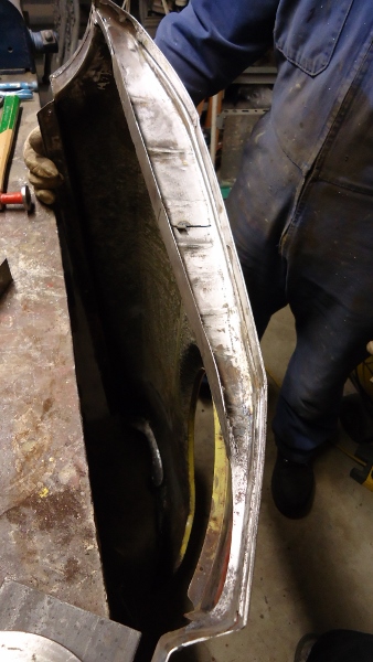
I was going to steam some strips of pine to bend around the cockpit cut out for reinforcment but on a test piece the MDF turned to soup when the wet wood went near it. (Im hoping the fiberglass will weather proof it enough.) So I just cut it up into a bazilion bits to follow the contour, It added a suprising amount of rigidity. I cut the bonnet out and added a bit more stiffness to this too. I started making the pedal box today, it goes beside the engine.5 points
-
I'm in, and yet again I'm rolling Japanese, in a mint Cordia this time tho!!!3 points
-
3 points
-
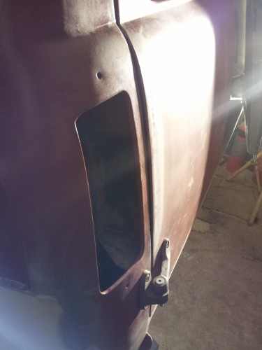
More work on aligning panels. Ended up making a new inner wing piece on the drivers guard that hugs the pillar. Have finally got it to a point i'm happy with where its parallel to the pillar and lines up very well with the door. No too many photos but lots of tweaking going on.
3 points
-
I have been dreading cutting the cockpit out... I only have one chance at getting it right.... I'm happy enough with it. I drew about 20 different lines before cutting this one.3 points
-
Hey guys, So I picked up this MK2 Diesel several months ago. The specs. - 3 Door, no sunroof. - 1.6 Litre Diesel manual - 240,000km on the body. - The body itself is pretty mint, but the paint is shit The existing motor is pretty well shot now. It looks as thou someone has rolled paint on the roof and bonnet at some point in its life. So the crux of this little fix up is Make her a bit tidier, faster etc. Low Milage 1.9TDI Engine from a 2003 Golf TDI 5 Speed Transmission Quaife Limited Slip Differential. Wide track suspension with 5 Stud conversion Bigger brakes Coilovers etc Work starts tomorrow. Although today I did strip the gearbox down this afternoon and install the LSD so that worked out good. The engine bay as it is currently.2 points
-
So I have finally decided to document my twin rotor Wankel engine project. Years ago I saw the video below of the twin O.S. Wankel engined R/C tractor pull car and thought that was the coolest thing since sliced bread. Fast forward a few years and I saw a twin rotor O.S. Wankel based engine in the YouTube thread, which has been the crux of this project. The engine build by ‘20B’ combined two O.S. Wankel PI’s together with a custom machined centre and rear housing, in addition to an oil hardened 4140 eccentric shaft. Unfortunately the only video of it running is the one below and the project thread stagnated years ago due to a crushed bearing. It wasn’t the only twin rotor project, as avid model engine collector Miguel de Rancougne had another O.S. Wankel PI based engine in his possession as seen below in a Christies auction handbook. http://www.christies.com/lotfinder/lot/a-twin-rotor-wankel-engine-4223480-details.aspx?intObjectID=4223480 Both 20B’s and Miguel de Rancougne’s twin rotor miniature Wankel engines provided enough reason for me to attempt to make one myself. So in March 2014 I purchased a brand new O.S. Wankel PII with the aim to build a two rotor with my friend Ben who happened to purchase a used PII from rotary mad Puerto Rico. The idea was that we would test run both engines then pull apart his engine and CAD model it. The parts required would be additively manufactured on the universities recently acquired selective laser melting machine prior to sanding smooth. To test this theory a single rotor and eccentric shaft were manufactured from a CAD model off GrabCad in AlSi10Mg aluminium alloy. With the surface finish of the parts worse than predicted and lack of a ferrous metal powder for the machine I decided to focus on building the test table for the engines.2 points
-
Mixing it up.2 points
-
And they work! I've also finished wiring the fans in properly with a real switch so I don't have to lift the bonnet when I get stuck in traffic.2 points
-
good meet, and go0od meat well done roder2 points
-
Am in Auckland... the Y has made it from the Wairarapa. Sweet ok A series. Datsun all loaded up with parts2 points
-
Boiler done, starting the rebuild process now. before and after.2 points
-
Stripping down the Group Heads while I'm finishing off the boiler and pipe cleanup. By far it's the most complicated part of the machine and a lot more needs to be done than people realise. Most tend to think that servicing the group head is replacing the shower screen and head seal with new ones, like those on the bottom right of the picture. It it's done properly then all of the components on the bottom half of the pic. need replacing along with a couple more seals I haven't stripped out yet, sometimes springs need replacing as well and occasionally the jet housing (tall bit between the 2 springs). All this needs a good soak in hot cleaner and then I'll start rebuilding the group heads.2 points
-
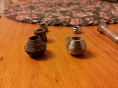
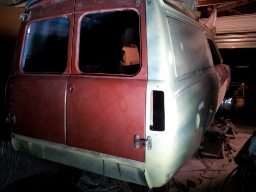
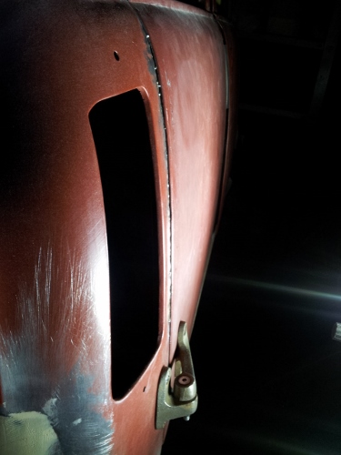
Lots of shaping, guide coating and sanding. Nothing too photo worthy but heaps of hours going in. Had a mate make up some new front door pins and rear door ball joint type insides for the hinges. No more play in the hinges, holds the doors in place a whole lot better. Old vs New Aligned the rear doors with the new hinges. Pretty happy with all the work to the doors. Still more to do underneath them. Heard you like gap. I don't so i cut along the edge, opened it up slightly to match the door and tack welded it for now. Will continue working on the rear doors and then start aligning the drivers door, guard and bonnet.
2 points
-
A few months go by and I finally get pissed off enough with my kitchen. Mainly the cupboards. Pictures describe my problems with them. So out they came. Before: My sweet oven After: My sweeter oven As we removed them, we were forced into either keeping the louvred window or blocking it. Now since I'm lazy as fleck but enjoy a challenge (conflicting, right?) i decided to have a go at framing a window. I hate working with wood. You can just 'build it up with the welder' if you cut it short or on the piss. But it came out mint. Straight enough for me. Replaced a few of the tongue and groove boards too since Mr Bora Beetle made refuge in them.2 points
-
Update ! Haven't had time to update in awhile . But here's a hint of things to come "Best of the best"1 point
-
looks very similar to the cb kit that I use ( http://www.cbperformance.com/ProductDetails.asp?ProductCode=7301T ) though I am only carb'd (fuel injection one day though)1 point
-
Team Ribs all in a row. 5kg up in ya. Good times. Thanks Rog for organising. Thanks Shaz for the transport too. Lovely to see you all. (jenga photo please)1 point
-
I'll get a 4age if Sentra Dave gets a 3SGTE.1 point
-
All this flash calcumalationaries going on - pretty sweet! Just get a 4age...1 point
-
Just a few little things after work today. Started to weed thru the Sticky cluster fuck of Modern car loom, thankfully only about 1/10th of that will remain after I am done with it Also degreased the replacement subframes and sprayed over with some engine enamel for a quick tidy up. Stripped the brakes off and dropped them in a tub of Phosphoric acid so that they can be painted tomorrow. - Also ordered my Adjustable Coil-overs today - 22mm Master Cylinder. - New headlights. - New handbrake cables.1 point
-
yeah you can make a new one, but it has to be 1 piece with no welds etc, even if its mild steel1 point
-
woah negative nelly1 point
-
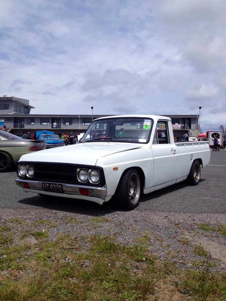
Well they're on the ute now. Leaves will be out in the weekend to be reset, it desperately needs some low! The front wheels poke out a little. Im not really sure what my best option is here, theres no room to move the center for more + offset, and im not keen to run those rubber universal fender extenders. Option #1 - Roll the shit out of them? The bodys already dented a rusty so could definitely pull off a rough guard look Option #2 - Some wide flares of another truck that will suit the later model guards? Option #3 - ??????? Give me your guard thoughts! http://oldschool.co....gos-b1600-yarn/1 point
-
Small post. Painted few things at work Also I think tom likes my car1 point
-
That noise :'( Those camber plates :'(1 point
-
Hey guys, Meet at the ferguson street lower plaza carpark at 7pm (the ashley street/farmers side can't happen unfortunately) meet us there at 7, then we'll grab some takeaway feeds at 7:30-8 from surrounding places. - Just a note, feel free to invite other cars/people along, but you will be responsible for them! Please leave no rubbish and no skids/rowdy driving in the carpark - We've been given permission from the Plaza to use this, and we don't want to loose it. We have a rain free car park, and the barrier arms go up shortly after we arrive, meaning no parking fees. This won't be on facebook as such, so make sure you write it in your diaries/phones. Make sure you bring some warm clothes and a camera. Seeya there!1 point
-
Carrying on from yesterday there are a couple of other things that I forgot to mention, the angle of the stub axle relative to the strut body is greater on the MK2 as it is on the Anglia (which is why you get the positive camber when you bolt it up, the fact that the tca's are longer actually helps in this respect. As a comparison here is the Anglia tca (in front) next to the MK2 one It is about 25-30mm longer The other thing that you need to do is to adapt the Anglia sway bar to the MK2 tca's I turned up a stainless washer that was countersunk to match the end of the Anglia sway bar, this gives a nice flat for the bush to sit against. I think that is about it for the steering and suspension, the brakes are another matter but once again fairly straight forward just with a few things to watch for. Anyway back to progress First thing was to get the pedal box back in and get the lines made that run under the dash The ones up by the master cylinders are a bitch to do up so I am really hoping that they don't leak! Then I got the oil cooler bolted up, I made up some brackets for mounting it and it looks like I am going to need to re-make a couple of hoses as it has moved position slightly from where I had it in the other shell but that isn't a biggie I also got the oil filter in as well. I really need to do something about that stupid FRD badge And the rest of the day was spent trying to figure out the engine crossmember In this pic you can see how low it sits, it is the lowest point on the car and it doesn't need to be. I made this thing years ago, it was one of the first things I did but I am thinking now that it will be the first thing to hit the road and having it bolted through the chassis rails means that they could end up getting smashed as well which wouldn't be cool. So I am going to re-do it and raise it up a bit, this is why it is sitting on the axle stand - plus this is about the only thing on the car that I haven't done multiple times and I can't have that.....1 point
-
Yeah, your right, it does look extreme there. It's just the pics though. The line extended from the pivot point to the hole points to the centre of the axle Cheers, starting to take shape.1 point
-
Gave the boiler a quick bead blast at lunch time, came up really nice and really easily too. In font are the cold water Injectors I mentioned in a previous post Inside the boiler is fairly mint too.1 point
-
Here's my attempt at MS Paint. *cough* The water you drink that's used to make an espresso isnt actually from the boiler, it comes from a cold feed that in supplied via the injector tube. It's mixed in a heat exchanger tube which is inside the boiler, the water from the heat exchanger sits at about 90-96 DegC normally, the boiler is around~120DegC ( differs to machine and setup) but its hot enough to produce 1 bar pressure and supplies the steam for foaming milk etc, so all the heavy elements tend to get left behind in the tank. The water inside the heat exchanger tube forms a natural convection current and flows through the group head (Solid shiny bit bit on the front of the machine that the coffee handle goes into to extract espresso) and as it cools it recirculates back through the underneath pipework and into the bottom of the heat exchanger, and repeat... My pet hate is when Barista's have only boiler water for Tea/Long Blacks etc, ( some machines have a separate supply just for this) as it can be pretty average water at times and is so hot it burns coffee/tea making it bitter. One of the real tricks is getting this thermal siphon speed right and keeping the group head temperature spot on. Something that's fairly uncommon and utilized on this machine is that it has Temperature bias/flow adjustments on each group head circuit, you can see both of them at the top of the boiler-> on the larger curved pipes (orange section) going into the back of the group head.1 point
-
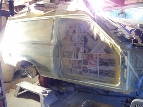
Got busy in the engine bay on Sunday and primed it this evening. First time doing an engine bay, couple of runs, not really bothered at this stage. Was tighter then your mum in there. Picture before i pulled it apart for engine spray. Most complete its looked for a long time.
1 point
-
Flashback to better times..1 point
-
come on now, we've been through this. assless chaps are chaps assless pants are chaps assful chaps are pants pants are pants an assless can am is a segway1 point
-
More on "rusting my wall" later. For now ill just show one of two side tables i made while money was short and used up the rest of the material from the hallway cupboard. They weigh a ton and have Strayan red wood (i think) tops. Ive oiled them since the pics so are much darker nowadays. Used for seats when people hit the piss at mine too.1 point
-
So close! I started on the nose today, the plan is to make it like the inspiration car... Ill start shaping it soon. He's a wee champion, not even 3 yet and he's a pro on the tools. He wont let me out in the garage with out him.1 point
-
took this 5 mins ago1 point
-
1 point
-
1 point
-
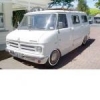
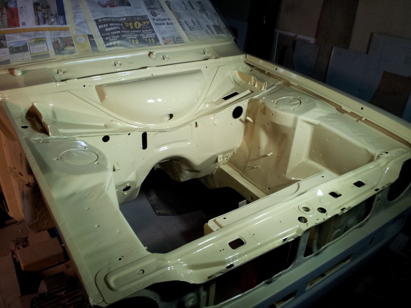
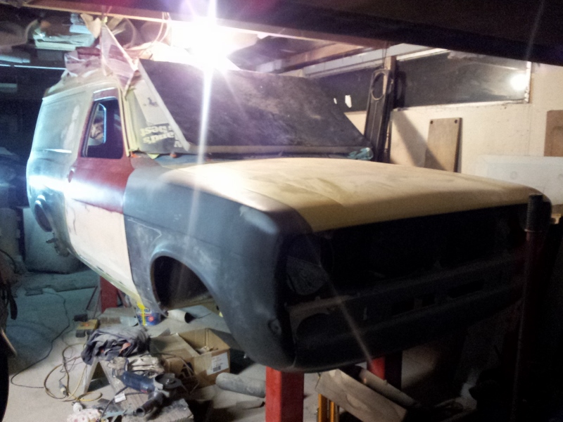
Thought it was about time to start a project thread. Picked her up from the mighty tardme in chch. Drove her home and on the way up the gearbox started doing funny things. Fun. After some research and a mate coming over turns out they run the same gear box as a MGA and he happened to know where one was. Got the box at a steal. $350 balloons then over a month started fettling. Got her up in the air and the first thing i noticed was this. god knows what they were thinking. ha. Then under all the mud along the rear was a bit of cancer. I'm going to jet wash the rest of the underside this weekend and scope out how bad the rest it. While pulling out the old gear box checked over the hoses. Have replaced the hose and slave cylinder at the same time, (no pics yet) The thing was dropping oil like nothing else i've owed the whole way back so again while it was up in the air had a look see and found this. Some on in their great wisdom had tried to repair an oil line with solder. Pissing out so pulled that out and braised it up. leak fixed. After that fitted the good gear box. Turned it over and the fork was hitting the fly wheel so off it came again and fitted the one off the old box. Drive shaft was about 200mm too long so got a spare and took it to Drive Inn (at xsspeed recomendation) great guys. The one i sent them was dented so they couldn't use it. He then quoted for him to use the bits he could and build a new one 3oo + gst. Very reasonable. After a week it was back and back on the van. Few earthing issues sorted and fresh oil all round and shes alive. (will update with pics in the next few day of gearbox etc.1 point
-
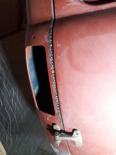
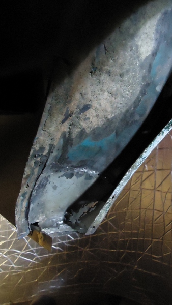
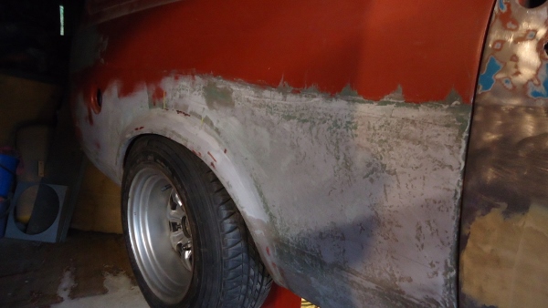
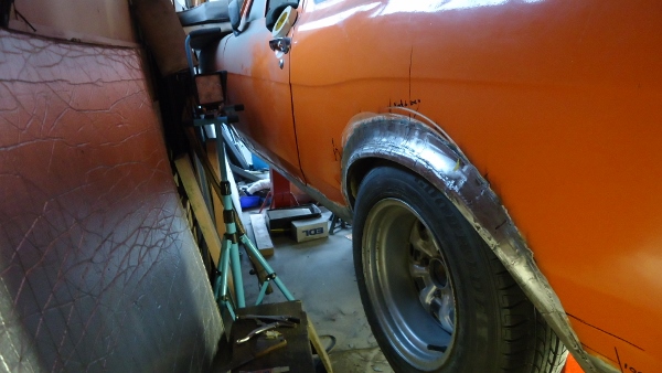
It just didnt look correct so after alot of measuring i decided the passenger flare didnt match the drivers side and stuck out 5mm too much in the centre. Decision was made to cut the edge off and move it back. Wasnt too much hassle, just disheartening. Finished the rust work in the corners under the flare while i was there Took away the supports and sat it down on the reset leafs to see how low it sits. Bonners all round. 99% happy with it now, need to cut another small section of the flare out and move it back in. 2 steps forward, one step back it seems
1 point
-
1 point


This leaderboard is set to Auckland/GMT+12:00