
Leaderboard


Popular Content
Showing content with the highest reputation on 02/05/23 in all areas
-
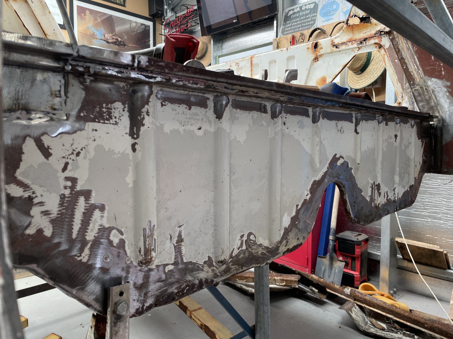
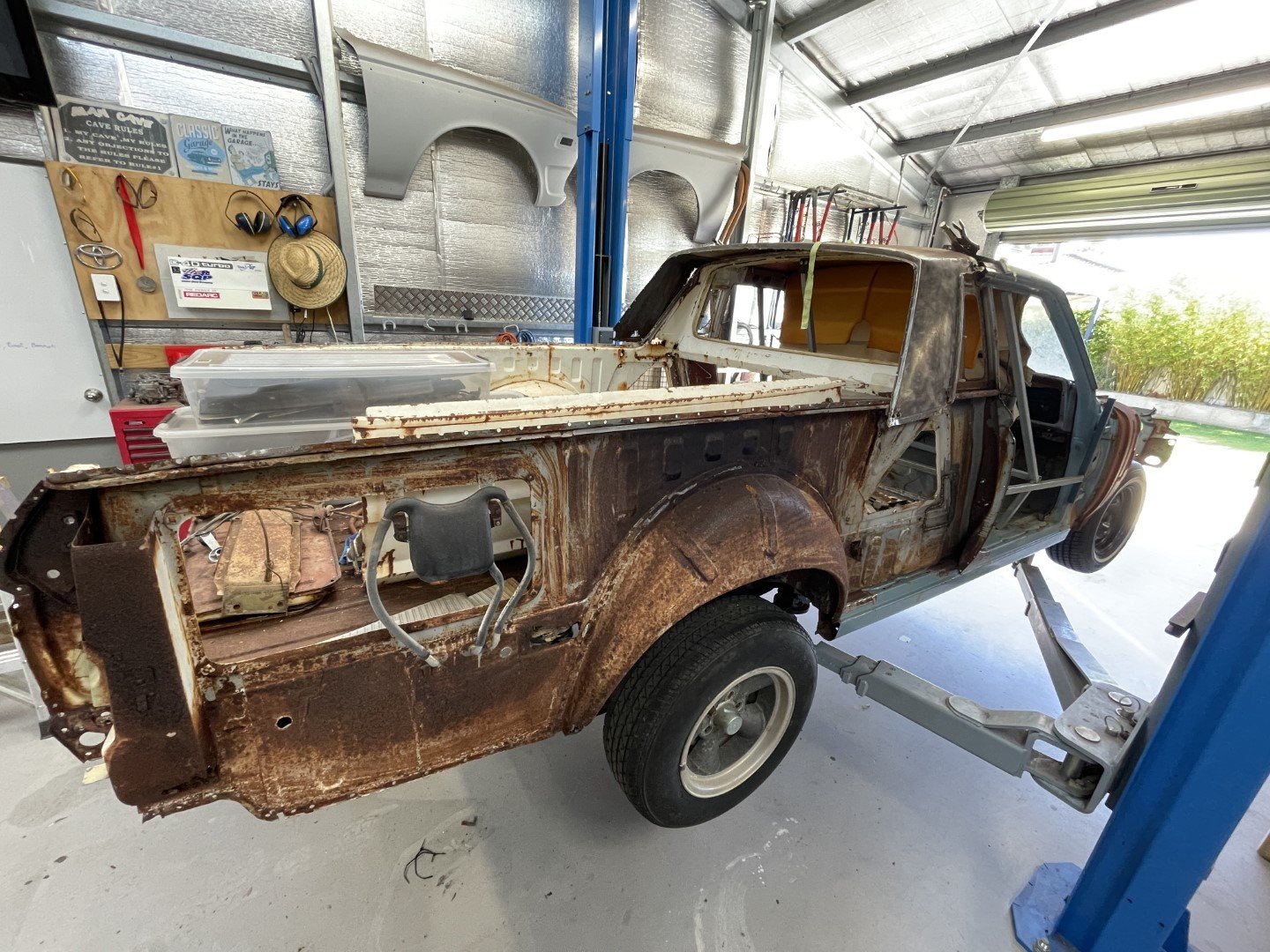
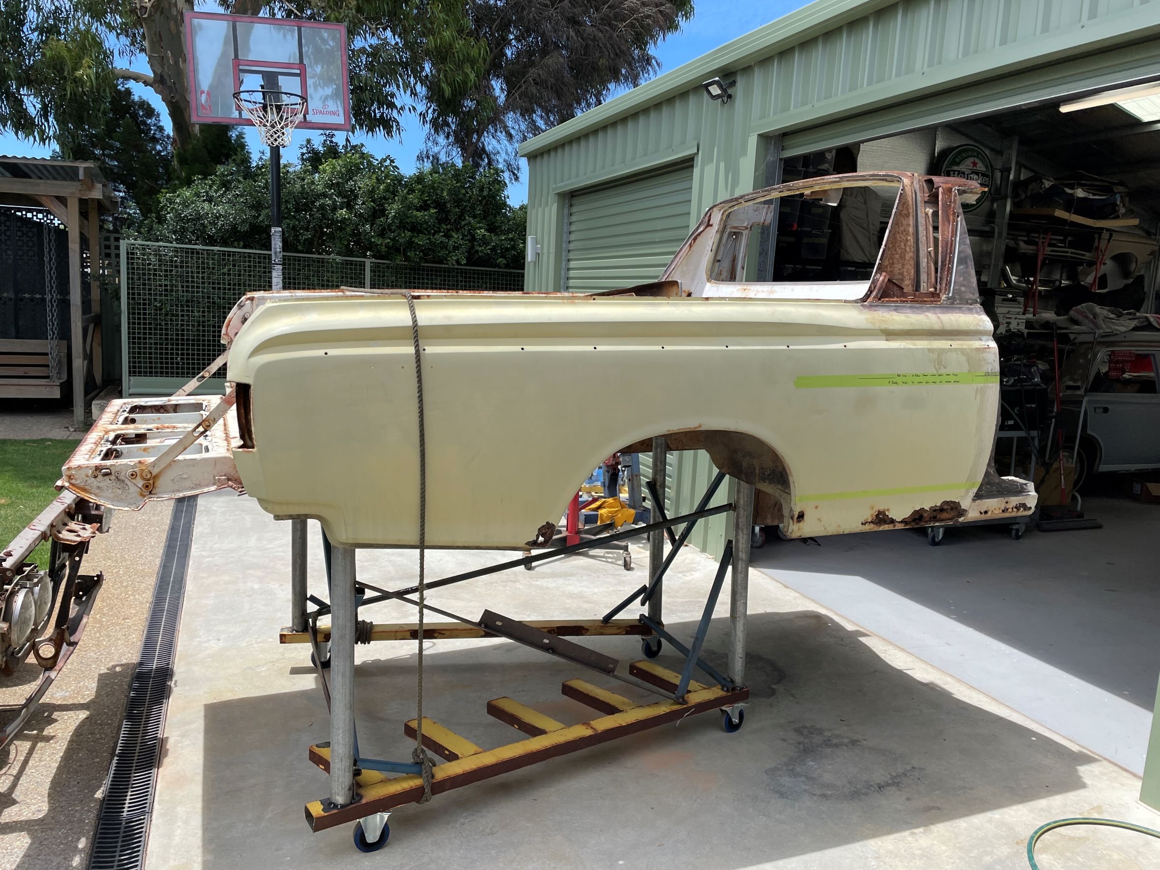
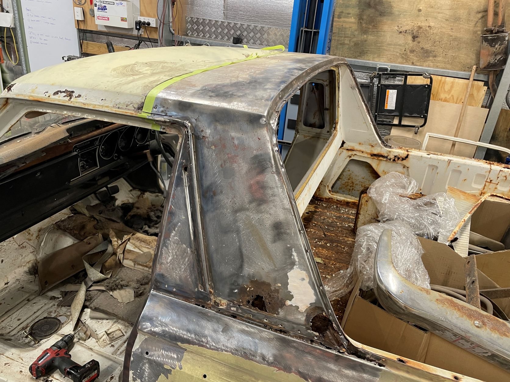
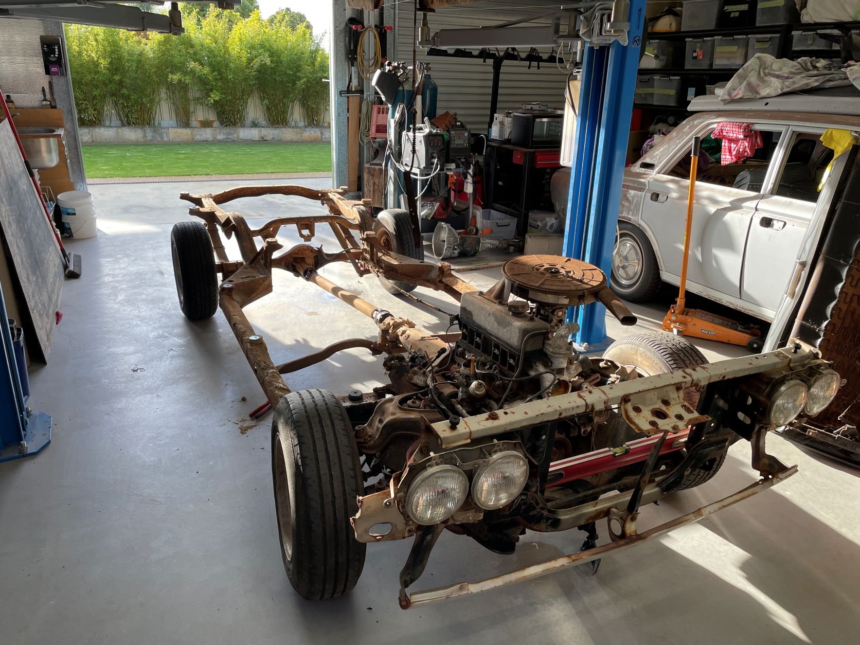
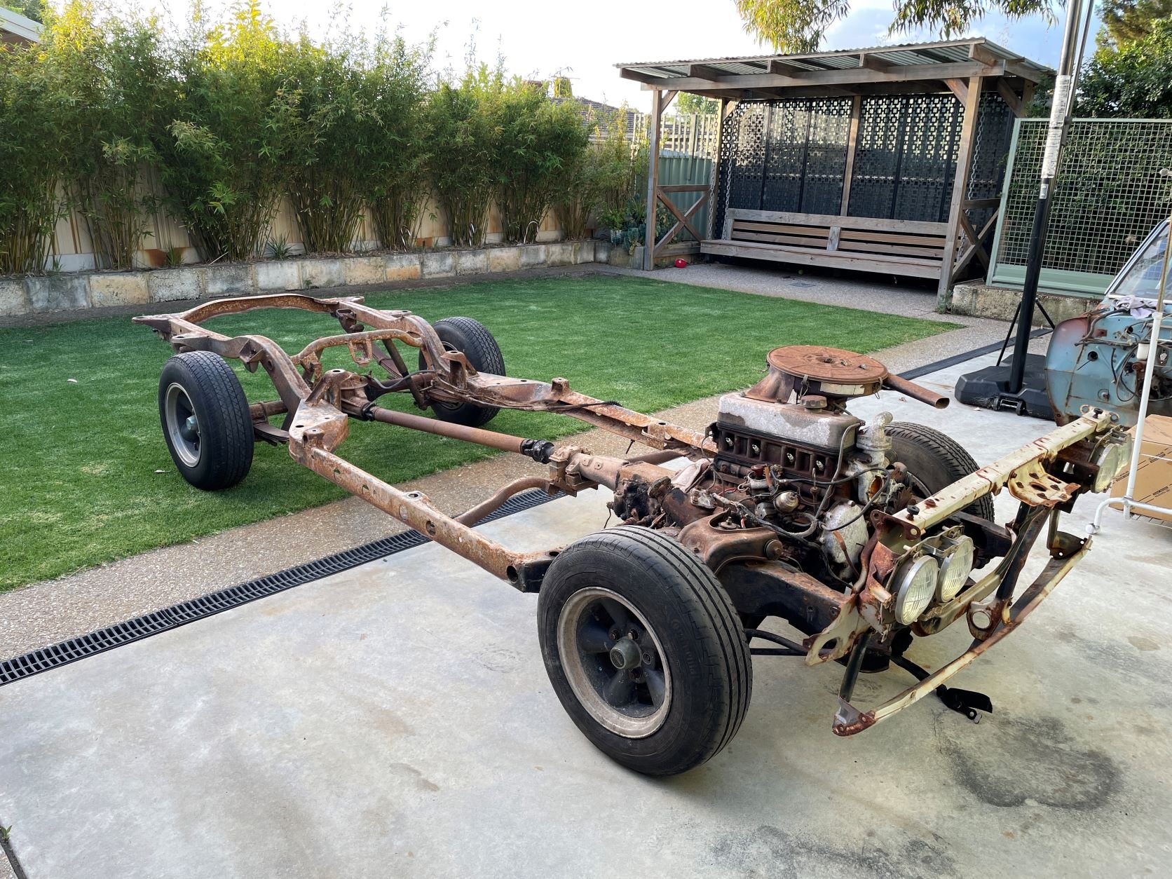
Hectic days since last update - but still alive to tell the tale, so that's good. Got stuck in and welded out the replacement steel - then spent a FUCKING ETERNITY grinding back the excess. Yet another spot that no one will see (but I will know about) so whatever. Inserted replacement steel into the lower sections that were rotted out too. Decided to drag the TIG out and have a crack - the idea of ending up with a flat weld that would require minimal grinding made me all tingly downstairs. The welder I have is an Everlast 256 something something - TIG + STICK + PLASMA. It came shipped with a 15A plug - which promptly melted once I tried dialing the plasma cutter up to 11 (60A) to cut some 16mm plate - which resulted in an upgrade to a 32A socket and dedicated circuit. The issue with that is there is only one 32A socket in the shed - and it's never where I need it to be. Found some heavy 3phase cable that I was saving for a rainy day (hoarding) and used it to extend the lead on the welder. After putting my electrical ticket away, I got my welding ticket back out and jumped straight in. No warm up. No test piece. Can you tell? In all fairness - the small torch I used at the start had an issue (seems like it's drawing air in somewhere causing a shitty arc / oxidized the tungsten) so after changing out to the ultra large hand piece that came with the welder I got stuck in. Turns out the only thing rustier than this ute is my TIG welding skills. Anywhoo - one massively distorted (but flat-ish) weld later; Planished the weld and gained some flatness back. Called it good enough and moved on with my life (which meant packing everything away until the next available time slot) 5 days later - operation 'clean up the backyard which looks like a fuckin junkyard' was put into play. With the tray section on the trolley, the cab section on the hoist and the chassis sitting outside ruining the aesthetics of the backyard - there was a whole heap of car spread out everywhere. So I slipped it all back together. It's amazing how much room you get back when you put a car back together. Added hanging panels for maximum AWW FUCK YEAHS. The wife has scheduled me some shed time on the weekend - that will hopefully give me the opportunity to do the final line up before welding the two pieces together.
 14 points
 -
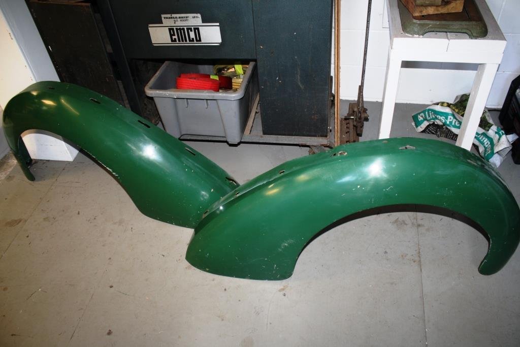
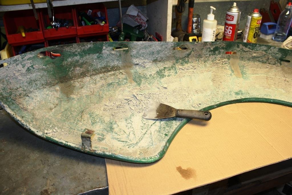
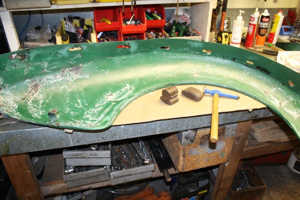
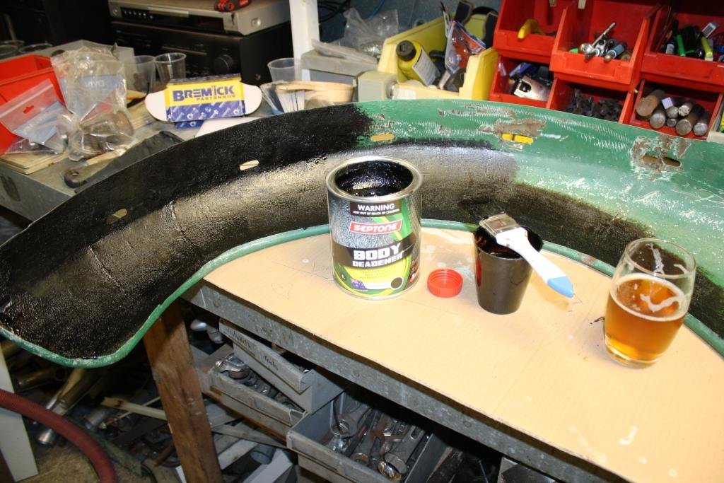
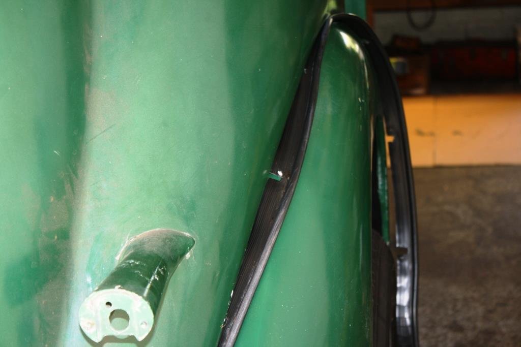
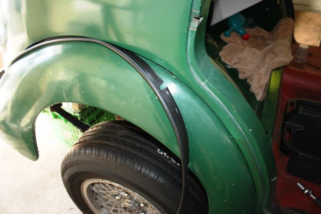
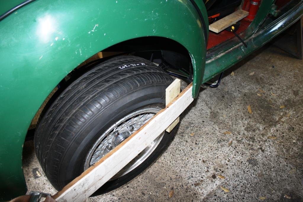
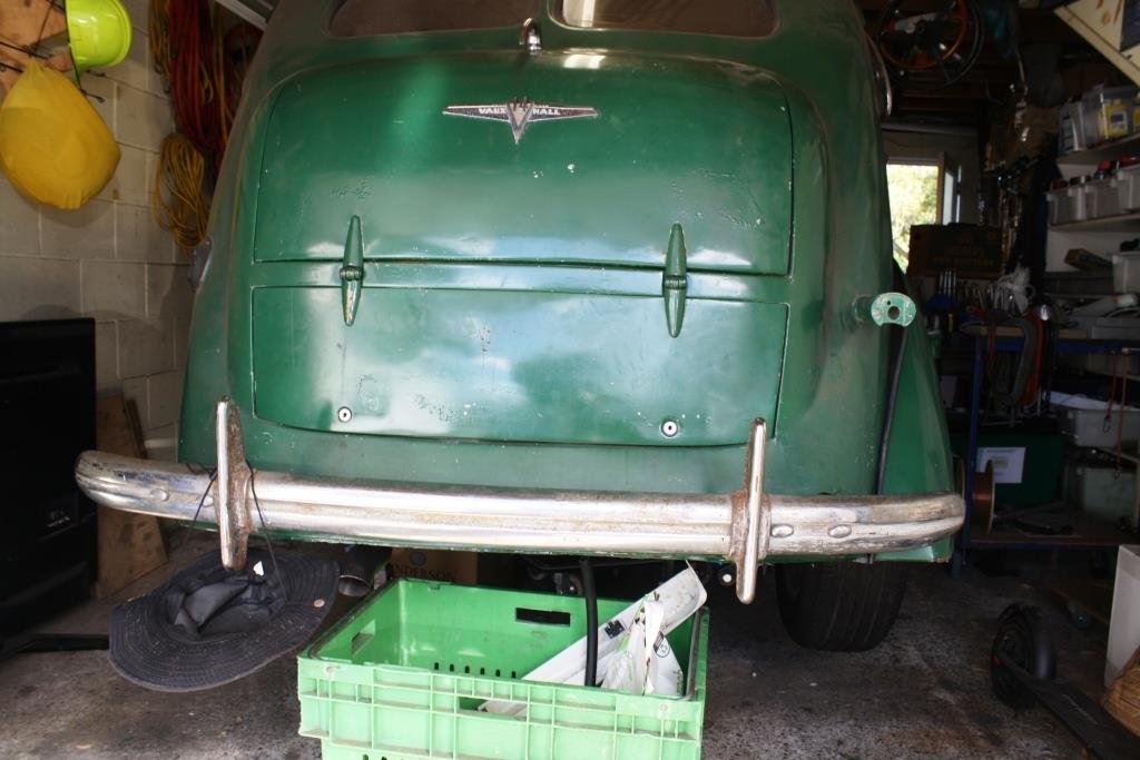
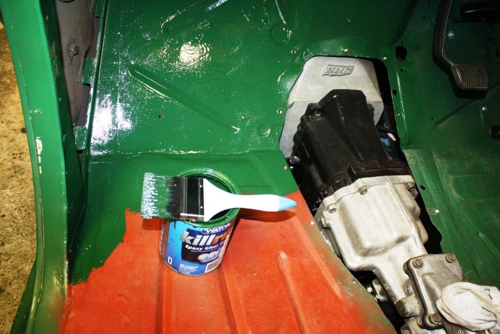
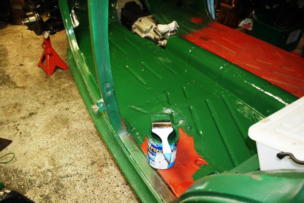
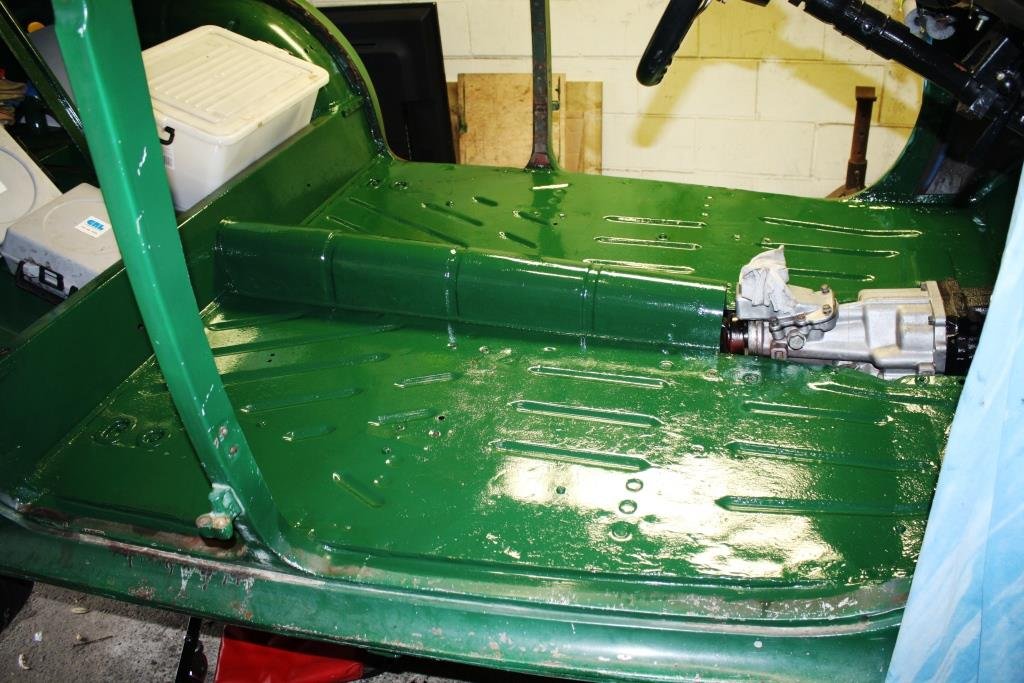
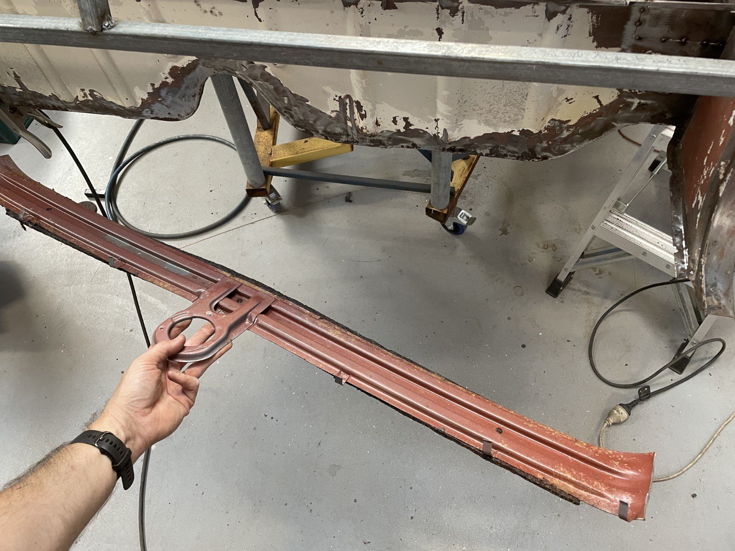
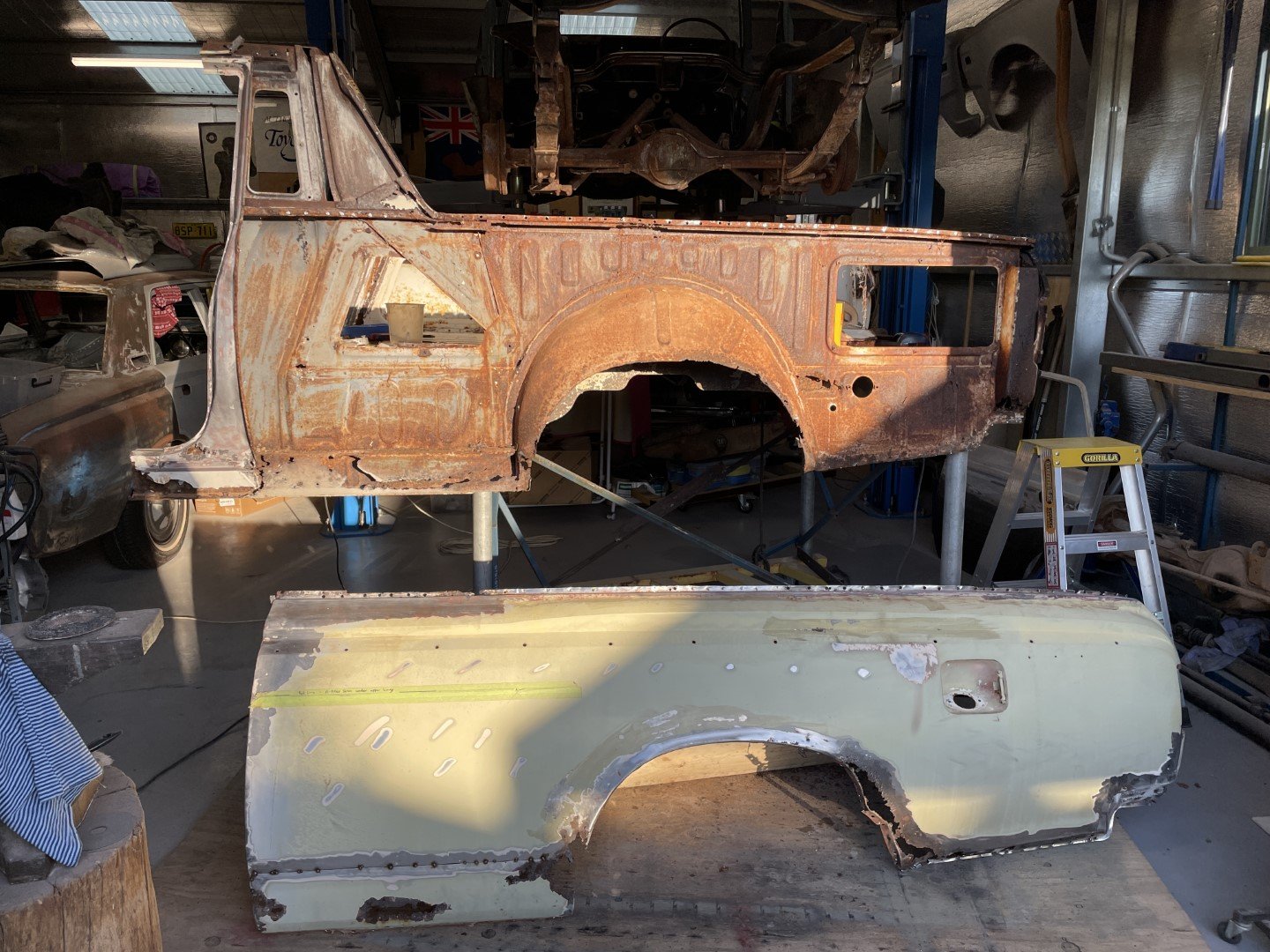
Thought I’d have a play with some body work for a change. Dug these two out of the parts shed… Started scraping…. Did a little hammer and dolly stuff… Then some underseal… Bit of a mission getting things to fit…. Had to massage the front of the guard for clearance… Happy with the result. Time to finish painting the floor with the famous “insipid green”… 2 coats and I’m over painting.
12 points
-
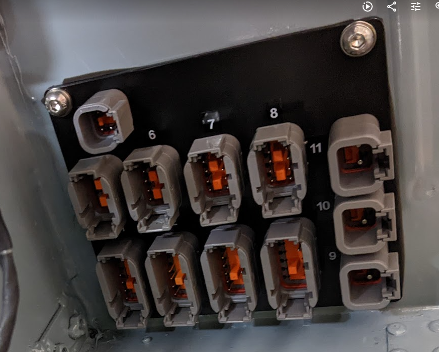
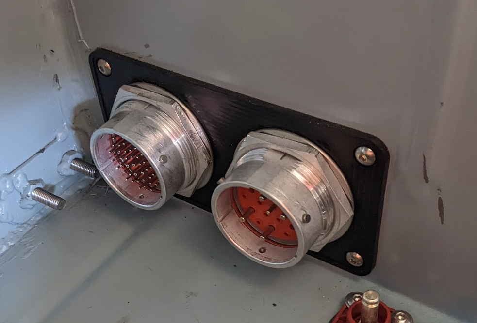
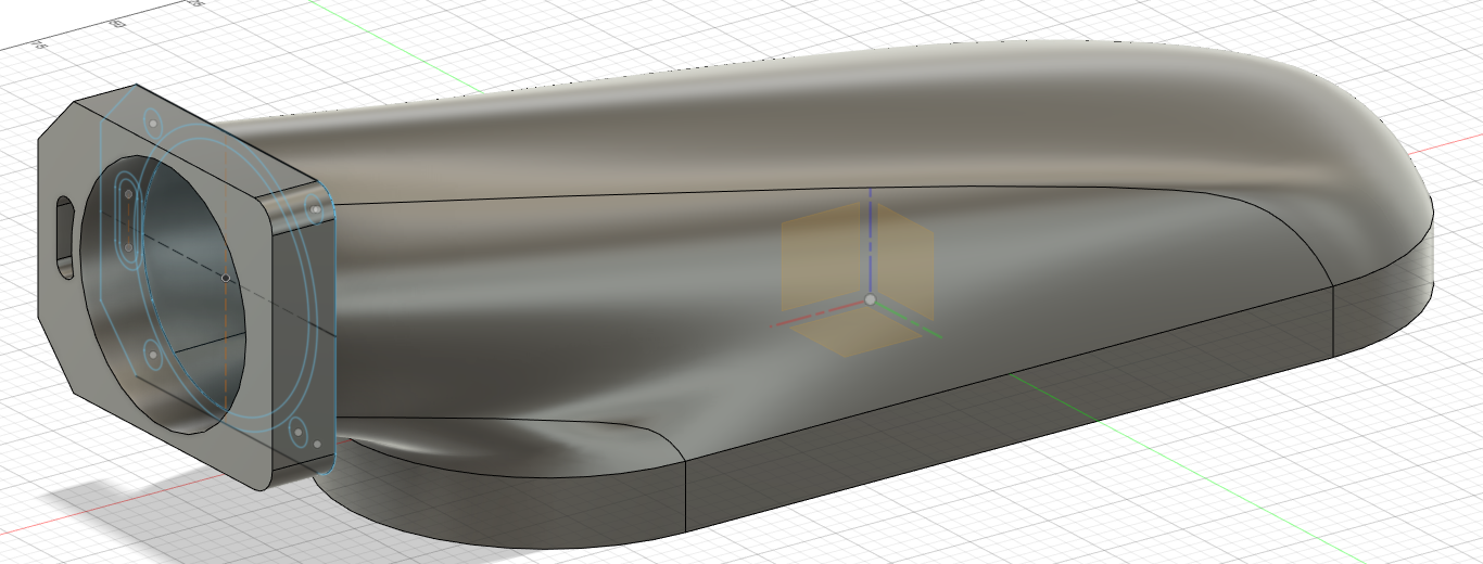
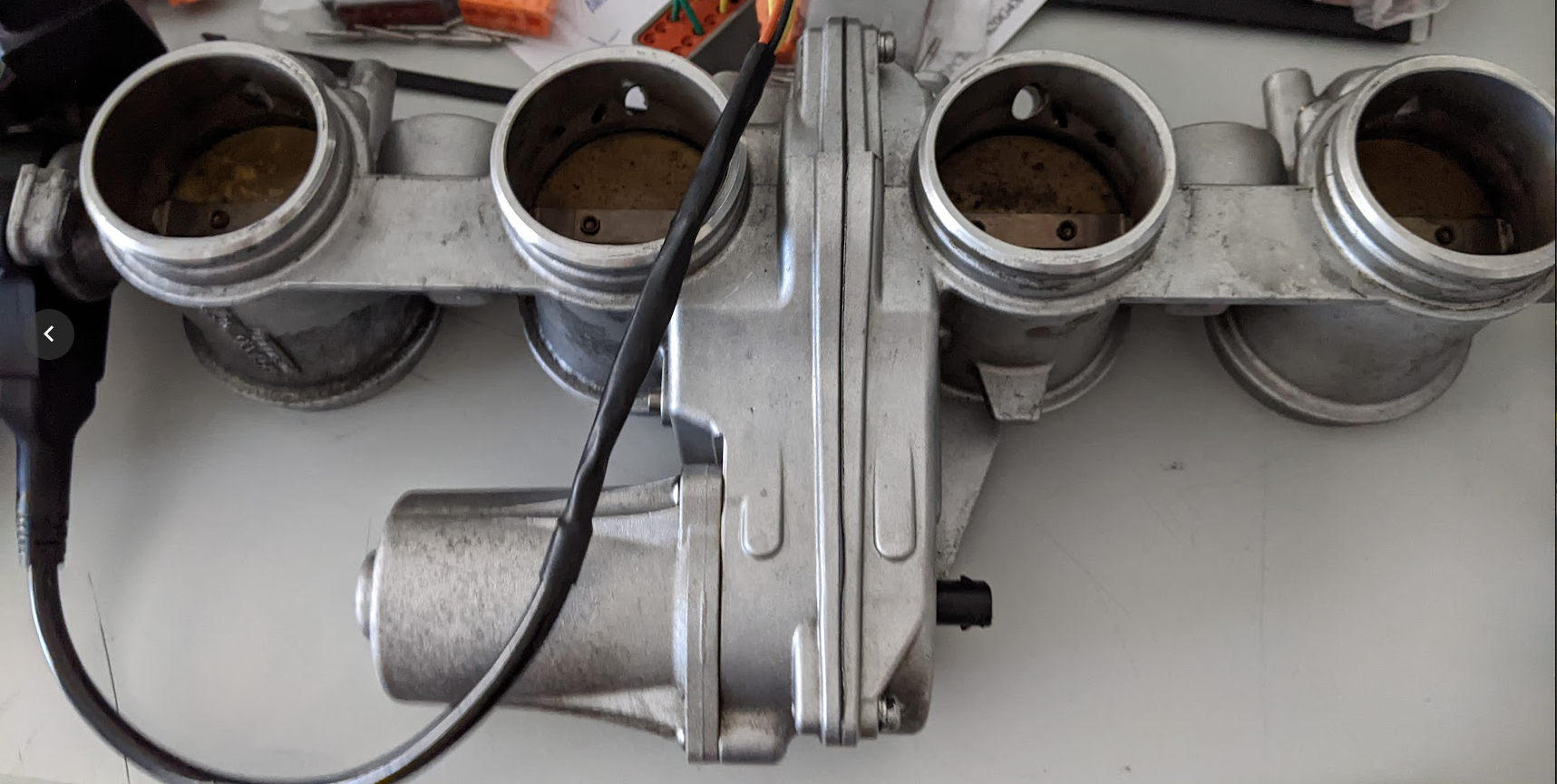
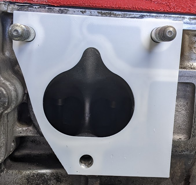
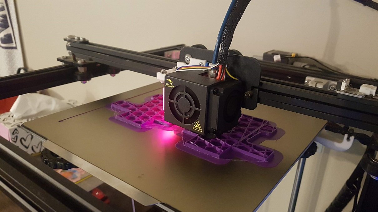
So I acquired a 3d Printer a wee while back and I've been learning how to design and create prints, and I finally had a cool job race car job for it. I needed to lengthen the Watt's linkage slots so I can lower the linkage to get more grip out of the corners, and it's really important they are straight to keep the axle alignment. So I 3d printed an insert that I could then outline the slot and center point for drilling the end of it out. Worked a real treat and allowed me to do a much nicer job. So the big downside of using @Roman ITB's are they are electronic, this means 2 TPS sensors, 2 pedal sensors new relay to supply power to the B plug of the ECU controlled by the ECU, and repinning and moving connections around. I had thought at the time when wiring the car about DBW and thought "na I'll never go DBW" Sigh. So knowing it was a pretty big job I thought it might be worth remarking the top of my current manifold as an interim measure, so with Daves help I designed up a new top cover. But once I got to that point I could estimate the amount of material need to print it and I was also very concerned with the strength of it hanging off the side of the engine with throttle body with the only attachment being bolts threaded into it, I'm sure it's all solvable with time and effort, but I knew I wanted to do ITB's so scrapped that plan. It did give me lots of experience designing a complex shape which was good. So onto the wiring job. My goal was to rewire ready for the ITB's but still run the Intake manifold for now. So I previously had these bulkhead connectors to the engine. And they are nice, however having had them on the car for a while I wasn't happy with them. They are big, but more importantly they are impossible to work on e.g. good luck getting the very center wire out. They do make it much easier for when testing the wiring as they provide a nice test point for connections, but otherwise they are really ideal for if you had another engine with the loom ready to go and drop in, but in reality I'm not a big race team doing that I'm just a club racer. So my goal was to create something that was more modular that I could upgrade/add bits over time easily. So I designed this in Fusion 360, printed mockups got it to how i wanted it, then had it laser cut and then @ajg193 machine the slots for the clips on the back side. It has standard Deutsch DTM/DTP connectors which were a bitch to work out how to retain, and they still aren't quite right (but that's to do with the clips on the back and I think I can do something better). But it will work for now. Really happy with how it turned out. It runs the following. 1: DTM12 (Front of engine) - Crank, Vtec, VTC, Oil Pressure, Oil Temp 2: DTM12 (Back of engine) - Exhaust Cam, Intake Cam, ECT, Starter, Alternator feed 3: DTM12 (Intake) - IAT, MAP, TPS Main, Fuel Pressure, ISCV. 4: DTM12 (Front of car) Transponder (can deal with lights etc in the future if required) 5 DTM8 (Gearbox) Speed sensor 6: DTM8 - Ignition Coils 7: DTM8 - Inboard Injectors 8: DTM8 - Outboard Injectors (not used at present) 9: DTP2 - ECU Ground to engine head 10: DTP2 - EWP 11: DTP2 - Fan 12: DTM4 - Can Lambda Connector 3 has everything wired up for the ITB's as well so just need to change engine side to suit, also potentially supports variable velocity stacks (BMW S1000R comes with them as standard). The idea is If I suddenly need a new sensor, I can easily splice it in to the engine side, and just run a single wire back to ECU. I've also wired extra sensors into the steering columns for the pedal sensors and clutch in the future so they will be straight forward to add later. Car is finally back together, It's running but I need to get it out on track again just to make sure everything is still good.
9 points
-
Gooder
9 points
-
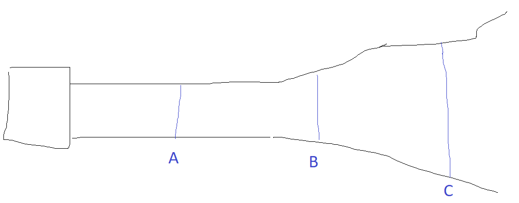
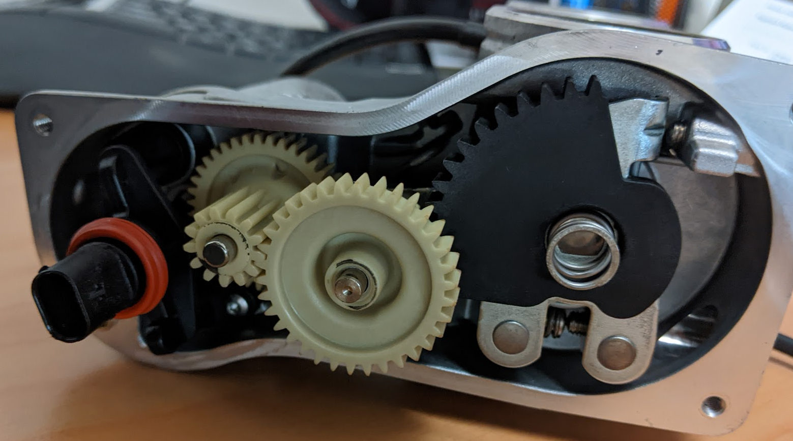
ITB's Next Step So the wiring is now done just needing testing. The ITB's are a long term thing I need to slowly work through. So while rewiring I pulled the manifold off so I could measure the ports and create a flange in CAD so I could slowly work on the manifold adapter. So much crap on the internet I did a lot of research on the internet around K20 ITB's and the port sizing, and can confidently say some manufacturers have both the port angle and port size wrong in their drawings (and that's their job to get right) Jenvey are definitely the ones who have it the dimensions right and that's backed up by feedback from someone who has tested a few and found them the best. The jenvey ones are 48mm and everyone says that bigger then that is better (e.g. 52-54mm), but that ultimately depends entirely on where the throttle blade is positioned with the system. e.g on the following diagram, A, B and C are all different plate sizes but really have no impact on the amount of air being ingested, however position does have an impact on response and driveability (closer to head being better). So the Honda K20a CL7 port size is equivalent to 46mm throttle plate, which means if you put the throttle plate at B (48mm) you have accounted for the restriction it causes. Jenvey looks to keep a straight section (no increase/decrease in size) of 46mm diameter for a length of 85mm from port to throttle body flange. I suspect that is because you don't want to take energy away from the air by trying to increase it's velocity just before it goes into the head, but could also be packaging etc. I'm just speculating here. Additionally Jenvey have the port angle at 17.5 degrees, which when I measure is perfect for dead center (vertically) of the port as it narrows. Where as they others have 14/15 degrees which means the top side has a sharper angle then the bottom (which is flat). So I can see why Jenvey perform, their experience shows in actually getting the basics right. So they are the ones to copy as I can't afford their full kit BMW S1000RR ITB's Now the S1000RR ITB's are 53mm entry, 48mm plate and 42.84mm exit with a 3.5 degree taper on walls. The exit is not good if port size is 46mm., however I'm confident I can bore them out with a little effort on the lathe to 46mm which would be perfect, I only need to bore 10mm into them, so don't have to worry about the throttle plate. So I pulled them apart to see how hard it was and if it was possible to put each half on the lathe as is without having to completely dismantle the plates Then they wouldn't go back together, a small bit of panicking later I was thinking I would have to dismantle them which would then mean they needed to be resynced. But in the end I 3d printed a tool that now allows me to put them back together as they were from factory, so that's a massive win. Bore spacing was the other worry the ITB's are roughly 83-82-83mm and the CL7 is 94mm, but it turns out that it's close enough that it will be fine. So I can proceed with the ITB's and the design of the manifold to suit them. My intention is to mount the standard Honda injectors into the manifold in the same place as the Skunk2 manifold (close to head) so that the transition of the tune to the ITB's is easier, then setup outboard injectors at a later stage (and just block up the BMW ports). I'm not rushing this so it will be done when it's done. Just in comparison here is what others have done to fit bike ITB's to a Honda K series. https://www.jimbositb.com/product-page/throttle-body-adapter-plate-k24 https://danstengineering.co.uk/Honda-Civic-Type-R-K20A-Bike-Throttle-Bodies-Kit-GSXR1300-46mm-STARTER-PACK Feel free to tell me I'm an idiot here;
8 points
-
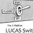
A water pump pulley turned up. It is the wrong one, made for an 1800. It fits well enough to run the engine, it just pushes the belt alignment out by about a belt width. Good enough for tutuing about with. The correct one is apparently on the way with a return courier bag for the wrong one, so can’t complain too hard. Anyway, noisy tappet was very apparent so while I still had the shim kit I went over them all again. Success! Quiet tappets, good oil flow etc. I got the boss to help me bleed the brakes which took ages. No end of air bubbles but we got there in the end using nearly a litre of fluid! One thing confused me though, it has a dual remote reservoir as it’s a dual circuit master. The fluid only went down in the rear reservoir for all 4 brakes?….They seem to be working well though. There was a horror moment when I walked into the shed this morning and found a large puddle of water under the car. It was dripping down the bell housing area so I immediately thought the worst and assumed the steel water jacket cover was leaking which is only accessible by splitting the engine and gearbox. Big whew when I saw it was the heater return line on the firewall! All fixed now. Then I took it for a hoon to get the fluids hot. Goes well, clutch is all good (higher pedal effort than I remember but it’s a new cable so might loosen up?) Brakes as I said work nicely, but there is a horrible driveline vibration that starts up at around 70k’s. Almost certainly the driveshaft which I have maybe put back on 180 degrees out…Finished the day by putting his face back on. I have no high beams and a blinker repeater is out, so plenty to sort yet.
7 points
-
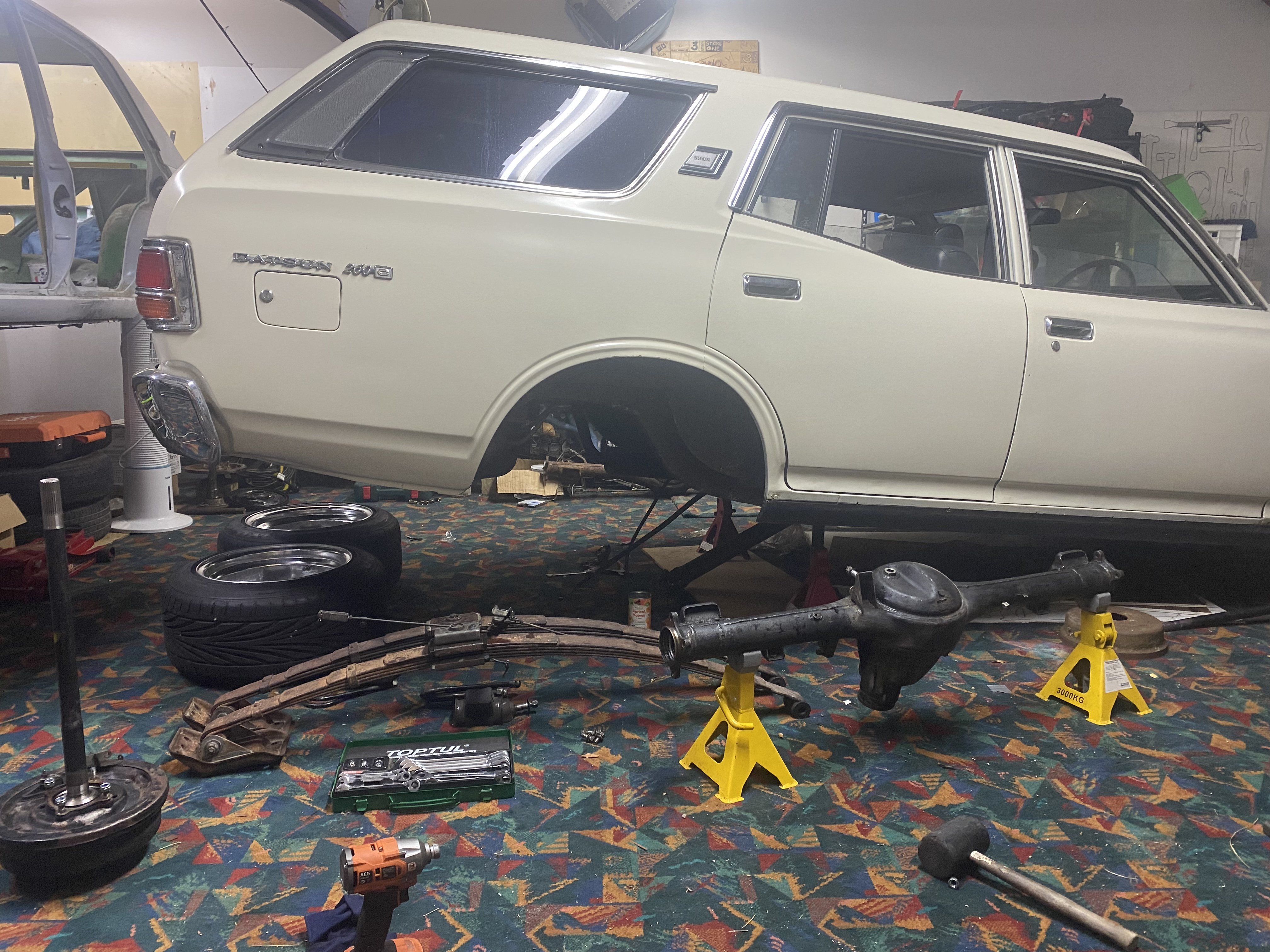
Last nights efforts, I got a little motivation to pull the rear out. Will send to chch on the next road trip. Usual expectations with the metal shavings in the diff oil. In my journey doing this, I made the mistake of stepping in the brake while the drum was off…so now I need a rear brake cylinder seal repair kit. For those curious, current diff is 100mm shorter than stock. In other news I also replaced the exhaust gasket and two into one gasket. Quiet as now.
7 points
-
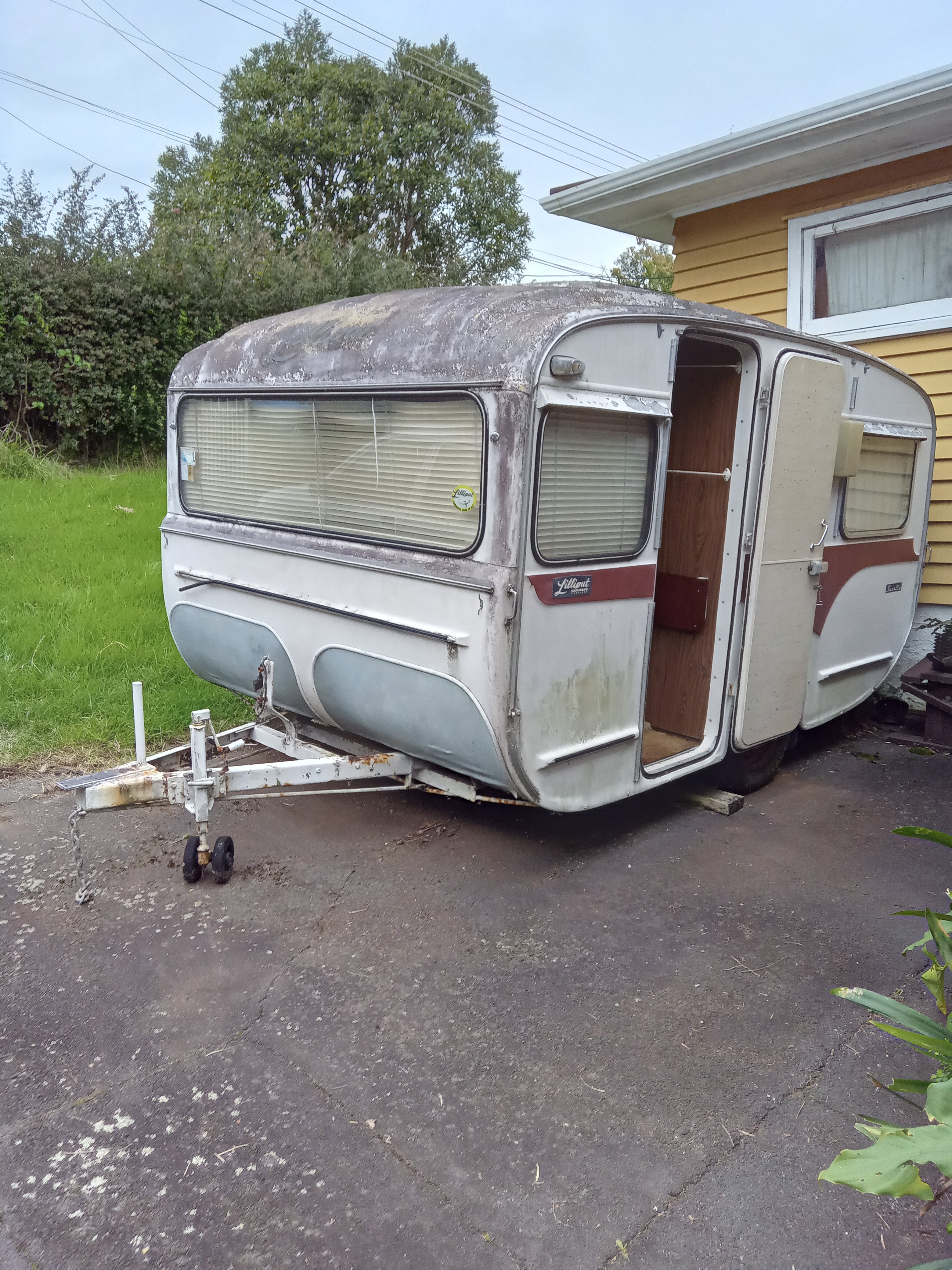
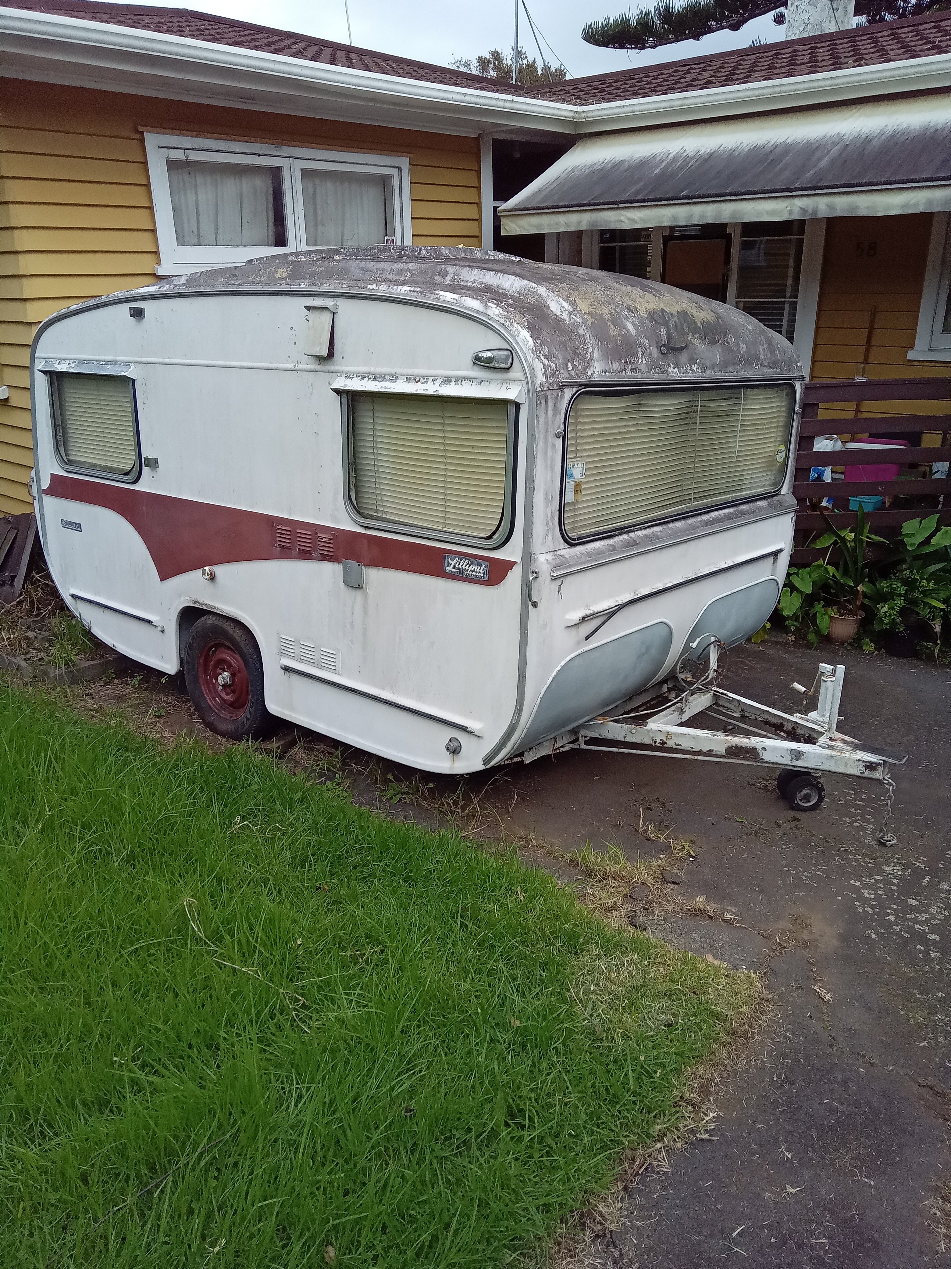
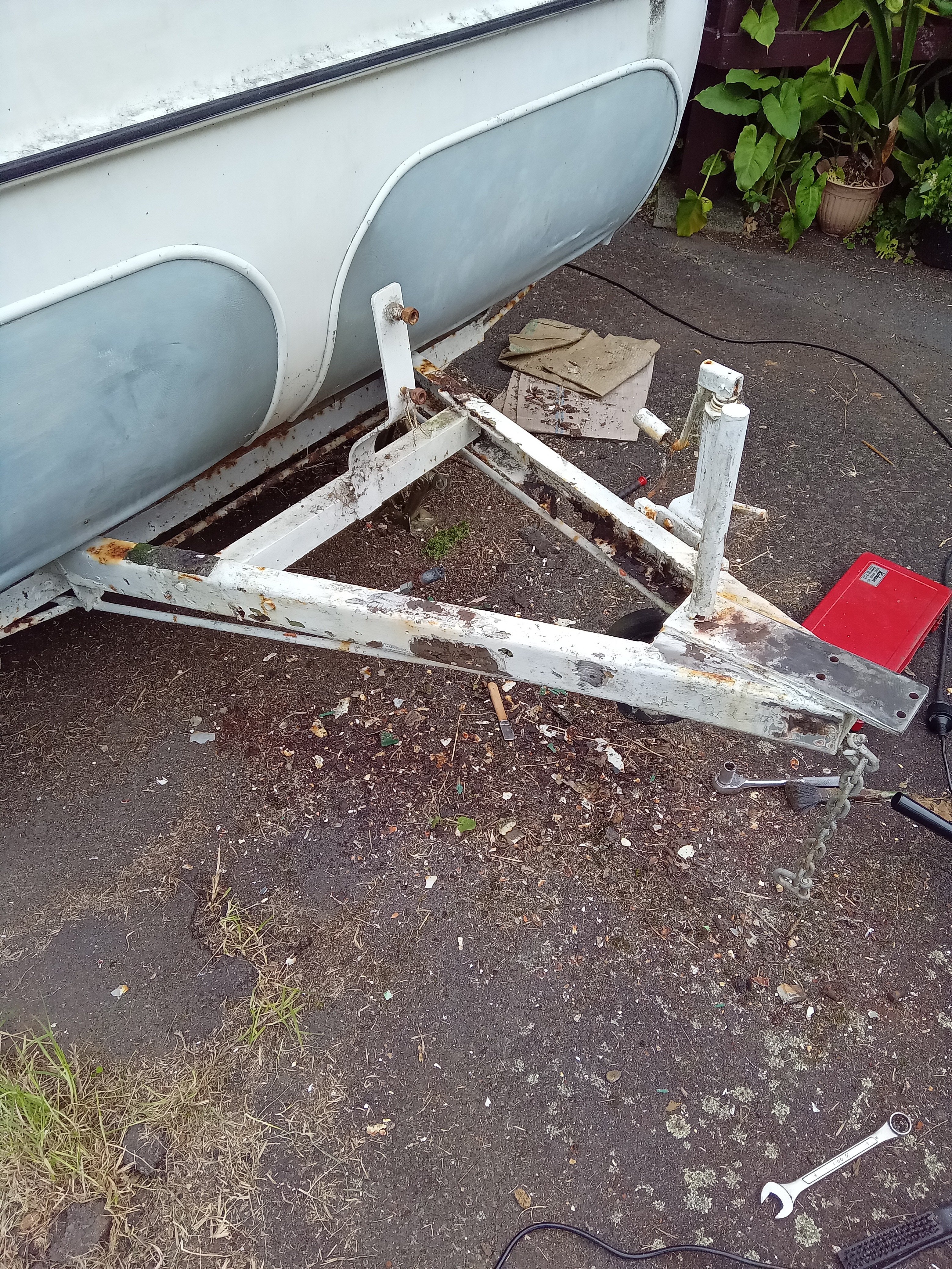
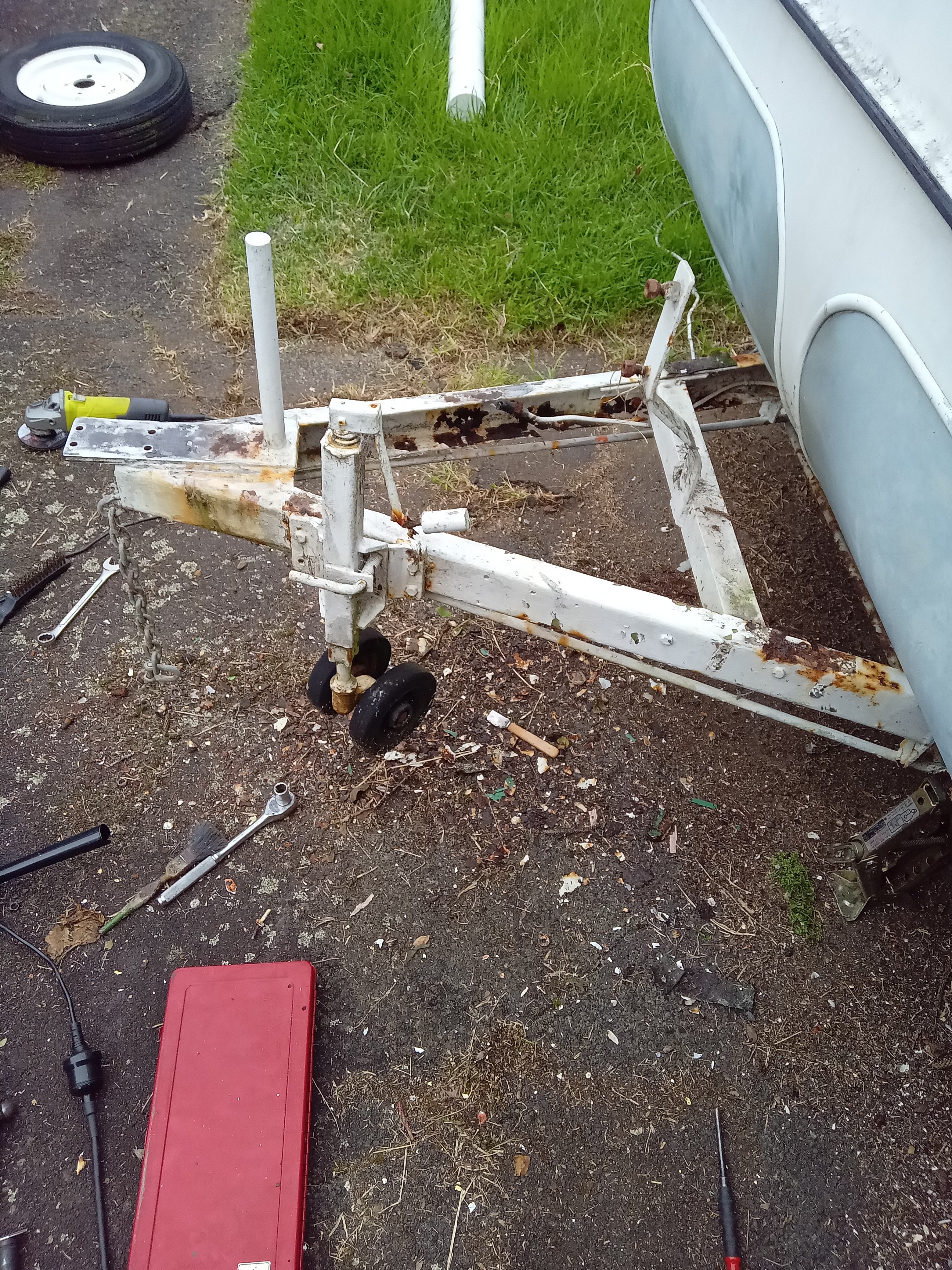
Next project 1975 lilliput caravan. Was my grandparents, they did a lot of touring around the country in it. Its been sitting for a while now. I thought it would be pretty bad but its not, it doesnt appear to have any leaks My plan was to cut off the rusty coupling and chuck a new one on, the drawbar is toast though which i was going to replace anyway Stripped a bit of stuff off so i can measure up what i need to get it mobile,then i can get it onto the hoist at work to give the undersides a bit of a tidy up I think ill just get it useable and worry about paint later
5 points
-
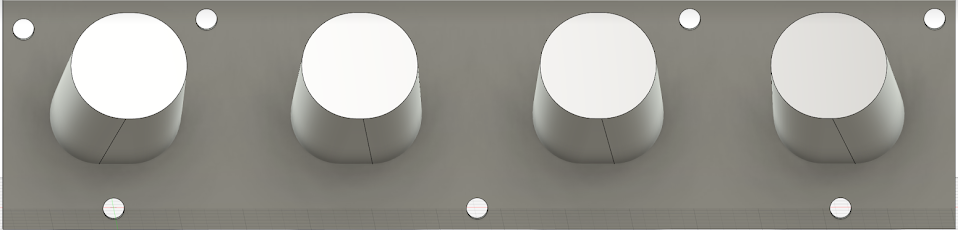
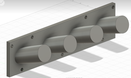
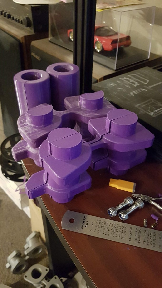
The plan is to have a crack at backyard sand casting. I don't have the tools to do any lost foam casting, which is a bummer, as this seems to make the best quality parts. Sand casting also kinda determines the shape of the manifolds too, as they need to be split-able with no overhangs or inverse surfaces so they can be withdrawn from the sand. So created some patterns, and some core molds and printed them out (at 1.2% larger as from my research, this seems to be a decent number for aluminium shrinkage). Need to give them a good sand and some thick coats of paint to get them silky smooth. But they look like they should work? I have no idea what I'm doing now. Do I get them cast at a foundry? Is this expensive? Will they laugh at me? Or do I build my own LPG furnace? Or do I buy an electric aliexpress furnace? Then I have to mill and drill the castings... I don't have a mill. So yeah, maybe I should just buy some manifolds eh? Wish I could just print them out of something and roll that. Is that at all possible?
3 points
-
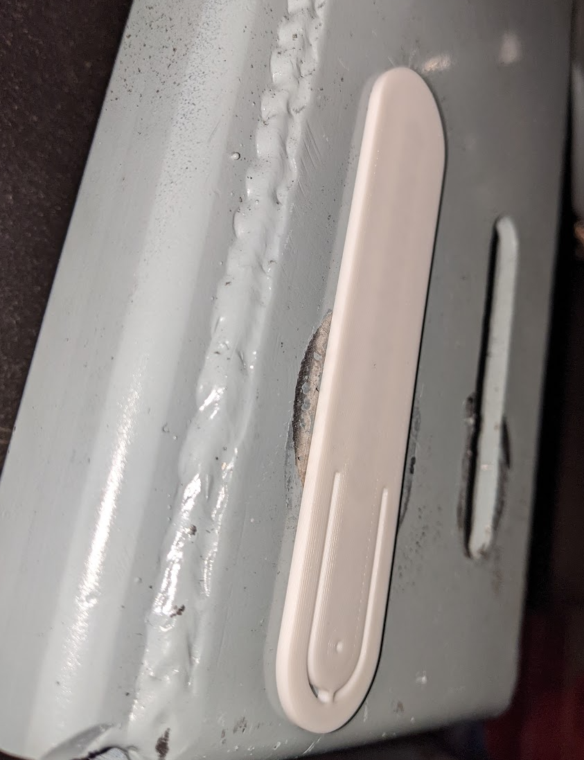
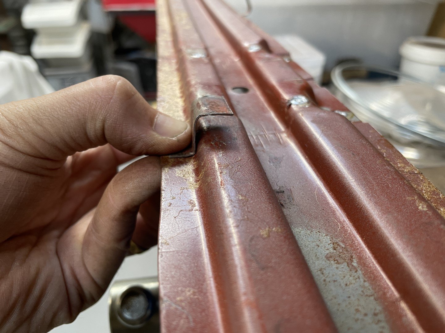
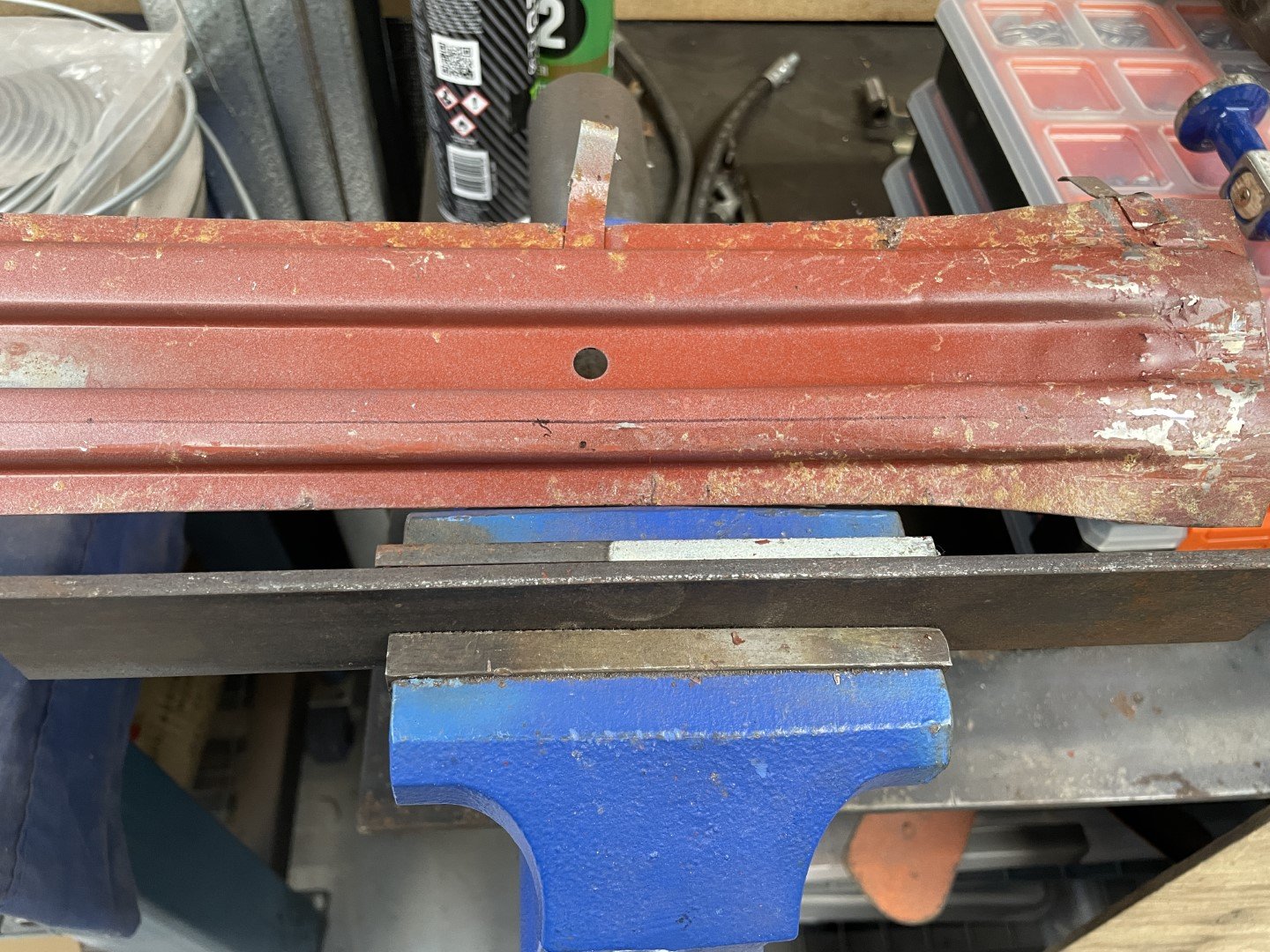
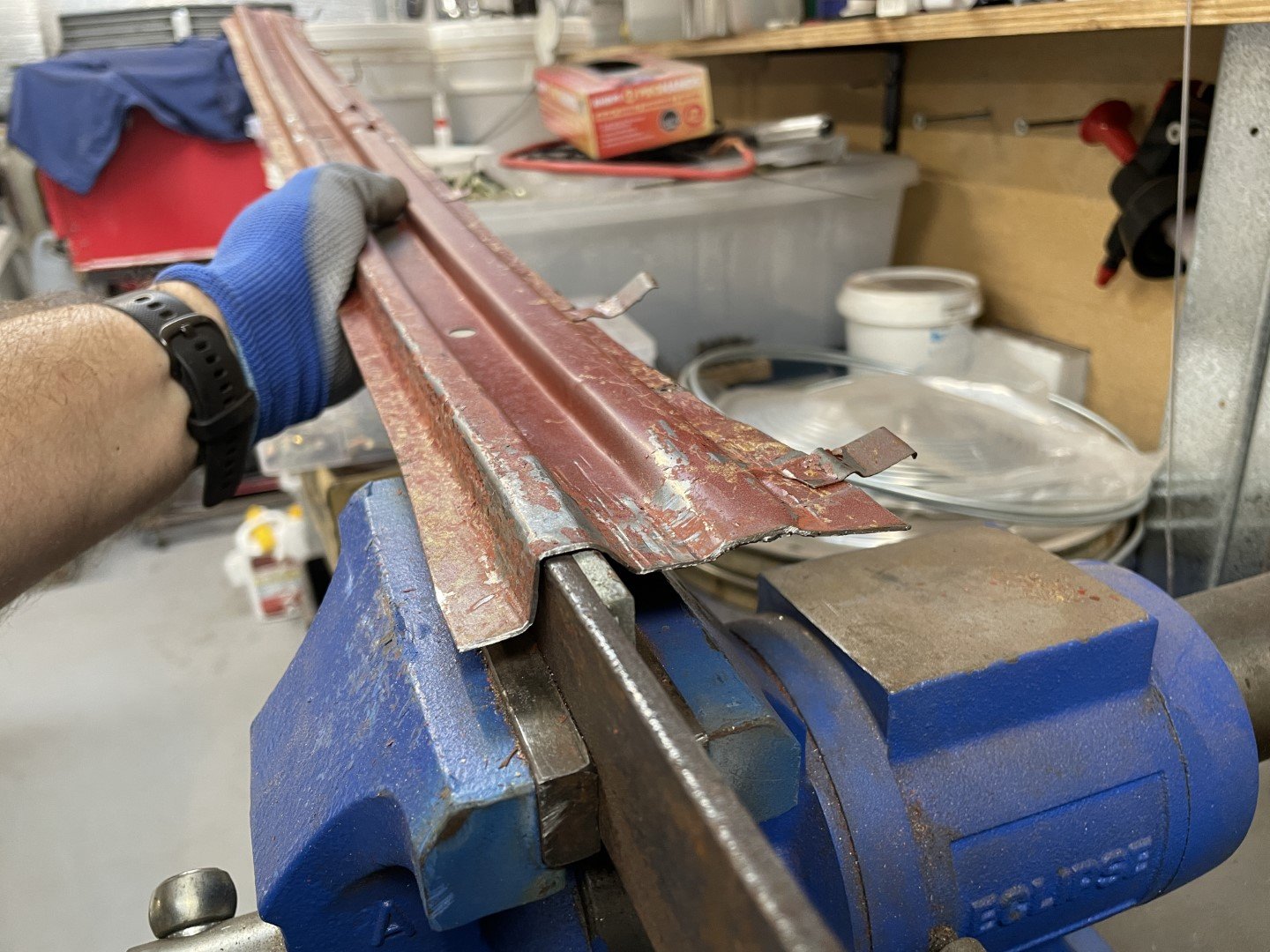
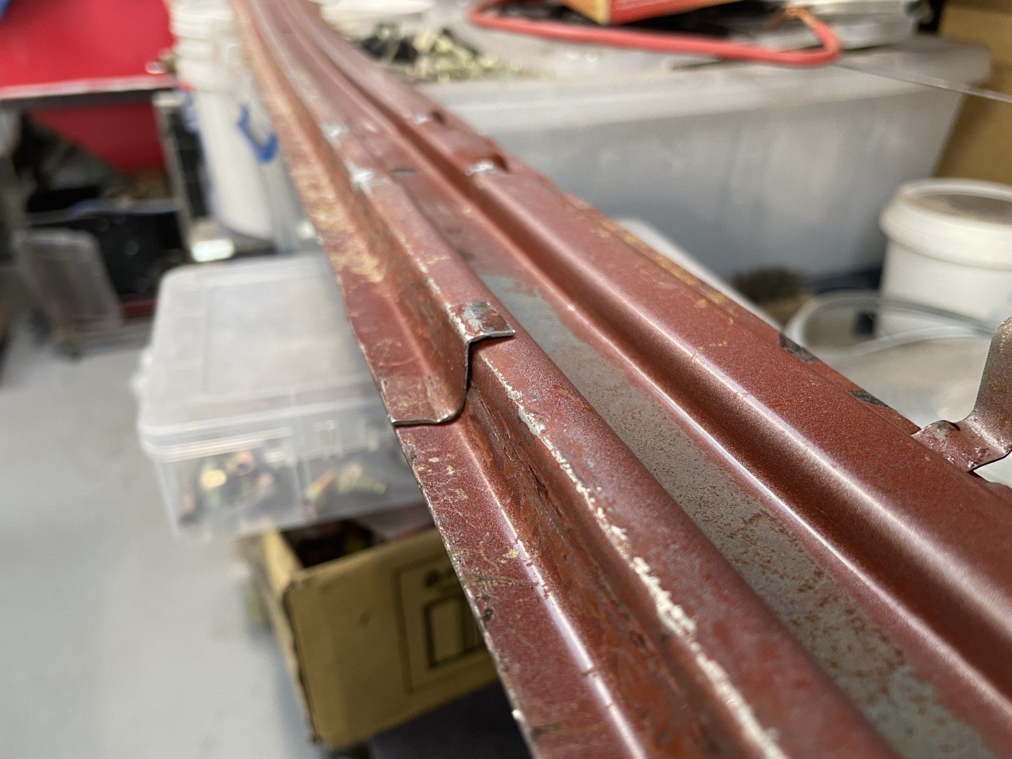
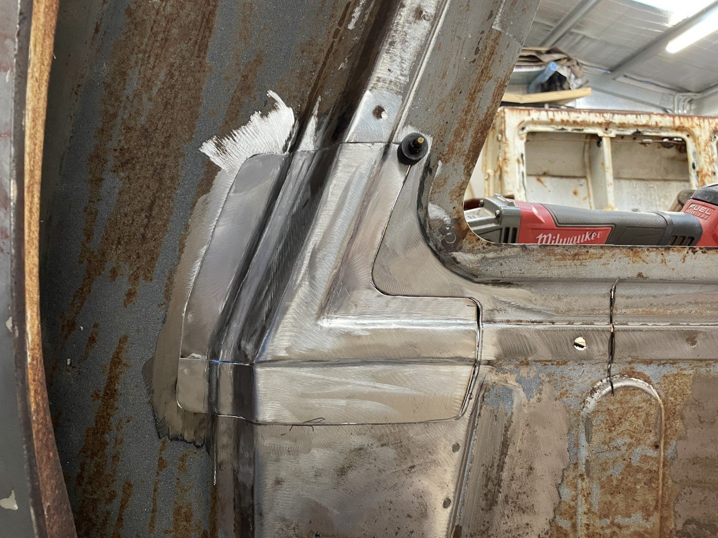
Not having a sheet metal folder (anymore.... I did have one, but sold it for lack of use / annoyance it presented by always being in the way) or any sheets of suitable steel that I could use to bend a continual replacement piece - I had to find another immediate solution. Looking at the pile of scrap metal cut from the sedan revealed the middle roof support (which had the sedan interior light bracket attached) Seemed to be close to the right length - however the step wasn't quite right. Carried on and drilled the interior light bracket off. Photo below shows the variation in step heights. Figured I could just beat the panel into submission to achieve the required profile. After marking a line for where the bend needed to be, I set a couple of pieces of flat bar in the vice and had at it. After much hammering the desired profile was achieved. After cutting the required piece away, I spent more time hammering the panel to remove the epic bow it had taken on (from having metal stretched in one area, but not the other) before moving on to matching it up with the ute body. The panel still had quite a bow to it - but knowing that welding it in was going to require follow up hammer and dolly work I wasn't too stressed. The Mrs suggested that a 5pm knock off and a walk around the block with the kids would be a good idea, so I quickly tacked the panel onto the body in a 'close enough = good enough' fashion before stumps. A few gaps were filled (including a 50mm gap at the other end as a result of the panel not being quite long enough) before I switched off the welder and headed out to get some fresh air. Also of note - I ground back the welds on the back side of the panel I welded in at the start of the day (although no one will see the welds when the rear 1/4's are back on) purely to allow me to planish the welds. Planishing the welds stretched the material that had shrunk during the welding process and flattened the panel substantially - a quick pass over with a flap wheel saw the welds almost disappear (as per above photo). Happy with that!
3 points
-
Will the Plymouth have enough torque to pull it?2 points
-
Yes, very much so. Excellent example.2 points
-
3 bond 1215 for the win, not cheap but worth it. OEM spec for Toyota/Honda etc total bastard to get apart again if you need to. https://www.repco.co.nz/car-care-panel/adhesives-sealants/gasket-cements/threebond-high-temperature-rtv-silicone-liquid-gasket-250gm-grey-1215-250/p/A1130561 I have found that hylomar required an absolutely immaculate finish to get a good seal, due to the fact it's non setting and pretty thin. The tiniest nick or gouge and you need to find something with a bit more goo to it. Disassembly a breeze generally though.2 points
-
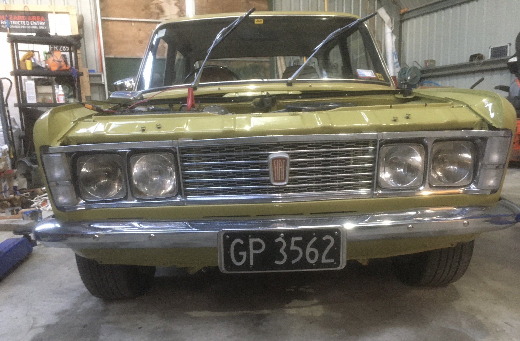
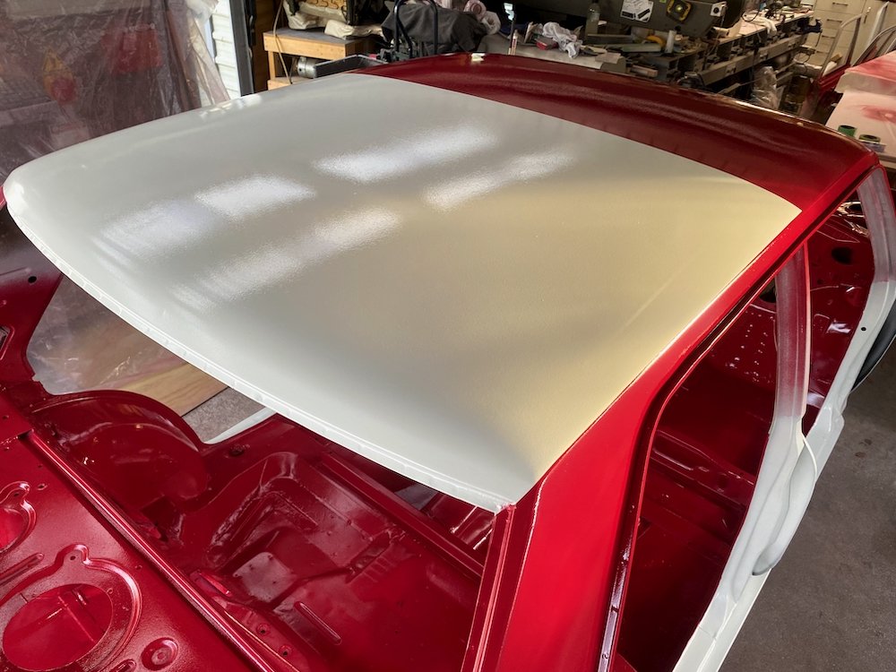
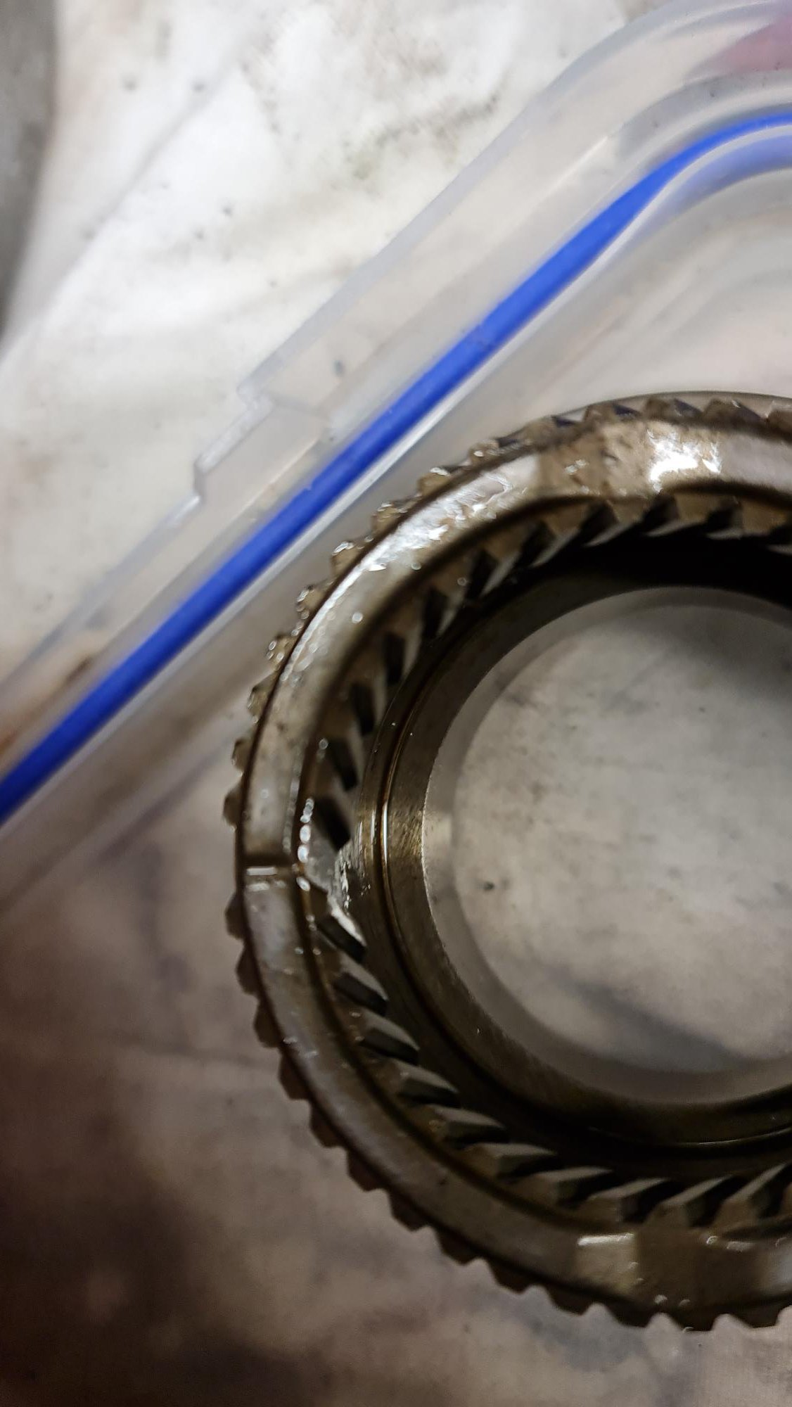
Yes, yes and yes This weekend has been both warm and no wind, this allowed white paint to go down on Saturday followed by the red on Sunday. Still have black around the window frames and forgot to sand the bonnet so it still needs a final coat..... Important part is the main body has been completed before winter, having the car running this summer should be possible. Overall quality has come up pretty good, a couple of runs/sags that will need cleaning up, very satisfied with how crisp the masking came out, only a few small bleeds to clean up, nothing that can't be touched up later down the track. I can now start refitting parts, next goal is to get it rolling again.
2 points
-
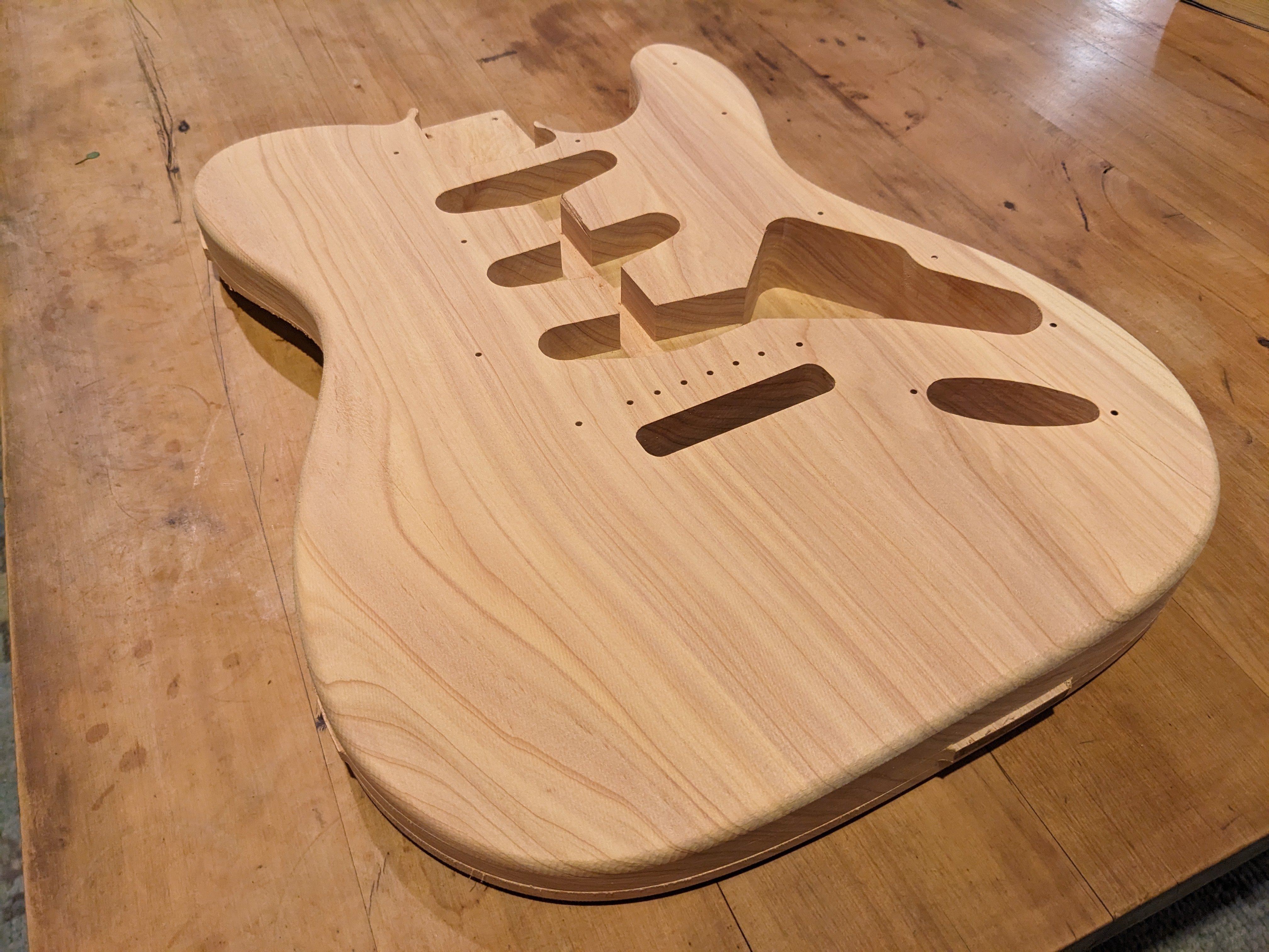
Also to complete a trifecta of side projects, I thought I'd have another go at a guitar body, which I just finished up tonight. This has been done with the benefit of some accuracy improvements to the router and now knowing a shitload more about hsmworks programming. Thats a single big slab of macrocarpa, it has come up real nice. Still a wee bit of misalignment from when it gets flipped over. But it is only about 0.1mm, that will buff out easy as.
2 points
-
I got the rest painted on Saturday morning. Half sick and fully fumed out it was bloody hard to see what was happening but luckily it’s not all streaky, lol. Again, the ground coat went on fucking gravy, topcoat thick. I slapped some bumper paint on, spray bombed half of the trims + scuttle and grille.. they had faded from the3 year stint out in the sun. Number plates totally weren’t sprayed and sanded back. Also welded a stainless tailpipe on, visually made a big difference. still have to flat and buff it some time, tint the tail-lights & install the new rare spares outer door glass weather strips.. what’s left of the factory ones are as hard as plastic2 points
-
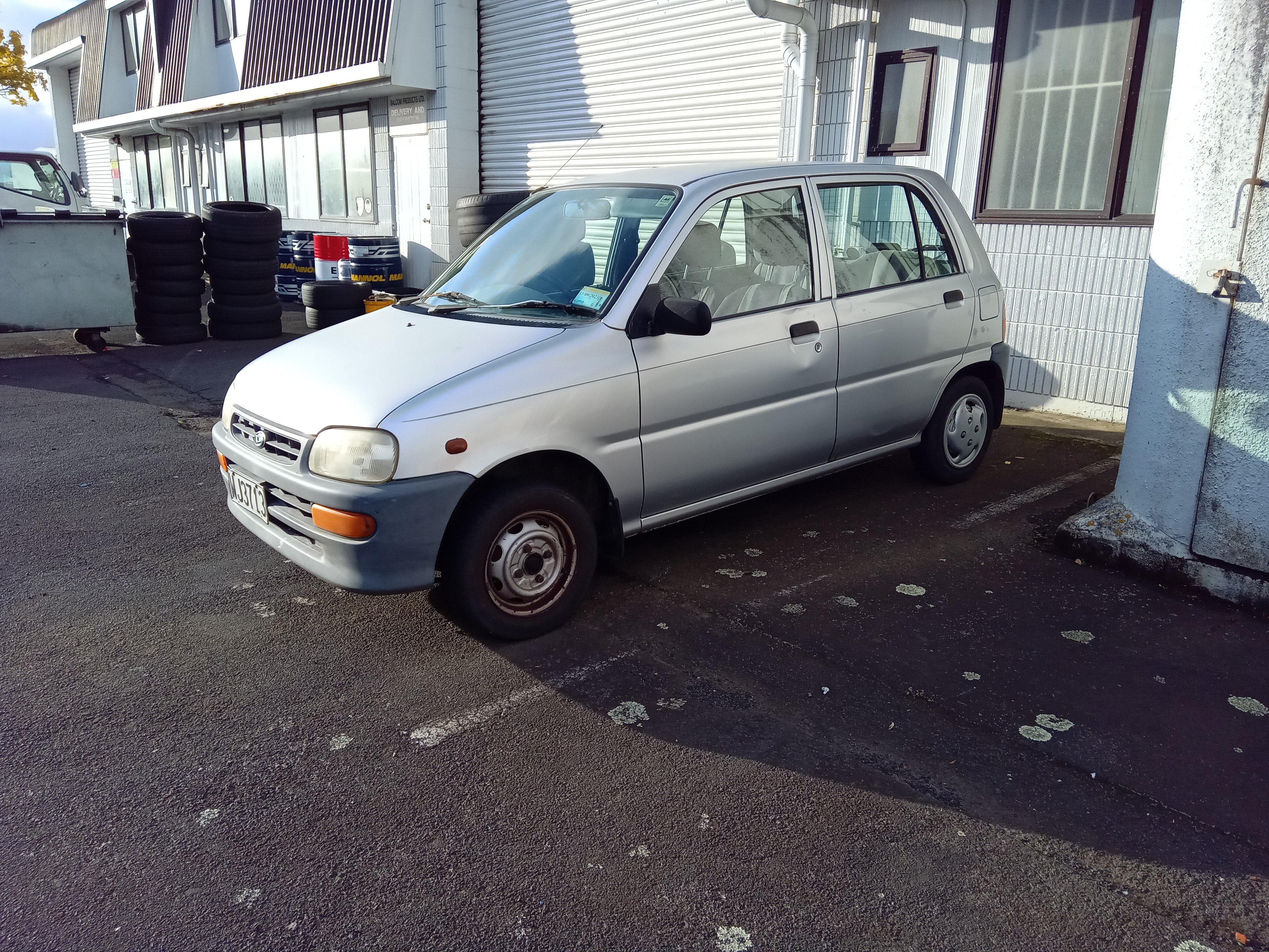
Was just minding my business and this follwed me home from @RX FORD's workshop I have no need for it but when has that ever stopped anyone? 660cc of twin cam carburetted 3 cylinder,transferring all its fury through an auto gearbox. It actually goes better than id expected it would,and despite being comically small,it has plenty of interior room even for a generously proportioned gentleman such as myself im not sure what ill do with it but ill tidy a few things up,get a wof and maybe some slam/wheels. My daughter has claimed it already, shes 11 so a way off needing a car but i found a big empty carpark and she had a driving lesson
2 points
-
Same same, starter wiring, single wire to the fuel cut off. Plus peripheral stuff like glow plugs and associated relays. Also I have a good short block here if you can find a head and ancilliaries, but I guess a complete engine would be better.1 point
-
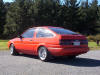
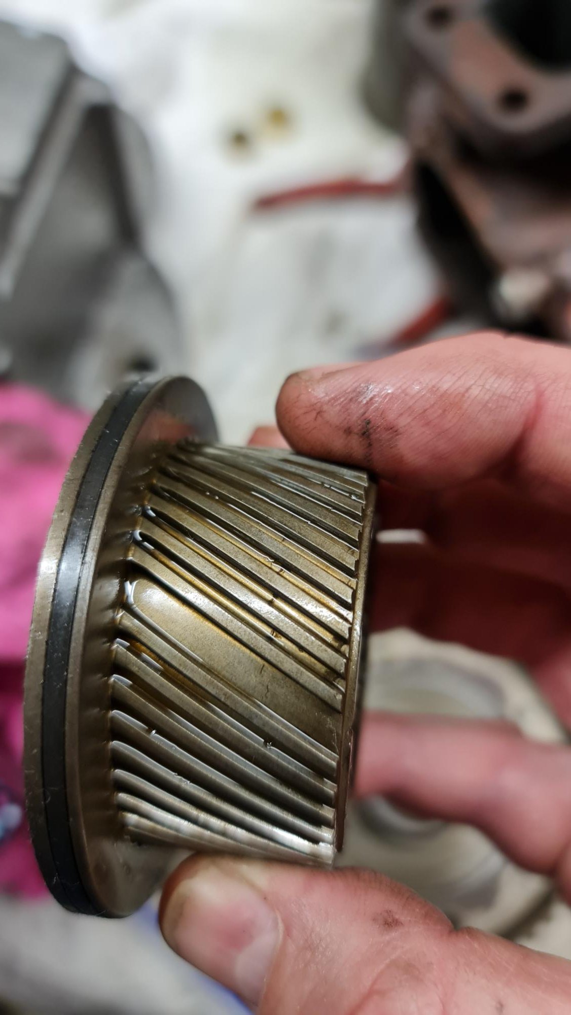
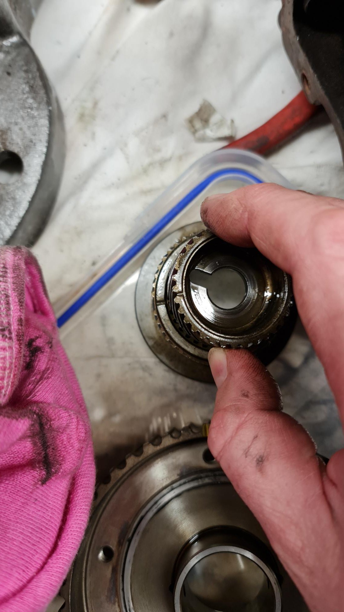
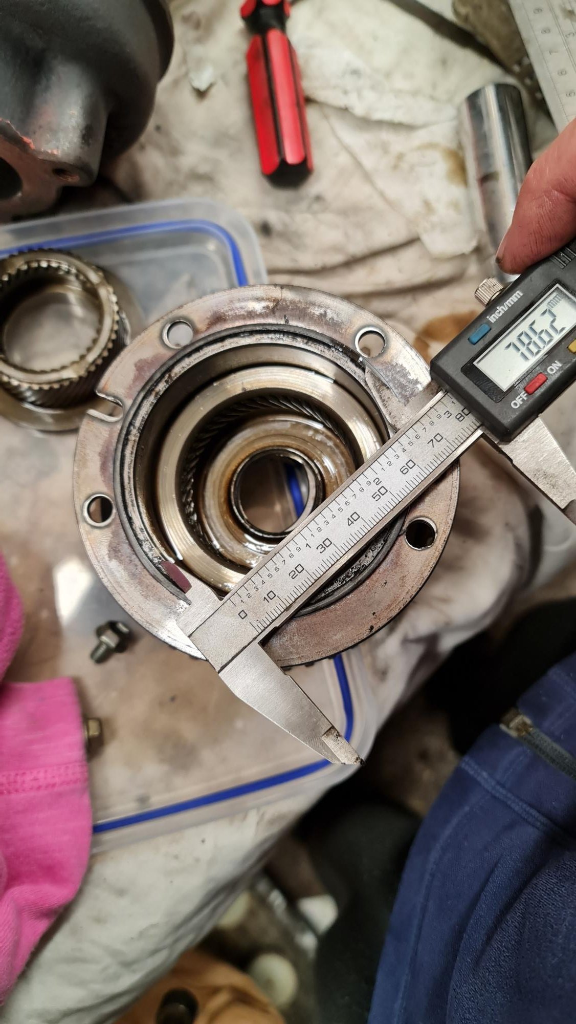
Remembered a while ago that I needed to replace the o-ring in the VVti pulley. Toyota don't sell the o-ring, only a complete pulley. I thought surely it can't be that hard to find a suitable one. There are a few people that sell nice Viton o-rings specifically for this but at $20 USD for the o-ring plus $40 to $160 postage (wtf 165??) I wanted to try source locally. Golbey's in Aus sell one, but didn't specify if Viton or not. I asked and they confirmed it is only Nitrile, which isn't really suitable since it appear to only handle 100deg C. When Viton is 200ish. Went to one of the local o-ring places, bought one that looked like it would work. Turned out to be slightly too thick. Then I found Seal Innovations' website has a search function where you can specify the ID and the width/thickness of the o-ring, plus the material. Found one that I thought would be perfect but it is out of stock, a week later they said it was now in the country but still being processed then it'll be sent to Wellington. Long story short I picked it up yesterday and it looks to be a perfect fit. That held me up for about 3 weeks...I really should have looked into it earlier. Here is the very perished and flat o-ring: VVti pulley has locating grooves for all three gears, plus a match mark so is simple enough to put back together, just remember to mark the timing beforehand.
1 point
-
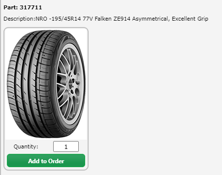
It has been a while since I've been here but thought I'd give you a tyre size update. Falken currently has 195/45R14 ZE914's available in NZ. Legal up to 7.5" wide rim. These are classed as a NRO (no re-order) so once they're sold they're no longer available, roughly 150 in NZ currently. Depending on who you know, they're roughly $150-$200 each.
1 point
-
The TS3 is waaaay too wide. As is the daimler V8. What will fit so far that I have in stock: Isuzu 4b diesel (with some mods) Holden 202 Essex V6 Slight issue is that the truck cert guy wants to know the GVM as he thinks it is for a car cert person. I sent him the sales brochures I had and a guess. See what he says I guess.1 point
-
If you are dead set on deisel engine probably a straight 6 would be best. Land rover TDI is underpowered even in a disco, td42 would be good. My old work had a 1992 Isuzu forward, it was na but plenty powerful and super reliable, it's still in use. Not sure on engine model but would recommend.1 point
-
Not many projects are cool enough to do twice, this truck rules man looking forward to updates1 point
-
Yeah I didn't have much luck with Hylomar and coolant tbh. Used it on a thermostat housing and it leaked almost straight away (yet its doing a good job of sealing my cork sump gasket...). That threebond is the utter bees knees (its OE Mitsubishi too iirc), but I've also had pretty good luck with Permatex blue rtv (its what I ended up sealing the aforementioned thermostat housing with and it's mint).1 point
-
I use this on most things https://hylomar.com/en/universal-blue/ Can't say i've ever used copper coat on bolts like that. Not that say that you shouldn't, I just never have.1 point
-
Jamieson motors in Taranaki do both car and truck cert it would seem, as they are certing a friend's belts on a camper which is on cof.1 point
-
Take The Pog route with a TD421 point
-
Make a new Epoxy nub then very carefully and slowly drill and tap it use a cork gasket should out live you if you never gorilla it tight in future.1 point
-
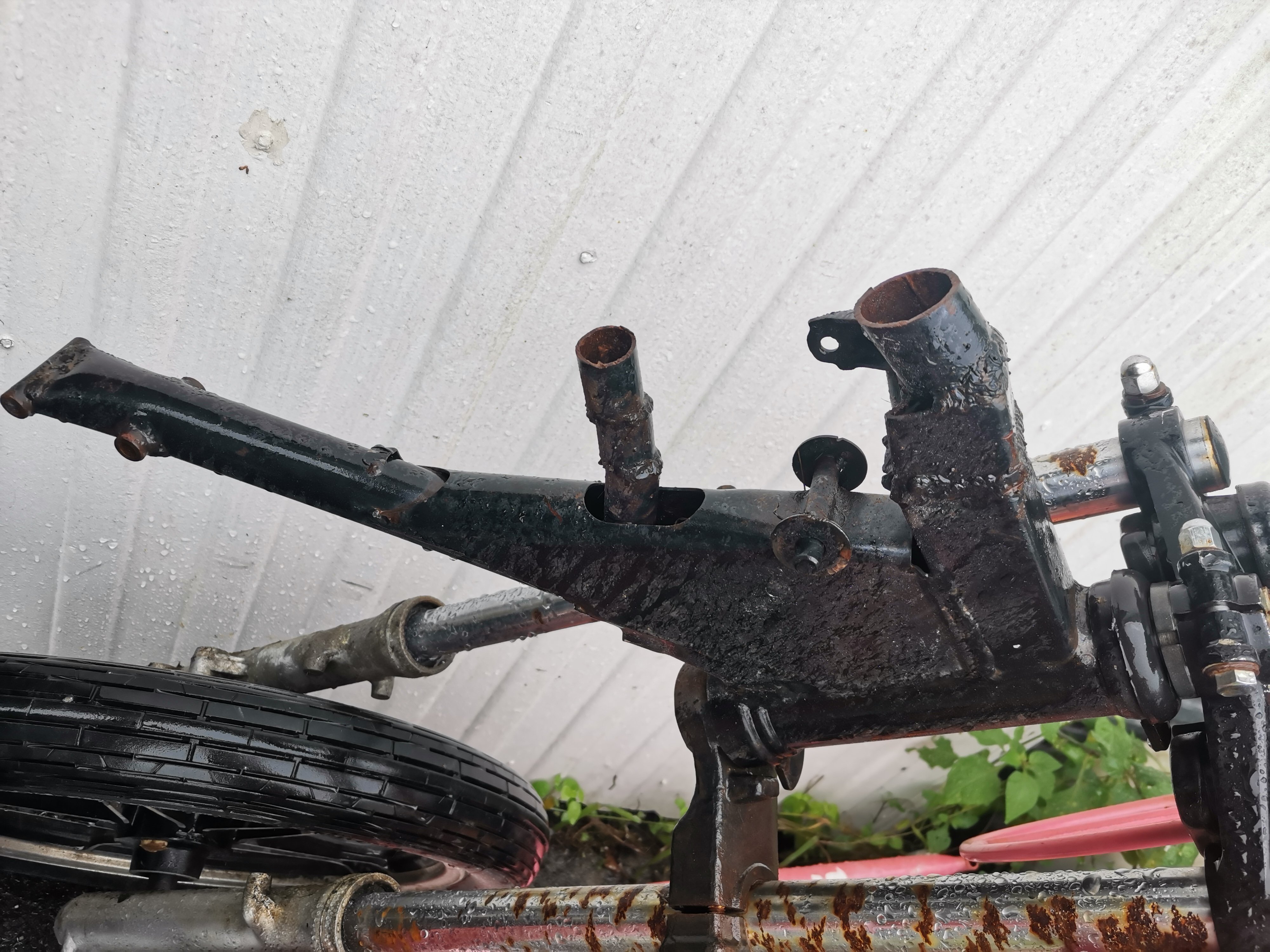
Oh yeah, the gn250 has a square frame I cut this abortion up so it would never see the road again
1 point
-
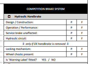
They are ok on a vehicle that have a Motorsport Authority Card, have to pass the MSNZ check.
1 point
-
It was a big day today... Still got a bit to do but like they say, good things take time. Thanks again to the amazing and beautiful souls @Seedy Al and @Goat for their hard work while I stood there and took photos. Without them and their assistance, I would have struggled to get it over the line. Oh yeah, it may have driven under its own power and I drove it across town to it at home for the first time in 7 years...1 point
-
Second I made another version of the stainless steel aeropress, this one should actually work when I try it out tomorrow morning. Its actually a bit taller than a standard one so I can make more coffee and spaz out just that bit more than I usually do.1 point
-
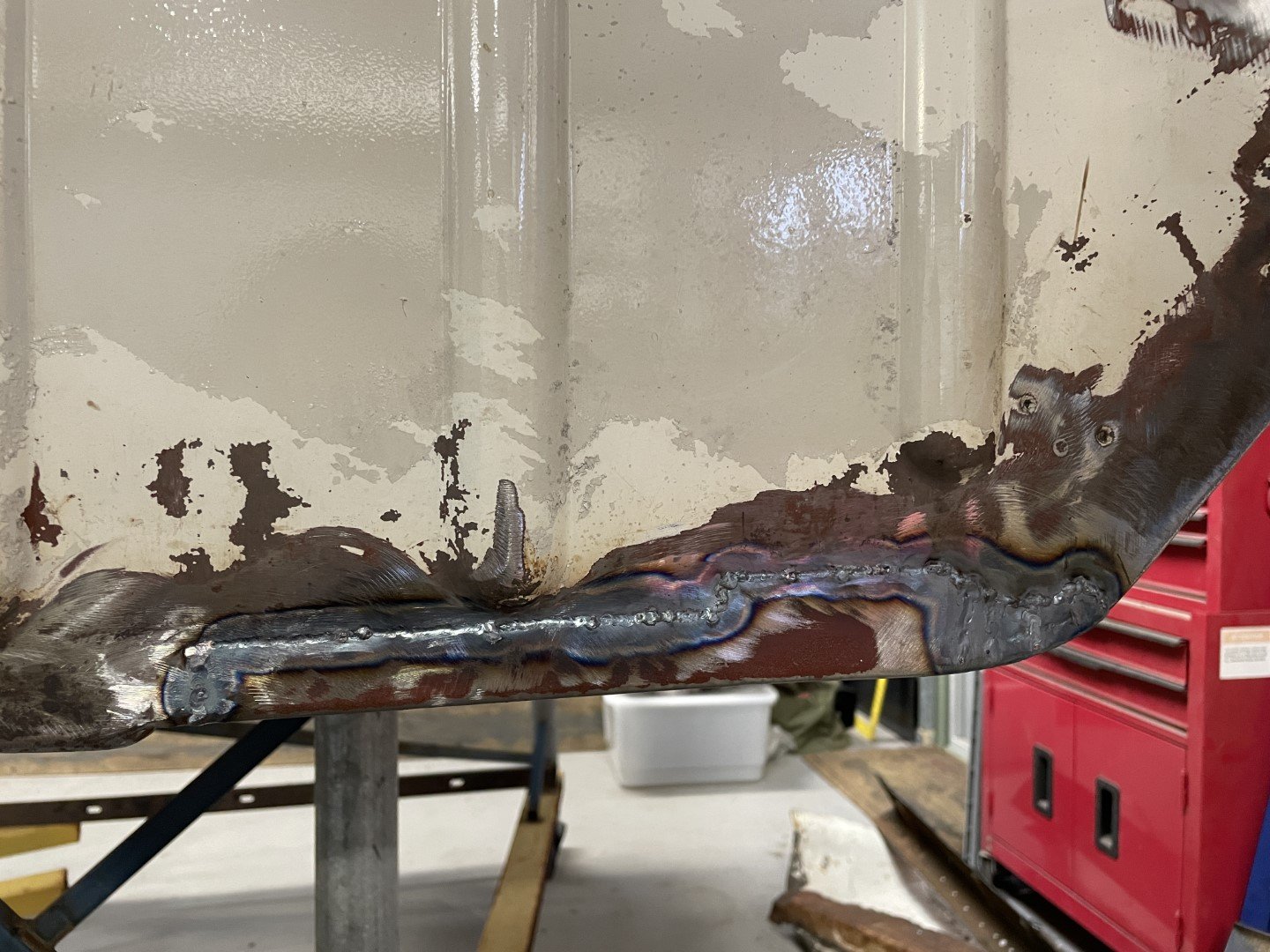
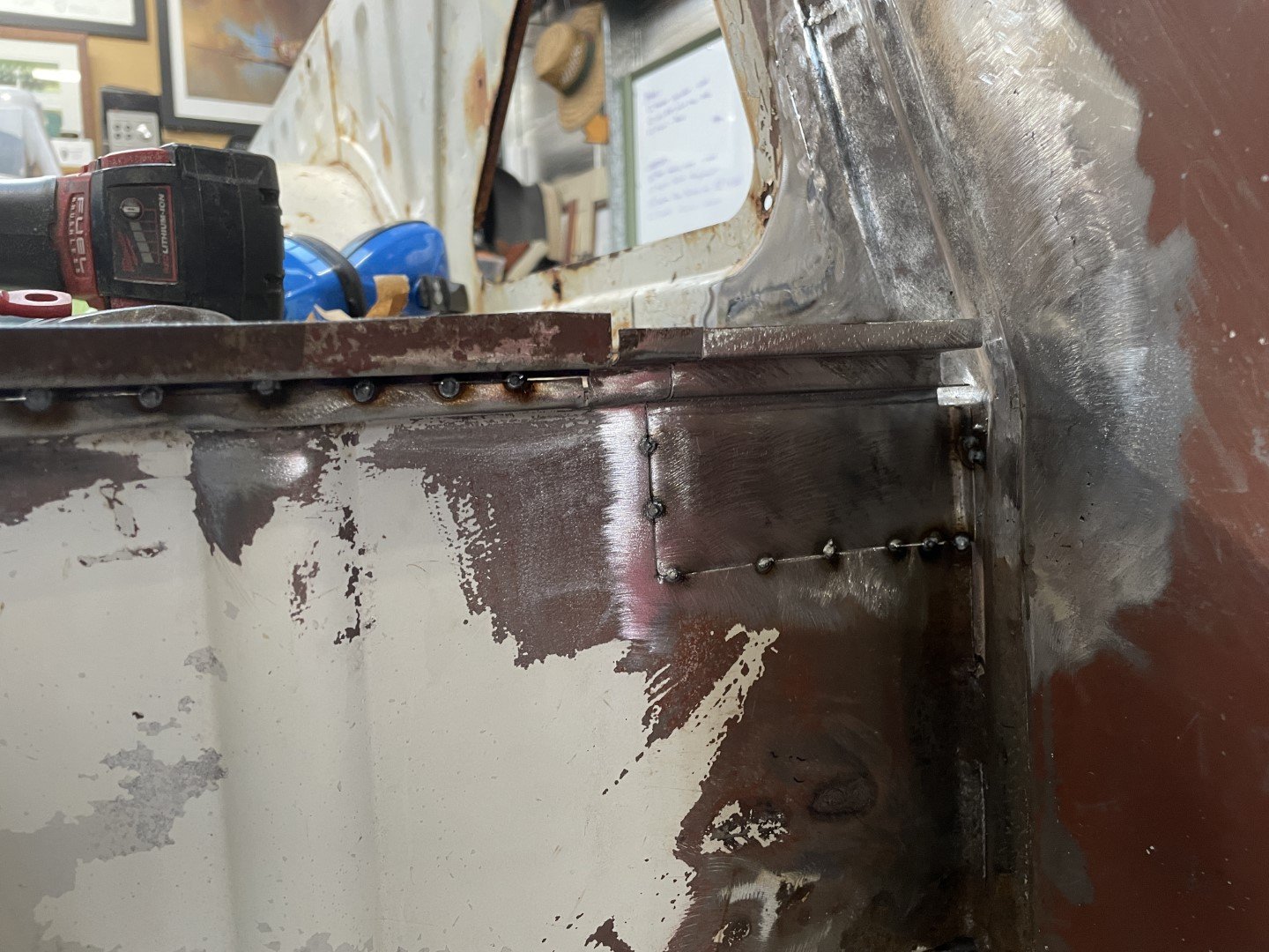
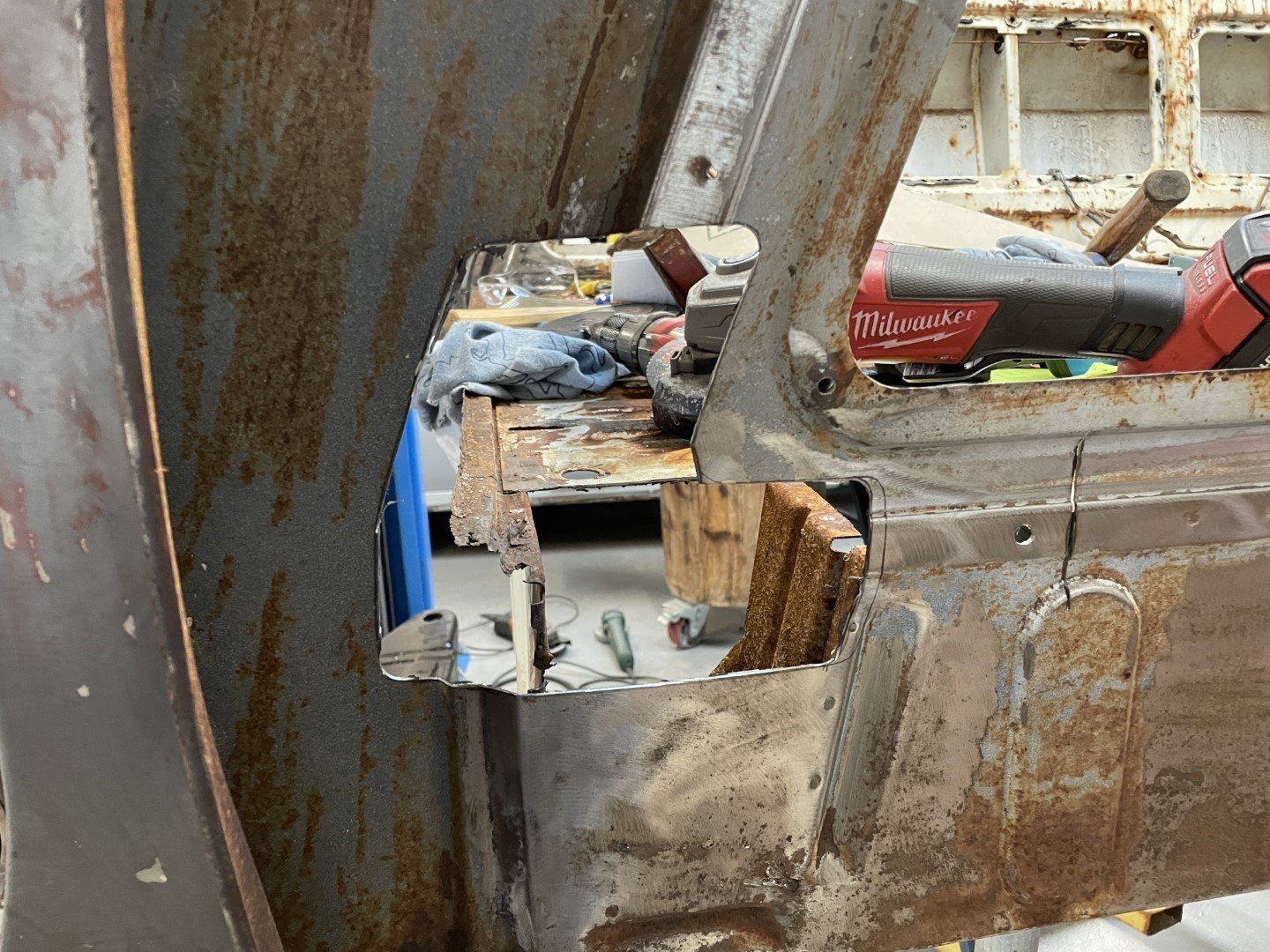
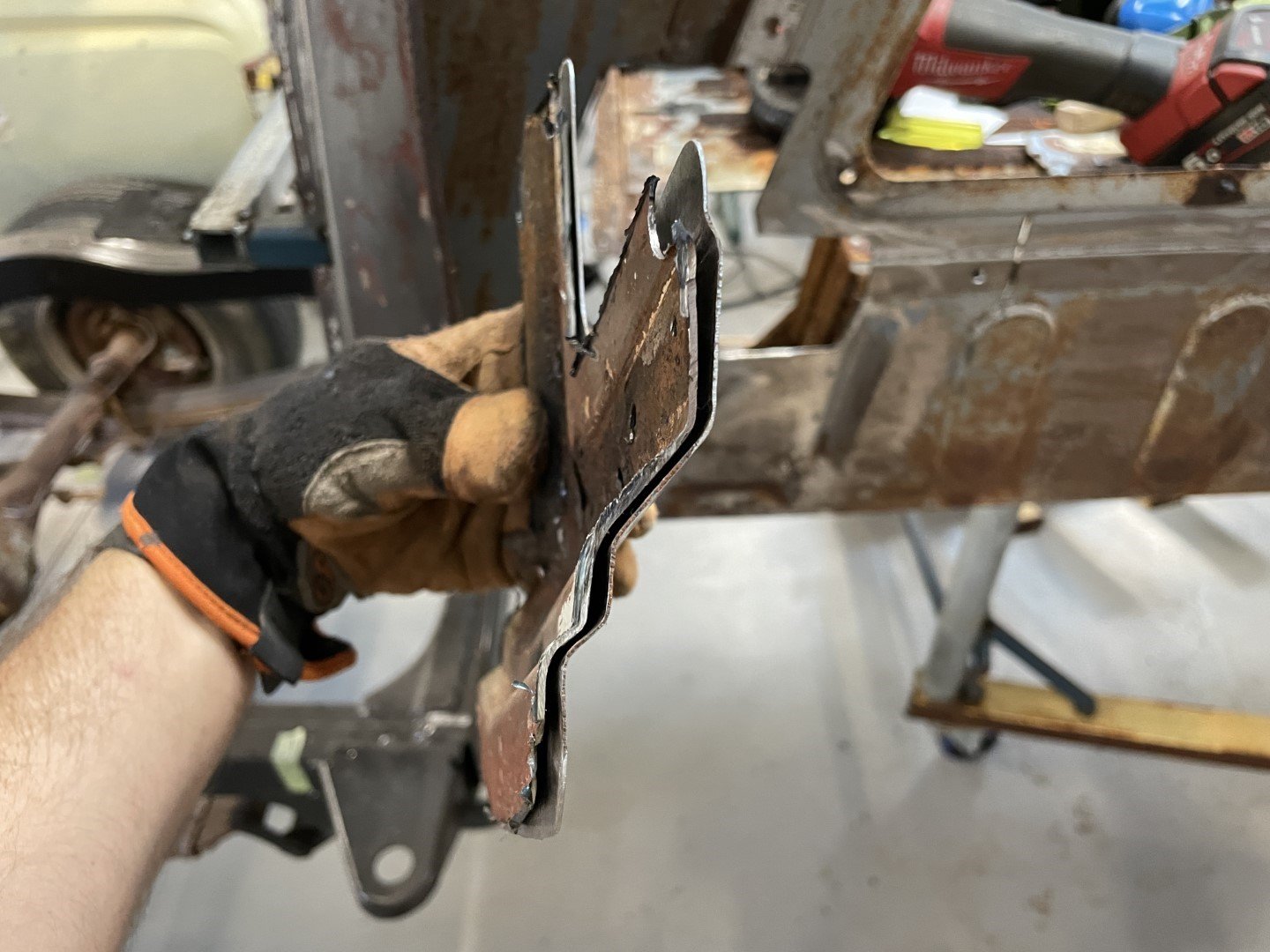
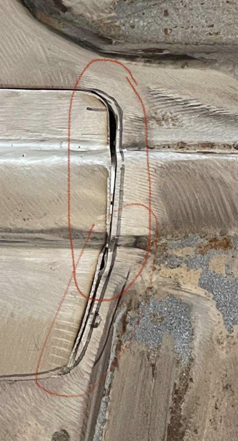
After getting that side spotted in, I moved back to the LH side to see how well I could get the first patch integrated. After I marked it out, I used the step drill to knock out the internal corners before attacking it with the 5" grinder. Old steel sat on new panel. Dropped the patch in after a little work tidying up the hole I'd made. Super happy with how the swage lines matched the original steel profile. In my haste to make it fit as the day drew to a close, I absolutely botched with fit on the back side - leaving a grand canyon to fill in with the welder. Figure it was a good enough time to pull up stumps for the day.
1 point
-
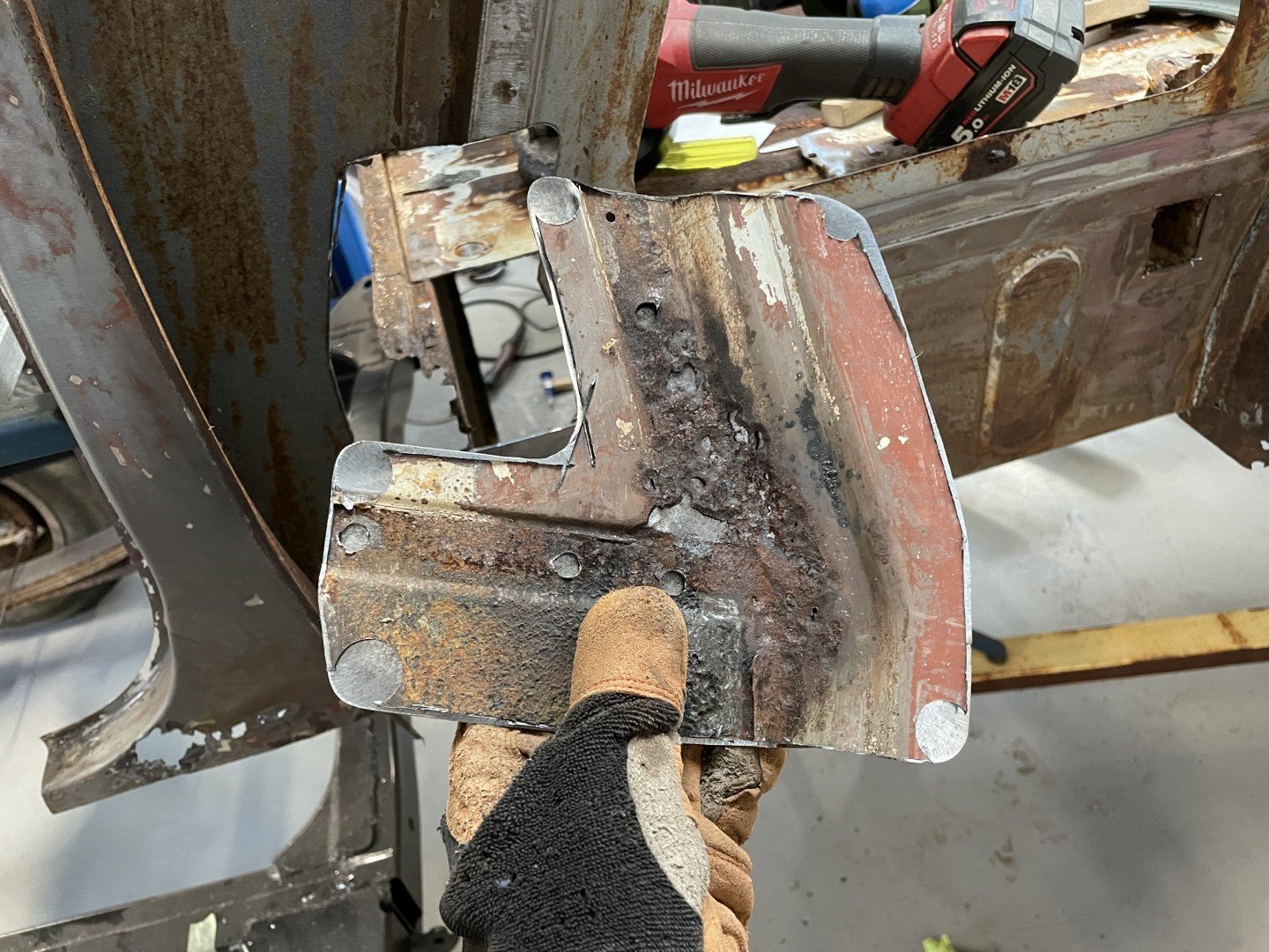
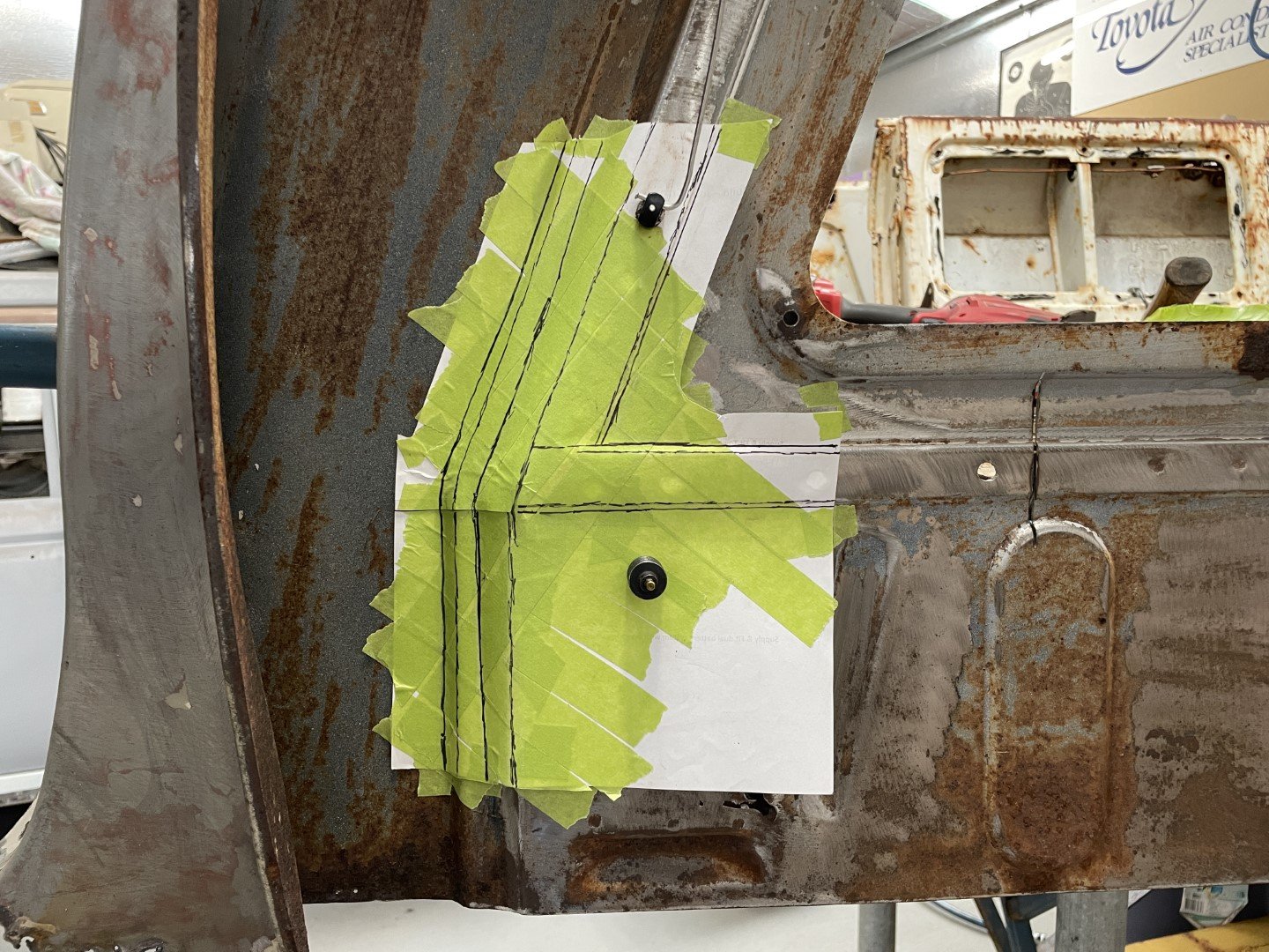
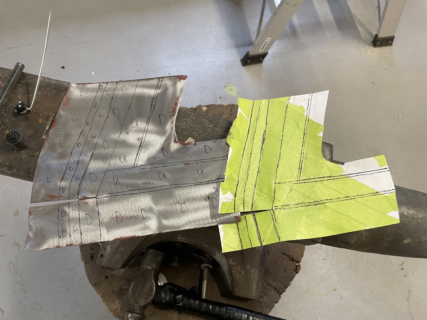
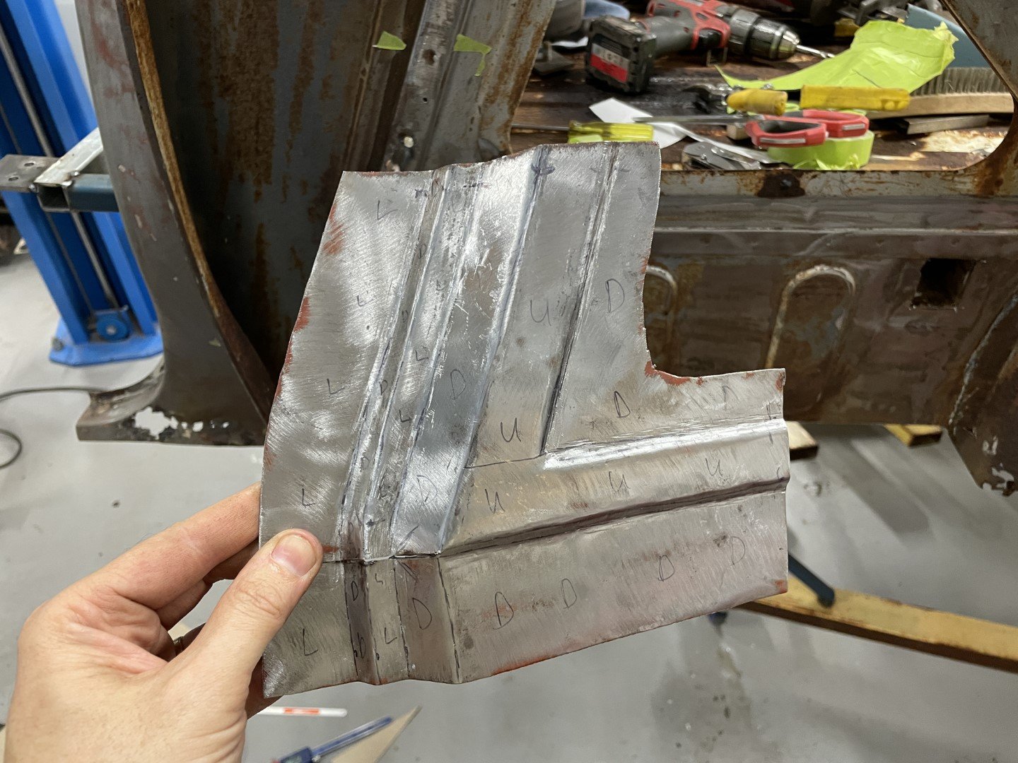
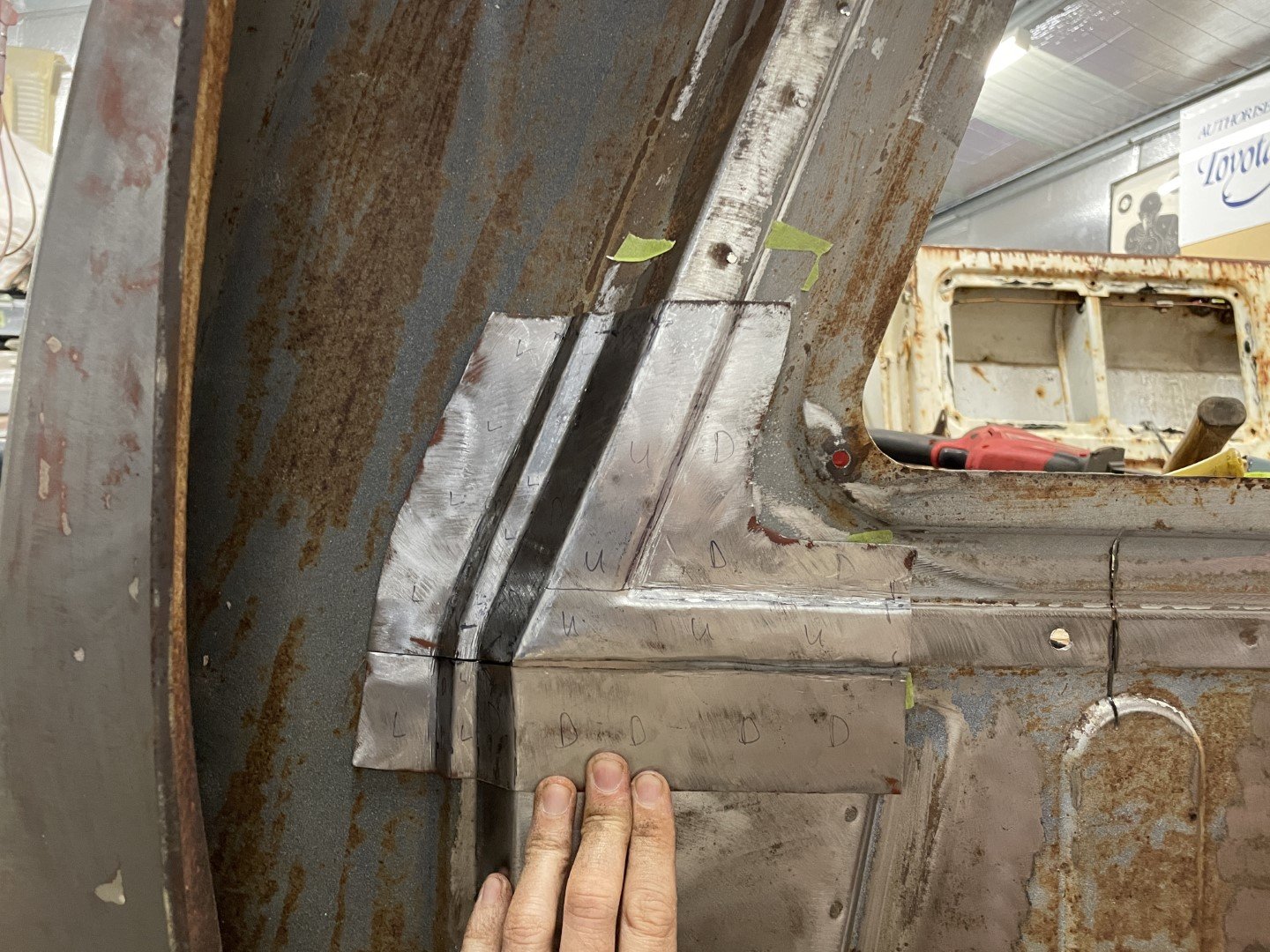
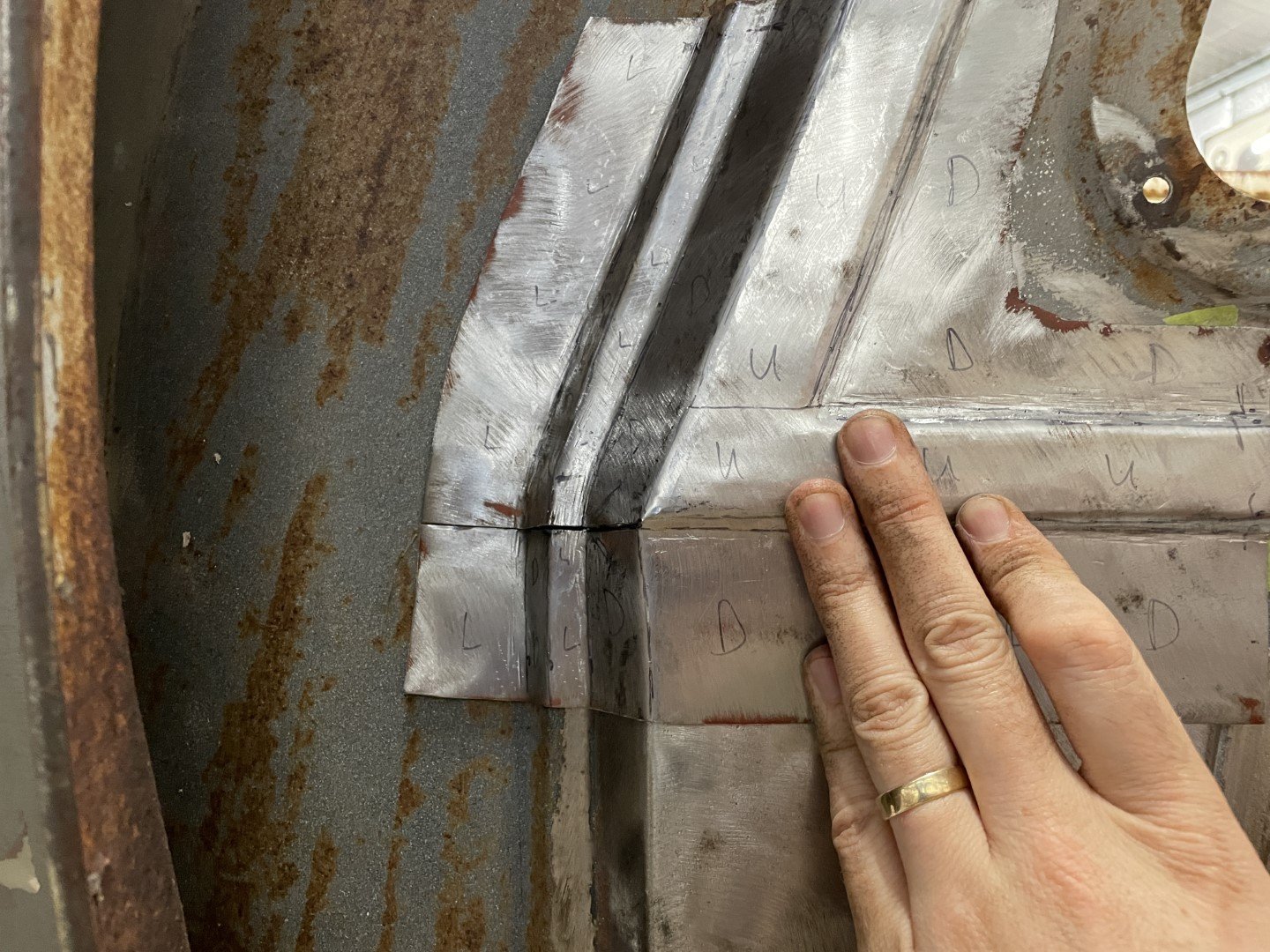
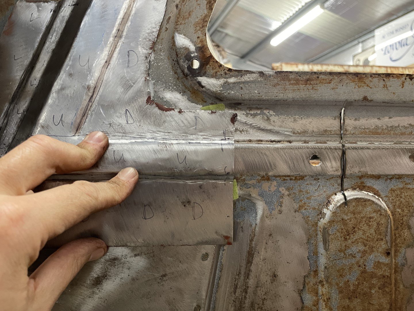
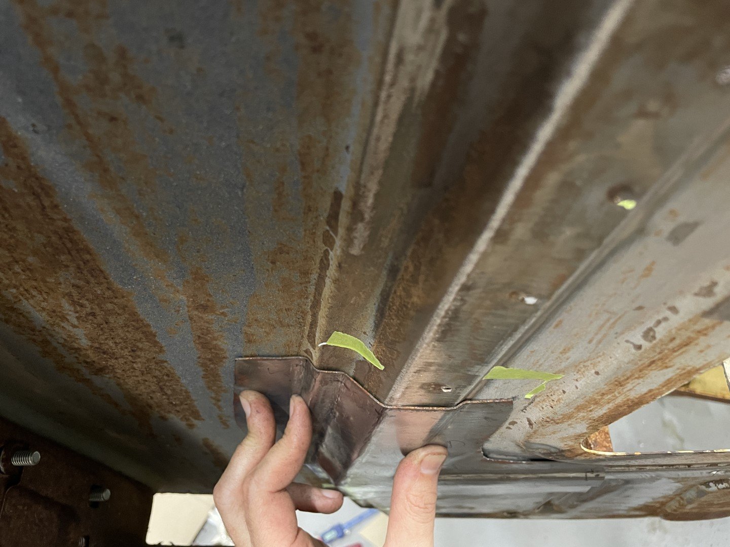
After multiple stoppages over the course of the day (required to stop kids from killing each other / wife losing her mind) I moved onto ACTUALLY trying to fix something. With good access to the inner structure now that the 1/4 panels weren't on the vehicle, I set about working out how to make a patch panel. Now, I've watched plenty of YouTube videos (Fitzee's Fabrications for example) and figured I would approach it in the manner Fitzee would - using multiple pieces welded together to make a complicated shape. After gathering up metal scraps, and establishing the best direction to attack the better of the two corners (P/S) - I came to the realization that I was in no mood for a shit load of cutting, welding and grinding. So I thought I would have a go at making a paper template that would pick up all of the important profiles and shapes that I could then go on to bash into a piece of metal. I put a piece of paper over the area I needed to copy, pressed and contoured it then put some tape over the top to give it some form. The masking tape did OK, but the template would have been much better if I'd had some of the reinforced plastic tape that the professionals use. Close enough to good enough, I checked it against the other (more fucked) side to make sure the upper rust holes were covered. I cut it down, then found some NOS sheet steel (piece recovered from the strip cut out of the sedan's roof panel) and then transferred the contour lines with a center punch. Intricate code on the sheet identified which profiles were UP, which ones were DOWN and which ones were LEVEL (which made total sense in my head at the time) Moved the anvil near the car and then proceeded to tap tap tap, bend and tweak until I ended up with something close. In all honesty - it didn't seem like a particularly difficult piece to make. Got lost in the back and forth between the body and the anvil until I had something that was pretty close. Just under an hours worth of hammering. Happy with the time investment. Relief cut needed some tweaking half way through hammering, but was pretty close to the money all things considered. The step / relief in the panel shown here does need some work, but when I take into consideration that this side won't ever be seen again - and the inside will have the tray floor pan spot welded up to it I'm calling it good enough. Pretty content with that fit. Stumps called, beer gathered and off to dinner.
1 point
-
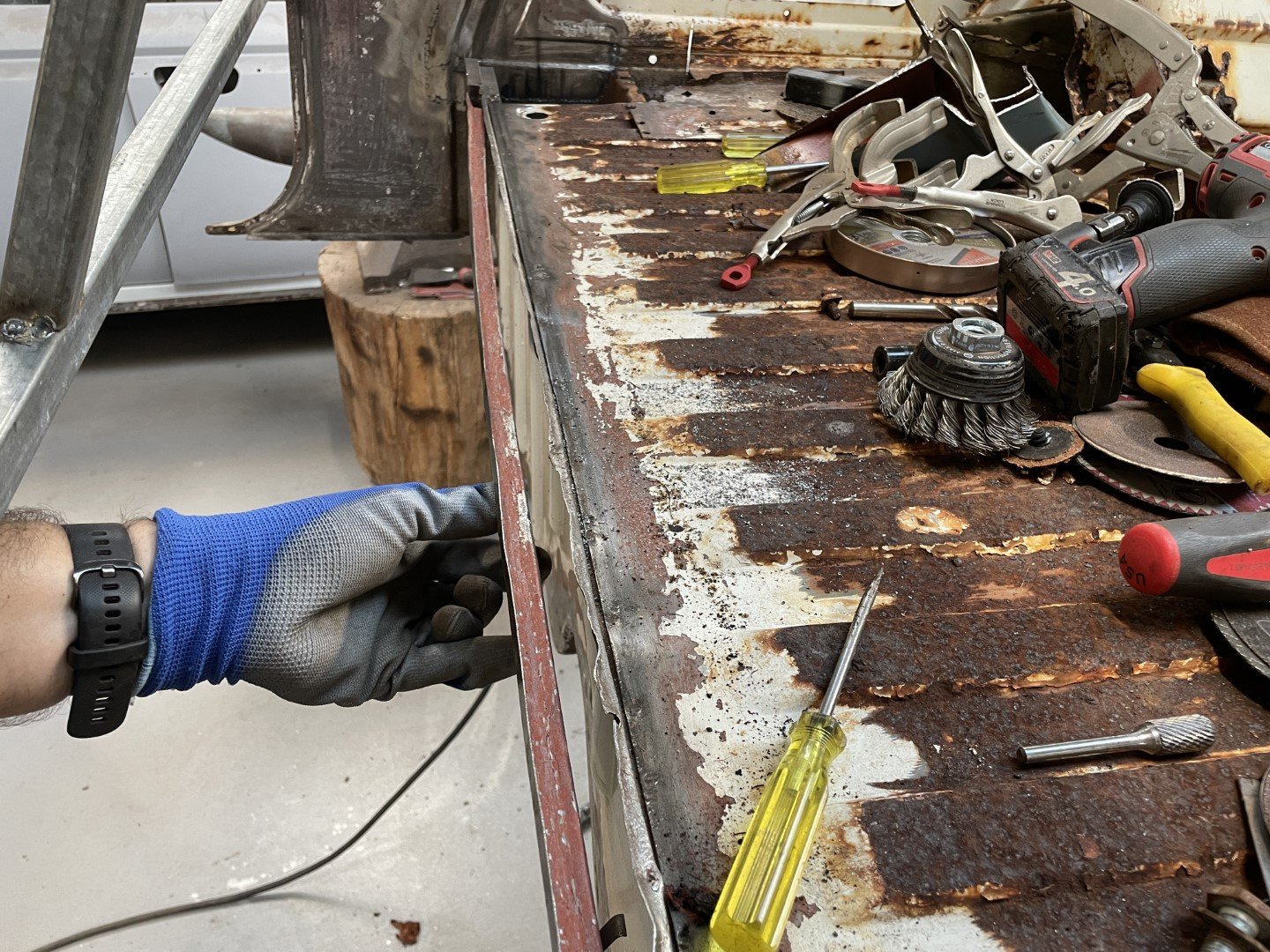
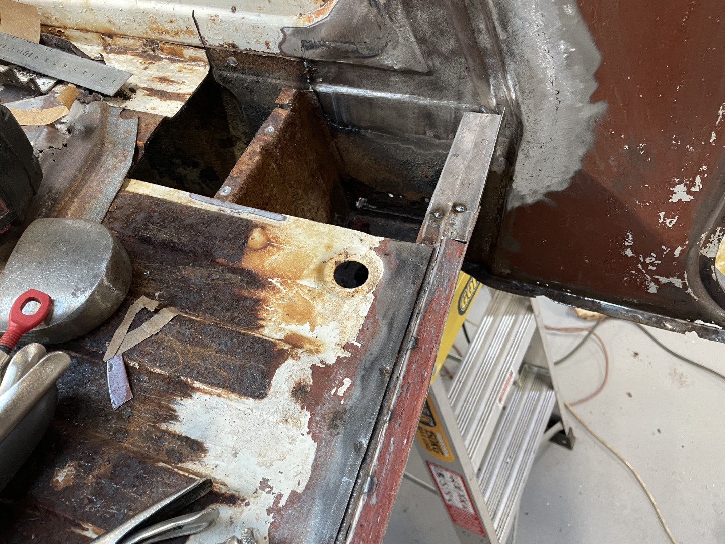
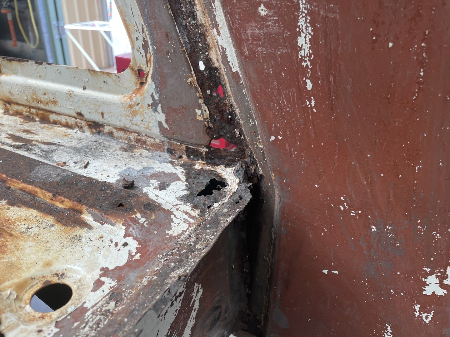
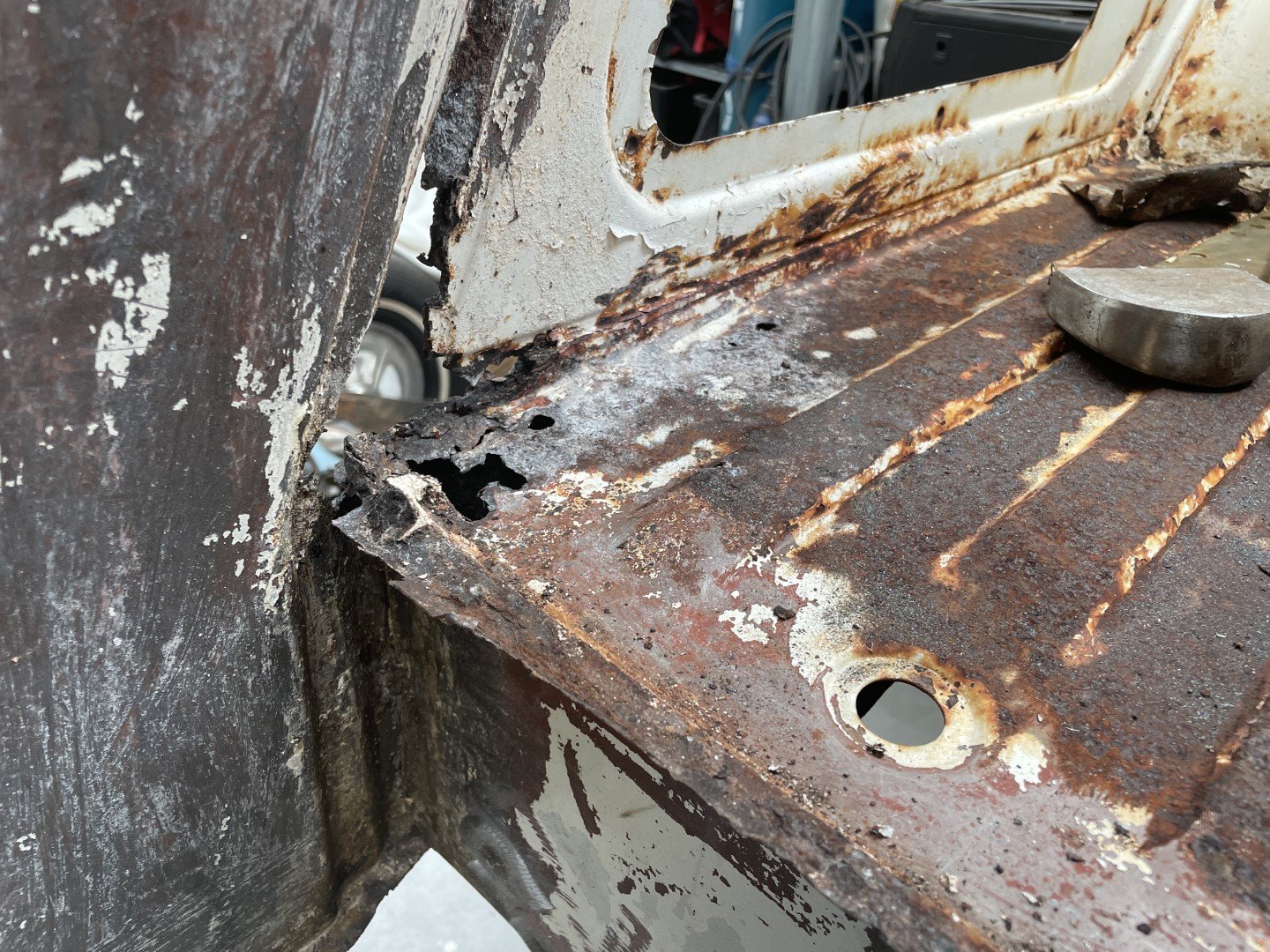
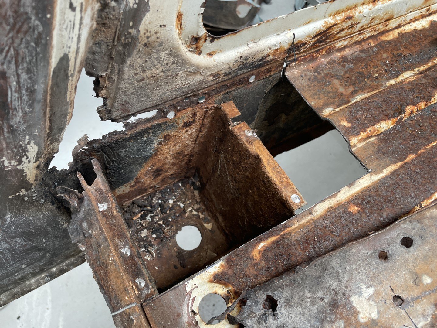
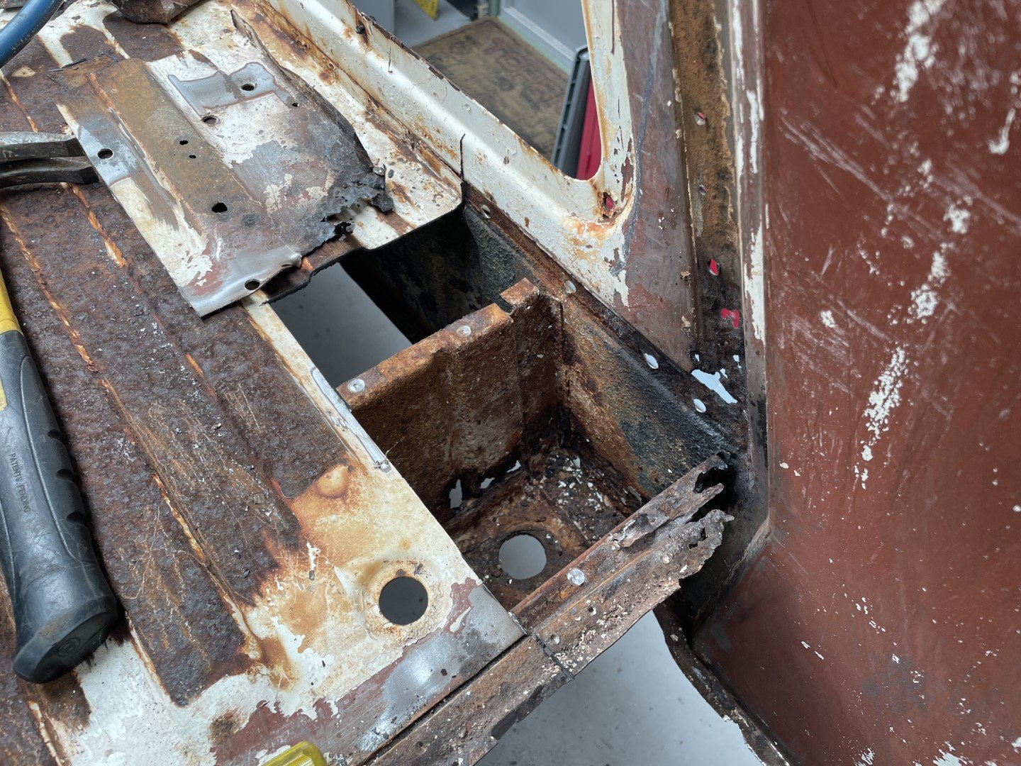
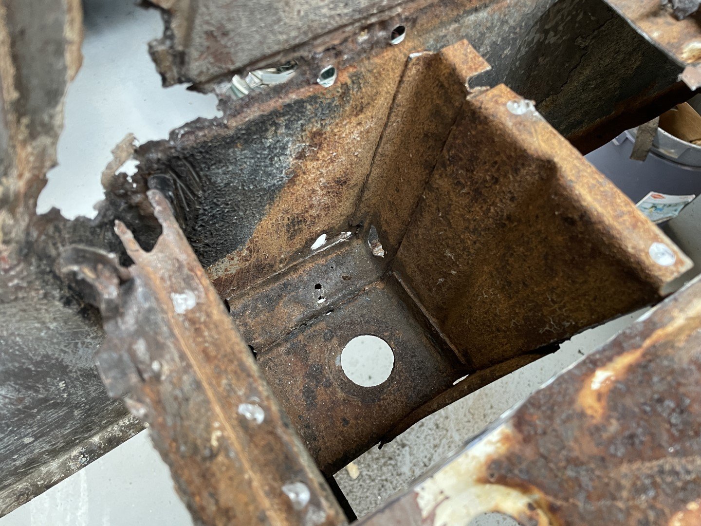
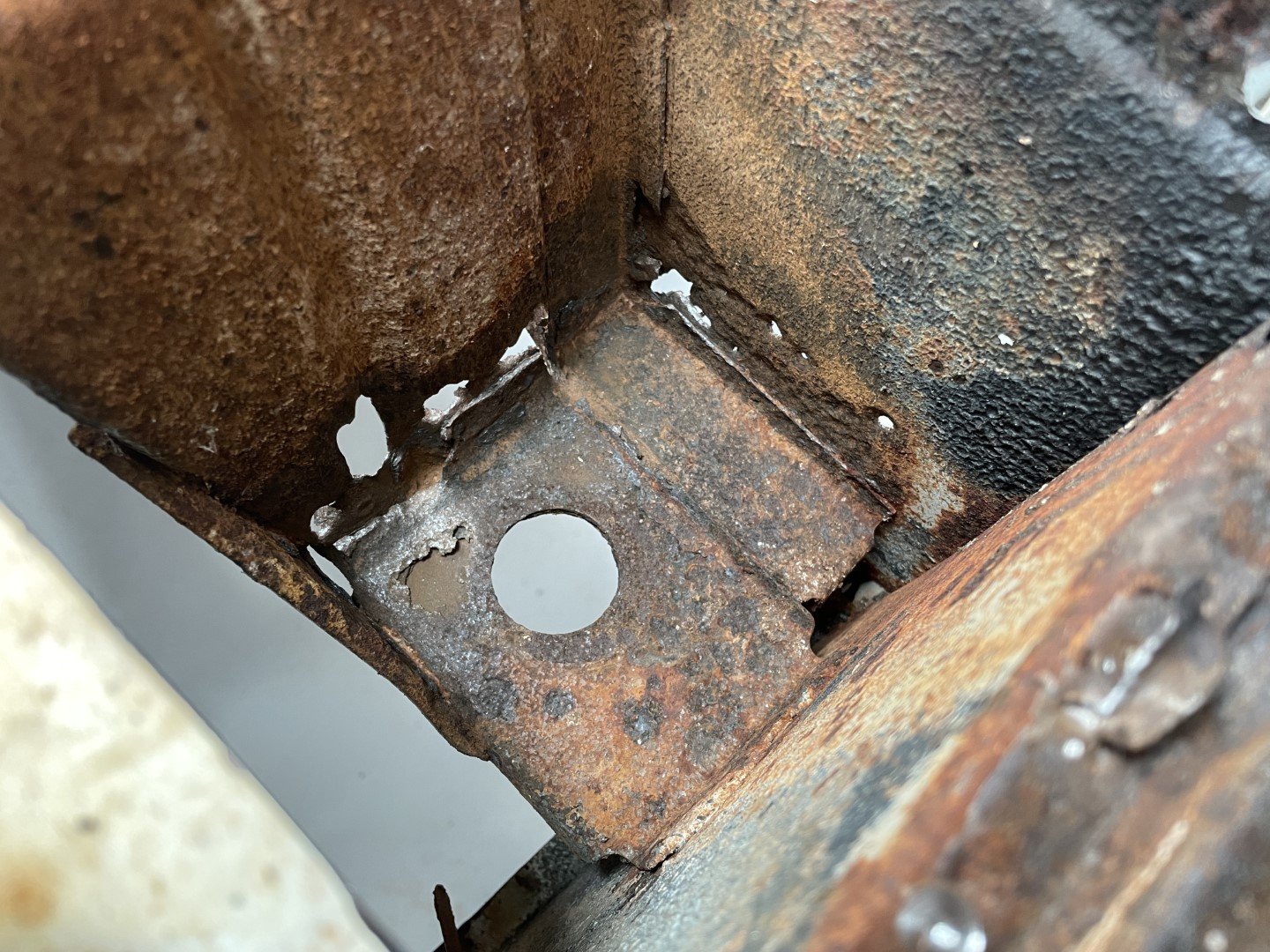
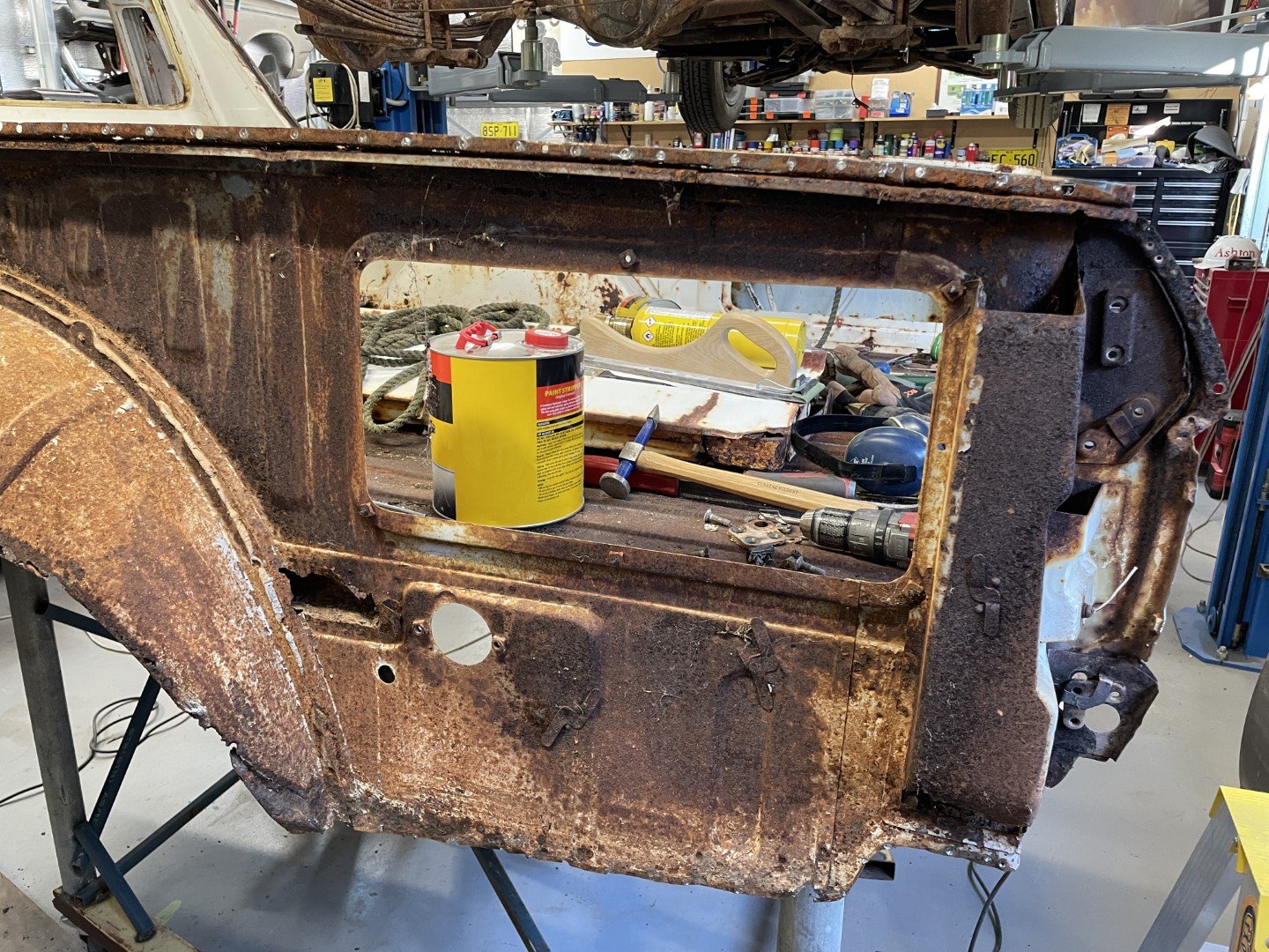
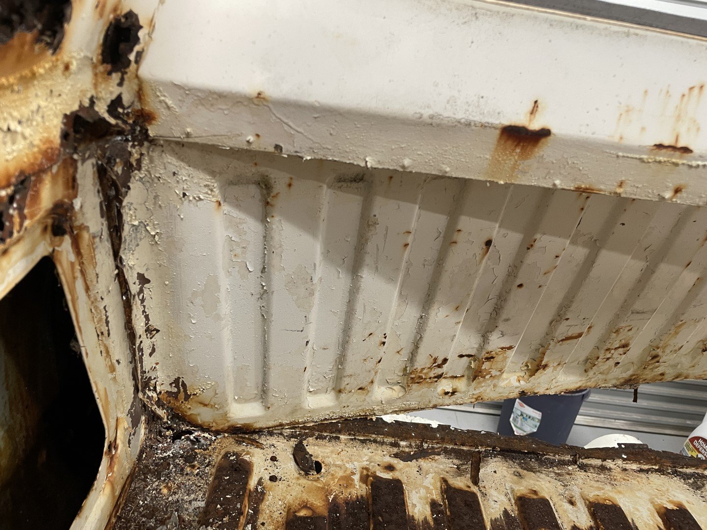
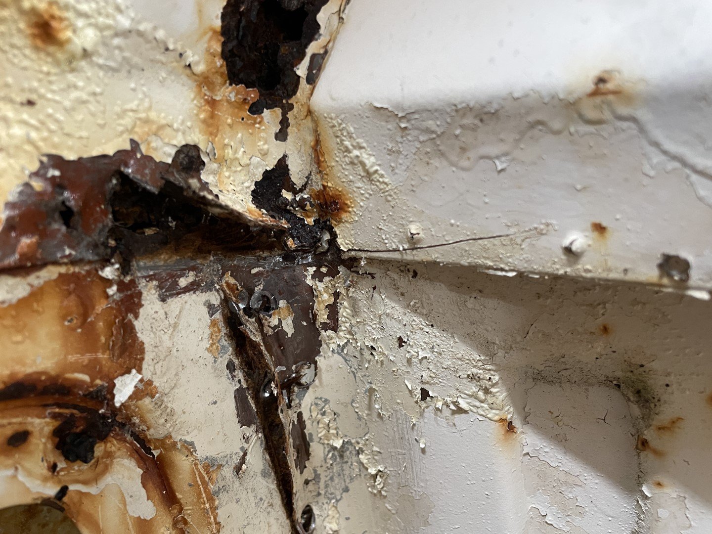
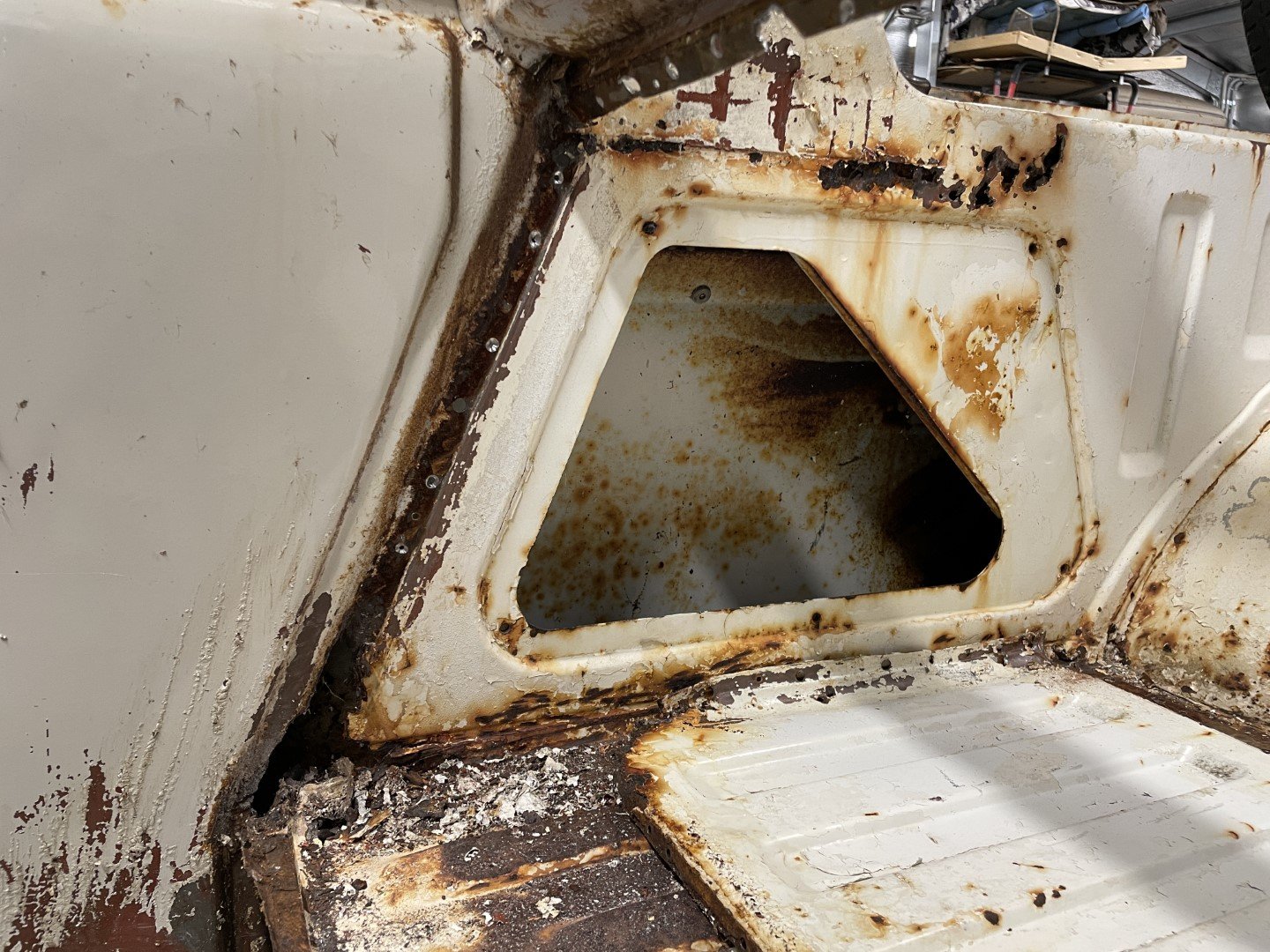
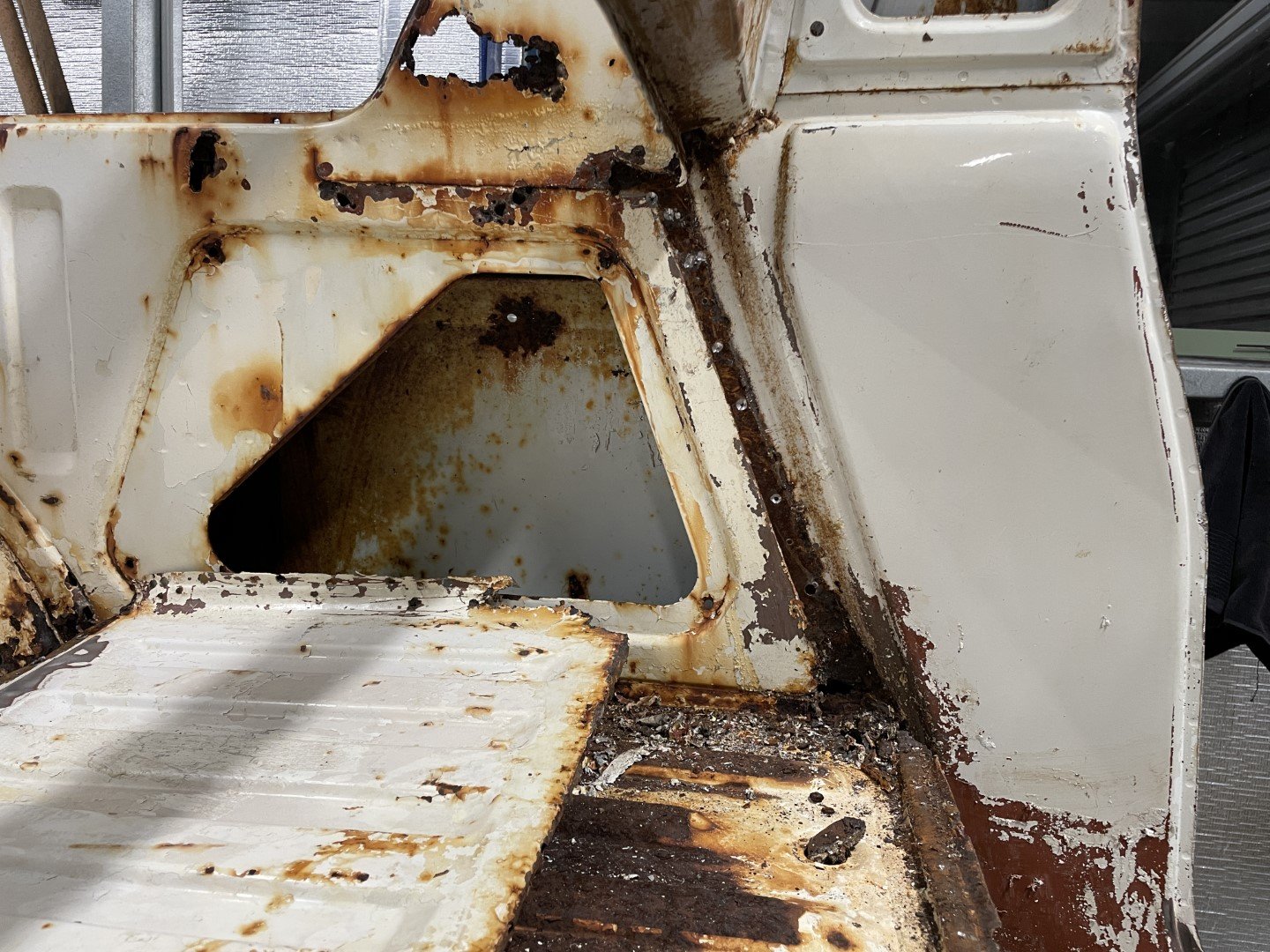
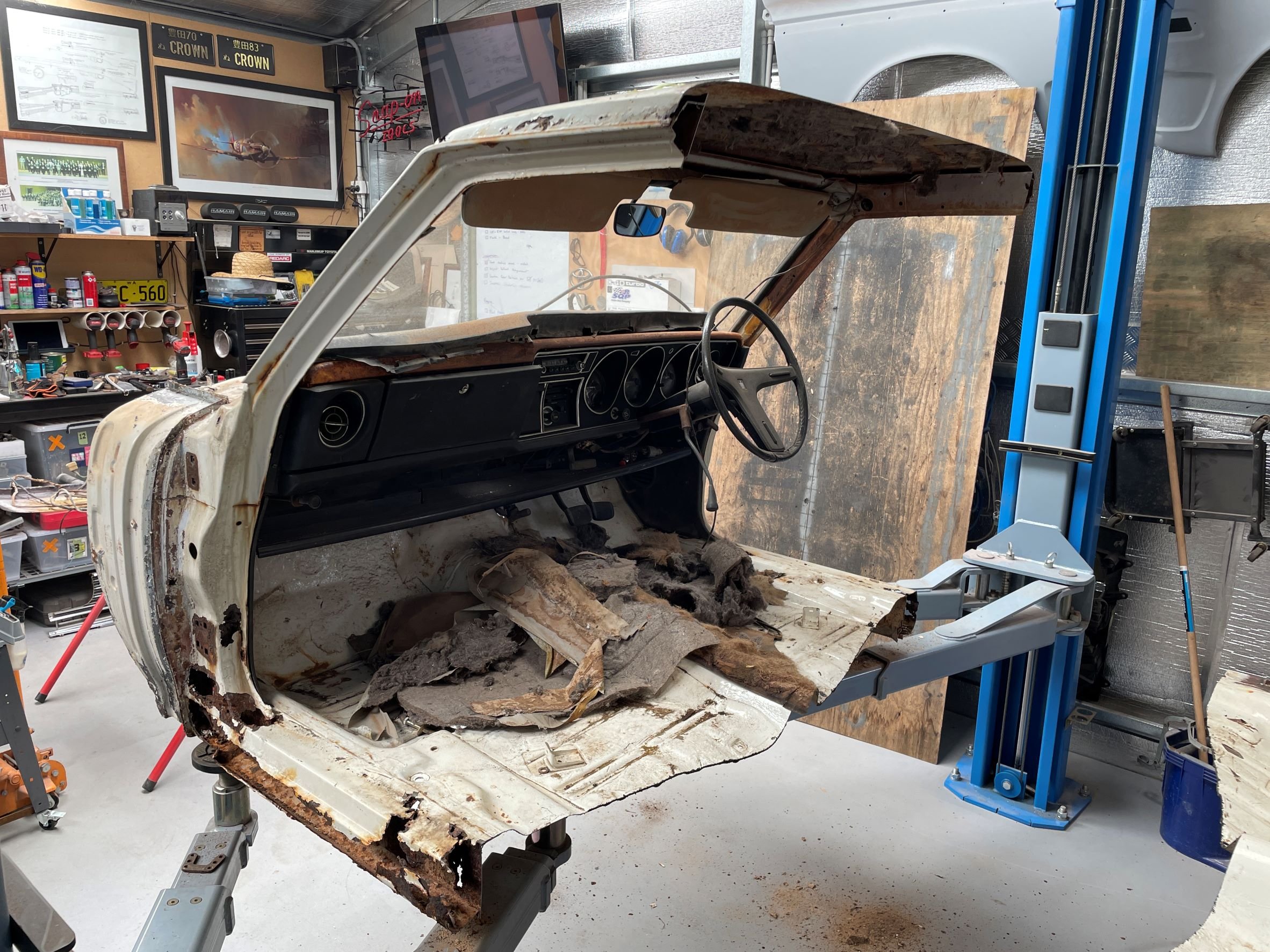
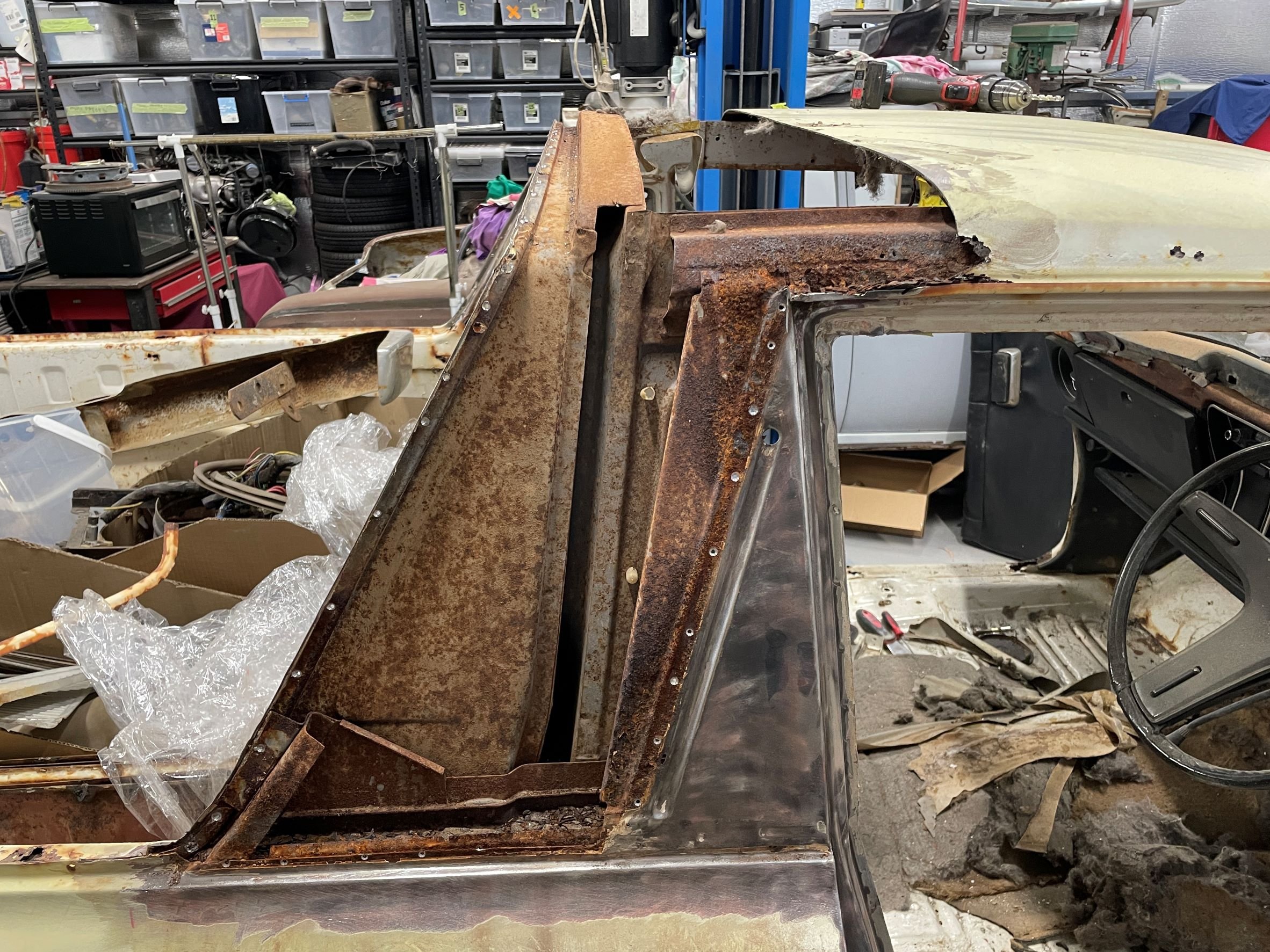
Found some time to get out into the shed today - which had me (once again) staring at the shell of the ute and contemplating the enormity of the project I'd taken on. Took my bitch pants off, put on some big boy pants and had at it. The front corners of the ute tray were giving me the most anxiety. I desperately want to stick the two halves together - but know deep down that avoiding these areas is just going to make my life harder later on when there's a floor pan in the way. The passenger side didn't look so bad - plenty of metal still in the corner (in the grand scheme of things). The Driver's side was considerably less good. Figured the best place to start was to cut the floor pan corners out. Found the D/S forward tray mount to be in reasonable condition considering I'd blasted 10kg of clay mud out of there earlier in the build. P/S forward tray mount was not as good - which was weird seeing as the upper section was in better condition. Dug the needle scaler out of the depths of the garden shed to see how good it would be at knocking the rust out of the hole. Did a pretty good job of identifying where the rust holes were. Yuck.
1 point
-
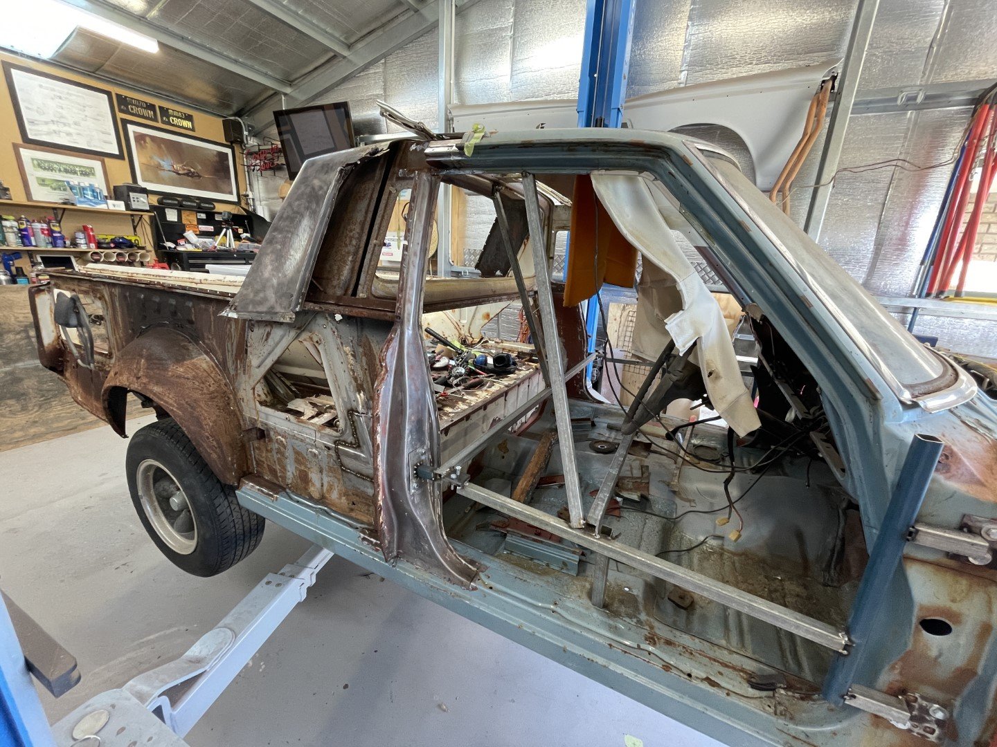
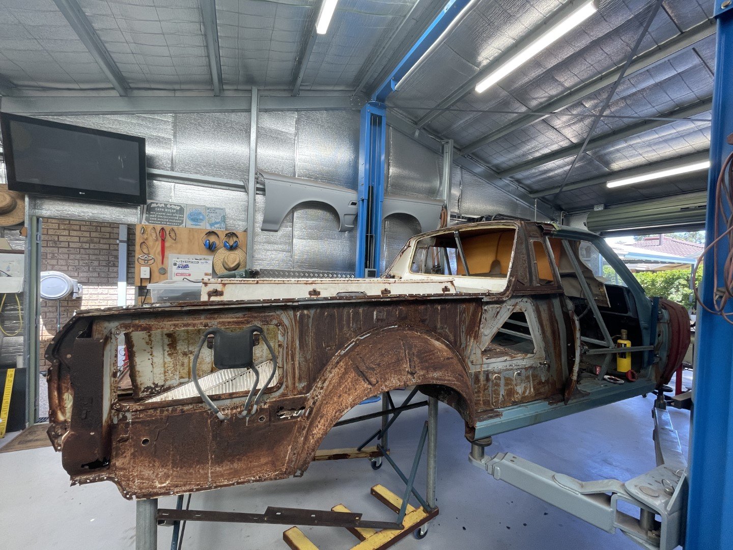
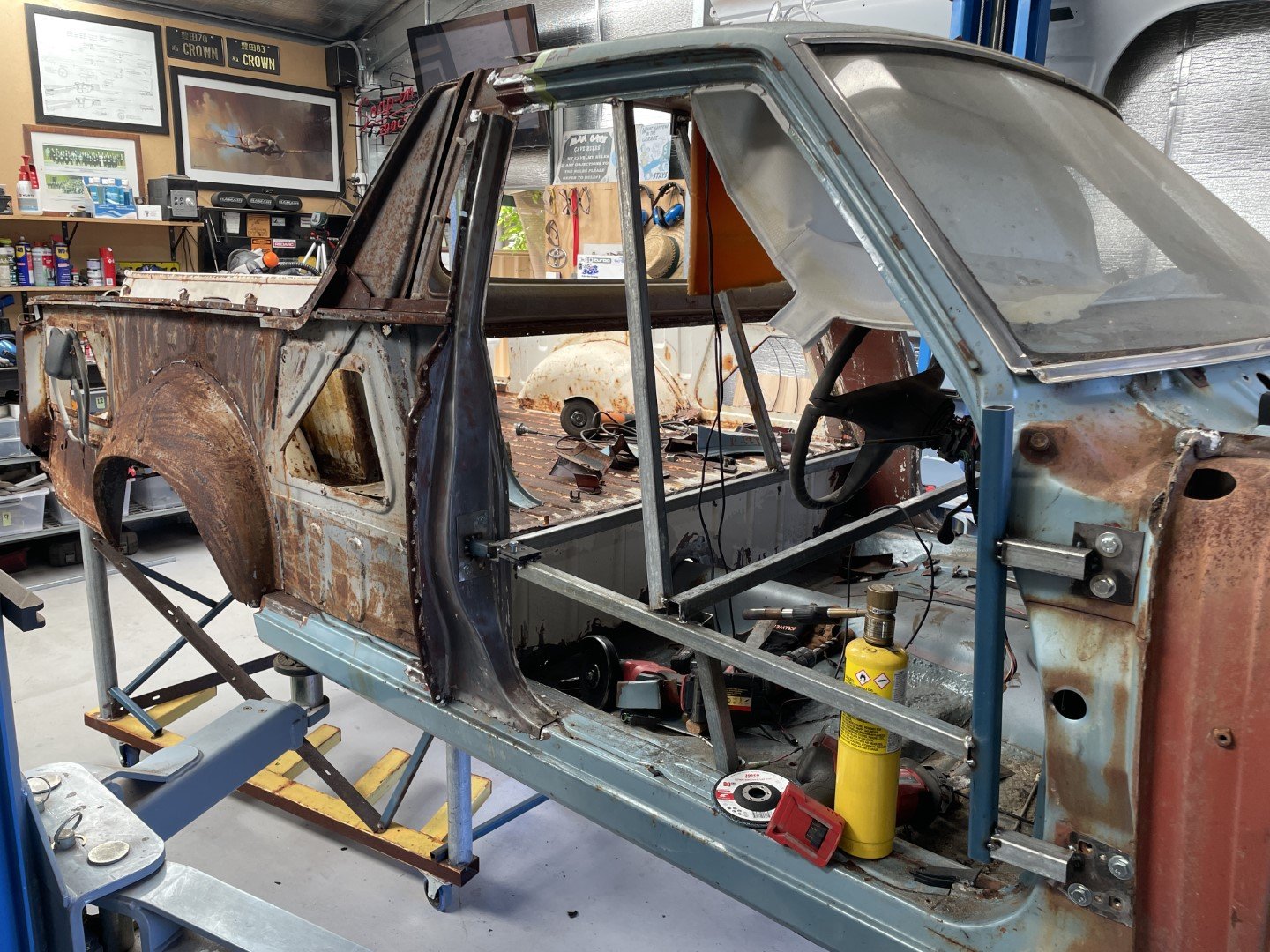
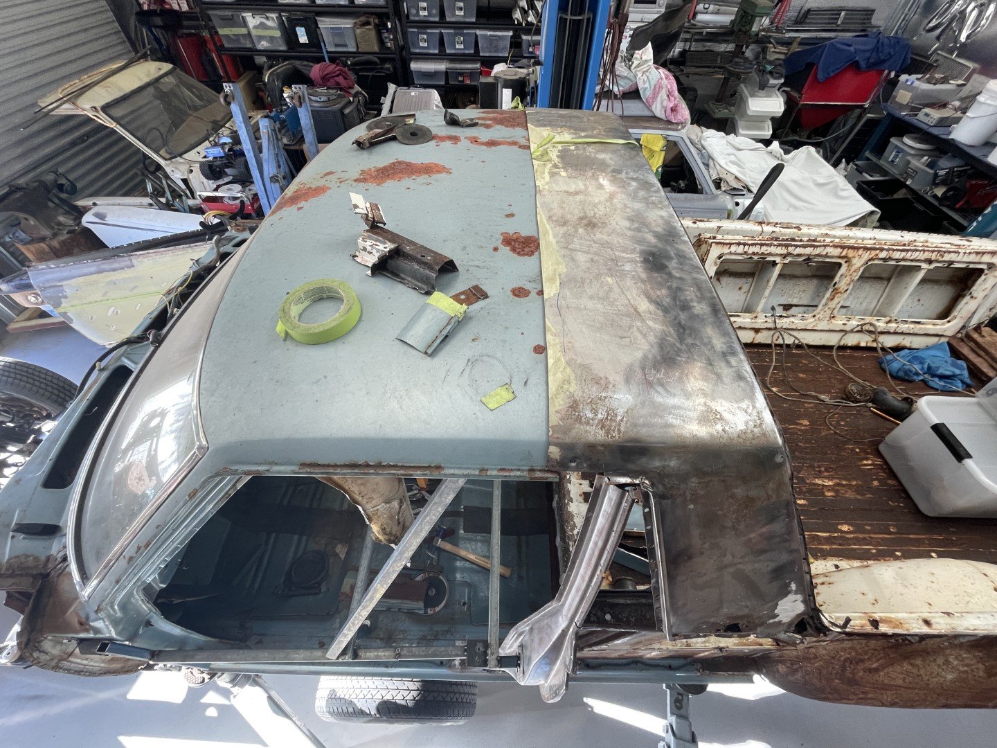
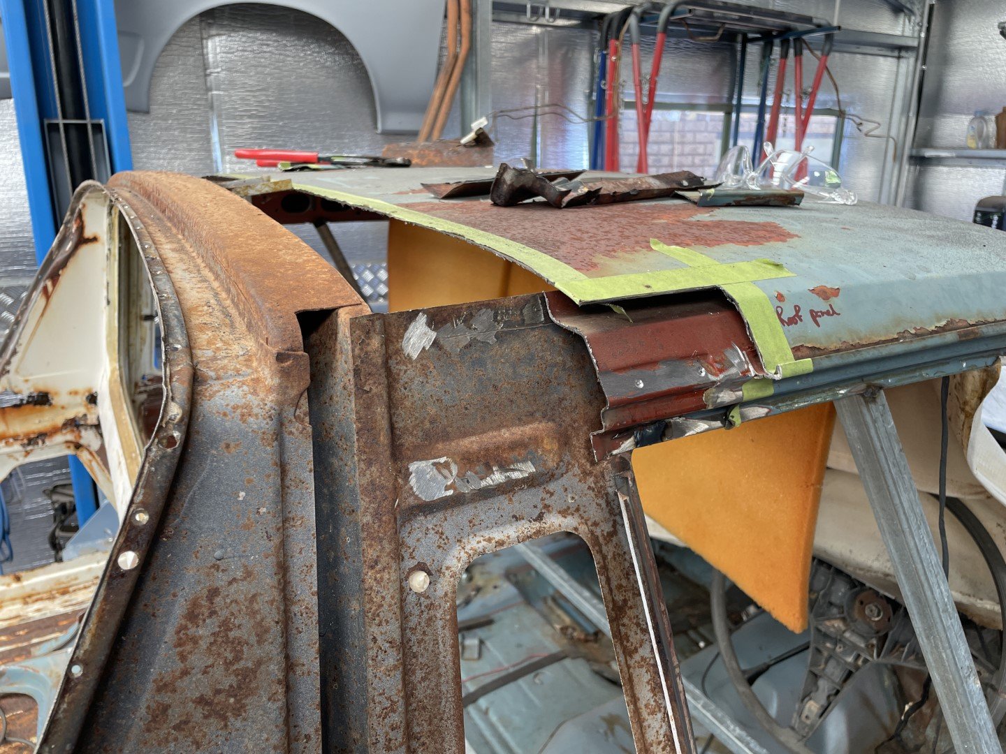
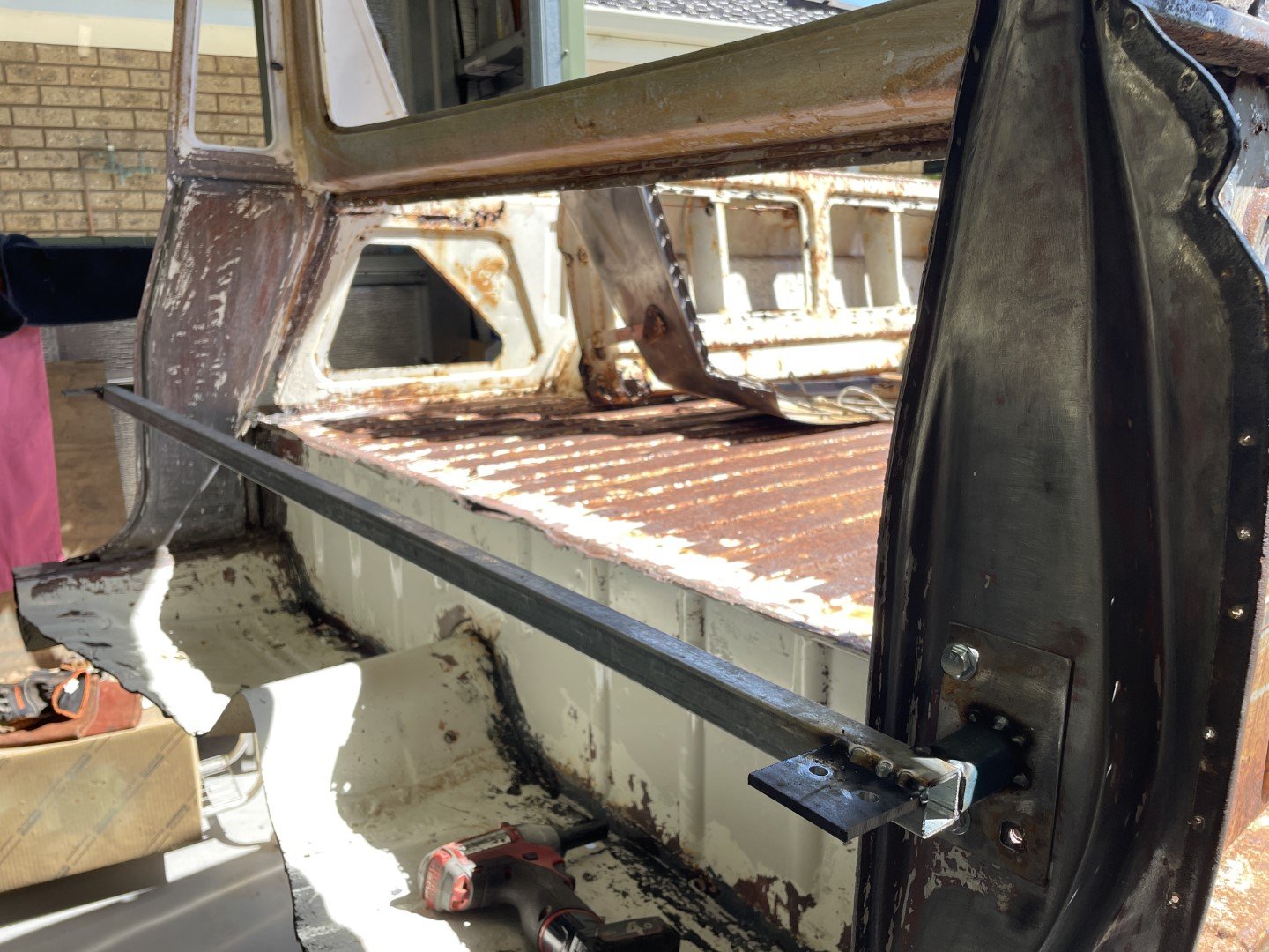
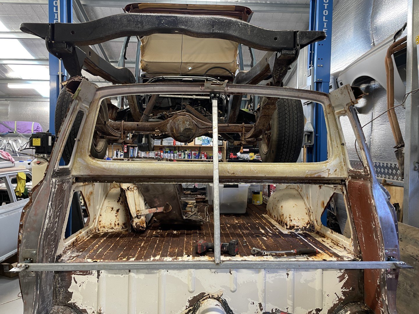
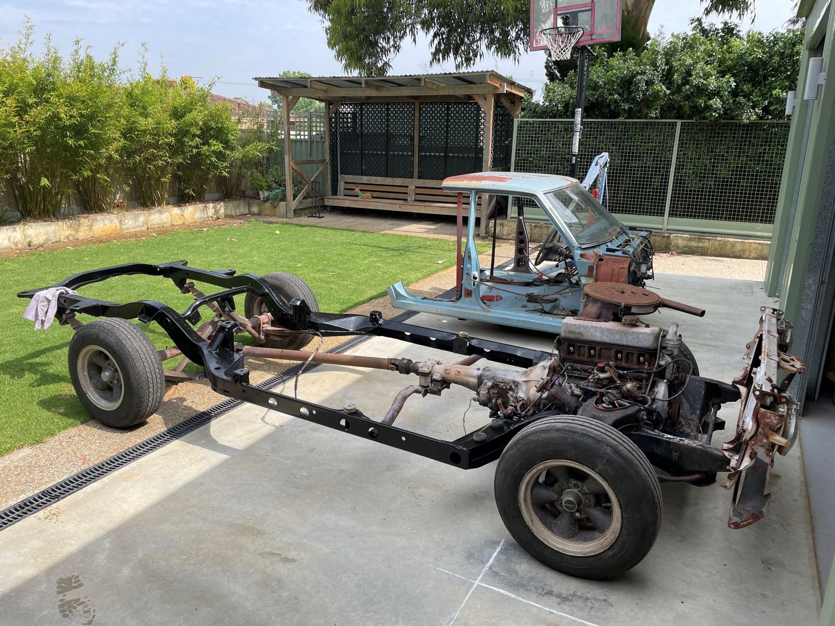
Forgot to add the glory shot of the two bodies sitting in the closest proximity ever. Had to fuck around as my plan of dropping the rear section onto the frame with the front section already in place fell apart due to come inconveniently placed chassis and body cross members. So back onto the trolley went the rear section - the hoist was then employed to lift the front section off the chassis. Chassis wheeled out of the way, heights adjusted and the two pieces were slotted together. I'm pretty fucking happy with that. Door aperture size is correct (measured against the closely available MS55 body parked right next door) Rear firewall alights with the floor pan well (which was cut however many months ago) Grabbed the rear roof panel from the ute and sat it on top to make sure everything was heading in the right direction. Stoked. Still plenty of working out, measuring, cutting and welding (rust repairs more so) prior to sticking these two parts together - but progress is progress.
1 point
-
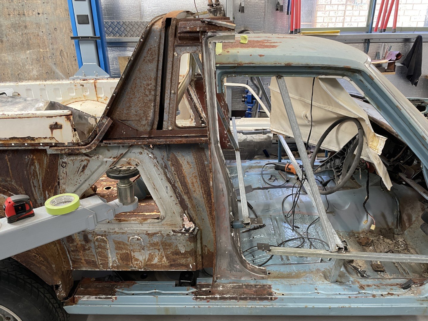
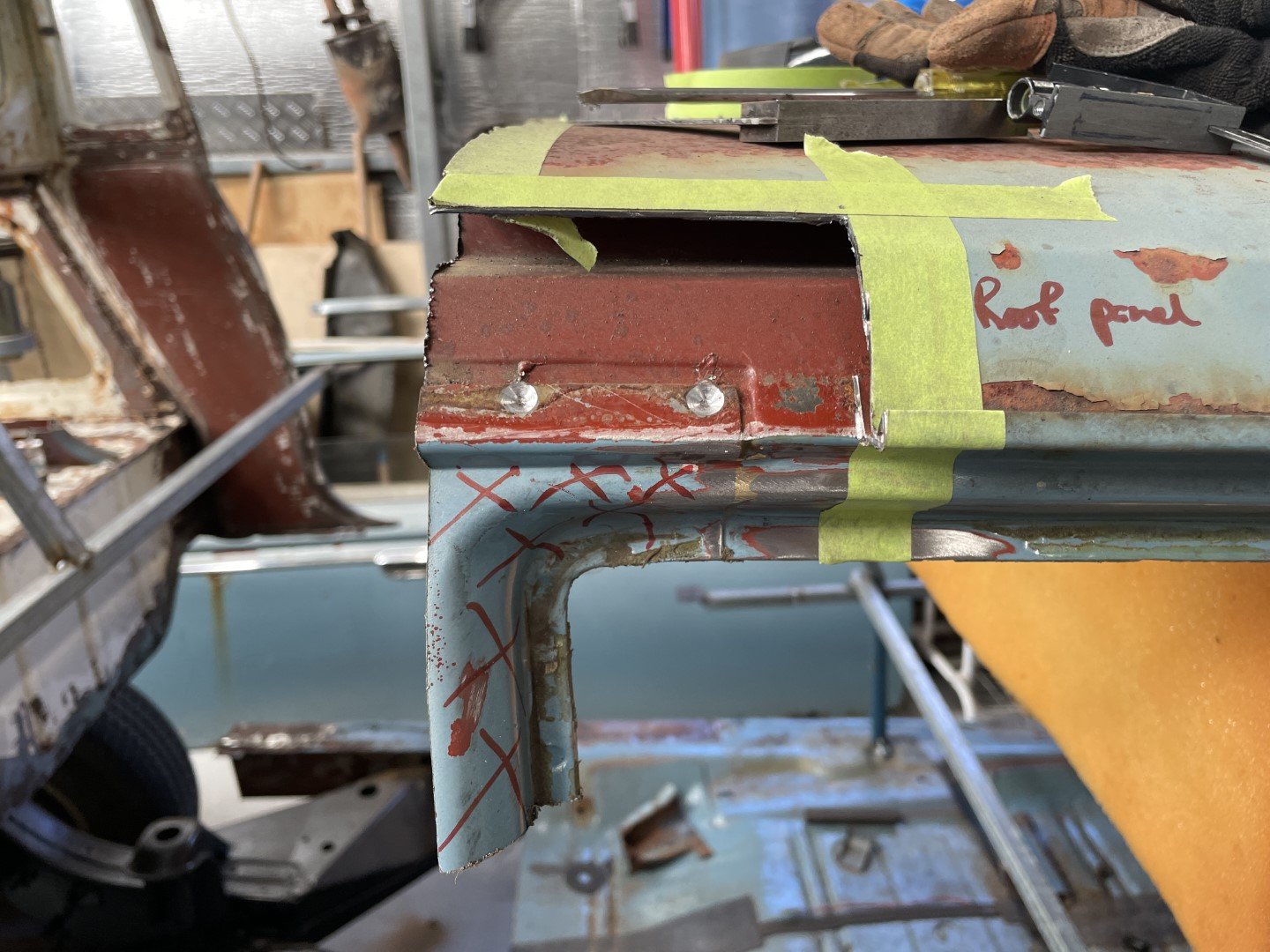
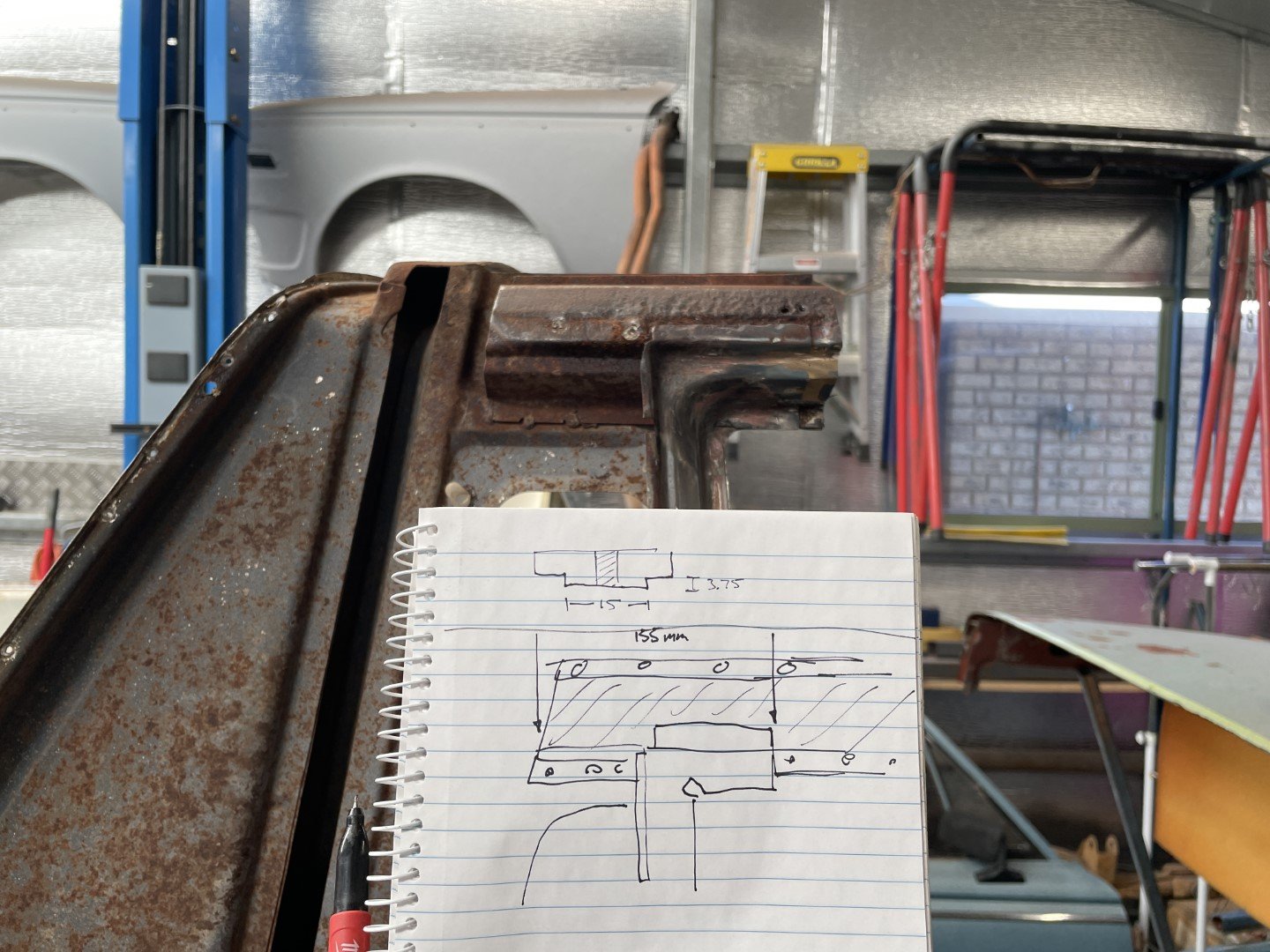
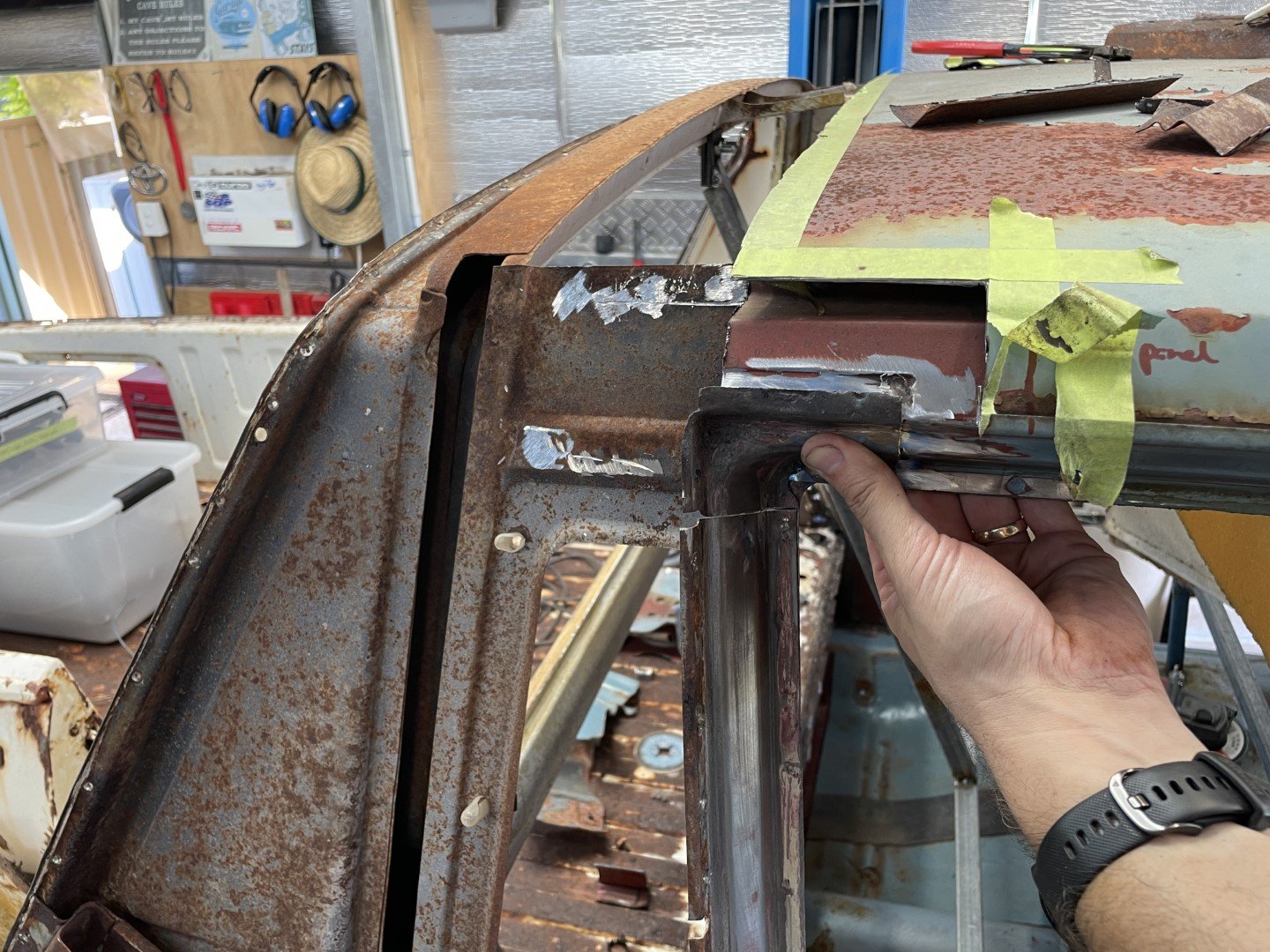
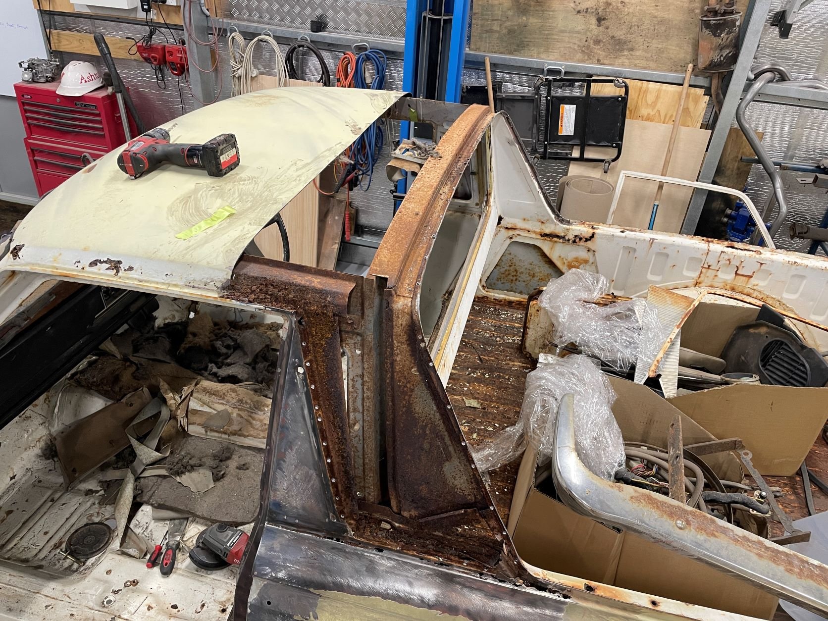
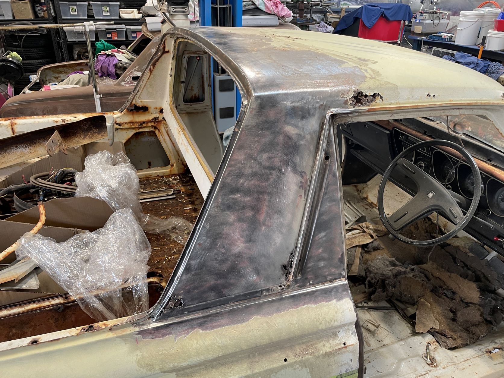
Spent quite a while staring at the intersecting parts to try and work out the best way of joining these things together. My main goal is to stick them together in such a way that all connection points are identical to how it would have come from the factory all those years ago. Not sure how many hours (or beers per hour) were spent staring at it - but it was quite a few. Obviously the B pillar will sit where it needs to sit - but the roof junction was the part that perplexed me the most. Stripped part of the roof panel off to get access to the inner structure. One thing that is clear to see is that this sedan has considerably better rust proofing / priming of panels prior to assembly. Made some detailed drawings of the B pillar structure / junction key dimensions on the ute for future reference; More hours of thinking and grinding saw the inner structure removed from the ute body. Had to cut the corner of the door aperture off to make life a little easier for myself. Resulted in achieving this; From the photo above the intersecting parts become a little clearer. The two pieces of the inner roof structure overlap. Just need to extend the outer part of the inner structure to match the engineering drawings I generated earlier in the day. Nice to find that the door aperture corner that I had to cut out earlier still fits (some fettling required, but close enough for me)
1 point
-
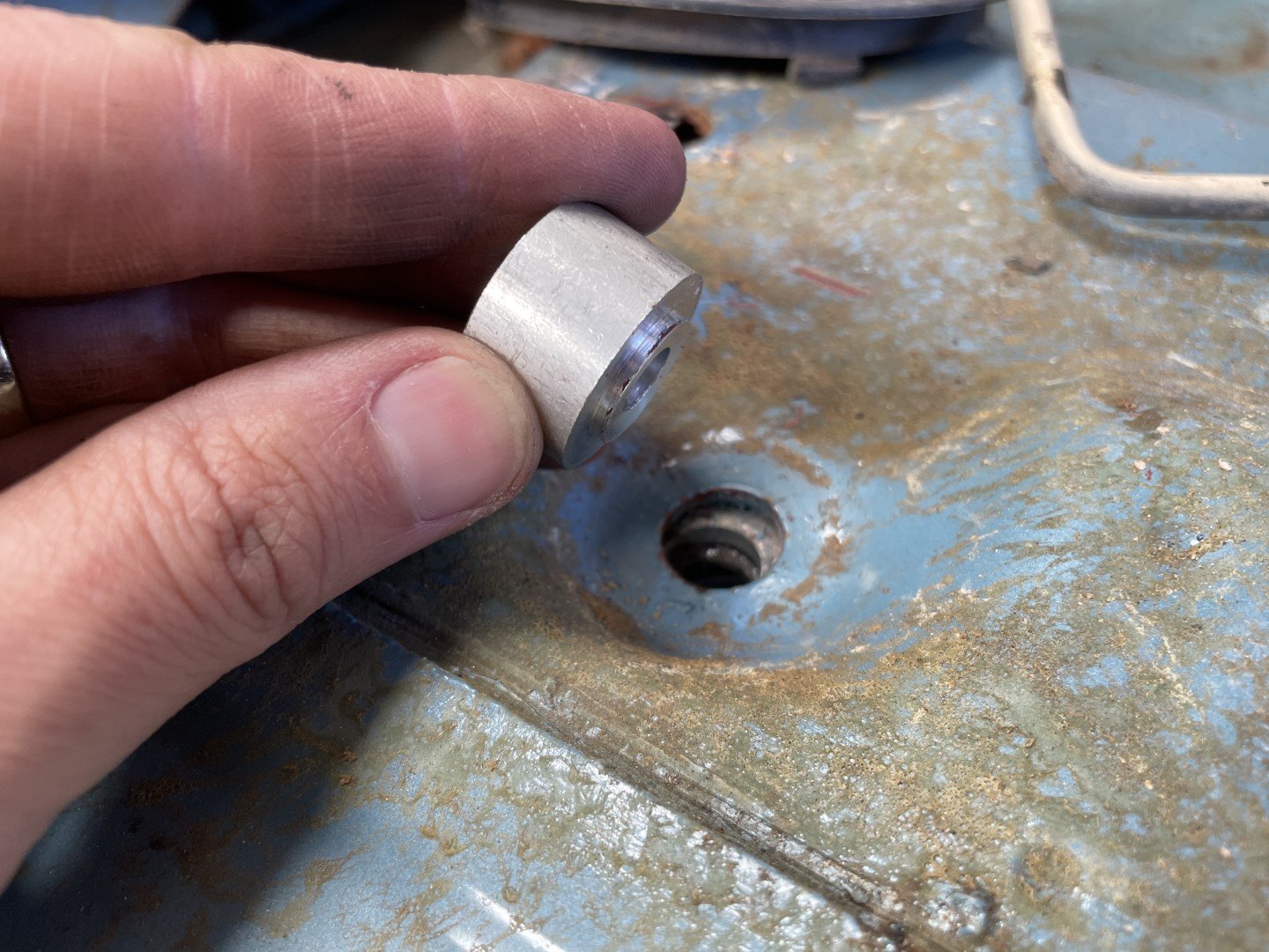
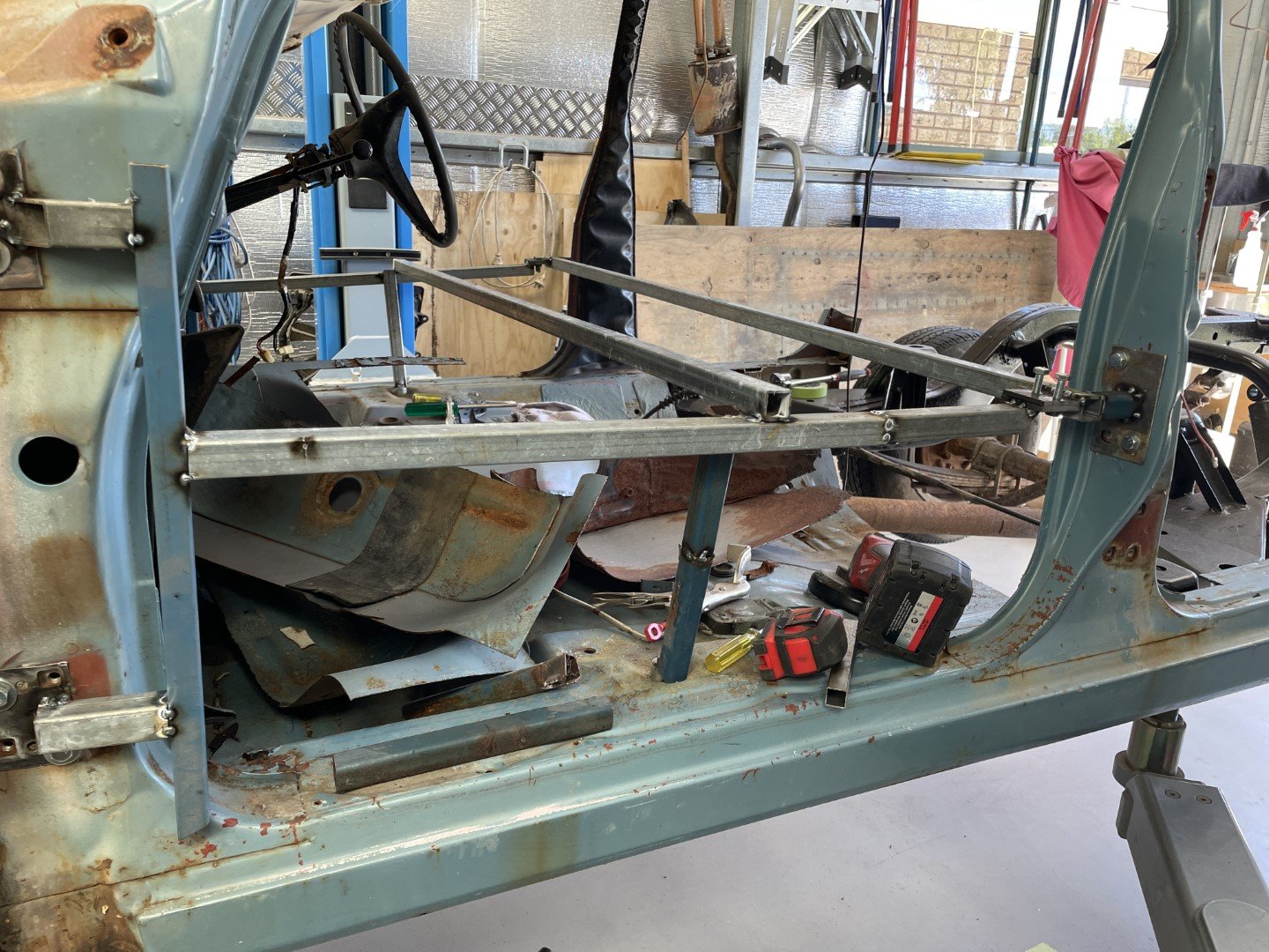
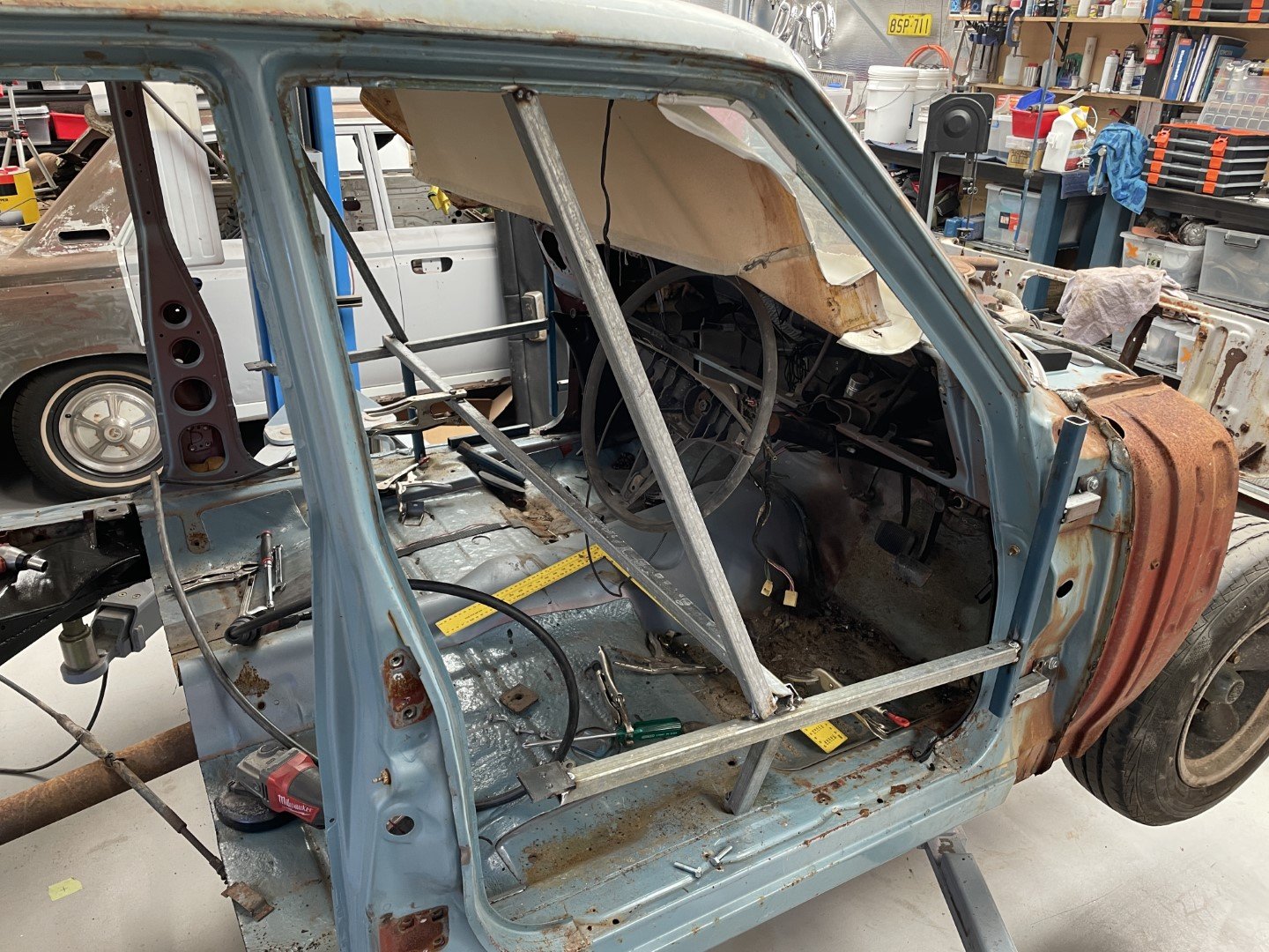
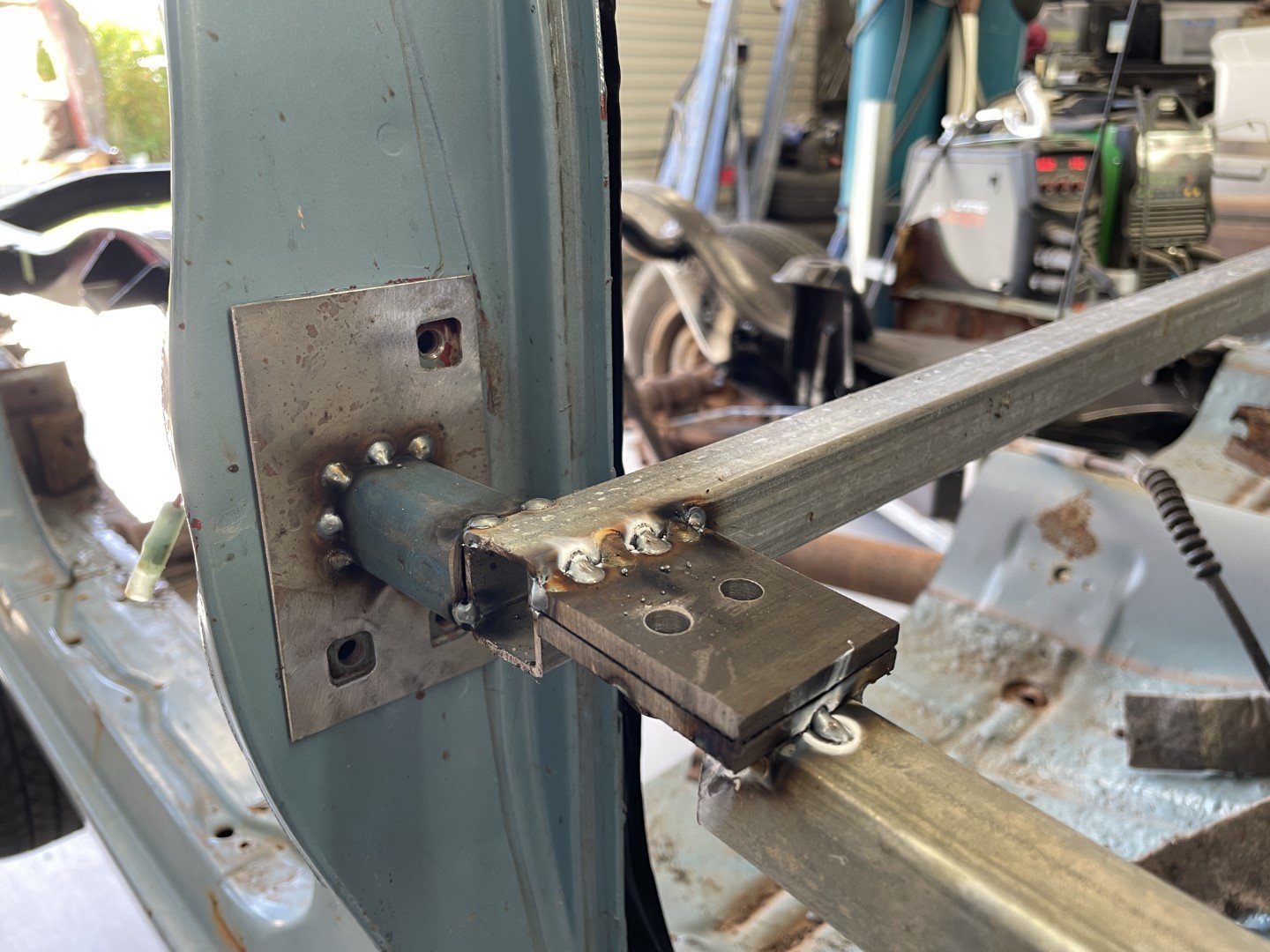
So somehow it's now the tail end of March - how the hell did that happen? Progress has been slow - but progress made none the less. Figured the best thing to do next was fashion some kind of jig that would allow me to throw these two cars together into, well... one car. A frame was considered and then built that would locate (what I feel) are key dimensions - the distance from the A pillar to the B pillar. So I spun up a couple of threaded plugs that would locate to the floor pan; Then proceeded to weld in bars to plates that I could locate on the door hinge and door striker bolt locations; I made the pieces that locate on the B pillars removable so that I could cut the pillars out. Added an extra brace from the middle bars to the roof and then one between both sides. Bolts out - nothing moved which told me it was sorta okay-ish. Then took the B pillar bar and checked it against the ute B pillar. Holes lined up which was nice. Added an extra brace from there up to the rear window aperture to make me feel more comfortable about its position in space;
1 point
-
Like nails down a chalkboard. This is the first drive running on 5 cylinders. Apologies for terrible camera work.1 point
-
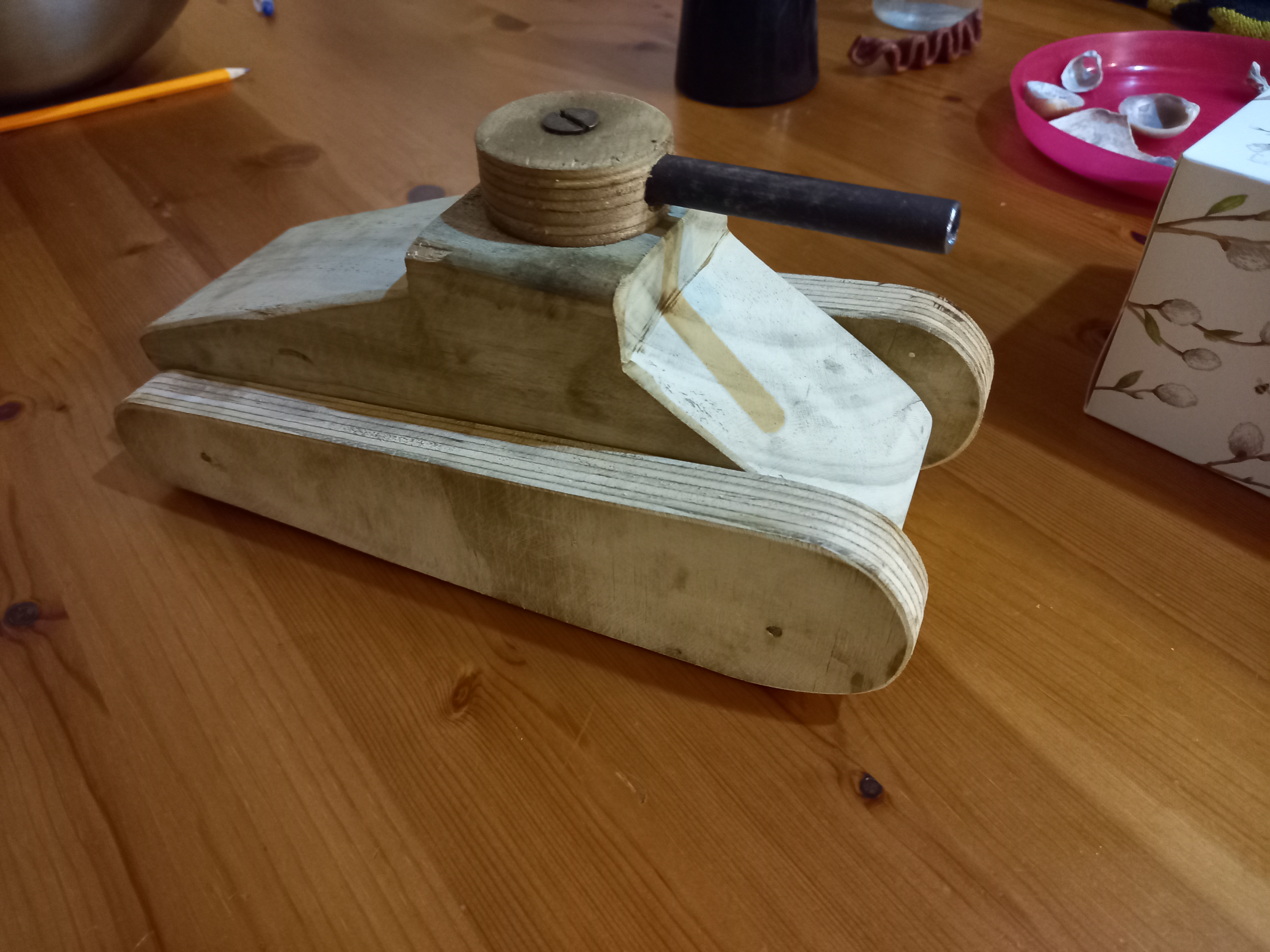
A nieve Sherman tank that my son requested.
1 point
-
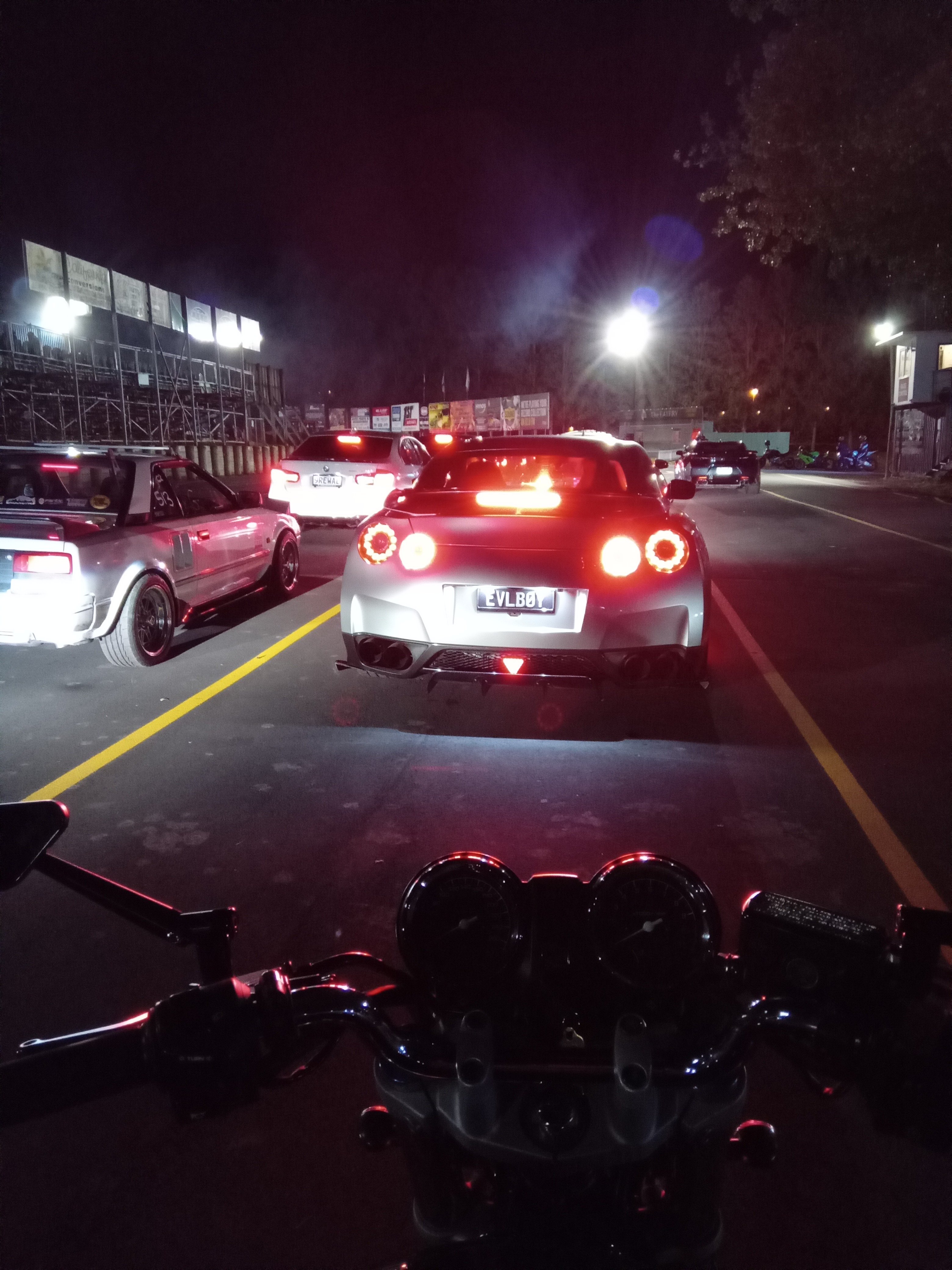
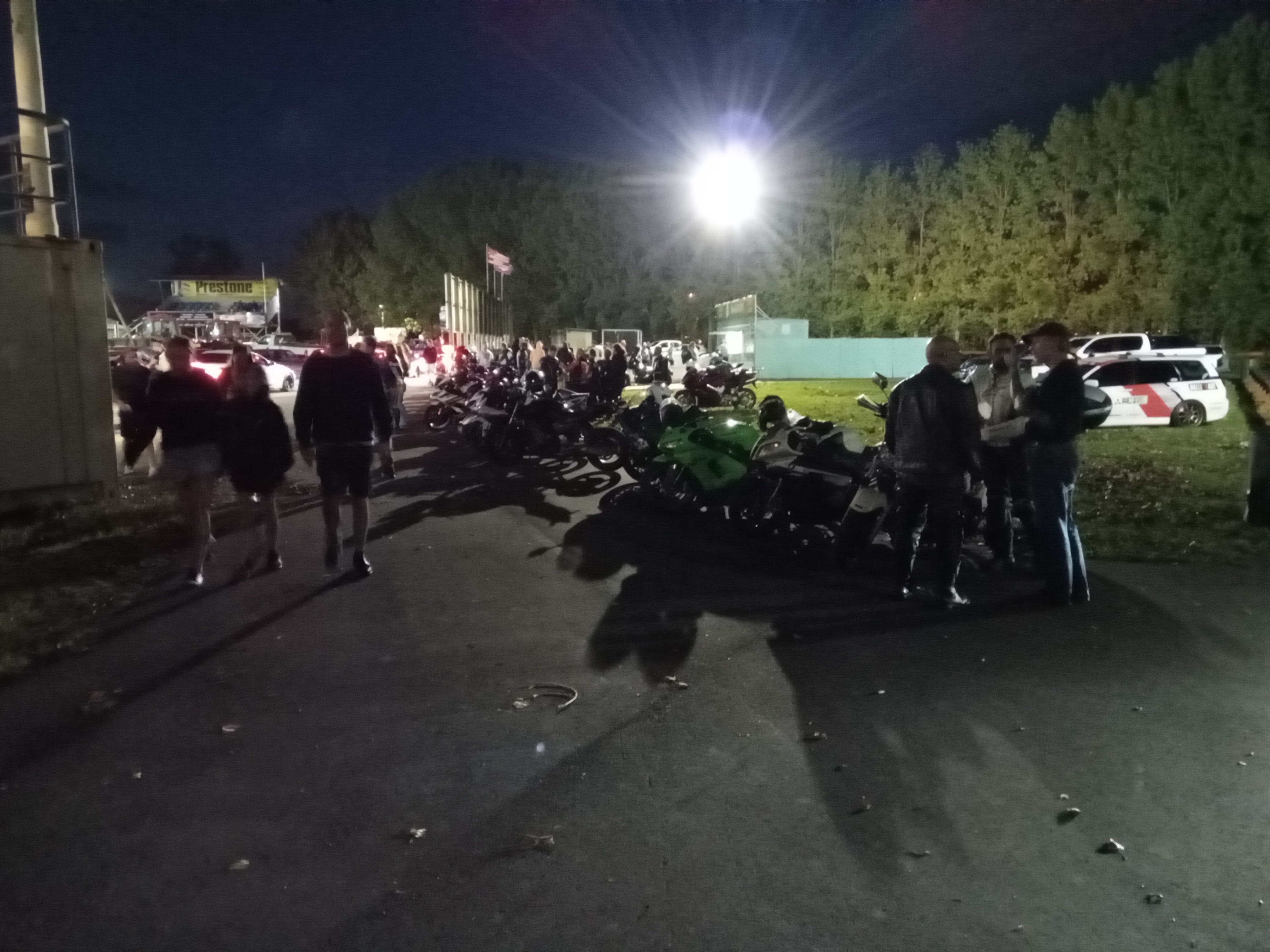
I havent been to the night drags for aaaages , last minute i decided to go. Cbf with friday traffic in the plymouth,and ive wanted to see what the bike is capable of since i got it Best i did was 12.3@110 I was yarning to a guy who has the same bike but his has done a heap of hard kms He was interested to see what mine was like compared to his, so he did a pass on my bike, 11.8@116 The difference was,hes not a fatty, ha
1 point
-
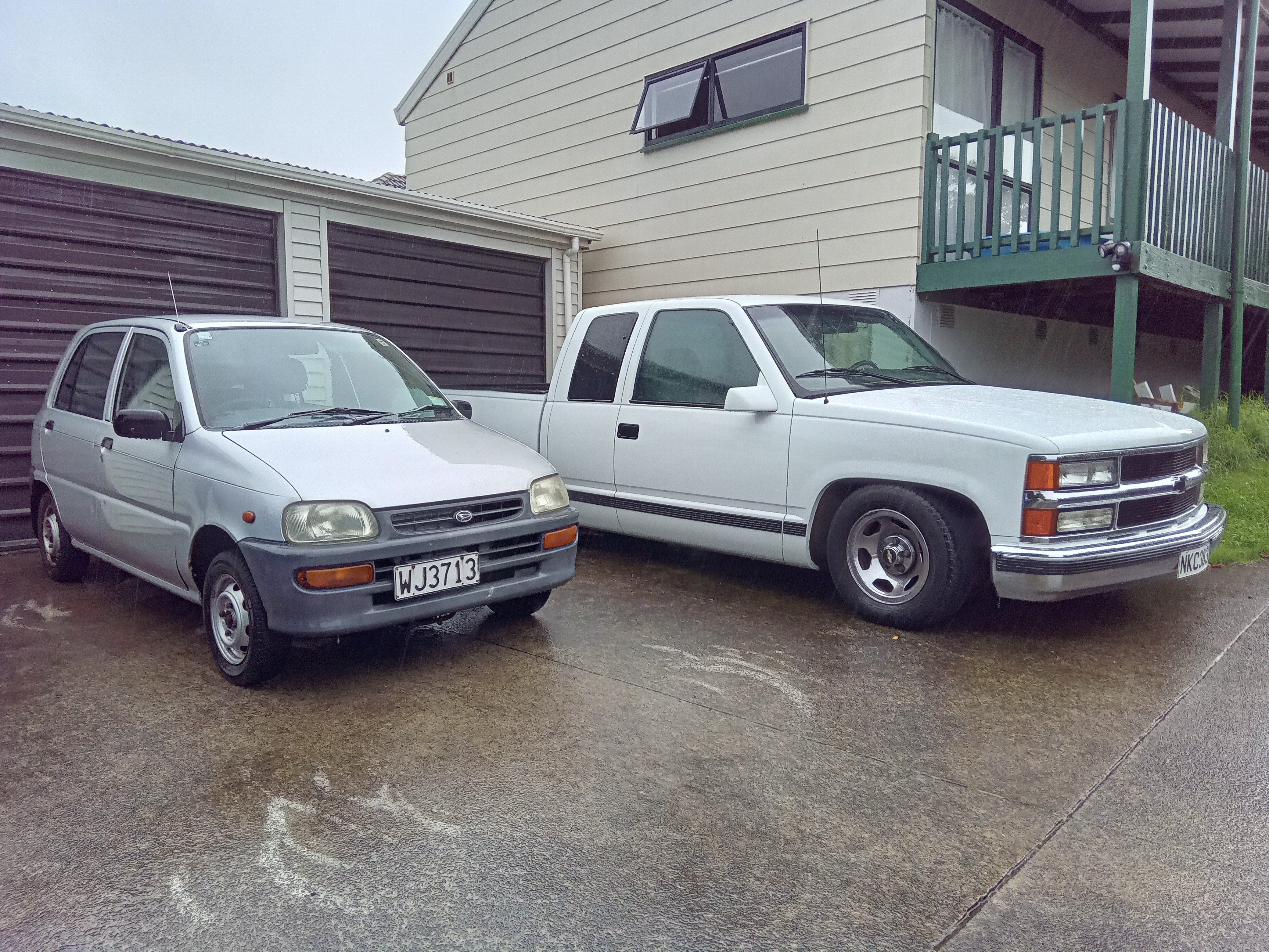
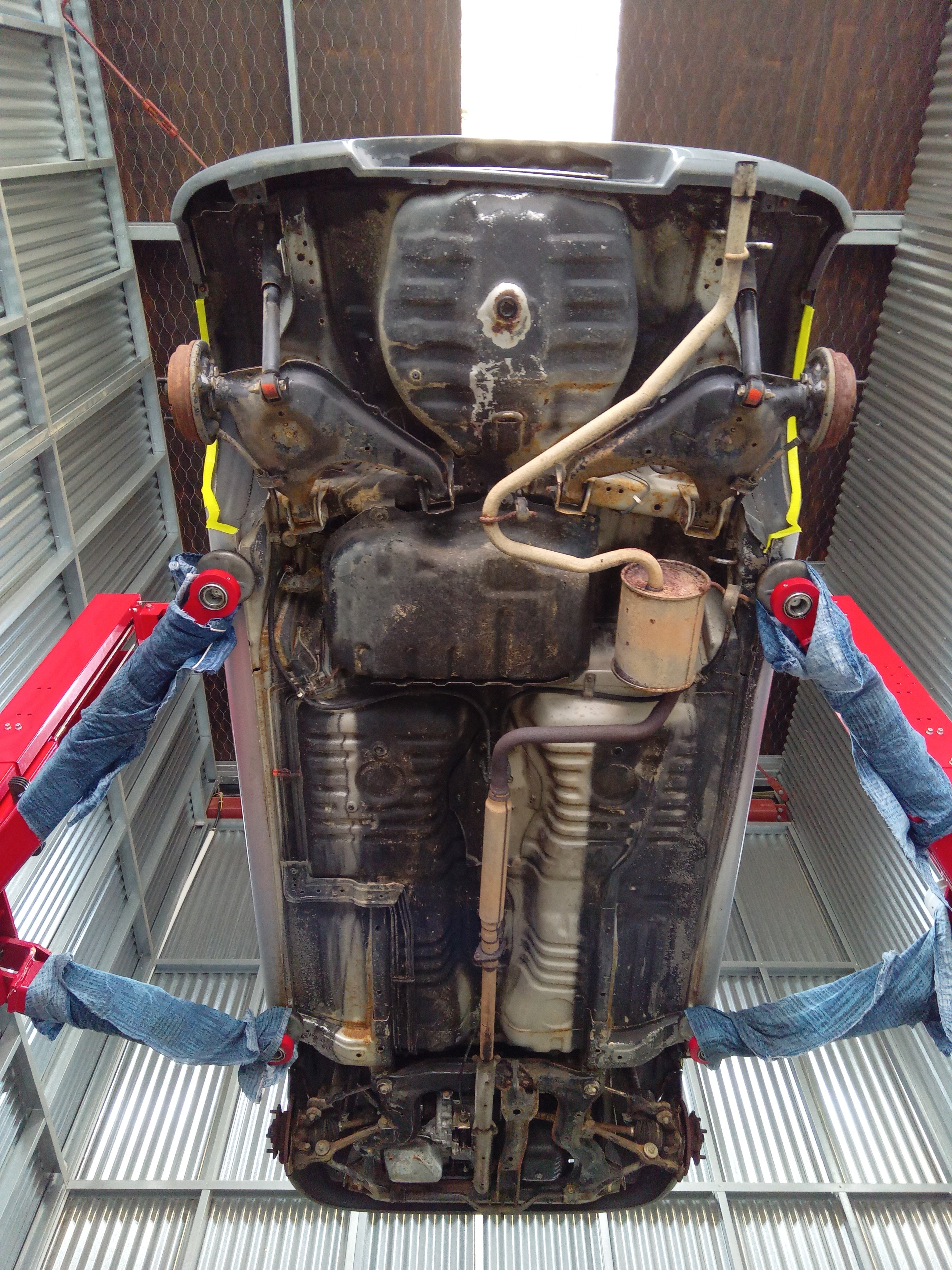
Fully restored underbody with some rejuvenation spray Got some small car barrying this morning,stopped to get a coffee and parked next to a k11 which looked ginormous next to this thing I walked out and a dude sitting outside started sharning about; how his k11 looked big it had a 1000cc motor , and i had 12 inch tyres so that must be cheap,his has 13s is it a 800cc? Whoa 660cc that must be good on fuel, oh its an auto? My brother has a manual one cool
1 point
-
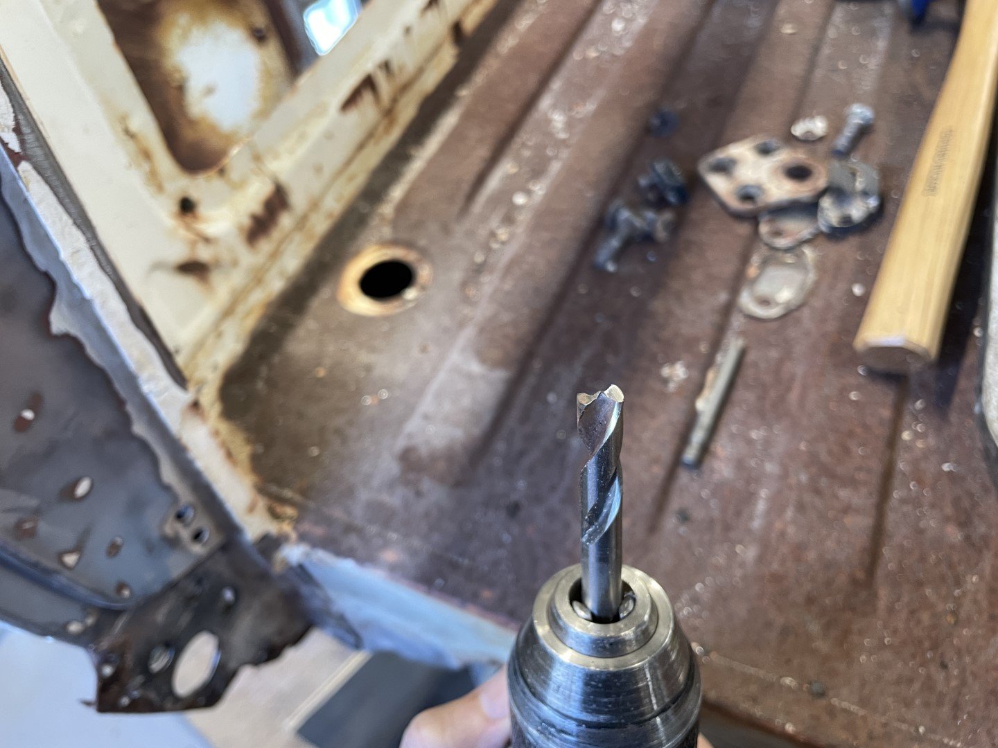
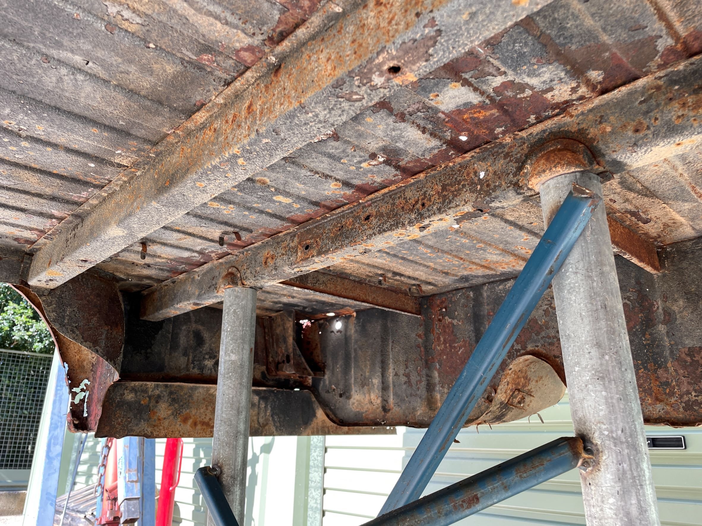
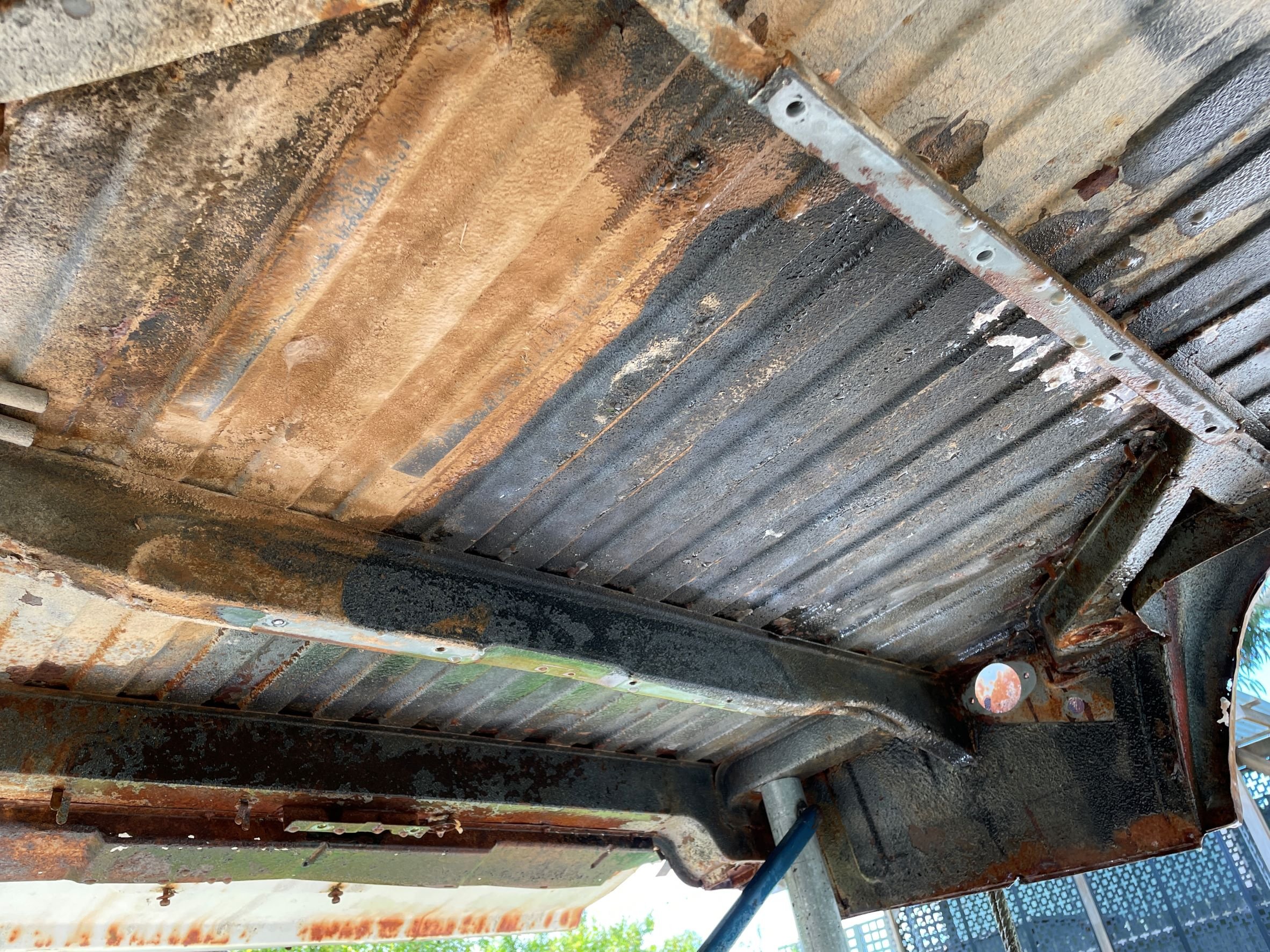
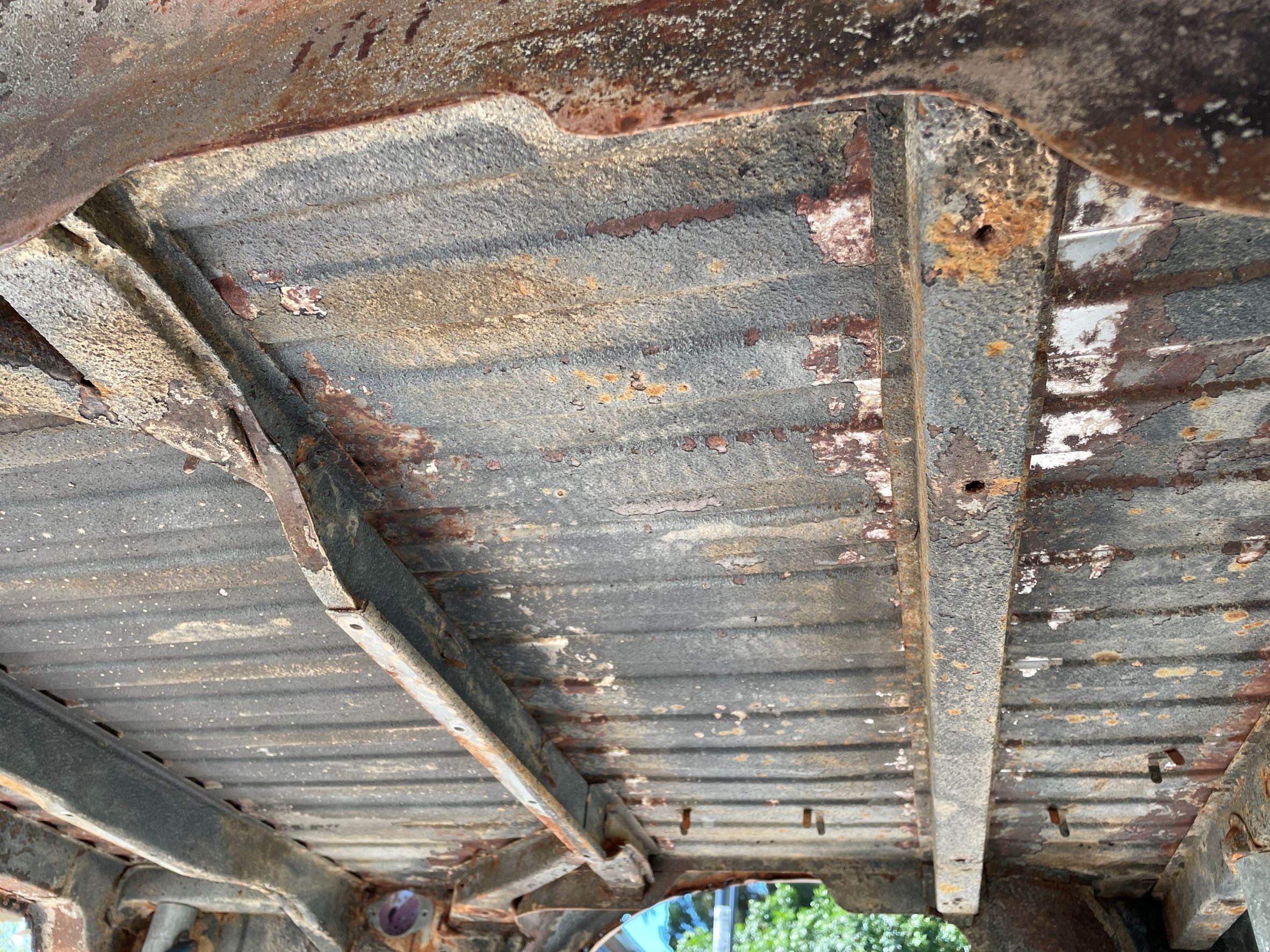
Treated myself to a proper spot weld drill bit - really wish I'd done that sooner. Probably could have ground a normal drill bit to work in a similar fashion - but I'll worry about that once I ruin this one. I set about getting access behind some other panels. It was hot. Like, fucking hot. Because I've filled my shed with so many cars and parts, I'm working up against the roller door that is on the Western side of the building. With the sun having shone DIRECTLY at said roller door since 1pm, it was now a giant radiator. Yay. Anyhoo - after nearly an hour of drilling I was covered in swarf and sweat, but had achieved a thing. I'm super glad that someone had made it look somewhat pretty on the outside - because it's fucking ugly underneath. I'm starting to think that it might be a good idea to see what it'll cost to blast all these inner panels....
1 point
-
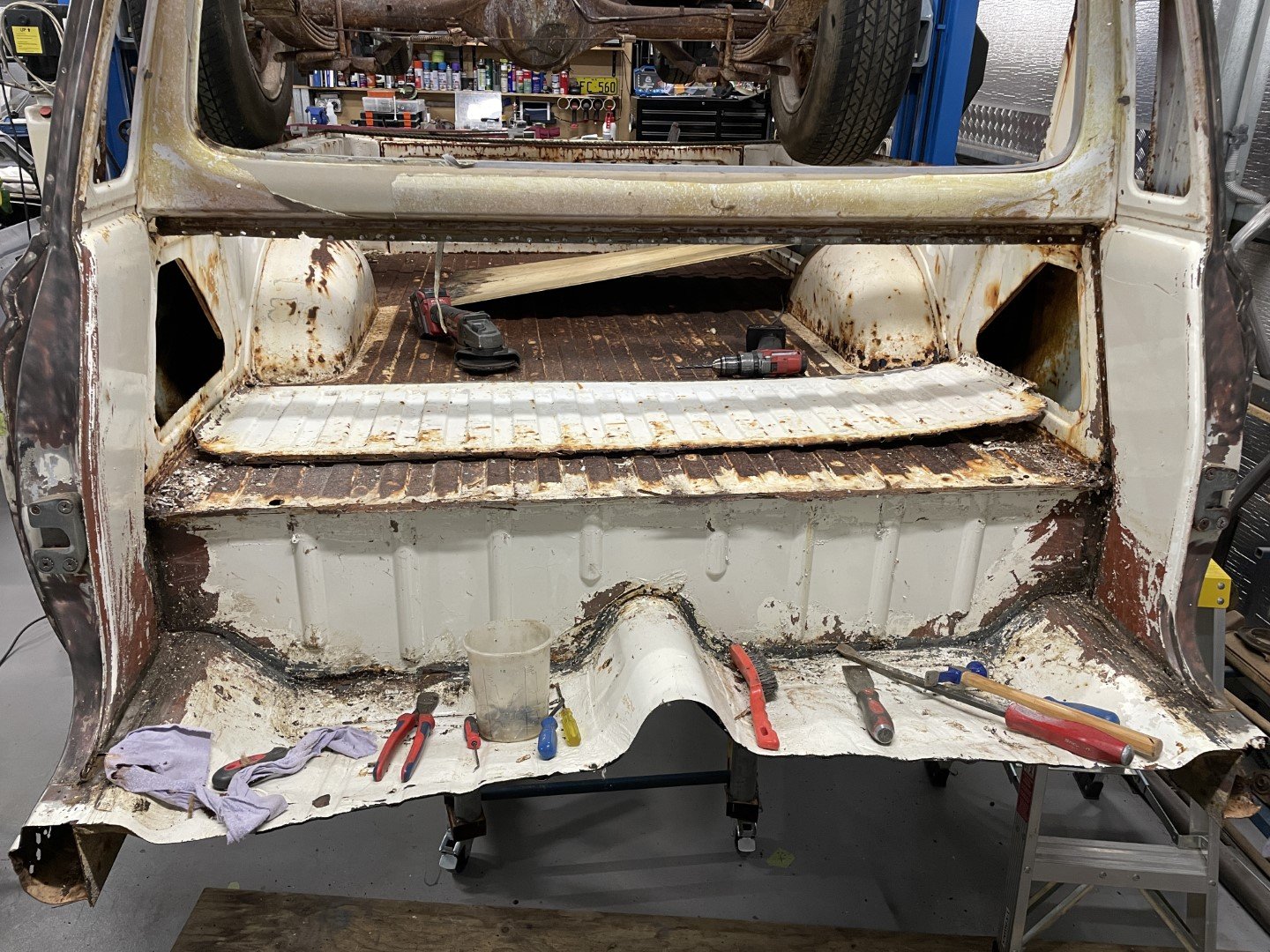
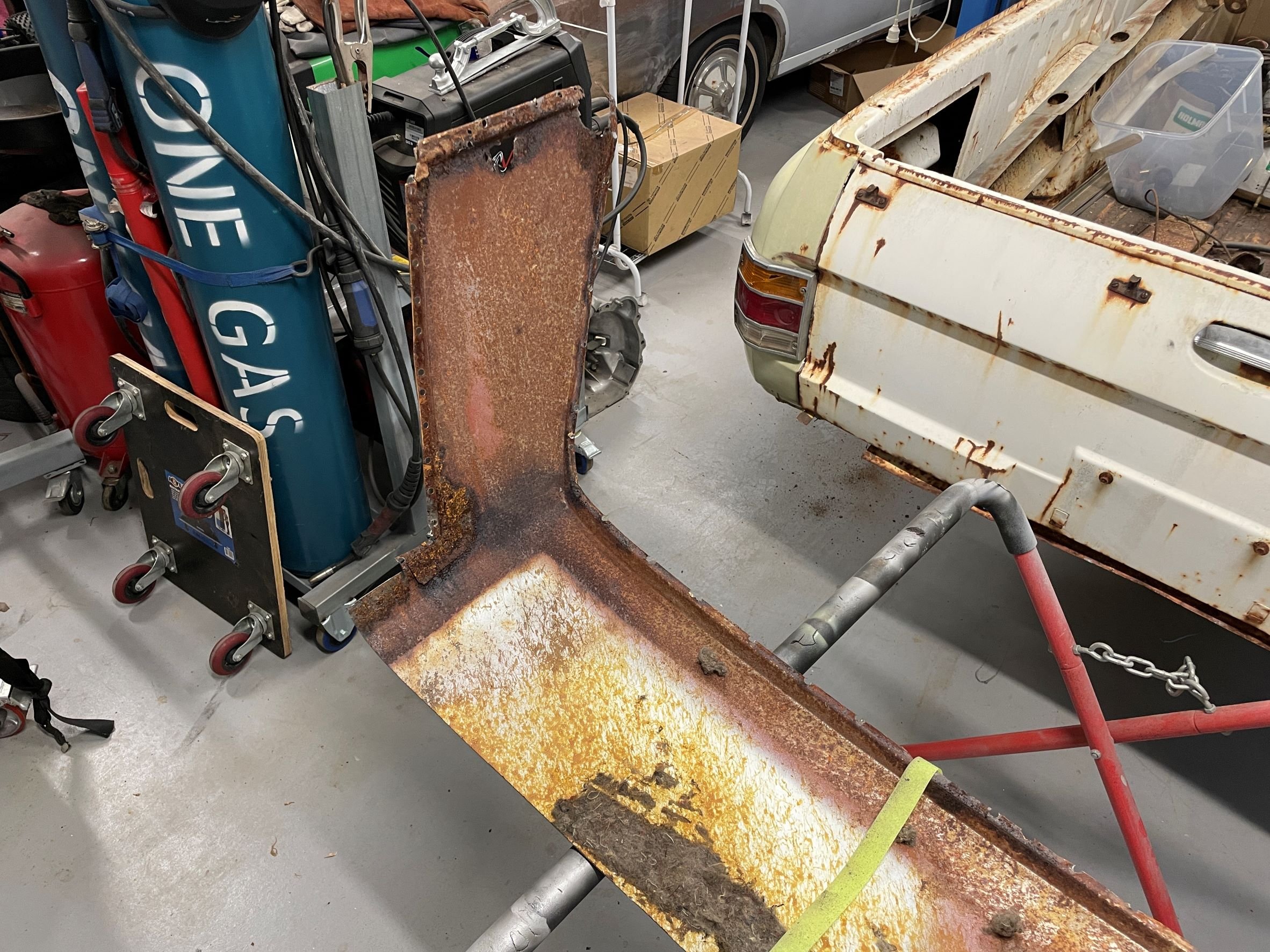
So with my 'I'm a twat' hat firmly in place, I proceeded to remove the panel. The driver's side was pretty easy as most of it had rusted away. The passenger side was more difficult, as not so much of it had rusted away. Panel was tucked up here under another panel. The process in which they assembled this thing is a little more clear now. VICTORY. Whilst my plan to build the trolley at a reasonable 'get underneath and pressure clean the bastard' height seemed like a good idea - it wasn't great for the whole 'now you need to get in / around the tray to drill spotwelds' working height. Got the fucker out anyway after much sweating and cursing. Access granted to both sides now. Spent two minutes admiring my handywork before cracking a beer and watching the last 10 overs of the 20/20 cricket.
1 point
-
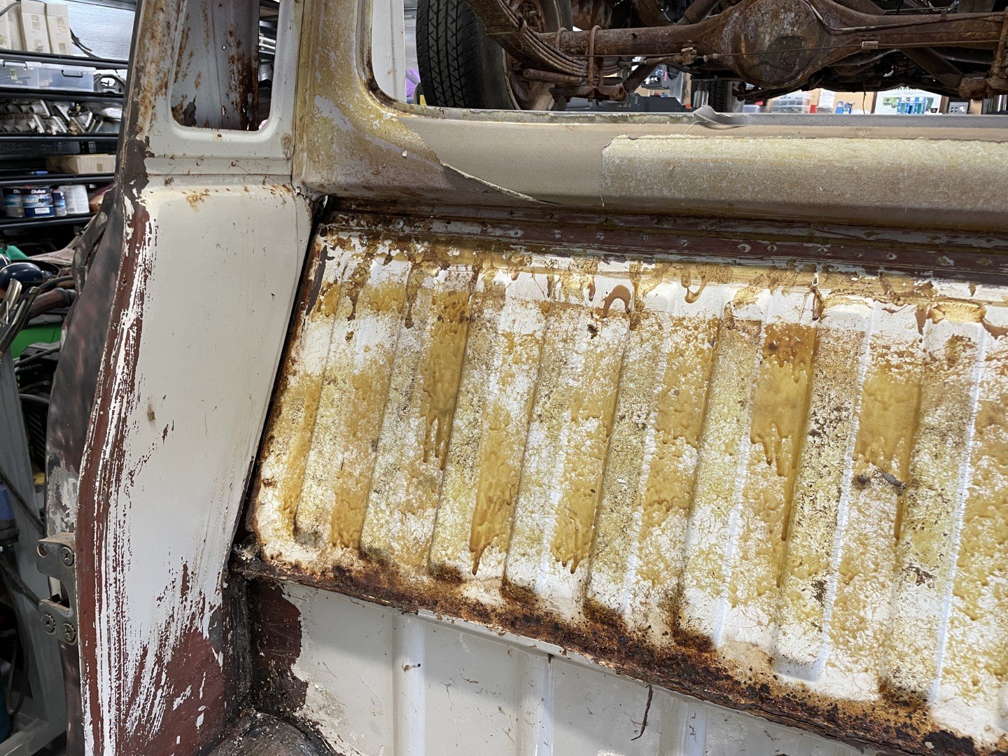
Rightly or wrongly, I figured the best way to get access to the worst parts was to remove the firewall pane that sits above the tray line / under the rear glass aperture. So I started drilling out the billion spot welds along the lower, upper and side seams. I took this approach because I thought I had a decent understanding of how they put the body together at the factory. Boy was I fucking wrong.
1 point
-
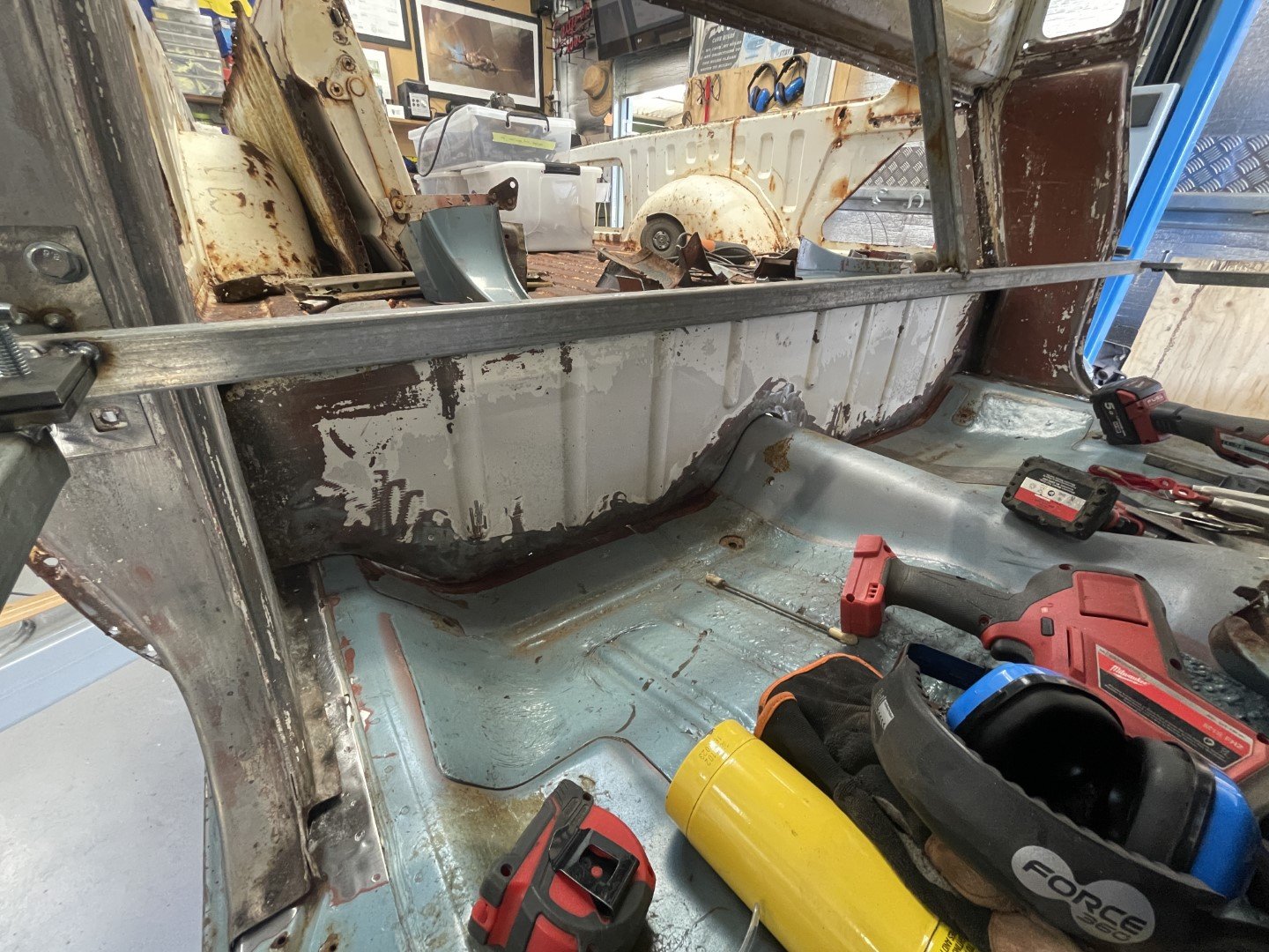
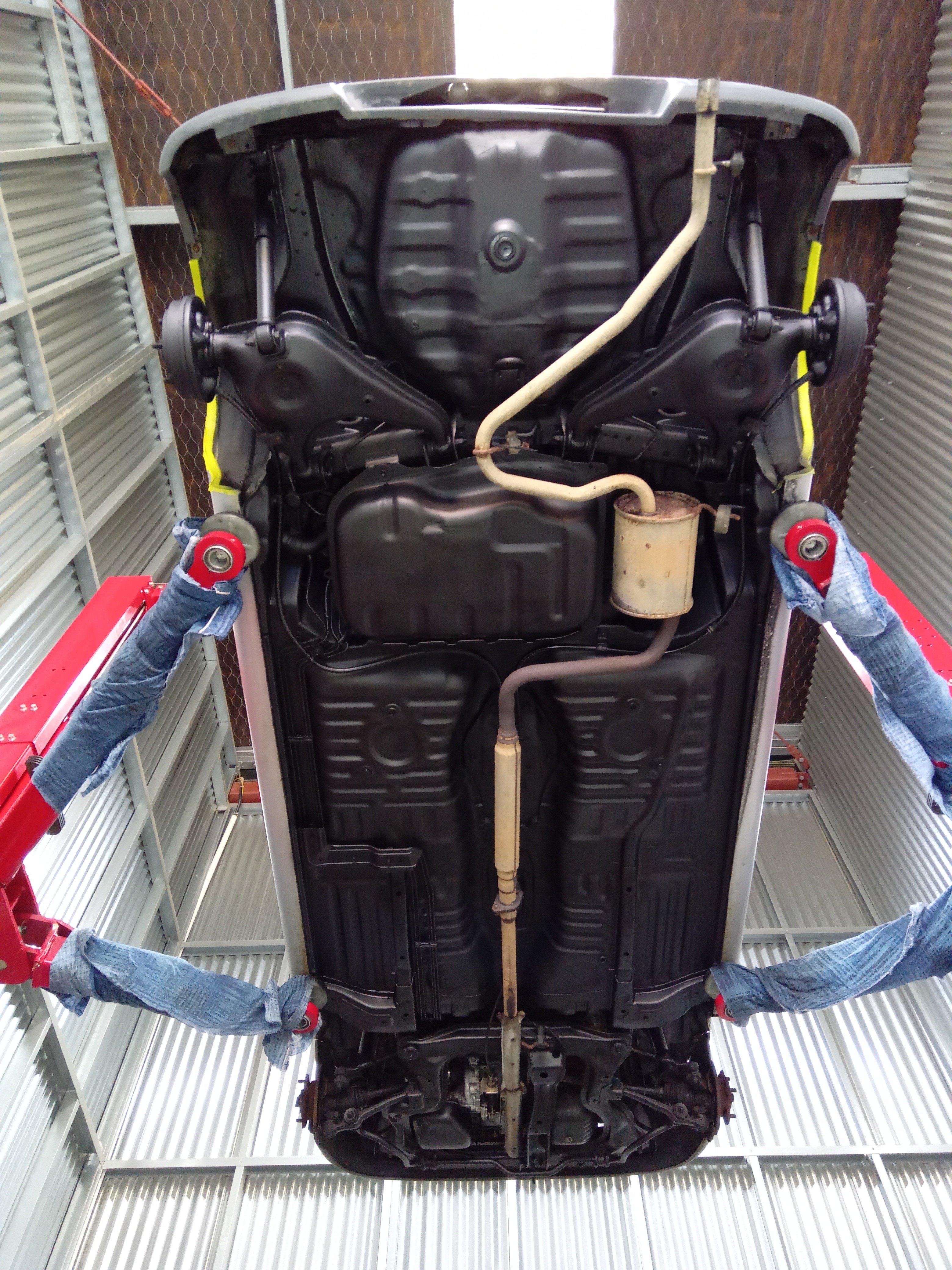
Karcher + turbojet head thingy employed - dust / rust / loose paint blasted away. Area above the fuel tank looks mint-ish. The rest of it is not as nice - still lots of shiny steel revealed once the sound deadener was blasted away. Rustier parts towards the front of the tray.
1 point
-
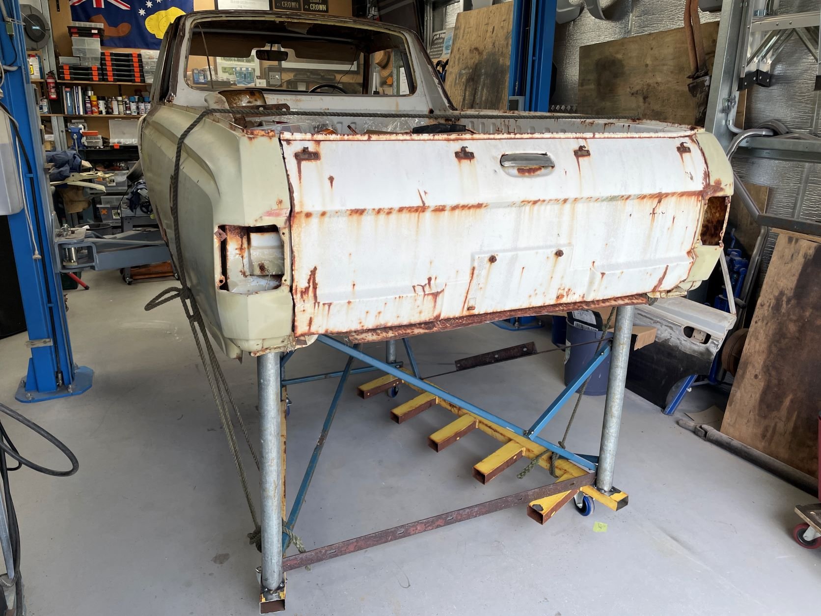
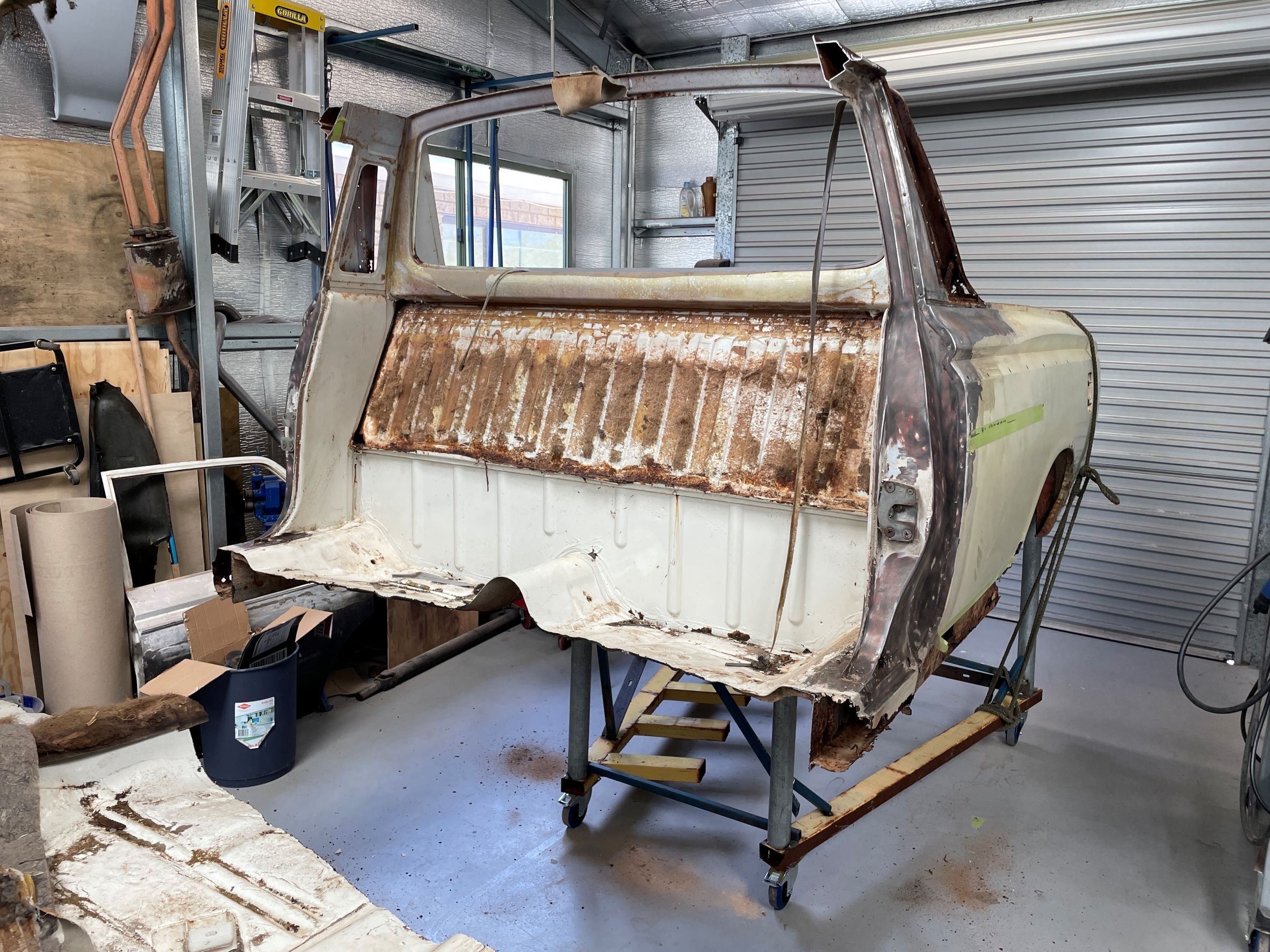
Stripped the underside of its fuel tank and (minimal) wiring, welded up a trolley out of random scrap steel I had lying around and prepared the surgery for the operation. Cut in half. Tray end didn't topple off the trolley. Win. Nice standup driving position. Wheeled outside for some sun and underside cleaning.
1 point
-
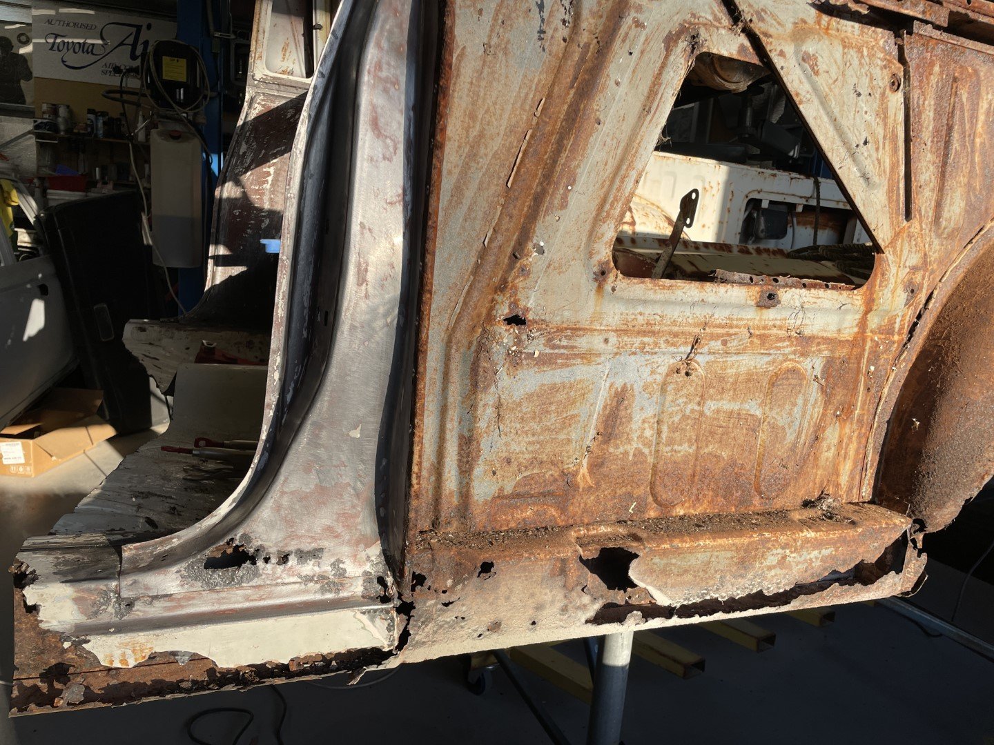
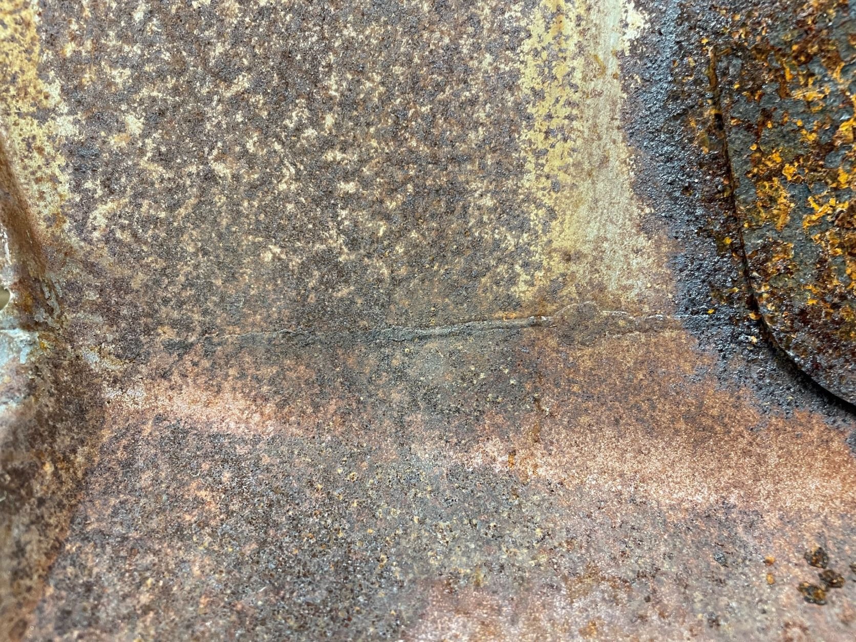
The RH side of the B pillar didn't look so bad - but the LH side looks rooted. Knowing that the injuries to the poor old girl would go deep, I figured the only way to really know what was going on was to dig down through the panels. Line drawn, drill bit sharpened and safety squints engaged. Yuck. Not as yuck, but still yuck. Can't half tell why the inside of these things rust - primer / paint application back in the day can only be described as 'half arsed' Interesting detail in the panel - where I was expecting to see a step in the panel and lead application turned out to be an old butt weld that was seemingly stamped smooth. Looks like they welded 'wings' onto a larger piece of steel before stamping the whole roof panel and B pillar as one assembly for manufacture.
1 point
-
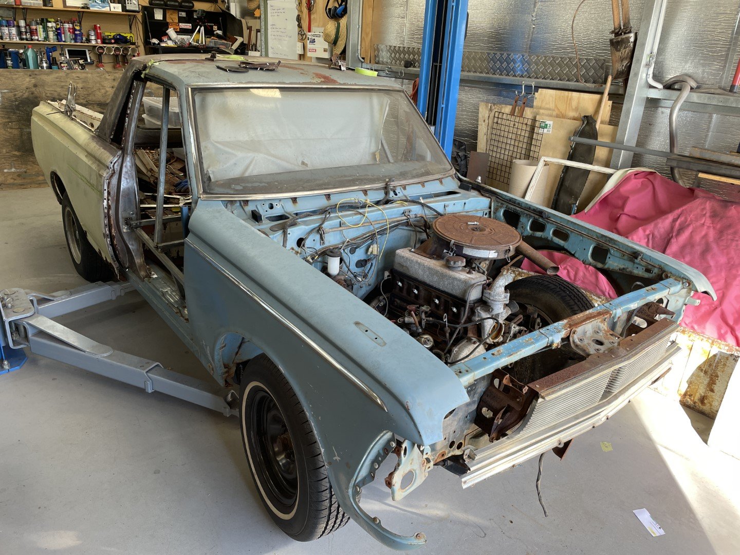
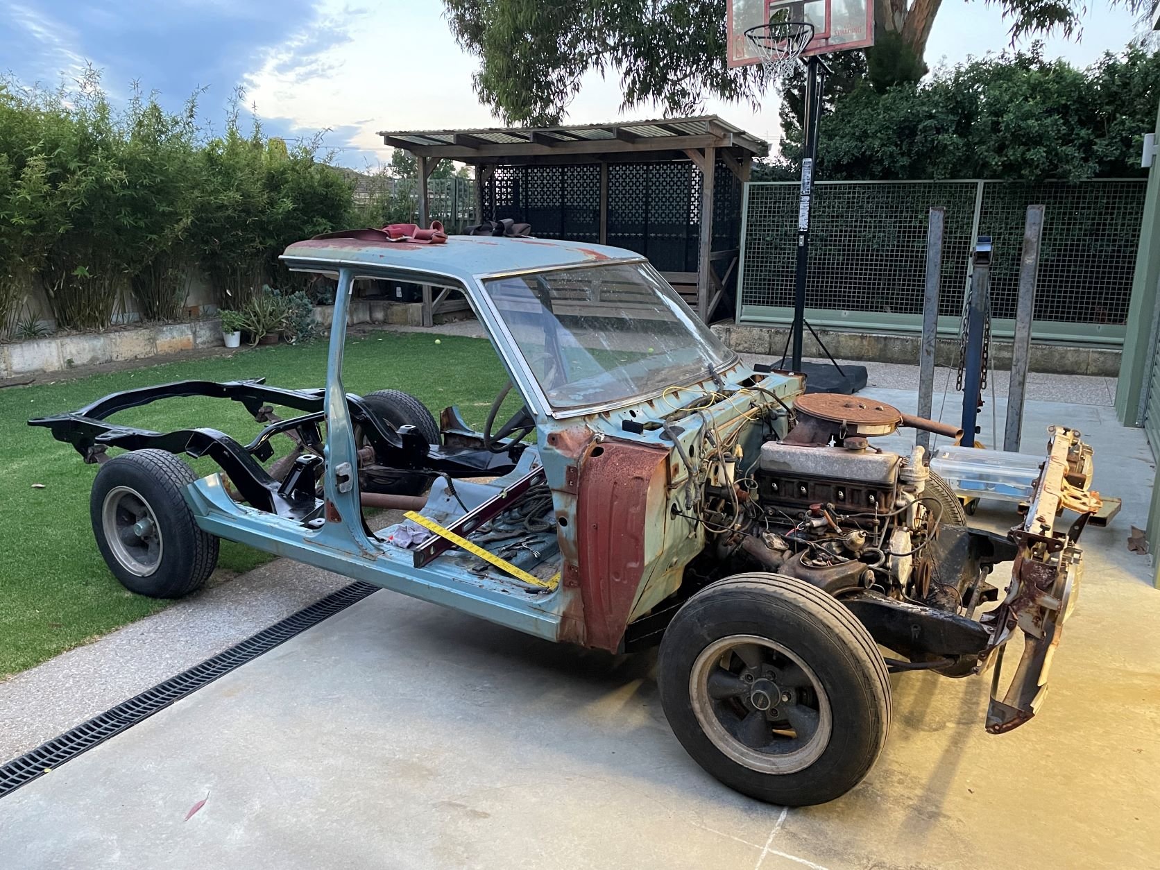
In between the normal Day Job / Kids / Home stuff, I found some time to get at it a little more... aggressively. Body removed. Pushed it outside where I could give it some loving with the 'grinder wire wheel of death' Attacked it with some chassis black to make it look a little more respectable. After much jankyness in relation to slinging / lifting equipment and strategy, I managed to lift the sedan body on after a little bit of trimming to clear one of the rear body mounts. From here, it took a few more beers and hours staring at the ute body to best work out how I was going to approach the merger. First off, I figured the best place to join both parts was.... the middle. Grabbed out the tin of paint stripper and let the paint work have it. Employed the old boy to wire wheel the bubbly paint so I could see what was what - was surprised to find a lack of lead between the roof and 'B' pillar panels. Even the most casual observer can see that this thing is more rust than anything else.
1 point


This leaderboard is set to Auckland/GMT+12:00