
Leaderboard


Popular Content
Showing content with the highest reputation on 05/10/22 in Posts
-
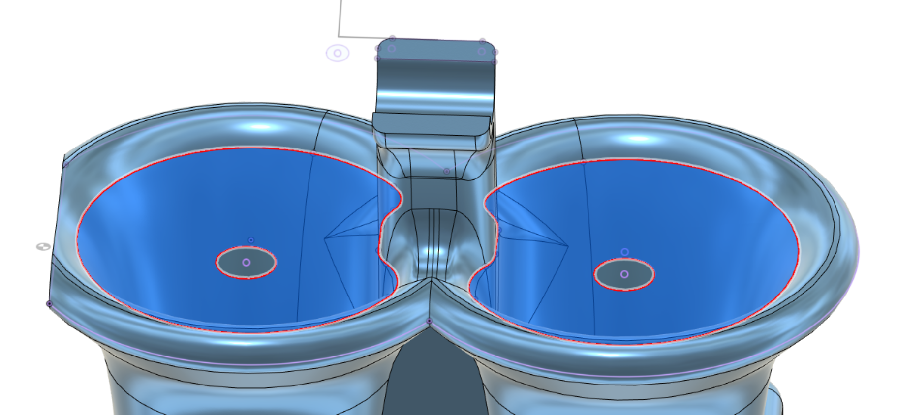
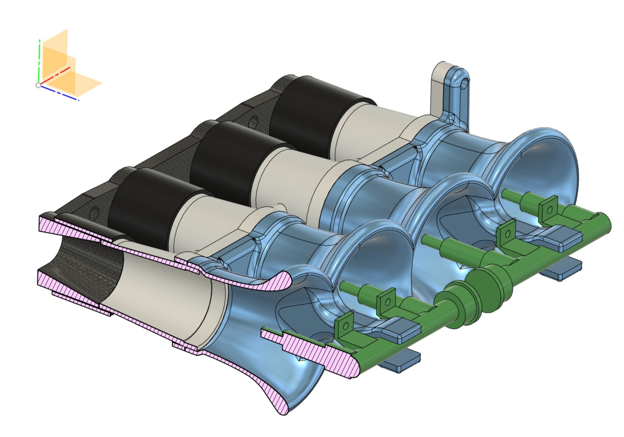
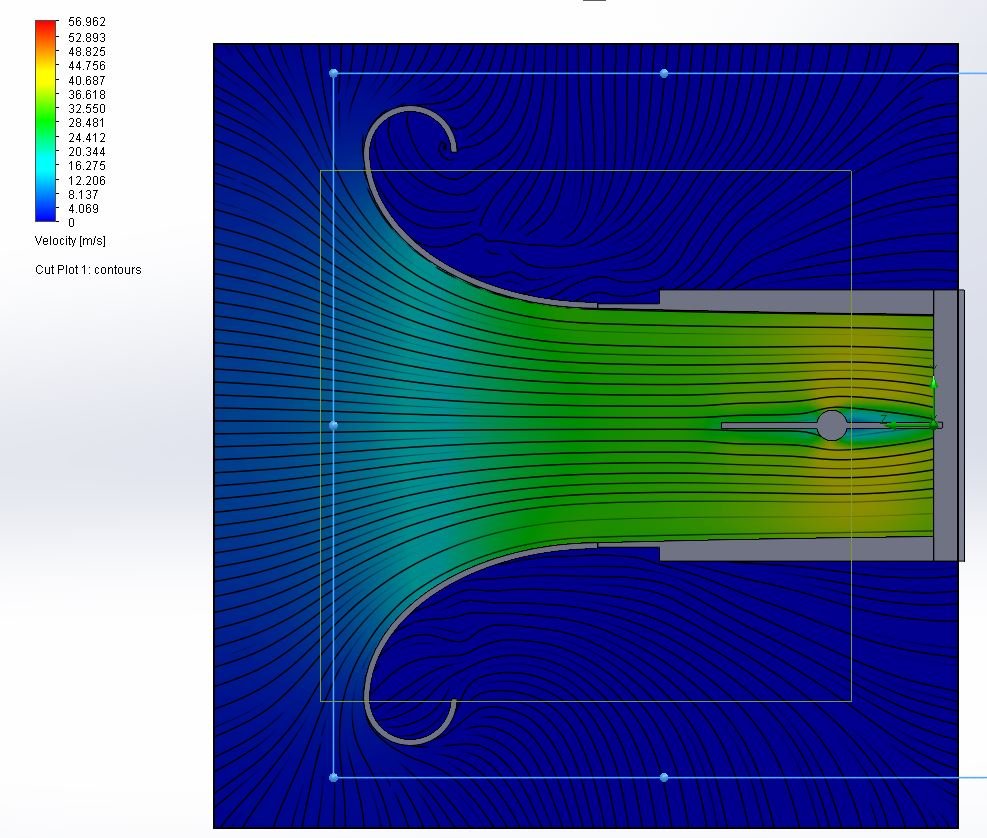
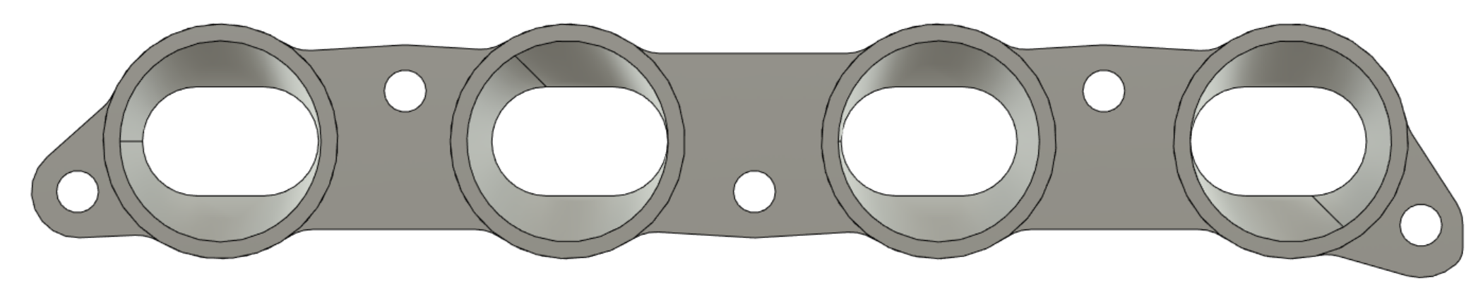
Version 2 underway. mounted 10mm lower and 5mm further into the runner. Then angling the injector about 5 degrees up I was curious how much the cross sectional area would be affected by having all this extra junk in the way. Taking a cut at what looks like the worst spot, and we've still got cross sectional area equivalent of a 74mm circle per runner. There's still way more bellmouth area than there was with the silvertop throttles.
 29 points
 -
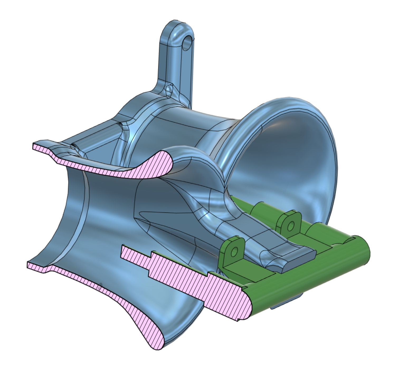
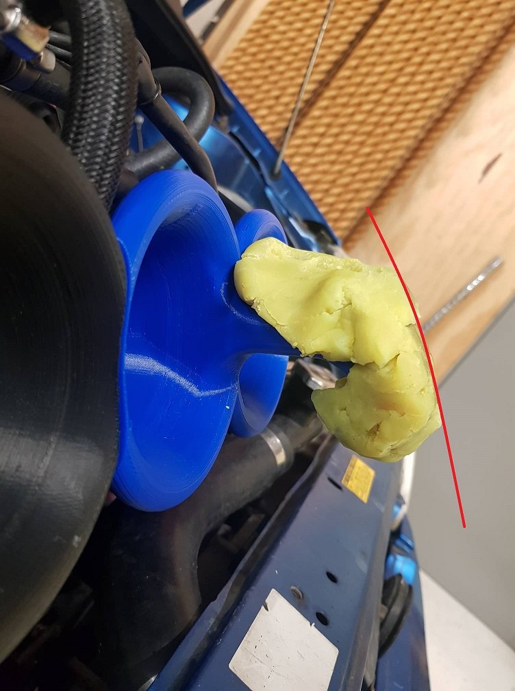
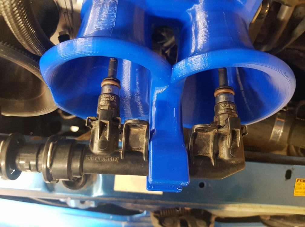
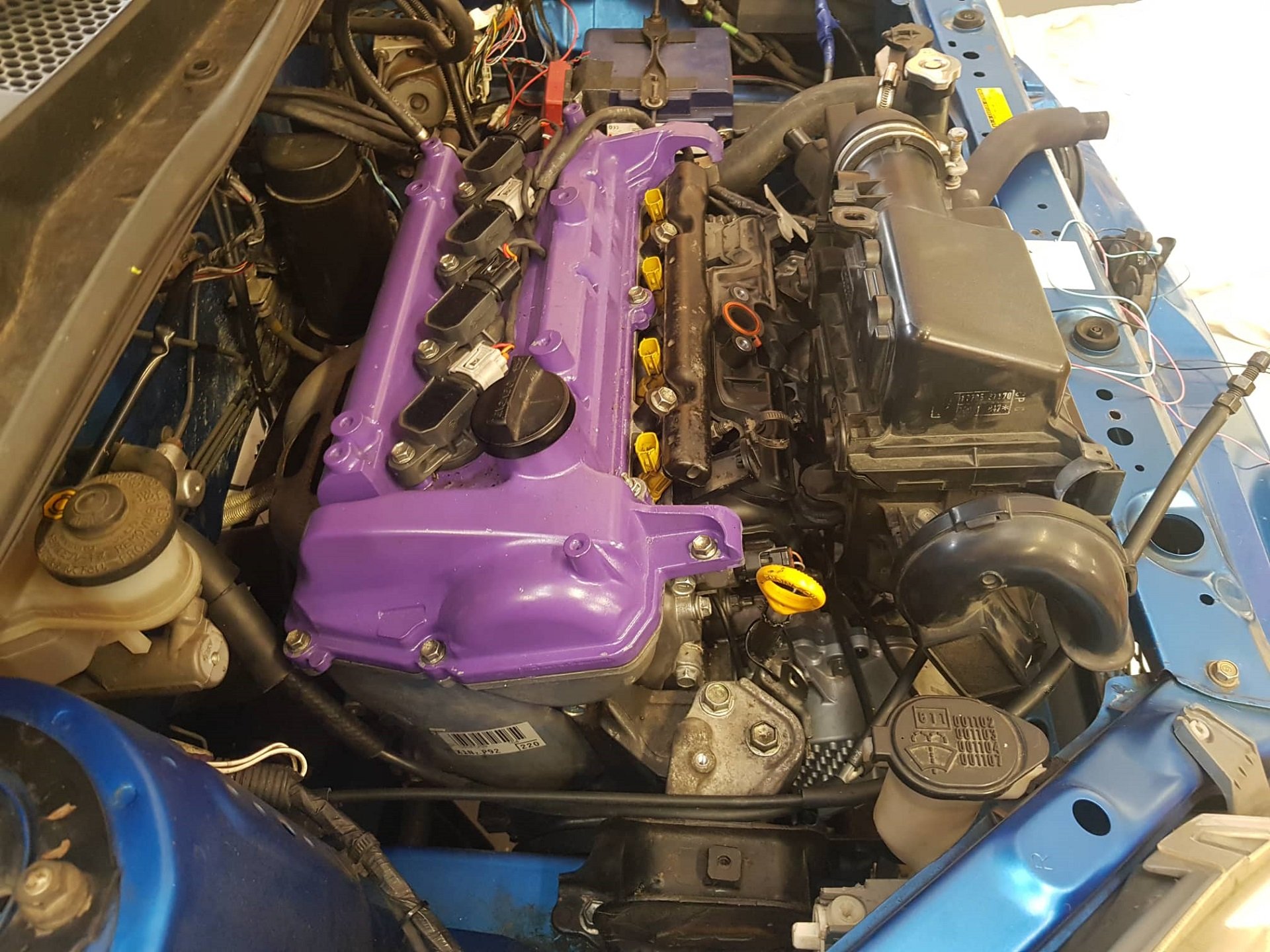
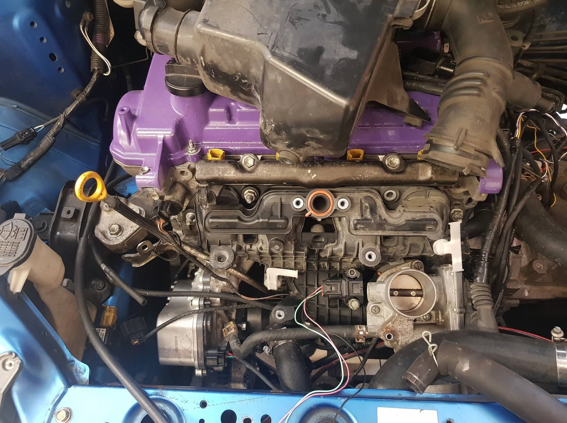
Injectors turned up so I made some progress on modelling up something to hold the 2nd rail. I've printed one half, unfortunately though this shape wont work as doing a clearance check shows the end of the fork thingy touches the bonnet slightly. But this is why printing is great. Once I see an actual model I find it easier to think of how to revise it to make it better. But otherwise looking okayish I guess The injectors could probably go further in if need be. But I think I'll just angle the bracket downwards and revise it a little to have more top side clearance. Maybe bring the injectors a smidge further in at the same time. For interest's sake (I've only got 4 injector plugs connected currently) I got the motor running with just the outboard injectors working. It actually idles fairly okay! I have to turn off the wideband fuel correction though, because the response time of the fuel reaching the cylinder is quite delayed. But for a full blown race car it would probably work alright. Once I finished playing around with this, I took the car out for a drive with just 100% running on the inner set of injectors. These are quite a bit smaller than the 450ish CC 2ZZ injectors, so the motor was reaching 96% duty cycle by 8500rpm. So a bit too small to run just on those. But I've got enough injector to do some back to back testing between innners and outers, and blending between a bit. I get the feeling that the factory inners usually point at the factory BMW port a little better than these ones do, so it might actually make sense to keep the factory port injectors. If so, I might try out the factory Prius injectors, which have I think a 12 or 16 hole pintle for super fine atomization. But only quite a small CC rating as well. So this might give some good fuel economy etc while having the secondaries for the bigger fuel requirements. Oooorrrr I might just end up sticking with 2ZZ injectors. See how it goes!
18 points
-
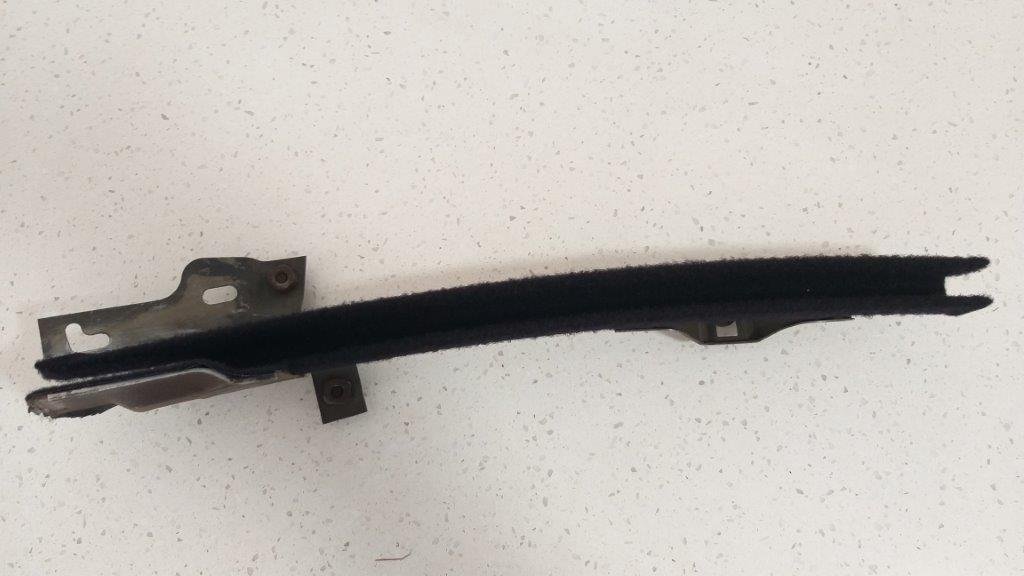
This morning I repeated the same exercise on the vertical window guide for the opposite side. Being the passenger one the felt was less stuffed but still looked well past it. Not that easy to photograph with my shitty phone, but you get the idea. I'm looking forward to tackling something different tomorrow. Ta for looking.
6 points
-
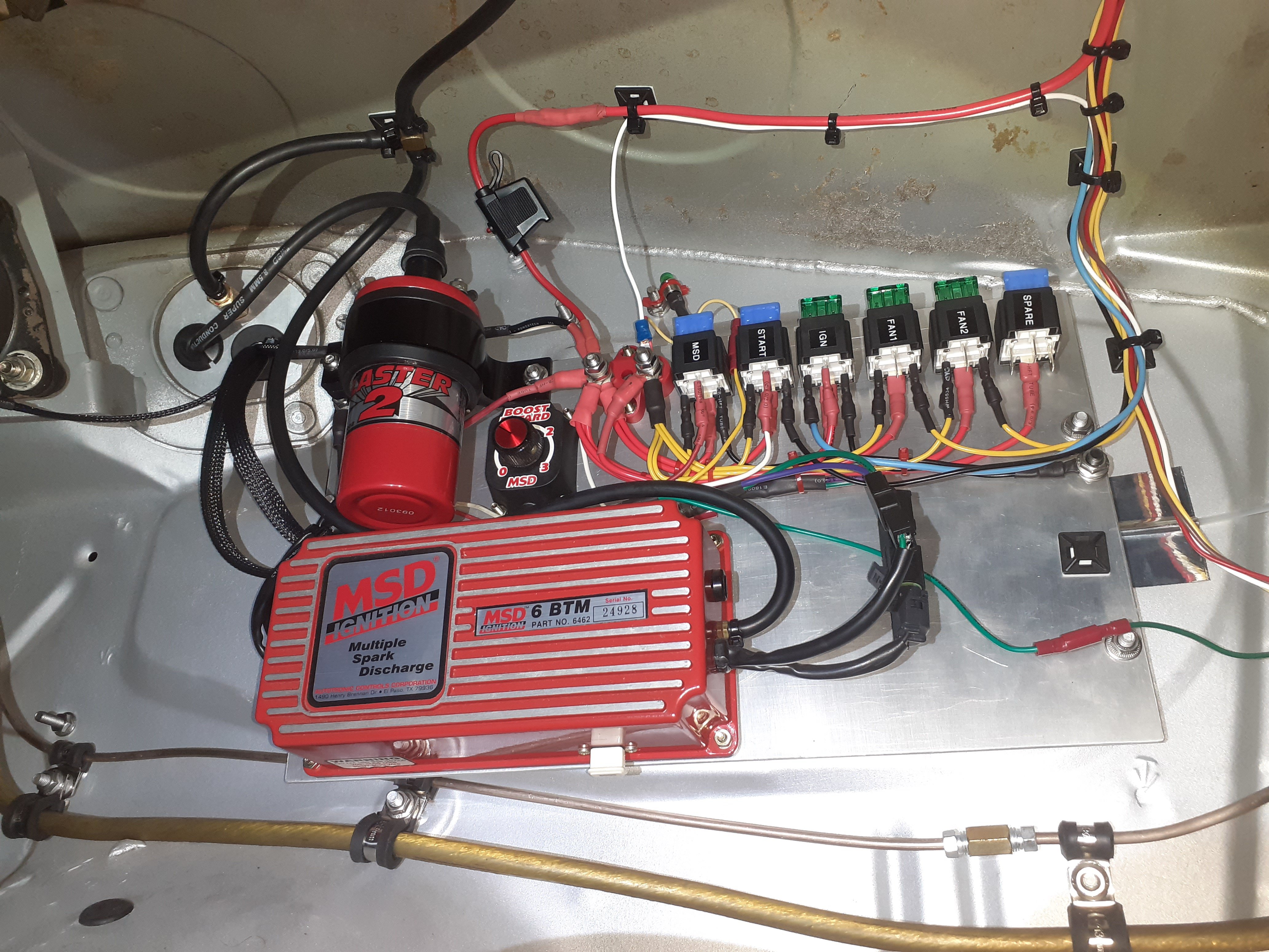
Doesnt look like I've done much but I've got 80% of the wiring sorted Everything I've wired so far works, and makes no smoke or sparks so I'd call that a success. And all the remaining wiring, I have a plan for, and know what goes where
6 points
-
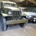
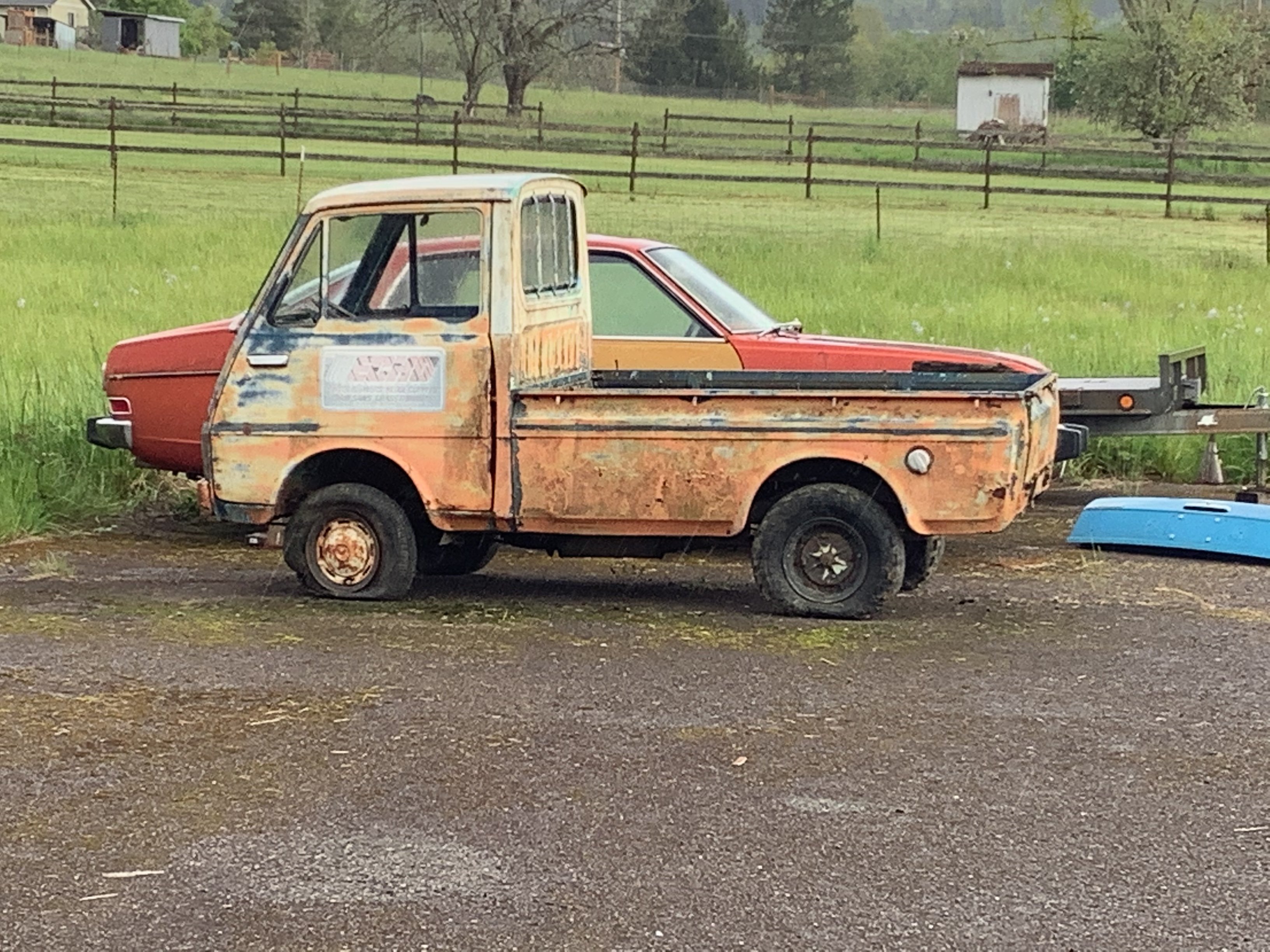
Impulse buy off FB marketplace over here in the states. I believe this to be a 67’ or 68’ S37. While searching for info I came across h4nd’s Fellow thread so joined up to ask some questions and he suggested I do a thread. Well, here we go. Truck is pretty damn complete but of course has rust issues. It’s pretty much the floorboards and bed floor, rest is not bad. Good glass. Supposedly *ran went parked* but that was who knows how many years ago. Doesn’t steer (sheared rag joint) doesn’t roll (tires shot) and doesn’t stop (hydraulics froze). I’ve got the brakes torn down and am in the process of rebuilding the system and tires are on the way. She’s a hot mess!
5 points
-
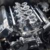
No idea, but I can do some back to back testing and find that out easy enough. Remember that most of the air comes from around the sides, not from straight ahead. Also the airspeed is (comparatively) incredibly low at the wide point of the bellmouth. Unrelated picture but you get the idea:
3 points
-
well I cut all the bar 1 tooth of the cam sensor..changed trigger 2 sync mode to CAM PULSE WINDOW and then just set that to 50° and she's now running both DRIECT SPARK and SEQUENTIAL INJECTION. she basically a modern engine now with classic pinto oil leeks.. haha not much else I can do till I make intercooler piping (and our postal service dictates when I get the stuff)... but even at idle the air coming out of the turbo is pretty significant. also set the water pump temp to 70° .. engine temp got up to 68° water pump kicked in...temp got to 71° fan kicked in and bought temp down to 65° in no time.... so I'm happy with the coolant system. RX2 70mm thick radiator, 14" fan in shroud ,electric waterpimp... on a side note ... heater was awesome within minutes. cheers
3 points
-
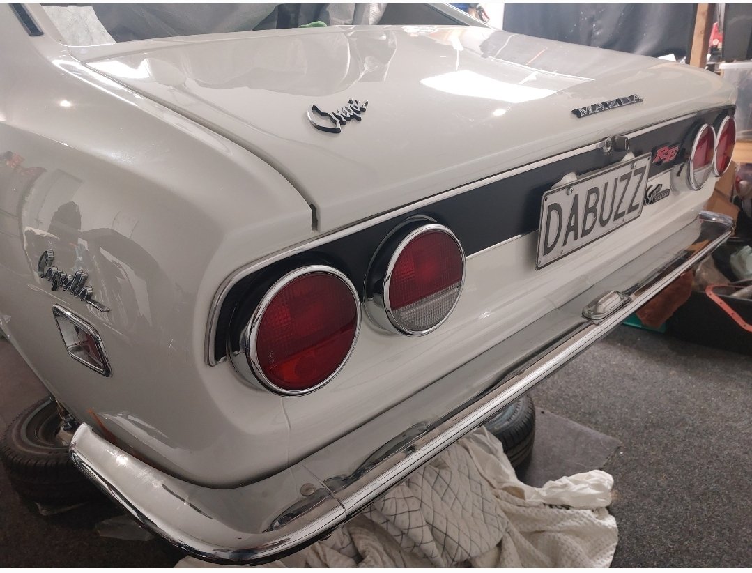
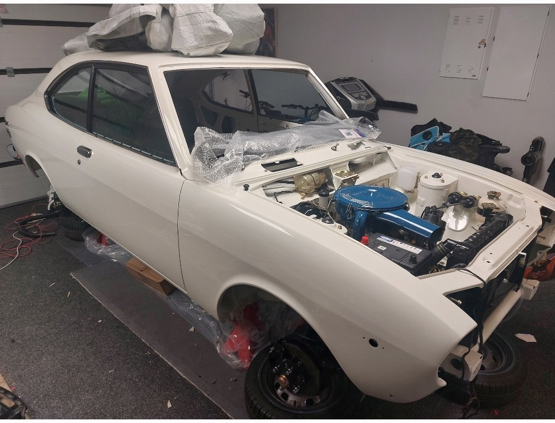
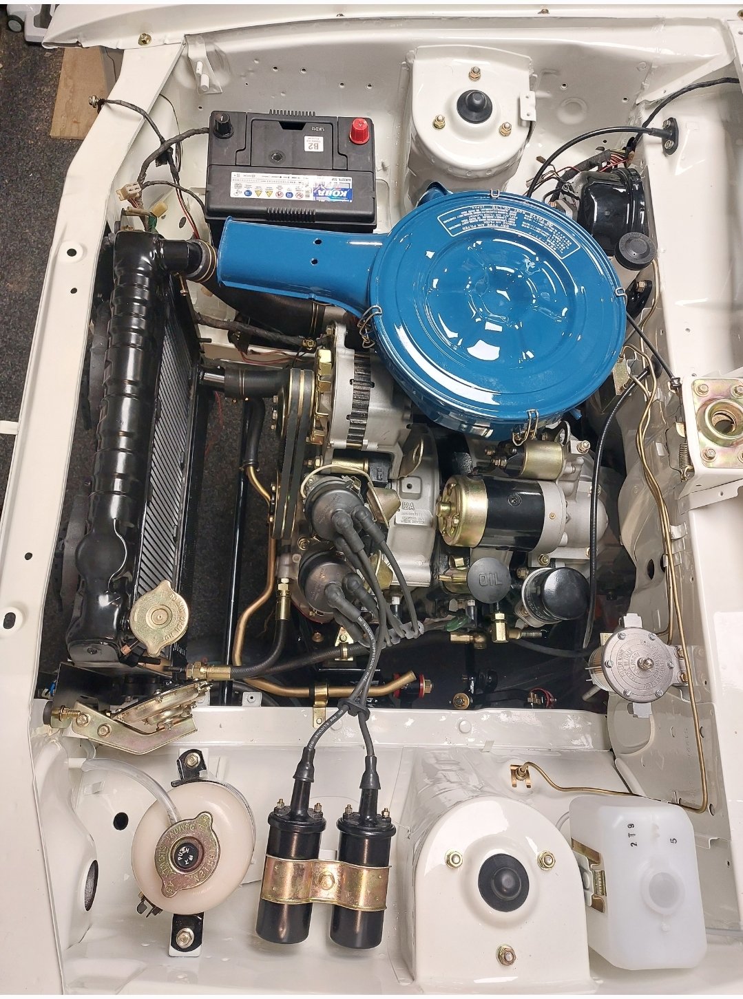
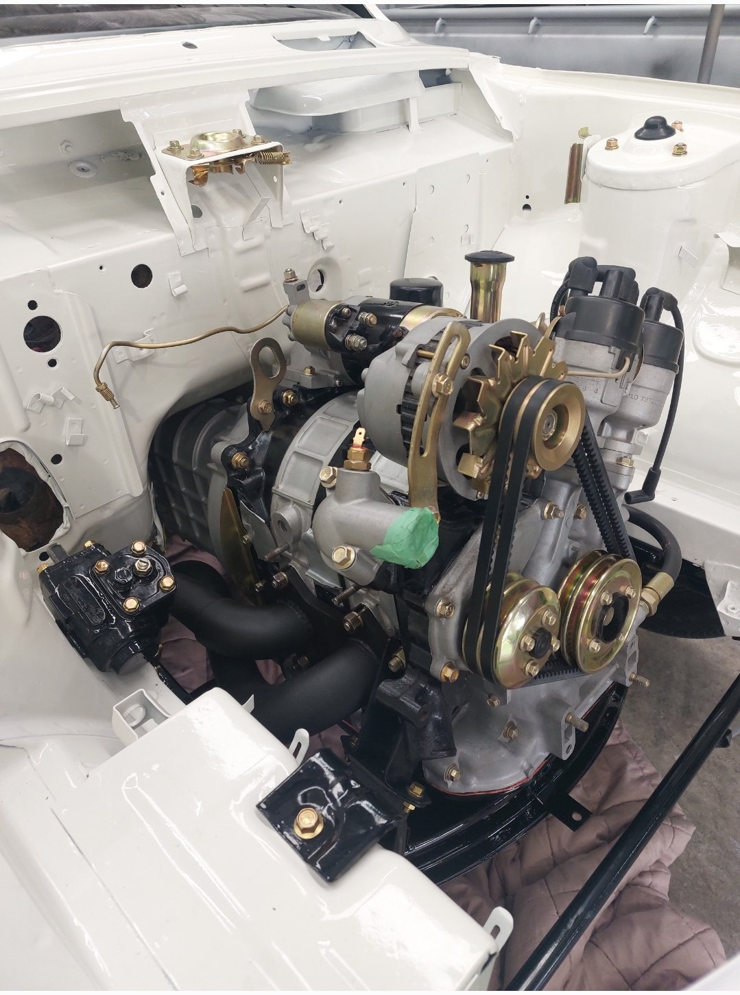
Engine bay well underway A few badges lights windows, chrome etc fitted too
3 points
-
None of the shit I blow out into the sink rusts, so I think this is the case Shower floor is pretty Rusty tho2 points
-
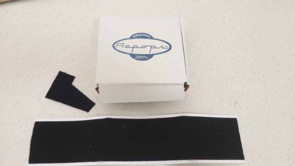
The next step is also a bit tricky as you need to peel the back off the adhesive and at the same time get the new felt perfectly stuck to all three sides inside the channel. Any lumps will be fatal as they will prevent the channel from sliding smoothly. I started by peeling one end, but it soon became apparent that this was going to end in tears so I ended up asking Uncle Google how best to do this and he suggested cutting the adhesive backing into three strips and then pulling the backing off the centre strip first. Used a carpet knife to carefully cut through the backing without injuring the felt. Got Mrs Flash to give me a hand and between the two of us we got it spot on. One down and one to go.
2 points
-
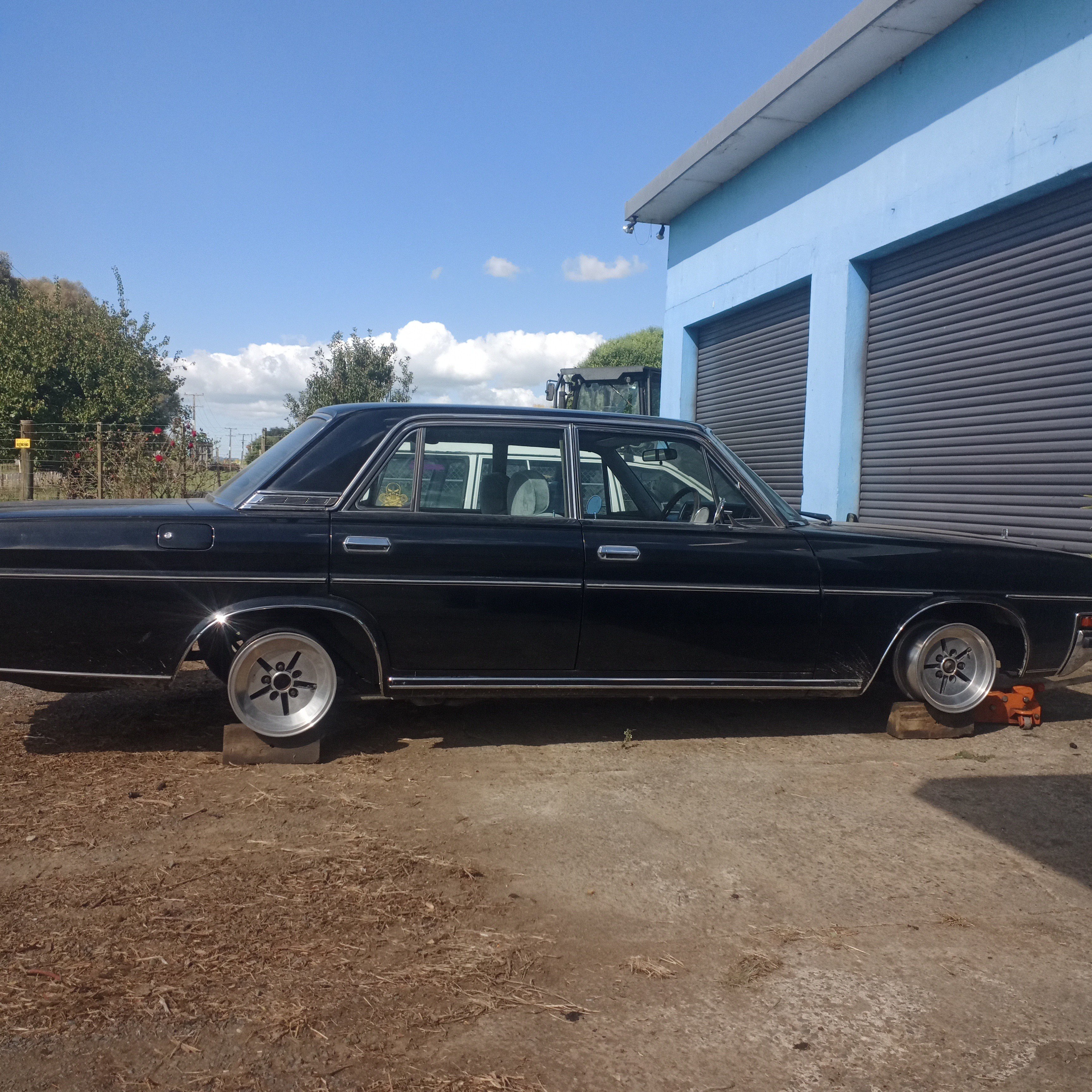
Played with wheels,
2 points
-
HQ is actually 5x120.65 / 5x 4.75” That extra 0.65 is enough to snap your wheel studs.2 points
-
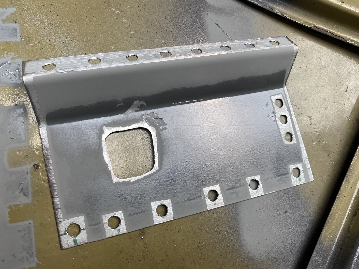
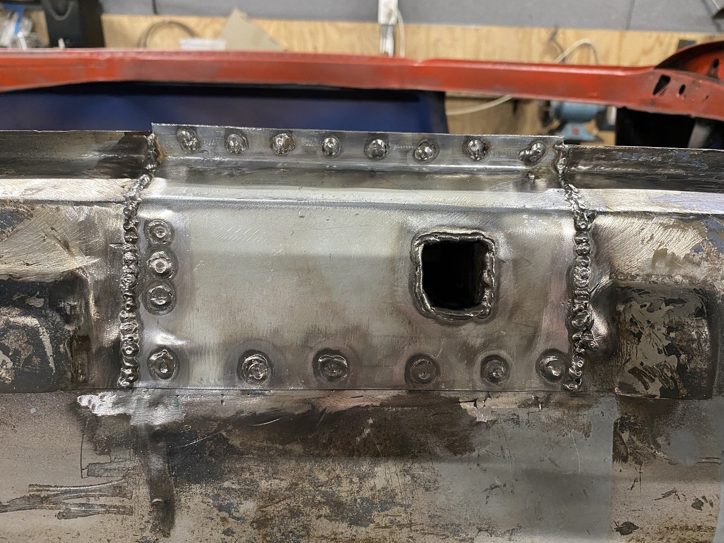
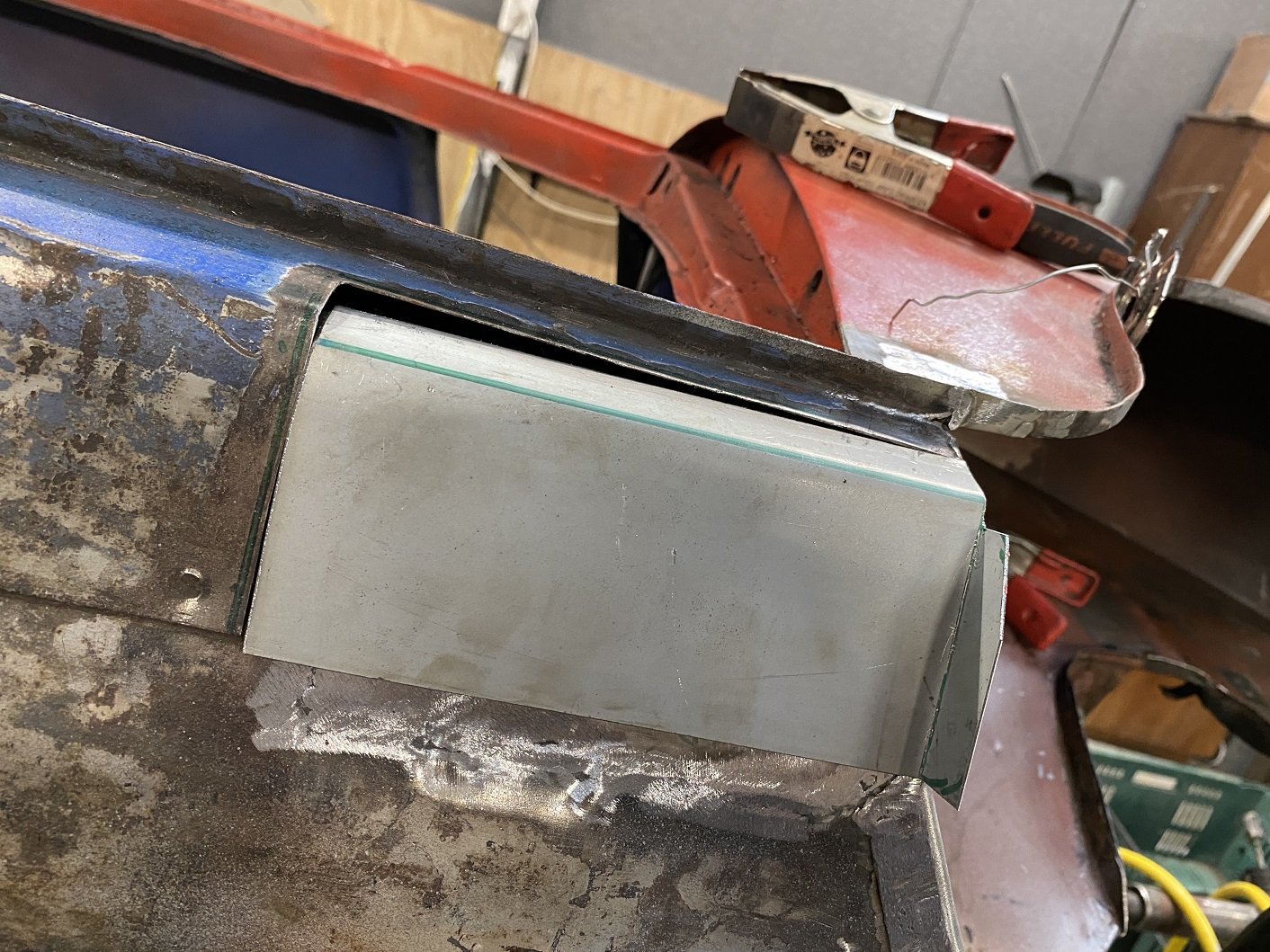
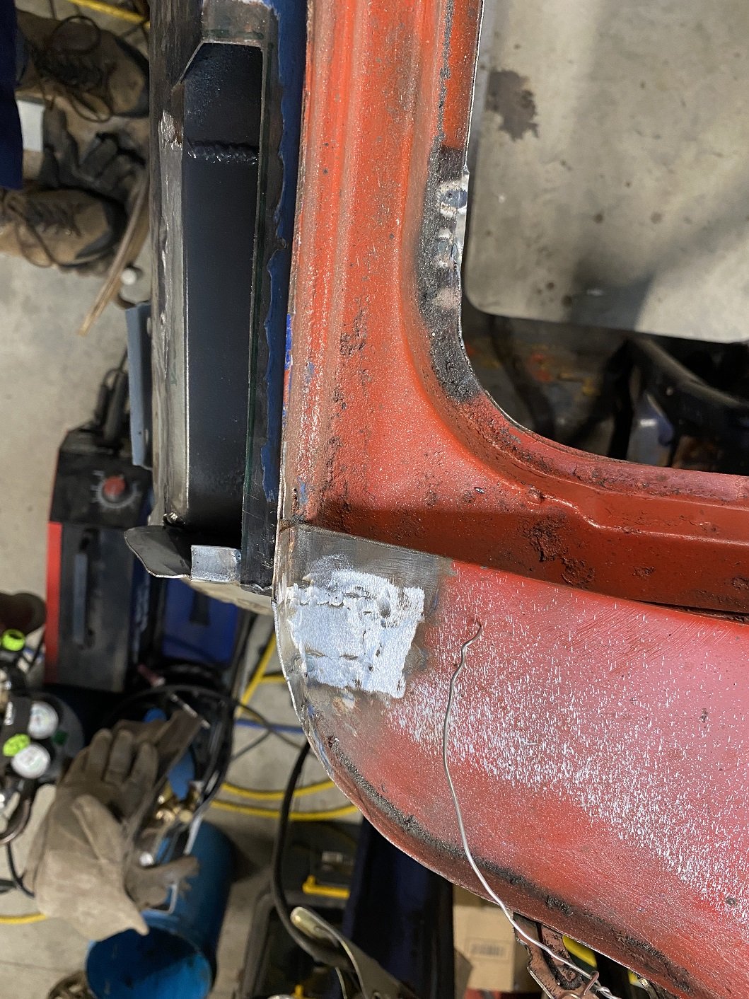
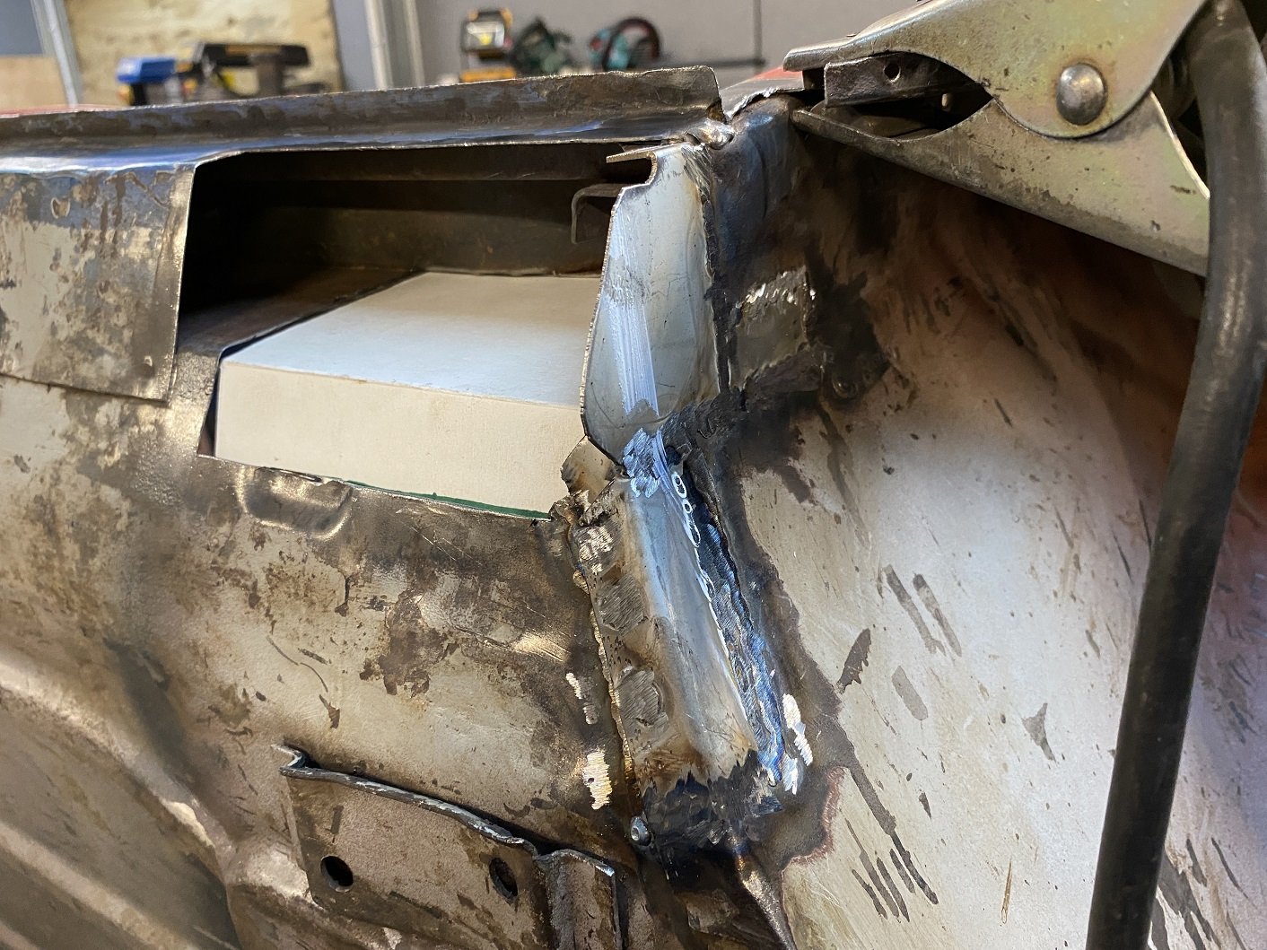
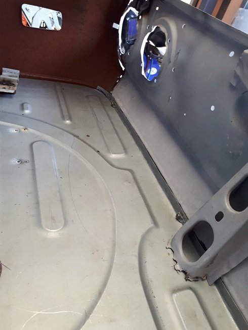
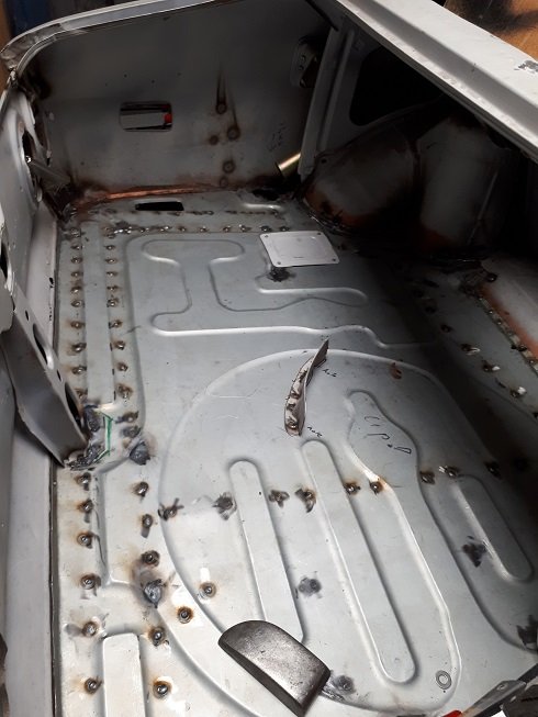
Much better. Just got to linish the welds and trim that edge. The other side jacking point has a reinforcing square around the hole... I doubt I'll ever use that jacking hole ever, let alone enough to dent the area around it... But if I don't add the reinforcing square, it won't match the other side....
2 points
-
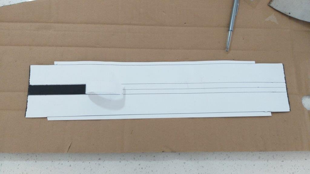
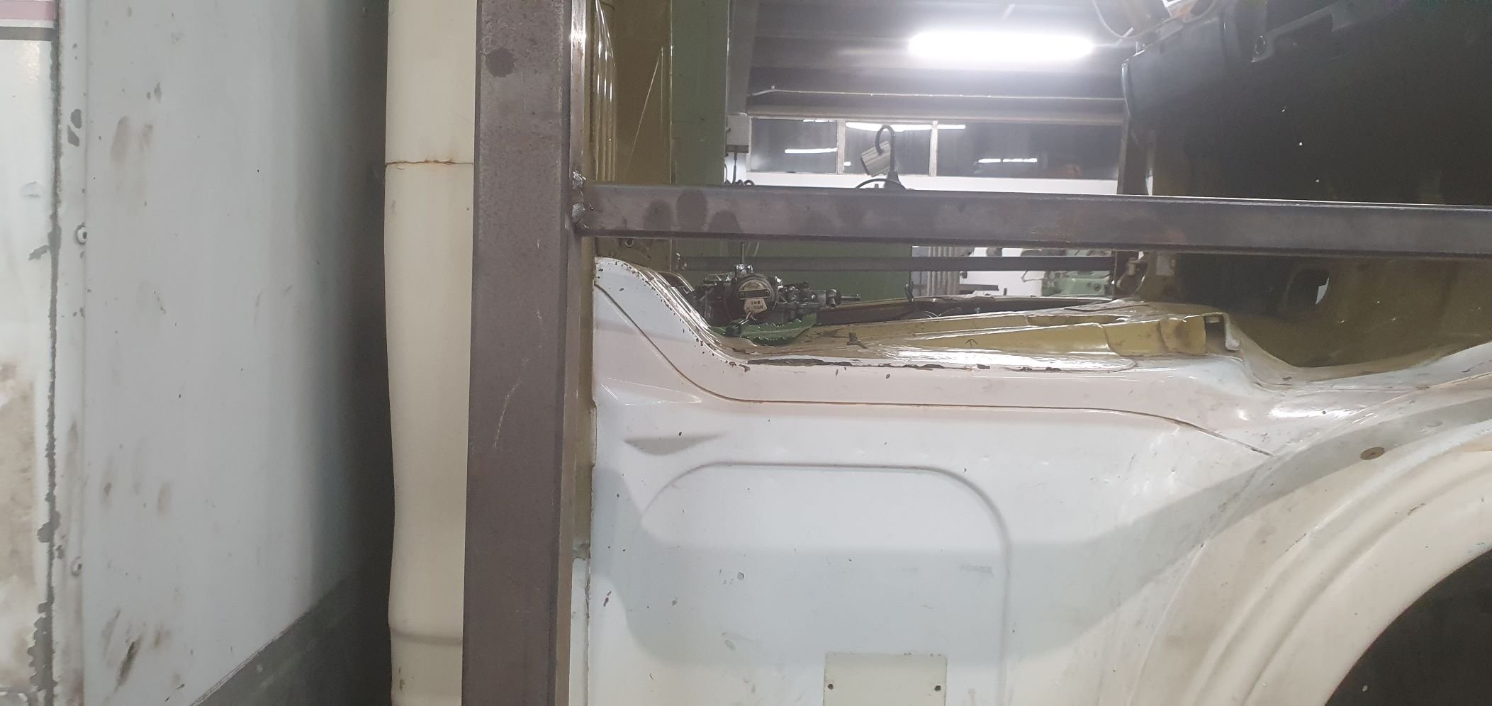
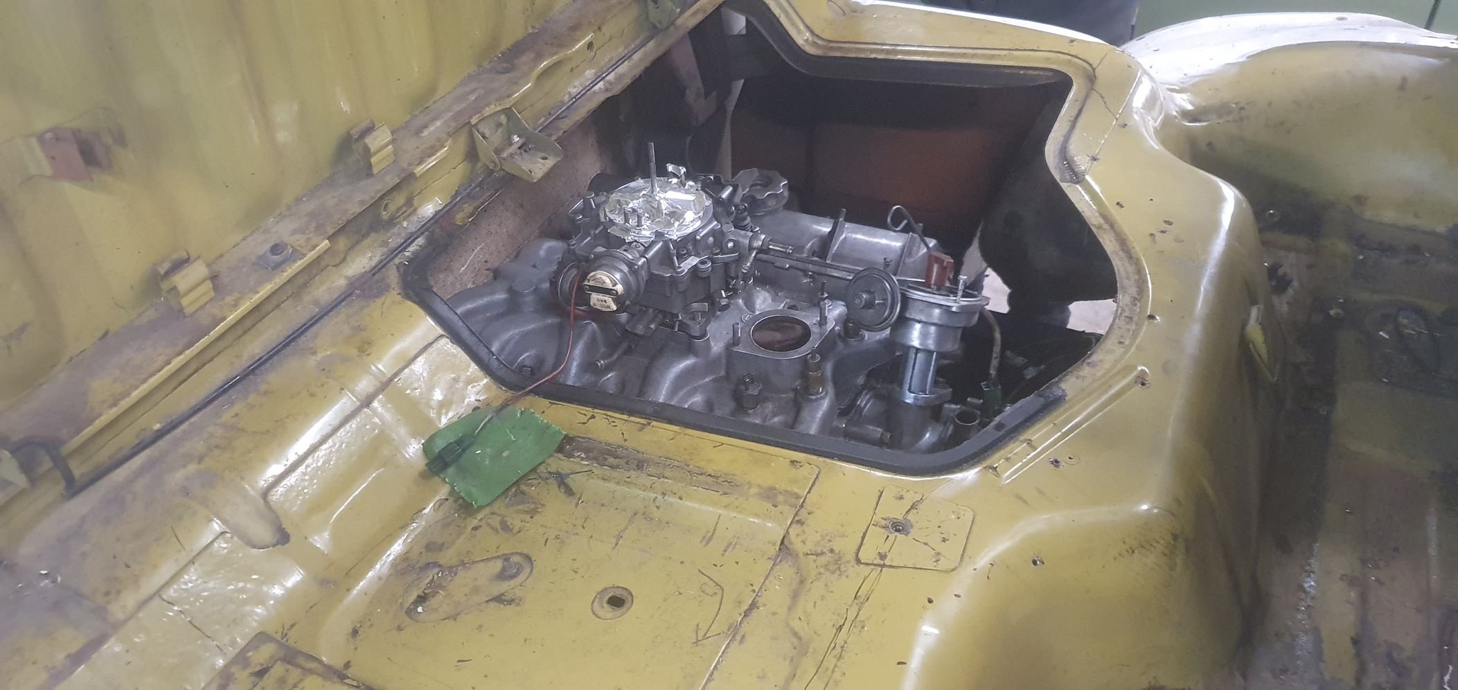
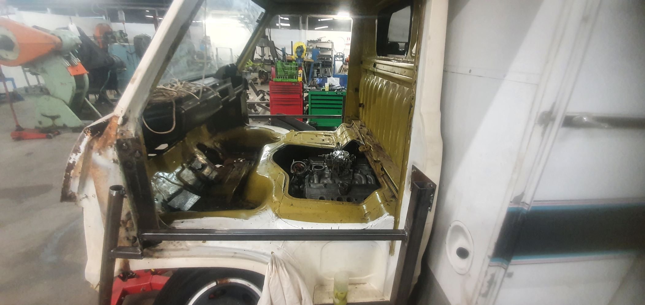
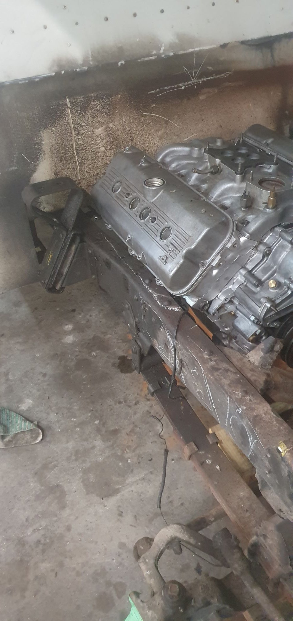
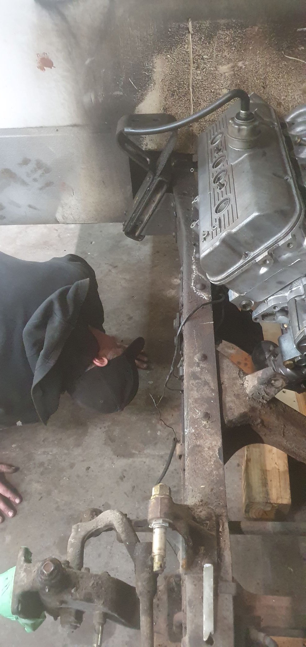
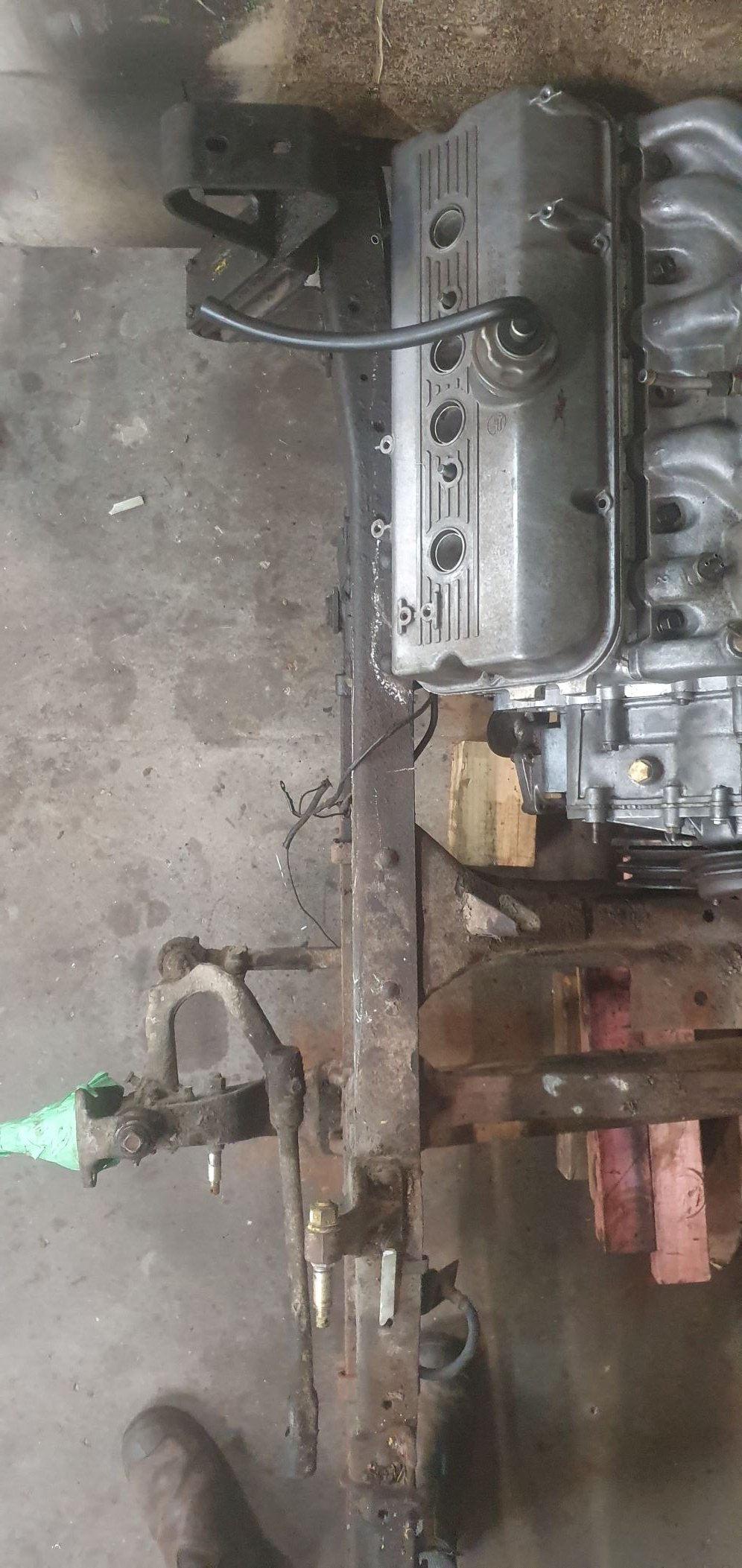
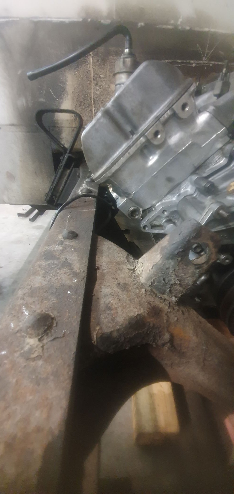
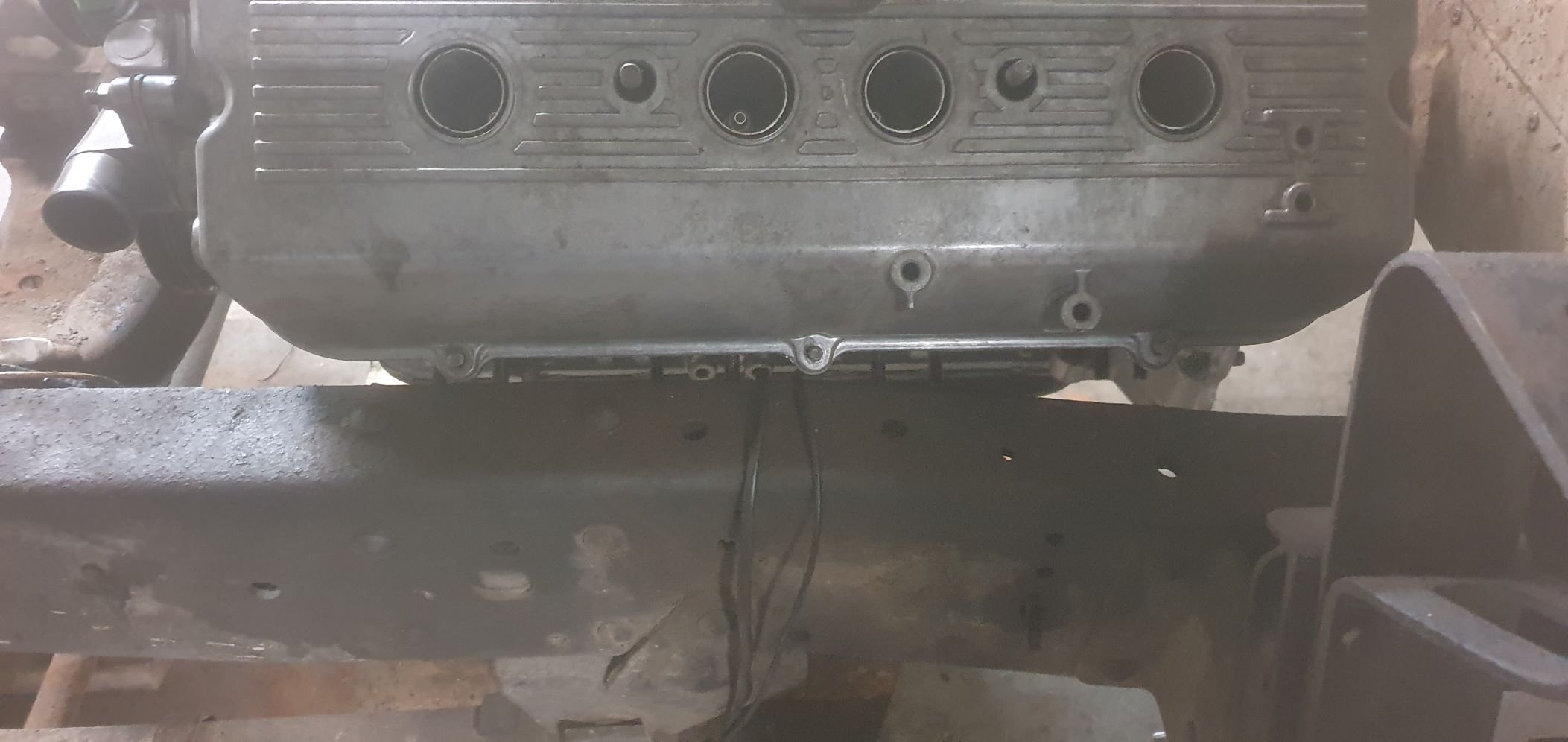
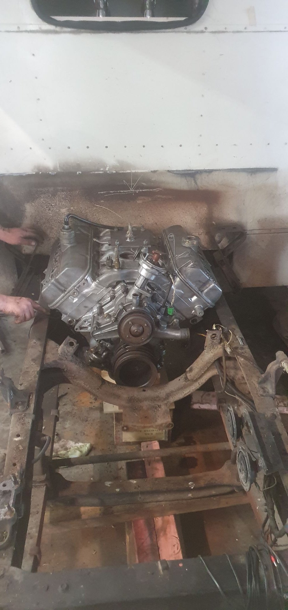
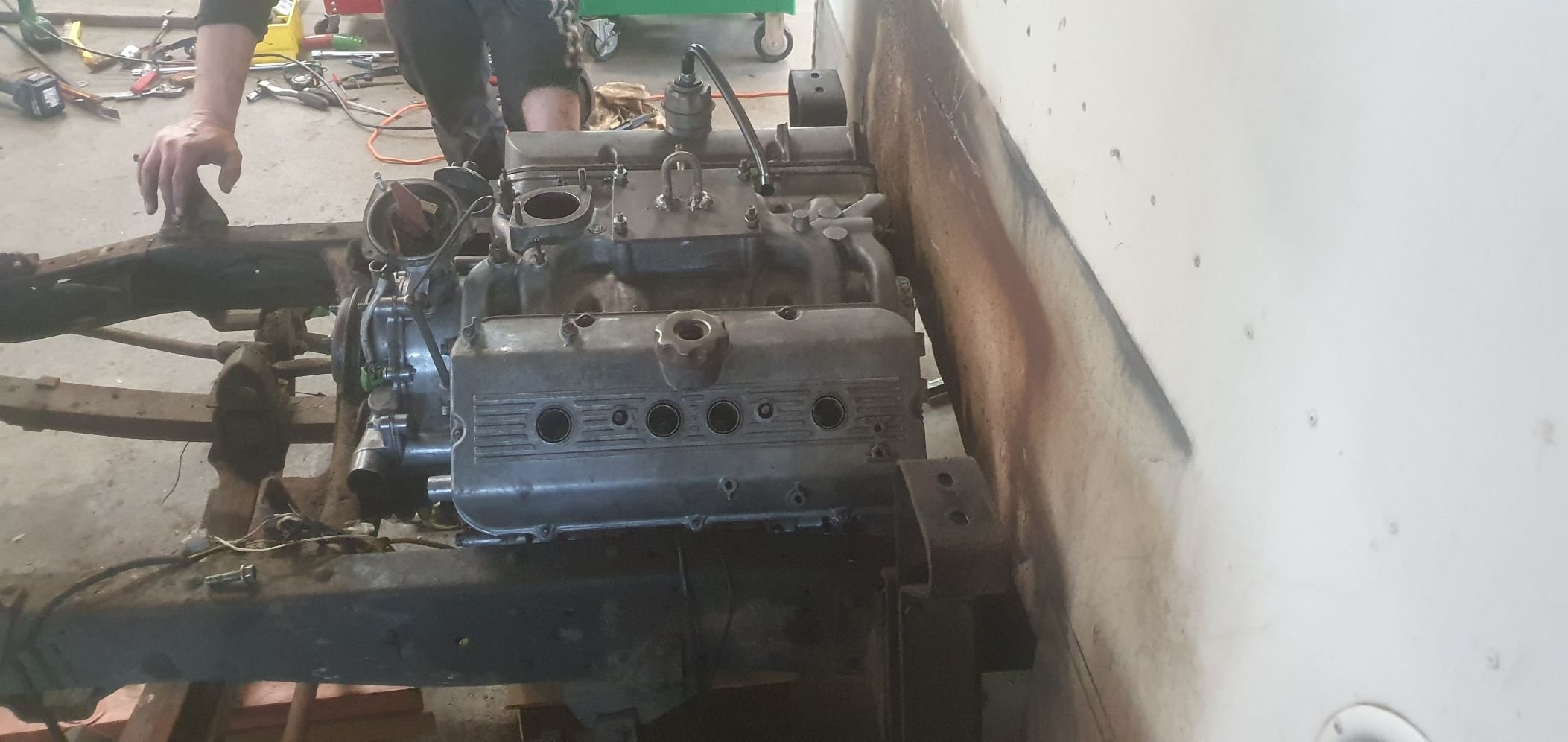
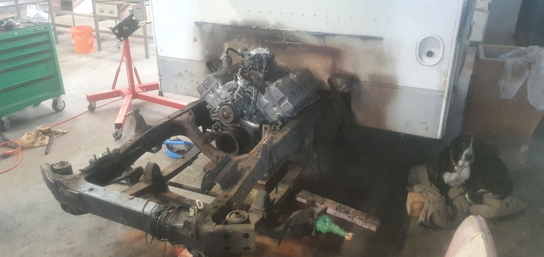
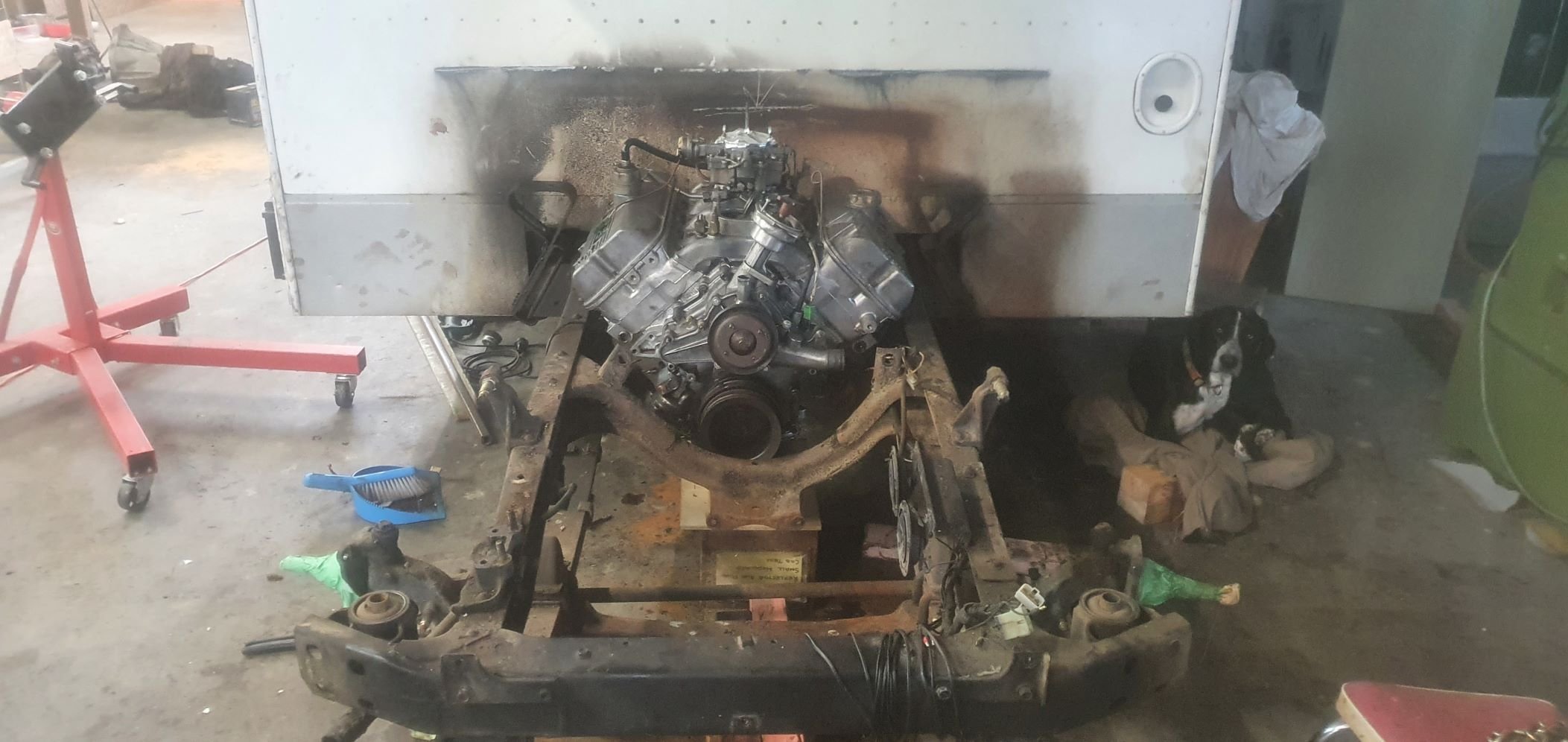
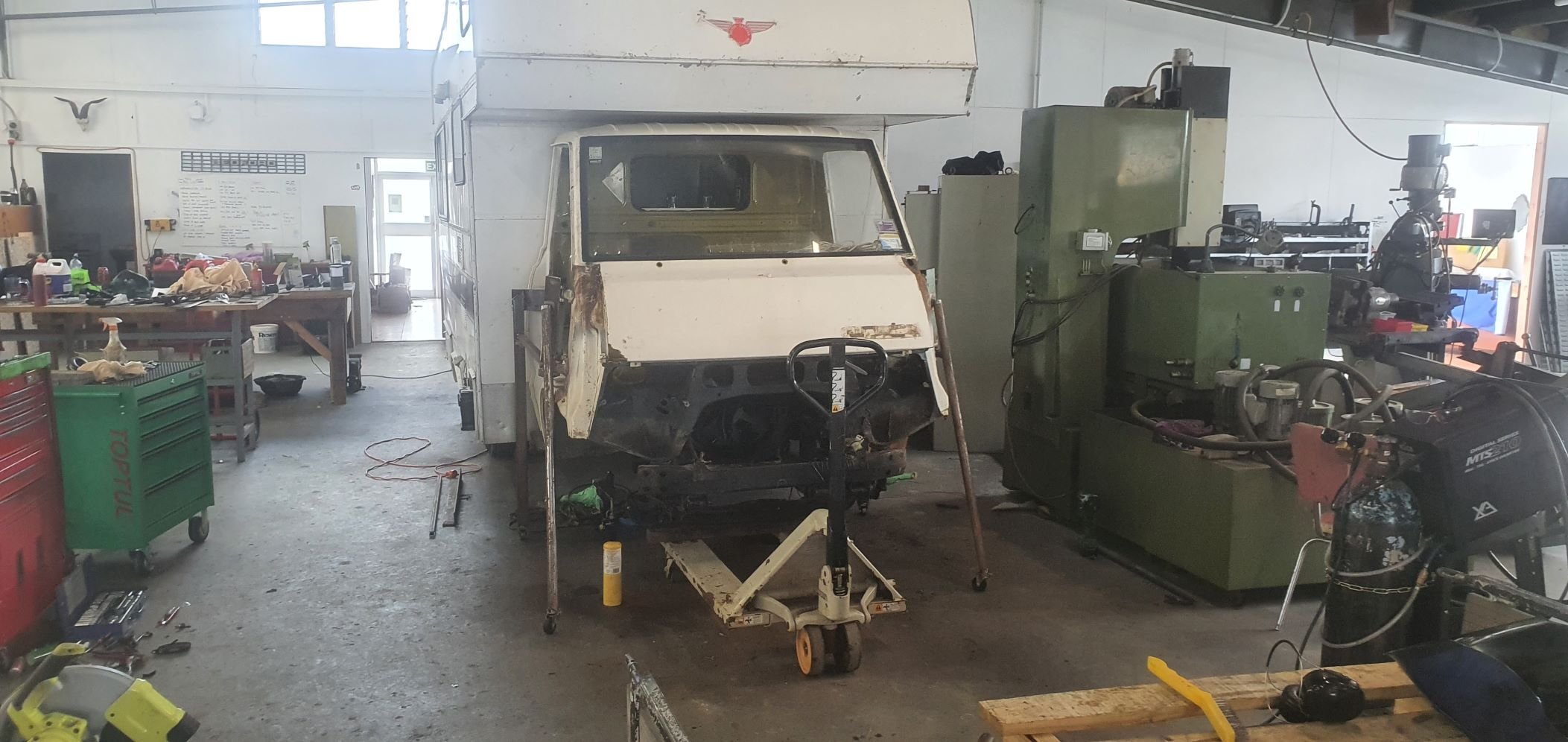
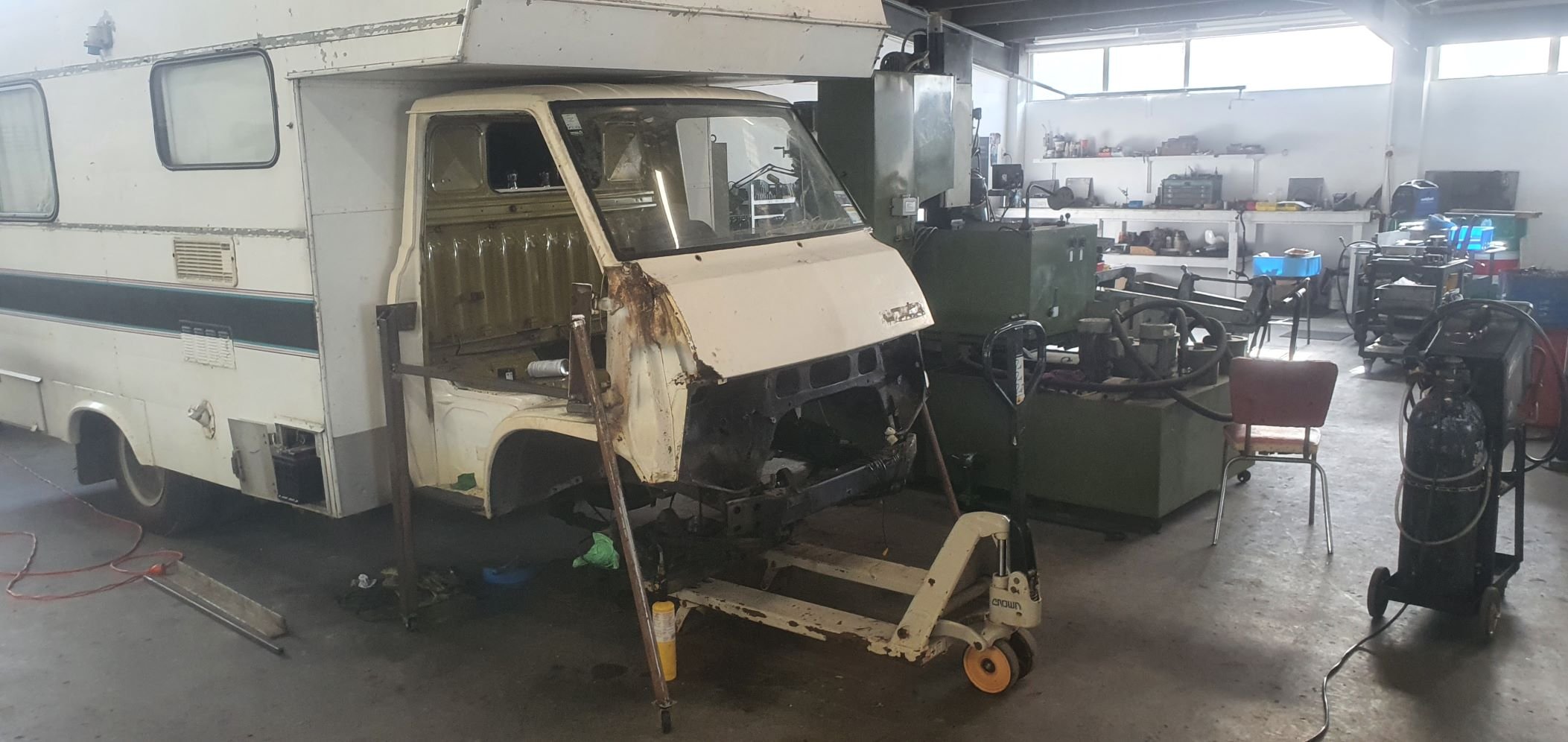
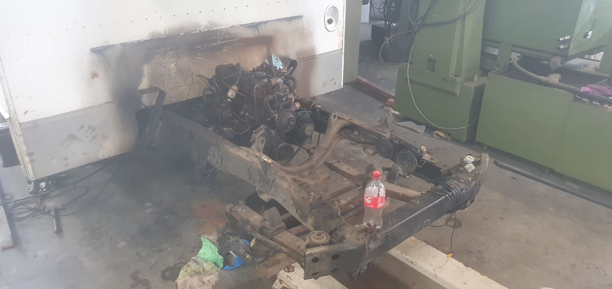
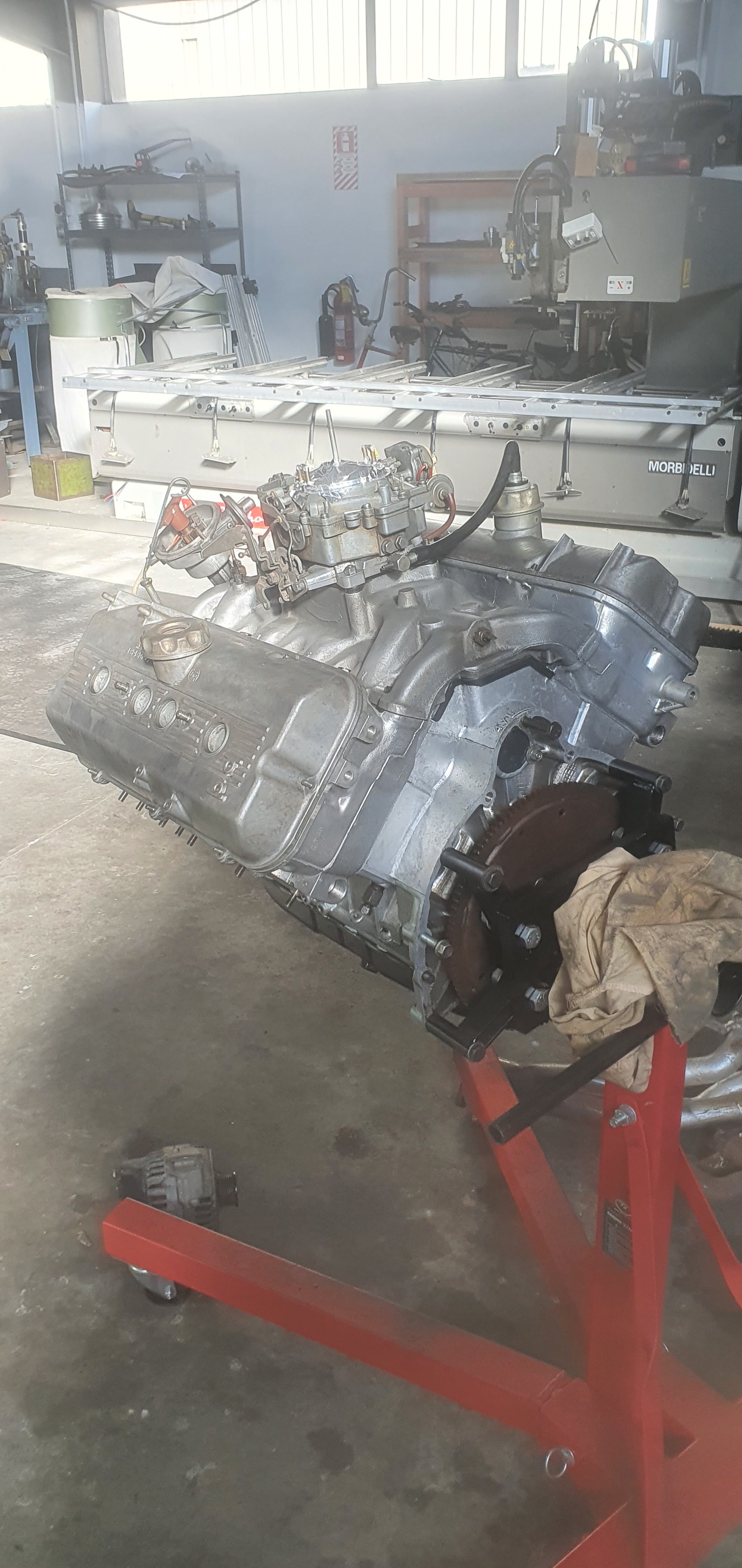
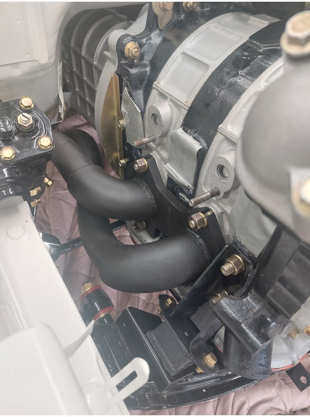
In terms of actual activity there is little to report, however the pondering, and opining from cunts like @ThePog and my worker - of near-equal cunt status - has been somewhat rampant. The main topic of conversation has over the last few days largely revolved around whether it is actually going to fit. It is largely a problem I have never encountered - just saying. So the motor has been sitting in the same position since we dumped it in there. I had to have a bit of a workshop tidy up. As many of you would well be familiar with, doing shit like this means sorting your shit out along the way and doing things in stages, so come assembly time you largely have all the shit in order, just requiring cleaning or a fufu can touch-up job. So I did that last night, and then suggested to Kyle that we wheel the cab back on, just to see (and to stop us thinking about the actual problems below). The carb had to be lifted off the engine to wheel the cab back over. But my oh my, doesnt it look pretty in the hole. Confirmed, It is Gynormous.. Also confirmed, the fucking thing is going to live in that hole regardless. Chassis chop, mid mound, fucking whadeva G. Every other possible engine option is shit in comparison, so that bit is solved. Now I need to solve the actual shit of ensuring whatever we do doesn't result in either a basket case chassis-hack job that will never be legal, or someones lunch being sucked out through their asshole by virtue of the carburetors somewhat prominent position inside the cabin. See pics - it is not optimal, the engine must go down in order for the carb to actually clear the engine cover and/or seat. The chassis rails actually widen where they pass under the camper body, and if they were that width in the engine bay we would already have that cunt mounted and half wired up - but alas that is not the case... So the present possible solutions are as follows; Option 1 - slice a 30mm ish slither out of the inside top of the chassis rails (removing some of top leg of C-channel), effectively continuing the inside line of the chassis rail (under camper body) further forward through to where the front of the engine is, then stepping in (see chalk marks). Then strengthening the Chassis with another plate on outside with folded edge to reinstate the 'beam strength' back into the chassis, or adding other folded piece over top extending further rearward and forward (kindof boxing the outside) This would allow the engine to drop down and maintain the current position. Tight set of log-style headers, removable from below should be achievable. FYI, Im an Industrial Designer by trade so drawing up, profile cutting, folding some shit, fabbing and modding the rails doesnt seem a terrible idea to me - but there are obviously rules and my cert man has already advised his 'preference' is for not modding the rails. I feel a CAD model is needed just to communicate my thinking further here.. Option 2 - start hacking out the camper body - this is effectively the area at floor level under the sink - possibly the most useless space in the entire camper. Making a removable section and shifting the motor back far enough (prob 250mm max further rearward of current position or roughly half of the engine under the camper body. Driveshaft gets rather short, as believe it or not the wheelbase of this thing is a tad under 3 metres. This area will need a massage anyway for the trans, so there is some logic in cutting here now and then reinstating removable infrastructure later for trans access etc - regardless of where the engine ends up - ie it would allow us to fully entertain that possibility. Doing this means the engine slots between the rails somewhat easier, but obviously engine access becomes more limited and opening the engine access hatch means the engine wont really be that accessible (prob dipstick, dizzy etc access but little else). And it will look weird - I like the idea of opening that hatch and there she is in all her glory.. Added bonus is there will effectively be a 'Frunk' under the seats where the engine once sat... Option 3 - the oldschool hivemind give me your opinions on my discussion thread - maybe there is something I am missing here. Its hard to communicate how tight it is, hopefully the pics below tell the full story. Be great to hear others thoughts on what is possible here - I am actually also thinking of talking to one of the local Truck Chassis mod dudes too - given this thing is actually just a truck.. Chur.
2 points
-
Spotted by journos.2 points
-
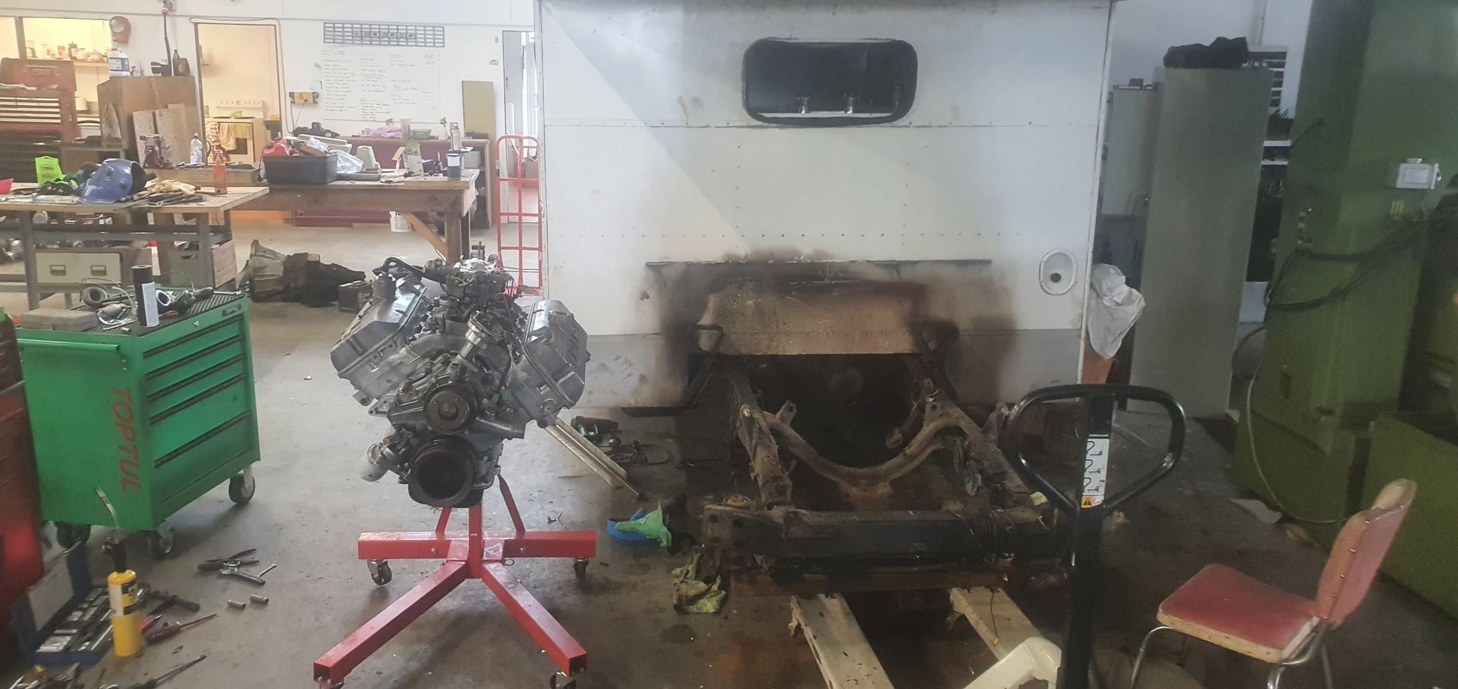
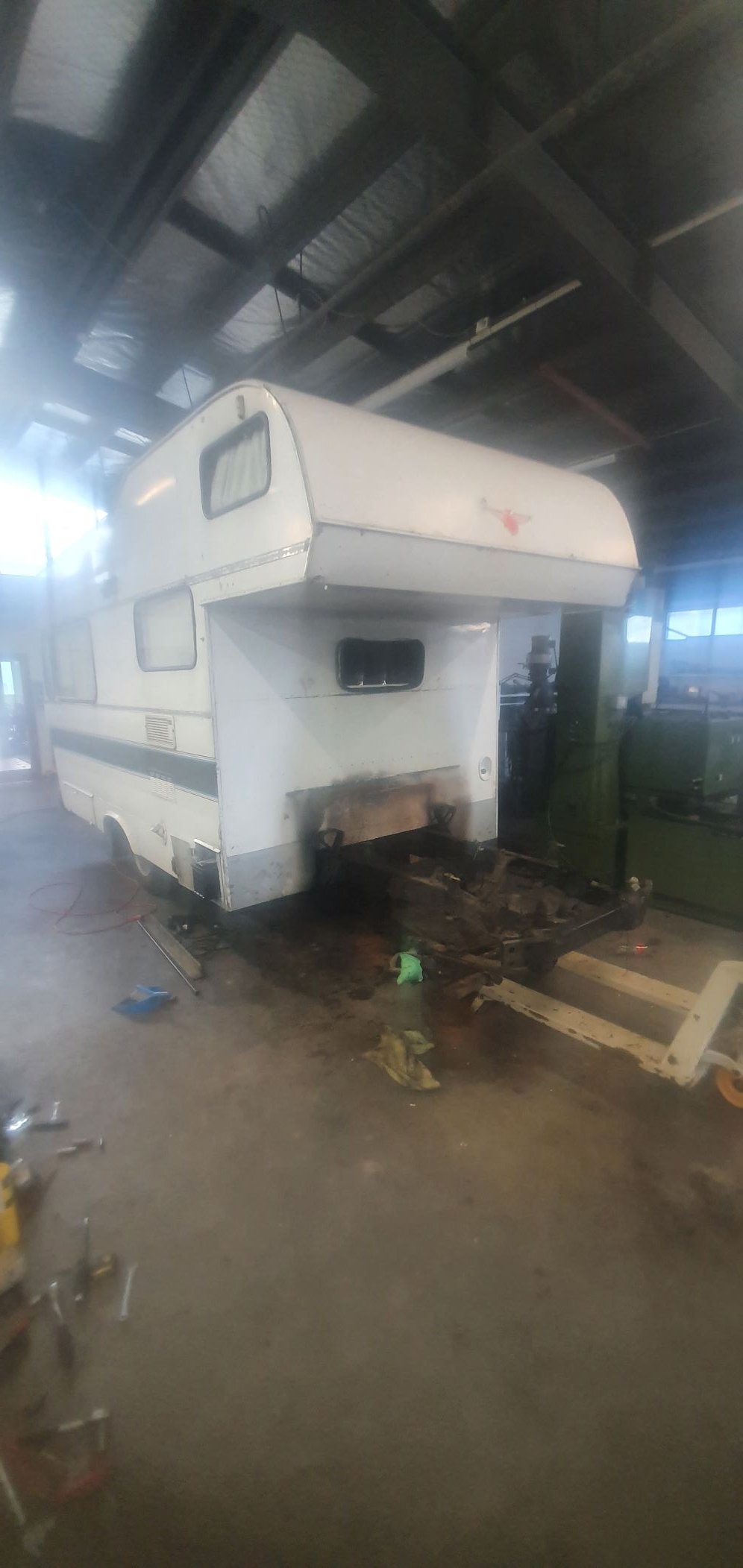
Got Impatient/bored with work today around 3pm and wandered out into the workshop, decided to poke it in the hole. No amount of tape-measury can prepare you for the shear girth of this thing. You think you have room until you are trying to jam a 4V into something. Fuck me there is some thickness there. Chassis needs to be chopped....... actually at this stage fuck knows, time to talk to the cert man about what options we have. I havent fit the cab back over it to see what wriggle room we have, but suffice to say it needs to either come up (unsure if possible without losing the middle seat...), or the top edge of the chassis rail needs some massaging. Either way its tighter than tight thing. It looks fucking cool in there, I really hope I can make it work. If I cant Im turning it into a caravan and towing it with a T-bucket fashioned from the remains of the cab with the motor in it - its the only logical maneuver The way I saw it in my head was I would remove Cab, engine would drop in, sit perfectly where I wanted it and the factory mounts lined up.. I may not only be a cunt, but an unreasonable one. Watch this space I guess, the next bits become infinitely more difficult and time consuming...
2 points
-
A Google search I did after learning of them said they can improve fuel economy too. Given on rock auto they're a quarter the price of what youd pay for iridium's here, 8m thinking why the fuck not?1 point
-
that's exactly what i was wondering next? would there be any restriction/turbulence with this in the bell mouth?1 point
-
Bro fully appreciate the input, no offence taken.. Will consider further.. May still pursue irrational option.1 point
-
Ive been using dust masks for the last 10 years now, after I started working on that Bedford cf project. I was noticing how much dust etc I had in my nose at the end of the day. If I ever even grind something for a few seconds without a mask I quickly note how much stuff I'm breathing in. Or you see the stuff floating about in the air when grinding in the sunshine. I figure all the metal drops to the floor so what we are breathing is the fine dust from the epoxy that holds the disc together? @sr2 Vauxhall Viva hbs have a really nice gearstick gaitor you might like.1 point
-
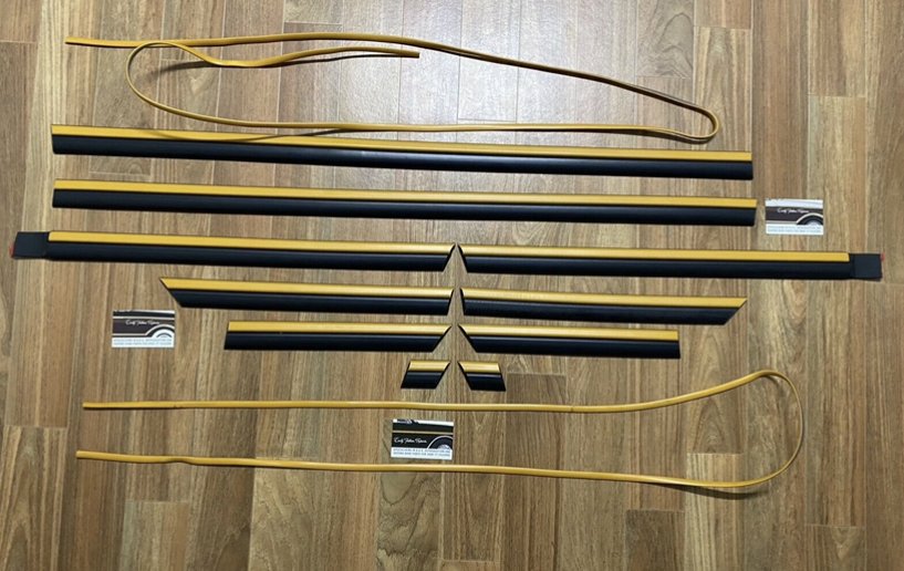
I couldn't find my bonnet cable clip so pinched it off the blue van and made a replacement. Could have used a cable tie or p clip but because it's visible I didn't want it to look too out of place. I'll have the old black one stripped and anodized.
1 point
-
Love all the trims and badges - Great stuff!1 point
-
Looking epic man!! So good.1 point
-
If only everyone just took my advice like that the world would be a better place. For me. Cos I'd tell them to all fuck off and leave me alone.1 point
-
It was somewhat depressing to learn today, when peering under the bonnet of my mates HQ Statesman, that an engine of near double capacity (ie a SB chev) is about 200mm narrower than this donk. Todays Fun fact.1 point
-
If there isn't much force on the reverse motion, could just weld some nuts to a tube and tighten bolts through them onto the shaft. like this1 point
-
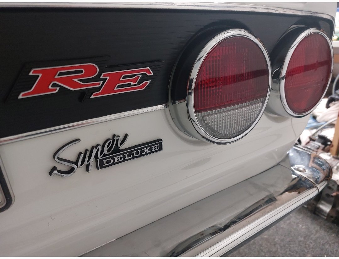
With the rear panel being modified to take late model mark II tail lights I doubt the matching garnish that houses number plate and number plate lights would fit so I'm going to take the opportunity to attempt something similar to this Inspired by Instagram user alkku_ Mine will be a bit harder due to inner inward edges on x6 tail lights having a beveled edge not 90° with the top bottom. Hoping to use two spare lights and slice them in the middle and get the bevel right on outer then glue them up
1 point
-
Been to see the certifier. Went very well. He suggested a few things such as redoing the brake pedal to meet the standards but nothing that's hard to do. Belts in it should be fine as there is an easy mounting point available and some pointers about the fuel tank and it being in a safe position, i.e. inside the bounds of the steel chassis and not sitting in the timber/aluminium only tail! But all of those are easilably doable. So all good now to start on the framing/body. That's a big relief. Simon1 point
-
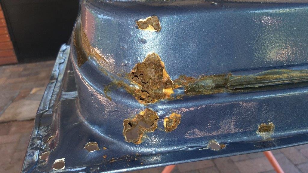
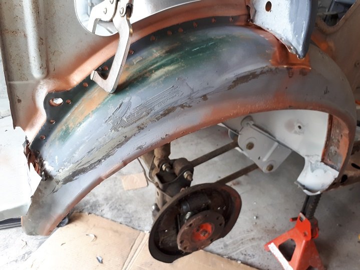
And then... I know it's not really ideal to be painting over the existing surface rust. But some Zinc It has got to be better than nothing at all. I'll shoot some penetrol and cavity wax in there once it's painted. I'm assuming epotec epoxy primer won't stick to the penetrol.... but I want to use something that will creep into all the seams (that 100% will have rust in them) before I seal over them with epoxy.
1 point
-
The cooling system is gonna take a few revisions to get spot on I expect, I'll put it together with what i've got and see what it needs before spending money on new bits. Things I don't know, will it need a bigger rad?, will the bike waterpump cope?, will I be able to get all the air out? etc etc The stock setup has two hoses running through a tunnel in the floor to the radiator up front, the hot side goes through the heater matrix first then a bypass thermostat before the rad, there is also a header tank in the frunk which takes an air bleed from the thermostat on the engine, this runs up the c-pillar through the roof channel, down the a-pillar then into the header tank. Interestingly it has no fan on the radiator, the heater fan performs this duty as all the hot water runs through it anyway. I'm mostly replicating the stock setup, due to the height of the engine the header tank and overflow will be in the back now so they can still be the highest point in the system. I'll also be adding a radiator fan and after speaking to the radiator shop I'm gonna ditch the heater for now to help with flow and will also cool the oil with air instead of coolant. So starting in the front. I had to buy 7m of 25mm ID hose to replace the 50 year old originals. Chopped up the heater box as the bottom was rusted out anyway The hose now goes straight to the bypass thermostat housing. The benefit of keeping this setup, as I read on an MGF forum discussing headgasket failures, is that it helps stop temperature fluctuations in the engine by warming the system up in stages instead of repeatedly flooding the engine with litres of cold coolant whenever the thermostat opened. I need to make a trip to supercheap sometime and rummage through hoses for a better upper rad one, one join would be ok but two with different colour hose looks a bit michael mouse.1 point
-
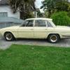
Look what the postie dropped off today! Going straight to the machinists. I love NOS.
1 point
-
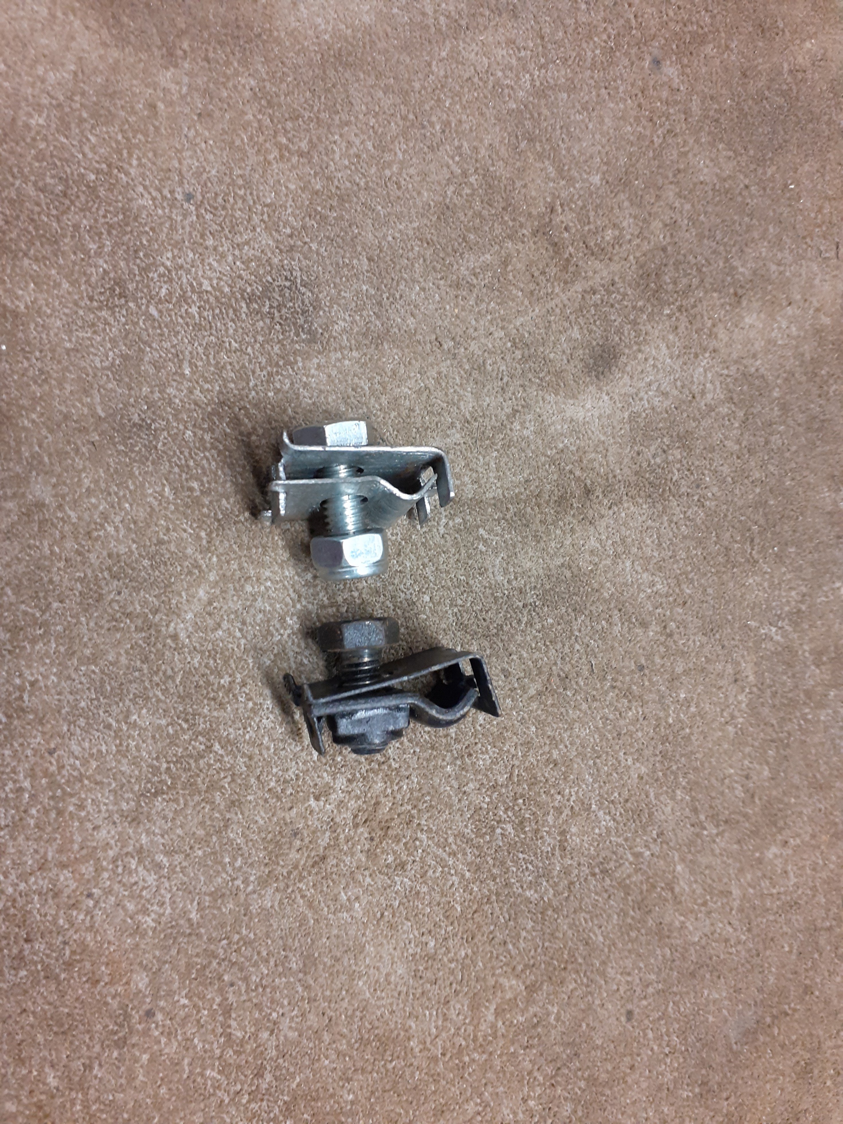
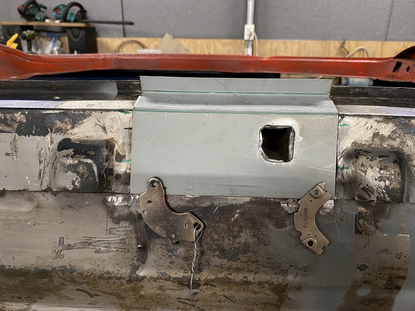
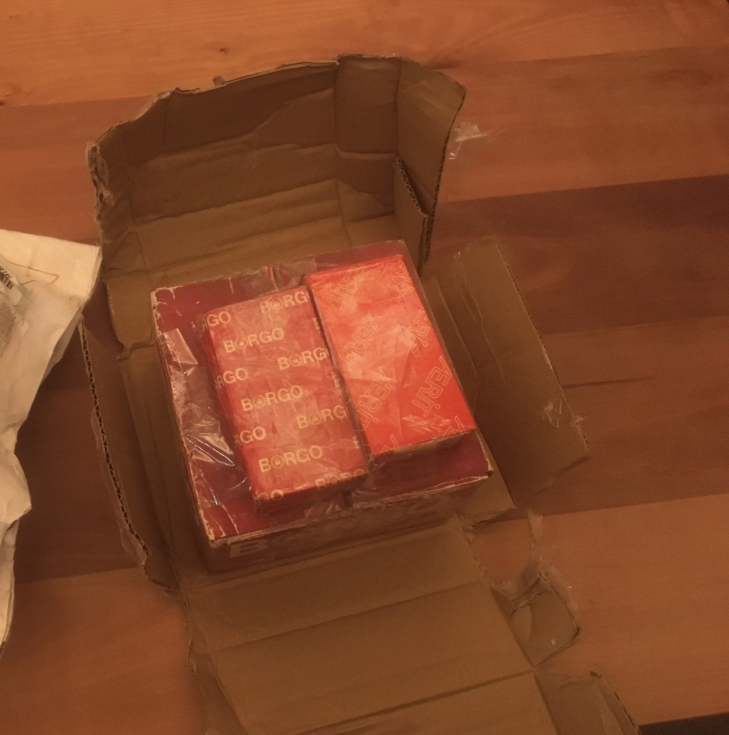
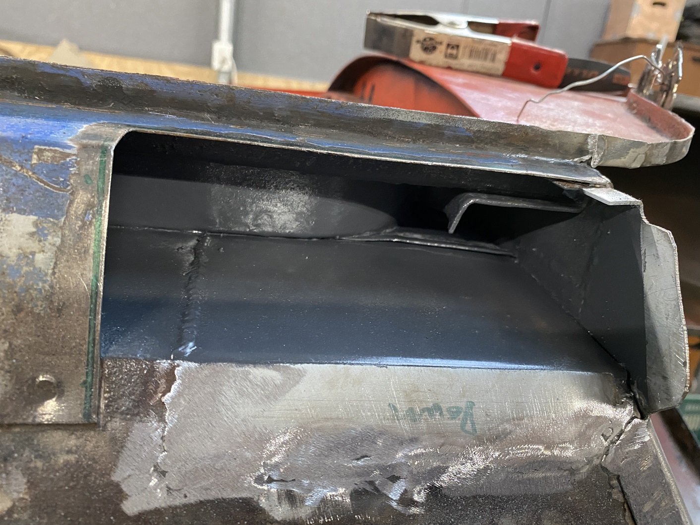
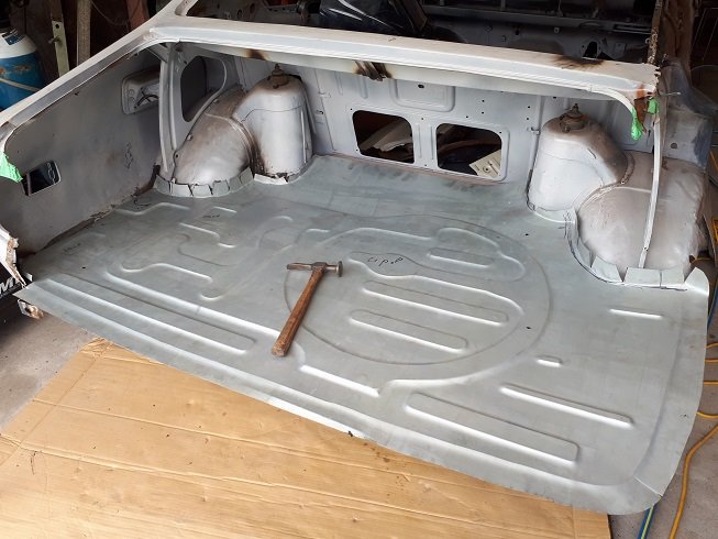
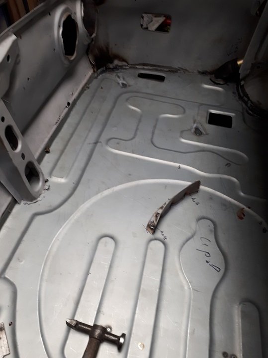
Filled in some more hole. Threw some paint at it. Made the closing panel. But still need to make the vent thingy.... it would be so easy to have no vent. But I can't do that.... Instead of making the vent thing, I procrastinated by filling in this hole. And removing this bracket that was squashed, so I could flatten the floor a bit and reshape the bracket. Apparently these are not actually jacking points, they are used in the factory to hold the floor assembly to a pallet thing as it moves along the production line.
1 point
-
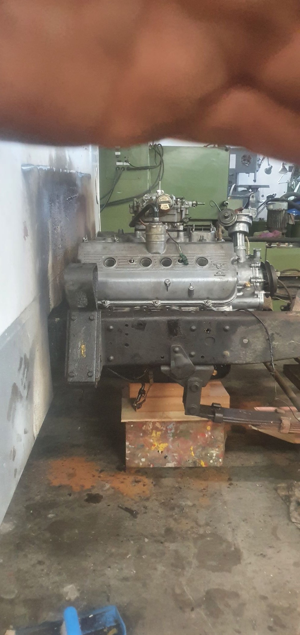
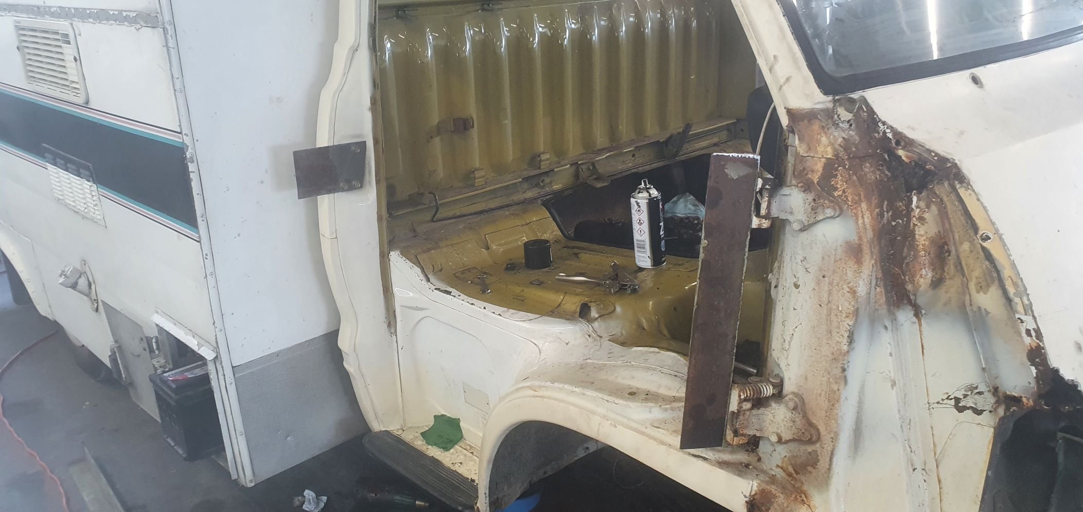
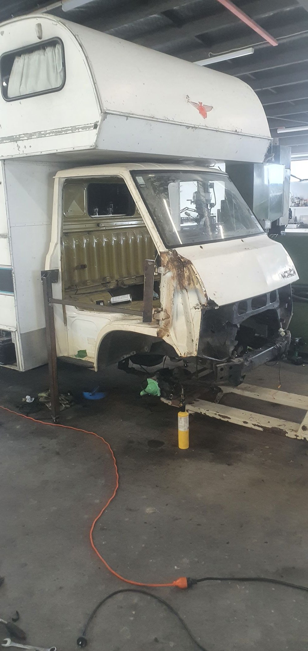
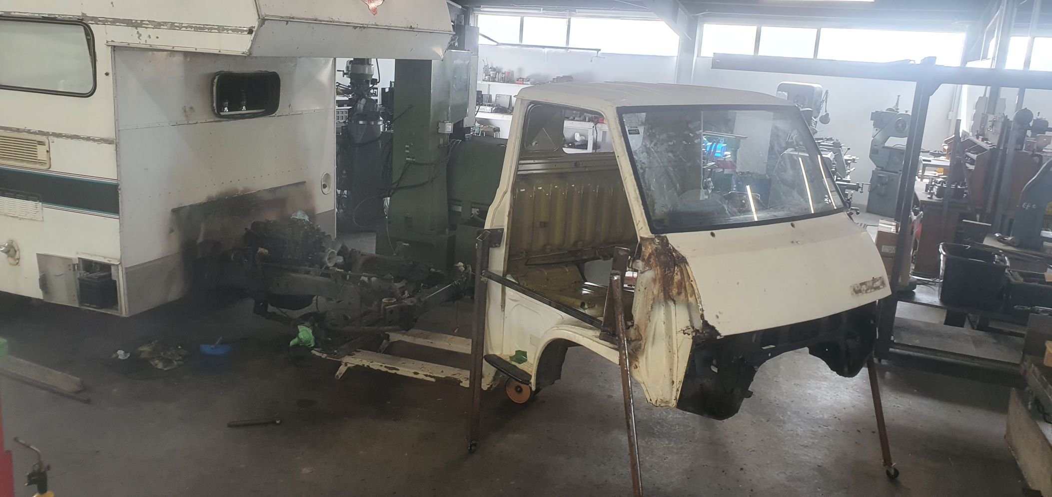
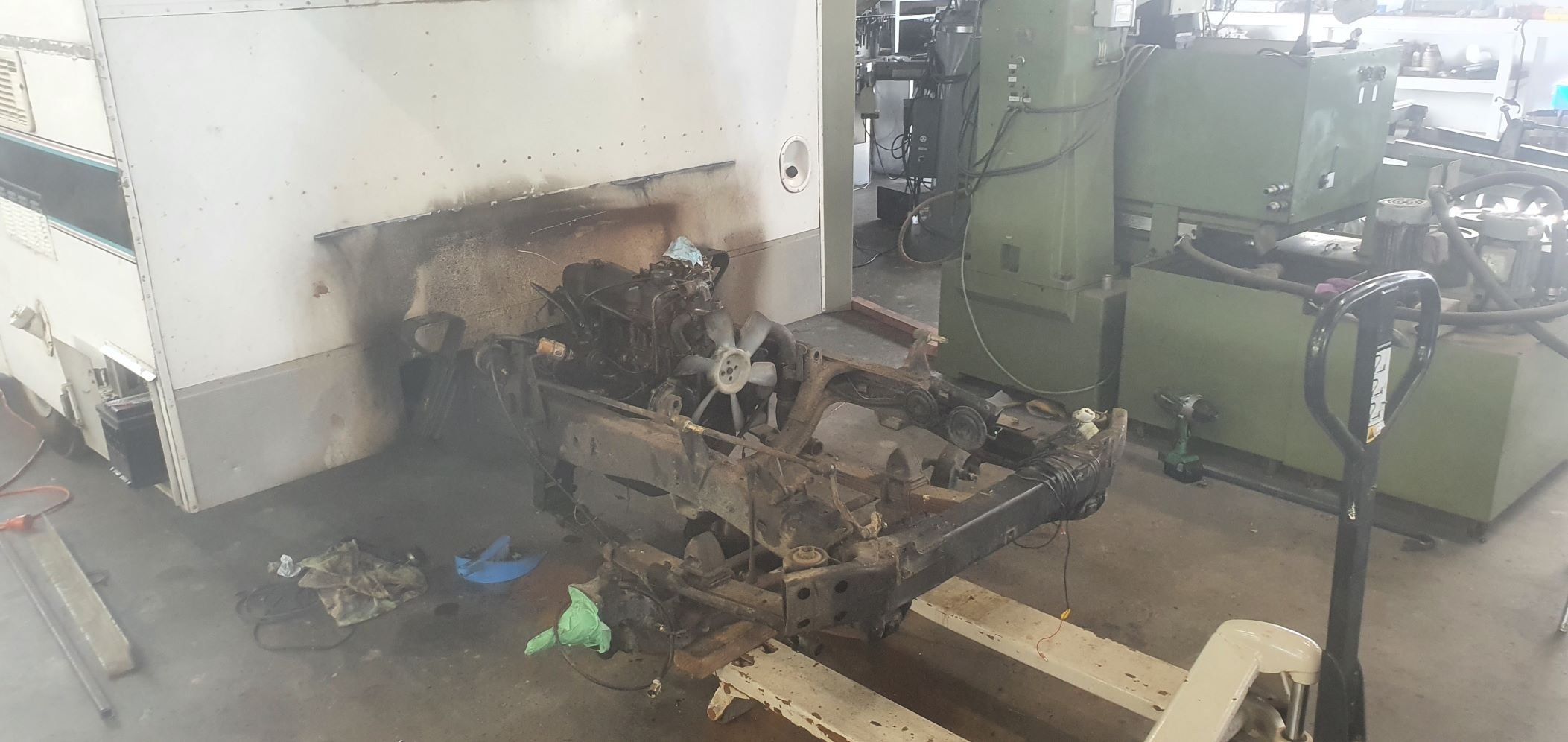
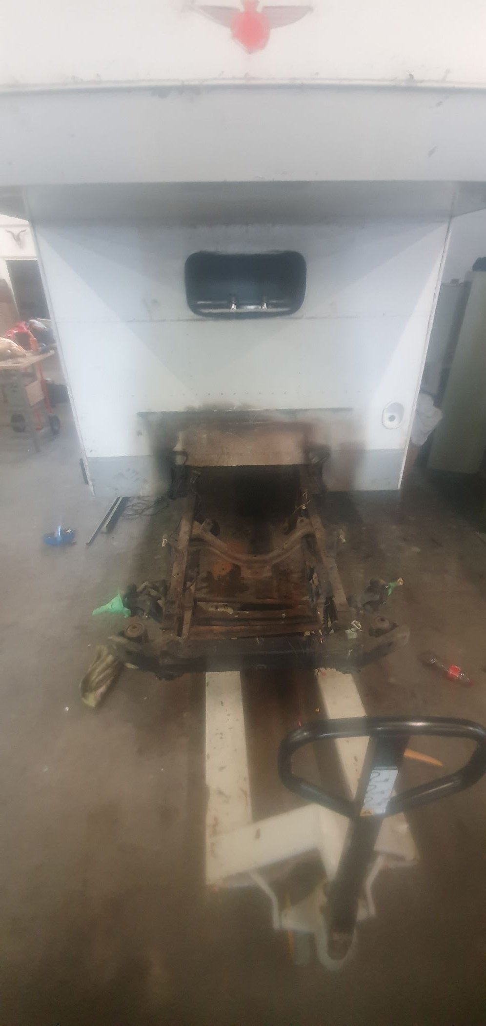
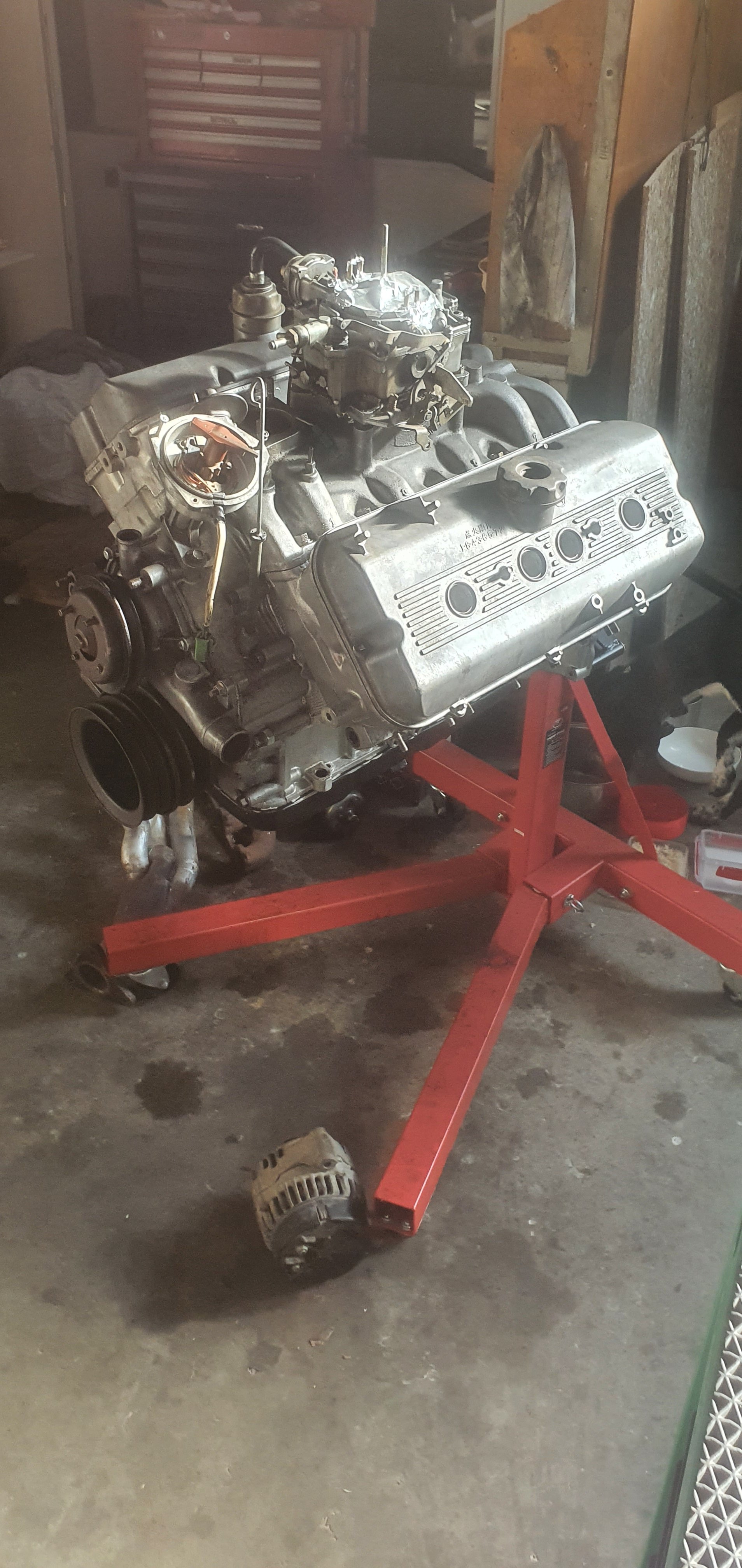
Big day of mahi today. Started by making two frames which mounted on each of the door hinges/door catches, castors on the bottome so I could slide the cab off without lifting the camper body. Worked out pretty well, cab came off relatively easily except for the dreaded last two bolts.. oh and some minor inner guard grinder removal work Engine was revealed, lots of this shit has to go as going from manual to auto box really simplifies things. So, dat what I did... At the very worst at least I still have a caravan.. am actually now thinking Ill put coupling mounted on the front chassis xmember for towing it around.. Am now gagging to slot that V8 between the rails. It measures up pretty good now that you can see what you have to work with. There may need to be a little relief on the camper body itself for the weird bulge on the top of the bellhousing, but no biggy. Apologies for grainy pic my camera is smashed.
1 point
-
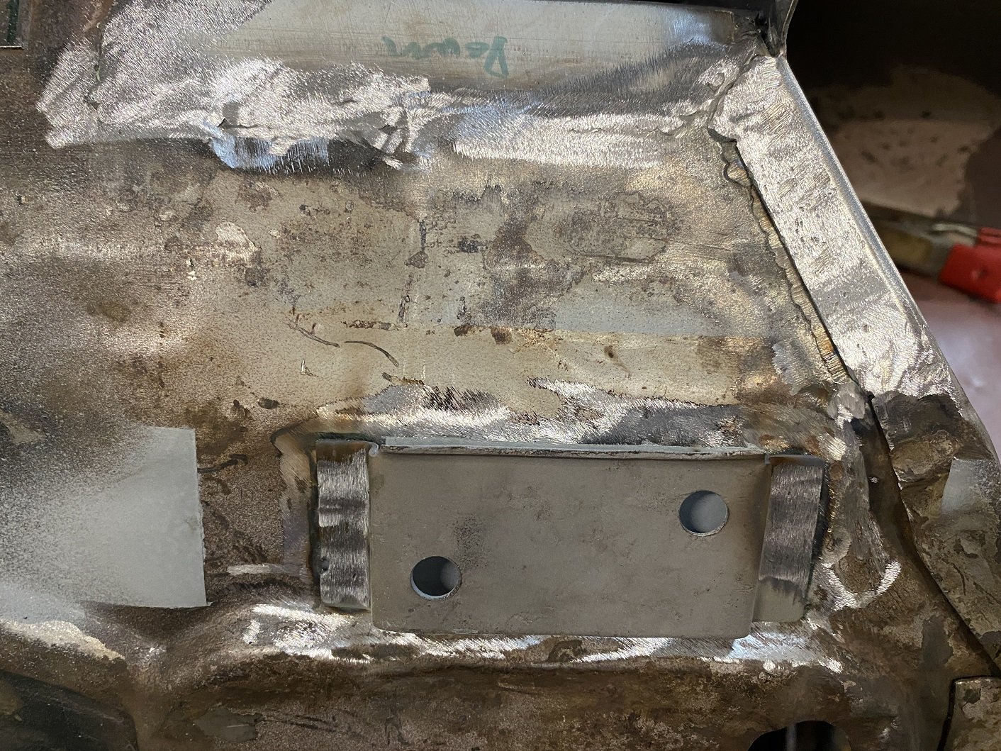
Filling in the hole I made.
1 point
-
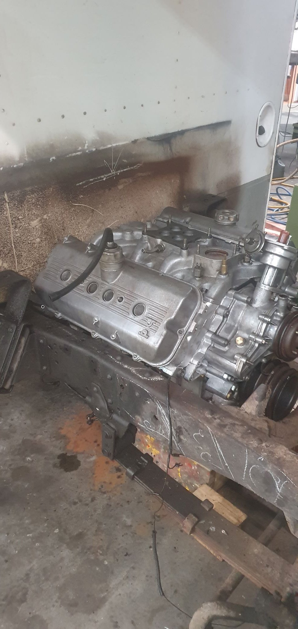
Engines been cleaned up pretty good awaiting slotting between the rails. Still have to make alternator bracket, and the seals under the rocker covers which seal around the spark plug tubes are toast so machining new ones there too.. Will probably make a set of log-style headers. Next weeks job is to get some flanges cut. Tomorrows Job is cab off and old engine out..
1 point
-
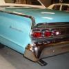
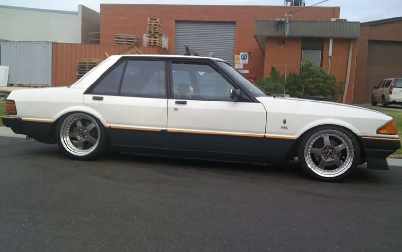
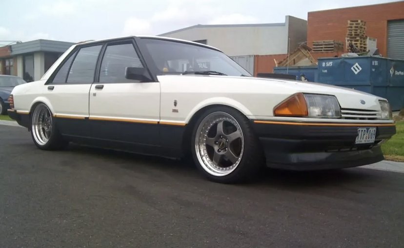
I’ve been spitballing factory paint options for a while now and love the factory metallic blue look….however I think I like the 2-tone look a bit better. Charcoal and Snow White as seen on some XE ESP’s from the factory. Even the OG 18” yea bud Simmons looks killer on this Pretty sure this colour way with the Spare tan interior will look pretty smart and the fact my car is a low spec GL Falcon, I don’t mind doing a tasteful tribute to the mighty XE. They even have the repro moulding kit too which is rad! Hopefully I’m picking the XE up from its barn this Saturday and bringing it up to the 09 for a decent tidy up and clean when we move to our new house. I should be able to crack into this build a bit more soon so watch this space
1 point
-
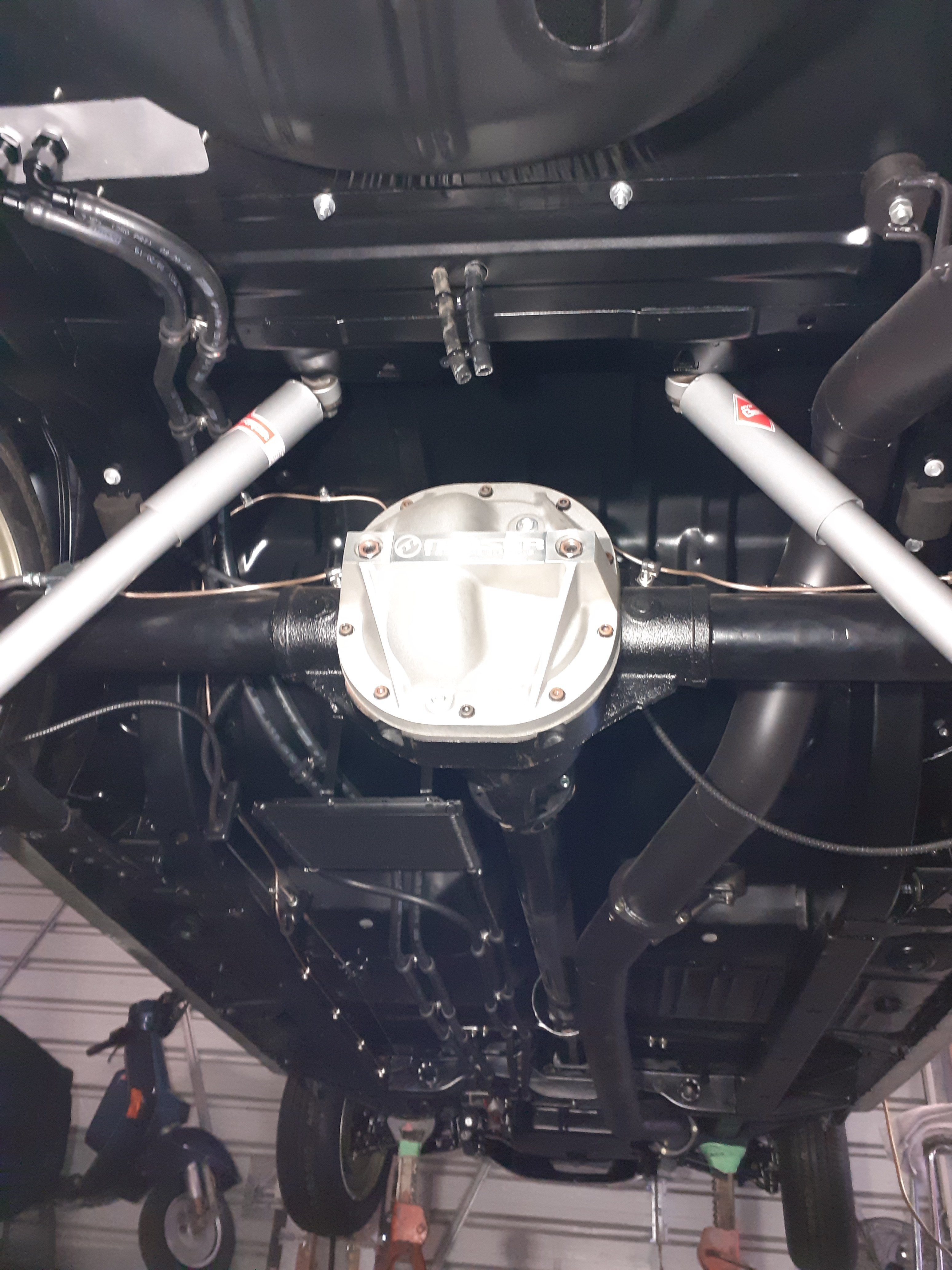
Trans cooler mounted, shifter cable set up. Underneath looks pretty busy now but there's no other way of getting everything to work so meh. Ordered some sound deadner stuff for the floor before carpet goes in
1 point
-
Not to poo poo your A+ barrying +1 safety glasses up to +2.5 I think https://nzsafetyblackwoods.co.nz/en/bolle-bifocal-iri-s-diopter-1-0-safety-glasses-each--412253 +2.5 https://nzsafetyblackwoods.co.nz/en/bolle-bifocal-iri-s-diopter-2-5-safety-glasses-each--4122561 point
-
Motor and box in for good now, plus a number of other parts, including the new HPCd extractors
1 point
-
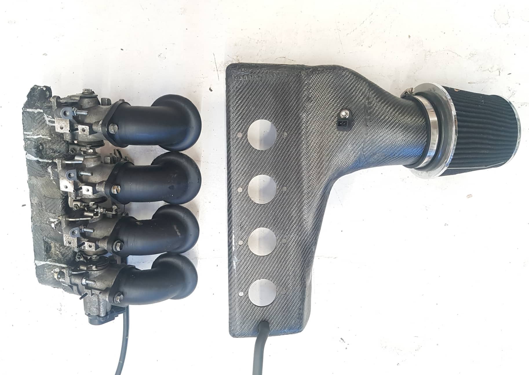
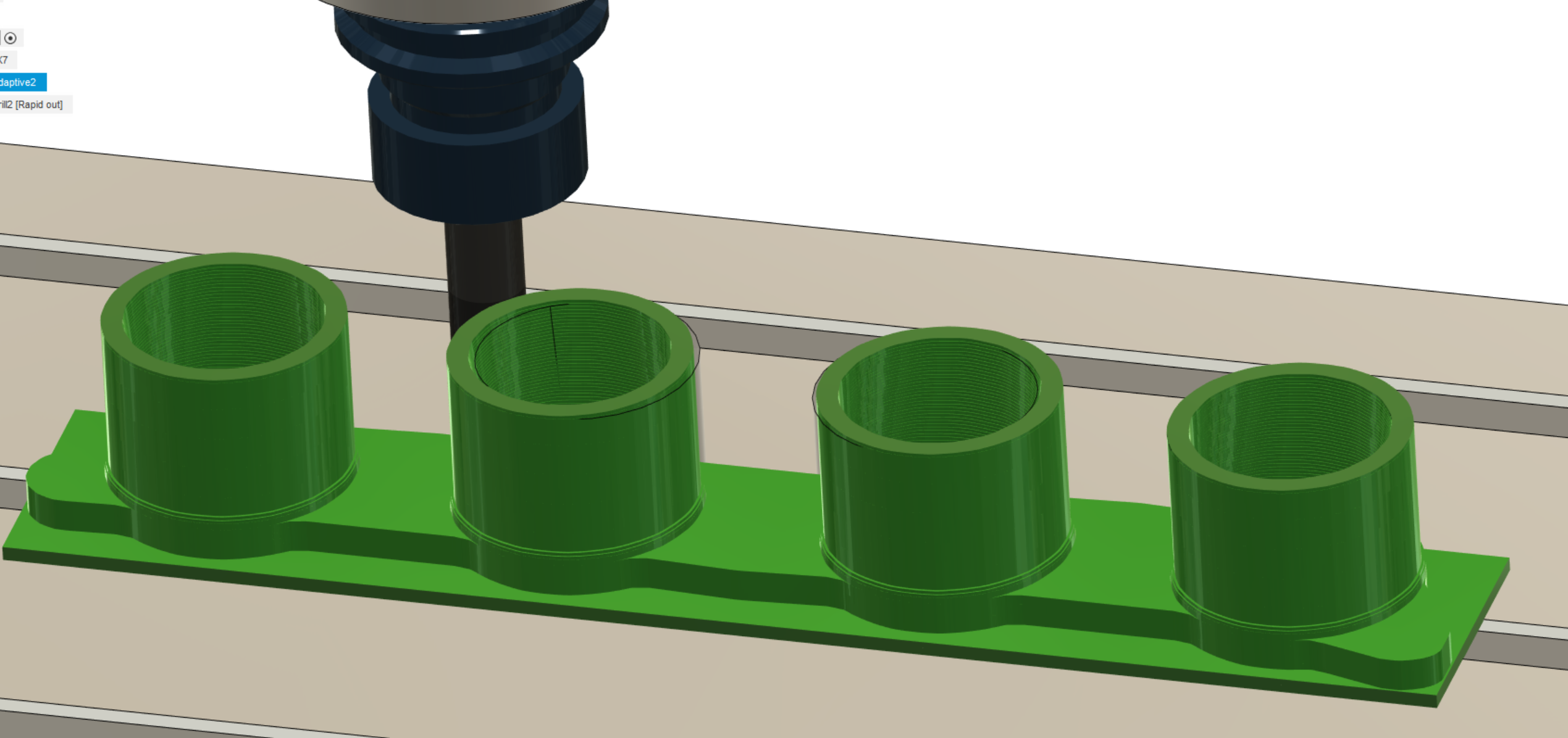
Yeah the way the cams work in the standard motor, it's more like a 750cc motor with an extra long stroke on the expansion side. I test drove an Aqua that my partner was considering getting, it's so absolutely hilariously different to this. This weekend on Sunday is an event at TECT park in Tauranga-ish area. This looks like heeeaapppsss of fun, its basically a super bumpy gravel track that's pretty wild But my car might be a bit low and come home sans bumpers. If I go to this, I'll keep the aqua manifold on as I've got more confidence in its dust filtration abilities. Alternatively if the red light situation changes, it might be Night Speed Drag Wars by this Friday. In which case the ITB stuff can go back on, no sign of the BMW bits yet. Otherwise I'm gonna hang these up on the wall until the other bits arrive. Pretty stoked with how this stuff turned out, and some of the milestones achieved with it. I've been trying to get a head start on the situation with throttle spacing on the BMW setup. I managed to find a scanned image of the engine's head gasket, then scale some measurements to try find bore spacing. Then I'm assuming the intake ports are central to the bores on each. 1NZ is 83mm bore spacing, and it looks like the S1000RR motor is going to be in the vicinity of 83-85mm centers based on scaling. So fingers crossed that this is the case, as it'll make it super easy to machine a manifold. Assuming an 85mm spacing it ends up like this, so slightly narrower would be just fine. Also if I end up CNC machining a manifold, I can keep the design a lot simpler because the material is so much stronger. I will probably add some degree of bridging between cylinders and add a few fillets once I know the tool sizes we'll have. But I can just focus on trying to make the whole thing machinable from one fixture position on the bed. (hopefully) Version 1.0 probably through to version 6.0 of this will likely be 3d printed anyway I guess. The tool path simulation stuff in Fusion 360 is pretty cool
1 point
-
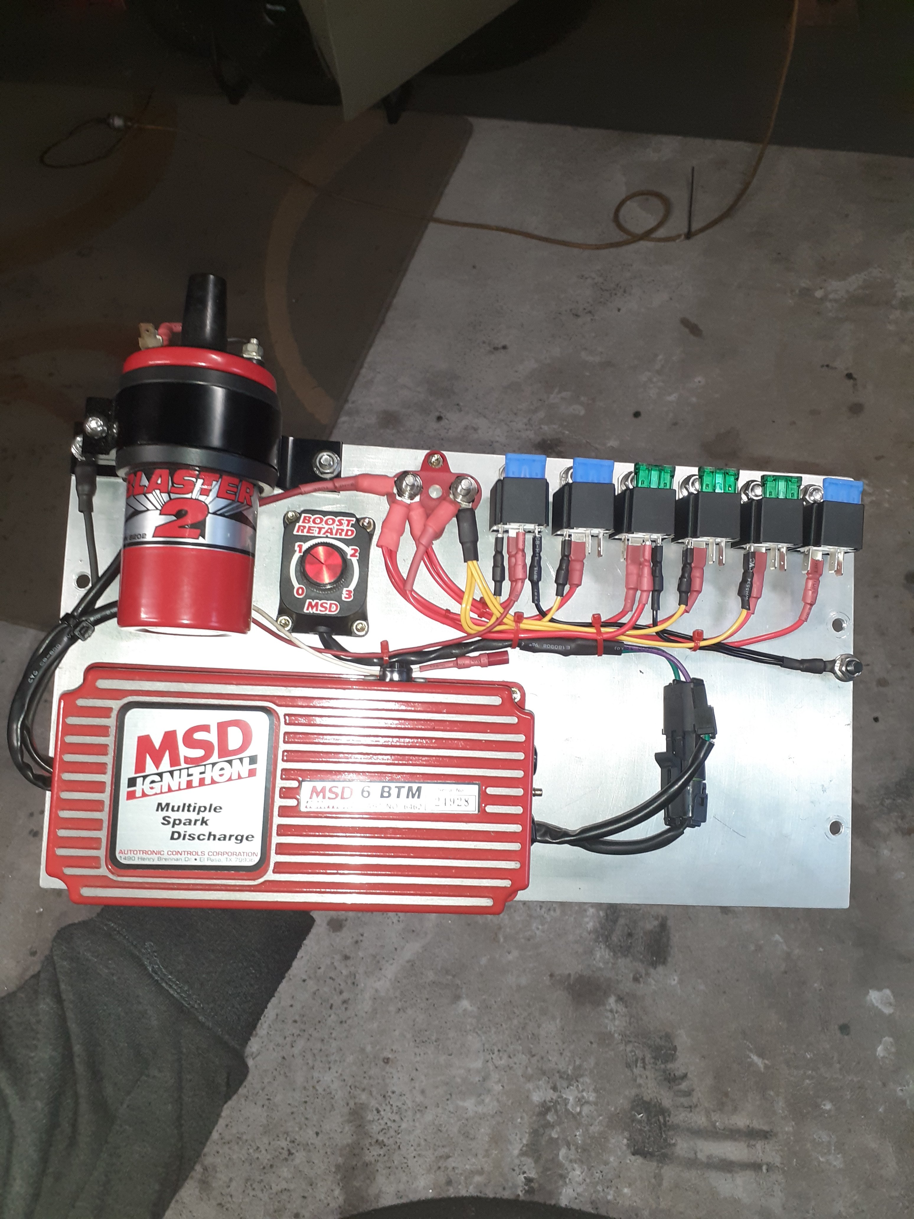
Relays done and half the wiring to them sorted
1 point
-
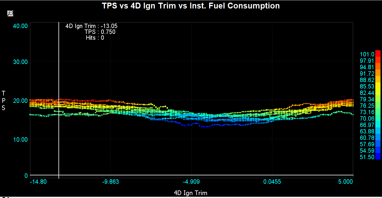
Alright so I got cruise control working, hooray. Firstly without the brake pedal wired up, which was not fun so quickly added that too. So it turns off if you tap the brake. So the plan from here is that I can turn on the cruise control and have the car try to hold a constant speed (say 100kph) Then I am using a timer that slowly sweeps an ignition trim from subtracting 15 degrees of timing, to zero, to adding 5 (didnt want to make it knock, so start out on conservative side) So if the motor is losing power because of the change in ignition timing, the cruise control has to open the throttle further. And vice versa. So driving along the motorway with this looping over and over and over, it starts to build up a trend of what ignition timing needs the least amount of throttle to hold speed (which of course means makes most power) So the dip in the graph is the ignition timing with best fuel economy. Surprisingly, it looks like it wants to pull about 4.5 degrees timing out from existing number (about 22 deg). I guess high compression means everything burns fast, even when the load is low. Because now my low load numbers are going to be a few degrees different from full throttle. I figured my existing numbers would be conservative, if anything! So now I can just repeat this process about a billion times and start building up a nice ignition map for 91 octane at cruise conditions. Otherwise I can try get my canbus thingy working that automates this process that I made for the carina ages ago. But need to get my head around all the code again, gets complex pretty quickly. So that's a maybe.
1 point
-
We've come a long way eh. It used to be push rod engines with bike carbs, now it's Prius engines with drive-by-wire bike throttles.1 point
-
Well this is just fucking excellent.1 point
-
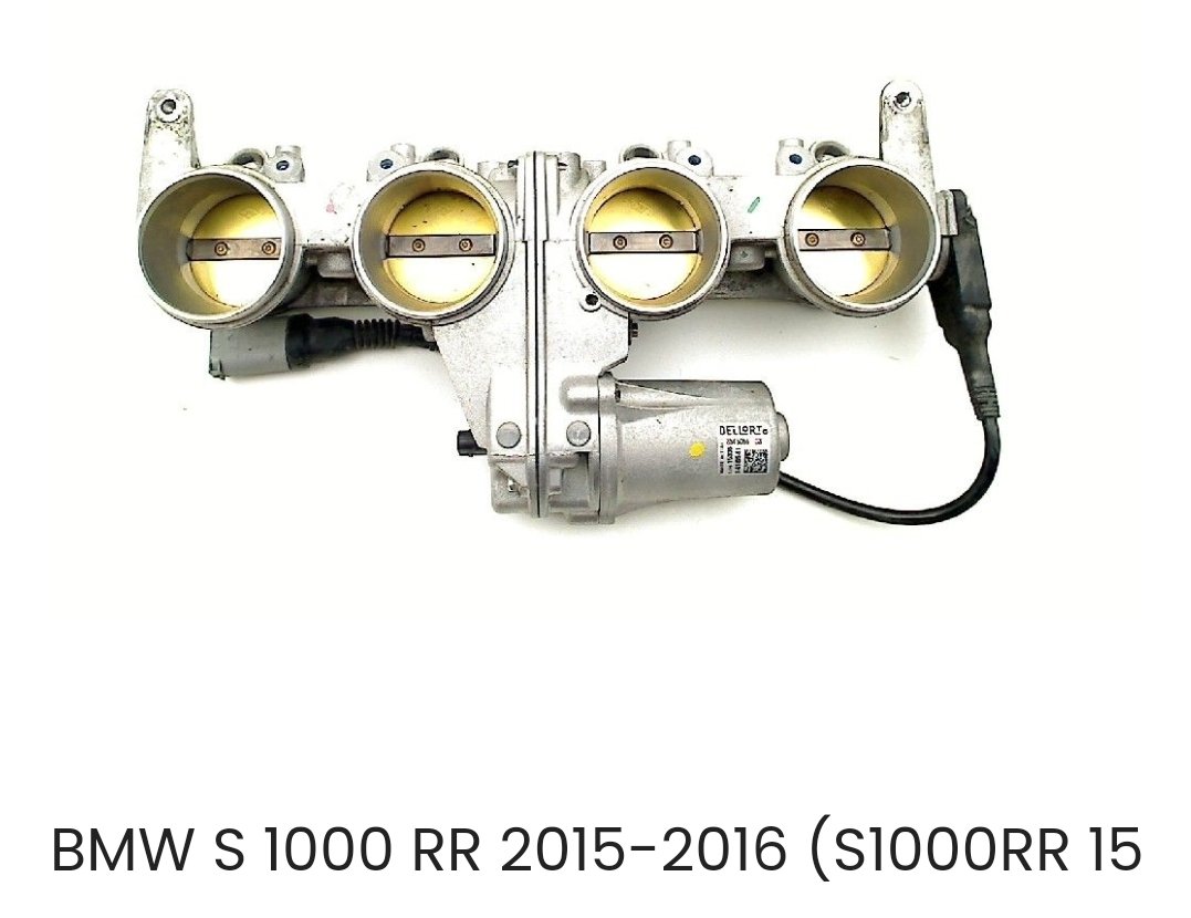
Internet says 45 litre tank. But I usually get around 35 litres in from a bit below empty. If theres still another 10 left after thst point then 800 will be doable. Also looking at itb options. Bmw s1000rr has 48mm throttles, built in e-throttle motor and super compact. Also extra injector bosses if needed/wanted. Looks like a sweet setup! Will keep looking for options but will keep these in mind for other projects.
1 point
-
At the moment I'm out of budget to get to any events for a while, or finish exhaust stuff. I almost managed to get a full tank of gas driving economically without hooning around (which ruins the economy incredibly quickly) But had some mates come over on the weekend who wanted a hoon around. So who am I to say no. But it looks like even with the throttles on, results in the ~5l per 100km would be achievable. High compression is win-win! So in the meantime seeing how gas is $3+ per litre. I figure I might try make a max economy effort and be able to run it on 91 octane. So I'm going to switch over to the completely garbage Aqua intake manifold, (with E-throttle!) and I've got an e-throttle pedal from an SCP13 vitz that bolts in. So this means I can have cruise control (hooray) and it makes it considerably easier to try optimize fuel economy by doing some repeat tests over the same stretch of road and comparing results. It turns out the Aqua has a small MAF than the other ones I've got here, and it wasnt included with th eengine. However one of the other standard sensors in the manifold that I thought was IAT is actually a MAP sensor. The factory motor would probably use some closed loop control methods by comparing MAF to MAP results to calculate how much EGR gas is present, and load the motor up as much as possible under steady state conditions. I'm not going to add EGR on it though, but I reckon this setup will be capable of some pretty good results. Surprisingly it looks like the quite tall airbox is actually going to fit in the engine bay okay. In other exciting news, possibly even equally as exciting as fuel economy chat. My Dad has ordered a 4 axis CNC machine, and I'm 100% keen to learn about it alongside. So in the longer term I'm going to try come up with a usable pattern for making an alloy quad throttle manifold, maybe onsell a few as well. However given the crazy price of even silvertop throttles these days, I'm wondering if it's more worthwhile looking for a commonish bike throttle setup? As I see some have factory e-throttle which would be awesome. As ideally I would have the throttle spacings closer together, and a smaller diameter throttle would mean I've got less of a gross transition to the port shape. I dont know much about bikes though, any suggestions on throttles to look for?
1 point
-
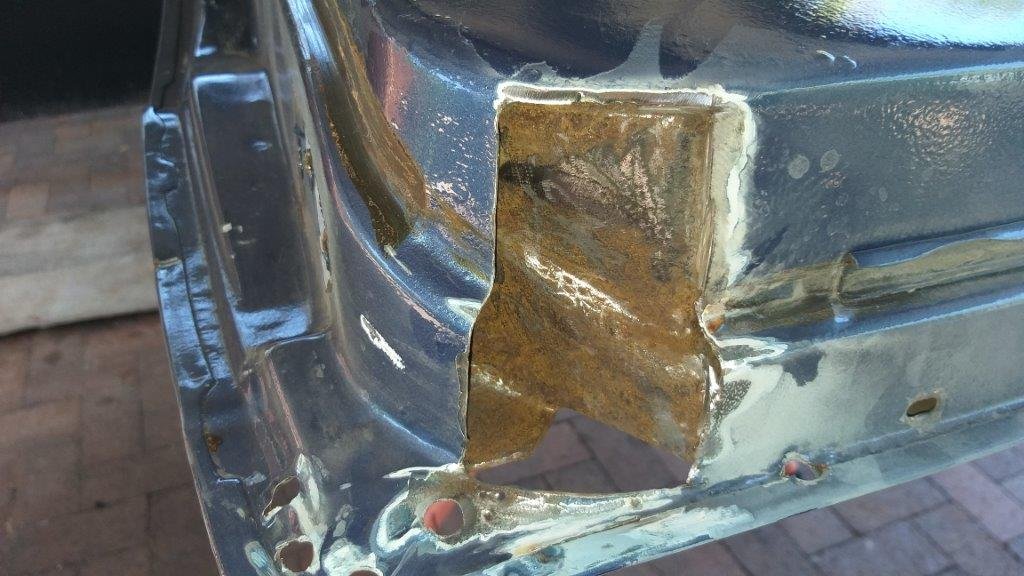
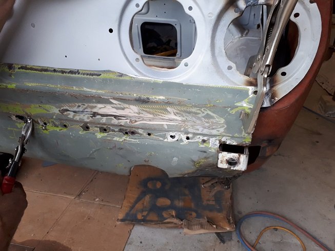
So the underside also looked pretty ugly. Again, I slapped it with a flapper disk expecting to find bog, but again no bog in sight. Cut out the nasty stuff and cleaned up as much of the inner as I could reach and applied a coat of rust converter. I'm relatively happy with the outcome thus far. I'll gut the driver's door tomorrow and then pull it off for some similar treatment. Thanks for looking.
1 point
-
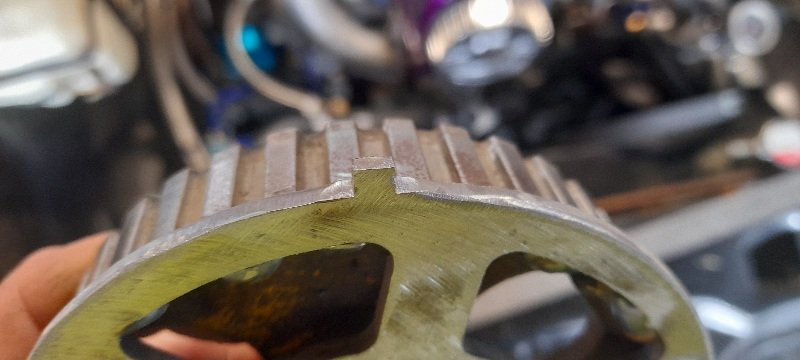
Gilmers are only ever acceptable when used on a 4k with a 3/4 race cam.1 point
-
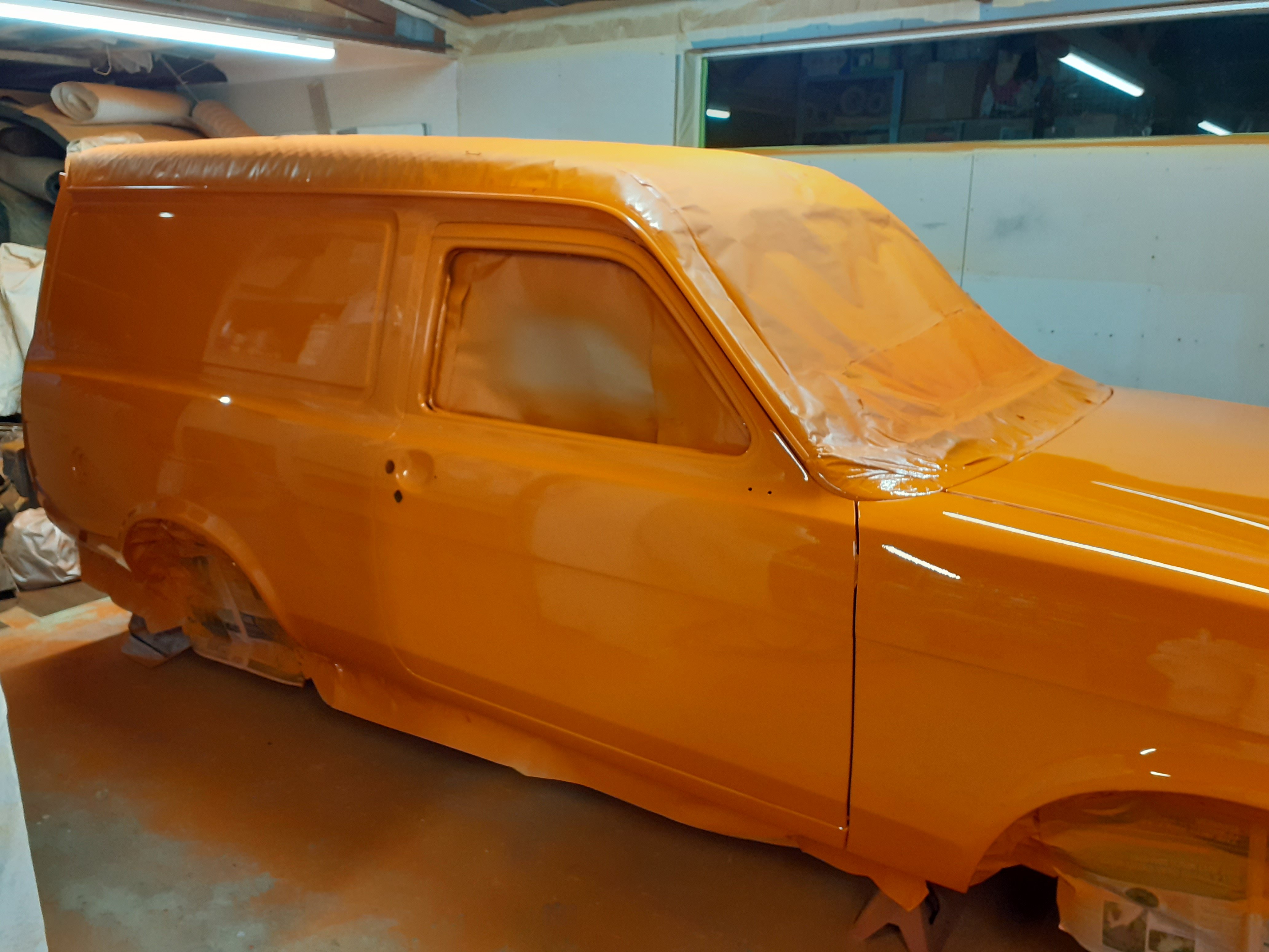
It's been a super long week but I finally painted the body. Its come up pretty damn straight but unfortunately I also have a few runs which will need sanding out. Absolutely stoked to get it to this stage but plenty more work to come.
1 point
-
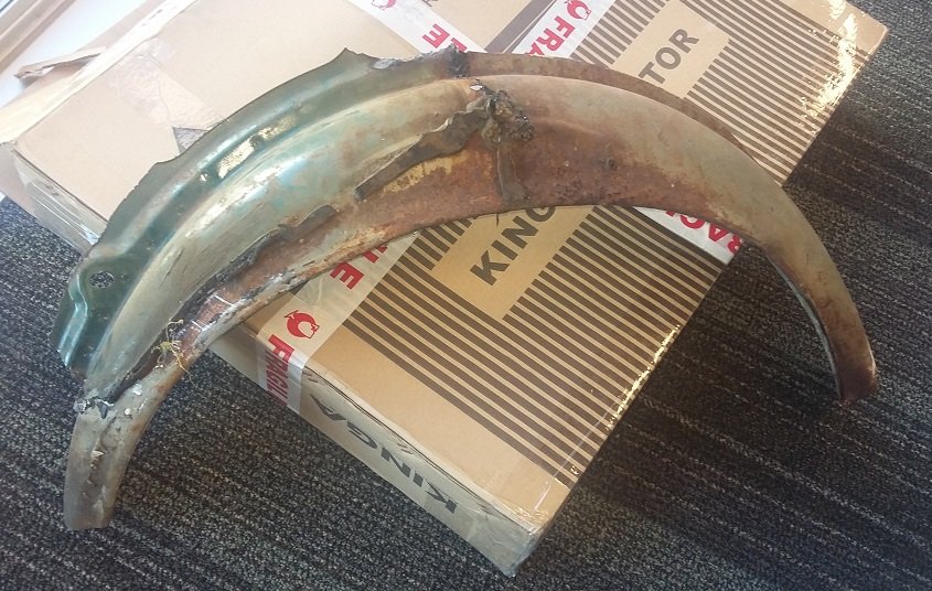
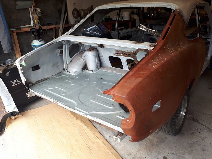
Inner arch was destroyed too, managed to source a 2nd hand item in good shape to fit to car. Then cleaned up inside, epoxied, and started on fitting up the rest of the panels. Hours of work in this but it came out ok, worst bit was the rear panel, I couldn't get a good rear panel and the lower half was rusty and damaged so I had to graft the lower section of a 616 one into it. Not the cleanest way of doing it, but its all we had to work with.
1 point


This leaderboard is set to Auckland/GMT+12:00