
Leaderboard


Popular Content
Showing content with the highest reputation on 05/07/21 in all areas
-
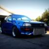
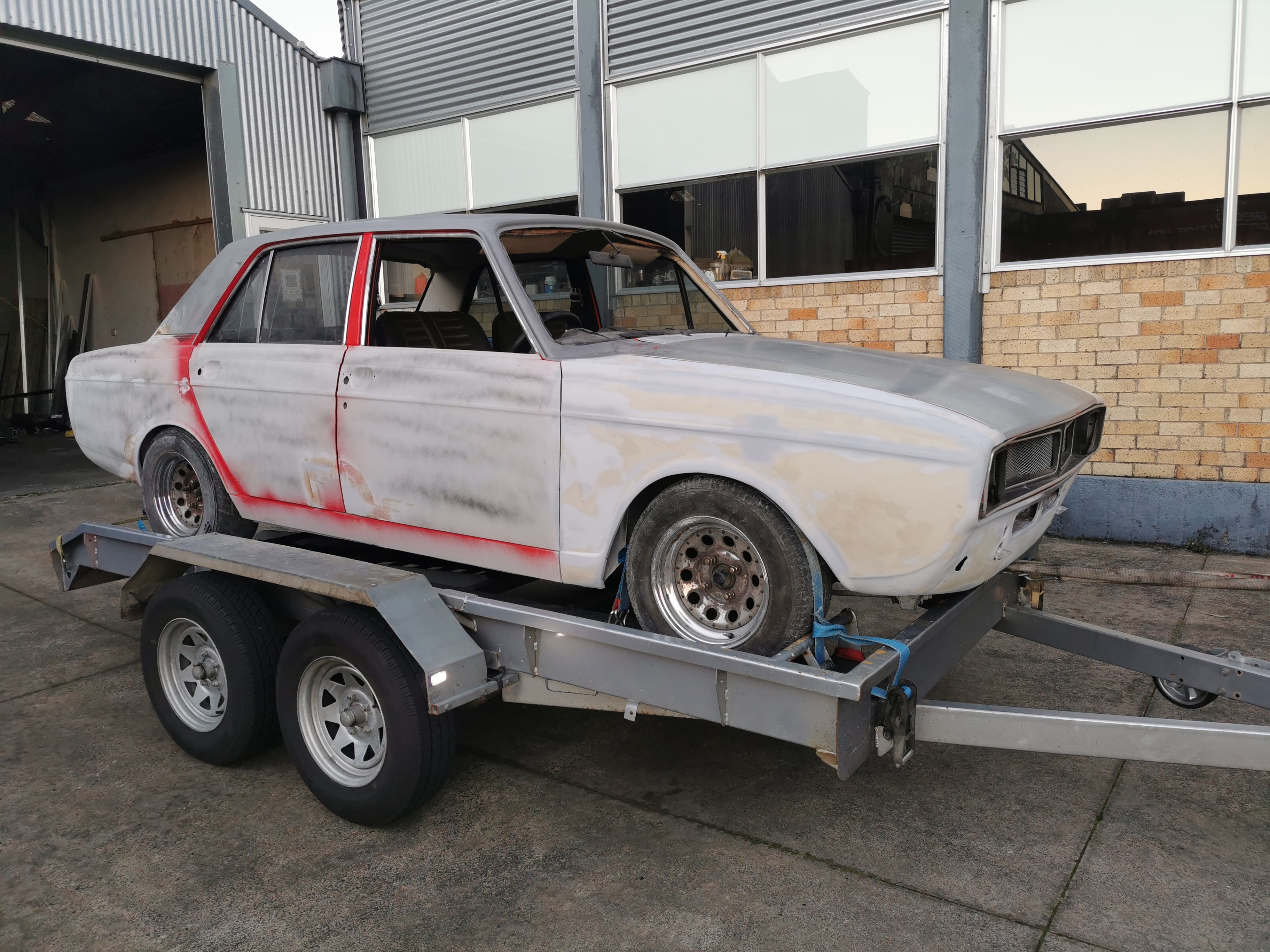
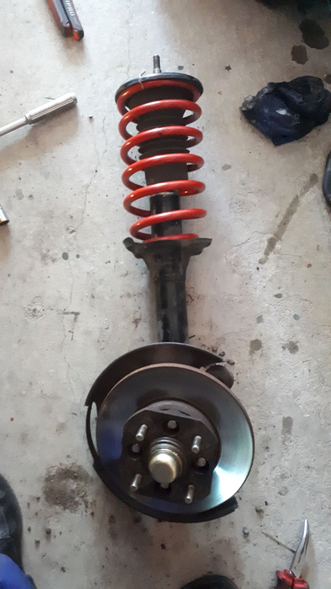
Oh yeah, I also added this turd to the fleet. I have no idea why, seemed like a good idea at the time. Will likely move it on if anyone is interested. Its a 1985 EP70, that someone has spent alot of time/effort/money into squeezing a silvertop 4age into. Its quite hilarious to drive and unlike my blue car it doesn't try to kill you. Comes with a Link g4+, coil overs, si interior, rear disc brakes, etc. If I keep it I'll turn it into a track hack. It needs some new panels and a few bits so if anyone knows of a reasonably tidy EP70 going or not then let me know - just needs to be tidy.11 points
-
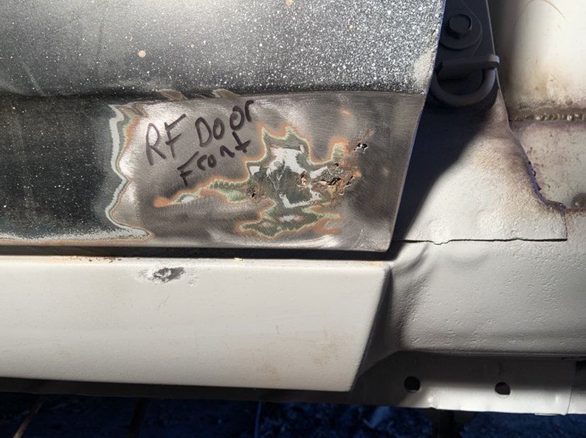
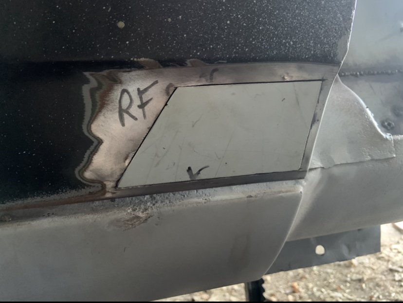
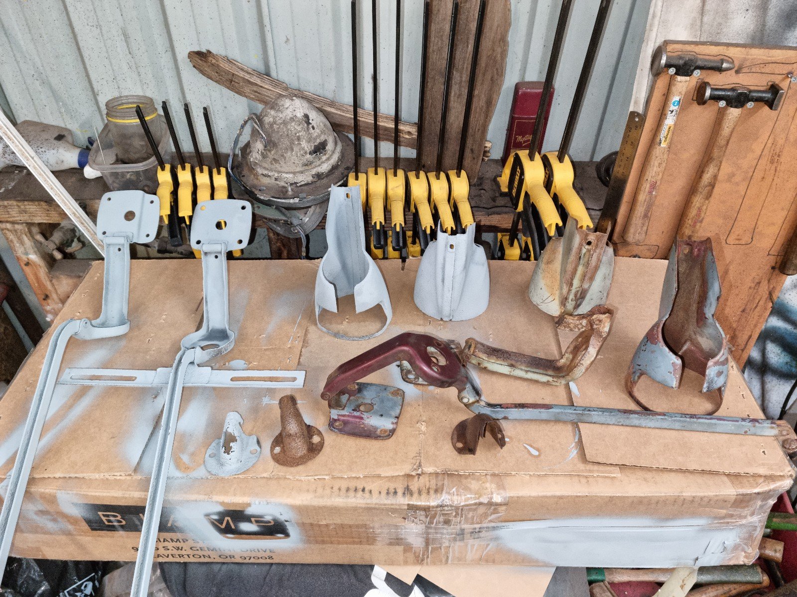
Well fertan was cool. I knocked the top off with a wire wheel on the drill. Applied the fertan. It’s just like deck stain, very loose and dark. It comes in a wee bottle with a spray/squirt gun like household cleaner. Has a nice spray and really hammers it on well. it’s not there to ask how your day was, it’s ready to fuck. If it isn’t a textured/pitted surface it wanted to run off. the instructions said let it sit for about an hour and dampen with water (yeah aye, water and rust) but since I applied it as it was getting dark I figured the next best thing was leave it on the drive for a nice even layer of moisture from the air. ah shit it was -2 when I got up, lol. Frost is even so it’s still a win. Once it dried it was kicking off a blue powder. I was instructed to leave it 24 hours before painting, 48 if it’s cold..but can wait 6 months before paint.. that’s a ballsy claim! The last step is to remove the purple dust with a damp rag and your done. Your left with a black part, rock on. I’ll etch prime with 2K this week weather permitting.7 points
-
6 points
-
Went gravel/adventure riding on the weekend. Man I need to go ride a bike more before cape. Also dropped Adv50 off for some work before cape / to get it ready for some pre cape missions. F I Z Z I N G6 points
-
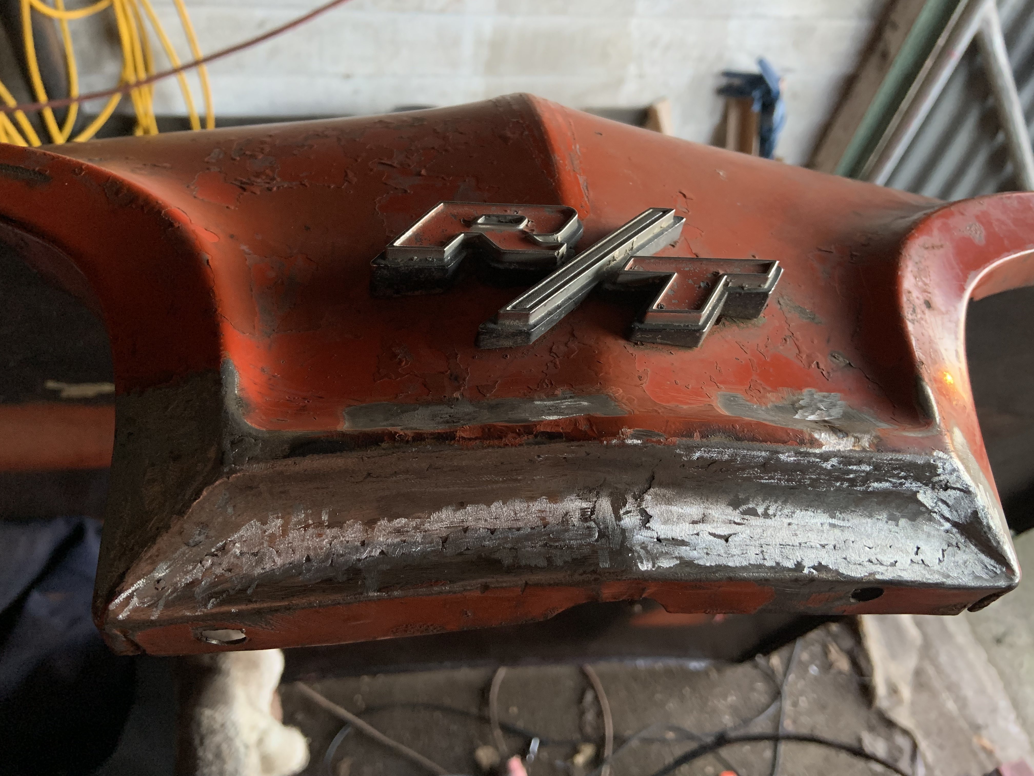
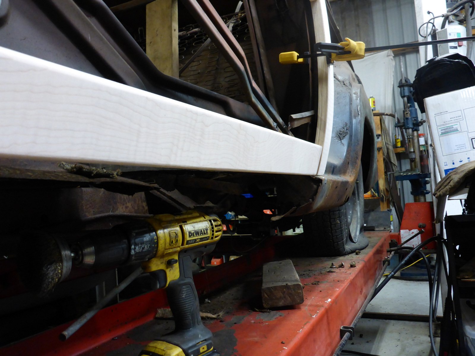
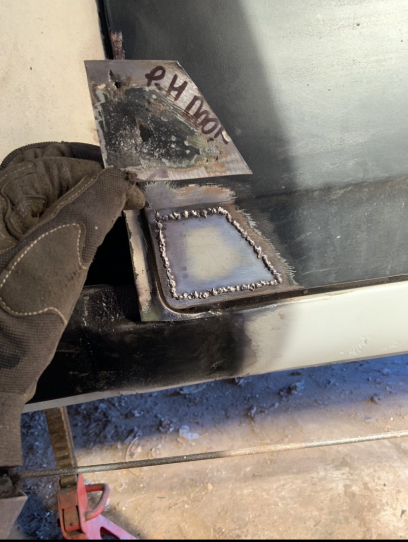
First of the inner sills done - had to go with functionality rather than a direct replica of the originals as there was just nothing left to use as a template.
 6 points
 -
i cleaned the things. then i put the motor back together. the cam gears have a slot in them for the dowel that is too big. the slot in the cam gear is 5.4 whilst the pin is 5mm. doesn't sound like much but its a good 5 degrees of play when you set up the cam timing. so to fix it i made some stepped dowels out of a 5.4mm drill bit. once id done that i re-dialed the cams to get them right. 2021-07-04_04-14-42 by sheepers, on Flickr 2021-07-04_04-14-49 by sheepers, on Flickr 2021-07-04_04-14-56 by sheepers, on Flickr 2021-07-04_04-15-02 by sheepers, on Flickr6 points
-
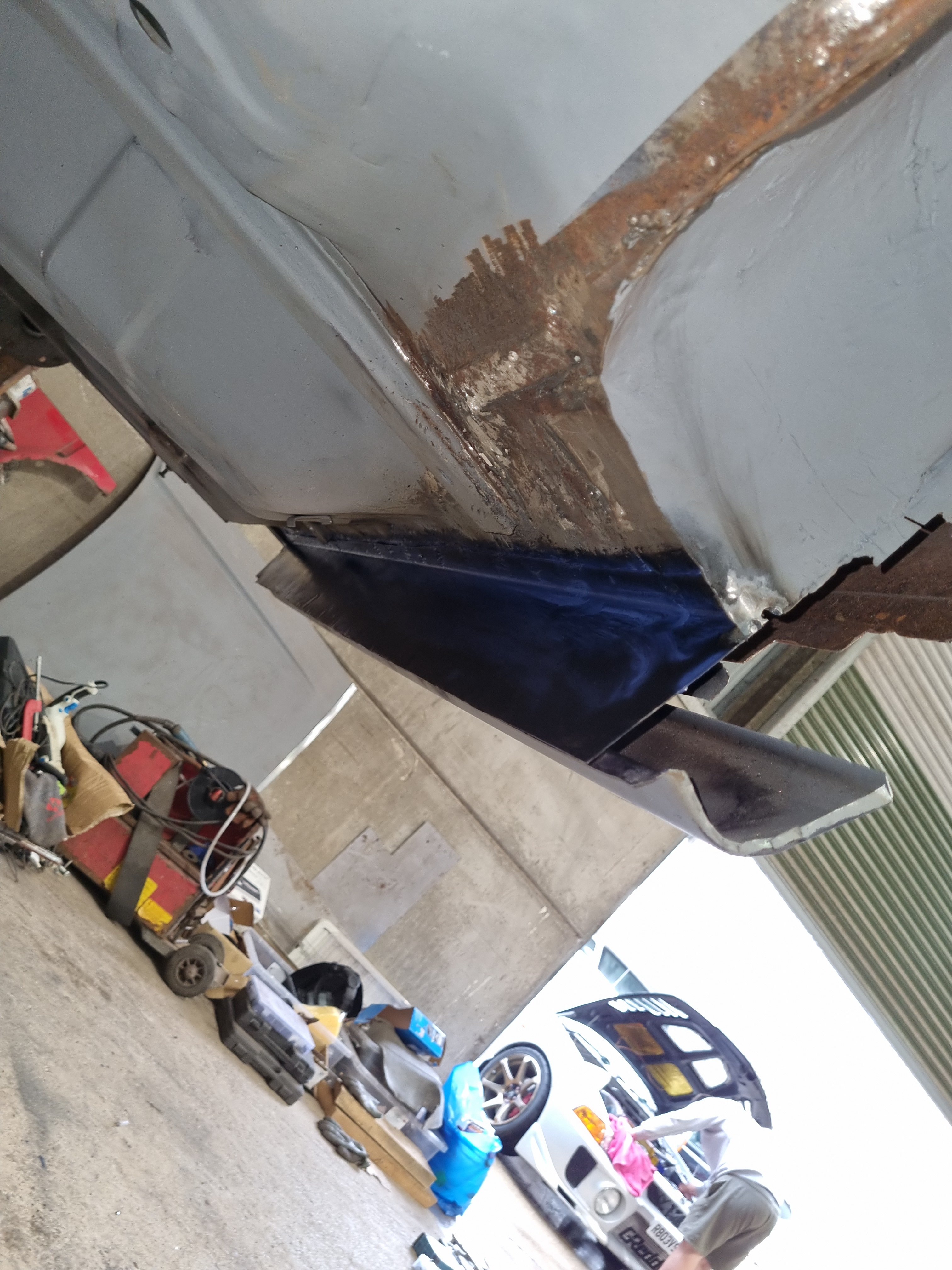
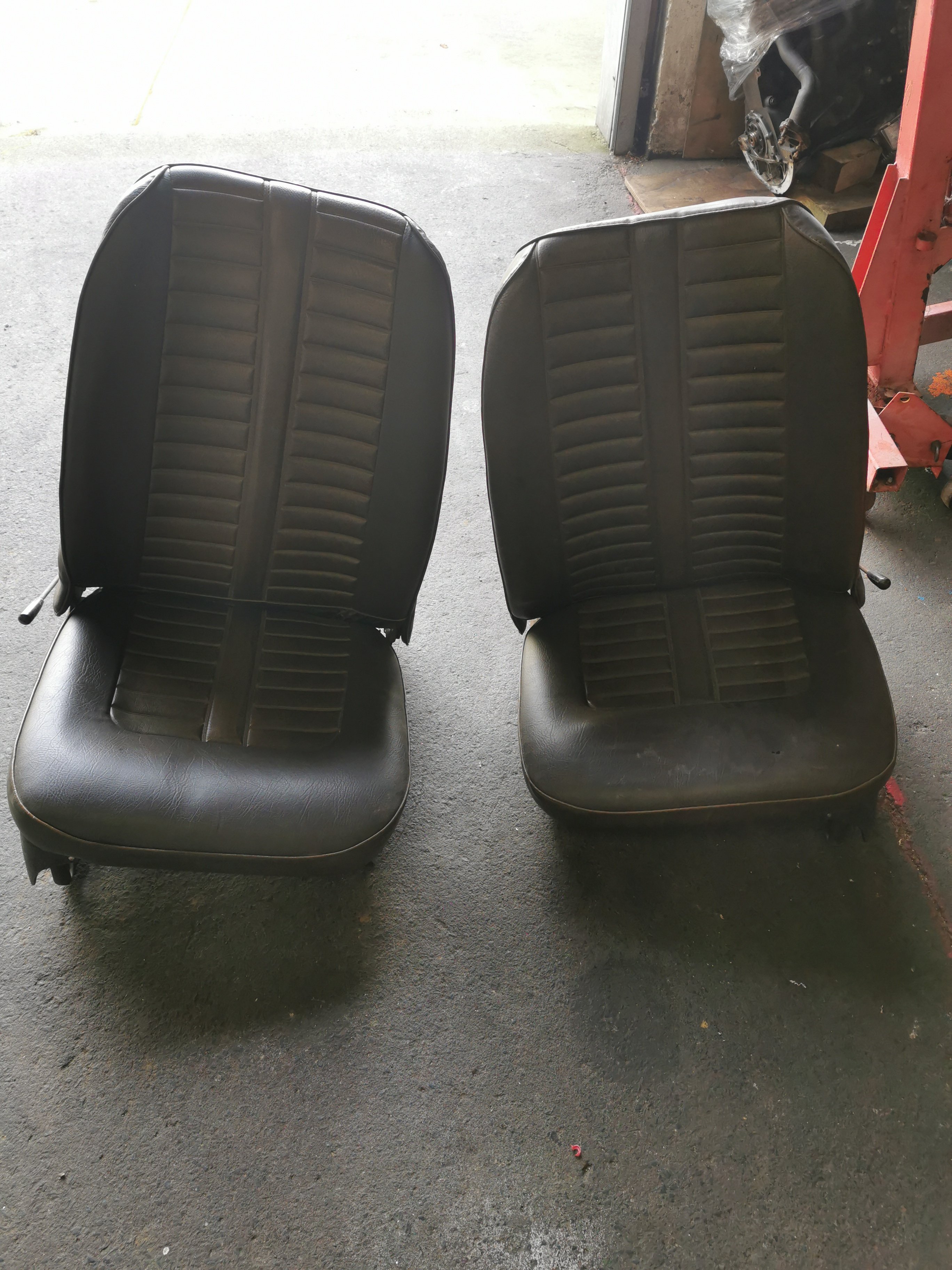
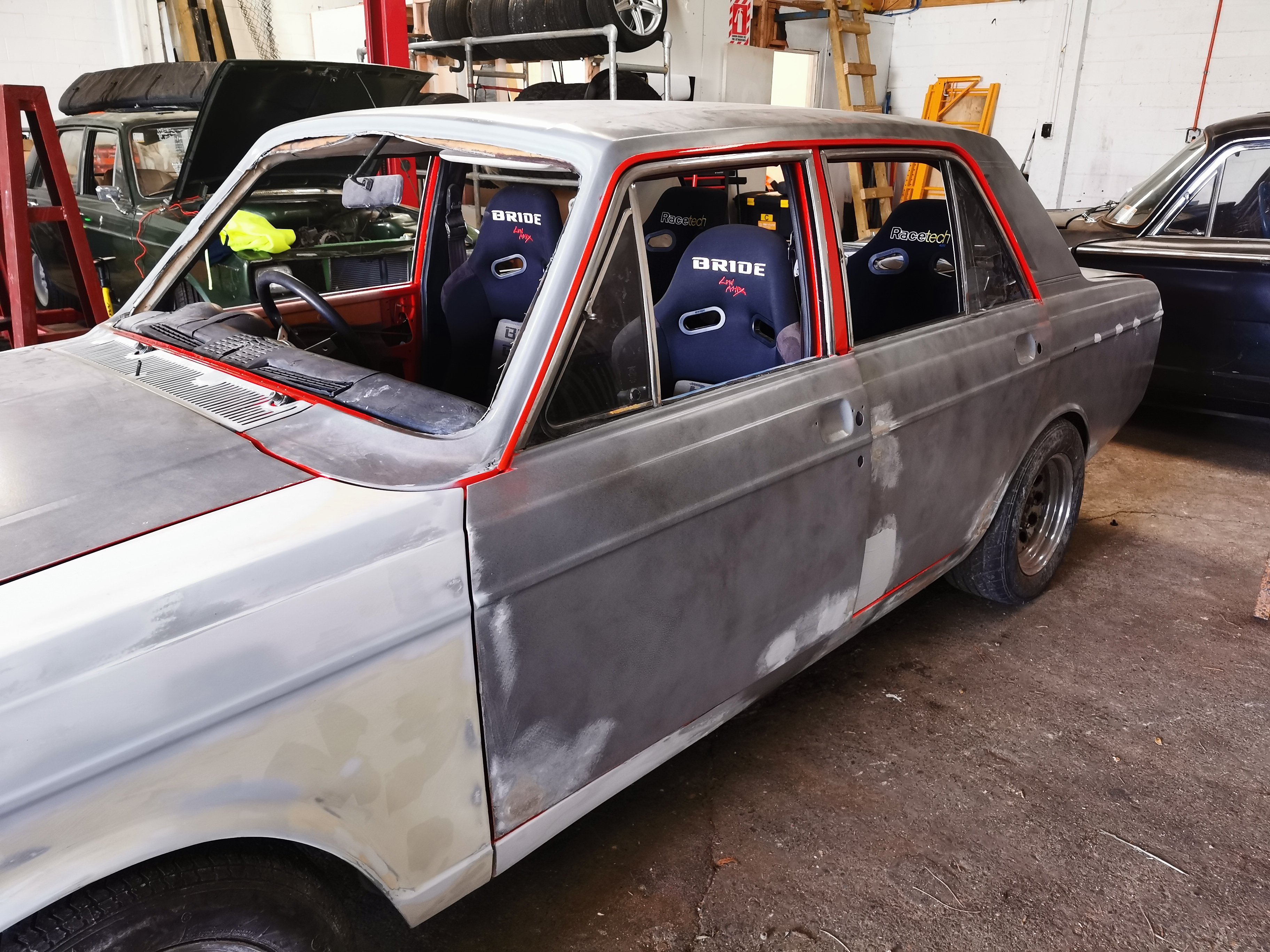
The seats are immaculate in this car.. Its a shame to sell them and put race seats in it.. But oh well, skids If anyone is after a full set of matching seats, front and rear, door cards, door tops and under dash pad, I'll flick them up on trademe. Reclining High back super seats. Pic for you @cletus
5 points
-
And for shits n gigs, quad race seats
4 points
-
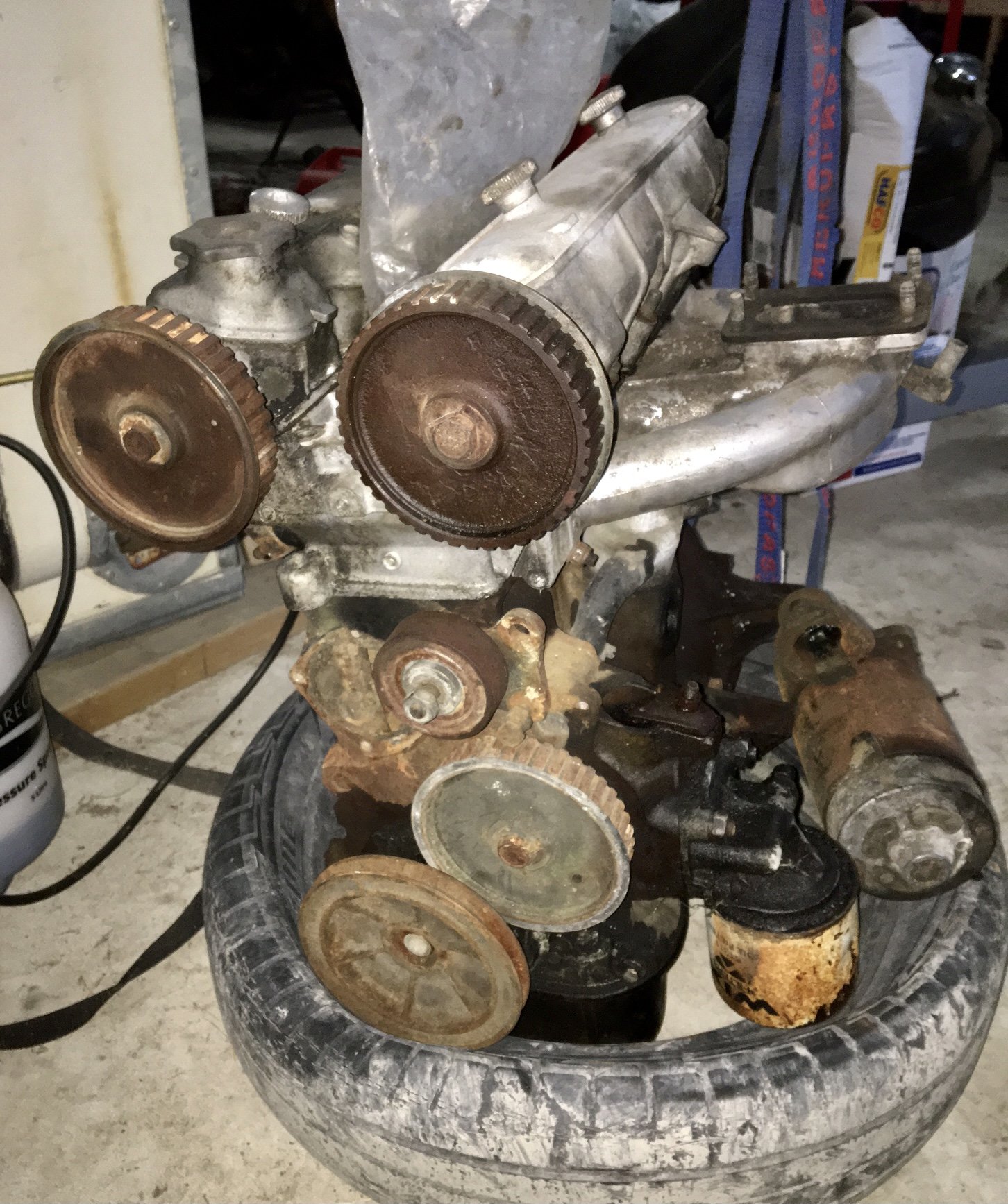
Snapped up this garage ornament. It’s a 1608cc 125 engine. Cams have rust on the lobes, so it’s definitely been sitting a while. Came with a carb (another Solex...) part of a starter motor, and a flywheel (which upon closer inspection has “Holden” cast into it) I’ll tuck it away and give it a good inspection in the future. The vendor alleges it “has good bores”. We shall see.
4 points
-
One difference the Pre-Facelift Carib has is that the taillights are big solid colour blocky things. I didn't really like them, so off they came. The original taillights always looked dated to me, which made the car look older than it is. The facelift model of both the Carib and Corolla wagon got a slight upgrade in the taillight department. Removing and replacing the lights is very easy on these, so I grabbed a pair of facelift lights from a Corolla wagon at Pick A Part and finally got around to replacing them today. With the tailgate open, it's just two screws to remove the lights. I guess this was designed to be easy as this is also how you change the bulbs. Remove the screws and then the light just pops out. There are two plastic pins on the opposite edge of the light, but these are often broken. In typical fashion, the lights on the Carib were loose, so that wouldn't be helping. With the light removed it uncovered a haven for grot A quick clean, and then it's just a case of swapping the bulb holders to the new lights, and slot the light into place. Rinse and repeat on the other side, give them a polish with some PlastX and that's the job done. They came up really well with a polish, and fit better than the old lights. Much better Nice and easy. I also gave the paint a quick going over with Bowden's Own, to get rid of more of the sunscreen on the paint. I was initially very sceptical about this, as it's well known how hard it is to remove sunscreen, but checking out reviews and Youtube videos of this stuff convinced me to give it a try. The difference to most other options is that this is oil-based and lifts the oil-based sunscreen out of the pores in the paint. Just over a month ago I gave it a quick test on a small spot that had some clear and obvious finger spots. Pour some on a microfibre, rub it into the paint and buff off. It's not rocket science. But sure enough, there was no trace left at all. And over a month later, there is still no trace. Despite what I've been told, I'm not an idiot, I know how bad sunscreen is for paint, but the results speak for themselves so far. If it lasts, awesome, if not, I'll try again. With that success in mind, I went around the rest of the car today and just spot polished where I could see sunscreen marks. The car looks a lot better now, with a more uniform shade of black. I still need to give it a clean and a proper machine polish and wax but that will come in time. The paint has a really nice flake, so should look great when polished.4 points
-
Meet hunter #2.. This is the replacement to the RS legacy I had.. This o e is going to receive a cage, race seats, the 12a bridgey and other goodies.. The motor in this is a stock twin carb motor, that will go into the green hunter.. That'll complete the og hunter and get it usable again.
4 points
-
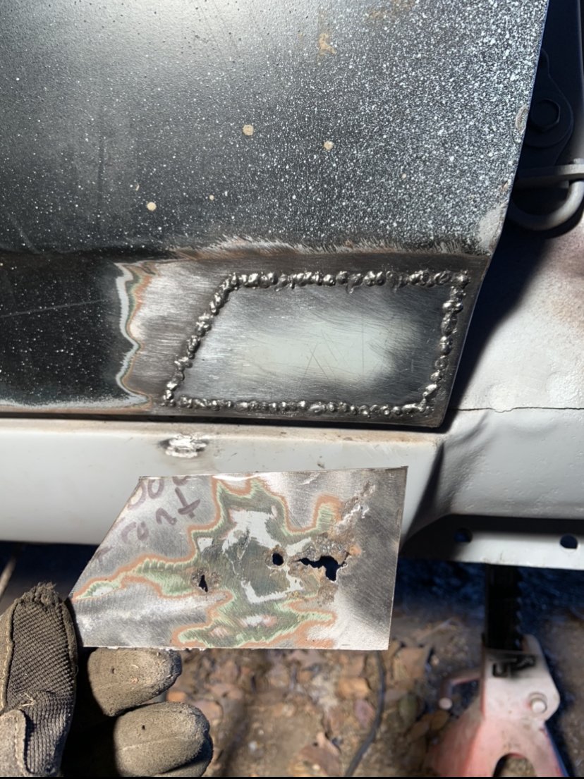
strip disc exposed the soft spots.. I need more dremel cutting wheels before attempting this one, as used last one the other day and forget to order during the day I lied, it wasn’t just the nose that rusted. for fox skates! Hate precision bonnet jobs. She’s had a wire wheel back and 2 coats of Brunox. I thought a round hole would be less likely to distort so used the step drill to open them up to fresh steel and zapped one weld at a time with a long cool down period in between. it worked, the important side is pretty flush and won’t need much aftercare. The brunox was a test, has a good name but haven’t used it before now. It’s all good, but doesn’t seem to go far and isn’t cheap. I’ve ordered some Fertan brand stuff to have a hoon on this time round, the inner of frame will be a great test for it. I got some front wheel bearings and 2L of 3M underbody Schutz for later on too. Stay tuned homos3 points
-
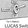
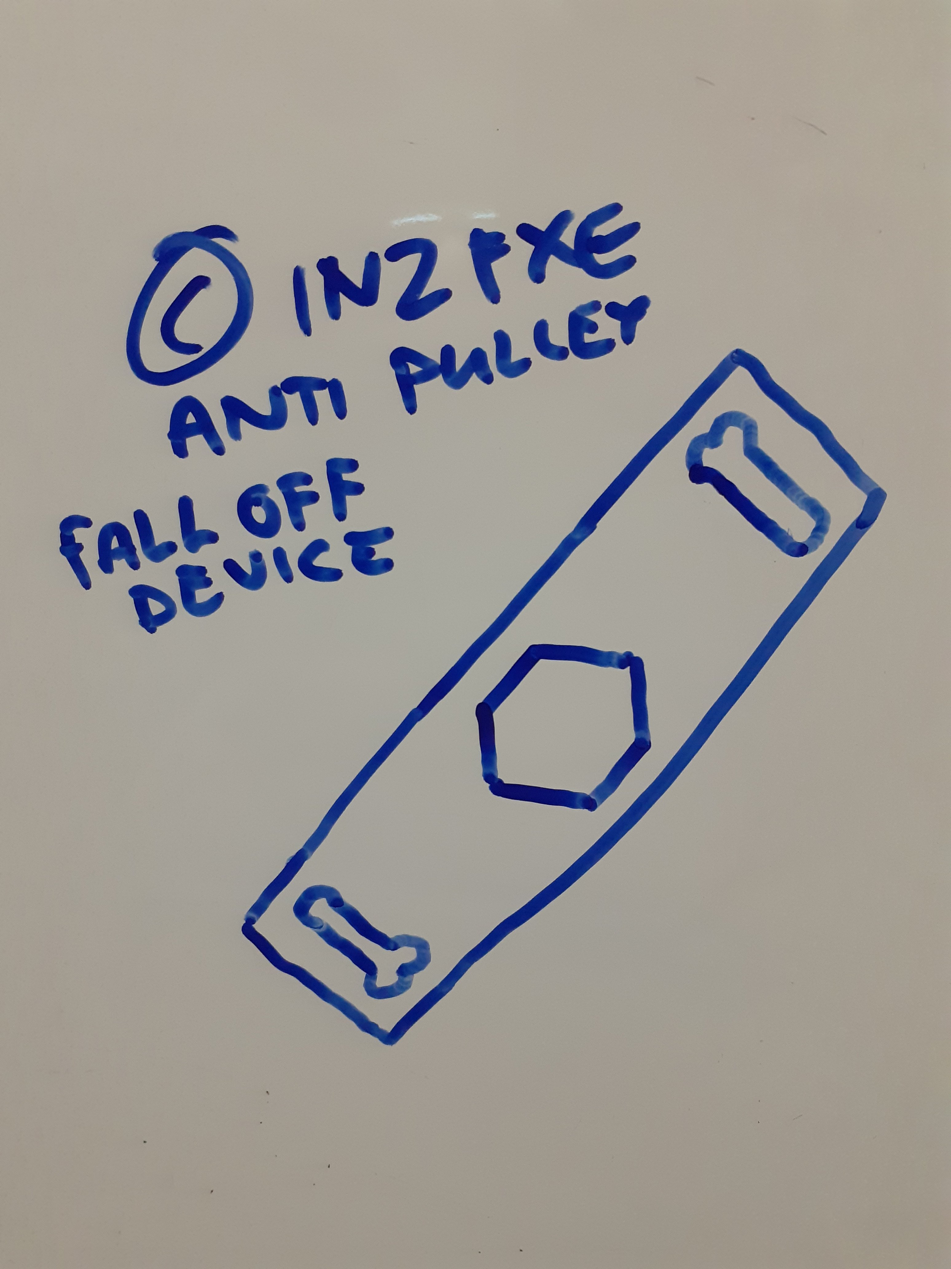
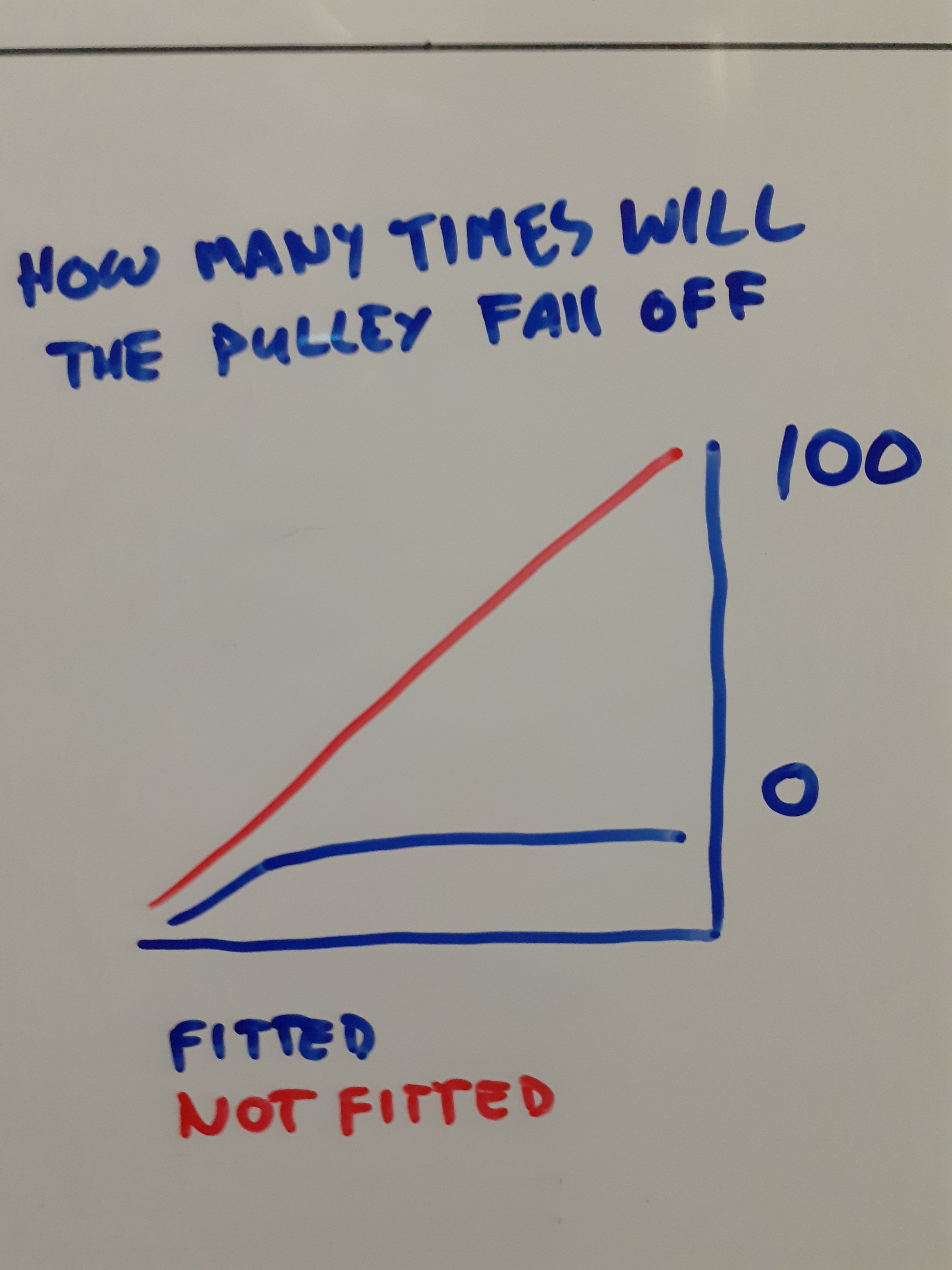
I designed a device for you that bolts on to your pulley to stop it falling off and also supplied a scientific graph as I know how much you love them
3 points
-
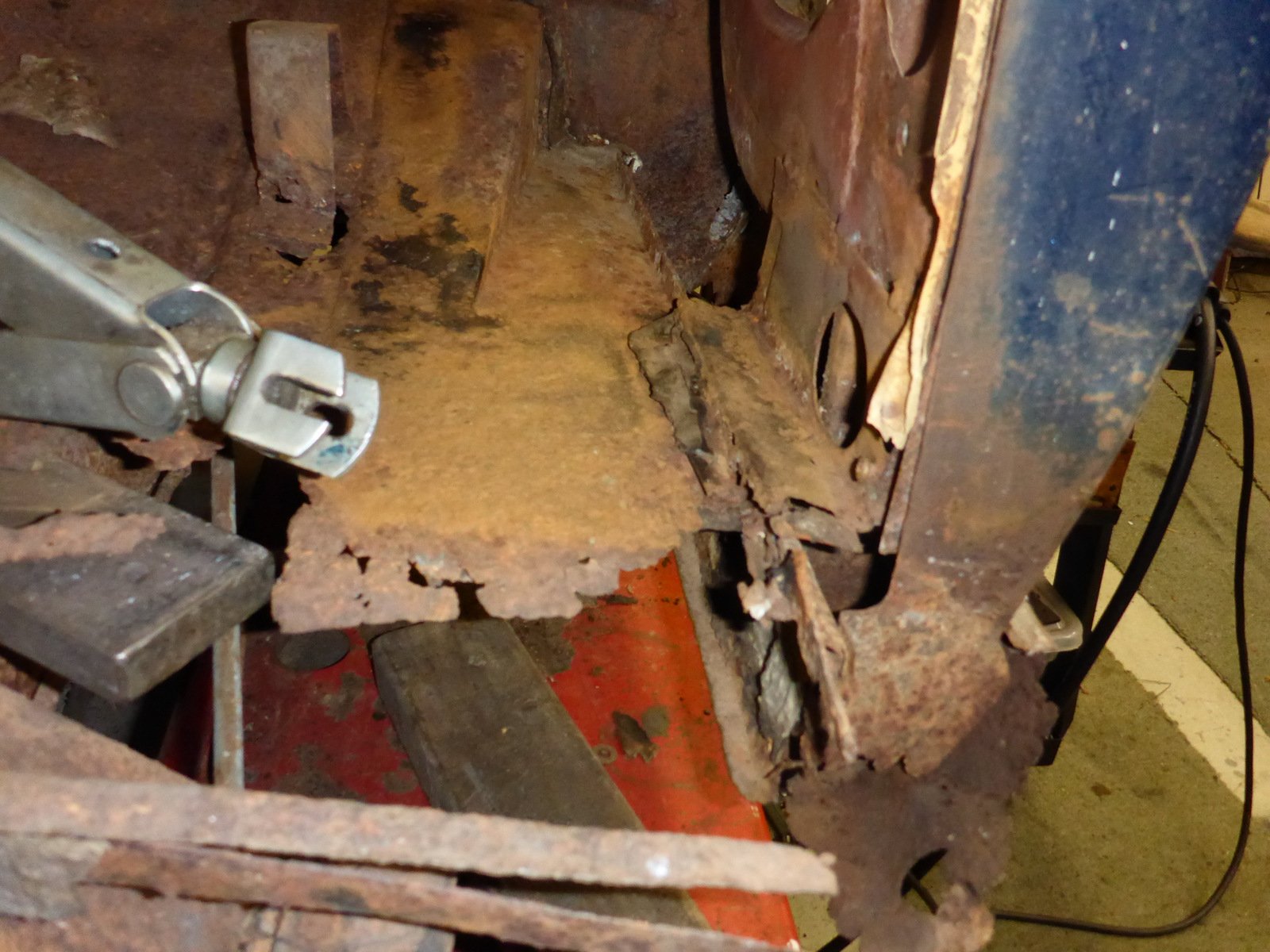
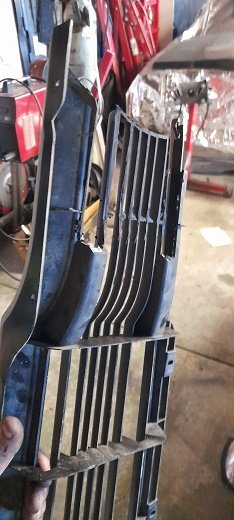
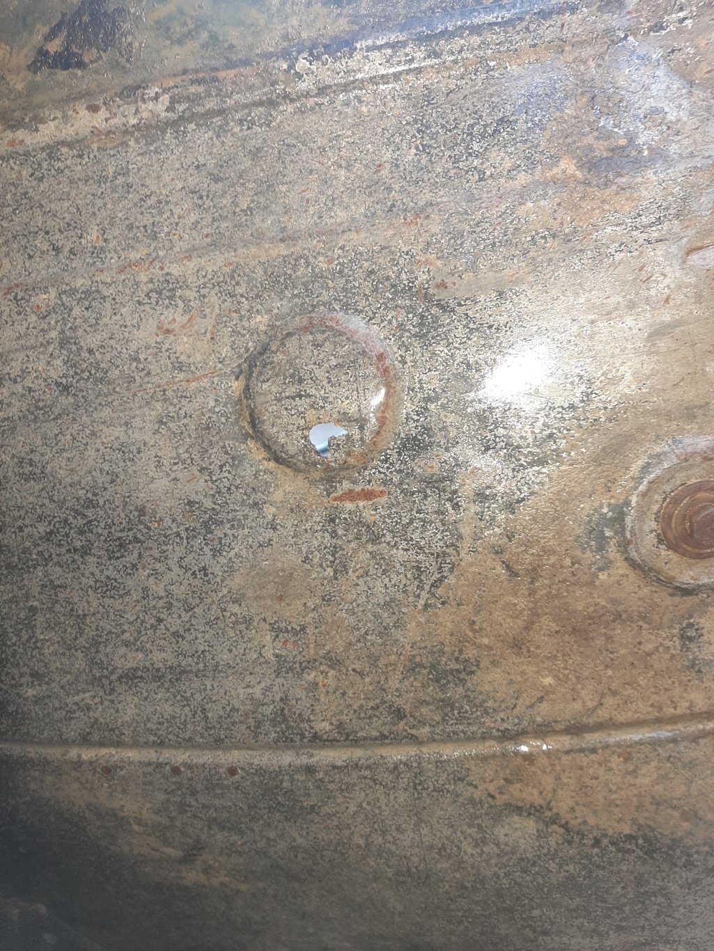
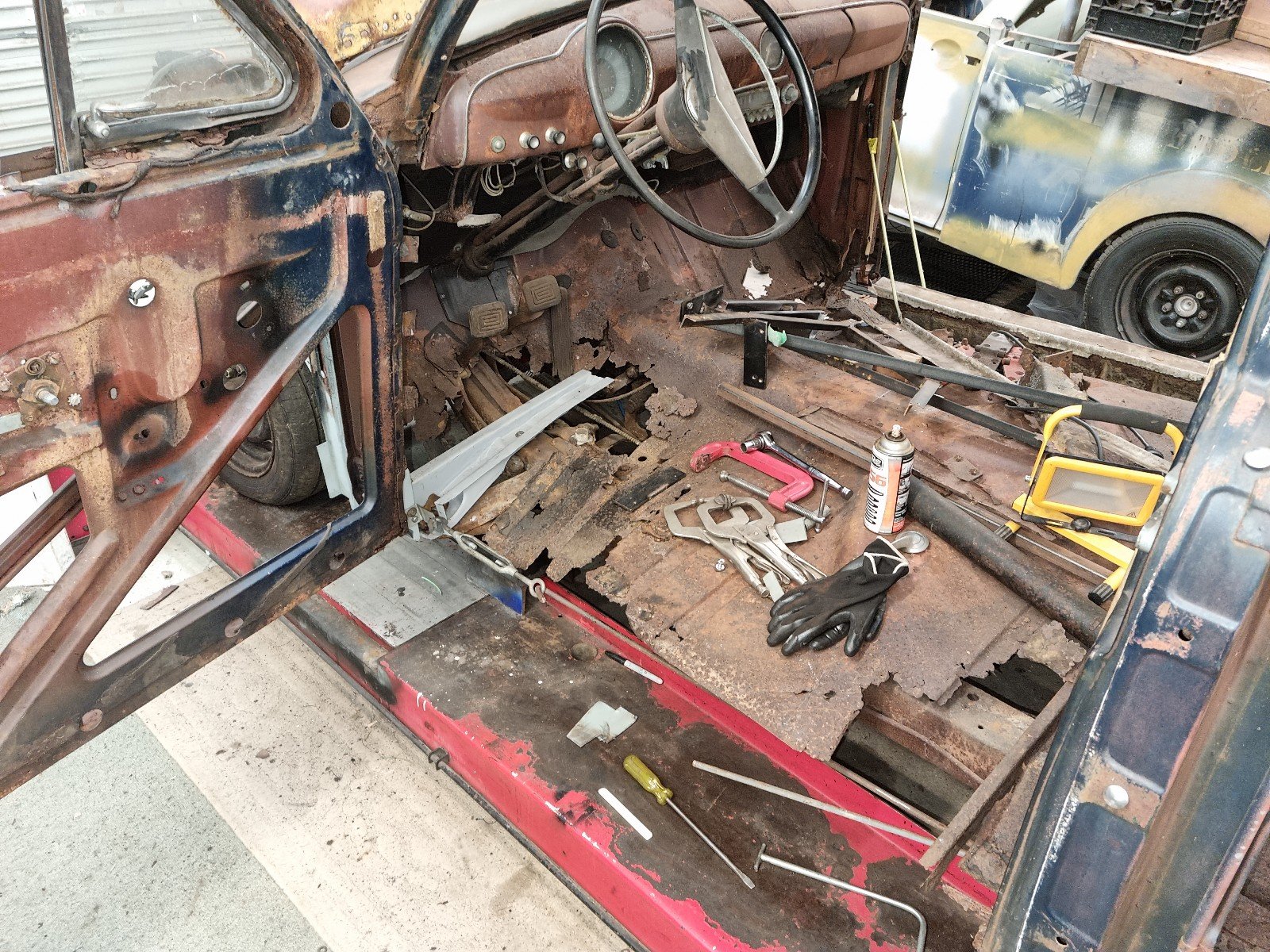
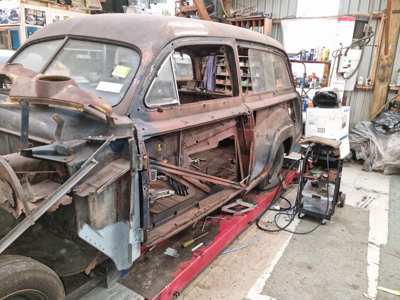
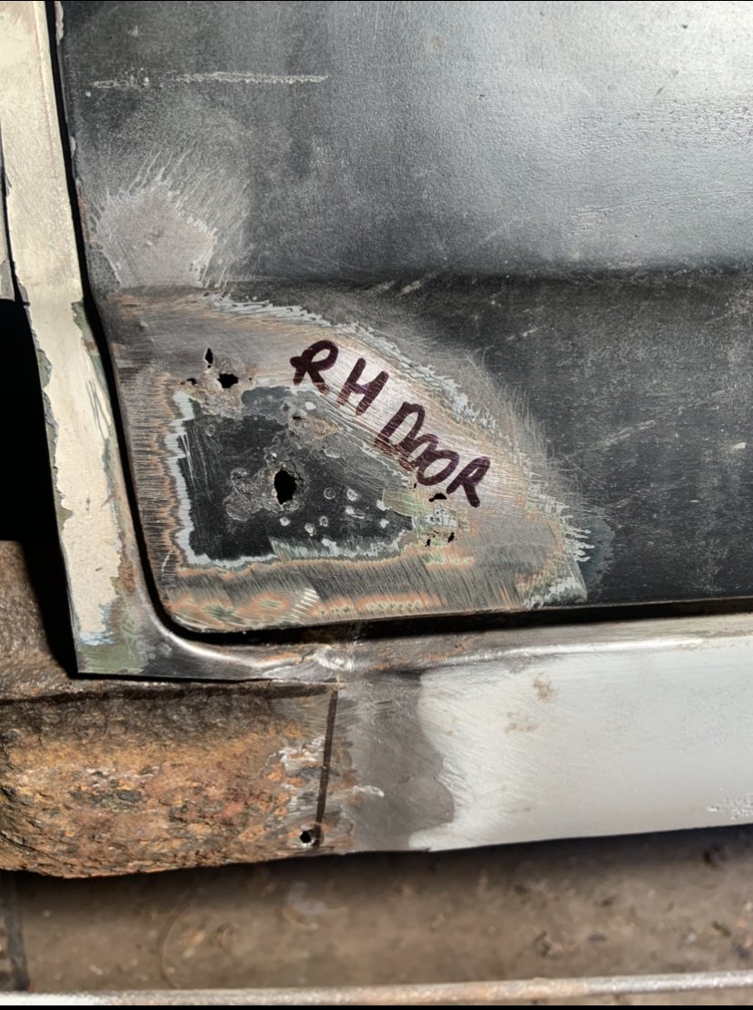
Well that was never going to fix itself was it.. rust bomb with a lit fuse! Remember I said I spent ages with air and vacuum yesterday getting scale out? Missed a bit.. Thankfully the skin is 95% mint, it’s just the very front ‘nose’ section that’s let go. Plenty of hours in the frame though. I’ll clean it up and rust kill it and paint it then put the skin back on before I repair it so it doesn’t get out of shape.3 points
-
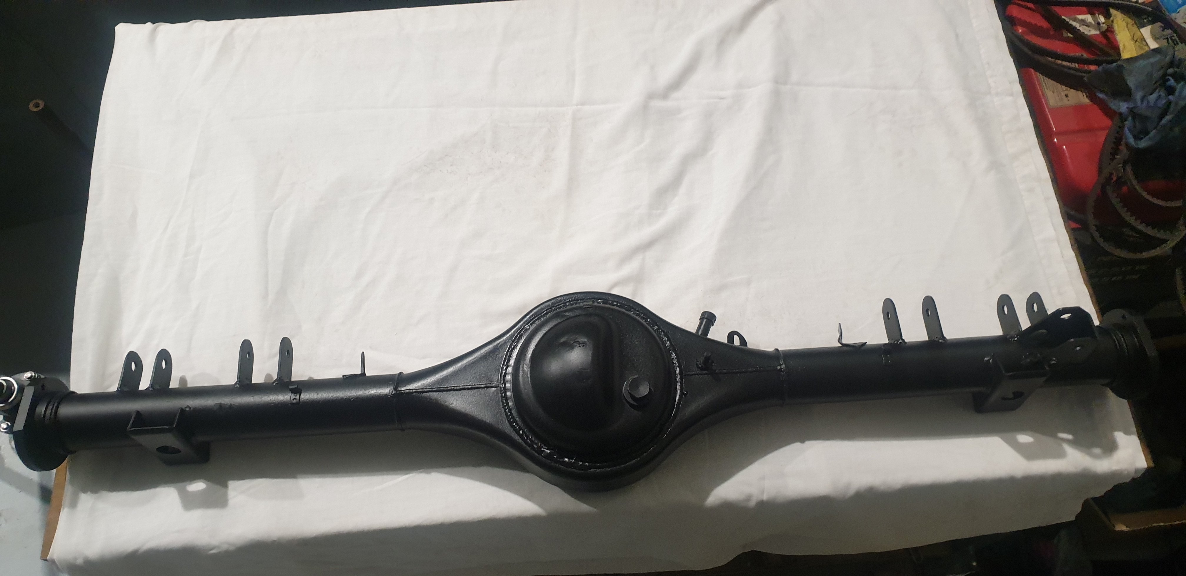
Diff housing all primed and painted.
2 points
-
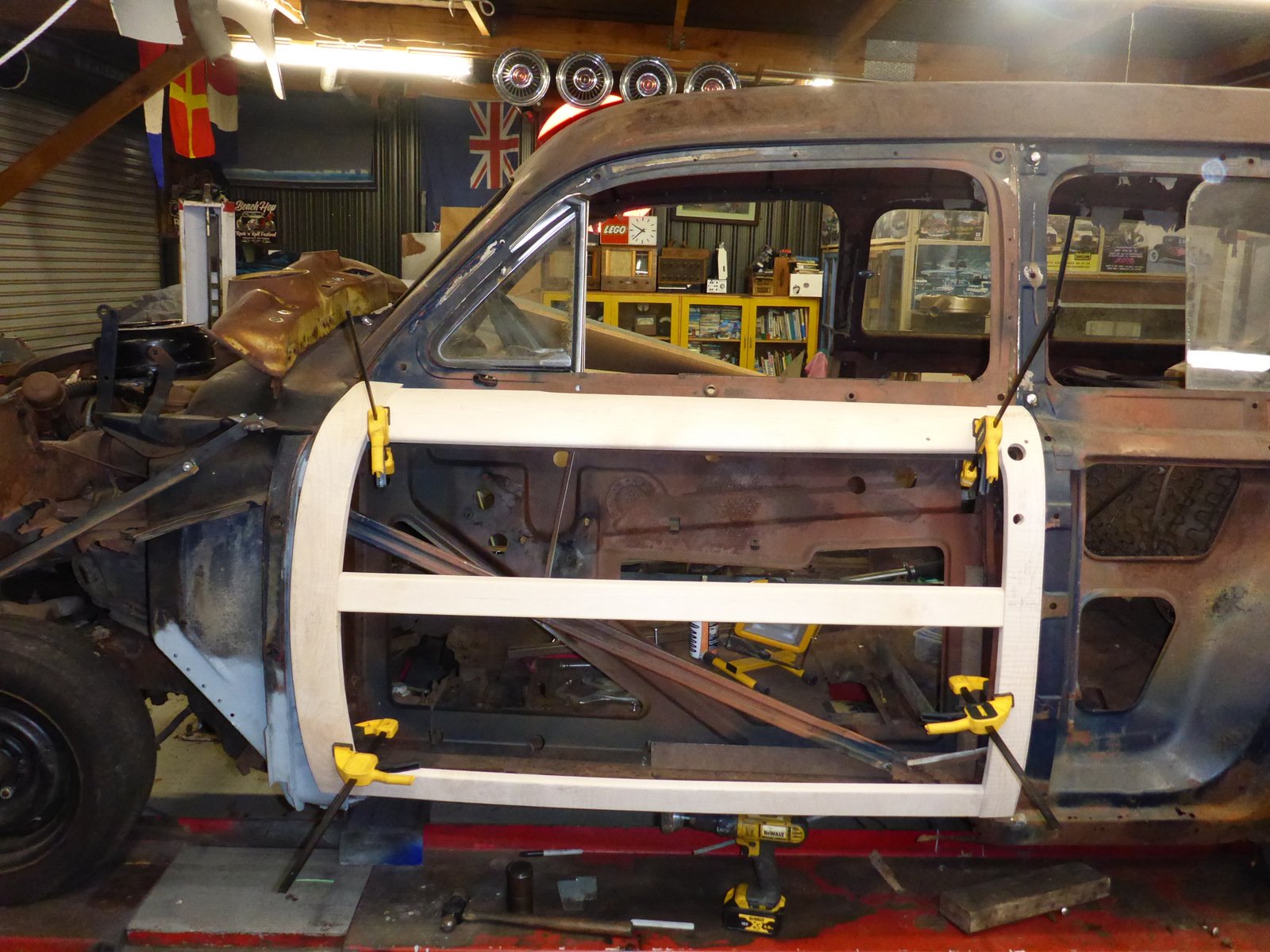
Trying to be sure I have the overall alignment right before further cutting. Pulled out the door lower wood piece and clamped it on. Looks OK I think? I'm a bit bothered by the way the reinforcing plate between the pillar and the floor is bent to less than 90 degrees.
2 points
-
Fucking dodgy wiring in that shit hole mate. Bikes shit too. <32 points
-
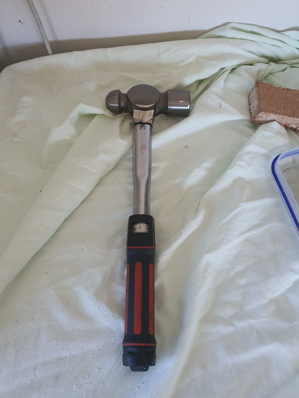
Built this for an old workmate who absolutely is the epitome of "everything is a hammer" so much so all torque wrenches got referred to as torque hammers on site. It still functions and will dampen shock if you adjust it down , pretty cool kind of dont want to give it to him.
2 points
-
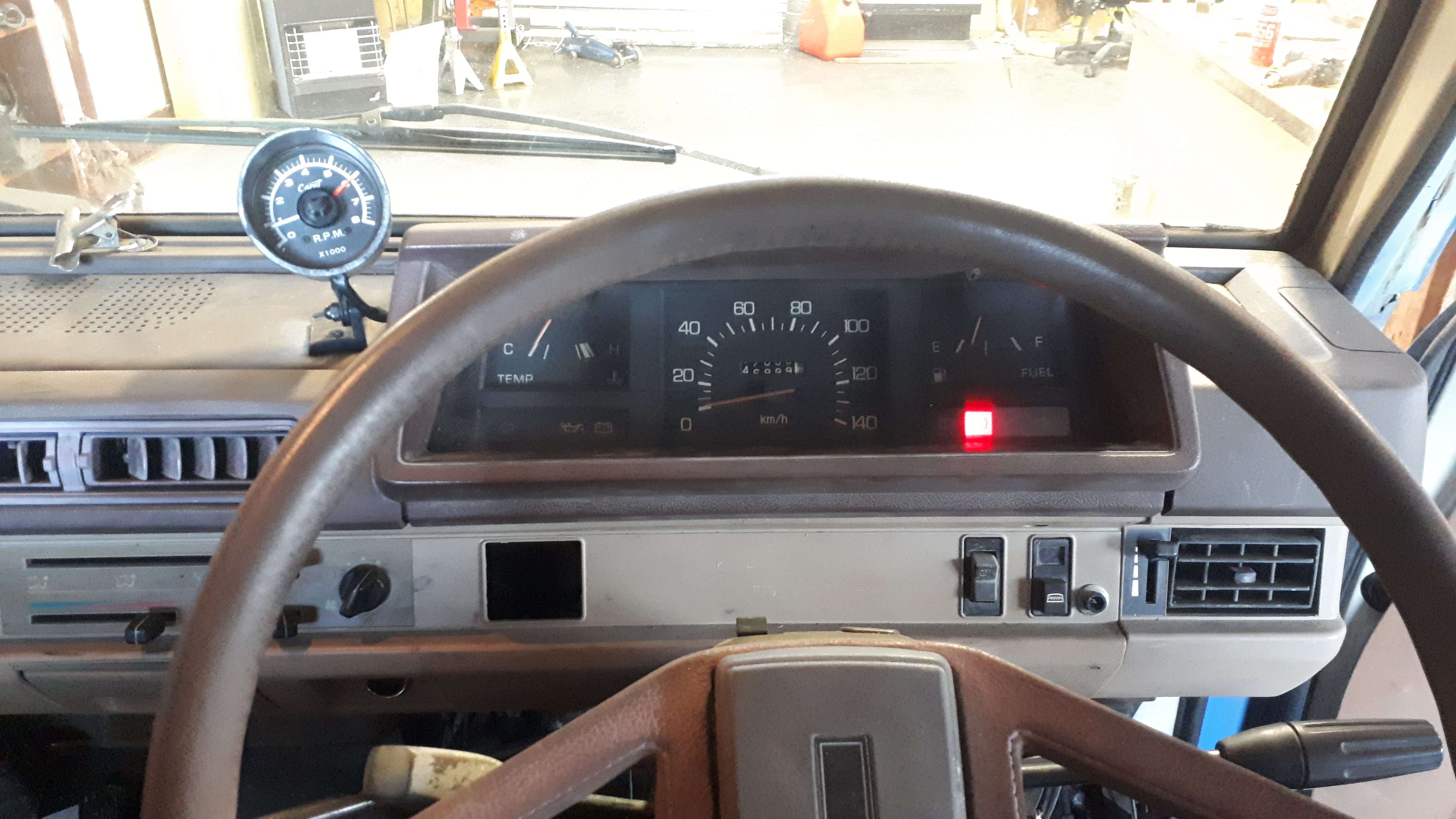
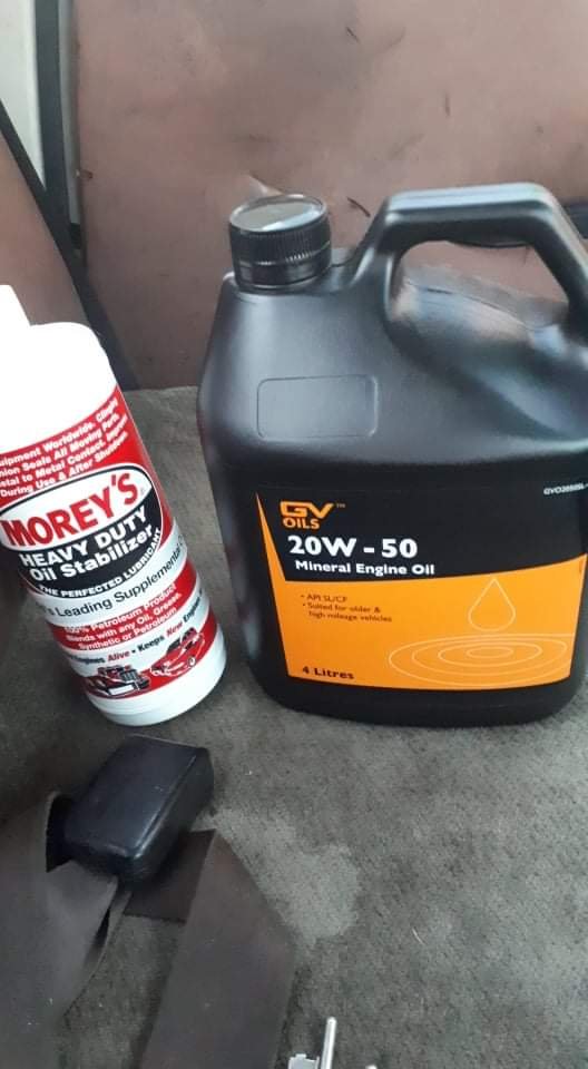
This has been a bit of a sack. Blew a heater hose cos the coolant system was pressuring because the headgast was leaking. Then because of the blown hose i think the headgasket went properly and it started gushing collant out the radiator cap So today i replaced the headgasket. Was also lazy and didnt do the stem seals. Meh. Front brakes are also real grabby. Fuckin drum brakes Put some moreys in the motor to stop some of the smoke.... Also fitted a tach so i can see it doing 5000rpm at 100k Winning combo
2 points
-
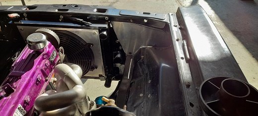
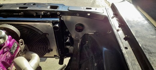
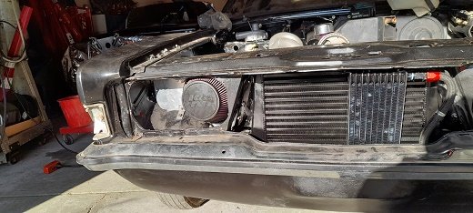
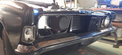
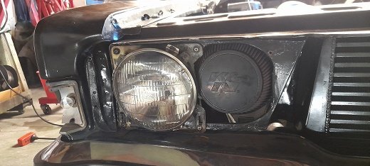
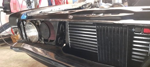
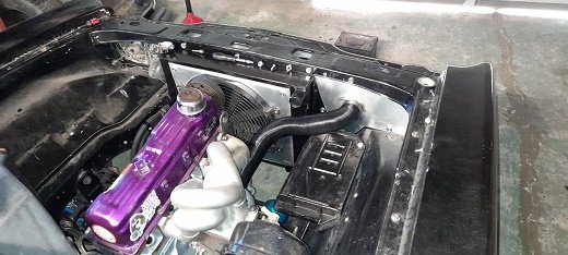
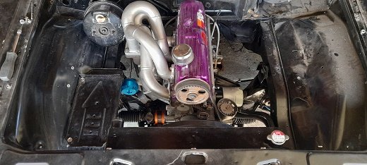
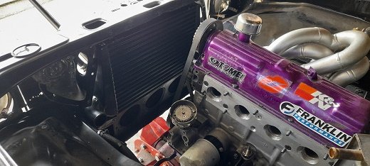
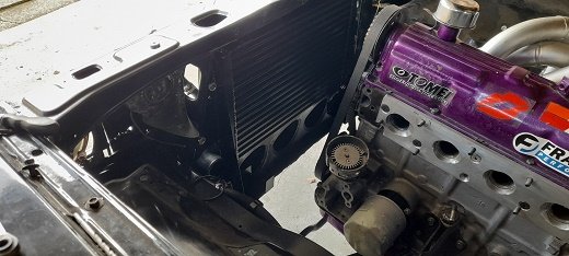
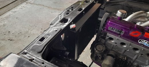
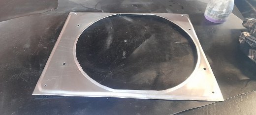
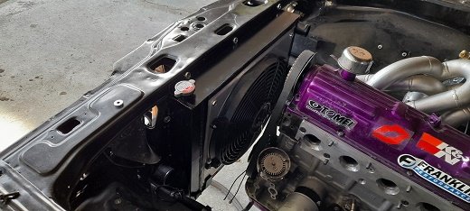
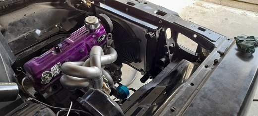
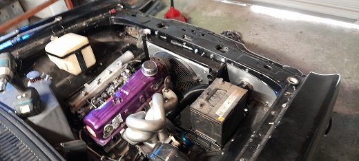
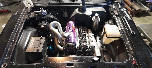
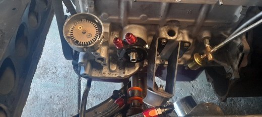
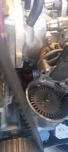
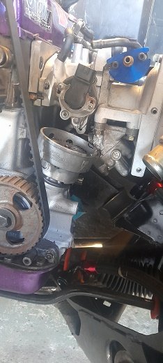
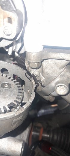
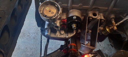
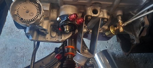
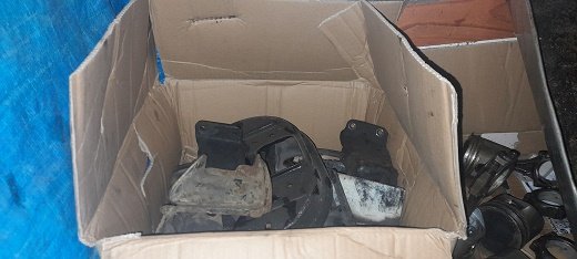
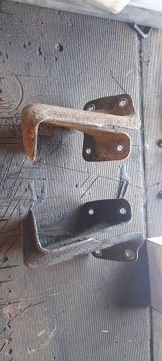
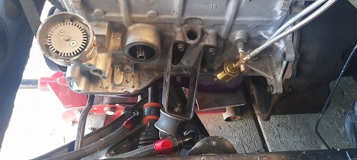
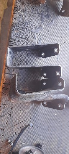
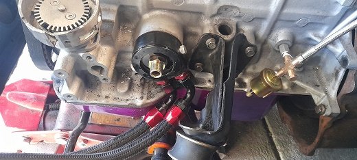
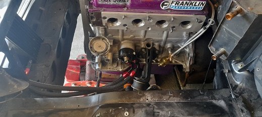
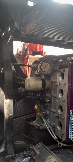
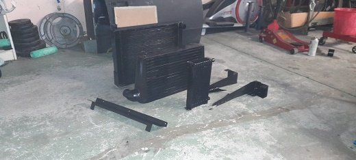
so you know when you think its going to be a nice easy straightforward job..... oil cooler was mounted...all i had to o was put the oil sandwich plate on and run the lines.. i center bolt for the sandwich plate must have been put in a real safe place as i cant find it.....so after over nighting parts from Auckland i bolted the sandwich plate on ran the hoses and cut them to lengh...........then i put the inlet manifold on and it seems that all the IACV stuff is in the way and then so is the dizzy...there is next to no room under there now and also noticed that the dizzy housing is also touching the IACV ( will clearance that with the flapper disc) and it seems that if i turn the sandwich plate down it hits the block and no room..turn it to the back and the engine mount is in the way. so i thought about cutting and shutting the engine mount and then i remembered the rusty old parts wagon had some pinto mounts i had never seen before ...so out came the mount box and these are that mounts that came on the rusty wagon the problem area mount mount comparison and bingo......problem sorted......well that problem..i need to get ne hoses now as the ones i cut dont fit. on another note i made mounts for the radiator 9thats a 70mm dual pass rx2 rotary radiator). then pulled the oil cooler , intercooler and radiator and mounts out and gave them a nice clean paint. oil cooler in intercooler in radiator mounts in radiator in made a shroud for the 14" fan shroud and fan in now tha battary tray hits the inlet manifold no matter where i put it ..and luckily enough these came in right and left hand drive and the sides of the engine bay are the same ....so i moved it to the drivers side...trimmed a corner off to move it back a bit (dont worry about the booster as i dont have brakes yet but i am planning on cylinder bolted to the fire wall and run a remote booster) and the air filter.....i made a head shelf hole cut for filter adapter filter in had to trim the light bracket also had to clearance the grill for the filter and oil cooler works well ......cant see much at all unless you look hard intake pipe for the turbo and the engine bay is starting to look much fuller..just got to mount over flow tank and washer bottle and breather tank on the passneger side.
2 points
-
2 points
-
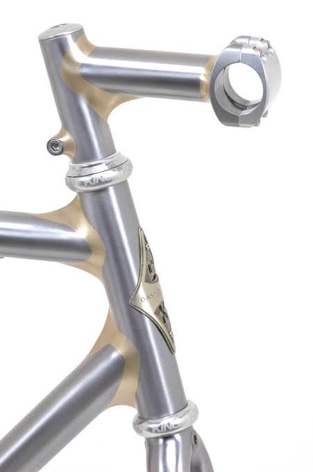
I use manganese bronze rod and gas. My frame joints look like his large fillets where he used the bigger rod. Never had one break - and they've been crashed too. They're mild steel tube and the big, softer fillet is a good match and won't crack. What is typical is the lack of mention of nickel bronze rods. They don't seem to be used in the US. Strength is a lot higher so a smaller fillet can be used. Where you're using high strength tube - like your CrMo tube - I'd use nickel bronze as the filler rod. It's a very good match for the material.1 point
-
Shit yeah, looks so good if you file it all down
1 point
-
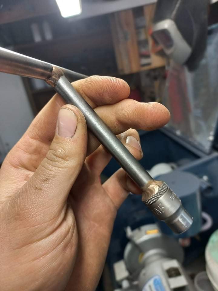
Shit yeah this is mean, bring around some scraps and ill give you a hand. You shouldnt need a pedal even though alot of people use them just use the right amperage and be more fussy on your torch angle. If your keen I have some tig brazing rods ive been wanting to use on a big project.
1 point
-
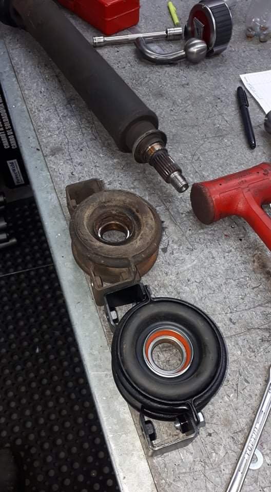
Did this this morning at work. Centre bearing was noisy and loose. Hilux centre with the crown housing bolted around it. Sorted Much quieter
1 point
-
One part I neglected to address in my previous post about the driveshaft was the sliding yoke. It was seized, and no amount of pretending it wasn't was freeing it up. The sliding yoke sits at either end of the diff half of the drive shaft. Sometimes it's on the diff end of the shaft, or in my case, it's in the middle near the center bearing, depending on where BL felt like assembling it. Either way, it's a crucial part of the driveshaft. As the rear axle travels up and down in normal driving, the rear section of the driveshaft has to raise and lower with it. The problem is that the axle travels in an arc, which means the distance from the axle to the center hanger bearing increases and decreases slightly as it moves through its travel. To account for this change in distance, the driveshaft needs to be able to change length. This is done with the sliding yoke. Inside the yoke is a series of strong splines, which mate with another set of splines attached to the end of the driveshaft. This allows the shaft to transfer power through it via the splines, but also slide in and out to account for the movement. A cap, spring and seal stop the spline from coming all the way out. My yoke didn't slide at all. It was completely compressed at its shortest length and would not budge. I tried many things to free it up, including filling it with penetrating oil and hitting it with various hammers. Nothing. I even tried hanging it and seeing if gravity would free it up (it didn't). I tried a few other things with no luck, but the one thing I was lacking was tension on the spline. Hitting it to shock it was fine, but if there was no tension pulling the two halves apart then I was only going to get so far. So I had a brainwave (it hurt). Two ratchet straps and a very sturdy workbench later, I had this contraption I ratchet strapped each end of the shaft to a leg of the bench and put tension on the shaft. With one hand I grabbed the yoke and leaned back, putting even more tension on the shaft. With my other hand, I hit the flat of the driveshaft with a hammer. Sure enough, after a few hits, I saw movement and then with a POP it fully extended. I unscrewed the cap at this point, which reveals the cork seal and washer. The cork seal is known for being pretty chewed up and is unobtainable new now. Thankfully mine was in mint condition. And for the first time I could see the splines. The old grease was black and disgusting, and the splines had obvious signs of surface corrosion. One thing to make sure of is that both halves are clearly marked so it is reassembled in the same location. I scribed lines into the yoke and driveshaft and then marked it with a white paint pen. The spline isn't keyed, so can fit many different ways. The main thing to take care of is that the UJs are in phase, which means they both have to be in line with each other. With the spline removed it was time to get cleaning. All the old grease was cleaned off with brake cleaner and a toothbrush. Which revealed why it was seized together. All the teeth had surface rust to some degree. This was binding with the internal splines in the yoke. A good wiring brushing quickly got rid of most of it, showing the splines to be in good shape otherwise. The splines were then slathered in grease ready for reassembly. The internal splines in the yoke also got a good clean Once I was satisfied with the condition of the splines I packed the yoke with grease and slid the driveshaft back in. And wound the cap back down over the seal. A quick wipe to remove the grease ejected out the breather, and we're done. The joint slides freely so should do the job nicely. With that done, the driveshaft had been completely overhauled now and is finally 100% ready to go back in the car.1 point
-
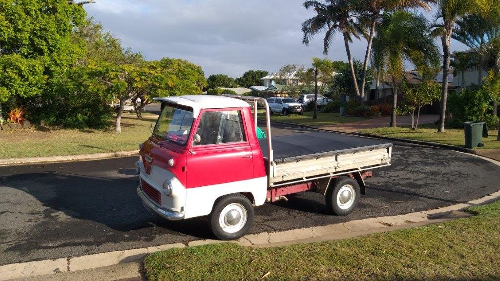
And then in other news a fellow Thames enthusiast who is visiting the area dropped by for a yarn. This sweet little truck is fitted with a V8 and associated running gear out of a Leyland P76. The cab has been converted to tilt for full engine access.
1 point
-
Been a while, last time I drove this was during lockdown last year. I start it every now and then otherwise the clutch sticks on. The clutch has been the bane of my life since I bought this car, now it'll lose its fluid in about 2 months so I bit the bullet and had the clutch master/slave resleeved and new seals at Canterbury Brake and clutch (their quote was literally half the price of safe r brakes which was $2-250 per item. Would defo recommend. Last year I was at @RUNAMUCK's place for a meat and was commenting on the nice custom radiator in his datto. That led to this Custom mk3 zephyr radiator for a fucken good price, doesn't fit quite like the original but nothing a couple of spacers won't fix. Just need to clean the system out before I mount it. What I thought was bad rust at the bottom of the pass a pillar turned out to be just some light surface rust from when the front screen leaked, treated that. That leaves just one thing and I can get it another wof ready for the drive up to golden bay. If anyone has a good hook up on exhaust fab that would be great (I have zero time, and I'm out of mig gas)
1 point
-
It's been a while since I had done any work on the Marina. The Tacho kinda progressed in the background, but most of the focus had been on getting the Carib going. But with the Carib on the road, I turned my attention to the Marina again. One of the things that had to be done before I could attempt to move the car under its own power was to rebuild the driveshaft/propshaft. I knew from when I first went under the car that the center hanger bearing was completely shot, and had collapsed, so at the very least that needed to be replaced. Ages ago (about two months ago) I slid under the car and removed the driveshaft. Hanger bearing was looking a bit sad I'm glad I took it out and checked, it turns out the bolt that secures the two halves together was... missing. There was also play in at least one of the universal joints, and it wasn't the one secured by clips. Two of the three UJs are secured by a process called Staking, where they physically deform the metal around the edge of the cap to hold it in place. This is a real pain because it needs some skill and usually a bigger press than I have to replace them. You can see better detail in this example image A normal universal joint is secured by a big circlip in a groove, which is far easier to work with. This prompted me to reach out to a fellow Marina owner and purchase a spare driveshaft off him, which although had a failed center bearing too, used Circlip style UJs and had the securing bolt for the two halves. I finally got around to attacking the replacement driveshaft the other day. I wanted to refurbish the whole thing since it was old and I didn't want to have to pull it out later to replace the UJs. There is a great video by Chris Fix on how to replace UJs. He makes it look easy, but I hated this job. First I cleaned it up a bit, marked the alignment and removed the clips with a pair of circlip pliers This end was pretty straightforward. Big socket (24mm impact) underneath, and a smaller one that fits into the recess (14mm impact, 16mm normal) on top and using a big hammer, smash the 14mm socket down, pushing the UJ cap out the bottom. It came apart more or less with no trouble. Push the joint down, pull the cap out. push the joint back up, pull the cap out. Done. To fit the new joint, I found it best to lubricate the recess you are pressing the caps into with clean ATF, and then press them both in together using a bench vice. This helps to press them in square. I didn't do this for the first couple, I used the method of hammering the new caps into place. I did unfortunately find out why they recommend sealed joints without grease fittings... There is not enough room in the joint for the long grease fitting, and you would risk breaking the fitting off when the joint moves. These joints were very cheap on clearance though, so I persisted anyway and dealt with that later. One end of the driveshaft done. The new joint is smooth and feels great. A few pumps of the grease gun and it was ready for action. Kinda. The next joint was well jammed in place, to the point it blew the end out of the cap before dislodging it You can tell from the state of it when it did come out that had some issues. Being a sealed unit, you can't grease it, so once the grease hardened it was all bad. Fitting the replacement wasn't much better. This was when I was still using hammers to fit the caps and I came really stuck on this second UJ. I can only presume the caps weren't going in quite square, which meant they were binding. After a few tries I moved to the press, which only did one thing, it blew the new cap to bits. But it also scored the cross piece So no, I'm not perfect, I do sometimes make stupid mistakes too. I took a little break from that UJ here as I needed another new one to continue and moved to the hanger bearing. I tore the rest of the outer part off and used a hammer and pry bar to carefully drive the old bearing off. After a little bit it popped off With the bearing off it was easier to handle, so had a go at replacing this UJ. This was the only one that is greasable, and as I later found out this is because there is a small recess in the flange to allow space for the grease nipple. You can just make the recess out here. This was another one that I was having a battle with, but instead of trying to use more force to press it out, I just grabbed the grinder and used a cutoff wheel to make quick work of it. Take that! The new caps pressed in fine, using my newly honed method of starting with the flange, and pressing the caps in with my vice until they are flush, and then tapping them in the rest of the way with a socket and hammer until the clips fit in the recess. A couple of taps on the flange frees the joint up. Another rookie failure here, I didn't notice there was a recess for the grease nipple at the time, so fitted the joint in the wrong orientation. Argh. Without another new joint to replace the damaged one, the only thing I could do was fit the new center bearing. This was as easy as popping it into place, with the longer side facing the splines and then tapping it down until it bottoms out. I used a big socket and an old bearing race as a spacer. I had a new joint arrive a couple of days later, so in that went. I initially tried fitting it to the existing flange, but it didn't feel right, so went with my gut feeling and pulled the flange off my original driveshaft, and used that instead (thankfully it was the one joint that wasn't staked). It's not ideal, but I feel like the flange may be damaged on the other one which is why I was having so much trouble. The joints pressed in with no issue. Ignore the placeholder bolt, that was just testing it was a 6mm grease fitting thread. The other two joints were 1/4" UNF thread. Speaking of, to sort my issue of all the grease nipple being too long and fouling the joints, I went out and bought some short grease nipples. These clear with ample space, but were an utter bastard to fit. They have a bigger hex than the longer ones, and there is no room to actually get anything on the hex when you screw it into the joint. I ended up tightening them up one flat at a time with the spanner sticking straight up in line with the fitting. In hindsight, I would get the sealed joints, but if I couldn't, I would get some grub screws with the correct threads and use them to plug the holes after greasing. Either way, the joints are all greased, and the holes plugged. With all the joints replaced and the new center bearing in place all I had to do now was refit the two halves of the shaft. The spline is keyed with a double width tooth, so it can only fit in one orientation. Take note before sliding the spline completely down that it's easier to start fitting the bolt in the center when the shaft is slightly apart as there is limited space with the joint in place. I did the bolt up as tight as possible, and then bent the locking tab over. Now all I need to do is fit it back to the car, but that can happen another day since I can't be bothered rolling around on the ground right now. Once that's in, since the clutch is bled and working, all that's left is new tyres, which are currently in a stack next to the car waiting for me to strip the old tyres off and paint the wheels. Getting real close to moving under its own power for the first time in about 25 years.1 point
-
Ooooooh yeahhhhhh
1 point
-
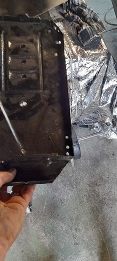
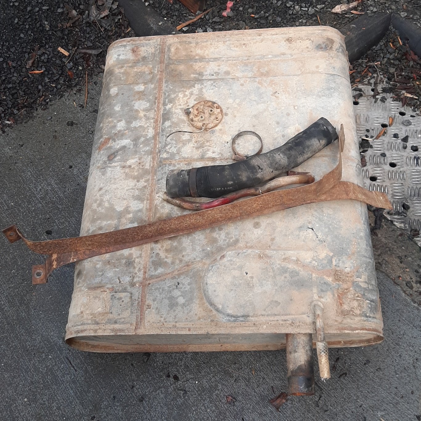
Dropped the fuel tank. Filler and vent rubber had been replaced with radiator and garden hose respectively Was empty which i took as a good sign. Its dented underneath but looks watertight and is galvanised. Level sender not looking so good. Floats are cork. See what happens after an overnight soak in vinegar. Thats just nasty After a rinse with the hose this appeared, looking al the way through back out the sender hole. Dang it. Plan was to take this and the radiator to get dipped and cleaned. Radiator has a split too. Hopefully the whole bottom of the tank isnt thinned from the inside out. Will see what the man says.
1 point
-
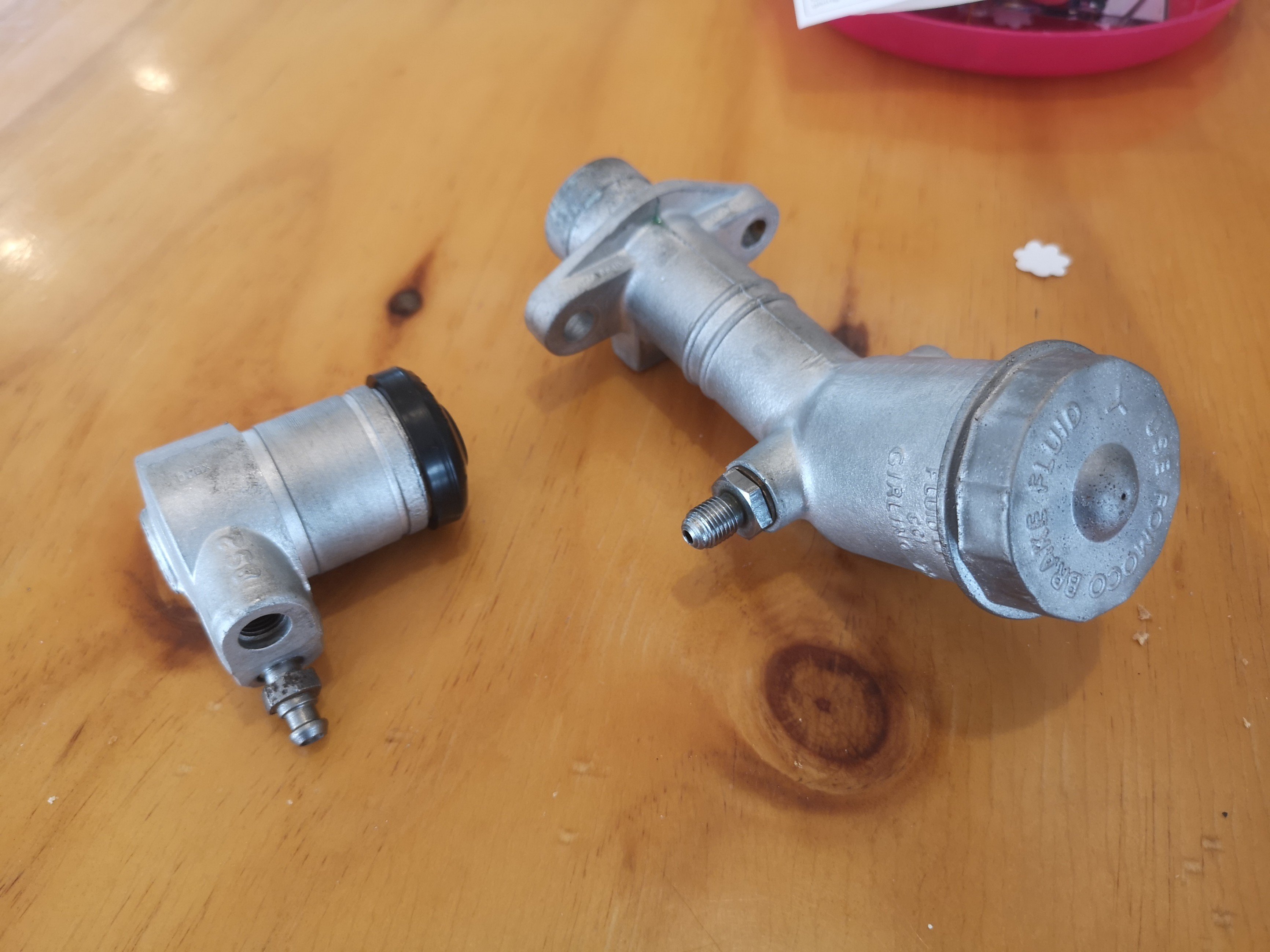
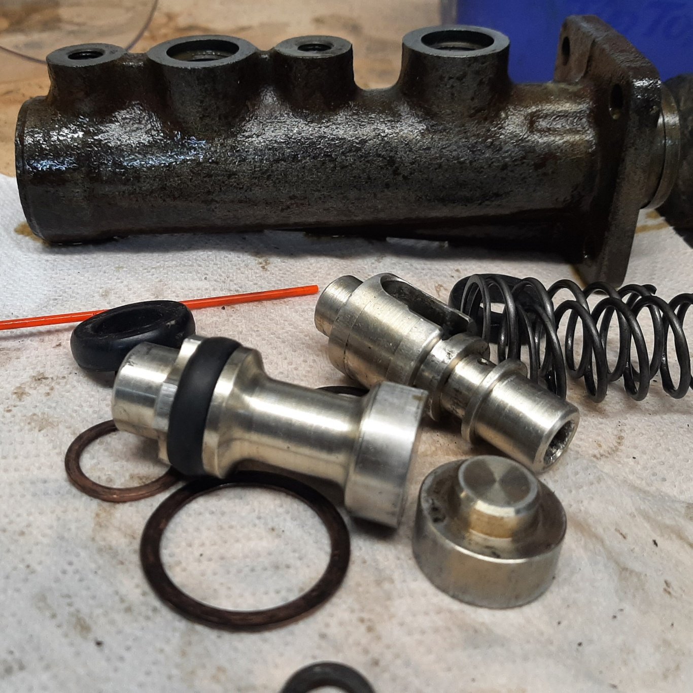
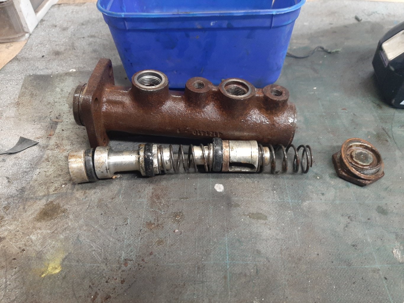
Brake master cylinder is cleaning up nice. Got a rebuild kit to go in. Trying to figure what intake to run. The potential performance advantage of the twin barrel car manifold over the single Solex 32 BIC is obvious But so is the size. Might rub on the cab. Fitting a different carb with the gubbins mostly facing the head would probably work too. Maybe later. Anyway, variations on the Solex BIC single carb was used in many small and medium cars from the 50s to the 70s, and much later in the third world so parts are plentiful (and cheap!) and so now have a 'Willys Jeep' full rebuild kit on the way so will start with keeping it originale.
1 point
-
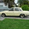
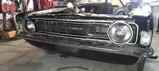
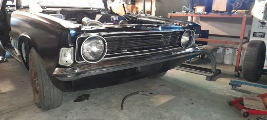
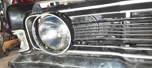
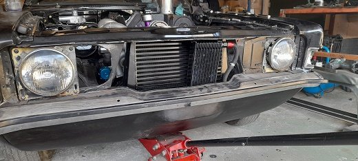
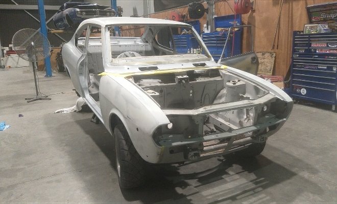
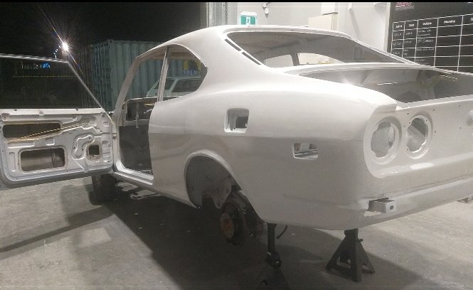
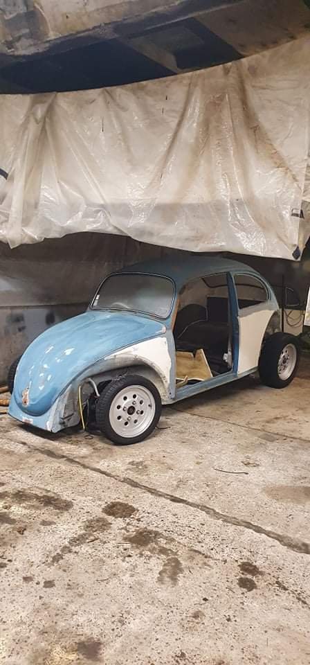
Got all the running gear buttoned up so first time outside with all the panels on (during the daytime) I can take some decent shots of it. With some new rubber and painted rims it'll look sweet, need to strip all the haggard paint off the bumper too.
1 point
-
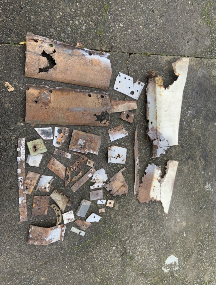
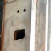
Dismantled all the taillights and put some zinc primer on the worst ones. The better parts have been sent to the molasses barrel for a soak. Should be enough parts to get two good omplete units. Also have the structural part of the drivers door pillar done and it closes and latches ok. Next part is probably the sill and where it attaches behind the door. Stay tuned.
1 point
-
It feels like it's been a huge uphill battle getting a working tacho in this car, but I think I have finally mastered it. Over the past few months, I have somehow ended up with a few different clusters, including two with the elusive tachometer module, and the one with the non-functioning clock I previously made a post about. The first three dial with tacho I bought from Trademe. It was the correct Aus cluster, with the lower 5500RPM redline, and a couple of other small differences as I would later find out. Eager to get the tacho in and working I started to dig around the wiring diagrams to work out what I needed to do. I had heard rumours that the wiring was already in the dash, behind the cluster, and sure enough, after some poking around, I noticed a white wire tucked away with a joiner in the middle of it. This tracked with what I was expecting to find based on the wiring diagrams. It was a big loop in the harness. I fished it out from behind the duct and unplugged it. A couple of quick checks and I was sure it was the coil trigger for the tacho. On the cars without tachos, this is just looped in the dash but needs to be connected or it cuts power to the coil. I guess it made it cheaper and easier, to just use the one harness. The back of the tacho unit has corresponding bullet terminals So I plugged it into the dash, and bam, nothing happened. Well, the alt/oil lights worked as they should, but the tacho was dead. I was a bit miffed Nothing more to do then but to get to disassembly and find out what's wrong. The tacho unit is held into its housing by a couple of screws through the back, and the fascia/glass in the front. This is what the module looks like removed. Having already googled "why does my Smiths RVI tacho not work" I could already see something was wrong. Those four holes in the foreground, under that red wire? Yeah, according to google there should be a transistor there, and it's crucial to the operation of the unit. The solder pads had clearly been messed with too. It looked like someone had desoldered the component with a blowtorch. I hit the seller up and asked if he knew why it's been molested, and he just pleaded ignorance and fobbed me off with a "oh well, it's an old part". I suspect the capacitor or transistor had failed at some point (which is common) and someone tried to fix it. Failing to have the right parts on hand or something, they just chucked it back together and set it aside. As fate would have it, a fellow classic car sufferer on a forum I'm on knew I'm suffering the Marina affliction and mentioned that he had come across some Marina bits as part of a garage clearout, and would I be interested in a cluster he found? Heck yeah I would! The legend donated this to the cause, so a huge Thank You. So, this was the second tacho cluster I have. It came in a tidy surround, but it was brown, not black. No issue, They are easy to swap, and I only really needed the guts. Differences to observe. The silver rings around the dials, instead of the black the Aus cars have, the 6000RPM redline on the tacho face (ignore the askew tacho, I had already started to disassemble it), and the different markings on the fuel and temp scales (0 instead of E, and adding the N to temp). One final difference I didn't notice initially, is the warning lights are different, with some either doing different functions, or in the case of the indicator telltale lamps, not there at all. The UK cars seem to use one single green light to show the indicator is on, whilst the Aus cars use the two spaces above the center dial as left and right signals. *removes anorak* Right, so this cluster. Excitedly I plugged it into the car, and we had some success. The tacho moved! But it barely exceeded 1000rpm when revving the engine. I think this one may have been suffering from the known issues Smiths RVI tachos suffer from (bad capacitors), but instead of messing around with the old inductive RVI style guts, I spent a hefty whack of cash on the Spiyda RVI-RVC conversion board. The original RVI tacho is current sensing, so it intercepts the power feed to the ignition coil, and by some wizardry senses the pulses and creates a signal for the tacho to output. The issue with this is apparently the tacho only works with points, and in the future I want the option of upgrading to electronic ignition without having to replace the tacho again, so it had to go. The Spiyda board removes all the existing guts from the tacho, and replaces it with a new board that reads the signal from the negative terminal on the coil (like 90% of tachometers). Heck, it can even be fed a signal from an ECU. It's pretty swish stuff. I stripped the second tacho out of the housing, and you can see the missing component of tacho one here; the silver can is a special transistor. I started with the guts of the first tacho since that one was dead in the water anyway. Spiyda has extensive instructions on its site, here, so follow those, but this is how I went about it. The first step is to remove the needle. You don't need to mark where the needle sits, just make sure the mechanism is against its stop when you refit the needle. To remove it I used an old business card with a notch cut in it, and a sturdy fork. The business card is to reduce the risk of damage to the face. A swift lever upwards popped the needle off. Two little screws secure the face. The kit comes with a tiny screwdriver to remove these. Now cut the power feed wire, and the two thin wires to the mechanism and remove the two screws holding the circuit to the frame. It should pull off the front. The new board then gets screwed in place Now solder the wires in their respective places (in my case the black and red wires had to be swapped). and you're ready for testing and calibrating. Now, I did make a mistake in the above photo. It turns out that the video I was following, made by Spiyda, was out of date, so you no longer calibrate the unit by putting the red clip onto the tacho feed (which I made from the old RVI tacho feed, by cutting a section off and soldering it to the board). Instead, you need to clip the red clip to the solder pad on the far right, closest to the big chip (on the other side of the board), or solder pad number 4. With 12v connected to the spade terminal on the back, the red clip on the solder pad and the black clip on the metal frame, it's time to calibrate. Now, this was a real ballache for me. In the end, I don't know why it suddenly started to work properly, or what I did differently, but it was chaos. The instruction and files to download for calibration are on the Spiyda site, here. Basically, you play a square wave audio file at a certain frequency through the cable at full volume. That frequency should correspond with a certain RPM reading on the tacho. Since I was using a low revving 4 cylinder engine, I used the 100 and 200hz files as this should read 3000rpm and 6000rpm on the tacho. I had various levels of success depending on what device I was using. My Macbook, no good. My phone, initially average. My windows based Dell tablet, good but with some issues. I could get it to read 3000rpm, but doubling the frequency would either make the needle drop or only increase by a small amount. There was also a big jump in the needle at the start and it kinda crept down. This Gif shows the issue I was having. This is the 100-200 sweep, where it starts at 100hz and then shifts to 200hz. You can see the 100hz once the needle settles down, but then when it changes to 200hz the needle drops to just under 2500RPM. I had been in contact with Spiyda support for a while, since even before calibration issues I had issues getting the unit to respond in the first place, and they had been very helpful in getting to where I was, with prompt replies, but then the support suddenly went cold and I heard nothing further from them. It even got to the point of stripping down the second tacho and seeing if the issues were limited to the first one; they weren't. I persisted with various things, and eventually I had great success using my phone. I don't know what changed, or why it worked now but didn't earlier, but suddenly I had 3000RPM at 100hz and 6000RPM at 200hz. It needed a small tweak of the calibration pot on the back, but it was rock solid. With much excitement, I rushed to the garage and reassembled it into its housing. And with a temporary wire run outside the car from the coil negative to the cluster, I fired the engine up. Nothing. *Sigh* And then I remembered there were options for the input. There was a high voltage and low voltage signal option. In hindsight, if I had paid attention initially I wouldn't have wired the input to the high voltage "sports coil" option, and should've used the "normal coil" option. Oops. It was easy to fix once I removed the guts from the cluster and moved the white wire one pad to the right. I reassembled the cluster and plugged it in. Success! I've run the car a couple of times since, and the tacho seems to be fairly accurate. It doesn't need to be 100% accurate, just within the ballpark is good enough, and better than Leyland would've done. It responds quickly and is very stable. I still need to run the tacho wire inside the car, but that's easy enough to do. I should probably fit the surround back on the gauges too since they are more or less done now.1 point
-
1 point
-
Long time no update, but that doesn't mean that nothing has been happening. I've spent hours and hours trying various things to get my gear shift to the point where I am 100% happy. I've shelved the option of using electronic solenoids for now as it would just add an additional layer of complexity. I'm seriously contemplating changing over to a 4 speed auto if I can track one down. Just so that I can keep the interior looking stock with the column shifter. The same model HiAces that I got my engine from were equipped with a A44DL auto, but they are pretty thin on the ground over here in Straya. I go all excited the other day as our local wrecker got in an auto Townace, so I raced around for a look see. Unfortunately it is the newer generation A46DE which would again just complicate things. In other news, late last week I decided to take a break from the Thames, so cracked into stripping down my second donor HiAce. I've harvested just about everything of value. The back axle still needs to come off, but I'll do that once its on the rollback when the scrappy comes to fetch it next week.
1 point
-
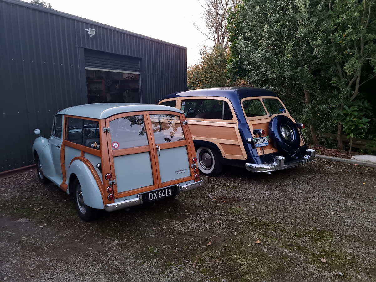
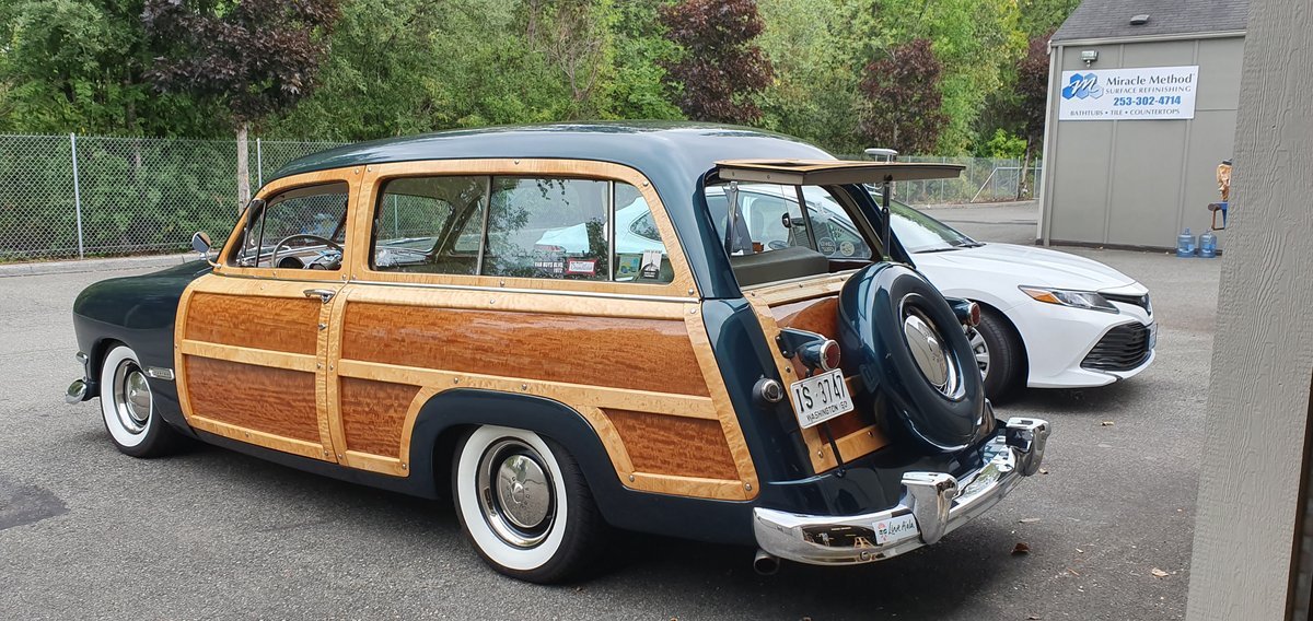
Picked up this other Woody for a parts car for the project, but might be too good to wreck?
1 point
-
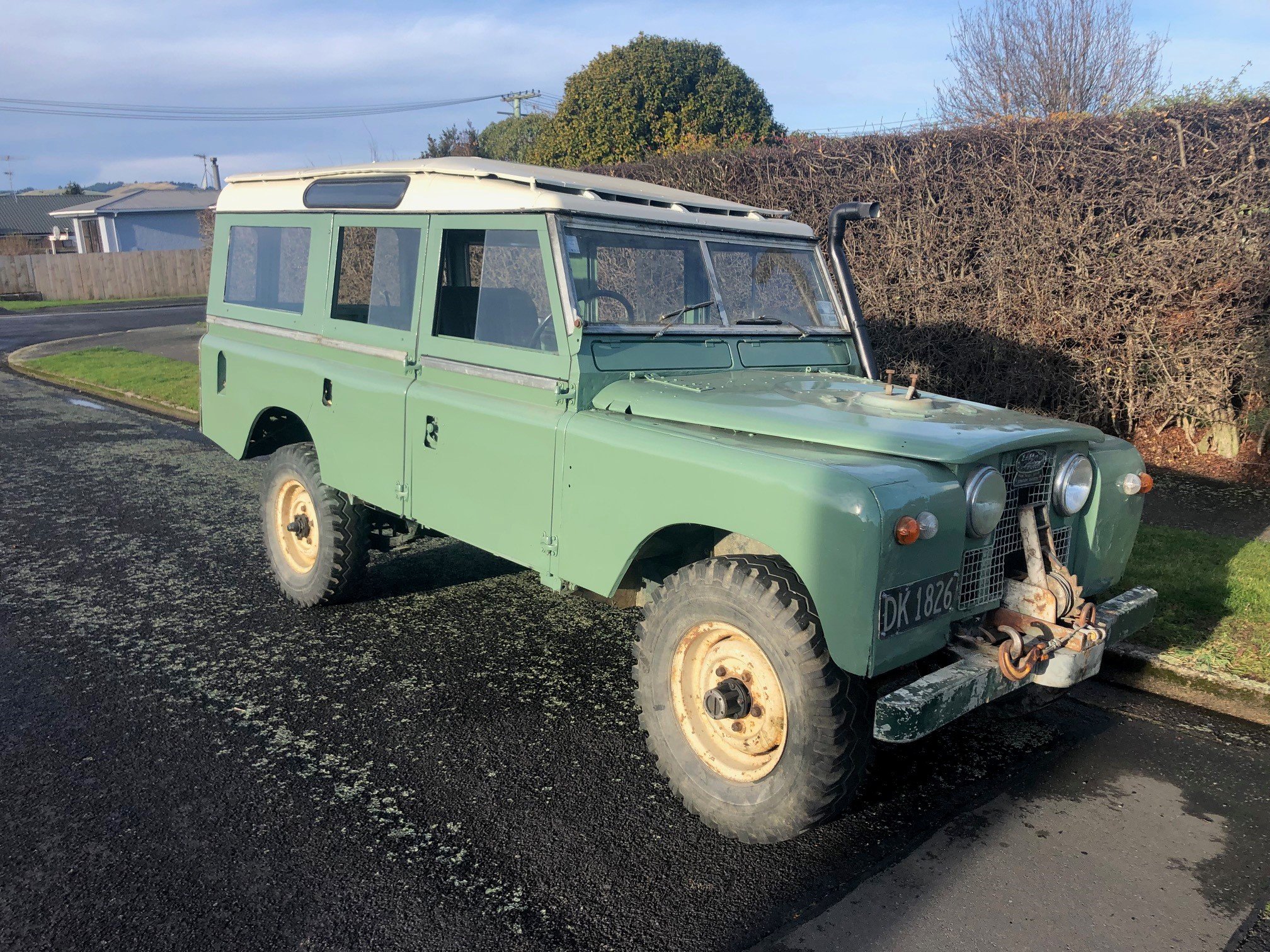
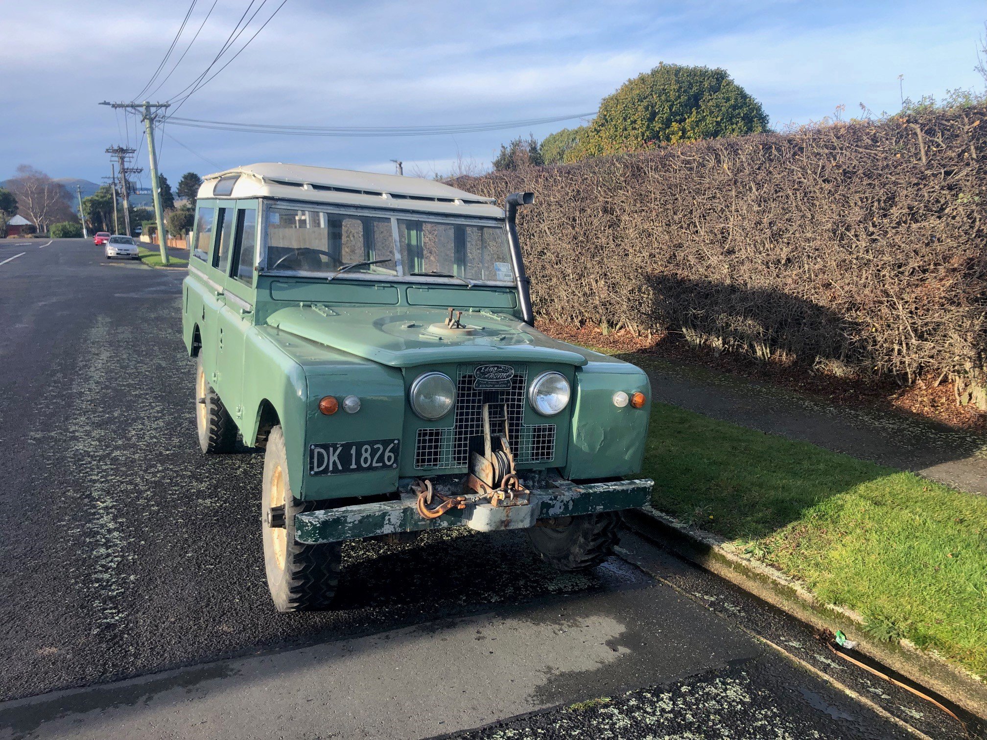
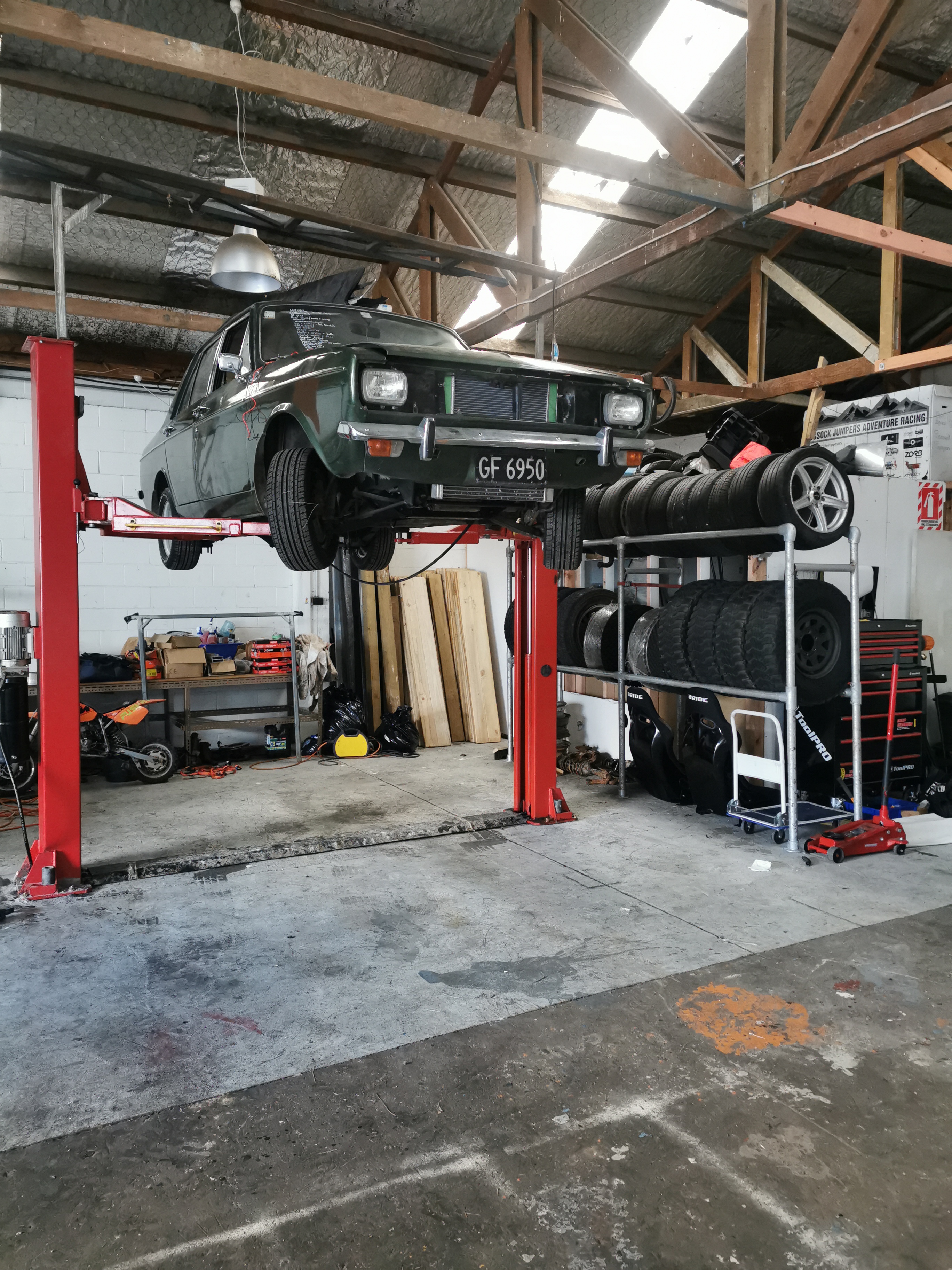
Hoist.... Engage Finally got the hoist up and running, built a tyre rack. Looked under the car, she is mint as under there, not a hint of rust.. 50 years of British oil leaks did its trick
1 point
-
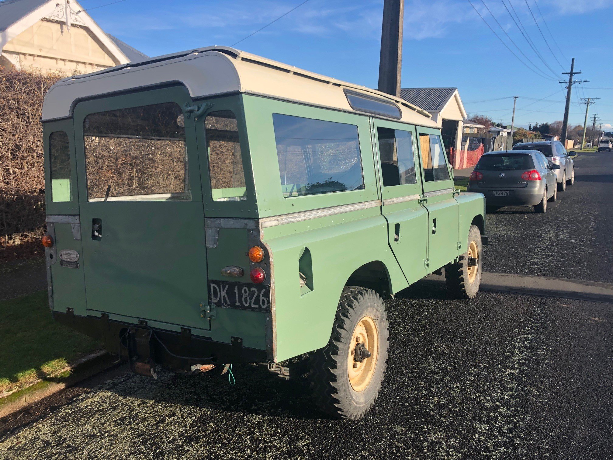
WOF passed, just a mention of a chip in the windscreen out of the drivers vision area, and the cracked fog light lens (which still passes because its not letting moisture in). Great success. Also got sick of the guard rub from the RH Rear, so jacked the rear of the car up and had a look. Found a clean spot on the inner lip where it had been rubbing, so took a small sledgehammer to the lip and hammered it in a bit. No more rubbing, so now I can drive the car harder, like it was built for. Next on the list is to replace the clock spring so I can fit my 3 spoke steering wheel, and replace and rekey the ignition barrel since the previous owner made a mess of it somehow.1 point
-
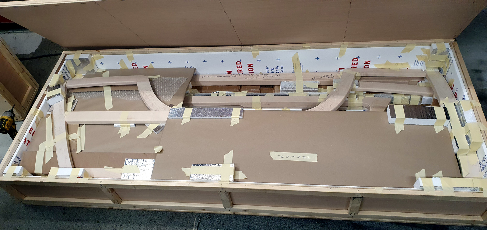
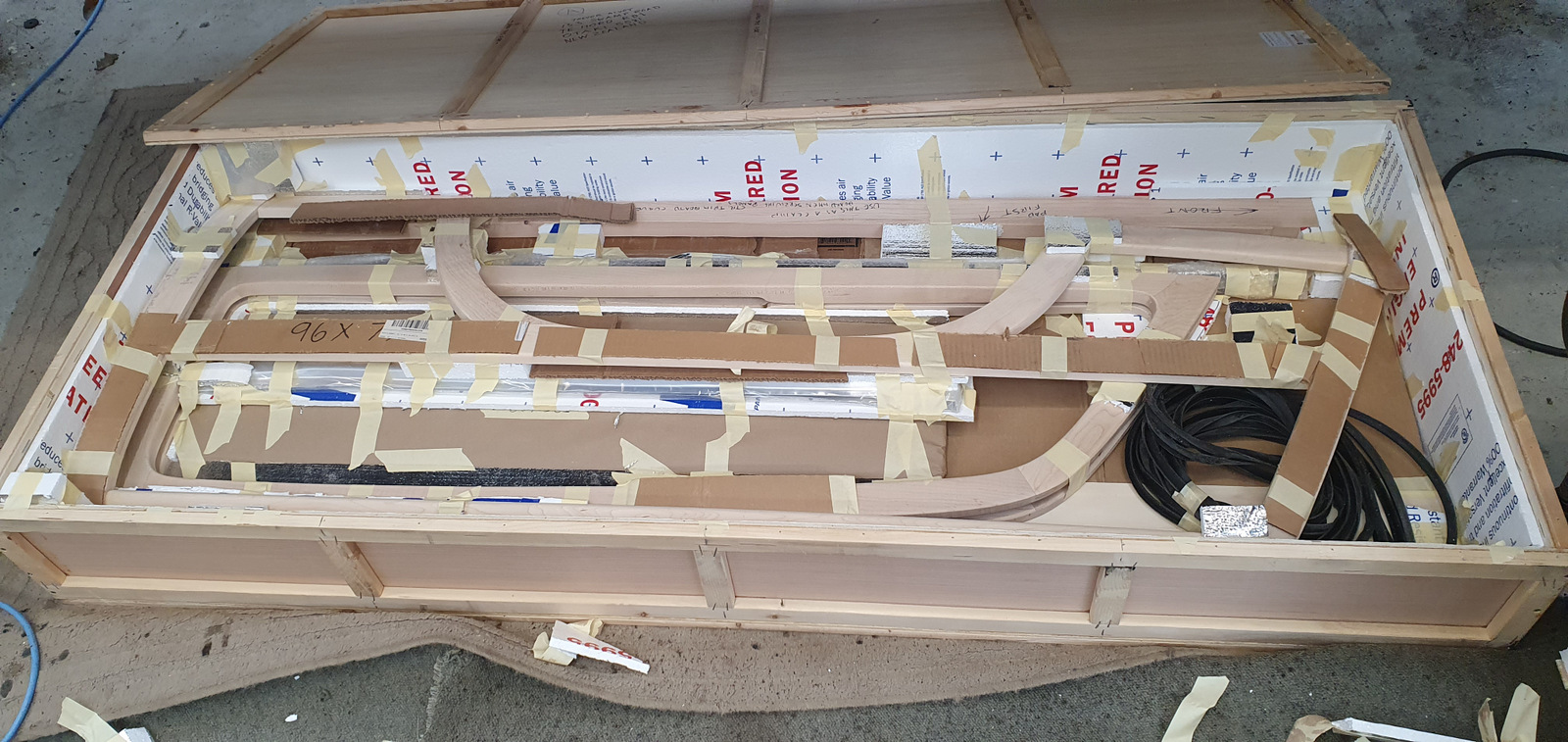
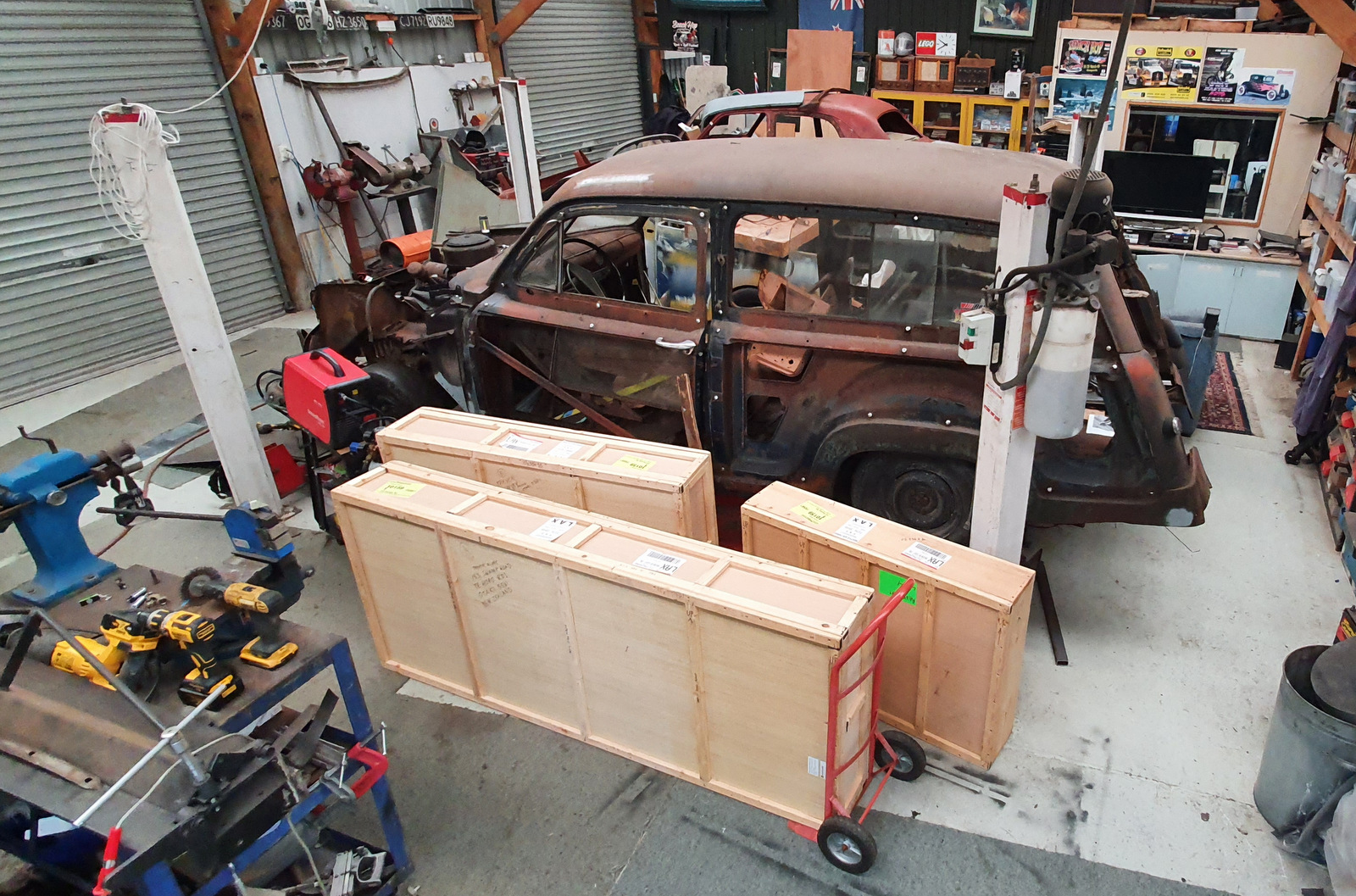
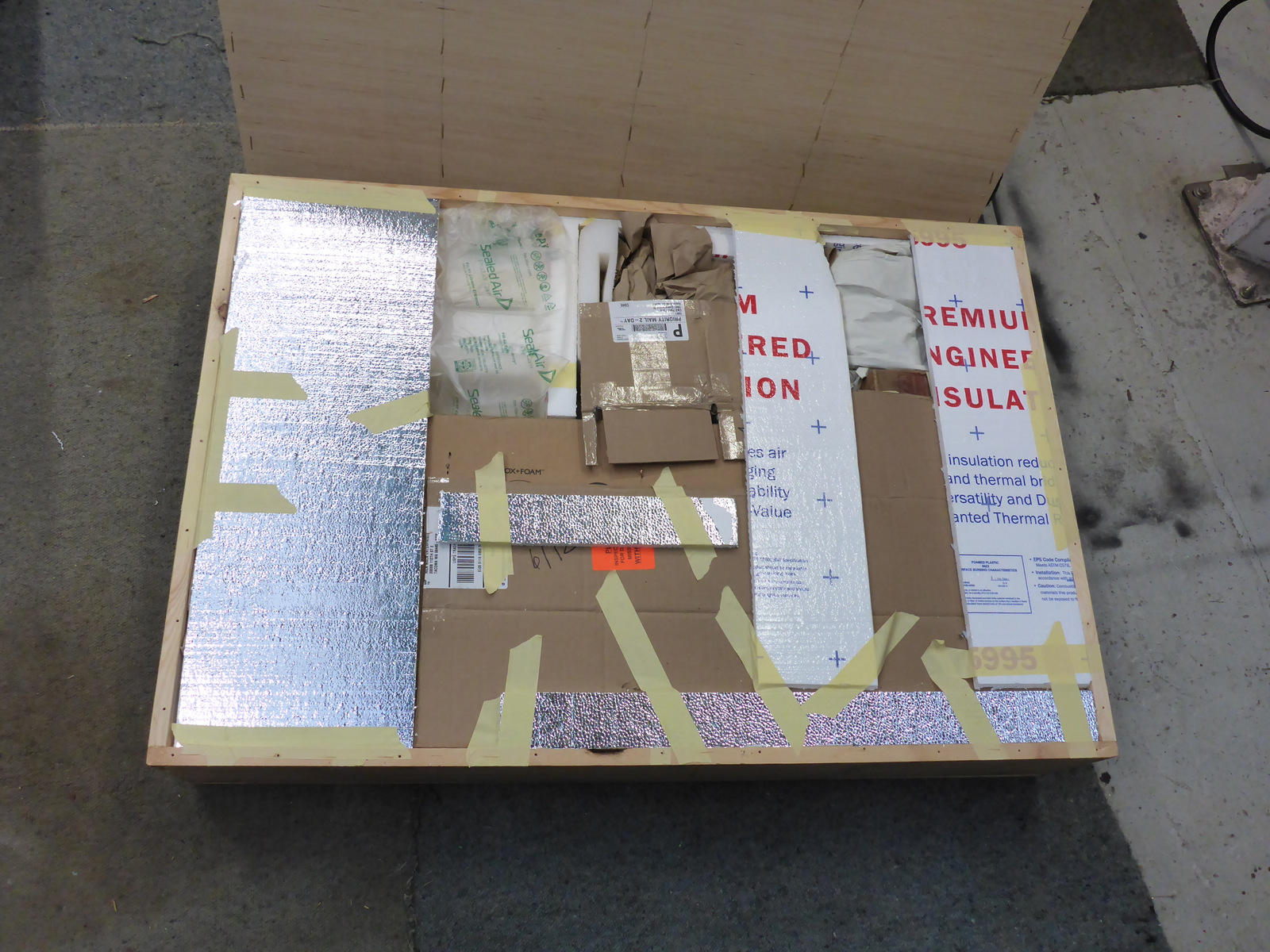
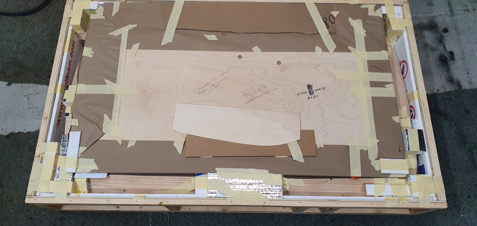
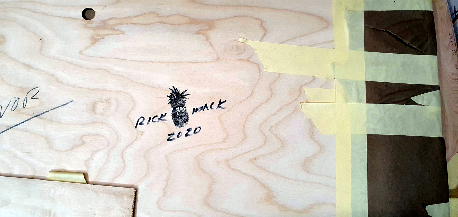
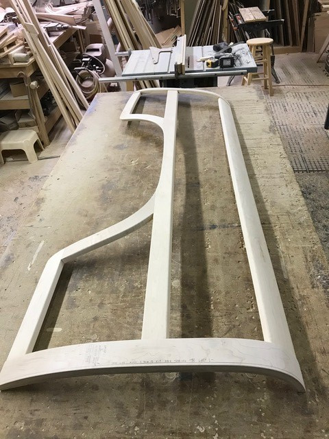
I eventually unpacked the whole lot because I didn't want to risk the masking tape becoming permanently stuck to the wood. A quick test-fit of one of the rear pieces but for now the wood is all back in the crates to protect it from the sun and damage while I work (or not) on the body issues. It's seriously nice stuff from Rick though.
1 point
-
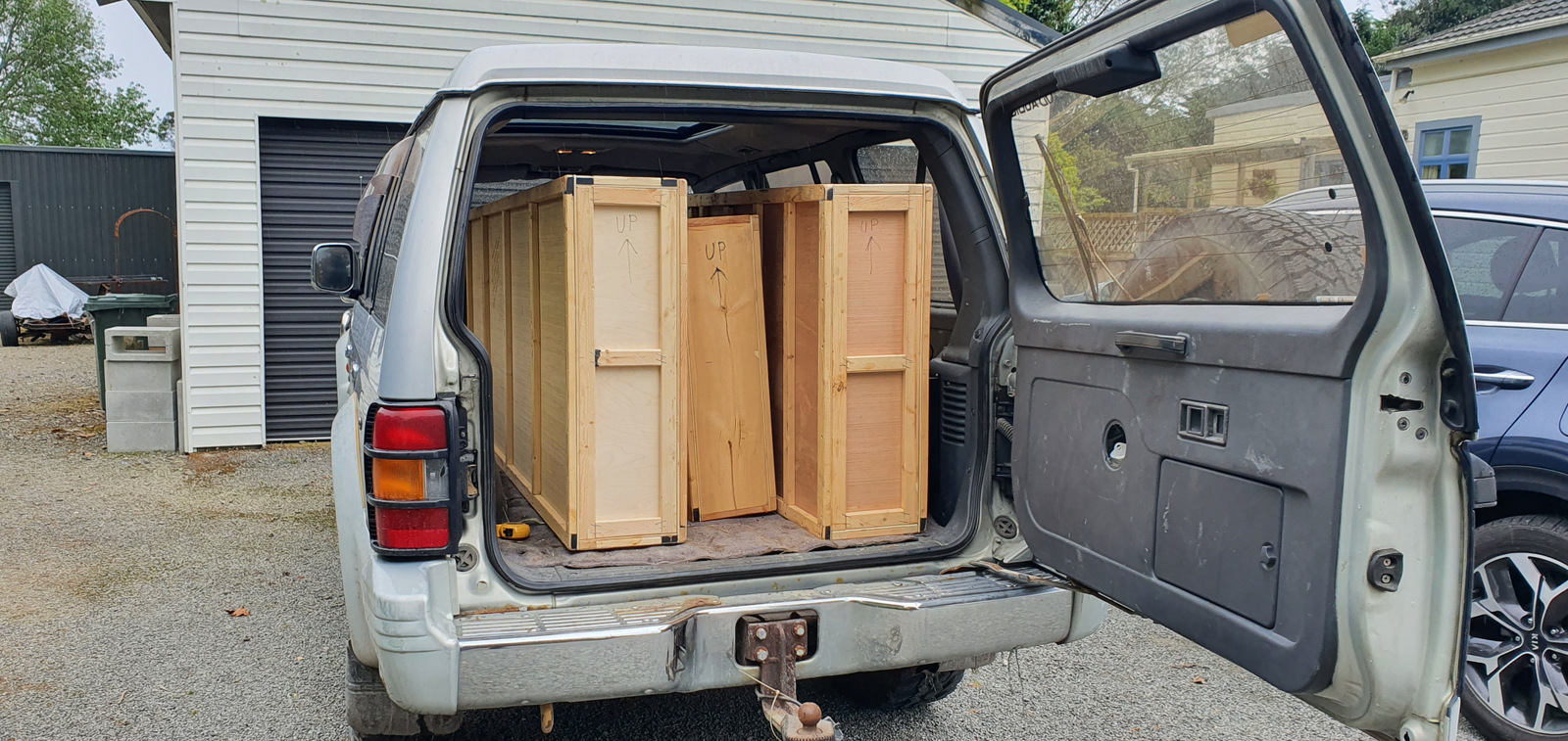
The crates left LA on 7 September 2020, but didn't arrive in Auckland until 30 September, then down to Wellington by mid-October where I had to pay the shipping and taxes (ouch) Just managed to squeeze them into the Poojero for the trip home. They were very well packed. The smallest crate was assorted parts the middle one had the door pieces, even signed
1 point
-
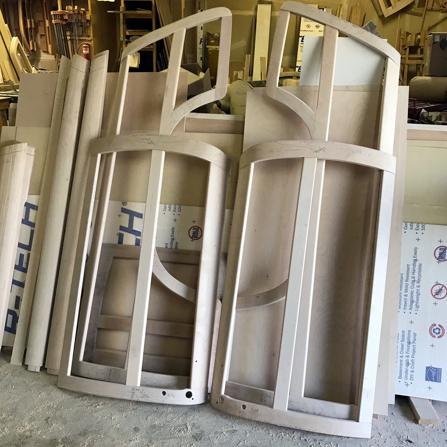
It was a long process, we confirmed the order in September 2019. The framing is maple and the insert plywood is mahogany veneer. Also included a full set of the interior panels also in mahogany ply. These pics are from April 2020 which was of course Covid Time. I'd also bought a few necessary parts from Rick, and others from Tom Fritz (https://www.ccrod.com/home.htm). Got some new repro sill plates from https://cgfordparts.com/. These parts were all shipped to Rick in Tacoma who crated them up for me along with the wood parts. I arranged the shipping with Mainfreight / Kiwi Shipping including the Tacoma WA to Garden CA leg. They left Tacoma on 22 July 2020.
1 point
-
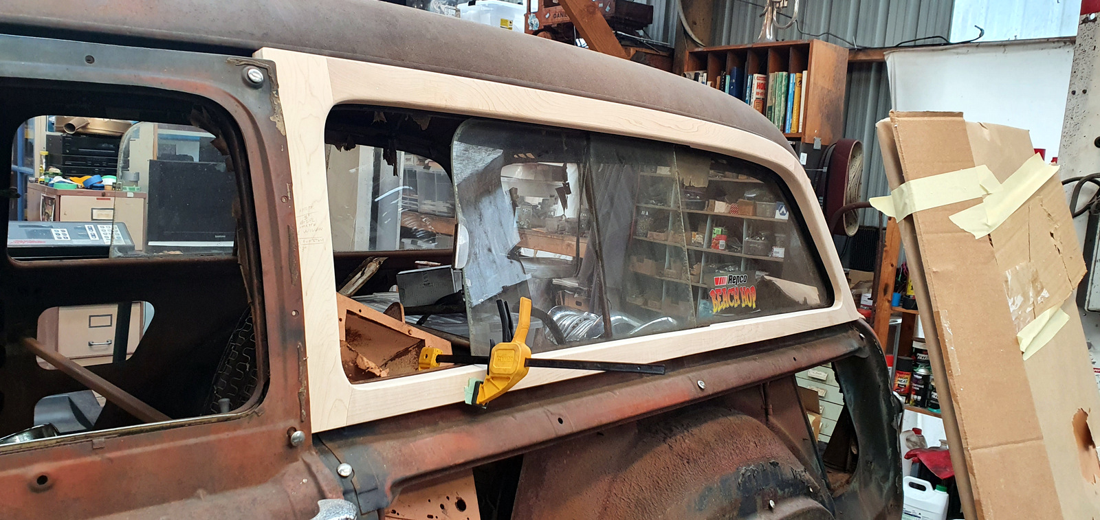
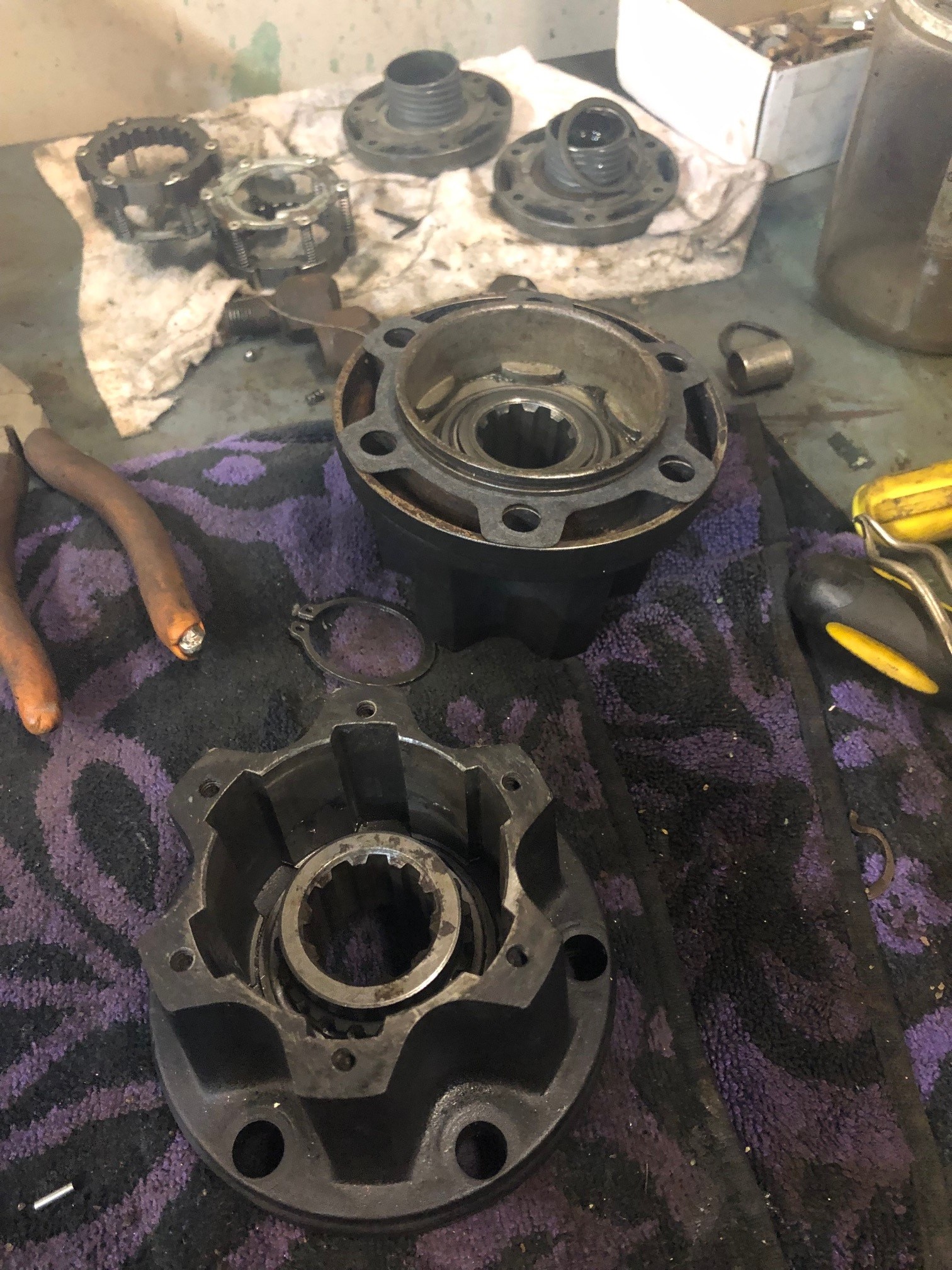
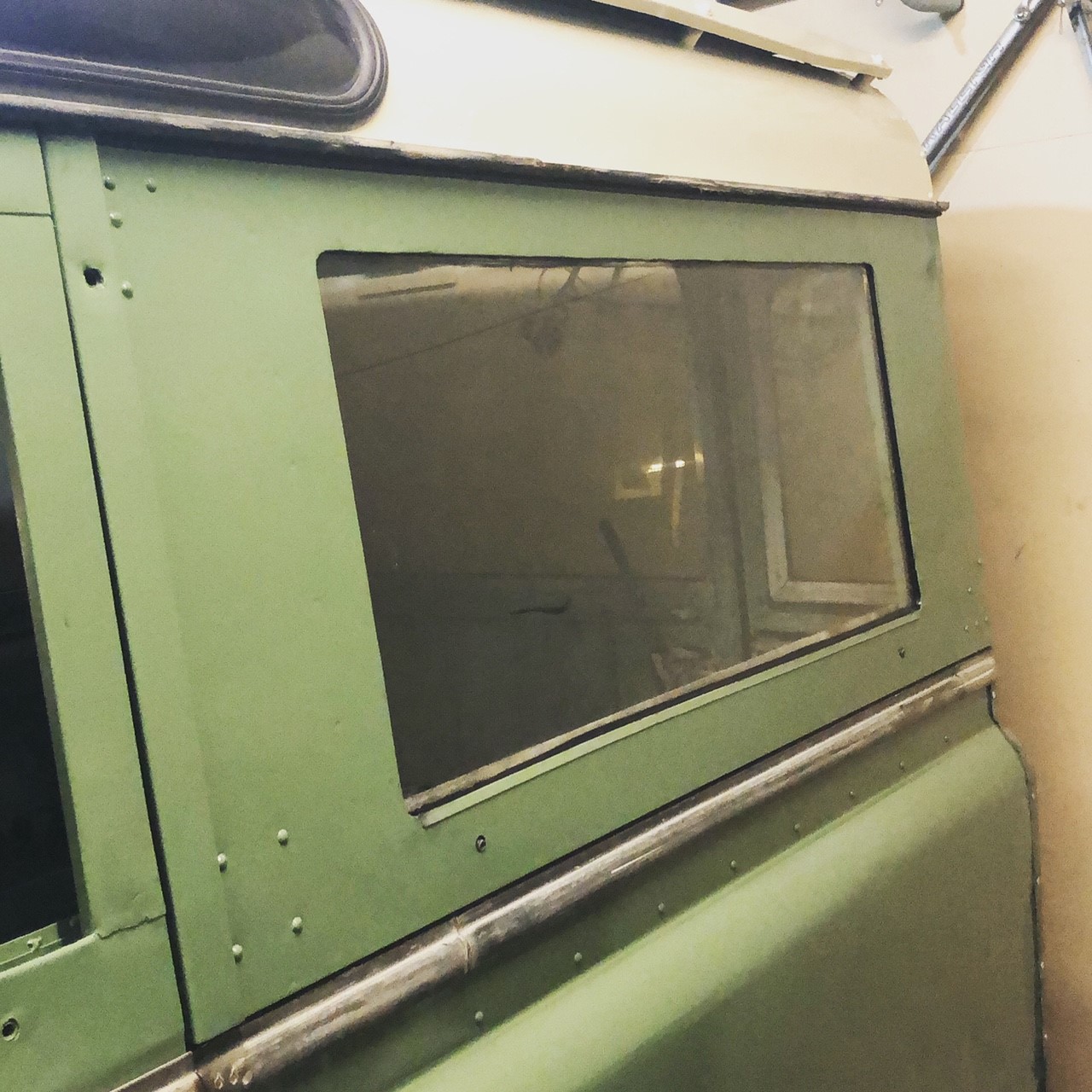
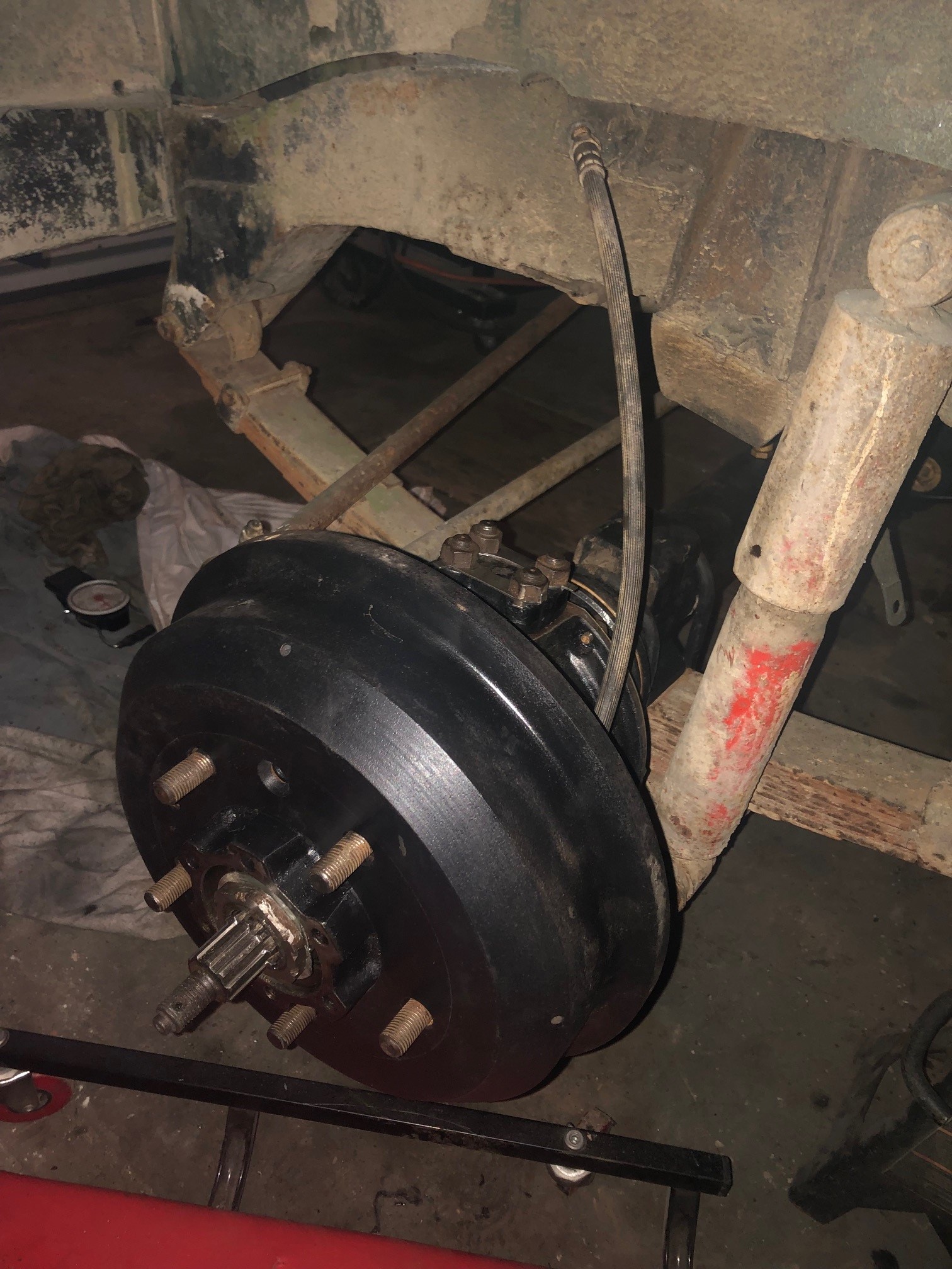
Continuing the process of reassembling this front axle Also giving these free wheeling hubs a bit of an overhaul. Think I mentioned I wanted to go to a fixed rear glass. I got some glass cut to the required size and bent up some simple brackets to drill into the frame, very much how the rear door glass is fixed. Pretty happy with the result TBH.
1 point
-
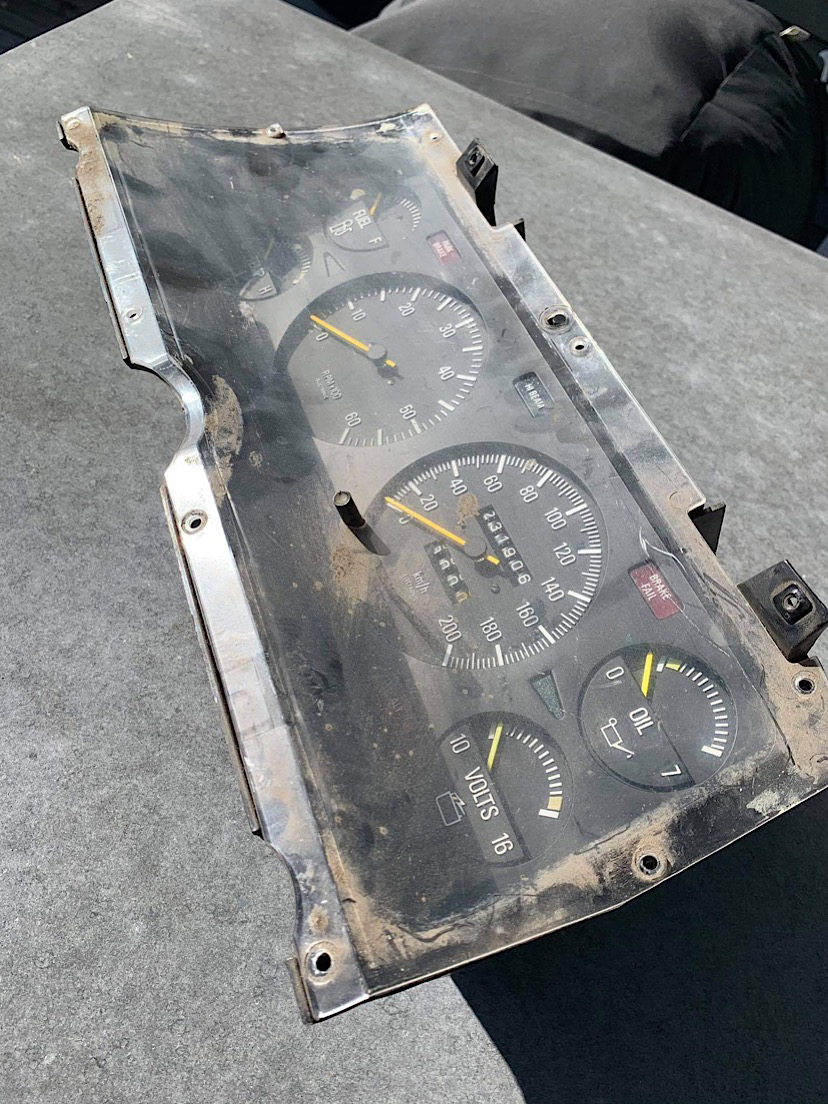
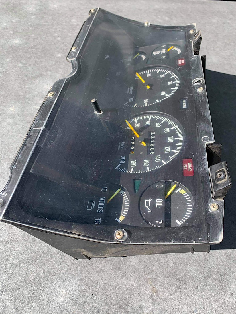
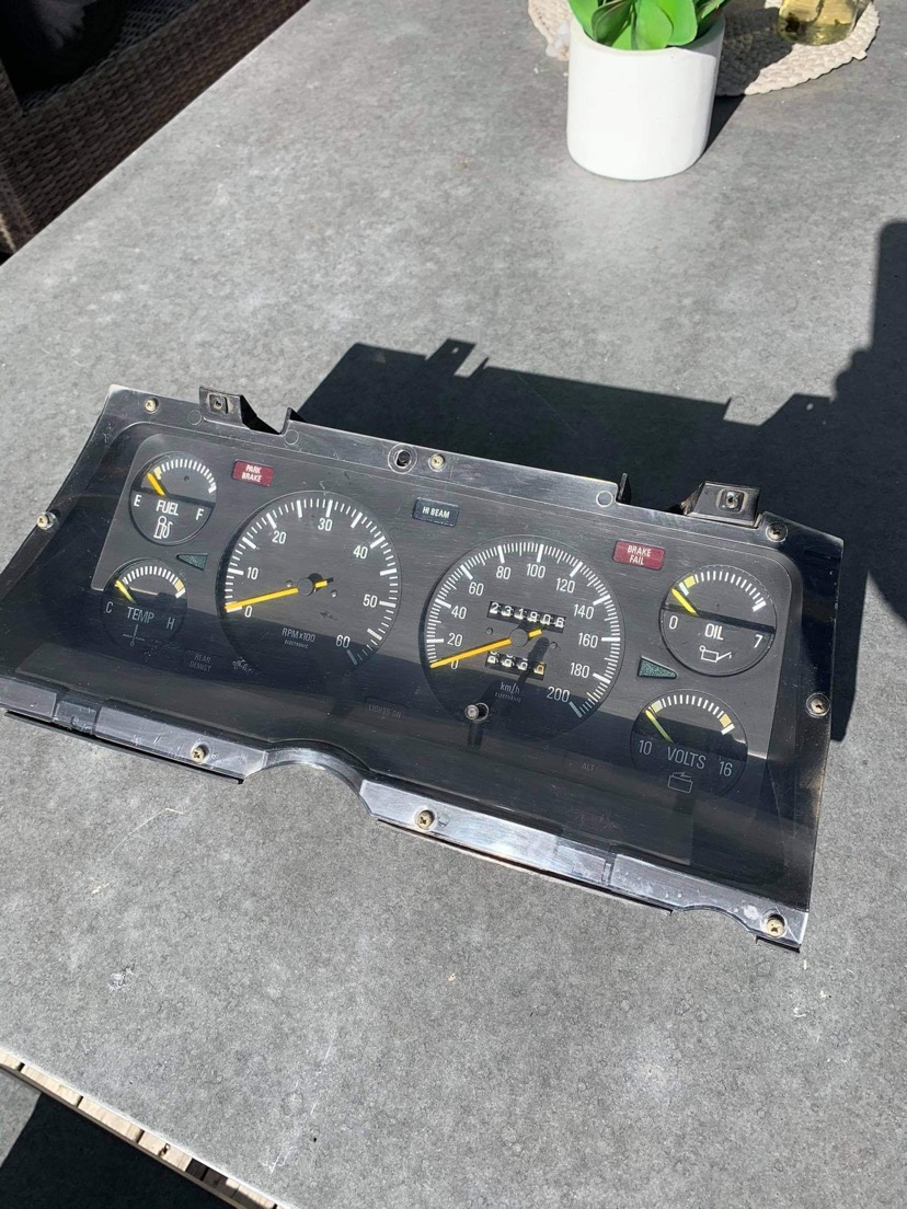
I also paid $50 for Fairmont Ghia speedo (usually $200 plus) as this has the rev counter where my povo pack Falcon only came with an “Econo Gauge” which appears to work on vacuum when you plant your foot and shows you how uneconomical your driving is. What a great invention that was I gave the speedo a but of a clean up too and it's ready to be put in.
1 point
-
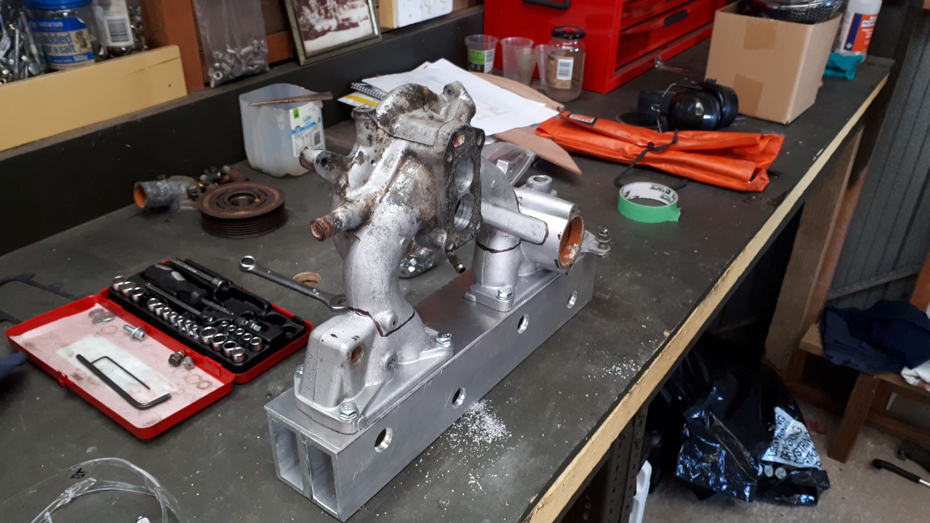
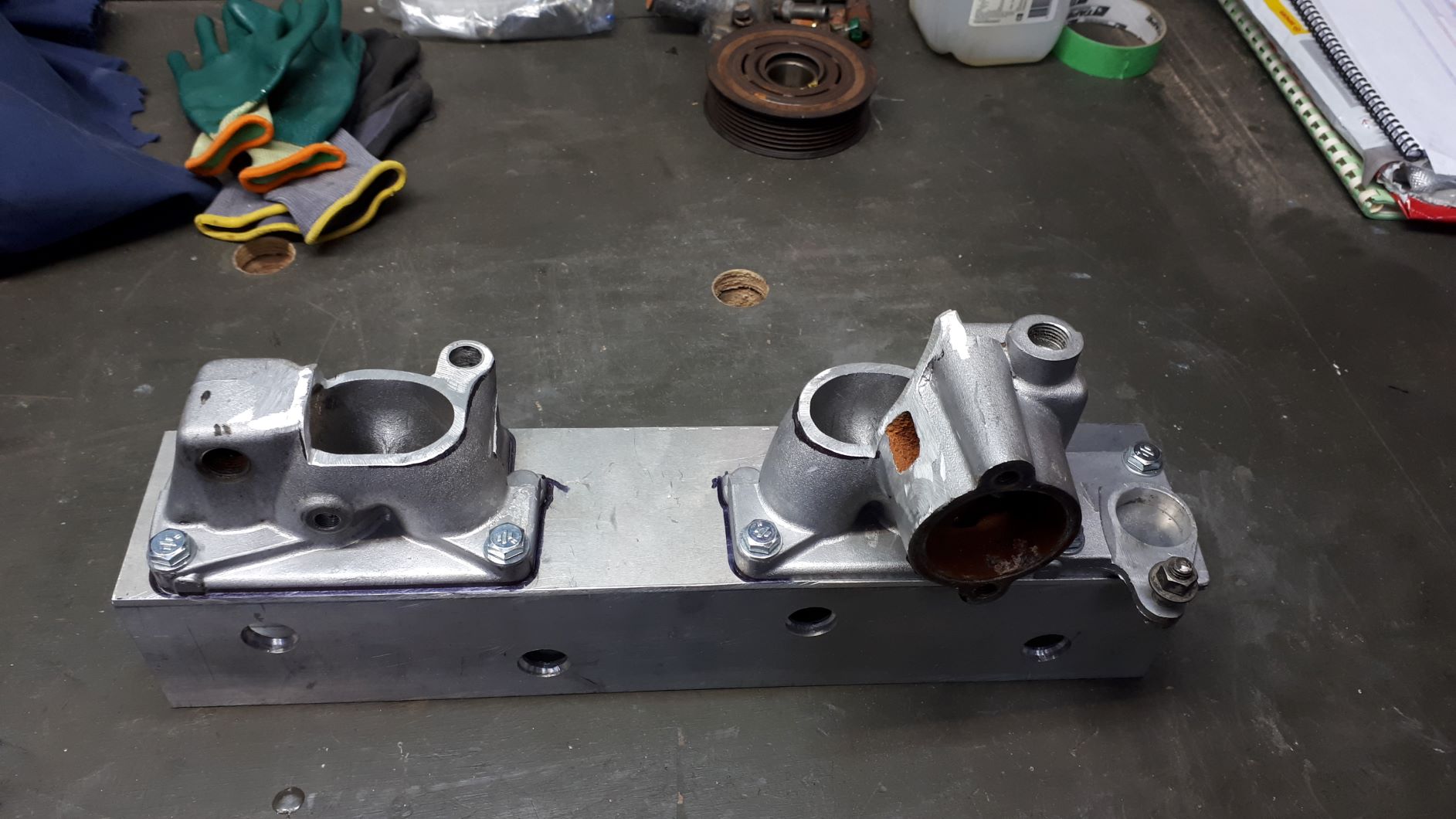
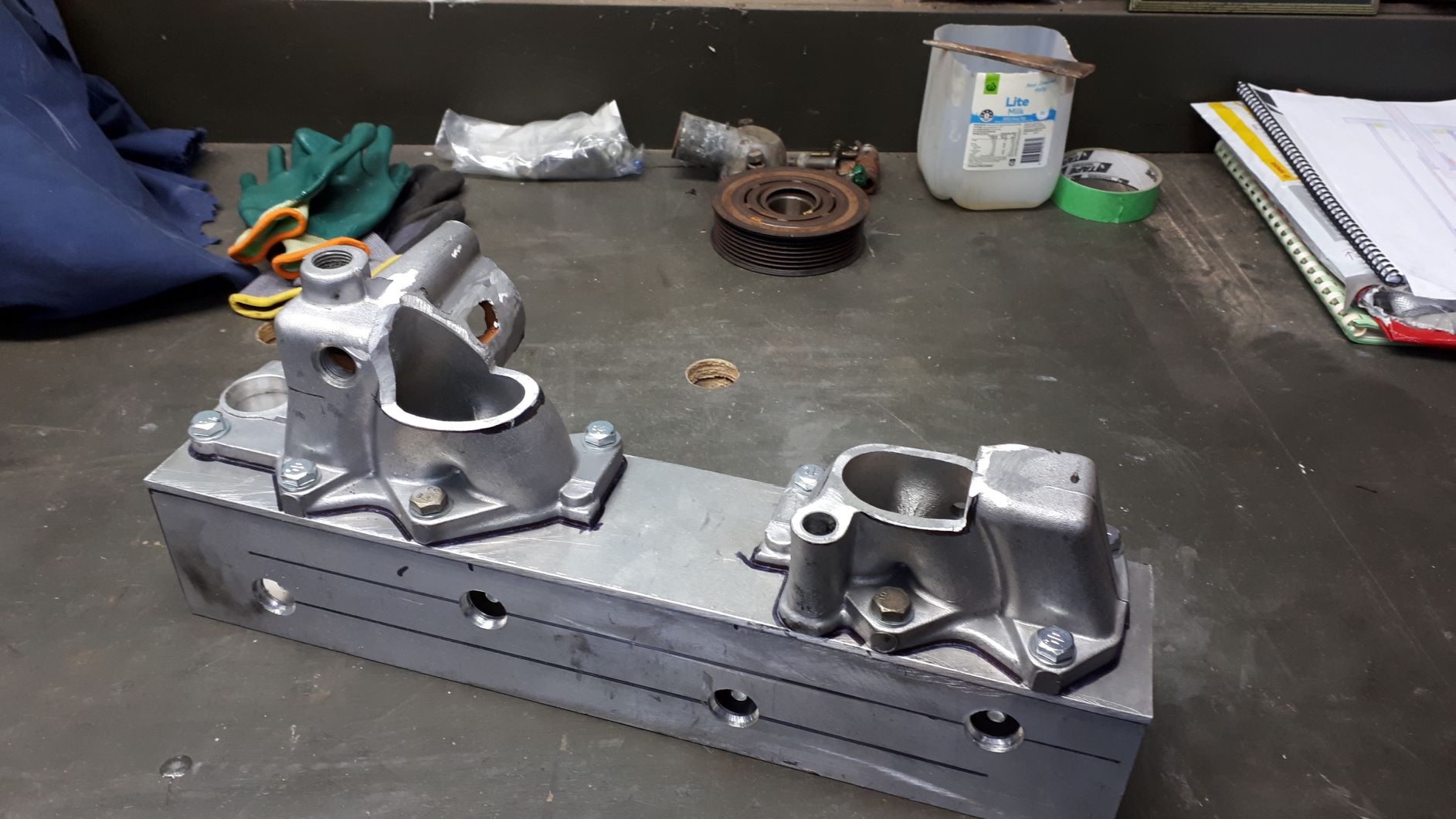
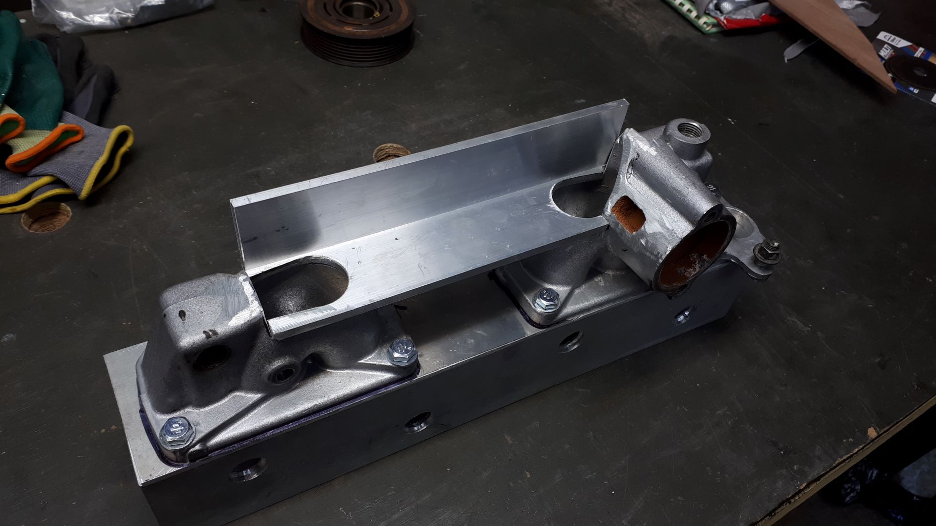
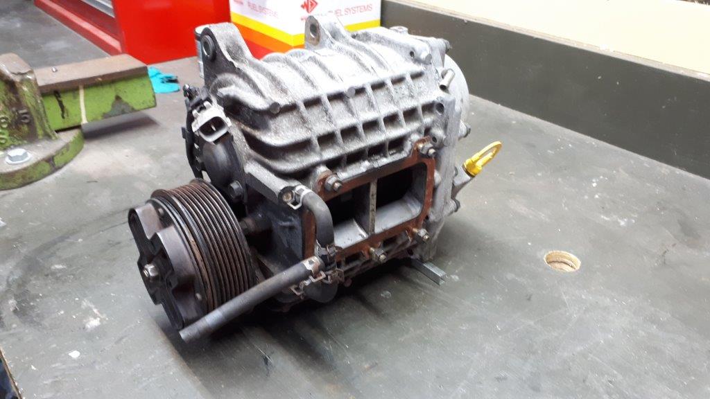
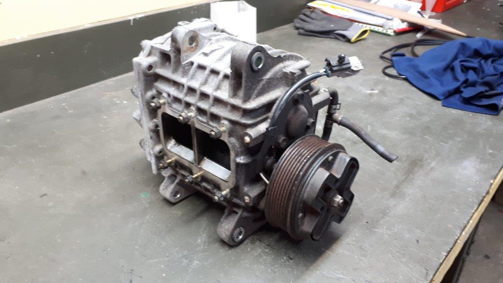
Big thanks to @MaxPower for helping out with a spare manifold from one of his vans. I checked online and for some reason you can buy a supercharger manifold for your Corvette or Mustang but there is no off the shelf option for your 1982 Mitsi Sigma. I will have to make one, what could possibly go wrong? I will post more pictures as the manifold comes together
1 point
-
The Sigma has been sitting around a bit. I drive it every so often but it's kind of underpowered compared with my Aussie 6 cylinder stuff and I really wish it wasn't. I have been toying with the idea of repowering it but I thought I might try to liven up the stock engine first. A buddy of mine dropped this off over the weekend. I really have no idea what I am doing but that has never stopped me in the past. What could possibly go wrong?
1 point
-
Here you go @MaxPower The front springs were just a little loose with the car jacked so I made them secure the oldschool way with some locking wire.
1 point
-
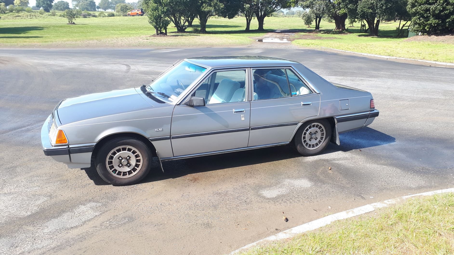
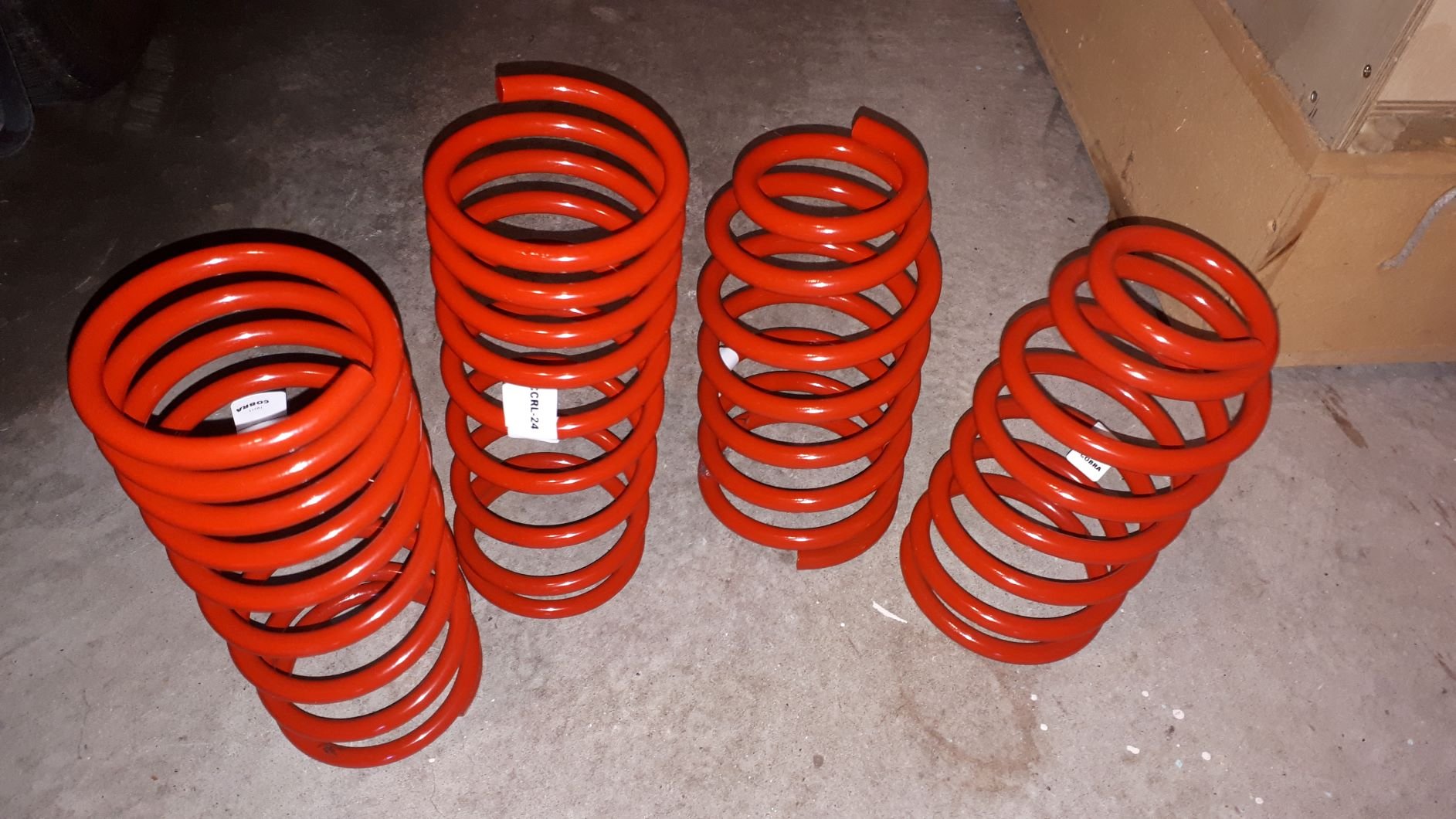
In the 1980's car manufacturers seemed to think it was a good idea to supply their customers with unnecessary and unsightly additional ride height. Last weeks project was to correct this with new springs and shocks all round. The car didn't drive particularly well so I did a back yard wheel alignment with string and a tape measure. I found that the front wheels were actually toed out so I also corrected that problem and it drives heaps better now. I will get it in for a proper wheel alignment sometime soon.
1 point


.thumb.jpeg.e0a4bff61111e0c8c7396950fcc94da1.jpeg)


This leaderboard is set to Auckland/GMT+12:00