
Leaderboard


Popular Content
Showing content with the highest reputation on 05/28/22 in all areas
-
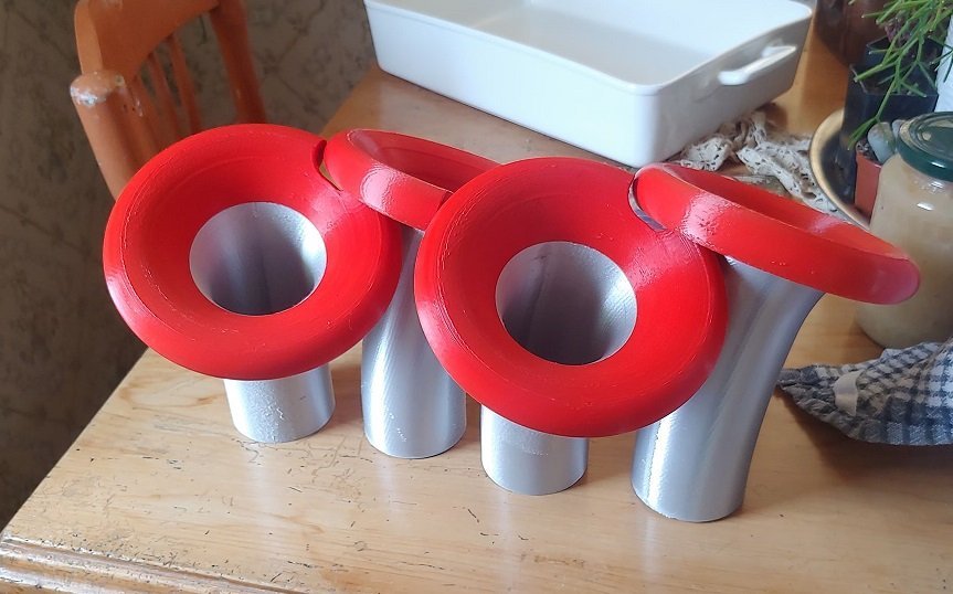
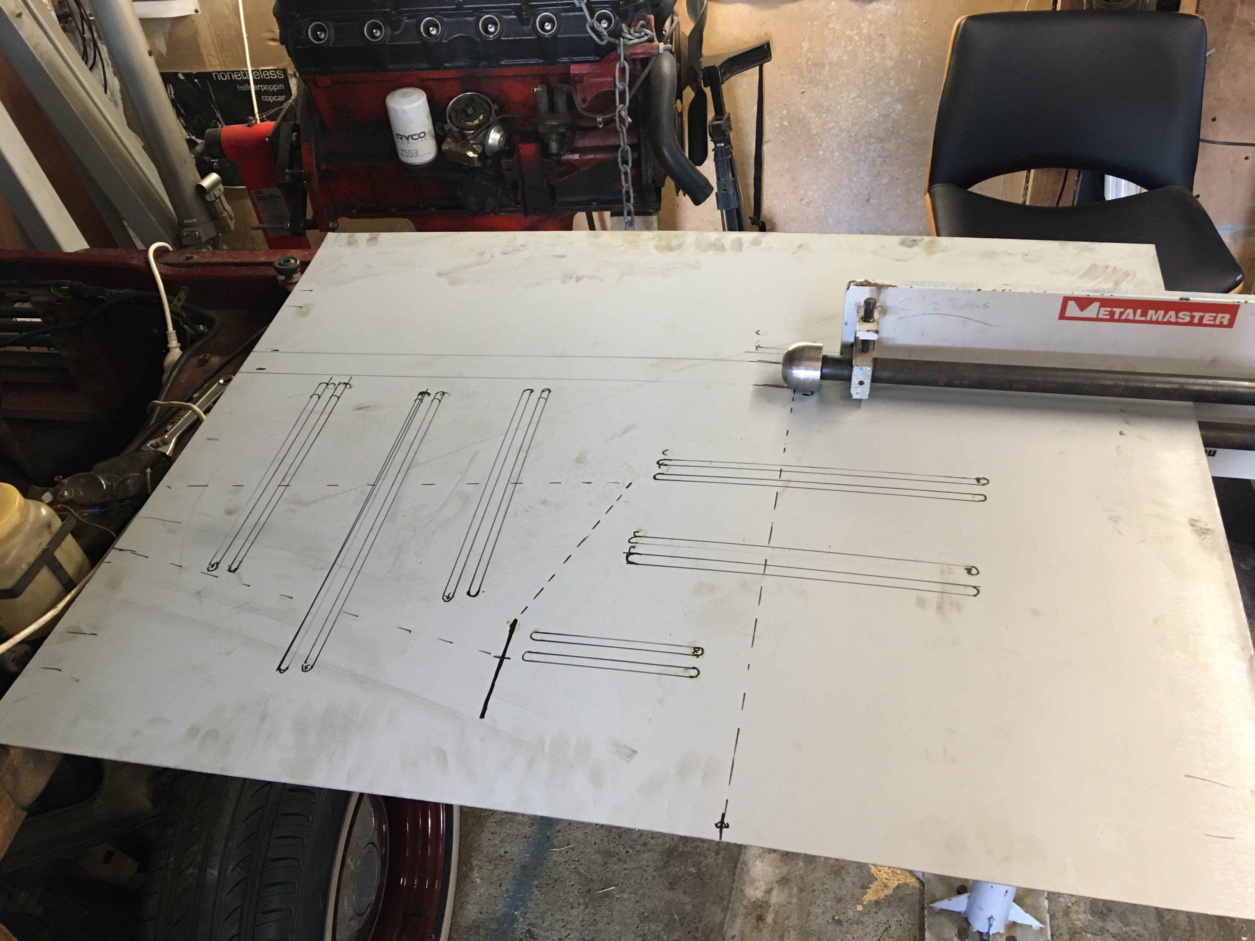
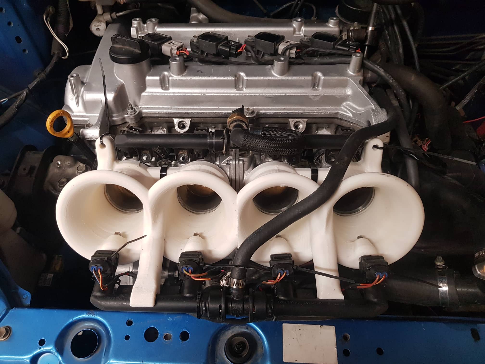
Hello! Thanks for the post. Over time ive seen more and more and more of my calcuations and expectations etc unravelling when compared to real life testing. One really interesting thing regarding tuned lengths, which is covered in the video below a bit. I designed some trumpets which had a theoretically ideal bellmouth on them, but, these are too big to fit side by side. So I added a little bit of a curve to stagger them like this. So these didnt actually work out amazingly great, in fact, they were pretty much equalled or beaten by a set of poorly fitting peach cans jammed on the intake. (?!) The interesting part though, was that since I had such a large graduating elliptical shape to the bellmouth. The tuned point at which the wave reflects seemed to be somewhere deeper inside the shape. Not right at the outer end. So they behaved like a much shorter runner than their geometry would suggest. So if I'm using some calculator to tell me how long to make my runners, is this calculator complex enough to take into account how elliptical the entrance is? If not, then its going to spit out the wrong information right from the start. So then you need to do some testing anyway. So why not just do testing anyway? Another issue is that this motor has the crank offset by 14mm towards the intake side, in the block. So the accelleration rate of the piston going down, is different to the piston going up. So the maths for working out peak accel becomes more complex than if it were centered. So without taking this into account, calcs would be wrong again. Also on my previous intake setup, the intake runners had a 90 degree bend in them. If I am working out the tuned length, is this the shortest inside length? Centerline length? Or outside length? How does the speed of sound travel around a bend like this? More brain bending and more complexity to add to a model. Since we're not talking about something deeply theoretical like aligning a space telescope, and empirical testing of different lengths is incredibly easy. Especially in the era of 3d printing. These days I will always prefer to just do some work and test some iterations rather than rely on calculations which cant possibly capture the real life complexities involved. Does the speed of sound travel faster along the inside edge of a curved runner? Honestly I have no idea. But I can make curved runners and see how well they work (or not) It's like, using VVTI to adjust the cam angle. I dont care about, nor can I accurately calculate, all of the theoretical interactions that result in XYZ cam angle giving the best power. But I can move a cam to a particular position, and see that it makes good power. So thats where the cam timing goes. Sounds like a bit of a pea brained approach, but it's actually acknowledging and making peace with how insanely complex all of the contributing variables are. It's nice to delve into some theory but it's just too damn complex to accurately calculate. I think you will find it fascinating to watch basically every single video on the Garage 4AGE youtube channel, hosted by our very own @kpr. It's all amazing stuff, and seeing some real life iterative testing has absolutely crapped all over a lot of my previous expectations. A lot of things that I previously thought would matter a lot, just simply dont. In this video below, he iteratively tests a whole big bloody stack of inlet lengths and shows all of the dyno plots. This might be an interesting data set for your calculator. It's also interesting how much power his 1600cc makes with some incredibly long runners, much longer than most people ever use.
 13 points
 -
We’re on schedule, couple more bits tomorrow and some hand-held blasting to merge in the repairs/ take the shine off grinds then I’m calling it. First time I’ve had all the wheels on it, Shame it’s got no panels hung! Looking pretty clean but there’s still cuntloads of sand11 points
-
All sort of back together last night so took it out for a cheeky driver. Rear master was too big with a .75 so wasn’t getting too much braking on the front. Swapped out to a .7 in the rear this morning and it’s much better now- wants to launch you through the front windscreen. Speedo works well with my fancy little box. Just need to set it up for VSS input only. No major leaks found so far, looks like a little weep from the front of the sump to will re torque those bolts. Bit of a weapon compared to the old 1500!
10 points
-
8 points
-
didn’t find any goodies at the swapmeat today but that’s ok..7 points
-
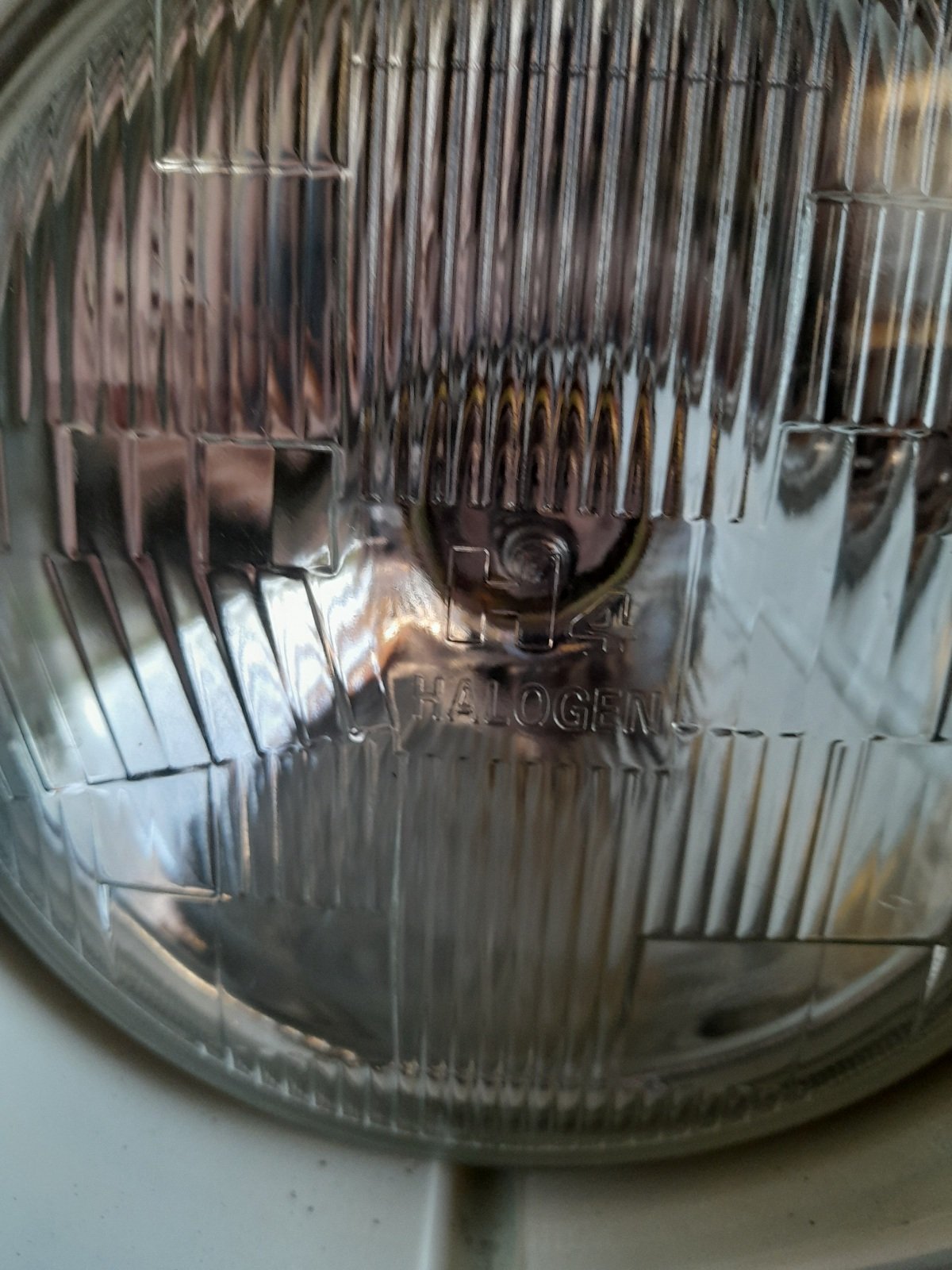
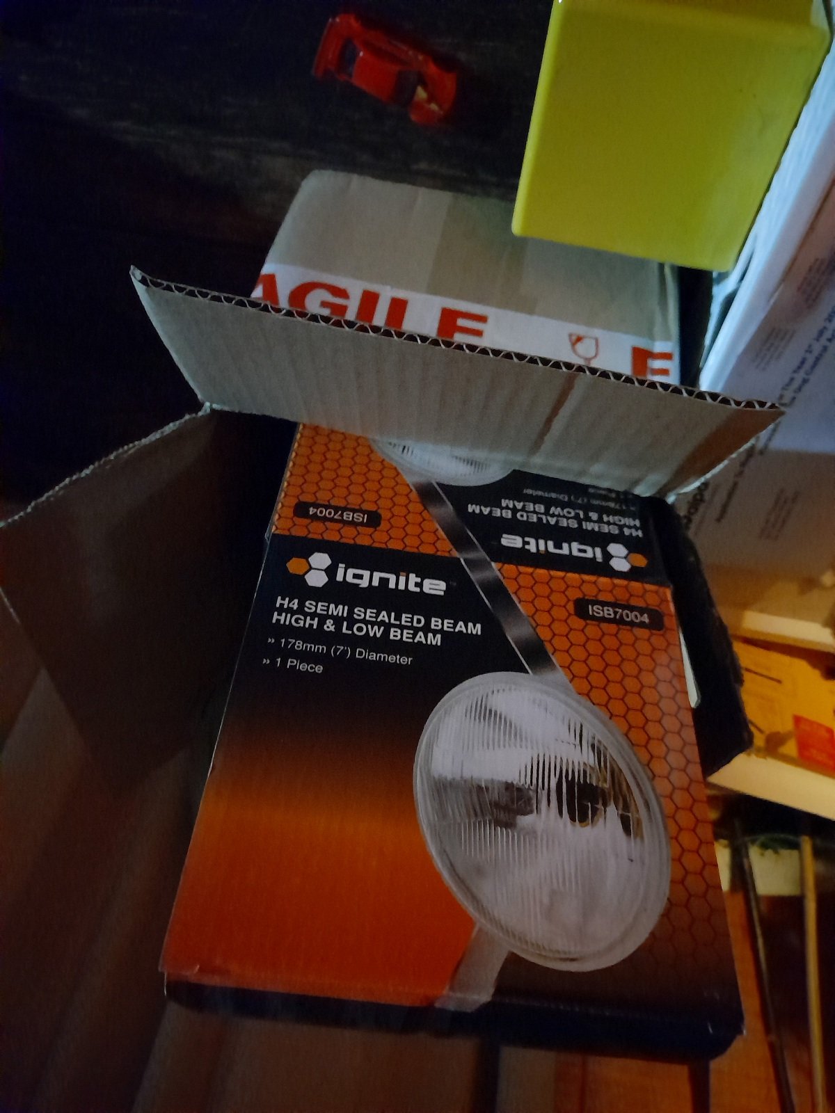
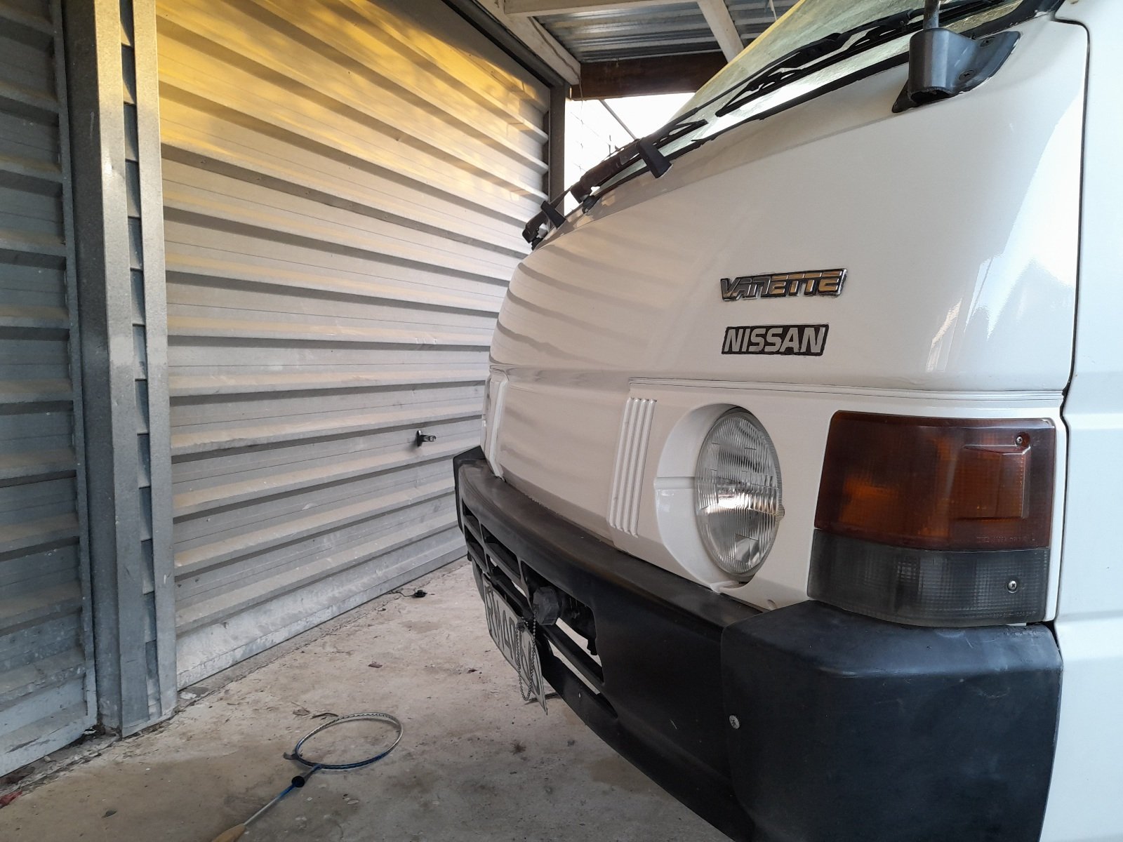
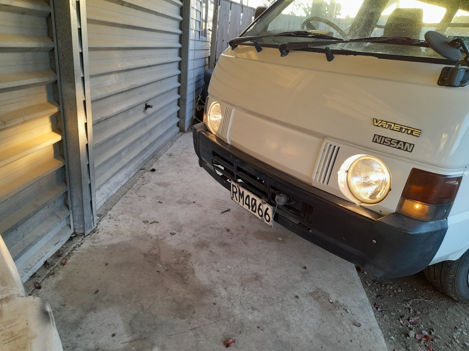
Converted the blown sealed lights to h4, replacable bulbs, got these ignite ones for $100 or so with bulbs, pretty good deal really, they work fine, and that almost sums up everything i need to do before cert... Want to do some test driving and long distance drives to test everything is reliable... If anyone has a h190 diff head lying around that i can weld, or knows what lsd centers are able to fit in casing... let me know, having a hard time finding anything ...
7 points
-
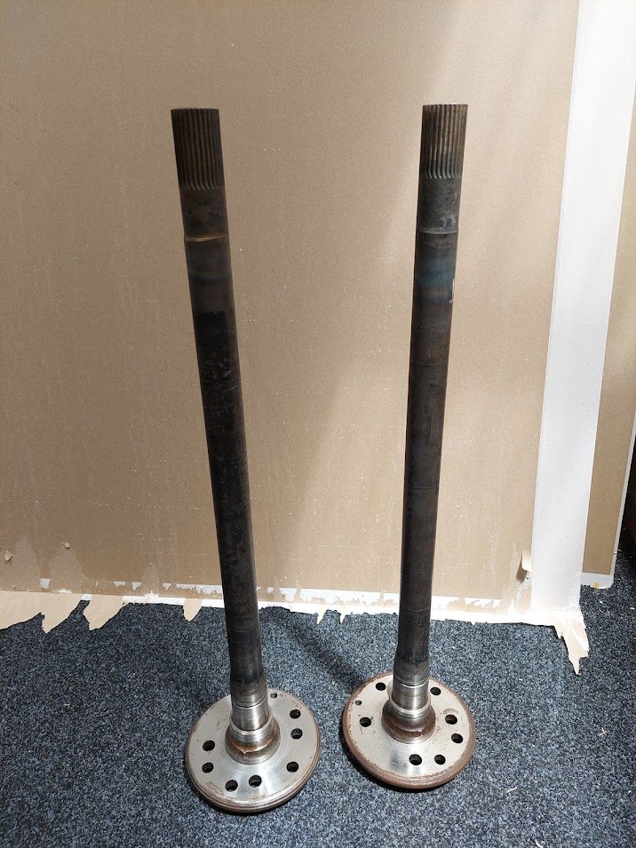
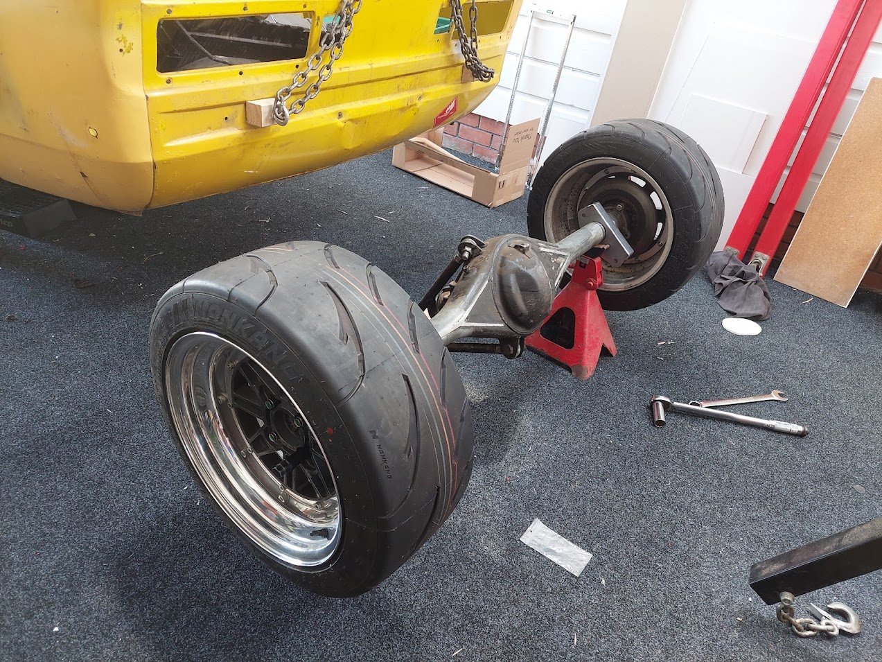
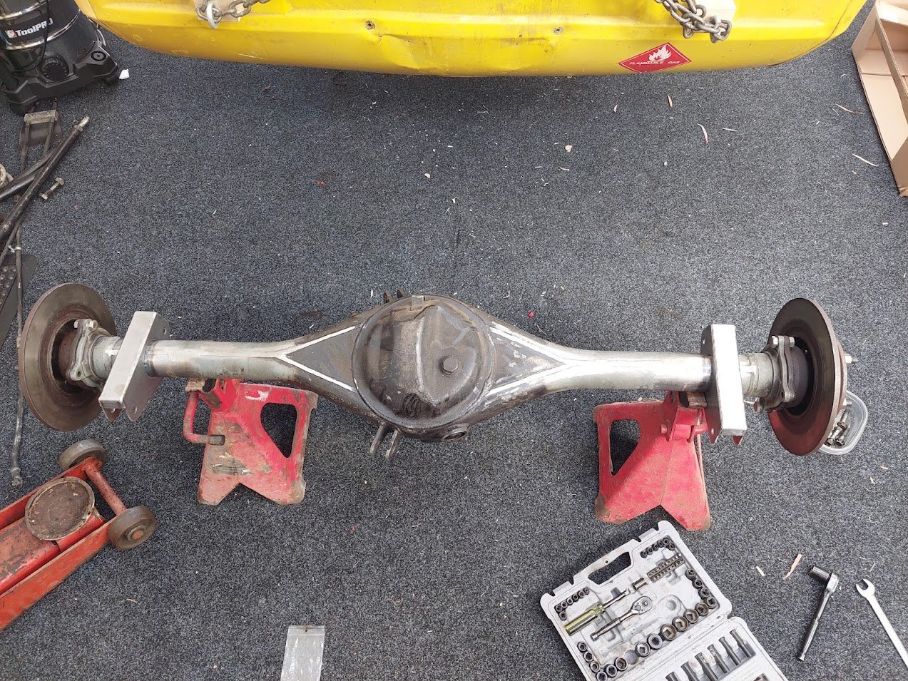
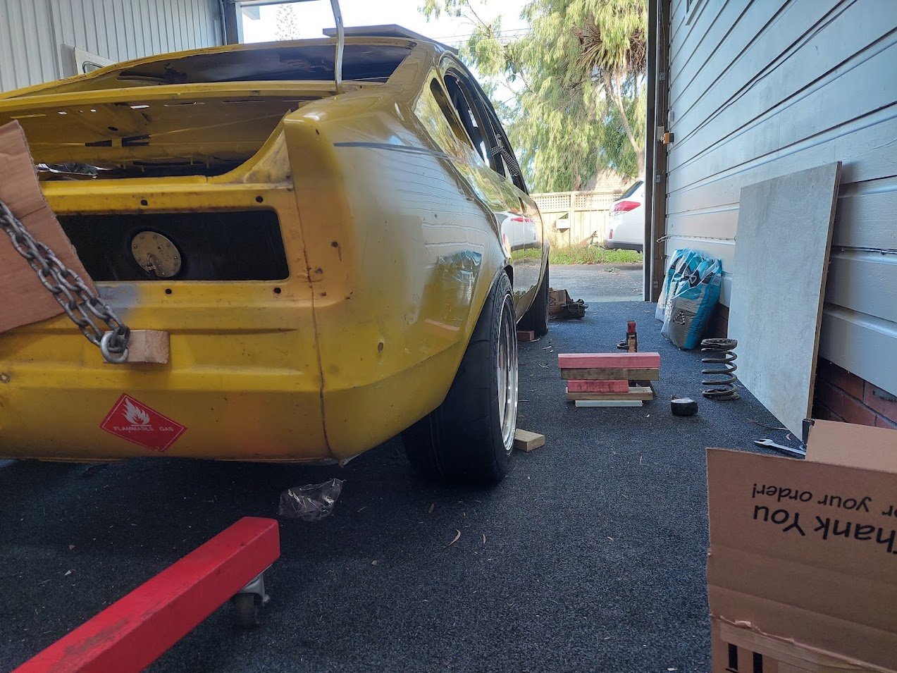
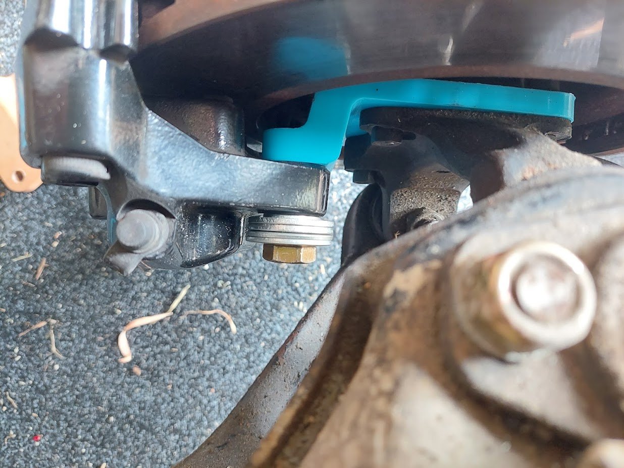
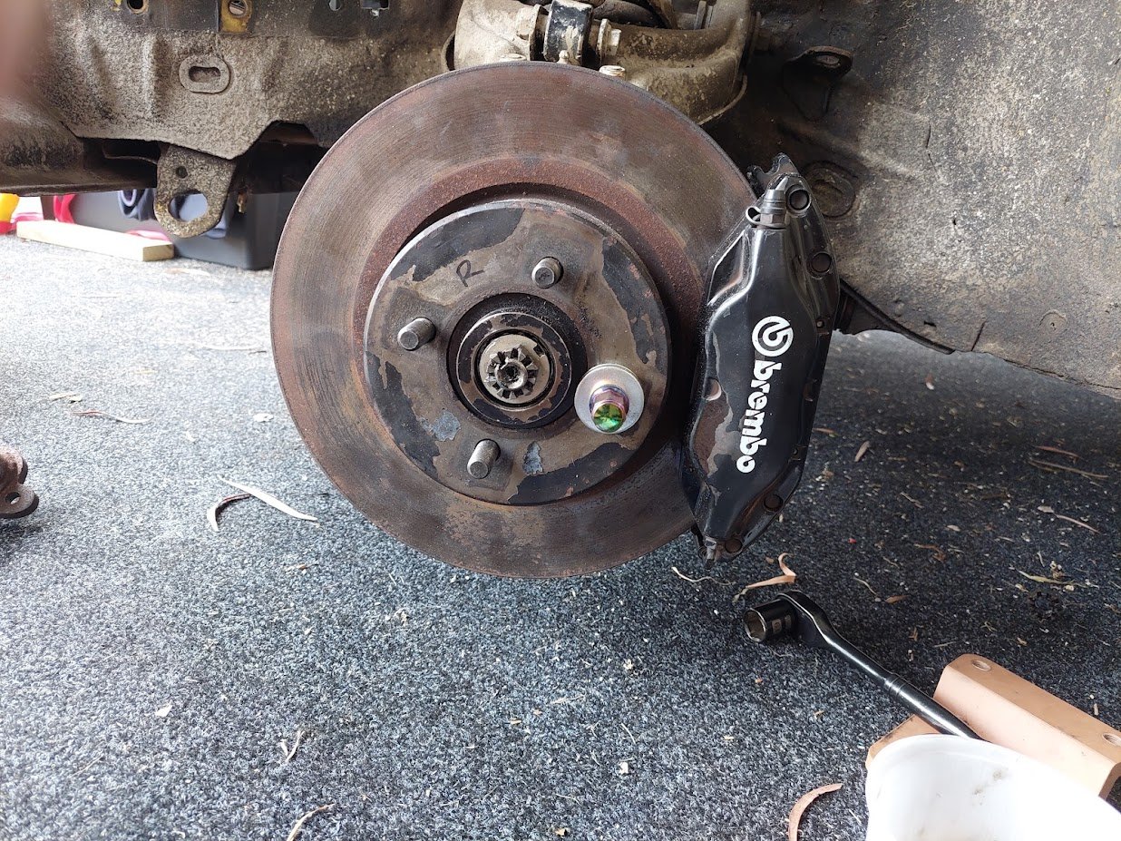
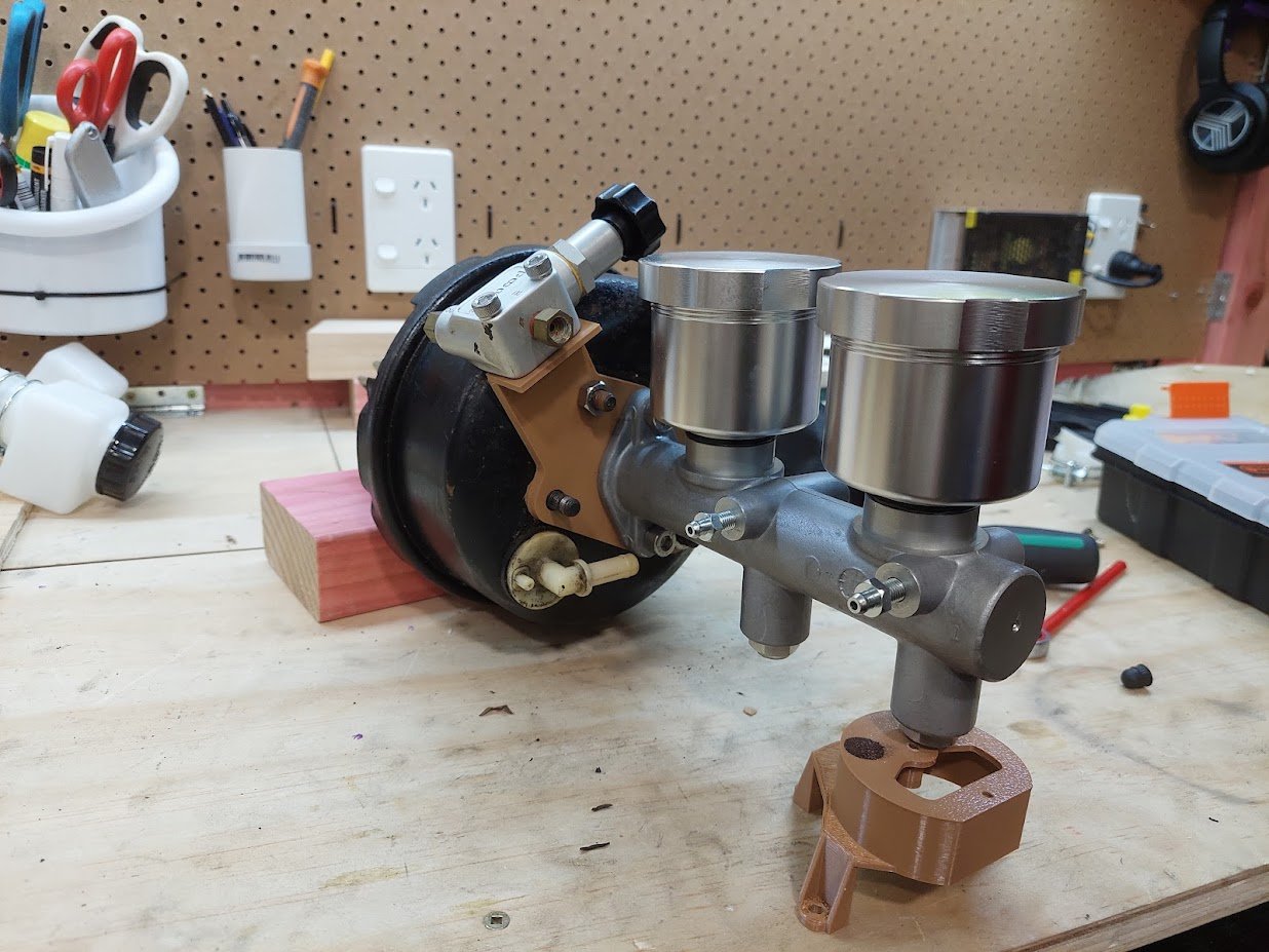
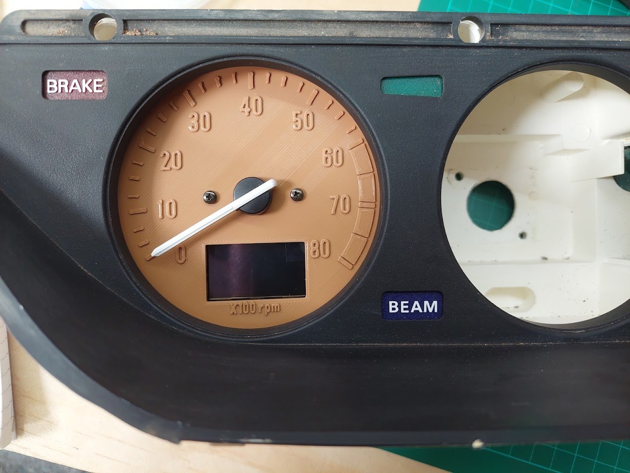
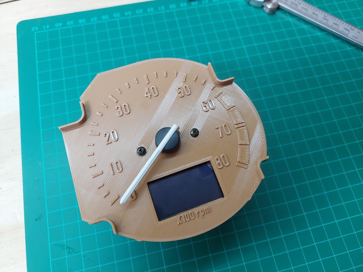
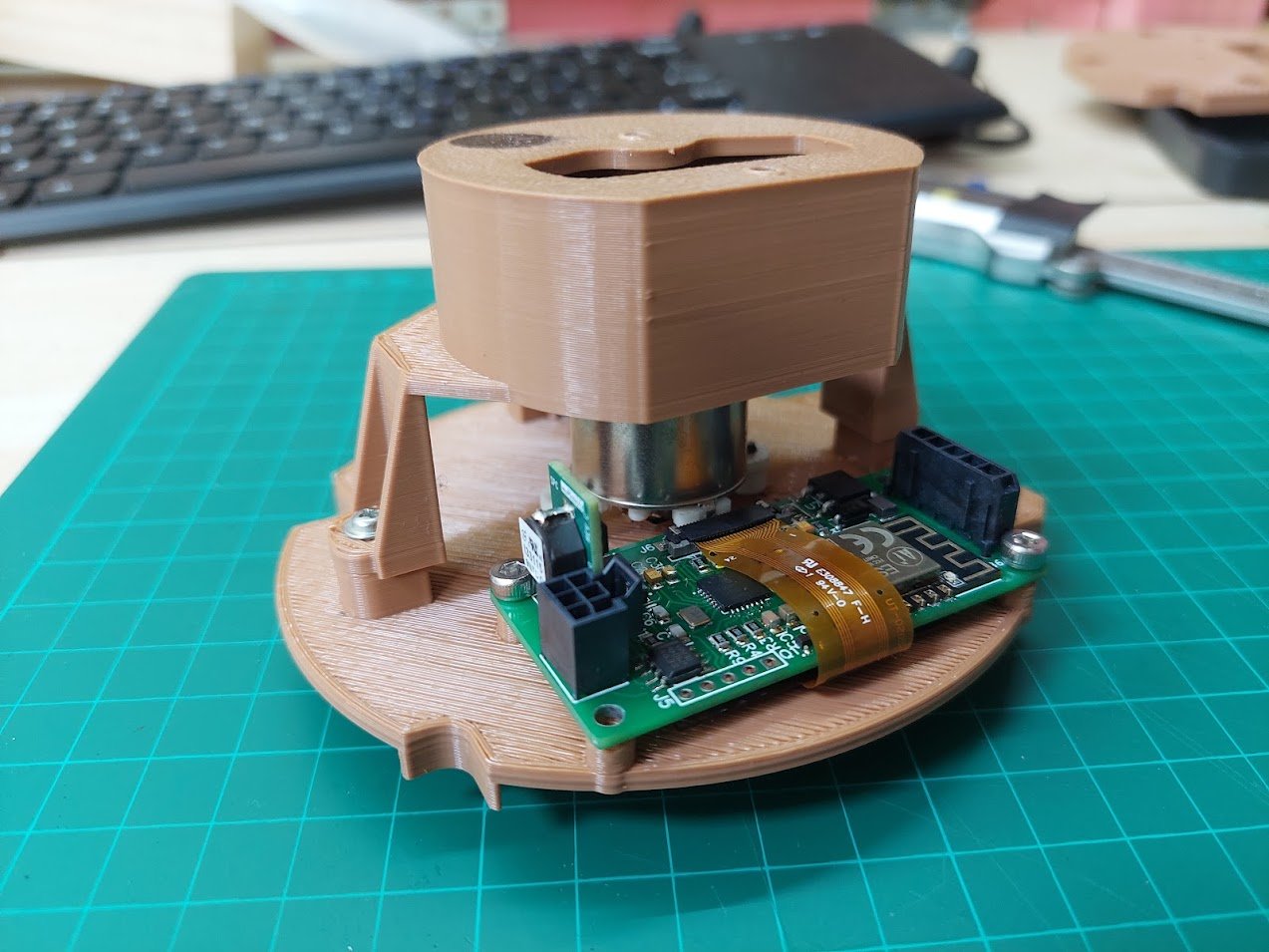
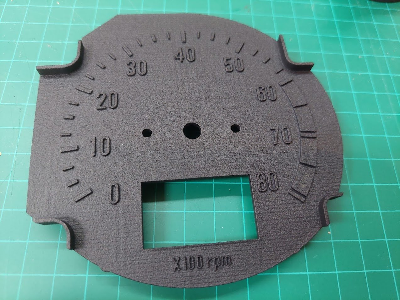
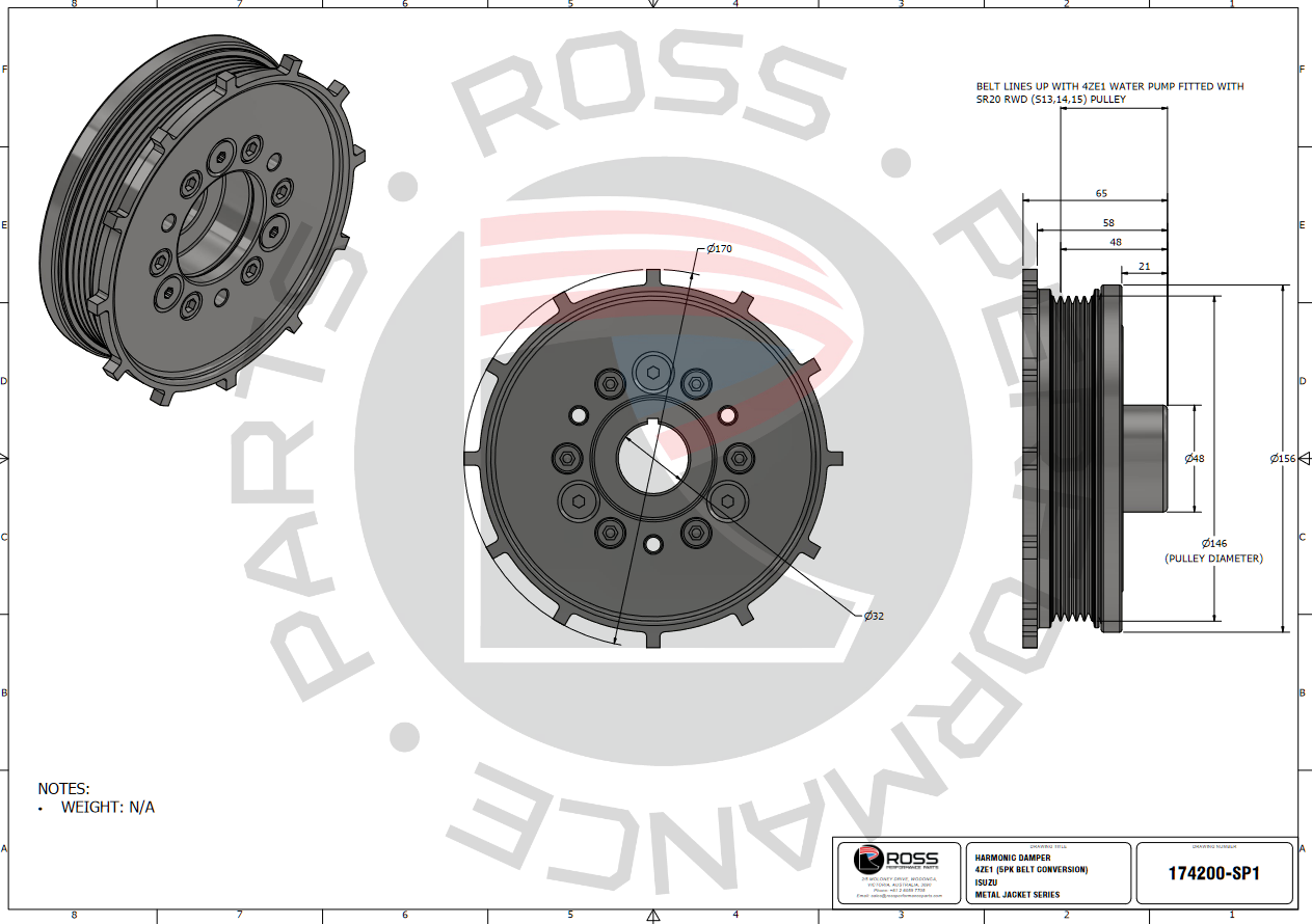
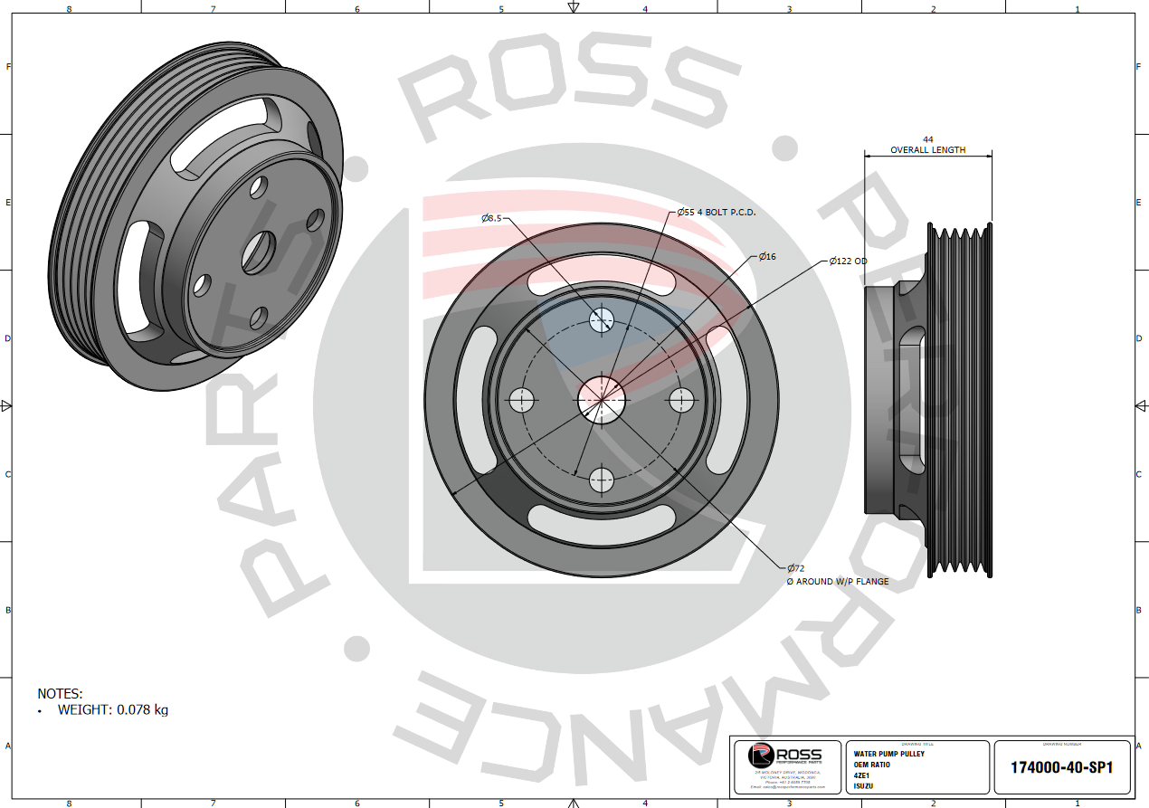
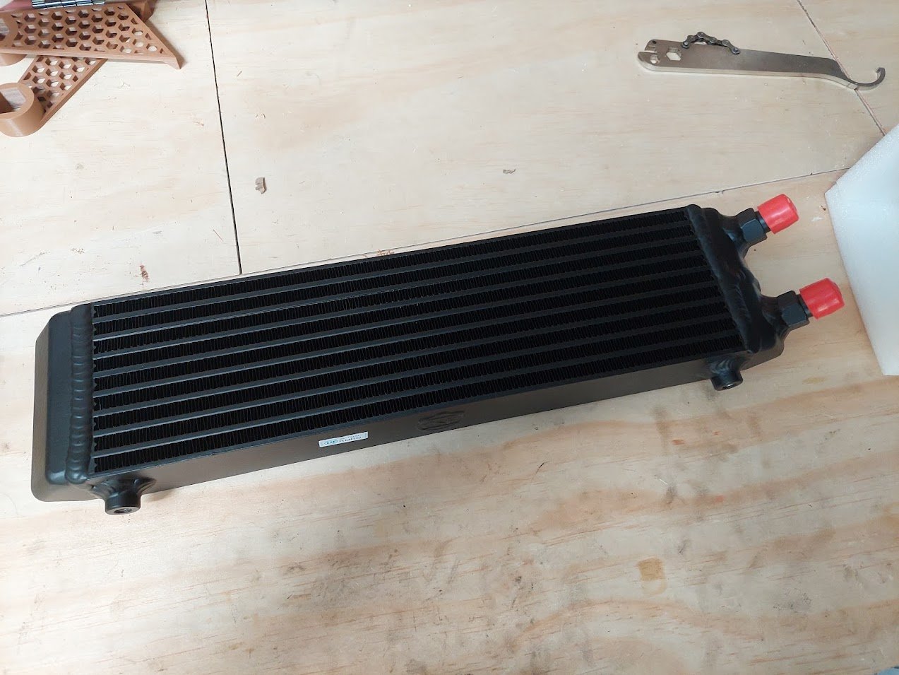
Wow! I really haven't updated this in a while. There's been a bit of progress in the last 7 months, but not a heck of a lot. I've been mucking around with brakes, dashes, diffs and cooling. In the end, I decided that shortening my axles the "build up and machine down" way was going to be okay, so I sent them to Howat Engineering and had 35mm lopped off and the splines cut back on. I then took the housing to Tin Tricks where it had the Gemini mounts cut off, was shortened and had the 4-link brackets slid on. I left the ladder bar mounts on so it still had a way to mount to the car when I had to move it. Turns out I was spot on with my measurements. The wheels just sit inside the arches - will need some work done to get unobstructed bump - and I have about 15-20mm clearance on the inside. So pretty happy. I've also spent a bunch of time prototyping up some parts with the 3D printer. Throttle body adapter: Brake caliper adapter: Master cylinder adapter: And for those of you who recall ages ago I was trying to make a new tacho face for my dash, I've gone in too deep. I've designed and printed up an adapter which uses all the stock mounting points and screws, as well as a new face which has the cutout for my CAN screen: I then had it MJF printed in PA20 nylon. Unfortunately it warped so I need to have another go and add some ribs in to strengthen it. I was planning to paint it myself using modelling paints, but I'm not sure that I have the ability. I spoke with Charlie's Pinstriping out west who said they could do it. When I get around to fixing up and printing a new version I'll take it up. Last thing that I've been doing for quite a while is working with Ross Performance in Australia to develop a harmonic damper and water pulley for the Isuzu 4Z engines. They have pretty much finished, I'm just waiting on one or two people to test some 3D printed templates to make sure everything lines up. And lastly I have been talking with Skeleton Welding down south to build me a new radiator. It's been a bit of a packaging saga to try and fit the radiator, intercooler and oil cooler up front. But I think with a bit of ingenuity I'll be able to make it work. Speaking of the oil cooler, I got this "cool" one from CSF: The car is now in at Shores NZ having the 4-link boxes welded in and the rear turrets strengthened for coilovers. So progress is happening!
7 points
-
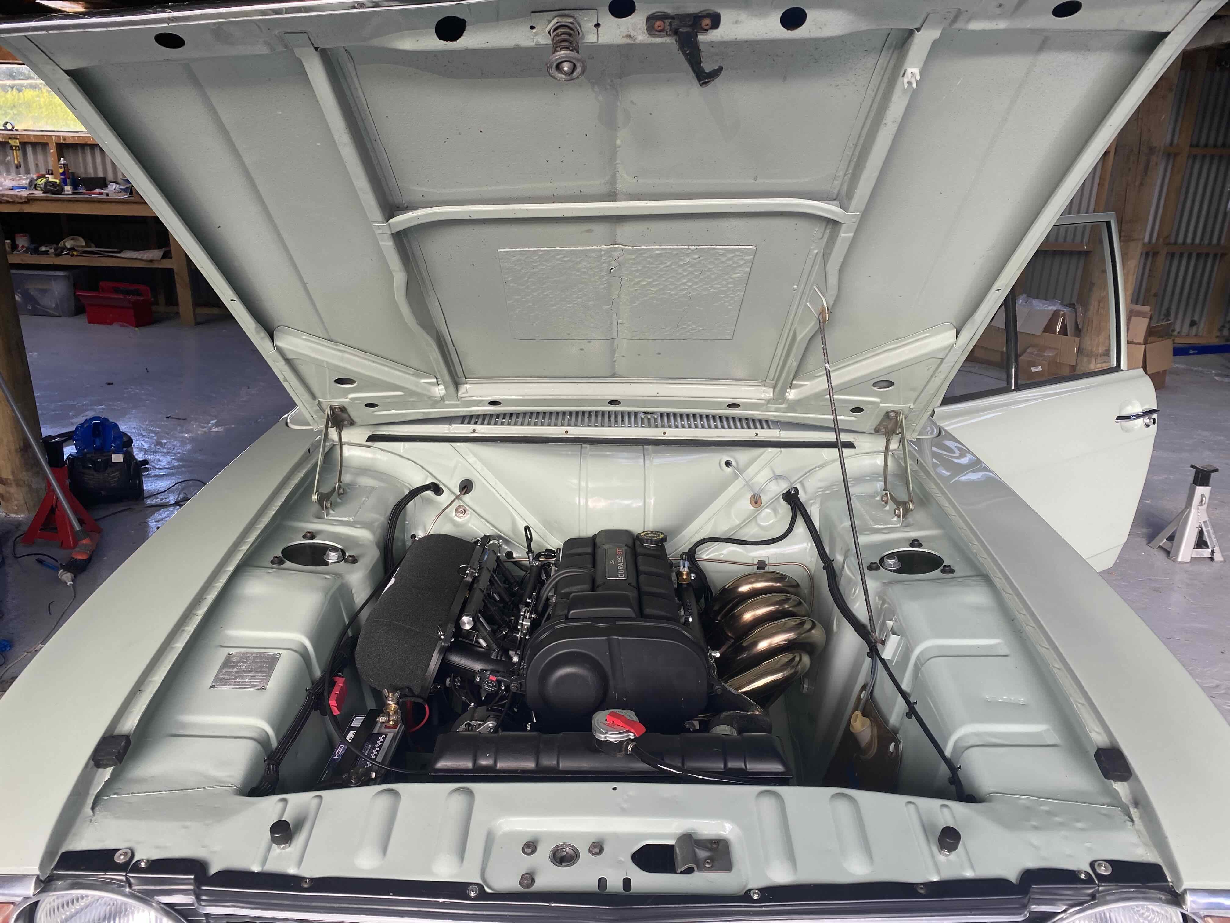
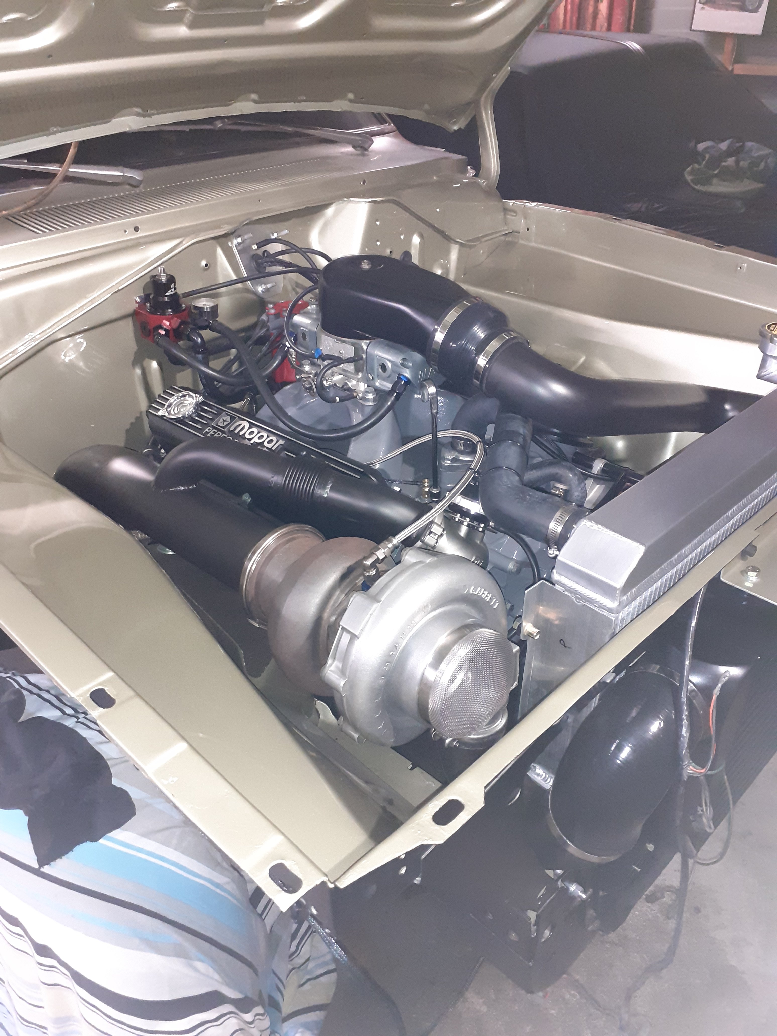
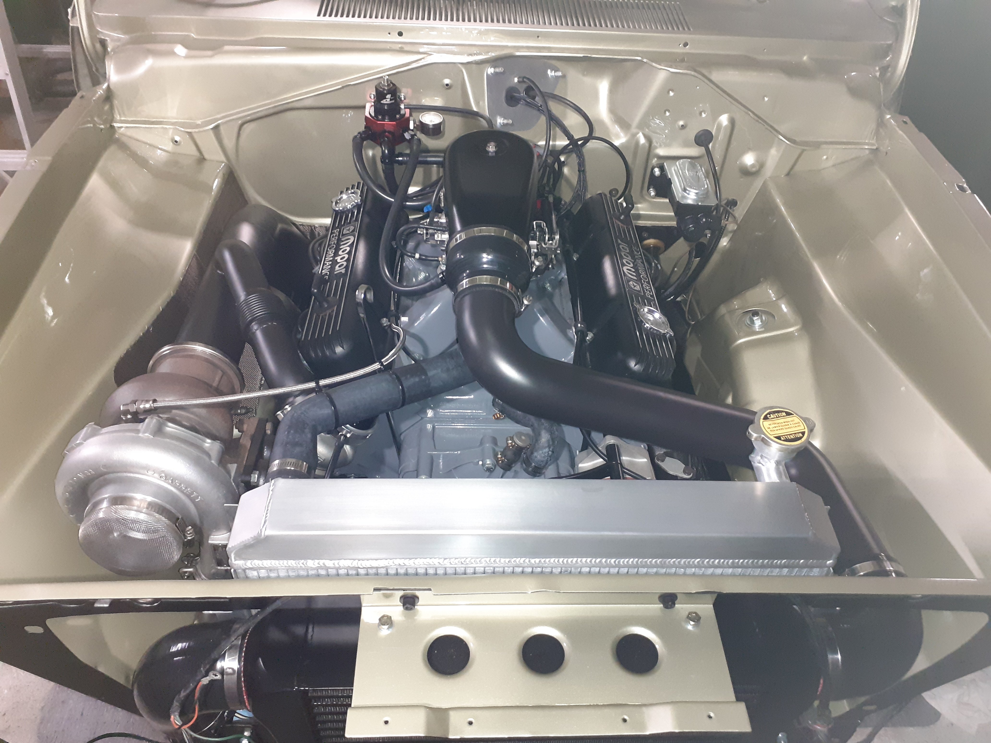
Engine is an easy fit... seats mounted ecu in gear shift working, have a radiator need to work out airflow and water plumbing front to back, or is it back to front... still a big list but chipping away at it.
5 points
-
She came back on Sunday morning. despite putting bungs in all the holes then electrical tape over the bungs, and stuffing plastic into the rear quarters; still managed to fill the rails and quarters with wet sand. If it wasn’t wet it was ultra fine silica sand and goes every fucking where especially eyes..it’s been in the shed with dehumidifier on ever since and I’ve spent hours blowing, vacuuming, slicing around down seams with a hacksaw blade, digging it out with my fingers through the holes and sweeping it. It looks grouse though..did expose about 20 pinholes and a few weak areas I needed to address. Feeling confident, I booked the repair cert inspection for Wednesday and started into it the evenings. Several engagements popped up which will hinder progress but yesterday I got the call to say the garage company wants the shed levelled by Wednesday to rip up the pad and start our new 4-car garage which is months late (summer) but earlier than their next ETA (deep winter). FUCK I should have the car done after the weekend, then have taken leave to pack, move and demo the current sheds. Having a bare metal car at this time of the year is shit. Not having somewhere at home to store it, or etch primer it after inspection (all going to plan) is shit too! Fear not: git ‘er done now, die of stress related health issues later..and try not to damage all our possessions it the damp weather
5 points
-
More mucking about, this time connecting the stripped down bike loom into the car, it'll be powered through a fused relay off the car ignition switch. I ended up writing three pages of notes on what each circuit needs to do to run the engine, some more simple than others and a few sneaky ones. For example the side stand switch is just a simple join the wires whereas bypassing the bike ign switch needs a resistor on a particular wire as the ecu uses it as a rudimentary antitheft device. A sneaky one which doesn't seem to be very well known is the clutch switch, most people seem to just join this one too but apparently there is an ecu feed on it and if you just join them the ecu will only detect the circuit activating once when starting so will think the bike is in neutral and run a fuel map for it. I just happened to have an appropriate switch so I'm just going to hook it up to the pedal and keep it as is. Having the big rust hole that I am yet to patch has been a godsend for accessing the wiring behind the dash but I still found myself upside down in the tiny footwell. I had to make a platform next to the car to lie on, then ended up lifting my legs up onto the seat so I wasn't banana-ing my back on the sill, 6/10 would trade again5 points
-
Major 2 are When were the injectors serviced last and has the IP had a rebuild. how difficult and rattelly it is on startup stone cold is a good test to see what itsb fuel system is like. then theres the usual of general servicing (oil, filters, coolant, etc). Those Era transits also use bolts to hold the manifold on which snap off in the head so an exhaust leak is a bit of a major to fix. There is a company here in christchurch called All Transit Parts which would be a useful contact for spares. Rear brakes trake a hammering for some reason too. I refuse to work on them now as most are neglected pieces of shit. Especially if theyre a camper van.4 points
-
Whittled the old front panel off. Realised later I should have also removed those flanges on the front of the inner wings.... the new front panel already has them. But that will make it easier to flatten out the damage in the front of the drivers inner wing. No photo, but I offered up the new panel. Bloody hell the edges are sharp. Cut my hand.
4 points
-
4 points
-
4 points
-
This and people think their random assortment of high dollar aftermarket parts will all magically work in unison to produce the optimal result. Testing testing testing is how you get results4 points
-
Not much to add since @Roman has it covered, Although a graph would be nice? The few bendy runners ive used. the centerline measurement seems to line up pretty well with a straight runner. in regards to length tuning4 points
-
Would have been fine if the fiat was a perfect sphere in a vacuum4 points
-
Theoretical improvements yield real world disappointments4 points
-
That is my theory, then it doesn't matter if the engine is a cast iron turd from the 60s, force feed it and all is good. I have wondered how much more power is lurking within, if I had roman/kpr levels of tuning smarts though3 points
-
Reminds me of a story from my old boss, building up a 2L Fiat twin cam race motor. He did all the math on cams intake and exhaust runners to get maximum power. His mate built the same engine with slap together parts and guess work. Guess which was the better performer of the two?3 points
-
Hey man, @yoeddynzpointed me in the direction of your thread over on Retro Rides. What a read! I was wondering if you might want to be a guinea pig for some of the stuff I'm working on around tuned length runners. It's got calcs and stuff, and I'm sure there's a graph or two that could be knocked up from it For a long time, I bought into the idea that inlet pressure waves were caused by air piling up against the back of the inlet valve as it closes and bouncing backwards and forwards along the inlet at the speed of sound until it reaches an open valve again. Apparently, according to the bods on Don Terrill's Speed Talk who are much smarter than I am, that's not how it works at all! (or, rather, that does happen but it's nowhere near being the dominant effect). What actually happens is the piston creates a strong negative pressure wave as it reaches its point of fastest acceleration (usually somewhere around 84-90 degrees of crankshaft rotation). This propagates up the inlet until it reflects off the atmospheric pressure at the end of the inlet and returns as a positive pressure wave back towards the inlet. What you want to do is size the inlet tract so that positive pressure wave arrives back at the tail end of the same stroke that created it, when the piston has slowed right down at BDC, or has even started coming back up the bore. So far, so easy to calculate. The issue is that the atmospheric pressure the wave bounces off at the open end migrates down the runner a distance that's dependent on the strength of the negative pressure generated by the downward movement of the piston and the diameter of the runner. As this is the complicated stuff that programmes like Pipemax does and I haven't worked out yet, the best I can offer is to get into the rough ballpark for trial and error, with the possible suggestion that if it's not possible to fabricate a short enough runner, you can step up the runner diameter to make it appear shorter to the pressure wave. I've made a little calculator so people can plug in their engine's specs and get a rough idea of what inlet lengths to aim for, and which ones to avoid. You'll need to know your target rpm, your stroke, your rod length, and your cam timings (actual measured cam timings, not advertised as they're often quoted in deliberately obfuscated or incorrect ways). Ideally your inlet temp would be useful too, but that's not too tricky to estimate. It's a little crude at the moment as I've no idea how far the atmospheric pressure travels down the inlet, but it should give you a rough range to aim your inlet tract length to. Would be dead interesting to compare the numbers the calculator spits out to the various different lengths of trumpet you've used. I think the only thing that would need to be measured is the length of the inlet tracts and the opening and closing times of your cams/valves (would need to be measured using a dial gauge and degree wheel, published specs are usually junk). If I can work out how exhaust length tuning works then it'd be interesting to see how that matches up as well. The usual aim with exhaust runner lengths is to tune them for the trough caused by your tuned inlets so you get minimal reversion and a smoother torque curve. If one or other of your inlet or exhaust runner lengths are dictated by packaging then you could try and tune the length of the other one to compliment the length of the one you're restricted on... Sorry for the wall of text!3 points
-
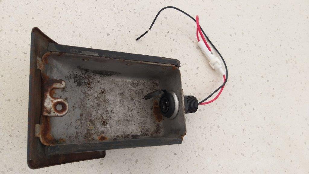
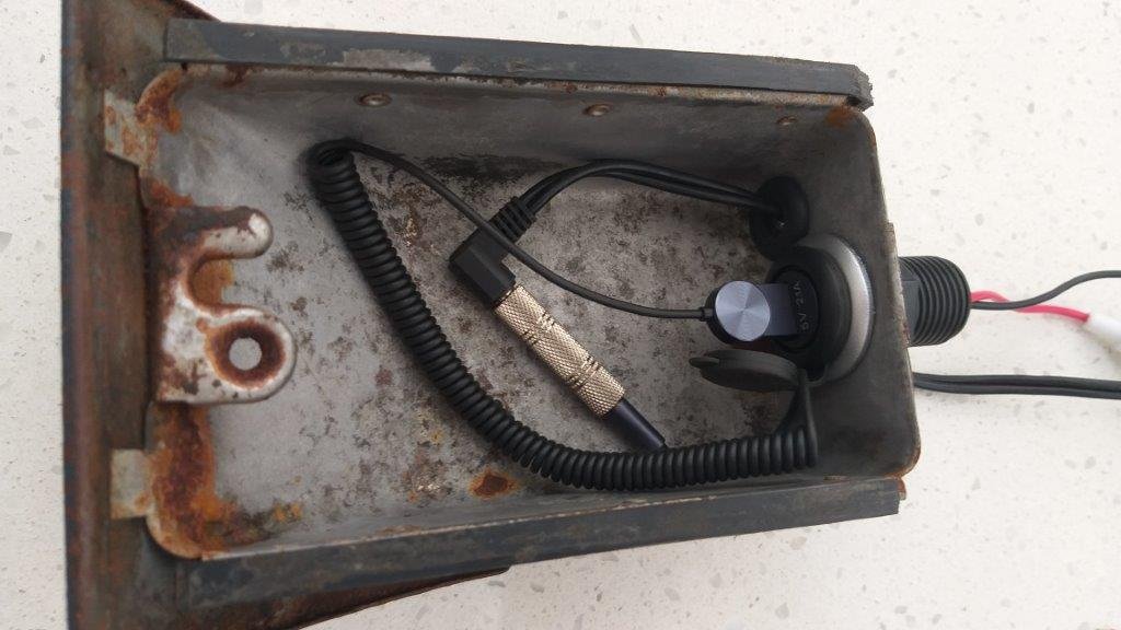
Before I clean up the rest of the ashtray I thought I'd poke some holes in it. I'm never going to use the ashtray, so it is getting a second lease on life as the hidey hole for the USB power socket and my blue tooth dongle for the head unit.
3 points
-
I picked this little thing up ages ago from Fronte fiend @Goat, good things take time but I just fuck around heaps so I'm only now making some progress worth posting up. Hopefully some peer pressure will give extra motivation.2 points
-
Fitted main bearings and crank today Cheap and cheerful one size fits all rock auto bearings are within spec which is nice Smidge bigger than 0.02 which is factory spec ish so that's a win Will do pistons/rods/arp rod bolts tomorrow. Attempted to fit oil pump today and managed to mangle that seal. Luckily I ordered another by mistake with my last amayama order so that should be here next week2 points
-
Oh how things changed! Sep 2021 I was definitely feeling a bit low after all the Covid shit and endless lockdowns over here; amazing considering now I'm the opposite. As some of you would've seen I now have my own shop to tinker and work on projects of my own (but mostly mates at the moment it seems). This is separate to Moonlight Racing which is in another shop aaages away; and this shop is called Karaage Garage. Anyway, I digress. Today I didn't really have much of a plan aside from get the crusty mirrors/mirror mounts off (I reversed into the side of a shed so broke one of them off already). It seems like one side (which I also reversed into the shed but didn't hit the mirror) had the captive nuts still in the back but the other side (which I hit the shed with the mirror) didn't. This meant I had to take the inner door liner off which isn't really hard when most of the clips are broken and and use a bendy ring spanner to hold the rusted af nuts while trying to get out the bolts (which for some fucking reason the previous owners like to use Allen head bolts on everything). Got that shit off and now looking for some new, not crusty plastic mirrors. I'm not too worried about drilling new holes in the door, it's fucked anyway but it would be nice if I didn't have to. With that task done I set on "fixing" the driver door hitting the guard when it opened. This is the side I hit the shed but not the mirror, so where the fender winker is got banged up and it pushed the fender back. Anyway I just used some guard rolling/magazine/cardboard technique on it and now it doesn't contact, success. After that I thought I'd Barry it up and get some of the panels lined properly (hahaha) and the doors closing a bit better; so I did some arts and crafts. Painted these black, not sure why? Had some black paint around. Cool to see the old Toyopet logo stamped on them though. Passenger door is closing real nice now, driver door is actually sagging a bit so not super good but a little better. I think the door rubbers are kind of cactus so if I got new rubbers it should make a difference as well. It seems like there are door pin repair kits available so will look into it. Otherwise just vacuumed the dust and wood chips out of it from when it sat at the wood factory. Oh, and found the spare tyre (can't believe I never actually checked it before) and it miiight be original for Australian models. Not sure exactly but these tyres stopped production in early 80s from what I can tell so could be, or at least it's super old. Still holds air. Never actually seen a tyre that was made in Aus before. Also struggled for about an hour trying to get the clock out where I'll re-use that hole for an A/F meter as I have a spot for a probe in the headers I believe. Talk shit here2 points
-
I can get some out of the states if I have to The factory Sr20 wingroad doesn't exist on amayama or in any parts lists which is dumb because I want part numbers. I might even change the hubs to something 114.3x4 to match the disk rear The ones I posted are available in nz Was one at tga pick a part a year or so ago
2 points
-
Calculators have there place getting you ballpark. or if have no idea on starting point. can cut down on testing time, if that's the case. Or at least a good learning exercise. As a lot of people still seem to go with a blanket "shorter is better for high rpm, long is better for low rpm" Yes if make the runner shorter it will push the tuning higher in rpm range. The part they miss is, if make the runner longer and drag one of those previously unreachable peaks down to where the engine naturally wants to make peak power. you have just had a big win. as said peak you have pulled down, is stronger than if you shortened the runner, to push a peak up the rev range. Plus you get the benefit or pushing all those other peaks down the rpm range and gaining midrange power as well. you can see this in my videos pretty clearly. if the runner is too short and the peak falls off the end of the rpm range. it chops the top off the power curve. So yeah im actually using the longer runner to make more peak power which melts most peoples brains There are of course other things to overcome than just length. but yeh, gets you most of the way there.2 points
-
Haha I expect you're right, although without a working engine (or a working car for it to go in) all I have at the moment is mucking about with spreadsheets! Interesting to see if they can point me in some sort of direction for when the other bits start falling together. Would be interesting to see if it bears any semblance to reality or not. Very familiar with @kpr's videos. Awesome stuff. Was just as surprised at how well the peach slices did same with how poorly the super long intakes did, although that was before I knew about the water hammer theory being junk. To answer some questions about the scribblings, yes it does account for the offset of the crank (and the piston pin, which moves things back in the other direction). No, it doesn't do anything with working out how far the atmospheric pressure migrates down the runner, nor determines when in the intake cycle is a good idea for the charge to be targeted. All far too complicated things to determine with my level of maths! Best leave that to the empirical testing. What it does do is give you an intake length range where the pressure wave will enter the cylinder between 3/4 and 7/8ths of the inlet cycle. Anything more precise is way too complicated man2 points
-
Me too2 points
-
This ^ Pick up that jumbled up box of lego. do some illegal moves according to internet theory, and lots of testing2 points
-
Re driveshaft, easy way to think if it. is the shaft is going to be spinning the same rpm as engine in 1:1 gear. (usually 4th) Then punch the numbers into that calculator @cletus posted. Single piece becomes a bad day fast, on a high rev engine that will be generally matched with short diff ratio. if going to use it on the track etc I usually avoid running anything up on dyno in 4th gear with a single piece that's going to pull some revs2 points
-
I'd use paint stripper. The stuff from super cheap that has dichloromethane in the ingredients is safe for aluminium. Stinks terribly, I think it has ammonia in it. Works great for removing carbon from pistons and valves and stuff without scratching too. Don't get it on your skin, even a tiny little bit will start to burn in a few seconds.2 points
-
Depends on the car and application A long shaft has a lower critical rpm , a 2 piece shaft you end up with 2 short shafts so that max rpm figure is higher http://www.wallaceracing.com/driveshaftspeed.php A single piece shaft can be made to handle high rpm but then it has to be bigger Also depends on the combo. If it's a car that isn't going to see high rpm or speed then you will likely get away with it . However things that rev to the moon and or have overdrive gearboxes are more likely to have problems. I know of 2 situations where people put LS motors in old cars (one was a 57? chev and the other was an impala) and they spat driveshafts out on a dyno due to exceeding the critical rpm of the shaft. I wish I still had the pics of the impala, it nearly wrote it off, because the shaft lets go in the middle at high rpm it absolutely destroyed the floor, it was very fucked. The other trap is the tunnel shape, if the car was designed for a 2 piece shaft then they don't always have room for suspension travel and the front half of the shaft going up and down. Early commodores have that issue when fitted with a single piece shaft, they rub on the tunnel in the middle of the car, and it's usually made worse by the shaft having to be a bigger diameter In my VG when it had a good engine in it, I did a burnout in top gear once, it got near the rev limit and made a horrible high frequency vibration that I'd never felt before, I'm picking that was the limit of the stock shaft. I heard a story not long after that of a guy with a turbo 6 valiant that the shaft let go somewhere around 200kph2 points
-
Just a small but significant update today. With all the work on the column switches completed, this meant that I could finally take the car for a quick spin around the block to see how it actually drives and if it highlights any further issues. The cold start was really good, only needing a couple of turns to come to life. I wasn't too impressed with the top end rattle though, I will need to get some new oil in there and hope it's not a sign of things to come. The oil in there will be at least a year old, if not two, and I don't know what grade. Before I could back the car out of the drive I had to raise the steering column, as all the wiring work was done with it at its lowest height. Overall the car drove really well. The weird notchy feeling in the steering seemed to clear up, so hopefully that's just from lack of use. It tracked and drove straight, without feeling too rolly polly on the suspensions, so maybe it's not completely poked. The engine pulled well, although I forgot how lazy the autos are; but that's what I like about them. The revs stay low, and it just rides that low end torque and gains speed quickly without fuss. Say what you will about automatic transmissions, especially ones from the 80s, but this old GM 3 speed shifts beautifully. The previous owner claims it was rebuilt, but I have no proof of that. The shifts are smooth and seamless, and kickdown was snappy. I didn't check the trip computer, but everything else seemed to work. The gauges all rose, the speedo and tacho worked, and all the lights worked. The low coolant light worked a little too well though, the bottle and radiator are full, but the light is still on. Will need to do some digging. The Rover SD1 has such a commanding presence on the road. I can't imagine what it's like for the average joe to see one driving around in a sea of boring beige appliances.2 points
-
The first step in getting Lucas back on the road was to address the one issue I knew of when buying the car; the lack of a working indicator stalk. The previous owner told me it was broken but didn't say how or why, so until the car arrived it was a bit of a mystery. I could see in the pre-purchase photos that the column shrouds and stalks were missing, but knew no more than that. Upon arrival, the car came with the stalks missing and the shrouds on the passengers seat. There was an icecream container in the back seat with the remnants of one switch, and what appeared to be quite a new, albeit incorrect side, indicator stalk assembly Assessing the stalks, the disassembled one was very likely the original broken one, so that's where I started. If you have been following my posts for a while you will know that I'm a big fan of fixing what I have, instead of just throwing new parts at a problem. This was no different. I could tell immediately that the high beam detent on the switch was broken, which would cause the high beam to fail to latch and stay on. The plastic piece that causes it to latch should be sticking up in the gap the arrow is pointing to. Now, I can't find it, so I may not have written about it, but I have done this job before. Not for the detent, but to fix a broken horn wire. 99.1% of the job is exactly the same, so I had an idea of what I was doing. The donor was the mint condition mirrored stalk. This is either from a different car that uses a similar switch but has the indicator on the RH side of the column, or is from a LHD. You can see that the stalk is upside when on the correct LH side and bent upwards. There were a couple of other differences too; the connector was the later "church window" style, which the car didn't use, and there was that random blue wire coming off it, which had no place to connect to. The first step is to VERY carefully remove the metal plate from the front of the switch. There are two small machine screws, and then it hooks in under two plastic tabs near the stalk. Once the plate is off you can see the gubbins that makes it all works. Be careful though, at the top and bottom are detent springs and plungers that can and will make a break for freedom. The top one should have a ball bearing under the spring, and the bottom one a plastic wedge. The white collar for cancelling the indicators just lifts out, and then so does the central mechanism that the stalk moves (the big black piece with the white arms on it). Be careful here as there is a copper roller, spring and plastic plunger in this section that will drop out. With all that removed, you are left with the rear housing and the stalk. It's interesting to note that the three long contacts for the indicators are mirrored on the opposite-handed stalk. The top holes are populated on one, and the bottom on the other. The detent needs to be released from the back casing, by carefully pulling back the piece of black plastic on the back that is holding it in place. It can take quite a bit of force to pull it out. Here it is removed and flipped upside down to show the notches it locks into fr high beam. That's the part missing from the broken one. Now its time to get serious and cut the two wires that run through the switch and into the stalk (one had purple and black, the other was purple and purple with a black trace, but it's obvious which two run to the middle of the stalk) and then the stalk can be removed. Now, I couldn't just swap the stalk over, since it was upside down and bent in the wrong direction, so I had to remove the detent piece and swap it to the existing stalk. To do this I needed to remove the little plastic block on the end. Be VERY careful with this as it is super easy to break those little round ears off and render it useless; DO NOT use those ears to support it when you drift out the shaft. I lightly held the stalk in some pliers on top of the vice, and used a punch to drift the stalk out through the block. Oh, and it helps to mark the position of the block beforehand, so you can have the stalk rotated the same (or it may not face quite forward). With the block removed, the detent piece just slides off and over the wires. Do the same to the good stalk, and swap the detent piece to the original stalk. Now line up the block with the marks you made, making sure the horn ground wire is tucked under the block and wraps over the top, and then gently tap it into place again. I gently held the stalk in the pliers, clamped in the vice and used a small hammer to tap it back into place. Congrats, you now have a good stalk, that isn't attached to anything. Give it a good clean, and let's reassemble. Reassembly is quite simply the reverse of disassembly. The only thing I had to change was to move the wiper contact over from the top hole down to the bottom hole in the central mechanism. I did give the contacts a quick clean, and lubricated everything with dielectric grease. The front plate can now be gently reinstalled, making sure it sits flush and the plungers haven't fallen out. Now flip it over, and solder the two wires back onto the harness. With the switch reassembled I could plug it in and test it. I got a bit cocky and reinstalled it first. And we have dash lights! Gosh, I love the green illumination in these cars. I was well chuffed. Until I wasn't. We had dash lights, park lights front and rear, and flash to pass, but no dip or high beams. Damn. I connected a known good bulb. No change. Tried a different headlight switch. No change. Located the dip beam relay and swapped it over with another. No change. So it was time to grab the test light and start probing around. I had traced the wiring diagram back and had an idea of where to start looking; starting with the headlight switch Lots of probing later I was led to this mess under the passengers side of the dash. Ugh. That bracket with all the relays on it should be bolted firmly to the firewall, not ziptied to a bracket. Not a good start. I traced a few wires back and ended up at that weird white relay in the foreground. Turns out it isn't a relay, it's a "diode pack" that all the power for the dip and high beams go through. And nothing was going through it. I could see some traces of corrosion on the casing, so pulled it out and removed the casing. Well shoot, that'll do it. It looks like it's been under the sea. You cant even identify the diodes on the board, it's just a mess of corrosion. I got out the can of contact cleaner, and the trusty old toothbrush and got to work, cleaning away as much of the muck as I could. I then used my multimeter to check I had continuity where needed. A couple of contacts were a bit iffy, so I have them a quick re-solder. I plugged it in, initially without the housing on it, for testing. I turned the ignition on and flicked the light switch. No change. Damn. I flicked it off and on again, and suddenly I was blinded, the test bulb was glowing brightly. I had headlights. A quick check also showed that I had high beams too. Everything was working. Headlights, park lights, tail lights, brake lights, plate lights and fog lights. I refit the housing and bolted the relays to the firewall as they should be. One of the two bolts on that bracket I swear is the worst bolt on an SD1 to get at. Cant fit a socket on it, and it's one flat at a time with an open ended spanner. Some quick jiggling of wires to refit all the column stalks, and refitting the steering wheel came next. It's starting to look more like a car now. Heck, I might finally be able to take it around the block tomorrow after work. Hype! I still need to refit the column shrouds, but that will come in due course. One other thing I noticed when I was messing around in the car, was that this sweet old Clarion radio still works perfectly, auto electric aerial and all. Awesome retro design. Shame the plastic surround was broken and someone has bodged it with bits of interlocking foam floor mat...2 points
-
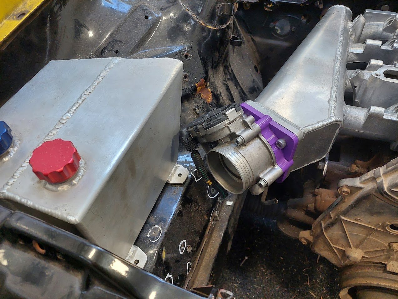
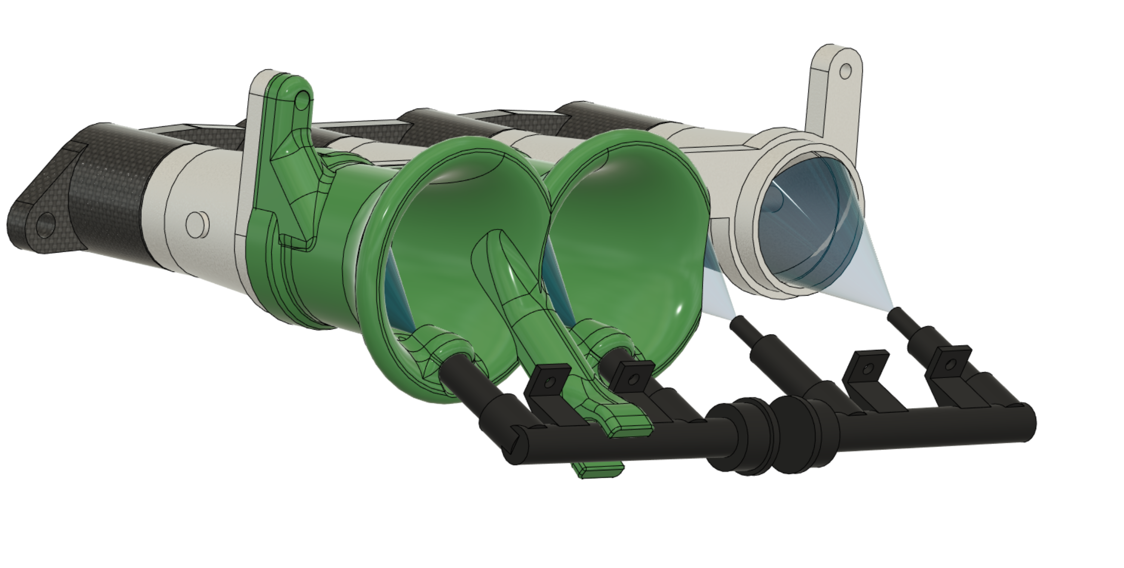
After about 8 revisions I've made something that fits, doesnt hit the bonnet, seems sufficiently strong on the fuel rail support and blah blah. I've basically run out of other filaments at the moment, so all I had left was a roll of ABS+ that I've not been wanting to use because it stinks when you print it. But it's actually printed quite nice without any warping. But I think it goes a bit soft from exposure to fuel after a few days. So first thing I did is get the motor tuned to be 100% bang on fuel target, using the injectors and fuel rail moved to the "inner" position mounted on vacuum side of the throttles. So when I move the rail and injectors to the outer position, I can look at the comparative lean/rich condition. If it goes lean everywhere, it's probably a bad sign - means I'm losing lots of fuel to reversion or something. I dunno, see what happens? Well, surprisingly, after moving the rail. Is pretty well bang on. Interestingly there are some areas where it's now running rich, rather than lean. Better fuel mixing? The car drives, cruises, and generally behaves just fine. It hasnt felt super soggy on the throttle or anything either, but I have beefed up the accel enrichment a lot. This is a full throttle run, with injectors placed on outer position. You can see the lower rpm area where it runs a bit lean - this is probably where you'd want to use mostly inner injectors instead. Then start phasing the outers in after that. When driving it, the car's felt like it's more eager to get to the redline. Virtual dyno looked to agree, to the tune of about a 5hp bump towards redline. But I think I need to do some more testing before I believe the initial results. Once I've got some less dodgy trumpets printed from a better material, and my ECU fixed. I'll see if I can get back to the dyno and do some proper comparisons.
2 points
-
Got the shock moving again so now it’s got some slam. My spare lowering blocks don’t fit the bottom plate so I just loosened the old ones right off for some static sag, hahaha. The seats are still soaking wet,so not installed.. the mesh visor is just for a laugh, might be a bit goofy.2 points
-
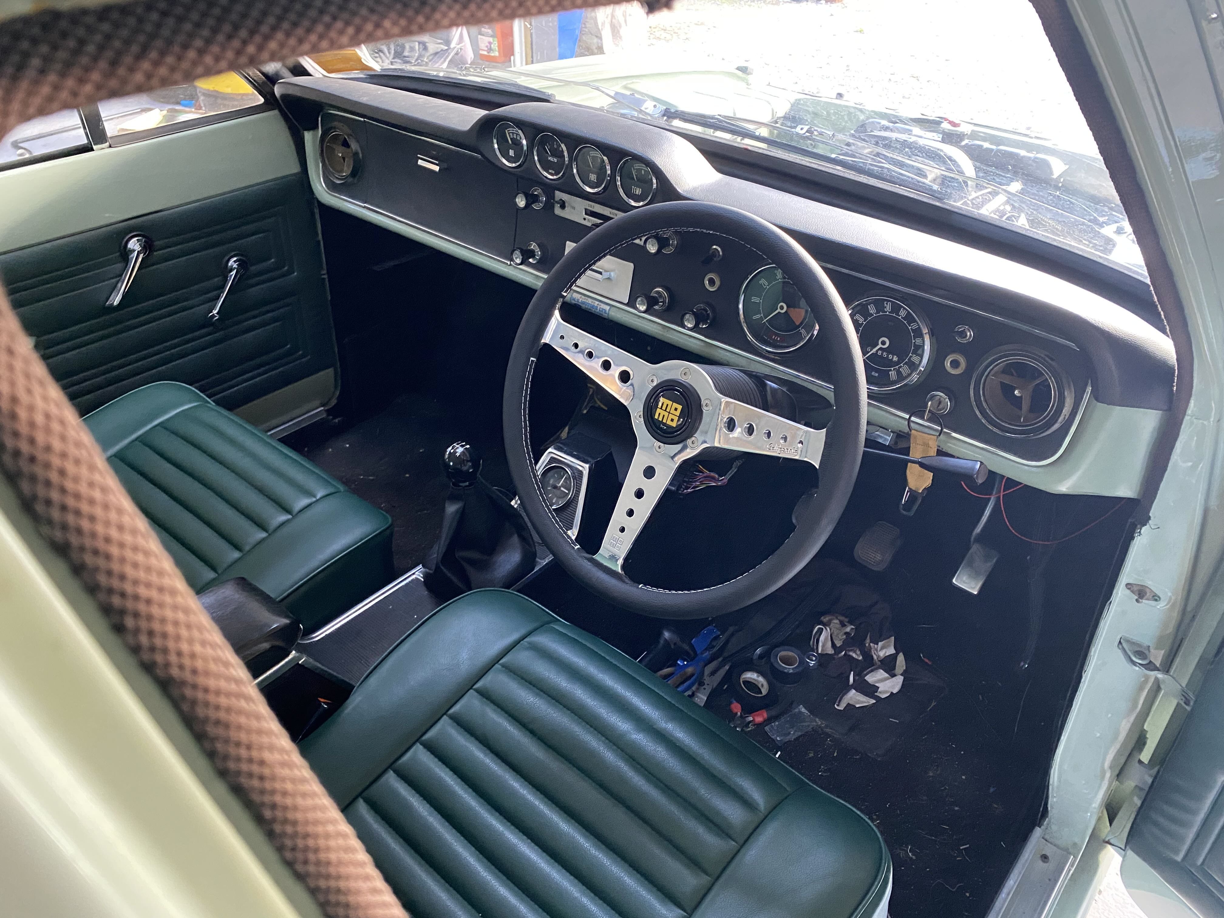
Still wrapping my head round the EFI/ECU life but my layman’s understanding after playing around for a bit is that my ECU isn’t sending ground pulses to injectors 2&3 which seems to be my issue. Injectors 1&4 are on a different pin from the ECU. Hopefully not too much of a drama to sort out. I’ve been plodding along with the interior, have managed to get all the gauges working, including rev counter which is a bonus. Slight issue is that the old 1968 rev counter only goes to 6k rpm’s, where redline in the ST170 is 7200, I’m going to try and rig up the shift light output from the ECU to be where the old generator light was in the rev counter at 6500- really need the engine to be running properly before I can see if that will work. Speedo and rev counter still need to have the outer bezels attached but that will come after final install. Have an underdash parcel tray to go in also but will hold off on that until everything else is finished. Could wait to try out my Xmas present from the better half- a nice Momo California which tops it off I reckon. She also made the shifter boot .
2 points
-
Borrow petes fezza brakes https://www.instagram.com/p/CeFoyH1OQkt/?igshid=YmMyMTA2M2Y=1 point
-
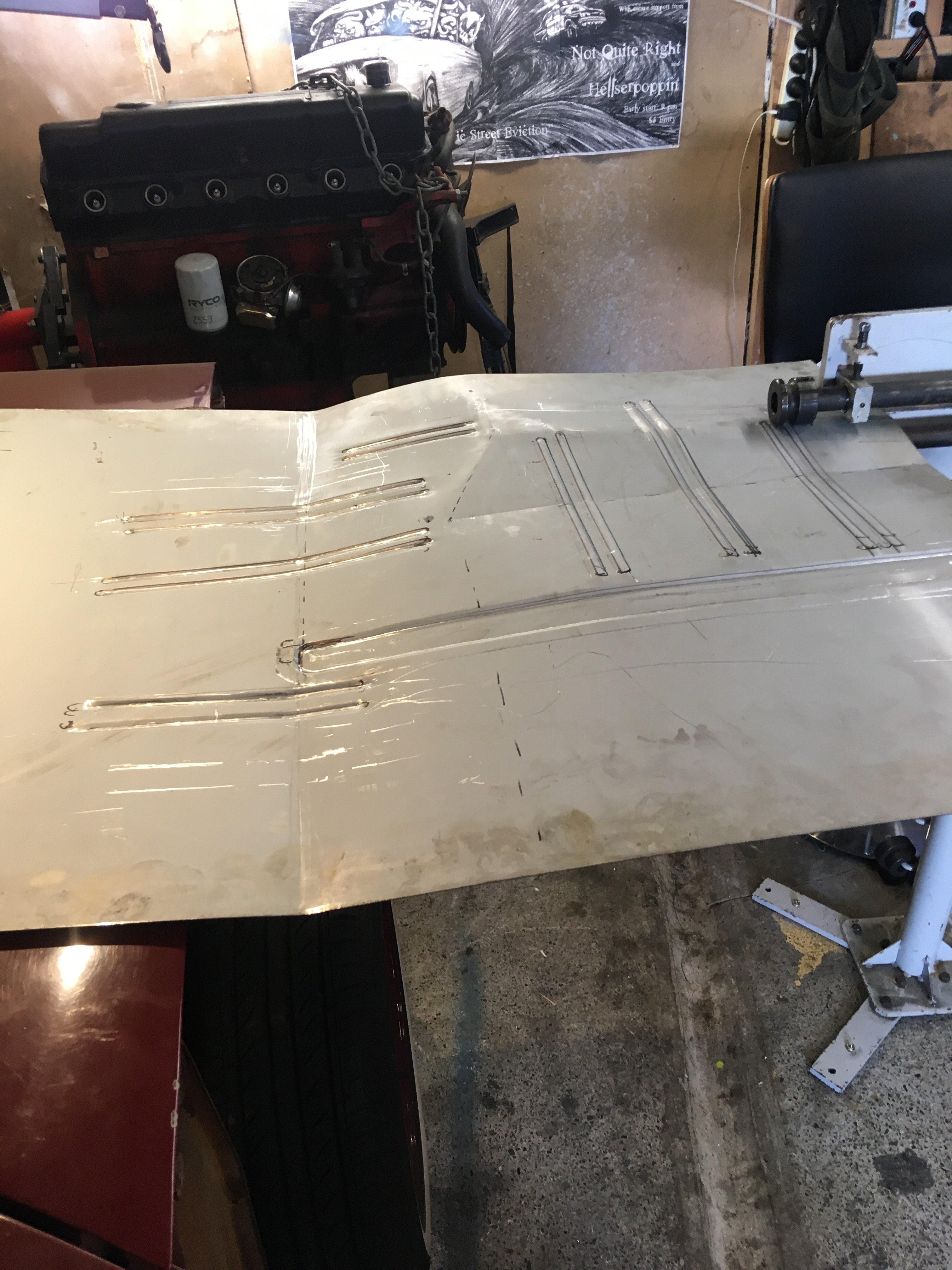
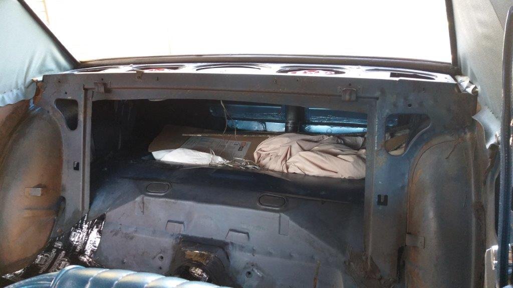
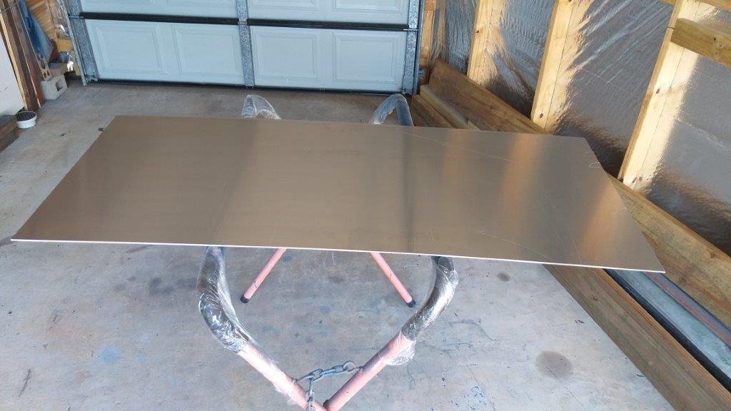
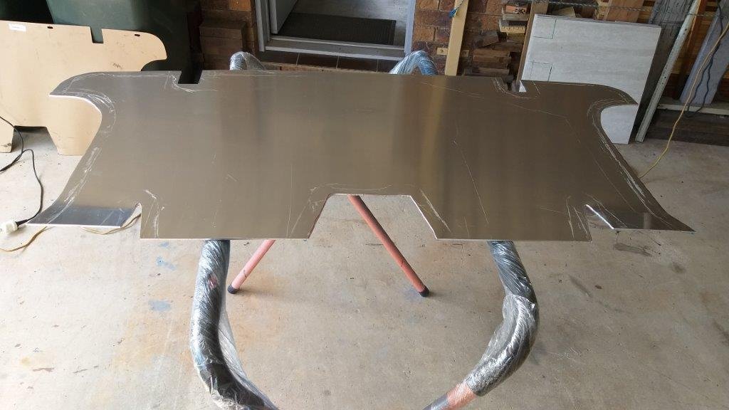
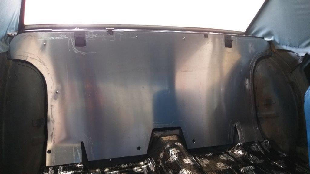
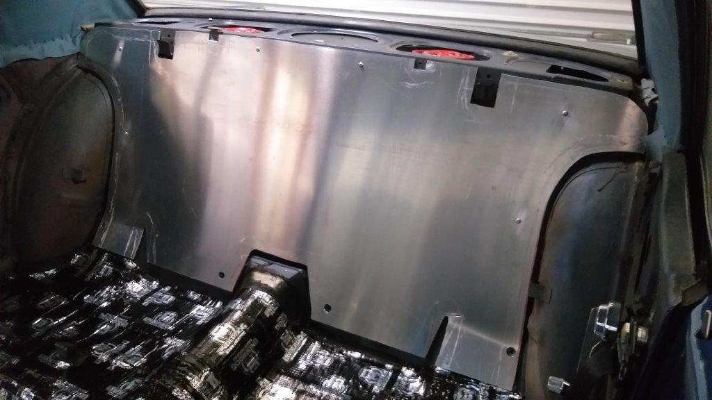
This morning I turned my attention to the panel that separates the cabin from the boot. I'm not sure how robust the original factory panel was, but my Muzzy has been fitted with one of Scott Drake's replica items. The little production label tells me that this beauty was manufactured on 11th February 2014. It is made of only the finest hand picked 2mm cardboard and has obviously passed through the loving hands of a skilled Taiwanese craftsman. It's clearly one of Mr Drake's superior quality products and I hope that he is well proud of this achievement. Anyhoo from the date stamp I'm guessing it was procured by Tom the previous owner and fitted at the same time as the 3 point rear seat belts and the twin baby seat anchors. I'm not altogether unhappy as it has made a lovely template for my slightly more robust replacement panel. So earlier in the week I hit my old mate Cameron up for a piece of 3mm aluminium plate which I picked up yesterday arvo. First thing this morning I got jiggy with my jigsaw and in next to no time I had my own interpretation of this part. I managed to use some factory holes in the seat back brace panels to bolt the panel into position. Marking the holes had to be done from inside the boot and much fun was had squeezing my lanky 6 foot 2 frame into the boot to get them marked. It was well worth the effort. The 4 lower seat belt anchor bolts will hold the bottom of my new panel firmly in place when I refit those. All that is left to do is to poke a hole and fit a grommet for my new rear speaker wires and I'll also cover the new panel with some sound deadening when my next batch arrives. Apart from that I'm very happy with this improvement. Thanks for looking.
1 point
-
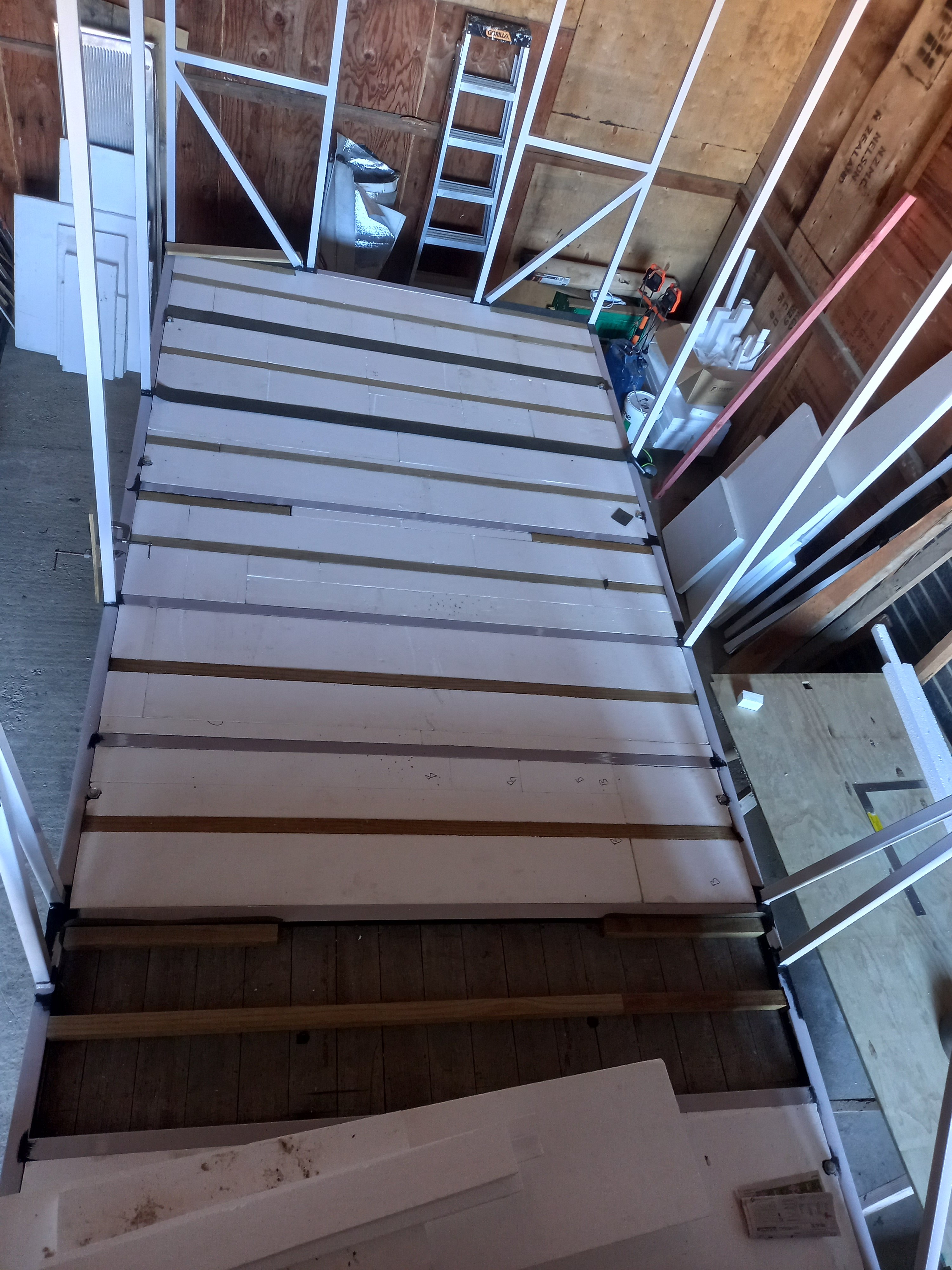
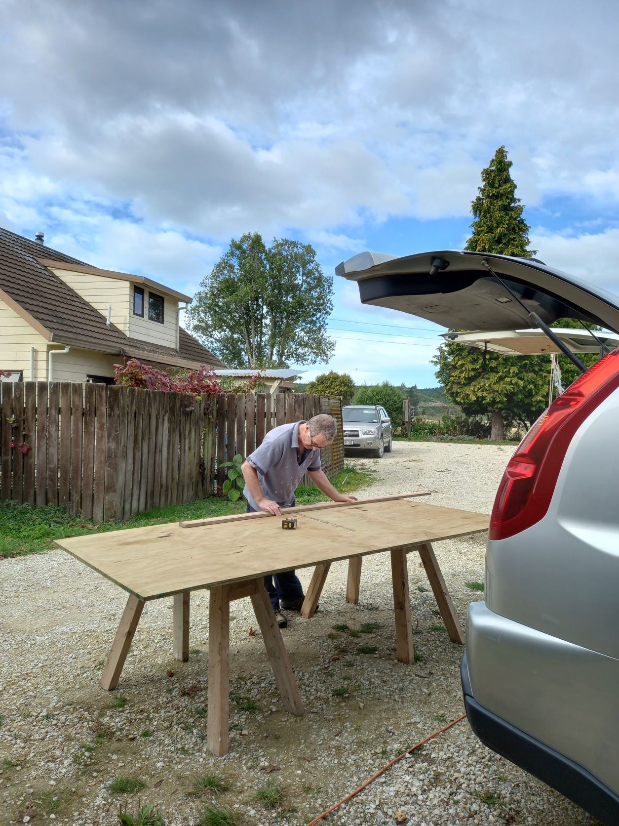
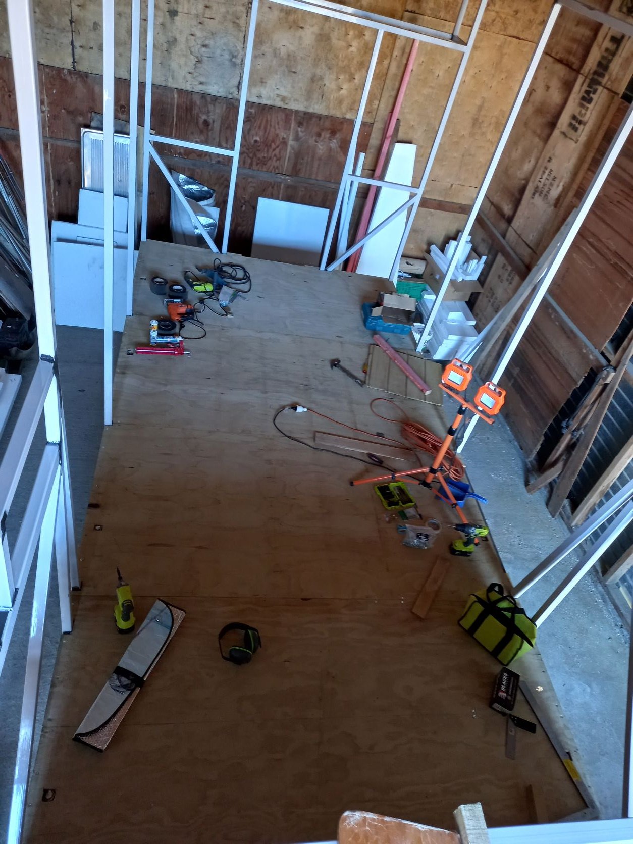
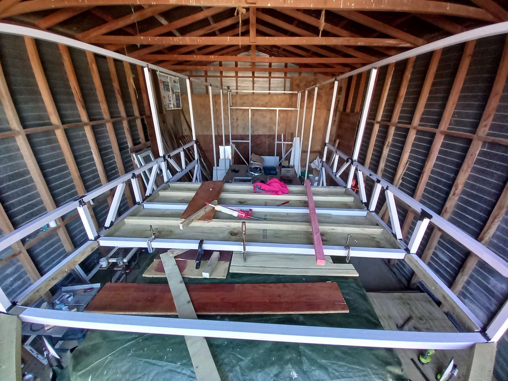
I must say being unemployed this month as made for a productive time working on Maddi If not always appearing fruitful there has been organising and planning as well, trying to think ahead to the next stage. It's been great to finally get stuck in and make some headway! The first mission was to get the floor down. So I got busy with the polystyrene offcuts that had been sitting in waiting, filled in all the gaps then came the fun part; learning how to to drill and screw into steel! It took some practice to get the technique right but with a few handy pointers form Dad and Lance I was away. Getting the 17mm ply sheets onto the tray also required some extra muscle which my brother was also awesome at providing. Next challenge was doing the 'under floor' on my bedroom loft over the cab. That took screwing into steel to new levels with odd angles and above my head! But of course I got there with my brother again helping with the lifting and clamping in place. By that stage putting the floor down in my bedroom seemed like a breeze with all of my 'expert' skills gained so far. And then all of a sudden I had a floor to walk and sit on without risk of falling through a gap, amazing!! The organising, ordering, collecting supplies and getting quotes for timber and roofing always seems time consuming but necessary. The the most exciting thing was getting the ply cut for my curved roof beams! I'll have 12 beams with 4 laminates per beam and as dad wisely said I didn't want to do them all with my jig saw if I wanted a roof before Christmas. As it turned out a friend of a friend has a CNC machine and was happy to help!! What a lucky surprise. And so the list of awesome people I'm meeting along the way grows. Plus I now have a whole bunch of cut outs awaiting the glue I've ordered. Progress
1 point
-
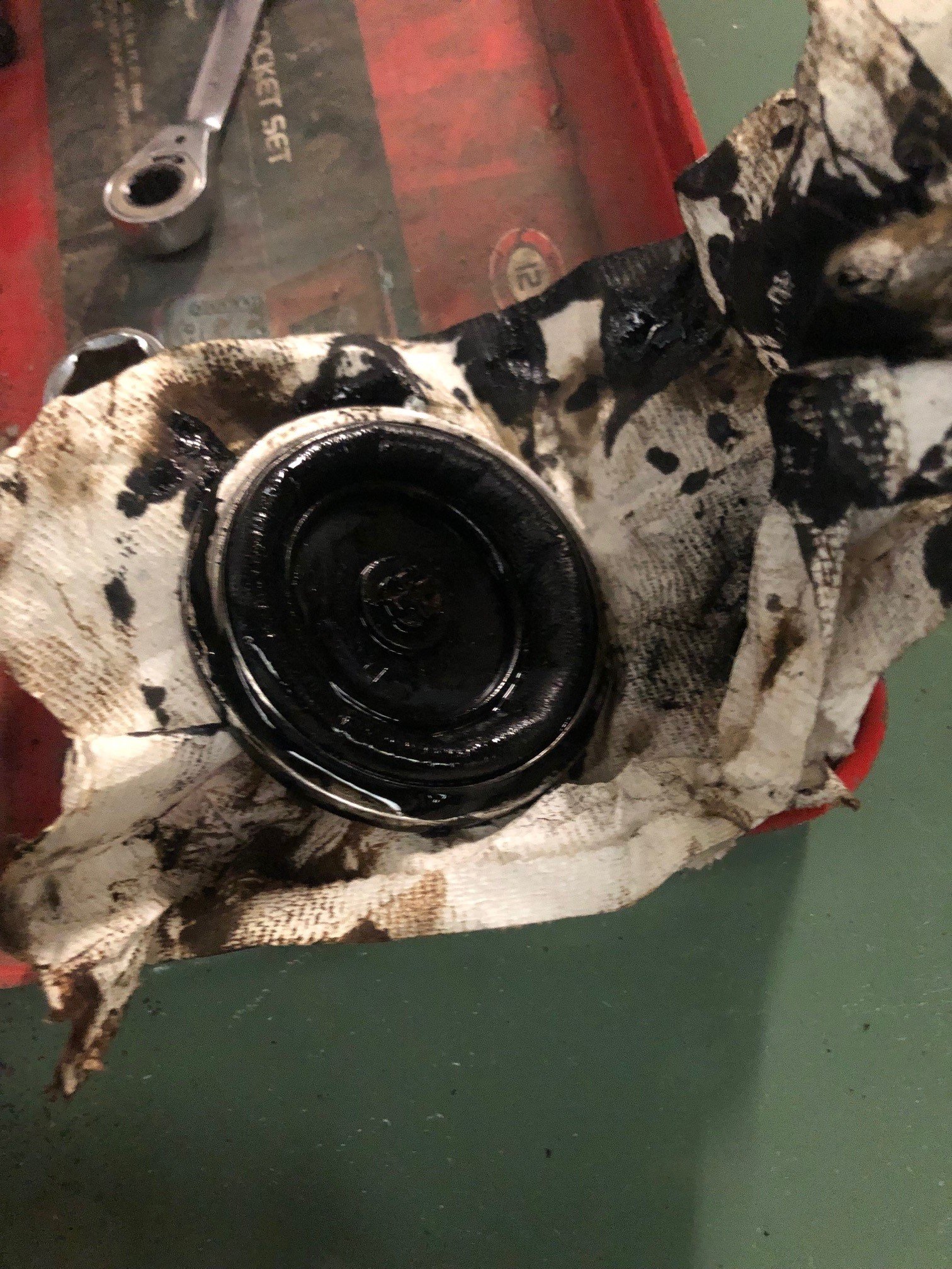
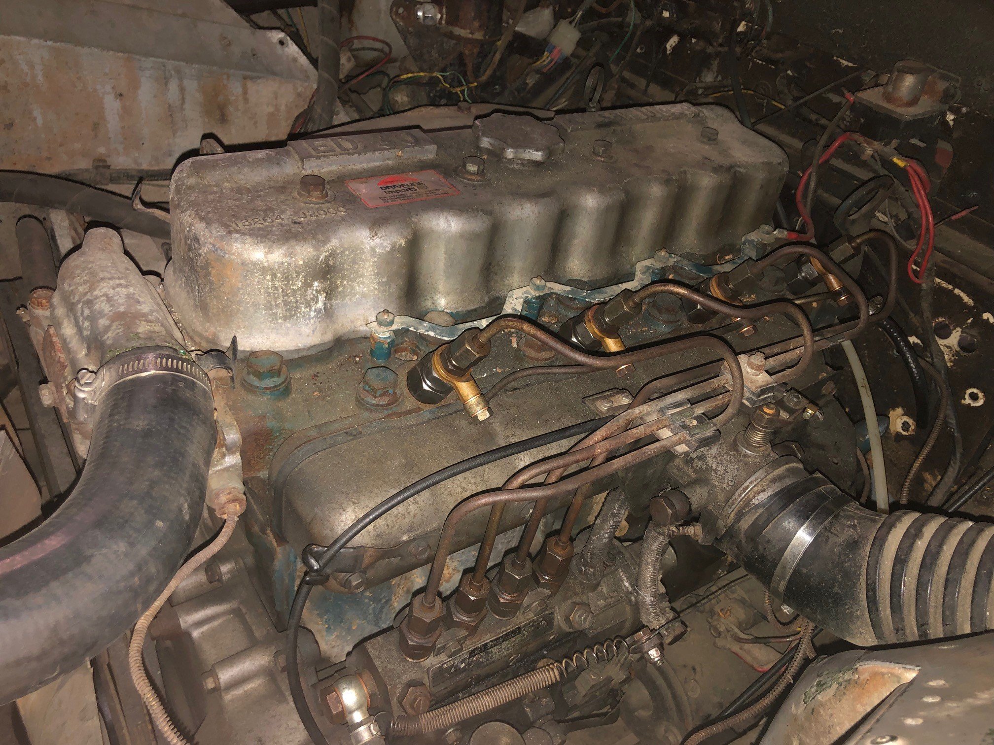
Now to have a go at the dieselly bits.... After looking around at the injector pump, and doing ALOT of googling have come to the realisation this is your standard Bosch A model pump with a pneumatic style governor on the back end of it. From my basic understanding, rather than a set of flyweights you have intake with a throttle butterfly with a vac take off pre and post the butterfly. Depending on the throttle position (and vac differential) it then moves a diaphragm which is connected to the fuel rack - kinda a pretty simple design - your idle and max fuel delivery is then defined by a set of adjustable stops on the butterfly. I found (this setup seems to be found in old mercs) that if the diaphragm is in poor condition then it can lead to overfuelling (my problem). When I pulled the housing there was quite a bit of oil in and around the leather diaphragm. It looked in ok condition so cleaned it up and refit. I suspect a seal has gone somewhere else in the pump (suspect shut off pivot) but I'm hesitant to pull down further until I see how it now runs. I had also sent my injectors away for a service, I was prepared for the worse but the Barrys said they cleaned up fine and were tweaked to spec. I had just enough juice in the batt to turn it over enough to bleed half of the lines and then fired up.... Certainly sounds alot smoother, and with a quick run up it looks to be much cleaner out of the exhaust. The diesel in this thing is several vintages old so I'm sure with some fresher stuff it'll do well.
1 point
-
They will only be able to tell you if there is a current recall. The Takata recalls have been going on for years now and are dependant on supply. When I was at Toyota a couple years ago there were some cars that we had replaced the airbag inflator two or three times because they were supplying the old style initially, because a new old style was safer than waiting for the new style.1 point
-
Set float levels, idle mixture, decided there was no better time than now to get all the piping back on for good. Now goes waaahhhpishhh tested all gears, wheels go round. I think the cooling might be borderline, it gets pretty warm (195f) and twin 10" fans was as big as I can fit. I'll see what it's like once it's mobile and can be driven in traffic, I might have to get some better quality fans
1 point
-
Moving in exalted company there. Well done. Not sure I like the underfloor gearbox position but I see why it's done that way. Hope the floor is a bit better than a piece of MDF...1 point
-
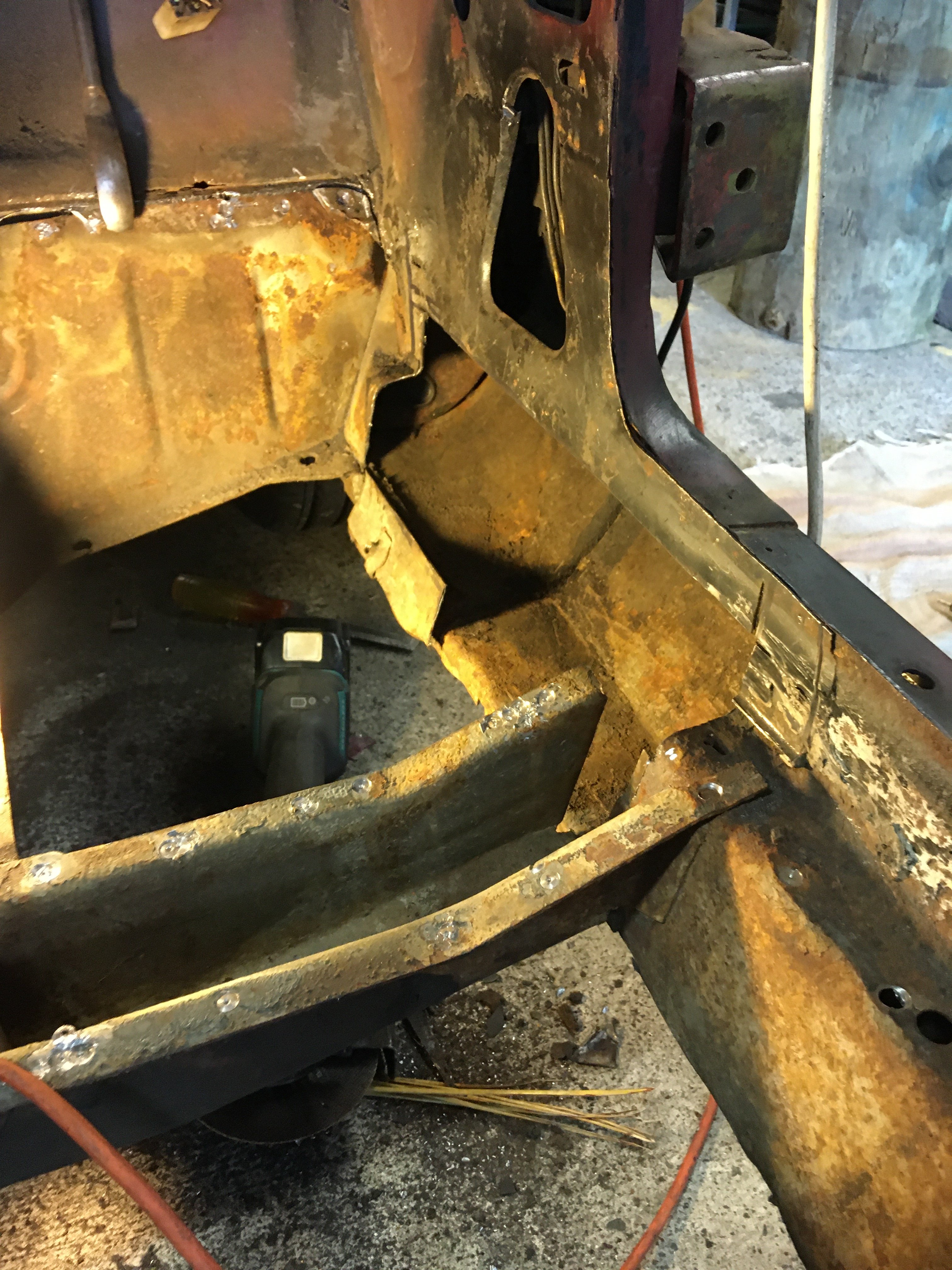
Inner sill almost done will be replacing the top part of the inner door sill amd inner a and b piller after I get the floor in so I can cut out some old repairs .
1 point
-
Free bit of Weekend spent hanging/ aligning the doors, guards, valence and bumper for good. Pretty OK! Sorry the pics are shit, was in a rush. I’ve had this B310 panel-steel chin spoiler for years and finally bit the bullet and decided to run it. I could have gone Camaro style and had it inset, but the ends made problems when it came to mounting. We made the call to chop it, and the ends practically fit the sweep of the valence after all! just used a random number plate to fill the gap (lol) but it works well so I’ll make a bracket. Not finished but you get the idea. I took the 20 degree angle of the indicator to set the spook angle. And the tyres flipped and lathered in tyre shite to help lift the new-tyre scum and release agent Then, started blocking and bogging. Fucking Joy1 point
-
But if they arent pinging gillies tight, then they wont be loud, and people wont know you're cool!1 point
-
On the bright side, it might result in more posts in this thread - and I'm OK with that.1 point


This leaderboard is set to Auckland/GMT+12:00