
Leaderboard


Popular Content
Showing content with the highest reputation on 03/15/24 in Posts
-
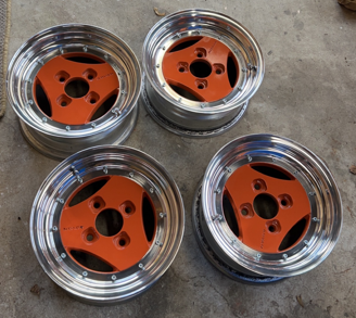
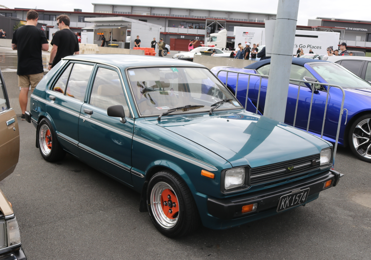
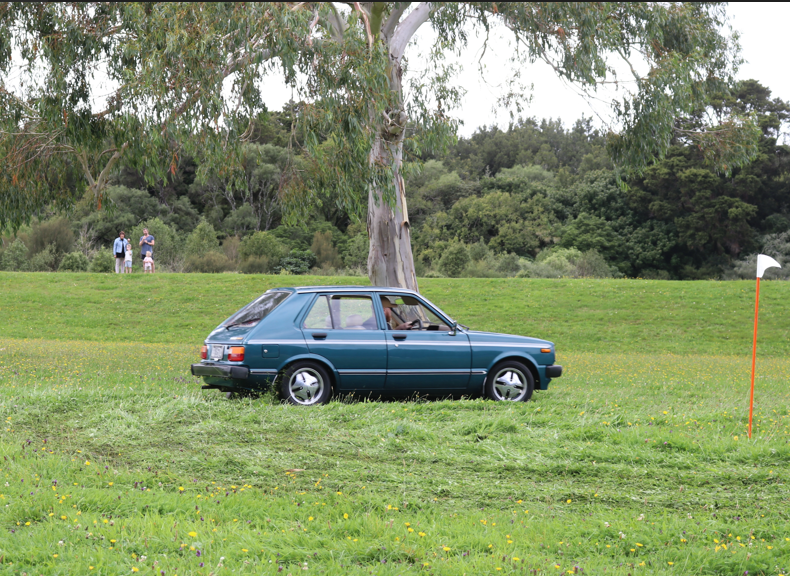
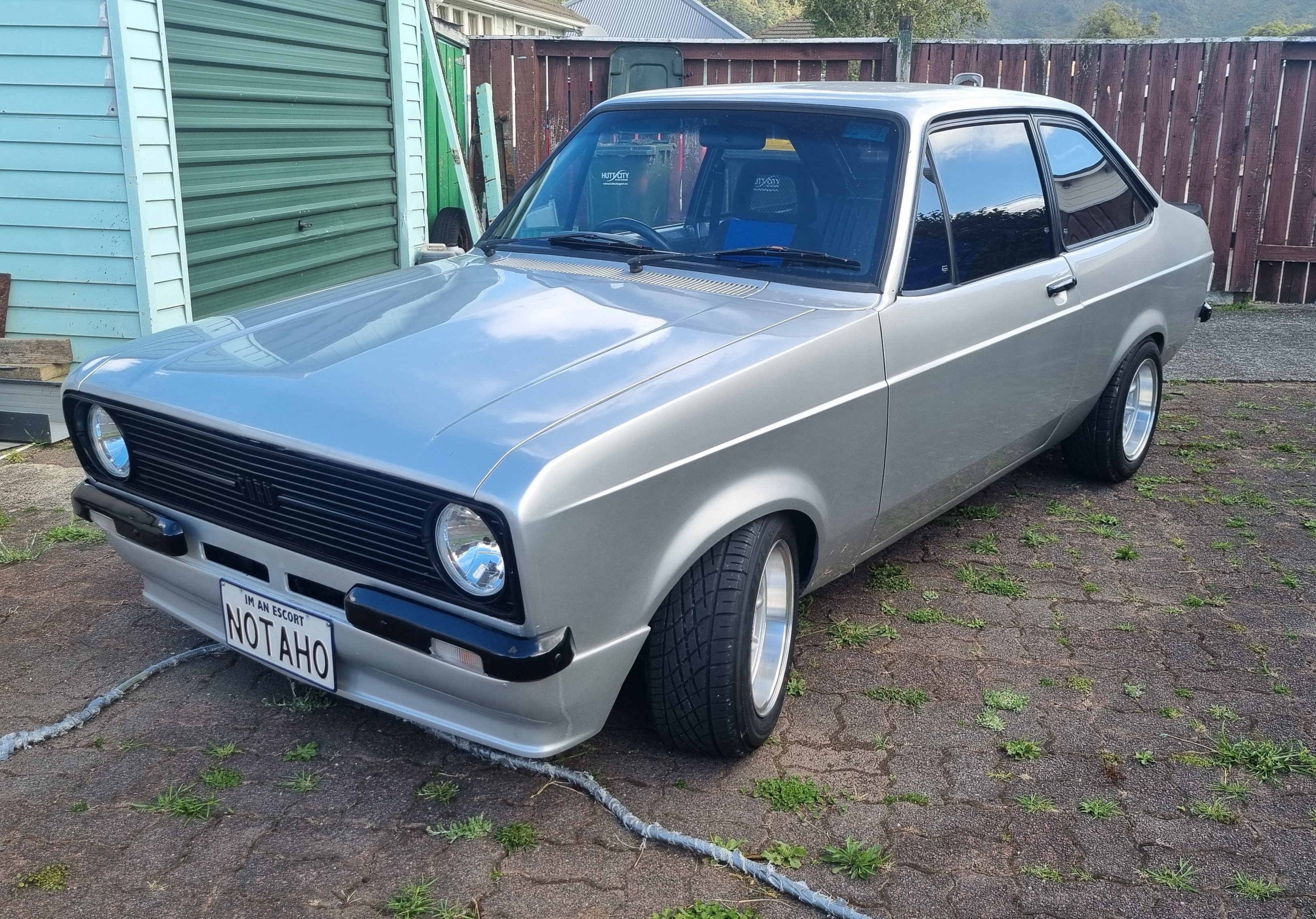
I have always loved Advan A3As and I managed to I pick up a set of 13x6s. I got the lips fixed, painted the centres and convinced the bro to polish them for me (not a member but cheers mate). Orange and blue is a sharp contrast, but it's grown on me Which brings us now back to first sentence of the previous post. I've just driven this from Wellington to Horopito to Toyota Fest at Hampton downs and back (1300 kms) with a couple of mates. There were a couple of small issues with the KP on the trip but those were quickly and easily rectified. It might be slow, but it got there ha } Have a squiz the oldschool.co.nz sticker I got over a decade ago and never used until now. That's all for now
 16 points
 -
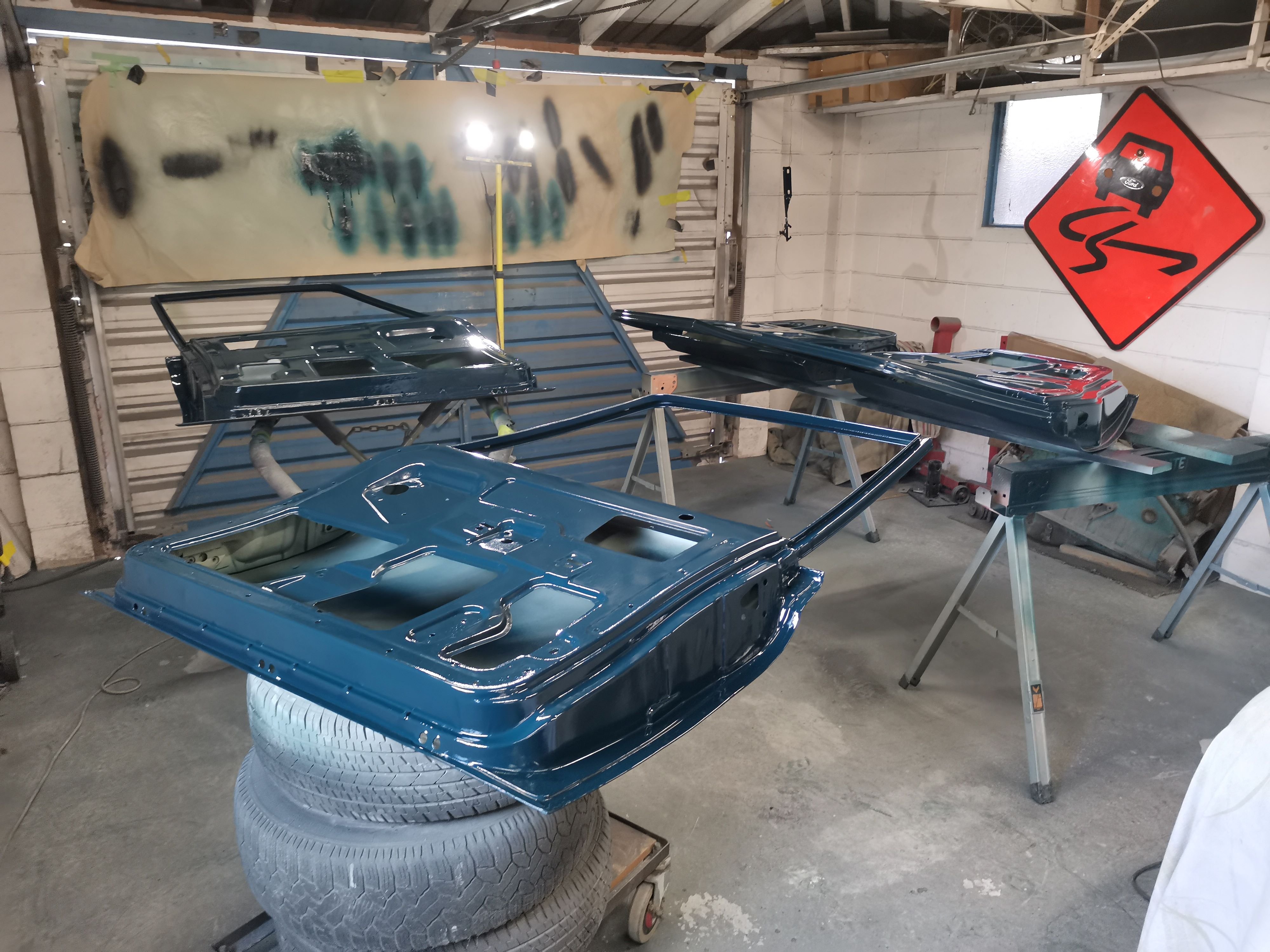
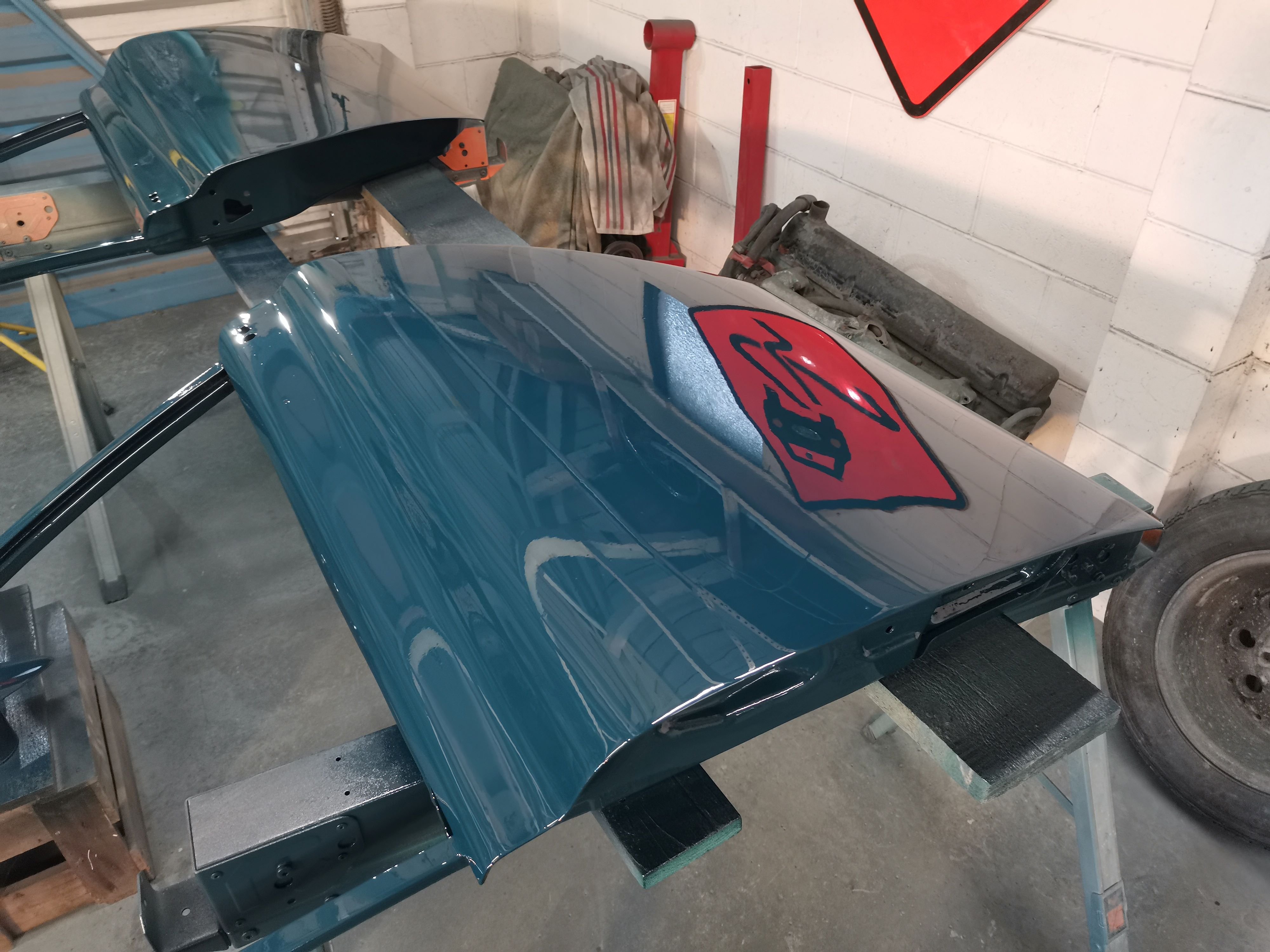
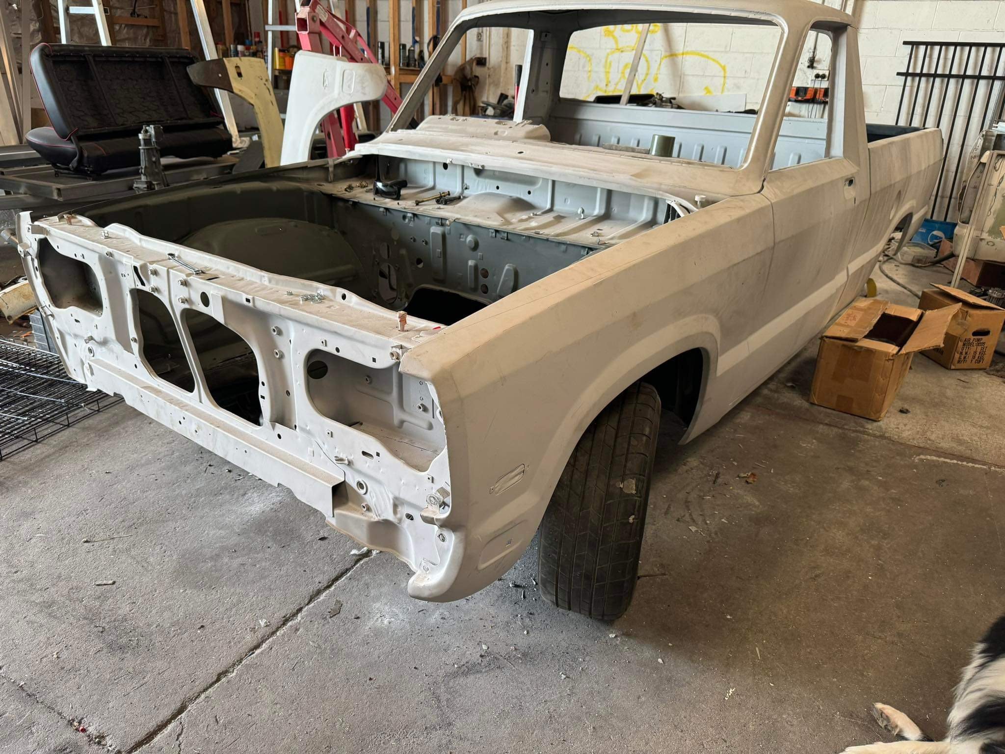
The door with the plasma cutting was pretty wonky, so ended up finding a replacement. Managed to get all of the doors paneled and into paint. A bit of dust and a couple of runs, but I'm definitely getting better with the paint gun. Now working on sandblasting the door hinges and cleaning up the boot lid, before reassembly, wet-dry sanding and a final coat. Stoked to be making some good progress again.
15 points
-
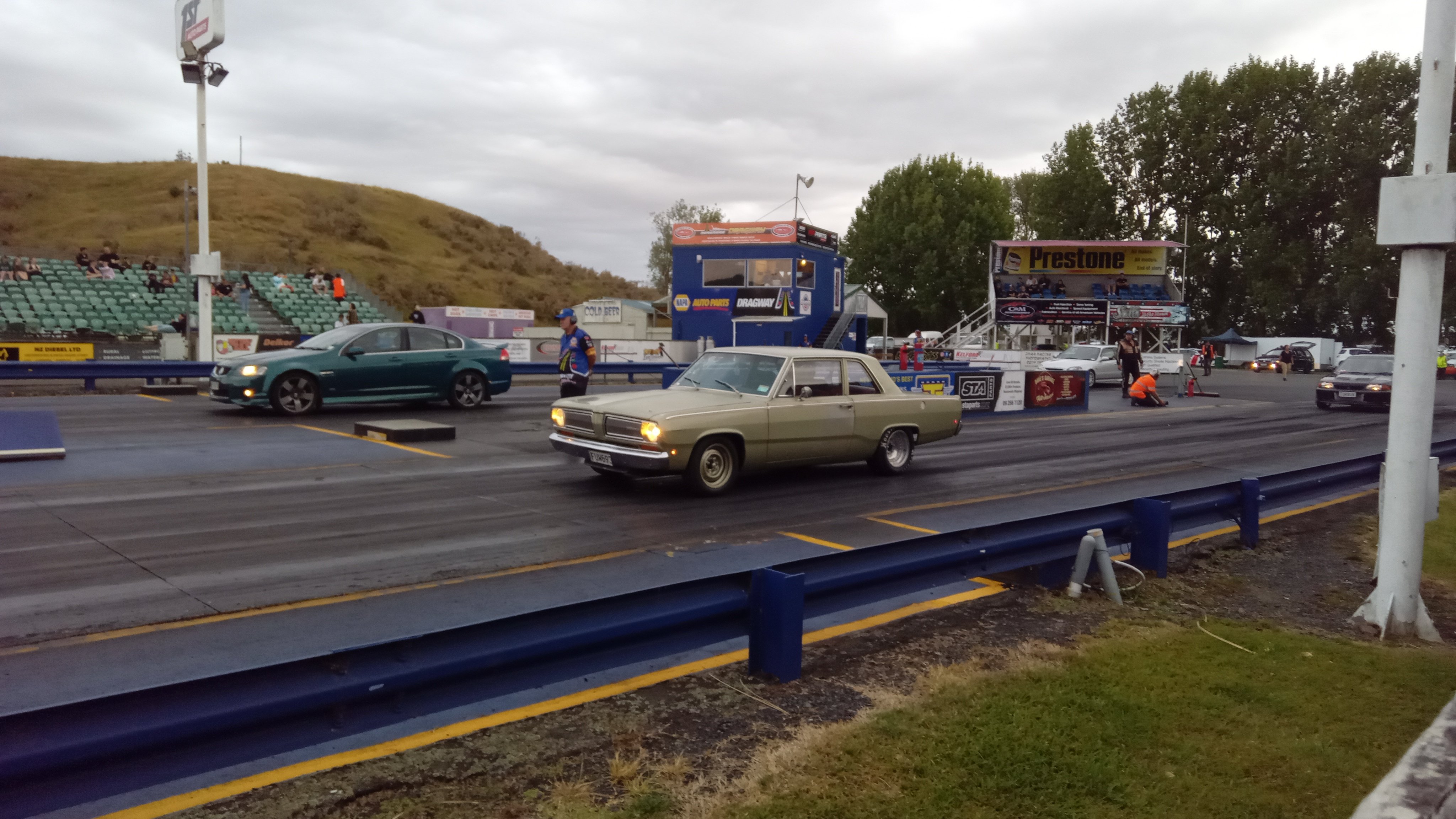
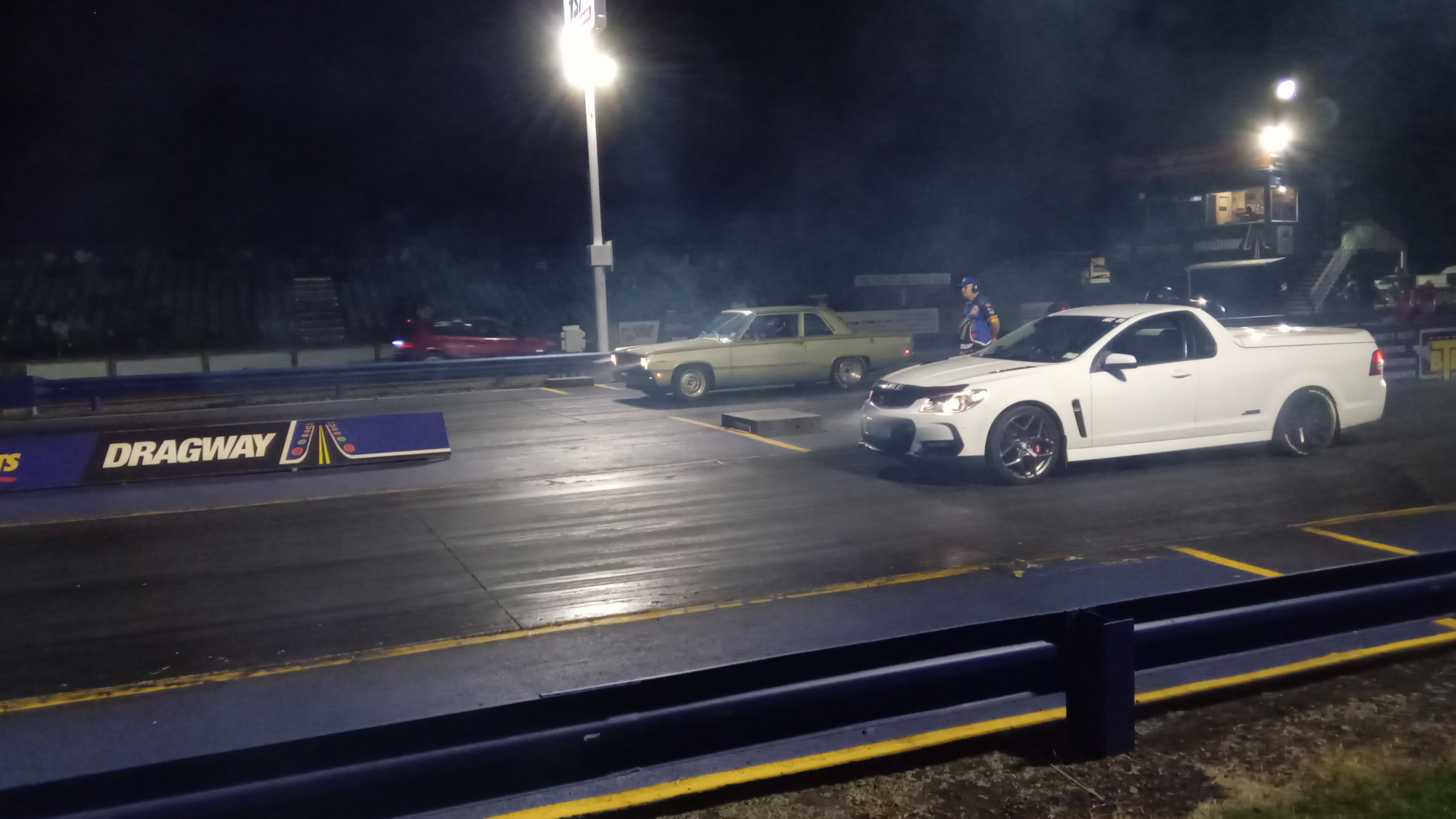
New springs made it more consistent,although slightly slower. Different wheels and muffler off when it did the 11.35 previously 11.5@118 every pass I have turned the 2 step rev limit down slightly as it was having trouble holding on the brake which I can probably fiddle with to improve I'd like to get it down to 11.0 so it's more competitive at the night drags https://m.youtube.com/watch?v=kdfGgT2pKHw&pp=ygUMVW5kZXJjYXJ2aWV3
9 points
-
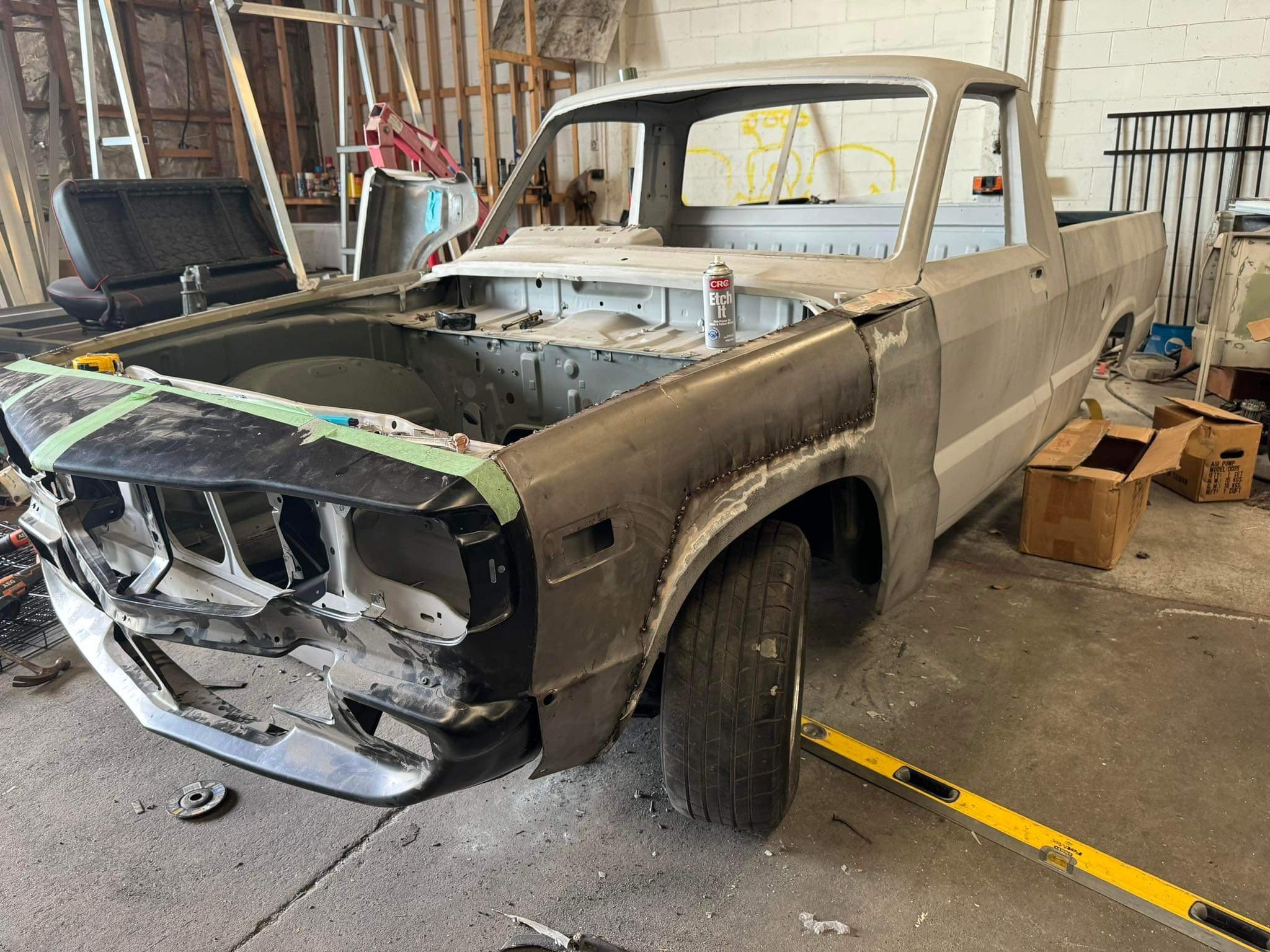
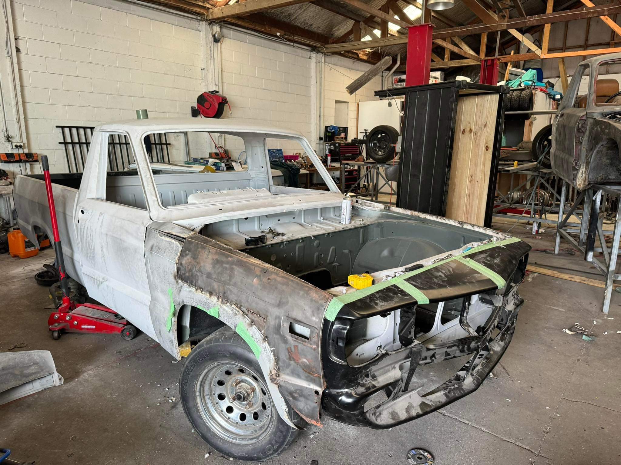
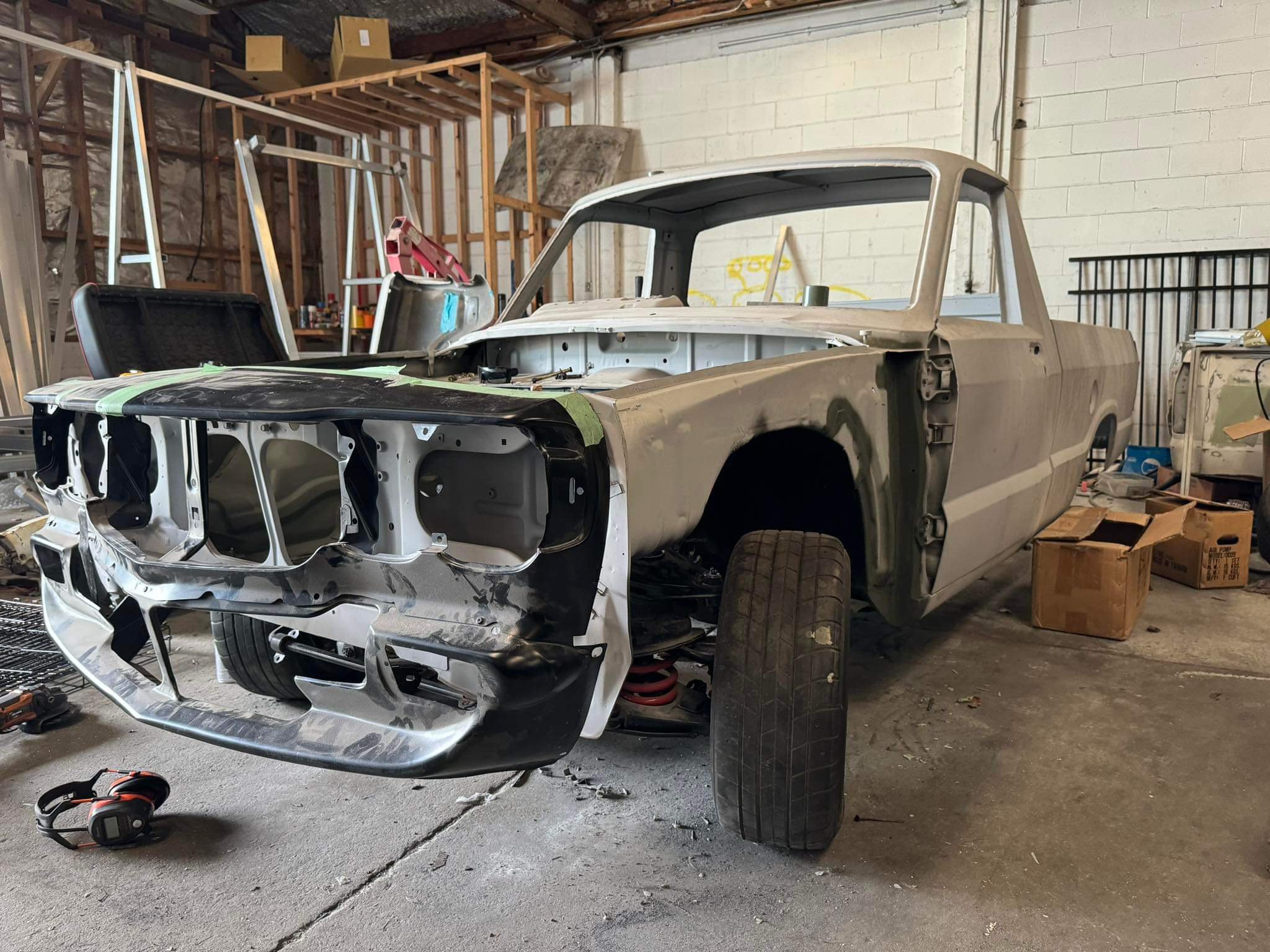
Nosecone is fully mounted, rough guards are on for mock up. this ute seems to be longer than the other ute. Probably built in a different factory as they are 4 years apart from memory.. im glad I chose to use this ute for RX3UTE, it is the same model and spec now.
8 points
-
Big step forward. Rest of the stuff can be drip fed, as and when I feel like doing it.
5 points
-
Regards the driveshafts. I chatted to my hotrod friend, ran the two ideas I had come up with and he suggested an even neater, stronger, failsafe way to do it. But I had to get another pair of scooby shafts because I'd already chopped the ones I had down in length I won't go into details here because I'll spend enough time doing that in the build thread but I'm super happy with the results. As for fuel tank, yeah since I've added a bolt down hatch to place the pump inside is now modified so I'll look for a suitable plastic box* for the battery (it's quite small though) I can't line my alloy box because I made it to suit the battery and it's bloody snug in there. I could line the outside but it would end up messy I bet. *off Alex goes - rummaging through the Sistema range of kitchenware/fuel tank/battery boxes at the warehouse.4 points
-
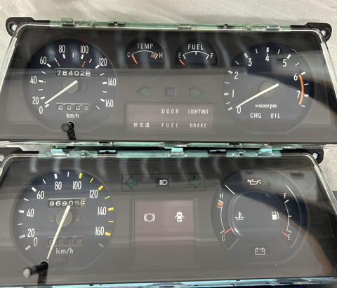
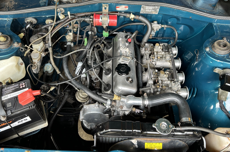
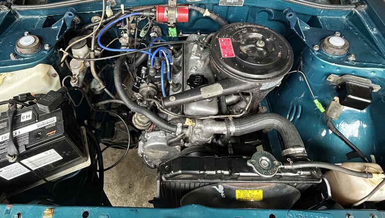
I've just driven this on a 1300 km round trip so I am feeling inspired to talk shit about it but more on that later. Jeepers, it's been a few WOFs since the last post.. I'll sum up the last couple years.. I did a grass auto cross, it was a hoot I changed the cluster for a rev gauge one (shout out to Matt for the wiring diagram. that would have taken me far too long to figure out) The inevitable happened, and the 2k just wasn't cutting it anymore so I started to build a 5k (got a cheap van, drove it home and pulled the motor). While I was building it, a well used 5k came up for sale locally and for what it came with, it was too good of a price not to grab. I gave it a birthday, put that in, blew the head gasket driving home from getting it tuned, replaced the head gasket and then had a few months dorting around. I was told all the classic yarns when I got it.. bored block, ported 3kb head, oversized valves, massive cam, high compression etc. Which surprisingly, were true. Unfortunately the lifter prolapsed. With my tail between my legs I ripped the trusty 2k out from under the house, gave it a spray can rebuild and put it back in place.
3 points
-
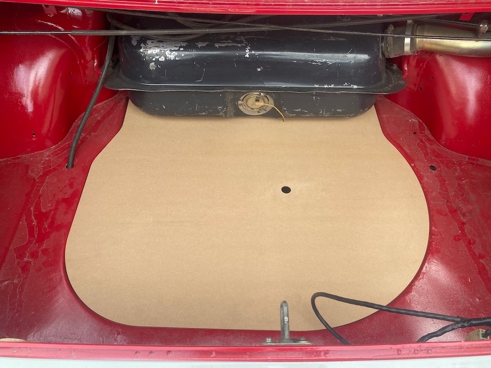
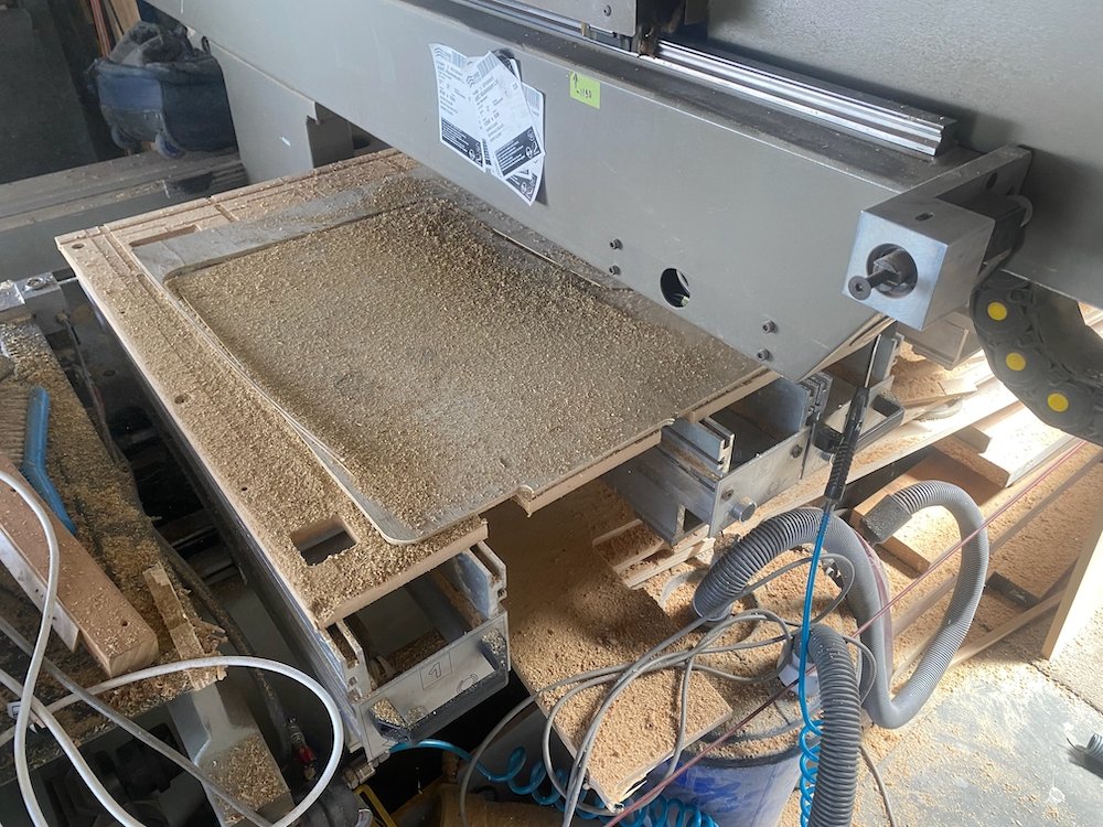
Was out in the shed again today so had a quick measure up and fed the cnc some mdf Quite happy with how much nicer the boot looks with the spare covered, motivates me a bit more to suss some carpet etc. From factory there were a few more trim panels in the boot, hopefully have a set on the way to copy, its something i've never seen before so looking forward to it!
3 points
-
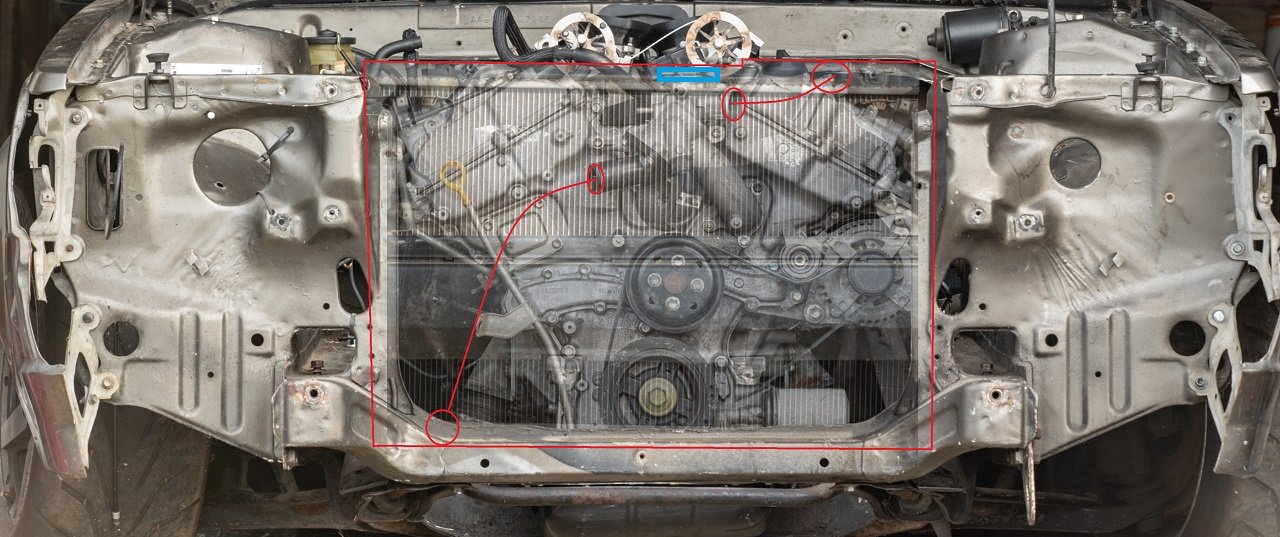
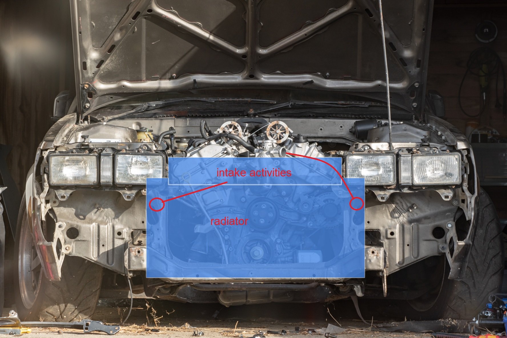
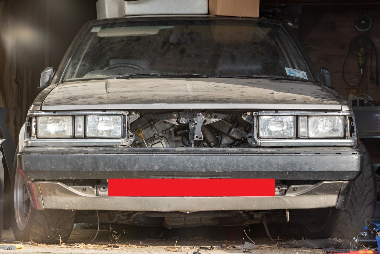
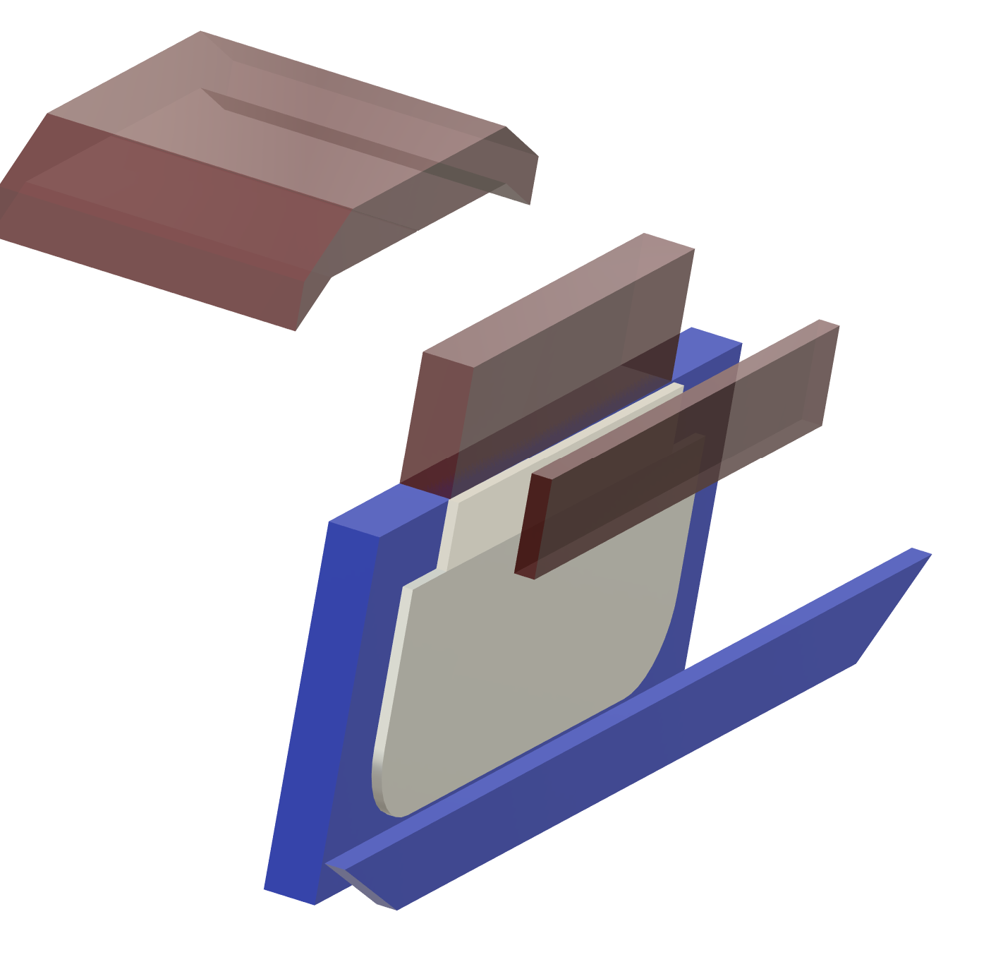
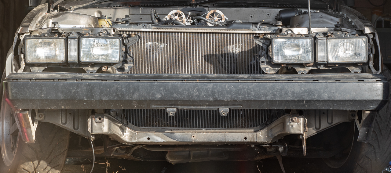
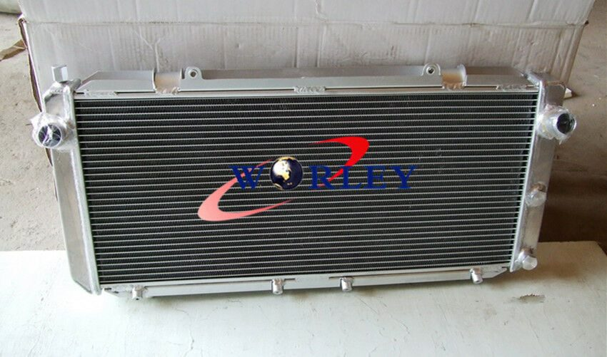
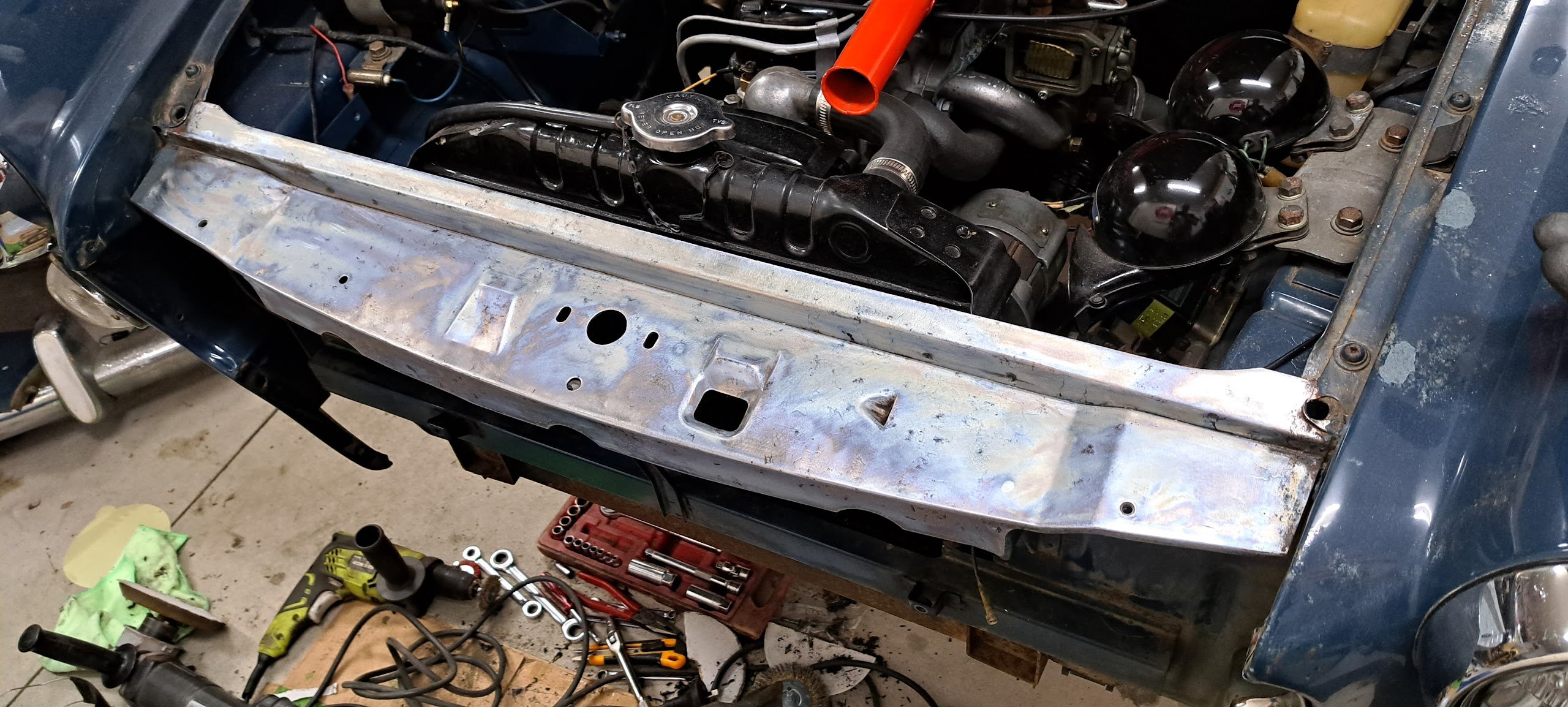
Radiator situation I've got the Mark X radiator in there currently, and although it made everything nice in a lot of ways in the back of my brain I know it's just not going to work quite right. As the top pipe sits too high. You can see it sits a little higher than the top crossmember too, and this isnt on any mounts yet. Just sitting hard against the bottom. The motor's radiator cap (in blue) sits a little lower than the radiator, and the top hose to the radiator flows uphill towards the radiator. All bad news for ever trying to bleed the air out of this thing. Another issue is that I'd love to have a front facing intake airbox that goes through to the front grill, like a lot of the BTCC type cars have. The best option I've found for a low, wide, twin core radiator that doesnt have a radiator cap (and does have an air bleed) is from an SW20 MR2. Being so much shorter, I can dedicate all of the front grill area for the intake. And they're a common upgrade item for MR2s, so cheap and plentiful. The radiator is 5mm wider than my chassis rails, but the end tanks are alloy and on the sides. So will just need a little slice and reweld to fit at the bottom. If I dedicate the top grill to doort noises, then I dont have a huge amount of frontal area for the radiator coming in from just underneath the bumper. Possibly need to remove the bonnet catch as well, but I'd prefer to keep it over having bonnet pins or whatever. This is a rough approximation of how much space I've got for each thing Red is intake stuff, blue radiator stuff, white is the open area that the radiator can get air through. So a lot of the radiator area will be fairly useless if hard mounted against the front of the car, as it wont get any air flow. so I'll try mount it as far back as I can towards the engine. All of this stuff is a bit off topic to my path towards getting the engine fired up, but I've been working on that too. Last night cut the fuel rails a bit shorter, so there's more room at the back. for the fuel dampers without hitting the body. Then also had the underside of the rails milled down so the throttle linkages dont hit the rail anymore. So that's just about all finished once I've retapped the ends and remade the AN lines to suit.
3 points
-
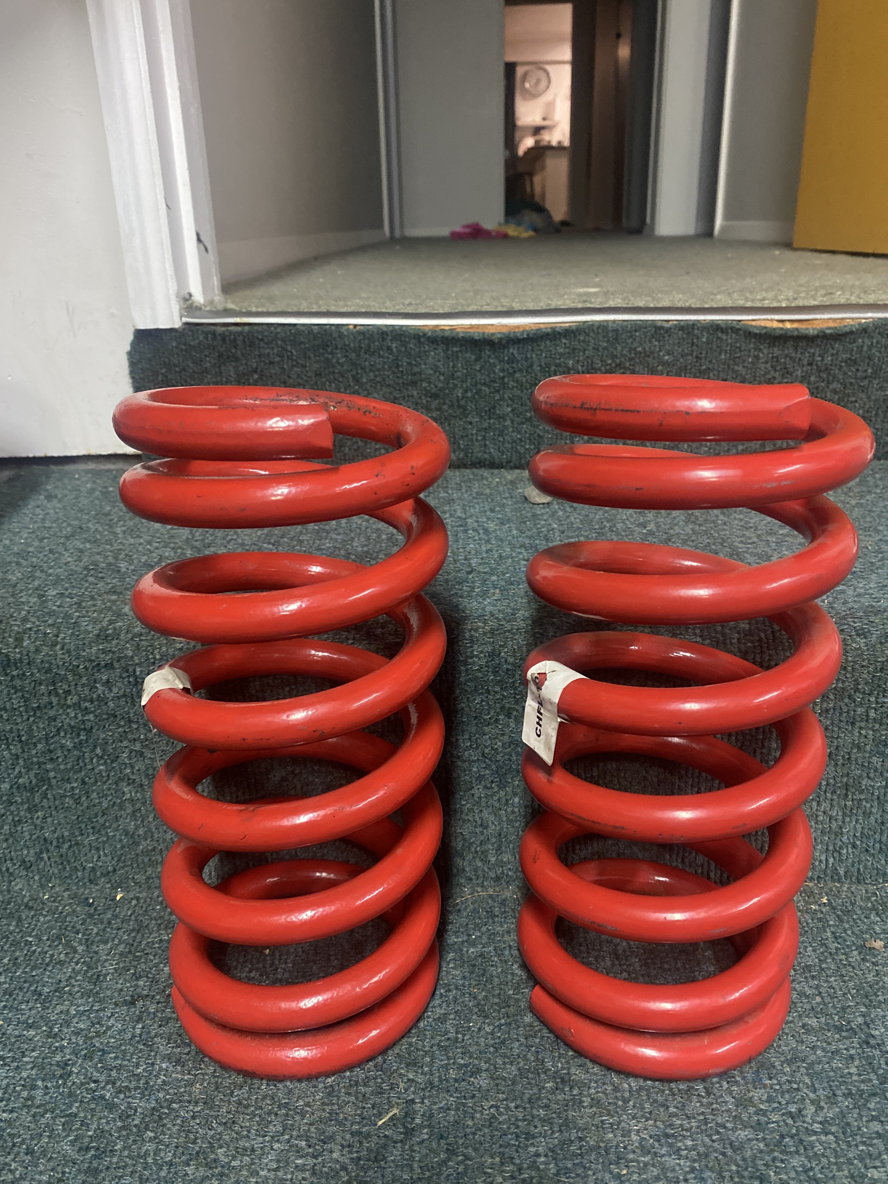
I’m stumped. so I’ve sorted all the dust boots, reassembled to what I thought would be exactly the same set up. But no the passenger side assemble sits lower than the drivers side. (I finger space vs 2). pulled apart again as I read potentially have left and right spring around wrong way…pulled springs and shocks out but I’m dammed if I can tell ‘em apart. springs are HQ 6cyl with identical markings. Spring perch is the same. Would camber spaces/shims have anything to do with it? now that I’ve looked at the dam things so long I can’t remember which one was in the left or right.
2 points
-
All legal beagle, any cruises etc hmu,will head upto cars in coffee, few things to do still but that's any car really, needs gearbox badly and decide on a new engine, time to give her a beating
2 points
-
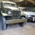
Watched Patton last night, keen for some more tanks.2 points
-
Would I use a full size broom or a 1/35th scale one ?2 points
-
It looks like they are asking you to check if the play is within manufacturer specs Ie they don't want to make a decision themselves2 points
-
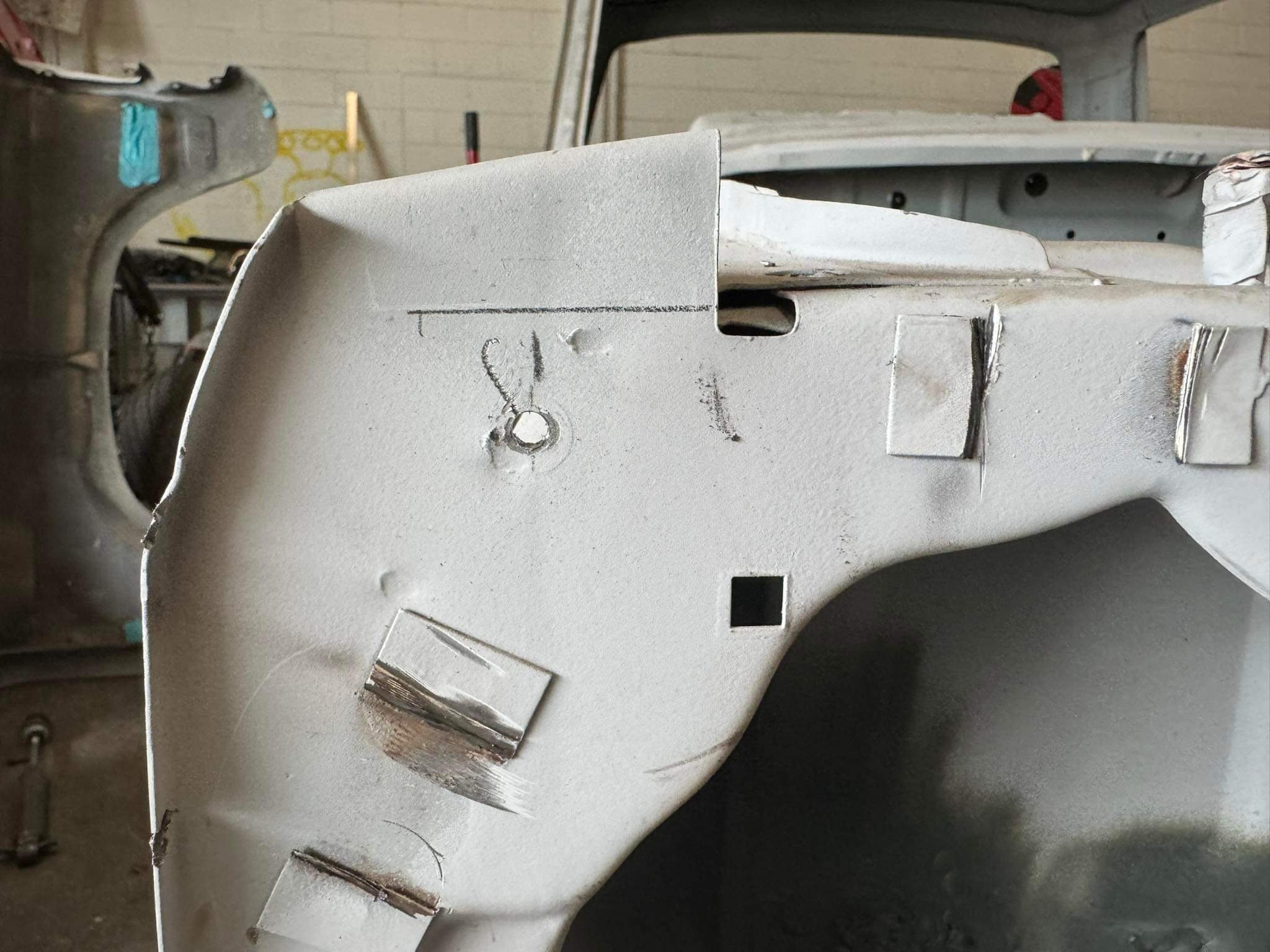
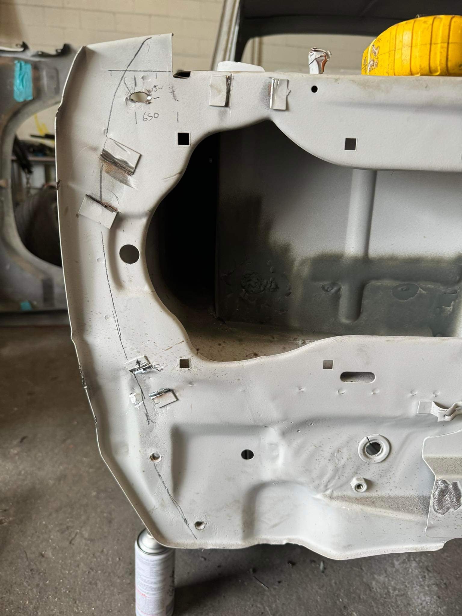
It takes a special kind of idiot to take a perfectly good, freshly panelled car, and chop it to bits. boy I need help Cut all the things!!!!!
2 points
-
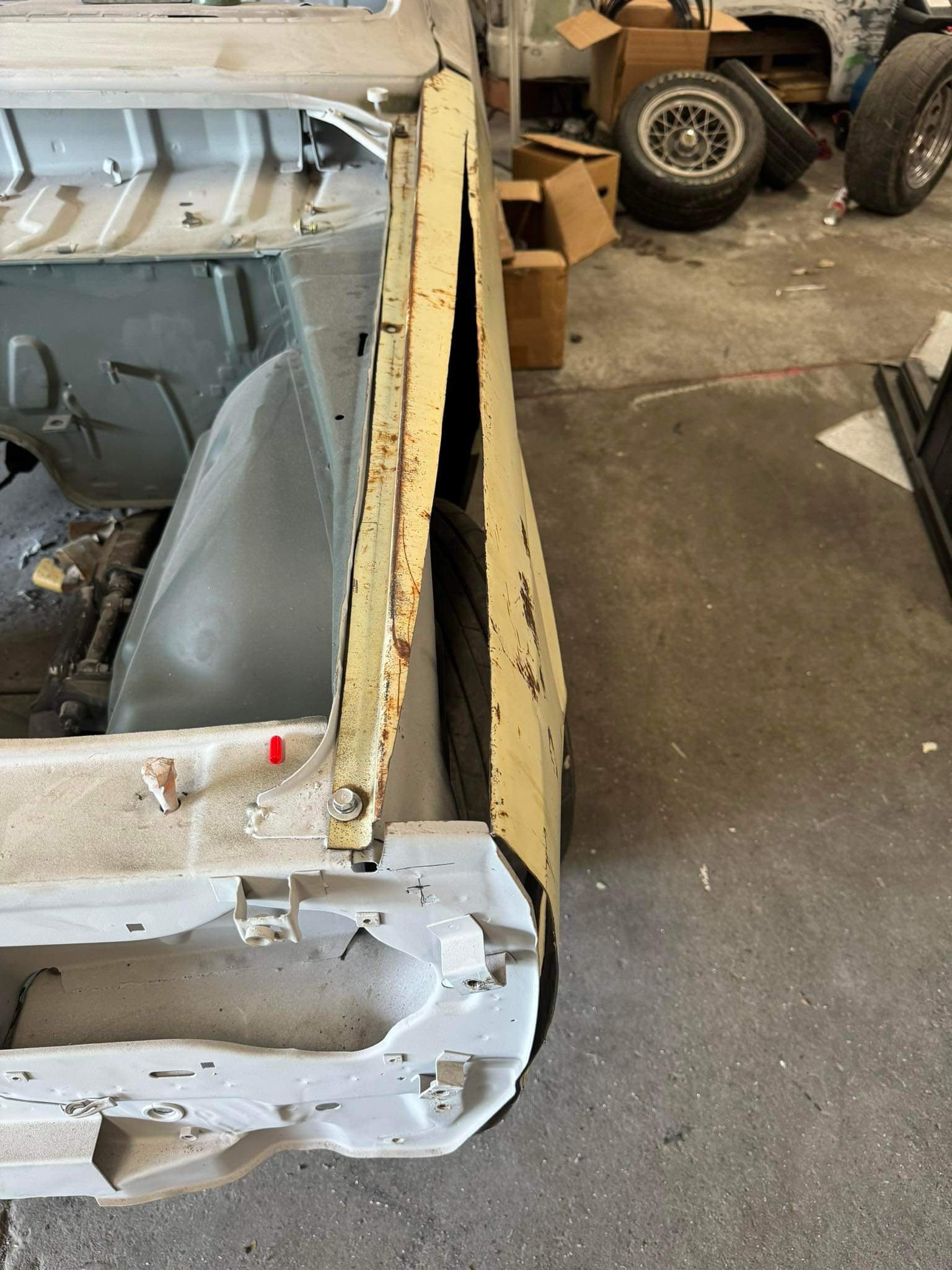
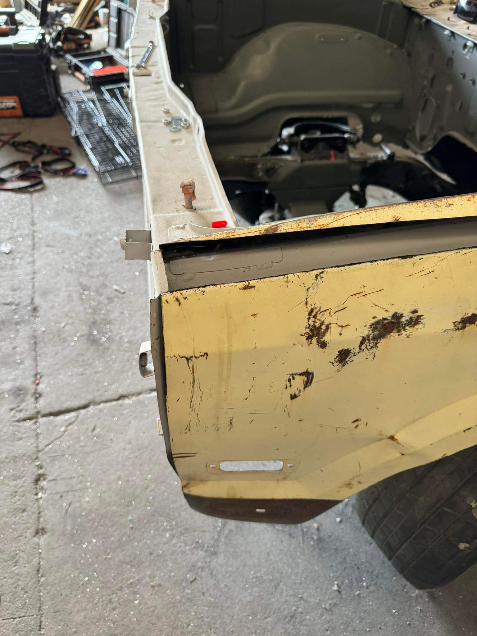
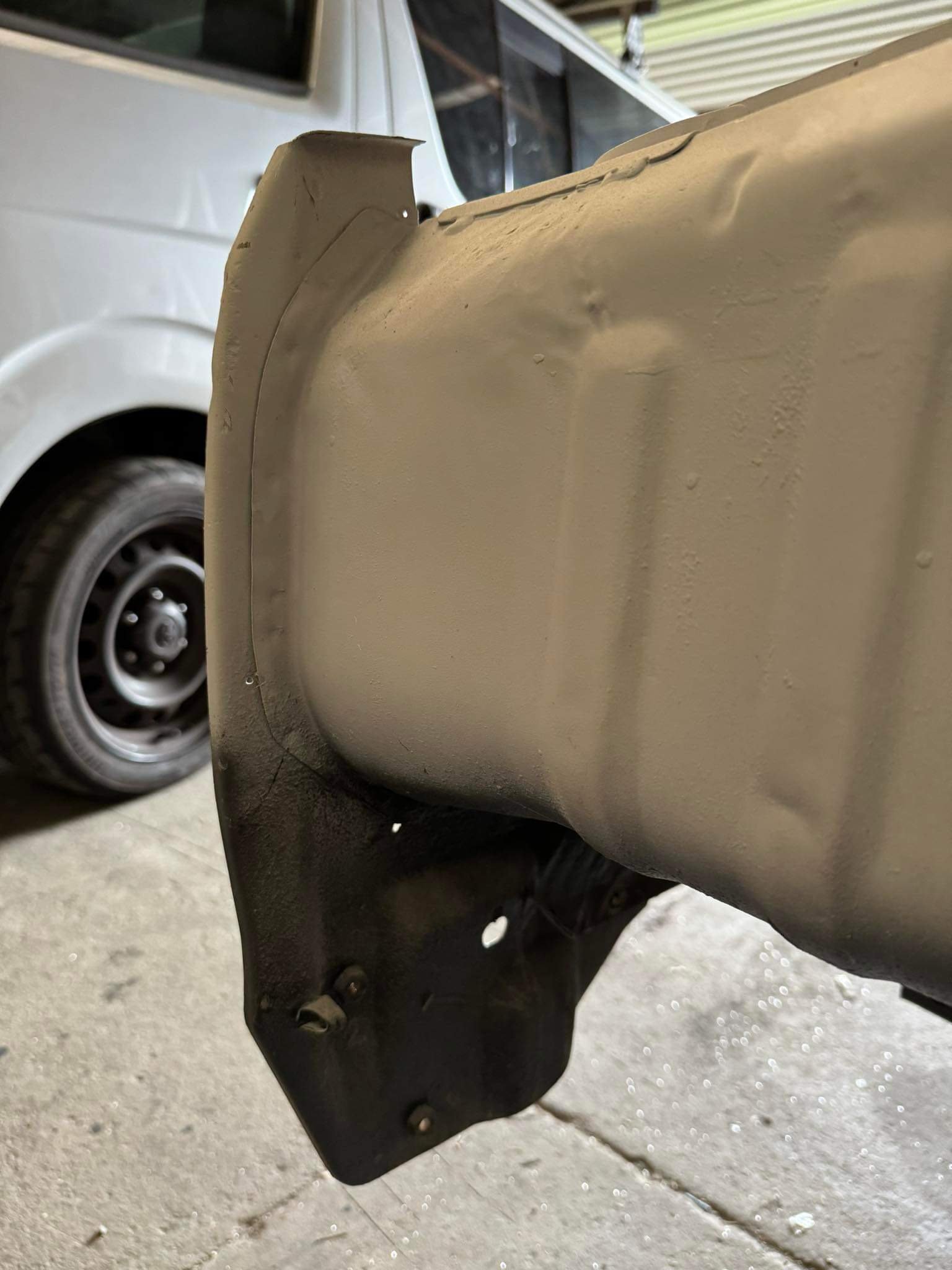
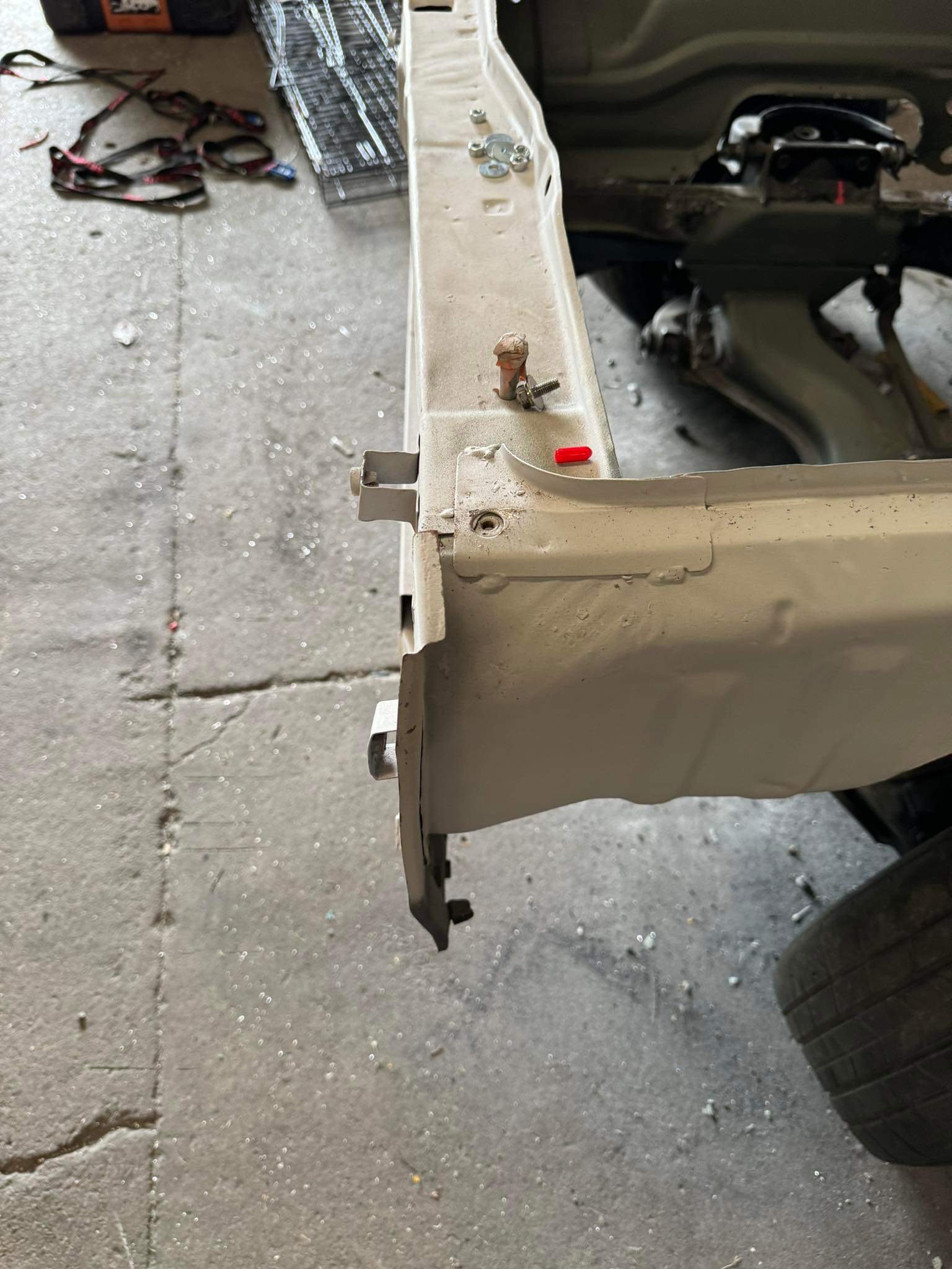
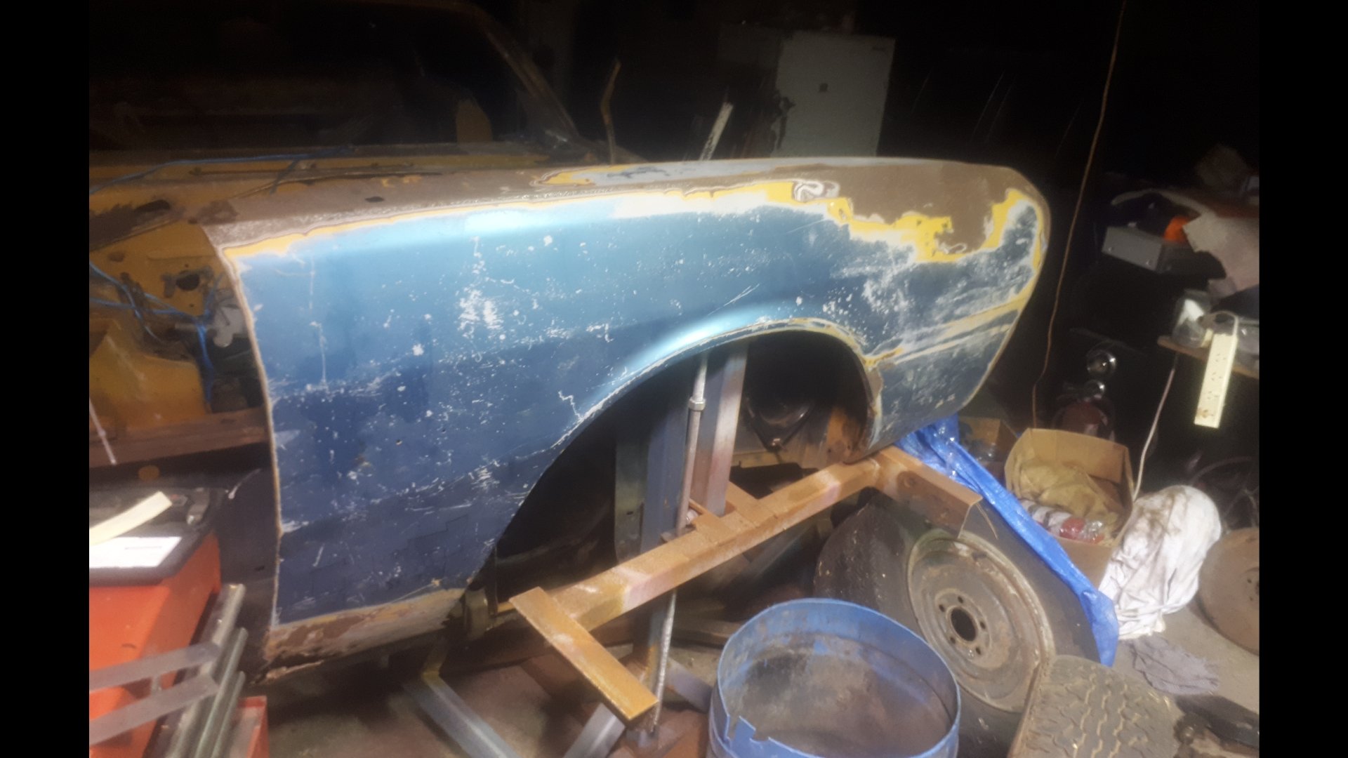
Im still thinking about this once in a while. Tracked down a less fucked right front guard. It was up welles ways. @Goat kindly let me use his house as a freight forward depot. The seller dropped it off, and a mate who was passing by collected it the next day. Picked it up tonight. Defo needs a wee bit of work. But i can buy the inner and outer bottoms off the shelf from Automotive Panel Craft in Oz. Thanks to @Classicdat for lugging it south for me too!
2 points
-
I modelled and printed some door card clips which as always gives me the deepest pleasure. These worked pretty well after some tweaks. These are not exact copies and are designed so they are easier to print, but functionally they are sweet. The drivers side window winder mech was deeply wrong, the wire tension adjustment was maxed out, hacked and the maxed out again, but the wire was still as loose as fuck and while it kindof worked it made horrible grindy noises. This came from the barrel where the wire was straddling grooves cos it was so loose. It was all down in a difficult to reach place, and those mechanisms are notoriously cunty to pull out and put back. Amazing that I got a bollock into that shot as well. The passenger side was sweet and the wire connection looks like this; After a bit of thought and dicking around trying to take slack out of the wire a genius idea came to me; I routed the wire like that through both lift points, which took up enough slack that I could tension the mech properly. Another 1/4 hr of contortion with a torch, phone and screwdriver and I had the wire slipped back into its rightful track. It works perfectly again, yay!2 points
-
@30DegreesRetarded did you buy the springs new? They often need 500kms or so to settle . also the longer one will go on the driver's side . Because most cars get driven with only a driver so the perch the drivers side a wee bit higher to stop it sagging immediately trim thr bumpstops if there is enough travel in the shock only. Otherwise your shock will become the bumpstop and that's not good lol.1 point
-
So chipping away I've found that having the options to sand blast the nooks n crannys works well and reduces the amount of dust and sand everywhere. On surfaces with underseal the petrol and rag method seems to be most effective. Followed by wire wheel or strip disk. I've started to tackle drivers real wheel well in this episode.
1 point
-
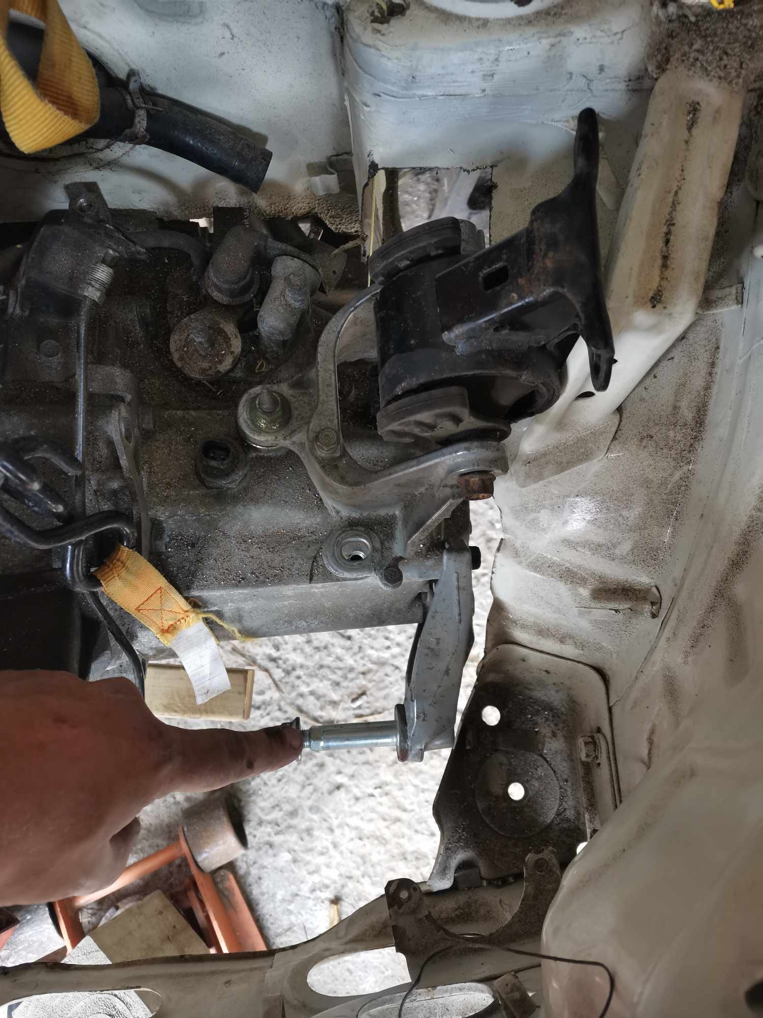
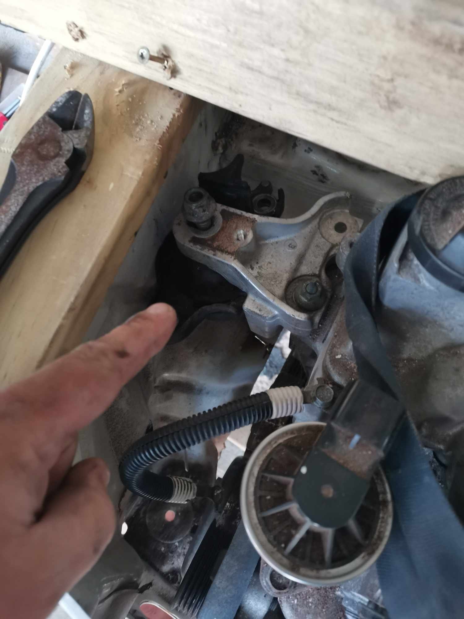
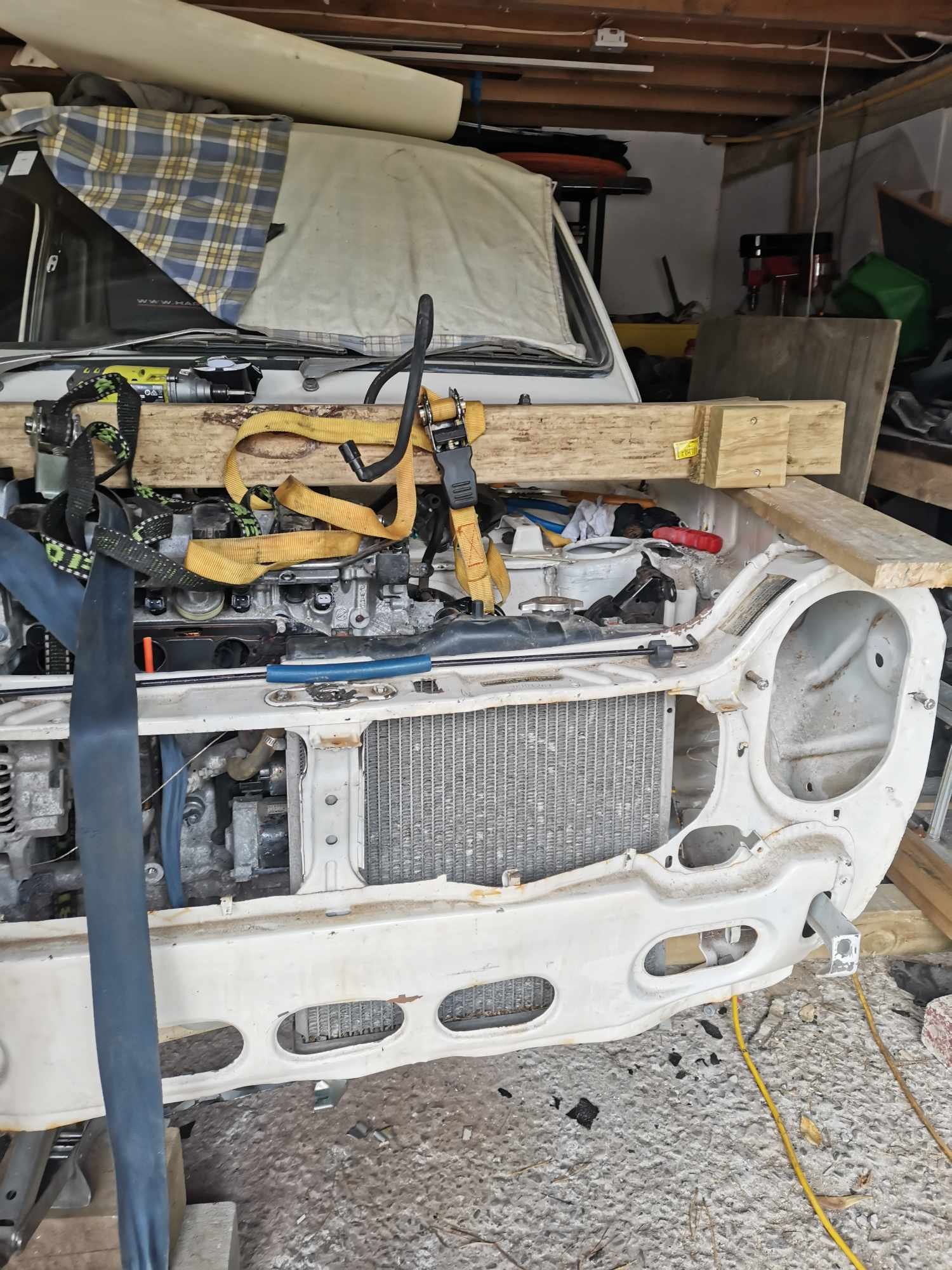
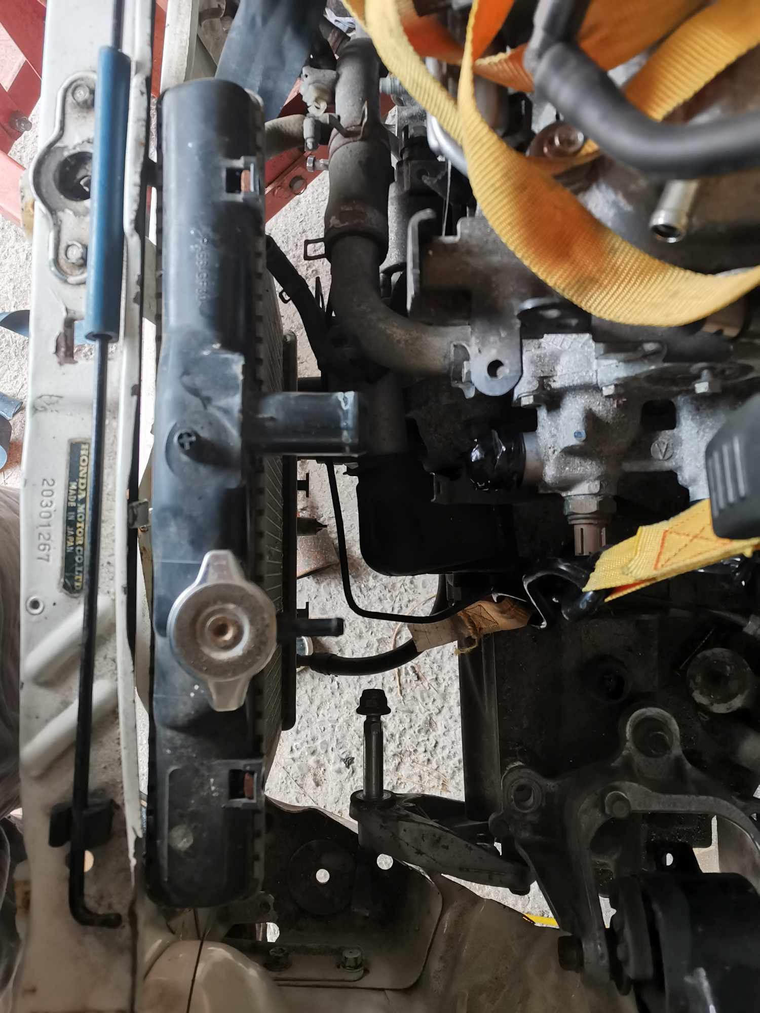
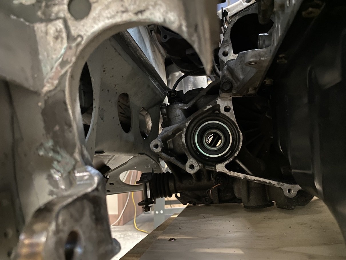
Fitting on factory mounts to see where they kinda land. Gearbox mount mostly fits. The mounting to the box bracket needs to be spaced up 20mm at least. Lots left on threads This bracket is reversed 180, used to point outwards, but this solution looks promising for a front mount Engine side looks half OK, needs a little clearancing with Mr hammer, might look for other options though. EG civic half size seems to fit vertically. Outlets ideally need flipping. Top needs to be to the bottom of the picture and bottom needs to be in the middle. Wondering if I can flip an alloy radiator and swap the fill neck... Hole in strut tower temp drilled so I can line up the evuk 7 shock on passenger side. Next up is steering rack, passenger knuckle and maybe drive shafts? Still keen if someone wants to come have a nosey in Wellington, I'm quite over my head here but continuing on regardless Discust below, https://oldschool.co.nz/index.php?/topic/49007-sirges-1972-honda-n360/
1 point
-
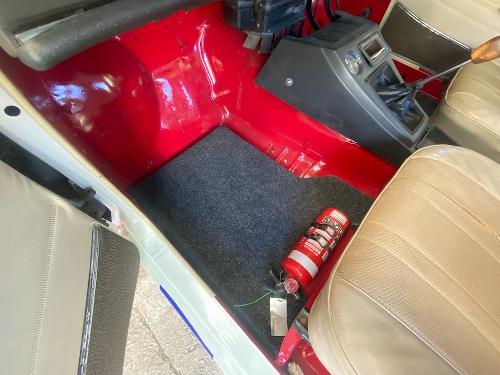
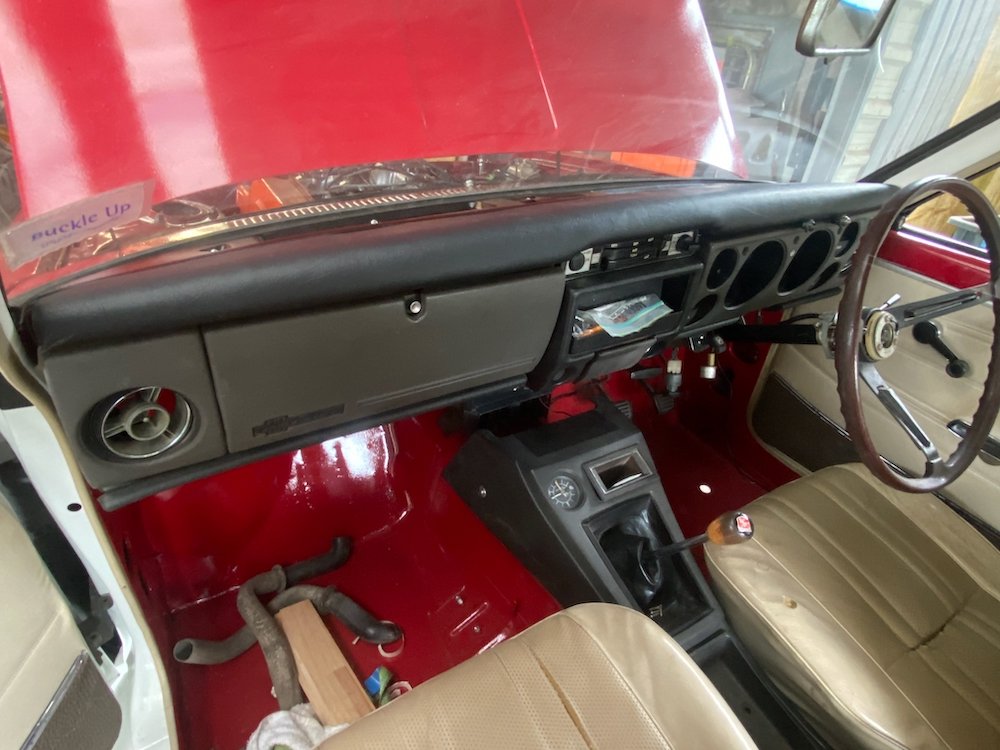
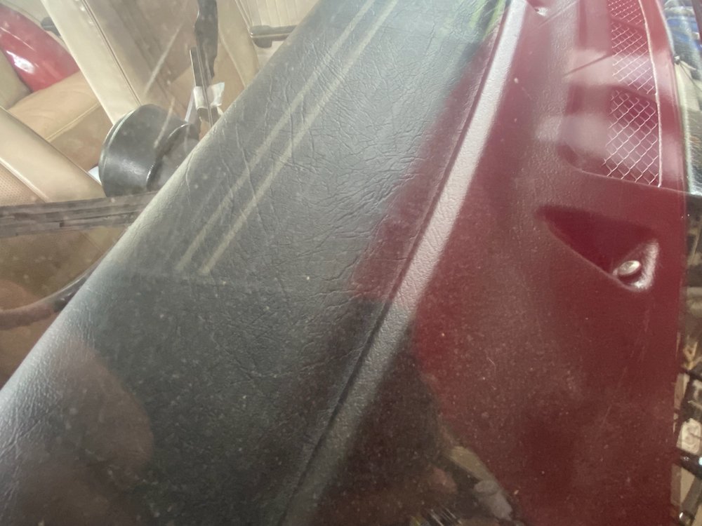
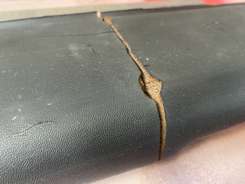
Interior polishing: Like most 50yo cars, the dashpad had cracked up pretty bad, long term i'd like to throw the check book at it, but in a budget friendly manner I called on my lovely GF and her knowledge of spotlight. We trimmed off the worst highpoints and double sided taped a layer of tablecloth liner to the pad, the idea here was the padding would hide the worst of the cracking once the vinyl leather was stretched over This was put on with the bare minimum of contact adhesive to keep the dashpad in close to original shape if needed for proper restoration further down the track. Finish result blends in well, of course the corners are a bit messy, but far nicer to look at than the old pad. Haven't been able to make a firm decision on the carpets but had an idea Chomp out some 7mm marine ply on the cnc, wrap in carpet offcuts from the 4wd.... Floormats that don't shuffle around.
1 point
-
Axle shortening or joining, if it's just an axle, should be fine if it's done well and with a suitable weld process etc, take notes of what you do, what filler rods etc The exception to this is jag rear ends, this is because the driveshaft is the top suspension arm. These need a more specialized process because a failure would likely be way more badderer Battery- if your fuel system is modified then the CCM requirements apply, so battery has to be isolated from fuel in a non conductive box. I have had a customer with a stainless battery box who didn't want to change it, line the inside of the box with rubber sheet so it was no longer conductive between the battery and everything else1 point
-
Won't that come down to if it's a modified production vehicle or a scratch built? If modified but you haven't changed the fuel tank or battery from production then it's fine. As soon as you start modifying anything then all the rules in that section of the manual seem to apply. That's how it seems to work to me but I read it through a vintage car lens. A lot of vintage cars have their fuel tanks scuttle mounted right next to a battery in the engine bay. Mine has both in the tail. The manual talks a lot about compartments which doesn't really apply to some vintage cars. Mine is basically a metal tube on a chassis. For a scratch built historic replica the rules get a bit odd since if you had to follow them all you end up something with is neither historic, nor a replica! This is recognised, and called out in some of the Info sheets (#01-2008 mainly). So I try to keep everything as factory original as possible. Simon1 point
-
im keen to see what you do here re half shafts, its the bane of fwd engine/gearbox swaps unless you have a lego parts bin. I seem to recall something about a splice to be welded but was ages ago i looked and outside my skill level/found some lego instead. You can also employ this when you put the sr20ve 20v with sr16ve gearbox in your k11 if nissan lego doesnt work1 point
-
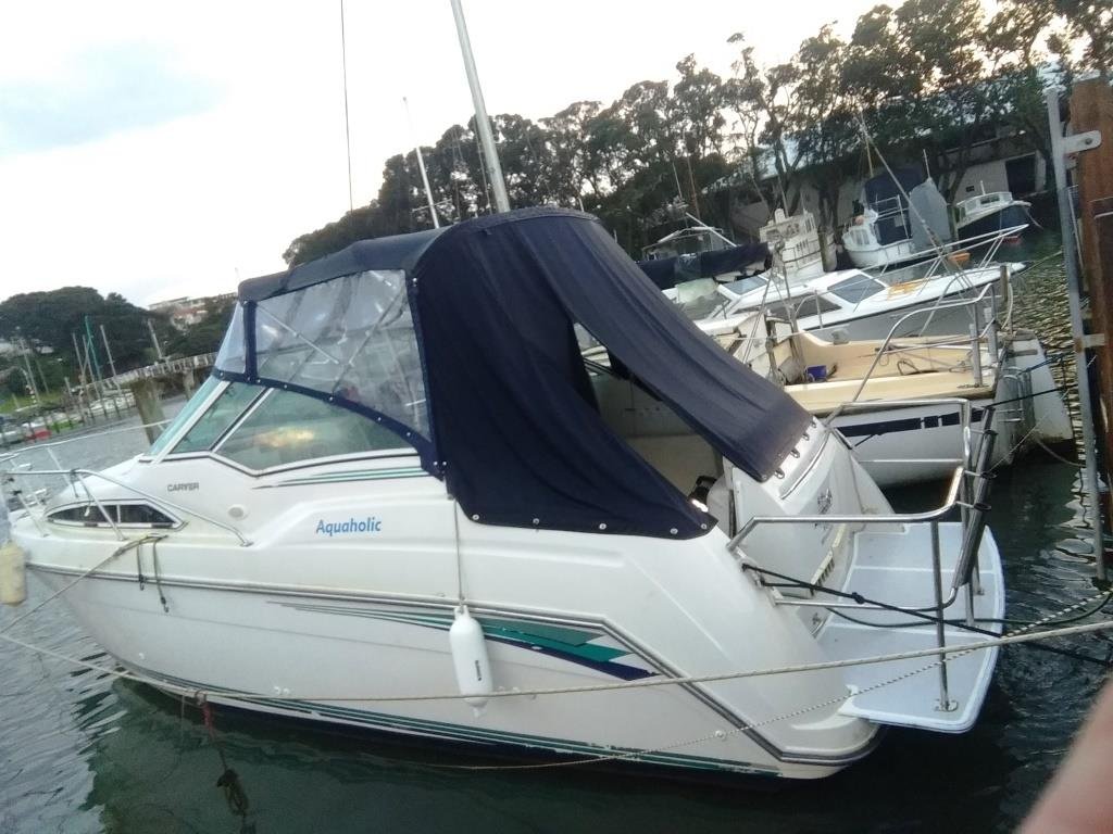
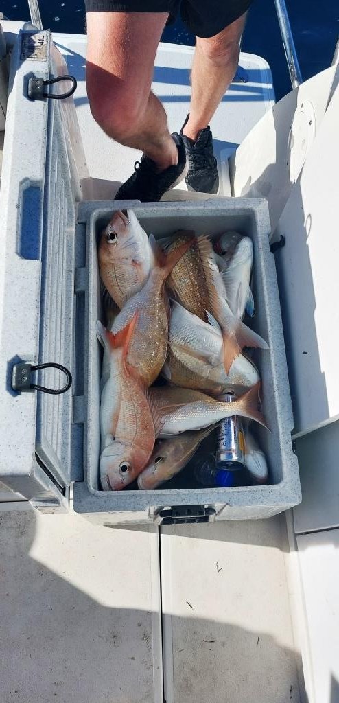
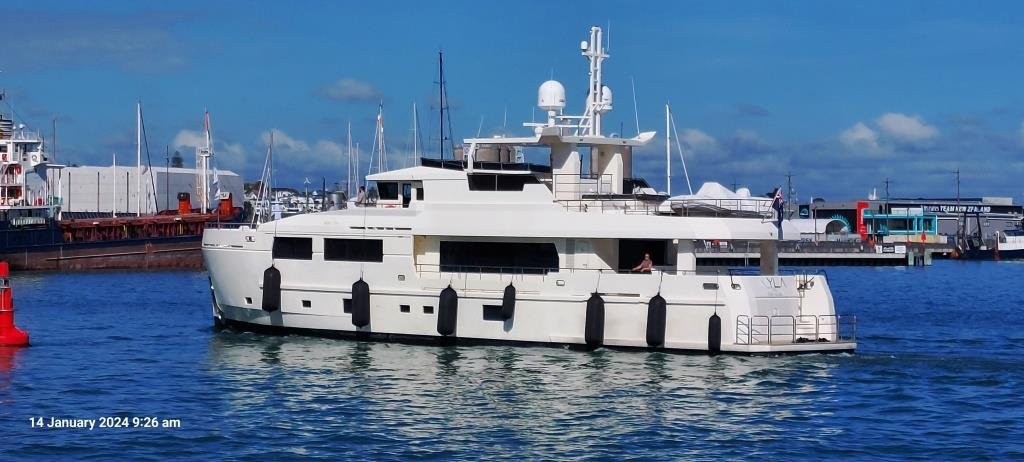
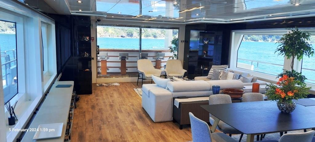
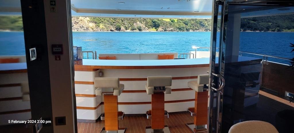
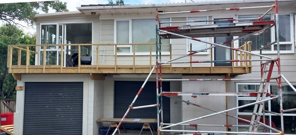
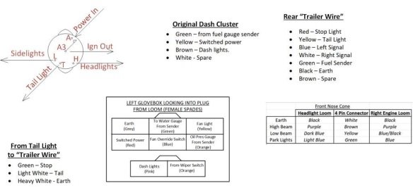
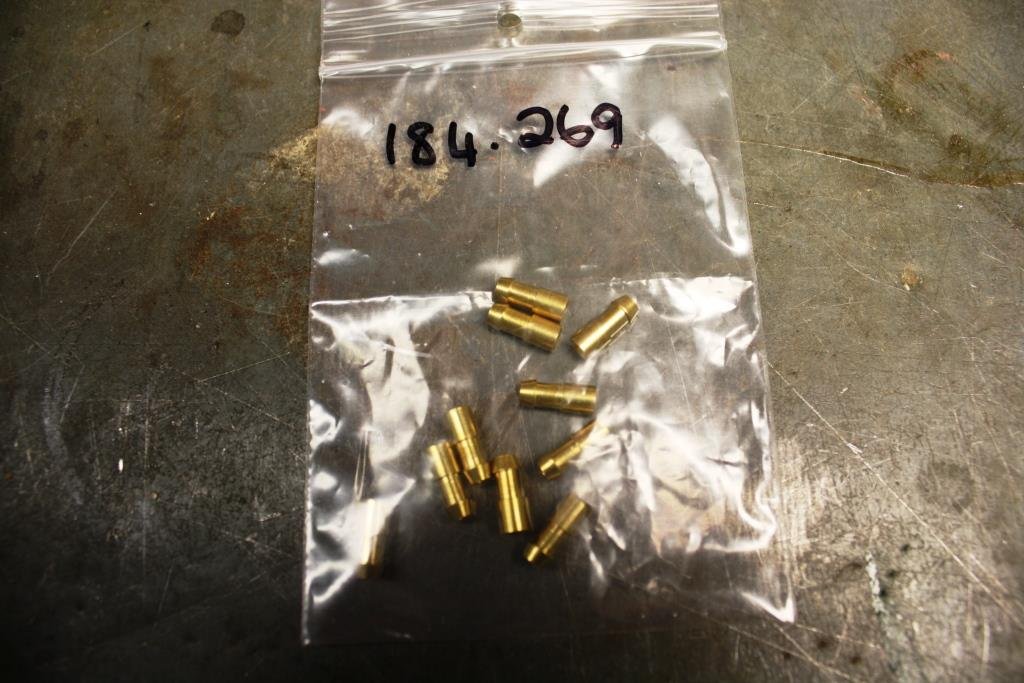
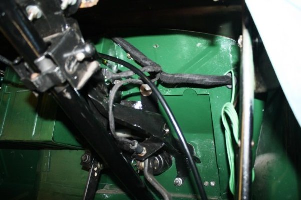
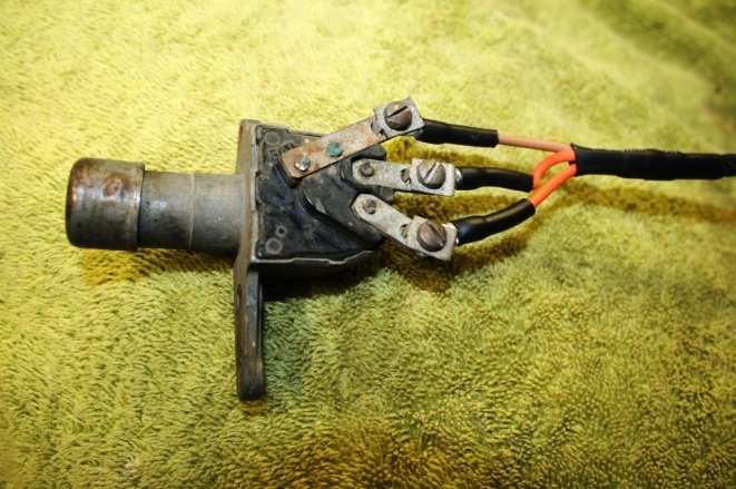
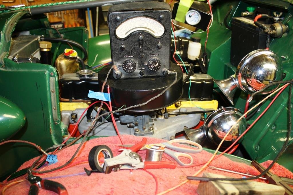
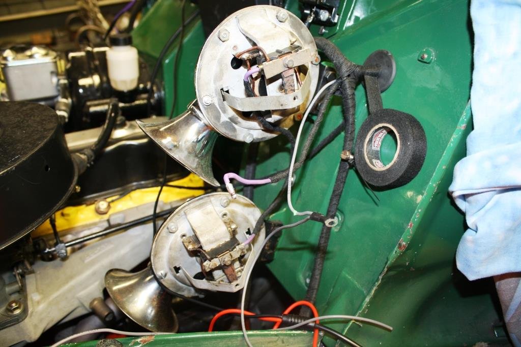
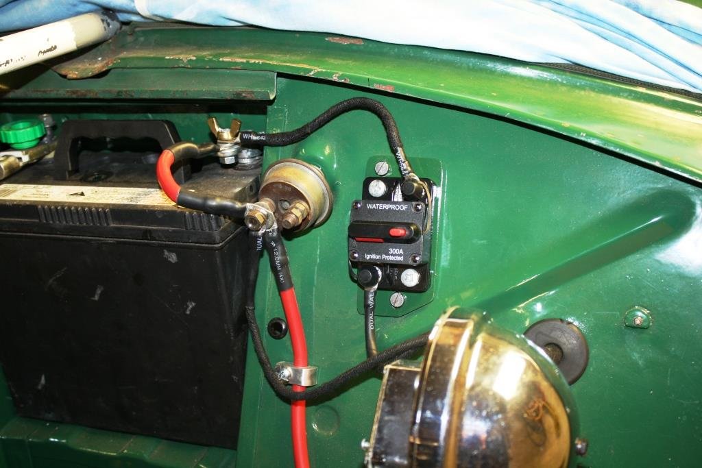
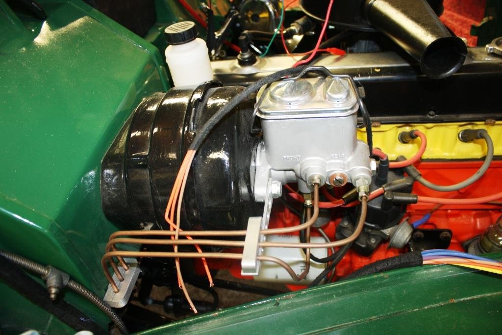
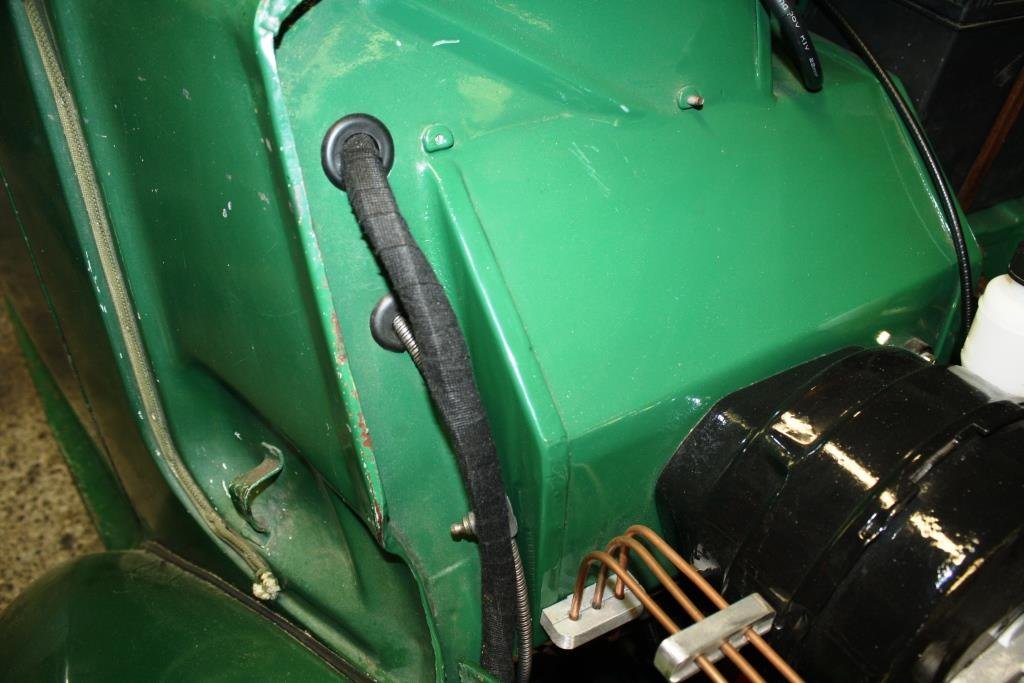
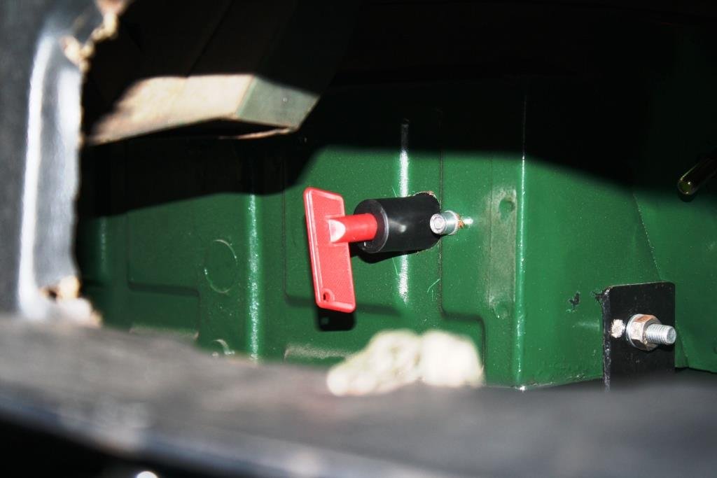
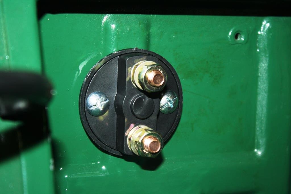
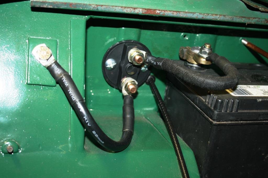
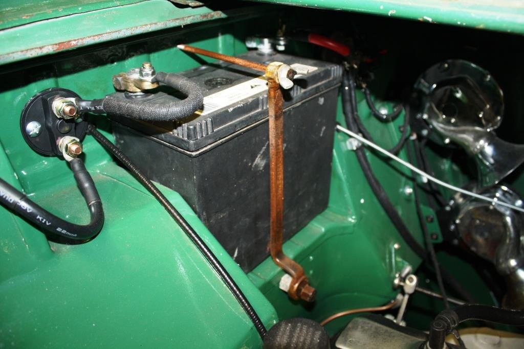
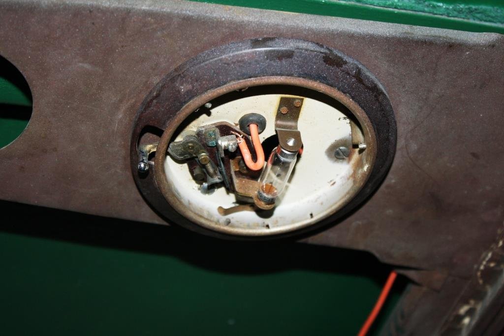
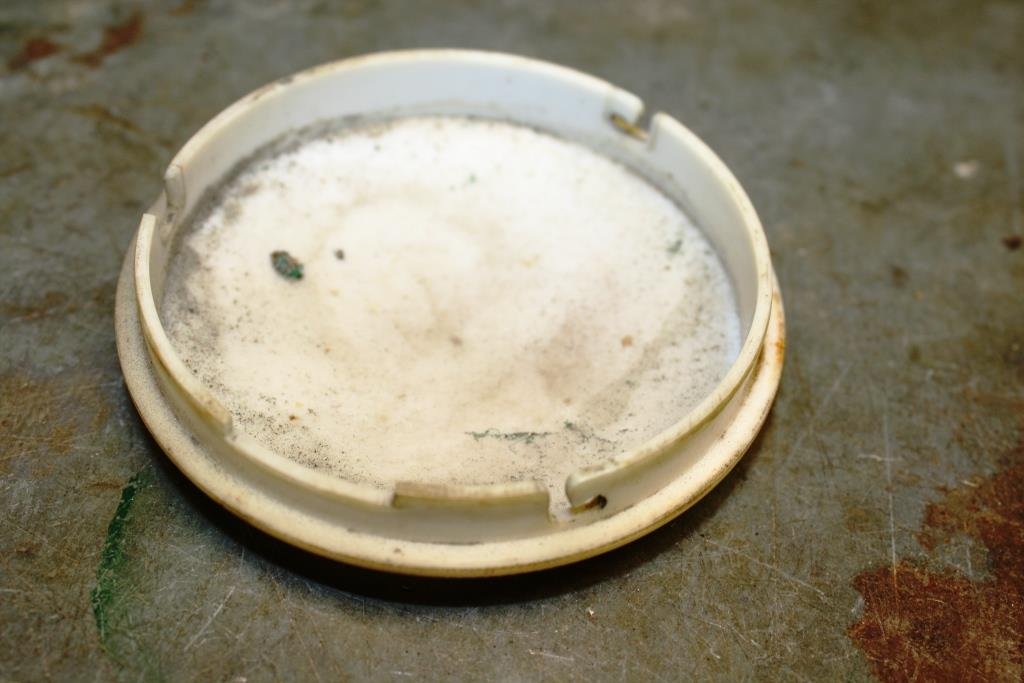
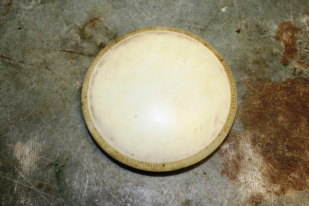
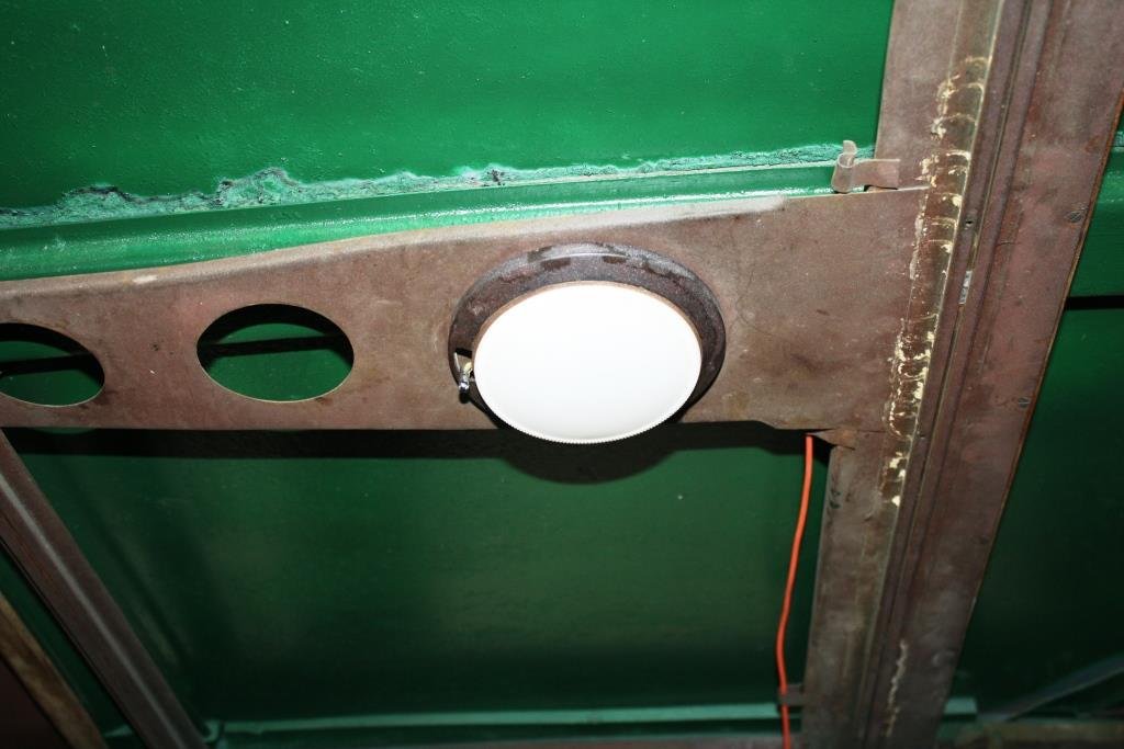
…………Yes I know I’ve been a slack prick, re: this thread. With final arrival of summer the good ship Aquaholic insisted that I take her and some of my disreputable mates out fishing… (What could possibly go wrong?). It was a hot day, we got thirsty, we drank heavily and we “got fush”…….(as you do). A few days later my brother turned up at the Viaduct in this bloody monstrosity, and the good ship Aquaholic (and a certain part of my anatomy) felt very, very, …. small…….(Sibling rivalry can get complicated!). ….so we headed north. The view from the bridge was cool…… Accommodation wasn’t too shabby…. …. And the lounge was bigger than the one at home… Thankfully there was a bar on board for self medication! Back home I was stricken with a bout of the much feared “home handyman-itis” and I accidentally started rebuilding the front of the house… (Note the cunning accumulation of Brownie points with the “ever lovely Mrs. sr2”). After the above brief hiatus I’m finally back to Rigamortice’s wiring. I’m trying to document as much as I can because my memory is like a sieve. I managed to source some cool old fashioned bullet connectors…. I’m almost finished under the dashboard, getting sick of working upside down. The dip switch still works so I hit it with some contact cleaner and we’ll see how it lasts. I’m running relays on the lights so it won’t be carrying the amps that it used to. I’m using my 70 year old meter just because I can. The horns are all wired up but they sound like two strangled cats, I’ll have to do some research on how to tune them. Circuit breaker in place instead of a fusible link. Mounted the battery earth cut out through the fire wall Repurposed an old offset ring spanner for a battery clamp. Managed to get some life out of the interior light with a new bulb and fresh wiring. Cleaned a ton of crud of the diffuser…. And it works.
1 point
-
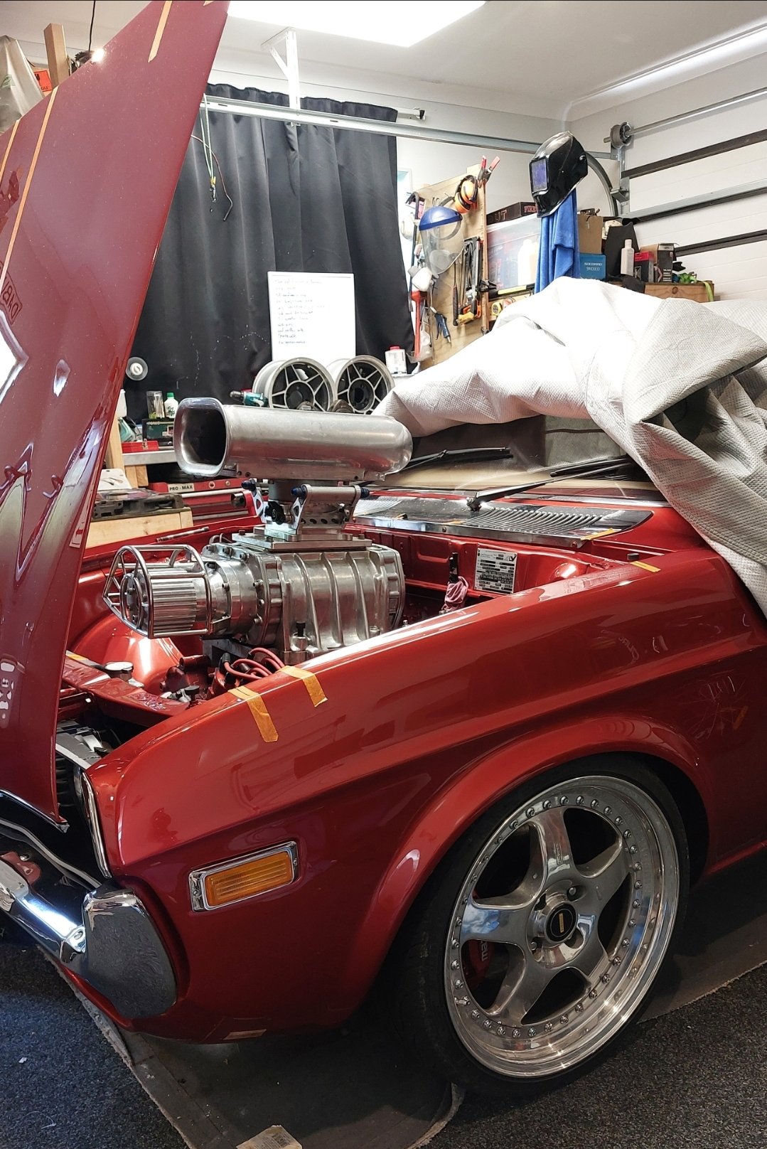
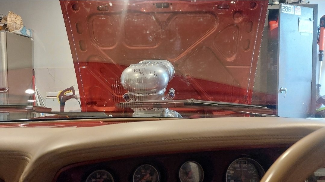
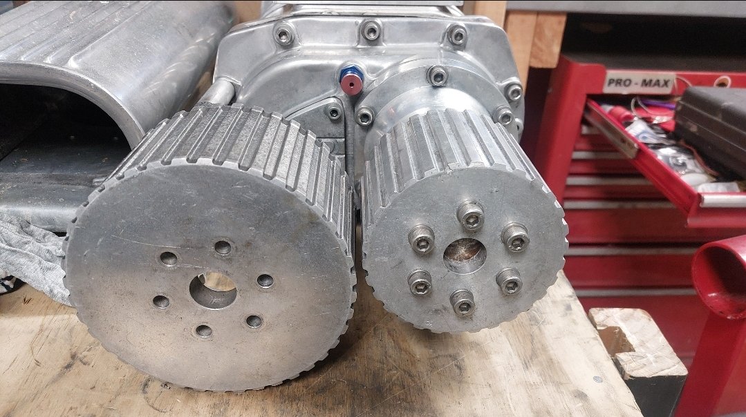
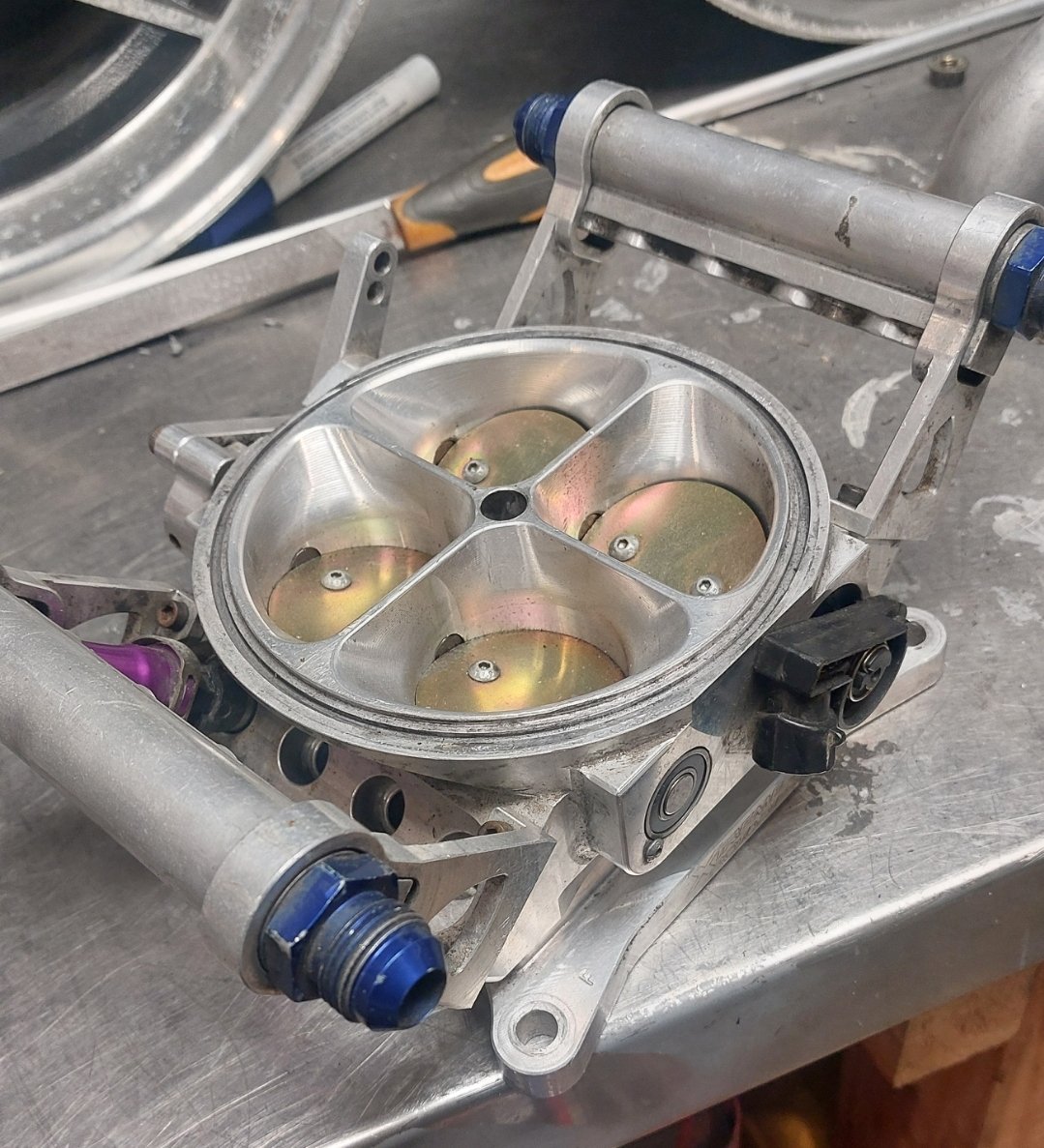
Sold the ROTECH BP, but before I whip it out, have dummy mounted the blower to check cut lines for the bonnet, so I can put a massive hole in it. 40 vs 30 tooth (1to 1) pulley, Unfortunately I'll have to run the under driven pulley to get it through cert which is only 7-8 psi. The small pulley will be double that, but intake temps will skyrocket, and I won't have enough money to get car legal as well as work on cooling. Water meth will be on the cards, as is maybe Water to air intercooler. I'll just focus on redesigning the intake, building a fresh new block, setting up EFI and a host of other items before I worry about decent power. Also that scoop won't pass, so I need to find a low profile solution for air filtration into the Xtreme rotaries 1200cfm 8 injector throttle body., I'll only need to run 4x 1000cc injectors for what I'm doing
1 point
-
I glooped the two halves together, bolted them up, bolted the tailhousing on and let it set. Following morning it was bolted onto the engine, unsurprisingly a bit heftier with all the gubbins placed back within the box. Its about 9kg heavier than the standard imp box. I then started to fit the first part of the gearshift linkage. The first of those snazzy universal joints, handily available in a diameter to suit the shifter shaft on the Subaru box. I just needed to add a small locating hole for the grub screw... Universal in place.. Engine and box were then bolted back into the car. This bit is so quick and easy when using the 'engine stand 2000'. It takes about 10 mins and I'm getting quicker. It'll be slower when there's shift linkage to undo and driveshafts to slip out of the way. But at least the main heavy awkward part is actually easy. That lot in place I took some pics. Its neat to be able to look out from the one of the lounge room windows down onto the workshop floor and see this... With that lot in place I was able to suss out the angles I could get away with, as shallow as possible and allowing for the handbrake mechanism. I had this old imp gearstick assembly that @dmulally kindly posted over to me. Some previous owner of the car he got it from liked painting things. Everything. Multiple times... I scraped all the layers off, took it apart and cleaned off the dirty old grease. Discovered it had been cobbled together from two old shifter bases. It was originally a very early Imp unit when the very first cars had an automatic choke, which often proved problematic. Hillman then changed the cars over to a manual choke with a nifty little lever in front of the shifter. This mount had been added to the early base. Which means they must have chopped up a later baseplate to get the choke mount. Why they didn't just fit the entire newer base plate I don't know. But what I had in front of me was a frankenstein of base plates with barry spec welding and fixes, but also including a not too badly made bronze bush on the lever where there is normally a (wornout) plastic bush. I had a couple of shift rods to choose from. I chose the least worn. Moving back to the gearbox end I machined up some shaft ends from stainless bar to suit the universal joints. I had some stainless tube and welded the ends in place on the first shaft that runs from the gearbox universal down to the tunnel. Now I needed a sturdy, slippery support to mount in place of the second universal joint. This will not only take back and forth movement on the shaft but also a bit of thrust loading created by the angle on the connecting shaft. I had already bought a lump of slippery hard engineering plastic with this application in mind when I had ordered the plastic for the flywheel thrust bearing a while back. It was bright yellow. Luckily not seen under the car as it would clash with the blue paint. I put a hole in it and machined the outside down. Which also created a pile of pretty swarf.. Then reamed it out to 1" Still a bit tight so out with the adjustable reamers.. until it was just right... Then made a stainless cradle .. The cradle got some wings welded in place and I dug the rivnut tool out.. Mount now bolted in place in the tunnel I had to chop the last tube to the right length, weld on the end and bolt the universal in place.. The front end below the shifter was was standard imp stuff and this is where problems popped up to throw a medium sized spanner in my workings. The side to side gearstick movement across the gate was minimal. Ridiculously so. Like about 1". Or 25mm in new money. Yet the fore and aft movement was about right. But quite stiff. I was contemplating why this was so and what I could do to remedy this when I also noted that 1st gear was where 3rd was and 3rd was where 1st was. Poos. Four years ago when I had compared the Subaru gearshift pattern at the box to the imp unit I thought they were exactly the same. But I had not accounted for the reverse rotation taking place under the imp gearstick. Also I never really thought much about how little of rotation the Subaru box needed on its shifter shaft to shift the internal selector across the 3 rods. Its a tiny amount, like 3 degrees say. Whereas the Imp box has a shorter internal selector and requires more rotation at the shaft. Hence the Imps gearstick knob only moves a teeny bit when coupled to the Subaru box. But the Subaru box has a standard/similar amount of rod movement within (ie 1-2 and 3-4th) which was going to make things trickier to fix. Simple linkage/leverage multiplications that is easier to see than explain. Sorry if your brain hurts. I had to hurt my brain a little bit to suss out a solution but there was only a little bit of smoke. The reason the scooby box is different becomes obvious when you see the scooby shifter setup. Which luckily I can show you because last week thanks to @Leone I was put onto a local fella to me who happens to have many old Leones and Brats kicking about his property and he had a spare leone front wheel drive box that I wanted (always handy just in case...) His property is amazing!!! Long 4wd only driveway up to a ridgetop house with stunning views out over Tasman Bay. Old leones just kicking about... Luckily we have our trusty old 4wd Hiace and that became the days gearbox transporter... Box on bench. Look at that shifter mechanism... The shifter rod attached to the gearstick only rotates a tiny amount when the stick is moved sideways across the gate. But the rod moves 10mm in each direction when shifting for and aft. Simple. Robust. Very Subaru. I can't copy it though because I have turned my box 180 degrees. No matter where I put my pivot point (below or above) I'll have one of the planes working backwards. So I decided to build a new shifter base setup. The most important thing was to reverse the rotation so the gearstick pattern is correct. The imp pivot point needed raising to allow the offset shaft end to be rotated to above rather than below the centre line, so reversing the across gate movement. I would add the ability to adjust both rotation and lineal movement. Started with a new pivot cup because I was not happy with the worn and Barried pressed steel item.. I dug out a large lump of steel bar... Chopped out a square and cleaned it up in the mill.. Big drill = big hole.. Rough machined out a cup shape. Cut a form in cardboard to suit the brass ball and used a die grinder bit to finish the shape... Grinding paste time... Slots for pivot pin.. Lightened the lump down.. Built the shaft up with weld and machined it down so I could add a lower pivot point. Milled some steel like so.. Welded a boss on.. New socket for shift lever ball end... Cut out Barrys previous workmanship... Machined up some spacers and a base plate.. Welded up a little tower (my stainless and steel tig welding is definitely improving, helped muchly by realising that not being able to see what I'm doing does not help much and finally admitting to my age and buying some reading glasses....) Welded tower to base.. Now all together please... Bolted together. You can spot the adjustable rotation, which the spacers allow for, along with adjustable pivot point. In place... Yay- it works! The shift pattern is correct and the action is much smoother. The spring loaded indents on the internal gearbox shift rods are quite stiff, which I noted was the same on the other box with its stock shifter. Its a bit baulky to push past the synchro baulk rings into gear but I think will feel better when the gears are actually rotating. There's certainly no slop in the system and it feels very mechanical - not rubbery. I now note how much flex there is around the shifter base in the imps tunnel (granted a very rusty shell..) Its something I might just try to stiffen up on my blue Imp when fitting this lot in. Phew. That was a little mini engineering mission I was not expecting but that's this project in general1 point
-
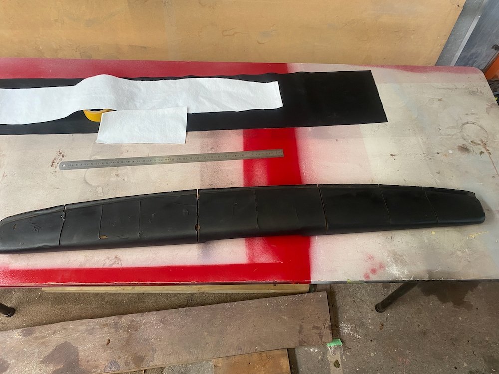
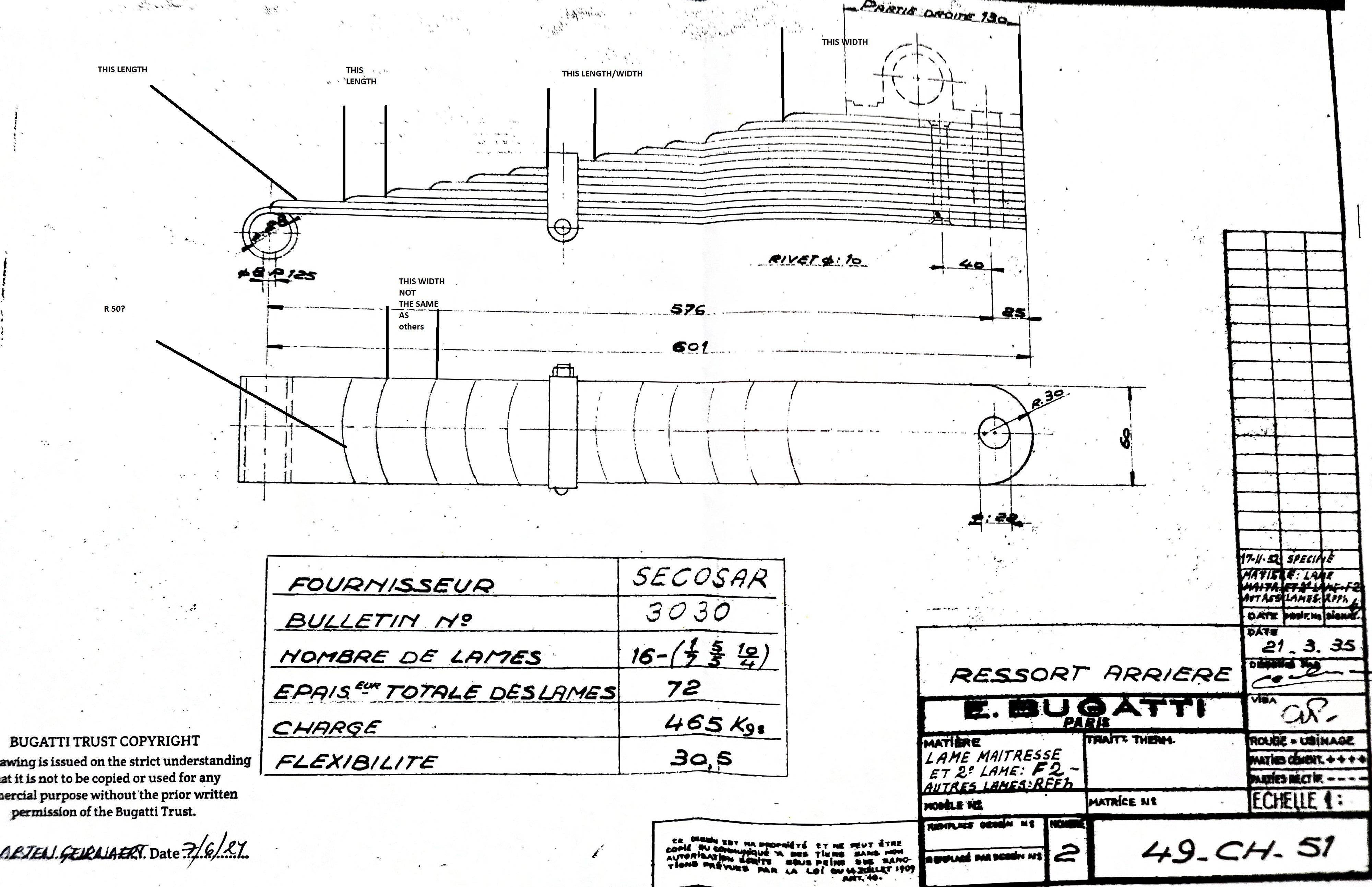
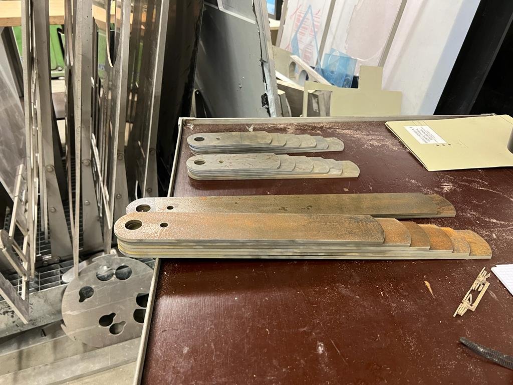
Rear Springs: My original rear springs are typically Bugatti in format: a forward-cantilevered quarter elliptic multi-leaf array. The springs in my 2 sets were pulled apart, and they showed heavy rust pitting to the extent that they were not going to provide reliable suspension without cracking or breaking. So, we decided to get new springs made. There's a place in countryside Victoria that specialises in re-fabricating new springs for old cars, and when they examined one of my spring-sets as a sample, they went "Yeah, yeah, yeah, nah." It was going to be too much work! A bit of internet research alerted me to a specialist in the wilds of Wales, but he only does work when requested by Tim Dutton, and he was on the verge of retiring. Then I found a chap in Belgium who had just finished making new front springs for a Type 55 - he posted a short video of himself jumping on them and bouncing around - a I figured that we had found the right guy for the job. There was a bit of to-ing and fro-ing involved: the original array for the T49 springs is 1 leaf @ 7mm, 5 @ 5mm, and 10@ 4mm. No-one, anywhere, has access to suitable 7mm thickness spring steel. We got spring engineers and gurus involved, and ended up with a revised recipe for the leaves in our spring array: 2 leaves @ 6mm, 4 @ 5mm, 10 @ 4mm. Same overall depth to the spring array. A Bugatti factory drawing showing the original rear spring array dimensions. This gave us a good specification to work from. The process of fabrication, further machining, bending and tempering took way longer than expected, as a result of lockdowns and a cardiac crisis from the spring-bending consultant, but finally the 2 spring arrays were completed and assembled. In this pic, further radiused bevels are yet to be cut into the nose of each leaf, and then they get curved and tempered to suit the specified load and deflection.
1 point
-
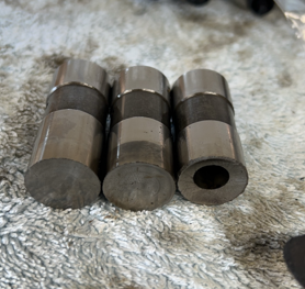
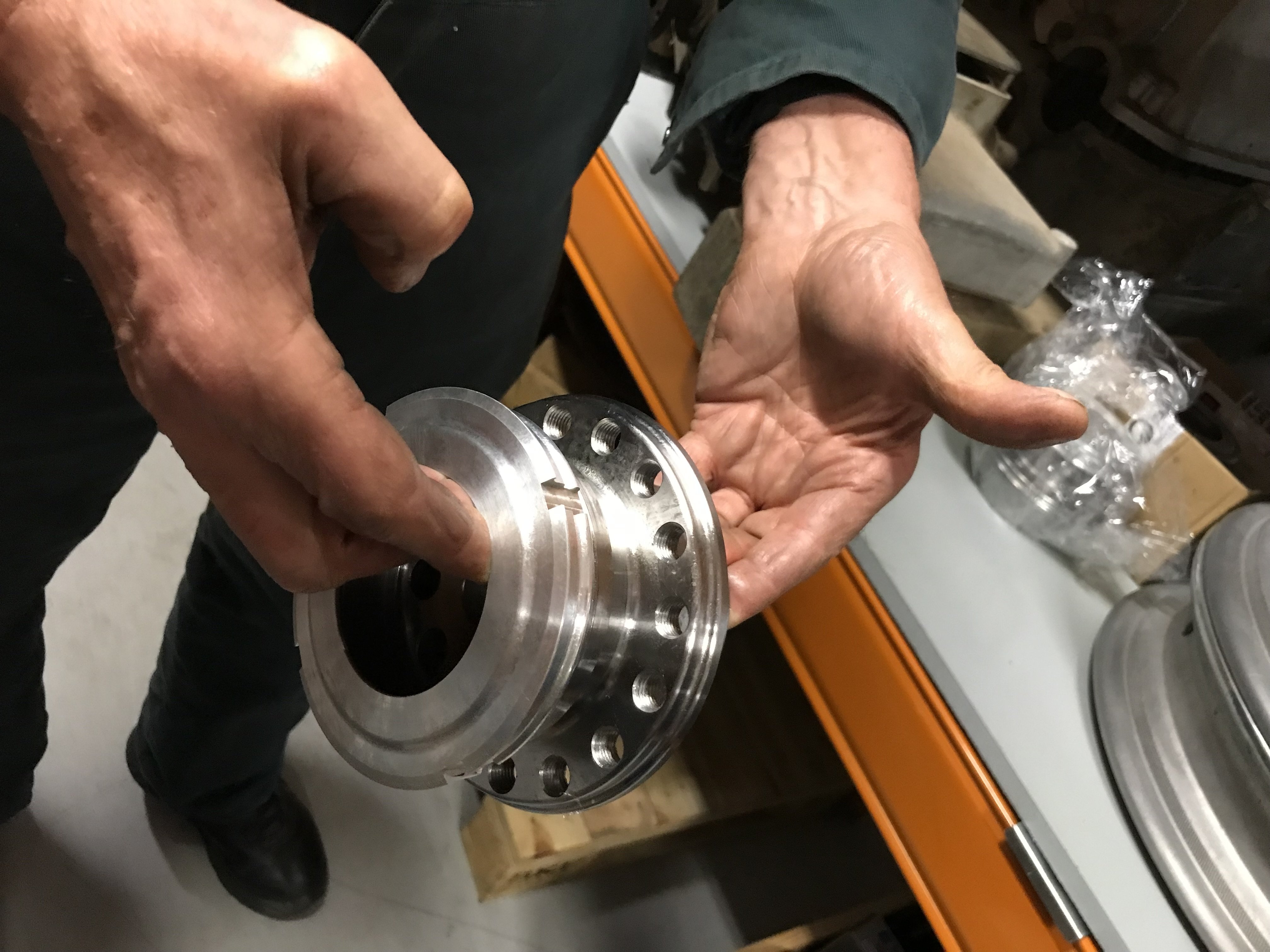
Rear Axle Outer Hubs: To secure the fancy alloy wheels onto the stub-axles on the T49, Bugatti designed a rather complex outer hub. In my pile of bits, I had one of these, but not the other. There's a mob in Geelong South who specialise in doing custom CNC jobs for racing cars and V8 Supercars etc, and so I sent them my existing hub which they measured and copied x 2 - I figured it was best to go with the same on both sides, and keep the original as back-up. Lovely shiny new things!
1 point
-
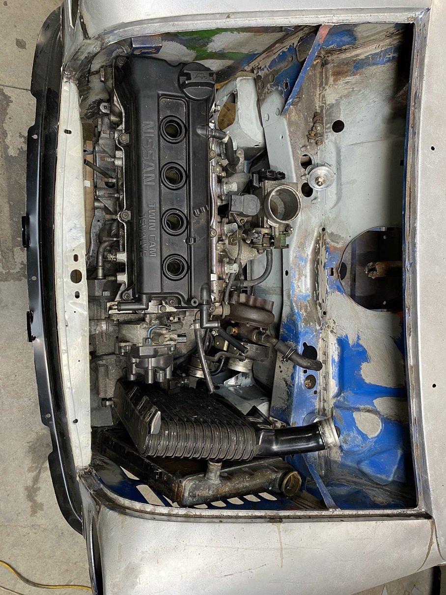
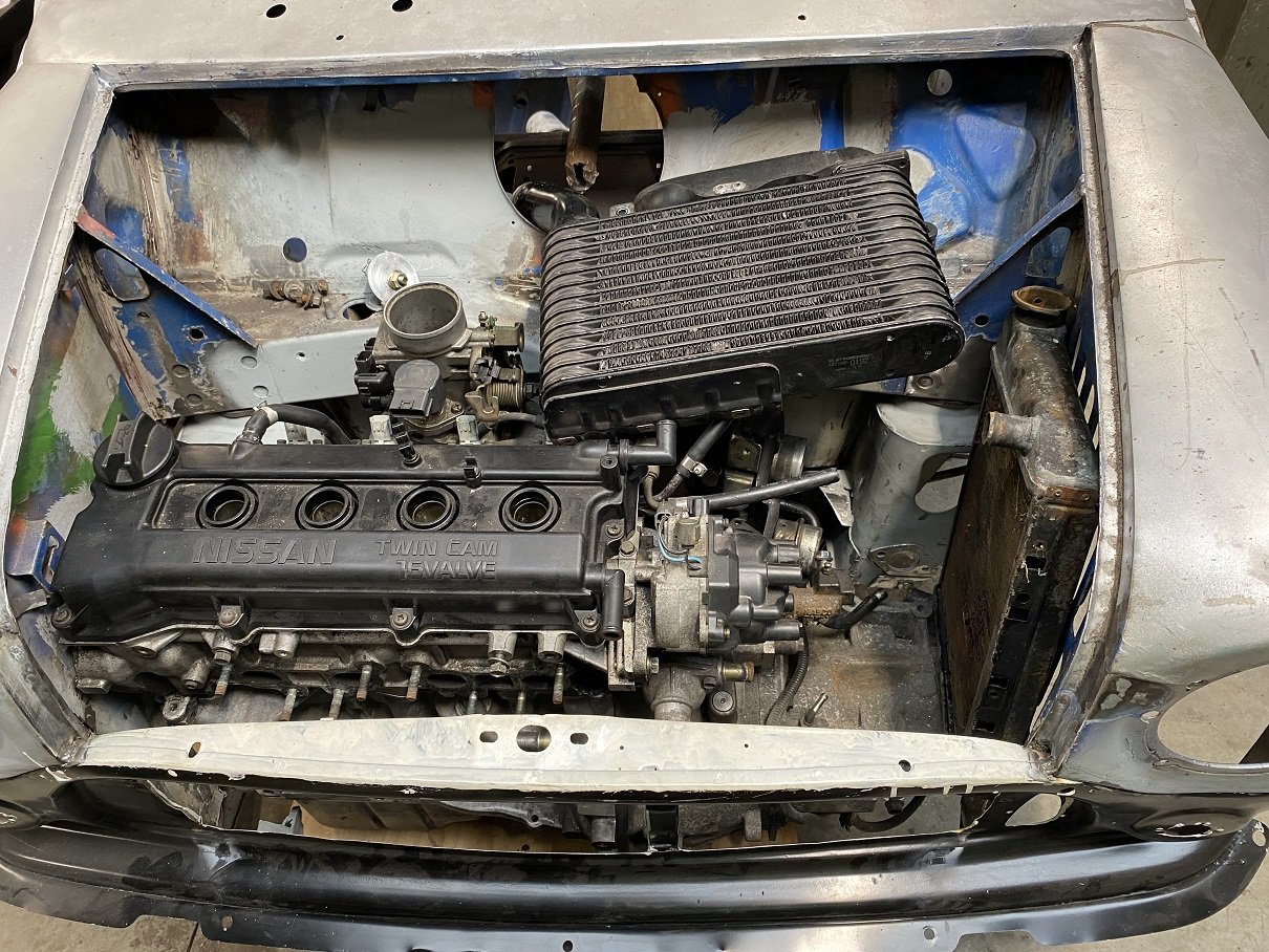
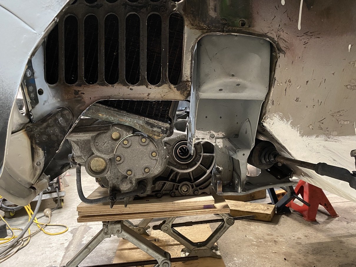
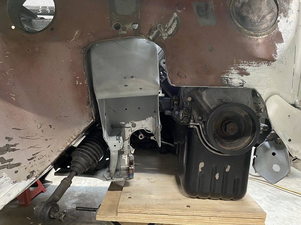
The engine is pretty much in the only place it fits. With more trimming around the back of the subframe I might get another 10mm before the gearbox meets the steering rack. I'm going to step the top/front corner of the inner wing into the guard to get a little more clearance off the corner of the head. I threw some "stunt parts" in the hole to see if there is any chance this is going to work. Mounting the turbo at the front will have almost all of it in front of the grill.... But if I put it over the gearbox... There might be enough room to run the manifold under the engine, then up the back to the turbo then back down for the dump pipe. Loads of room if I top mount the IC.... interwarmer styles. Gonna need a powerful fan and vents... Only done the lower control arm mounts so far. Still got to make a bridge under the top arm mount. I trimmed the inner guards and hammered some new flanges to put some stiffness back in them. Turned out quite good! There will be a CV and driveshaft here to try get an up and down pipe around.
1 point
-
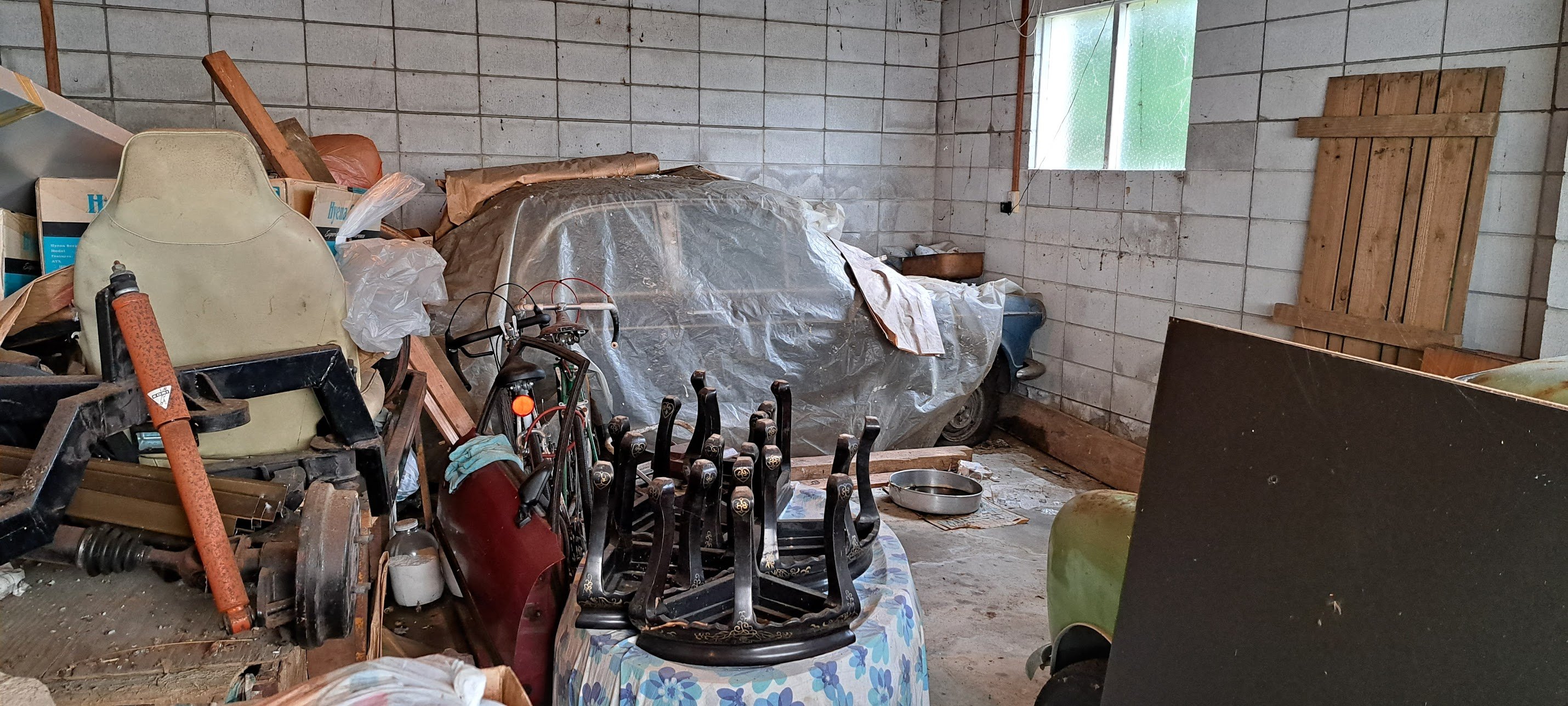
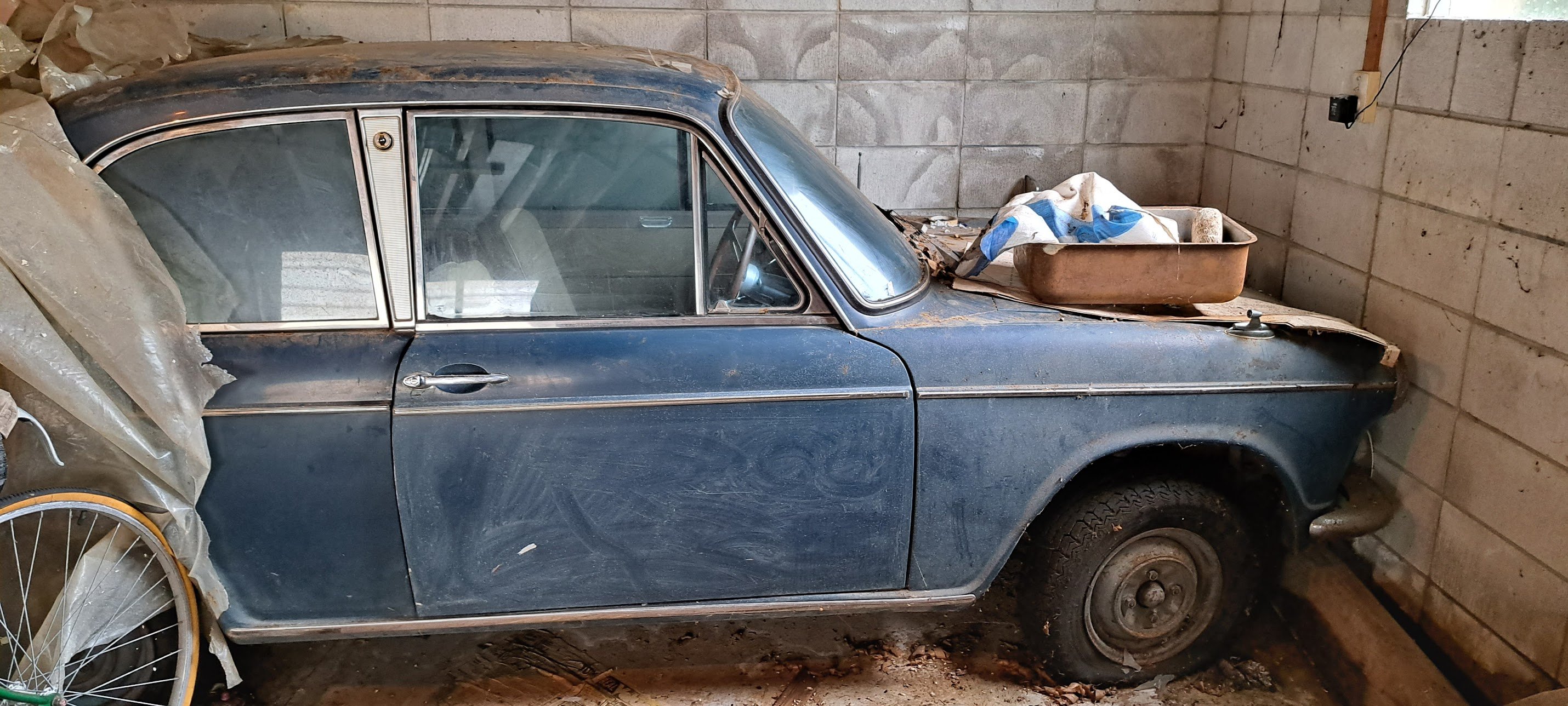
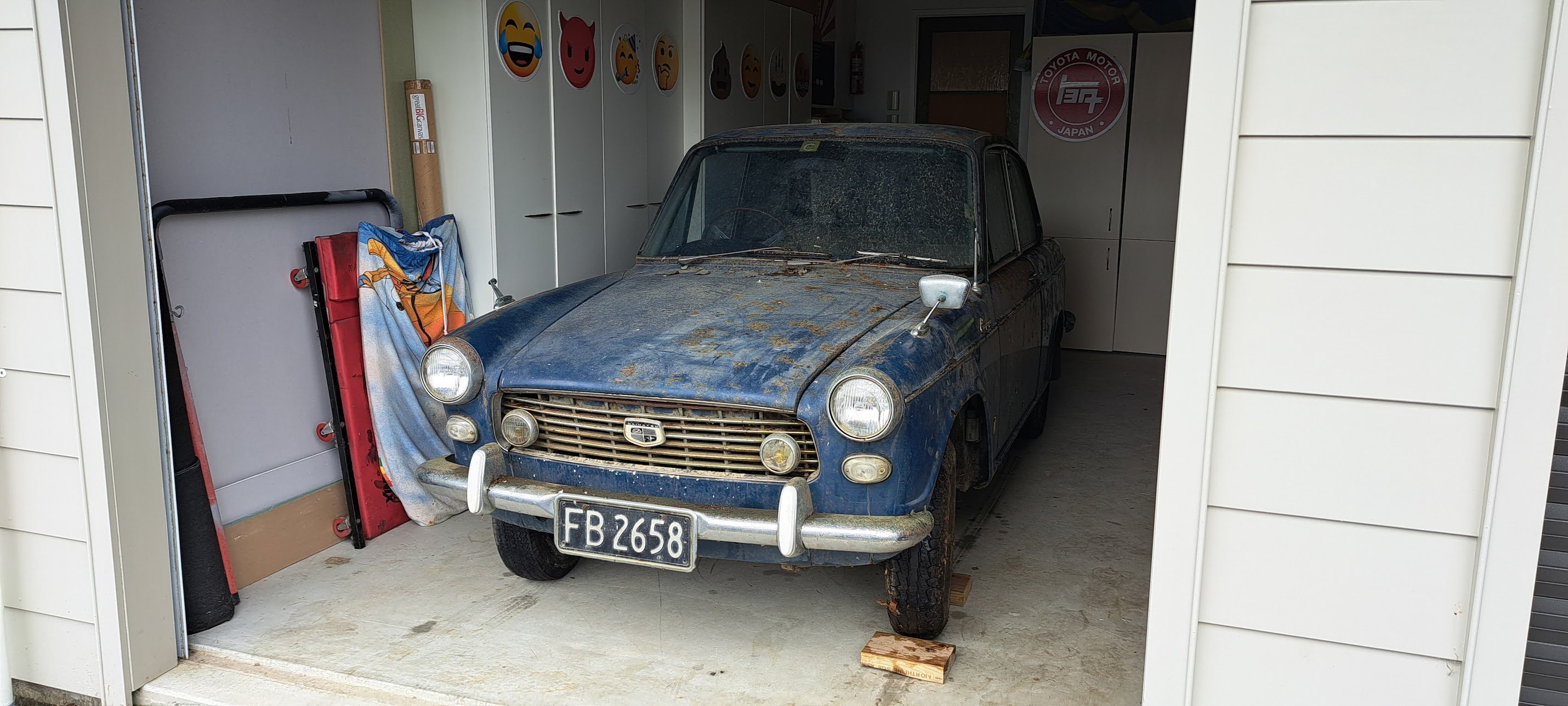
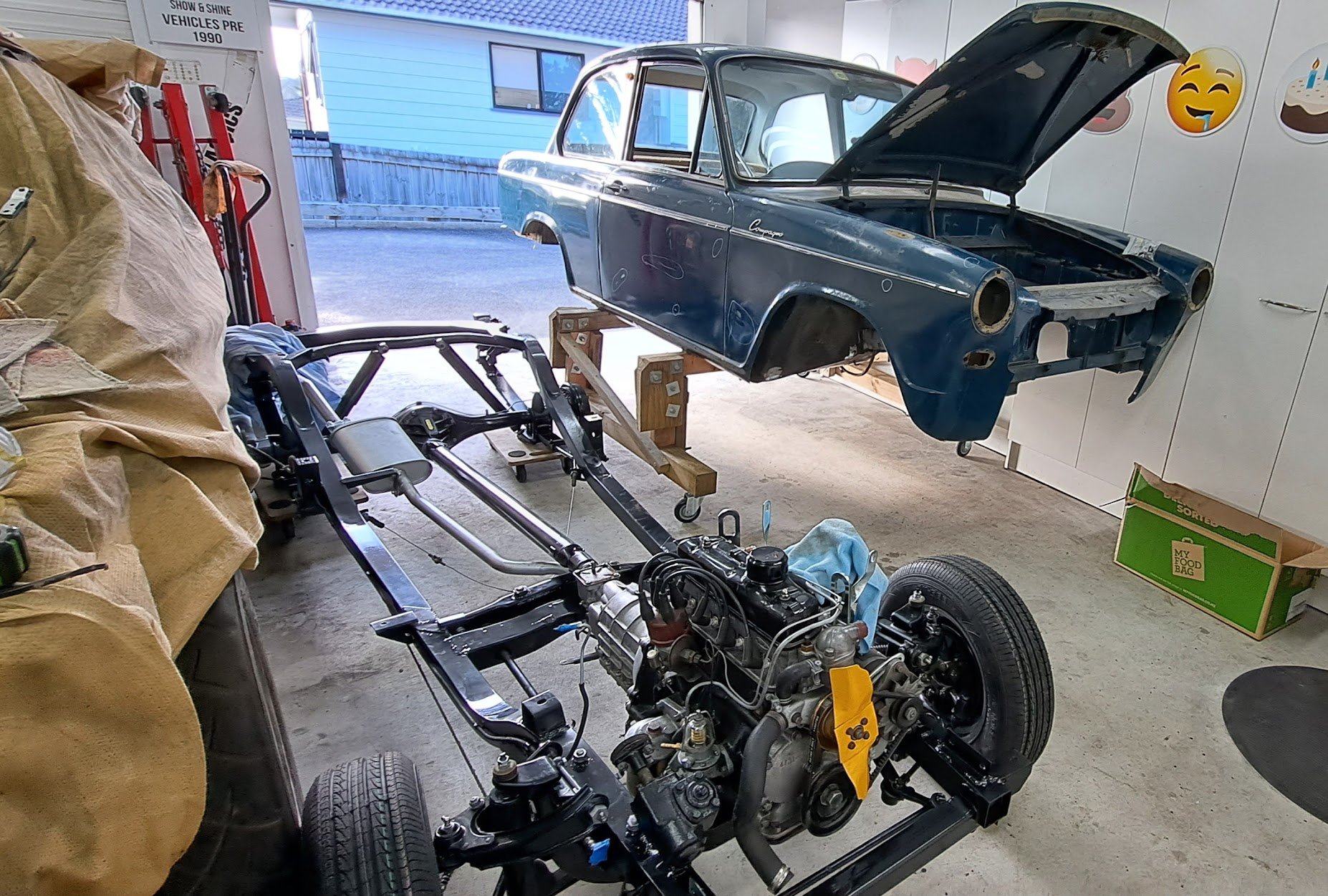
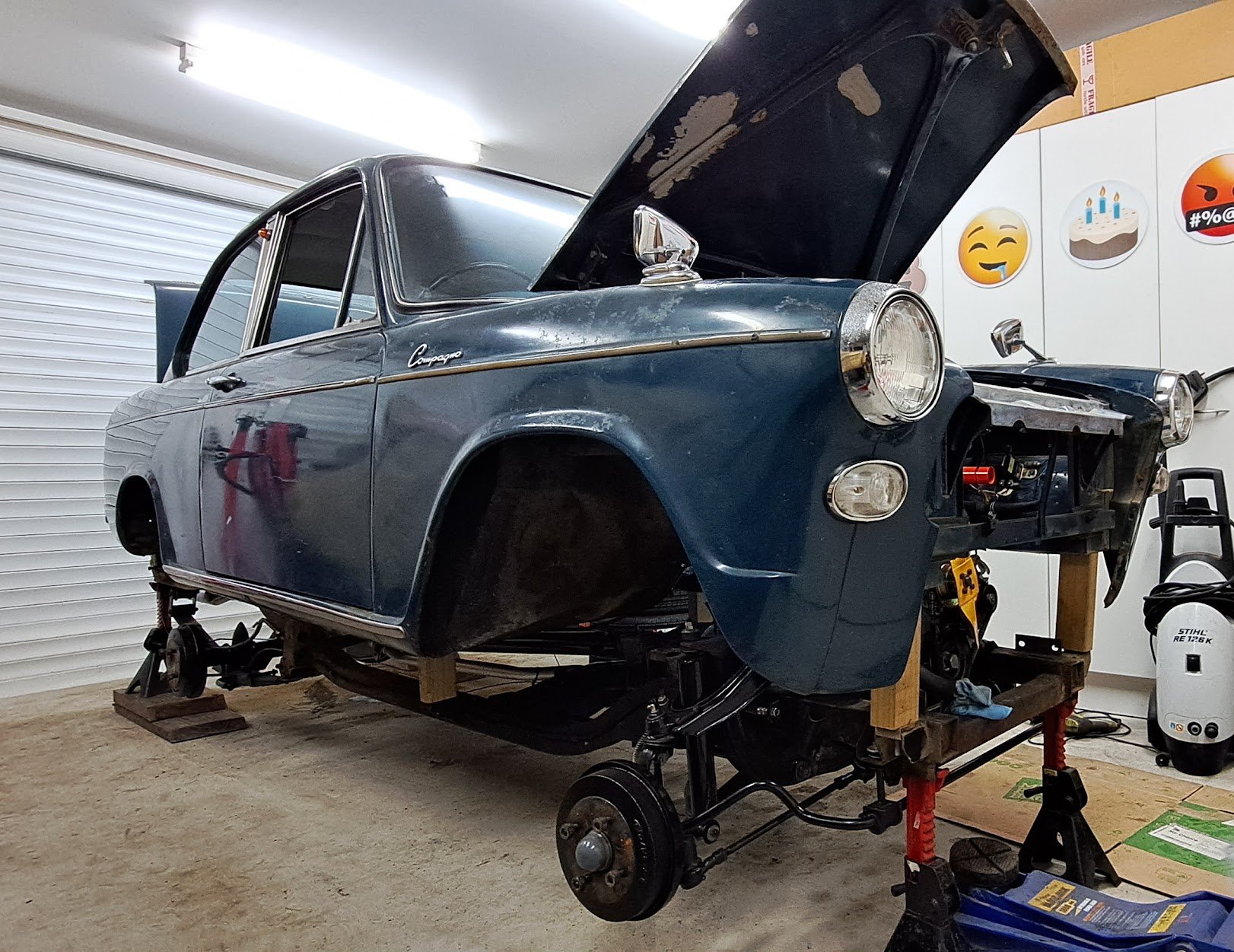
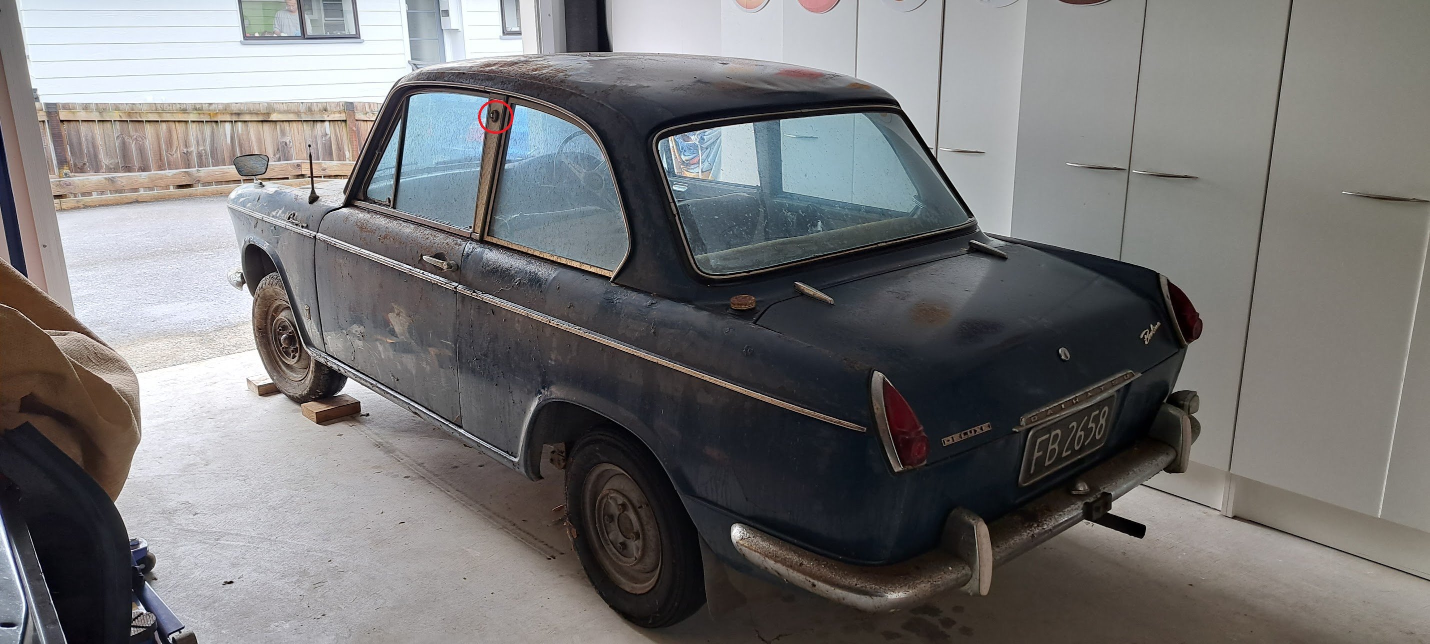
Around 25 years ago i worked with someone who mentioned they had an unusual Daihatsu in their shed. Owned since the early 70's. I'd kept in touch and occasionally asked about it but not much happened. A few months ago i ran into him at a car show and mentioned the car was now available. A "barn find" viewing and unearthing from 45 years sitting in one spot. And I was the proud new owner of this rare little beastie. The details: 1965 Daihatsu Compagno Berlina Deluxe 2 door 2 other owners from being sold new in NZ in 1965 by Campbell motors 53000Miles. Stored since 1977 due to front brake failure and dead alternator. 800cc "FC" motor IF ANYONE KNOWS ANYTHING ABOUT THIS CAR OR THESE COMPAGNO'S OR PARTS PLEASE PM ME For now it will be assessed, and things like brakes and clutch hydraulics will be rebuilt. Motor is locked so freeing this up will be tried. I have the original ownership papers and other details so it should be able to go back on the road relatively easy once mechanically sound.
1 point
-
Chassis fully assembled - with help from my 10 yo nephew who loves hanging out in the shed. Both chassis and body fit with millimetres to spare. onto the bodywork now...
1 point
-
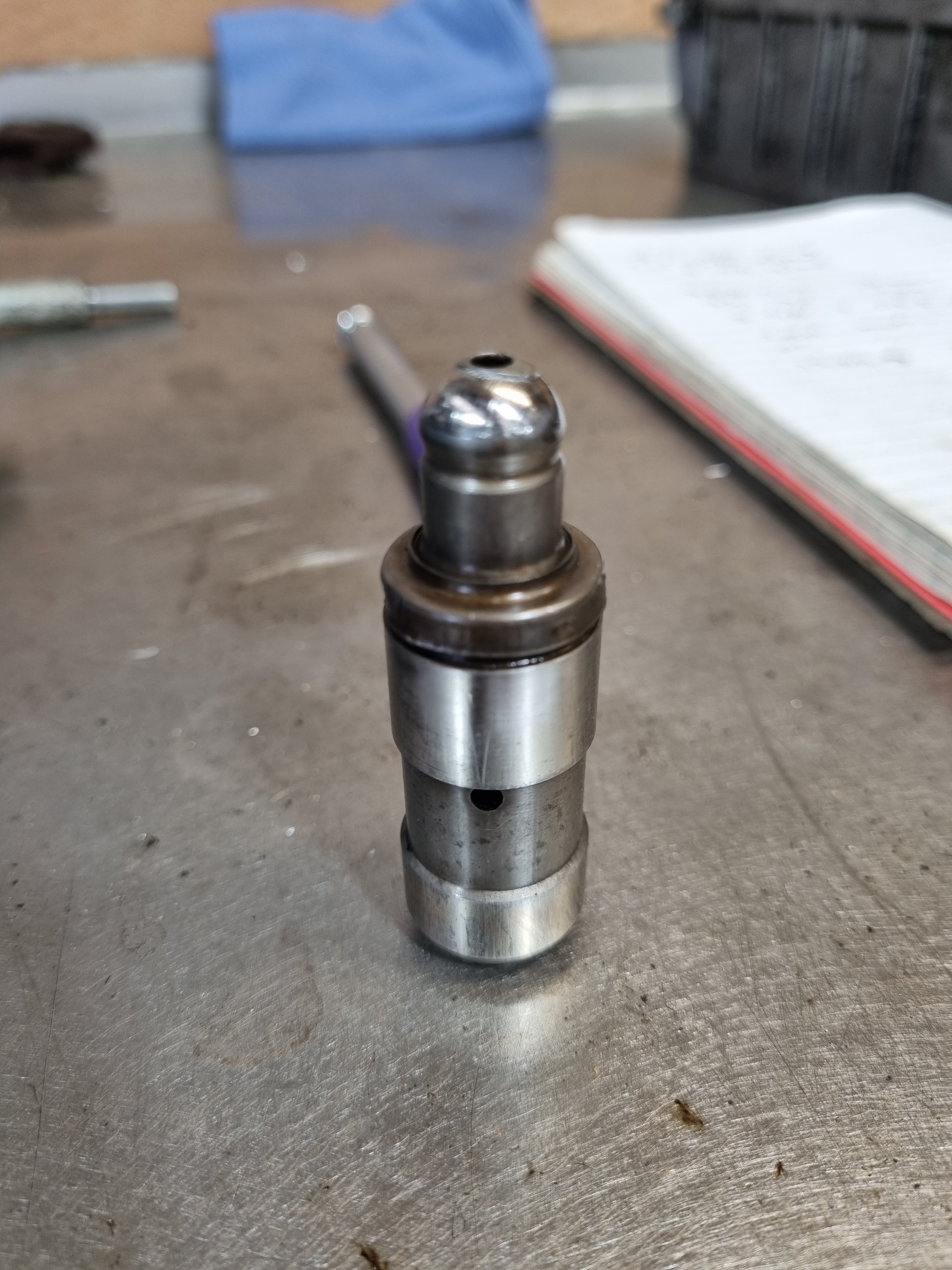
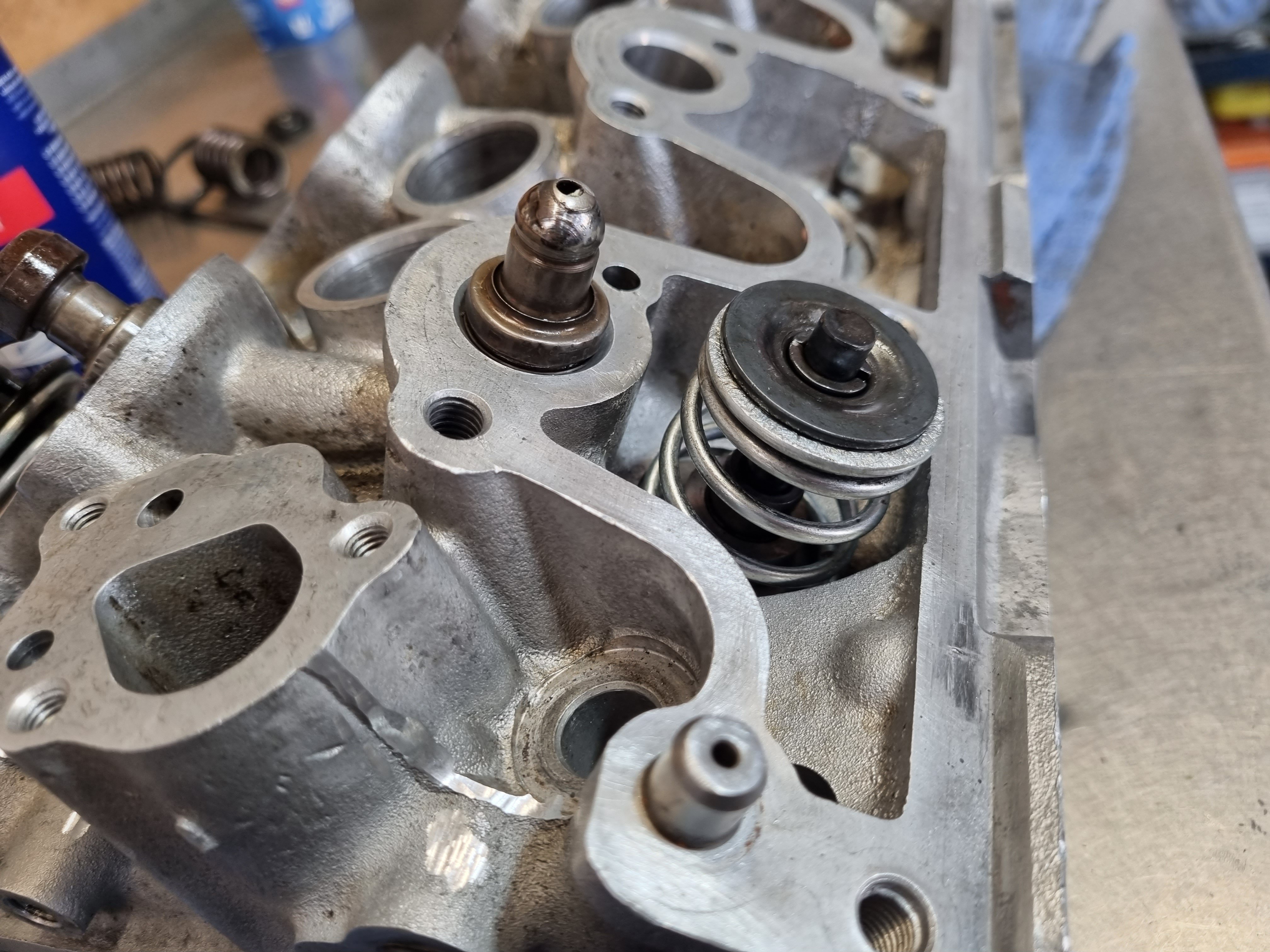
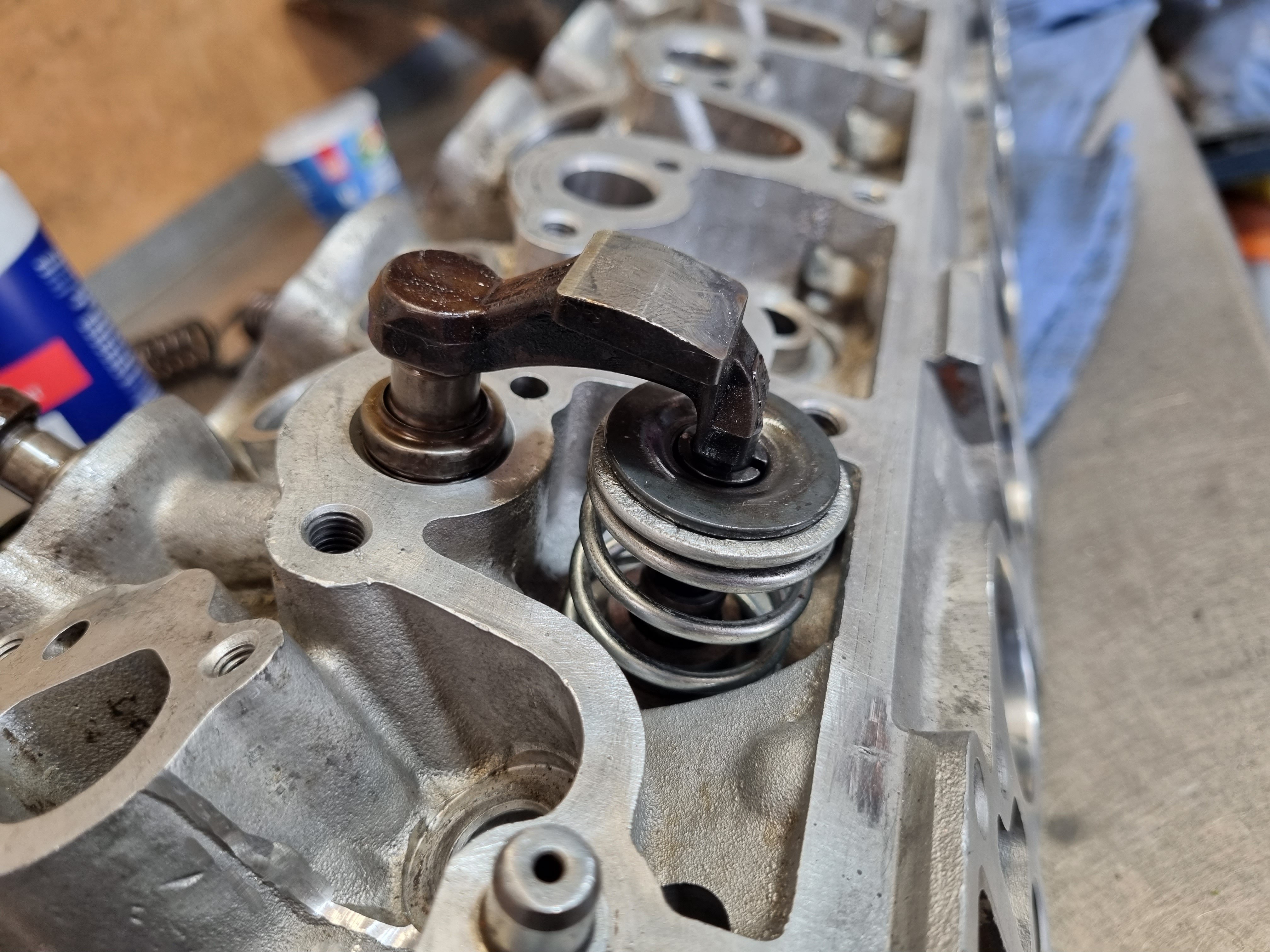
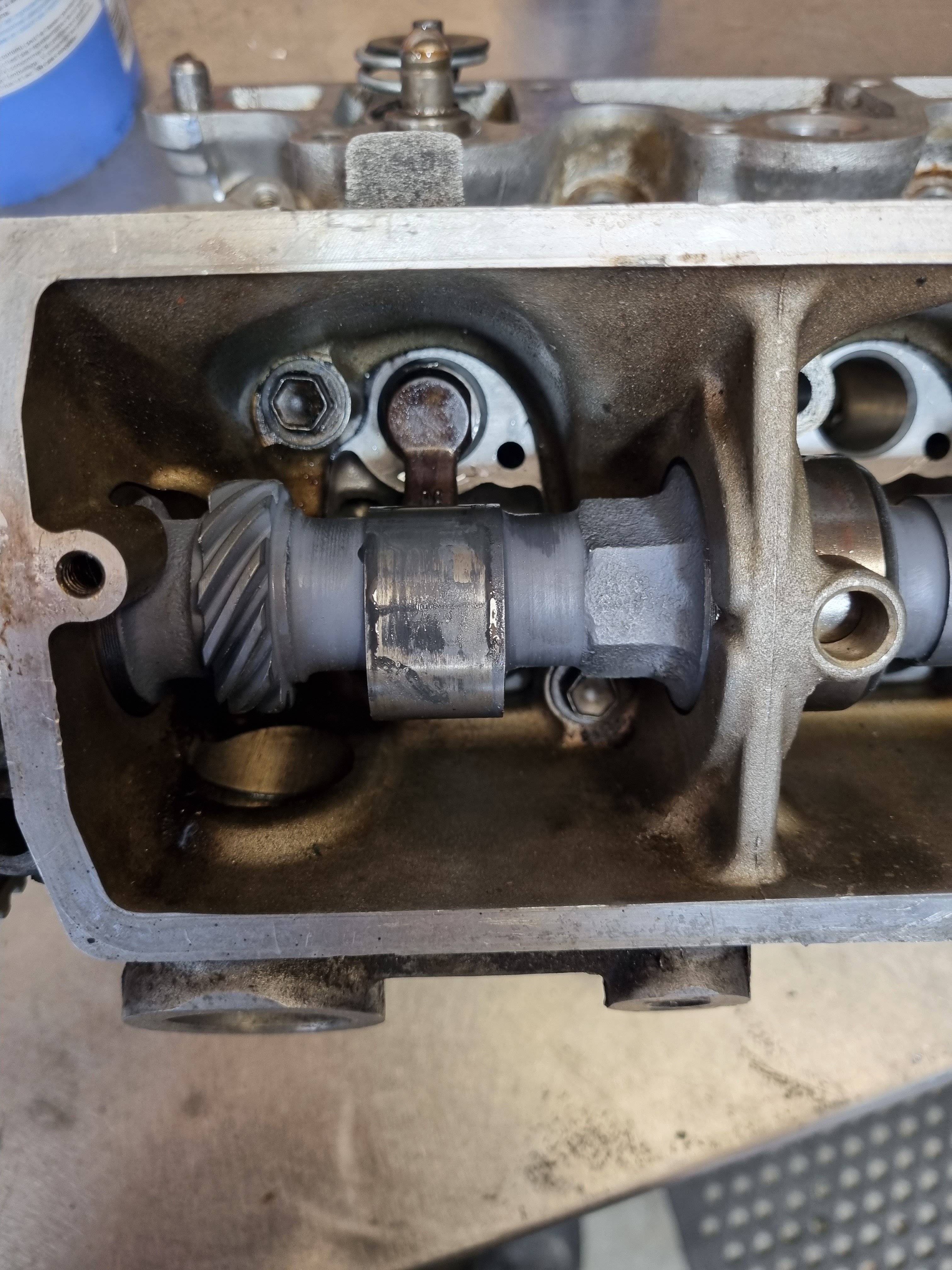
lifter discussion. so Clint rightly pointed out (in the wrong discussion thread) that the increase in pressure or flow to the lifter gallery could result in lifter pump up. i thought about this and did some more dummy assembly and reading. the Toyota lifters dont work the same way as a conventional V8 style lifter. you dont pre-load the lifter in any way and according to the factory manual they should work at full extension at all times and if they compress any more than half a mm they should be replaced. the lifters ive been using to test things have a spacer in them so they cant compress and are extend to max length, that way the clearances and interference i was measuring would be the absolute worst case scenario. the thing thats interesting/a bit concerning is that the lifter is designed (as far as i can tell) to live its whole life at max, or close to max extension. in my mock up assemblies there is no clearance between the cam and the cam follower. so if things get hot an expand a bit in theory it will open the valve on the back of the cam. im a bit confused by this because everything in this collection of mating parts is stock. the base circle of the cam has not been altered, everything is as it should be. i cant see how the non return valve inside the lifter can bleed a bit of pressure to allow the lifter to shorten when things heat up and expand? maybe im over thinking it and it will all just be fine, as i say everything is stock so it must work somehow? ill have to test it as i continue to build the motor. one good thing about having the oil pump driven off a lay shaft is i can spin the pump while the rest of the motor is stationary. that will allow me to experiment with things and see if the lifter will compress with oil pressure behind it.
1 point
-
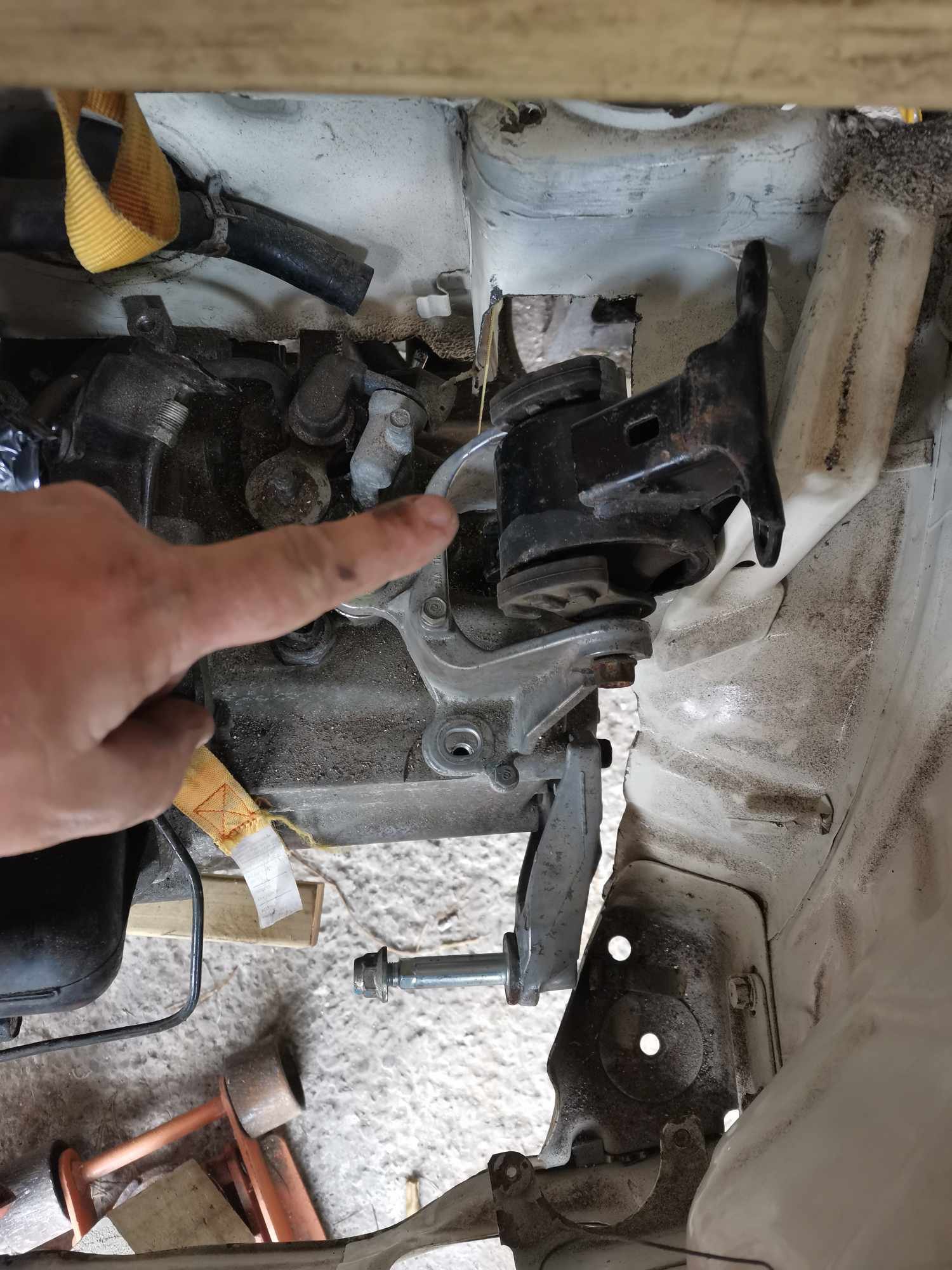
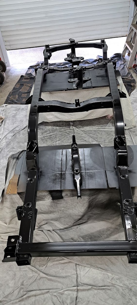
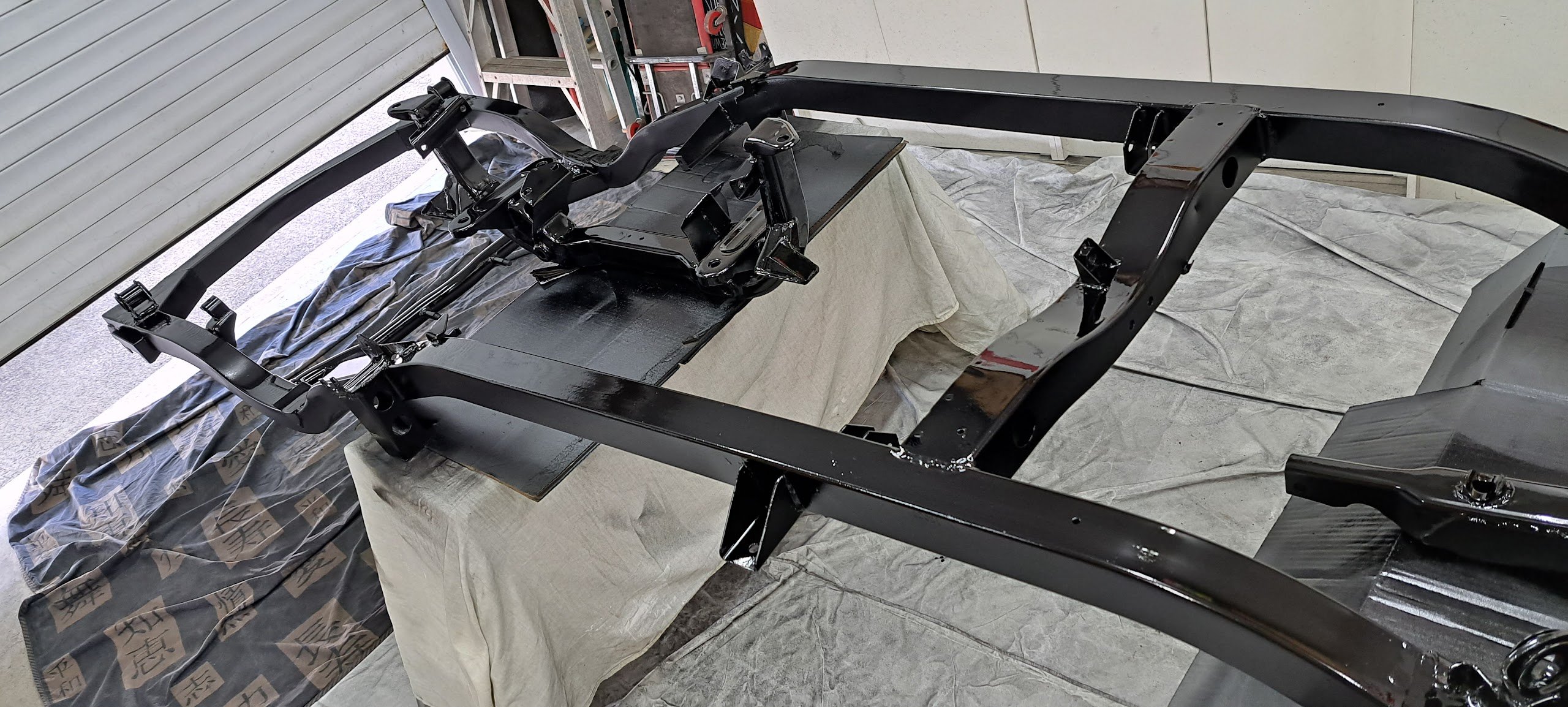
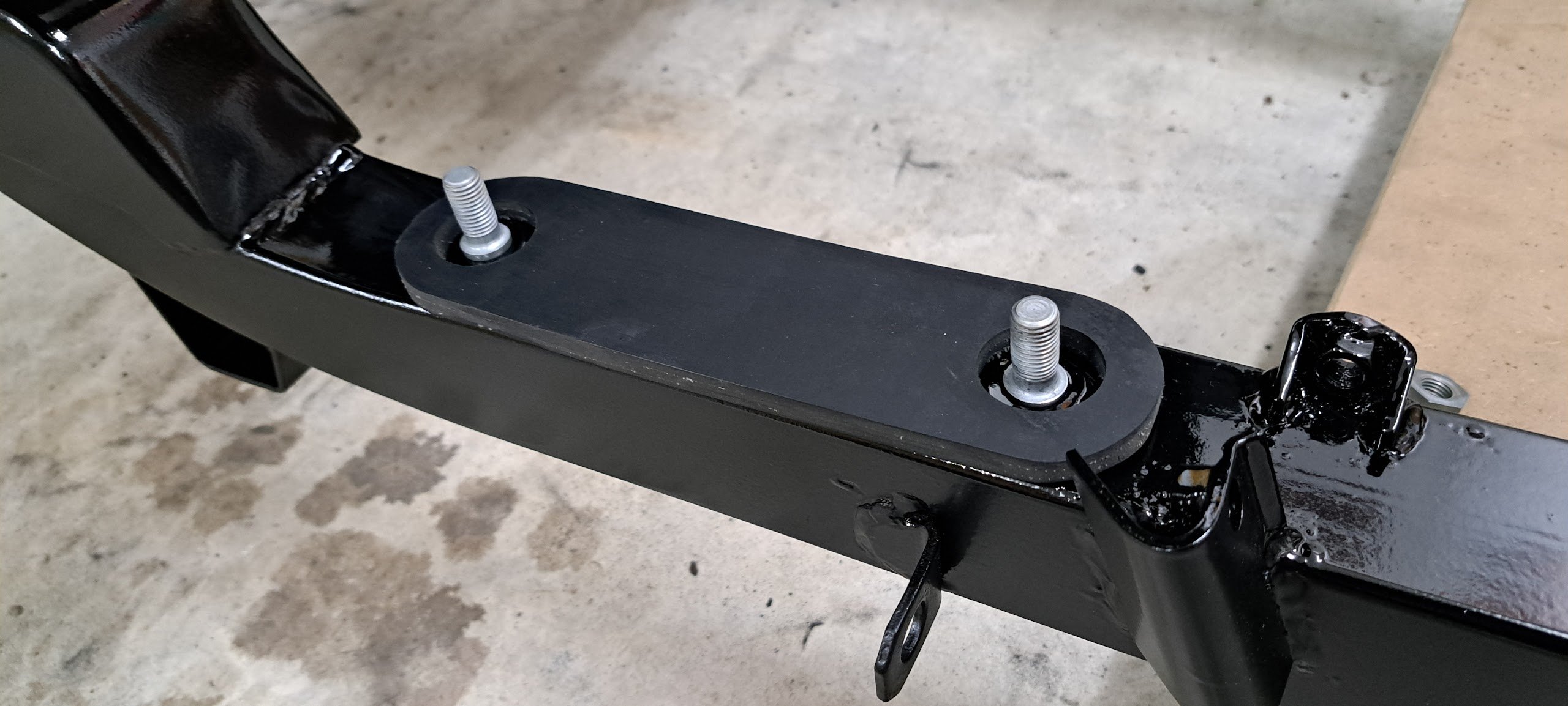
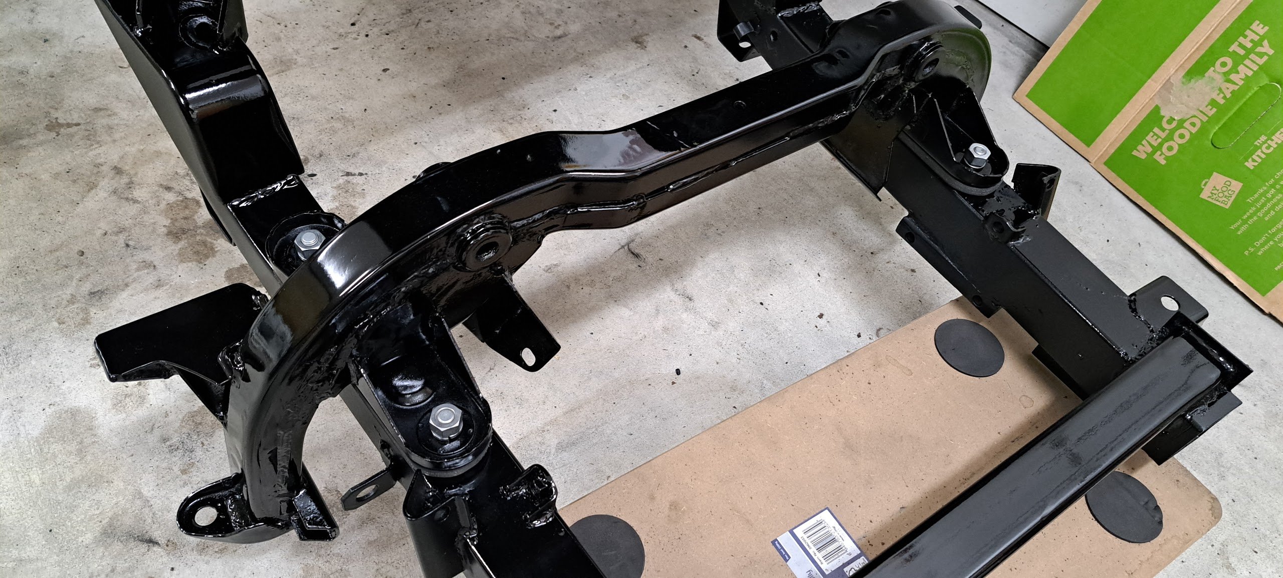
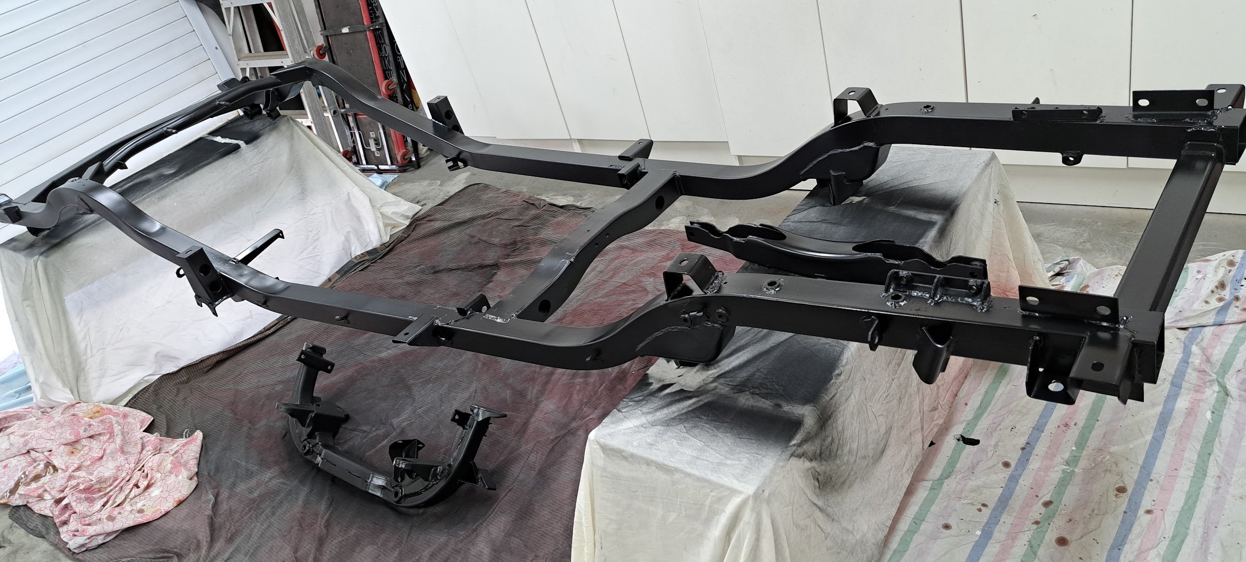
Chassis all painted in 2K black And reassembly started with the front engine cross member with new hand-cut rubber insert and plated bolts.
1 point
-
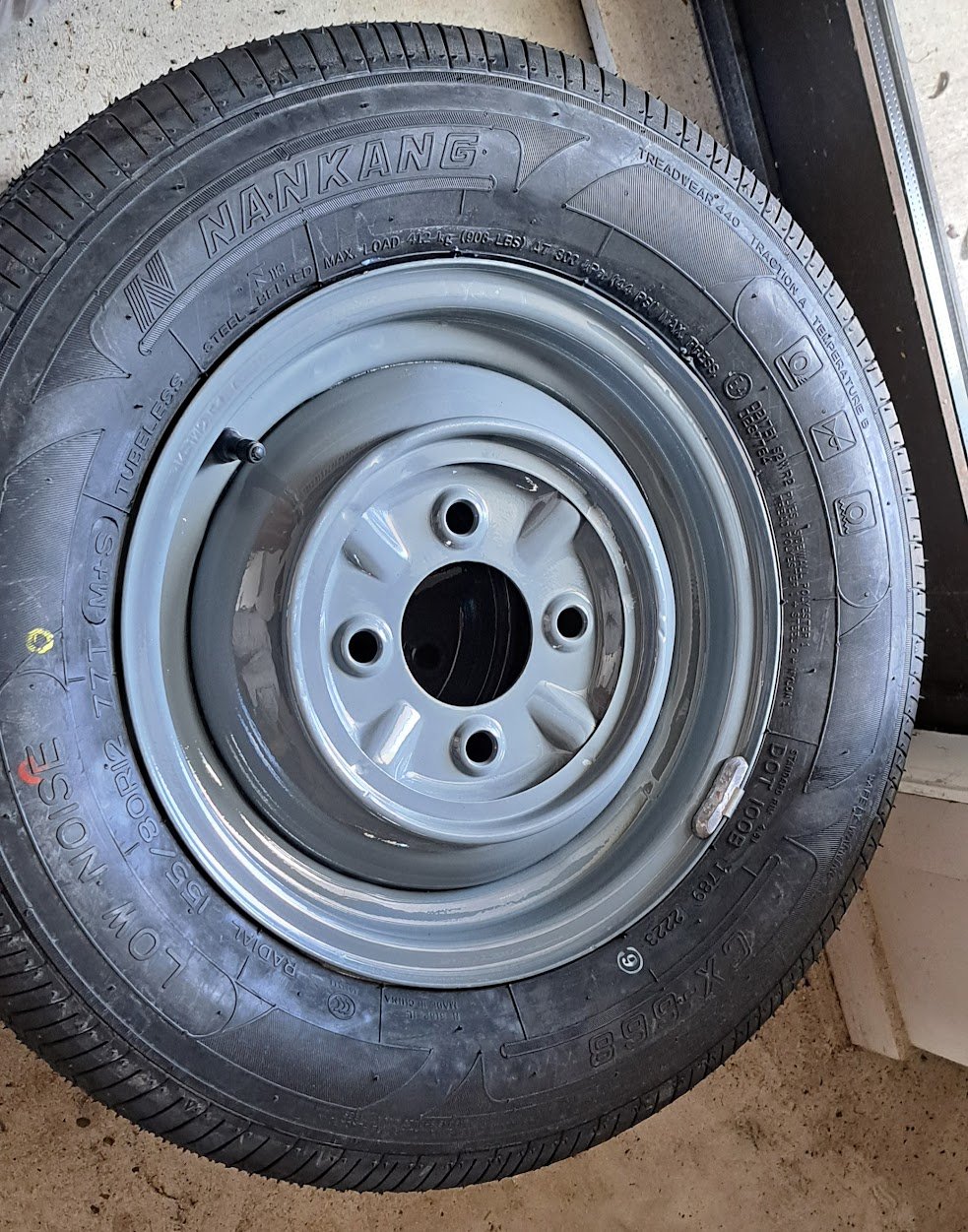
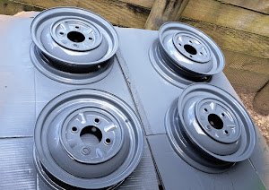
Overdue update - Body spaced off the chassis then the chassis removed completely then stripped everything off the chassis and epotec primed it Also acid dipped the wheels and straightened them up + painted them and some 155/80 R12 tyres fitted
1 point
-
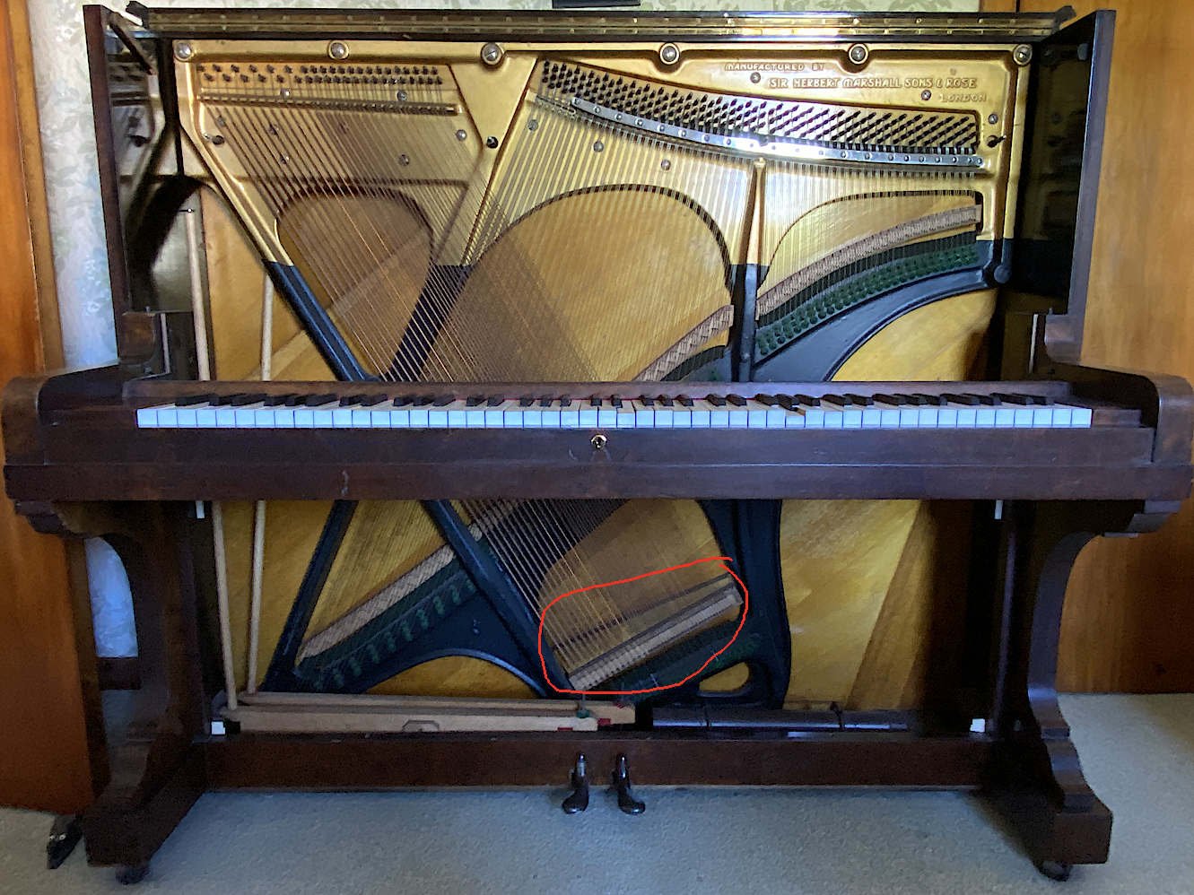
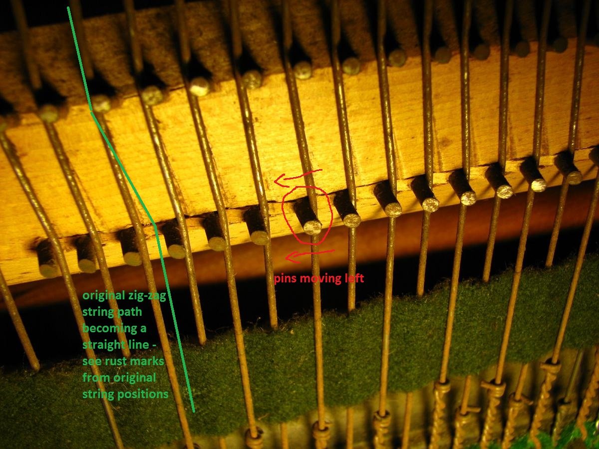
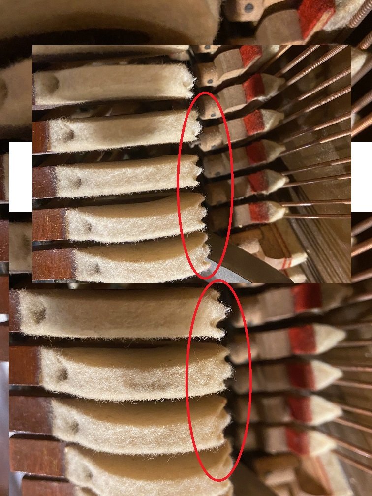
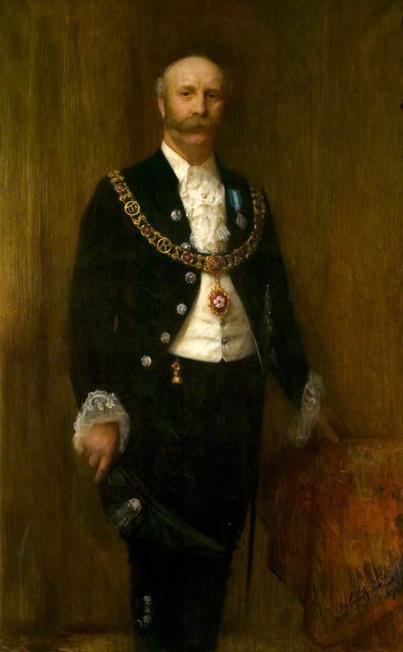
Everything's going according to plan. About as well as you'd expect! I had it tuned just last week and one or two strings slipped immediately. It's a big ask for a piano to survive nearly a hundred years in playable condition. Some selective refurbishment has been done, but the hammers and strings are original (save for the few I broke playing boogie woogie as a kid). Here's some of the stuff that's wrong: The bass bridge (circled in the photo) is shearing/collapsing in the bichord (two strings per note) section, allowing the bridge pins to move under the sideways pressure from the strings, affecting the tone. See later photo. Apparently the bass bridge has rolled, affecting the downbearing. The bridge is a cantilevered design, suspended in space and only attached to the soundboard at a point slightly closer to the soundboard's centre. This allows the bridge cap to be positioned closer to the bottom of the piano to maximise string speaking length, while having the string vibrations conducted into the soundboard at a more central point where the soundboard vibrates more freely. I think. The downside is that the bridge cap's not directly supported, so the cantilever can be crushed back against the soundboard under pressure from the strings, until the string downbearing is insufficient, affecting the tone again. The pinblock is wearing / tuning pins are getting loose. Due to wear from being tuned and due to the wood aging, the tuning pins get looser in the pinblock over time and they don't hold their tuning as well. In my piano there's also no more scope to hammer the pins further in to make them grip better. The hammers are wearing. See later photo. The felt hammers of a piano develop deep grooves over time from hitting the strings. It doesn't help if the felt is 99 years old. The felt gets compacted and hardened, and the contact point of the hammer gets flattened and enlarged, all of which affects the tone. Various bushings in the action are wearing. The hammers wobble left and right and the piano clatters like a typewriter. Some treble bridge pins are loose, creating false beats (an out-of-tune sound which can't be tuned away). What's the fix for all of this? Take all the strings off (to get at the bridges) and throw them away (because they're 99 years old, dull/oxidised/rusty, and would probably break during reinstallation) Take the tuning pins out (because the strings are off) and throw them away (because the worn pinblock no longer grips pins of this size firmly enough) Break the bridges off the soundboard Make new bridges from scratch and stick them on Install new larger tuning pins Make and install new strings Rebuild the action with new hammers The fact that new strings and bridges would have to be custom made would mean there was an opportunity to get super nerdy and redesign the piano using modern analysis and materials. Piano Barry warning. The scale design of a piano refers to the speaking lengths of the strings, their wire diameters, tensions, the copper wrapping of the bass strings etc.. Scale design is a mathematically complex task which probably took forever back in the day, but which now can be done more accurately with computer modelling. These days there is a greater selection of string wire thicknesses to choose from, and they've figured out the percentage of a wire's breaking strain which gives the best tone. So the impression I get is that they feed the piano's parameters into a computer and it corrects the homework of the original designers, allowing the piano to be rebuilt better, stronger and faster than new. It'd only cost six million dollars a bit more than a new piano. Here's the bass bridge for "interest": And here's some worn-out hammers for your viewing pleasure: Sir Herbert Marshall would not approve: The plan is to have the existing hammers reshaped early next year, along with giving them some new bushings to reduce the typewriter clatter. It'll be like polishing a rusty car / rearranging the seats on the Titanic.
1 point
-
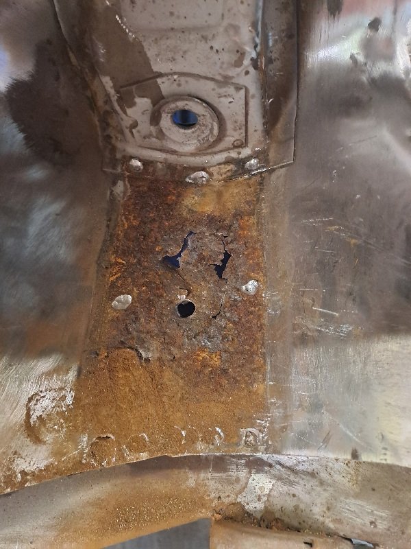
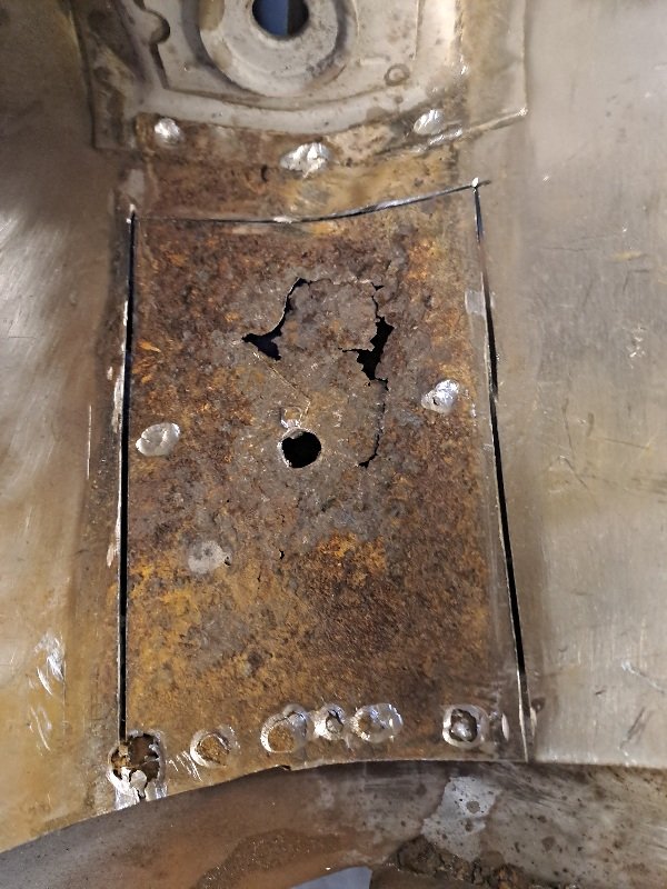
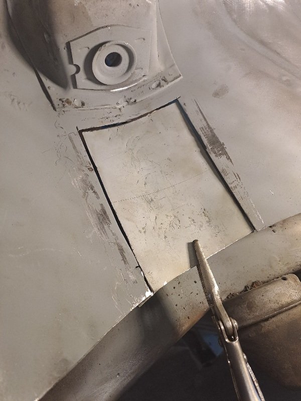
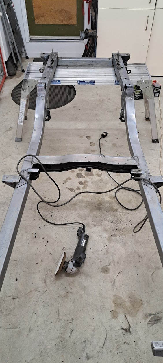
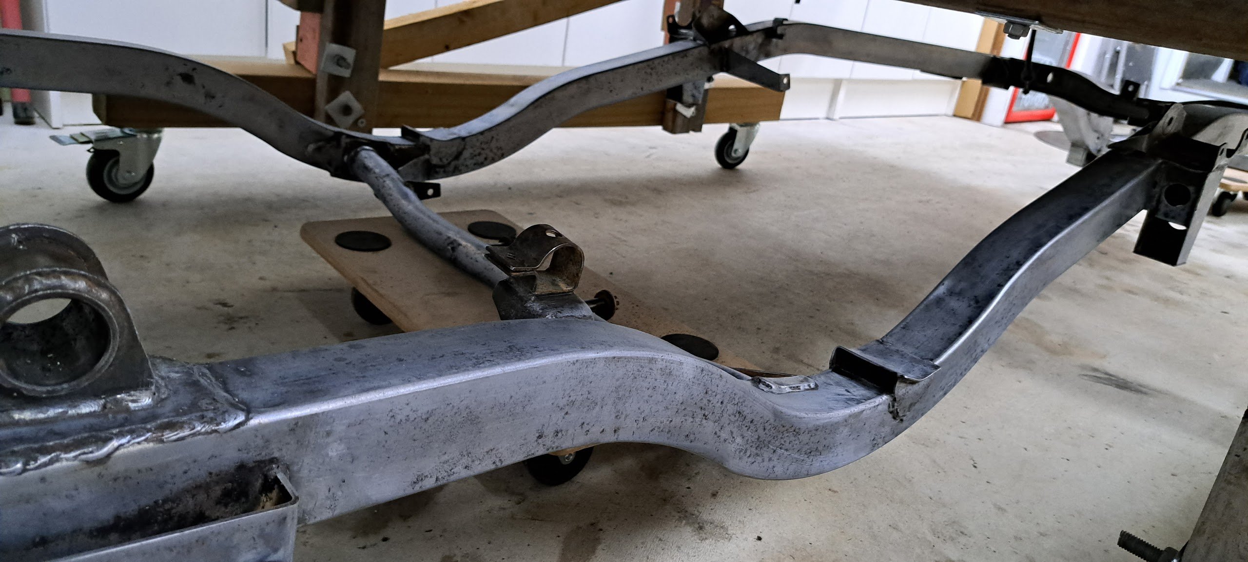
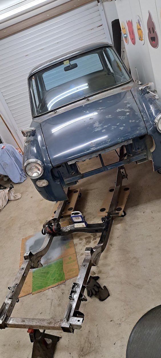
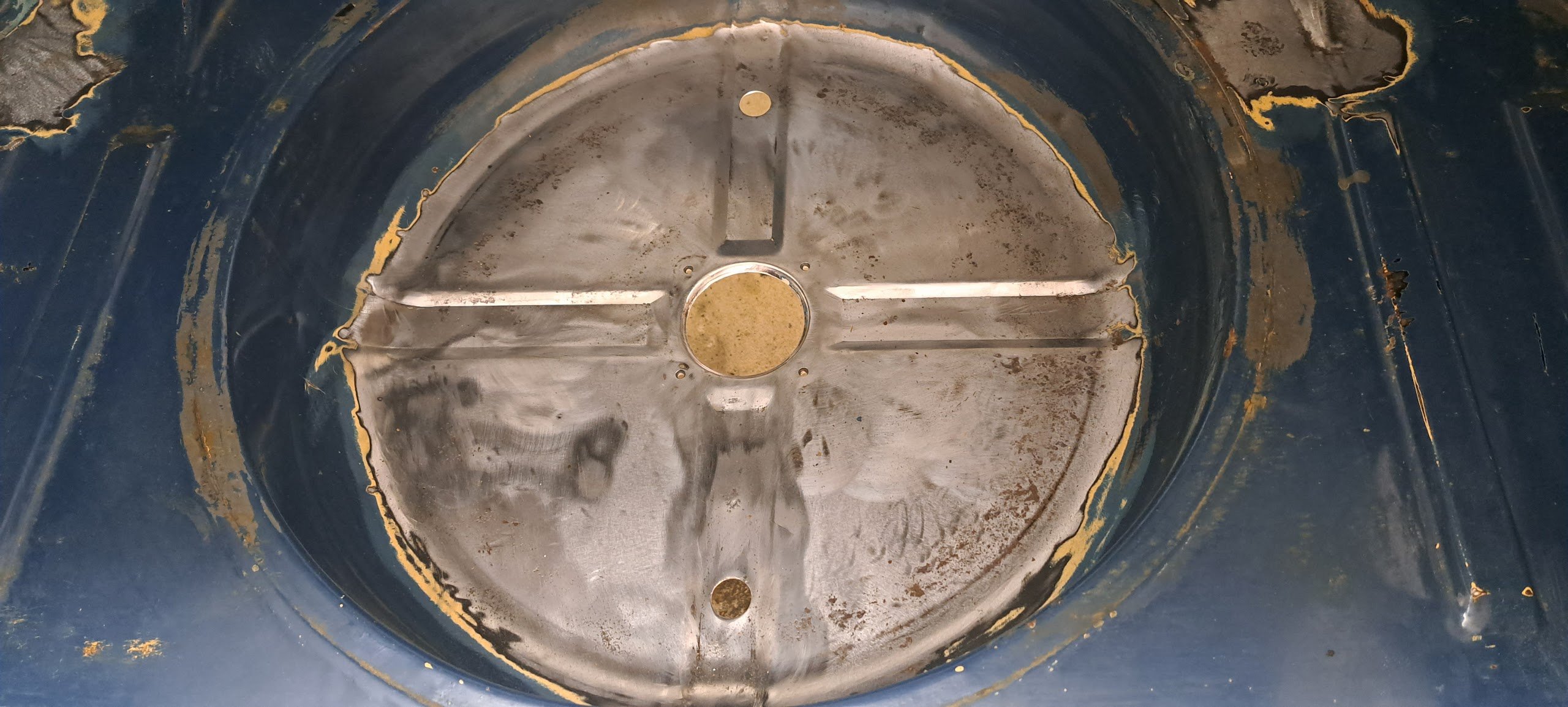
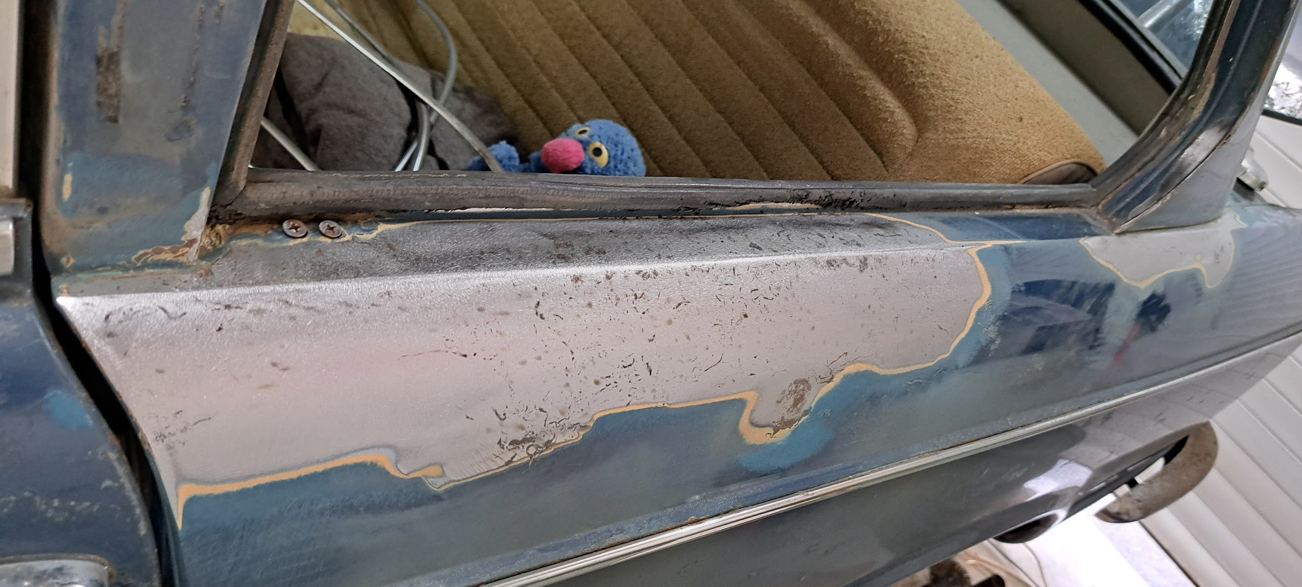
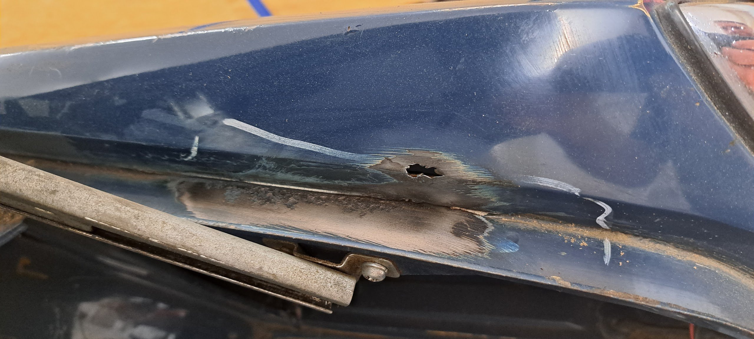
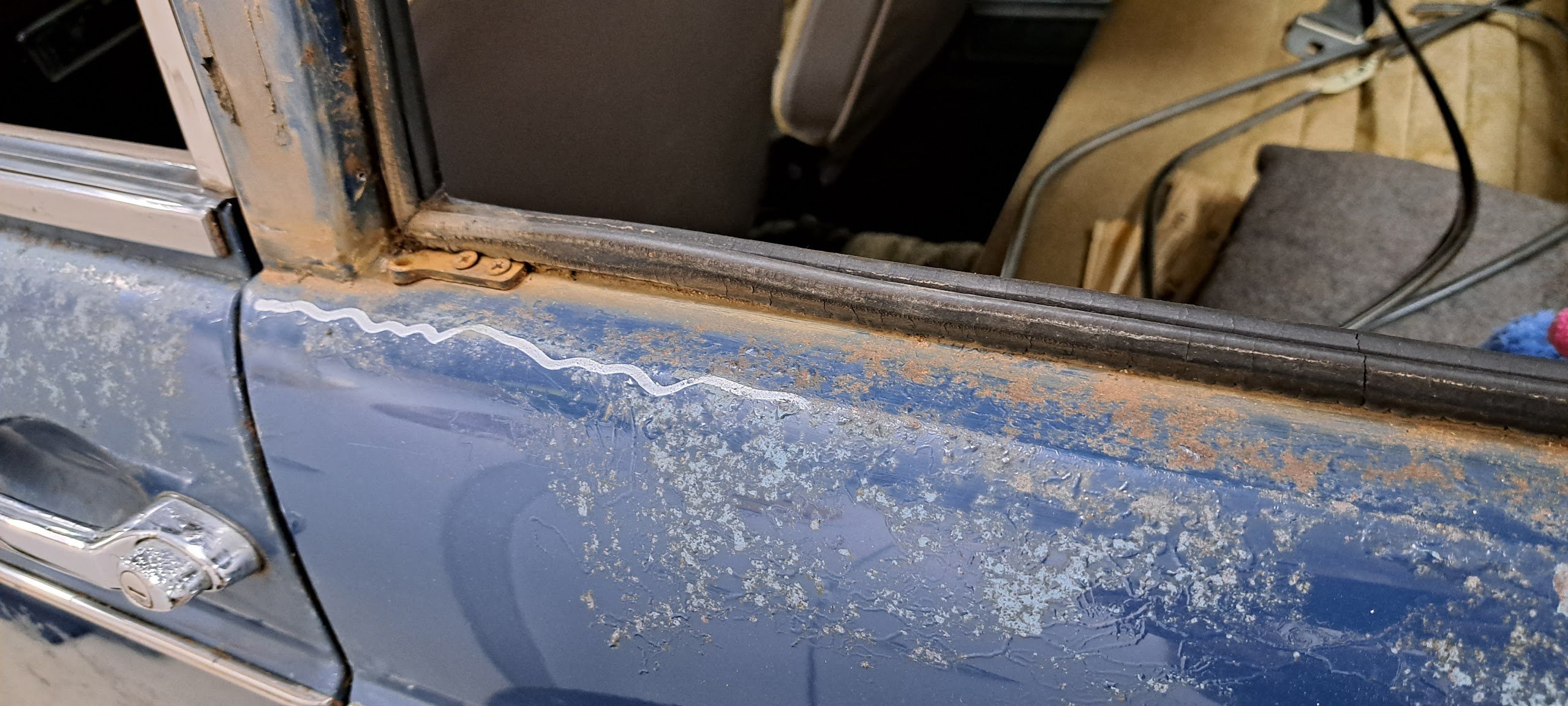
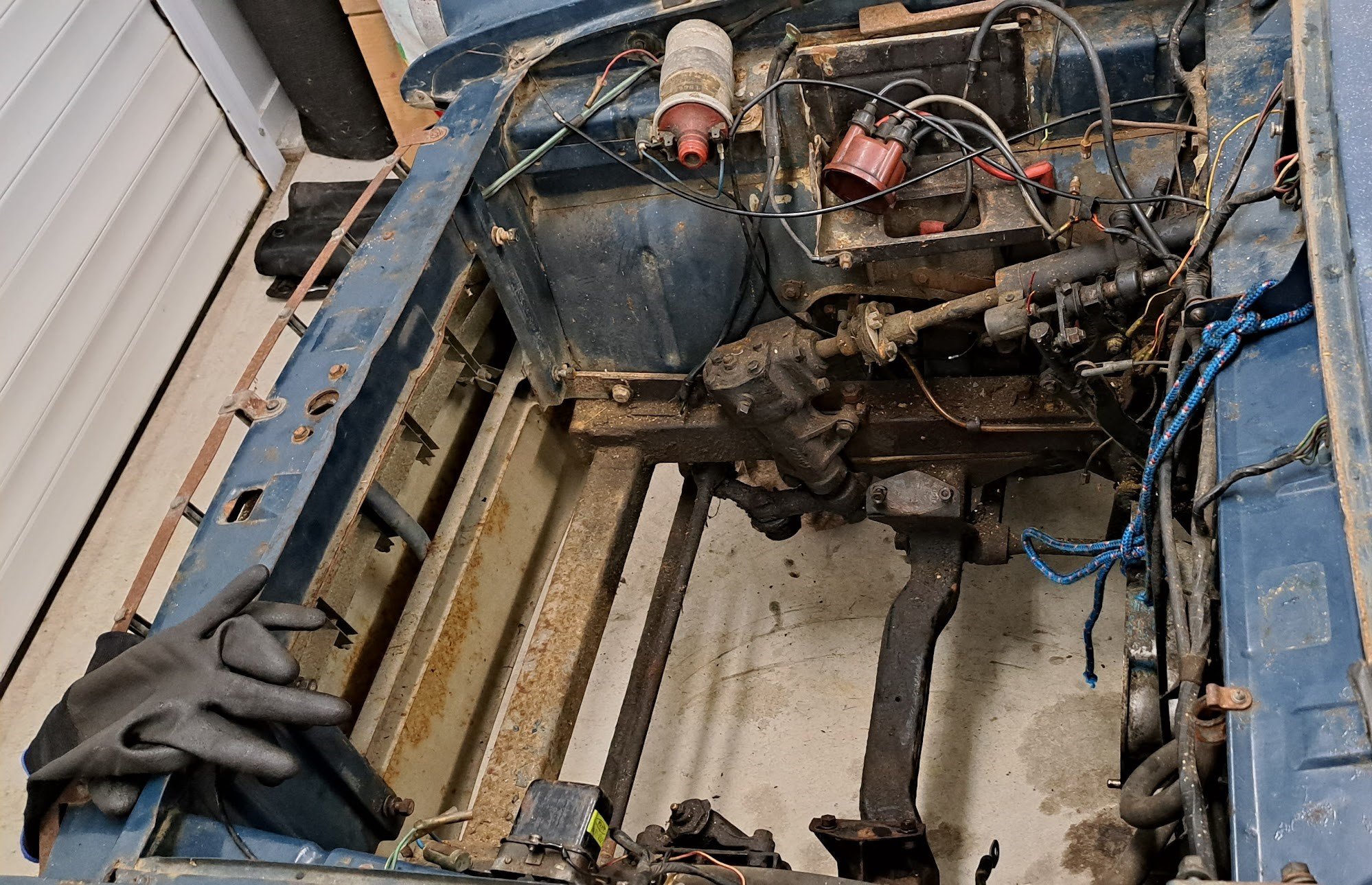
Alternator got sorted thanks to Nick the sparky and his dad. So... the quest for compliance begins.. Main issue is the "rust" which is mostly cosmetic but proving that means stripping off the patina'd paint and proving its not structural. Radiator support panel = mint spare wheel well + patches in the sides of the floor = mint Rear window sill - was dubious about this but = mint And the only rust hole in the entire car so far is this one along the boot lip The shitty thing is the chassis needs a good cleaning - so it is coming off the body and getting a proper blast and paint - work in progress...
1 point
-
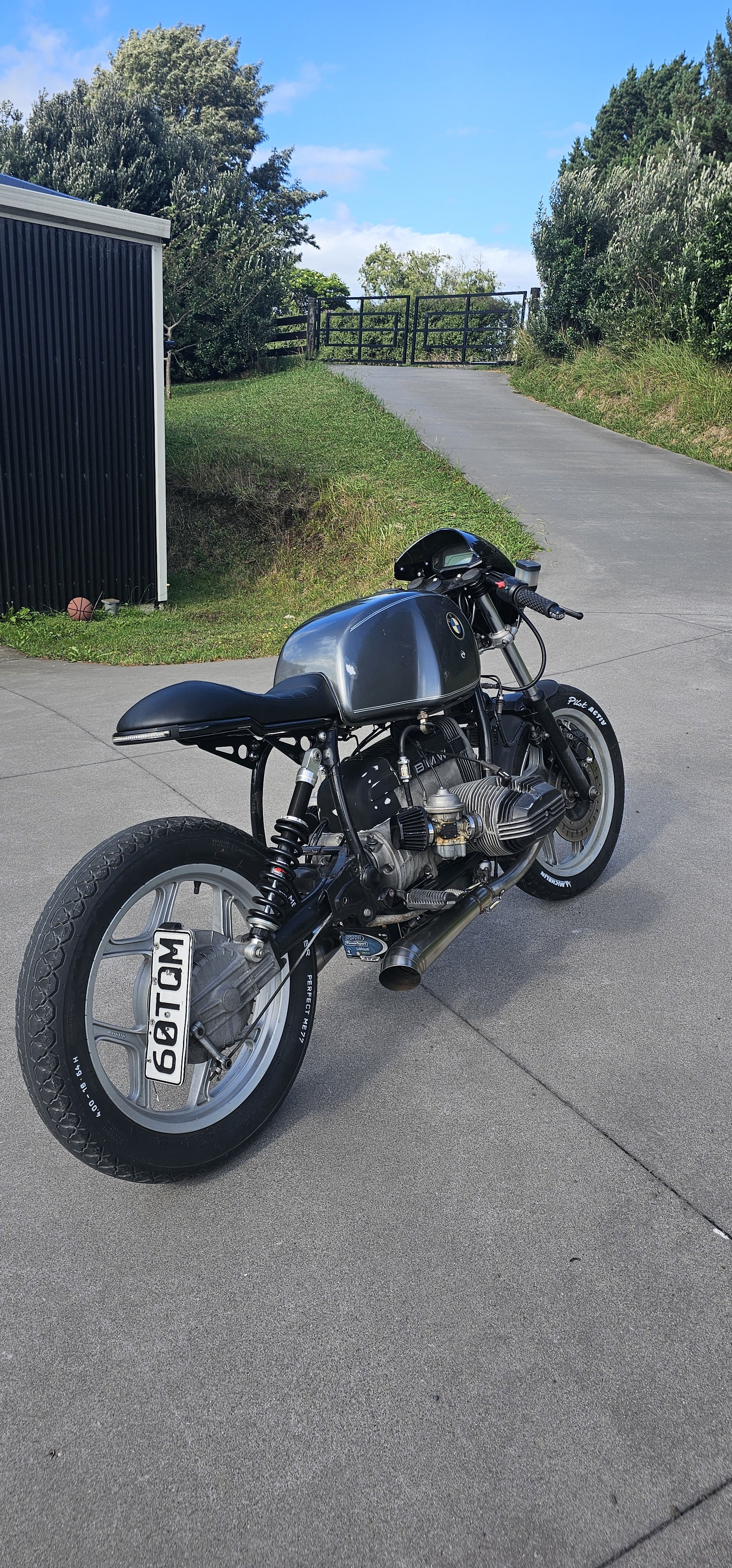
I fixed a couple of fuel leaks and a brake leak. Brake check in the video. Popping is the carb running a little lean without the filter. Alternator Voltage is way way too high at 17v so wont run it too much until that's sorted.1 point
-
It only took 46 years to happen... Tools dropping off the front was a until I realised what it was.1 point
-
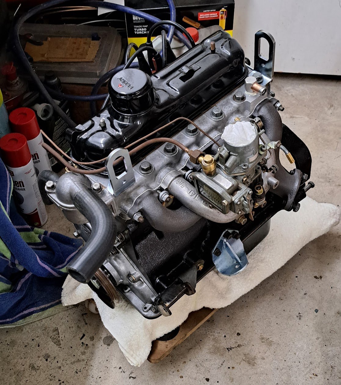
I put a thing in a hole! It took a lot of convincing but got there in the end I was debating what to do with the water pump - but the bearing sounds a bit sketchy so it will be sent off for a rebuild.. all new engine and radiator - don't want it ruined.
1 point
-
Getting there..
1 point
-
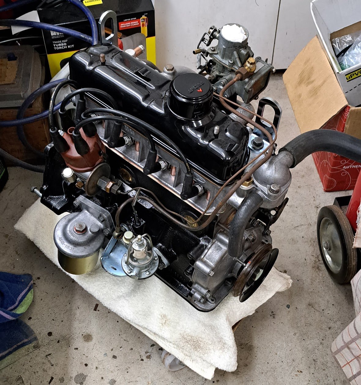
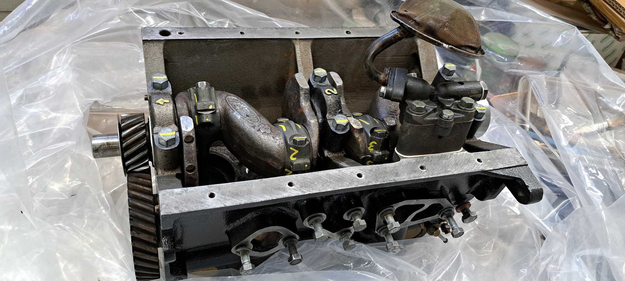
The Big Block is back pushing a whopping 877cc over the factory 797cc. It's also now high compression 9.7:1 vs 9.0:1 I have assembled some of it but awaiting a couple more parts incl the head plus custom head gasket.
1 point
-
Got the horn and number plate light sorted. Number plate was just an earth wire. Horn was the steering column ring absolutely caked in corrosion. Quick buff up and the twins were tooting Promptly blew a headlight - so got them on order. Pulled the fuel tank and found it was absolutely rotten. Not surprising considering it sat 45 years with just a jam jar lid over the filler. New stainless steel one is being fabricated with the help of a local marine tank shop.
1 point
-
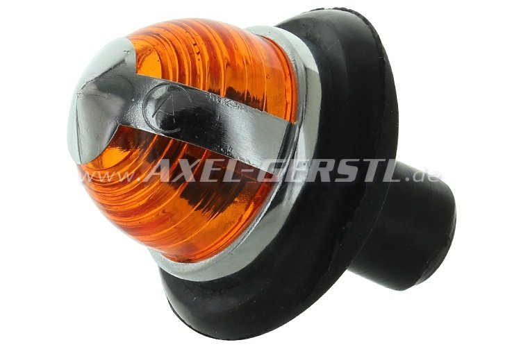
Front suspension and brakes all complete and its back on the ground. Almost ready to add brake fluid and give it real brakes for the 1st time in 45 years engine pistons .. waiting... waiting... waiting... The little side "trafficator" lenses were missing and I spent a great many spare minutes looking through the entire internets for replacements... I finally unearthed an Italian company selling replica Fiat 600 indicator lenses almost the same as the originals. A pair ordered and duly arrived today and were instantly fitted to the original bases ... so happy with this result
1 point
-
Checked the diff and rear suspension when fitting the rear cylinders and found the shocks stuffed and the springs chronically squeaking. so pulled it out cleaned all the crud/dust/rust/oil and added paint. Awaiting an oil seal for the diff and it will all go back in soon with new brakes. new drums have arrived too - they need machining but from all measurements will fit
1 point
-
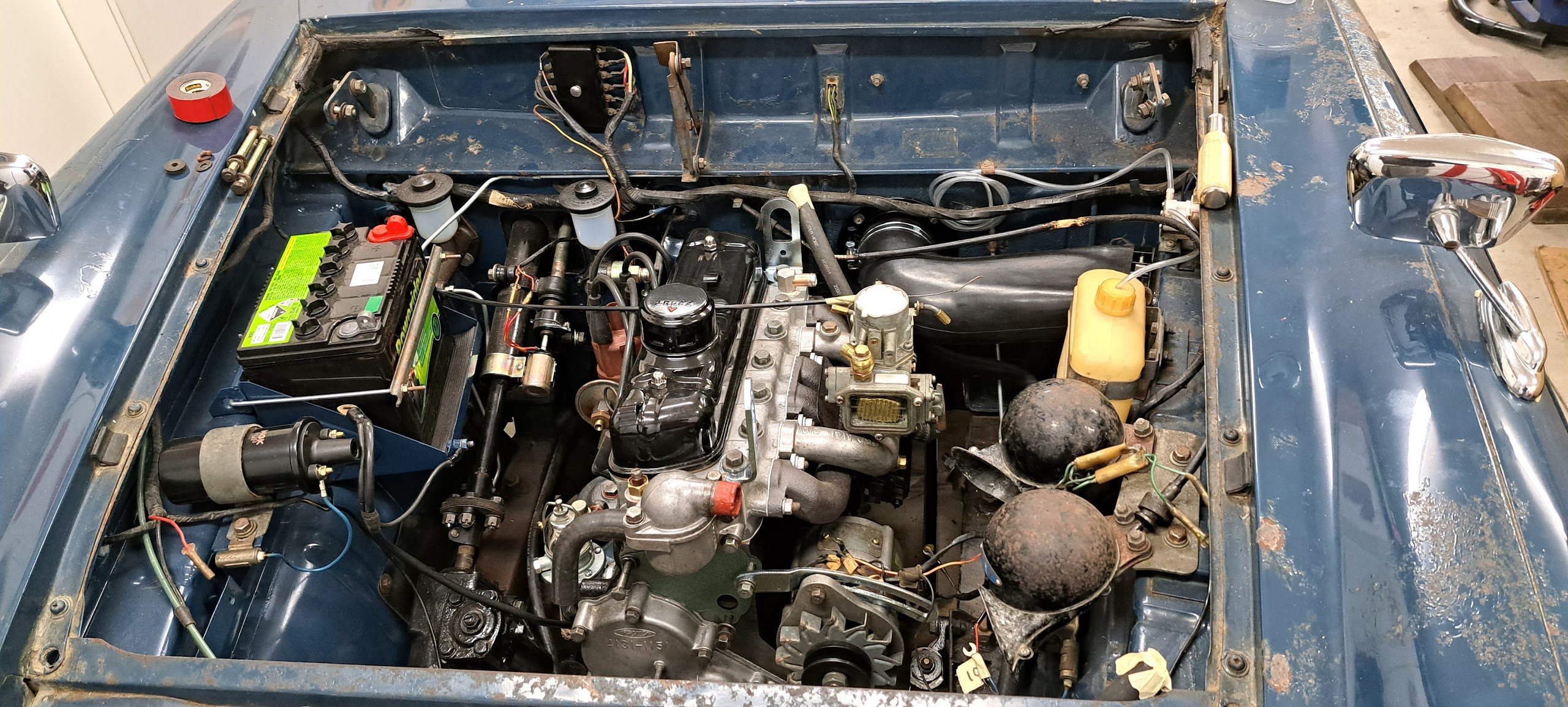
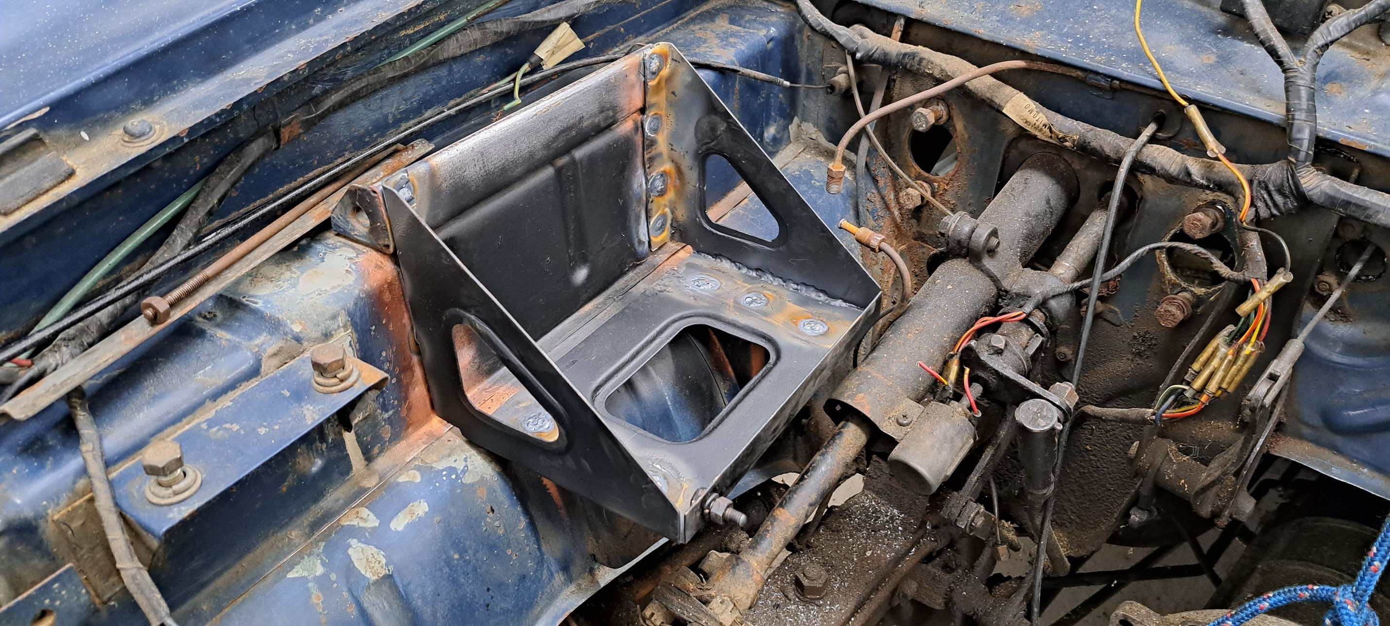
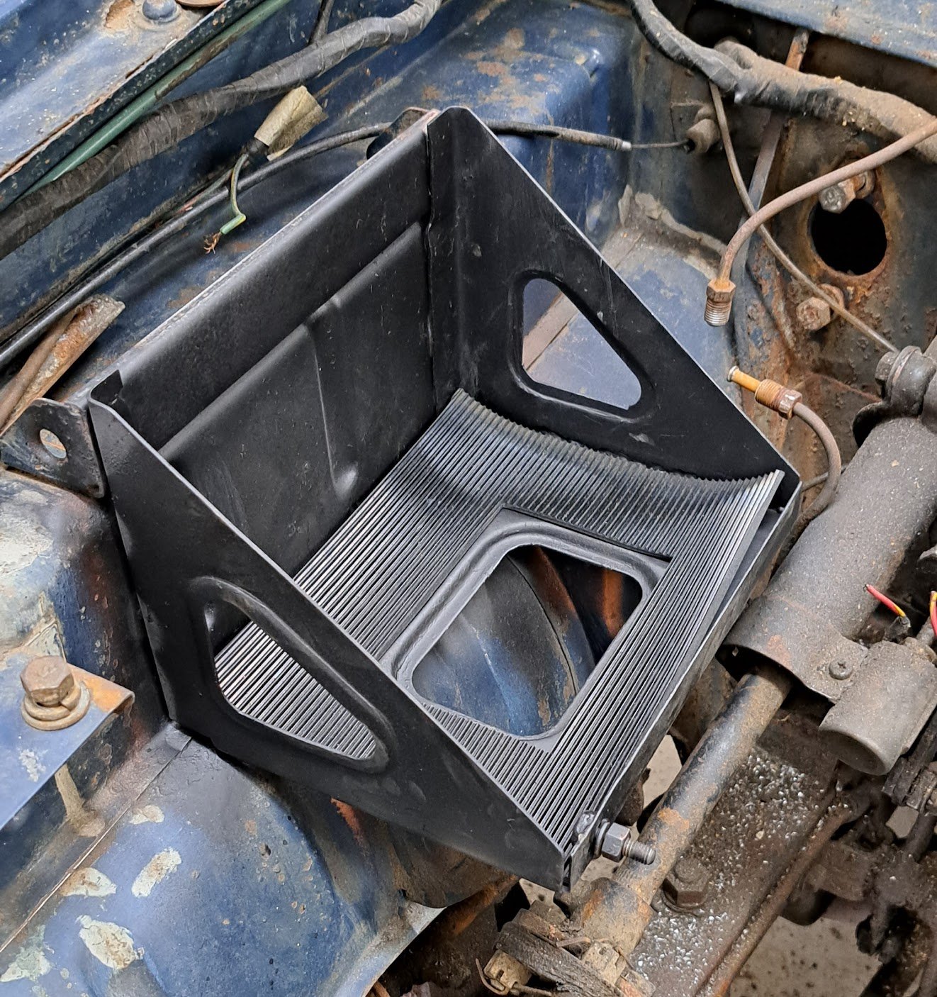
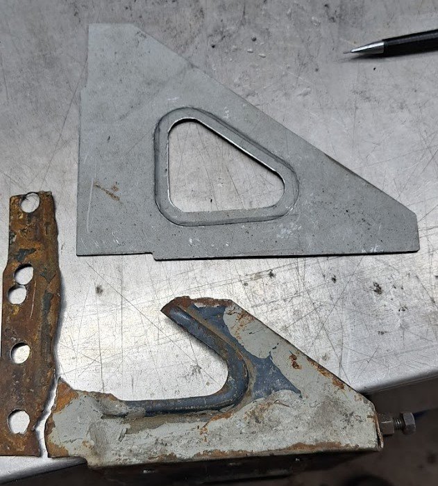
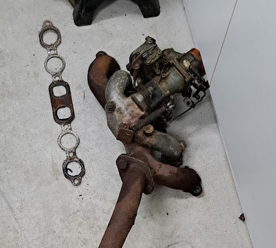
Whilst working on acquiring parts for the motor, i figured tidying up the engine bay is worth doing. Battery tray was mangled in the past to fit a std size battery So removed it Made a template from the remnants and made some new ends and glued it all back together Came out pretty good - i'll get some matched paint and colour it blue at some point Also cleaned up the exhaust/inlet manifolds and gave the carb its 1st bath in 50 years Waiting on a new pump diaphragm otherwise the carb was good condition.
1 point
-
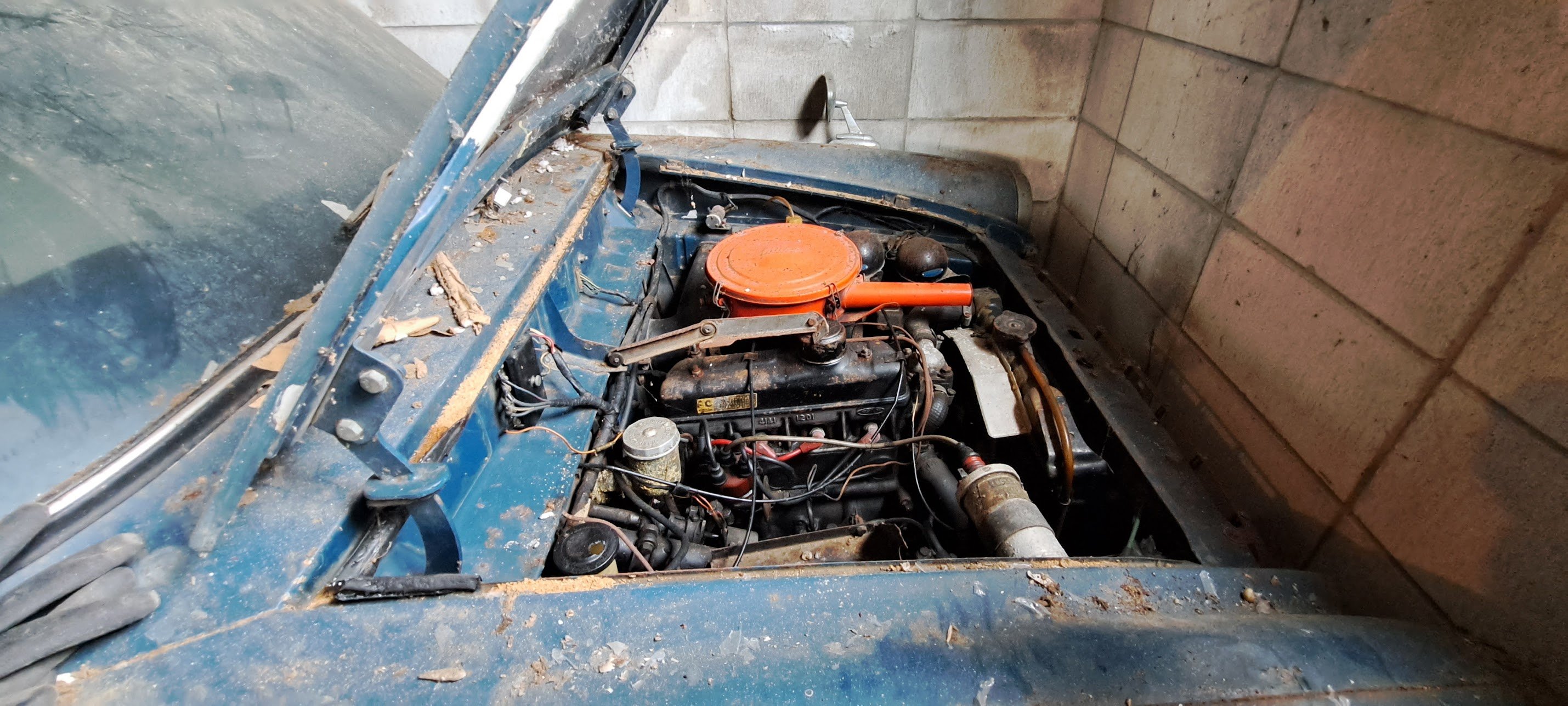
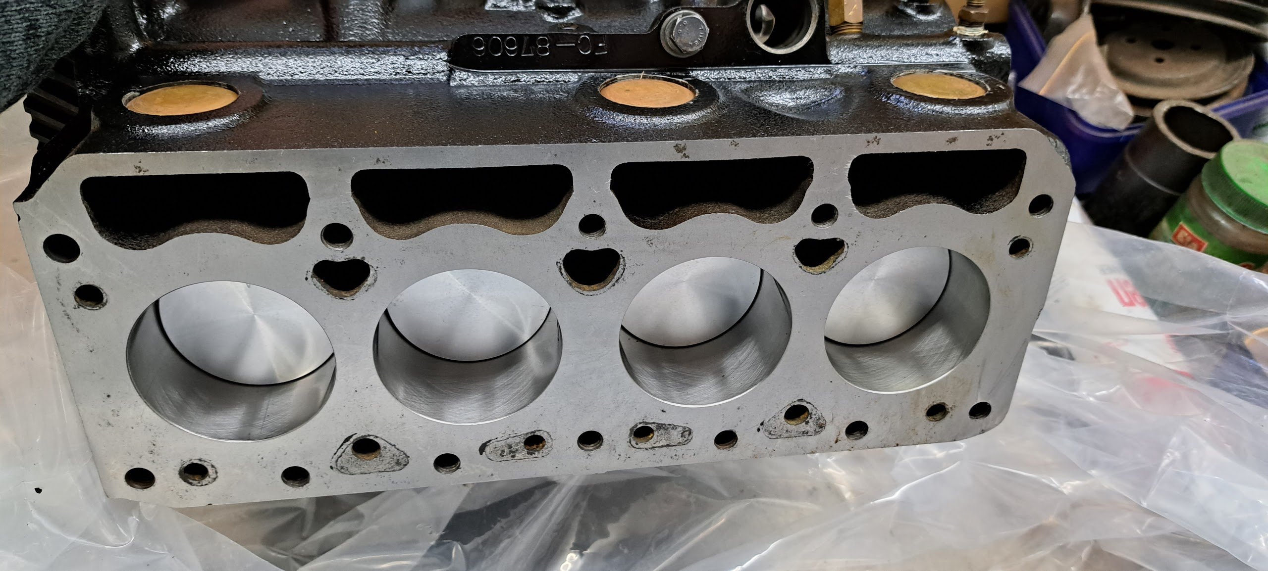
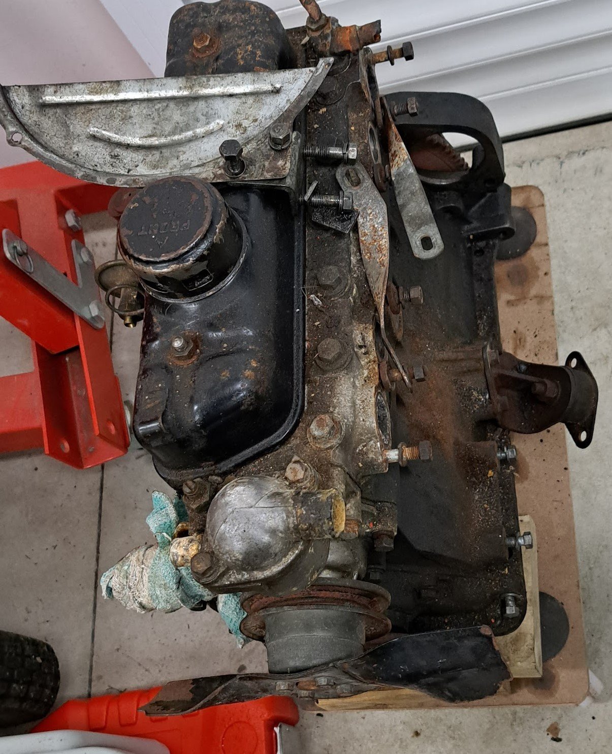
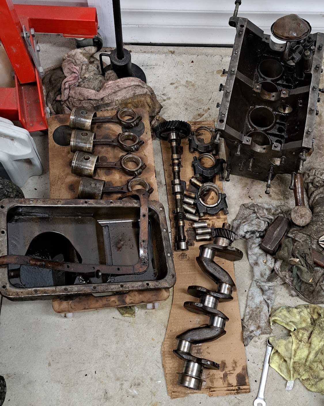
Xmas break.... too much time on my hands... No matter what i did the engine wouldn't budge so i figured it had to come out. and pulled it all apart as the pistons needed some gentle coaxing (BIG HAMMER) to get them out. Plan is to rebuild it with new pistons and bearings plus a tidy up.
1 point
-
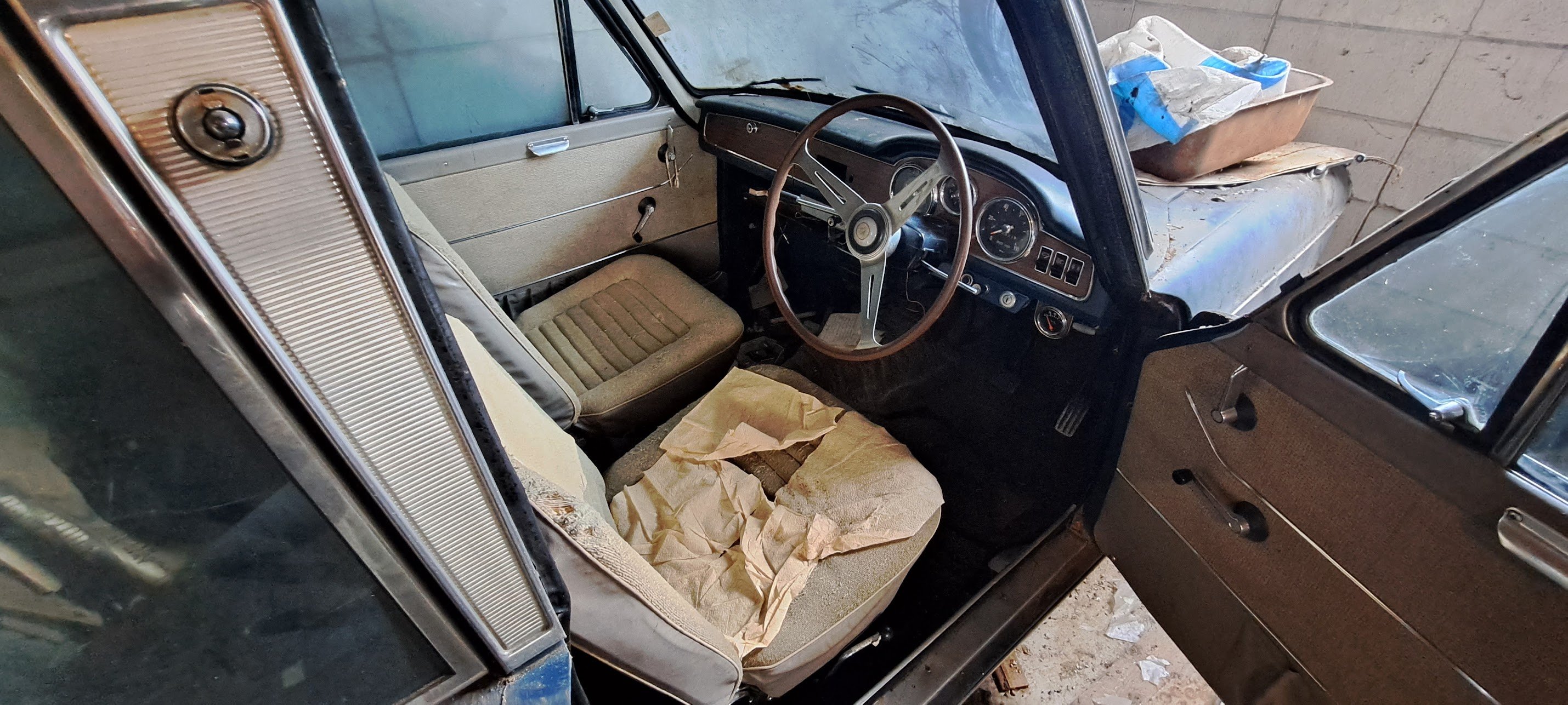
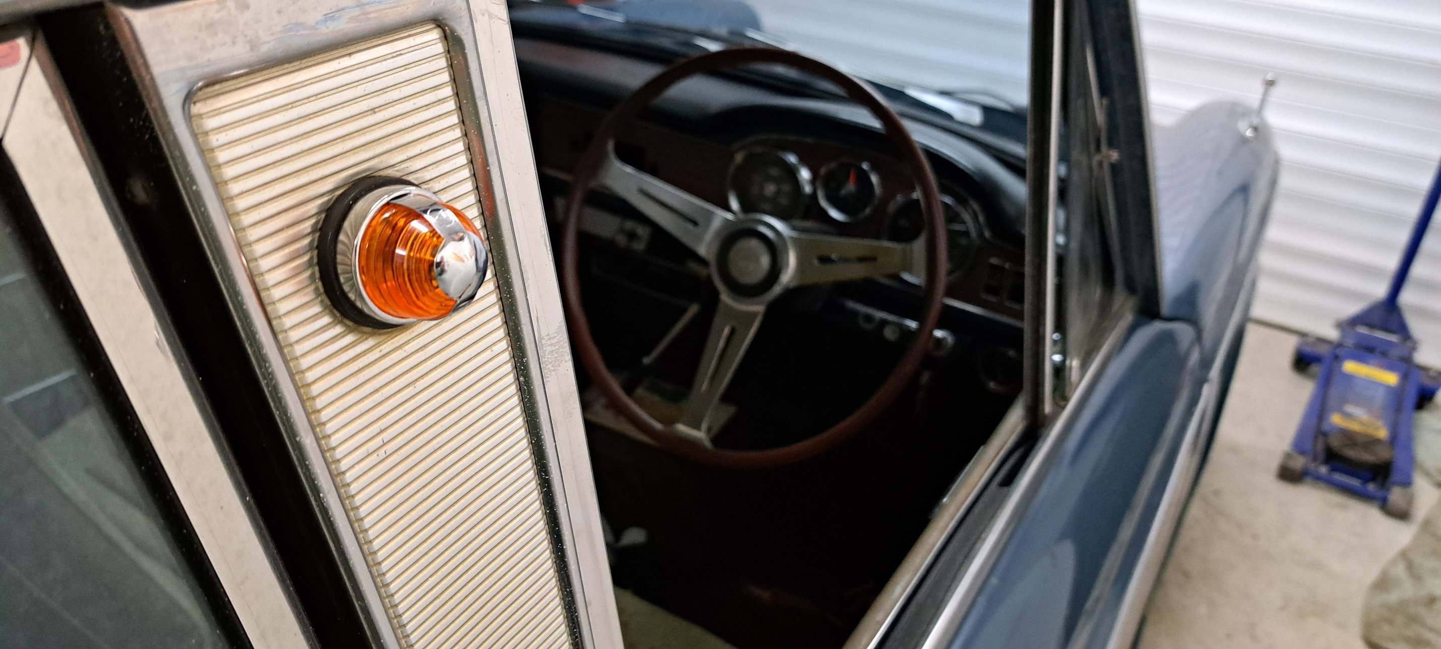
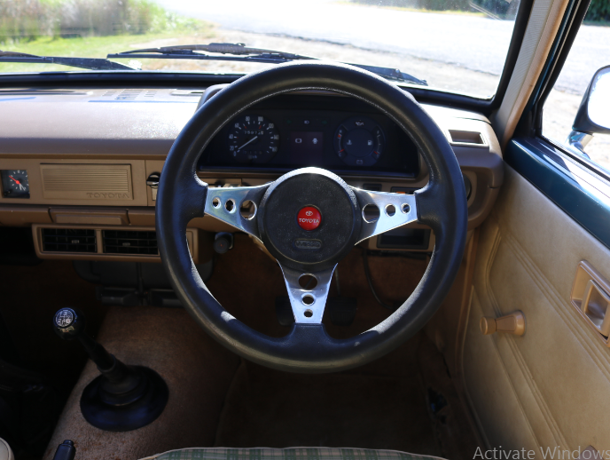
Interior wise I think I will keep modifications to a minimum at this stage. If in the future the scope creeps up, i'll get some period correct front seats and try to match the original pattern as much as possible but for the mean time I did want to do something about the steering wheel. I picked up a wood grain Kaizen steering wheel which I believe (correct me if I am wrong) is from a late 70s early 80s land cruiser and was an optional wheel from factory. The only issue there is I have had a hard time sourcing a horn button that fits. All the ones I have seen for sale at 51mm inside DIA and by calculations I need a 56mm one. If anyone has a toyota horn that suits, i'd love to hear from you. I also managed to get my hands on a Wildcat wheel with a Toyota horn button which suits my application perfectly. I love the feeling of the wild cat, it's small, comfortable to wield and period correct. Fortunately, the wheel came with the boss kit as well which can be hard to come by. I did have to do some minor modifications to it for the horn to work consistently, gave it a good polish and slapped it on. Stiffer suspension, excellent tyres and now a smaller steering wheel has made a world of difference in terms of drivability. A+ would trade again
1 point
-
I got my axles back from the machinist for an unbelievably good price so I can start getting them set up to go back into the diff. I made a start by pressing the brand new bearings on. A handy thing about the skyline axles is they have identical bearing faces to the Falcon axles I got rid of out of my housing. So two brand new Falcon bearings later and I have a fully together diff and a rolling chassis once more. Next, I threw my mockup brake setup on. I quickly noticed a problem when I went to bolt the wheel on. The caliper actually sticks out further than the wheel mounting face. I'm not exactly sure how the Mondeo wheel looks, but I'm getting the idea that it must have a bit of offset with a mounting face the same diameter as the brake disk. The Cheviot Turbos that I have have a mounting face that is bigger than the brake disk face, so it doesn't sit down properly. My best solution for this is a 10mm wheel spacer. I made a mockup out of MDF to test my hypothesis. According to the Hobby Car bible, this would meet almost all the requirements of a wheel spacer. It also has the bonus effect of making the wheel hub-centric, because the turbos have a larger center hole than the standard Escort sized hub spigot and are do not transfer the load to it on a normal English diff. The only thing I'm not sure of is the requirement for the spacer to "be set-screwed or attached by another secure mechanical method to either the wheel or hub face." Does the fact that it is clamped by the wheel nuts not cover this? Or would I have to drill and tap countersunk screws into the mounting face of the wheel to ensure they are compliant? In any case, I threw the mockup spacer on to check fitments. Here you can see that it provides a mounting face with sufficient clearance to the caliper. And the hub centric support: In the final version, I would probably make the center a blind hole that sits snugly over the axle spigot for extra support. And finally, the wheels fill out the arch much better in my opinion with just that 10mm extra track width per side. And with the center caps on, you'd never know the difference. While typing all this, I had the thought that Mondeo front disks may have a different offset between the braking face and wheel mounting face which may solve this whole thing. It wouldn't solve the hub concentricity issues though. I think I'll still go to the wreckers and have a look but I'm open to suggestions. Cheers.1 point
-
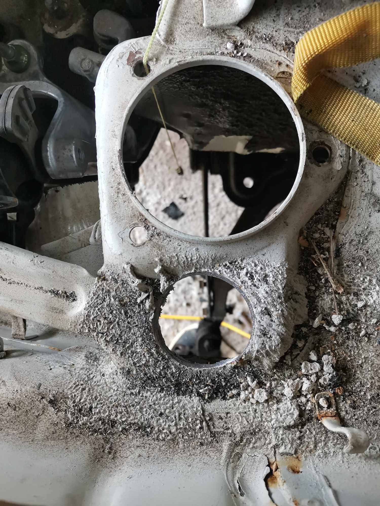
I wasn't completely happy with using bolts with each mounting flange being tapped to hold each throttle body on. Not least because all my untamed strength acting on the quarter inch ratchet managed to strip one of the alloy tapped holes on the first try. So I decided to swap the whole lot for steel studs pressed in from the back side of the flanges. So, two minutes of turning later... You get these delightful little fellows: And then pressed into place. Which gives me a much more professional looking nut rather than bolt with a neat little button head on the back. While I was in there I also added an extra throttle return spring. I'm much happier with the throttle now. I wasn't quite returning to its seat after lifting from light throttle but now it snaps shut far more satisfactorily. Next job is at the other end of the car...1 point

.jpg.9298a81b37527e20991ea9282033a829.jpg)


.thumb.jpeg.e0a4bff61111e0c8c7396950fcc94da1.jpeg)


This leaderboard is set to Auckland/GMT+12:00