
Leaderboard


Popular Content
Showing content with the highest reputation on 03/15/24 in all areas
-
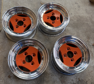
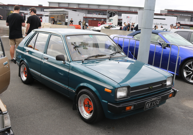
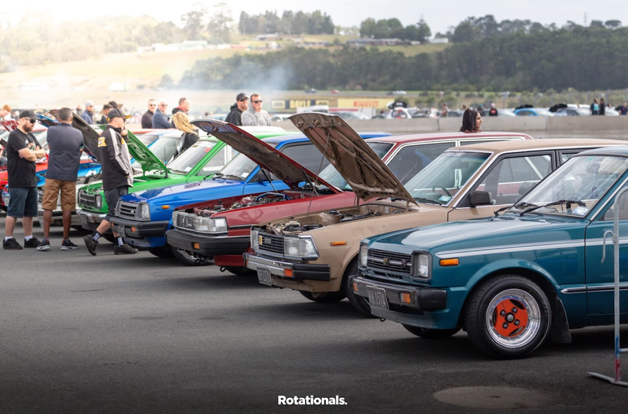
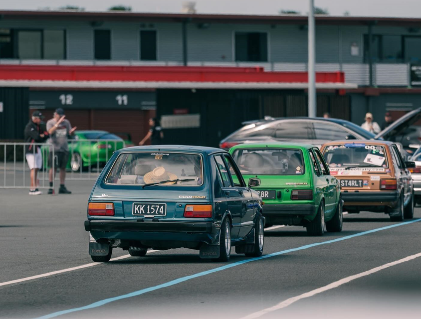
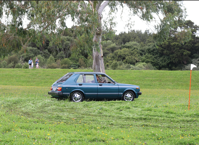
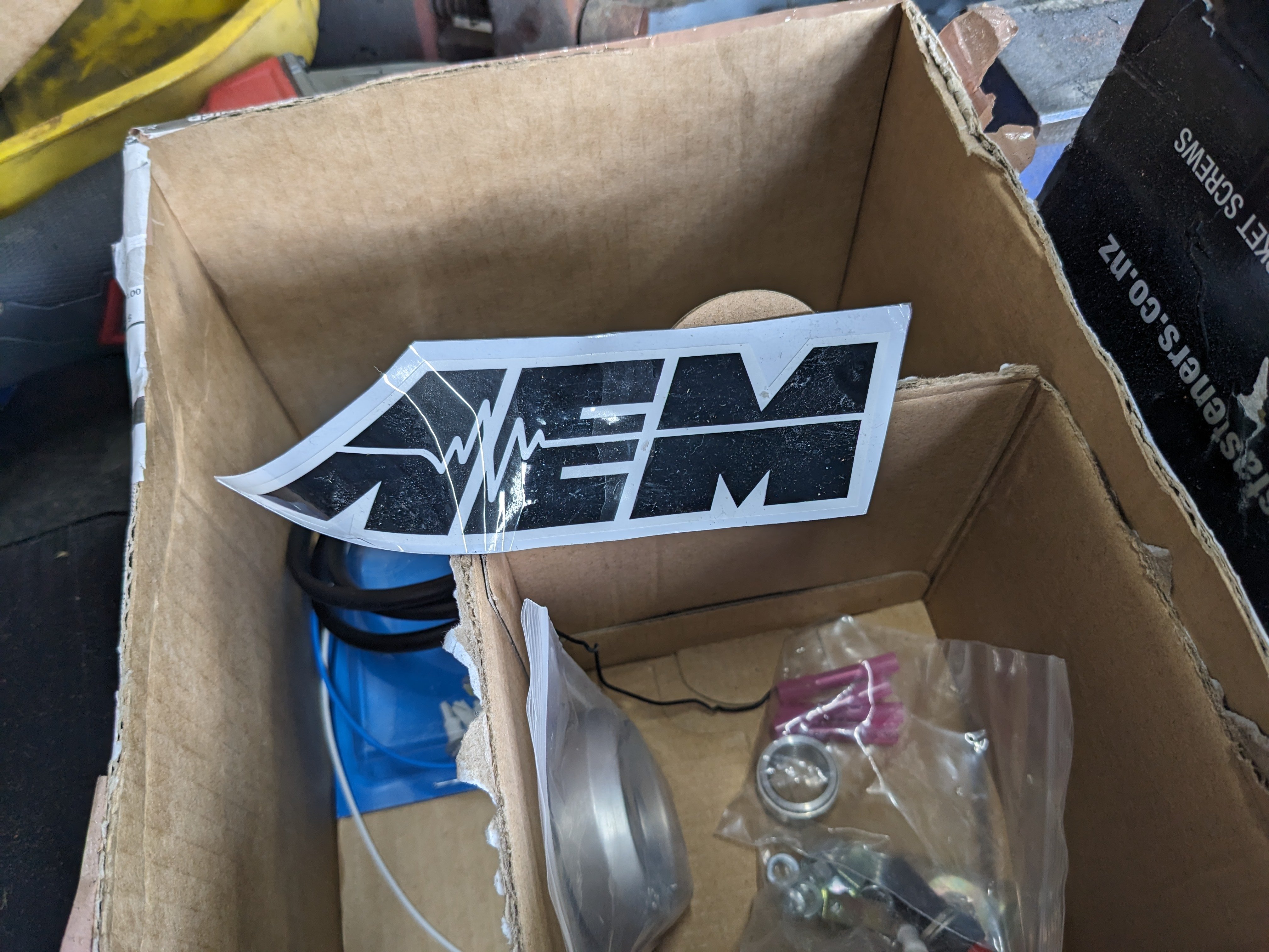
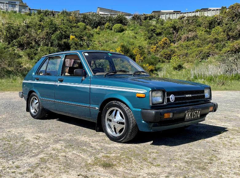
I have always loved Advan A3As and I managed to I pick up a set of 13x6s. I got the lips fixed, painted the centres and convinced the bro to polish them for me (not a member but cheers mate). Orange and blue is a sharp contrast, but it's grown on me Which brings us now back to first sentence of the previous post. I've just driven this from Wellington to Horopito to Toyota Fest at Hampton downs and back (1300 kms) with a couple of mates. There were a couple of small issues with the KP on the trip but those were quickly and easily rectified. It might be slow, but it got there ha } Have a squiz the oldschool.co.nz sticker I got over a decade ago and never used until now. That's all for now
 16 points
 -
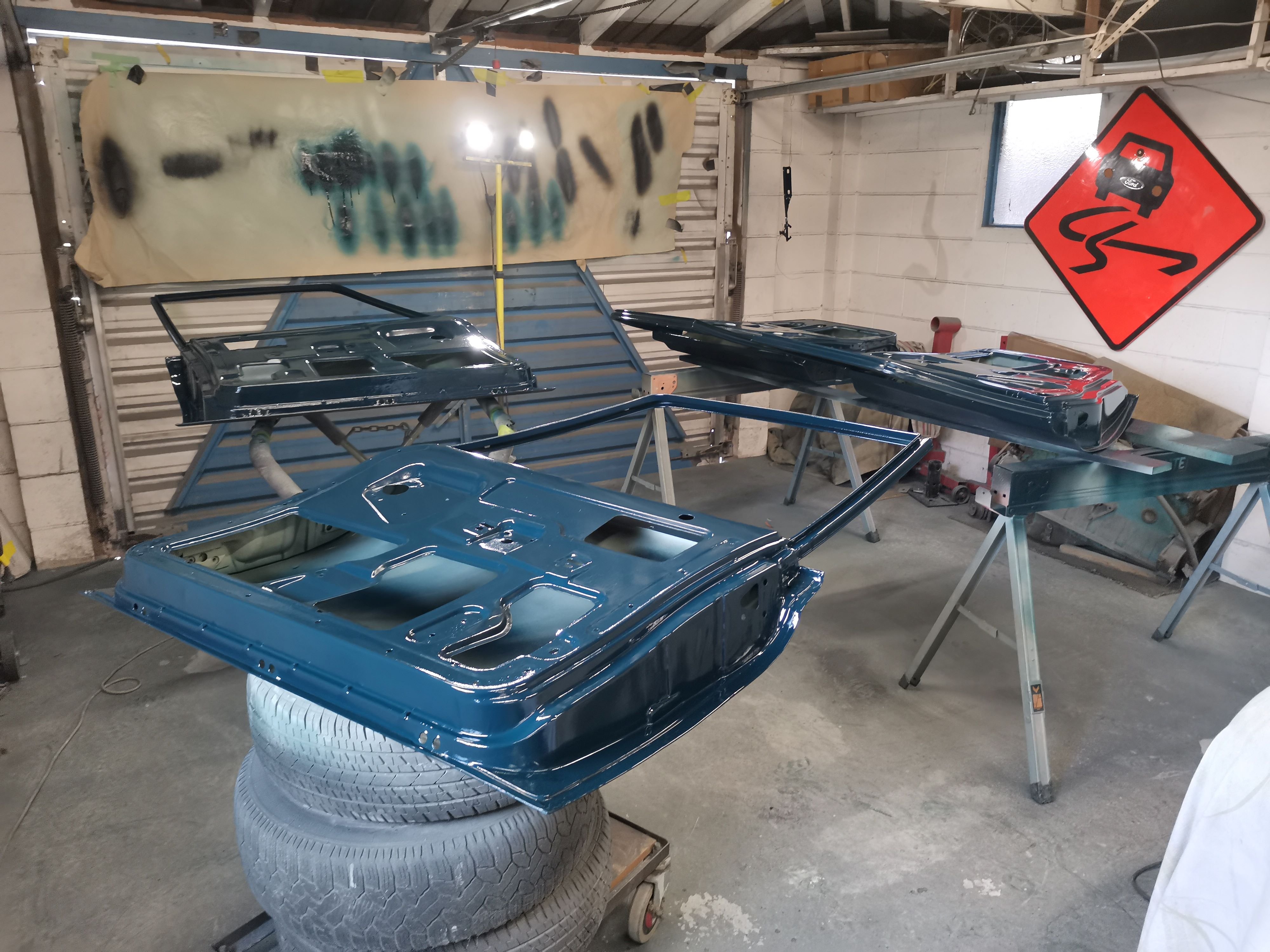
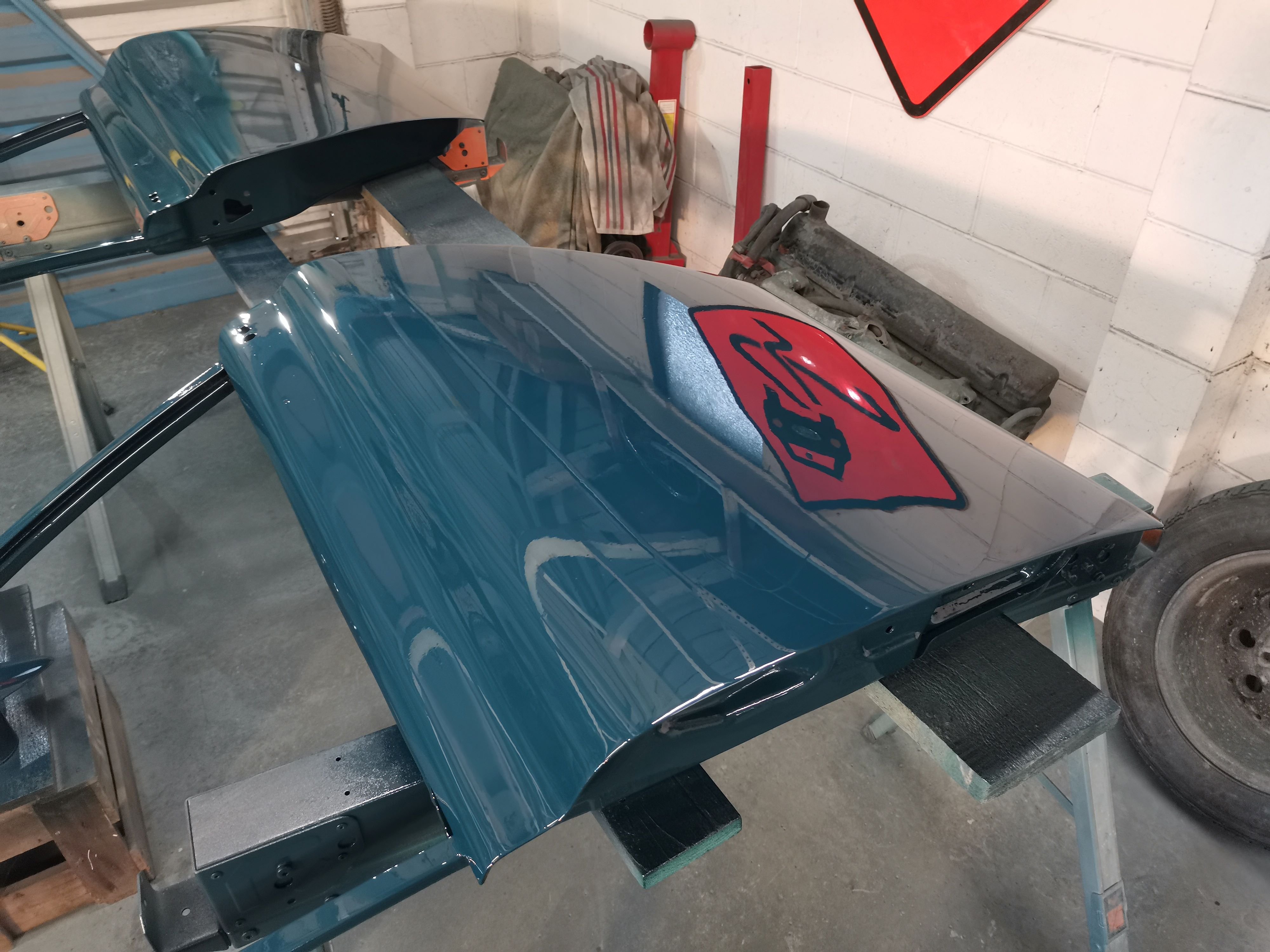
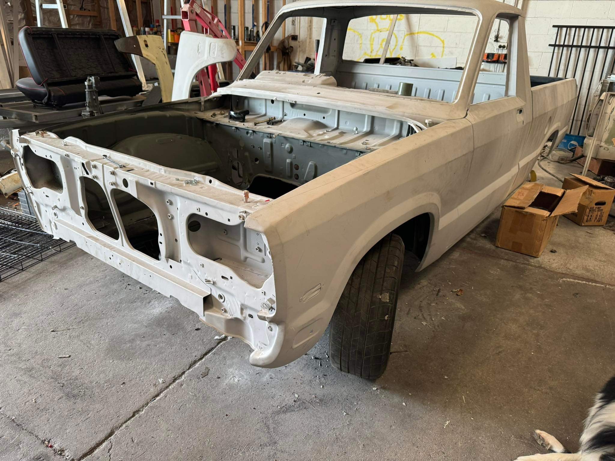
The door with the plasma cutting was pretty wonky, so ended up finding a replacement. Managed to get all of the doors paneled and into paint. A bit of dust and a couple of runs, but I'm definitely getting better with the paint gun. Now working on sandblasting the door hinges and cleaning up the boot lid, before reassembly, wet-dry sanding and a final coat. Stoked to be making some good progress again.
15 points
-
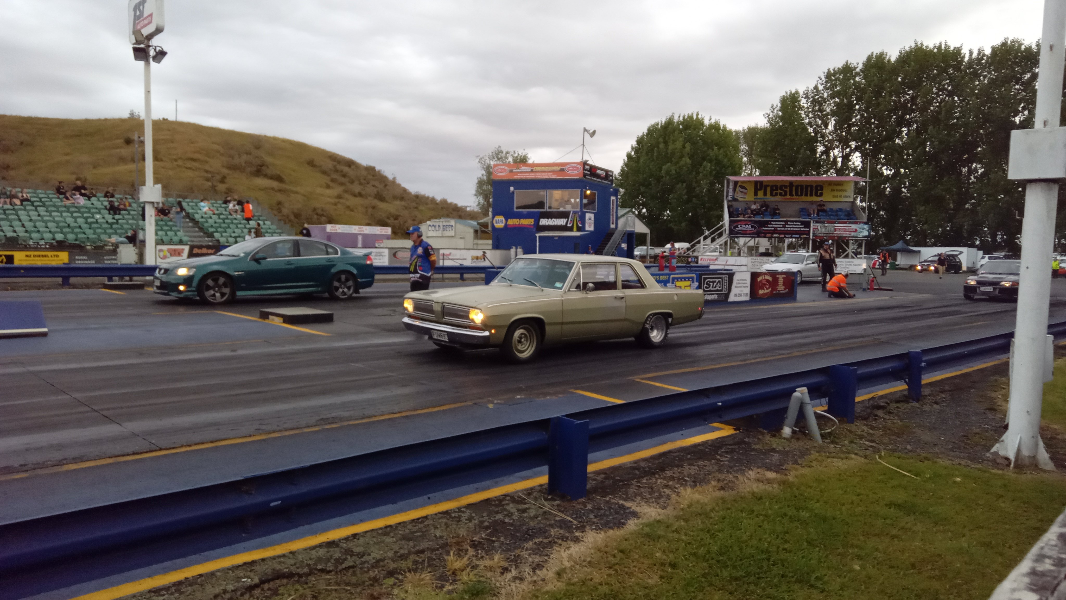
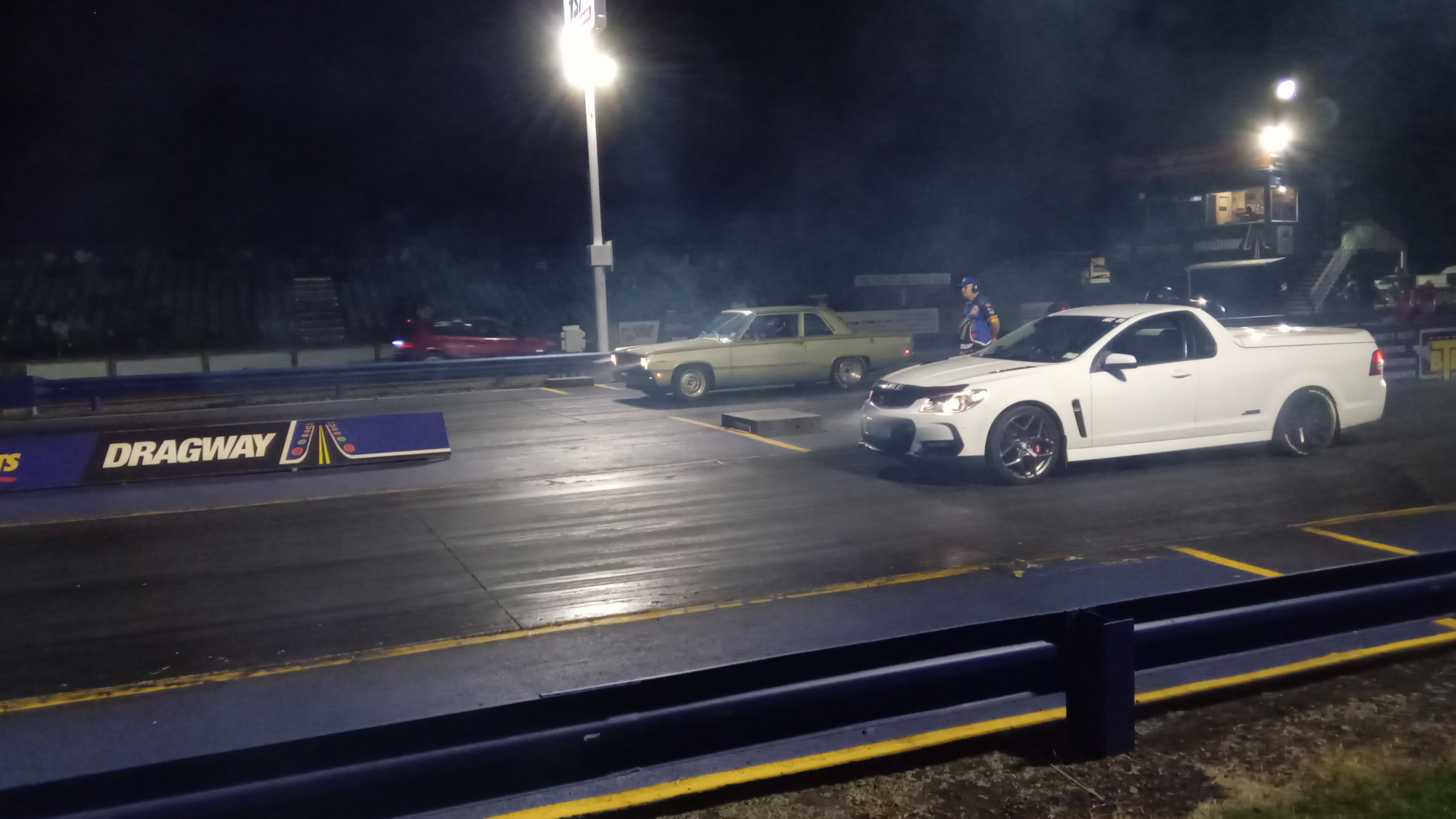
New springs made it more consistent,although slightly slower. Different wheels and muffler off when it did the 11.35 previously 11.5@118 every pass I have turned the 2 step rev limit down slightly as it was having trouble holding on the brake which I can probably fiddle with to improve I'd like to get it down to 11.0 so it's more competitive at the night drags https://m.youtube.com/watch?v=kdfGgT2pKHw&pp=ygUMVW5kZXJjYXJ2aWV3
9 points
-
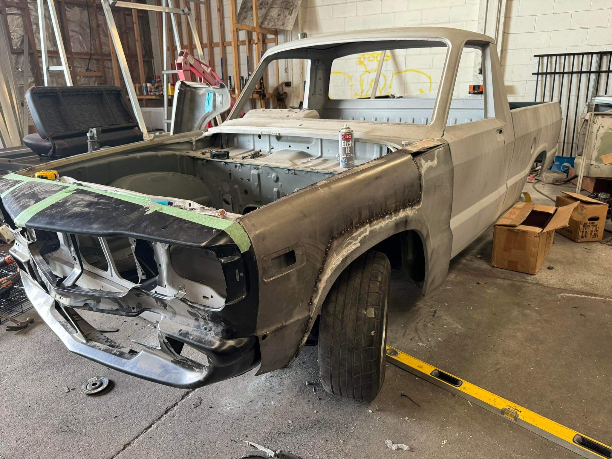
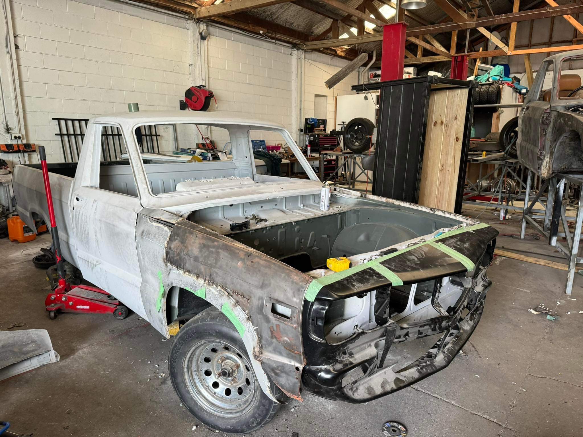
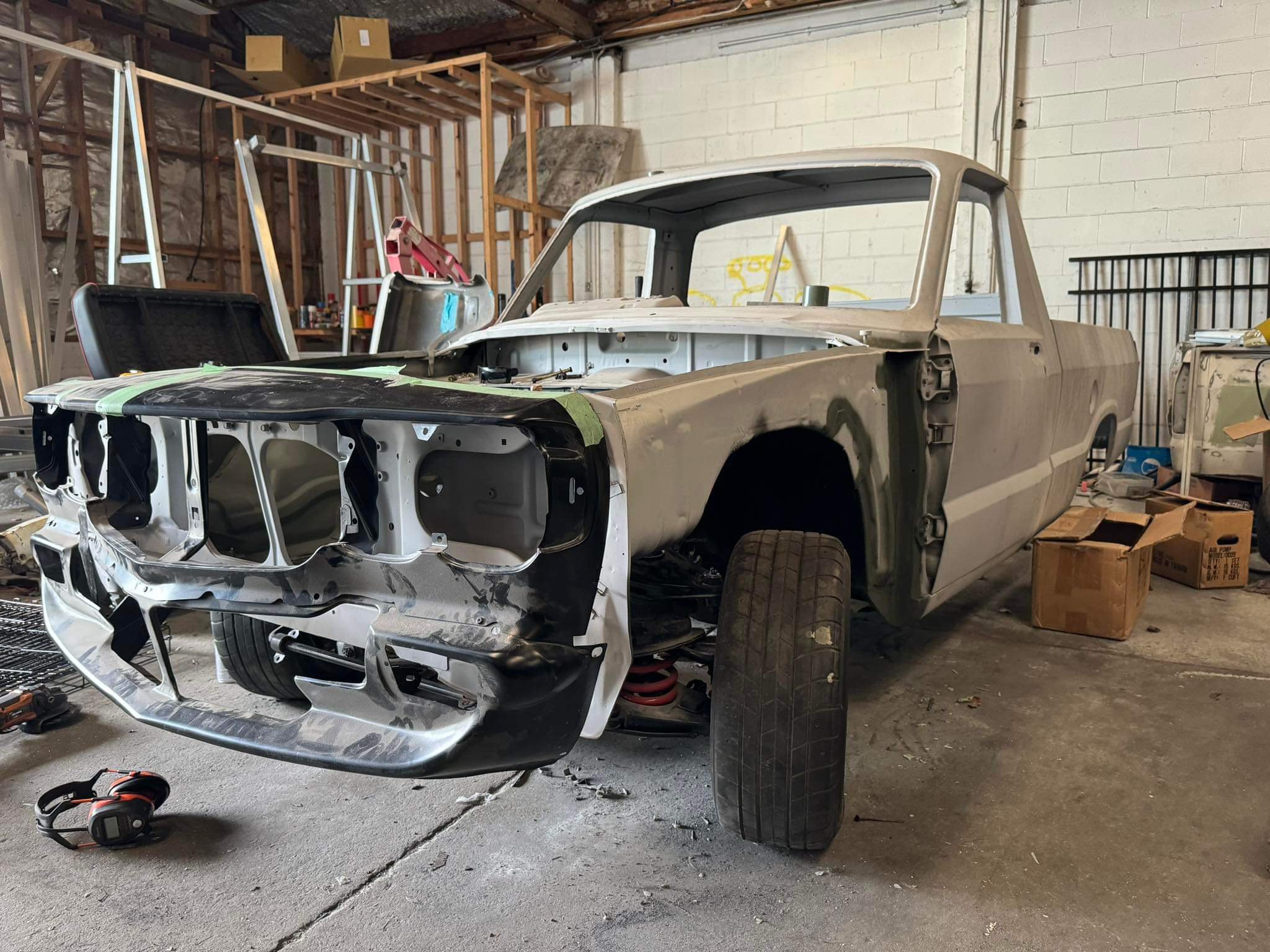
Nosecone is fully mounted, rough guards are on for mock up. this ute seems to be longer than the other ute. Probably built in a different factory as they are 4 years apart from memory.. im glad I chose to use this ute for RX3UTE, it is the same model and spec now.
8 points
-
Big step forward. Rest of the stuff can be drip fed, as and when I feel like doing it.
5 points
-
Regards the driveshafts. I chatted to my hotrod friend, ran the two ideas I had come up with and he suggested an even neater, stronger, failsafe way to do it. But I had to get another pair of scooby shafts because I'd already chopped the ones I had down in length I won't go into details here because I'll spend enough time doing that in the build thread but I'm super happy with the results. As for fuel tank, yeah since I've added a bolt down hatch to place the pump inside is now modified so I'll look for a suitable plastic box* for the battery (it's quite small though) I can't line my alloy box because I made it to suit the battery and it's bloody snug in there. I could line the outside but it would end up messy I bet. *off Alex goes - rummaging through the Sistema range of kitchenware/fuel tank/battery boxes at the warehouse.4 points
-
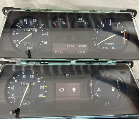
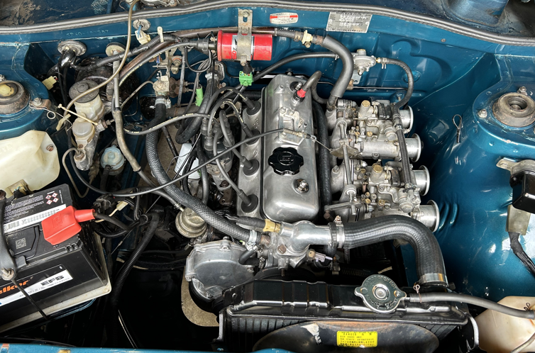
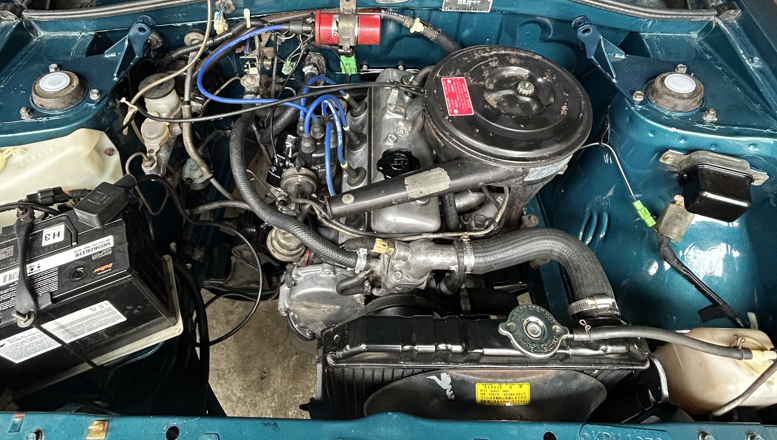
I've just driven this on a 1300 km round trip so I am feeling inspired to talk shit about it but more on that later. Jeepers, it's been a few WOFs since the last post.. I'll sum up the last couple years.. I did a grass auto cross, it was a hoot I changed the cluster for a rev gauge one (shout out to Matt for the wiring diagram. that would have taken me far too long to figure out) The inevitable happened, and the 2k just wasn't cutting it anymore so I started to build a 5k (got a cheap van, drove it home and pulled the motor). While I was building it, a well used 5k came up for sale locally and for what it came with, it was too good of a price not to grab. I gave it a birthday, put that in, blew the head gasket driving home from getting it tuned, replaced the head gasket and then had a few months dorting around. I was told all the classic yarns when I got it.. bored block, ported 3kb head, oversized valves, massive cam, high compression etc. Which surprisingly, were true. Unfortunately the lifter prolapsed. With my tail between my legs I ripped the trusty 2k out from under the house, gave it a spray can rebuild and put it back in place.
3 points
-
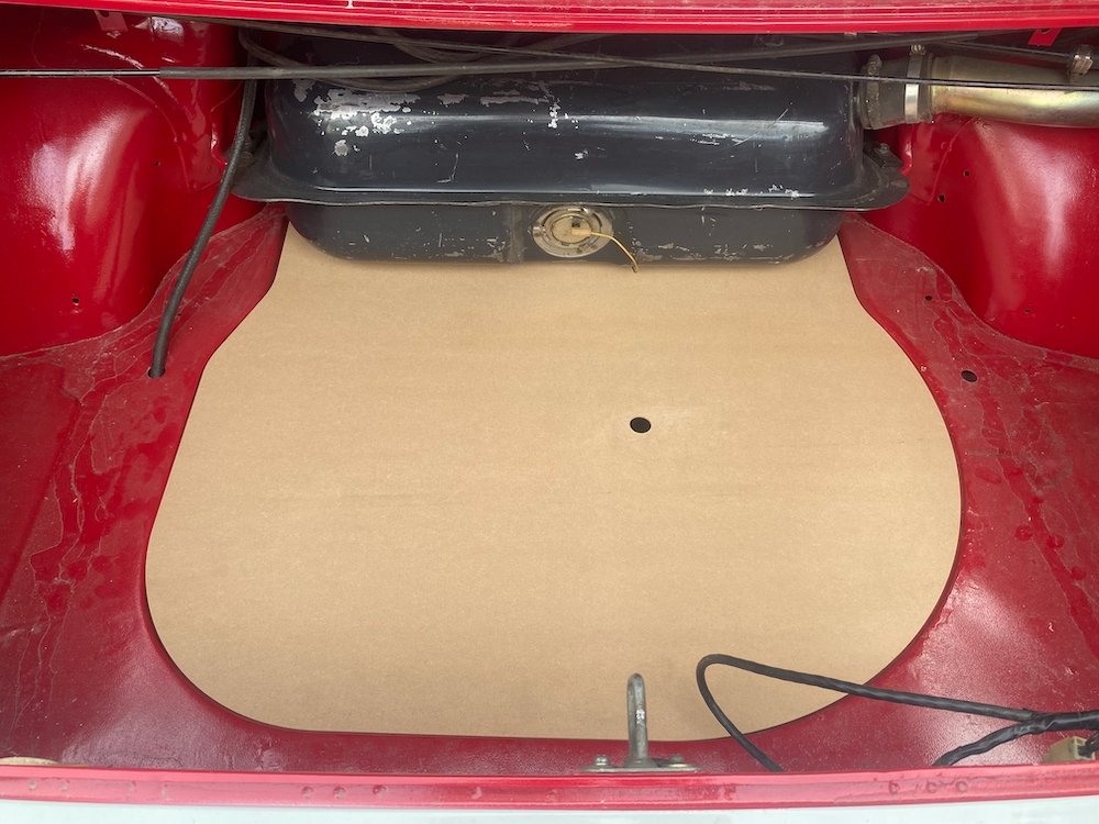
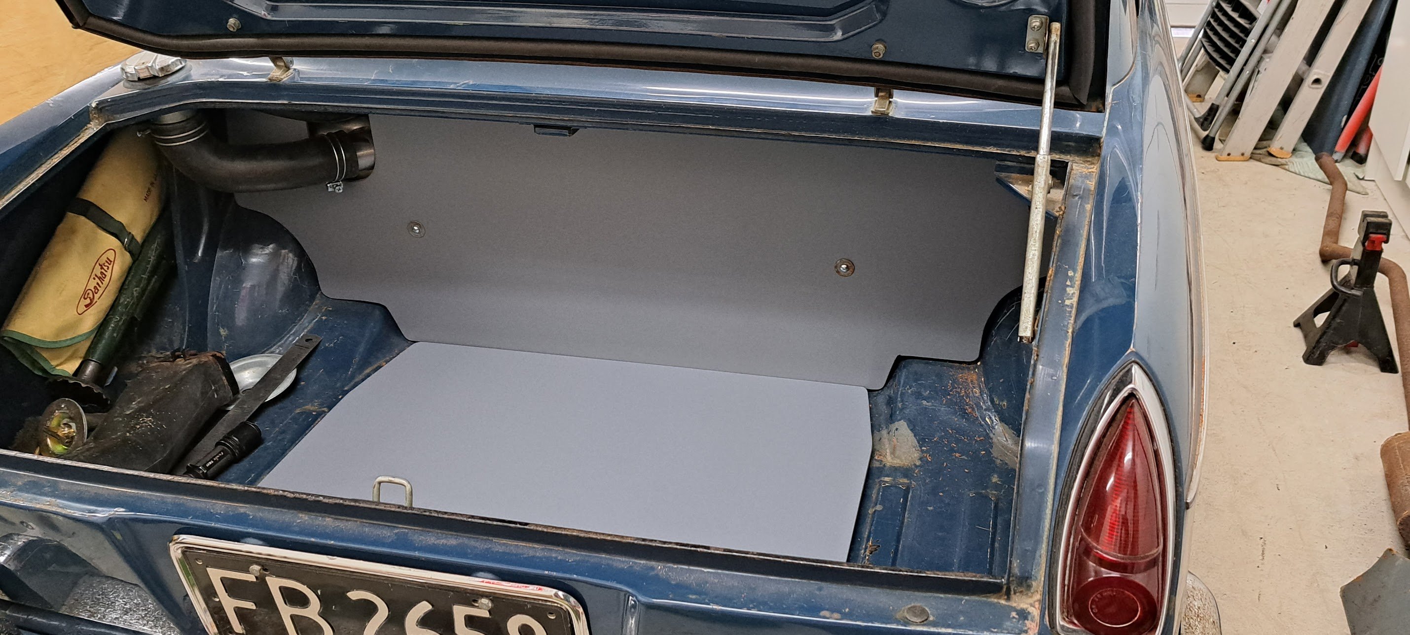
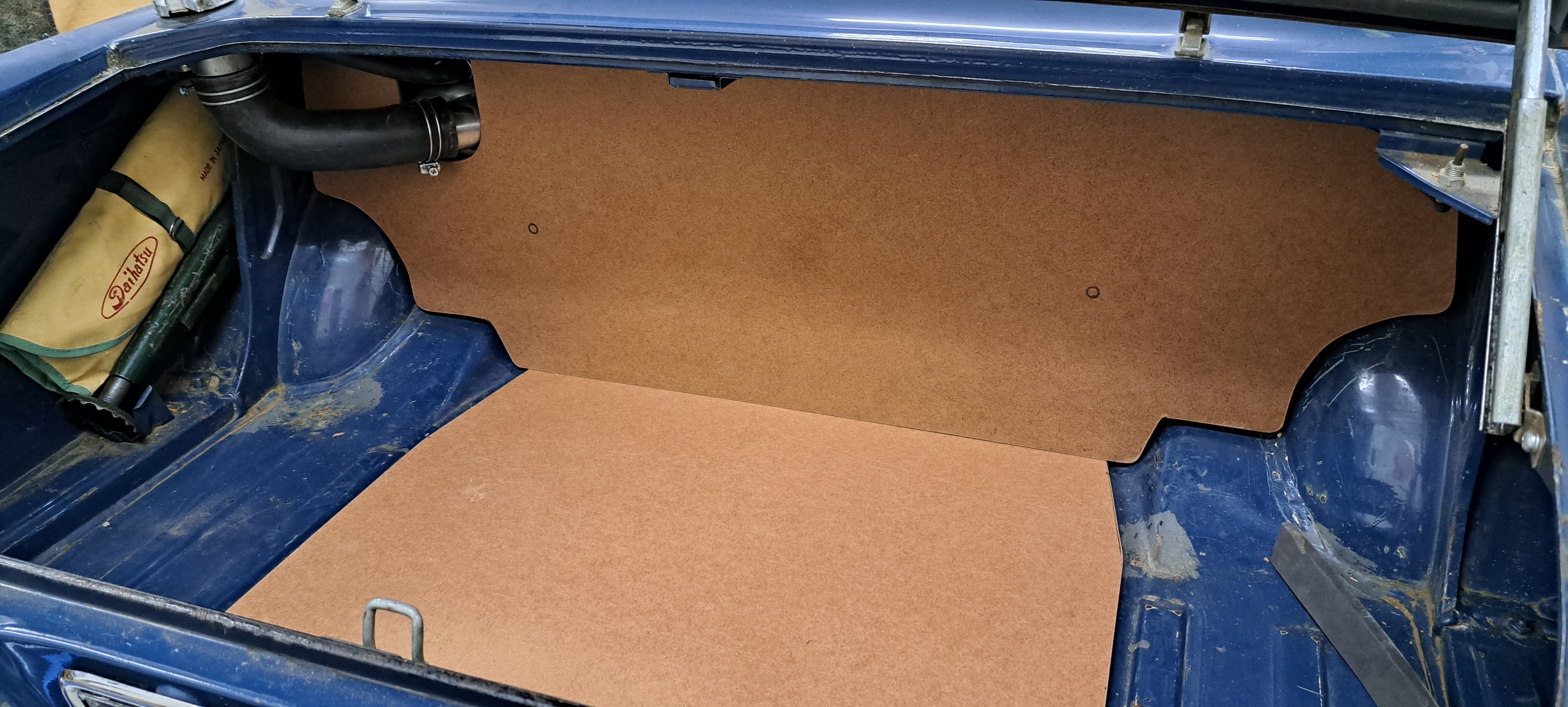
Was out in the shed again today so had a quick measure up and fed the cnc some mdf Quite happy with how much nicer the boot looks with the spare covered, motivates me a bit more to suss some carpet etc. From factory there were a few more trim panels in the boot, hopefully have a set on the way to copy, its something i've never seen before so looking forward to it!
3 points
-
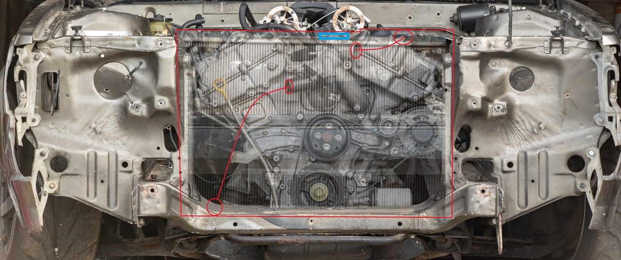
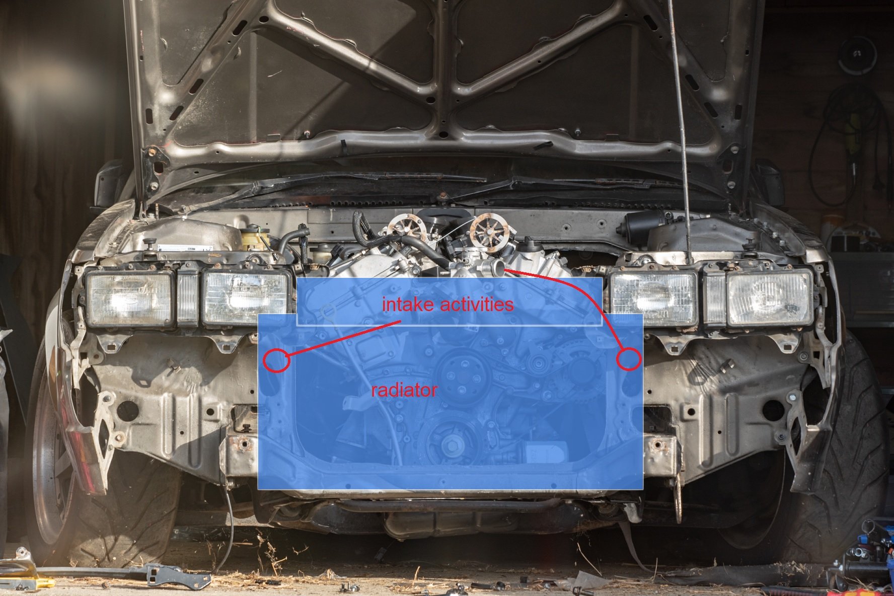
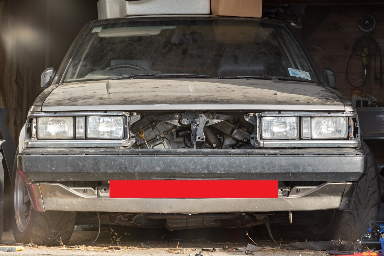
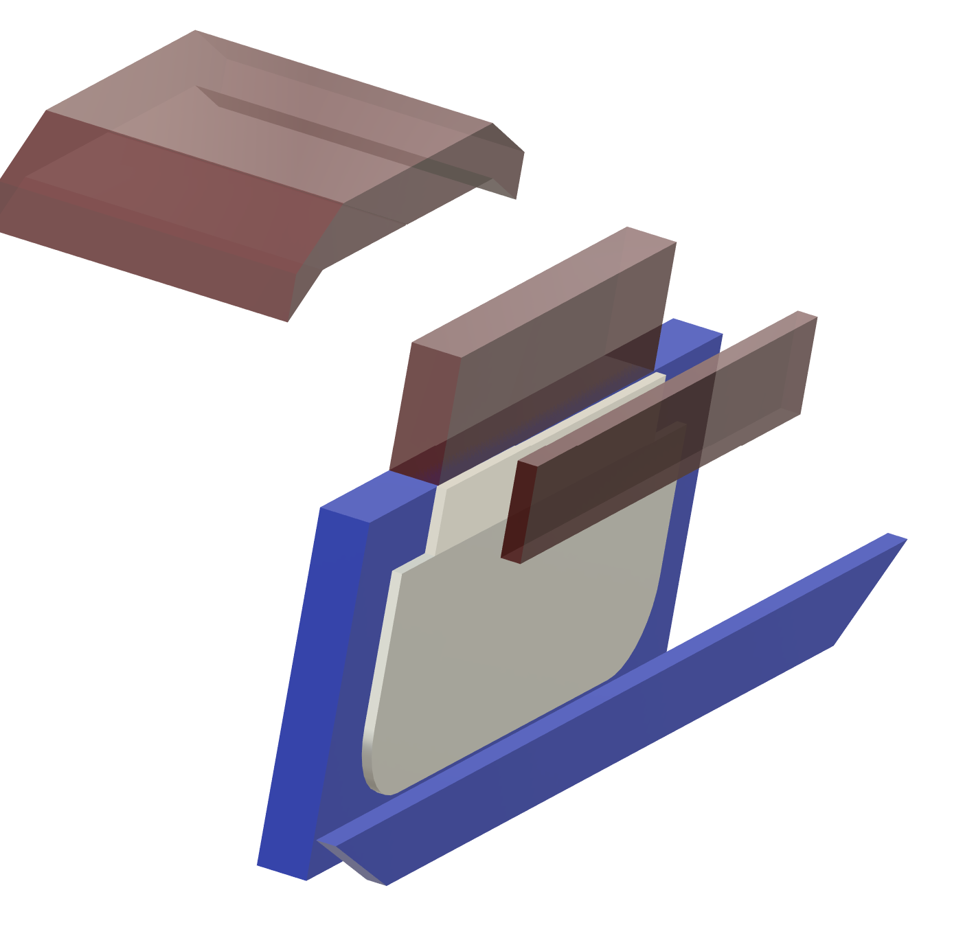
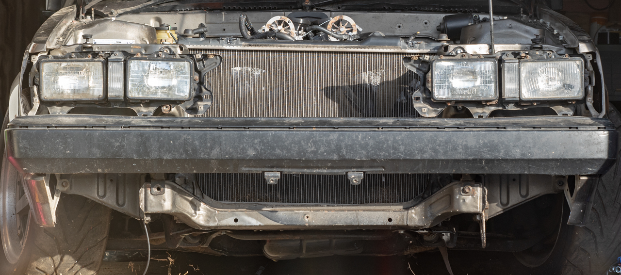
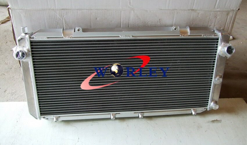
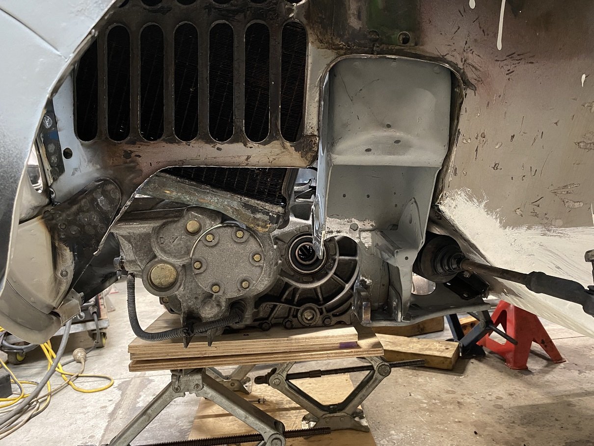
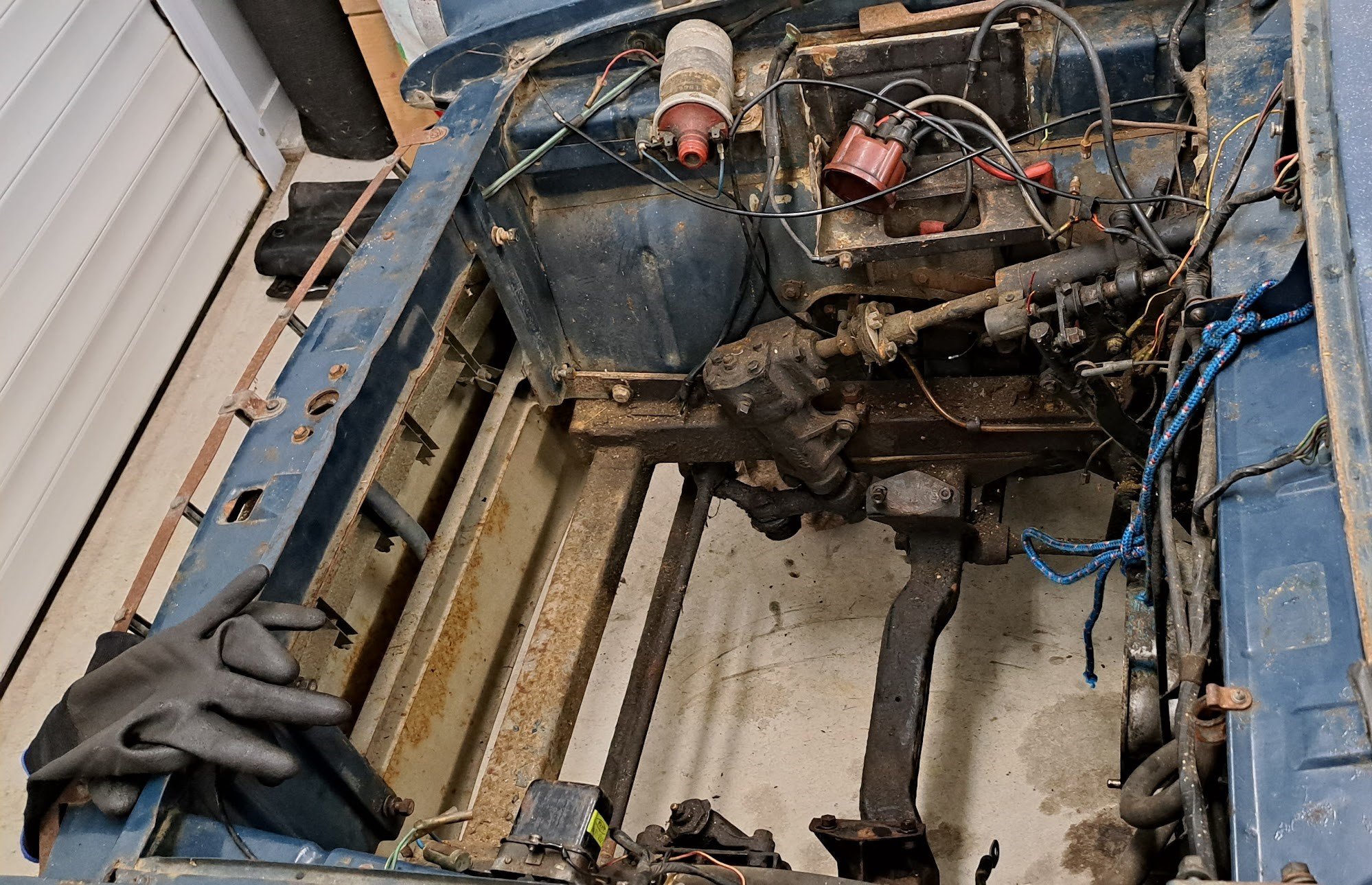
Radiator situation I've got the Mark X radiator in there currently, and although it made everything nice in a lot of ways in the back of my brain I know it's just not going to work quite right. As the top pipe sits too high. You can see it sits a little higher than the top crossmember too, and this isnt on any mounts yet. Just sitting hard against the bottom. The motor's radiator cap (in blue) sits a little lower than the radiator, and the top hose to the radiator flows uphill towards the radiator. All bad news for ever trying to bleed the air out of this thing. Another issue is that I'd love to have a front facing intake airbox that goes through to the front grill, like a lot of the BTCC type cars have. The best option I've found for a low, wide, twin core radiator that doesnt have a radiator cap (and does have an air bleed) is from an SW20 MR2. Being so much shorter, I can dedicate all of the front grill area for the intake. And they're a common upgrade item for MR2s, so cheap and plentiful. The radiator is 5mm wider than my chassis rails, but the end tanks are alloy and on the sides. So will just need a little slice and reweld to fit at the bottom. If I dedicate the top grill to doort noises, then I dont have a huge amount of frontal area for the radiator coming in from just underneath the bumper. Possibly need to remove the bonnet catch as well, but I'd prefer to keep it over having bonnet pins or whatever. This is a rough approximation of how much space I've got for each thing Red is intake stuff, blue radiator stuff, white is the open area that the radiator can get air through. So a lot of the radiator area will be fairly useless if hard mounted against the front of the car, as it wont get any air flow. so I'll try mount it as far back as I can towards the engine. All of this stuff is a bit off topic to my path towards getting the engine fired up, but I've been working on that too. Last night cut the fuel rails a bit shorter, so there's more room at the back. for the fuel dampers without hitting the body. Then also had the underside of the rails milled down so the throttle linkages dont hit the rail anymore. So that's just about all finished once I've retapped the ends and remade the AN lines to suit.
3 points
-
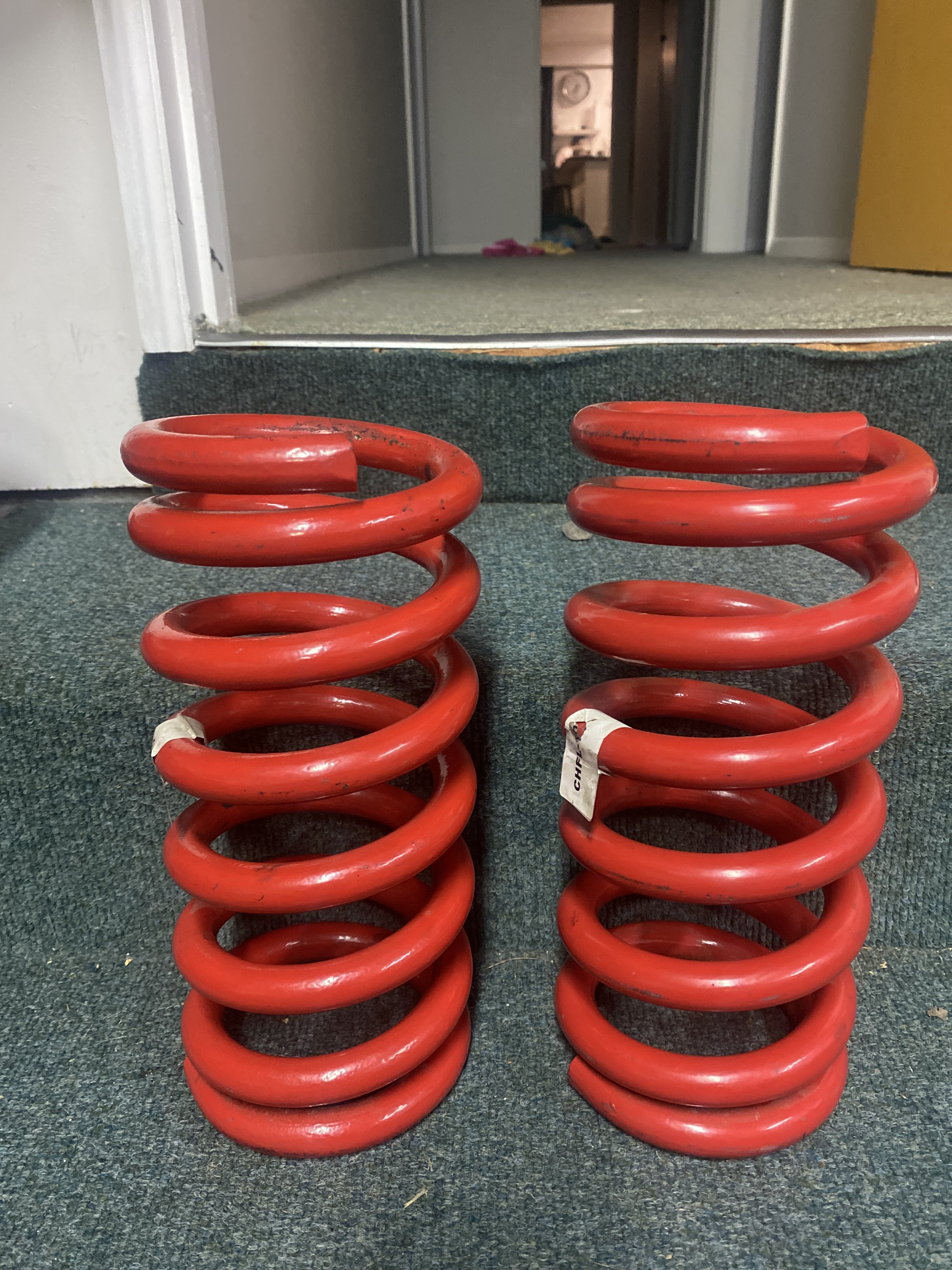
I’m stumped. so I’ve sorted all the dust boots, reassembled to what I thought would be exactly the same set up. But no the passenger side assemble sits lower than the drivers side. (I finger space vs 2). pulled apart again as I read potentially have left and right spring around wrong way…pulled springs and shocks out but I’m dammed if I can tell ‘em apart. springs are HQ 6cyl with identical markings. Spring perch is the same. Would camber spaces/shims have anything to do with it? now that I’ve looked at the dam things so long I can’t remember which one was in the left or right.
2 points
-
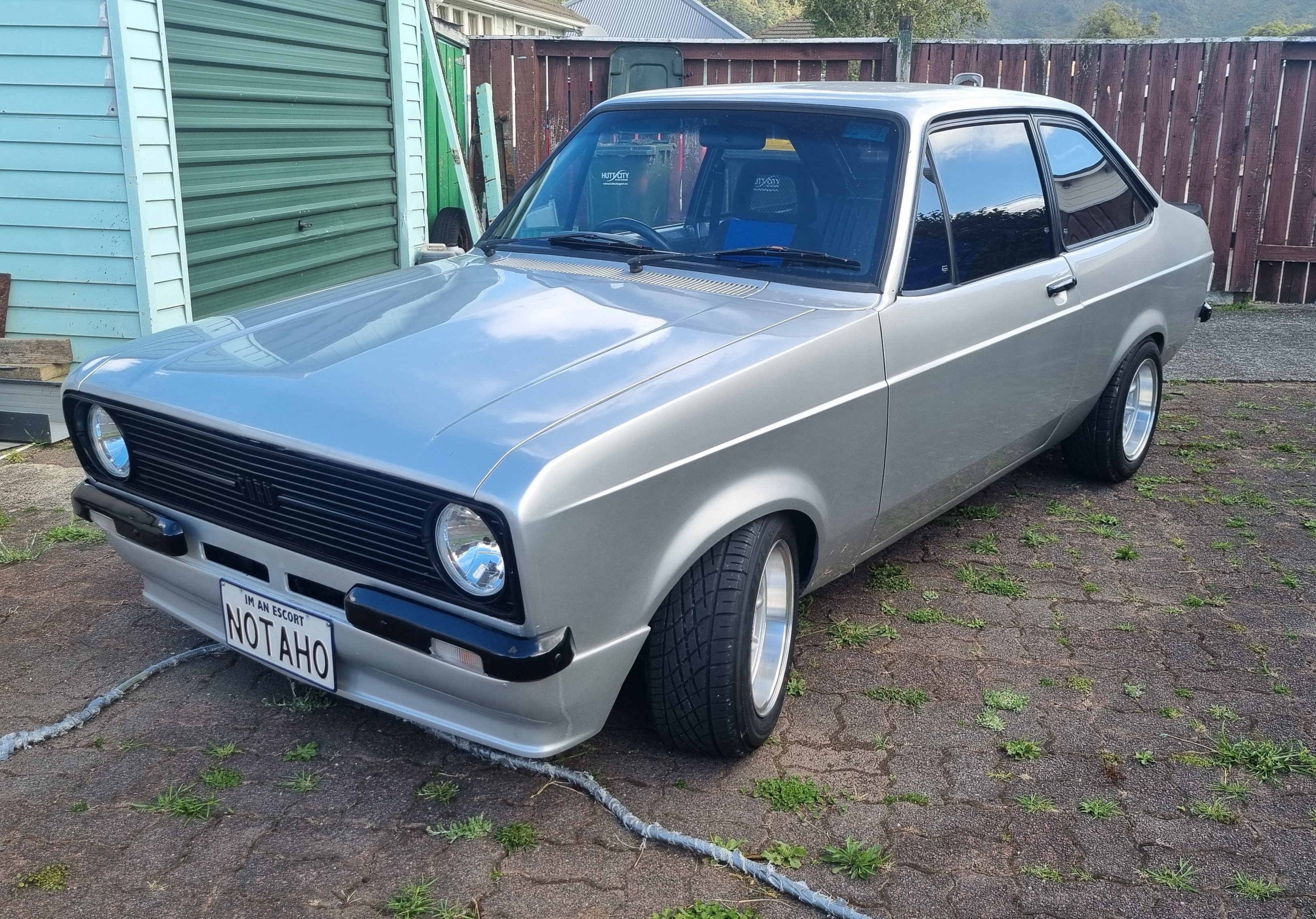
All legal beagle, any cruises etc hmu,will head upto cars in coffee, few things to do still but that's any car really, needs gearbox badly and decide on a new engine, time to give her a beating
2 points
-
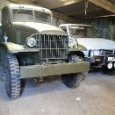
Watched Patton last night, keen for some more tanks.2 points
-
Would I use a full size broom or a 1/35th scale one ?2 points
-
It looks like they are asking you to check if the play is within manufacturer specs Ie they don't want to make a decision themselves2 points
-
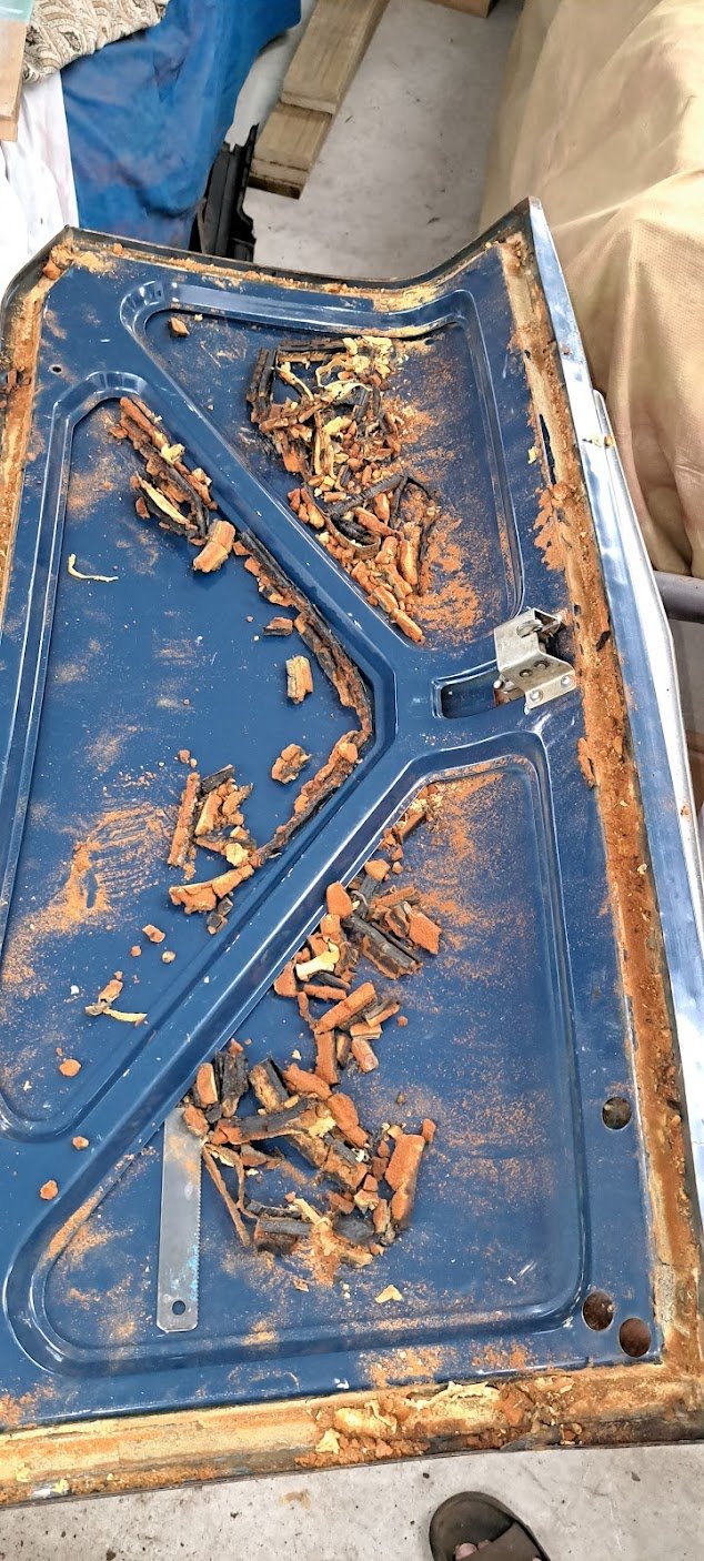
It takes a special kind of idiot to take a perfectly good, freshly panelled car, and chop it to bits. boy I need help Cut all the things!!!!!
2 points
-
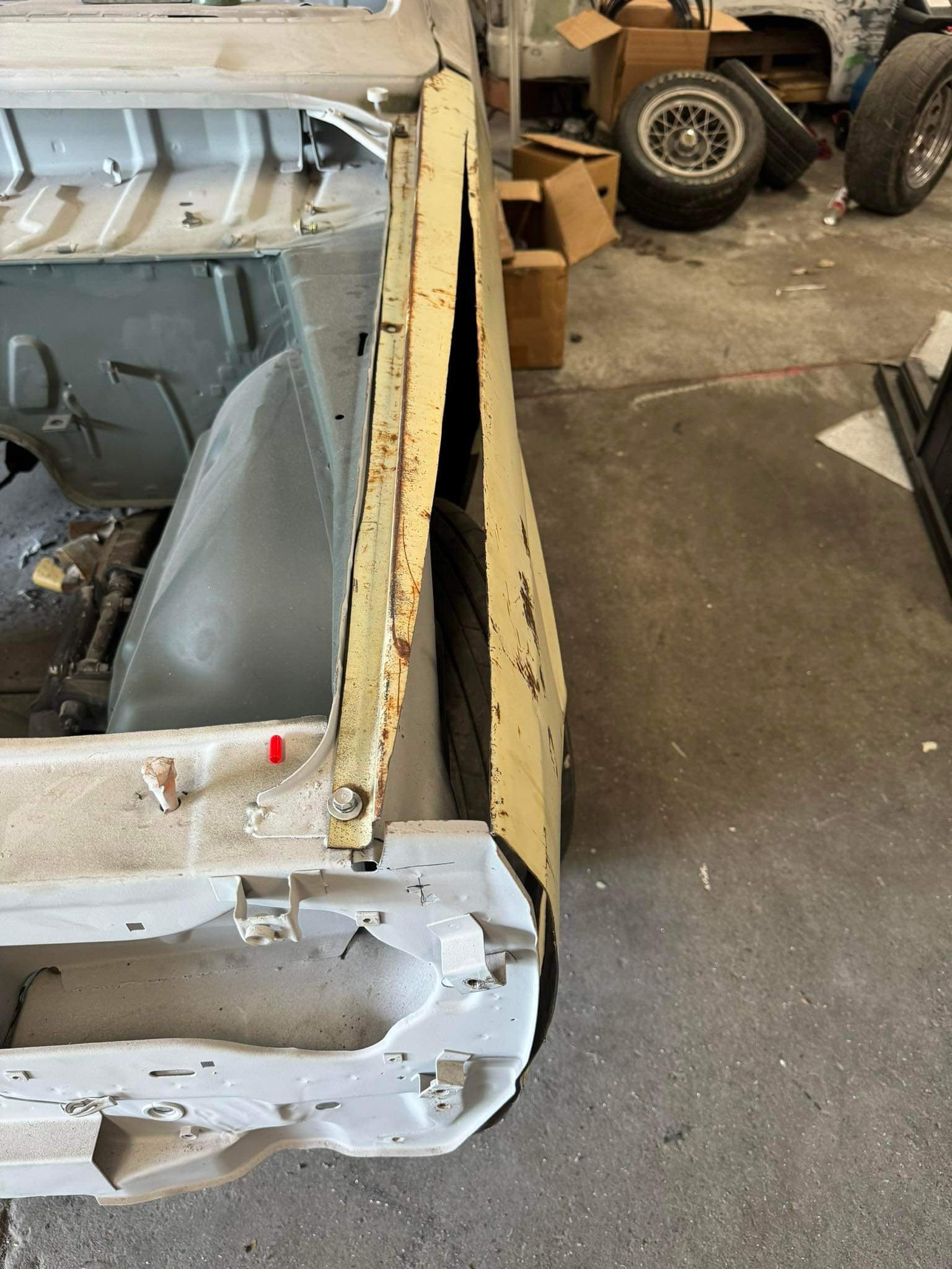
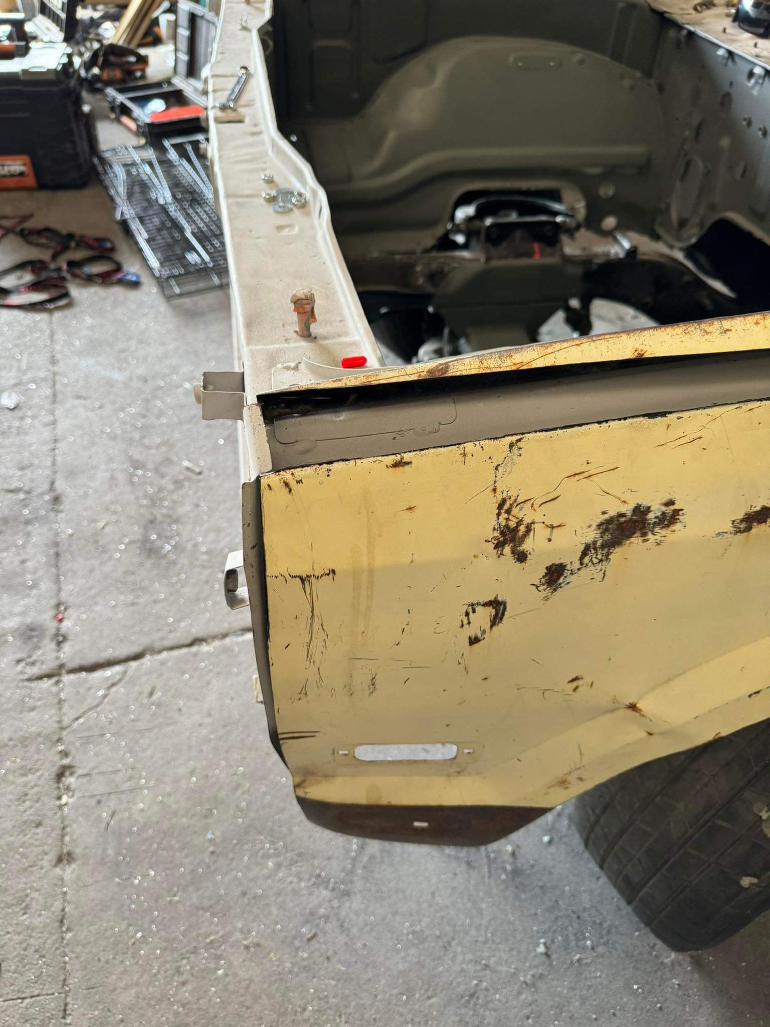
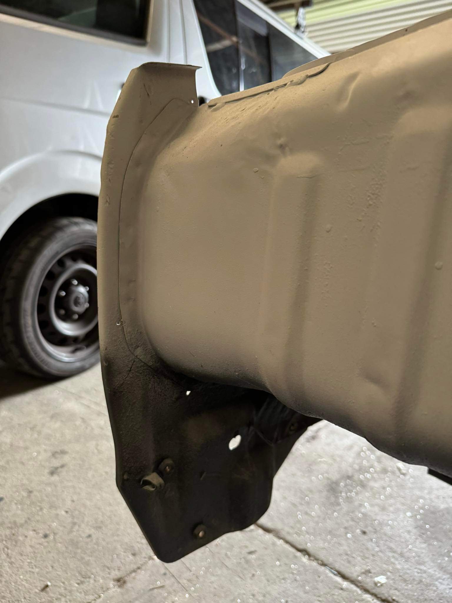
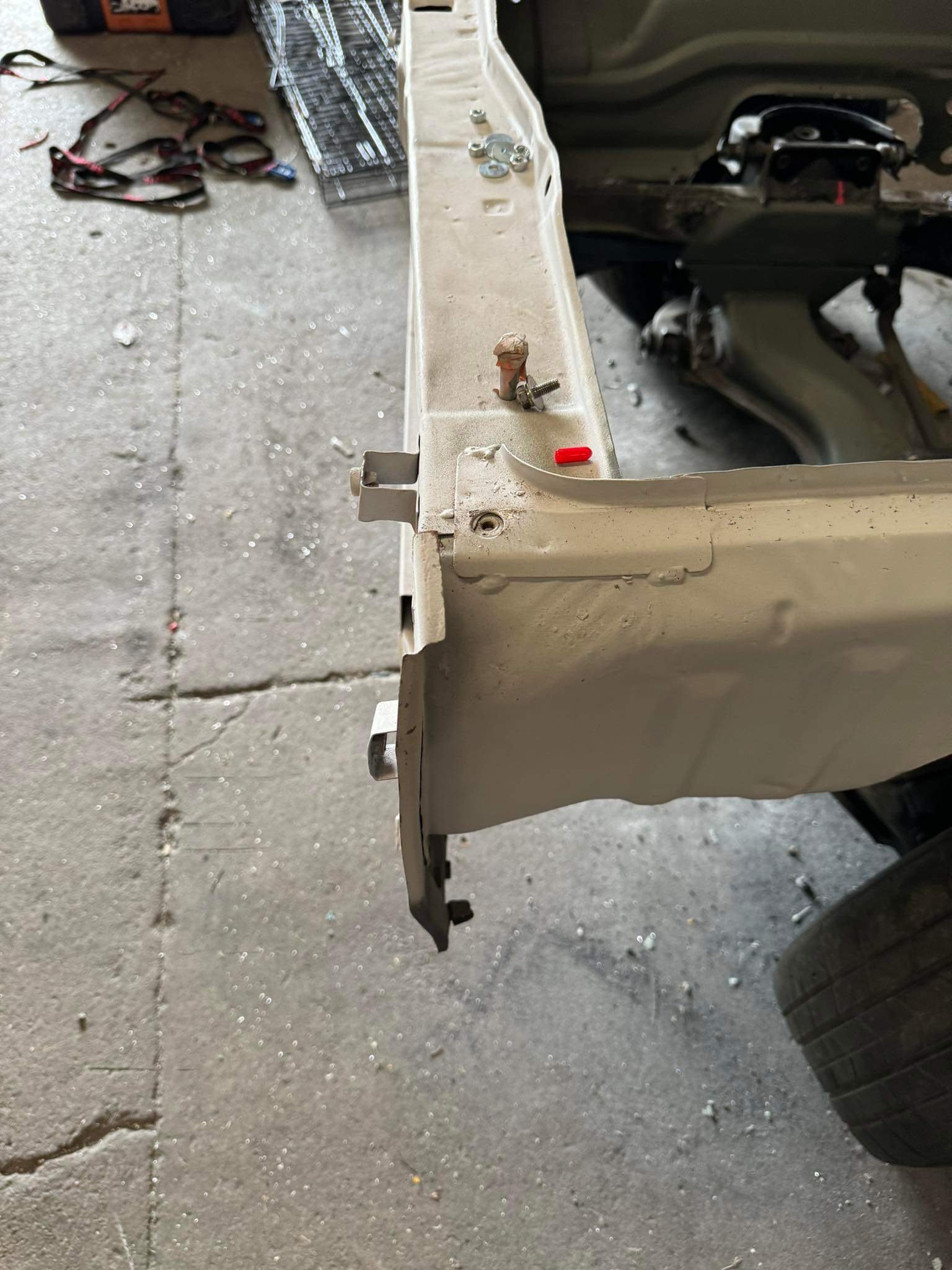
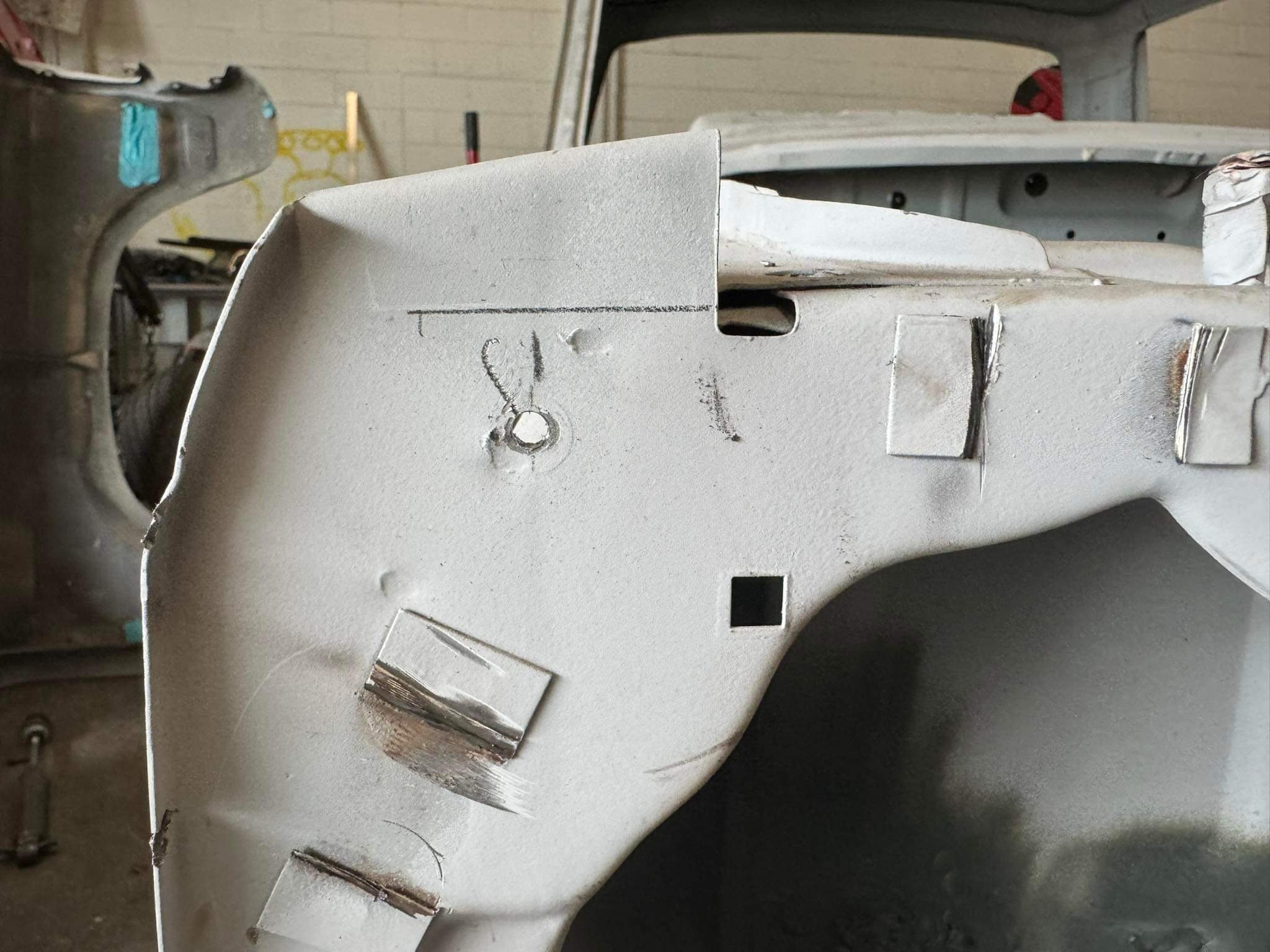
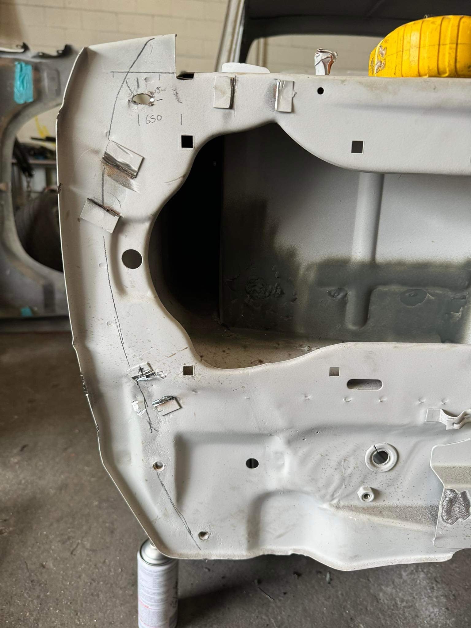
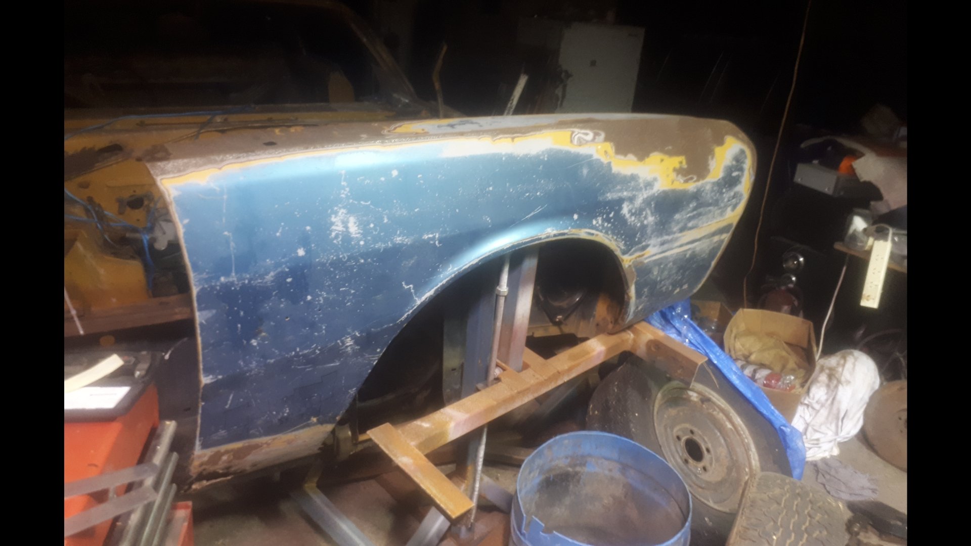
Im still thinking about this once in a while. Tracked down a less fucked right front guard. It was up welles ways. @Goat kindly let me use his house as a freight forward depot. The seller dropped it off, and a mate who was passing by collected it the next day. Picked it up tonight. Defo needs a wee bit of work. But i can buy the inner and outer bottoms off the shelf from Automotive Panel Craft in Oz. Thanks to @Classicdat for lugging it south for me too!
2 points
-
I modelled and printed some door card clips which as always gives me the deepest pleasure. These worked pretty well after some tweaks. These are not exact copies and are designed so they are easier to print, but functionally they are sweet. The drivers side window winder mech was deeply wrong, the wire tension adjustment was maxed out, hacked and the maxed out again, but the wire was still as loose as fuck and while it kindof worked it made horrible grindy noises. This came from the barrel where the wire was straddling grooves cos it was so loose. It was all down in a difficult to reach place, and those mechanisms are notoriously cunty to pull out and put back. Amazing that I got a bollock into that shot as well. The passenger side was sweet and the wire connection looks like this; After a bit of thought and dicking around trying to take slack out of the wire a genius idea came to me; I routed the wire like that through both lift points, which took up enough slack that I could tension the mech properly. Another 1/4 hr of contortion with a torch, phone and screwdriver and I had the wire slipped back into its rightful track. It works perfectly again, yay!2 points
-
Have you got the rubber/plastic bits on top of the springs inside the crossmember? Mayne you have them both on 1 side or 1 missing1 point
-
@30DegreesRetarded did you buy the springs new? They often need 500kms or so to settle . also the longer one will go on the driver's side . Because most cars get driven with only a driver so the perch the drivers side a wee bit higher to stop it sagging immediately trim thr bumpstops if there is enough travel in the shock only. Otherwise your shock will become the bumpstop and that's not good lol.1 point
-
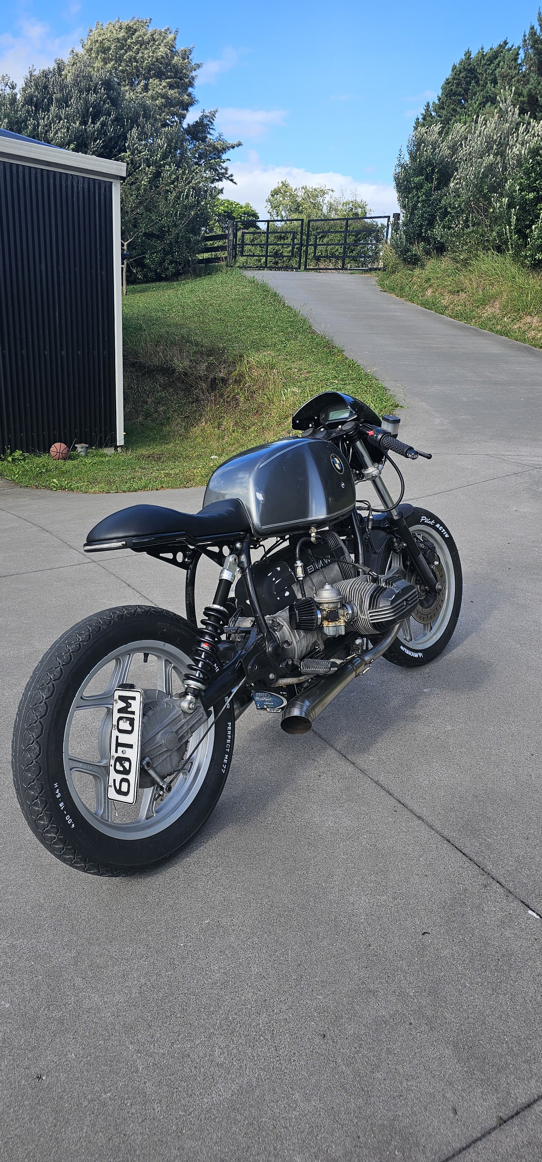
A friend in the UK was given an 1800 engine from a fire damaged bike. He's not properly looked at it (because he's always starting new projects and never finishes anything.. He should be on os ) but he reckons the camshafts could be run in reverse and by changing the chain tensioner location the engine could be changed to clockwise rotation. I have not really looked into those engines because it's hard enough finding a 1500 and an 1800 engine would be moonbeams from a wrecker. But they are lighter and have fuel infection already fitted.1 point
-
Apologies for being slightly off on a tangent, but man, does this bring back childhood memories:1 point
-
Come on now, start with a full size one and whittle it down...1 point
-
1 point
-
Axle shortening or joining, if it's just an axle, should be fine if it's done well and with a suitable weld process etc, take notes of what you do, what filler rods etc The exception to this is jag rear ends, this is because the driveshaft is the top suspension arm. These need a more specialized process because a failure would likely be way more badderer Battery- if your fuel system is modified then the CCM requirements apply, so battery has to be isolated from fuel in a non conductive box. I have had a customer with a stainless battery box who didn't want to change it, line the inside of the box with rubber sheet so it was no longer conductive between the battery and everything else1 point
-
im keen to see what you do here re half shafts, its the bane of fwd engine/gearbox swaps unless you have a lego parts bin. I seem to recall something about a splice to be welded but was ages ago i looked and outside my skill level/found some lego instead. You can also employ this when you put the sr20ve 20v with sr16ve gearbox in your k11 if nissan lego doesnt work1 point
-
My engineer (who might be your one too if initials are JC) said there were no real guidelines on it and I offered to have them fully welded by an engineering shop which he knows and was happy with that. So might be worth tacking it and having an engineer shop weld it up and provide a receipt stating exactly what they did.1 point
-
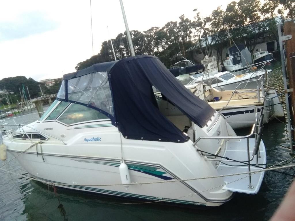
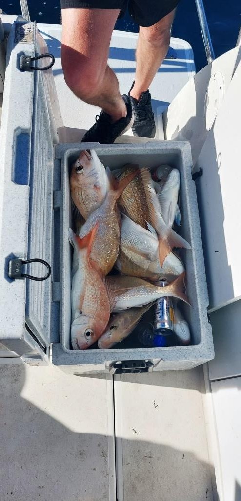
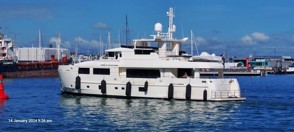
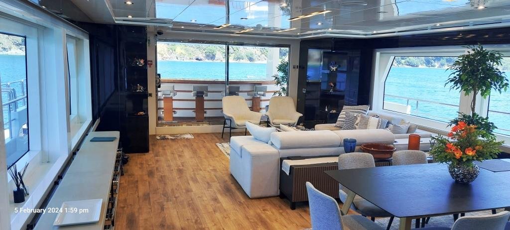
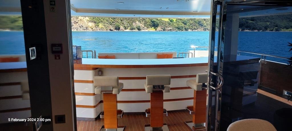
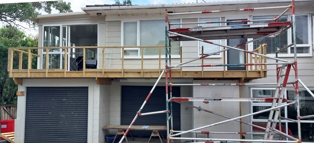
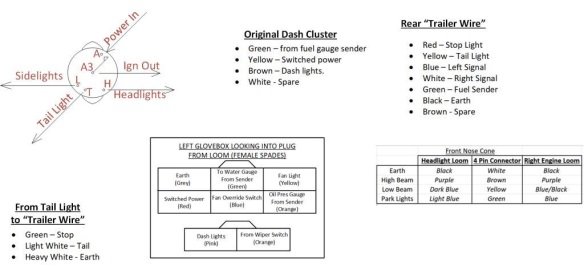
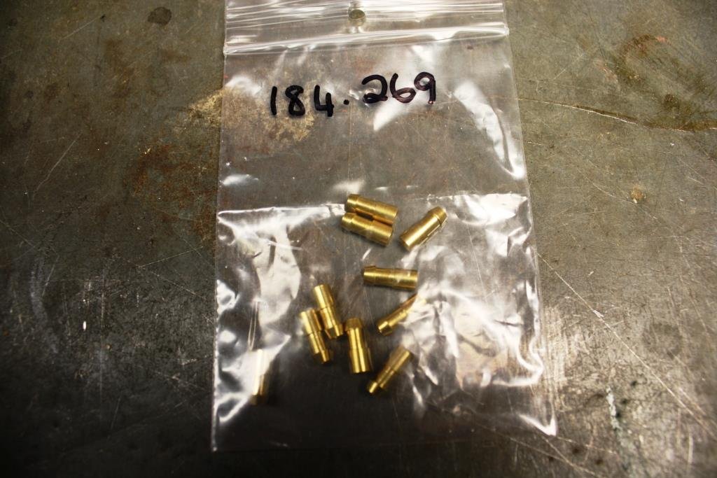
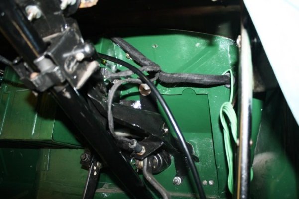
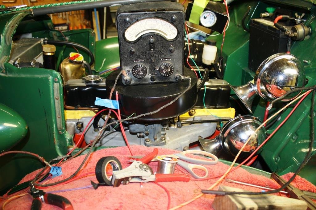
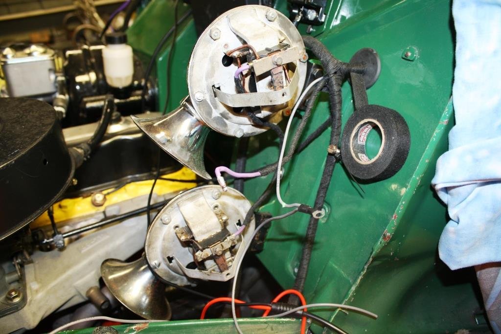
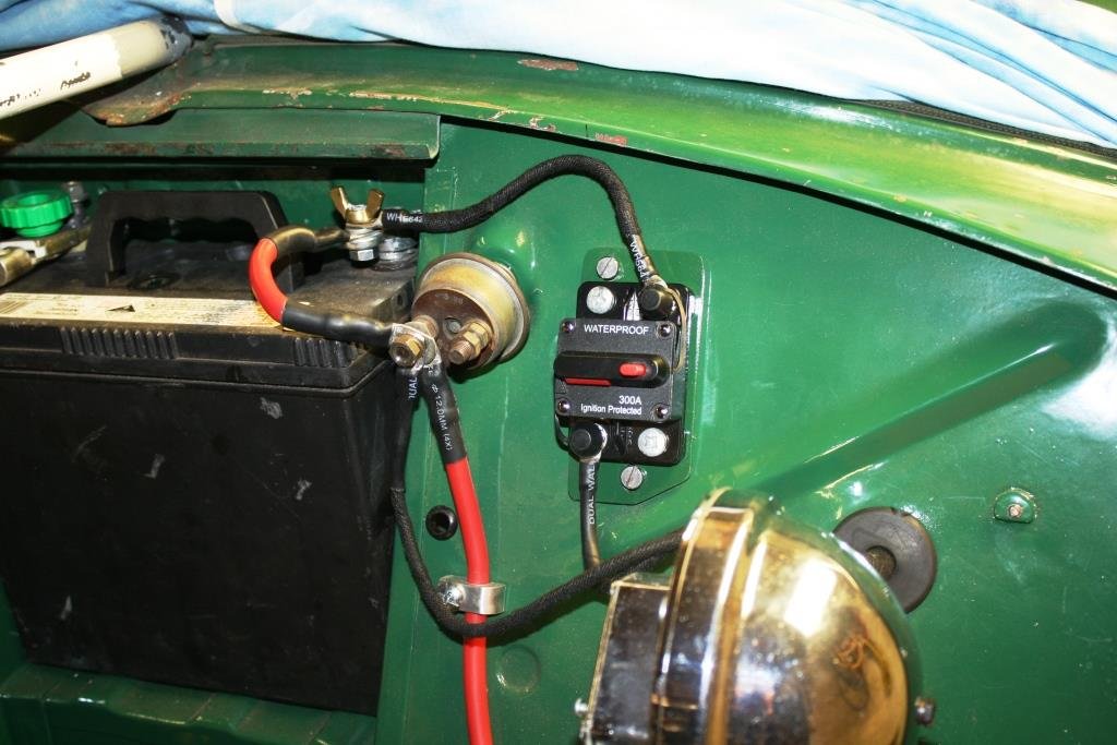
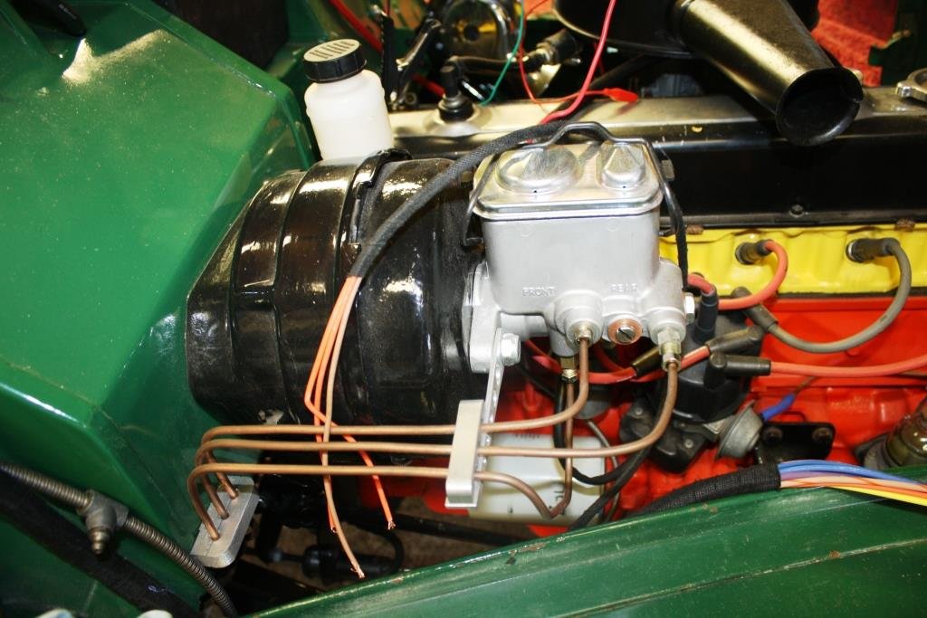
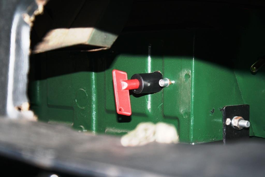
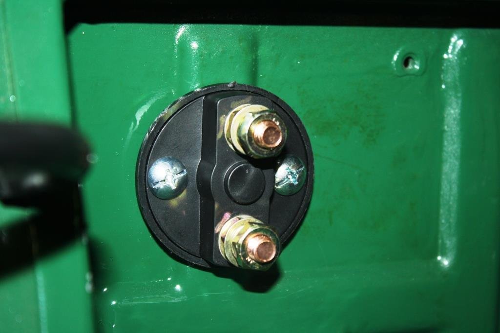
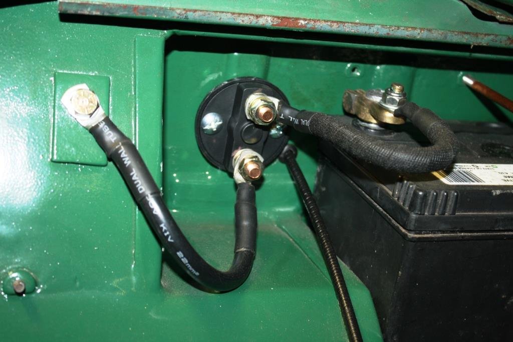
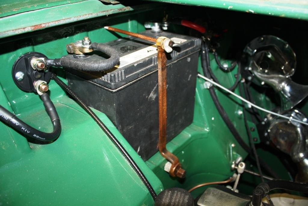
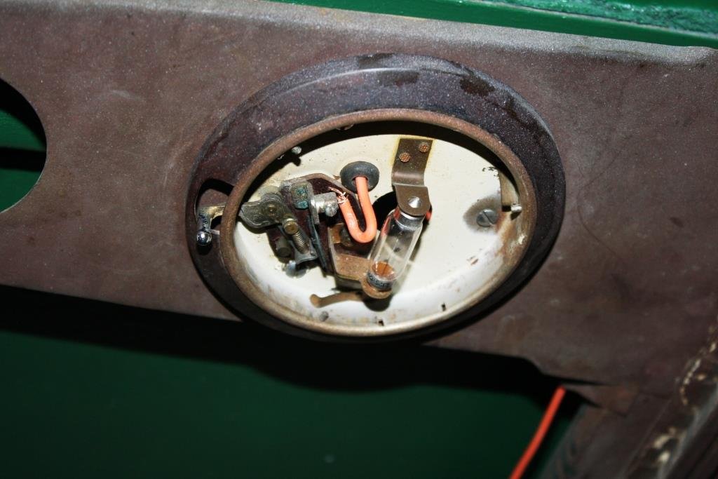
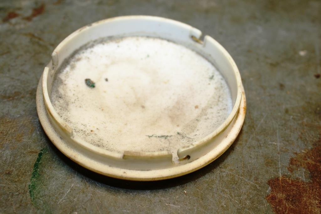
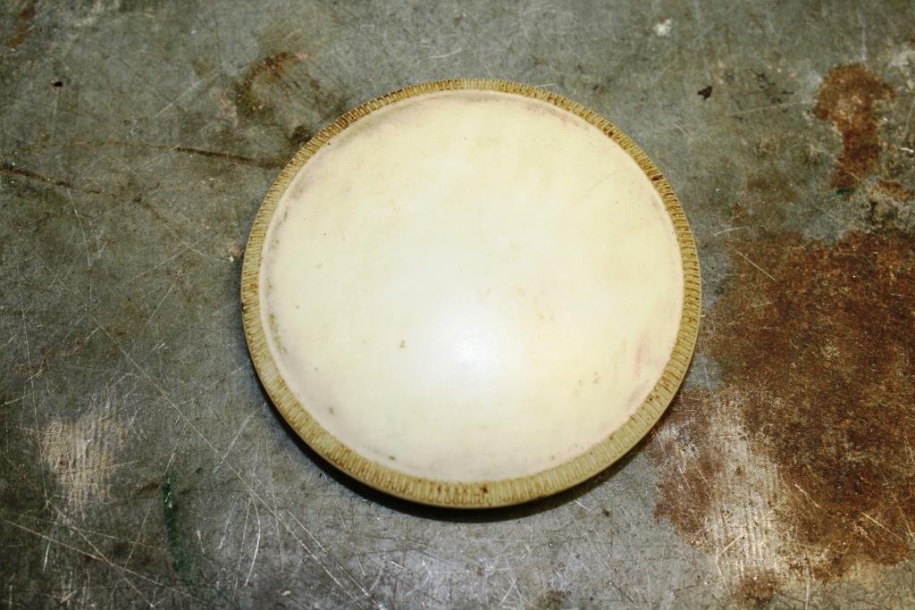
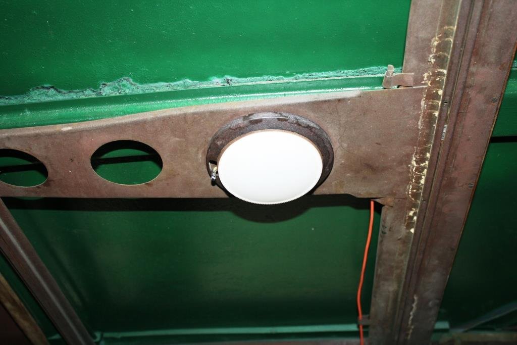
…………Yes I know I’ve been a slack prick, re: this thread. With final arrival of summer the good ship Aquaholic insisted that I take her and some of my disreputable mates out fishing… (What could possibly go wrong?). It was a hot day, we got thirsty, we drank heavily and we “got fush”…….(as you do). A few days later my brother turned up at the Viaduct in this bloody monstrosity, and the good ship Aquaholic (and a certain part of my anatomy) felt very, very, …. small…….(Sibling rivalry can get complicated!). ….so we headed north. The view from the bridge was cool…… Accommodation wasn’t too shabby…. …. And the lounge was bigger than the one at home… Thankfully there was a bar on board for self medication! Back home I was stricken with a bout of the much feared “home handyman-itis” and I accidentally started rebuilding the front of the house… (Note the cunning accumulation of Brownie points with the “ever lovely Mrs. sr2”). After the above brief hiatus I’m finally back to Rigamortice’s wiring. I’m trying to document as much as I can because my memory is like a sieve. I managed to source some cool old fashioned bullet connectors…. I’m almost finished under the dashboard, getting sick of working upside down. The dip switch still works so I hit it with some contact cleaner and we’ll see how it lasts. I’m running relays on the lights so it won’t be carrying the amps that it used to. I’m using my 70 year old meter just because I can. The horns are all wired up but they sound like two strangled cats, I’ll have to do some research on how to tune them. Circuit breaker in place instead of a fusible link. Mounted the battery earth cut out through the fire wall Repurposed an old offset ring spanner for a battery clamp. Managed to get some life out of the interior light with a new bulb and fresh wiring. Cleaned a ton of crud of the diffuser…. And it works.
1 point
-
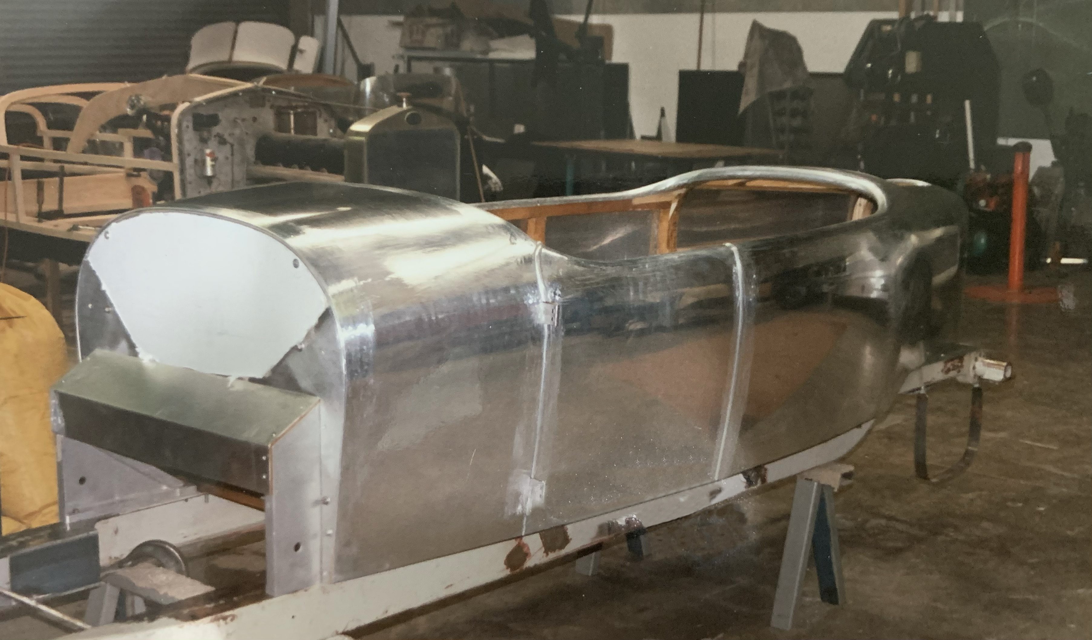
About 4 years ago I purchased a collection of Bugatti parts from the estate of a chap who had bought them in the early 1980s with the intention of building a Type 49 Bugatti tourer. The previous owner disassembled all the mechanical parts (which evidently had come from a variety of donor-sources) and some deterioration subsequently occurred when vital mechanical components were stored in a room where the roof was leaking. The previous owner also had a very smart "Grand Sport" style body-tub fabricated for the project. This is a close copy of the "Compton" bodies fitted to 3 early T49 Bugattis, a reproduction of which was fabricated for the Southward T49 in NZ. I have been cataloging and cleaning up the parts I have, whilst working out what parts I don't have. Also, I have been scouring internet sources and progressively acquiring missing parts, requiring importations from France, Belgium, Germany, The Netherlands, Canada, and USA. Fellow Bugattistes have been very generous and helpful with information, advice, and spare parts. Recently real work has commenced. The chassis has been sand-blasted and set-up on an engineering table, all of its flaws exposed. We have commenced assembly of a Bugatti that never existed, but one that will be constructed from almost exclusively 1920s and 1930s authentic Bugatti parts, and which will conform to Type 49 specifications in all respects. A photo of the body-tub, nearing completion, in the workshop of Black Arts, C1980s? Sent to me by GregChristogoegl, who built the bodies there.
1 point
-
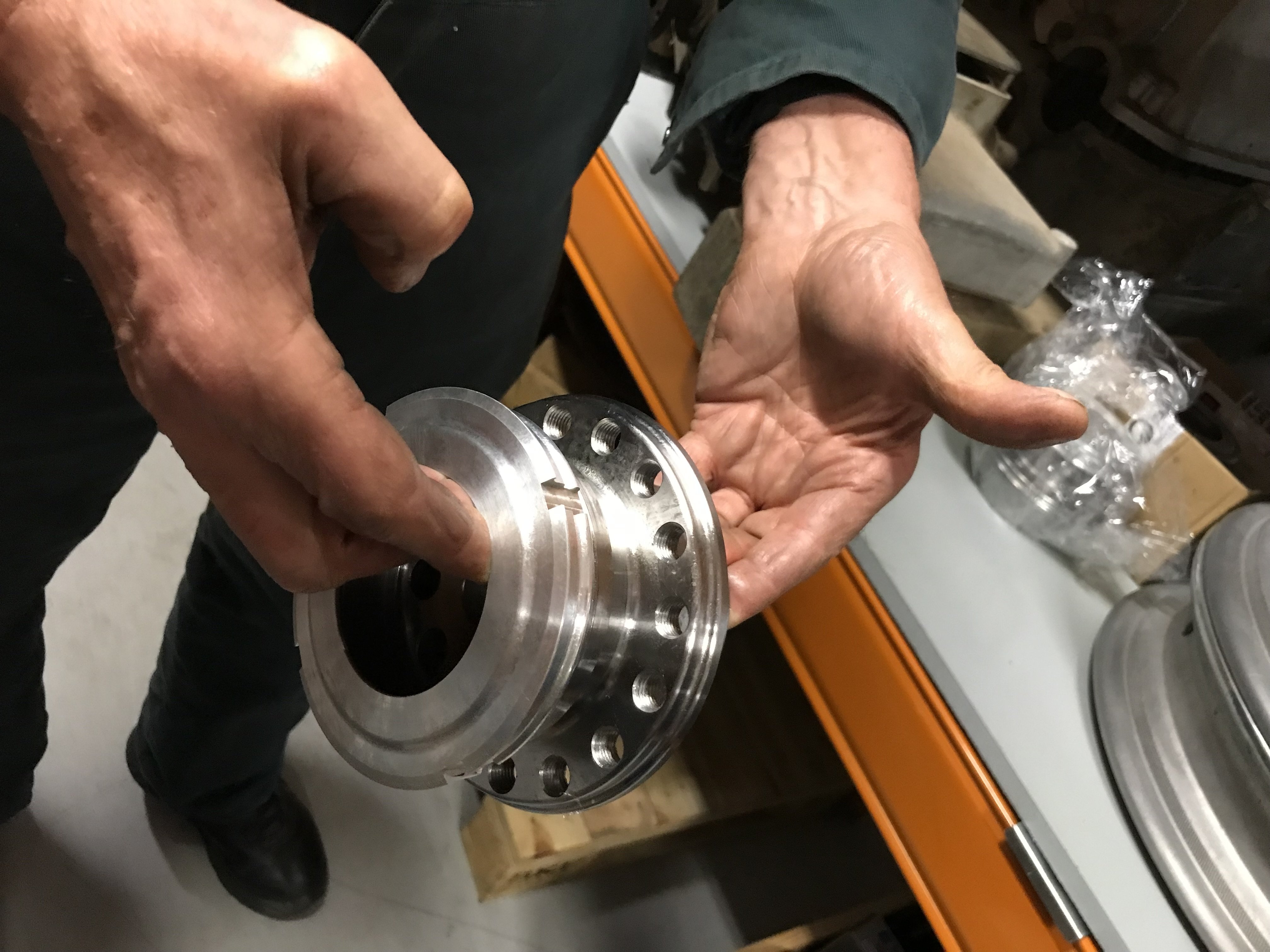
Rear Axle Outer Hubs: To secure the fancy alloy wheels onto the stub-axles on the T49, Bugatti designed a rather complex outer hub. In my pile of bits, I had one of these, but not the other. There's a mob in Geelong South who specialise in doing custom CNC jobs for racing cars and V8 Supercars etc, and so I sent them my existing hub which they measured and copied x 2 - I figured it was best to go with the same on both sides, and keep the original as back-up. Lovely shiny new things!
1 point
-
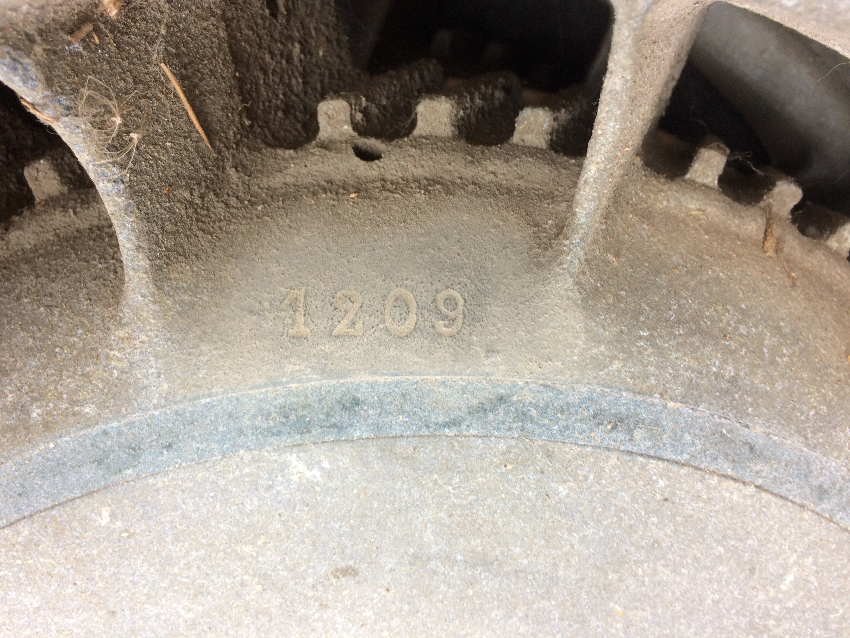
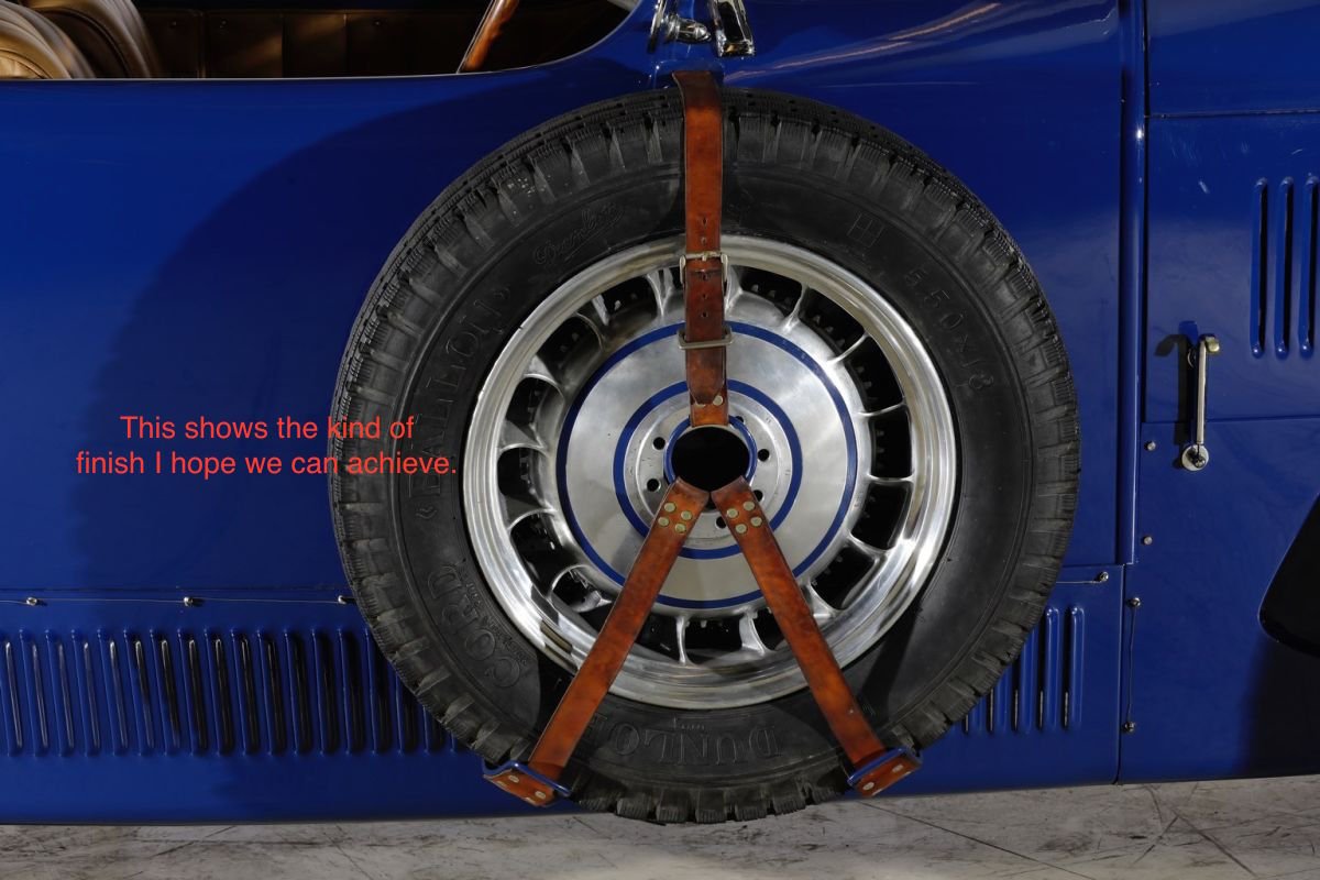
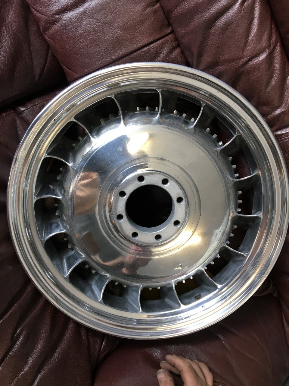
Wheels: Bugatti was one of the first manufacturers the employ in-house-designed alloy wheels, used on the 1924 T35 Racing Cars at their somewhat inauspicious debut at the French Grand Prix, Lyons. Bugatti-designed alloy wheels were subsequently employed for GP racing cars, and for also certain touring models, such as the famous T41 Bugatti "Royale". For the Royale, he designed a 1-piece alloy casting resembling a hydraulic turbine wheel. These wheels, at a slightly reduced scale, were offered as options for purchasers of the T49 touring Bugatti, and my pile of bits included 5 of these T49 alloy turbine wheels. The factory-stamped number is visible, as are traces of original paintwork. A friend has a touring T49, amongst his collection of Bugattis, which he keeps in Europe for motoring around the Continent, UK, and North America. He experienced failure of one of his original alloy-wheels, and so had all his wheels tested, discovering that they were all suffering from advanced fatigue and cracking up. The castings are 90+ years old, so it's not surprising that the metal may have become brittle over that time, especially with use. Luckily he managed to secure a replacement set which were the last remaining examples from a series that was cast a couple of decades ago, and has had no trouble since, although the current whereabouts of the patterns is a bit of a mystery. With this information, I determined to get my set of alloys crack-tested and properly checked. I thought it was probably worth getting the aesthetics attended to at the same time, as all 5 were showing oxidation and pitting that needed reversal. This image shows my instructions to the wheel-polishing mob, with a picture of a "Grand Sport" styled T49 that went to auction in France. Can't say I'm disappointed with the outcome - nice work! This one shows a bit of a curb-side divot, so it will be the Prince Harry. Crack-testing of all wheels came up negative - whew!
1 point
-
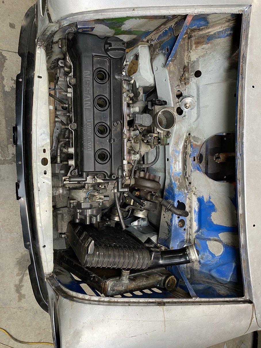
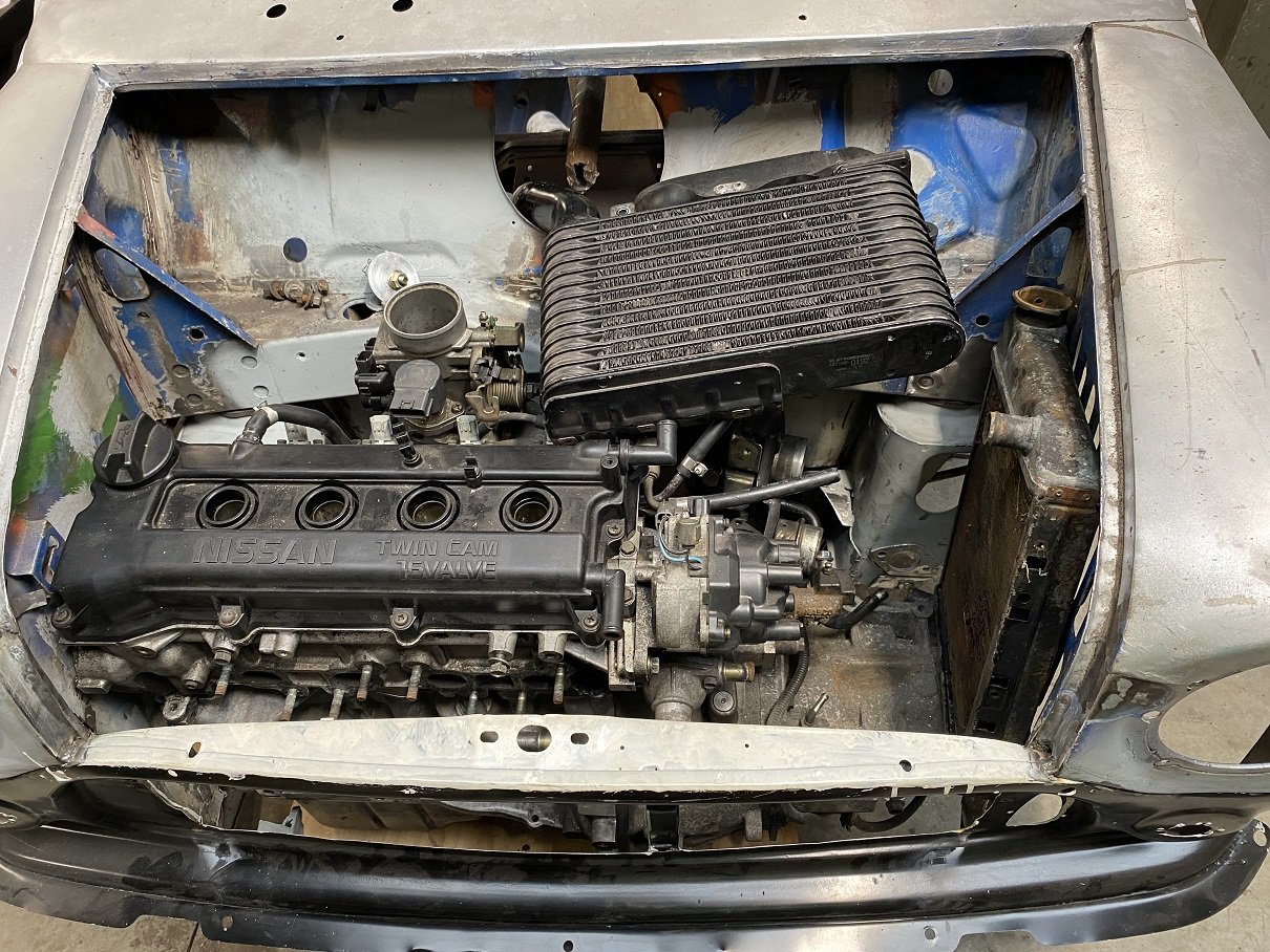
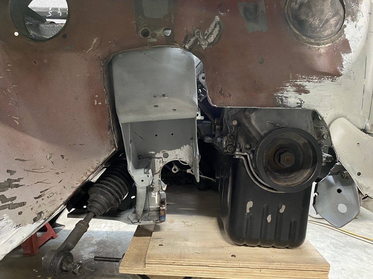
The engine is pretty much in the only place it fits. With more trimming around the back of the subframe I might get another 10mm before the gearbox meets the steering rack. I'm going to step the top/front corner of the inner wing into the guard to get a little more clearance off the corner of the head. I threw some "stunt parts" in the hole to see if there is any chance this is going to work. Mounting the turbo at the front will have almost all of it in front of the grill.... But if I put it over the gearbox... There might be enough room to run the manifold under the engine, then up the back to the turbo then back down for the dump pipe. Loads of room if I top mount the IC.... interwarmer styles. Gonna need a powerful fan and vents... Only done the lower control arm mounts so far. Still got to make a bridge under the top arm mount. I trimmed the inner guards and hammered some new flanges to put some stiffness back in them. Turned out quite good! There will be a CV and driveshaft here to try get an up and down pipe around.
1 point
-
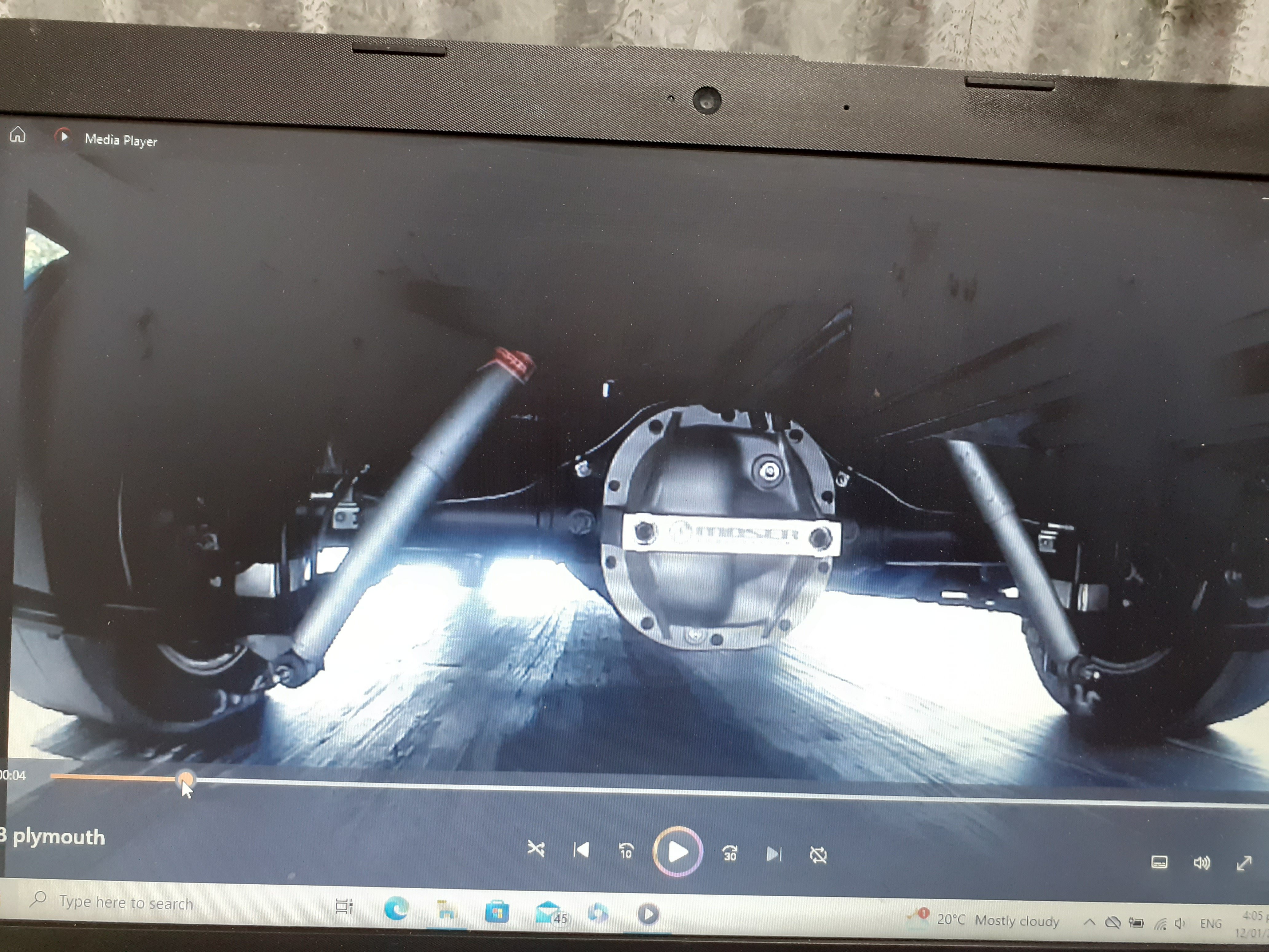
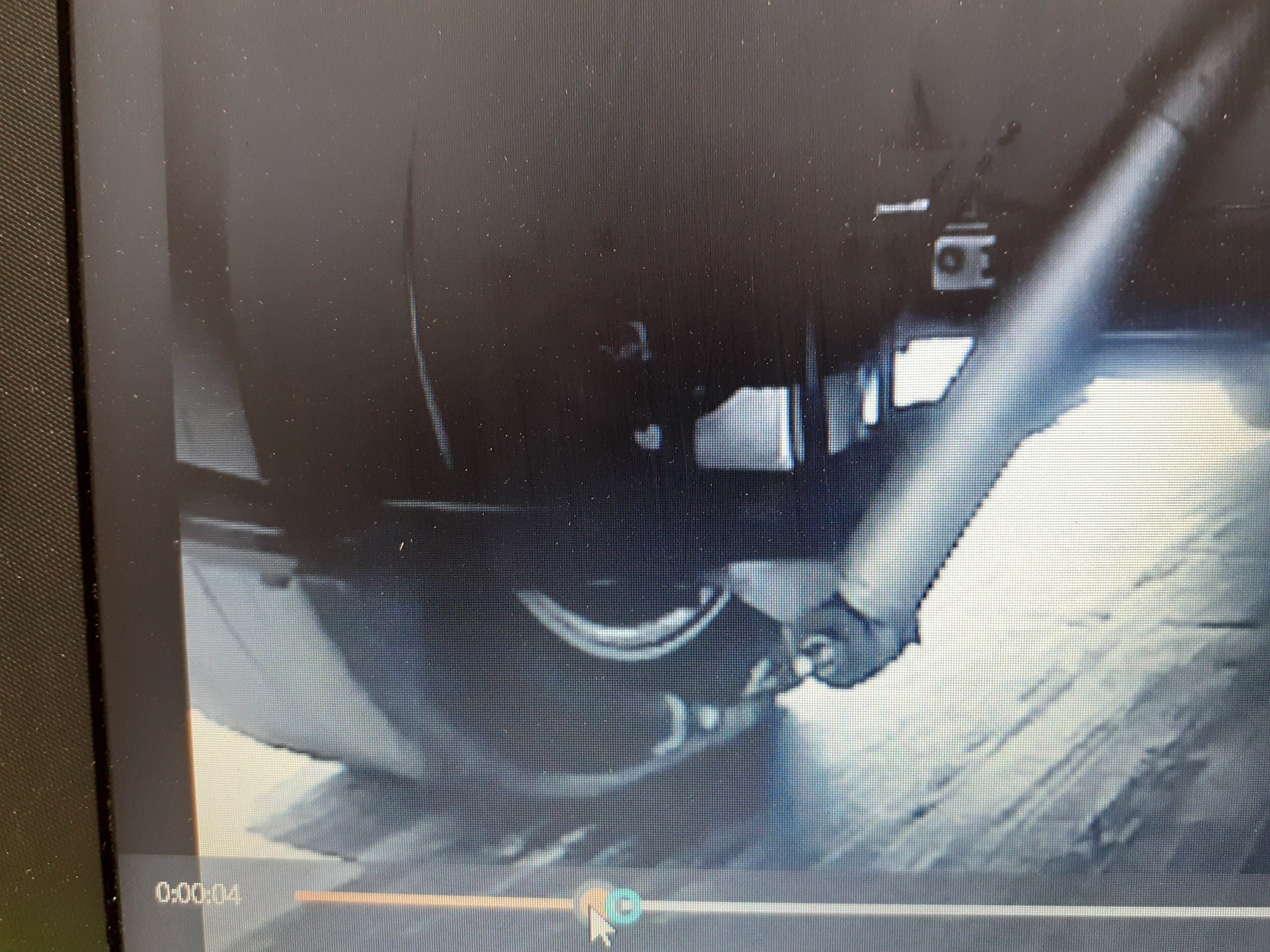
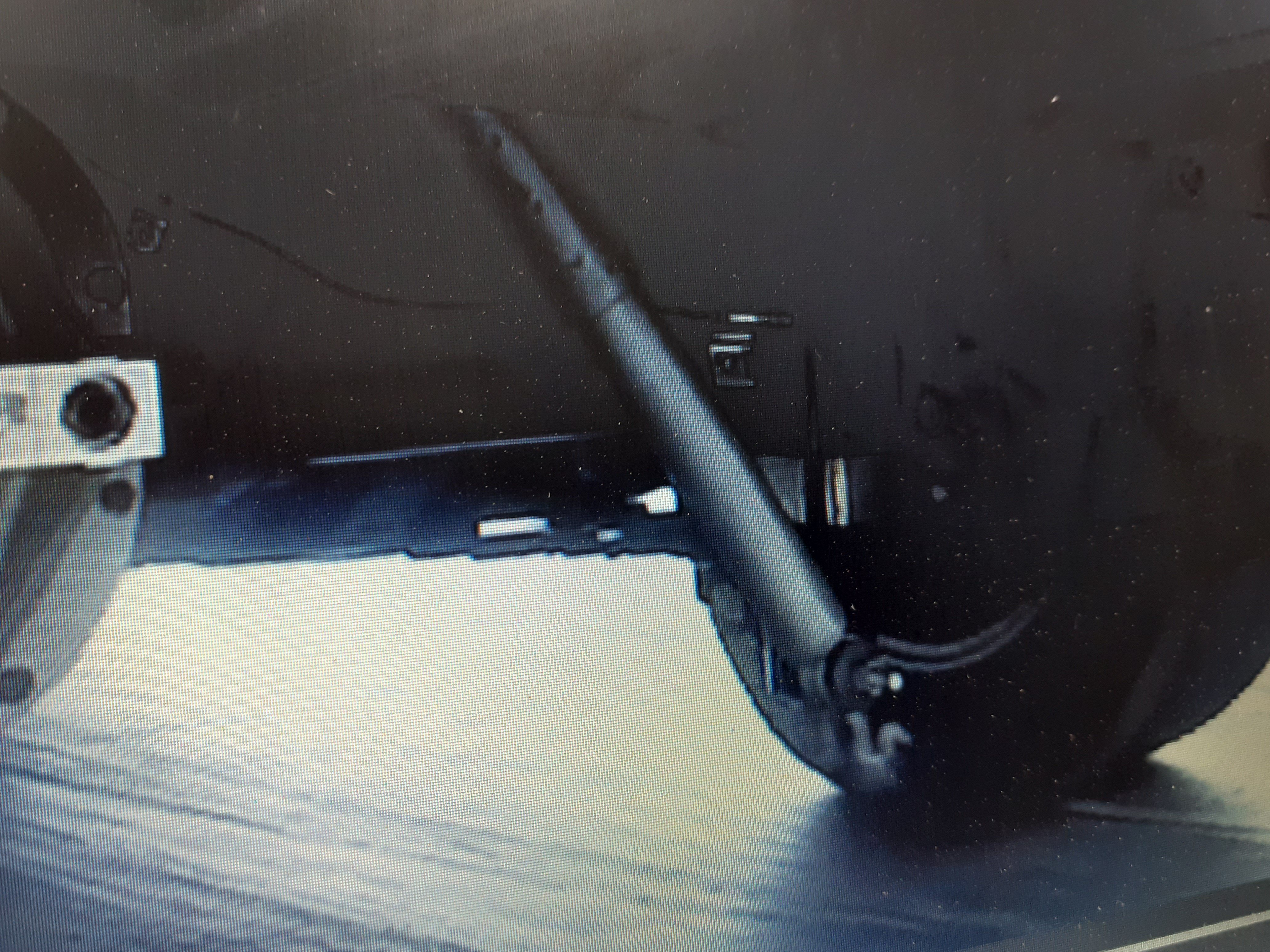
Springs So after a couple of drag meets I'd noticed the right side was sagging a little bit, it was about 15mm lower. I'd always known the rear suspension would need a bit of help and I think the spring has had a bit of a tweak from being shaped like Steven hawkings spine The pinion snubber has been working hard as well, it's actually deformed the body side, and the witness marks show the pinion snubber bump stop has been squashed to the point the bracket has hit the floor. I think this was probably at Hampton downs as where I was doing skids there was a bump that you can hit which unloads the tyres to get it spinning At os drags I'd put a camera under its bum to see what's happening and it was quite interesting The spring gets quite twisted and the left rear tyre gets squashed a lot more than the right side due to the diff wanting to rotate The car always feels quite flat though . The VG used to do the opposite, it would squat considerably on the drivers side Perhaps it's because the fatty driving it is in the right place for ballast haha
1 point
-
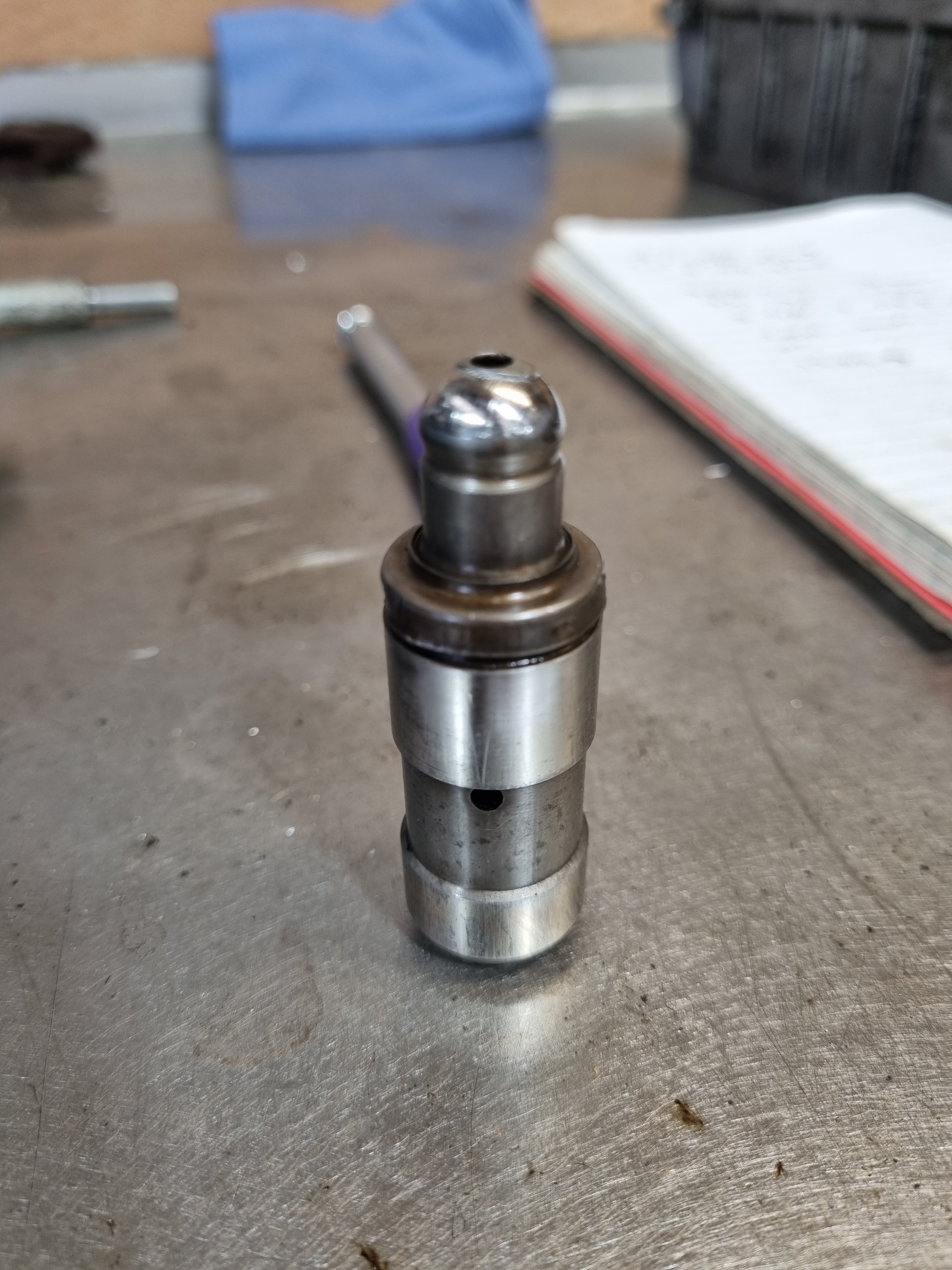
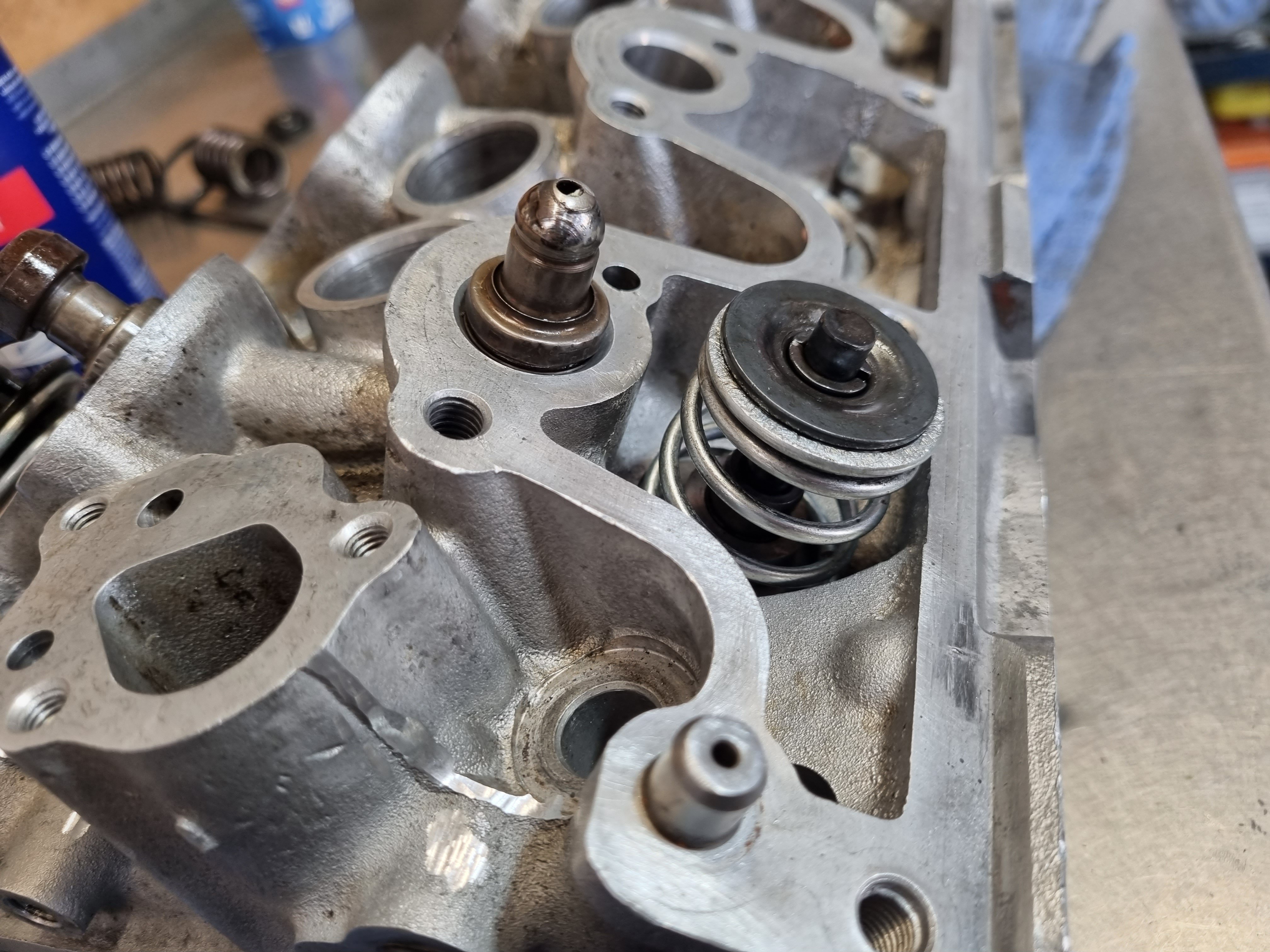
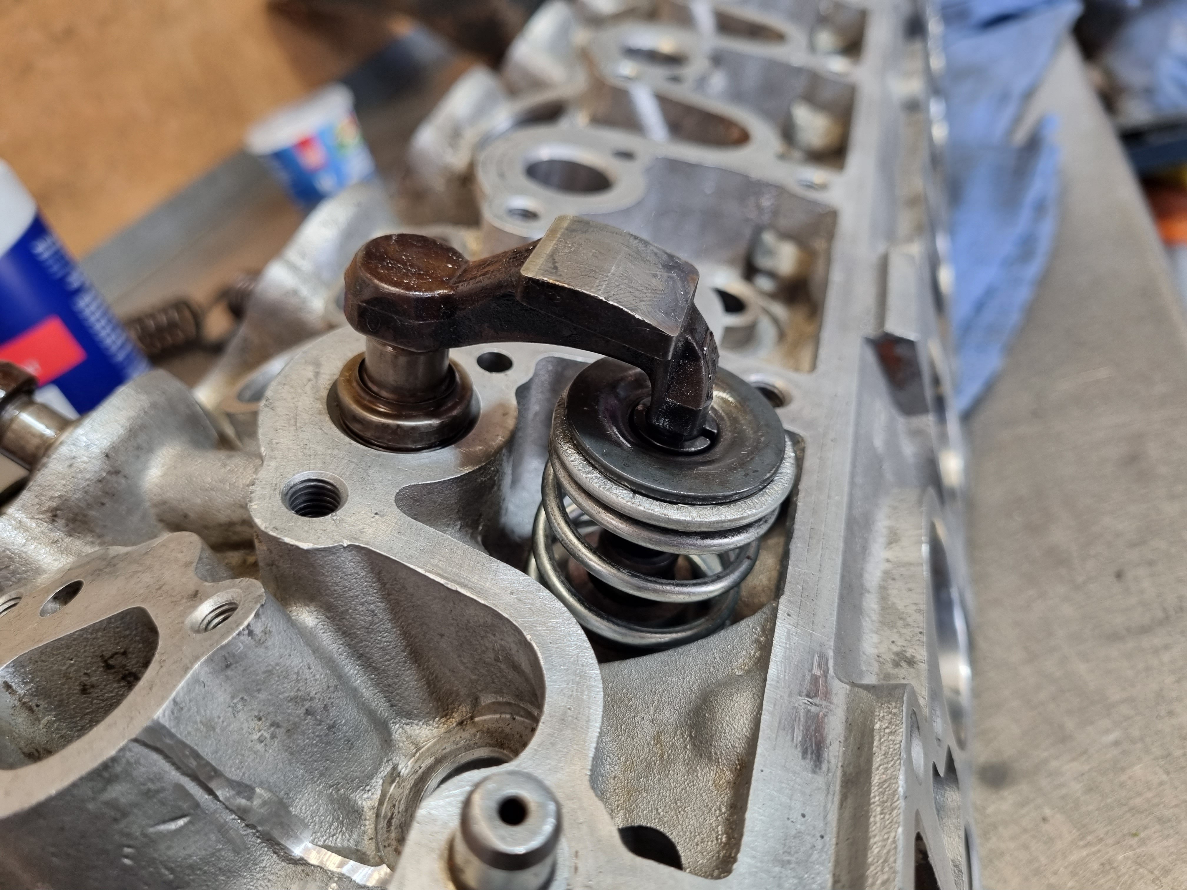
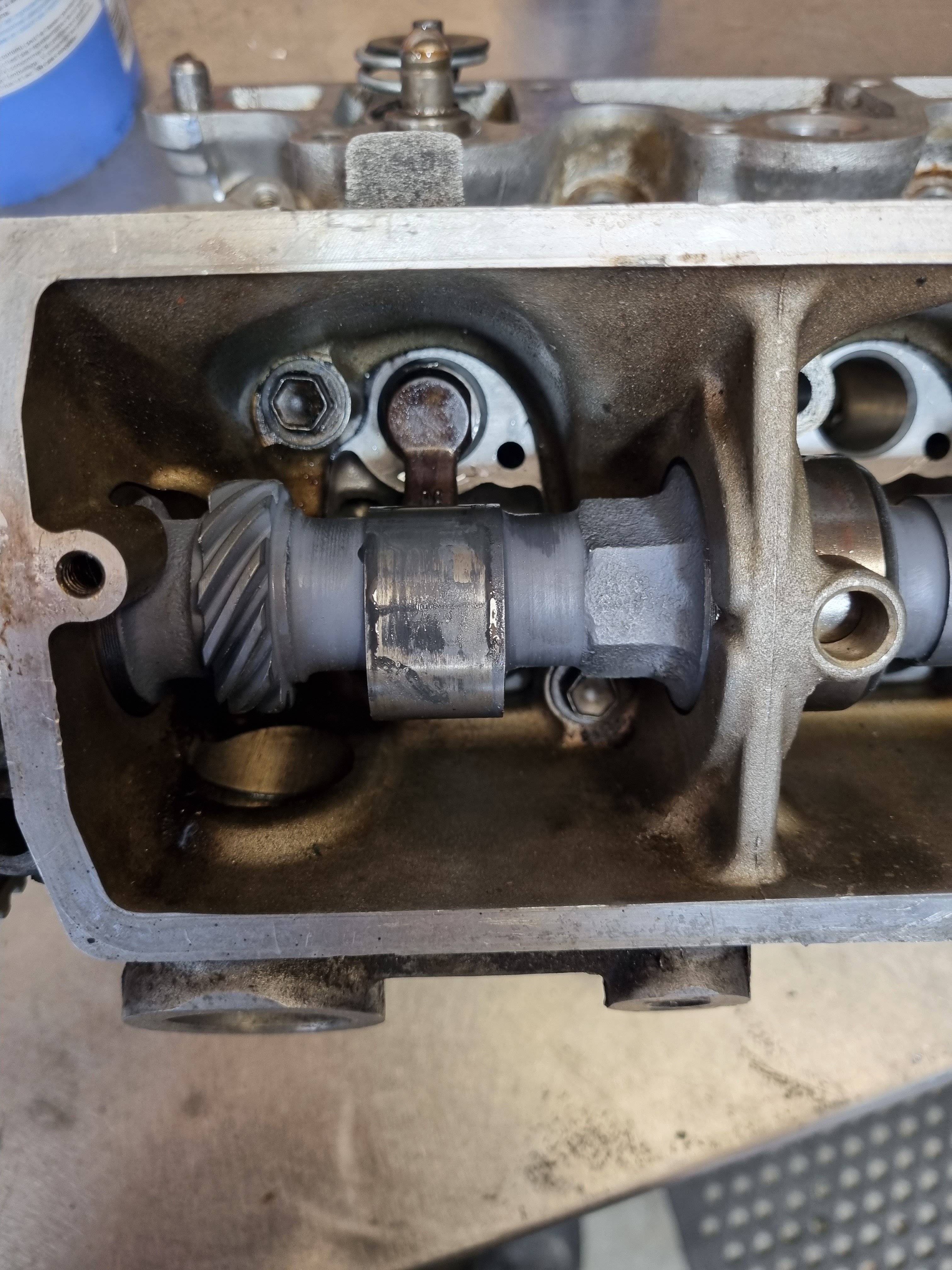
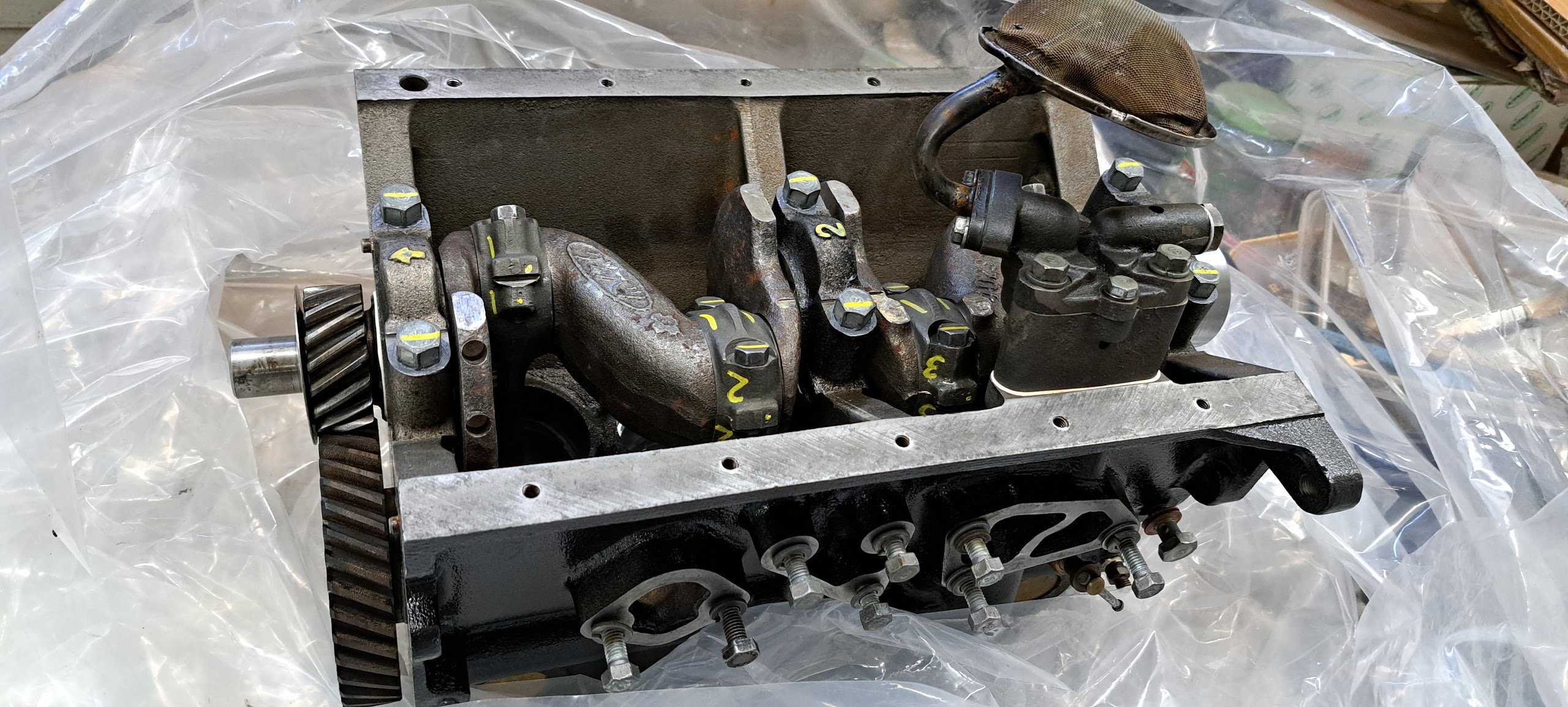
lifter discussion. so Clint rightly pointed out (in the wrong discussion thread) that the increase in pressure or flow to the lifter gallery could result in lifter pump up. i thought about this and did some more dummy assembly and reading. the Toyota lifters dont work the same way as a conventional V8 style lifter. you dont pre-load the lifter in any way and according to the factory manual they should work at full extension at all times and if they compress any more than half a mm they should be replaced. the lifters ive been using to test things have a spacer in them so they cant compress and are extend to max length, that way the clearances and interference i was measuring would be the absolute worst case scenario. the thing thats interesting/a bit concerning is that the lifter is designed (as far as i can tell) to live its whole life at max, or close to max extension. in my mock up assemblies there is no clearance between the cam and the cam follower. so if things get hot an expand a bit in theory it will open the valve on the back of the cam. im a bit confused by this because everything in this collection of mating parts is stock. the base circle of the cam has not been altered, everything is as it should be. i cant see how the non return valve inside the lifter can bleed a bit of pressure to allow the lifter to shorten when things heat up and expand? maybe im over thinking it and it will all just be fine, as i say everything is stock so it must work somehow? ill have to test it as i continue to build the motor. one good thing about having the oil pump driven off a lay shaft is i can spin the pump while the rest of the motor is stationary. that will allow me to experiment with things and see if the lifter will compress with oil pressure behind it.
1 point
-
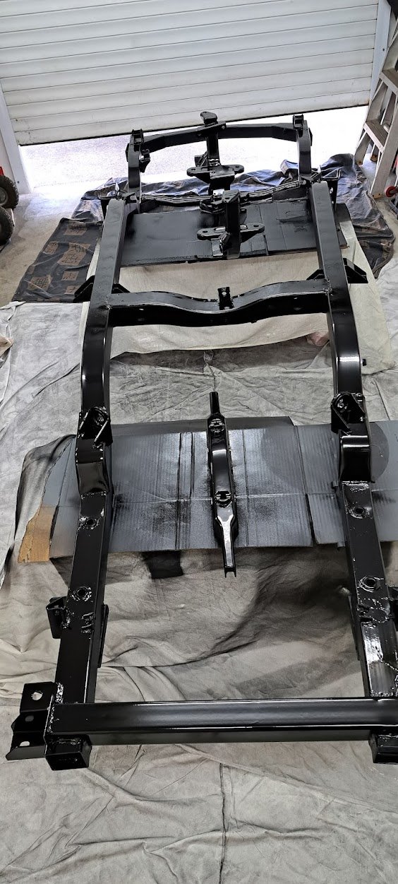
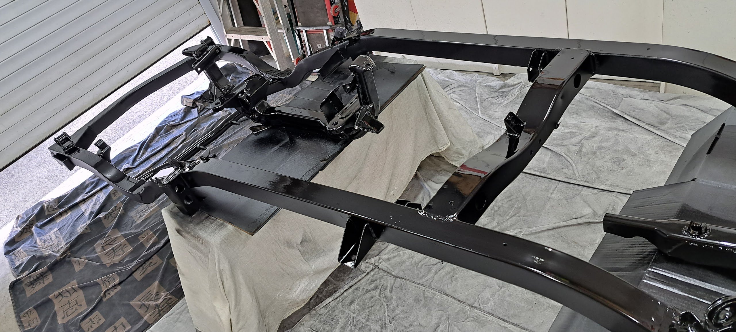
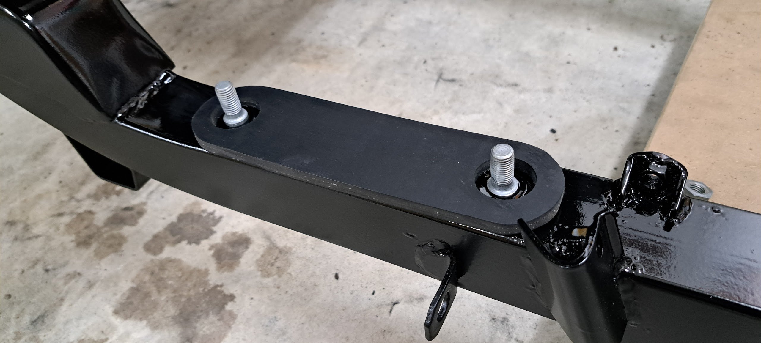
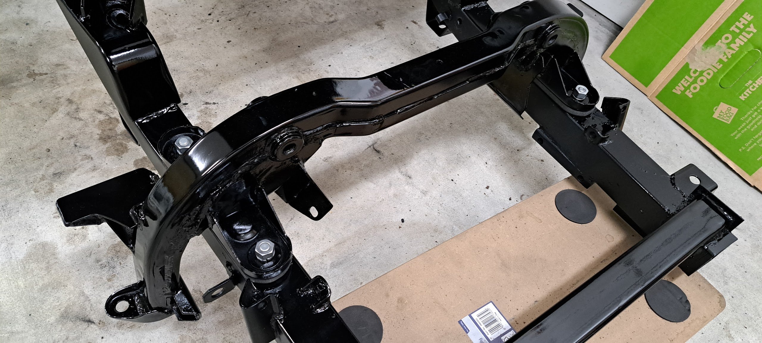
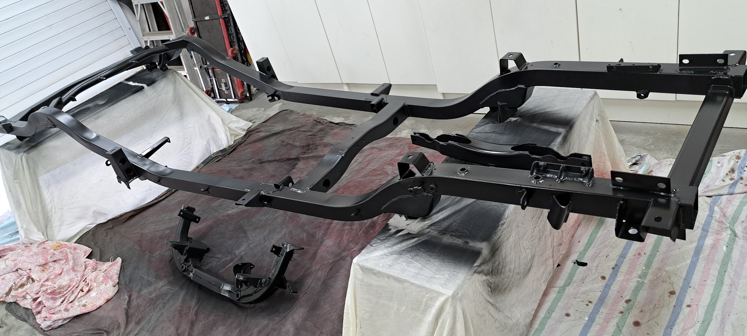
Chassis all painted in 2K black And reassembly started with the front engine cross member with new hand-cut rubber insert and plated bolts.
1 point
-
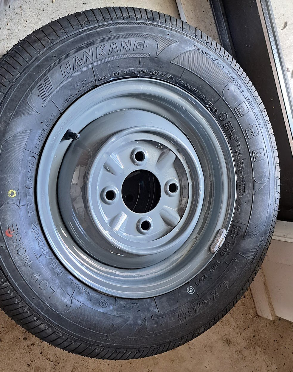
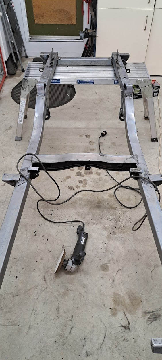
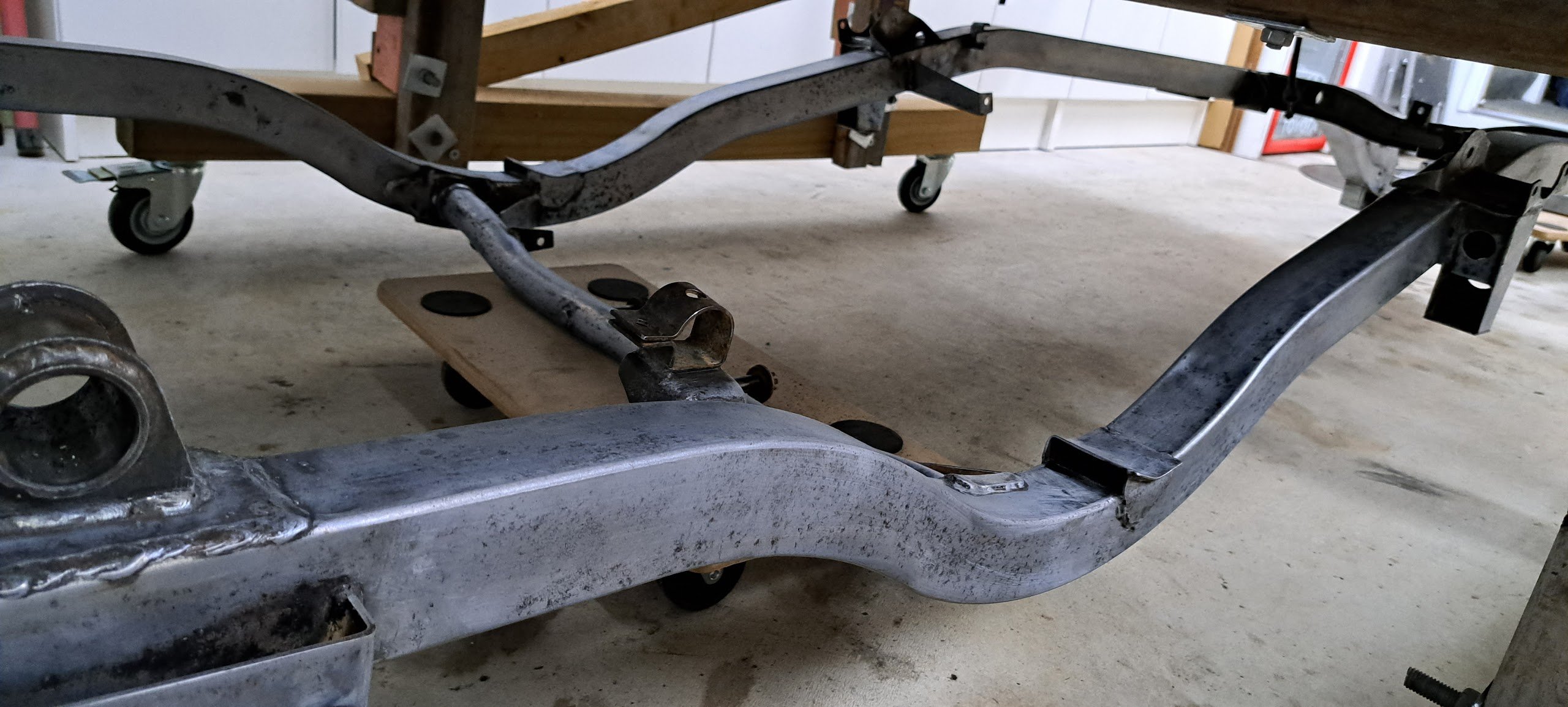
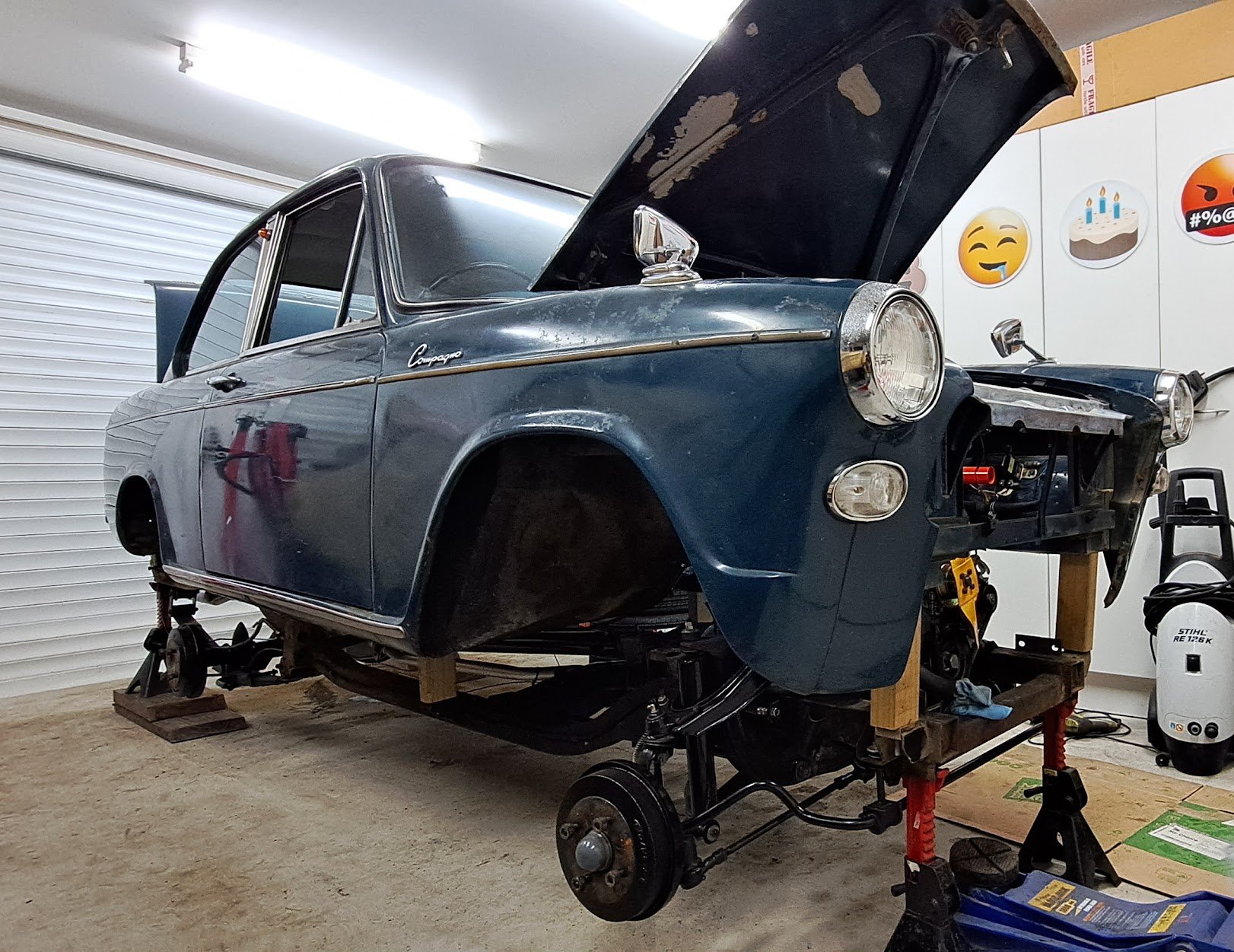
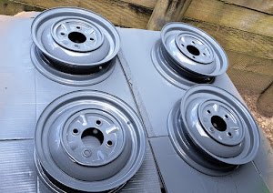
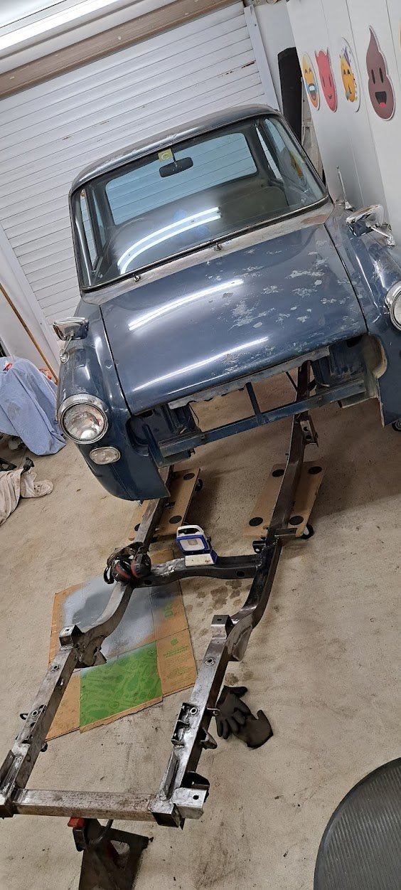
Overdue update - Body spaced off the chassis then the chassis removed completely then stripped everything off the chassis and epotec primed it Also acid dipped the wheels and straightened them up + painted them and some 155/80 R12 tyres fitted
1 point
-
No, purely hoarding them - Despite all advice to do something with them. Same goes for all of her bulldozers/hovercraft/heavy engineering equipment from the 30s to the 70s.1 point
-
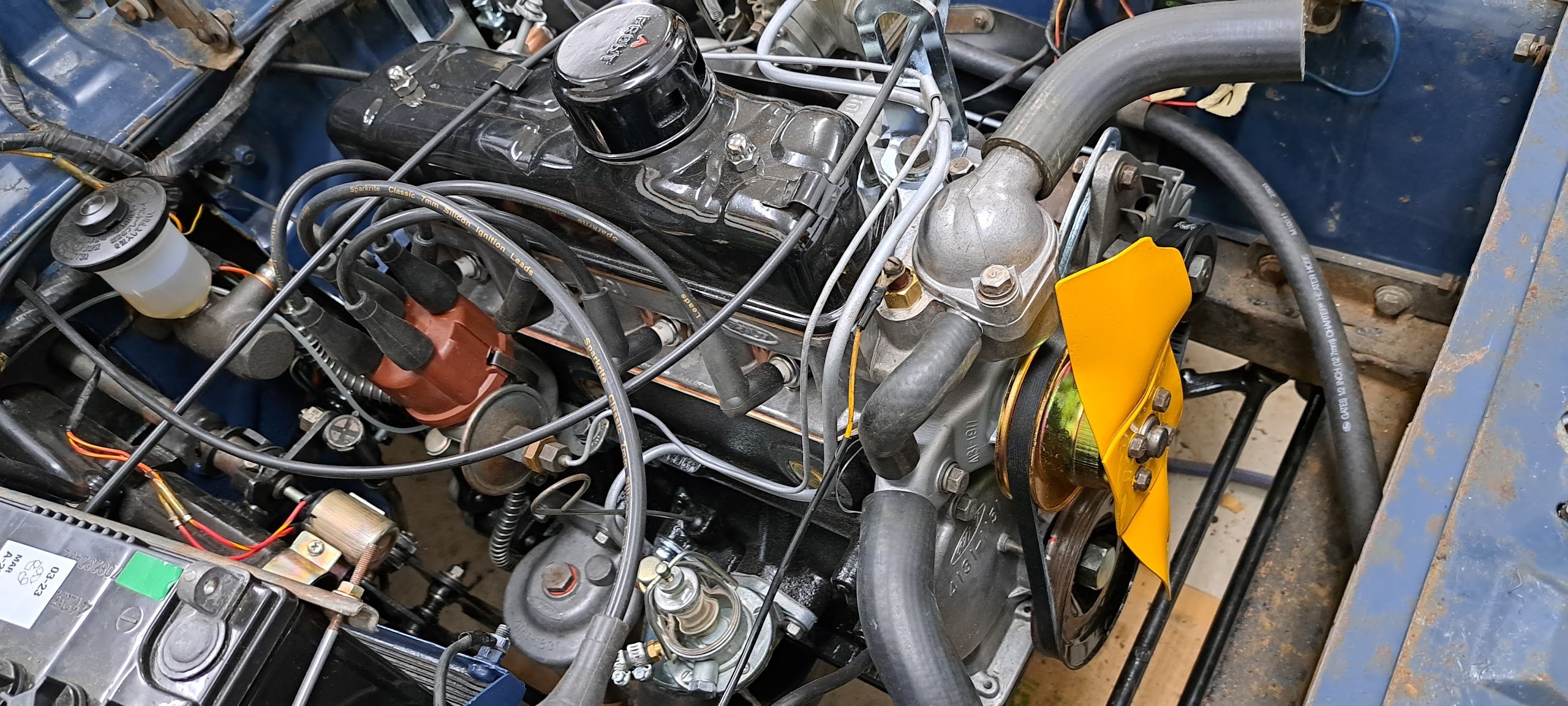
I fixed a couple of fuel leaks and a brake leak. Brake check in the video. Popping is the carb running a little lean without the filter. Alternator Voltage is way way too high at 17v so wont run it too much until that's sorted.1 point
-
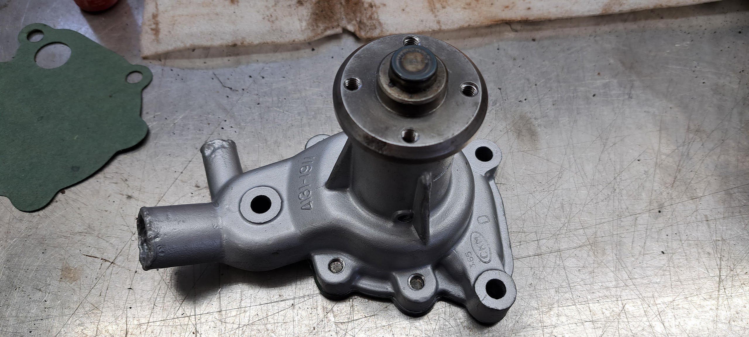
Water pump.. all clean and new I have to say that Gil from Waikato Engine reconditioners was awesome to deal with on this water pump - highly recommended and promptly fitted
1 point
-
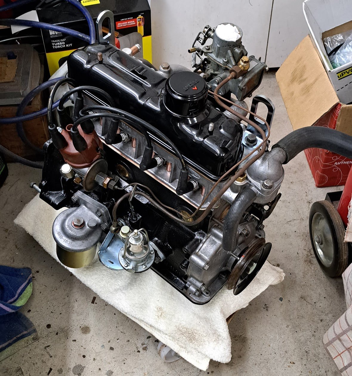
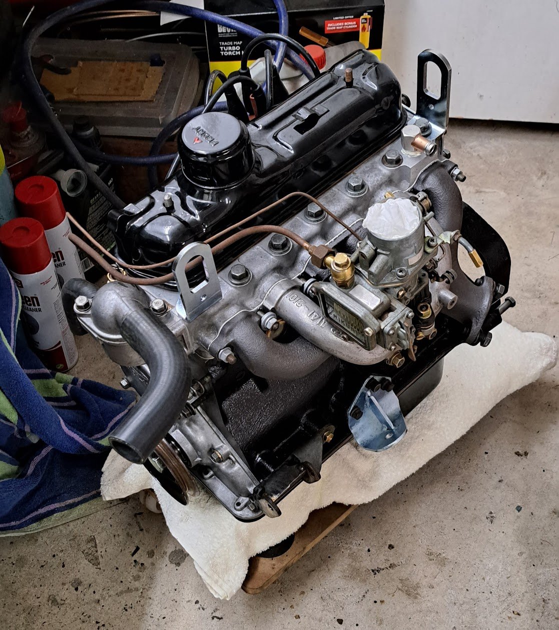
Getting there..
1 point
-
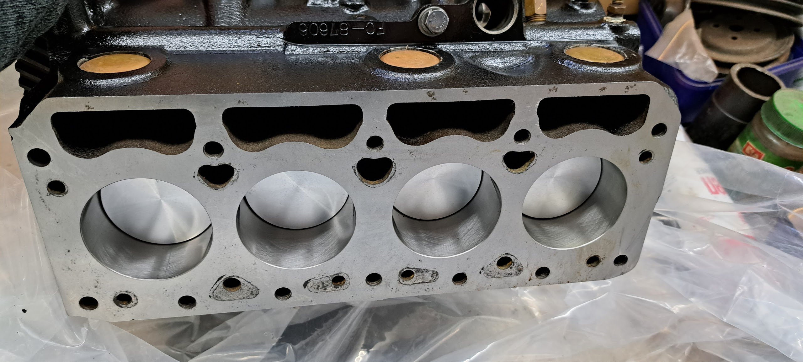
The Big Block is back pushing a whopping 877cc over the factory 797cc. It's also now high compression 9.7:1 vs 9.0:1 I have assembled some of it but awaiting a couple more parts incl the head plus custom head gasket.
1 point
-
Primed, painted and fitted
1 point
-
Hardboard cut today. Fits well.
1 point
-
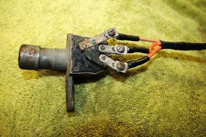
Got the horn and number plate light sorted. Number plate was just an earth wire. Horn was the steering column ring absolutely caked in corrosion. Quick buff up and the twins were tooting Promptly blew a headlight - so got them on order. Pulled the fuel tank and found it was absolutely rotten. Not surprising considering it sat 45 years with just a jam jar lid over the filler. New stainless steel one is being fabricated with the help of a local marine tank shop.
1 point
-
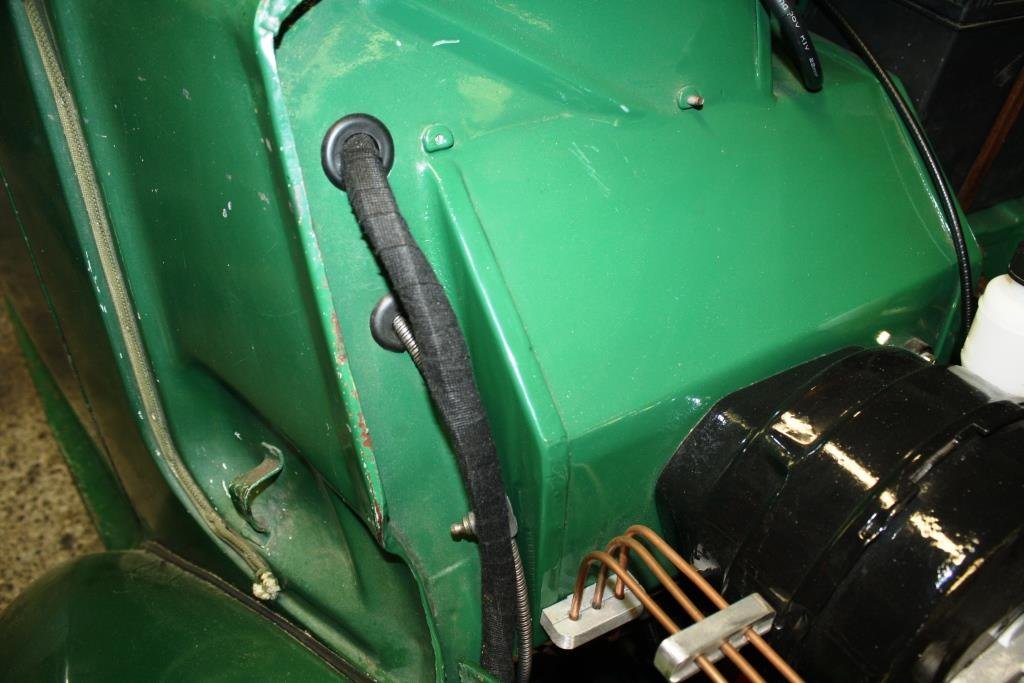
A lot of smaller "to-do" things achieved with a rather productive weekend just gone 1. Removed the "crunchy bar" boot rubber and replaced it 2. Cleaned and straightened the wiper arms/blades and replaced with new refills 3. Windscreen washer (from a mini) fitted to the original bracket as the original had crumbled to bits. + new pipe 4. Removed the heater box, pulled out the core/tap and cleaned out all the old crud. freed up the tap too New heater hoses too 5 .Made some new rubber flappy doohickeys to stop mud splashing into the engine bay 6. Fitted the drivers side Compagno badge I got from Japan
1 point
-
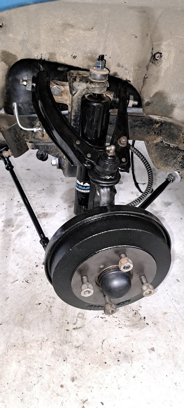
GRRRRR .. Pistons arrived from the UK... wrong size Stern words later and it turns out their supplier put +040 wrong pistons in a +020 labelled box!!! And to make matters worse they had correct +020 rings so that combo doesn't work so another set of triple checked correct ones are on their way via pronto post... albeit after some dude gets a crown on his noggin and they get a day off for it! In the meantime... Yucky, mucky, sucky front suspension Is now all black blingy goodness
1 point
-
Unobtanium has been found!! Chatting to another owner of a convertible one of these in Aussie and i asked about the wheel cylinders. He mentioned all his were re-sleeved but had heard that some Subaru ones matched. This little titbit of info sparked some research and I found a Subaru Brat/Brumby/Leone rear cylinder that looked the same. I purchased a pair and compared them - the main housing is the same but the piston/rod setup is different. However swapping in my old pistons to the new housing and using the new dust boots works perfectly
1 point
-
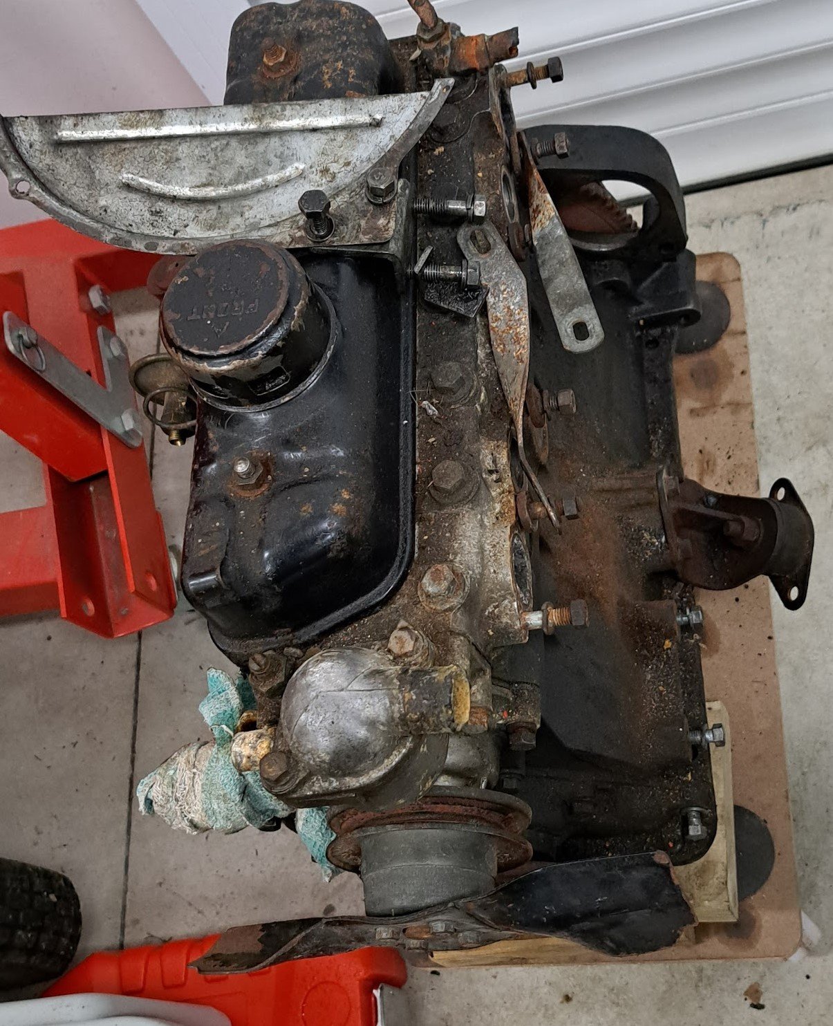
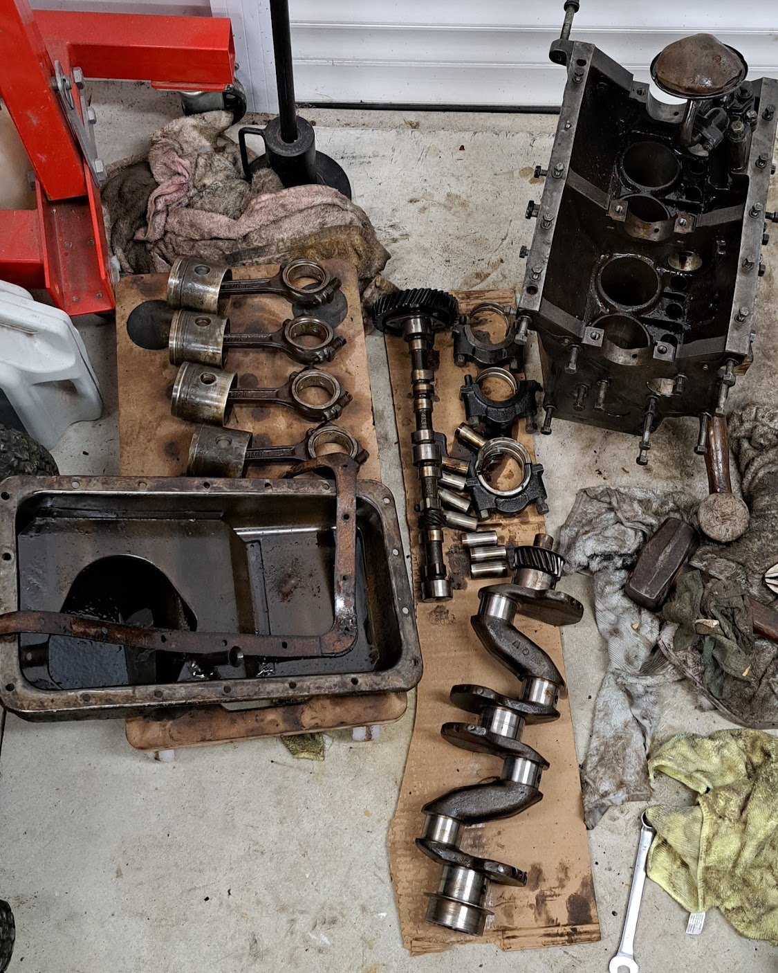
Xmas break.... too much time on my hands... No matter what i did the engine wouldn't budge so i figured it had to come out. and pulled it all apart as the pistons needed some gentle coaxing (BIG HAMMER) to get them out. Plan is to rebuild it with new pistons and bearings plus a tidy up.
1 point
-
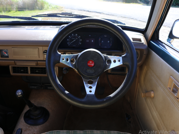
Interior wise I think I will keep modifications to a minimum at this stage. If in the future the scope creeps up, i'll get some period correct front seats and try to match the original pattern as much as possible but for the mean time I did want to do something about the steering wheel. I picked up a wood grain Kaizen steering wheel which I believe (correct me if I am wrong) is from a late 70s early 80s land cruiser and was an optional wheel from factory. The only issue there is I have had a hard time sourcing a horn button that fits. All the ones I have seen for sale at 51mm inside DIA and by calculations I need a 56mm one. If anyone has a toyota horn that suits, i'd love to hear from you. I also managed to get my hands on a Wildcat wheel with a Toyota horn button which suits my application perfectly. I love the feeling of the wild cat, it's small, comfortable to wield and period correct. Fortunately, the wheel came with the boss kit as well which can be hard to come by. I did have to do some minor modifications to it for the horn to work consistently, gave it a good polish and slapped it on. Stiffer suspension, excellent tyres and now a smaller steering wheel has made a world of difference in terms of drivability. A+ would trade again
1 point
-
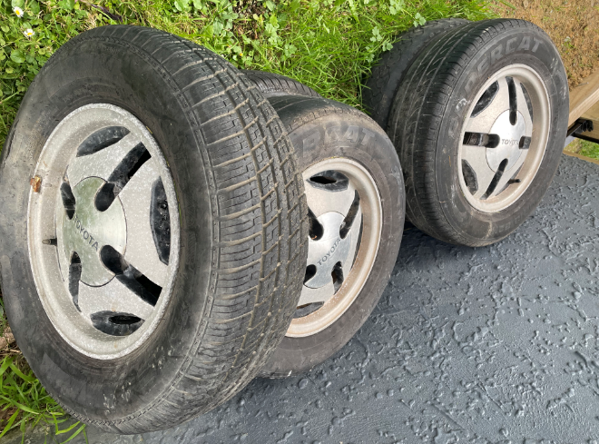
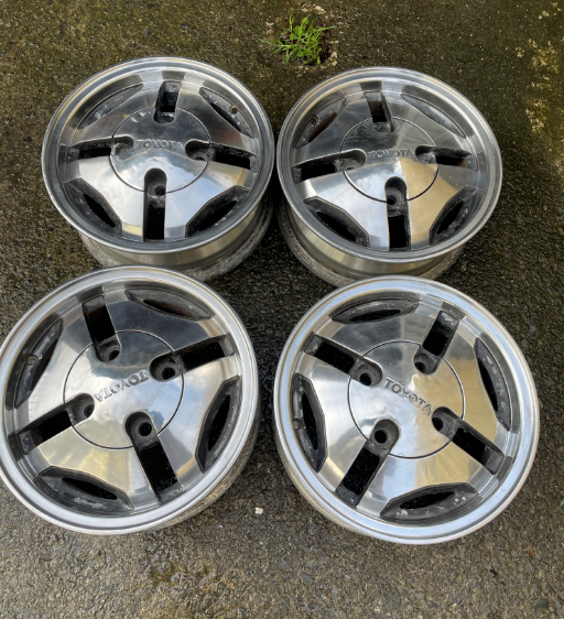
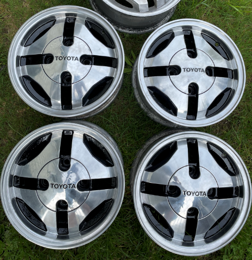
Now that the KP isn't feeling like a boat anymore, I had to address the wheel and tyre situation. Continuing with the OEM+/Maintained vibe, I wanted to get my hands on a set of KP61 sprint wheels. I managed to get my hands on a pretty run down set but I was optimistic that I could make them look cool again. I spent several hours cleaning and polishing before the optimism ran out and I gave up and started to look around for somewhere to do it. I actually ended up searching the forum and I found a post from 2009 mentioning a potential lead. I gave him a call surely enough he was still doing it for funzies They came out pretty neat I then spent many hours with some sand paper, a couple of different paint brushes and some black engine enamel paint I wrapped them in some Yokohama A539's, got a wheel alignment and put them on. So far they have outlasted the mighty 2k engine. I used to collect stickers back in the days and had an reproduced rego sticker that I had intended to use on a different but I never ended up using it. Same year too which is cool
1 point
-
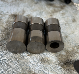
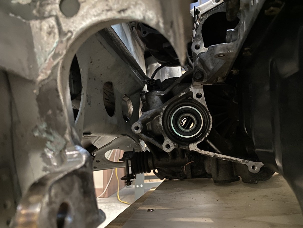
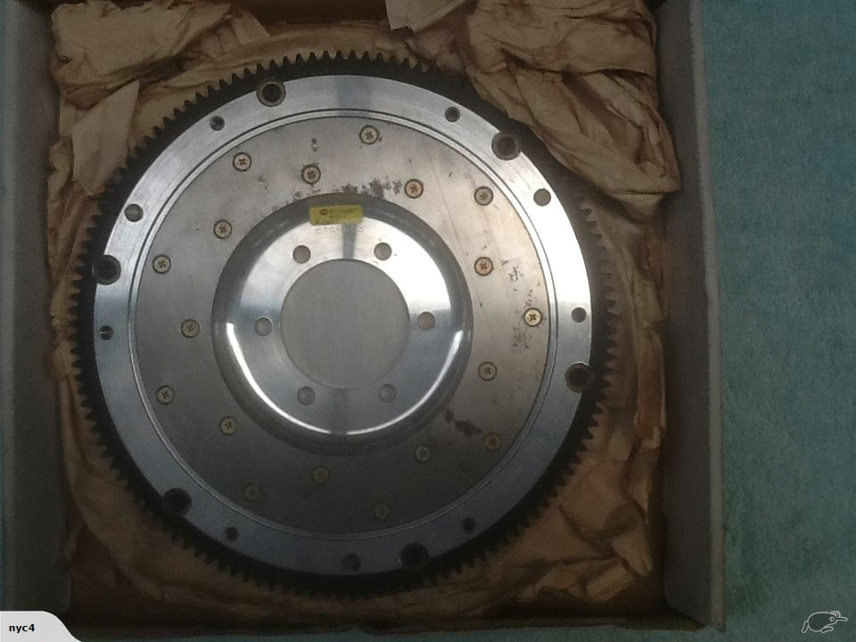
So now here we are six months later and I've come to my second of two one week holidays for the year. This whole time I've still been mentally working on the car, thinking through all sorts of different problems and making plans and drawings along the way. Now I've had some time off from school, I made a trip back up home and put one of these plans into practice. However, before I can get into that, we have to go through a little story time first... It's long been playing on my mind the fact that I'd still not fully completed the V6 RWD conversion. Sure I'd made the adapter plate, engine and box mounts, intake setup, and sump etc, but the actual connection between engine and gearbox was still missing. The flywheel and clutch situation has been through a few revisions, both in my head and in physical work. You may remember from these posts: that I planned to use the standard V6 flywheel with an extra ring added to increase the outer diameter to take an RX8 ring gear as well as a spacer to bring it out the correct distance to take run the RX8 clutch and pressure plate. After making the spacer (which if I'm honest now I wasn't particularly happy with my workmanship and tolerances anyway) I found that the RX8 friction disk wouldn't work with the V6 flywheel or pressure plate, meaning I would have to adapt the RX8 pressure plate to the flywheel. So upon taking it to the machinist to get his opinion on making the adaptations for the larger ring gear and pressure plate, we found that pressure plate bolt holes would end up directly on the junction between flywheel and adapter ring. This was doable but it was far from ideal. Also, the labour involved would have cost similar amounts to a fully custom flywheel anyway and thus the whole plan was put on hold for a while. You may indeed have noticed this in the complete lack of a mention of the clutch and flywheel in the following posts. And so came about my next plan. Ever since reading @yoeddynz's viva thread, I'd been pretty keen on using a lightened flywheel to help unleash the engine's propensity for revs. Luckily, this was going to let me kill two birds with one stone. I'd decided long ago that I wanted to keep everything inside the bellhousing exchangeable with standard RX8 parts. This will allow me plenty of potential clutch upgrade options in the future. With that in mind, I went looking for RX8 lightened flywheels. Almost exclusively, lightened rotary flywheels are designed to bolt up to the automatic counterweight, rather than using the integral counterweight cast into the standard flywheels. This made my life much easier. Now I could make an adapter that picks up the six holes in the flywheel, spaces it the correct distance to use the standard RX8 clutch and pressure plate, and bolts to the end of the crank like the normal V6 flywheel. Essentially I can make a counterweight emulator. The next step was to decide the material to make my adapter out of. I could of course just use any old steel billet lying around the shop but my fondness for my feet kind of convinced me not to go that route. So I looked at what material is usually used for steel lightweight flywheels and found that 1045 is common. I figure if it's strong enough to take the forces on a whole flywheel, then it should be well strong enough for my much smaller diameter adapter. Next, I had to take measurements of everything and design the actual adapter itself. And this is what I came up with. You'll have to thank the American's for building the majority of commercial aircraft in service for my use of imperial measurements. Almost all the tools used in the industry are in imperial and because of that, all the tools I had available at school are as well. Anyway, according to these dimensions, the ring gear should end up in the same position as the RX8 relative to the bell housing face and starter, and therefore the rest of the clutch system should work as normal as well. With all this done, I could finally go home and get stuck into it. Step one, of course, was to get the raw material into a useable state by facing it up and generally roughing it out. Thank god for power feeds and tungsten carbide tools. Next, I turned the recess that fits over the end of the crank concentric to the outer diameter of the material. With that done, I turned the piece end for end and dialed everything back up in the four jaw to turn the spigot that that flywheel runs on. This is also concentric to the outer diameter and, by extension, the recess as well. This is obviously crucial to avoid vibrations and undue wear on bearings and so forth. You'll also notice the stepped section on the front of the spigot. This is designed to fit the inside of the standard flywheel for reasons that will become clear later on. With those surfaces all machined, the crucial dimensions are done and I can have a nice big exhale. This means I can move on to less nail-biting procedures. One thing I did learn from the first spacer I made way back in the day is that measuring and drilling PCDs is a right royal pain and very difficult to do accurately with the tools I have available. So this time around I decided to forgo any and all measuring of PCDs entirely and use a far more analog method. I already have the PCD that I'm trying to match. Why would I not use it to guide my drill bit? So with that in mind, I made up some bushes to guide the pilot and tapping drill and protect the aluminium flywheel. Next, I clamped the flywheel and adapter together and shifted everything to the drill press. You can see the bush already in place in this photo. Once I had the first hole drilled to size, I tapped it to M10 x 1.25, which is the thread used by Mazda on the automatic counterweight that this flywheel is designed to bolt to. With the first hole tapped, I bolted the flywheel to the adapter, which let me get rid of the whole clamp setup and drill the subsequent holes much more simply. I used a similar setup for drilling the crank bolts too. I wasn't nearly as worried about damaging this flywheel since I won't be using it once it's done its jig job, so I only used a bush for the pilot drill and just threw the final drill through using the flywheel itself as the bush. Now that all the holes were drilled I decided I ought to check my tapped threads for strength now, rather than do all the rest of the work just to find that they strip as soon as I try to put any torque on them and junk the workpiece. So I throw the first bolt in and torque it to the high limit of the 32 - 45 ftlbs recommended by Mazda for the flexplate bolts. It goes tight, tight, tight, still tight, still turning, still turning, shit. I figure its stripped and fucked. So out it comes and sure enough, the bolt thread is gone burgers. However, the female threads are still pristine. Stoked. So in goes round two. Tight, tight, tight, still tight, still turning, still turning, shit. Again. So, out she comes and another bolt failure. This time it stretched the crap out of the bolt but still left the threads perfect. Third time was the charm though and all the threads eventually took the torque like champs. Guess that teaches me for using the first bolts I find lying around. Finally, I put everything back into the four jaw and faced something like 15mm off the spigot to bring it back to flush with the flywheel face and finalise the outside dimensions. Here you can see me checking the runout of the flywheel when mounted and it was well well within the 0.008" tolerance specified by the Mazda service manual. Finally I bored the recess for the spigot bearing. I decided to use the MX6 spigot bearing, mainly because I had one available, but also because it fits the RX8 input shaft perfectly, and it was much easier to machine the larger bore for than the much smaller stock roller bearing used on the RX8. It's a very light press fit, able to be tapped home with a mallet just like the fit in the original V6 flywheel it came out of. Finally, after two straight 14 hour days on this thing, I was ready for a dry fit. I used the longer crank bolts that I bought for the first spacer which gave me shed loads of thread engagement, as well as a couple of M10 bolts I had lying around for the flywheel itself. I'll get some proper high tensile ones later on. Next was the clutch and pressure plate which I eyeballed the alignment of and used some more M8 bolts I had lying around. Finally, I muscled the gearbox around and offered it up. With the engine and box somewhat leveled the input shaft slid right in and home over the adapter plate dowels. A couple of bolts later and I stood back to admire my handiwork. It is a beautiful thing indeed. I couldn't help myself at this point and threw a driveshaft in the back end and a ratchet on the front and low and behold we have drive!! I have to apologise for the photo quality at this point. I think there's a smudge on the inside of my lense somehow and it wasn't having a great time with the fluorescent lights at 1:30 in the morning. I ran it through all the gears and checked the disengagement with the BFC in the bottom of the frame, and it does indeed stop spinning the driveshaft with the clutch in while still having a small amount of wiggle to the arm when out. I also checked the starter engagement with some white paint pen and it looks to be exactly where the existing wear marks are on the starter gear. I'd have loved to hook up a battery and some jumper leads to spin it over with the starter but I did end up running out of time. With all said and done I am absolutely stoked with how everything worked out. My measurements and calculations were apparently right on the money, and my machining workmanship and tolerances are leaps and bounds ahead of the spacer I made initially. The final setup for my adapter situation comes out to this: Custom 12mm steel engine to gearbox adapter plate of my own design Custom 1045 steel flywheel adapter of my own design Aftermarket RX8/Turbo RX7 lightweight aluminium flywheel 6 speed RX8/Turbo RX7 clutch and flywheel MX6 spigot bearing Stock RX8 clutch arm/release bearing If you've made it this far though what was a whole afternoon of typing then thank you very much for reading. I'd appreciate any comments or feedback on my discussion thread which you can find here: That's it for now. Hopefully won't be another six months before the next update but we'll have to see what happens. Cheers.
1 point

.jpg.9298a81b37527e20991ea9282033a829.jpg)


.thumb.jpeg.e0a4bff61111e0c8c7396950fcc94da1.jpeg)


This leaderboard is set to Auckland/GMT+12:00