
Leaderboard


Popular Content
Showing content with the highest reputation on 03/04/24 in all areas
-
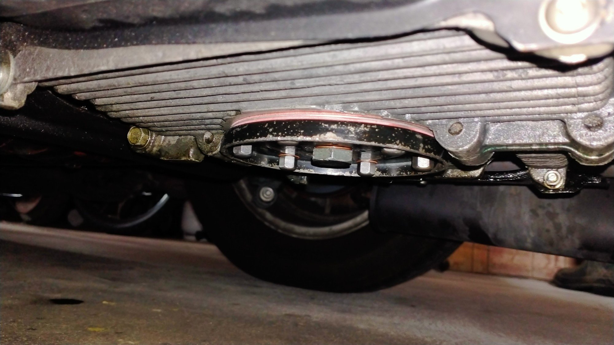
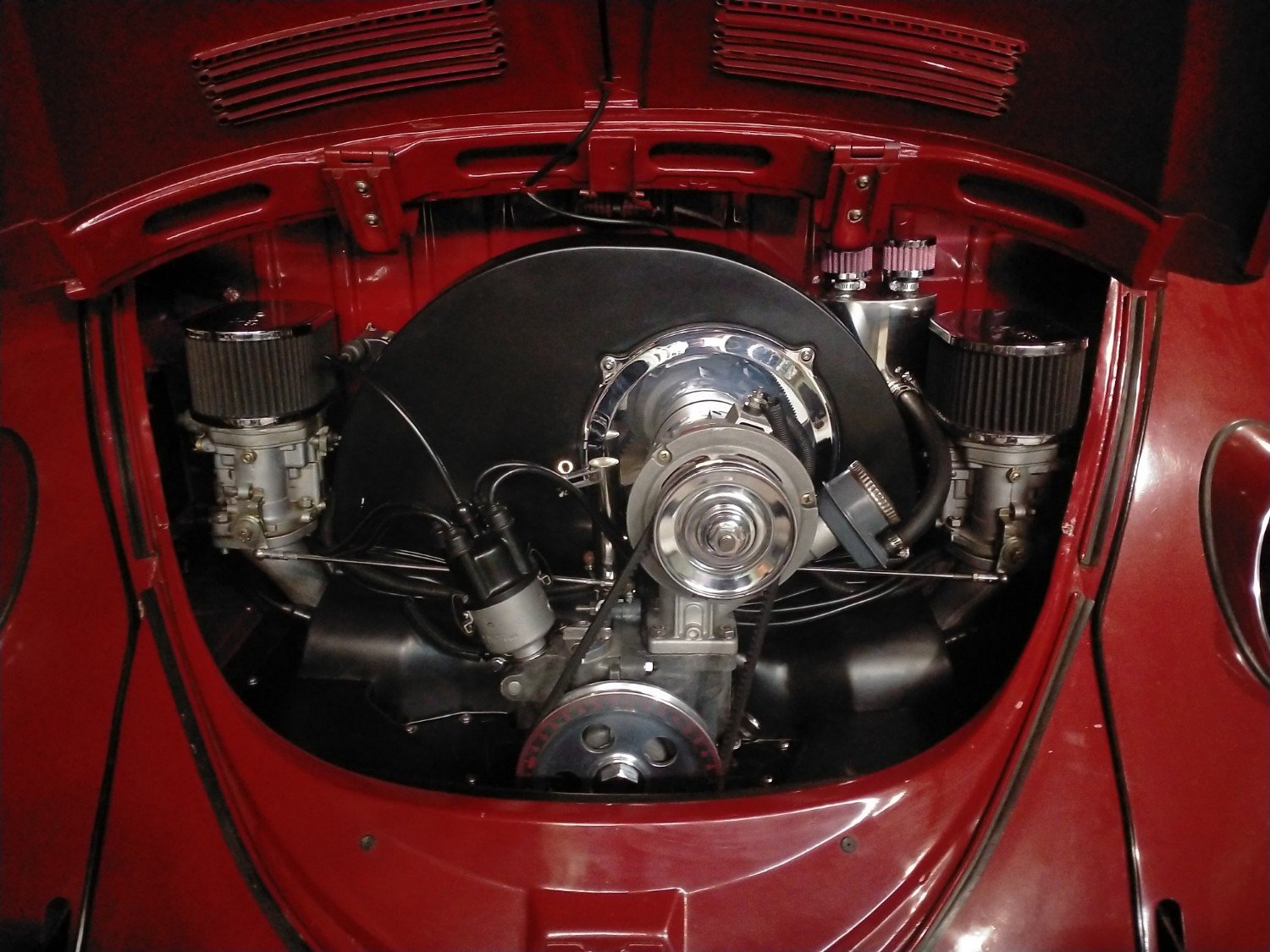
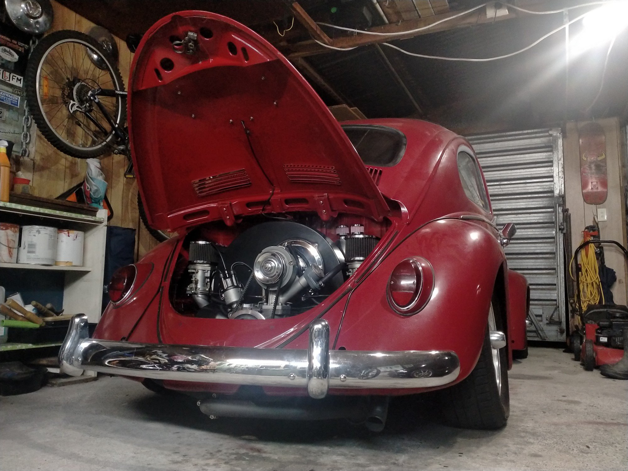
Always looks better after a wash. And from my favourite angle. Finally got around to changing the oil, really should have been done sooner, there was so much crap in the sump, all that lifter paste. VW's don't really have a sump, or a filter, just a sump plate with a tea strainer around the pick up. Ignore the big square sump in the picture, that's aftermarket and my car is probably to low for such things All was going well until I went to reinstall the tea strainer plate arrangement. The gaskets in the oil change kit have recently gotten at least three times thicker, so now the six little studs are getting very short. Only had just enough engagement, one but had to go sans crush washer. Have continued tuning the carbs, @sluggy suggested cranking the accelerator pumps, so I've been doing a little at a time, everytime it's gets a little better and nicer to drive, idle is very low but very smooth and doesn't stall, just seems weird not having it shake the car at the lights. Mrs even commented on it.
 15 points
 -
I've been chipping away a fair bit lately. I managed to find some radiator suport panels. This was my first time doing any sort of panel work, after a fair bit of tweeking I managed to get them good enough to where I was happy. I also filled in the 2 big holes in the engine bay. Years ago I hacked off the washer bottle mount to make room, luckily I kept the remains of it. I made new ends for it to replace the bits I hacked away. Replaced the battery tray. I did a test fit of the engine to sort a few things out. The main things were the gearbox cross member and where to fit a clutch master cylinder and sorting the exhaust. Not a hell of a lot of room, but it worked out OK. The wee fella helped modify a toyota gearbox cross member. I've just finished painting the engine bay today. It's not going to win any awards, but I'm happy enough with it. I'll start the final reassembly now. I sorted out the flywheel/clutch issue too. The guys who did the engine work (Kennally Cams) did some magic to the fly wheel and machined it to accept shouldered bolts to locate the pressure plate as it's being torqued down. Hopefully this week I'll get the engine in for the last time.12 points
-
Back home in Porirua. I picked up another set of wheels that are looking pretty schmick. Recaro seats are also in after drilling one hole in each of the factory Toyota runners. Exhaust fell off on the way to Shannon but easily fixed with tie wire.
10 points
-
I glooped the two halves together, bolted them up, bolted the tailhousing on and let it set. Following morning it was bolted onto the engine, unsurprisingly a bit heftier with all the gubbins placed back within the box. Its about 9kg heavier than the standard imp box. I then started to fit the first part of the gearshift linkage. The first of those snazzy universal joints, handily available in a diameter to suit the shifter shaft on the Subaru box. I just needed to add a small locating hole for the grub screw... Universal in place.. Engine and box were then bolted back into the car. This bit is so quick and easy when using the 'engine stand 2000'. It takes about 10 mins and I'm getting quicker. It'll be slower when there's shift linkage to undo and driveshafts to slip out of the way. But at least the main heavy awkward part is actually easy. That lot in place I took some pics. Its neat to be able to look out from the one of the lounge room windows down onto the workshop floor and see this... With that lot in place I was able to suss out the angles I could get away with, as shallow as possible and allowing for the handbrake mechanism. I had this old imp gearstick assembly that @dmulally kindly posted over to me. Some previous owner of the car he got it from liked painting things. Everything. Multiple times... I scraped all the layers off, took it apart and cleaned off the dirty old grease. Discovered it had been cobbled together from two old shifter bases. It was originally a very early Imp unit when the very first cars had an automatic choke, which often proved problematic. Hillman then changed the cars over to a manual choke with a nifty little lever in front of the shifter. This mount had been added to the early base. Which means they must have chopped up a later baseplate to get the choke mount. Why they didn't just fit the entire newer base plate I don't know. But what I had in front of me was a frankenstein of base plates with barry spec welding and fixes, but also including a not too badly made bronze bush on the lever where there is normally a (wornout) plastic bush. I had a couple of shift rods to choose from. I chose the least worn. Moving back to the gearbox end I machined up some shaft ends from stainless bar to suit the universal joints. I had some stainless tube and welded the ends in place on the first shaft that runs from the gearbox universal down to the tunnel. Now I needed a sturdy, slippery support to mount in place of the second universal joint. This will not only take back and forth movement on the shaft but also a bit of thrust loading created by the angle on the connecting shaft. I had already bought a lump of slippery hard engineering plastic with this application in mind when I had ordered the plastic for the flywheel thrust bearing a while back. It was bright yellow. Luckily not seen under the car as it would clash with the blue paint. I put a hole in it and machined the outside down. Which also created a pile of pretty swarf.. Then reamed it out to 1" Still a bit tight so out with the adjustable reamers.. until it was just right... Then made a stainless cradle .. The cradle got some wings welded in place and I dug the rivnut tool out.. Mount now bolted in place in the tunnel I had to chop the last tube to the right length, weld on the end and bolt the universal in place.. The front end below the shifter was was standard imp stuff and this is where problems popped up to throw a medium sized spanner in my workings. The side to side gearstick movement across the gate was minimal. Ridiculously so. Like about 1". Or 25mm in new money. Yet the fore and aft movement was about right. But quite stiff. I was contemplating why this was so and what I could do to remedy this when I also noted that 1st gear was where 3rd was and 3rd was where 1st was. Poos. Four years ago when I had compared the Subaru gearshift pattern at the box to the imp unit I thought they were exactly the same. But I had not accounted for the reverse rotation taking place under the imp gearstick. Also I never really thought much about how little of rotation the Subaru box needed on its shifter shaft to shift the internal selector across the 3 rods. Its a tiny amount, like 3 degrees say. Whereas the Imp box has a shorter internal selector and requires more rotation at the shaft. Hence the Imps gearstick knob only moves a teeny bit when coupled to the Subaru box. But the Subaru box has a standard/similar amount of rod movement within (ie 1-2 and 3-4th) which was going to make things trickier to fix. Simple linkage/leverage multiplications that is easier to see than explain. Sorry if your brain hurts. I had to hurt my brain a little bit to suss out a solution but there was only a little bit of smoke. The reason the scooby box is different becomes obvious when you see the scooby shifter setup. Which luckily I can show you because last week thanks to @Leone I was put onto a local fella to me who happens to have many old Leones and Brats kicking about his property and he had a spare leone front wheel drive box that I wanted (always handy just in case...) His property is amazing!!! Long 4wd only driveway up to a ridgetop house with stunning views out over Tasman Bay. Old leones just kicking about... Luckily we have our trusty old 4wd Hiace and that became the days gearbox transporter... Box on bench. Look at that shifter mechanism... The shifter rod attached to the gearstick only rotates a tiny amount when the stick is moved sideways across the gate. But the rod moves 10mm in each direction when shifting for and aft. Simple. Robust. Very Subaru. I can't copy it though because I have turned my box 180 degrees. No matter where I put my pivot point (below or above) I'll have one of the planes working backwards. So I decided to build a new shifter base setup. The most important thing was to reverse the rotation so the gearstick pattern is correct. The imp pivot point needed raising to allow the offset shaft end to be rotated to above rather than below the centre line, so reversing the across gate movement. I would add the ability to adjust both rotation and lineal movement. Started with a new pivot cup because I was not happy with the worn and Barried pressed steel item.. I dug out a large lump of steel bar... Chopped out a square and cleaned it up in the mill.. Big drill = big hole.. Rough machined out a cup shape. Cut a form in cardboard to suit the brass ball and used a die grinder bit to finish the shape... Grinding paste time... Slots for pivot pin.. Lightened the lump down.. Built the shaft up with weld and machined it down so I could add a lower pivot point. Milled some steel like so.. Welded a boss on.. New socket for shift lever ball end... Cut out Barrys previous workmanship... Machined up some spacers and a base plate.. Welded up a little tower (my stainless and steel tig welding is definitely improving, helped muchly by realising that not being able to see what I'm doing does not help much and finally admitting to my age and buying some reading glasses....) Welded tower to base.. Now all together please... Bolted together. You can spot the adjustable rotation, which the spacers allow for, along with adjustable pivot point. In place... Yay- it works! The shift pattern is correct and the action is much smoother. The spring loaded indents on the internal gearbox shift rods are quite stiff, which I noted was the same on the other box with its stock shifter. Its a bit baulky to push past the synchro baulk rings into gear but I think will feel better when the gears are actually rotating. There's certainly no slop in the system and it feels very mechanical - not rubbery. I now note how much flex there is around the shifter base in the imps tunnel (granted a very rusty shell..) Its something I might just try to stiffen up on my blue Imp when fitting this lot in. Phew. That was a little mini engineering mission I was not expecting but that's this project in general9 points
-
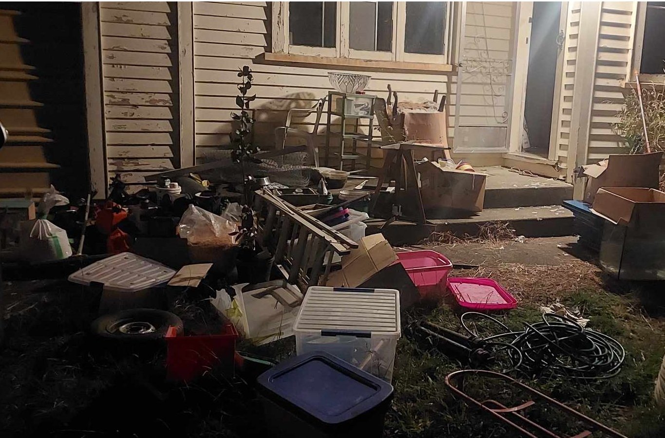
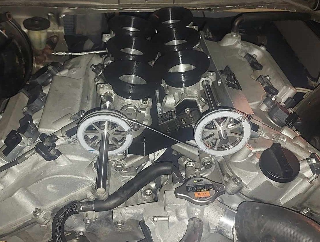
Alright so as of yesterday I'm finally out of mortgage prison! I finished moving house with heaps of time to spare, I definitely wasnt biffing trailer loads of stuff onto the lawn the night before settlement. I got some throttle pulleys cut from stainless. I'll put a radius on the inside of the pulley edges and deburr a few spots, but on the whole they came out really nicely. Quite heavy though, probably could have made some parts thinner. (Everything 2mm stainless) It's looking like it'll be fiddlier than expected to balance the cable length and pulley positions to get the banks even. One thing that I didnt take into account is that there is no tolerance for having a cable that is "overlength" as you physically cant slide the protruding end of the cable into the pulley. However I could probably chop out the relevant section of the pulley to allow this without any issues, as these are still significantly beefier than they need to be. I need to make some end stops of some sort to stop the throttle rails moving forward or backwards so everything stays aligned correctly. You may notice that in this photo I've got the linking cable on the wrong way up. It looks dumb having these on the front of the motor, but down the back is getting very crowded and I've got ants in my pants to get this damn thing fired up. I got the throttle rails drilled, took about 3 hours to drill 6 holes! We had to grind flats onto the rod to get through the hardening. Otherwise carbide bits didnt even make a dent. Next jobs are to print a final iteration of the manifold from Nylon, get fuel lines connected up, and keep working on the exhaust. Then I'm preeeeety close to firing it up!
9 points
-
Did a chunk of the back end wiring today, not much to see as I have tried to keep things tidy so it pretty much blends in. I tried to fit a new power plant, amazing that for the size this unit only makes one pogpower.7 points
-
4 points
-
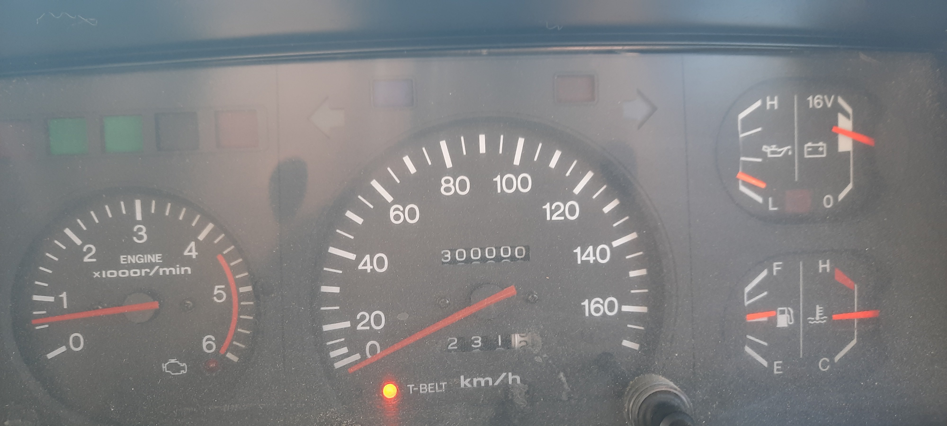
Also got past a mile stone just before the haka
4 points
-
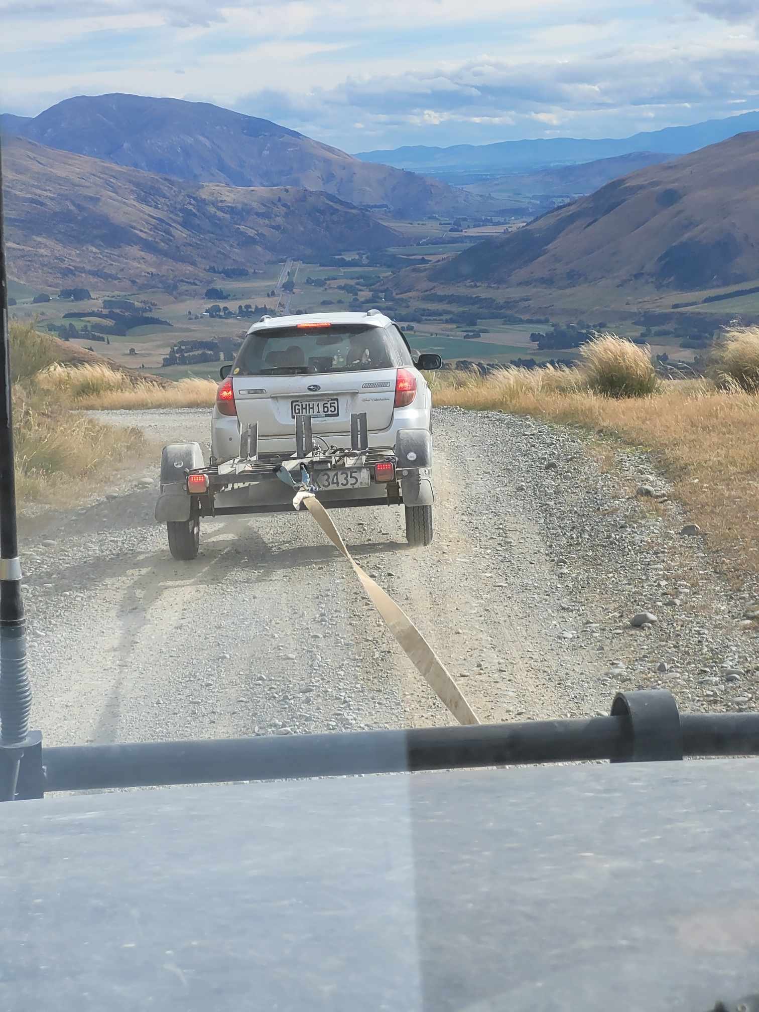
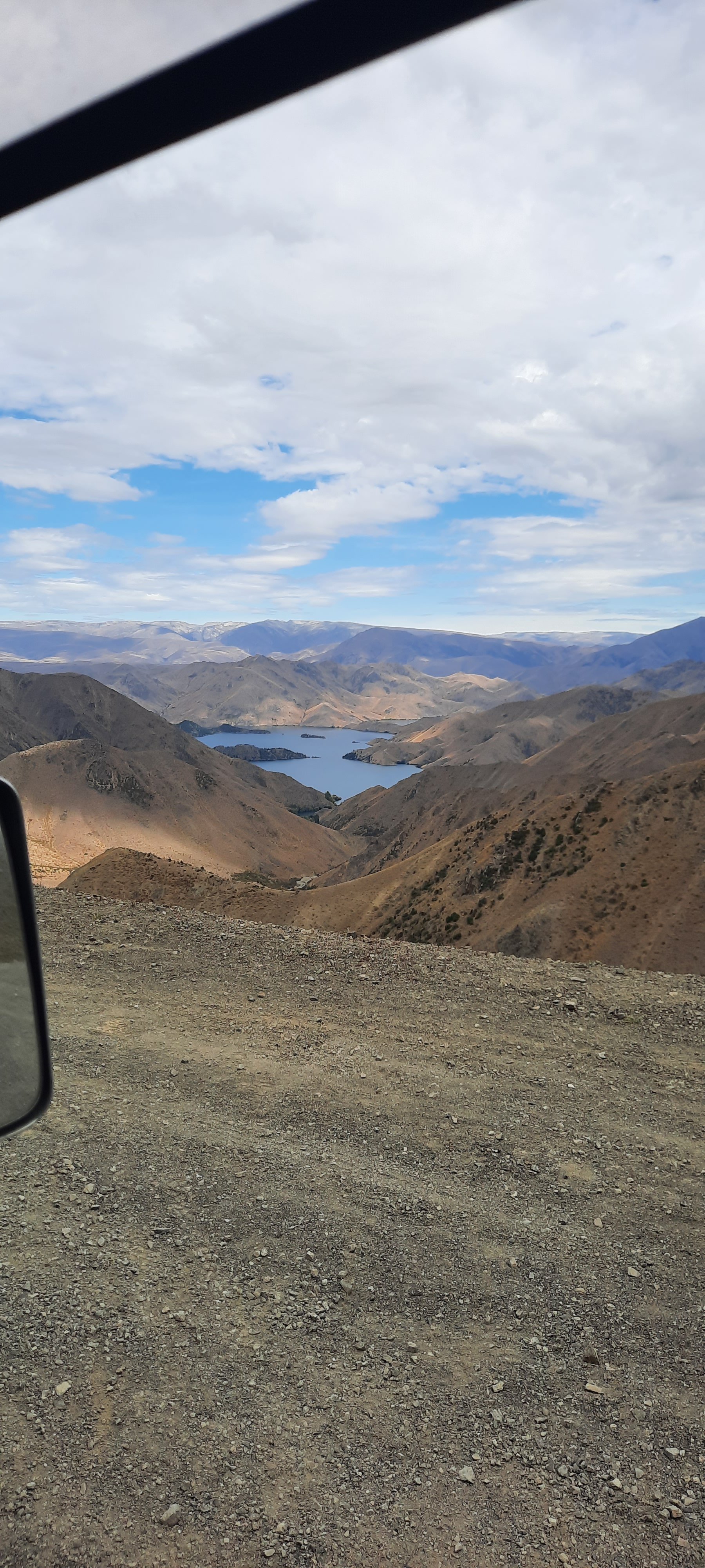
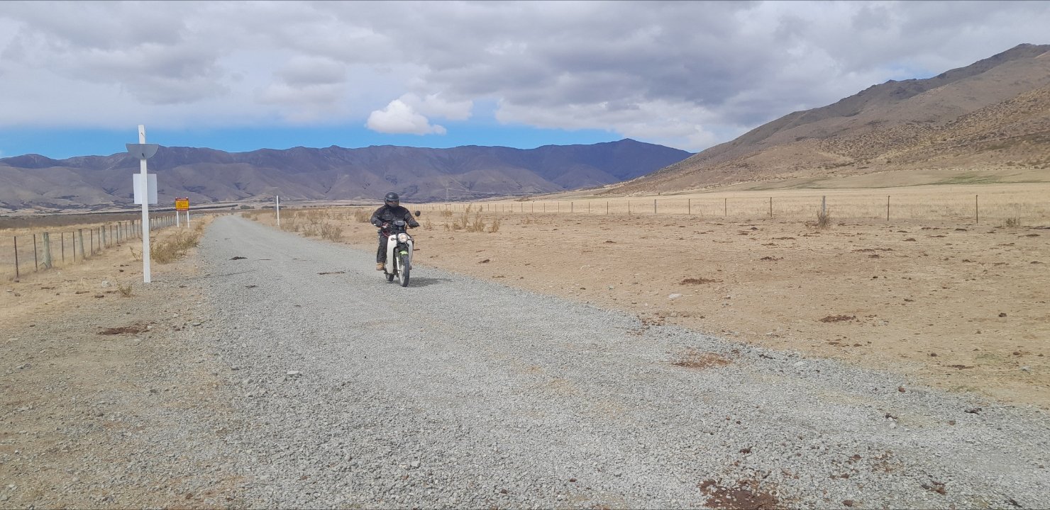
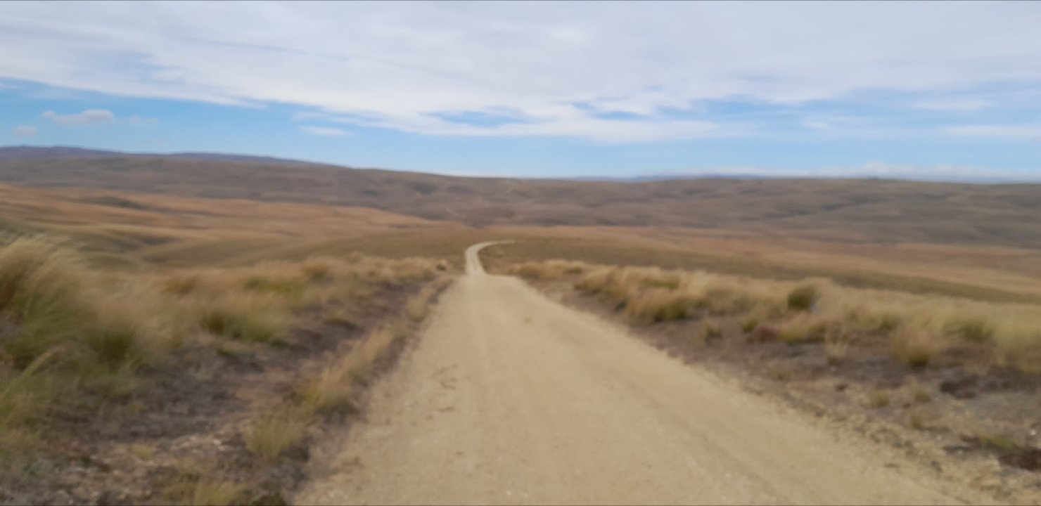
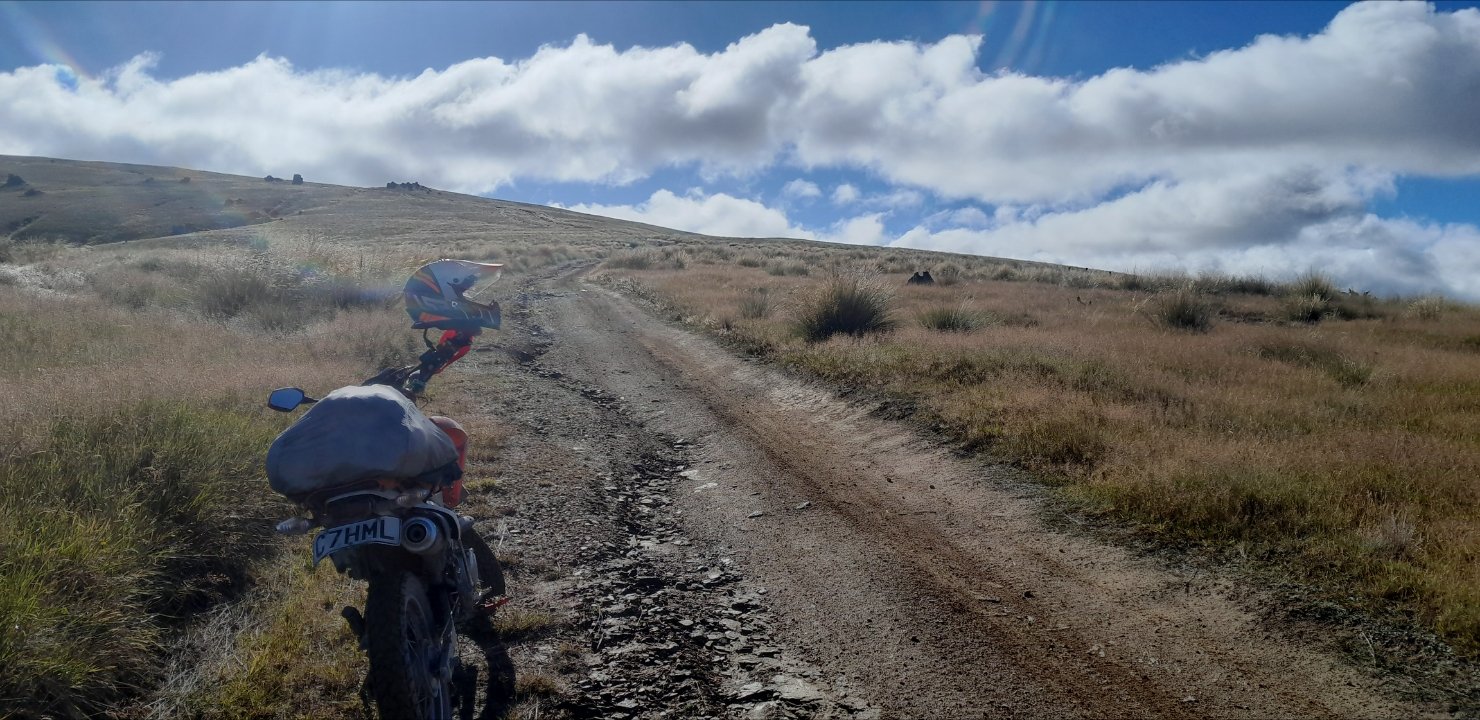
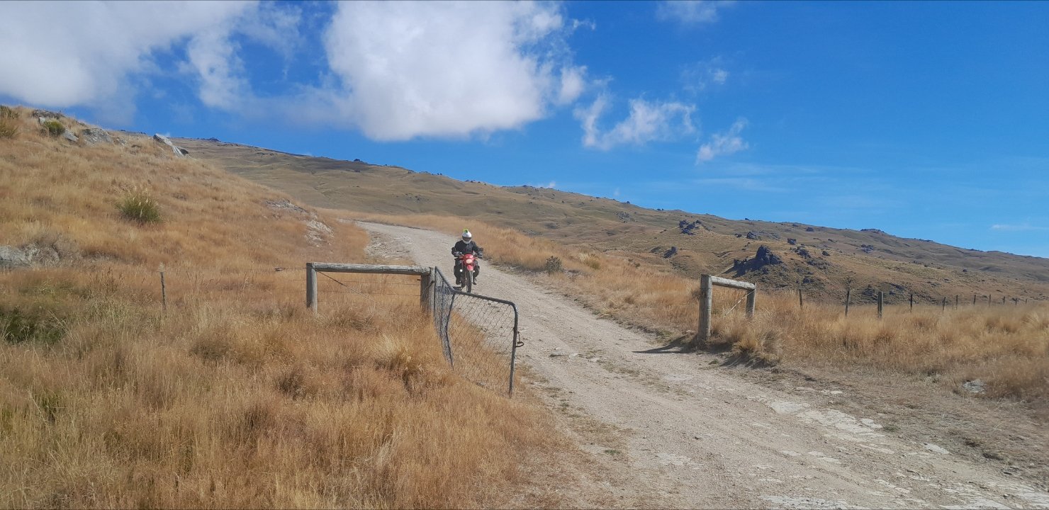
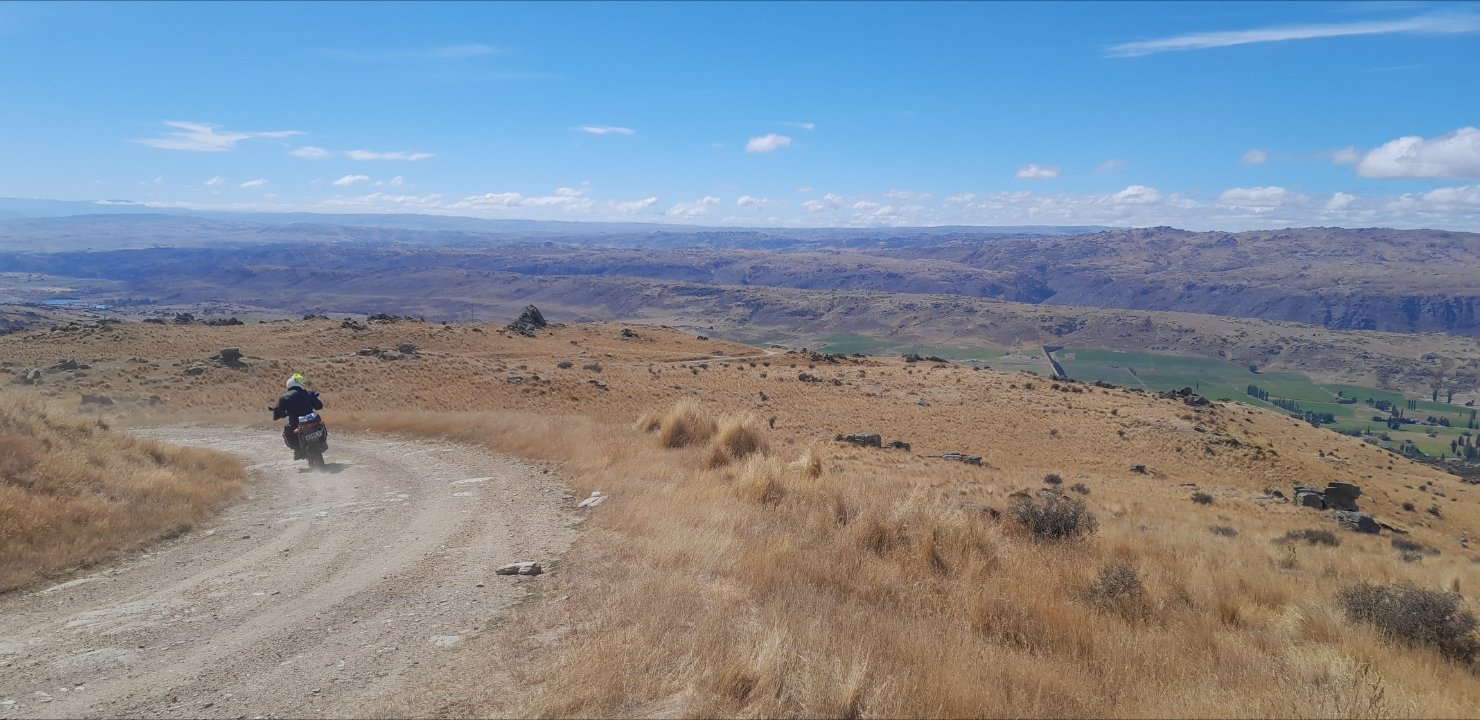
Going up the hill going down the hill
4 points
-
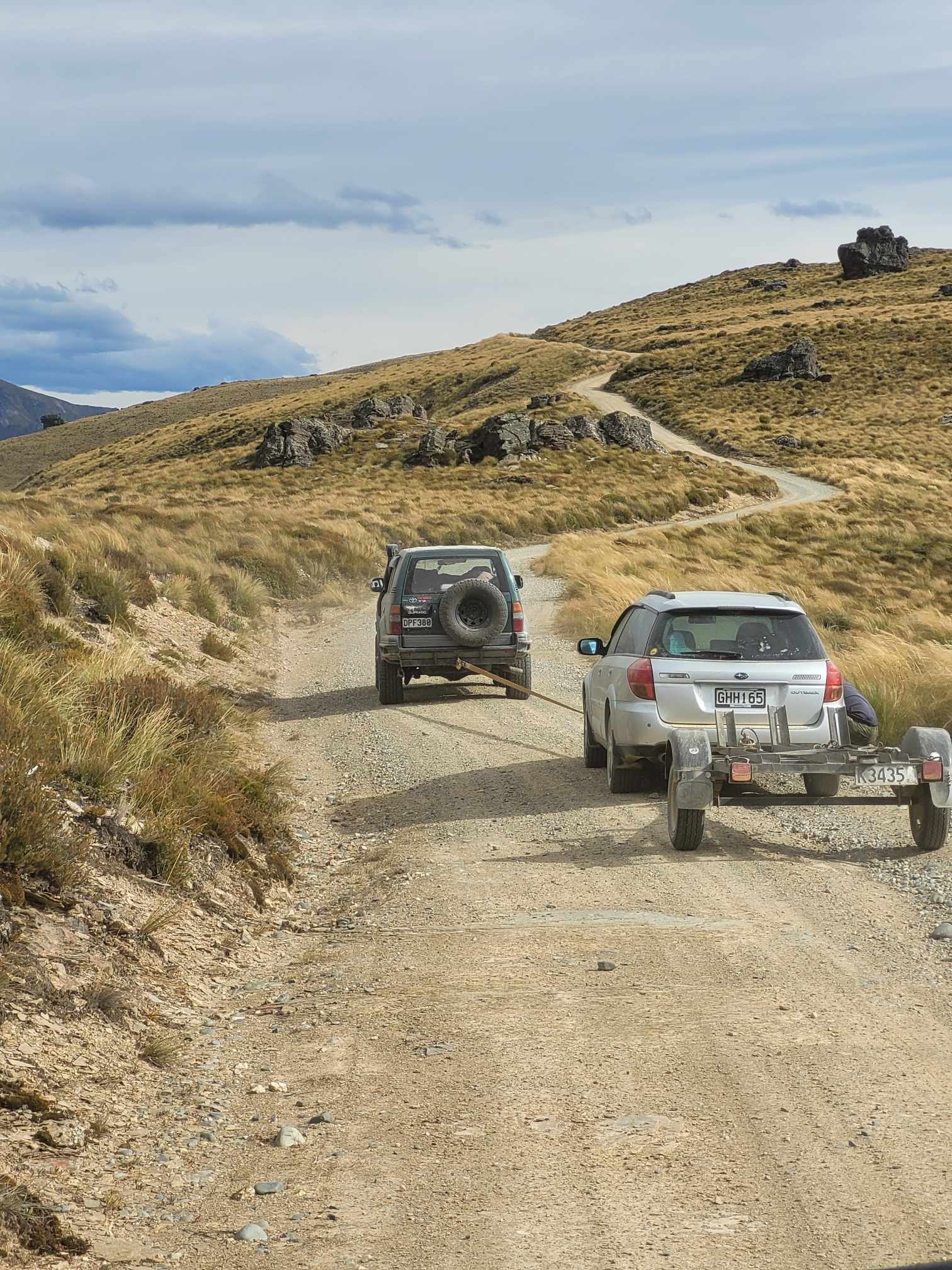
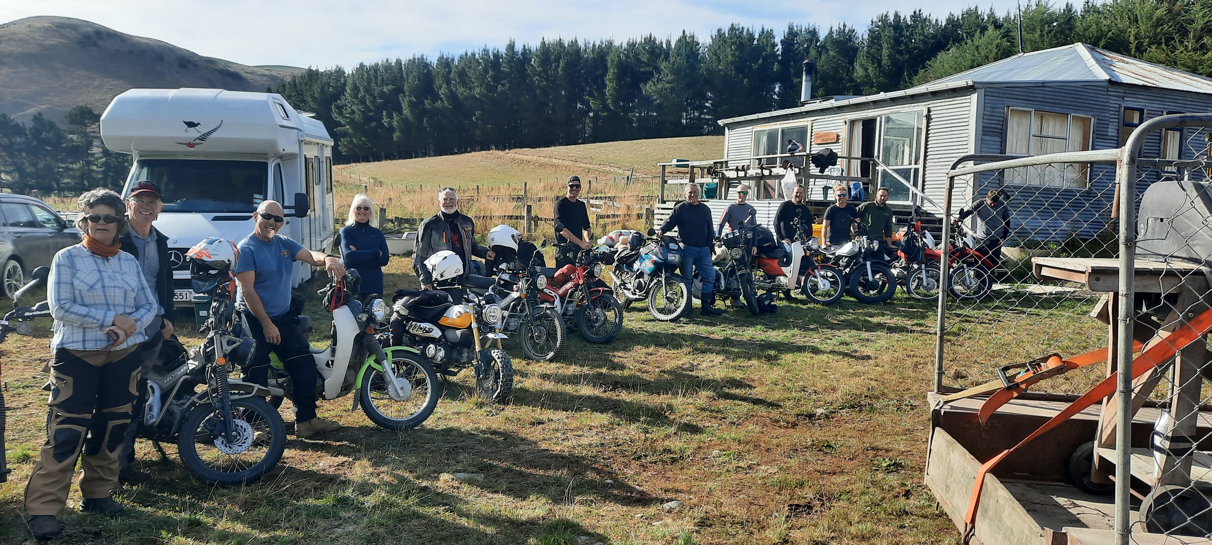
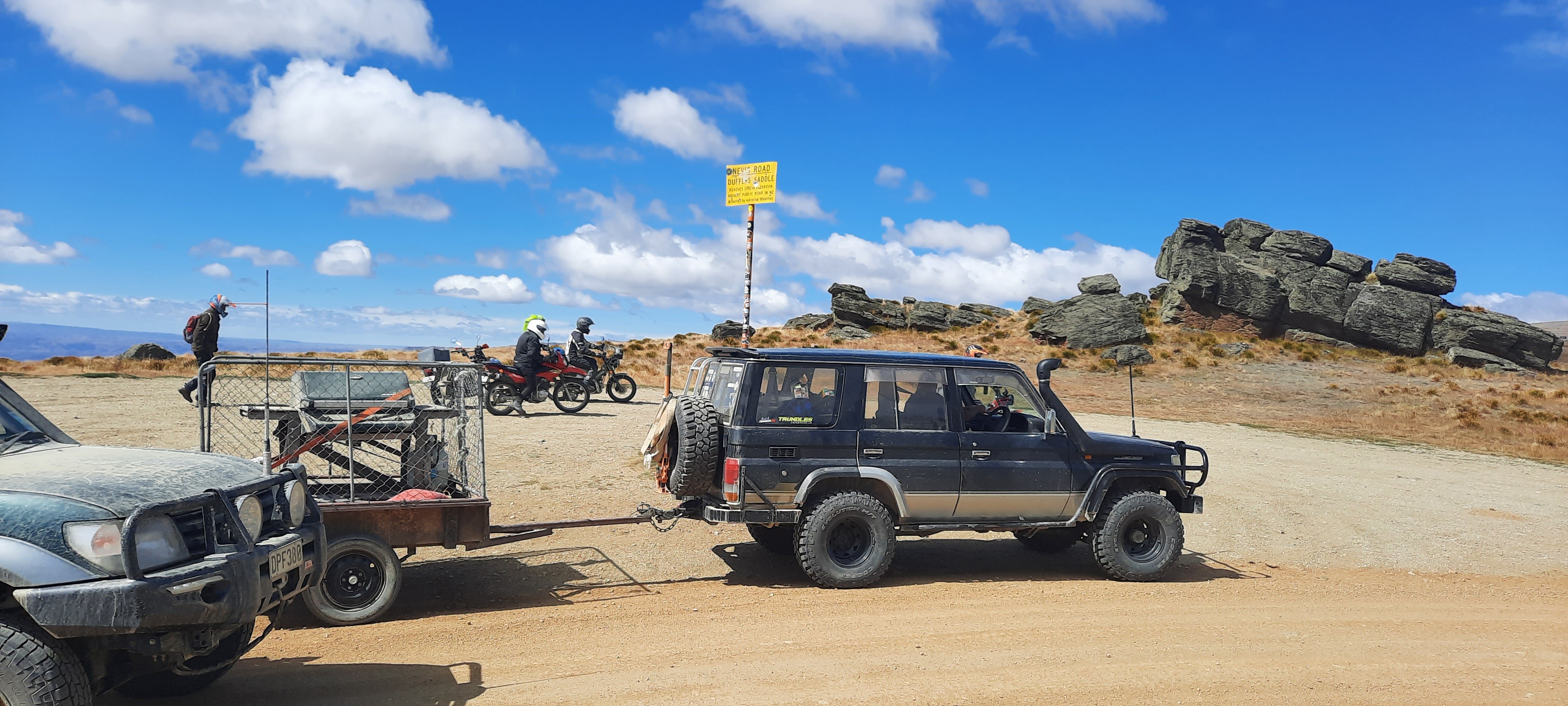
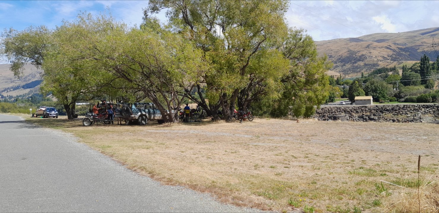
The big fruit with the big fruit Nevis crossing on the Yamaha Big Wang 200 Somewhere on the Nevis, having a few man coffees and mystery meat tubes End of Nevis. Support wagon still a while away saving a Subaru Outback that took a drink in a bog Maggot sack set up in exact dogging GPS coordinates4 points
-
holy birthday cake batman, that was epic. gutted i couldnt get my shit together for the full hog, but even 2 days was enough to fizz the bung real hard. massive thanks to the support crew, Mof and his great organisation and leadership skills, and all the riders for being absolute GCs. was such an awesome crew good yarns good vibes. will post some pics up soon. was trying to take as many as i could but was too busy cheesing, a go pro is a must next year. Highlights in no particular order: Bart and the two hole turkey roast machine, see you round like a jaffa, using a subaru outback as a sledge reverse towing down the nevis hill, double browns in picturesque locations, jugs of speights, roadside gourmet bb grillers, Pet Shop Boys at 11pm at piano flat campsite, old man range rock steps, large phallic shaped rock on windy hill, damside snags. Basically you just suck if you didnt go4 points
-
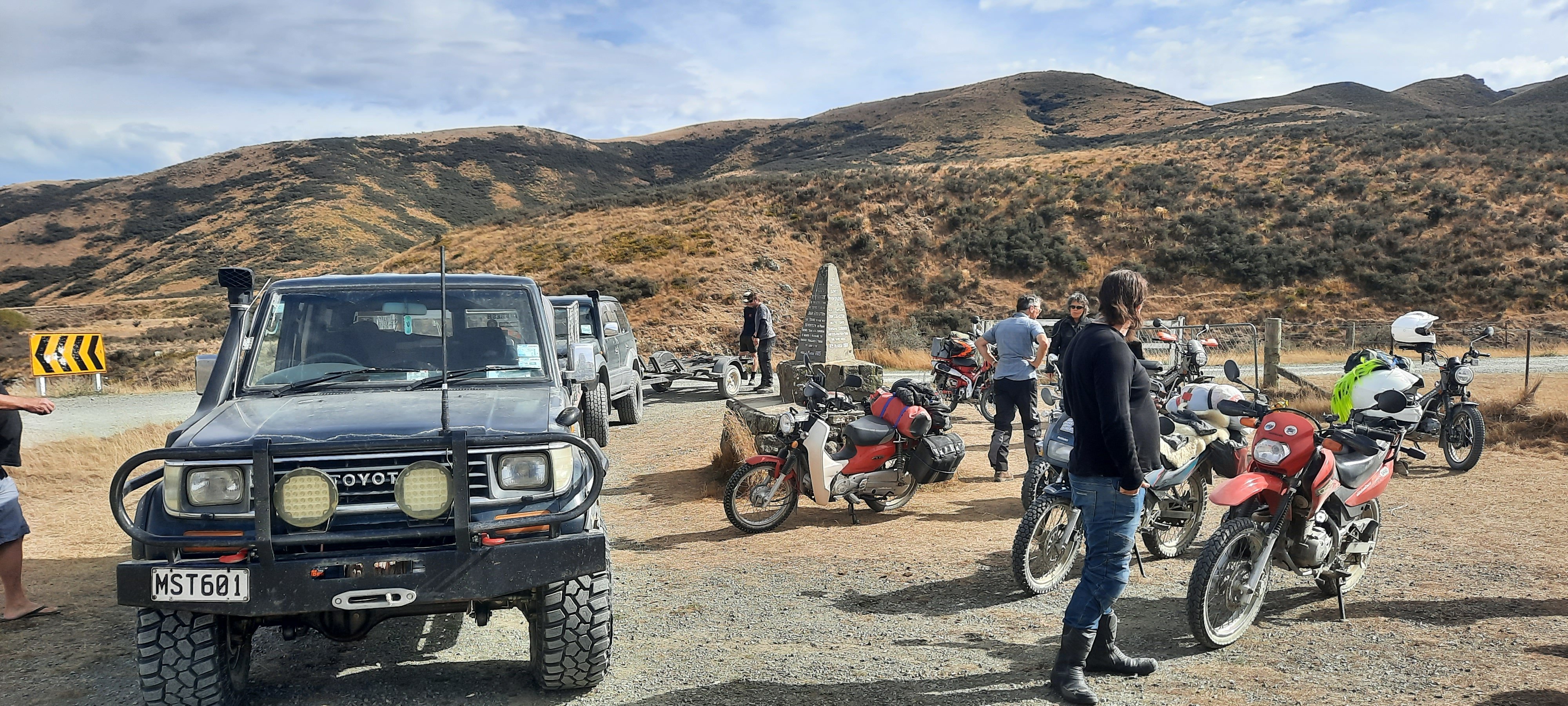
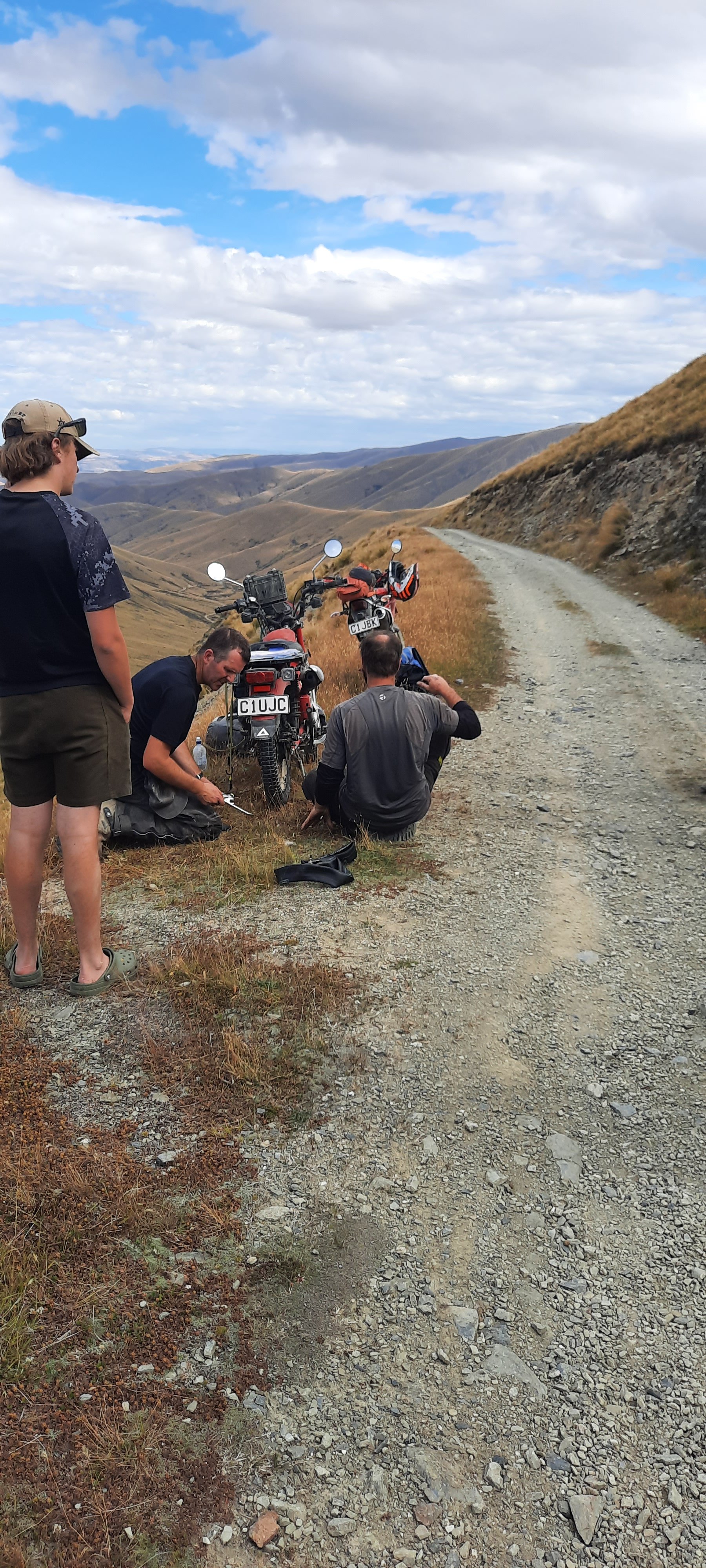
Fuck, this ride has been epic! Bbqs, beers, and small bikes. Plus pub feeds. Nothing short of a pleasure to have @TimShadboltfan27 joing us for part of the journey. Also quite delightful to get to see @Truenotchfor a beer and a sharn at the riversdale pub last night. Thus far the weather has co-operated. And we've had nobody injured/very low boke attrition rate. (Besides @holdenman cable, @NZChaddy has suffered two snakebite flatties. I wish this ride could never end.......4 points
-
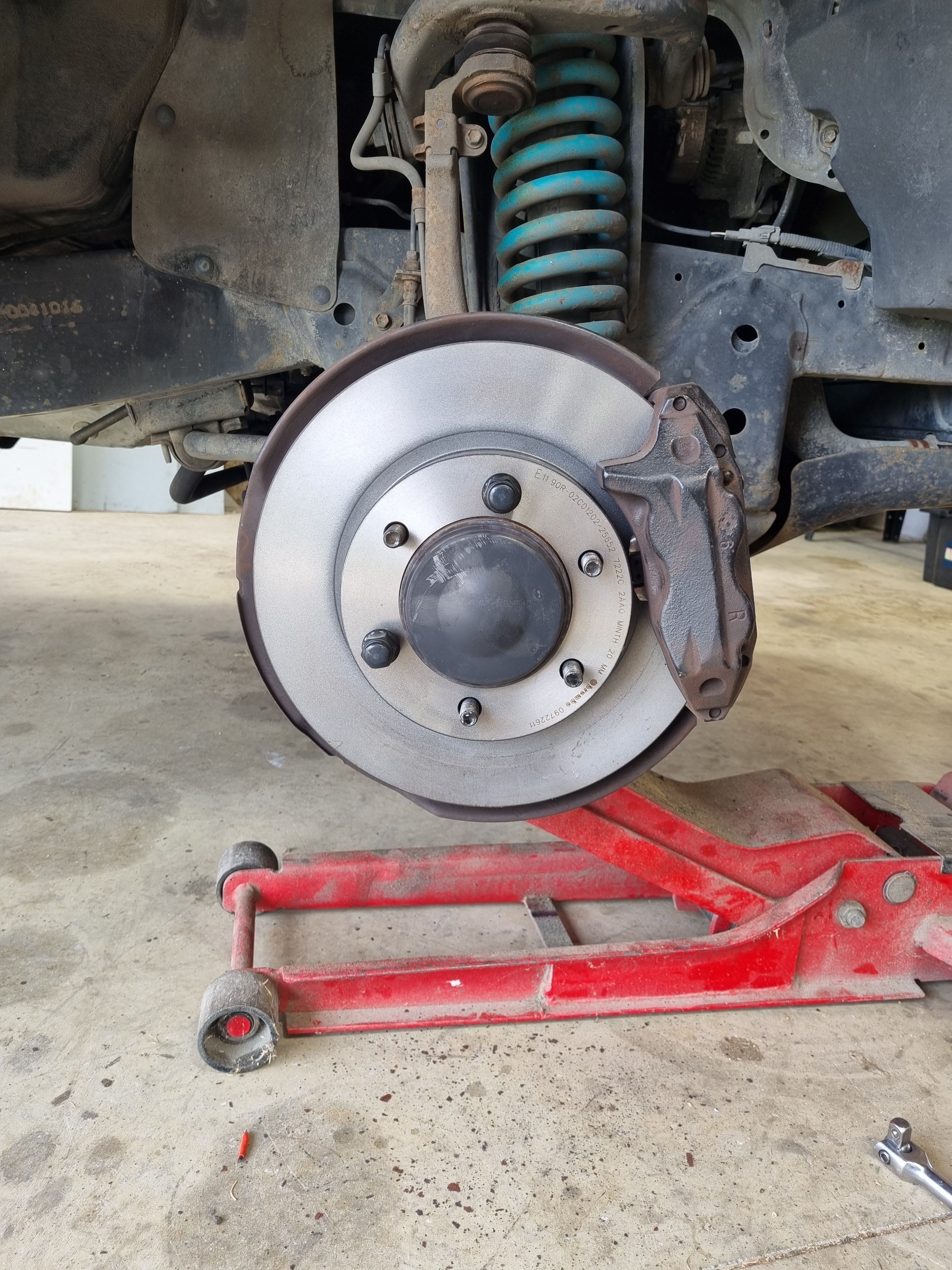
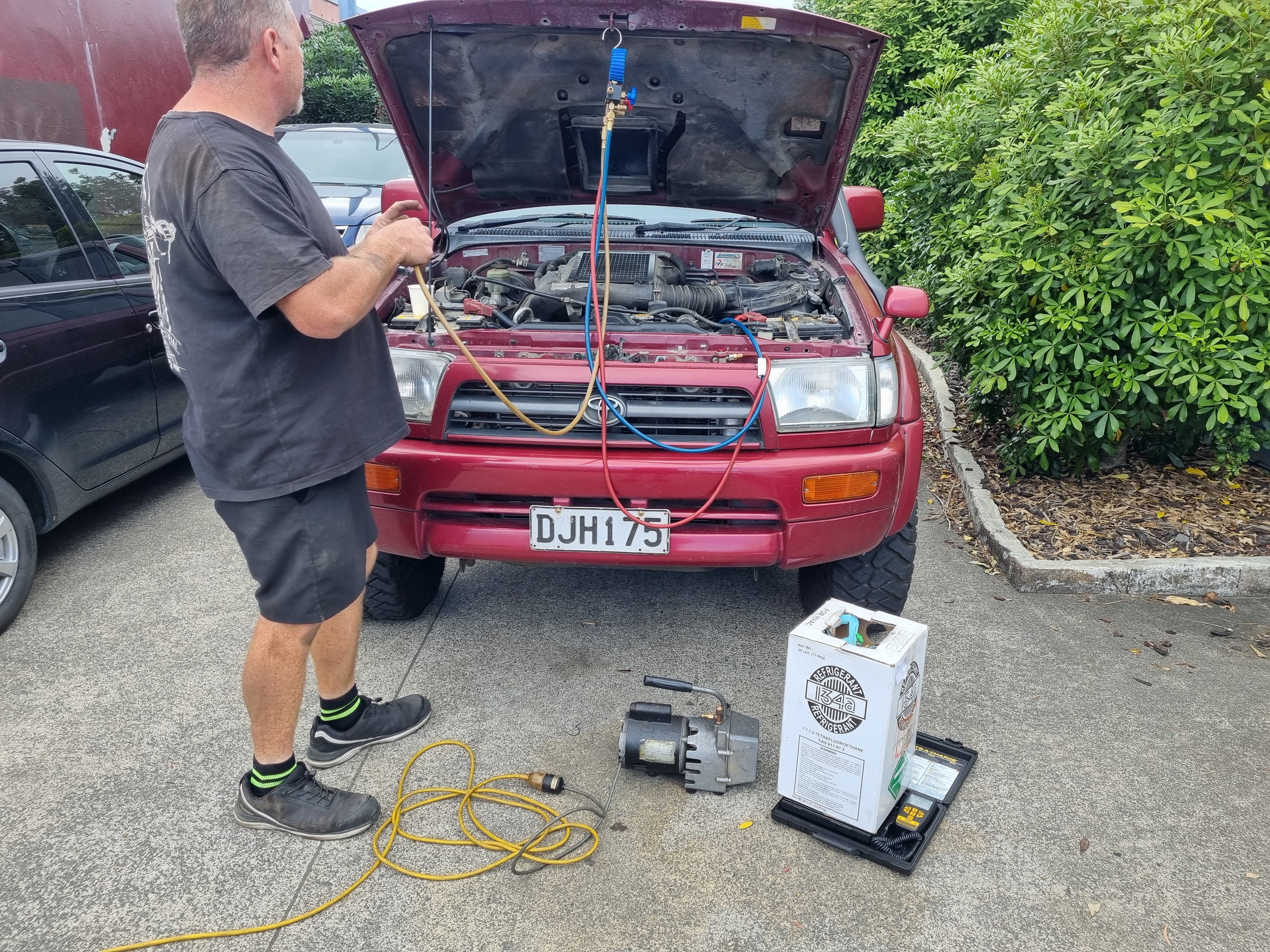
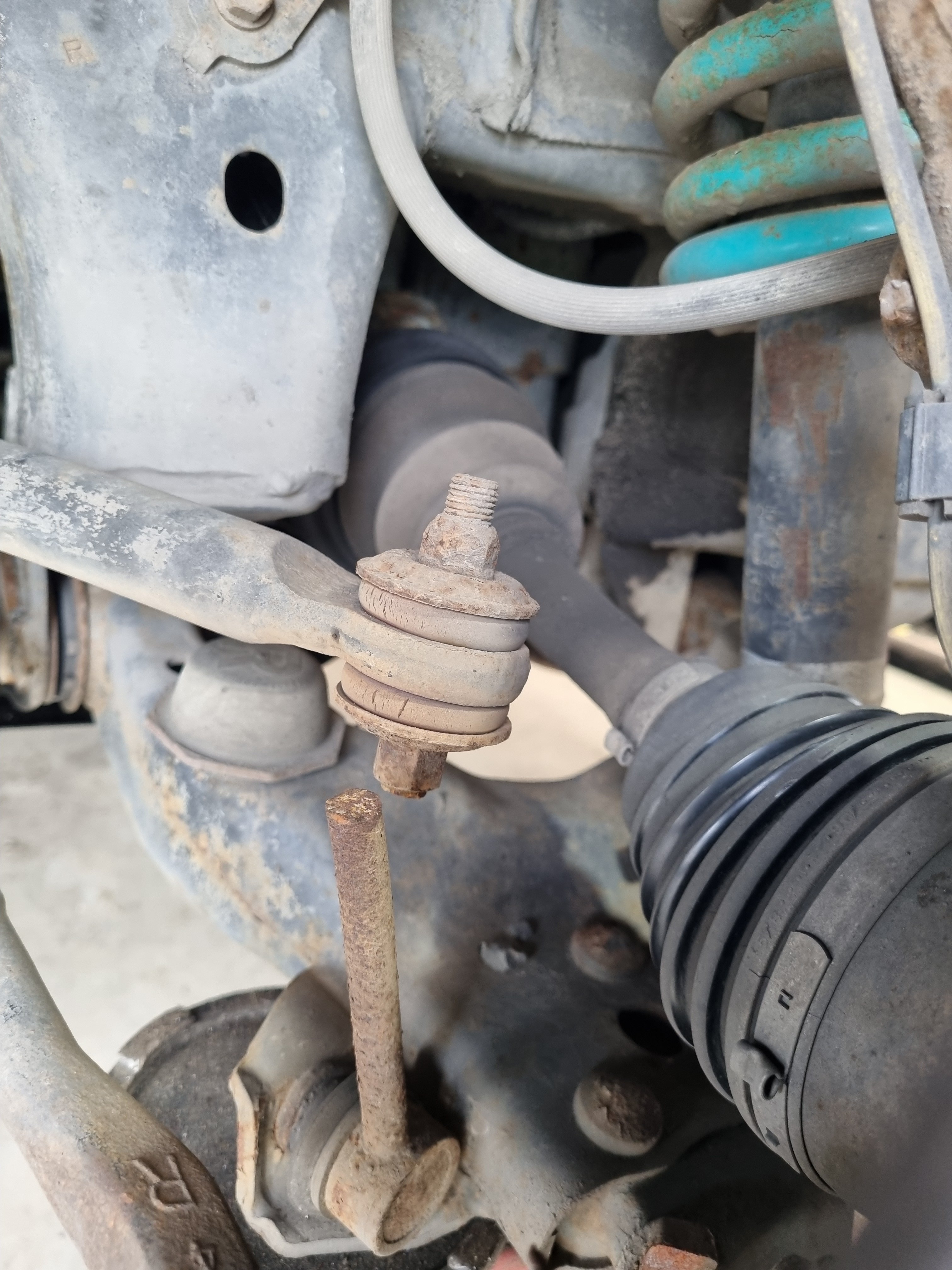
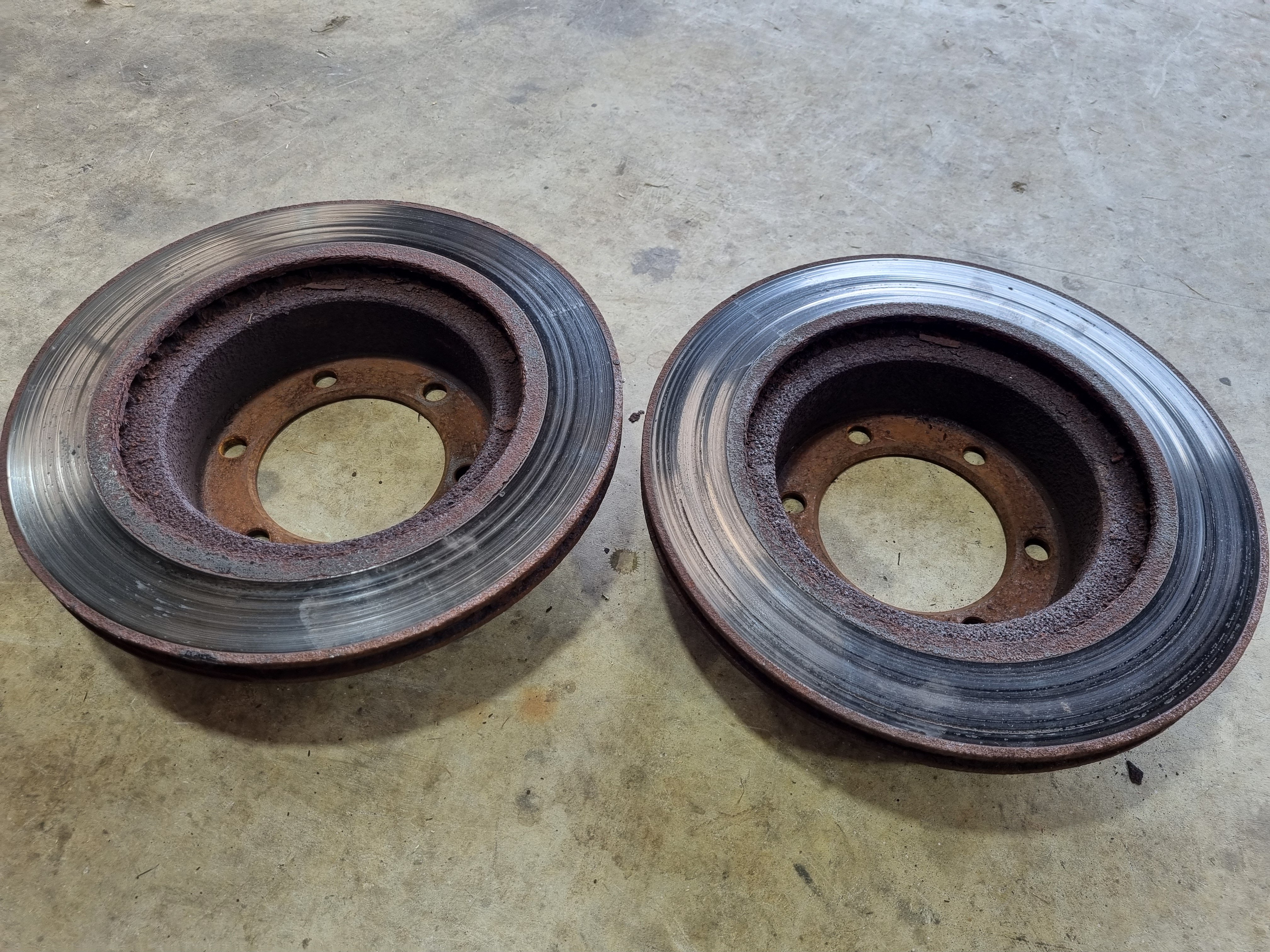
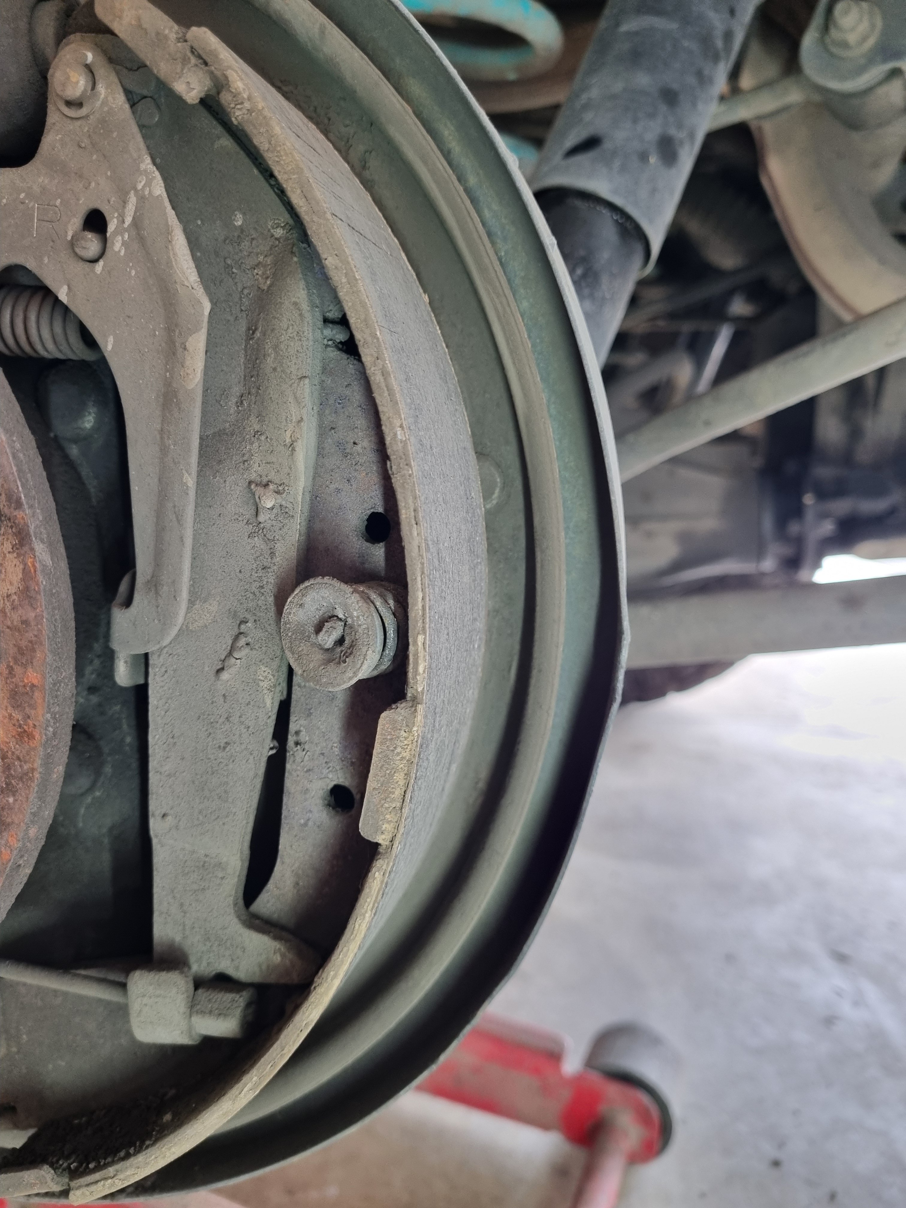
Nick recharged the AC system and now it works fucking ace. Couldn't feel my fingers by the time I got home so I'm calling that a win. Installation of new discs and drums. Front was easy, as you'd expect. Rear was a bit bit difficult to get the drum of due to the massive lip on the inside. However once I got the drum off I discovered the thinnest brake shoe I've ever seen. And of course the wheel cylinder was leaking so I'll get new bits next week and re- do the whole back brakes. Also I found the reason why I'm now the best 4wd driver in NZ. Auto disconnected sway bar for max flex bro. That's what the 4wd people say, you wouldn't understand.
4 points
-
3 points
-
3 points
-
3 points
-
3 points
-
3 points
-
3 points
-
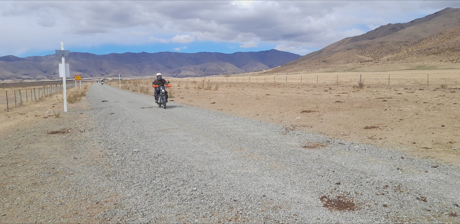
Moist morning mildew madness. piano flat was turbo lush. it begins!!!! me oh my i have enjoyed that yes boy Waiting for sumpson after he took a lie down wrestling the NBC through the ruts Adrian pickin the cleanest line through the worst bog3 points
-
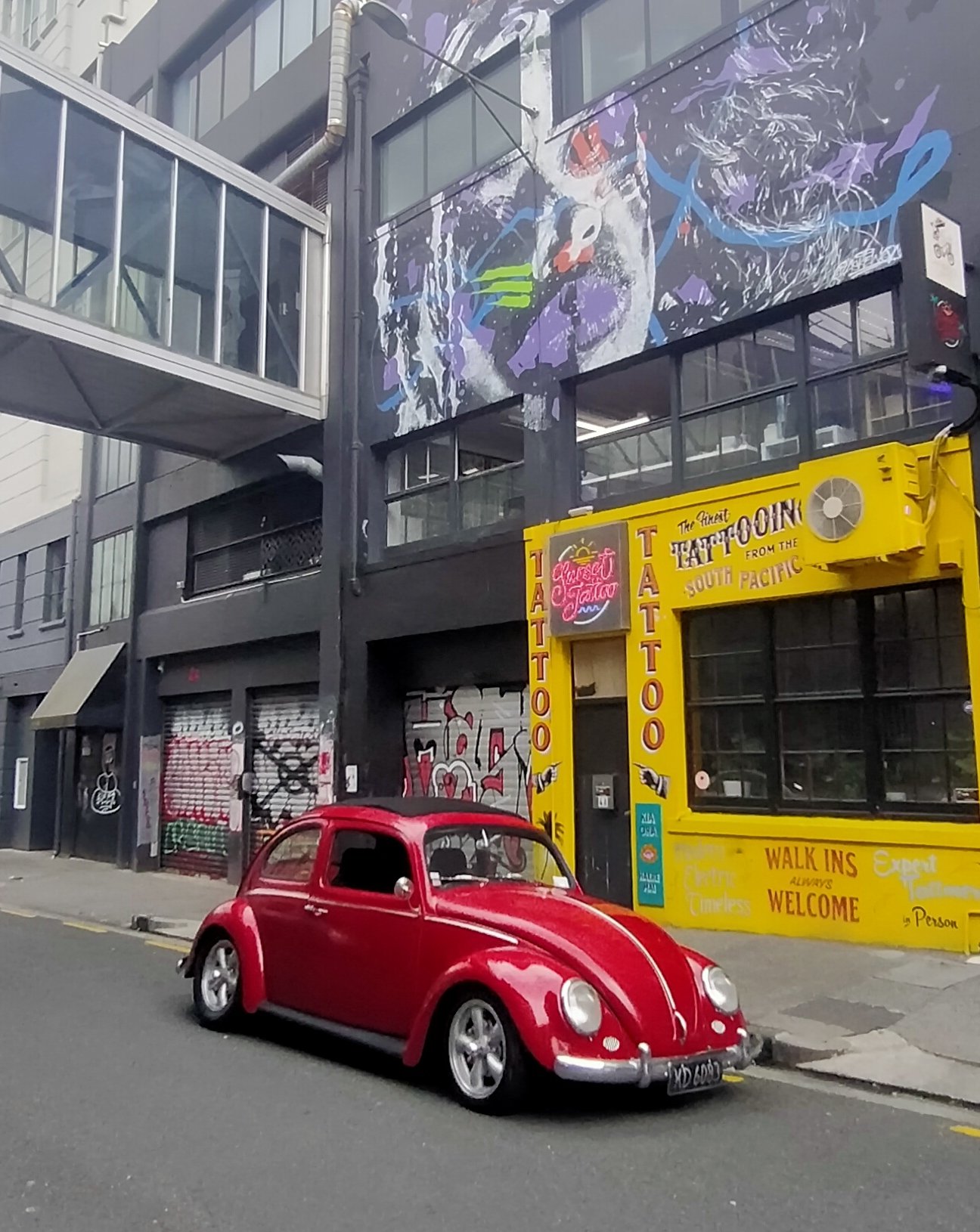
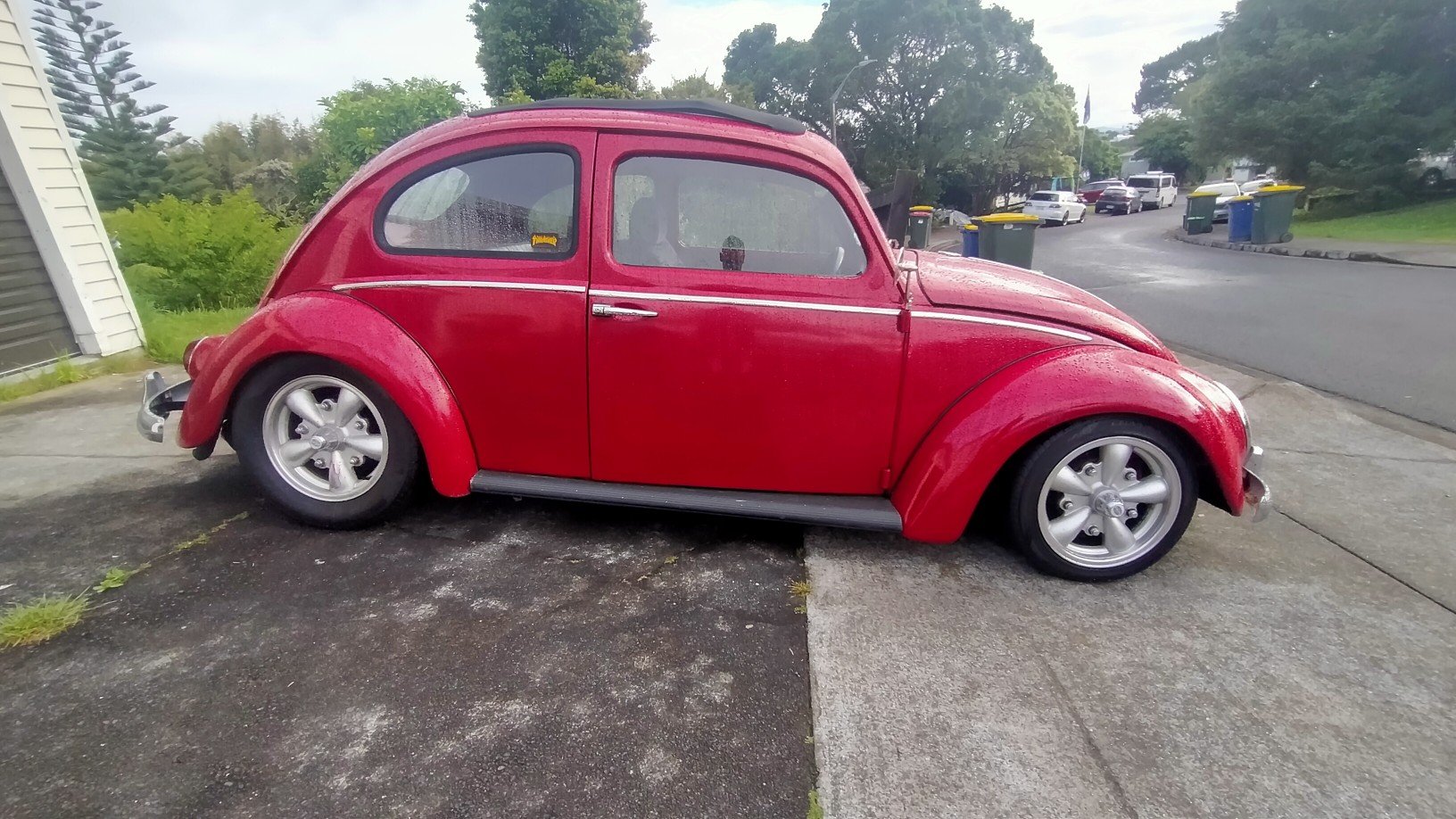
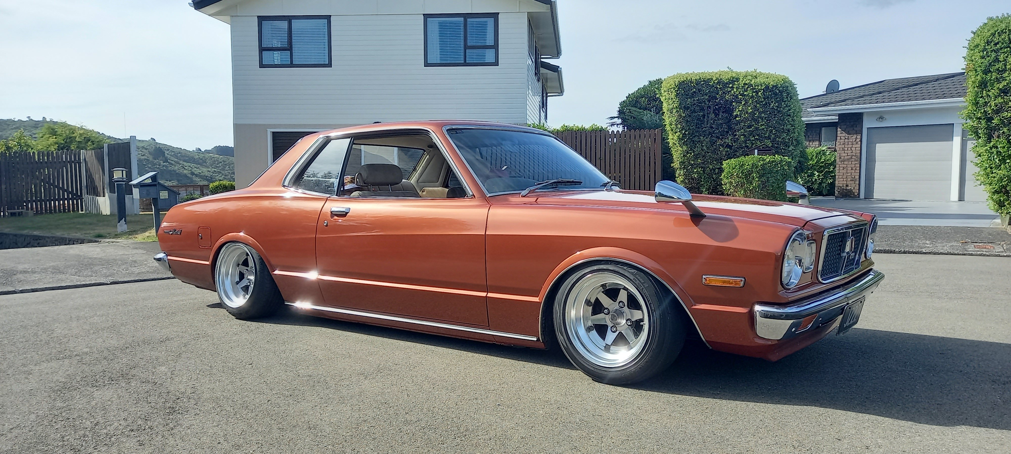
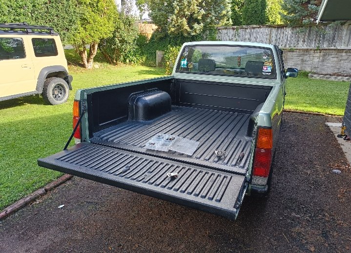
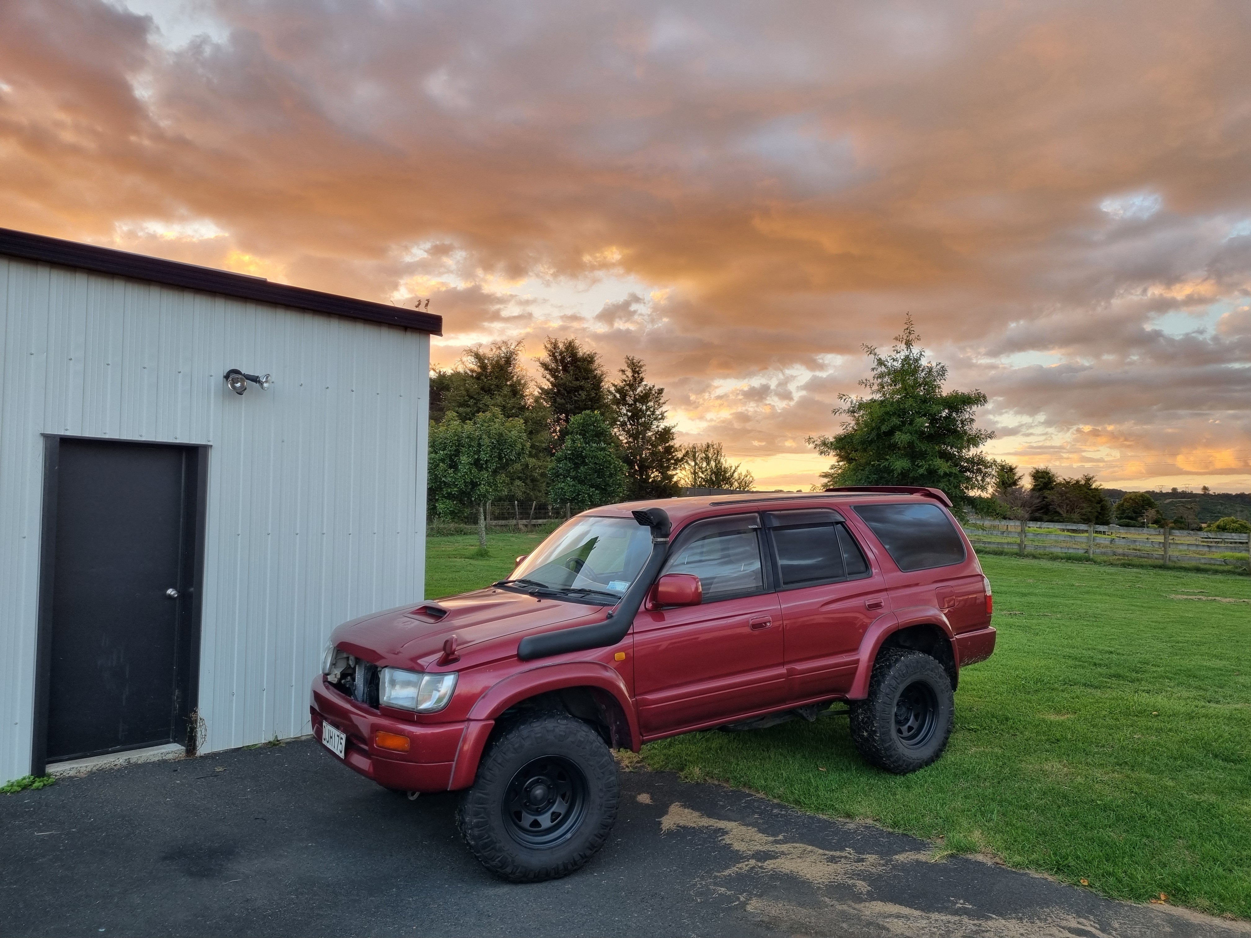
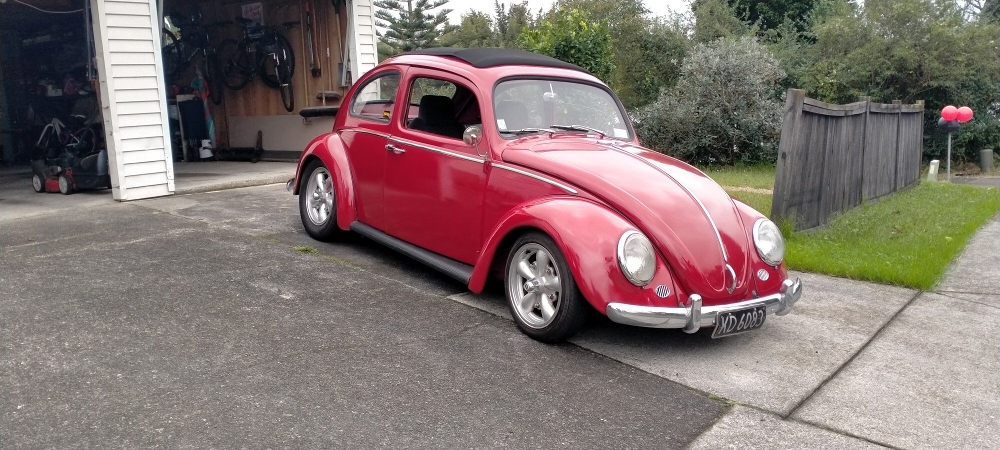
Chuffed how it came out. It's not a show car paint job by any means but it's what I wanted. Still has some dents and dings as I wasn't paying for a full panel job haha. Needs lowering ASAP, have a spare set of leaves I need to do reset.
3 points
-
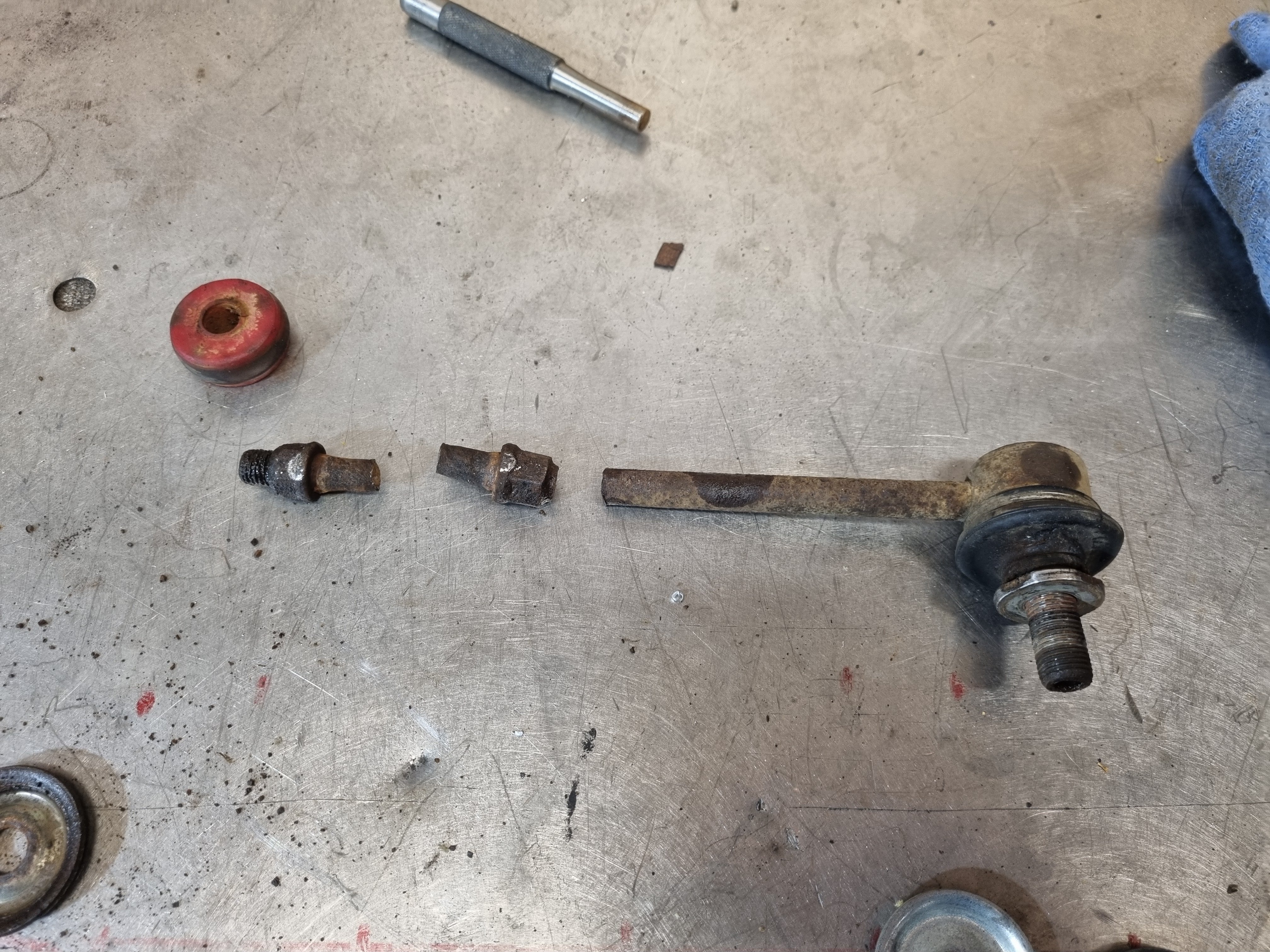
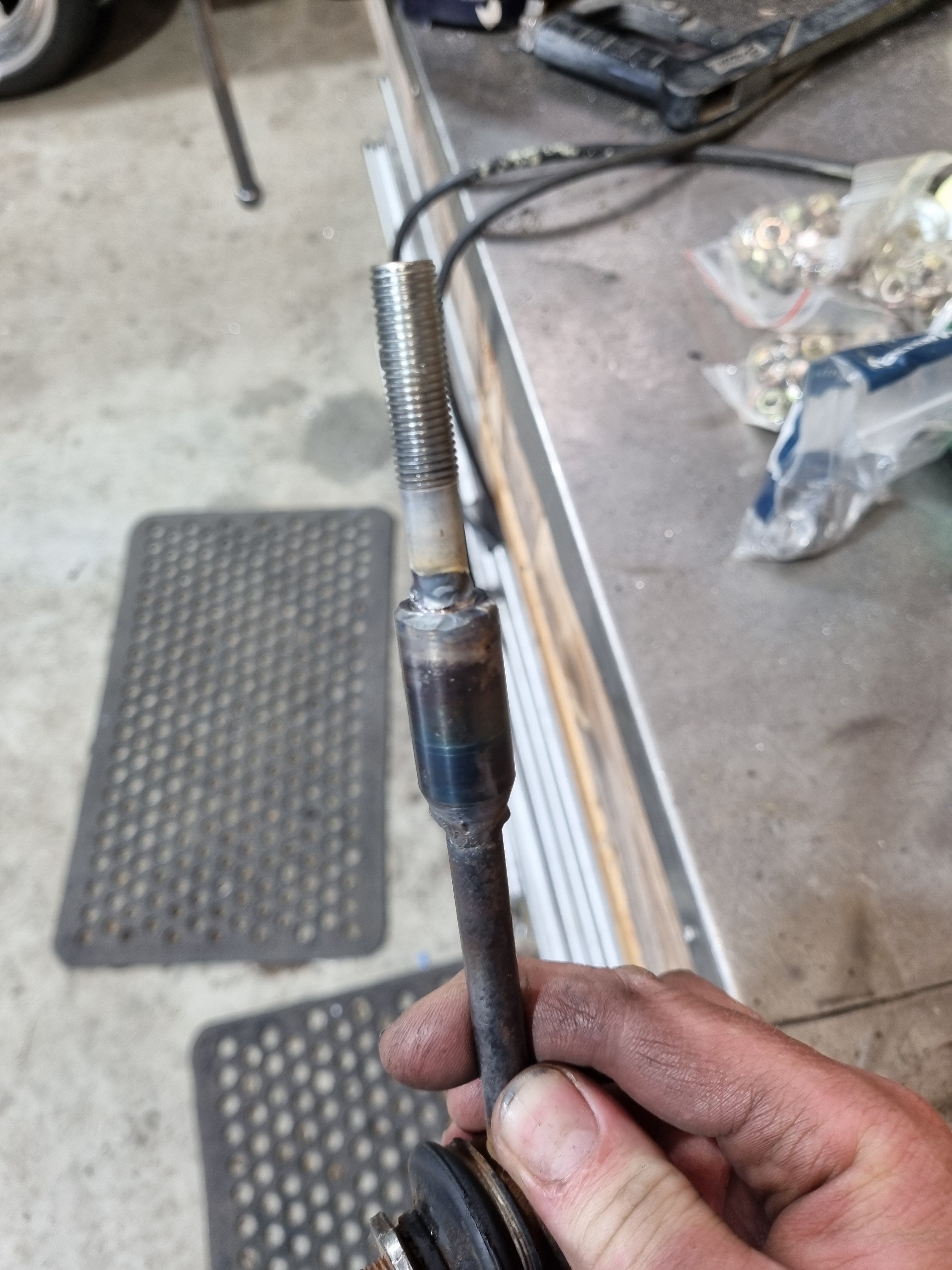
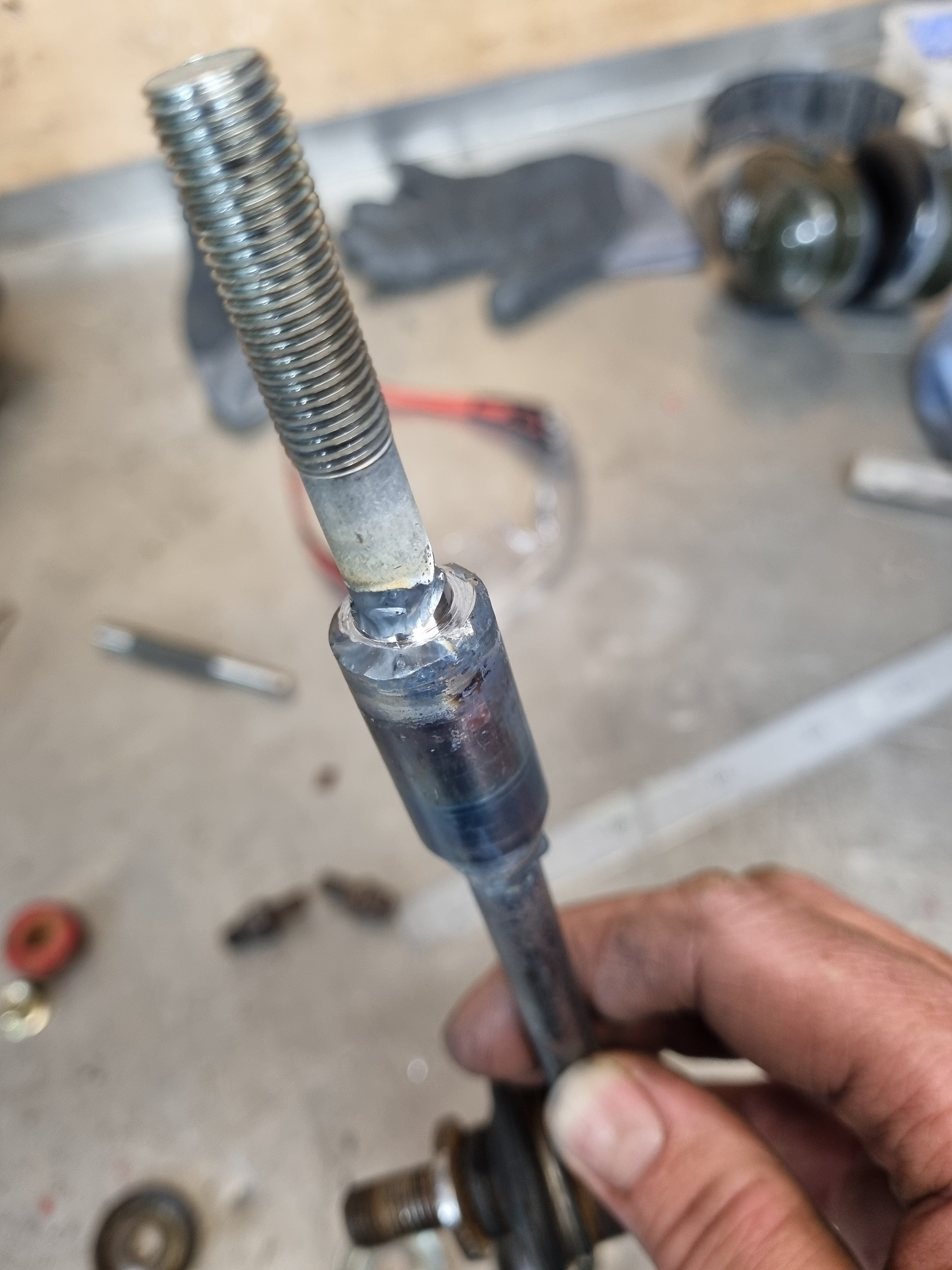
You're not going to believe this but the top bit of the swaybar link that wasn't broken broke when I tried to undo it. So I welded a new end on it.
3 points
-
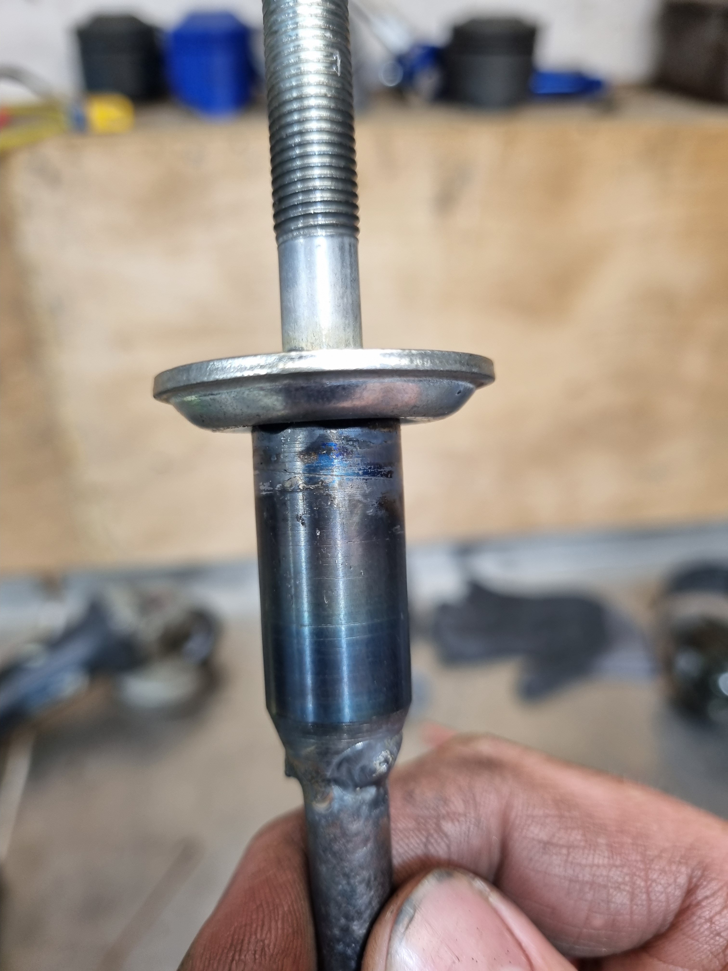
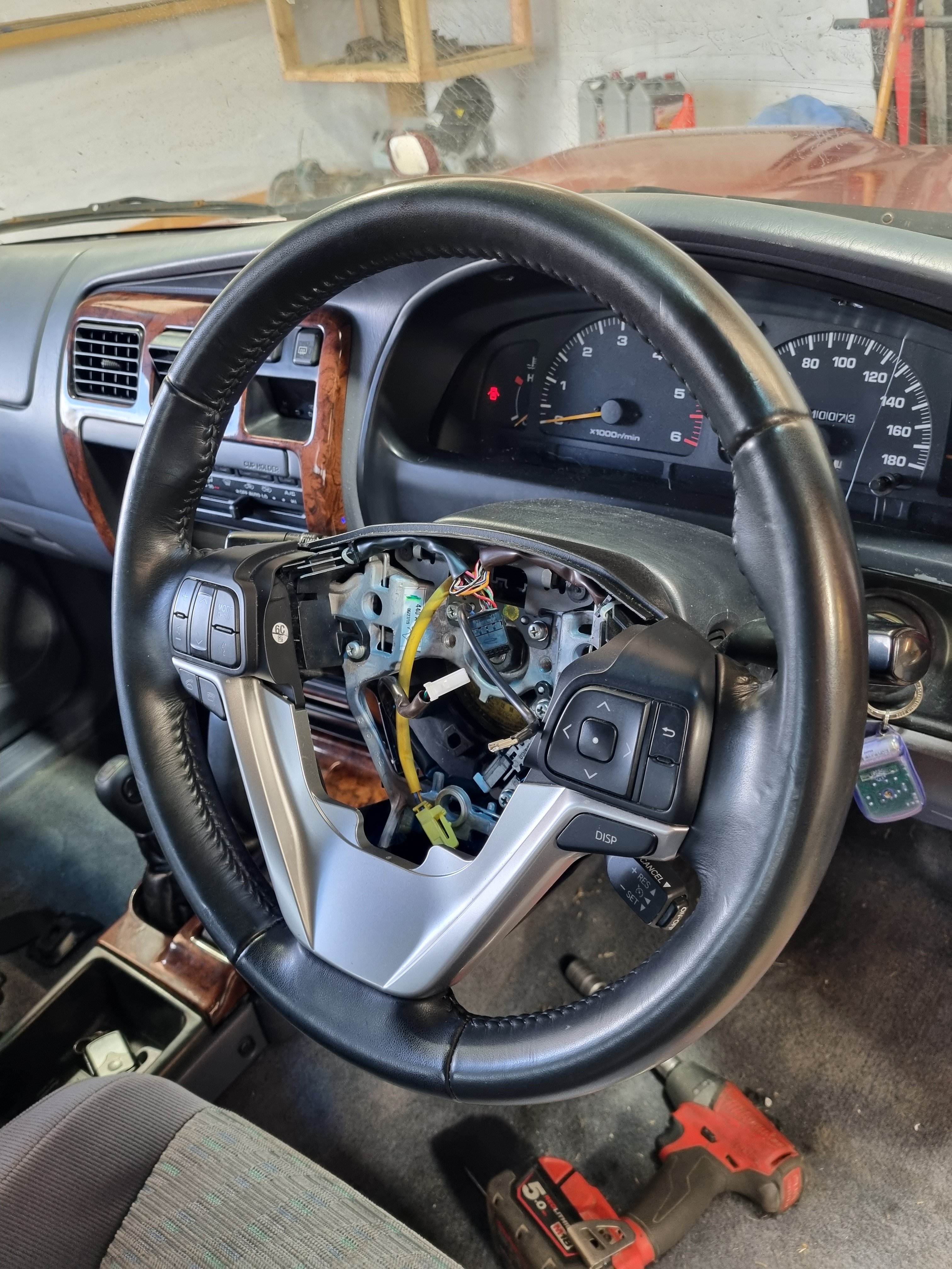
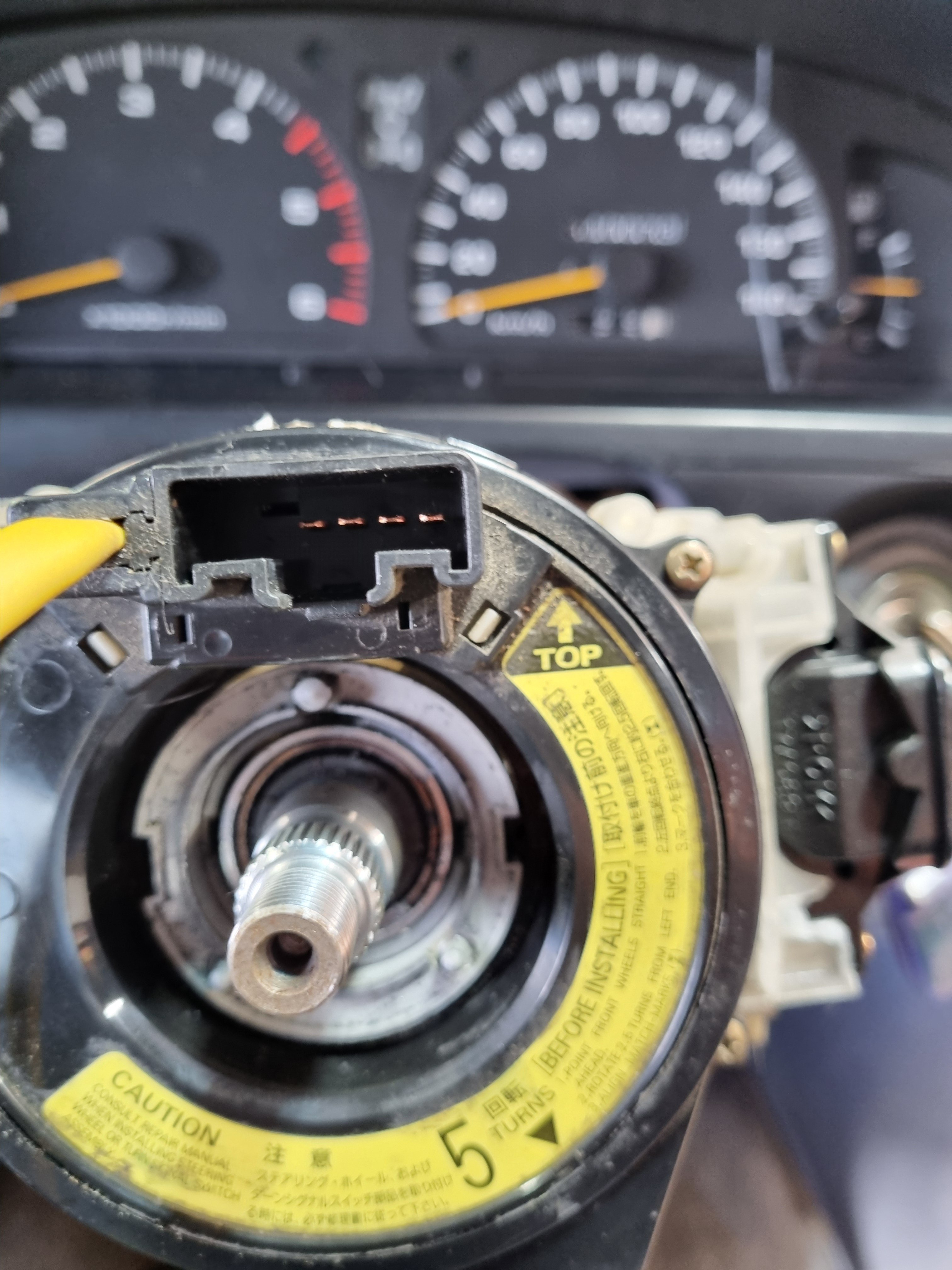
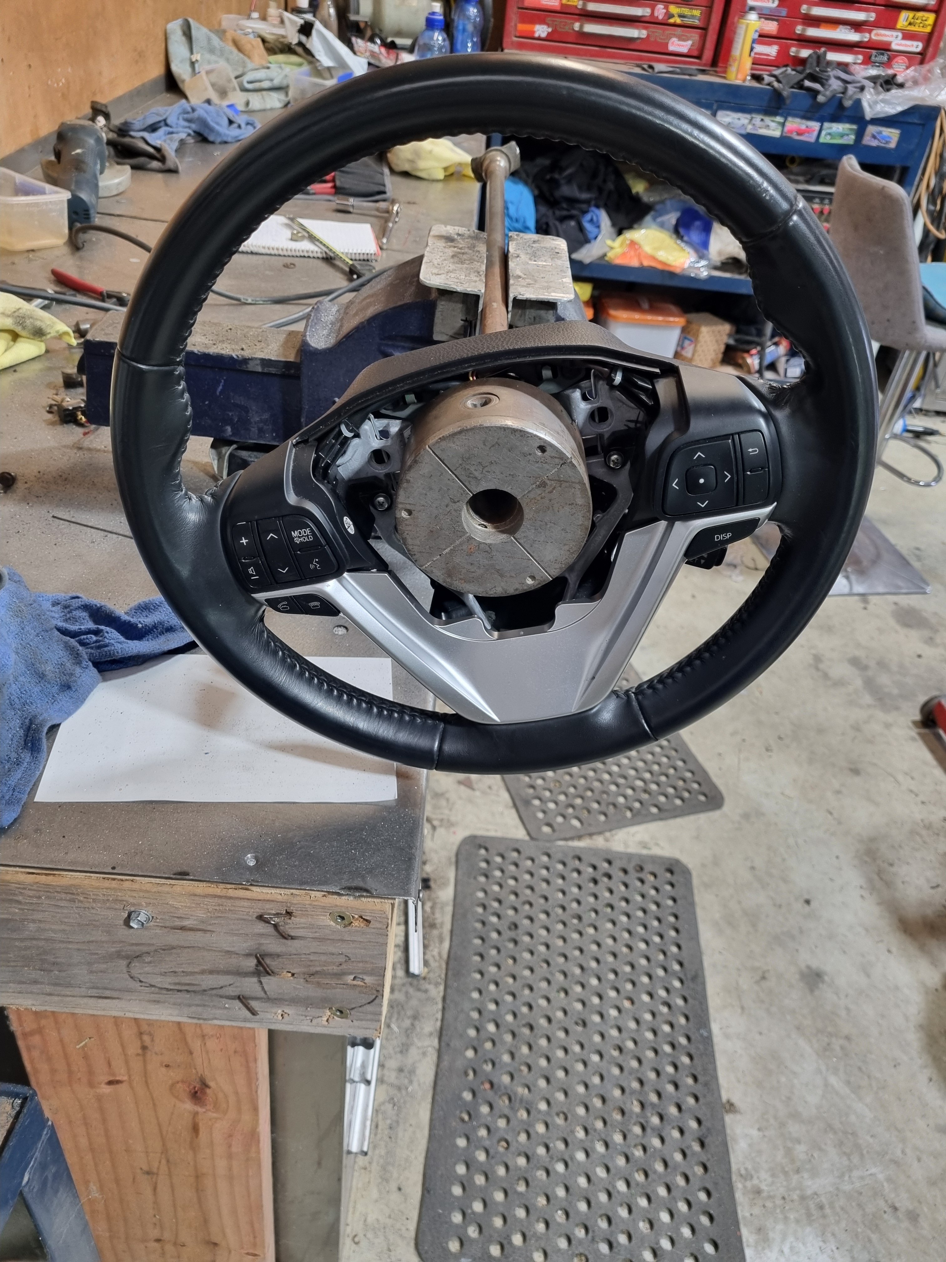
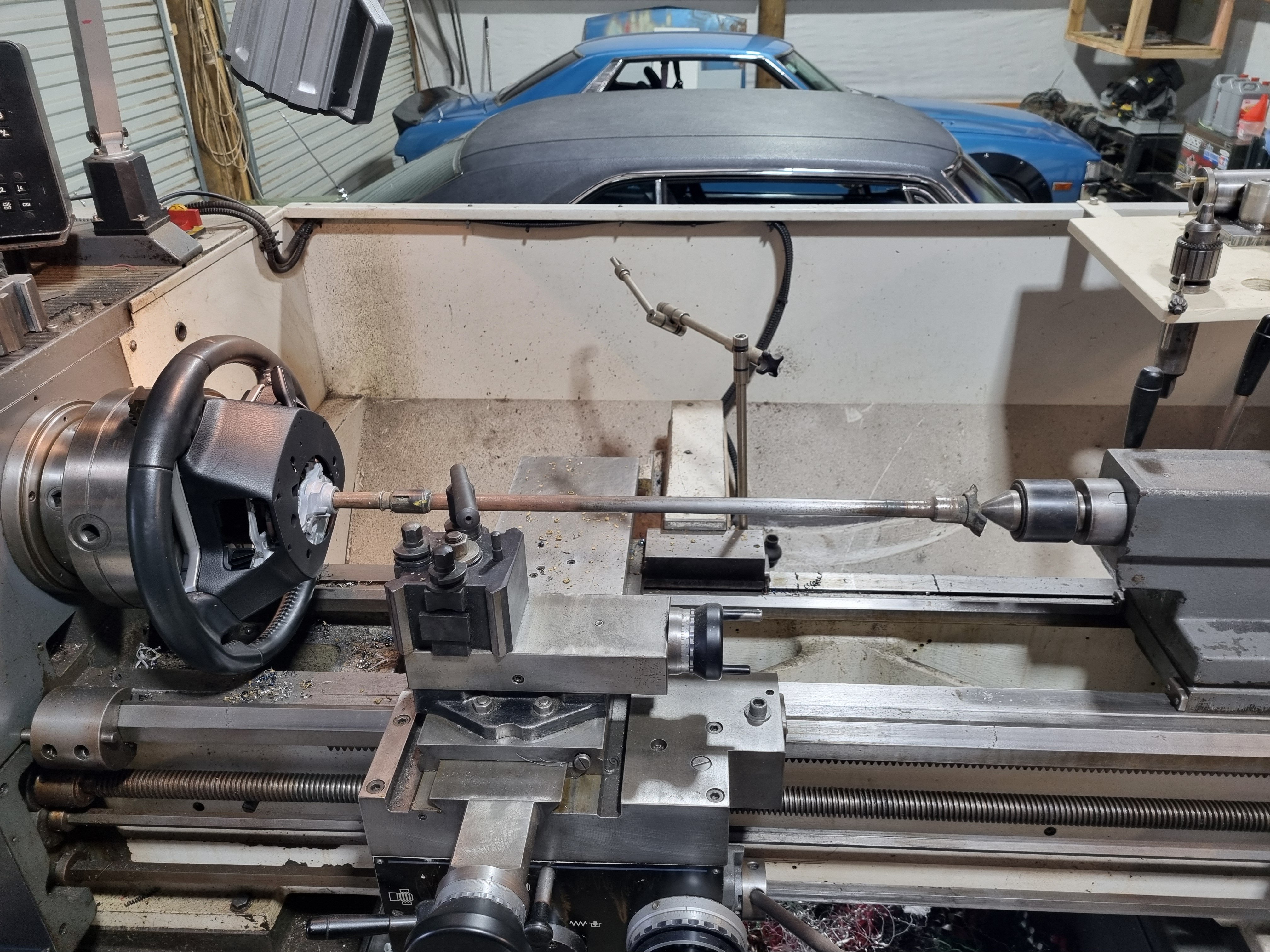
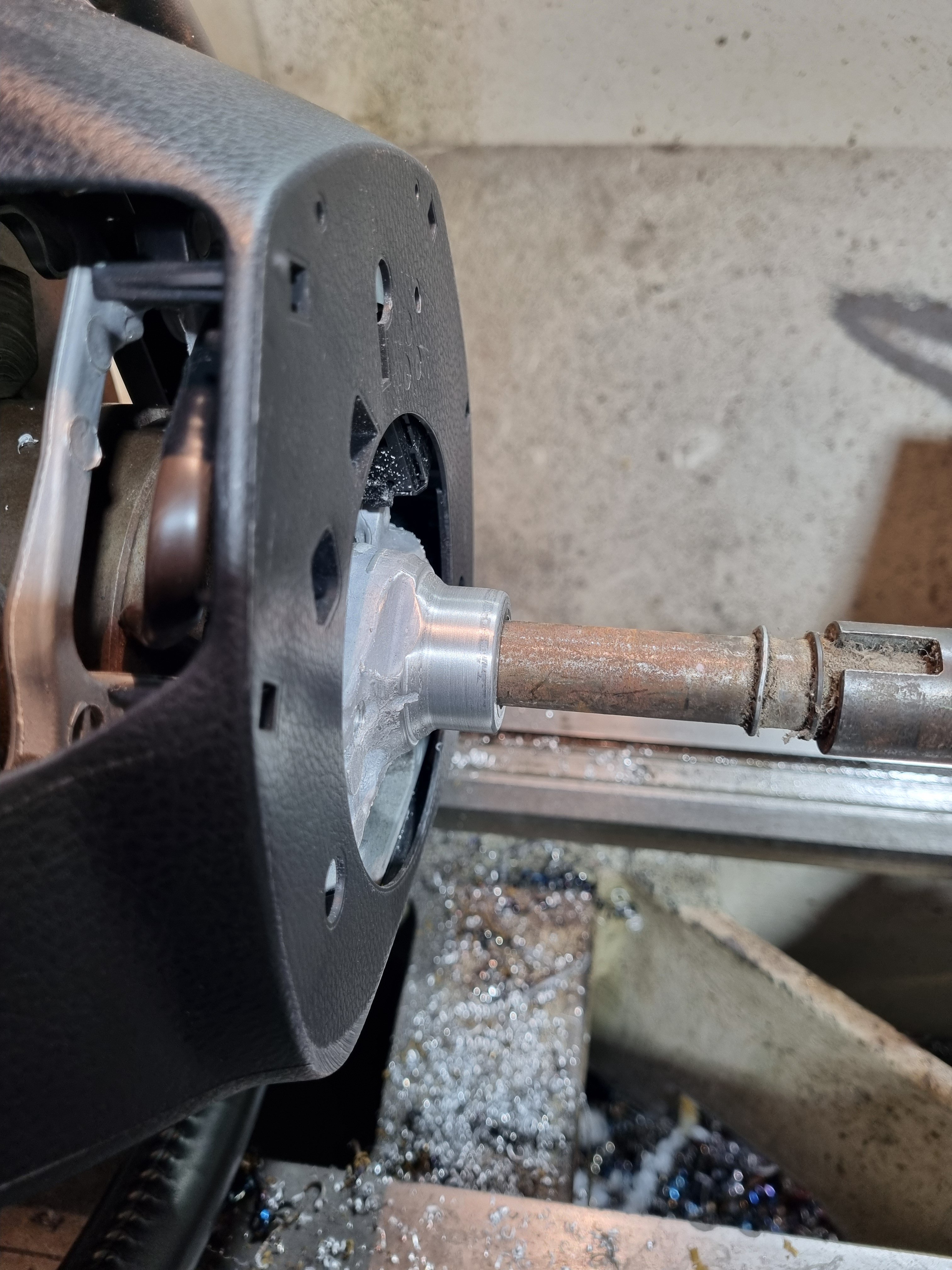
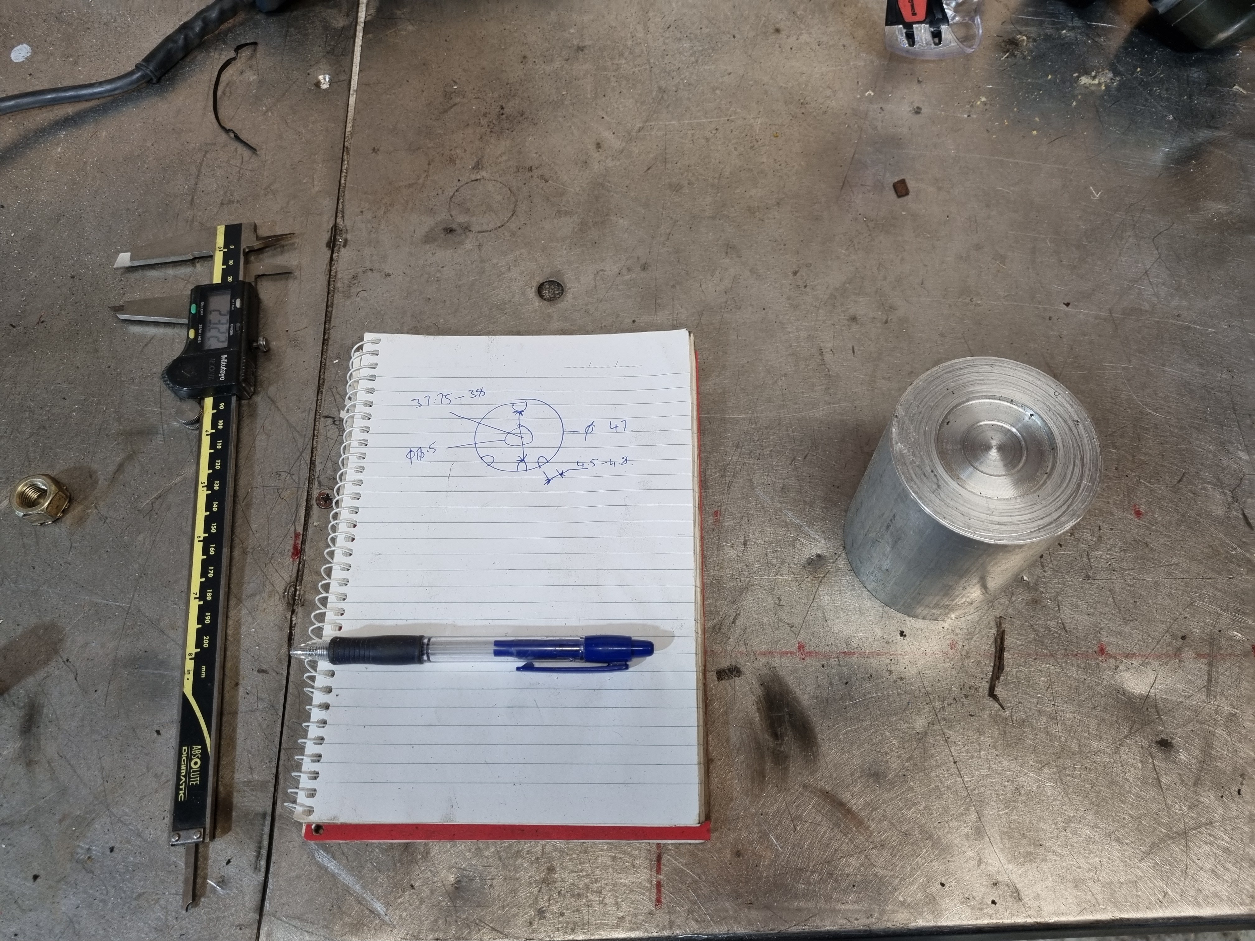
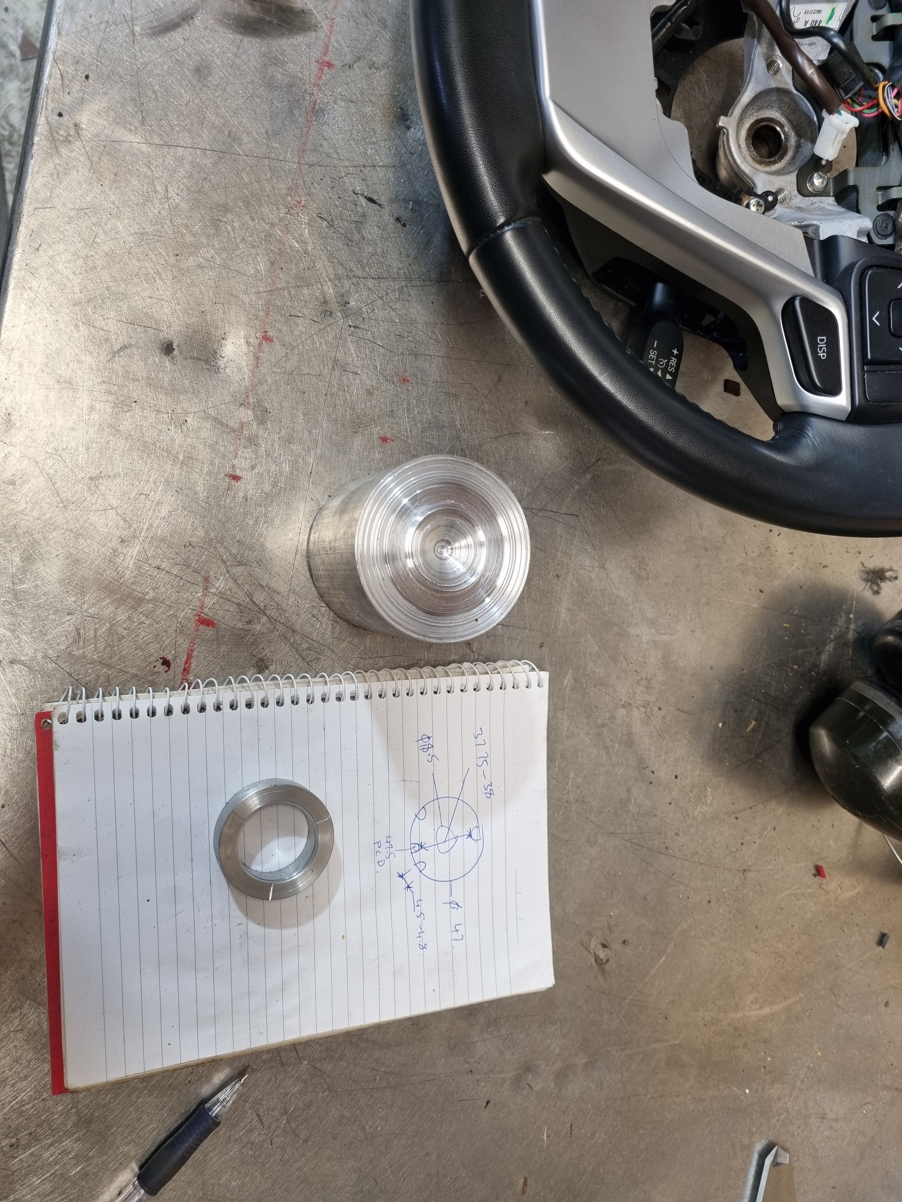
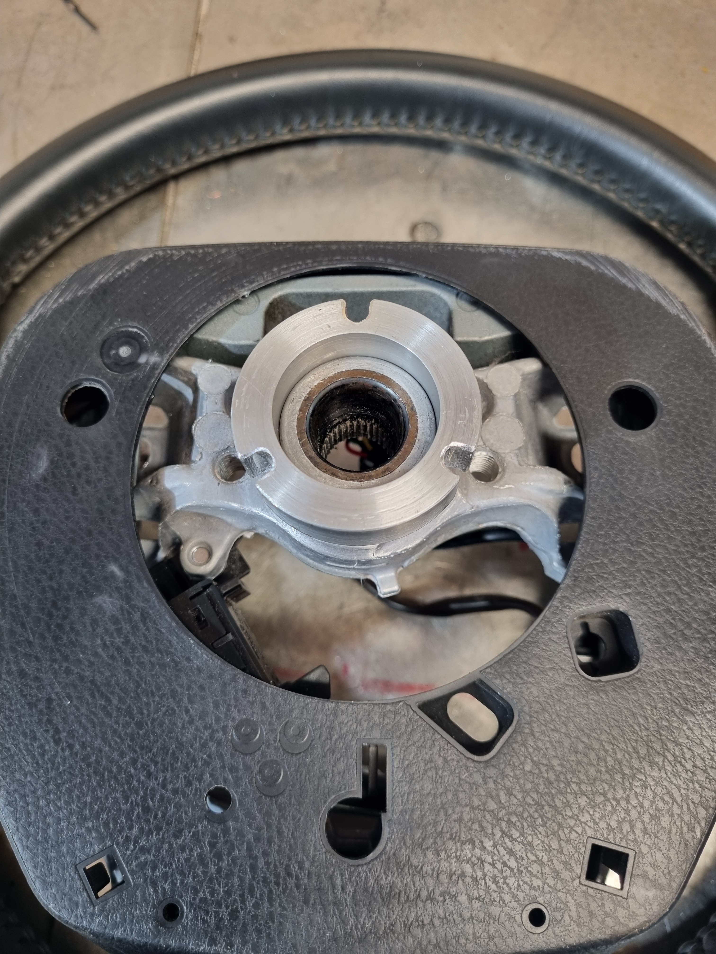
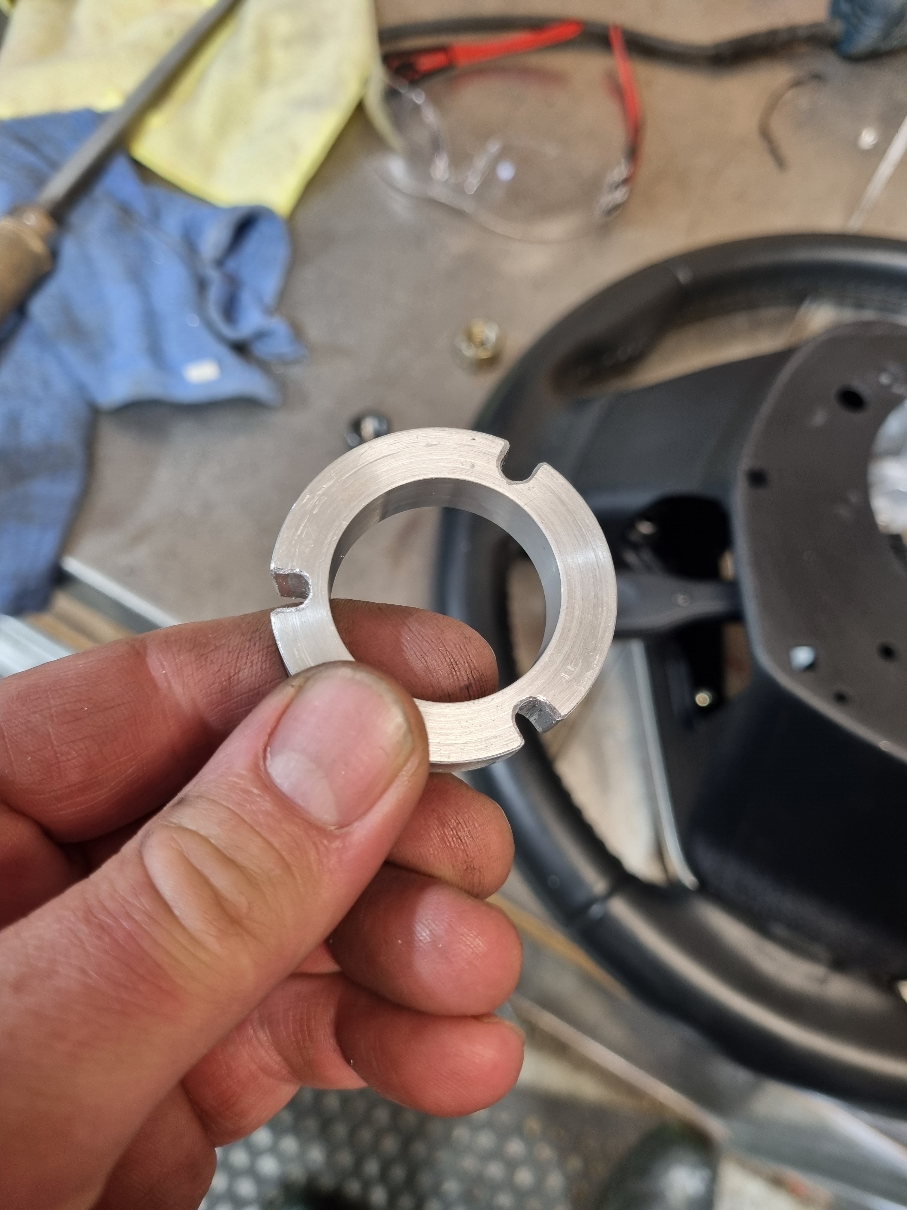
Story time/ going down the rabbit hole. The issue- I never did any homework at all when it came to buying this blaupunkt head unit. If I had of I would have very quickly been made aware of how crap it is. Is unusable as far as changing the volume, shipping tracks or doing anything. Its physically impossible to change the volume accurately, and most of the time is not possible at all. Totally my fault for not checking a single review or anything. So, present day me (well yesterday me actually) was yarning to Nick the sparky about steering wheel controls and clock springs and whatnot and he said "I've got a 2013 Highlander steering wheel, see it that fits" It does. I needed to make a indicator canceling wheel to adapt the new wheel to the hilux. Not super difficult, made a frankinstien rig up to machine a parallel diameter in the back of the wheel. Them made a ring that I will shrink onto the back of the wheel once I confirm its fits the truck. Then the next hurdle will be getting signals through the clock spring. It has 3 spare wires that aren't used so we can use those to send signals to the head unit. But there are probably other clock springs that will fit the truck that have more wires if we need it.
3 points
-
All of which I have on order.3 points
-
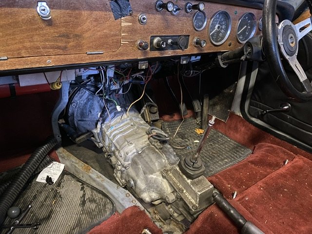
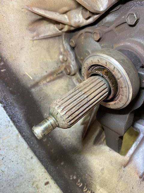
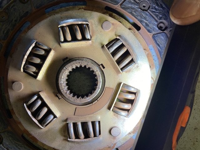
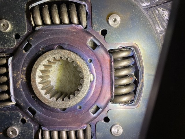
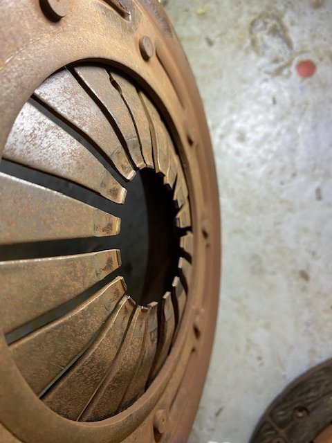
About 20 years ago I got fed up with whining, grinding, leakingTriumph gearboxes and managed to shoehorn a Toyota W58 from a Supra into my Vitesse. I couldn’t get much sense out any of the companies offering conversions (whether in NZ, Oz or US), and anyway I’m cheap, so I made my own. Some detail on that here https://triumphowners.com/to-car/vitesse-mkiii-efi/ (Scroll down to special interest projects). One of the challenges was the clutch. What I ended up with was the original Triumph pressure plate squashing a friction plate listed for a 70s 1.6 Hiace. It was 200mm rather than 215mm and a bit thick, but it worked. Spigot bush was a modified oilite top-hat bush fitted to the flywheel (oe bush is in the crank but Toyota shaft too stumpy to reach). The release mech including bearing and slave cylinder were standard Toyota Supra. After about 10k miles it was becoming obvious that the clutch had problems. Odd noises when taking up and lots of shunt when trickling along in traffic accompanied by clanks and squeaks from the bell housing. Managed about another 5k and pulled it apart. Basically, the sprung centre was disintegrating and the springs utterly crushed. I put this down to the combination of the springs always being too light for the 2L torque and it being a rather crappy QH aftermarket plate. Managed to find a better quality one and slapped it back together. All good for about 10k miles (some of them very hard miles) before the noises started again. Engine was done too so everything came out for a refresh. Once again the sprung centre was collapsing with very crushed springs. This time I splashed out and bought a bespoke 215mm friction plate built for the application from Helix Motorsport. It was expensive - seemed well made. Also used a brand new cover plate, machined the flywheel to take the OE Supra ball-race spigot bearing and spent some time checking concentricity and made some minor changes to doweling. I also did some detailed measuring and determined that a 5/8” M/C should give the correct throw. I had been using 3/4”! Once back together it worked beautifully. Light action, biting point mid-stroke, plenty of bite. No more excessive shunt. Only concern, slight squawk from the bellhousing on initial pedal pressure. Anyhow, got some miles on the new much fiercer engine, mapped it. Went for a hoon around Europe. All good. Except….. after about 5k, the biting point was near the floor. Then on the floor…. Then under the floor. Could find nothing wrong externally, so I cheated and fitted a 0.7” M/C. Problem solved. Slightly heavier pedal but otherwise good. Apart from that squawk. Fast forward a few years and maybe 8k miles and preparing for another European mission, I have my wife drive the car as practice and she struggles because the biting point is once again on the floor. I cheat (again!) a stick a 3/4” M/C. Problem solved. It’s a bit heavy now though. So, in the last 4 to 5 years and 12k miles the biting point has continued to go down. Or rather, it’s been getting wider. That is, you have to crush the carpet to get it to clear, but it doesn’t fully bite up until right near the top, and how much bite comes in at what point in between seems variable. Yesterday I decided it was time to stopping ignoring it (apart from moaning about it) and investigate. Wrestling it out is a bit of a mission. Some of the bellhousing bolts are very inaccessible, it’s probably my fault (consequences of various mods) but the Audi design guys would probably give me 8/10. Two marks deducted for not using Torx/triple hex heads. This bit looks normal-ish. Bit grubby and the plate is very sticky on it ….. and there’s loads of backlash! Spline in my expensive Helix plate is completely borked. This is what it should look like (this is a 200mm Exedy plate) So, that’s part of the problem. The plate hanging on the splines would explain the variability and possibly some of the long travel. Also…. This looks distinctly unpromising. Especially since only about 28k miles in total. That’ll be the squawk then…. Friction surfaces all look fine. Plate is 1/3 worn at most. It’s never slipped. So what’s going on? - Misalignment is a possibility though I’m struggling to see clear signs. - It is possible (probable) that the release bearing profile is wrong. It’s the Toyota one for a 250mm clutch being used with a 215mm cover. The Triumph release bearing doesn’t fit the carrier (2mm smaller ID, very thin wall on the carrier) - It’s possible that the cover assembly is poor quality. Can’t remember where I got it.Its marked QY13039. More QH crap? -That spline though. What has done that? Never seen anything like it. I’ve still got the last plate I used and the spline on that is perfect. Expensive and crap? -Will do some more measuring today to check the release mech geometry but I don’t think it’s the problem. I have new Sachs cover intended for a Saab that usually works very well, but obviously the friction plate and release bearing need more thought.. Thanks for reading. Ideas welcome!
2 points
-
Very jealous, very cool, beautiful stuff.2 points
-
@Raizer machined the cast v-band adaptor housing to fit/work with a v-band flange Sat the turbo in the engine bay now the Ac compressor is sitting there and there is more space than I was expecting, even with the stock manifold in place Plan is to have a coupler from the turbo into the intercooler The intercooler should (will one way or another) fit just in front of the vertical brace for the bonnet support behind the bumper2 points
-
top of the Old Man Range. sent from Airbus A320 Carmichael at Anaheim 1!!! Watch him through the dragons back!!! Look out James Stewart on the Geico Powersports NBC110 makes a move on the inside! He might go for the triple here!! also fuck yeah. get a load of this big ass johnson of a rock Crew at the top of the old man. So much cheese.2 points
-
2 points
-
Bum dyno says the orthia has more midrange and it certainly feels nicer to drive. The Mrs says it feels better too Had a few hours to work on the shuttle today. So younger me did think about removing the loom and put plugs inside so it was easy enough to disconnect. Not the tidiest work but its been functioning for 10 ish years like that so I must have done something right. I'll be redoing it all anyway The car is a mess as its storage/I've just thrown stuff in it Rare NZ new povo spec AC delete vent out The EF sedan evaporator bolted in nicely The low-pressure hard line even bolts up nicely I have two options for the low pressure/suction side, I can cut and attempt to braze the hose (with r134 connector) onto the ef hard line. Or see if I can get the flex line crimped onto the EF line and fit an R134 service port adapter2 points
-
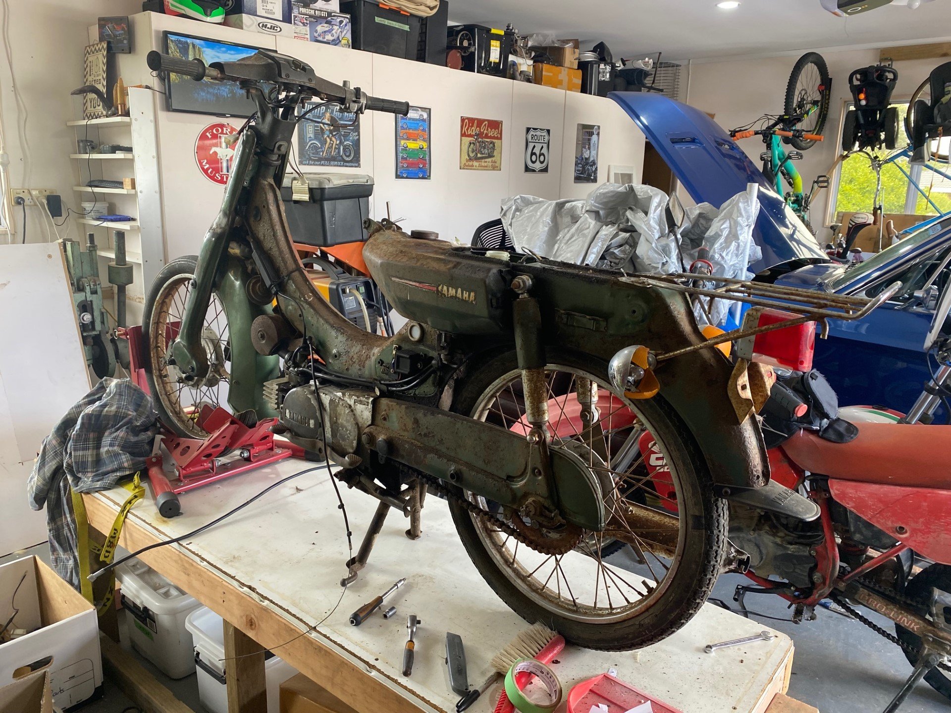
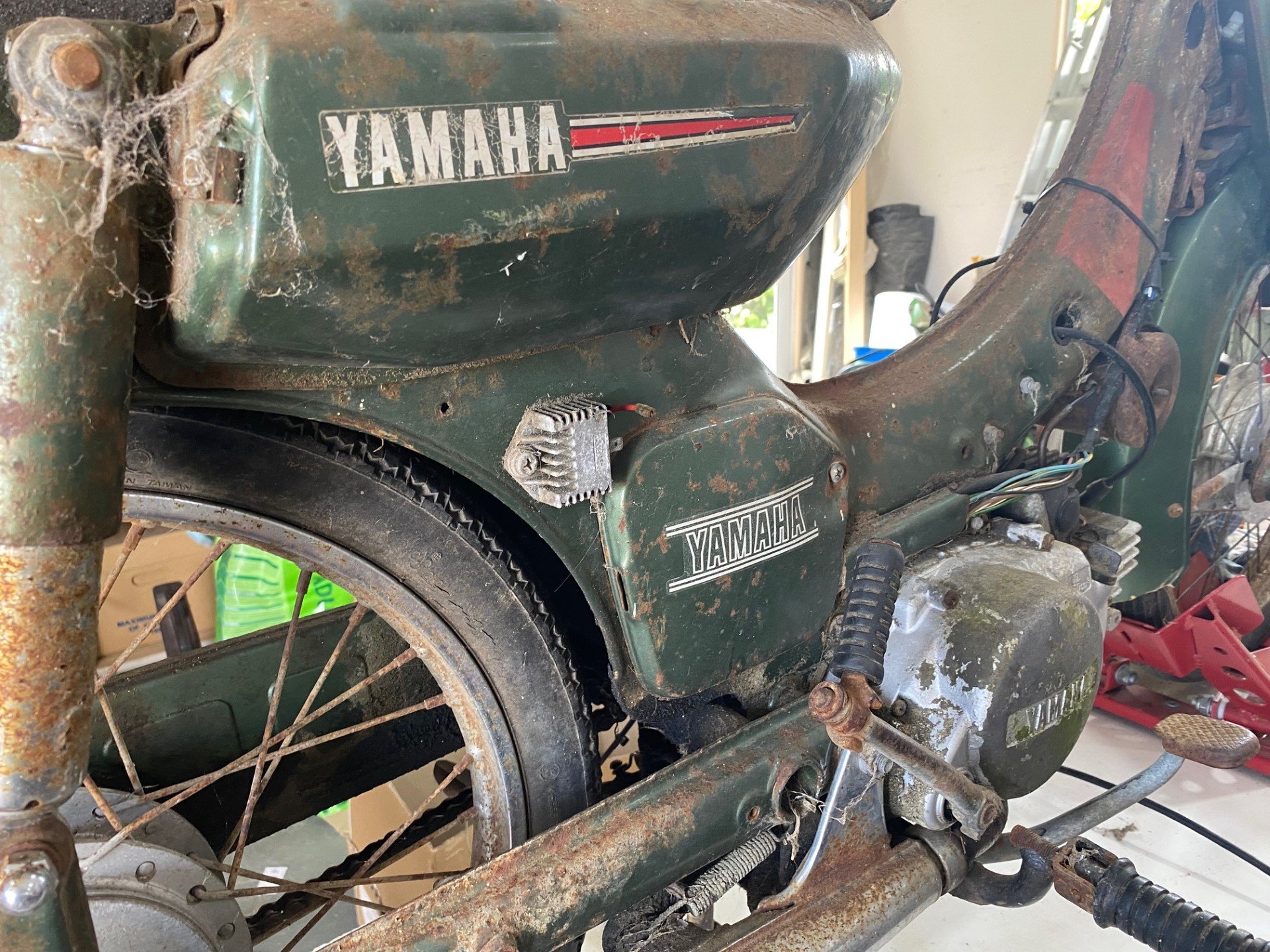
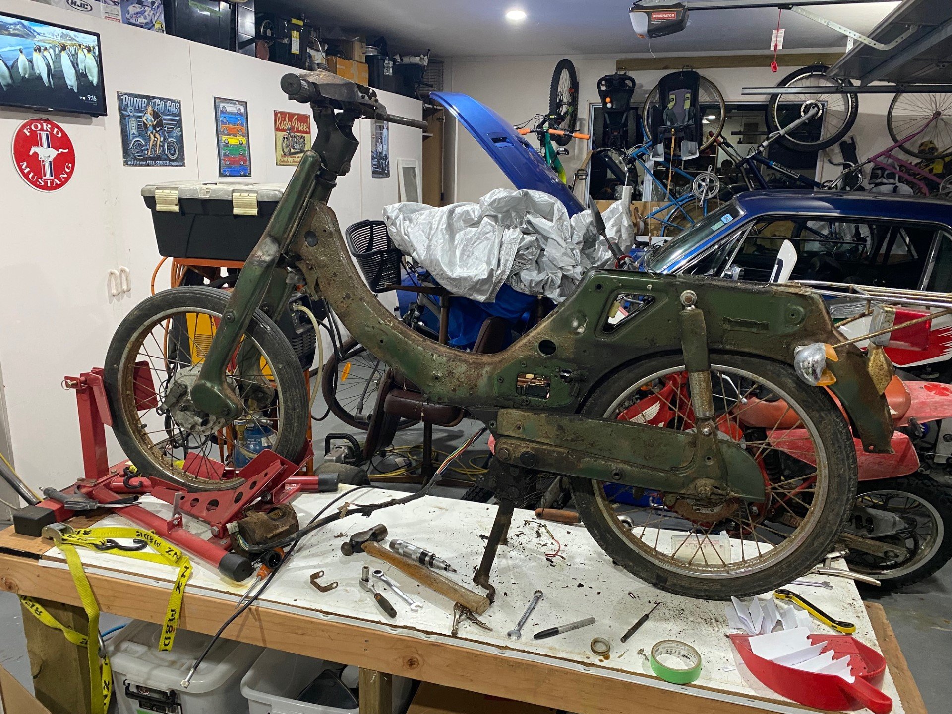
This weekend in pictures: Been stranded at home with the whole family sick, so went to the barn to get something to work on. Unable to decide between finishing my ST90 or starting on the V50, I decided whichever was going to be easier to collect was the weekends project. Its now all stripped down ready to start blast & paint, and I'm about to order the missing bits from Japan. Stoked to finally be working on a Yamaha!
2 points
-
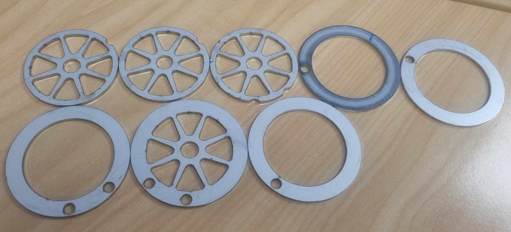
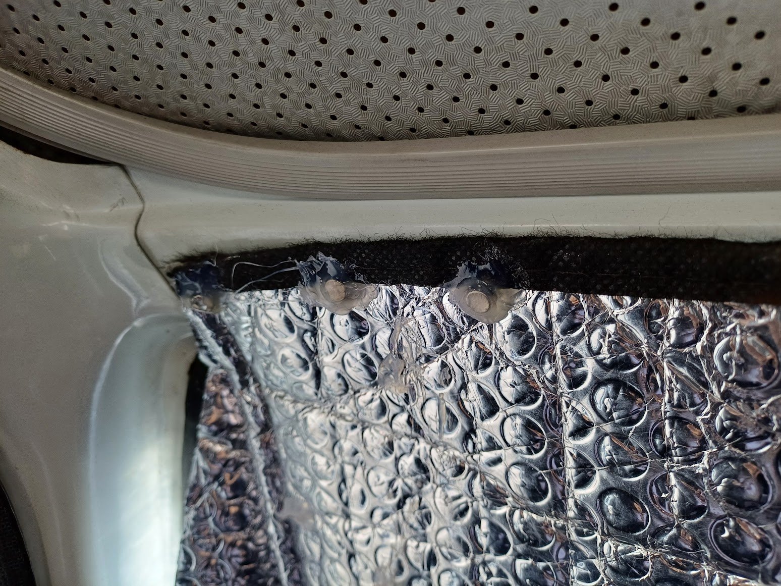
Scrape it all out and run a bead round the join. Smoo it out let it dry and then do a 2nd bead/smoo over the top of that. I used sikaflex 291 because thats what I had lying round and it seems to stick well to the alloy of the bands2 points
-
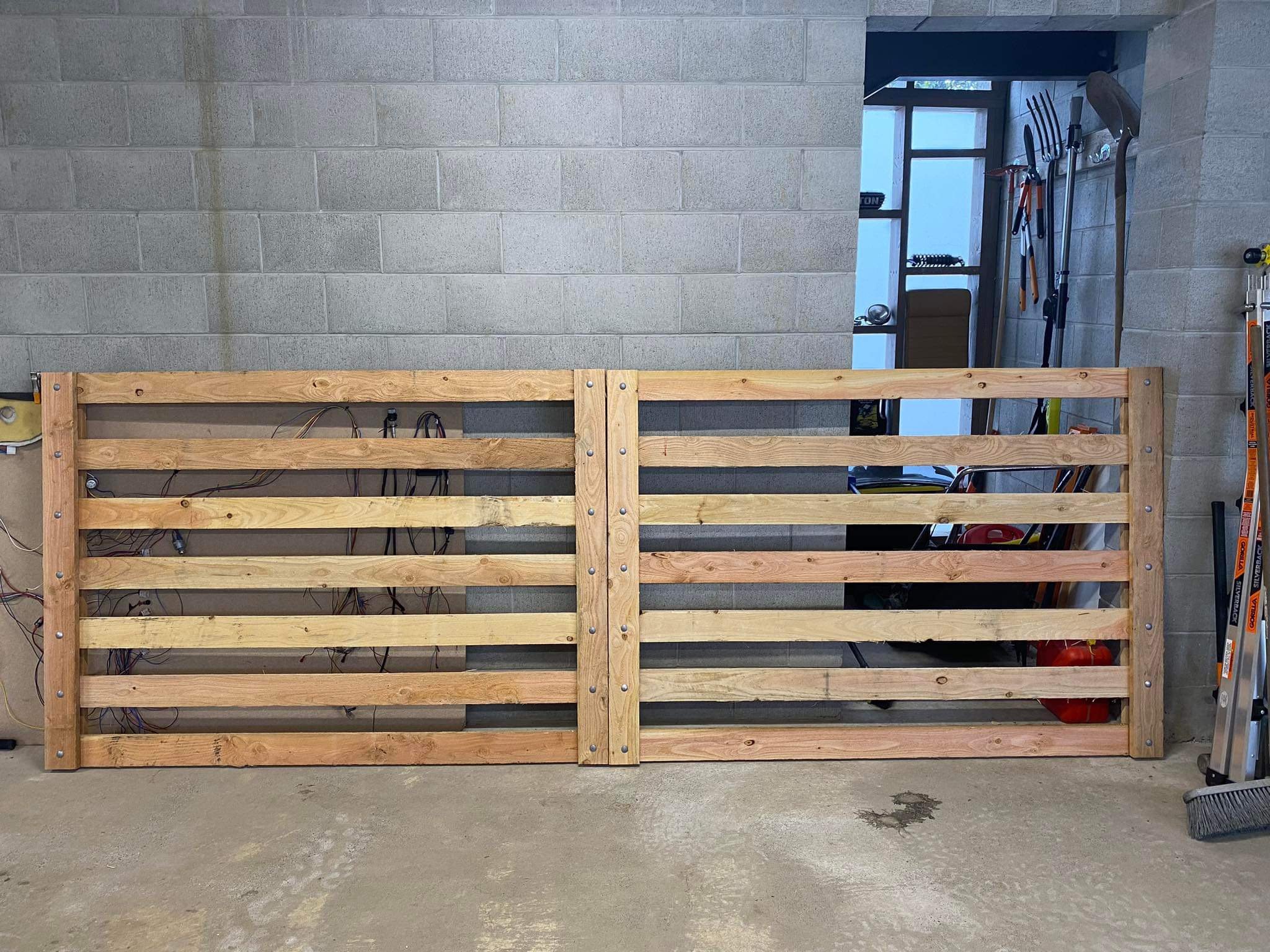
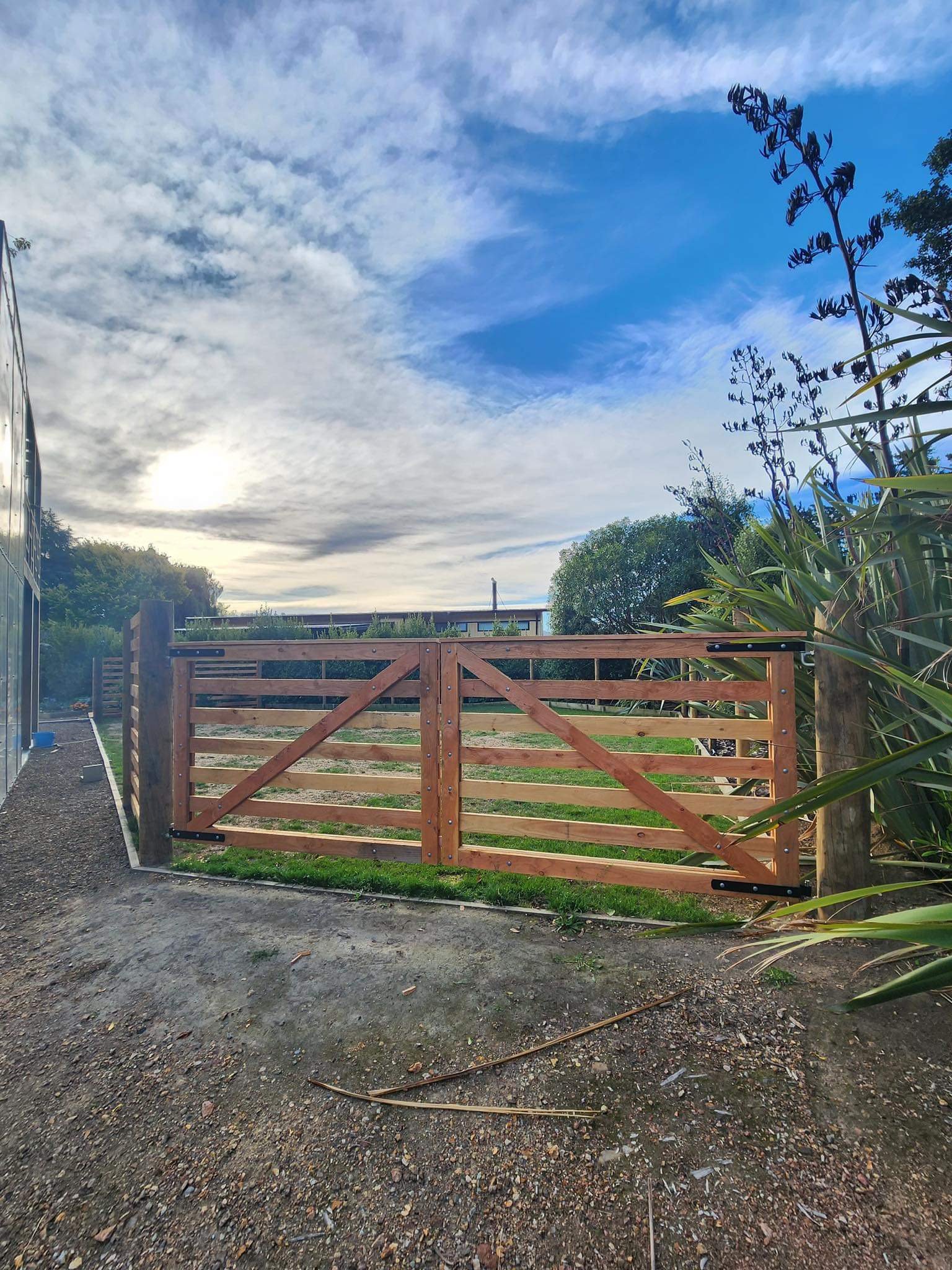
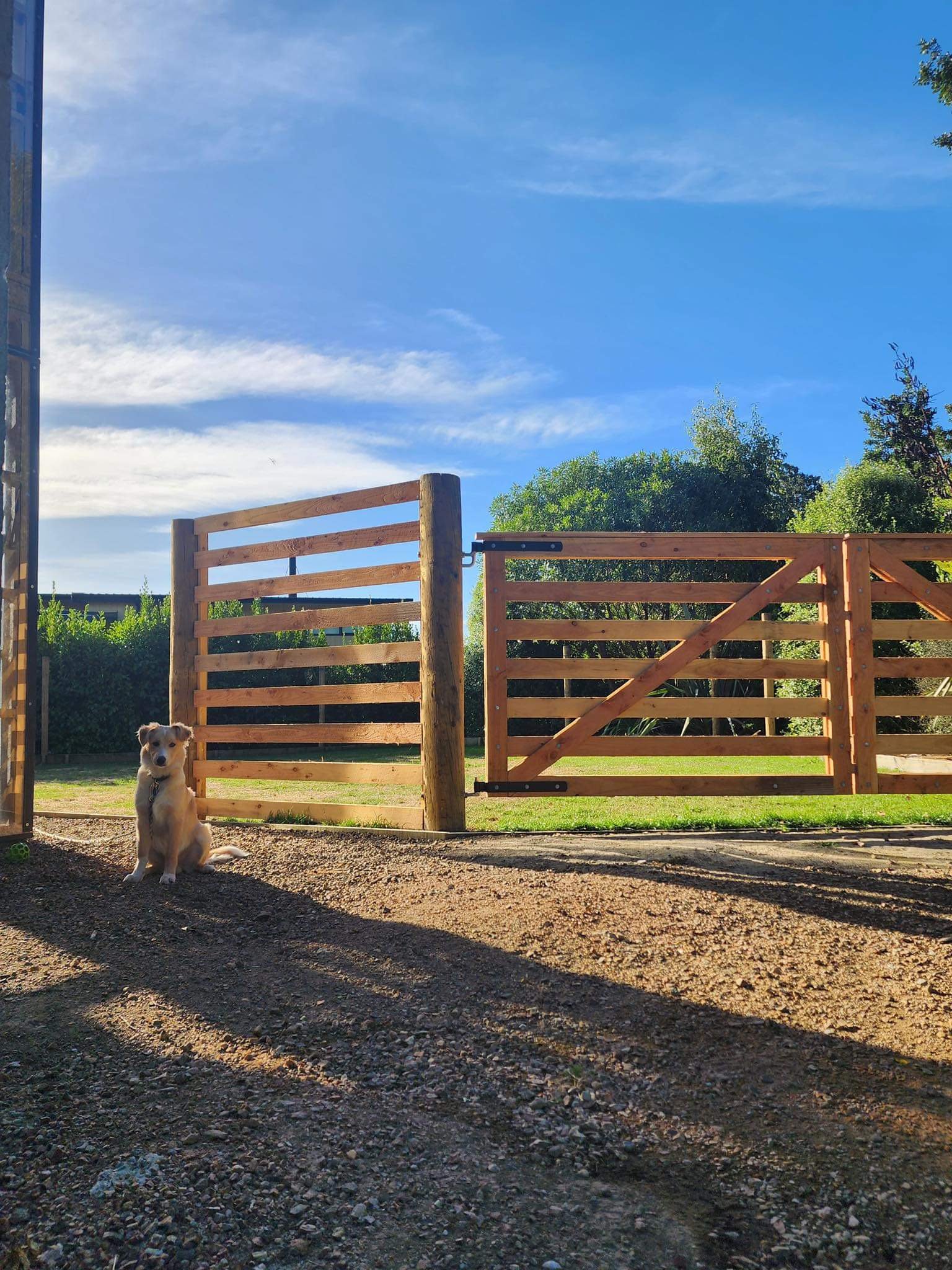
Made some gates so Finn has a nice place to hang out off the lead. Gates are 100x25 Oregon and 200mm round strainers for each gate post buried a meter per side, pretty sturdy: He was keen to show that he could still escape if he wanted to… Alcatraz it is not… yet…
2 points
-
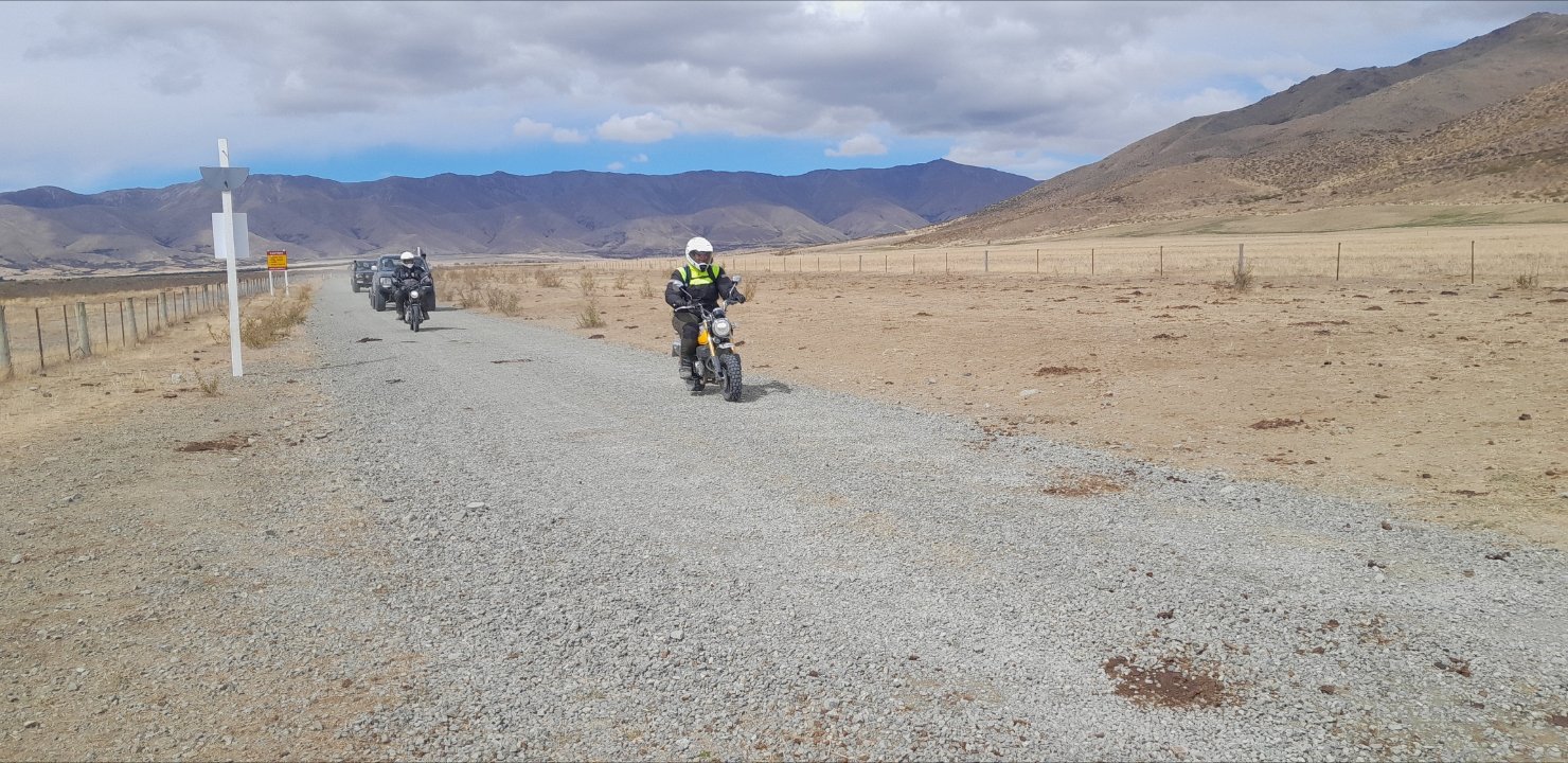
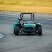
A bit of dust on the camera
2 points
-
2 points
-
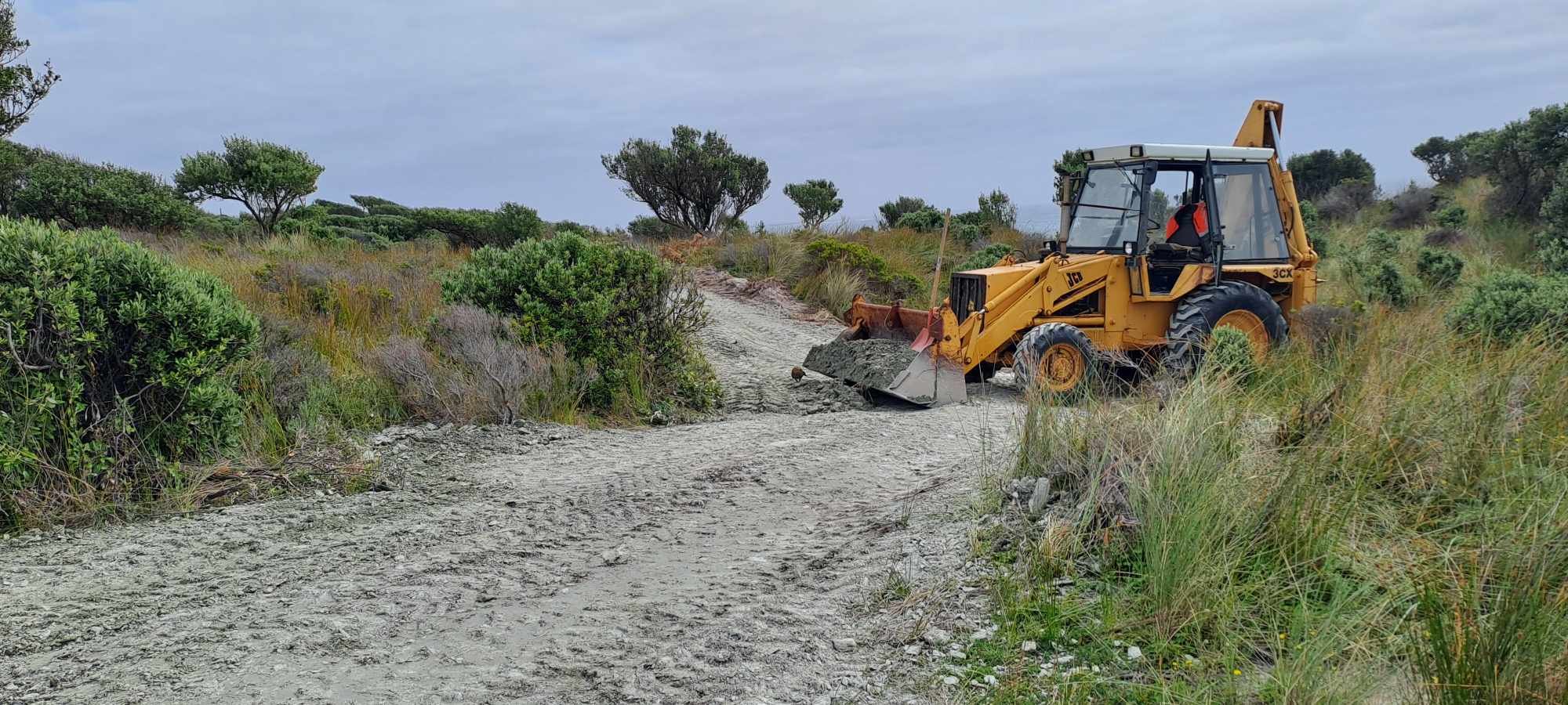
I spent most of the weekend carting schist and extending the driveway. The JCB is finally operational but oh lord it's slow and noisy. Still much better than a spade and a wheelbarrow
2 points
-
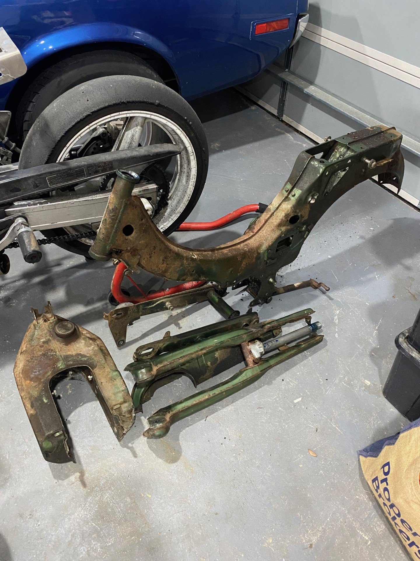
Well its a month later and I am getting back on form, hence this effort today; Plenty of room to finish off the wiring now. There was a minor mishap during engagements, now I need to figure out which Fiat Uno that distributor is off. I'll give the donk a clean up, new oils and filter, new plugs etc. Might drop the sump to see the state of play. For some reason it has way more oil than it actually needs, not sure why.2 points
-
2 points
-
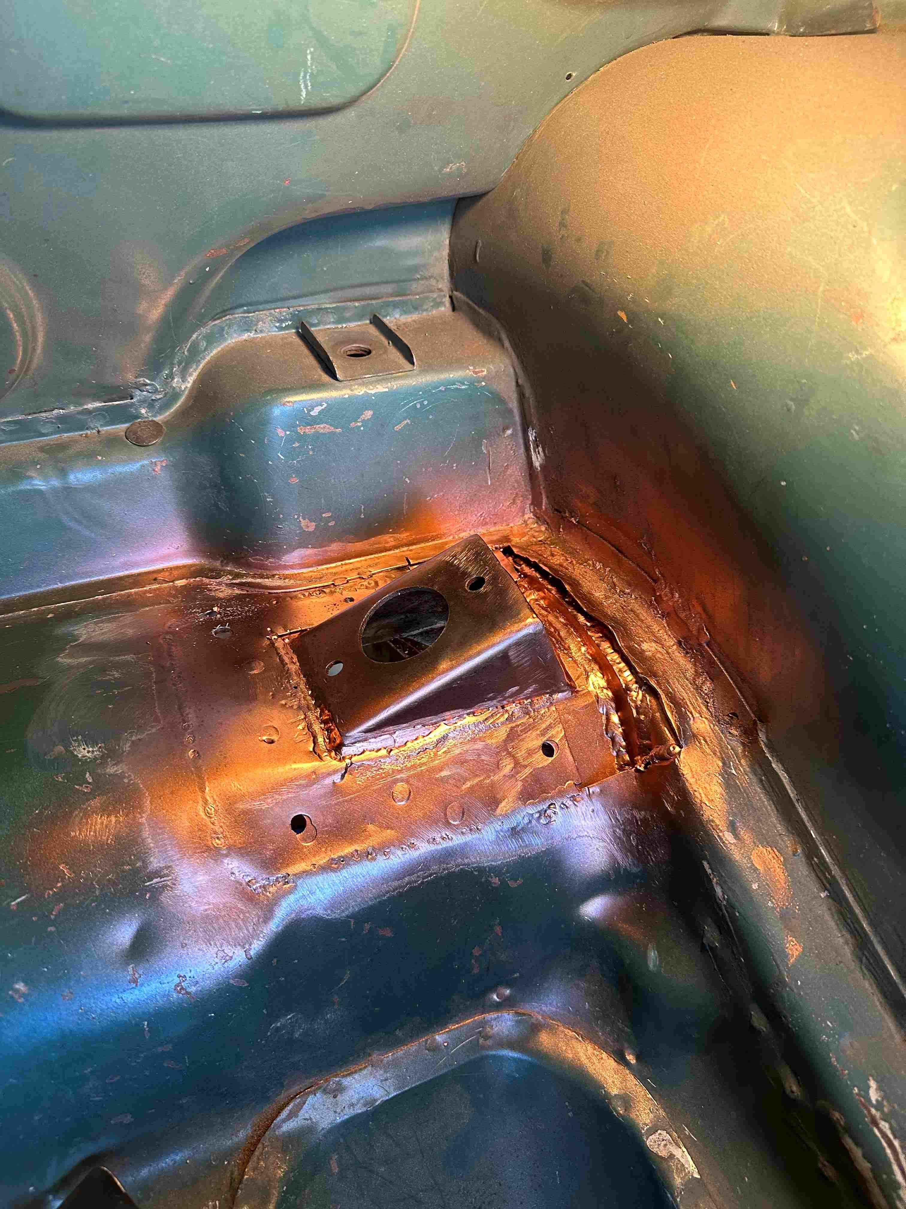
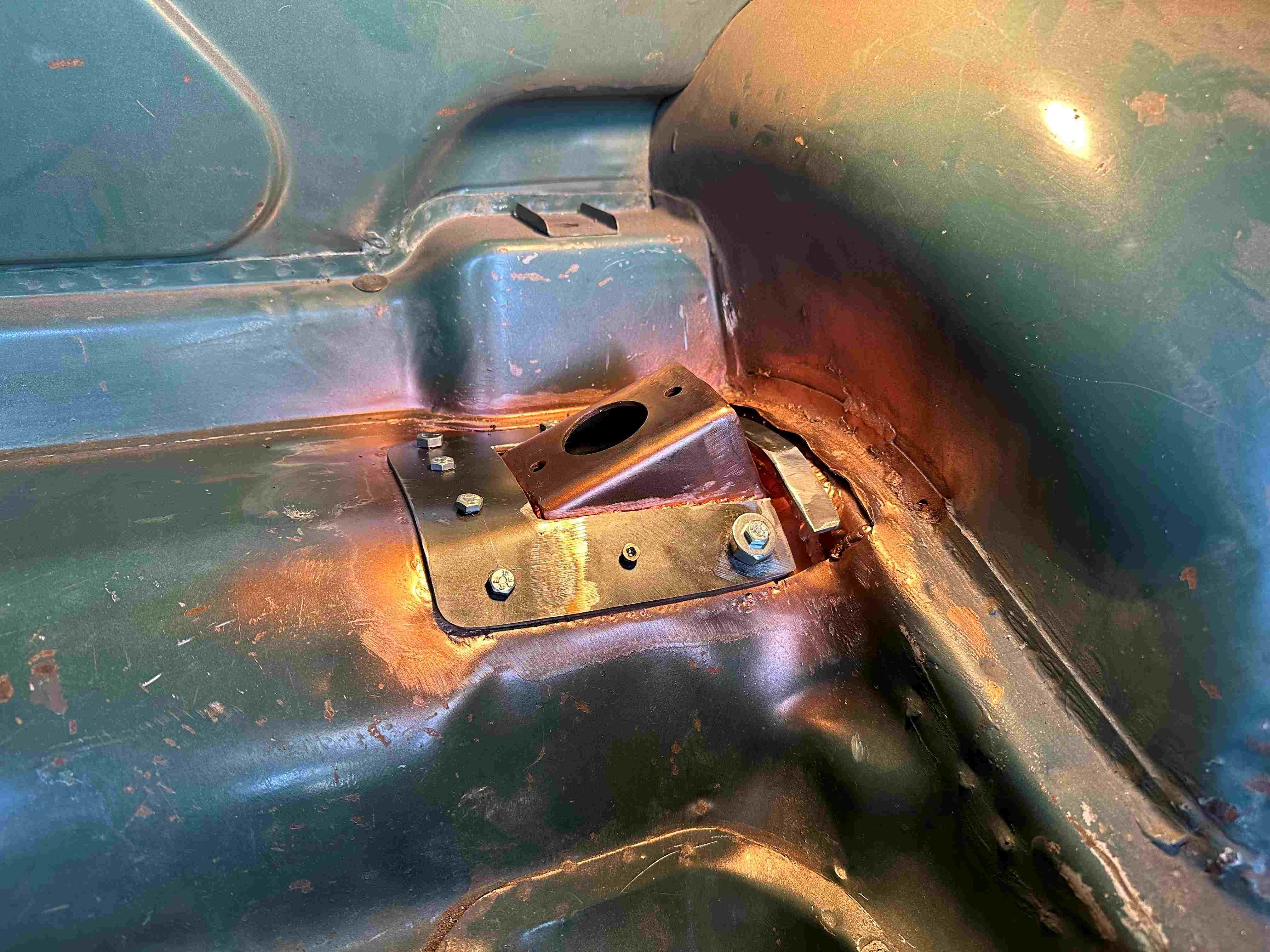
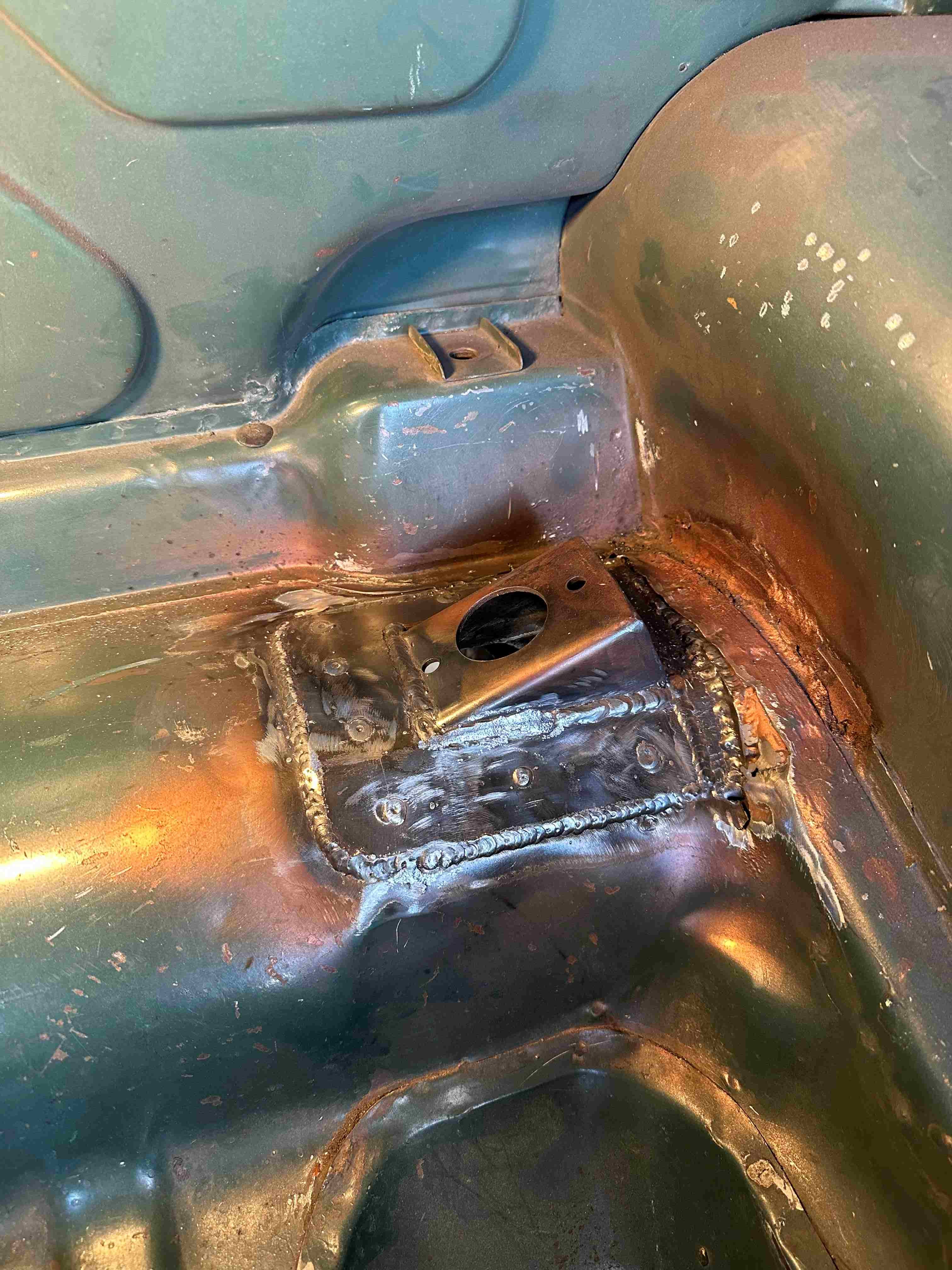
I managed to get the driver side welded in. Man, that took some time. By the time I clamped it in place (the easy bit) then put the 4 bolts in to hold it to the boots sheet metal. Then used some metal screws in between the bolts to hold the sheet metal to the shock mount. Then welded the bracket to the boot floor and the chassis fish plate. Once that was welded in I had to fit and weld the top plate which sandwiches the boot floor between the two. I made the top plate a little smaller in size so when I welded it, I was welding to the weld and bottom plate so I could use a bit more heat. Same procedure with bolts and screws and then welded it in. Welding went well really (well I think), though not that easy being folded in two inside the boot for some of it. Should have taken the pic before I sprayed on the weld through.
2 points
-
2 points
-
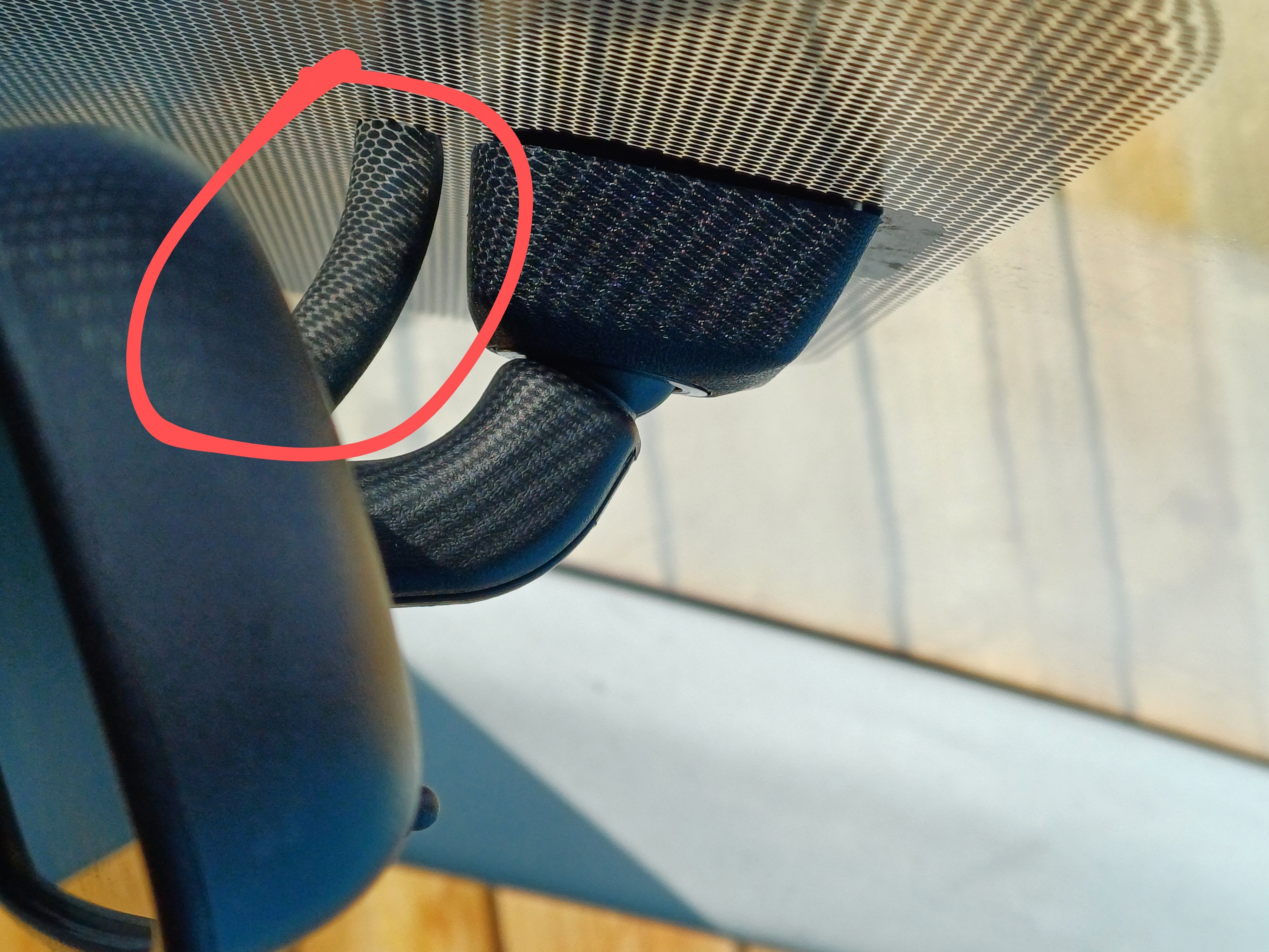
Some small car enhancements, as opposed to some small car enhancements: Prius rear-view was vibrating a little on the trapezoid mount on the windscreen. This is a toyerda. We don't need that crap. we have other crap to enjoy. I got a bit of random skanky hose, put a scallop cut in one end to nudge the mirror stem. Boom. I now have crystal clear view of the cops following me who have zero interest in the Prius I'm driving. I'd cut down an window shade for the Dai, but it's missing a sun visor to hold the passenger side, so I hot-gooed some left-over Neodymium magnets to it. Now I don't have to bother fixing the actual problem:
2 points
-
So up with slightly blurry eyes this morning, after a evening of sometimes literally blowing the cobwebs out. Clean sheet baby! Spent the rest of the day cleaning and polishing. Celebrated with a drive to Bunnings and had a sausage In bread. Couple details to finish up in here, idle is a touch low but starts sweet.
2 points
-
Legit tho what beauty country pretty jelly1 point
-
Thank you for wearing pants whilst taking the pics...1 point
-
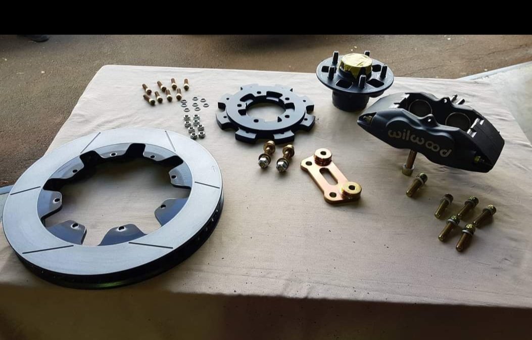
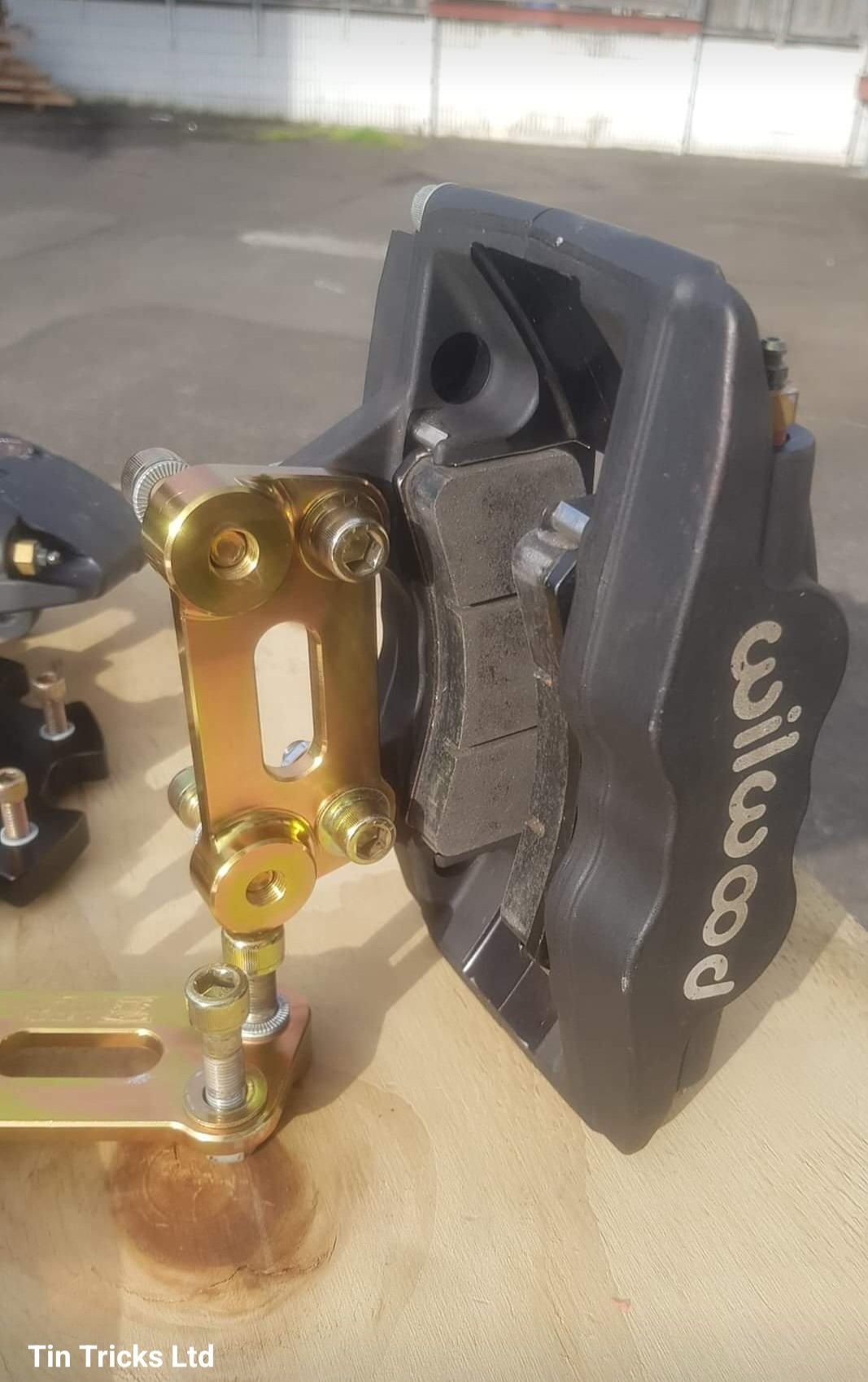
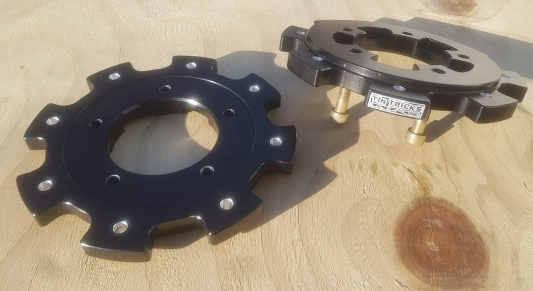
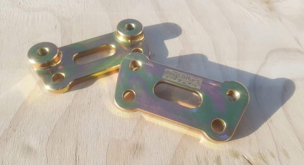
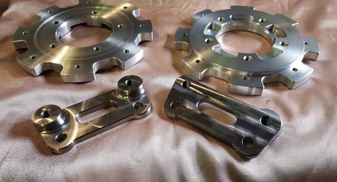
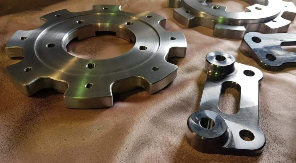
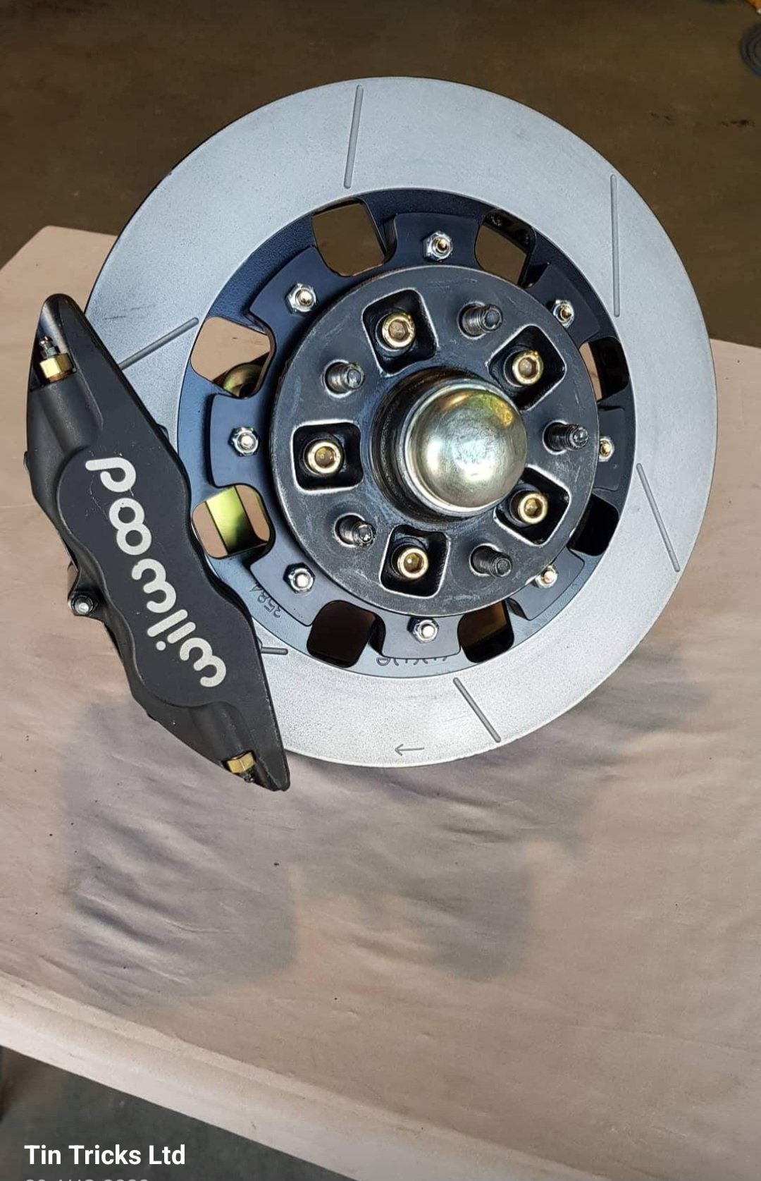
"The front TinTricksMfg bracketry kits for '85-'00 2wd Hilux hubs consist of... ▪︎2x billet 6061-t6 anodized alloy hats ▪︎2x billet p20 zinc plated steel brackets ▪︎complete zinc plated fastener pack to suit -The billet 6061-t6 hats are a hubcentric, bolt on adaptor that mount to the back side of hub the same as the oem rotor would. The rotor is also located centrally to the hat by the lip machined in on back side. 8x 5/16" fasteners attach the rotor to the hat. The hats are anodized for corrosion protection. -The billet p20 steel caliper brackets adapt the aftermarket caliper to the oem spindle caliper mounts. Ease of fitment & fastener/tool access has been kept in mind with bracket design. The brackets are zinc plated for corrosion protection. -Fasteners used are suited to a high-heat environment. Grade 12.9 cap screws zinc plated and post heat-treated. Hardened flat washers with Nordlock & Schnorr locking washers plus zinc plated cone-lock nuts. These kits are built to comply with New Zealands LVV Braking & Attachment Systems Certification standards and discussions with our local certifier were had throughout the design process. They are 100% bolt on with the oem hubs, and are made to work with oem or drop-spindles. (Minor variations may apply between spindles/castings) >>Note: kits suit 17" wheels upwards. I will confirm caliper clearance via private message. ALL PRICING IS IN NEW ZEALAND DOLLARS AND INCLUDES GST. OPTION 1 >>Hat, Bracket & fastener kit only (both sides) $1300.00 with natural/clear anodized hats $1335.00 with black/colour anodized hats (Minimum run of 10 hats needed for bulk anodizing prices otherwise a one-off charge applies) OPTION 2: >>Complete kit with Rotors, Calipers, Brackets & fasteners. (excludes brake pads)(both sides) $3085.00 with natural/clear anodized hats $3120.00 with black/colour anodized hats (Minimum run of 10 hats needed for bulk anodizing prices otherwise a one-off charge applies) -Rotors are Wilwood 13.06"x1.374" (331x34mm) Gt48 curved vane slotted & vented. P/n: 160-3584c (Right) & 160-3585c (Left) -Calipers are Wilwood 4-piston Superlite forged type. 1.75"x1.10". P/n: 120-11135 (Note: extras you will need to buy are brake pads with a compound to suit your requirement, plus brake hoses/fittings.) * Copied over from Matt's business page1 point
-
Bench testing continued. The sump was now holding oil. Phew. I fitted the old smiths mechanical oil pressure gauge that was originally fitted in the imp race car. I mounted the gauge to the temporary coil stand. With the engine cranking over it was seeing about 20 psi. The oil level would drop in the sight glass and after a minute or two it would be back to the old level. I was happy with this. Next on the list was to check the idle control valve was working. Its a 2 wire Bosch style pwm type unit. Very common, simple, reliable and hence used often in megasquirt installs. Its basically a rotary valve that is opened against spring pressure by a solenoid windings when current passes through them. The ecu earths its ground wire in a series of pulses, the quicker the pulses the more it stays 'open'. Simple as I thought.. but.. this is where I discovered that I had bought one of the units that is actually 'closed' at about 30% duty cycle. A failsafe on cars that use these for closed loop idle control (aircon/powersteering/epic sound systems etc etc) If the valve fails then spring pressure actually takes it to a slightly open state so the car cant stall. But I'm only using the valve for open loop at start up. So when its closed I want it to be closed. Luckily I was able to pick out/burn/pick out/burn/pick out the tough as epoxy that was holding the valve stop adjustment screw in place. I wound the screw in until the valve was closed with no power. It still passes a tiny amount of air but its much better. I'll manually adjust the idle bleed screw on the throttle body to get the fully warmed up idle where I want it when that time comes. Which was going to be soon I thought! Next thing to check was that the crank angle trigger wheel VR sensor and the camshaft half moon hall sensor were both putting out satisfactory signals. Opened up the composite logger on tunerstudio expecting to see nice clean signals. But there was nothing. My heart sank. Oh here we go.. I took off the cover on the main board plug and checked the connections there. I then popped the volt meter, set at AC volts, onto pin 1 and 24, wound the engine over and got about 2.0 volts. I don't have an osillioscope and only have an old megastim 2.2 testing unit which won't create the required rpm signals I needed for testing. I wasn't quite sure what to check next so I started a thread on the megasquirt forum. Got some bits of advice but in the end I rang a mate in Richmond who has a lot more knowledge with megasquirts and has helped me out in the past. Organised to go see him the foloowing day. In the meantime I checked the hall sensor. I had never been able to find confirmative details on the polarity of the hall sensor even though it was a really commonly used unit among many a citreon/fiat/renault etc. I finally found a factory service manual online for Fiat ducatos which had a pin out of the sensor. Turns out I'd got my polarity wrong and after swapping the wires around at the hall sensor plug I now had a strong clean cam signal. I also made a mandrel to hold the old honda 12-1 trigger wheel in the lathe. Then I made two jigs. One for the spare goldwing VR sensor, like the one I'd fitted to the engine. The other jig was to hold a Mazda V6 VR crank sensor of which I had a few kicking about and had used them with no issues on the Viva. I spun the trigger wheel up in the lathe at various speeds and took voltage readings of both sensors. The readings were very similar but I still couldn't tell what the actual signals are like. The next morning I drove out to mates place and he set to work on my ECU. He compared the board to his spare Ms3x. looking for any differences. Remember I had bought this ECU secondhand from someone on trademe and was told it was working. I had swap some of the circuitry jumper wires to suit my application. Once he was happy there was nothing major missing on my board he got another spare ecu he had and ran up my sensors in his test bed to confirm they were putting out a good signal. Then we (well - mainly him, I just stood about and learned) systematically went through the VR circuit looking at the signals on his osiloscope. Discovered that transistor U7 was faulty so he kindly swapped out the known good item from his MS1 which I'll find a replacement for him. After that he found a loose, terribly soldered resistor in the circuit- when it was wiggled the signal would appear.... re-soldered that and hey presto - clean signal. Lots of other pins got re-soldered too. The Goldwing pulse generator/VR sensor puts out a much weaker signal that the Mazda crank vr sensor. we double checked them against each other and the Goldwing item struggles at slow speeds (cranking type speeds) so I'll swap over to the Mazda item. When I got home I quickly tried the repaired ecu out and now there's a good rpm signal but it drops out of sync but I took a log anyway. Then started making a new bracket to suit the Mazda sensor. New vr sensor in place and wired up. I then had to remove one cambelt, which is so easy to do on these engines, remove the trigger wheel, file off the old key and weld a new one in place to suit the mazda vr sensor position which was now bolted in the other set of holes Honda used for the original 'pulse generators' as they call them. New trigger wheel key peg.. Finishing that lot got me to this point when trying it out that evening... The red spikes indicate an out of sync situation and no rpm reading but at least the log was clean, consistant and rythmic. Something wrong in the settings, not interference. I tried changing various trigger settings but no luck I was tired so off to bed. Following morning I discovered that when I was changing the trigger settings I didn't spot the prompts to power cycle the engine because I was still on the diagnostics page. So none of those changes took place until the very end when I had actually set it back to the typical default settings. This time a power cycle after changing the capture to falling edge and I got this lovely log... Yay!!! Now I was ready to check the ignition coils and then the base timing. What else could possibly go wrong? Coils all tested fine and the sparks were nice and clean looking. I then marked the timing mark on my custom crank pulley and tested the base timing. I was out by 4 degrees. Pretty happy that I had got my trigger wheel so close. Simply changing the trigger wheel offset value in the settings by 4 degrees had the timing marks line up bang on. Engine start up time was here! I went to bed happy, excited and somewhat nervous about what could happen, or not... So this morning it was time to roll the engine out on the table to the front of the workshop, throw some fuel into the mix and see what happens. I set up the garden hose just in case, taped my phone to a light stand, started recording, tentatively went for a start and this is what happened... Wow!!! Faaaaaaaaaaaarking awesome! What an occasion. What a milestone. Such relief and much giggling with joy. I couldn't believe it. First start on my own custom built engine and it sounds bloody amazing! That was starting on a basic universal base map loaded onto the ecu so I was really expecting a lot more mucking about with the starting settings to get a clean start. I was stoked! I tweaked the cranking settings slightly and now it would start on the button after a few cycles... I can only run it for a few seconds as there is not a drop of coolant in the engine. So my next job is to set up a makeshift coolant circuit using a spare Nissan micra radiator and setup the Davies Craig electric water pump. I can test for leaks and then I can really have a good crack at setting up a nice clean starting and idling tune. I'm so happy! Alex.1 point
-
She goes 100mph just sitting there. Pretty stoked. I picked the engine up a few days ago, the guys at Kennally Cams did a brilliant job. I've just been putting the shiny parts on. The bellhousing and clutch kit arrived from Dellow Conversions. On the whole I'm happy with it. The bellhousing is perfect, but I'm a bit worried about the clutch assembly they supplied and would appreciate any input. They supplied a kit to mate the engine to a w57. Pressure plate, clutch, slave cylinder, bellhousing etc. They modified the pressure plate that they supplied. The original ford pressure plate has 6 bolt holes plus 3 holes for dowels that are on the fly wheel. The one they supplied has 6 holes total. 3 line up with bolt holes and the other 3 have been drilled out by them where the dowels go.. But over sized so the dowels no longer locate the pressure plate. That is one of the holes they drilled out. This is it sitting on the fly wheel. I have just had the engine balanced. My concern is that without the locating dowels (they are useless as the holes are now too big) the 3 bolts alone won't locate the pressure plate exactly in the center necessarily. They guys that built the engine don't think it's a good idea to run as is. What are your guys thoughts? I queried Dellow, and they said yeah, nah, it's sweet. Also, the front cut for the radiator suport panels seems to have fallen through. I think the dude literally died. No answer to calls, txt or email. And the shop (kiwi auto) is chained closed. Cheers for any input! John.1 point
-
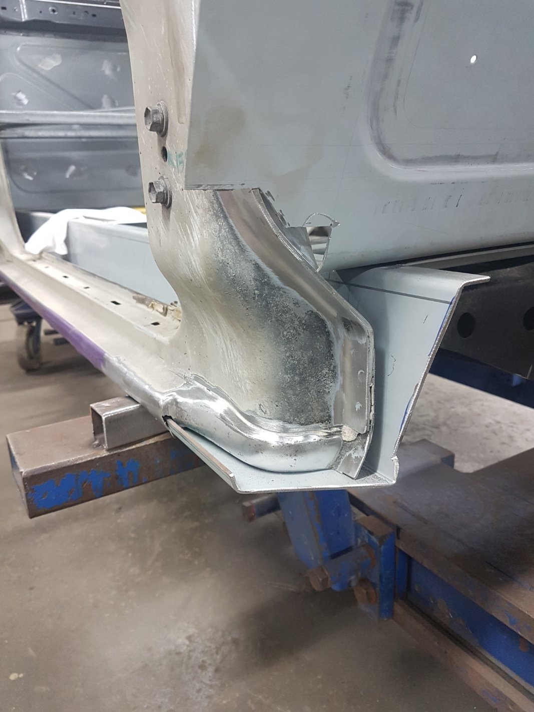
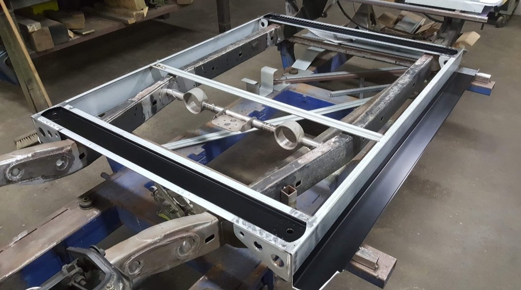
The body drop equates to a 3-1/8" (80mm) drop. Relatively pretty big on a Toyota and cut into the rocker panel Here's the sill panel folded up and construction of the floor structure
1 point
-
Hello ThePog I believe I have come into ownership of your old x1/9. I'm sorry to say it has come to me in rough shape. However I thought I would get in touch to see if you would be interested in it again?1 point
-
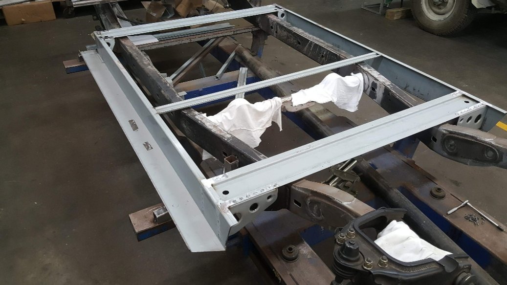
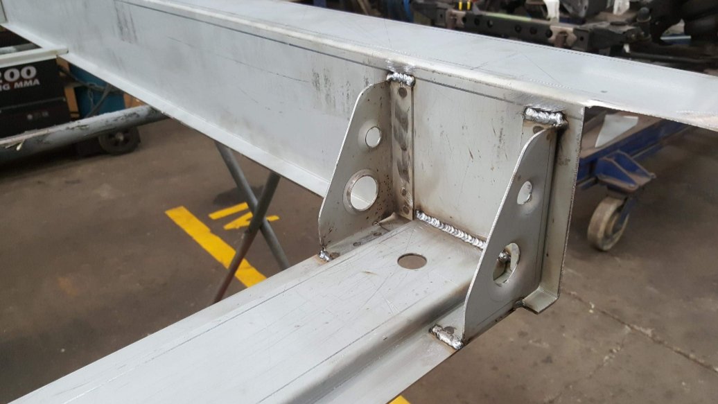
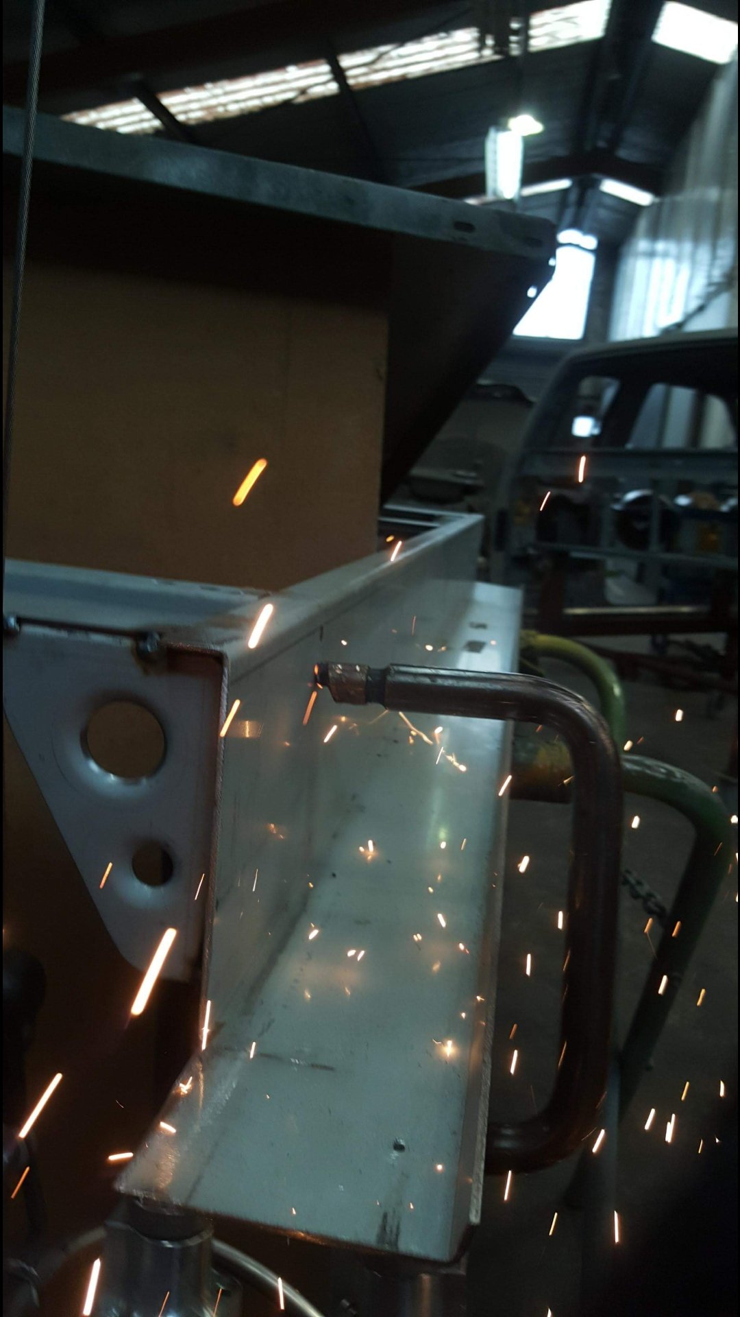
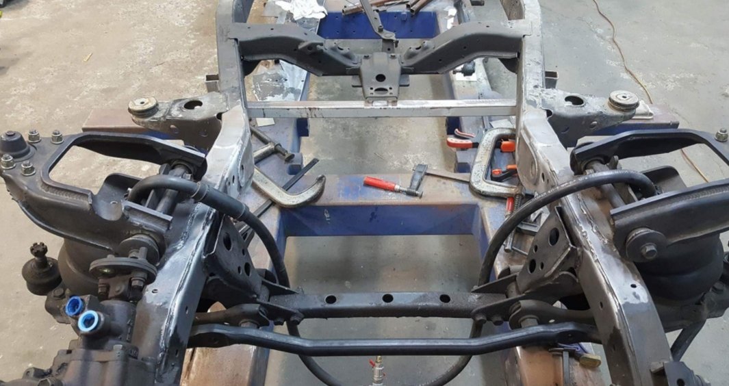
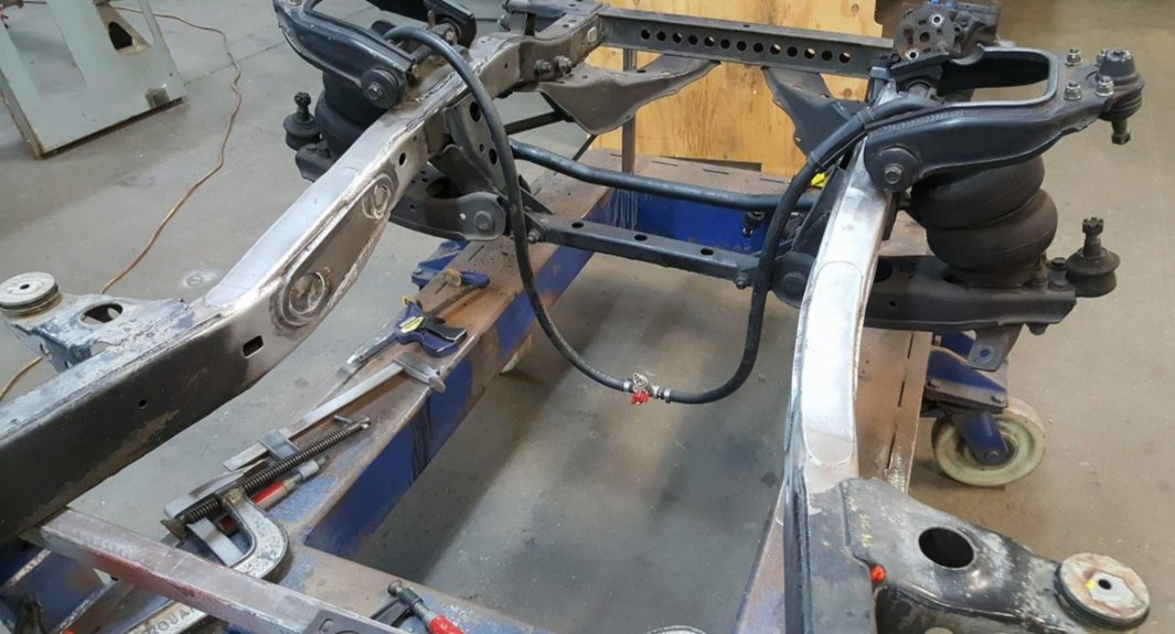
Z'd front clip update, On a Hilux, unlike a Mazda b series when they are laid out they dont lay a full chassis rail, the back half does and then they sit on the engine cross member. So to get around this the front section of the rails are lifted, and the frame horns on the front are lowered to accommodate. Im not sure how much of a raise Matt went with on my chassis, but here you can see what's involved with the process, and then final fish plates welded in too. Also I actually had some frame damage that was pulled, either from a previous collision while it was on the chassis table.
1 point
.jpeg.3d2734e1be46c4b230b2cafddc6c95e6.jpeg)


.thumb.jpeg.e0a4bff61111e0c8c7396950fcc94da1.jpeg)


.thumb.jpg.570970b401ac8d26ce9af7c1bf2bd8cd.jpg)


This leaderboard is set to Auckland/GMT+12:00