
Leaderboard


Popular Content
Showing content with the highest reputation on 03/03/24 in all areas
-
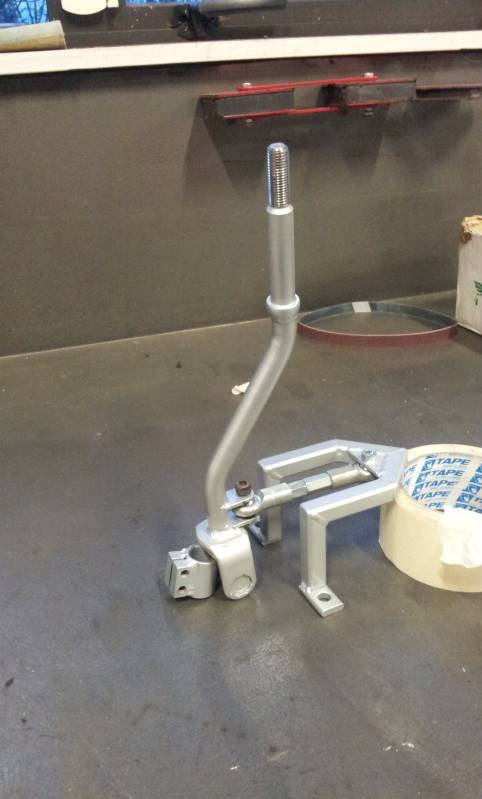
I glooped the two halves together, bolted them up, bolted the tailhousing on and let it set. Following morning it was bolted onto the engine, unsurprisingly a bit heftier with all the gubbins placed back within the box. Its about 9kg heavier than the standard imp box. I then started to fit the first part of the gearshift linkage. The first of those snazzy universal joints, handily available in a diameter to suit the shifter shaft on the Subaru box. I just needed to add a small locating hole for the grub screw... Universal in place.. Engine and box were then bolted back into the car. This bit is so quick and easy when using the 'engine stand 2000'. It takes about 10 mins and I'm getting quicker. It'll be slower when there's shift linkage to undo and driveshafts to slip out of the way. But at least the main heavy awkward part is actually easy. That lot in place I took some pics. Its neat to be able to look out from the one of the lounge room windows down onto the workshop floor and see this... With that lot in place I was able to suss out the angles I could get away with, as shallow as possible and allowing for the handbrake mechanism. I had this old imp gearstick assembly that @dmulally kindly posted over to me. Some previous owner of the car he got it from liked painting things. Everything. Multiple times... I scraped all the layers off, took it apart and cleaned off the dirty old grease. Discovered it had been cobbled together from two old shifter bases. It was originally a very early Imp unit when the very first cars had an automatic choke, which often proved problematic. Hillman then changed the cars over to a manual choke with a nifty little lever in front of the shifter. This mount had been added to the early base. Which means they must have chopped up a later baseplate to get the choke mount. Why they didn't just fit the entire newer base plate I don't know. But what I had in front of me was a frankenstein of base plates with barry spec welding and fixes, but also including a not too badly made bronze bush on the lever where there is normally a (wornout) plastic bush. I had a couple of shift rods to choose from. I chose the least worn. Moving back to the gearbox end I machined up some shaft ends from stainless bar to suit the universal joints. I had some stainless tube and welded the ends in place on the first shaft that runs from the gearbox universal down to the tunnel. Now I needed a sturdy, slippery support to mount in place of the second universal joint. This will not only take back and forth movement on the shaft but also a bit of thrust loading created by the angle on the connecting shaft. I had already bought a lump of slippery hard engineering plastic with this application in mind when I had ordered the plastic for the flywheel thrust bearing a while back. It was bright yellow. Luckily not seen under the car as it would clash with the blue paint. I put a hole in it and machined the outside down. Which also created a pile of pretty swarf.. Then reamed it out to 1" Still a bit tight so out with the adjustable reamers.. until it was just right... Then made a stainless cradle .. The cradle got some wings welded in place and I dug the rivnut tool out.. Mount now bolted in place in the tunnel I had to chop the last tube to the right length, weld on the end and bolt the universal in place.. The front end below the shifter was was standard imp stuff and this is where problems popped up to throw a medium sized spanner in my workings. The side to side gearstick movement across the gate was minimal. Ridiculously so. Like about 1". Or 25mm in new money. Yet the fore and aft movement was about right. But quite stiff. I was contemplating why this was so and what I could do to remedy this when I also noted that 1st gear was where 3rd was and 3rd was where 1st was. Poos. Four years ago when I had compared the Subaru gearshift pattern at the box to the imp unit I thought they were exactly the same. But I had not accounted for the reverse rotation taking place under the imp gearstick. Also I never really thought much about how little of rotation the Subaru box needed on its shifter shaft to shift the internal selector across the 3 rods. Its a tiny amount, like 3 degrees say. Whereas the Imp box has a shorter internal selector and requires more rotation at the shaft. Hence the Imps gearstick knob only moves a teeny bit when coupled to the Subaru box. But the Subaru box has a standard/similar amount of rod movement within (ie 1-2 and 3-4th) which was going to make things trickier to fix. Simple linkage/leverage multiplications that is easier to see than explain. Sorry if your brain hurts. I had to hurt my brain a little bit to suss out a solution but there was only a little bit of smoke. The reason the scooby box is different becomes obvious when you see the scooby shifter setup. Which luckily I can show you because last week thanks to @Leone I was put onto a local fella to me who happens to have many old Leones and Brats kicking about his property and he had a spare leone front wheel drive box that I wanted (always handy just in case...) His property is amazing!!! Long 4wd only driveway up to a ridgetop house with stunning views out over Tasman Bay. Old leones just kicking about... Luckily we have our trusty old 4wd Hiace and that became the days gearbox transporter... Box on bench. Look at that shifter mechanism... The shifter rod attached to the gearstick only rotates a tiny amount when the stick is moved sideways across the gate. But the rod moves 10mm in each direction when shifting for and aft. Simple. Robust. Very Subaru. I can't copy it though because I have turned my box 180 degrees. No matter where I put my pivot point (below or above) I'll have one of the planes working backwards. So I decided to build a new shifter base setup. The most important thing was to reverse the rotation so the gearstick pattern is correct. The imp pivot point needed raising to allow the offset shaft end to be rotated to above rather than below the centre line, so reversing the across gate movement. I would add the ability to adjust both rotation and lineal movement. Started with a new pivot cup because I was not happy with the worn and Barried pressed steel item.. I dug out a large lump of steel bar... Chopped out a square and cleaned it up in the mill.. Big drill = big hole.. Rough machined out a cup shape. Cut a form in cardboard to suit the brass ball and used a die grinder bit to finish the shape... Grinding paste time... Slots for pivot pin.. Lightened the lump down.. Built the shaft up with weld and machined it down so I could add a lower pivot point. Milled some steel like so.. Welded a boss on.. New socket for shift lever ball end... Cut out Barrys previous workmanship... Machined up some spacers and a base plate.. Welded up a little tower (my stainless and steel tig welding is definitely improving, helped muchly by realising that not being able to see what I'm doing does not help much and finally admitting to my age and buying some reading glasses....) Welded tower to base.. Now all together please... Bolted together. You can spot the adjustable rotation, which the spacers allow for, along with adjustable pivot point. In place... Yay- it works! The shift pattern is correct and the action is much smoother. The spring loaded indents on the internal gearbox shift rods are quite stiff, which I noted was the same on the other box with its stock shifter. Its a bit baulky to push past the synchro baulk rings into gear but I think will feel better when the gears are actually rotating. There's certainly no slop in the system and it feels very mechanical - not rubbery. I now note how much flex there is around the shifter base in the imps tunnel (granted a very rusty shell..) Its something I might just try to stiffen up on my blue Imp when fitting this lot in. Phew. That was a little mini engineering mission I was not expecting but that's this project in general35 points
-
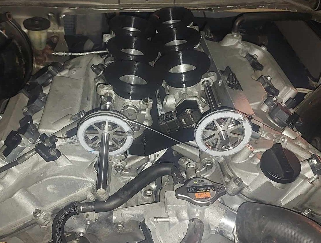
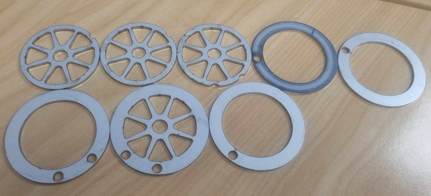
Alright so as of yesterday I'm finally out of mortgage prison! I finished moving house with heaps of time to spare, I definitely wasnt biffing trailer loads of stuff onto the lawn the night before settlement. I got some throttle pulleys cut from stainless. I'll put a radius on the inside of the pulley edges and deburr a few spots, but on the whole they came out really nicely. Quite heavy though, probably could have made some parts thinner. (Everything 2mm stainless) It's looking like it'll be fiddlier than expected to balance the cable length and pulley positions to get the banks even. One thing that I didnt take into account is that there is no tolerance for having a cable that is "overlength" as you physically cant slide the protruding end of the cable into the pulley. However I could probably chop out the relevant section of the pulley to allow this without any issues, as these are still significantly beefier than they need to be. I need to make some end stops of some sort to stop the throttle rails moving forward or backwards so everything stays aligned correctly. You may notice that in this photo I've got the linking cable on the wrong way up. It looks dumb having these on the front of the motor, but down the back is getting very crowded and I've got ants in my pants to get this damn thing fired up. I got the throttle rails drilled, took about 3 hours to drill 6 holes! We had to grind flats onto the rod to get through the hardening. Otherwise carbide bits didnt even make a dent. Next jobs are to print a final iteration of the manifold from Nylon, get fuel lines connected up, and keep working on the exhaust. Then I'm preeeeety close to firing it up!
 18 points
 -
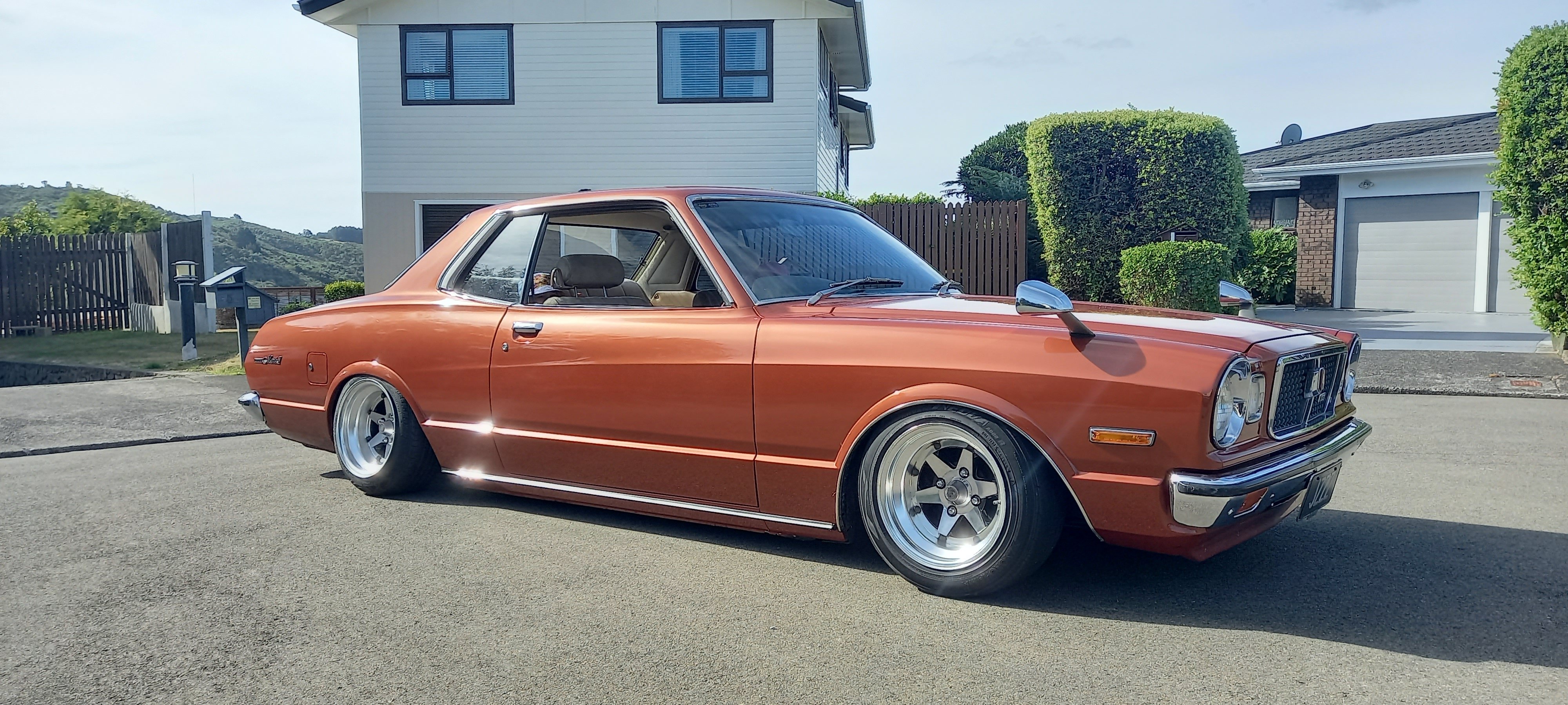
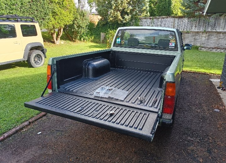
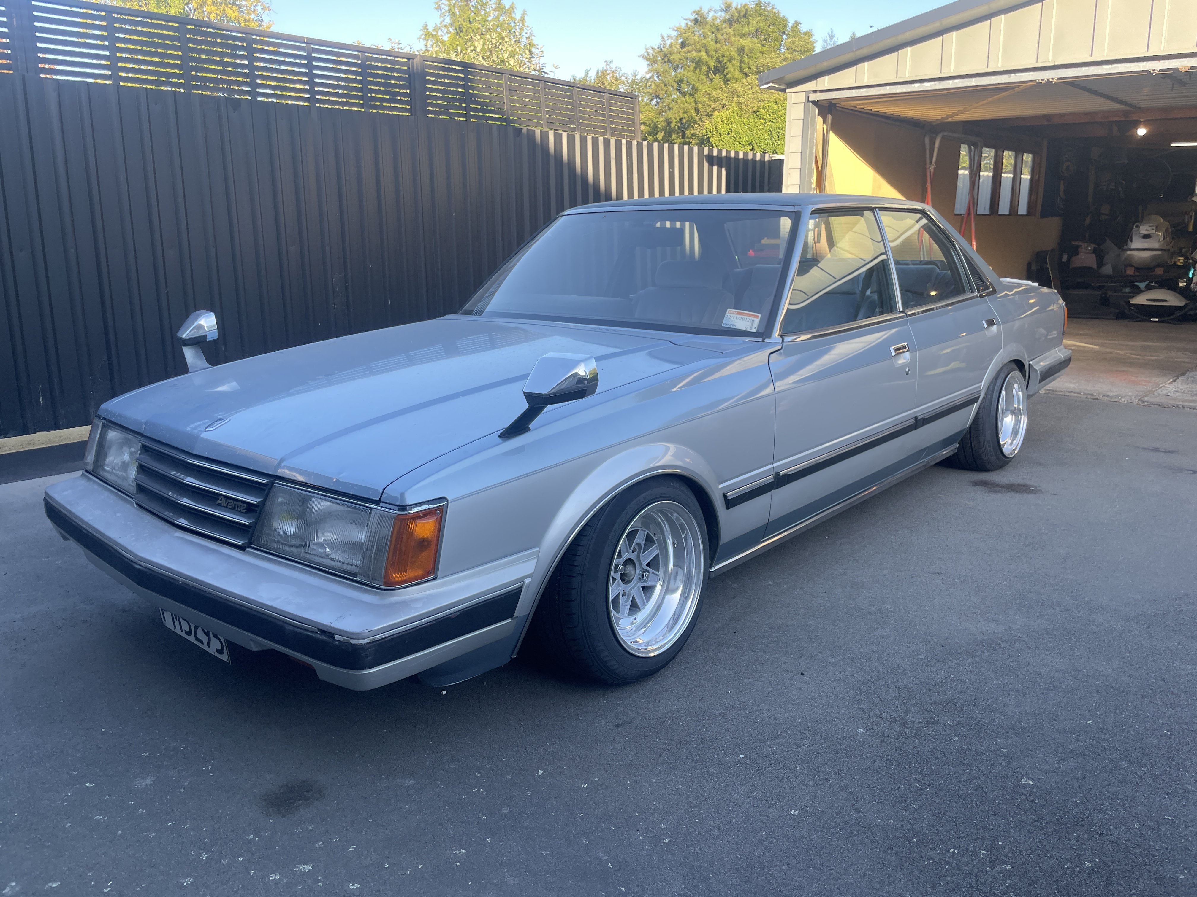
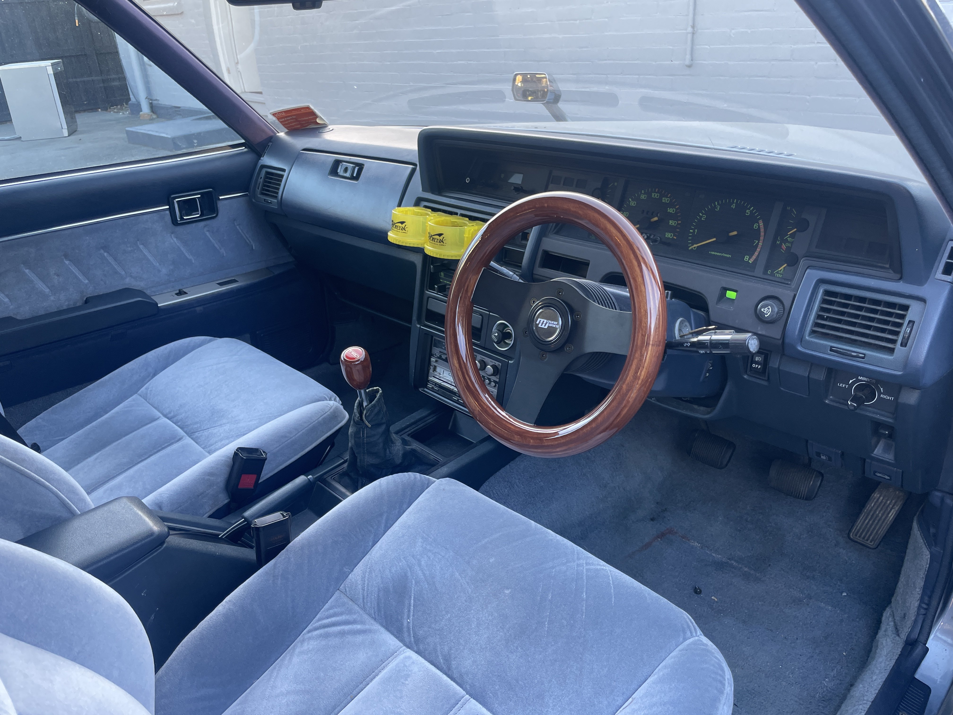
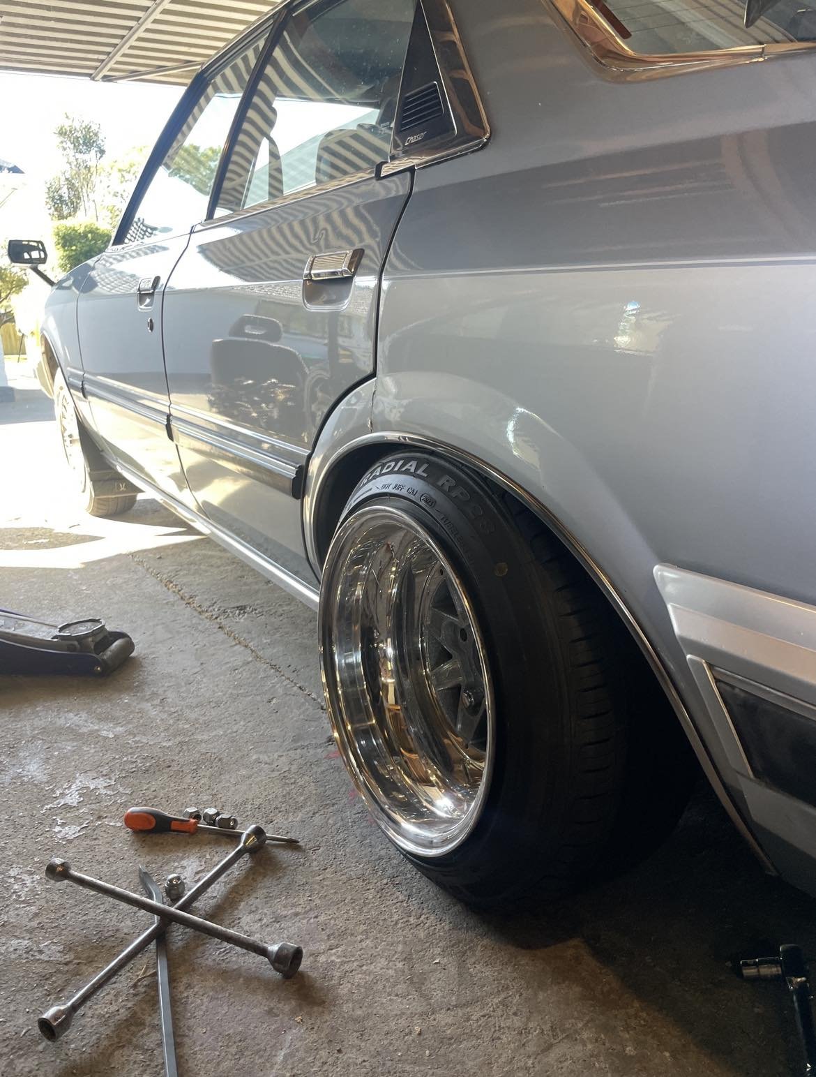
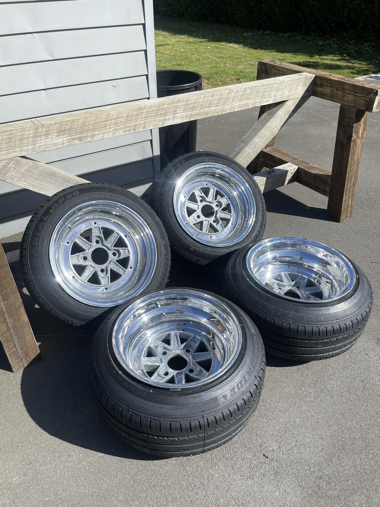
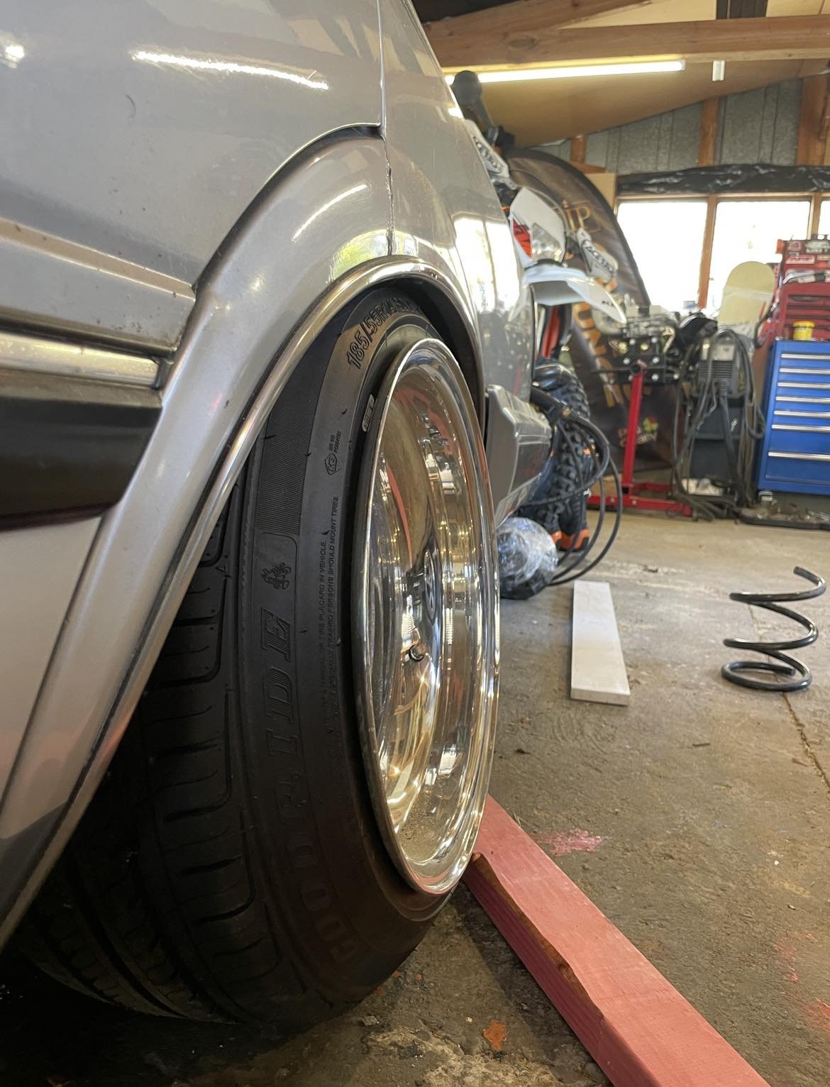
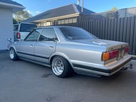
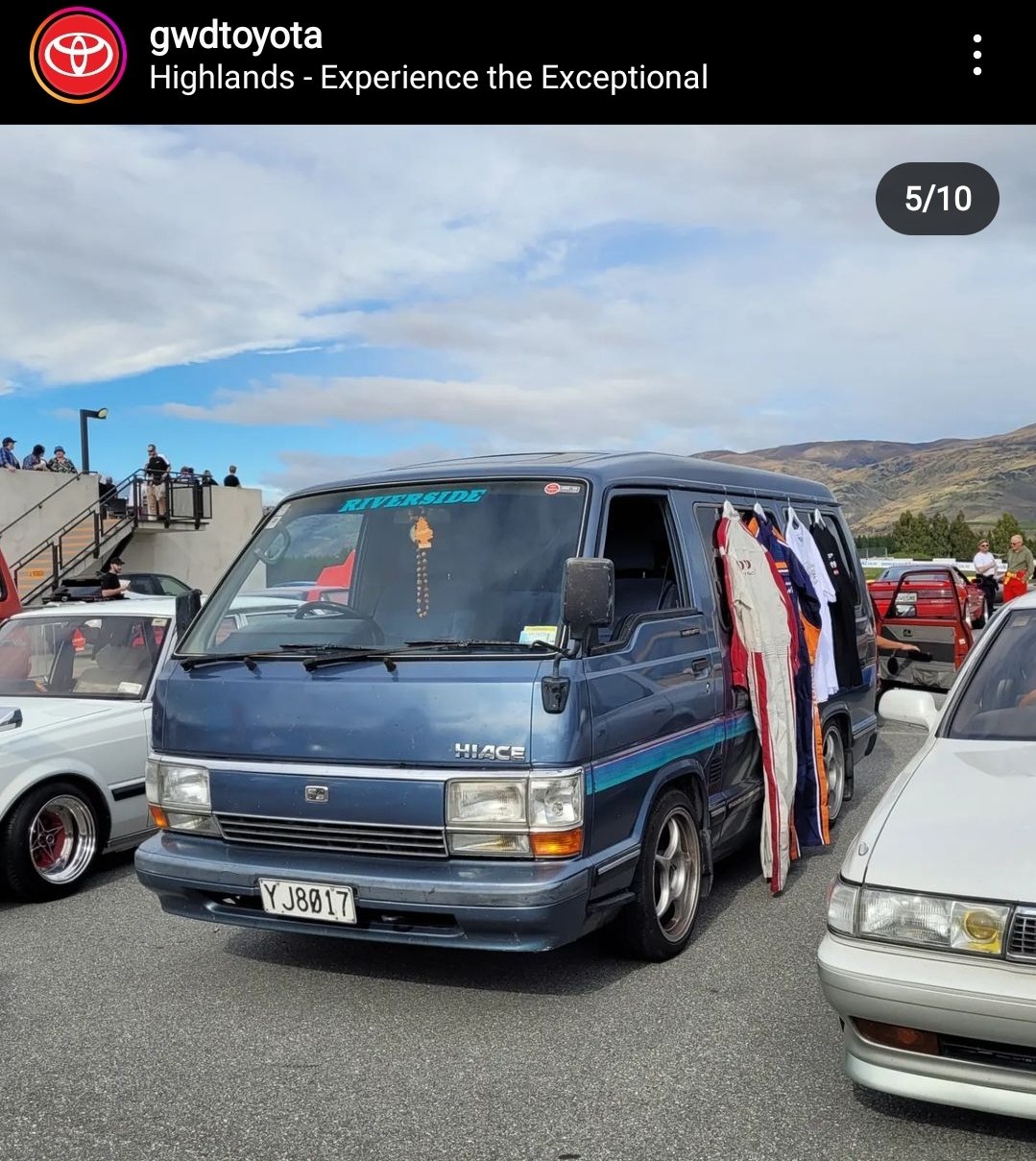
Back home in Porirua. I picked up another set of wheels that are looking pretty schmick. Recaro seats are also in after drilling one hole in each of the factory Toyota runners. Exhaust fell off on the way to Shannon but easily fixed with tie wire.
14 points
-
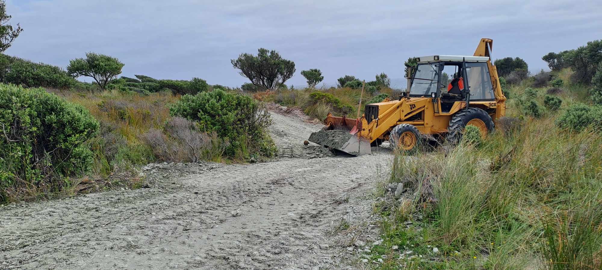
I spent most of the weekend carting schist and extending the driveway. The JCB is finally operational but oh lord it's slow and noisy. Still much better than a spade and a wheelbarrow
10 points
-
A bit of dust on the camera
9 points
-
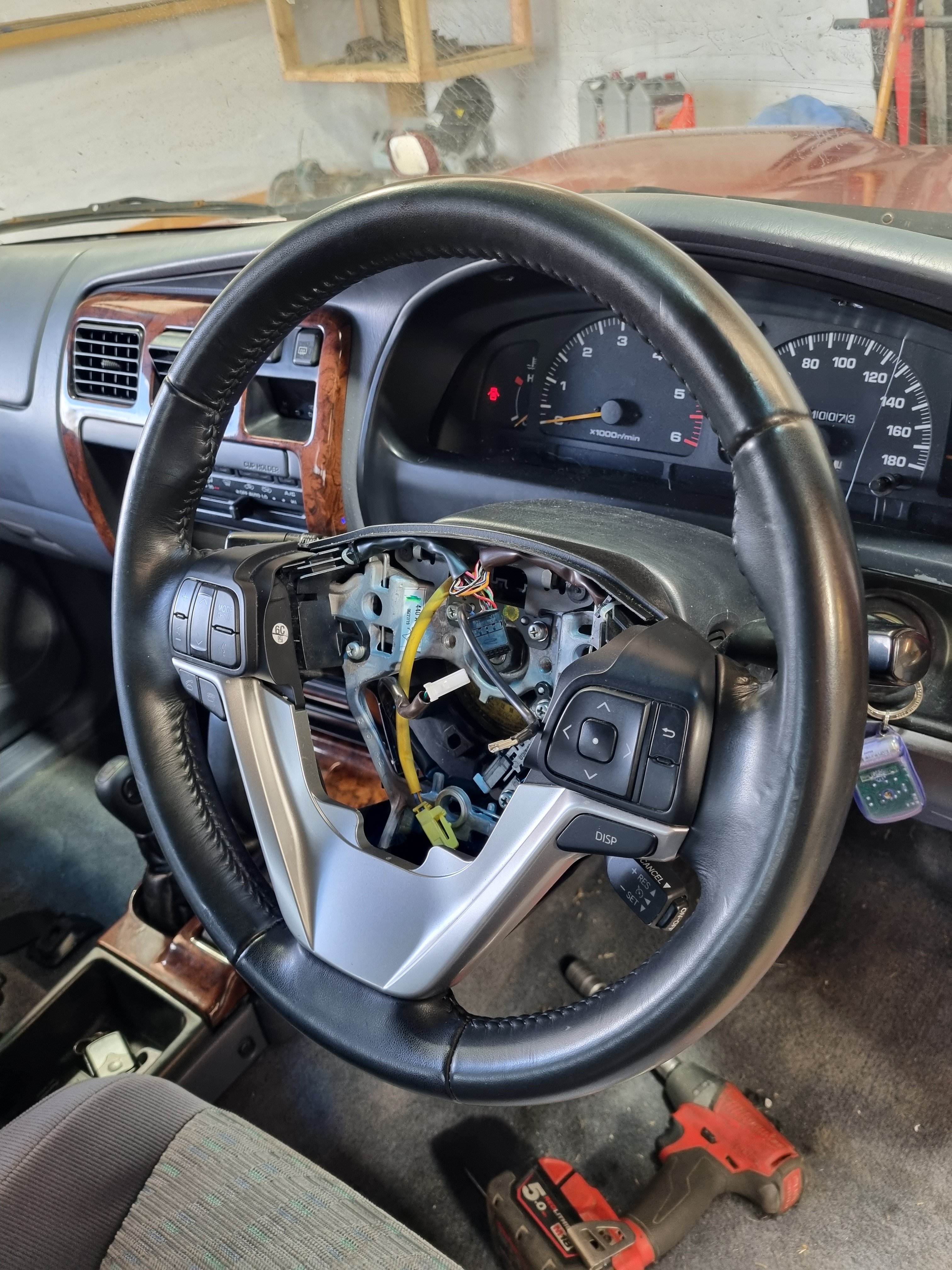
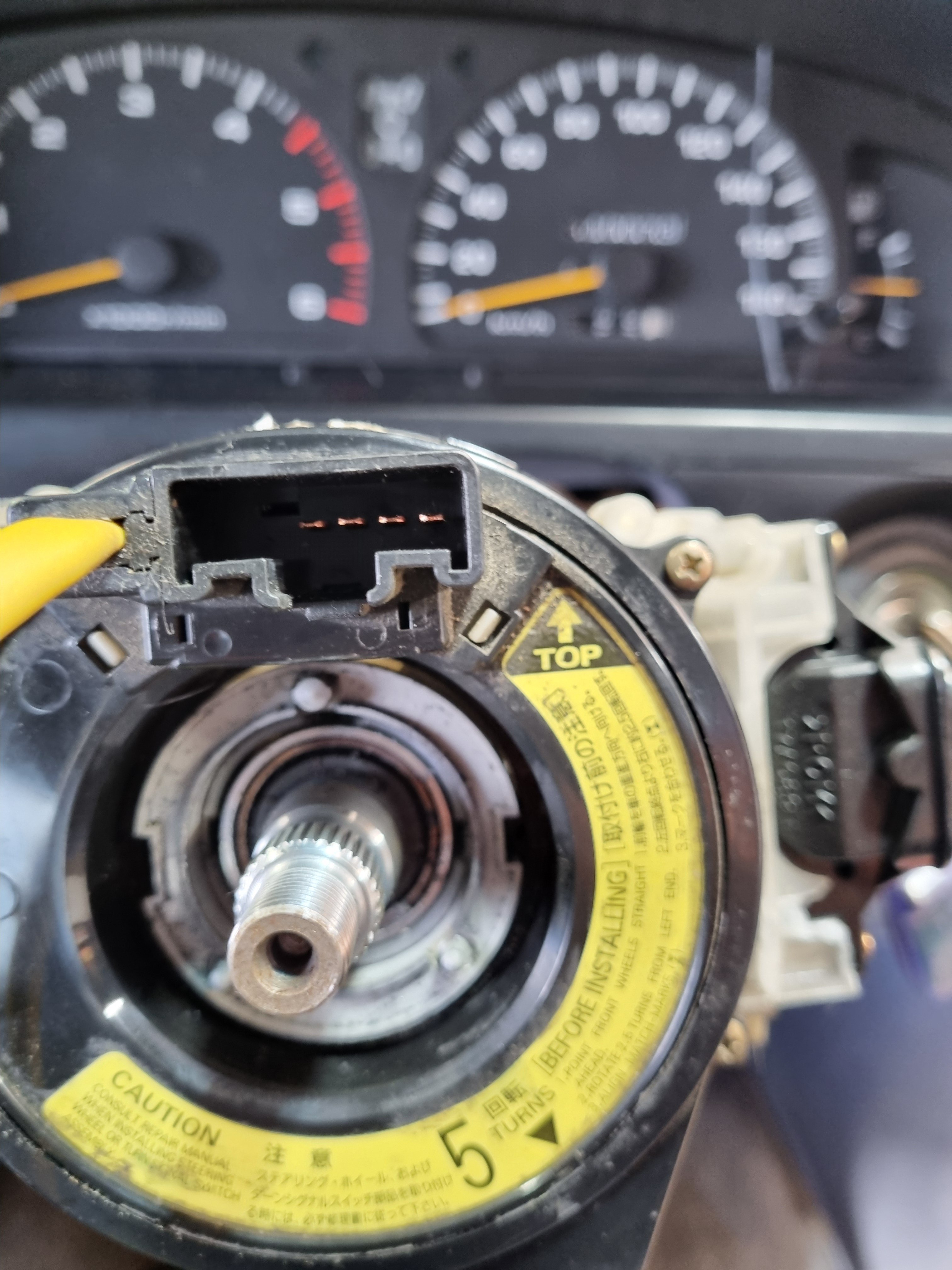
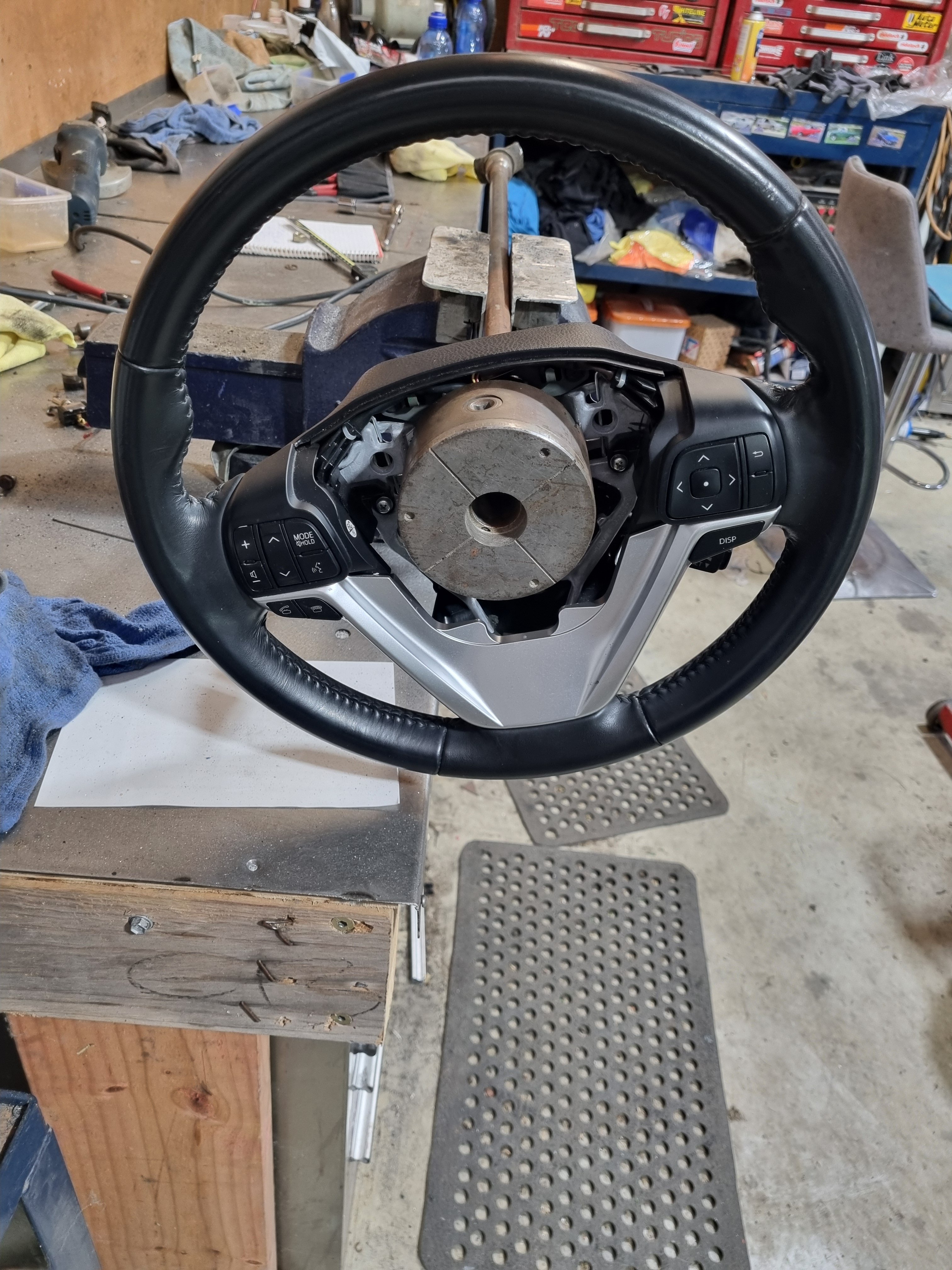
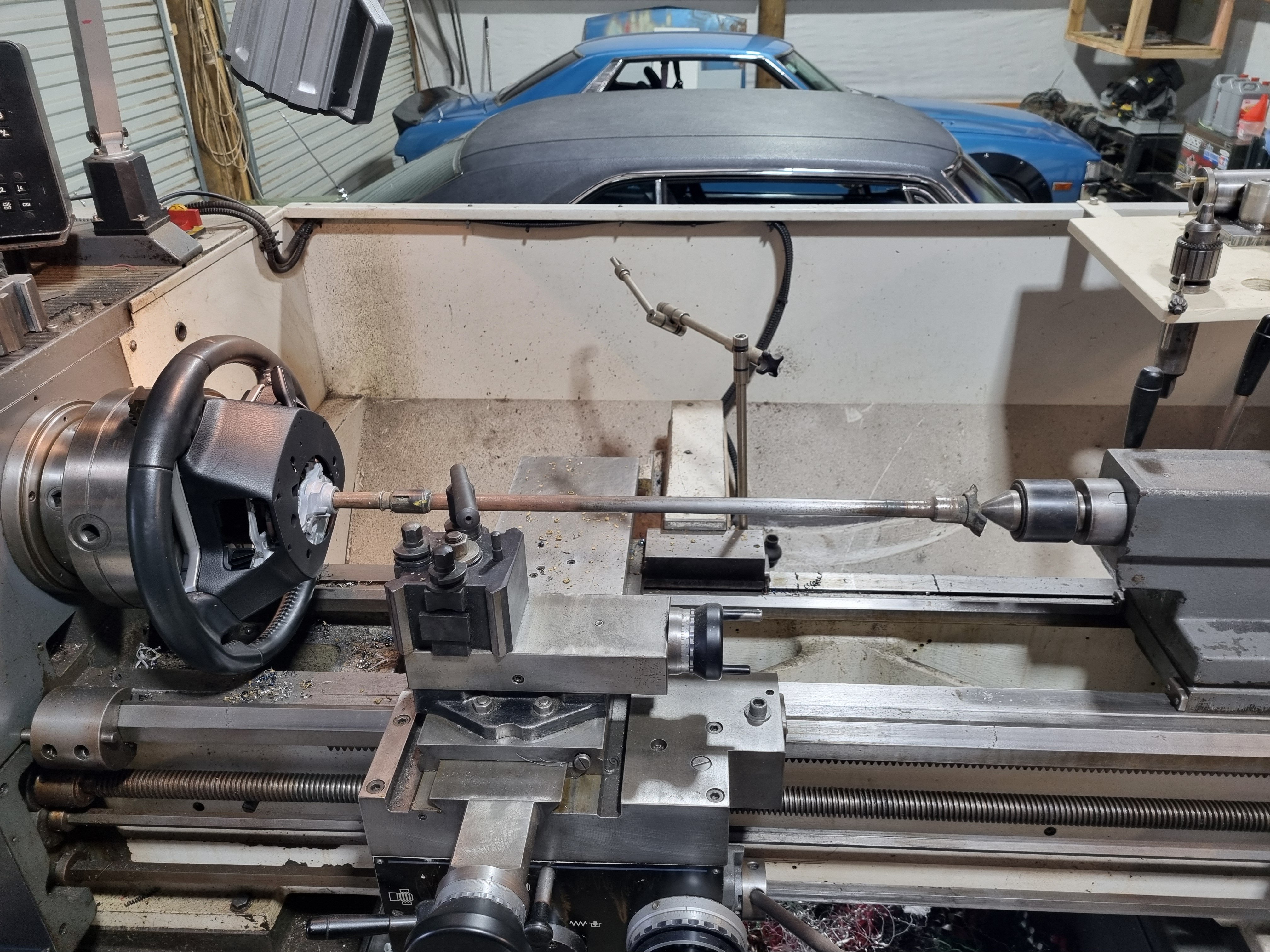
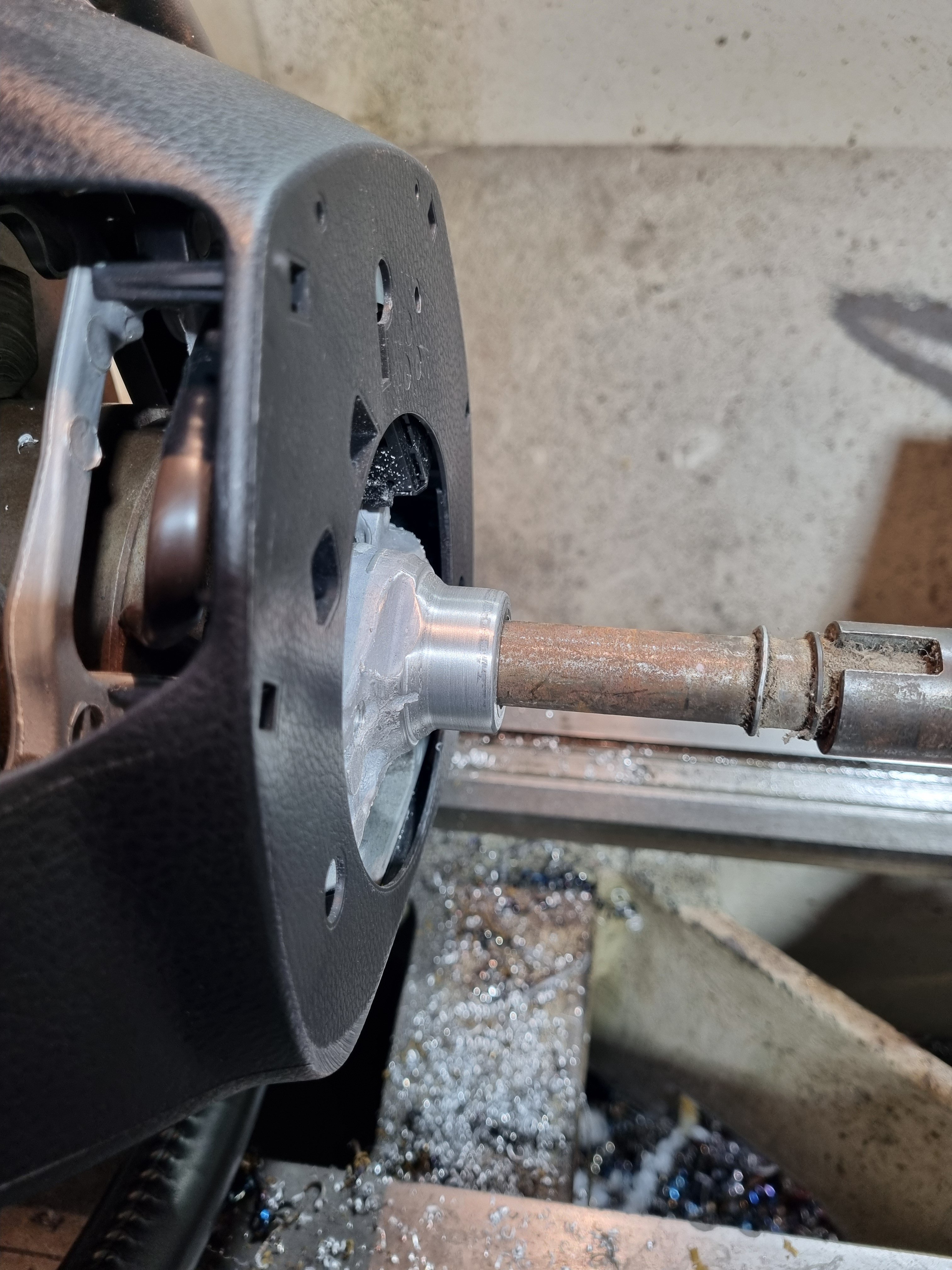
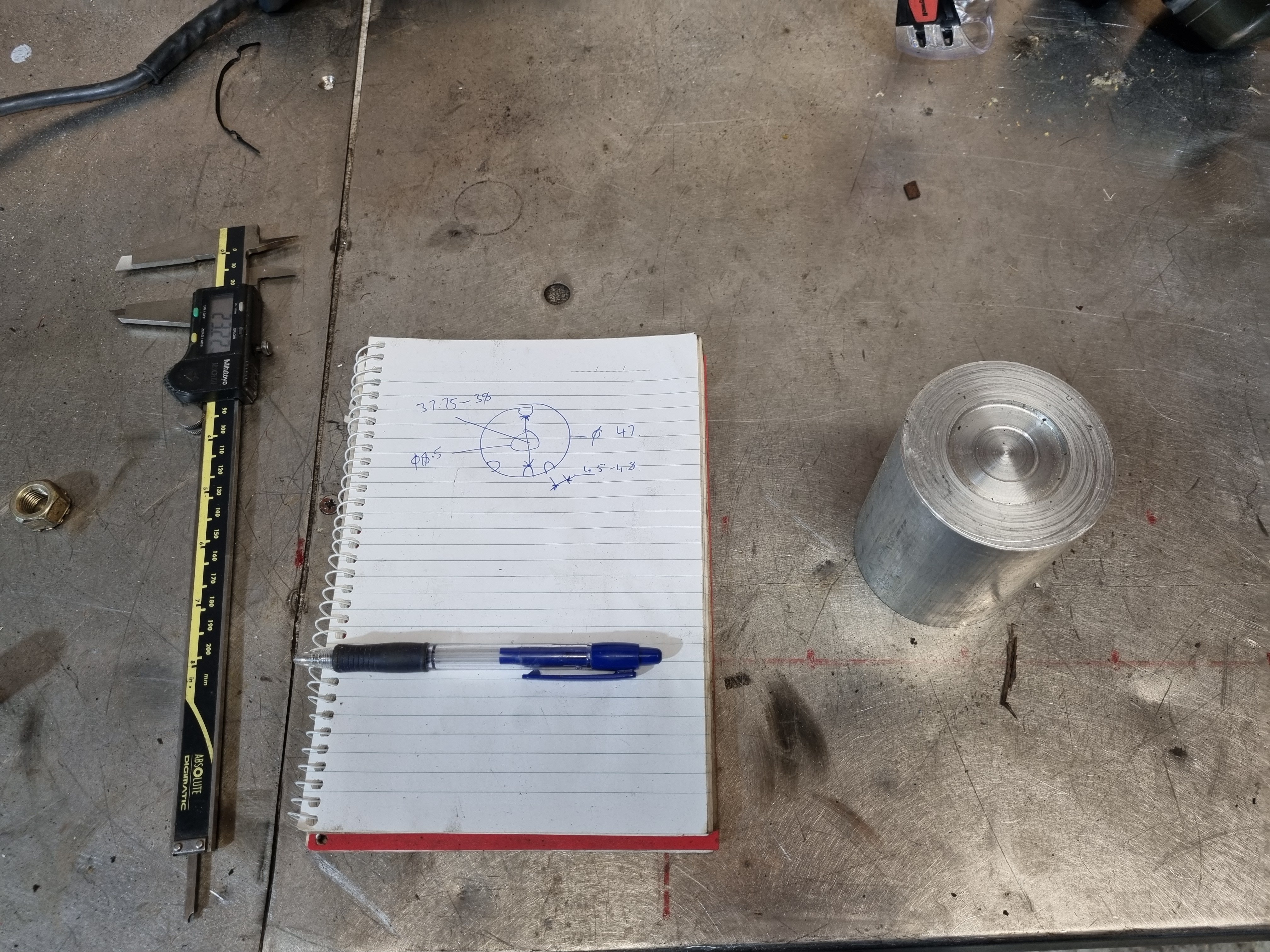
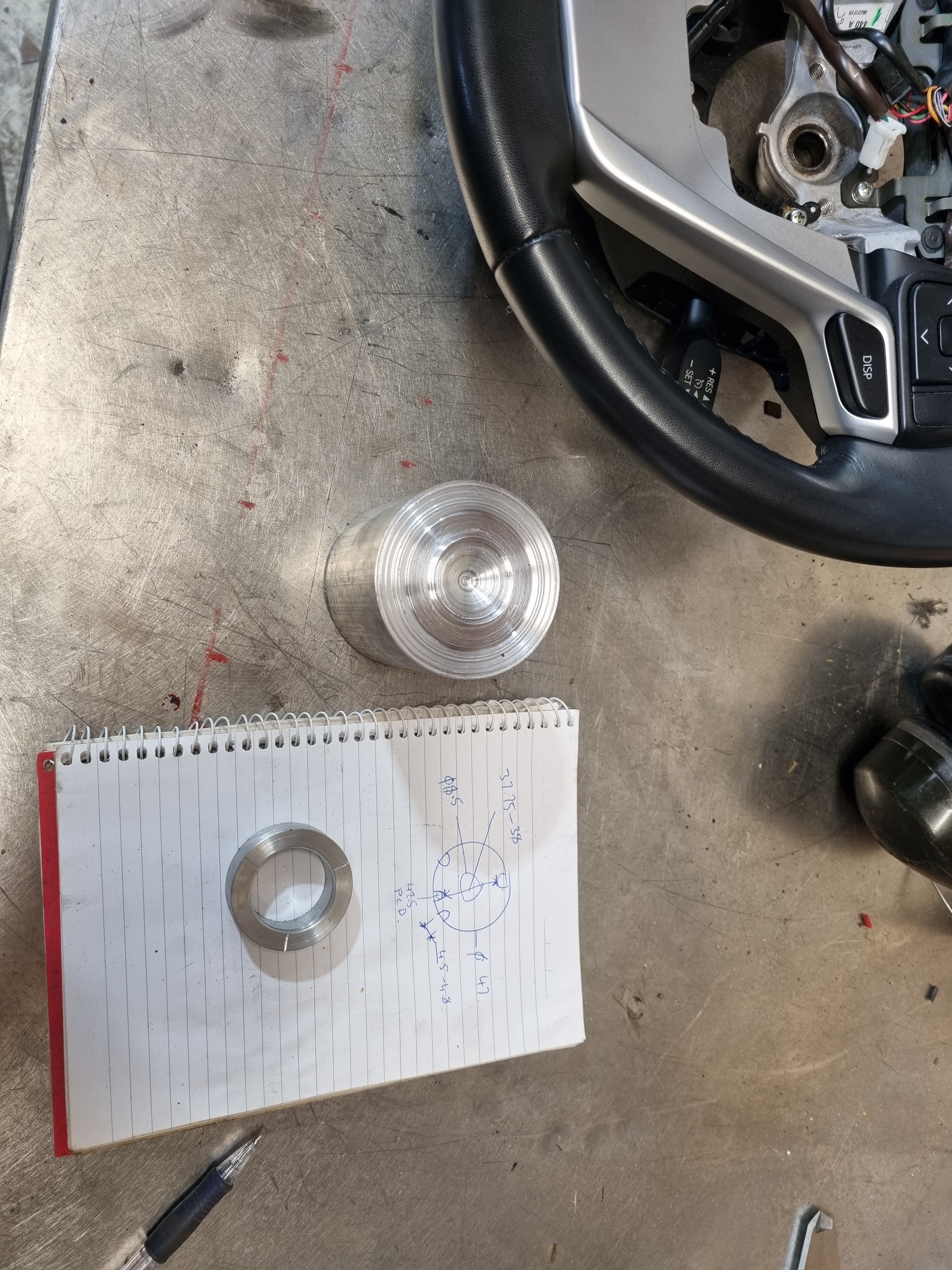
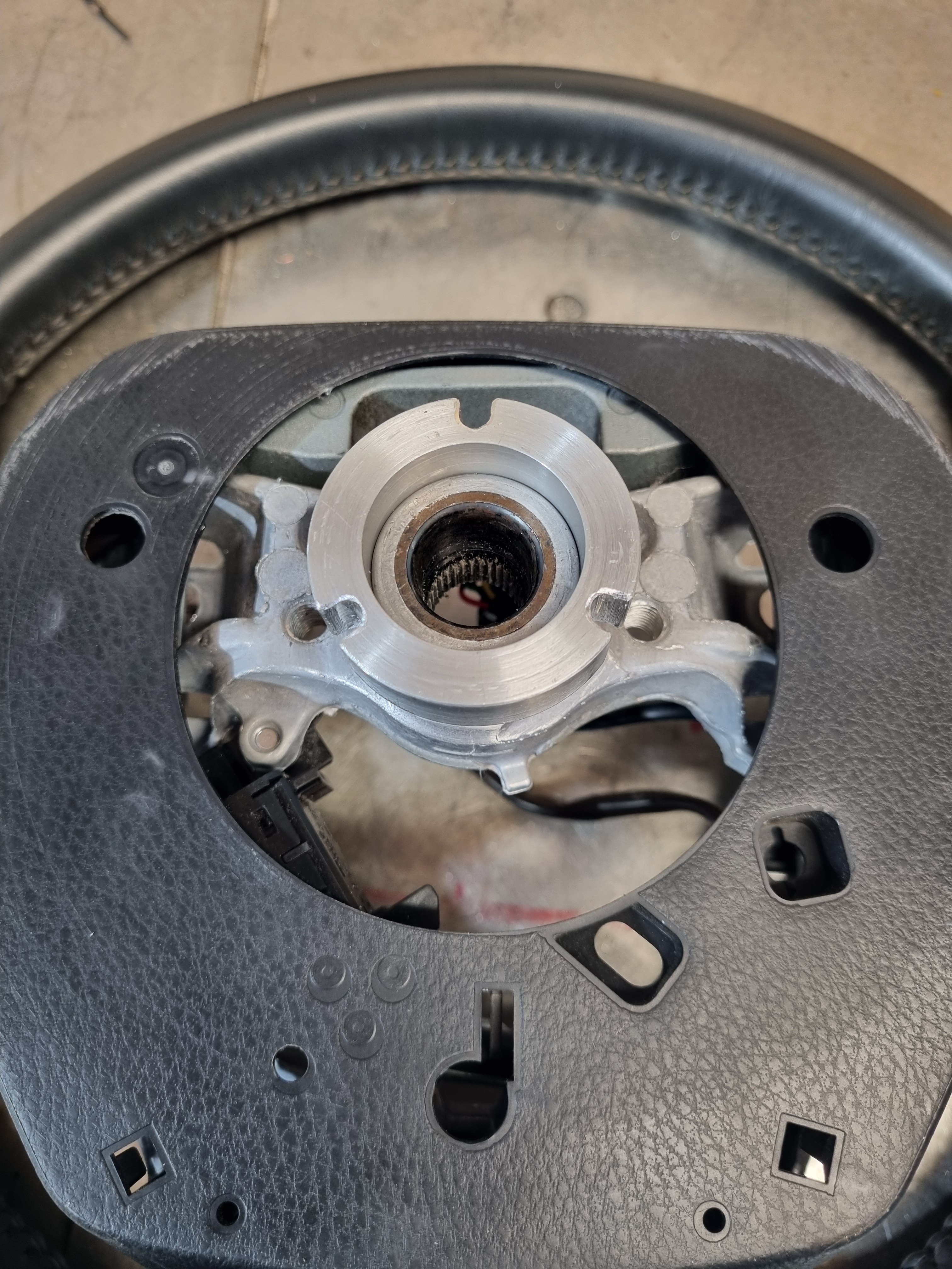
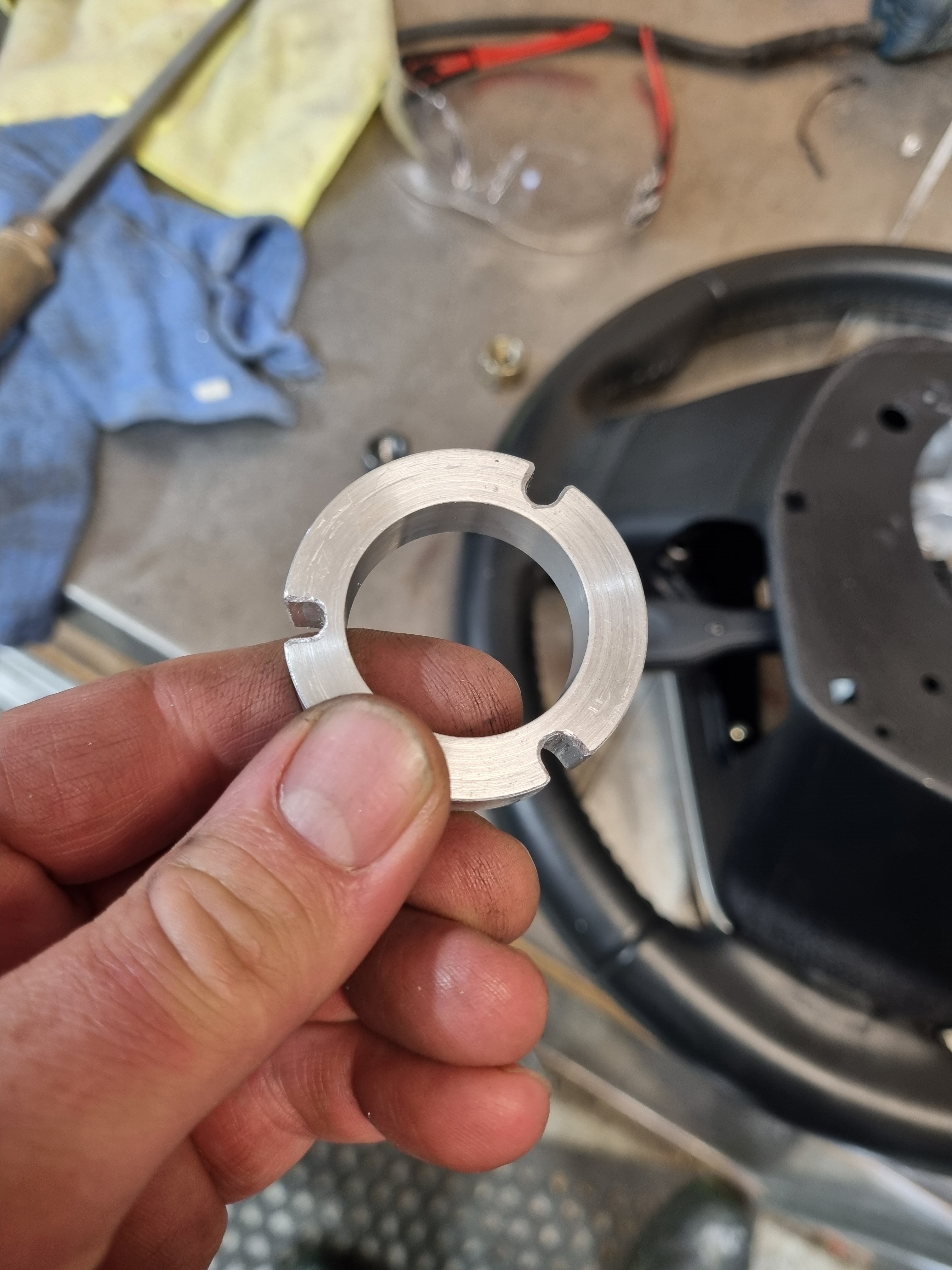
Story time/ going down the rabbit hole. The issue- I never did any homework at all when it came to buying this blaupunkt head unit. If I had of I would have very quickly been made aware of how crap it is. Is unusable as far as changing the volume, shipping tracks or doing anything. Its physically impossible to change the volume accurately, and most of the time is not possible at all. Totally my fault for not checking a single review or anything. So, present day me (well yesterday me actually) was yarning to Nick the sparky about steering wheel controls and clock springs and whatnot and he said "I've got a 2013 Highlander steering wheel, see it that fits" It does. I needed to make a indicator canceling wheel to adapt the new wheel to the hilux. Not super difficult, made a frankinstien rig up to machine a parallel diameter in the back of the wheel. Them made a ring that I will shrink onto the back of the wheel once I confirm its fits the truck. Then the next hurdle will be getting signals through the clock spring. It has 3 spare wires that aren't used so we can use those to send signals to the head unit. But there are probably other clock springs that will fit the truck that have more wires if we need it.
9 points
-
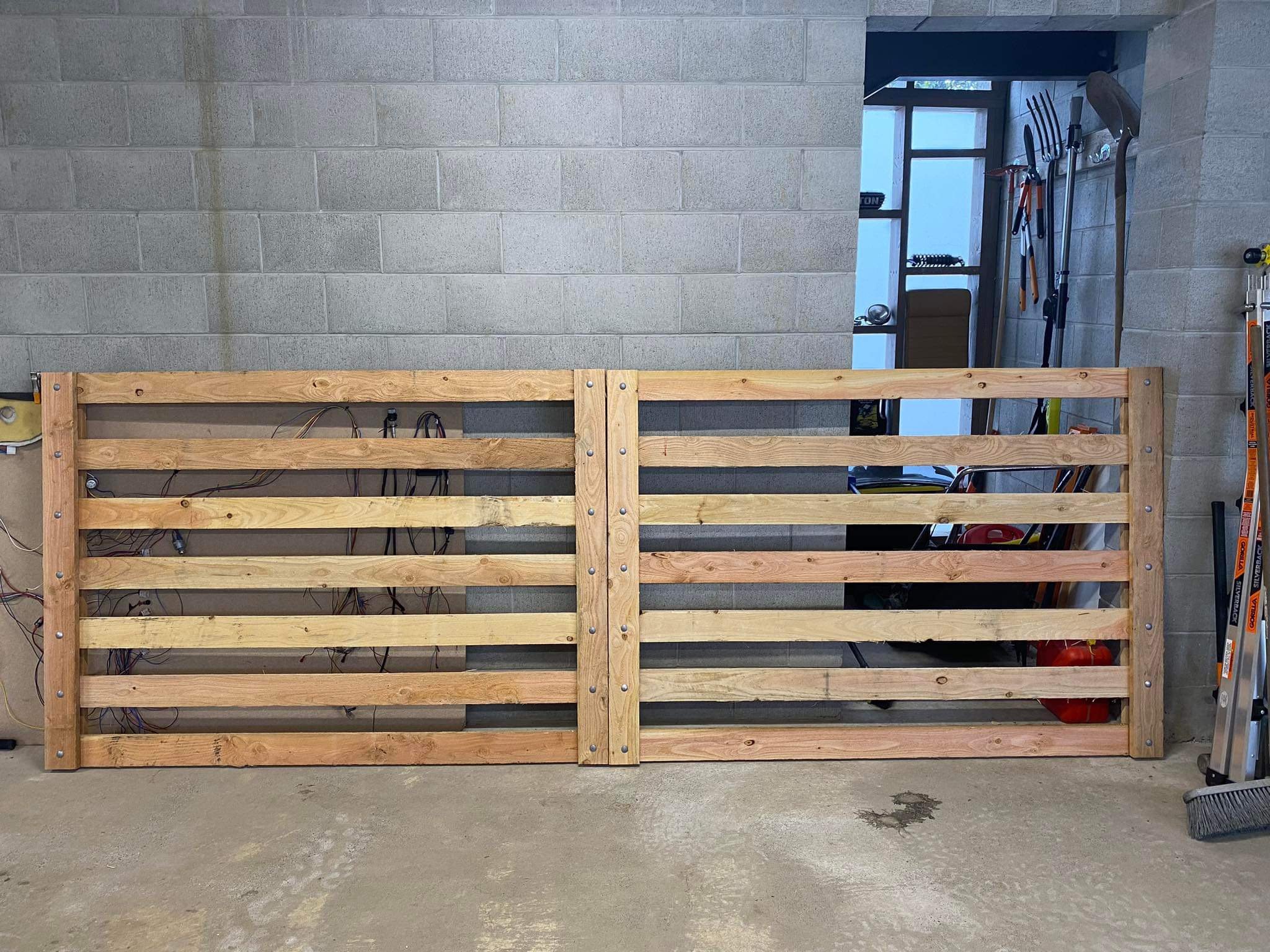
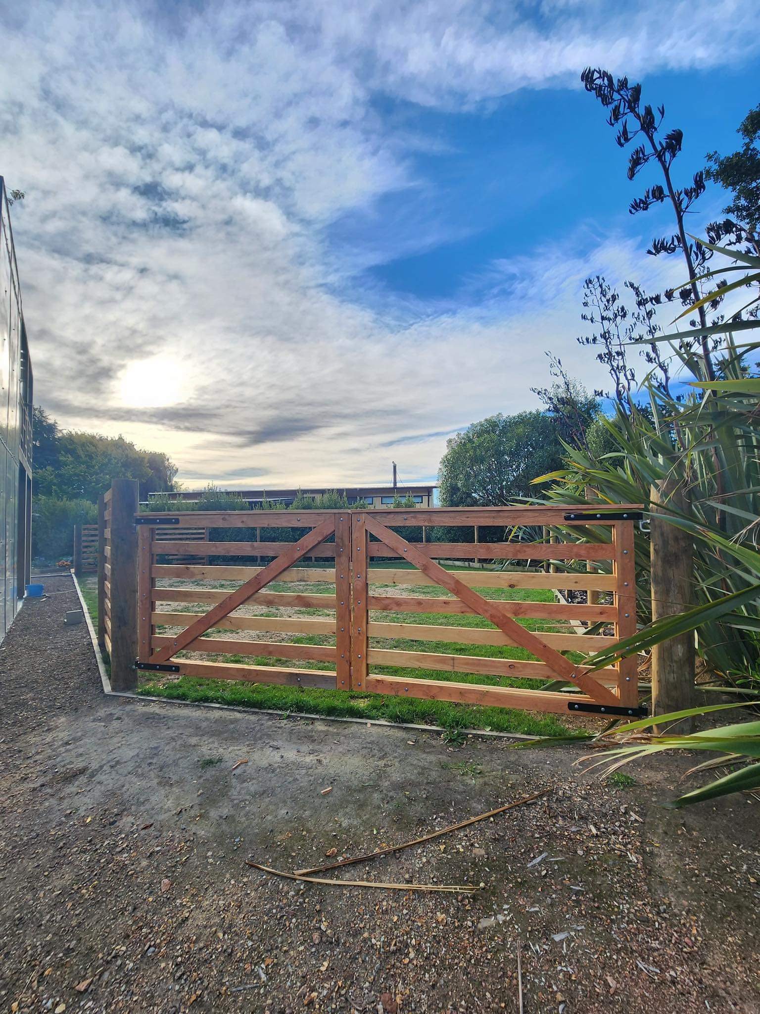
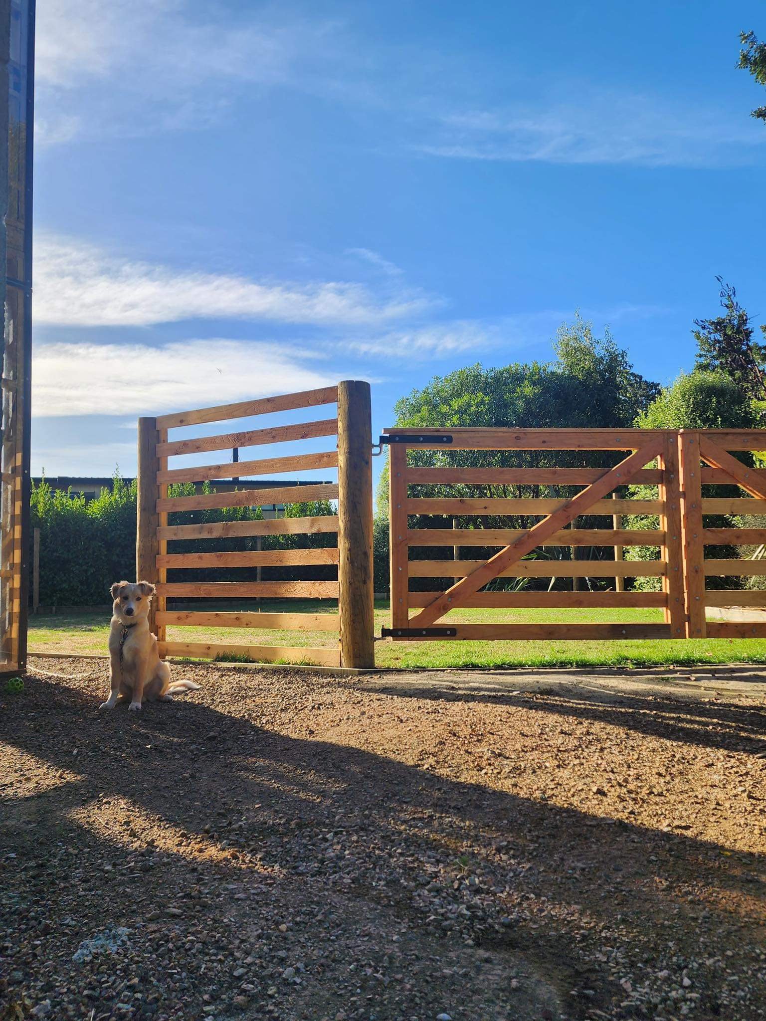
Made some gates so Finn has a nice place to hang out off the lead. Gates are 100x25 Oregon and 200mm round strainers for each gate post buried a meter per side, pretty sturdy: He was keen to show that he could still escape if he wanted to… Alcatraz it is not… yet…
8 points
-
Did a chunk of the back end wiring today, not much to see as I have tried to keep things tidy so it pretty much blends in. I tried to fit a new power plant, amazing that for the size this unit only makes one pogpower.8 points
-
7 points
-
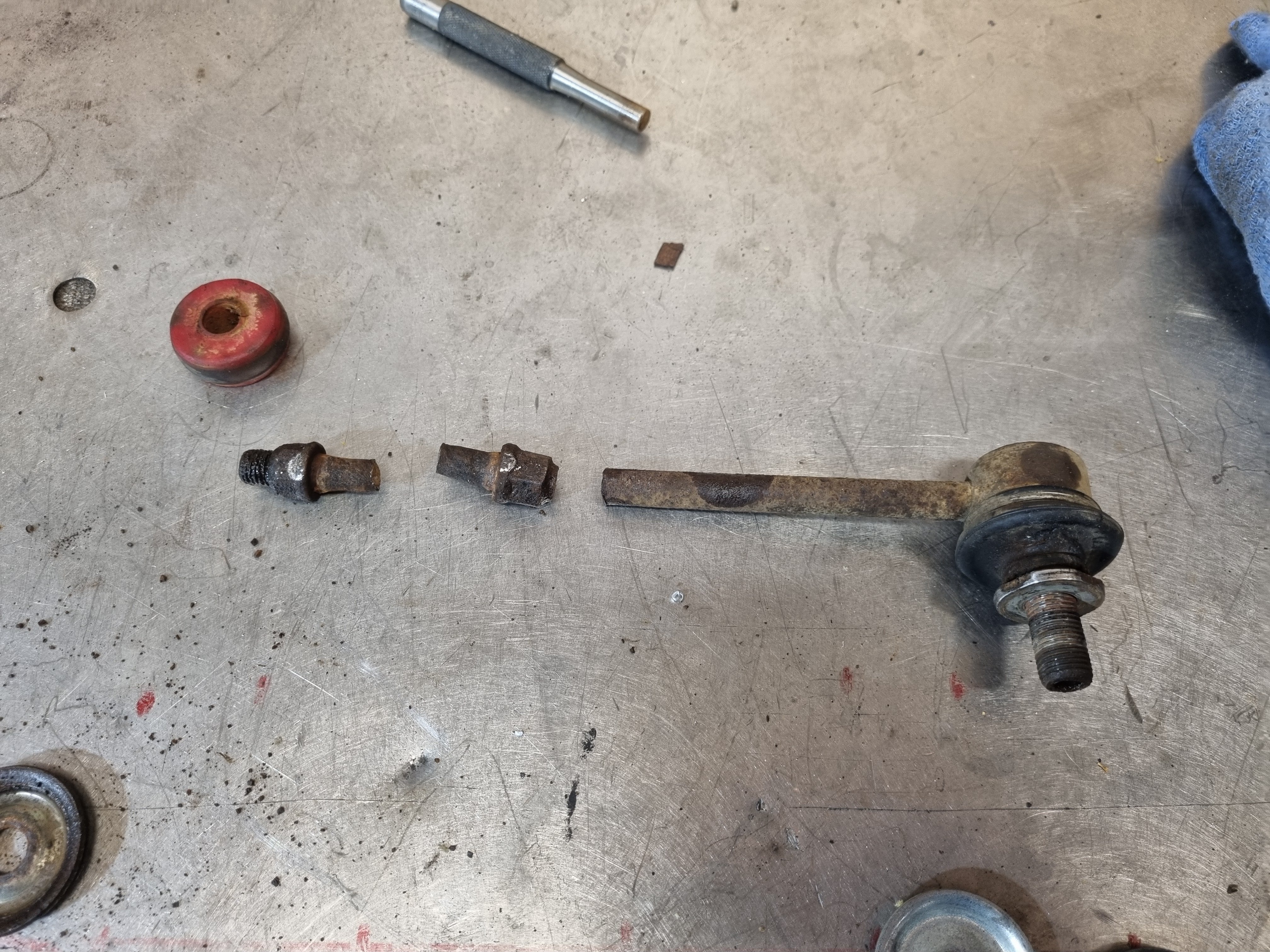
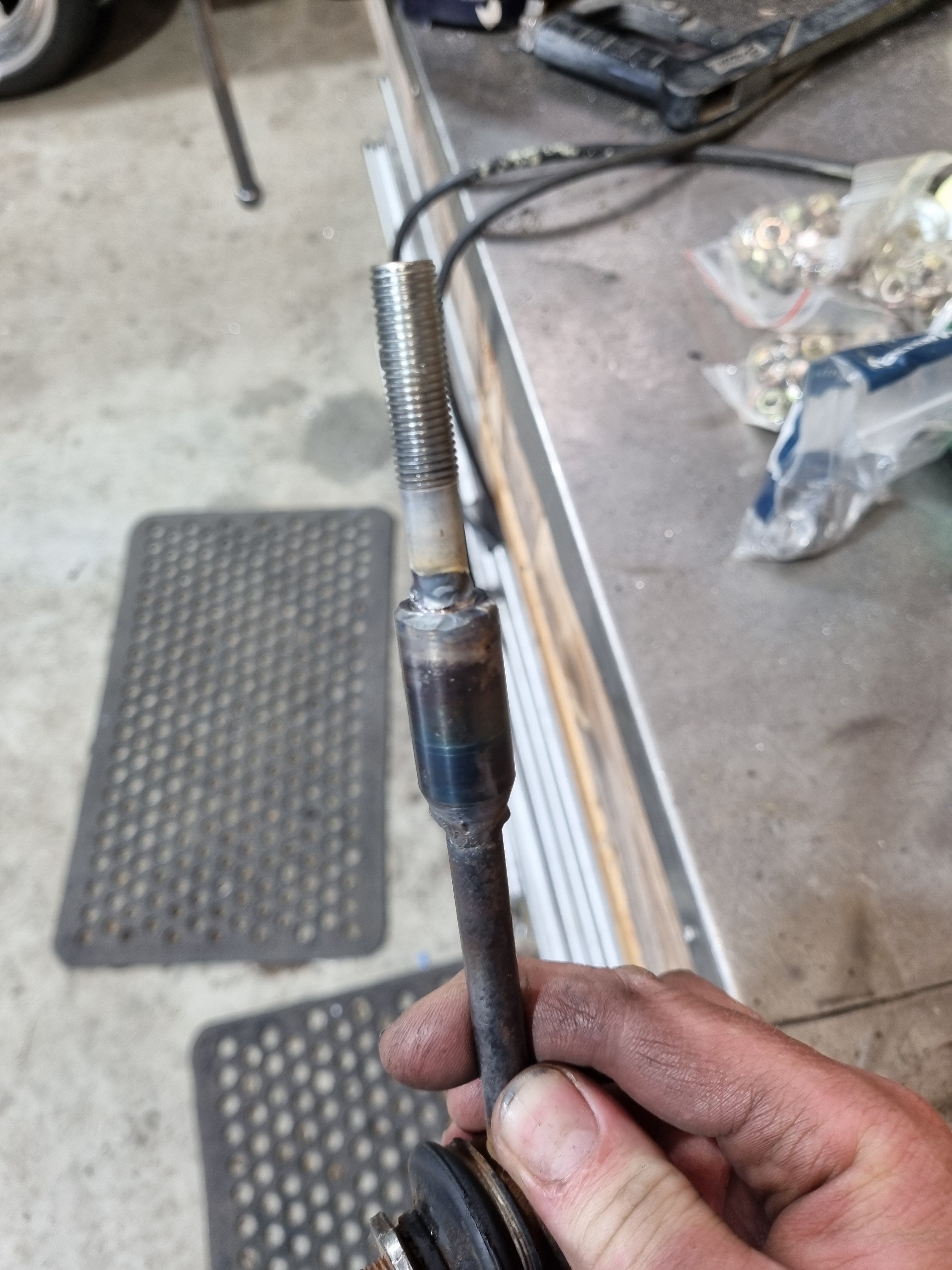
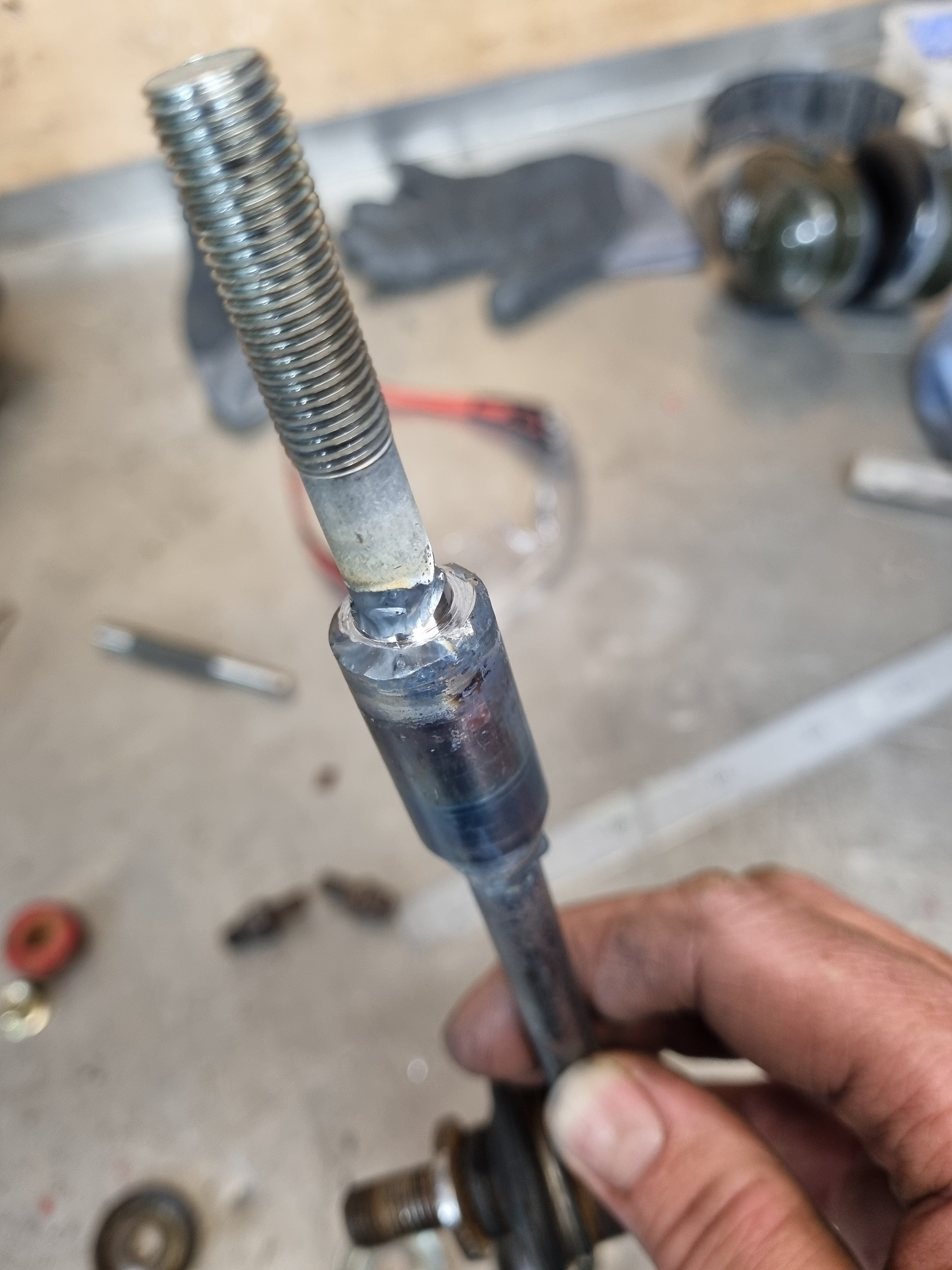
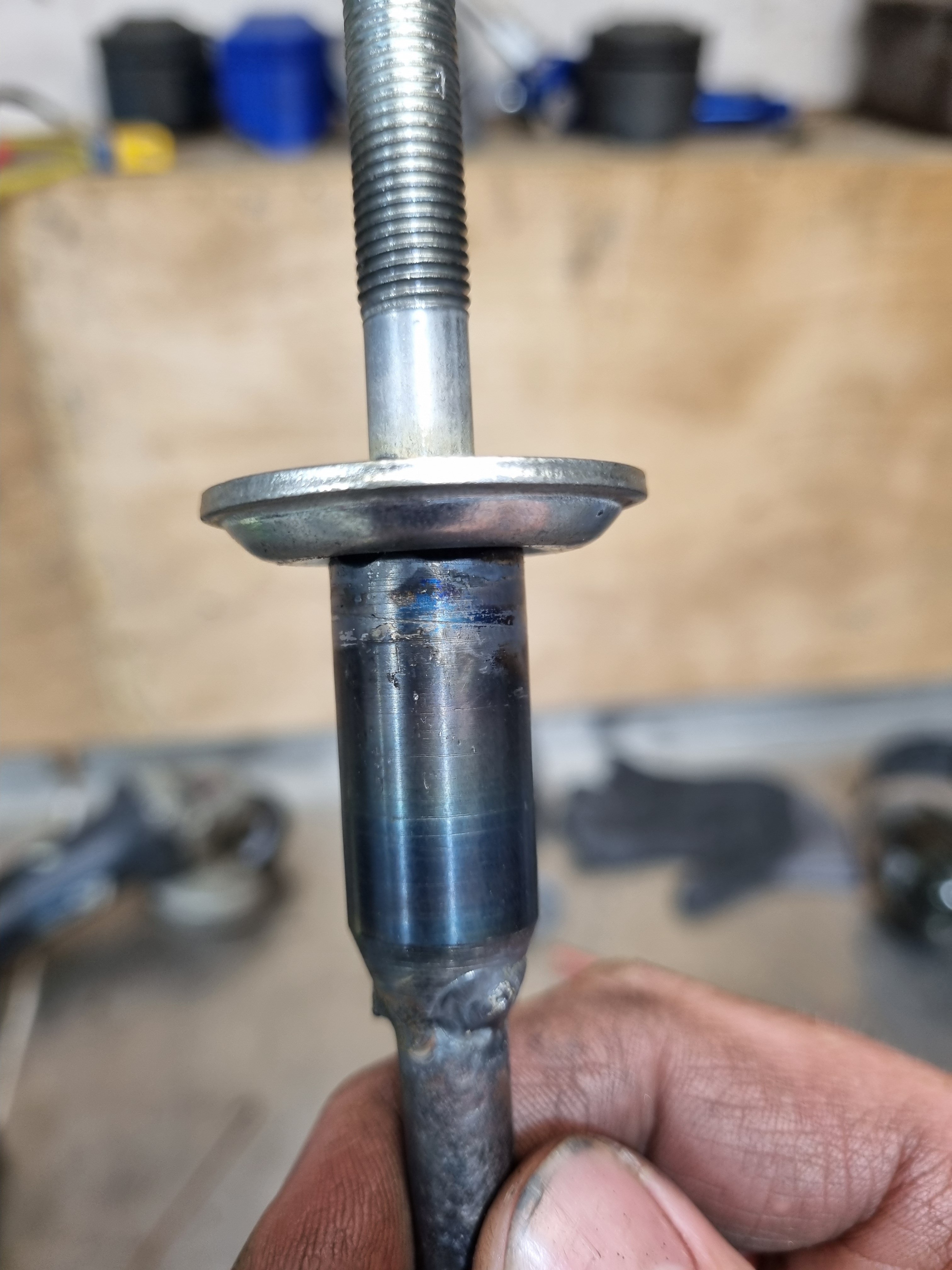
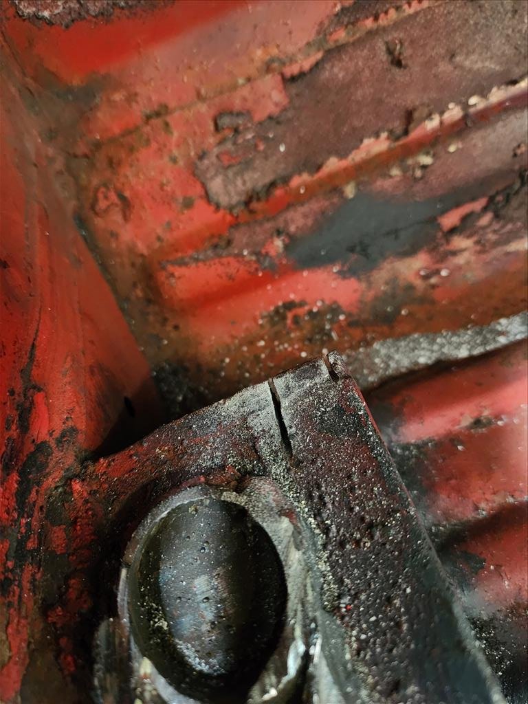
You're not going to believe this but the top bit of the swaybar link that wasn't broken broke when I tried to undo it. So I welded a new end on it.
6 points
-
Some stuff happened
5 points
-
Well its a month later and I am getting back on form, hence this effort today; Plenty of room to finish off the wiring now. There was a minor mishap during engagements, now I need to figure out which Fiat Uno that distributor is off. I'll give the donk a clean up, new oils and filter, new plugs etc. Might drop the sump to see the state of play. For some reason it has way more oil than it actually needs, not sure why.5 points
-
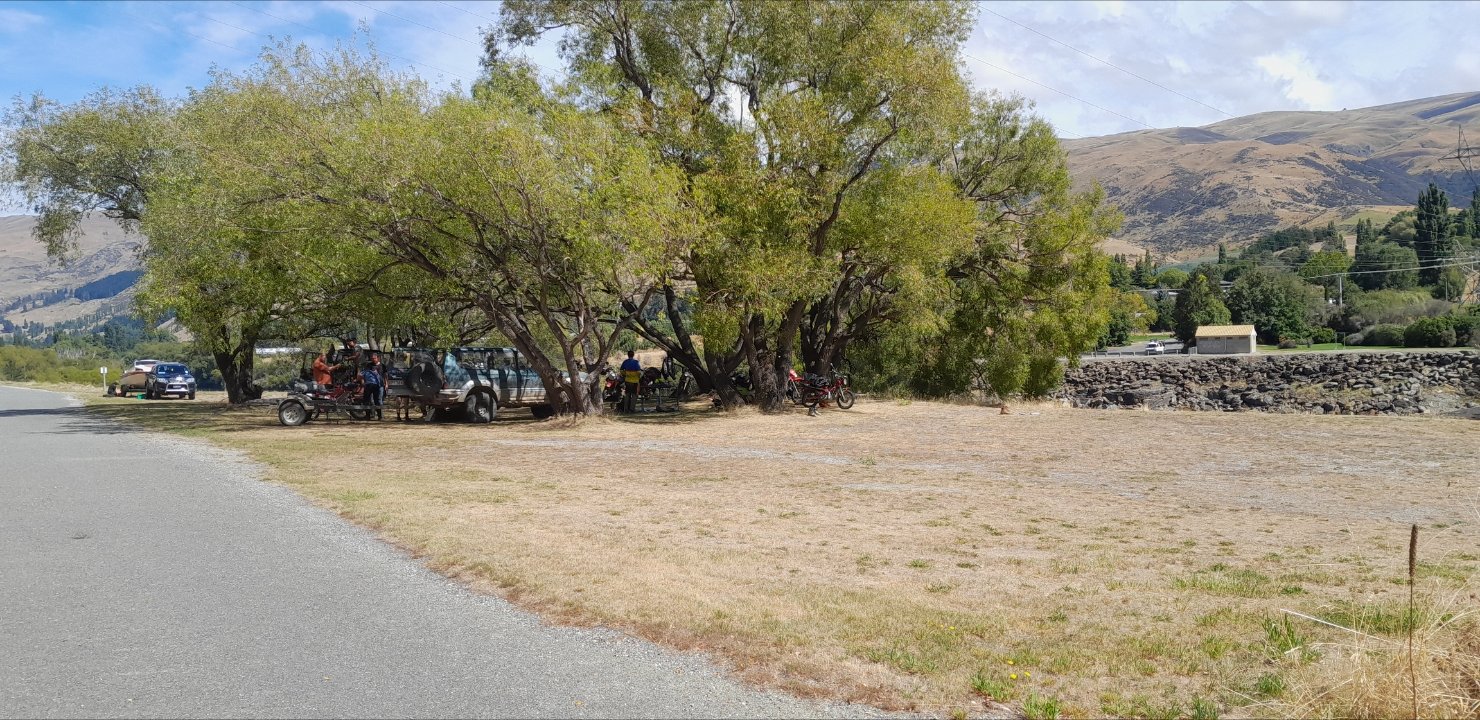
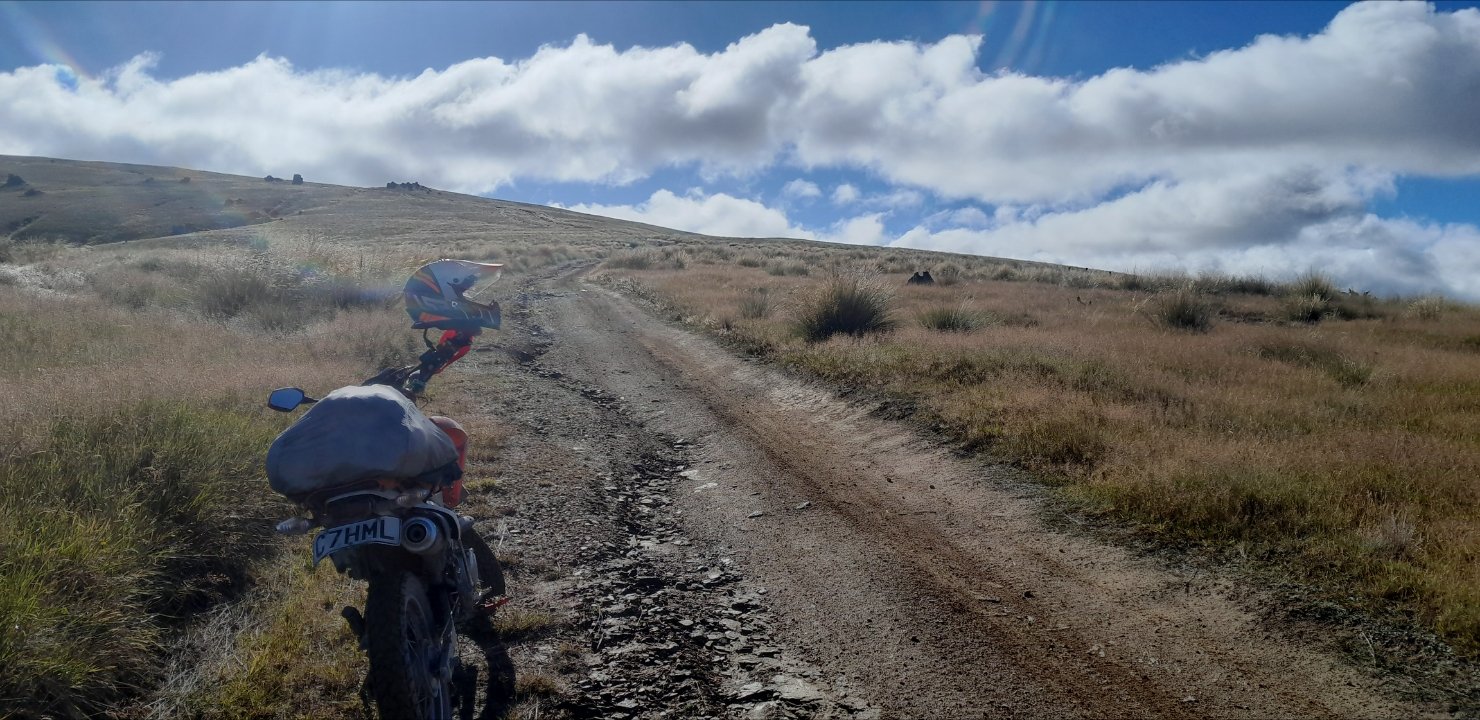
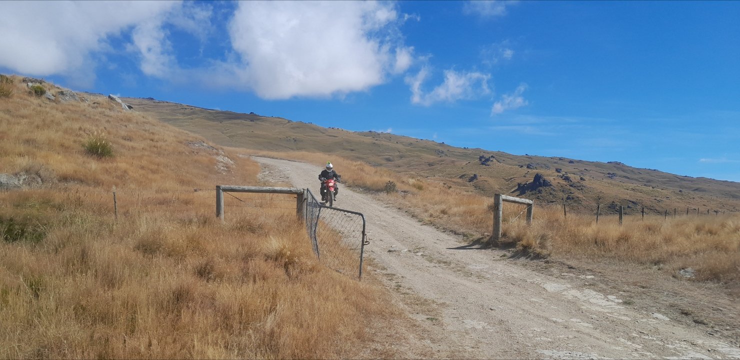
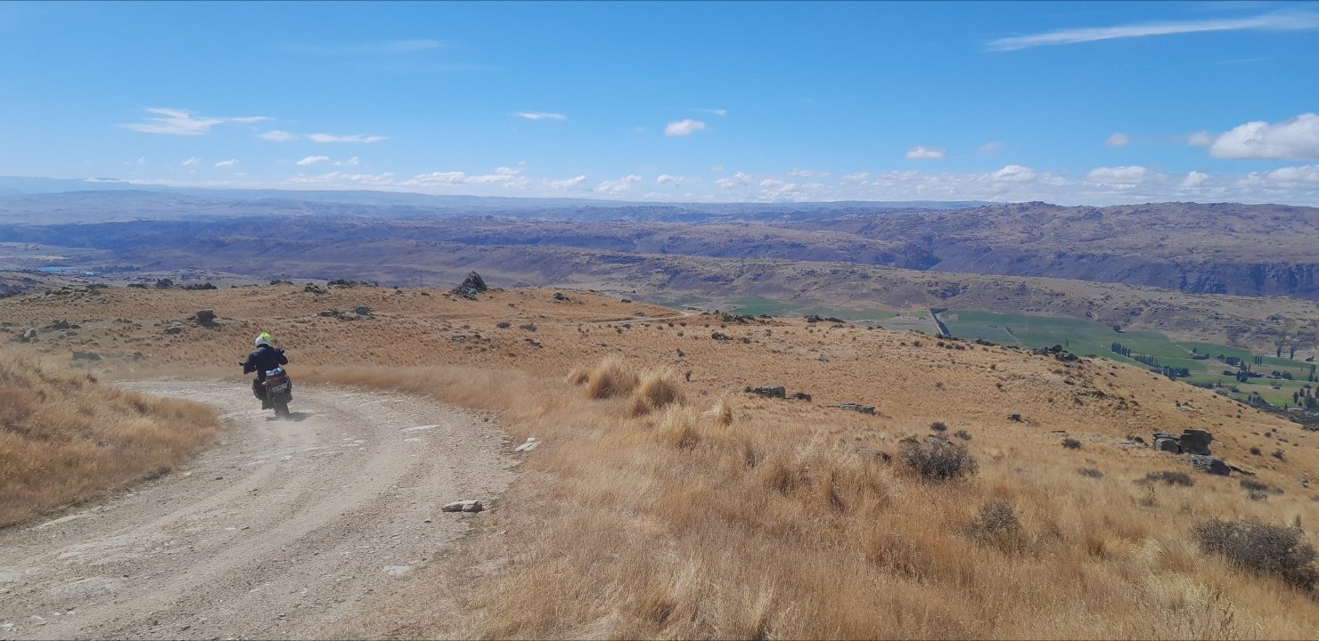
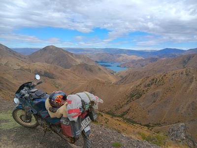
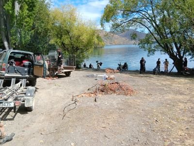
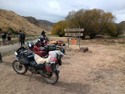
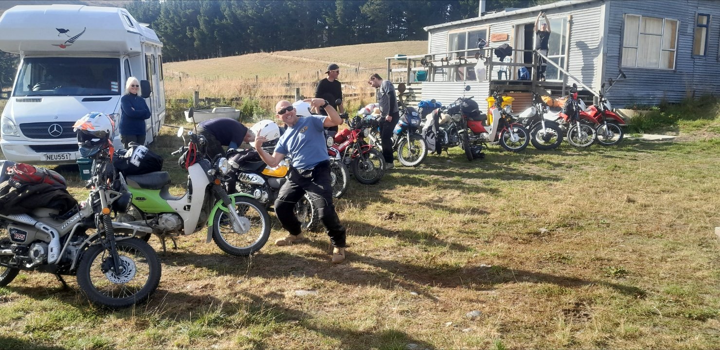
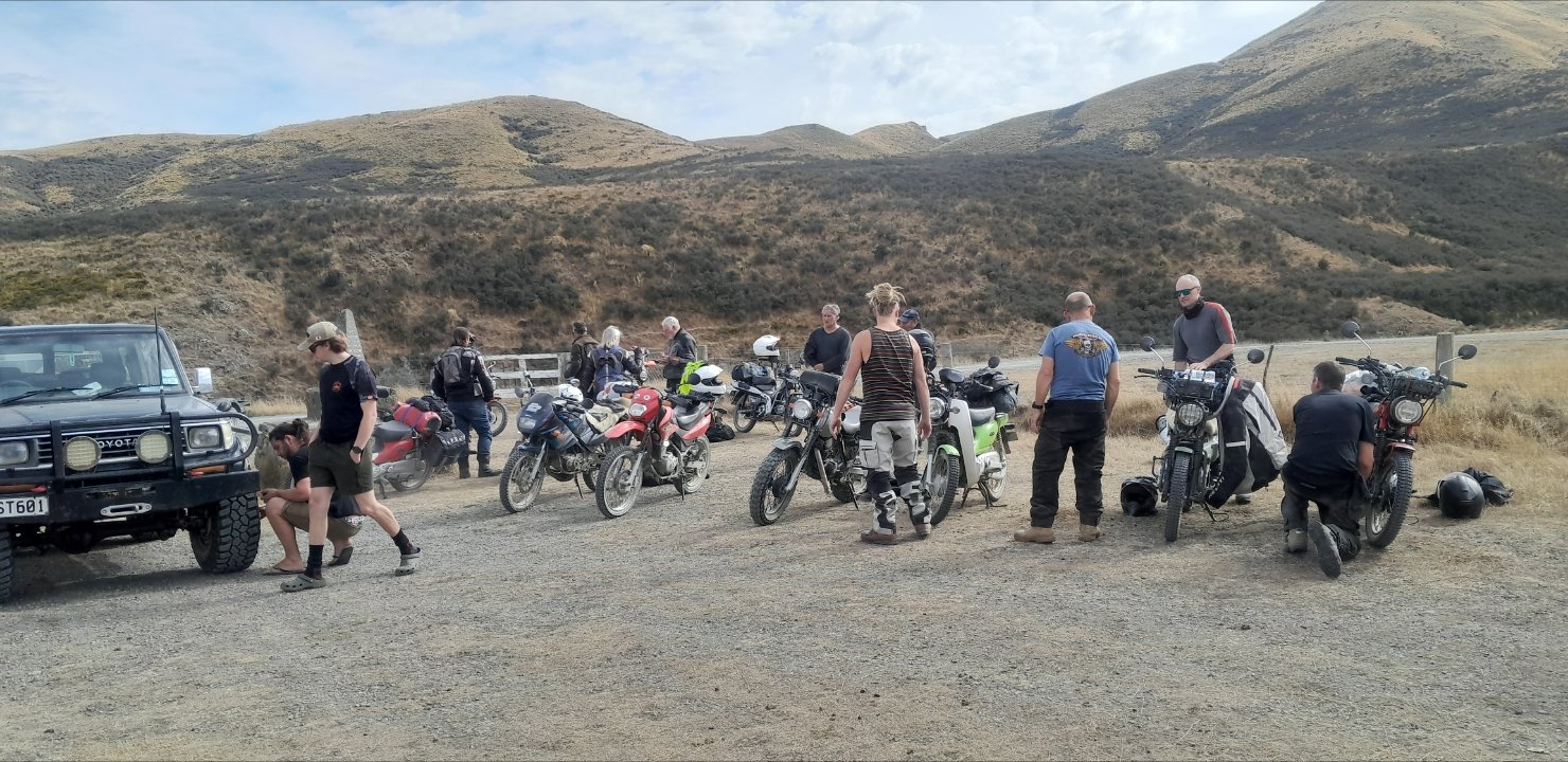
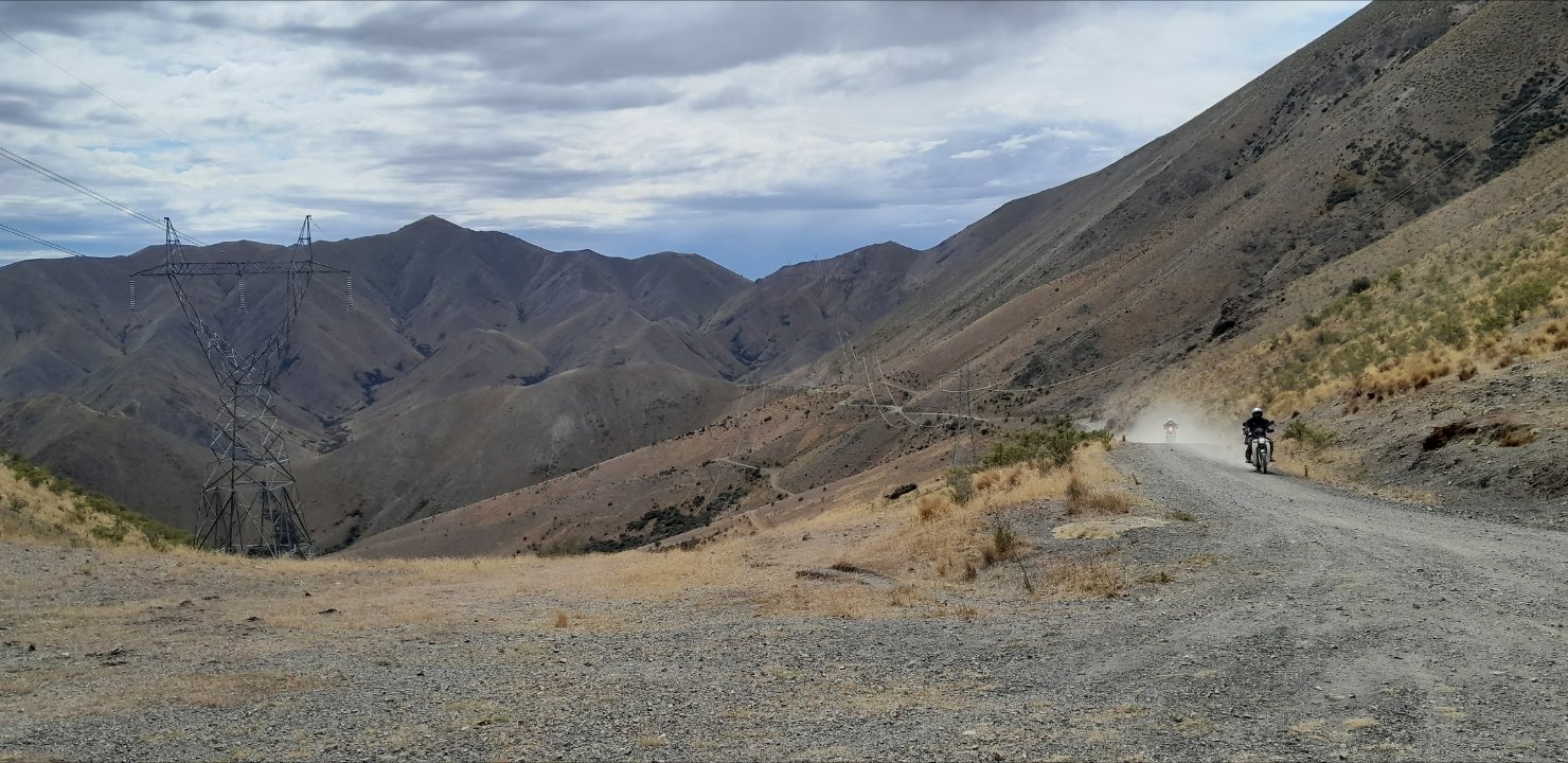
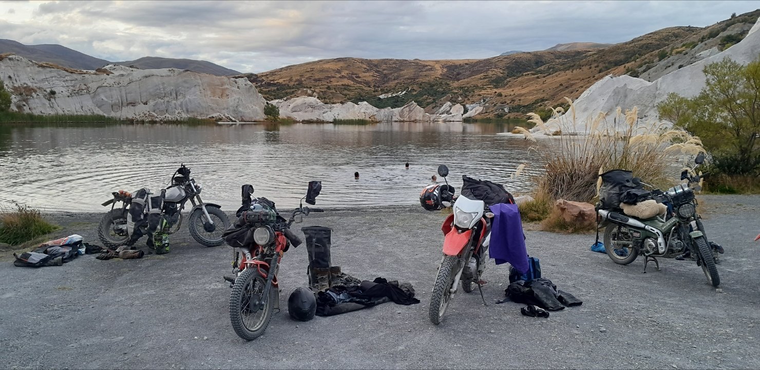
Fuck, this ride has been epic! Bbqs, beers, and small bikes. Plus pub feeds. Nothing short of a pleasure to have @TimShadboltfan27 joing us for part of the journey. Also quite delightful to get to see @Truenotchfor a beer and a sharn at the riversdale pub last night. Thus far the weather has co-operated. And we've had nobody injured/very low boke attrition rate. (Besides @holdenman cable, @NZChaddy has suffered two snakebite flatties. I wish this ride could never end.......4 points
-
Need to find a tidy console so i can fit some sounds, otherwise buttoning up a few more pieces, to make it look clean in the meantime, will throw some covers on the seats cause they need trimming Ordered belts but I think they've sent me the wrong ones, was really hoping to do a wof this week, oh well will relax and just get it sorted
4 points
-
Chuffed how it came out. It's not a show car paint job by any means but it's what I wanted. Still has some dents and dings as I wasn't paying for a full panel job haha. Needs lowering ASAP, have a spare set of leaves I need to do reset.
4 points
-
Damn I am pissed off. My new clutch cable went tight after about 20kms so only used it to stop and take off then checked it at the lunch stop and was going to take it off but found that when I pulled the cable to get it out of the handle the inner protection pulled out the end, no more clutch so made the call to return to Farlie and go home at least I got to enjoy 1 part of the ride. Have Fun.
4 points
-
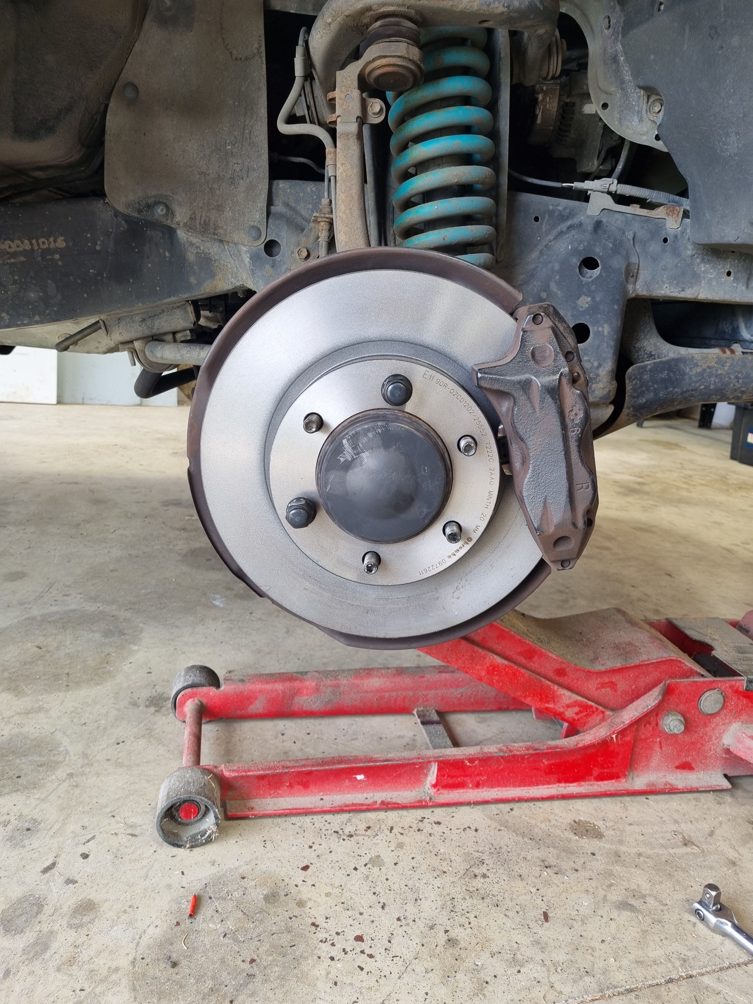
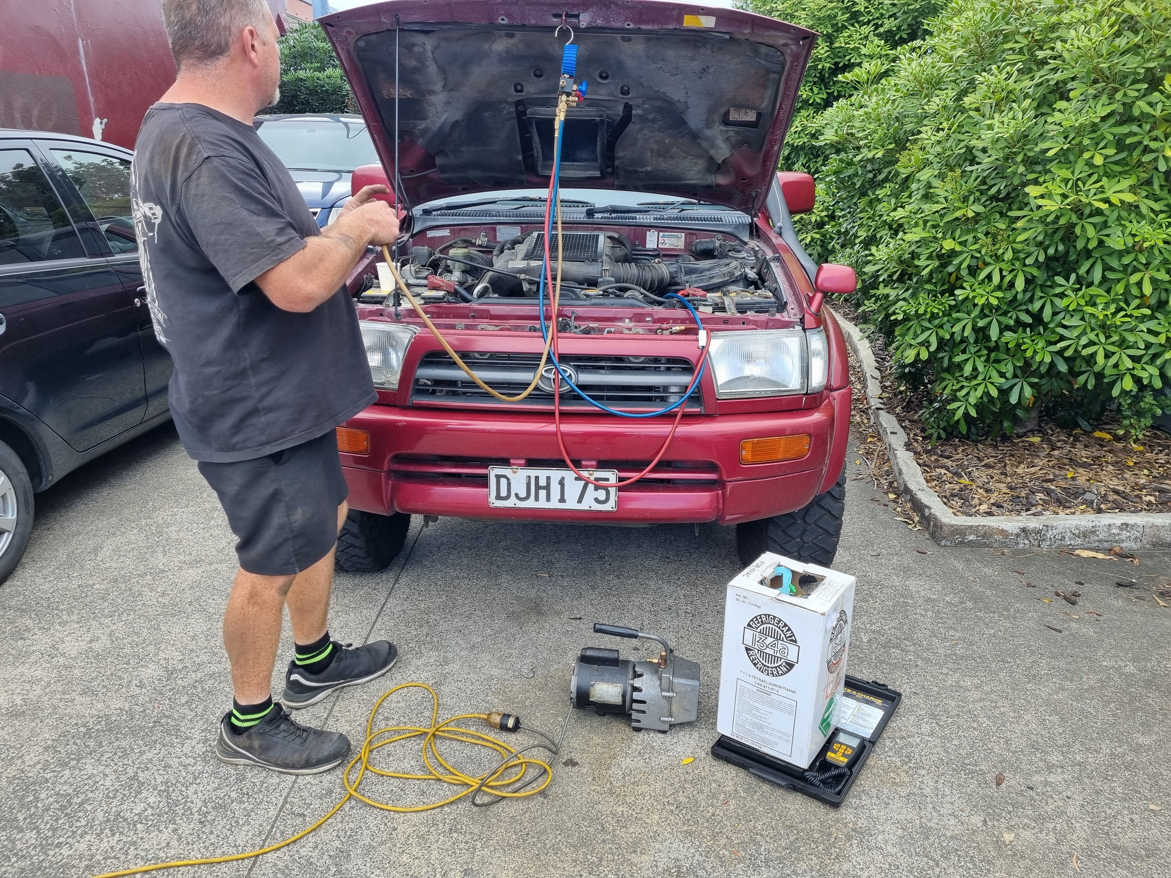
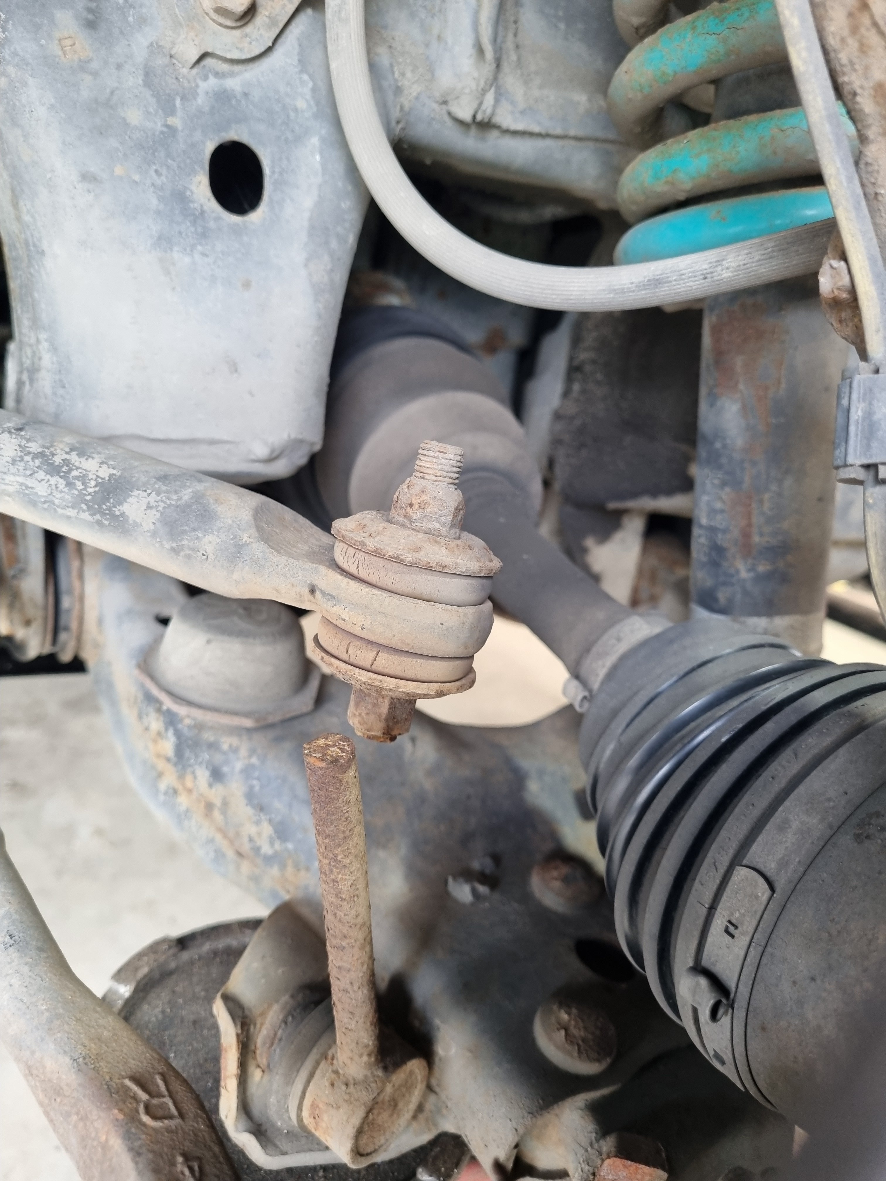
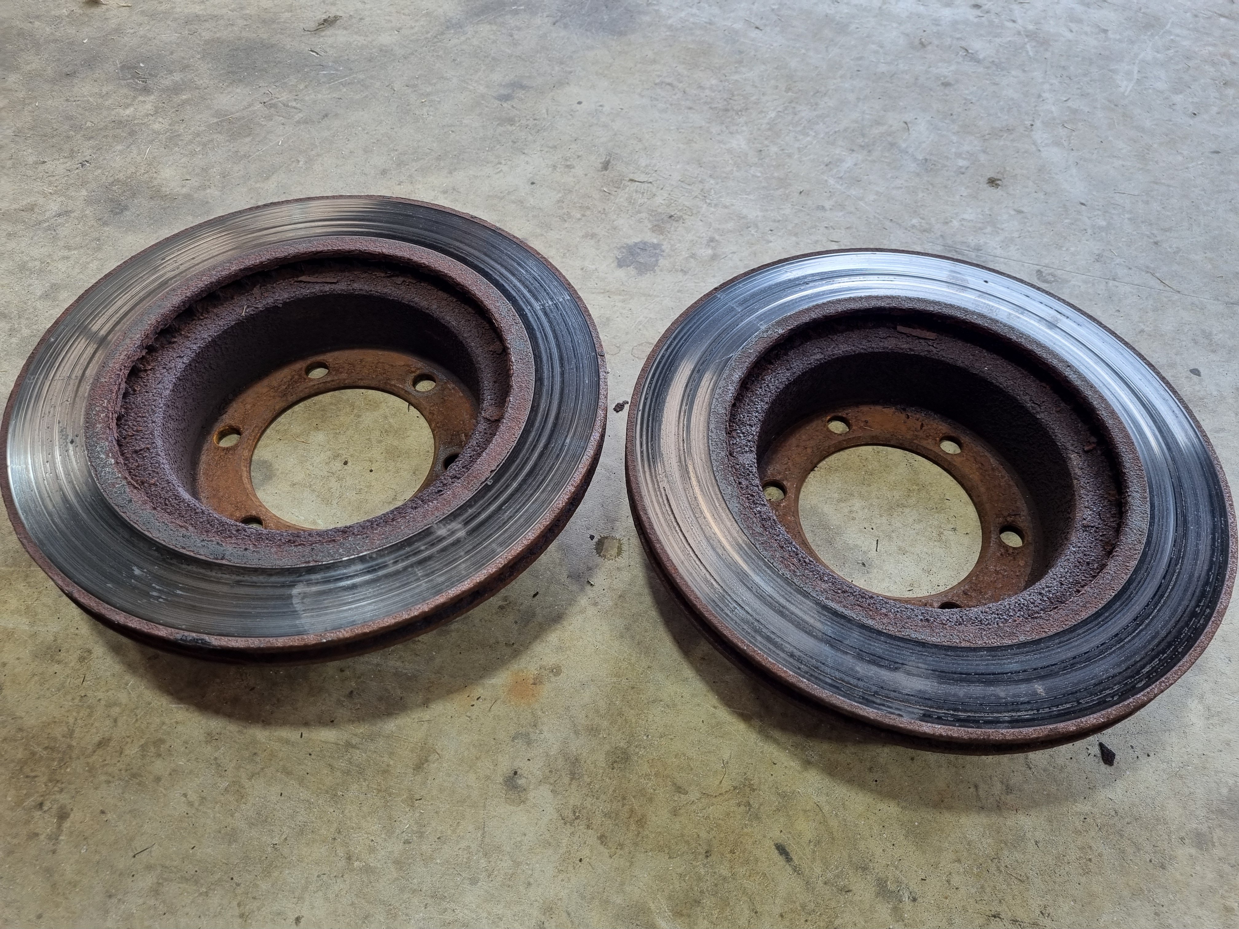
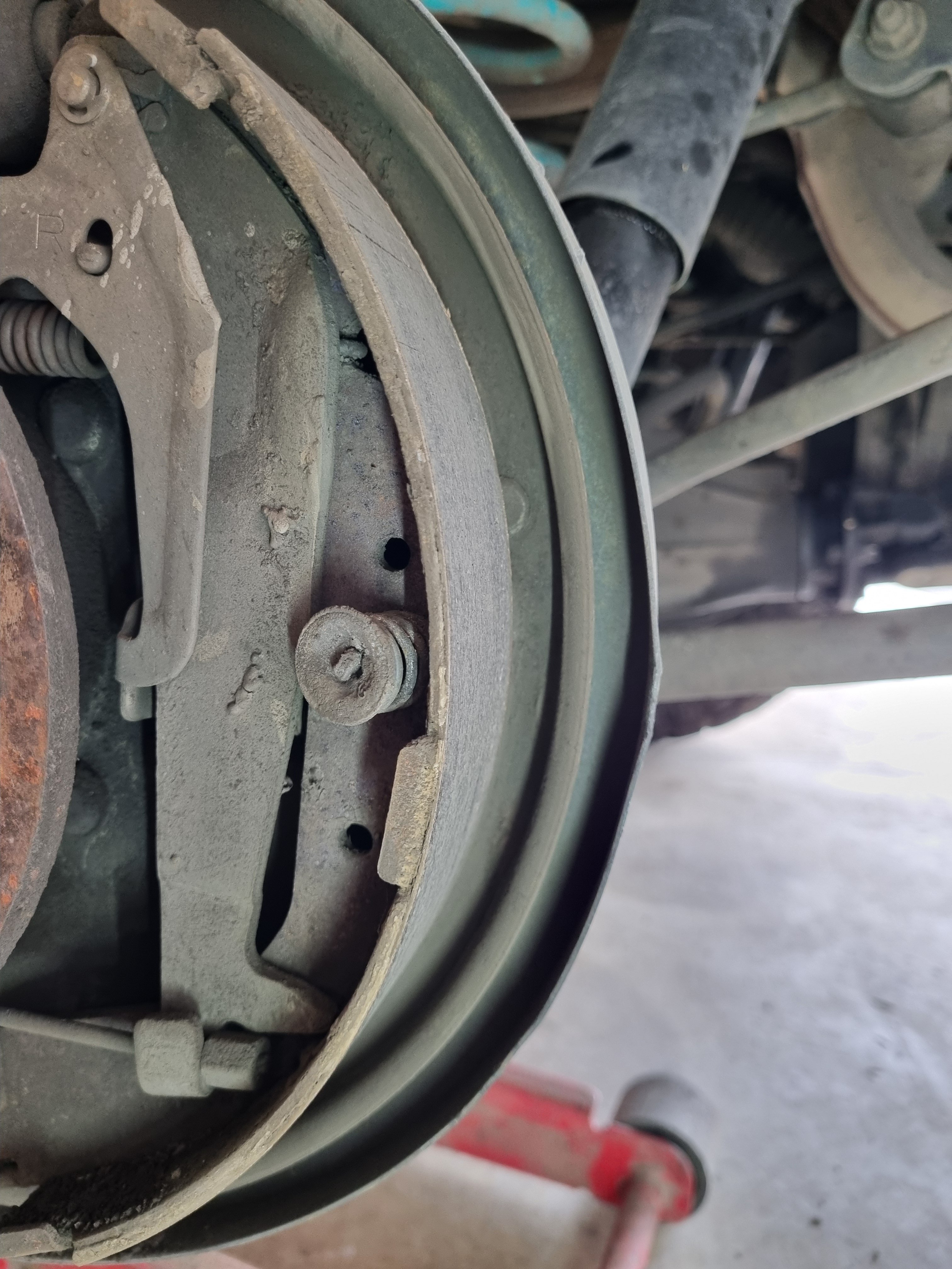
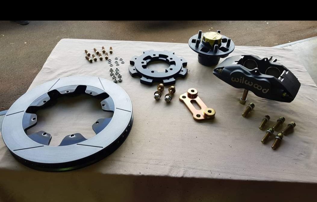
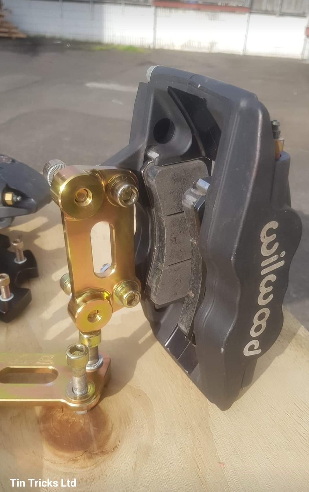
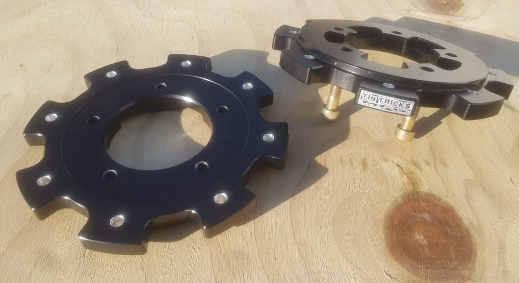
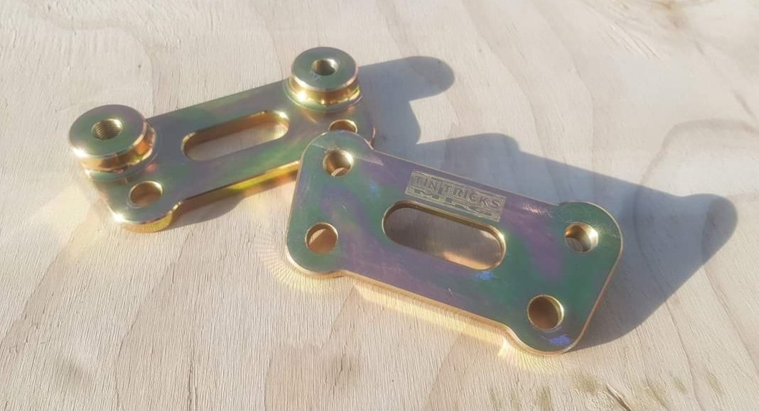
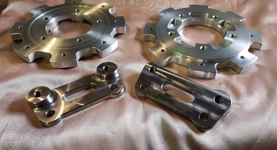
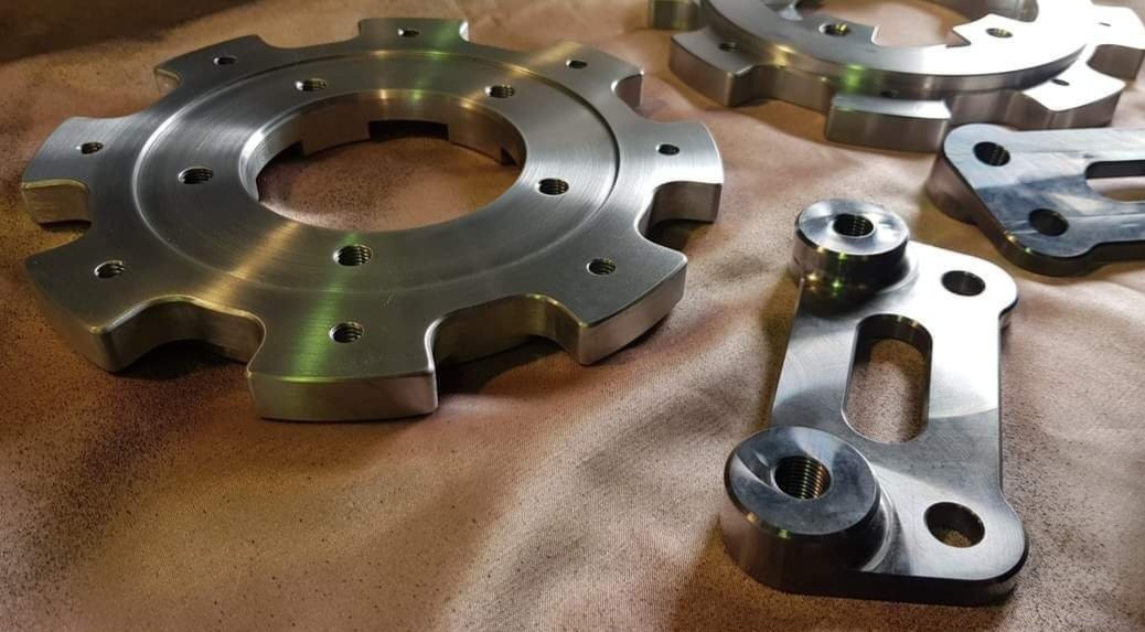
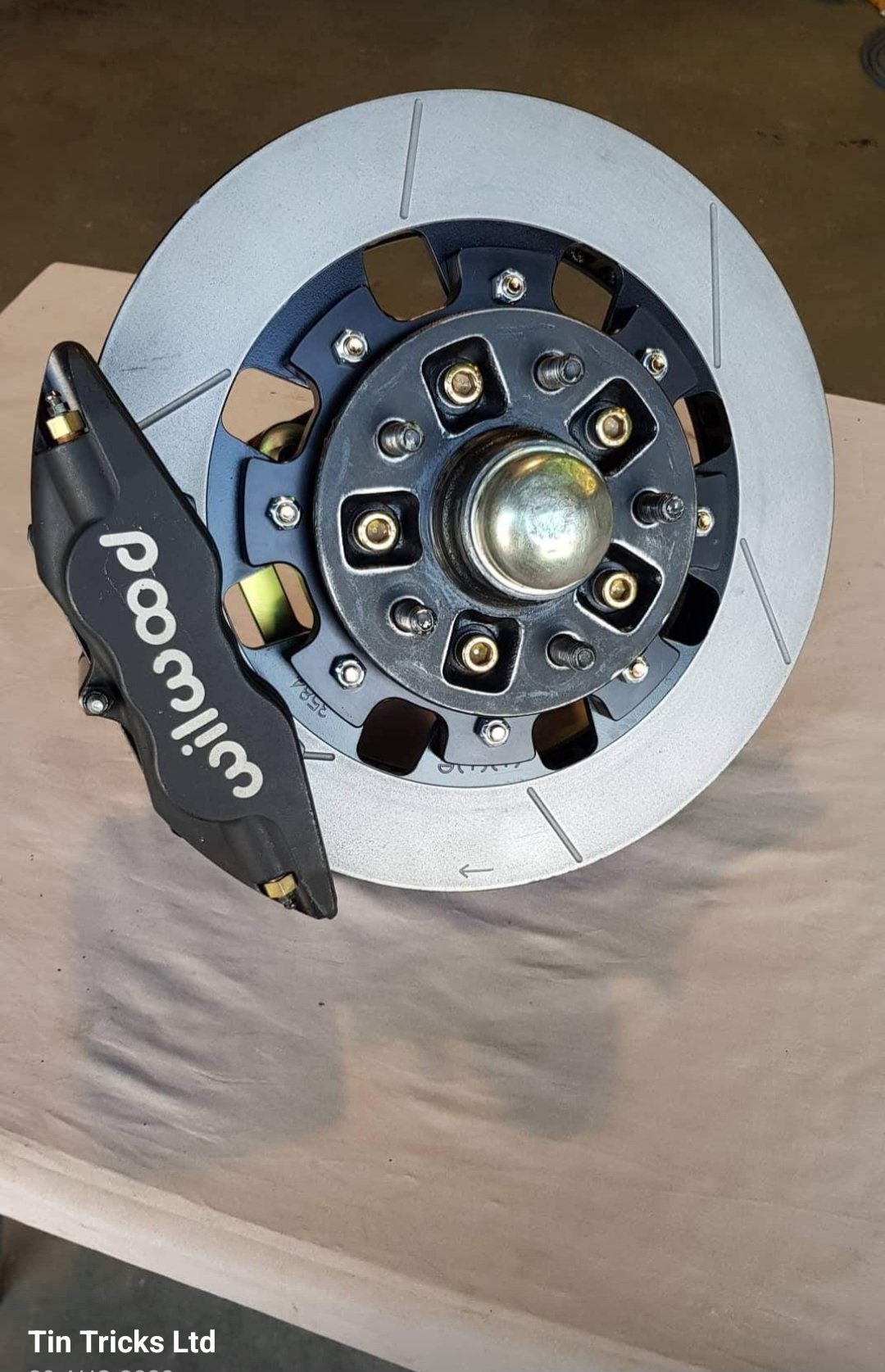
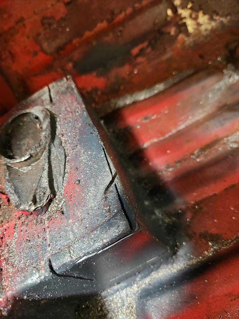
Nick recharged the AC system and now it works fucking ace. Couldn't feel my fingers by the time I got home so I'm calling that a win. Installation of new discs and drums. Front was easy, as you'd expect. Rear was a bit bit difficult to get the drum of due to the massive lip on the inside. However once I got the drum off I discovered the thinnest brake shoe I've ever seen. And of course the wheel cylinder was leaking so I'll get new bits next week and re- do the whole back brakes. Also I found the reason why I'm now the best 4wd driver in NZ. Auto disconnected sway bar for max flex bro. That's what the 4wd people say, you wouldn't understand.
4 points
-
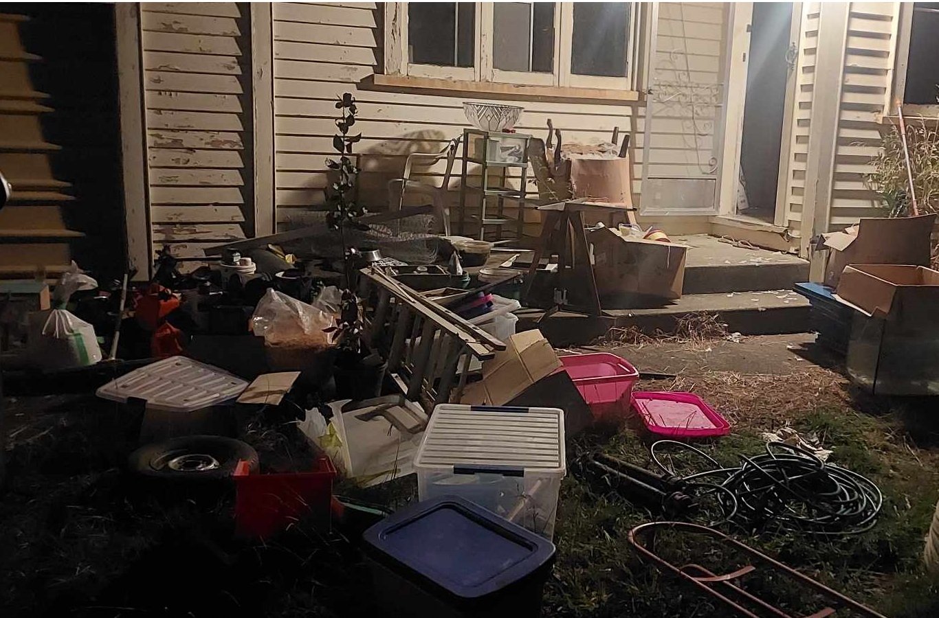
In January 2024 I suddenly needed somewhere to live in a hurry ... so I figured on building something small out of scraps of building materials I already had.. There's no power, water, sewer on the property, but 10 days ago we got most of the driveway in. I'm the kind of guy who thinks a fair bit before I act, so after some further thought most of the scrap timber/plumbing/etc. I had available got pushed to one side as they just weren't going to work. Queue more invoices for better timber (plus freight) I think this project will take until spring 2024 to be weathertight. Shipping delays and huge freight expenses will add to the timeframe and budget. For example I have $500 of under concrete insulation here at the port. The freight bill for that insulation alone was $1,200. The proposed dwelling will be single bedroom and about 60m2 I always start very well but never finish anything. Let's see what happens this time.3 points
-
Are you storing it in the ocean?3 points
-
'Oh yay' half of oldschool proclaim as we roll our eyes. I didn't need to know that. Looks back to all those fun days wiring brushing off old dry underseal3 points
-
Yeah I should have mentioned that in the thread. Might point it out next time. Yes- there is a standard rubber cover on the imp shifter base that will still fit. I think it was pictured in the pic of barrys shifter. I'll just need to add a shoulder under the base (as seen in the bits I cut out) Then along the underside of the tunnel Imps normally have a full length cover that bolts in place. I say normally because I do have one but its been sitting in the frunk of the spare imp shell waiting for me to clean it up, paint it and fit it to the blue imp. It's only been since 2019.. I've not yet damaged anything in the tunnel but this new setup is more exposed so I'll definitely be fitting the cover up!3 points
-
I will use those little slide on linkages that came with the throttles and will weld them to back of the pulleys. Then have some ability to set the angle when tightening it. I can also shorten or lengthen the cable. As one end can be unscrewed and moved. Then if it turns out i still need more fine adjustment. I will add a small tensioner wheel to the cable part way between, that can adjust to effectively tighten the cable.3 points
-
Great job, Isn't it amazing how much time and energy can go into a single component.. oh yeah I'll just whip up a shift mechanism that does exactly what I want and doesn't fall apart, or make shit ho backwards.. This is what the mx5 one ended up looking like, the Nissan box didn't come with a shifter, and needed to come forward anyway due to engine position.. (Note this was version 2)
3 points
-
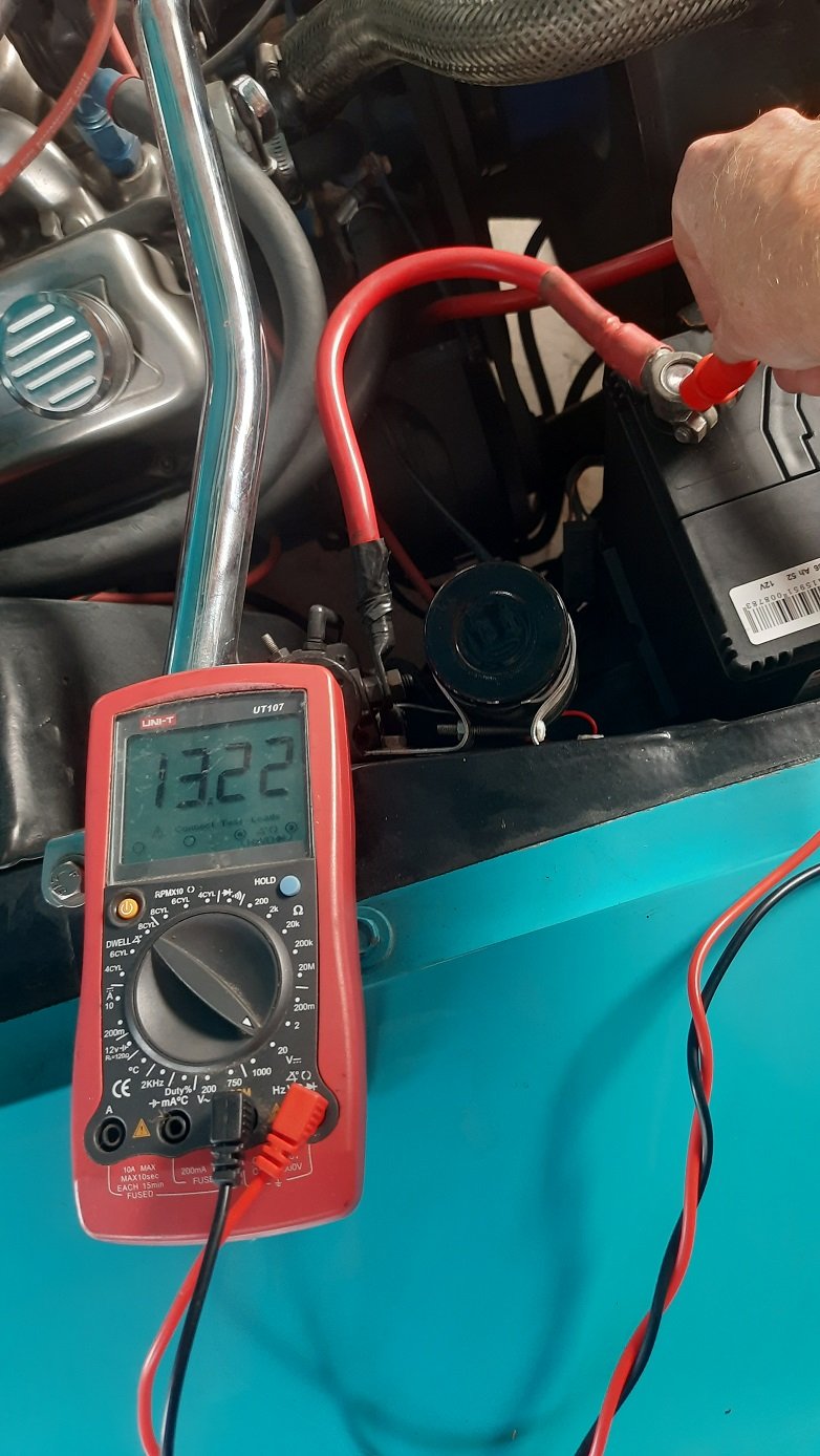
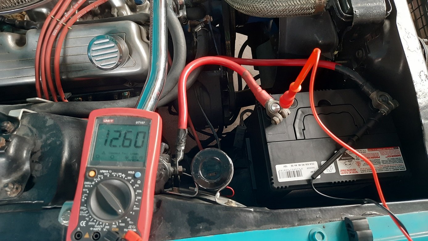
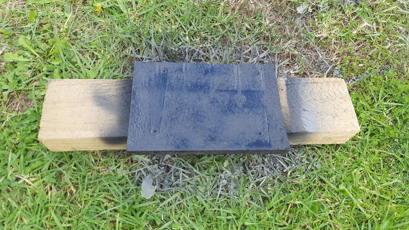
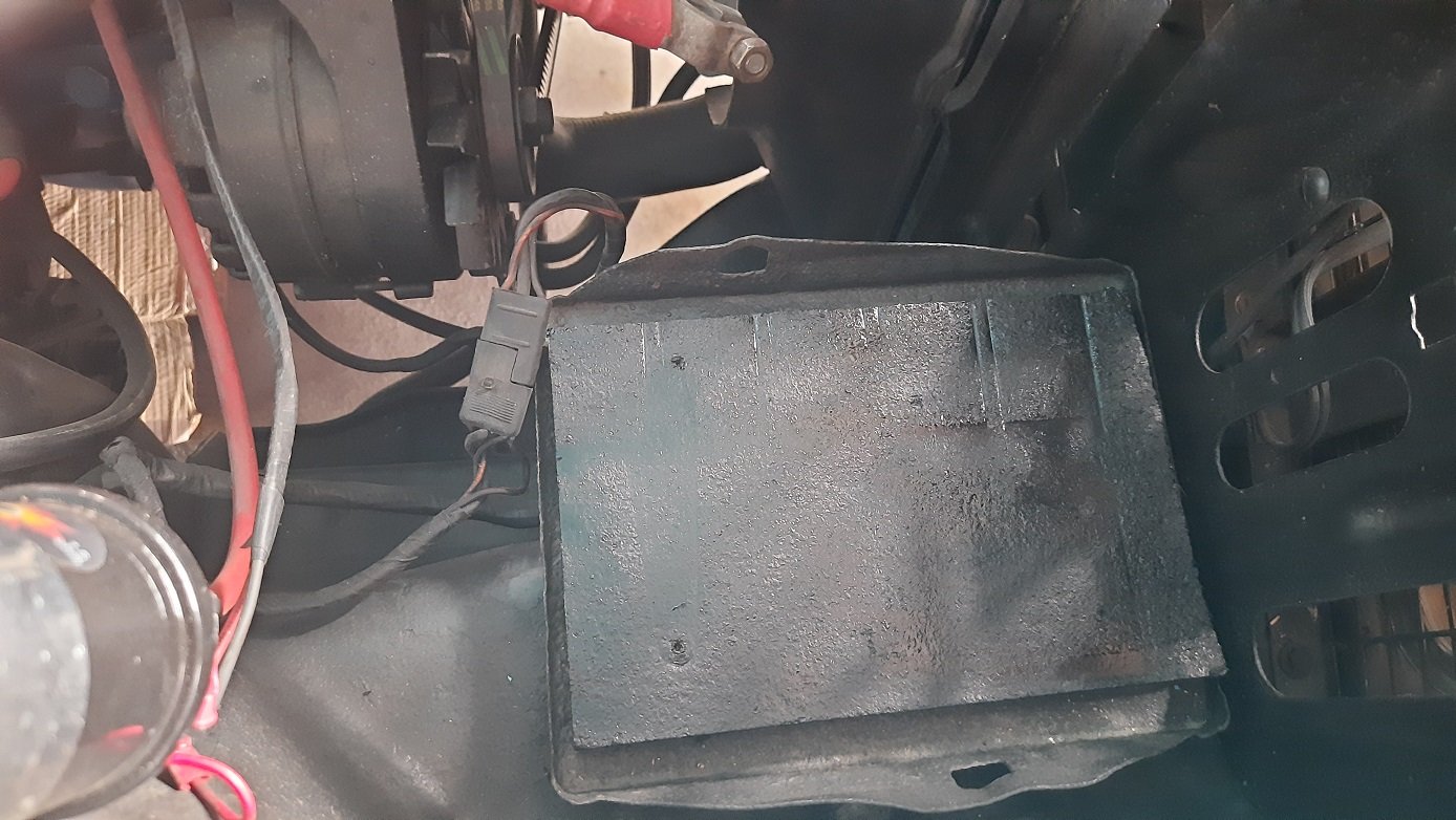
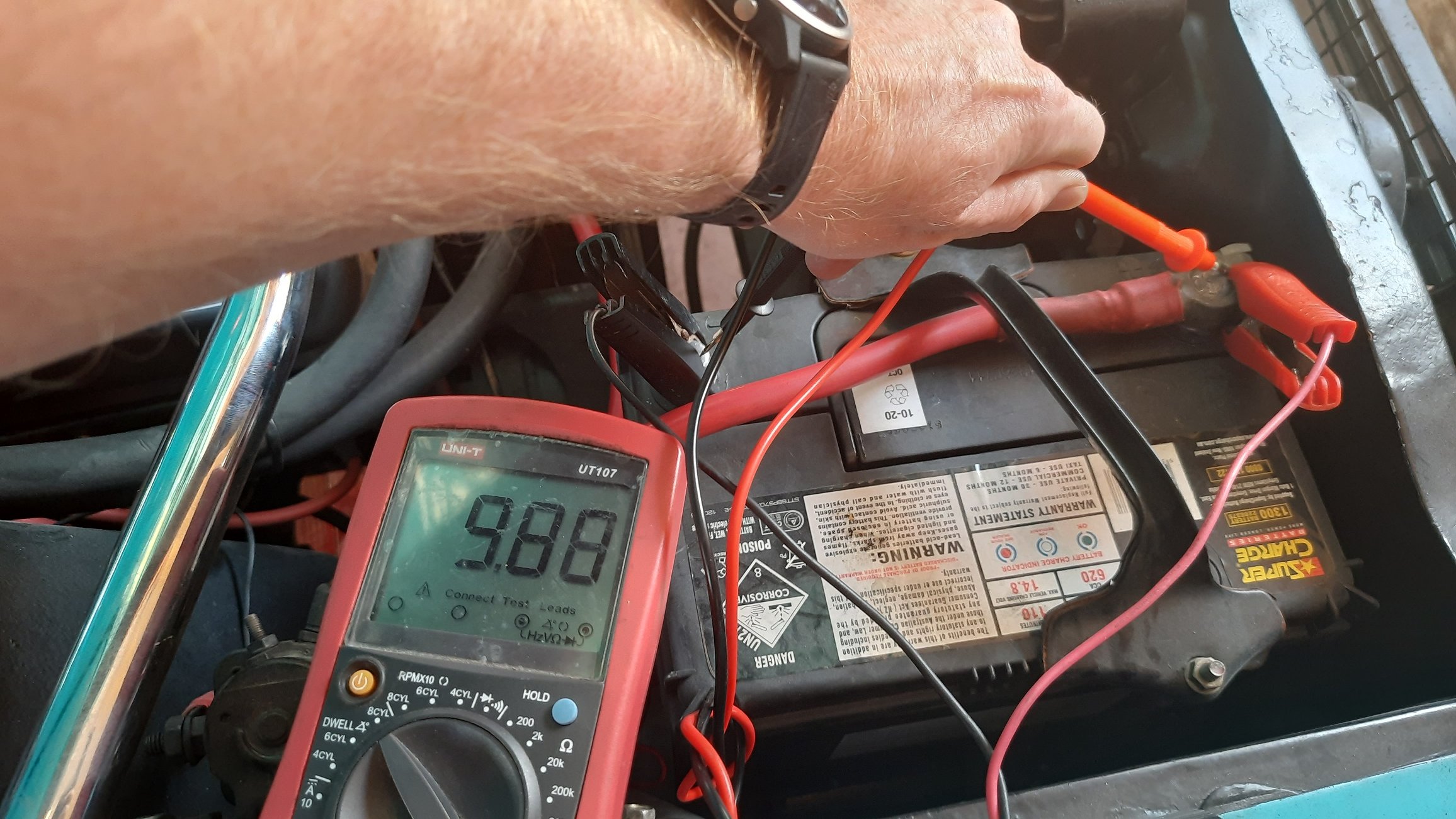
Went to Repco and got a new battery. Then went back to Repco to get the correct battery, (Repco branded) Century 68MF if anyone is interested. Threw it in and checked current draw. None. All good. Hooked it up and checked the voltage again, 12.6VDC, still good. thought it was sitting a little low and then remembered the battery spacer that was in it. High tech piece of particle board. Thought it could use a coat of paint. Looks like it was meant to be there. Last check was to fire it up and check the charge voltage. If it wasn't leakage current running it flat I needed to make sure the charge was within limits 13.2VDC at idle just after start, not too bad, needed a bit of a rev to see if it would come up to 14Vish. Got to 14V, then 15V then nearly 16V. Guess I know why the battery was toast. Guess I'll look at a new (internally regulated) alternator.
3 points
-
3 points
-
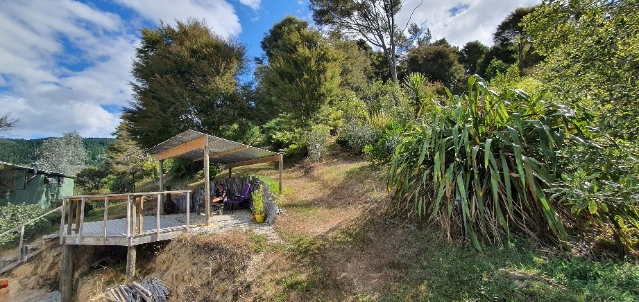
Hot-mix would cost all of the millions Corbie. I could probably do it cheaper in concrete TBH... but I'm happy enough with the crushed schist we've been laying over the last couple of weeks We were very fortunate to buy the property as land here is very, very hard to get. It's a little over 24ha with half a kilometre of sandy beach to the north and another half kilometre of semi-tidal lagoon edge to the south. It's an 'oldschool' title from the late 1800s so I own down to the high tide mark on both bodies of water. TBH I've never walked to the lagoon side of the property. It's a low lying wetland which will just need to stay like that for now. Today we collected timber, rebar and underfloor insulation from the port. Tomorrow I need to go to work to pay for some of it. Ha3 points
-
Sure is. They taste like a cross between turkey and duck2 points
-
Is that KFC in front of the JCB?2 points
-
The more I read these info snippets, the more I realise that I must be close to death already. Bogging, sanding, painting, grinding alloy , galvanic poisoning about 20 times. Yup way to look after myself. she’ll be right *sigh*2 points
-
Actually our K11 gearbox has a decent leak. Spent too much time hanging out with the naughty British kid and learnt bad traits I suspect.2 points
-
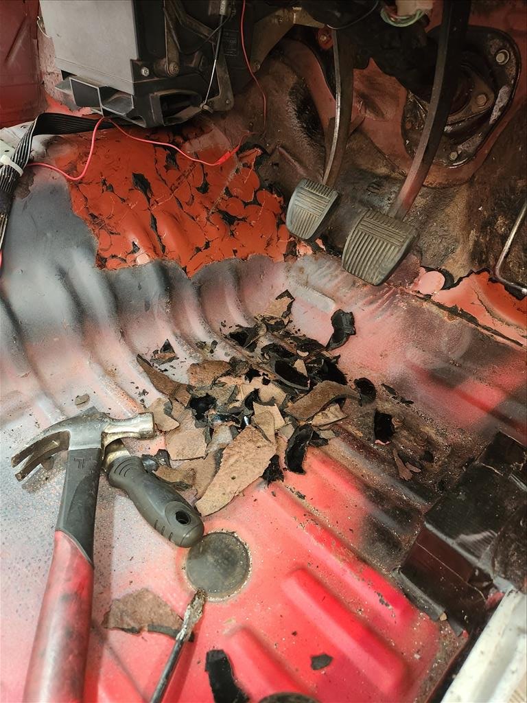
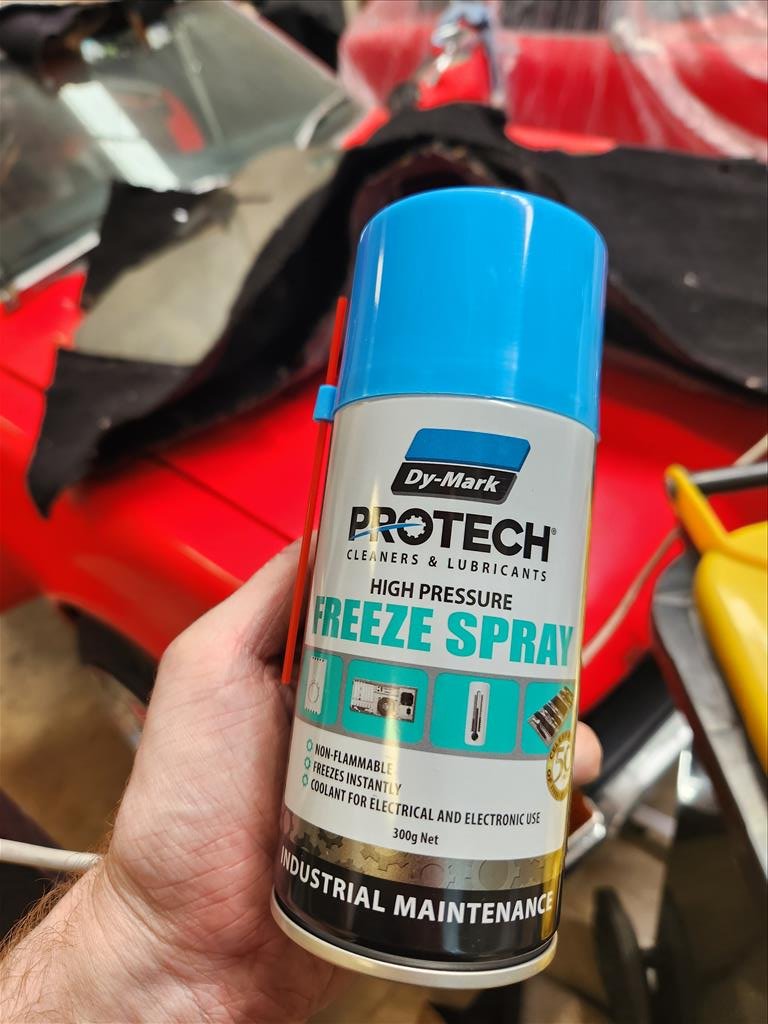
I picked up a saw during the week and had a go at cutting, didn't get very far before the blade decided to become smooth and basically just polish things. Smoke fell out of it too. So today I learnt there are different blades for cutting different thickness of metal. I've now spent my life savings again to buy a bunch of blades for chonker steel. If that doesn't work then I give up and will just get new carpet and cut around these stupid boxes. I did conduct a somewhat successful experiment with sound deadening though. I was reading about how to remove sound deadening without dry ice and this freeze spray stuff came up a few times so I gave it a shot. It didn't work too bad but it would be a ludicriously expensive way to actually remove large portions of sound deadening. Just getting the chips of this little bit used up the whole can. I haven't really worked out where the cuts for these boxes will be done but hopefully when I start to cut things it will make more sense depending on what access becomes available.
2 points
-
2 points
-
2 points
-
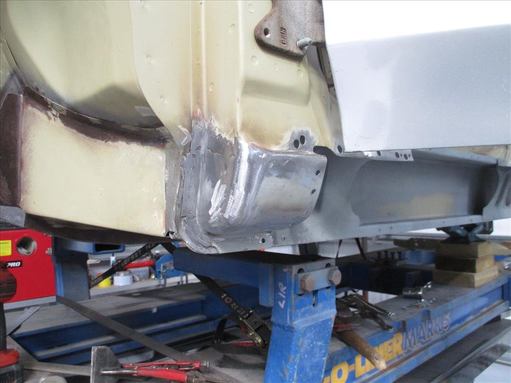
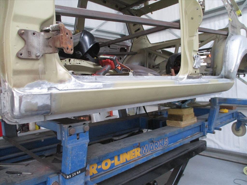
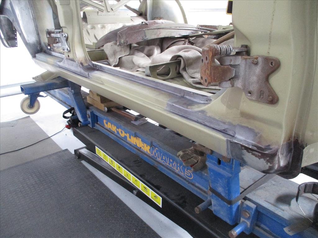
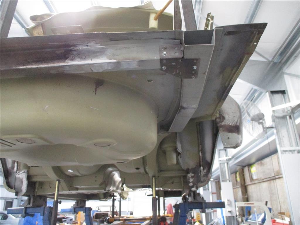
Another email from panel Barry come through recently. He's been spending time cleaning up the sills and preparing for the final weld in as well as getting all the welds in the rear floor/boot area ready to support the rear end going back together.
2 points
-
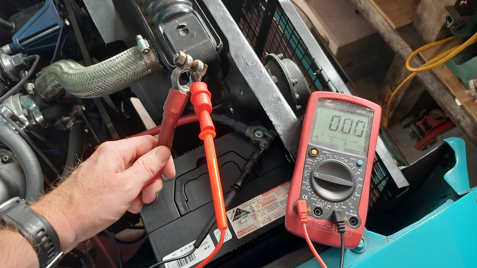
I think I might know what the starting problem is... Pretty sure that should be something over 12VDC. Charged it for another 24hrs with it disconnected from the car and still 9.8V. This has dropped at least one cell, probably shorted since it had none volts before I charged it. I haven't checked the alternator voltage but I'll get a new battery and check it then. The car could still have a short draining the battery but easy enough to check if there is current draw when I fit the new one.
2 points
-
Ha. So pretty much the day after I had cleaned up that old alternator up and got it running on the engine the second hand replacement for my original unit turned up in the post. It came with a 3 month warranty so I'd better check it works before stripping the engine of its ecu etc. Started to fit it and oh.. Poos. It wont fit. So I took it apart, along with the original.. Discovered its just the front housing that's different and I can swap them across.. So while its apart it would be rude not to clean all the parts up and polish it all (tempting fate just a bit...) Fitted to the engine and started it up. Yay - it works and it looks great, which is really quite important given its right there, in the middle on display. I'll keep the other one in storage just in case I need it one day. Now I could strip the engine back down, removing all the cooling, wiring and fuel lines that I had installed just for bench testing. Then I removed the transmission and put the engine back onto the engine stand 2000, stashing it away because its gearbox tinkering time. This Leone transmission has a few little issues that need sorting out in order for it to run in reverse rotation and not potentially turn itself into an expensive insinkerator or coffee grinder. I could probably get away without doing these modifications because the box is overbuilt for the application but I wanted peace of mind. Remember I had acquired the two gearboxes, 1600 and 1800 items, before getting the engine. Ages ago, in fact 4 years ago I think!!! I had wanted to know if it was feasible to run these boxes in reverse. This pic I posted up way back then gives a good idea on what's going on inside... I had already worked out some of the issues back then and knew what I was up for. With more study I found a couple of other areas that need addressing. Here's another bit of wonderful scribbling I did this evening.. The pink arrows show the new axial forces that are being imparted onto the main (driver) shaft and pinion (driven) shaft. The circles are areas that I think needed attention to make sure it doesn't throw it toys from the cot. 1 : the blue circle. Under high torque loads this area could possibly create the sound of nashing teeth but with much messier consequences. The top left one being the third gear driver wants to move to the right and clip the teeth on the bottom right second gear. In normal rotation they would move apart. There's 1mm of clearance there which is probably enough tbh. But I wanted a bit more and had already worked out how I could get it with no other issues and just a bit of tool making. Which is fun. 2 : The yellow circle. This ring was no going to take thrust loading. It is a strong ring and has a deep groove but I wanted to make sure there was no way it could ever shift. 3 : the green circle. In this area there is a thrust bearing that also acts as a neat little oil pump and squeezes oil through the gear hubs/bushes. Under the new loading the thrust aspect is removed but I still wanted to it pump oil and it was going to be the wrong shape to do so in reverse rotation. So I set to work and checked off each job. I made a bolt holder for ease of reassembly - several different sizes and lengths. Once apart I started with the gear side clearance. First off I needed to split the mainshaft assembly down. 4 years ago I had out of interest tried using a puller on the spare 1600 box, which shares the same layout and design but with smaller parts in many cases. The puller didn't work. But this time round I have the rather handy workshop press I made. I just needed some extra tooling to do this job. Starting with some press plates... Allowing me to carefully press the shaft out... Because I'm not posh (or rich) enough to own a surface grinder I needed to make one. Yes its a bit basic but it will work. I made this... Which allowed me to do this.... I ended up with this gear having the 0.5mm more clearance I wanted. Super happy with the result. Now onto number 3 - the little oil pumpy thingee. I went to my friendly engineering workshop in town and got a big lump of 4140 steel. I drilled it out... Machined out a ring which had to be an exact width. Just in case it needed finishing after the hardening process I made an abor to take it.. I carefully machined it to the right profile, cut the sides down and filed the shapes in, just like the original but in reverse. Happy it was going to work I heat treated it. I have not done any heat treating for over 25 years since I spent a fair bit of time in the blacksmith department while doing my apprenticeship. But it wasn't a super loaded critical component and just had to have a durable hard surface. I didn't take any photos. Hannah was there helping as I carefully heated it up with the oxycet to the austenitic stage and agitated it in some lovely rice bran oil (because I can be posh sometimes) then slapped it in the oven to temper it... Following morning I polished it. It came up sweet and the old file test showed it to be as hard as the oem item. You can see the reversed design here... Here's a little vid I took showing it in action... While stripping the mainshaft down I was also pleasantly surprised to discover that this 1800 box has needle bearings in all of the gear hubs unlike the 1600 box which uses bushes on the mainshaft. So oil starvation would not have been as much of an issue but I'm still really happy I did this modification. Last issue to sort was number two - that ring on the bearing. It would hold fine I'm sure but if could make it bulletproof then why not - it's just a bit of extra machining. I started with another lump of high tensile steel and machined out a ring to suit... This fits over the other ring and then the main thrust plate that sits over the bearing was machined out to suit my reinforcement ring. Its all held in place by the end housing which I have yet to fit. All the potential issues covered I set to cleaning out the casing and then started reassembly. In doing so I discovered that the original axle seals are sided on these boxes. They have those helical lines on the lip surfaces which aid in pulling/pumping oil back into the oil side of the lip ( the lip does not actually touch the steel when the axle is moving and in fact runs on a tiny bed of oil) which I had not realised before I'd bought plain lip seals from an engineering supplies. This pumping capacity is shown to be twice as high in helixed seals. Subaru fit left and right handed items. But I'm running mine in reverse. Luckily the originals were in excellent condition anyway so I machined up a stepped tool, popped them out and swapped them to the other side. The diff axle seal surfaces came up good after a clean. Cute little diff.. I'm now about ready to put some 3 bond gloop on the case half and drop the other side in place. Its looking all very nice, clean and shiny in there...2 points
-
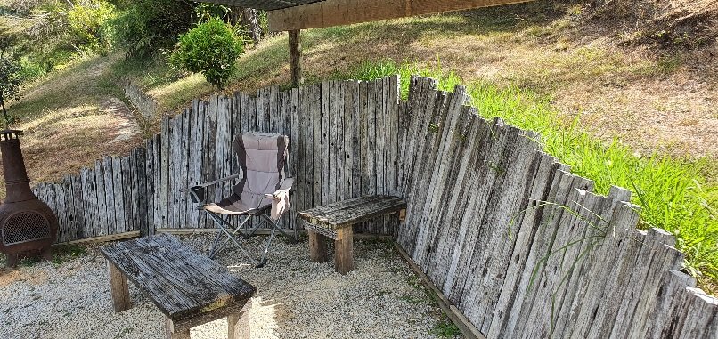
Couldn't stop there. Need a place for coffee mugs.. It's a nice little spot now. We are owed a whole load of macrocarpa from a customer so will soon build bench seating along the back.
2 points
-
I'd imagine you would do a full under tray for hyper mileing I want to do one fory nissan (and catching drips)1 point
-
Yeah good place to start, I've got a drum mc on my car and it had an issue with the brakes staying on slightly, popped the residual pressure valves out and smoooooth sailing after that1 point
-
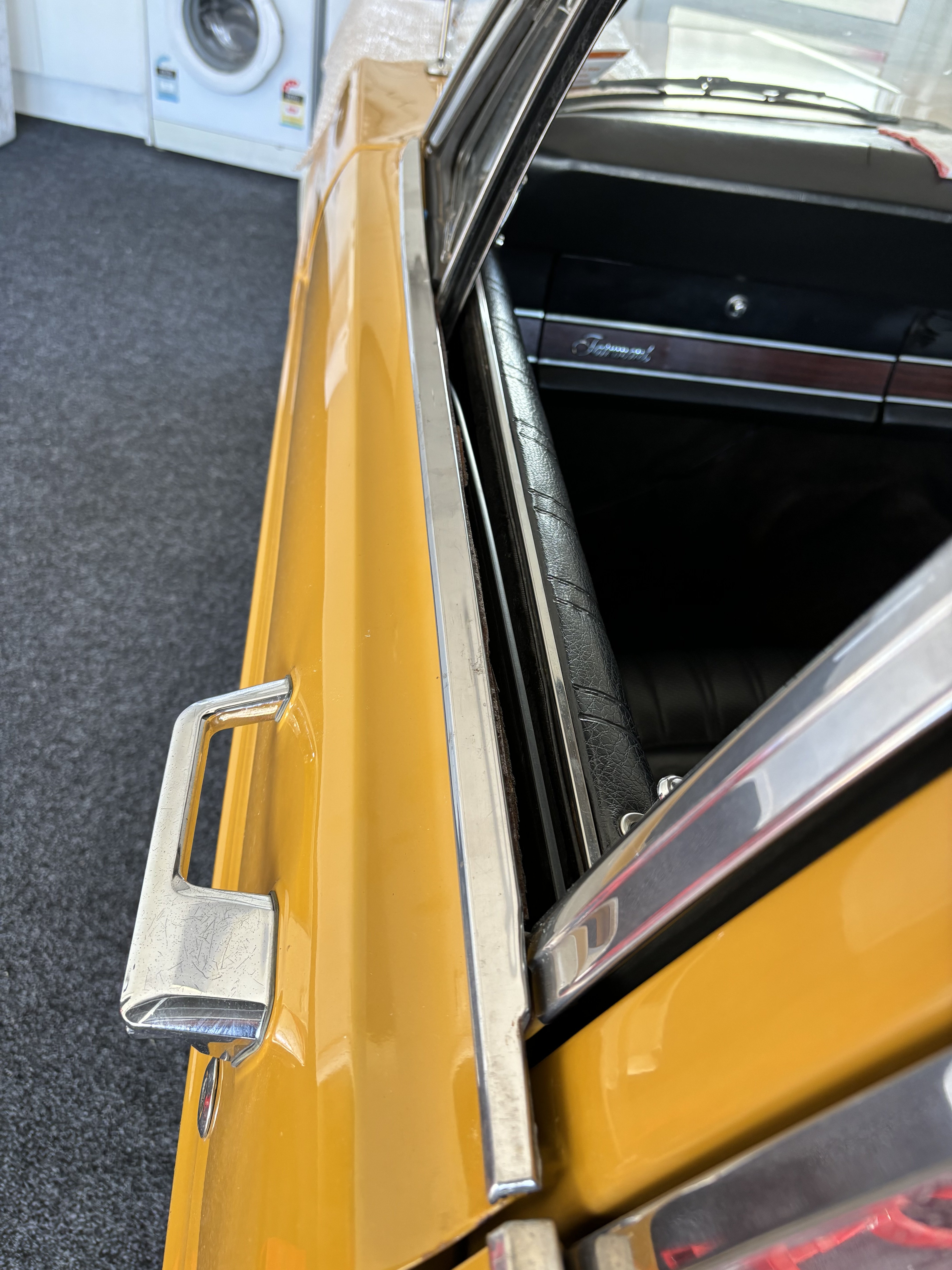
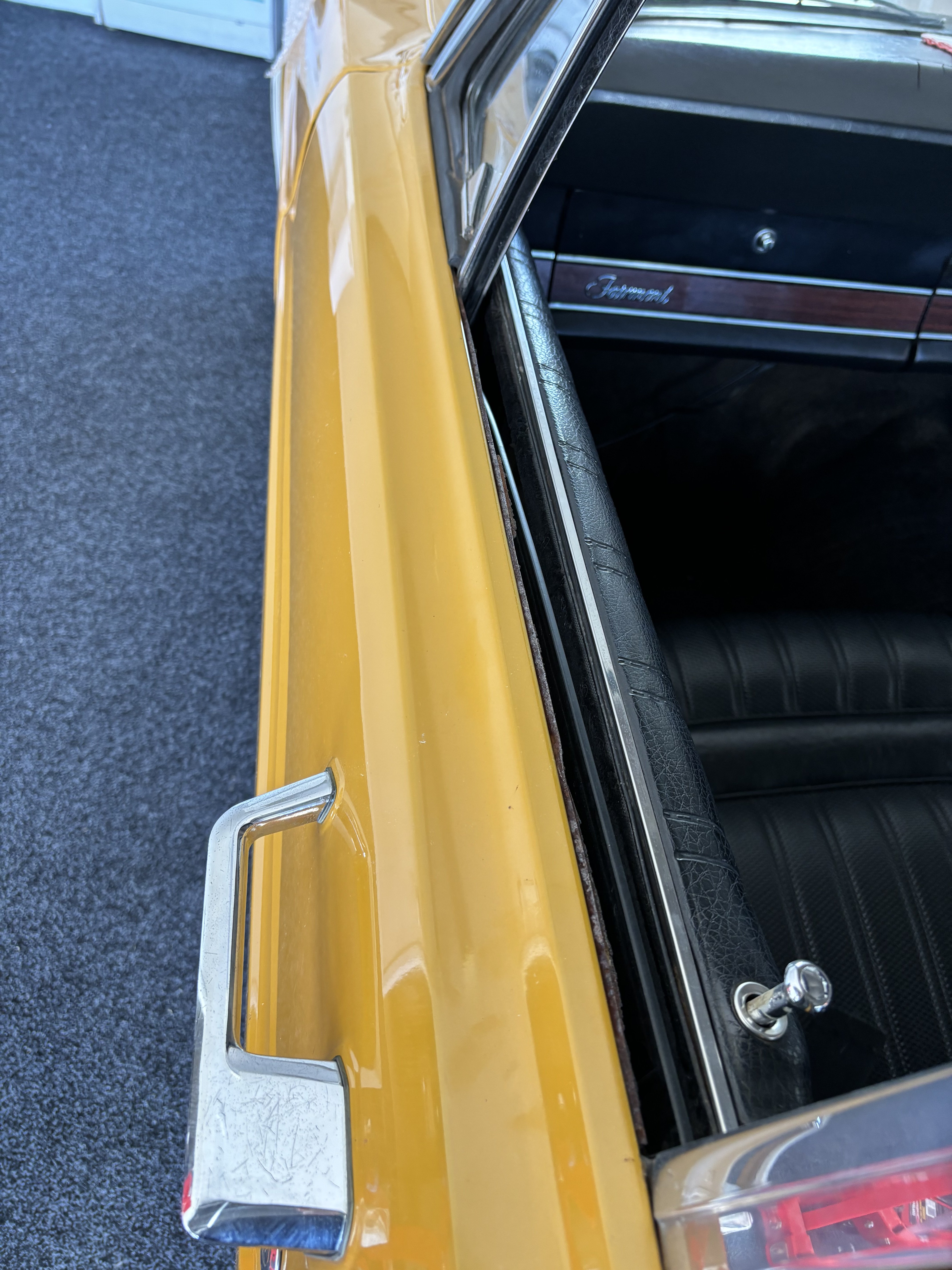
I finally got a set of top door stainless trim for all 4 doors. I’m way too drop nuts to drill holes to mount them but.
1 point
-
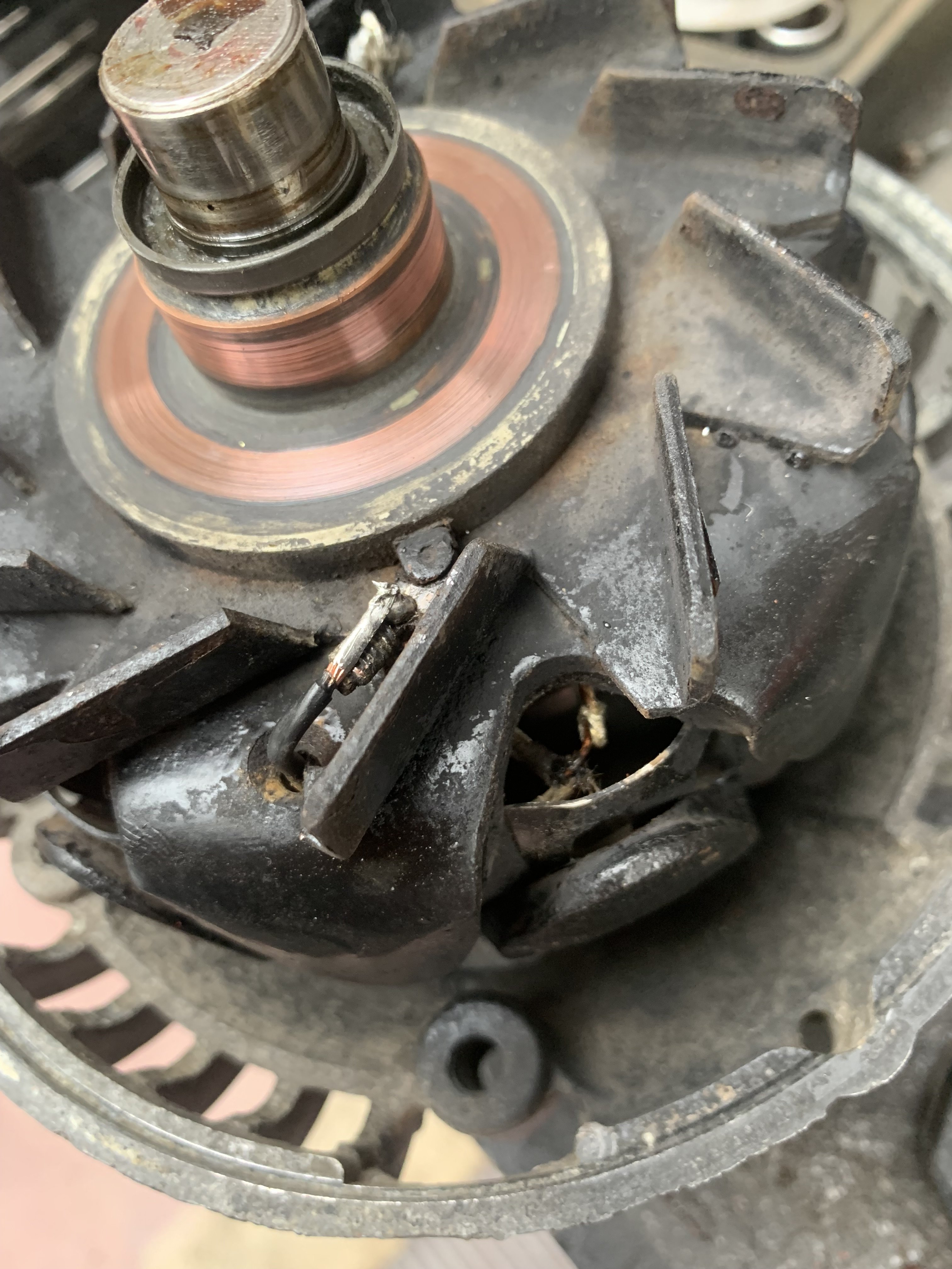
I had Lets Get Graphic re-make my side billboards in proper vinyl..much better! Accordingly the duraseal peeled off the adhesive and then they had to thinners off stubborn glue..oops. Took it for its biggest run out to rangiora MCM show.. went great until the needles wiggled and it stumbled then the Amp gauge read drain. Parked it up and left it until the trip home couple days later, it did it again but didnt hinder the journey. Few hundred metres from home it backfired and the needle came back to life and it was charging again! By the time id washed it and drove back in shed it wasnt charging again. Tore it open and spotted a broken field wire so i soldered it back on and not change. Weird. Fucked aroubd with tests and bypassing things, external reg tested ok. Left it with a customer whos a sparky, could tell he wasnt into it but said hed take a look but his test bench wasnt working. Few weeks passed so i went and grabbed it back. He did say the wire sheath looked like it was degrading and it might be earthing. Put my pick under the other field wire to tweak it into open space and there was no pull resistance..broken too. Was a bit awkward but soldered a new wire in between the broken ends and threw it back on, Amp gauge working! Then it stopped. Decided it was the centrifugal forces throwing it out and the wee bare wire patch was touching so dripped epoxy glue in/on to make a protective sheath and its been great since. Will get another Alt cause its pretty fragile and old.
1 point
-
I keep seeing Max peed in his grods. Is that a euphemism for undies?1 point
-
So I’ve been in a battle with these back wheels, 14x9.5 -33 doesn’t fit well in stock rear guards as I wanted and I still had no luck trying to find factory 9j A type mk3. I got these polished up and painted them in a krylon glitter blast paint which was a pain in the ass to spray. after much deliberation I decided to stick with the ones I have, I then decided I should try and narrow the subframe to fit, I friend mentioned another old Toyotas axles weee slightly shorter and could work, so i set about jigging up the subframe and moving the trailing arm mounts in 12mm or so. Before After Both images on an unrolled stock guard which worked great. while I was there I decided I might aswell raise the diff and make a bit of an exhaust tunnel. I’m terrible at taking photos as I do stuff so here’s the finished result, only needed to fold the lip up of the guard and it fits great. needing to drop a tire size in the front to 165/60 and get it lower all round but it’s starting to get there. I also got a custom made Jeff emporium steering wheel which turned out great and he also refurbished the trd gearknob that came on the car too. still need to clean to OEM floor mats and get them back in the car to tidy up the interior
1 point
-
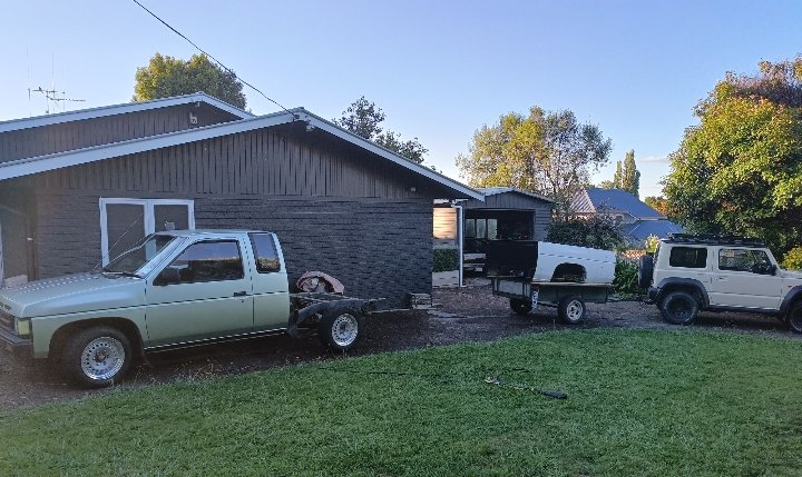
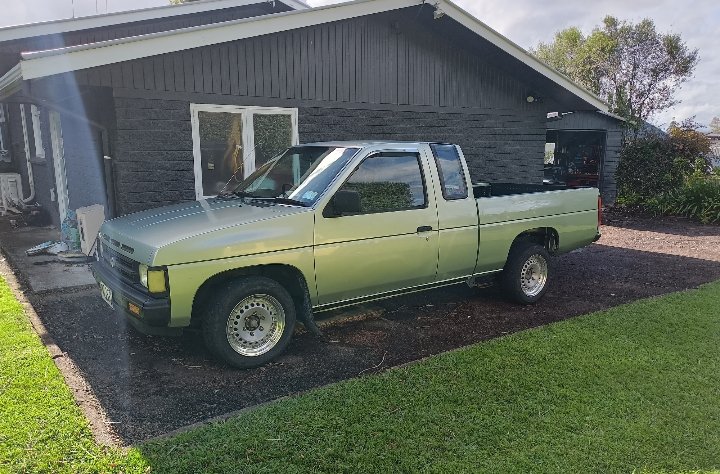
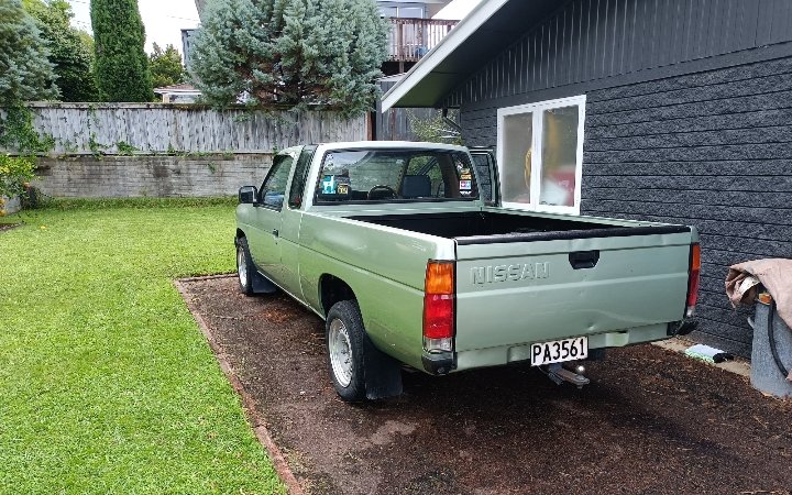
Not sure really. It looks like a finished project at some point. Ill be able to take loads of parts off it for mine. Just where it was on the coastline in Welly it was always going to get smashed by salt.
1 point
-
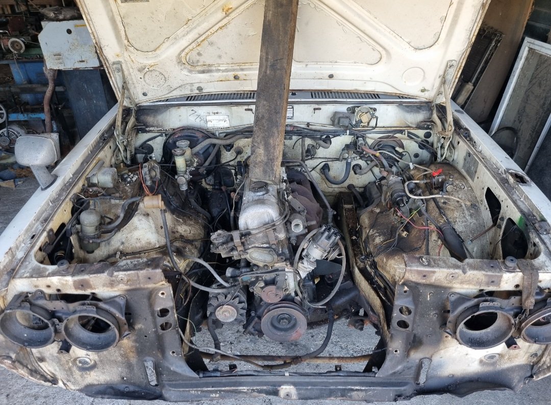
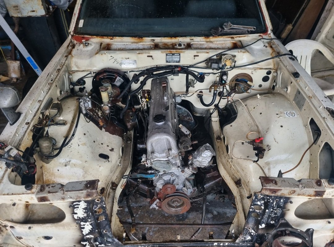
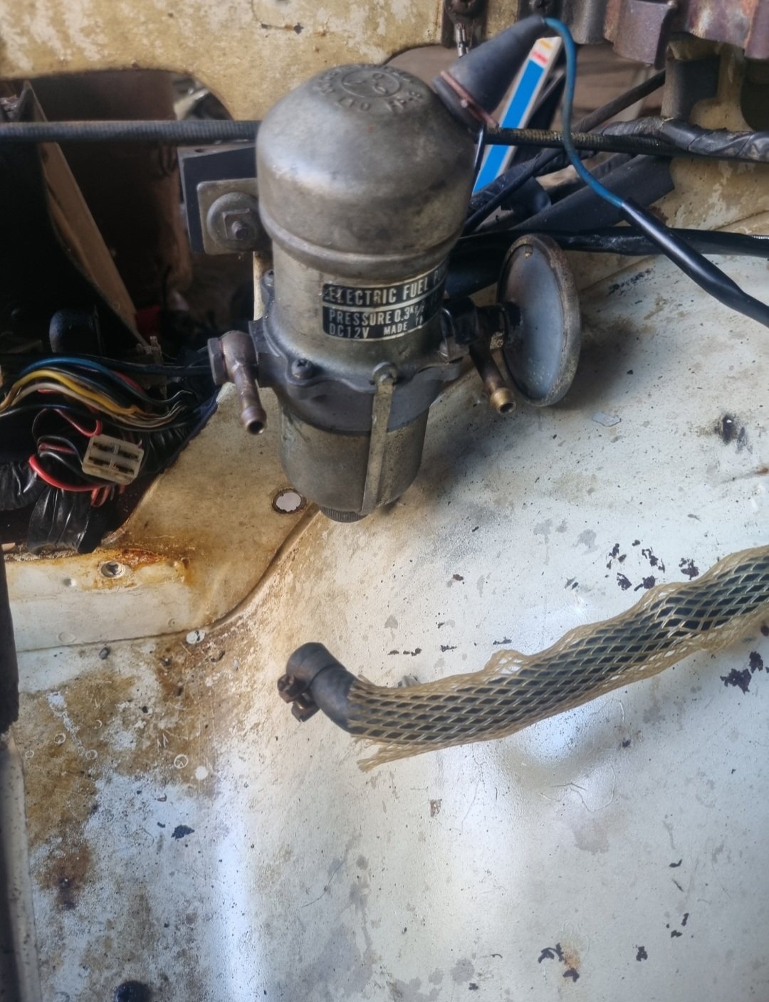
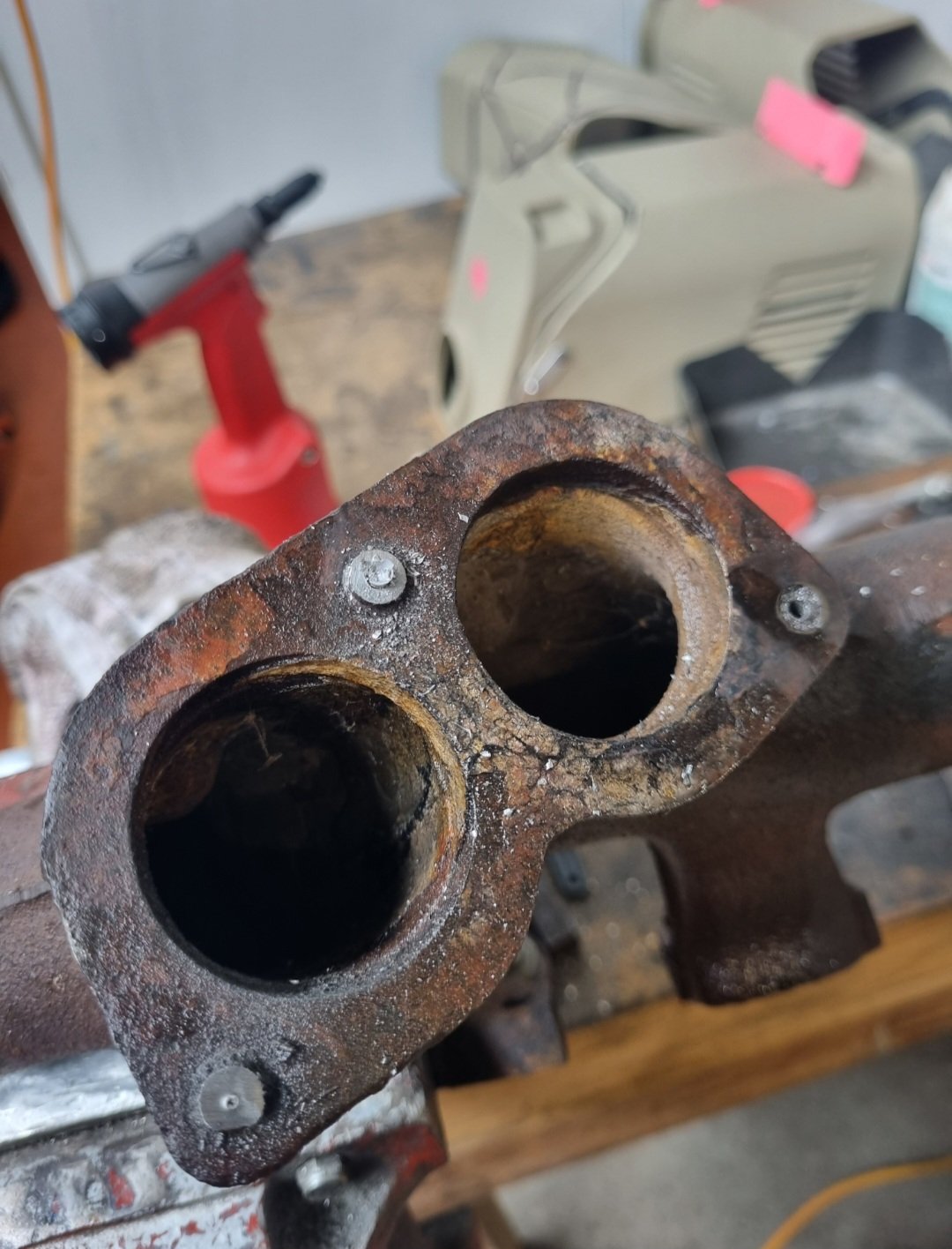
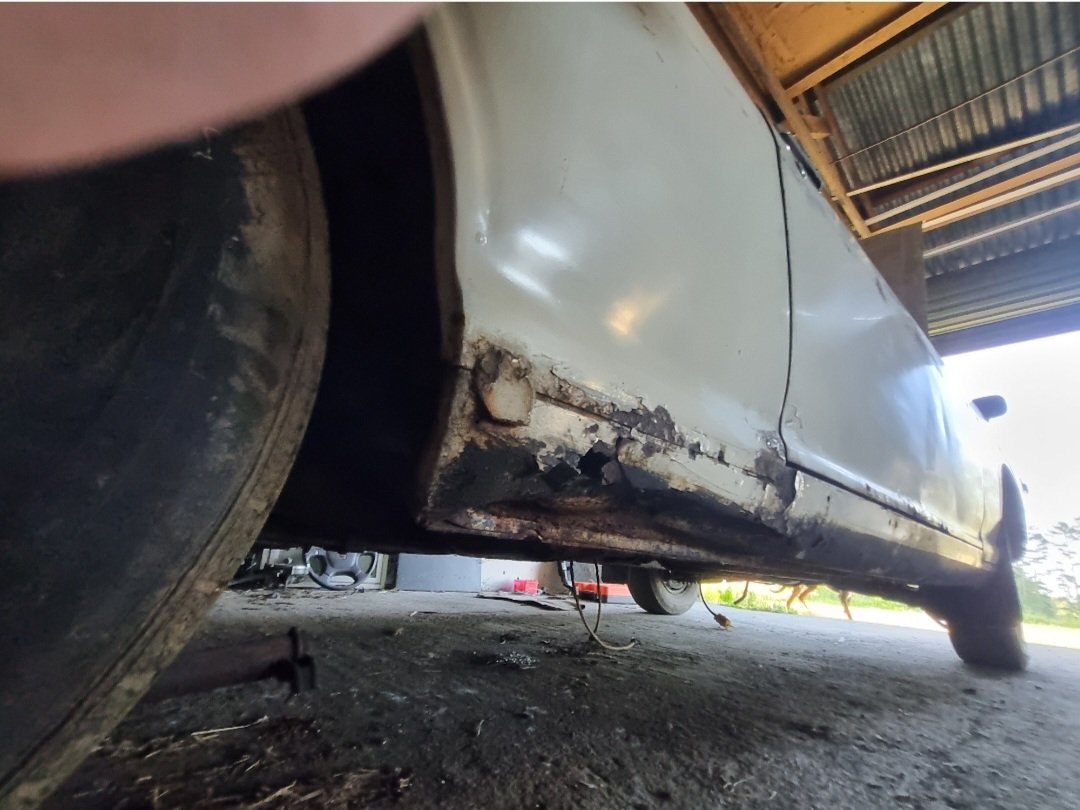
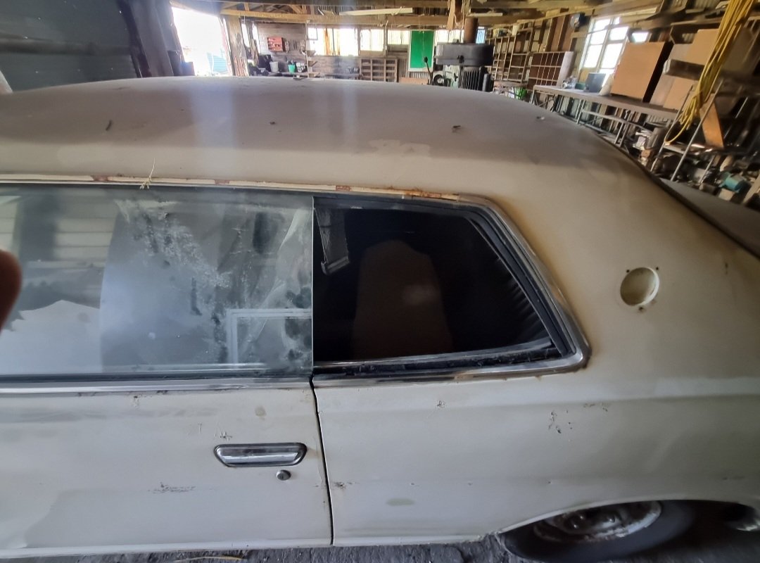
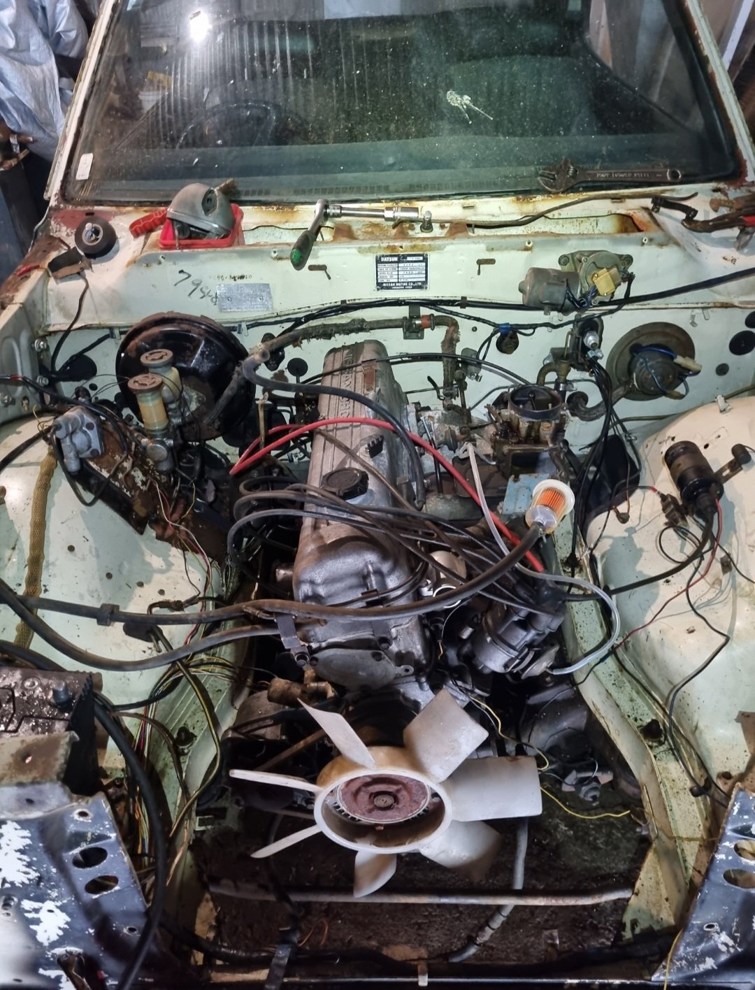
Been a few weeks now since I've had this thing. Started by deskunging engine bay with degreaser and waterblaster. Lucky my shed at home is so shit, as I had to waterblast it inside as the brakes are still seized. Before and after Removed a whole lot of junk out of the engine bay. Was originally a CNG car so all that shit went in the bin. Also had a/C so I pulled all that out too as I have no pump and the rest of it looked pretty unserviceable. Keeping it simple for now but would love the opportunity a/C eventually. Then set to deciphering the basket case wiring. It's like 15 year old me had been there and thought I could improve on it. Bit of work with the test light and had it all figured out. A lot of fuckery was going on but I got to the bottom of it. Had an electric pump owing to the CNG, I didn't hold much hope but shorting it sprung it into life. Next up removing many broken studs and retapping holes. All gravy. The big news today however is that after finding all the various parts that were strewn all through it (thankfully only a few bits are missing), and assembling back onto the engine with a new manifold gasket, thanks to @fletch new front pulley (had big chunk missing) and new thermostat housing. Old bitch fired up, after my comedy of errors forgetting to install rotor...woops! Thing runs mint, oil pressure around 60psi so I'm happy. I'm surprised it actually ran on the decayed plugs I cleaned up and shitty leads, but firing on 6 and sounding like she's ready for the demo derby! I'm stoked Have also cleaned and vacuumed out the rat shit from inside and pulled the old house carpet out and, whilst not mint inside is really not too bad. Door trims are a bit fucked and the seats have a few tears, as well as missing rear seat base, but otherwise good. Have assessed the rust situation and for an old Datsun it's really pretty good. The floor is mint. I mean mint. One pinhole. Engine bay also only a few pinholes, front cross member is toast though, so will remake once I get a rad support panel. A little bit on inner sills above floor, and both outer sills need replacement. One lower door needs a little bit of work, other is mint, as are the front guards, barring some dents and shit. Lower rear quarters and rear valance are toast, and boot floor either side of wheel well needs replacing. Not looking forward to finding a passenger's side rear window however... Next mish is to tidy up the bay wiring proper and perhaps get the brakes working so I can do some skids. That's why you own a Datsun. Will then work from front towards the back on the body work. This is not taking precedent over the camper, I have simply had more time to tutu with it in the school hols. Have spent a grand total of about $45 on parts so far to get it running, sold off some shit too which has offset the price of a set of widened steelies @ThePog kindly located for me in the mainland. Chur.
1 point
-
Bench testing continued. The sump was now holding oil. Phew. I fitted the old smiths mechanical oil pressure gauge that was originally fitted in the imp race car. I mounted the gauge to the temporary coil stand. With the engine cranking over it was seeing about 20 psi. The oil level would drop in the sight glass and after a minute or two it would be back to the old level. I was happy with this. Next on the list was to check the idle control valve was working. Its a 2 wire Bosch style pwm type unit. Very common, simple, reliable and hence used often in megasquirt installs. Its basically a rotary valve that is opened against spring pressure by a solenoid windings when current passes through them. The ecu earths its ground wire in a series of pulses, the quicker the pulses the more it stays 'open'. Simple as I thought.. but.. this is where I discovered that I had bought one of the units that is actually 'closed' at about 30% duty cycle. A failsafe on cars that use these for closed loop idle control (aircon/powersteering/epic sound systems etc etc) If the valve fails then spring pressure actually takes it to a slightly open state so the car cant stall. But I'm only using the valve for open loop at start up. So when its closed I want it to be closed. Luckily I was able to pick out/burn/pick out/burn/pick out the tough as epoxy that was holding the valve stop adjustment screw in place. I wound the screw in until the valve was closed with no power. It still passes a tiny amount of air but its much better. I'll manually adjust the idle bleed screw on the throttle body to get the fully warmed up idle where I want it when that time comes. Which was going to be soon I thought! Next thing to check was that the crank angle trigger wheel VR sensor and the camshaft half moon hall sensor were both putting out satisfactory signals. Opened up the composite logger on tunerstudio expecting to see nice clean signals. But there was nothing. My heart sank. Oh here we go.. I took off the cover on the main board plug and checked the connections there. I then popped the volt meter, set at AC volts, onto pin 1 and 24, wound the engine over and got about 2.0 volts. I don't have an osillioscope and only have an old megastim 2.2 testing unit which won't create the required rpm signals I needed for testing. I wasn't quite sure what to check next so I started a thread on the megasquirt forum. Got some bits of advice but in the end I rang a mate in Richmond who has a lot more knowledge with megasquirts and has helped me out in the past. Organised to go see him the foloowing day. In the meantime I checked the hall sensor. I had never been able to find confirmative details on the polarity of the hall sensor even though it was a really commonly used unit among many a citreon/fiat/renault etc. I finally found a factory service manual online for Fiat ducatos which had a pin out of the sensor. Turns out I'd got my polarity wrong and after swapping the wires around at the hall sensor plug I now had a strong clean cam signal. I also made a mandrel to hold the old honda 12-1 trigger wheel in the lathe. Then I made two jigs. One for the spare goldwing VR sensor, like the one I'd fitted to the engine. The other jig was to hold a Mazda V6 VR crank sensor of which I had a few kicking about and had used them with no issues on the Viva. I spun the trigger wheel up in the lathe at various speeds and took voltage readings of both sensors. The readings were very similar but I still couldn't tell what the actual signals are like. The next morning I drove out to mates place and he set to work on my ECU. He compared the board to his spare Ms3x. looking for any differences. Remember I had bought this ECU secondhand from someone on trademe and was told it was working. I had swap some of the circuitry jumper wires to suit my application. Once he was happy there was nothing major missing on my board he got another spare ecu he had and ran up my sensors in his test bed to confirm they were putting out a good signal. Then we (well - mainly him, I just stood about and learned) systematically went through the VR circuit looking at the signals on his osiloscope. Discovered that transistor U7 was faulty so he kindly swapped out the known good item from his MS1 which I'll find a replacement for him. After that he found a loose, terribly soldered resistor in the circuit- when it was wiggled the signal would appear.... re-soldered that and hey presto - clean signal. Lots of other pins got re-soldered too. The Goldwing pulse generator/VR sensor puts out a much weaker signal that the Mazda crank vr sensor. we double checked them against each other and the Goldwing item struggles at slow speeds (cranking type speeds) so I'll swap over to the Mazda item. When I got home I quickly tried the repaired ecu out and now there's a good rpm signal but it drops out of sync but I took a log anyway. Then started making a new bracket to suit the Mazda sensor. New vr sensor in place and wired up. I then had to remove one cambelt, which is so easy to do on these engines, remove the trigger wheel, file off the old key and weld a new one in place to suit the mazda vr sensor position which was now bolted in the other set of holes Honda used for the original 'pulse generators' as they call them. New trigger wheel key peg.. Finishing that lot got me to this point when trying it out that evening... The red spikes indicate an out of sync situation and no rpm reading but at least the log was clean, consistant and rythmic. Something wrong in the settings, not interference. I tried changing various trigger settings but no luck I was tired so off to bed. Following morning I discovered that when I was changing the trigger settings I didn't spot the prompts to power cycle the engine because I was still on the diagnostics page. So none of those changes took place until the very end when I had actually set it back to the typical default settings. This time a power cycle after changing the capture to falling edge and I got this lovely log... Yay!!! Now I was ready to check the ignition coils and then the base timing. What else could possibly go wrong? Coils all tested fine and the sparks were nice and clean looking. I then marked the timing mark on my custom crank pulley and tested the base timing. I was out by 4 degrees. Pretty happy that I had got my trigger wheel so close. Simply changing the trigger wheel offset value in the settings by 4 degrees had the timing marks line up bang on. Engine start up time was here! I went to bed happy, excited and somewhat nervous about what could happen, or not... So this morning it was time to roll the engine out on the table to the front of the workshop, throw some fuel into the mix and see what happens. I set up the garden hose just in case, taped my phone to a light stand, started recording, tentatively went for a start and this is what happened... Wow!!! Faaaaaaaaaaaarking awesome! What an occasion. What a milestone. Such relief and much giggling with joy. I couldn't believe it. First start on my own custom built engine and it sounds bloody amazing! That was starting on a basic universal base map loaded onto the ecu so I was really expecting a lot more mucking about with the starting settings to get a clean start. I was stoked! I tweaked the cranking settings slightly and now it would start on the button after a few cycles... I can only run it for a few seconds as there is not a drop of coolant in the engine. So my next job is to set up a makeshift coolant circuit using a spare Nissan micra radiator and setup the Davies Craig electric water pump. I can test for leaks and then I can really have a good crack at setting up a nice clean starting and idling tune. I'm so happy! Alex.1 point
-
i worked at B Johnsons making rings and cylinder sleeves,i used to make rings from model planes to ships,,it was a rather interesting place to work full of talent,i loved going to the pub on friday nights which was near the bottom of Parnell rise,we shared a couple cold ones and a few good laughs.....great memories1 point
-
Part 2... catching up now. I finished what I needed to on the loom to enable testing of the injectors. I had made a simple little alloy jig that I could bolt the two rails onto and it sat high enough that 6 matching jam jars could sit below. We set this lot up on the big mobile steel bench and rolled it down to the front of the workshop near the entrance just in case it all goes a bit wrong. Set the ecu up along with a little 'ignition' switch and starter button for later testing of various engine sensors/ test running. The tuning software that megasquirt uses, Tunerstudio, has a good set of testing programs built in including injector testing. Started using that and as soon as the injectors primed and started squirting we found a tiny leak. Poos. My home made rails were brazed together and there was one teeny bit the bronze hadn't flowed into leaving a tiny pin hole that let out a comical jet of fuel. Glad I tested them now. Here under that lovely layer of carefully applied epoxy black... was a tiny hole.. So out with the oxycet and I brazed it up. Then re-tested the setup. No more leaks We ran through a few tests and made notes on fill rates at different opening times/frequencies etc etc to work out the injector dead times. Not a crucial thing to do but since it was setup as such it seemed rude not to. The battery I had was a bit tired and my charger couldn't keep up so I installed a larger wheeled type of Nissan charger at the front of the workshop. This also meant the testing was being done at a realistic voltage you'd expect to see. Happy the injectors were all matched and meeting the factory Nissan specs I packed all the stuff away. Then I fitted the inlet manifold gaskets and bolted the inlet in place on the engine, followed by the rails, with the repaired bit hand painted with epoxy as best I could to match. Next job to finish was the Bosch style idle air control valve. It had far too big in and out bosses so I machine up some stepdown parts to suit a more sensible sized tubing. I needed to mount it somewhere out of the way, safe and not on view because its not very pretty. I spotted a handy bracket on the bottom of the starter motor that has a threaded hole. Perfect! I made a little P clip to suit mounting the iacv. which bolts here.. Like so... I did some more plumbing to suit and after a few last little bits of wiring the engine was about complete. I fitted the pod filter I'd bought a while back directly onto the throttle body but it will actually end up remotely mounted in a cooler spot. I was just waiting on some posh ventilation hose to arrive. The Imp got a fresh wof and we took some pics of it when down at a local swimming spot near Motueka. It looked neat on the river stone so I took some pics.. Went hooning up a local valley to get wild plums.. Got home and snapped some pics of the engine next to car. The perspective makes the engine look huge... Next stage was to bolt the exhaust headers in place properly with the new gaskets and special nuts I'd bought. But before playing with exhausts always be aware of the potential dangers, as so carefully pointed out in the workshop manual !... Manifolds bolted up fine but a few of the nuts are awkward to get started as its tight on space around the header pipes. Next parts in the exhaust chain was the flexible joints. My welding was improved a bit by wearing some reading glasses. I guess I just have to accept that aging thing and embrace the power of +1.5 because now I could actually see what I was welding. Its still not instagram weld porn but it'll do for this project Bolted the cross member in place and with a bit of alloy I was able to check the heights to weld the next sections at. Unfortunately I must have fabricated the LH manifold out of line and I have ended up having to weld the secondary pipe at an angle to make sure the outlet heights match. It wont be easy to spot when its on the car, with a exhaust box hiding them. But I know its there... Or maybe I don't bother with a single large tranversely mounted silencer and just run a couple of old dumpy mufflers... I was now at the point I could fill the engine with oil and test the oil system. Quite a while back I bought some quality oil when on sale.. I filled the filter up first and then carefully filled the engine. Up until this point I had no real idea of exactly how much my resized sump would take before it got to height I wanted it at. I'd done some basic sketches and napkin formula and I knew it would be more than 3 litres. Hopefully more than 4. It almost took 5 litres to get to the halfway point on the sight glass and that will drop once the oil pump primed up and filled the oilways. Cool. Great news then. I'm really happy it'll have a decent amount of oil in there. Now remember back to around the end of December 2021 when I wrote this... "Lastly I needed to bolt the sump cover in place. I had to think carefully about bolt placement for sealing purposes and get the bolts square. This sump plate is going to have to be sealed well because there is no usual high sided sump like most cars. Hence I built it rigid to help against flex. Good quality sealant will be the order of the day* *It will leak. Its a British car. Its destined to leak." Well then. Guess what. It leaked! Ha. Just after patting myself on the back at having a great sump capacity the level started to drop and was leaving a good puddle on the engine stand top. So Hannah helped me move the engine so I could drain the sump and then I mounted the engine/box assembly into the spare imp. On a positive note I was chuffed with how quick and easy it was to bolt up in place by myself - all of about 5 or 10 minutes. Engine in place and with the car up in the air I took that above photo. I had a good idea where it was coming from and wasn't feeling to glum (not even a single toy was lifted from my cot) I unbolted the sump plate and found the hole... Back when I was machining the sump plate and milling the slots it wasn't initially clamped down tight enough and it shifted out of line without me spotting it. By the time I noticed it had moved it was too late. I had to weld up the resulting mess and re-machine that area. I thought it was all fine but I'd obviously missed a tiny pinhole, maybe exposed when I machined the inside of the plate out to take some weight off it. The plate got a good clean (that threebond sealant is tenacious stuff! ) and I fixed the hole with a dollop of JB weld. Took some pics of engine from below with its innards exposed.. Little pistons... Bolted the sump plate back up, waited till the following day and refilled it. This time no puddles. Yay. While the engine was bolted into the spare imp I took the chance to double check measurements and clearances. It was all looking good and I was very happy that I had placed things ideally, especially as most measurements were taken in awkward areas by all sorts of various ruler/tape measure/level balancing acts. The ignition coils for example, just mounted on their makeshift bracket I'd made for bench testing, are actually almost bang on in the right place and only sitting a touch too high. The filter hose will just clear the underside of the parcel shelf and there's heaps of room for the remote filter.. Hose (turned up the day before) .. Hannah's hand holding filter roughly where it will be mounted to the bulkhead... Lots of room out back between engine and where the removable rear valance bolts in place.. and lastly, the 'Mandalorian spaceship' will not at all be hidden by the rear parcel shelf .. Engine is now out and back on the bench for more 'bench testing'...1 point
-
So where I left off last time was the oil filler pipe and sight window ideas. I don't really need a separate flange now I have decided to run the pipe shorter in height. So I dug out another old bit of alloy, gave a it a clean in the lathe and welded up a new pipe.. While in Nelson city a week or so ago I popped into a plastic place that told me on the phone they had 25mm thick walled acrylic tube. Turned out they didn't and instead I left with some thin walled lexan (polycarbonate) tube, closer to 25.4 in size. It was cheap so I thought it gives me something to play with. I picked up some thin 25mm O-rings on the way home and started to suss out a way I could make it work. The plastic was way too thin to machine Oring grooves into so instead I machined some alloy ends with grooves. Cut a short length of plastic tube to suit.. Which was pressed onto the end caps.. I milled a window into the side of the filler pipe. Now I had some bits to assemble.. Fitted in place.. The bottom of the stub which the filler cap screws onto is pretty much at 100mm oil height. Bottom of the sight is 80mm. So if I aim for a 90mm height I'm smack in the middle. Some led keychain trinkets turned up in the mail from China and I have a metal 'momentarily on' switch from Jaycar electronics. I'll have a play about and see if I can make a neat enough attempt fitting it within the filler cap so it does something like this (using a bike light)... Back to proper jobs now. Painting and finish assembly. First though I wanted to check the TDC marks are correct and make some timing marks to suit on my alternator pulley. I set a DTI up and found TDC. Luckily it seems the factory marks are bang on. Paint time. I had bought some paint for the engine a while ago. I gave the block and heads one last clean and masked them up. Primer first.. Then top coat. I decided on alloy finish, similar to the original colour. Really just too tidy it up and stop the alloy getting that annoying light corrosion. Then that fun job of removing masking tape to reveal a neat finish.. I masked over the original hand painted OK checks - just because I like them. Engine painted I dug out the brand new head gaskets Id bought very early on... Torqued the heads in place and then moved onto the camshafts/camshaft and follower housings.. In place... Now I needed to finish the trigger wheels which meant getting them phased in the correct position. I laid out all the bits that go with the cam covers and pulleys. This alloy bit was damaged from when the original Goldwing bike must have been dropped (I think the engine must have come from a low mileage bike that had been involved in an accident many moons ago) It wasn't sitting flat and needed a bit of a straighten.. Simple I thought. I'll use the press. I carefully set it up on the press with various bit of metal so I could bend it back straight. I got it pretty good - but it needed just a little bit more... Bang! Whoops. * Pic is taken after I'd already started prepping it to weld. I preheated it in the oven and then carefully sticthed it back together. Not the nicest casting to weld but it turned out ok and luckily the repairs are not on display.. Welded both sides.. Trigger wheel time. First off I wanted to work out the wire polarity on the oem goldwing VR sensors.. Now I knew the timing marks are good I set up the main crank position trigger wheel in place and marked it. Then welded a stub of steel in place which was cut down to form a key that locates in the cranks keyway. I doubled checked the megasquirt MS extra build manual and removed the appropriate tooth so creating a 36 - 1 trigger wheel with a 50 degree offset. Then I fitted the brand new Gates cambelts I had also bought ages ago. Sadly I discovered they are English made which means they'll probably leak.. Now I could setup the camshaft position sensor trigger wheel - needed so I can run the injection mode as fully sequential. I had made this wheel a while back but had not yet removed the half moon of material. Annoyingly I forgot to weigh the wheel before I removed material. I now had no real accurate way of working out what to mill off the opposite side to balance the wheel out. Balancing it is probably not super critical but considering that at 6000rpm this wheel will be doing 3000 rpm I really wanted to avoid any extra throw out stress on the pulley or camshaft/camshaft bearings. The final nail in the coffin for this wheel was it slipping in my makeshift rotary table (actually just the mill vice which can be rotated to mill the concentric slot - which I did by hand) It slipped, the end mill grabbed and became two pieces with a loud bang. So I made a new wheel. This time I weighed it before removing the halfmoon. Then I was able to mill the exact right amount off to balance it as best I could. Weighing it before milling out the final weight reduction slots.. Setup in place.. All that sorted I could move on to a fun little job I was looking forward to. Painting the cam covers and sorting out replacements for the old badges. After a really good clean and some light sanding of the covers, which have been through the wars and have extensive welding repairs due to the same crash I guess, I laid down some primer. See one repair here... Due to the fairly rough finish I decided on wrinkle finish paint because it can hide sins and blemishes. I've used this same product to good success on that Mazda V6 I had plonked into my Viva HB so I was pretty confident on getting an OK finish. Covers were warmed up in the sunshine and 3 thick coats were laid down, 5 minutes between each coat. Once the paint did its magic thing they came up ok. I'm happy. Now the badges. I was going to try a couple of mates about getting something with the word HONDA 3d printed or machined in alloy but I really wanted to do it all myself and thought about some nice machined ribs to insert. they turned out neat.. Carefully fixed in place as per original badges with double sided foam tape... Covers bolted up in place. I'm really happy with the look1 point
-
Team sticker added with a bloody good colour match to the side decals
1 point


.thumb.jpeg.384ff72c8d2b0ee0d34a7bdedb55bdcf.jpeg)


This leaderboard is set to Auckland/GMT+12:00