
Leaderboard


Popular Content
Showing content with the highest reputation on 08/13/19 in Posts
-
got my driveshaft back and put it in. filled it up with trans fluid and took it for a test drive. everything seems to be working fine and the trans shifts perfectly. kickdown is working shifter selects all the gears correctly i hooked power up to the overdrive solenoid and that's all working mint its like a different car. motorway crusing is lush now. no more 10billion revs at 95KPH. here's an art picture because i didn't take any of a gearbox. 2019-08-13_07-49-37 by sheepers, on Flickr17 points
-
Not much has happened due to me having the flu, but the weather was too good not to take the TVR for a quick blat around the block Anyone who has had Man-Flu knows how hard it is to survive a normal day, let alone a day playing with old British cars, so my freight train of progress is halted at the station for a bit, as the garage is just too cold for me to be working in (its the middle of winter, and its been horrible weather recently). Due to said horrible weather, the tiny little "first drive" mentioned in the previous post did only consist of popping down to the end of the street and back, a return trip of about 100m. Today was the first day we saw some sun, and because I heard getting some fresh air and sun is good for you when you're sick, I took this as a sign that the TVR should go for a quick run around the block. I didn't go far, only a total distance of 1km according to Google Maps, but further than the car has been driven in probably 3 years. The car was already warm in this video as technically I had already taken it around the block twice before I thought I should grab a video. It started easily from dead cold, and as you can see warm starting is pretty good for an 80s K-Jet too. I had the targa panel off but the rear section up to reduce wind noise, and even then, what a sound that Cologne makes! It surrounds you. What a silly little car to drive, but such fun. It's not all happy days. The steering wheel is way on the piss (as you can see), the brakes pulsate badly, and it seems to misfire under load at about 4500rpm. There is still work to do, but its good to know that the car is actually driveable. The new spark plugs arrived today, so I'll probably throw them in this weekend, and I'll check over the rest of the ignition system at the same time. It could also do with some more fuel as I must be burning dinosaurs at a rapid rate of knots, and there wasn't a lot in there to start with.11 points
-
It's been a long time since i've done a post, because it's been a long time to get me motivated to install the wiper linkeages. I ended up just buying some M18 x 1.0 pitch nuts off ebay for $15, and a week later they arrived. instead of procrastinating about it for 4 months i really should have done it sooner.... Since last update: Installed AE92 FX-GT front seat belts Installed previous exhaust from old KE30 which is 2.5" to the extractors and a nice dumpy at the end Rebuilt front brakes, it's nice when they work properly. installed a new healthier 4K motor and went to a chinese carb from eBay that actually performs quite well. I will go with a weber 28/36 if I can find one but it's good for the interim New Coils, plugs, leads, fuel filter (the other new one i bought has clogged up with garbage. Not surprised) Installed 3.9 ratio diff head from a KE70 to fix it's awfully high revs with the 4.3 Fixed rust on the under chassis rail TODO: Fix brake pedal on the brake switch because sometimes it doesn't disengage Get centers repainted on the SSR Mesh's Get underside sand blasted and painted/under sealed Find center trim chrome for rear lights ugly photos. will get some nicer ones this weekend I repainted the plates with satin black paint, it looks really good, I didn't completely sand it back to the bare metal which i'm actually happy about. makes it look a bit dated in a way with some of the left over paint overtop Then I went to VTNZ. The guy loved it. He also stuck something on my windscreen.. Time to fix the small issues with the car, and drive her around for a bit. happy with how it's come out in the end, proud for a first time project of this scale for it to have come out so well. Looking forward to starting on another! Build discussion:11 points
-
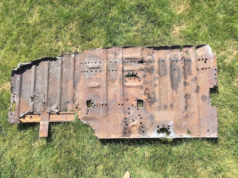
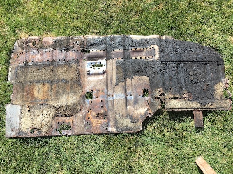
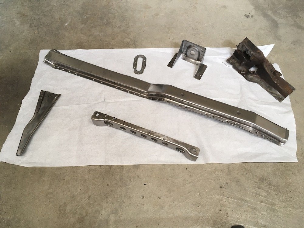
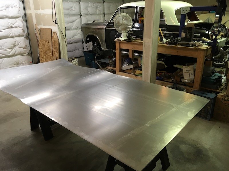
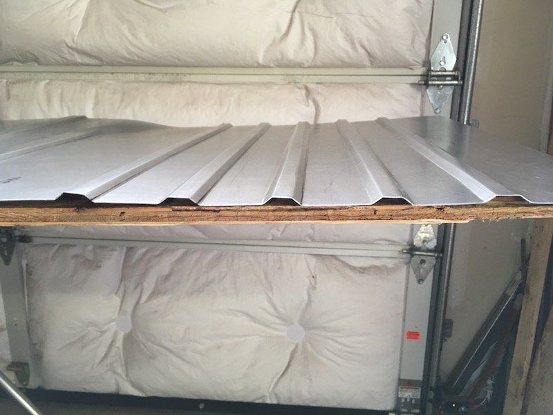
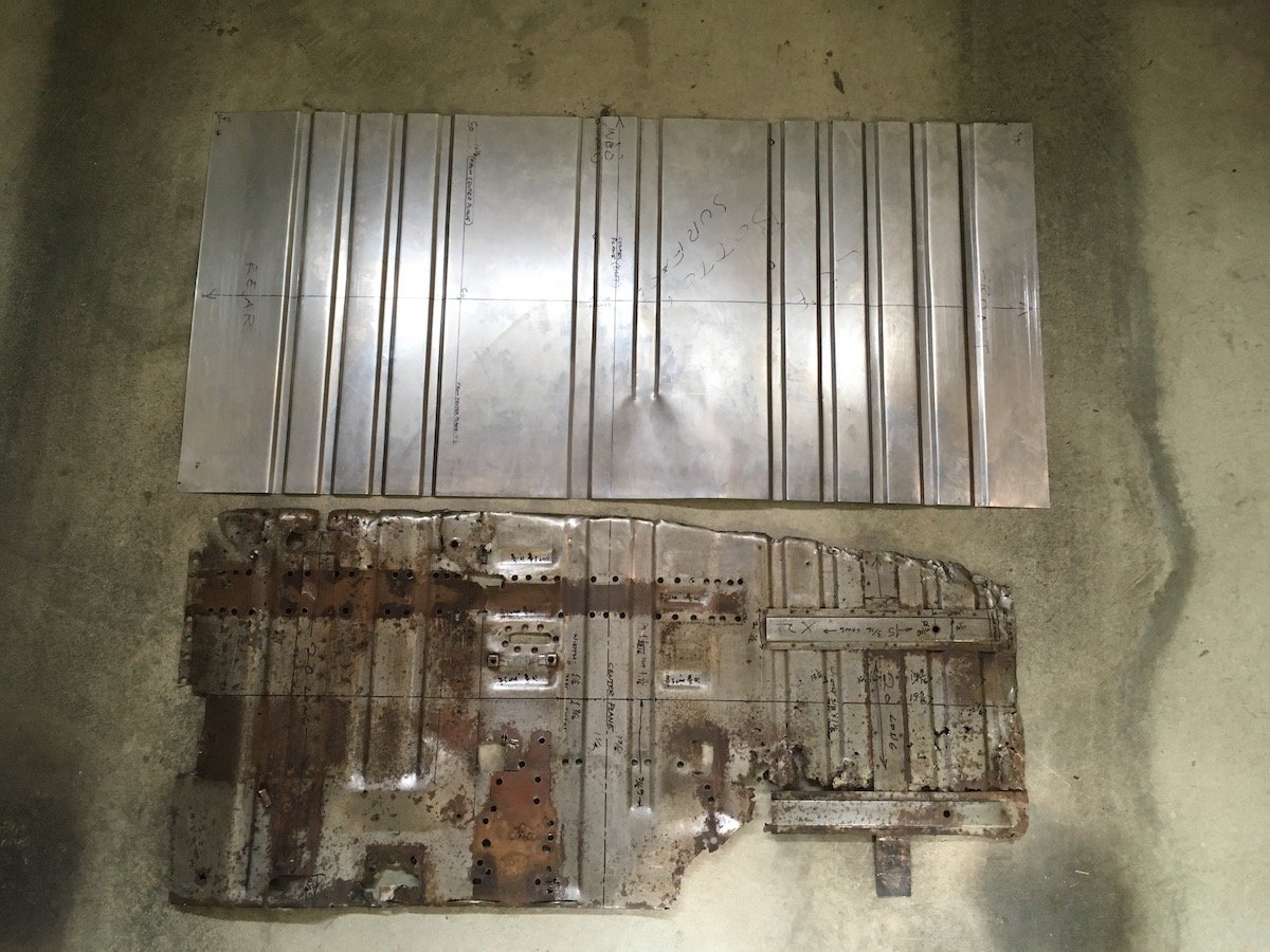
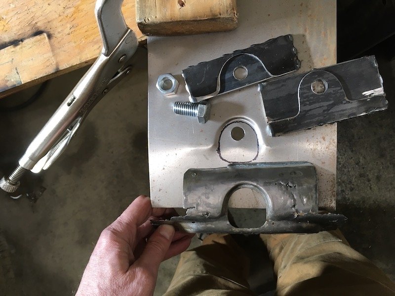
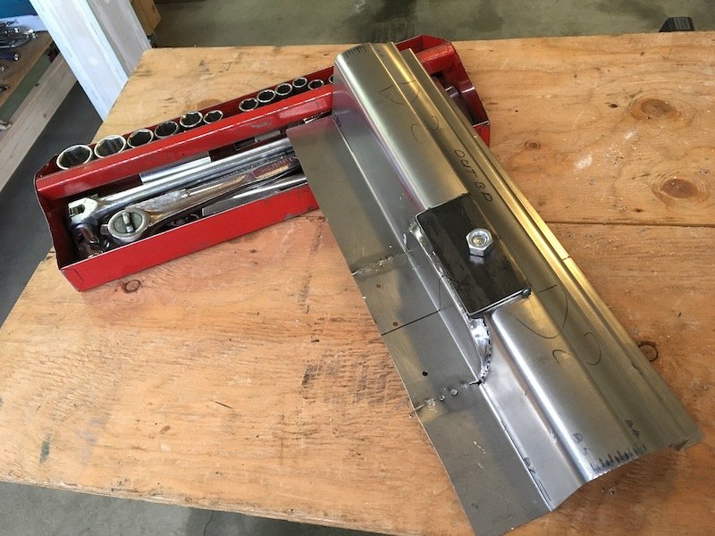
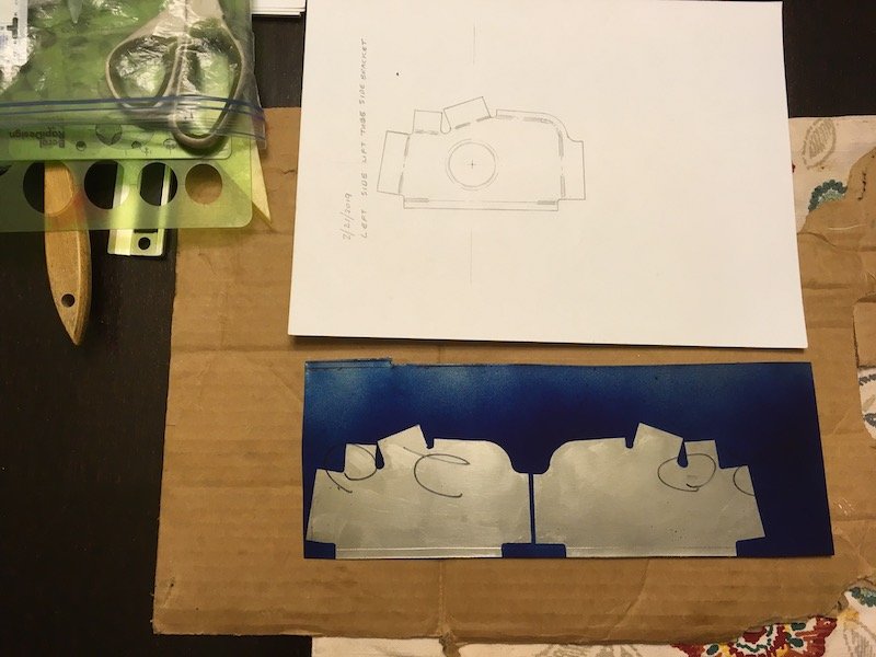
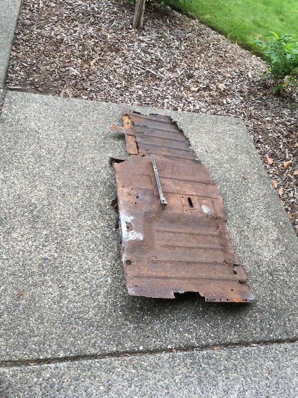
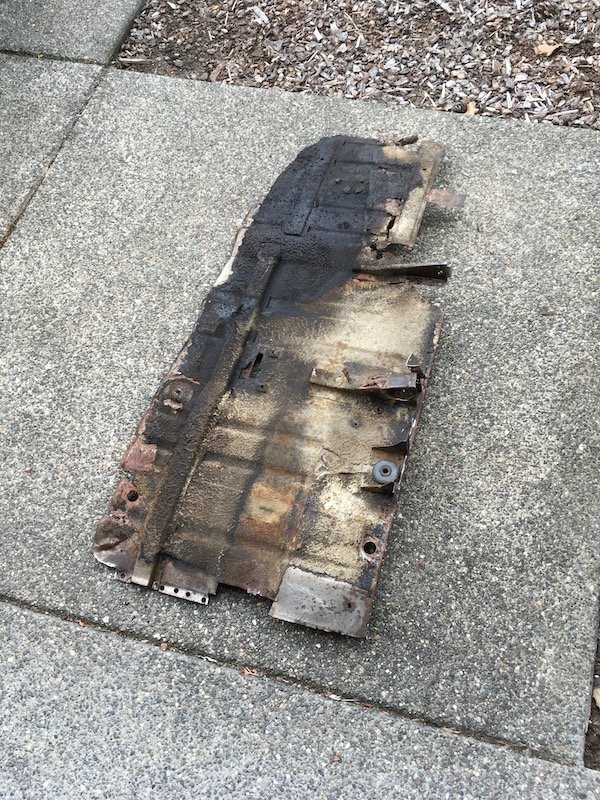
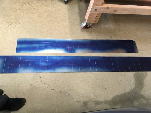
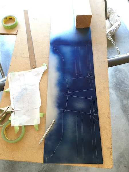
Back to work on reproducing the '61 310 Bluebird left side floor pan. First, I drilled out the spot welds to all the bits I wanted off the original floor. Top side Bottom side My collection of saved and de-rusted parts; including the seat bracket, longitudinal stiffener structure, hand brake reveal, B-pillar body mount bracket, and a couple of other brackets that are too far gone but get in the way. Bought some more steel sheet. Four foot by eight. I cut out a 26 by 56 inch blank and made some corrugated steel with a bead roller Scraped most of the under seal off the old floor pan bottom surface, did some measurements and began duplicating what was left. The bottom surface was more useful for measuring since it was much less rusty than topside. I'm leaving an extra inch or more all around to accommodate fit and trim later. Side-by-side compare Now I have to figure out a way to form some of the 3D shapes around the where the B-pillar body mount goes and the shallow depression under the hand brake lever. Hammer form over a wooden buck? Or form separate parts, cut the floor and weld in? Still have lots of work to do. Discussion: https://oldschool.co.nz/index.php?/topic/60267-marts-pl310-61-datsun-bluebird-sedan/
 8 points
 -
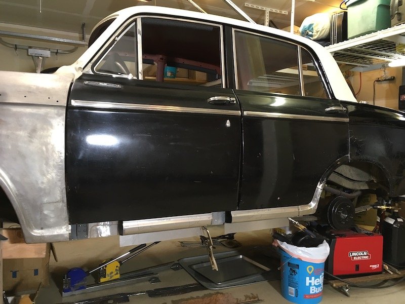
Raised it back up to get the outer sills painted white and straightened up and a few bubbles around rear guards seam tidied up. Struts have been crack tested, camber adjustable rear subframe ready to go in with f series 3.7 clutch pack lsd. Just need to fix various oil leaks and fit 205/60 tyres somehow and then try my luck at getting it legal
7 points
-
Not one to let a nasty cold get in the way of progress, I did some more work on the TVR today. The first course of action for the day was to see how the car starts. After a couple of splutters and a bit of cranking (much less than yesterday), it fired into life. Not perfect, but better. I couldn't help myself and had to take it for a quick run down the road and back. This uncovered a couple of things. One, the steering wheel is WAY off centre (which I didn't know whilst trying to back up my driveway), and the brakes pulsate a lot. Hopefully, an alignment will sort the steering issue, and some hard braking might clear the brakes as I suspect they are covered in rust/dirt. On the plus side, it did go down the road in one piece. I didn't get out of first gear (very short road), but the clutch seems to work well. Its too wet outside to go further, with no wiper, and a very un-weatherproof roof. When I returned from my maiden voyage I wanted to have a look at the plugs. I only removed one, but that was enough for me. They don't look that old, but very black. Not wet which is good. According to my records, they are the wrong heat range and should be BPR5ES I'll grab some new plugs and swap them out. Hopefully, that sorts some of the niggles when starting and running. Not to be deterred, I pushed on with some other little jobs. First was to upgrade the radio to work with my phone, and crank some Spotify. It was a quick and easy upgrade. Aww yeah, A cassette adaptor I had kicking around for years (see, hoarding works!). Actually works surprisingly well and doesn't sound terrible. All speakers work, and the flash EQ works a treat This can stay for a bit. Does what I need it to do, although I need to work out how to get the antenna up so I can get FM stations too. It's not like I really need music though, the engine is music enough. With that success, I moved onto the next thing on my list. The dodgy headlight switch. Two things bothered me about it. First, the wiring was dodgy enough to need wiggling to work, and second, the switch was upside down. The icon was on the bottom, and the switch was up for off and down for on. The switch pulls out the front once the connector is removed, but there is also a white plastic sleeve that pushes off. The sleeve is to illuminate the icon via fibre optic cable, but mine isn't currently working. The reason for the wiring being a bit dodgy was that the connector has obviously suffered some high resistance and the plug housing is damaged, allowing the terminal to float freely I pushed it firmly into the connector on refitting, but I may need to close the terminal a bit to make it a tighter fit. I also need to look into using some relays to re-wire the headlights directly and take the load off the switch. The switch its self had some minor corrosion on the terminals, but nothing a quick scrape with the screwdriver couldn't sort And refitted the correct way around. Down for off, up for pop-ups UP. The next thing that bugged me was the interior light switch... which seemed to be missing everything but the surround. The interior lights didn't work. I removed the surround and found the guts of the exploded switch had been pushed down into the center console. I carefully fished the switch block and connector out. The rest of the springs etc are stuck down there and can stay there until the console has to be removed You can see a good example of the black wiring in this car. Each wire is black, but does have a coloured collar at each end to identify it. Its not actually that bad to work with, but coloured wires are still preferred. Using the handy diagram I checked which terminals did what on the switch Obviously the two bottom ones are a joint +12, and the two other terminals are either "door open" or "on" settings (grounds to turn light on). I tried bridging them with wire and got nothing from the lights. I popped one of the lights out to check the bulb (there was one, it's removed in photo) The bulb looked good, so out comes the multimeter. No power at the light when the switch terminals are bridged. No power at the switch +12 terminals. Hmmm. Ok, what's upstream of the switch? The fuse. I had checked the fuses visually yesterday and they all look good, but something was obviously up. Interestingly I note that fuse 6, which powers the interior lights, also powers the hazard lights, which also are not working. Interesting. This is the fuse and relay box. Lovely. Fuse 6 is the red one about halfway down. It wasn't blown, and the multimeter said I had power on each side of the fuse. The power comes into the fuse on the RH side of the photo and out on the LH side, through the fuse. I disconnected the wiring, removed the fuse, and cleaned everything up. There was some corrosion in the terminal, and everything is very dirty. The result was this Hazard lights! A handy thing to have on a British car. Which also means, I now have power to the interior light switch. I popped an LED bulb into the holder, and bridged the terminal Ooooooh, light. Only one was working, so I jumped onto the passengers' side, popped the light out, and found that the wire hanging under the dash was from that light. I popped another LED bulb in that one, reconnected it and BAM, let there be light! Because the switch was buggered, and there was no point in finding another. It only operates these two "knee" lights, so when am I ever going to need to set them to "on", and they are LED so no point in turning them "off" when they turn off when the doors are shut anyway. I decided to bridge the terminals and leave it. I made up a jumper, using a pair of specially modified (squished in a vice until they fit) bullet terminals and some wire. To make it pretty, durable, and safe, I wrapped the lot in tape and then stuffed it into the center console TVR-Parts still sell the switch blanks, so I'll grab one of those and replace the interior light hole with one of those Unfortunately it wasn't all quite straight forward. The door switches weren't quite playing ball. The passengers side wasn't hitting the pad on the door correctly so wouldn't trigger the lights to turn off when shut, and it turns out the drivers side one had been unplugged. I swapped that over, so the passengers side is unplugged, and the drivers is now plugged in and working correctly. So, I now have sweet interior lights, and working hazard lights. Isn't it inviting? Love the warm white LEDs. Much better than the usual cold white, or incandescent bulbs. Also puts a lot less strain on the wiring and battery. Its small things, but in the world of British cars, it's a big victory to have things working.6 points
-
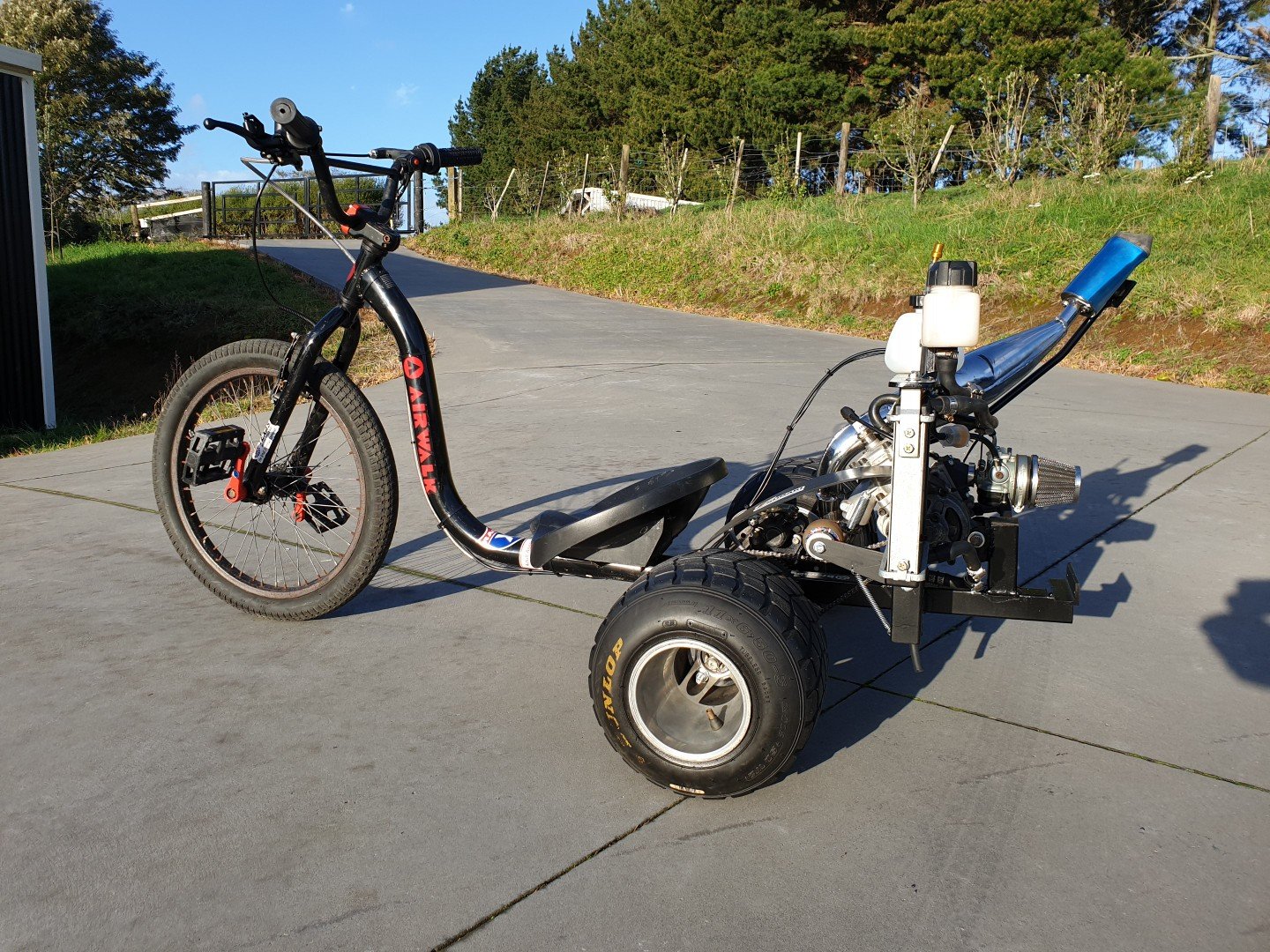
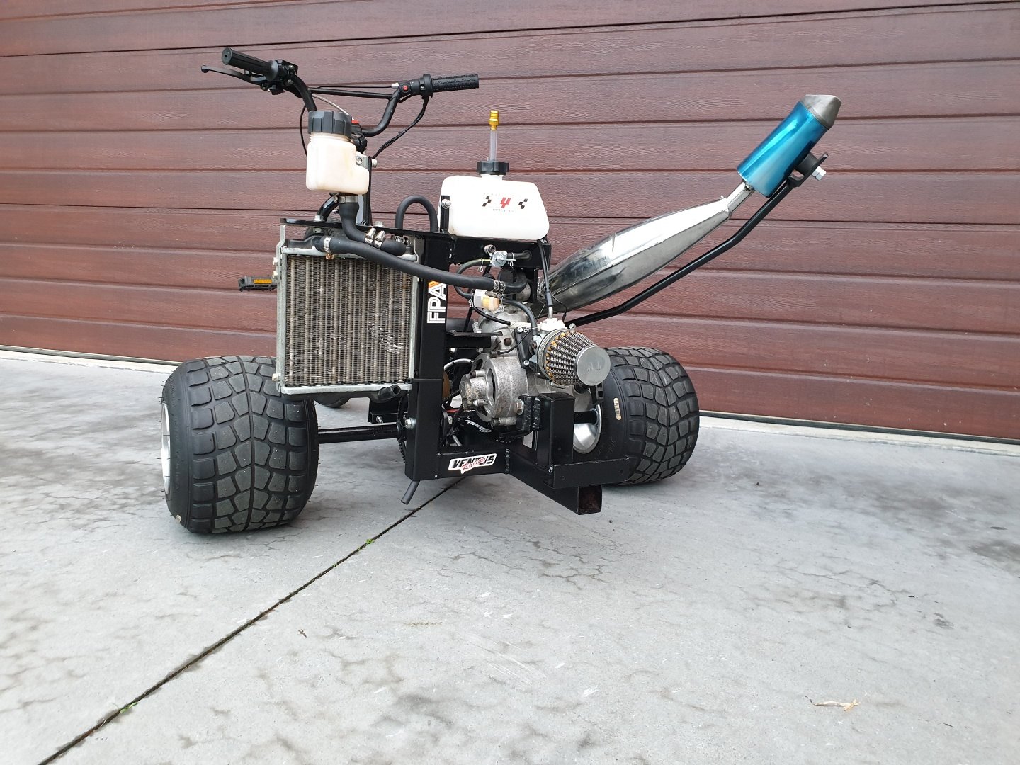
The crazys in the workshop have been at it again....
5 points
-
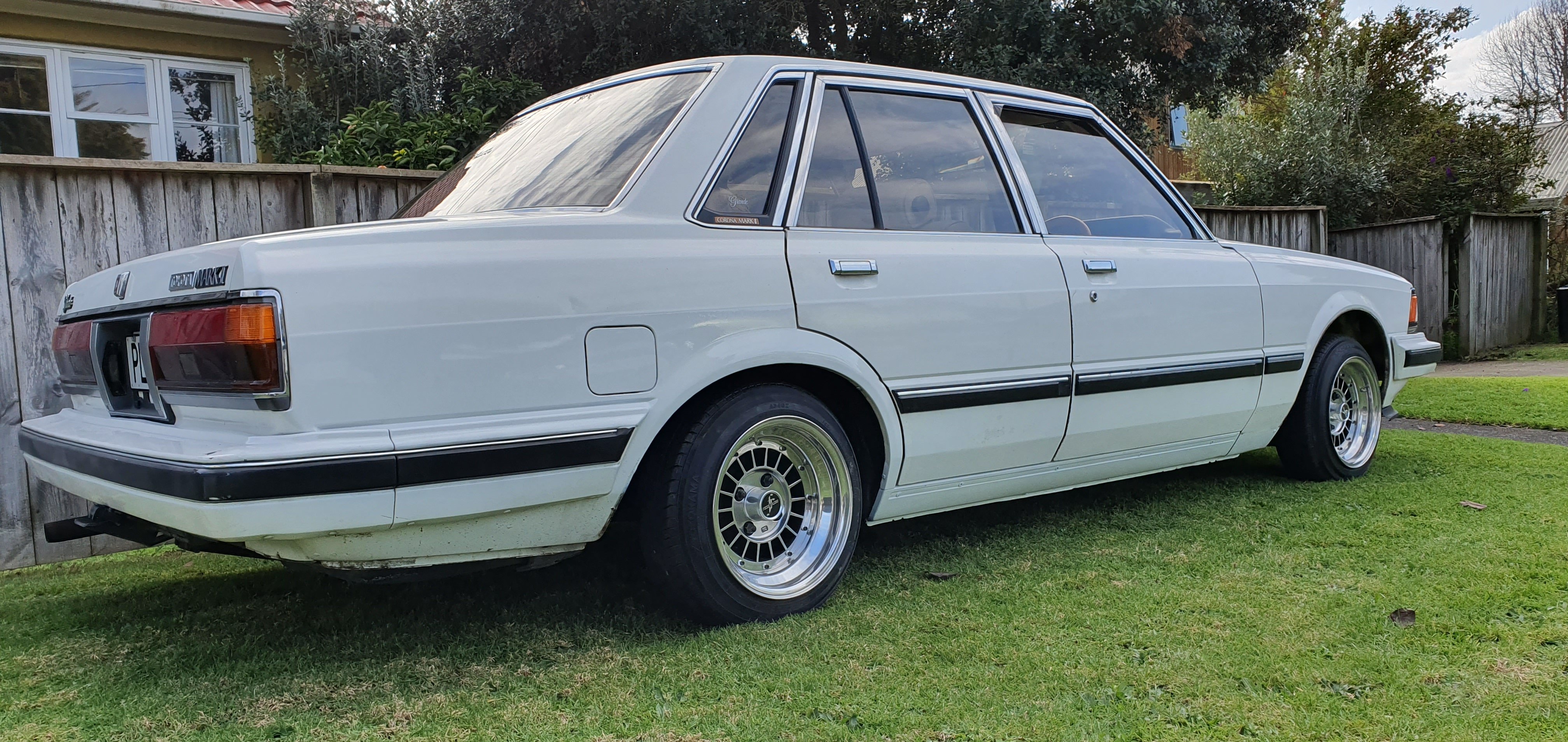
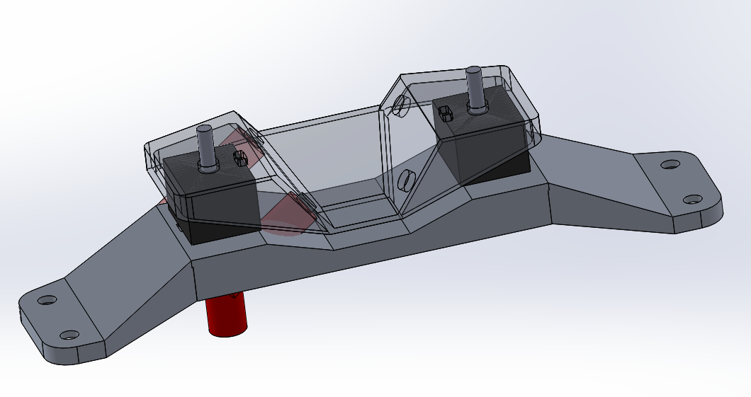
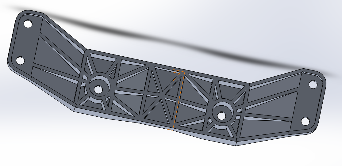
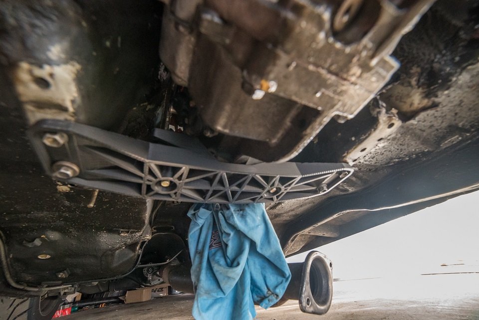
Slow progress, because winter time insanity. Made a prototype for a new gearbox crossmember/mount arrangement. That uses much stiffer bushes and ends up with waayyyyy more ground clearance than the big standard mount. Also, if I got it cast from aluminium the entire assembly is lighter than just the rubber bush part from the standard setup. win. Not sure how to make the final version yet, but it's good to have the gearbox sitting in the right place. And have a decent set of accurate dimensions for making a proper one. Hopefully soon figure out my driveshaft and exhaust situation. I'm on the lookout for a standard 2-1 part of an Altezza exhaust if anyone's got one kicking around?
5 points
-
So now here we are six months later and I've come to my second of two one week holidays for the year. This whole time I've still been mentally working on the car, thinking through all sorts of different problems and making plans and drawings along the way. Now I've had some time off from school, I made a trip back up home and put one of these plans into practice. However, before I can get into that, we have to go through a little story time first... It's long been playing on my mind the fact that I'd still not fully completed the V6 RWD conversion. Sure I'd made the adapter plate, engine and box mounts, intake setup, and sump etc, but the actual connection between engine and gearbox was still missing. The flywheel and clutch situation has been through a few revisions, both in my head and in physical work. You may remember from these posts: that I planned to use the standard V6 flywheel with an extra ring added to increase the outer diameter to take an RX8 ring gear as well as a spacer to bring it out the correct distance to take run the RX8 clutch and pressure plate. After making the spacer (which if I'm honest now I wasn't particularly happy with my workmanship and tolerances anyway) I found that the RX8 friction disk wouldn't work with the V6 flywheel or pressure plate, meaning I would have to adapt the RX8 pressure plate to the flywheel. So upon taking it to the machinist to get his opinion on making the adaptations for the larger ring gear and pressure plate, we found that pressure plate bolt holes would end up directly on the junction between flywheel and adapter ring. This was doable but it was far from ideal. Also, the labour involved would have cost similar amounts to a fully custom flywheel anyway and thus the whole plan was put on hold for a while. You may indeed have noticed this in the complete lack of a mention of the clutch and flywheel in the following posts. And so came about my next plan. Ever since reading @yoeddynz's viva thread, I'd been pretty keen on using a lightened flywheel to help unleash the engine's propensity for revs. Luckily, this was going to let me kill two birds with one stone. I'd decided long ago that I wanted to keep everything inside the bellhousing exchangeable with standard RX8 parts. This will allow me plenty of potential clutch upgrade options in the future. With that in mind, I went looking for RX8 lightened flywheels. Almost exclusively, lightened rotary flywheels are designed to bolt up to the automatic counterweight, rather than using the integral counterweight cast into the standard flywheels. This made my life much easier. Now I could make an adapter that picks up the six holes in the flywheel, spaces it the correct distance to use the standard RX8 clutch and pressure plate, and bolts to the end of the crank like the normal V6 flywheel. Essentially I can make a counterweight emulator. The next step was to decide the material to make my adapter out of. I could of course just use any old steel billet lying around the shop but my fondness for my feet kind of convinced me not to go that route. So I looked at what material is usually used for steel lightweight flywheels and found that 1045 is common. I figure if it's strong enough to take the forces on a whole flywheel, then it should be well strong enough for my much smaller diameter adapter. Next, I had to take measurements of everything and design the actual adapter itself. And this is what I came up with. You'll have to thank the American's for building the majority of commercial aircraft in service for my use of imperial measurements. Almost all the tools used in the industry are in imperial and because of that, all the tools I had available at school are as well. Anyway, according to these dimensions, the ring gear should end up in the same position as the RX8 relative to the bell housing face and starter, and therefore the rest of the clutch system should work as normal as well. With all this done, I could finally go home and get stuck into it. Step one, of course, was to get the raw material into a useable state by facing it up and generally roughing it out. Thank god for power feeds and tungsten carbide tools. Next, I turned the recess that fits over the end of the crank concentric to the outer diameter of the material. With that done, I turned the piece end for end and dialed everything back up in the four jaw to turn the spigot that that flywheel runs on. This is also concentric to the outer diameter and, by extension, the recess as well. This is obviously crucial to avoid vibrations and undue wear on bearings and so forth. You'll also notice the stepped section on the front of the spigot. This is designed to fit the inside of the standard flywheel for reasons that will become clear later on. With those surfaces all machined, the crucial dimensions are done and I can have a nice big exhale. This means I can move on to less nail-biting procedures. One thing I did learn from the first spacer I made way back in the day is that measuring and drilling PCDs is a right royal pain and very difficult to do accurately with the tools I have available. So this time around I decided to forgo any and all measuring of PCDs entirely and use a far more analog method. I already have the PCD that I'm trying to match. Why would I not use it to guide my drill bit? So with that in mind, I made up some bushes to guide the pilot and tapping drill and protect the aluminium flywheel. Next, I clamped the flywheel and adapter together and shifted everything to the drill press. You can see the bush already in place in this photo. Once I had the first hole drilled to size, I tapped it to M10 x 1.25, which is the thread used by Mazda on the automatic counterweight that this flywheel is designed to bolt to. With the first hole tapped, I bolted the flywheel to the adapter, which let me get rid of the whole clamp setup and drill the subsequent holes much more simply. I used a similar setup for drilling the crank bolts too. I wasn't nearly as worried about damaging this flywheel since I won't be using it once it's done its jig job, so I only used a bush for the pilot drill and just threw the final drill through using the flywheel itself as the bush. Now that all the holes were drilled I decided I ought to check my tapped threads for strength now, rather than do all the rest of the work just to find that they strip as soon as I try to put any torque on them and junk the workpiece. So I throw the first bolt in and torque it to the high limit of the 32 - 45 ftlbs recommended by Mazda for the flexplate bolts. It goes tight, tight, tight, still tight, still turning, still turning, shit. I figure its stripped and fucked. So out it comes and sure enough, the bolt thread is gone burgers. However, the female threads are still pristine. Stoked. So in goes round two. Tight, tight, tight, still tight, still turning, still turning, shit. Again. So, out she comes and another bolt failure. This time it stretched the crap out of the bolt but still left the threads perfect. Third time was the charm though and all the threads eventually took the torque like champs. Guess that teaches me for using the first bolts I find lying around. Finally, I put everything back into the four jaw and faced something like 15mm off the spigot to bring it back to flush with the flywheel face and finalise the outside dimensions. Here you can see me checking the runout of the flywheel when mounted and it was well well within the 0.008" tolerance specified by the Mazda service manual. Finally I bored the recess for the spigot bearing. I decided to use the MX6 spigot bearing, mainly because I had one available, but also because it fits the RX8 input shaft perfectly, and it was much easier to machine the larger bore for than the much smaller stock roller bearing used on the RX8. It's a very light press fit, able to be tapped home with a mallet just like the fit in the original V6 flywheel it came out of. Finally, after two straight 14 hour days on this thing, I was ready for a dry fit. I used the longer crank bolts that I bought for the first spacer which gave me shed loads of thread engagement, as well as a couple of M10 bolts I had lying around for the flywheel itself. I'll get some proper high tensile ones later on. Next was the clutch and pressure plate which I eyeballed the alignment of and used some more M8 bolts I had lying around. Finally, I muscled the gearbox around and offered it up. With the engine and box somewhat leveled the input shaft slid right in and home over the adapter plate dowels. A couple of bolts later and I stood back to admire my handiwork. It is a beautiful thing indeed. I couldn't help myself at this point and threw a driveshaft in the back end and a ratchet on the front and low and behold we have drive!! I have to apologise for the photo quality at this point. I think there's a smudge on the inside of my lense somehow and it wasn't having a great time with the fluorescent lights at 1:30 in the morning. I ran it through all the gears and checked the disengagement with the BFC in the bottom of the frame, and it does indeed stop spinning the driveshaft with the clutch in while still having a small amount of wiggle to the arm when out. I also checked the starter engagement with some white paint pen and it looks to be exactly where the existing wear marks are on the starter gear. I'd have loved to hook up a battery and some jumper leads to spin it over with the starter but I did end up running out of time. With all said and done I am absolutely stoked with how everything worked out. My measurements and calculations were apparently right on the money, and my machining workmanship and tolerances are leaps and bounds ahead of the spacer I made initially. The final setup for my adapter situation comes out to this: Custom 12mm steel engine to gearbox adapter plate of my own design Custom 1045 steel flywheel adapter of my own design Aftermarket RX8/Turbo RX7 lightweight aluminium flywheel 6 speed RX8/Turbo RX7 clutch and flywheel MX6 spigot bearing Stock RX8 clutch arm/release bearing If you've made it this far though what was a whole afternoon of typing then thank you very much for reading. I'd appreciate any comments or feedback on my discussion thread which you can find here: That's it for now. Hopefully won't be another six months before the next update but we'll have to see what happens. Cheers.
5 points
-
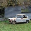
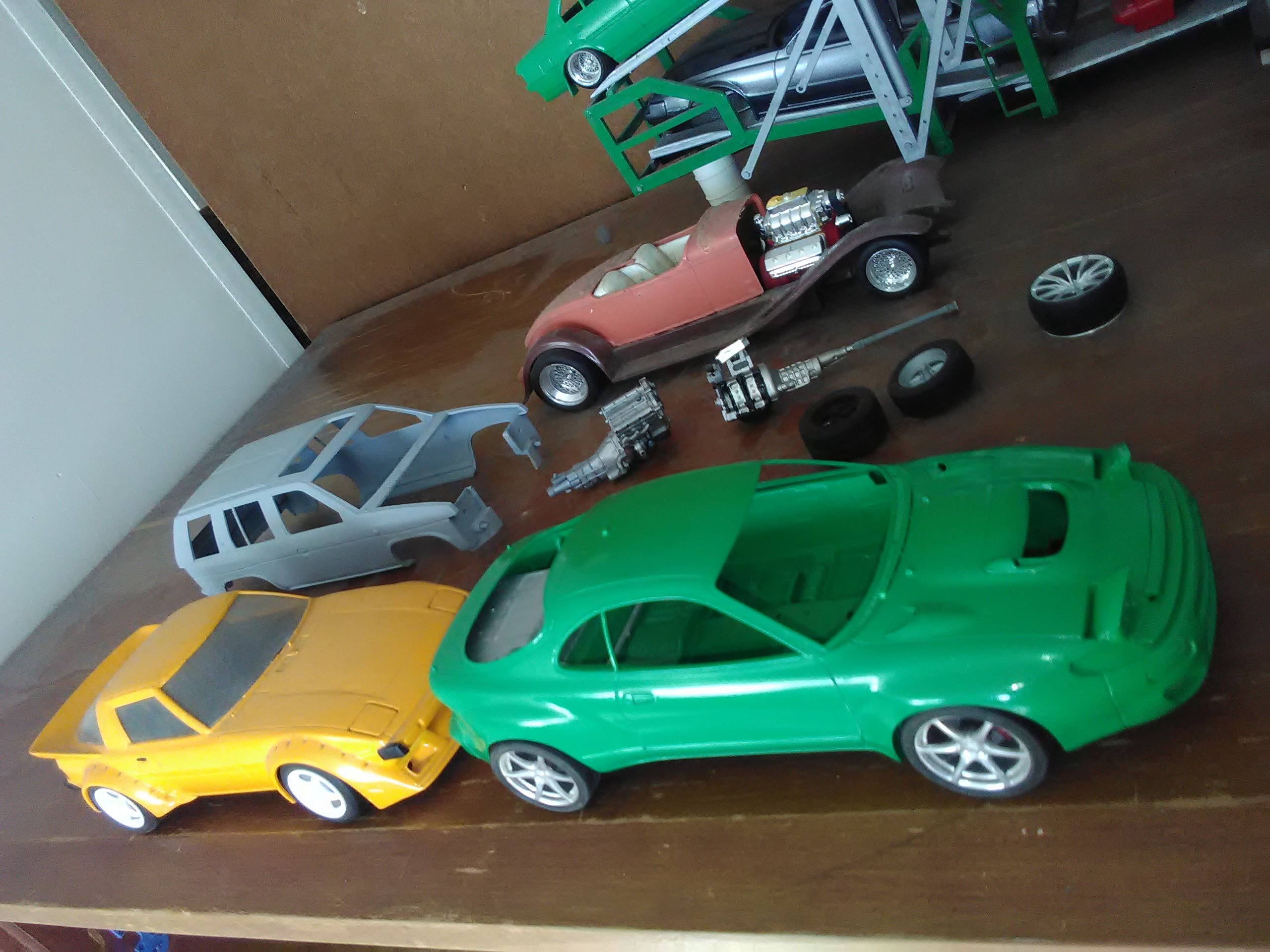
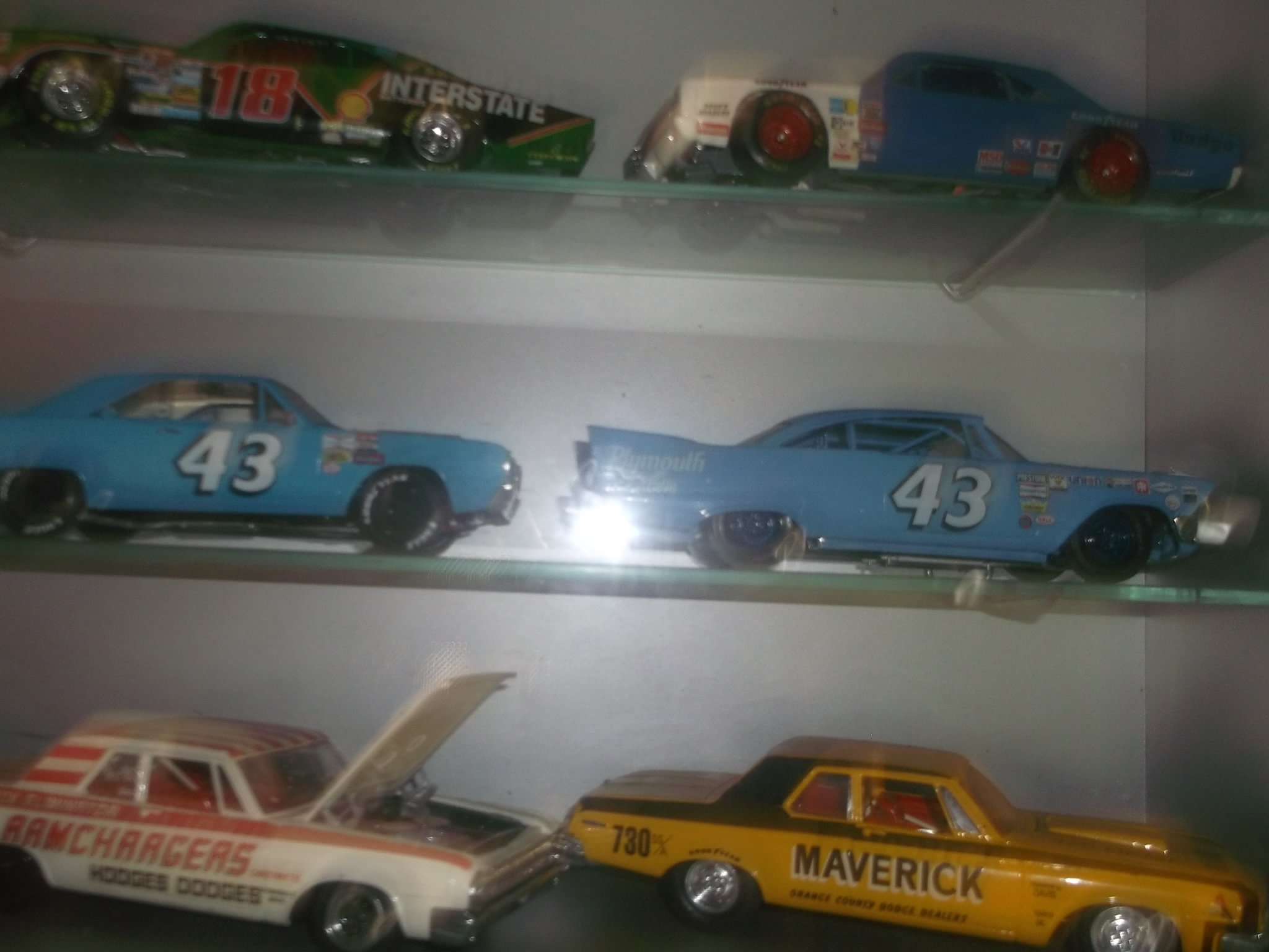
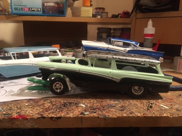
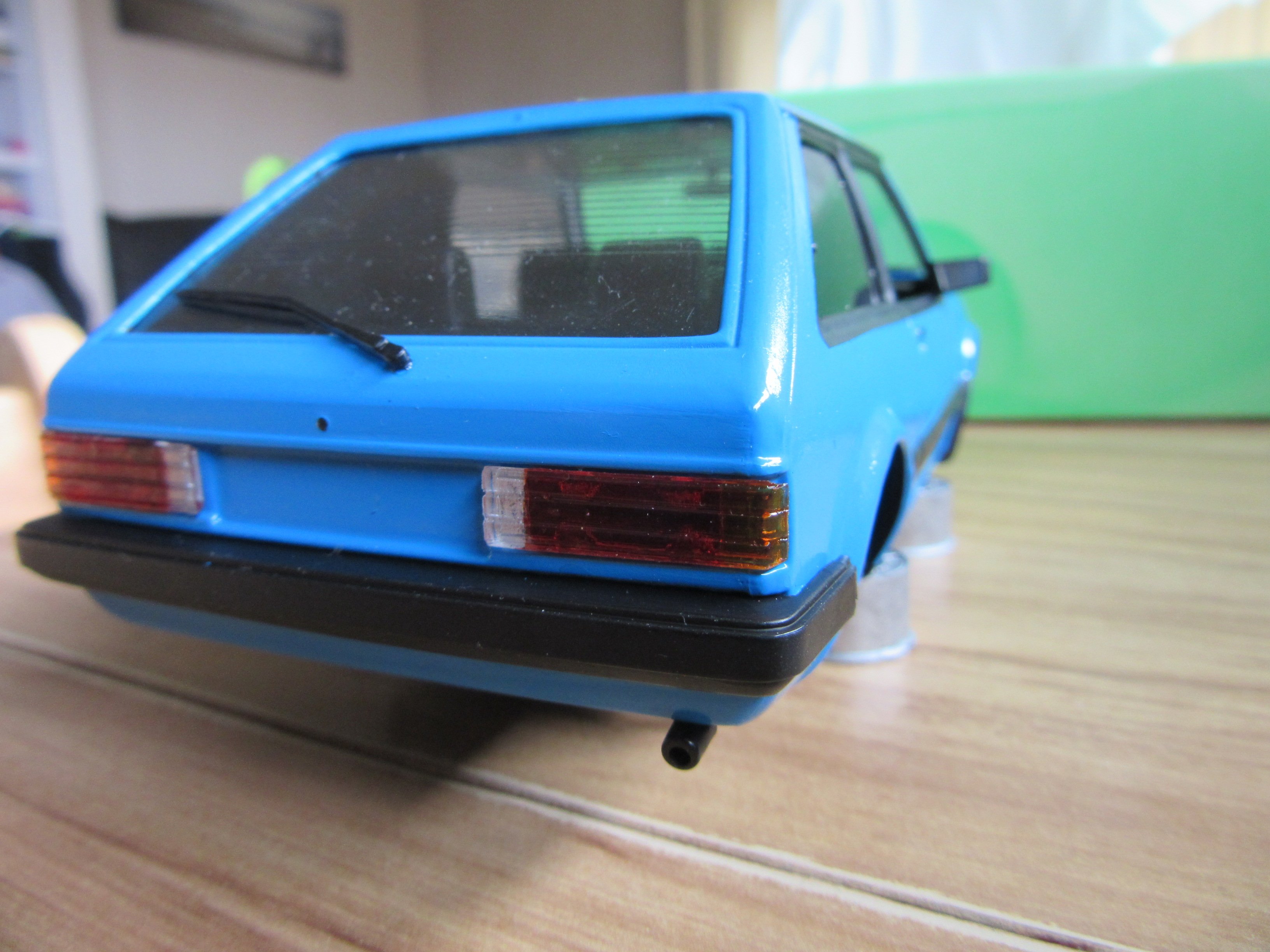
I'm trying to stay interested in doing 1:24 scale models, but the end result seems to be much more appealing than the actual building, but I have several kits to build, so must keep going. Here's a couple pics of my latest build: And here's what I'm currently working on and I cannot wait to have it finished!4 points
-
Well, it happened again. Somehow awesome old British cars that need loving find me, and of course who am I to turn them down? This car has a bit of a weird story, but I guess it adds to the history of it all. It all started when I had the M328i listed on Trademe, back in March, and in amongst all the useless time-wasters asking me dumb questions, I got asked if I wanted to swap the black leather vaders for white leather seats from another M3. Of course this was a no, white leather is one of the worst wearing colours in the E36. The fellow wasn't done there though, he wanted my seats. The next question he asked on my listing immediately had my ears perk up, and suddenly I was intrigued. Yes, that's right, a TVR. After a bit of googling I worked out an 80s TVR would be a Wedge. Not the most loved TVR, but I like them, and any TVR is a good TVR in my books. It's 80s, it's British, how bad can it be? Of course I was interested, and let him know. Later that night I get a call and discuss the car. Its been off the road for a few years getting some work done at the "local" TVR specialist, in Auckland. Ok, no problem, except the owner is down in Christchurch (about 1000km and a large body of water away from each other, and I'm somewhere in the middle of that). It turns out that he wanted my car, because he was buying a convertible E36 M3, and wanted to swap my black leather into it. He also had thoughts of "Trevors last drive" by flying up to Auckland, picking up the TVR, driving it down to me, swapping to the M3 and for him to continue on his way down south. As I found out later, this would've been a big ask for the TVR. We discuss the ins and outs, and I'm recommended to contact the specialist and discuss the car. I give the specialist a call and discuss the car. Apparently it's all sorted, and basically ready to "fly through" a WOF and to hit the road. Its had various work done, including most of the hard work like suspension. He noted it does have an issue starting, which is possibly down to a failed fuel accumulator, but does run and could be driven onto a truck. His description of the car was that its a good solid, tidy car, but may need some carpets as they are a bit worn. I was very interested, but needed photos to see what condition it was in. Ok he said, he will try and sort some for me. To cut a long story short, I tried for months to get photos of the car, with every reason under the sun for not getting them from the specialist. On the other side of it, the seller of the TVR decided not to buy that M3, and couldn't find one he wanted, so no longer had a need or want for my car. I let him know I was still interested in outright purchasing the car but would need photos. Both him and myself followed up with the specialist, to no avail. Just before I went on holiday at the end of June, the BMW sold, but I still had no proof of life that the TVR even existed, so just left it hanging whilst I chilled out in the UK (more on that in a later post). When I returned, I already had a list of cars on Trademe I wanted to look at. I had basically given up on the TVR at this point, as during the month I was away, still no photos had been sent. I looked at a couple of cars, including an Evo 4 (which I came very close to buying, but the second viewing showed too many issues, and the unmistakable smell of weed inside) and a C55 AMG (nice car, if a bit dull). I wasn't quite set on them, but noticed that the TVR specialists website had been updated, with new photos, and what happened to be dead center in the photos, but a silver Wedge! Well, there was my proof of life I guess; the car did exist! I contacted the owner and confirmed the car was still for sale, and then did the stupid thing; making an offer for the car as it sits, without so much as a real photo. Offer was accepted, and a call was made to the specialist to make sure no money was owing, that the car could come with the spare parts, and that it would drive onto the truck.... oh wait, what's that, it suddenly doesn't run but you will "try to get it going"... I pushed forward anyway, sending my hard-earned money to the seller, and booking my preferred transport, letting him know that the car doesn't run but the specialist will "try" to get it running. After a long week of waiting, this showed up this morning. Yes, that's the proper good fella Brent from Classic Towing dropping off yet another project to me. Can't recommend him enough, as even when things go a bit pear shaped, he has it all under control, and he loves weird cars almost as much as I do. My first question to him was "did it run?" to which he replied with a no, and tightened the winch ready for laying the bed flat. Such a cool truck, it lowers the bed right off onto the ground. This is half way down Brent pushed the car whilst I jumped in and steered it carefully into the garage. This was harder than you would think, being that it was raining on the outside, and inside of the windscreen, and the wiper didn't work (well, it's not even fitted). We made it safely into the garage though. The brakes work, which is something. So, what is this weird little thing? A 1980 TVR Tasmin 280i It's more or less a Ford Capri in a fibreglass body with tube-frame chassis and some weird and bespoke parts. Powered by a 2.8l V6 Ford Cologne engine topped with Bosch K-Jetronic mechanical fuel injection, backed by the latest (for the 70s) in Ford 4 speed manual gearbox technology, and driven via the rear wheels through a Jaguar XJS diff with spiffy inboard disc brakes. The pinnacle of technology, and a real parts bin special. On the plus side it does get some pretty advanced gear for something that is the same age as my green Mini. Independent rear suspension, four wheel disc brakes, fuel injection, electric windows, bonded windscreen and a targa top convertible. It does have a lot of known quirks though, such as a multitude of wiring issues, a wiring loom that consists of only black wires (seriously), diabolical K-Jet fuel injection, and a dual fuel tank system that is no end of troubles. Anyway, this car is the 106th Tasmin off the line, and appears to be the 4th DHC (Drop Head Convertible) made (1st was a concept made from a chopped up FHC). Before the DHC was in production, the FHC (Fixed Head Coupe) was the TVR to have. The FHC was soon phased out though and only the DHC survived until the end of production, albeit with some big changes. Being a very early car, my one has some specific early only "features". The first, and most obvious, is that its a TVR Tasmin, not a TVR 280i. TVR dropped the Tasmin name later on and left the names to just be the displacement of the engine (280i - 2.8 V6, 350i - 3.5 V8 etc). A couple of other early features are the weird little mirrors hanging off the doors. Later cars changed to pods in front of the side windows, like a normal car. One of my favourite really early features though, has to be the gorgeous Stewart Warner gauges The later cars got boring, but arguably more readable (and probably reliable), VDO gauges. There is just something about the way the SW gauges are clocked, and the vertical odometer. So, now that the car has been delivered, how is it? Did i win the blind buying game, or get screwed? It's not as tidy as described, and it doesn't currently run. The battery was completely dead (to the point my ctek charger won't even detect it), but with a replacement battery the electrics are slowly coming to life again. Unfortunately, it leaks like a sieve and is full of water. I tried to dry as much as I could out, but the dehumidifer will have to do the rest. The roof seals will be the major contributor to this, as they are well buggered. The water ingress is what has ruined the carpet, it's literally rotting away. The boot, once I got it open, wasn't much better, with the lid being full of water and covered in condensation on the inside. The seats are in good condition, with no obvious rips or tears, as is the rest of the general interior. The wood grain has some cracks, but overall for a car I suspect spent a lot of time sitting outside, its in good shape. Apparently blue velour and vinyl stand the test of time. Bodywork is very good, with only some stone chips on the front. The rest of the paint appears to be good and will come up well with a polish. The top is also in good condition, with only some damage to the fabric on the removable section, and the rear window is very cloudy. Hopefully, I can polish that out, but it may need replacement. I don't know how the car is mechanically as it does not run. The previous owner advised (only after I had paid for it) that there is a strong fuel smell from the tanks when sitting, but it drove well otherwise. The fuel in the tanks smells like varnish, but cannot be smelt without opening one of the two fuel caps. I will need to drain this out and throw some new fuel in before trying to start. The starting issues could be a few things, but I will get to that in due course. One cool thing about TVRs is the convertible roof with a removable targa section. You can either have the roof up, down, or the rear section up but without the targa section, which fits into the boot (roof isn't locked in this photo, so looks a bit baggy) So that's the TVR. The plan is to get get it running, get a WOF on it and then take it to the British Car Day show in Feb. In between that, just take it out for some top-down Summer cruising. Oh, and keep fixing it. Can't forget that.3 points
-
Yeah something went wrong, 2 part epoxy will usually stick pretty good even to a poorly prepped surface. So using the data sheet for something like the protec 408 epoxy primer it says to sandblast your metal or sand it until clean and coat it. Says if you are using new sheet metal to use their acid wash (which is phosphoric acid) to remove the oils, read the data sheet for the acid wash it says to use steel wool to apply and wash with water so you are washing and scouring it, then wax and grease before painting. This is how I learnt from a couple restoration body work guys, backed up by the data sheets of most paint systems. Now epoxy is used as a sealer of old paint so it does stick to other shit and usually well. But you want to test it out and if you go all the way to bare metal I don't see why you would want anything else under it, especially a rust converter primer, they don't have the same adhesion as magic chemically cured 2 part epoxies. http://www.ppglic.com.au/uploads/tds/408 Epotec Epoxy Primer (2).pdf So for all applications its pretty much clean white sanded/scotch brite steel clean with wax and grease and then apply 2 part epoxy. If you have pitting or want to clean it then acid wash with phosphoric, neutralise with water. I would still key the metal up again with scotch brite after the acid wash to remove everything as you can get some residue if the acid wash got dry. Anything else is garbage IMO. Then for safety as said modern epoxy cures with polyamide, old school ones used amine or something toxic (not a chemist). So 2 part epoxy is very similar as other single stage paints as far as safety goes, ie don't breath it and avoid getting it on the skin and eyes. It doesn't have the extra death factor of polyurethane which cure with isocyanate, anyone who has sprayed urethane clear knows how deadly that shit smells.3 points
-
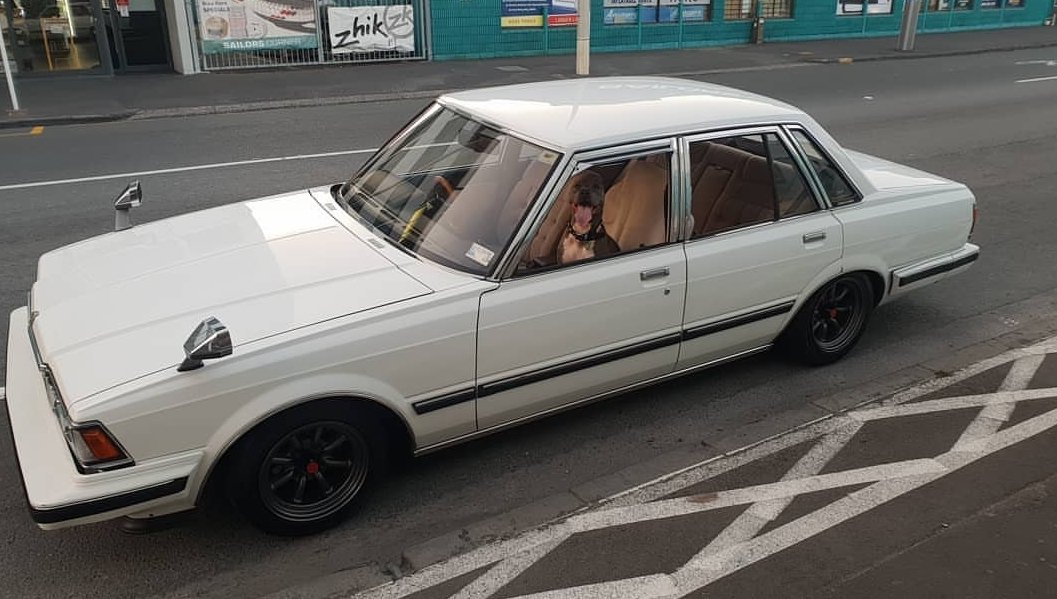
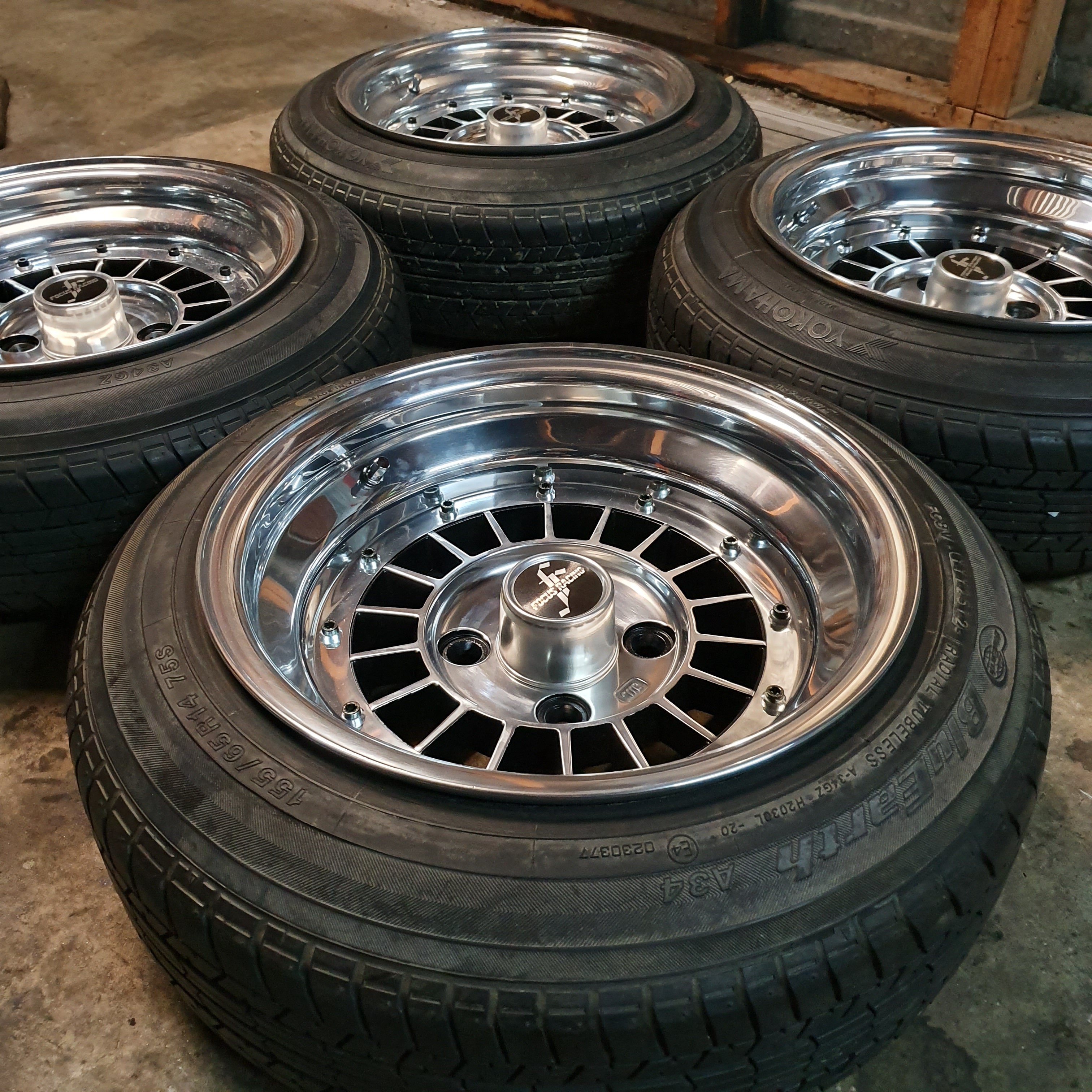
Resurrection from the 8th page! Lowered the front some more and was rewarded with a pink sticker in march Sold the watanabes and replaced with 7/7.5j focus spoke
3 points
-
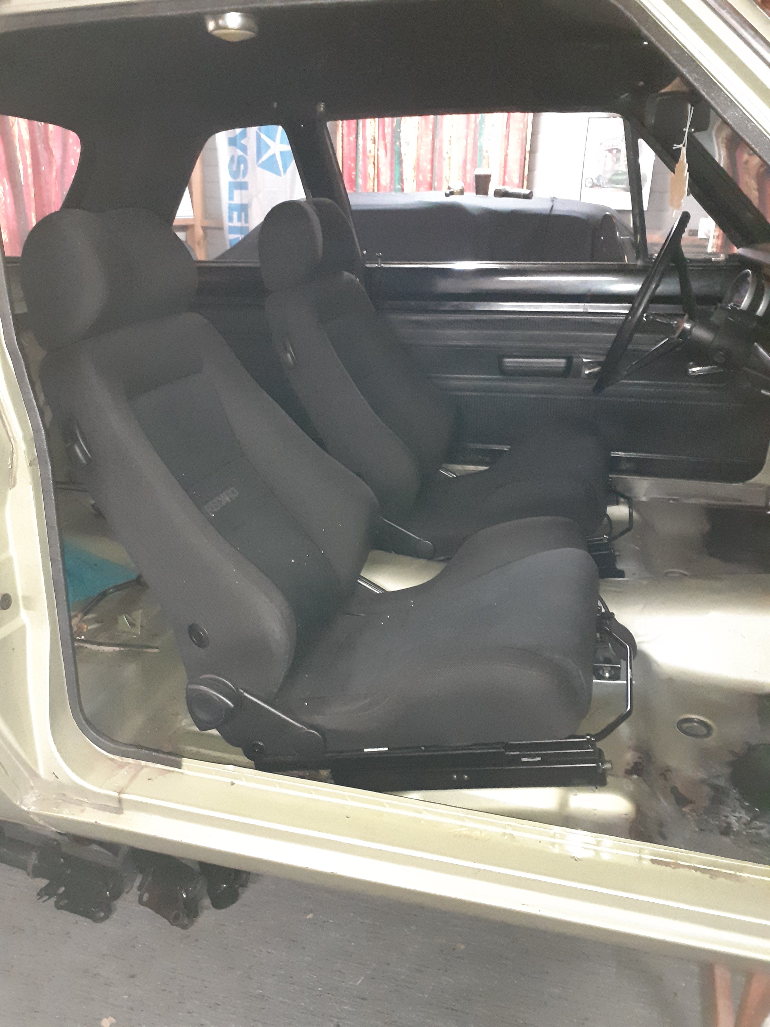
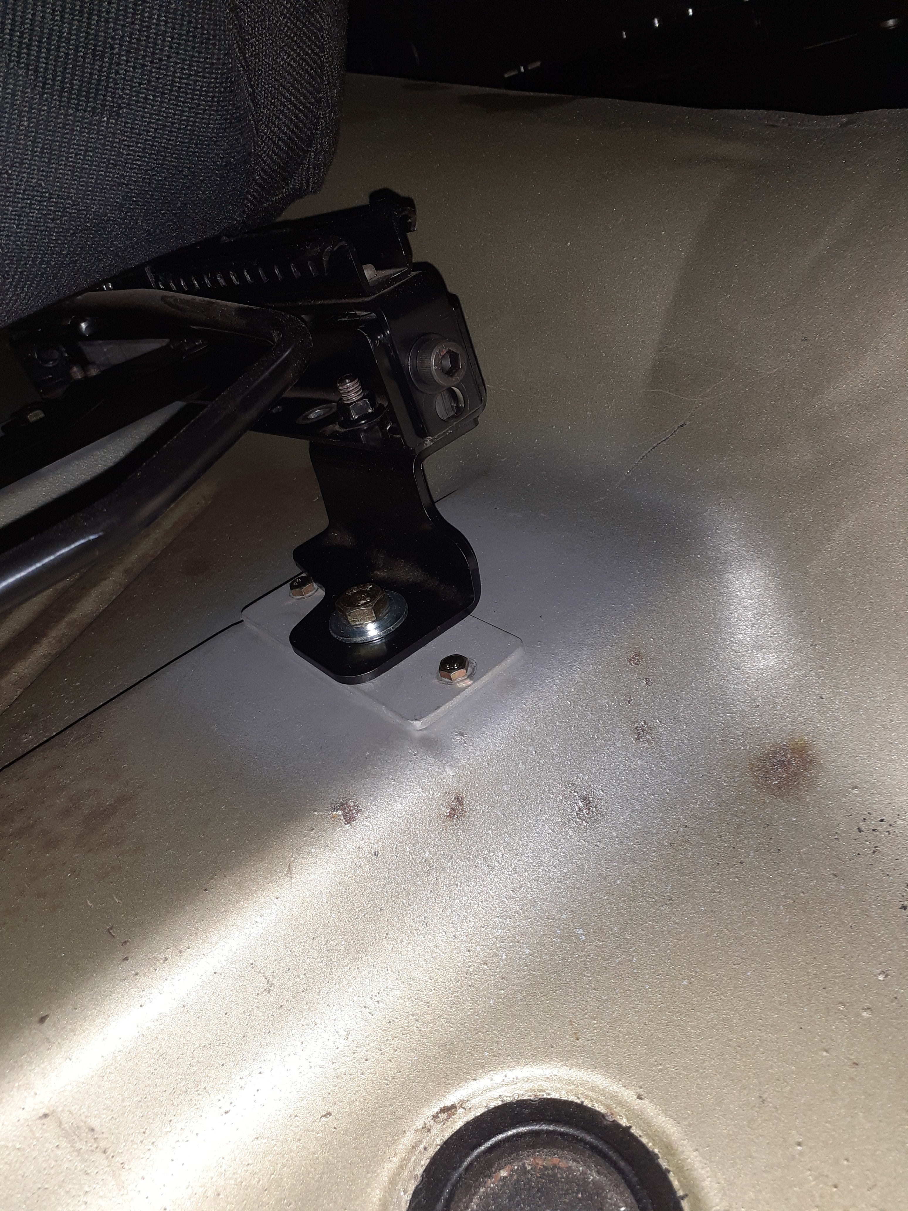
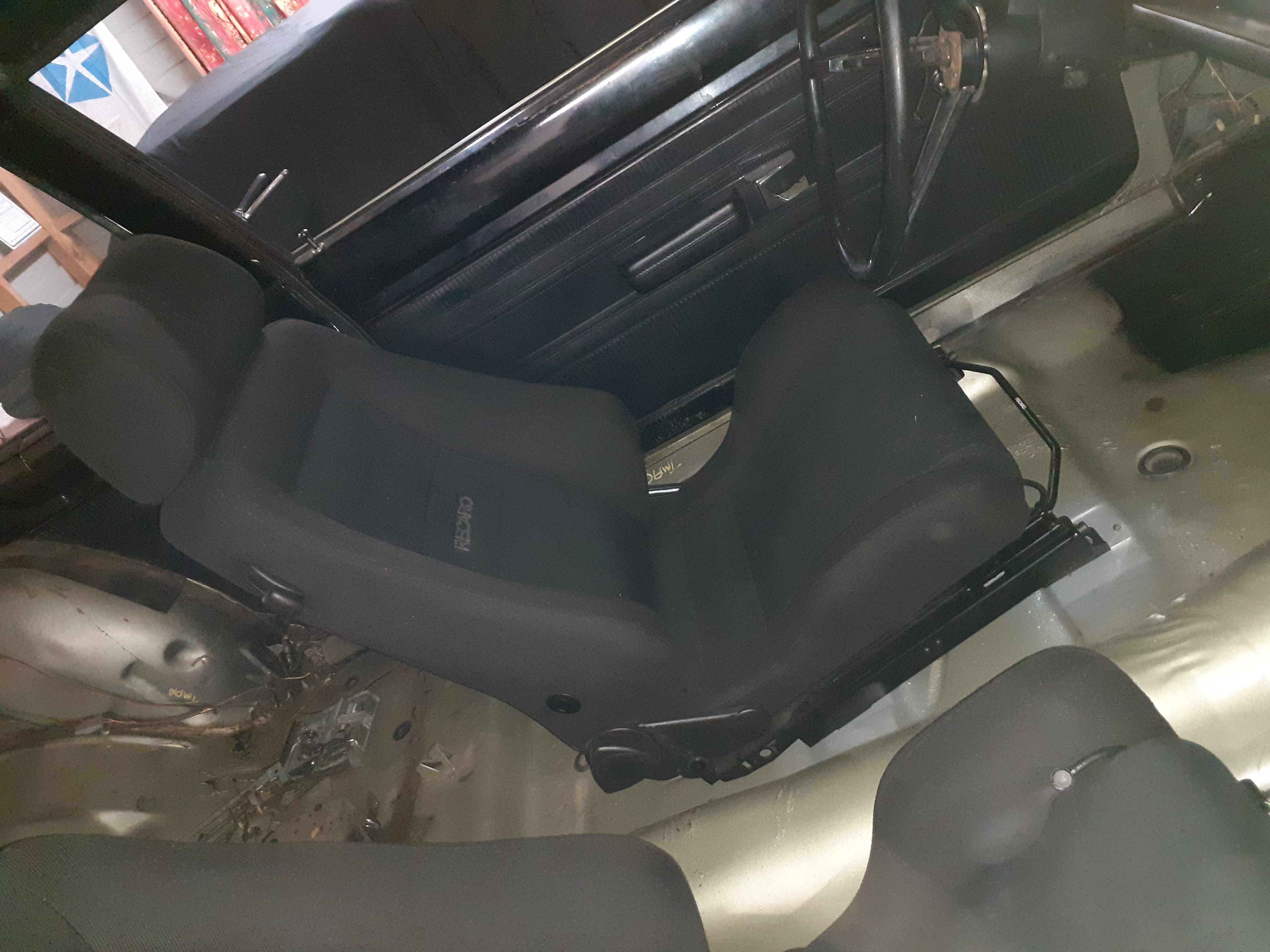
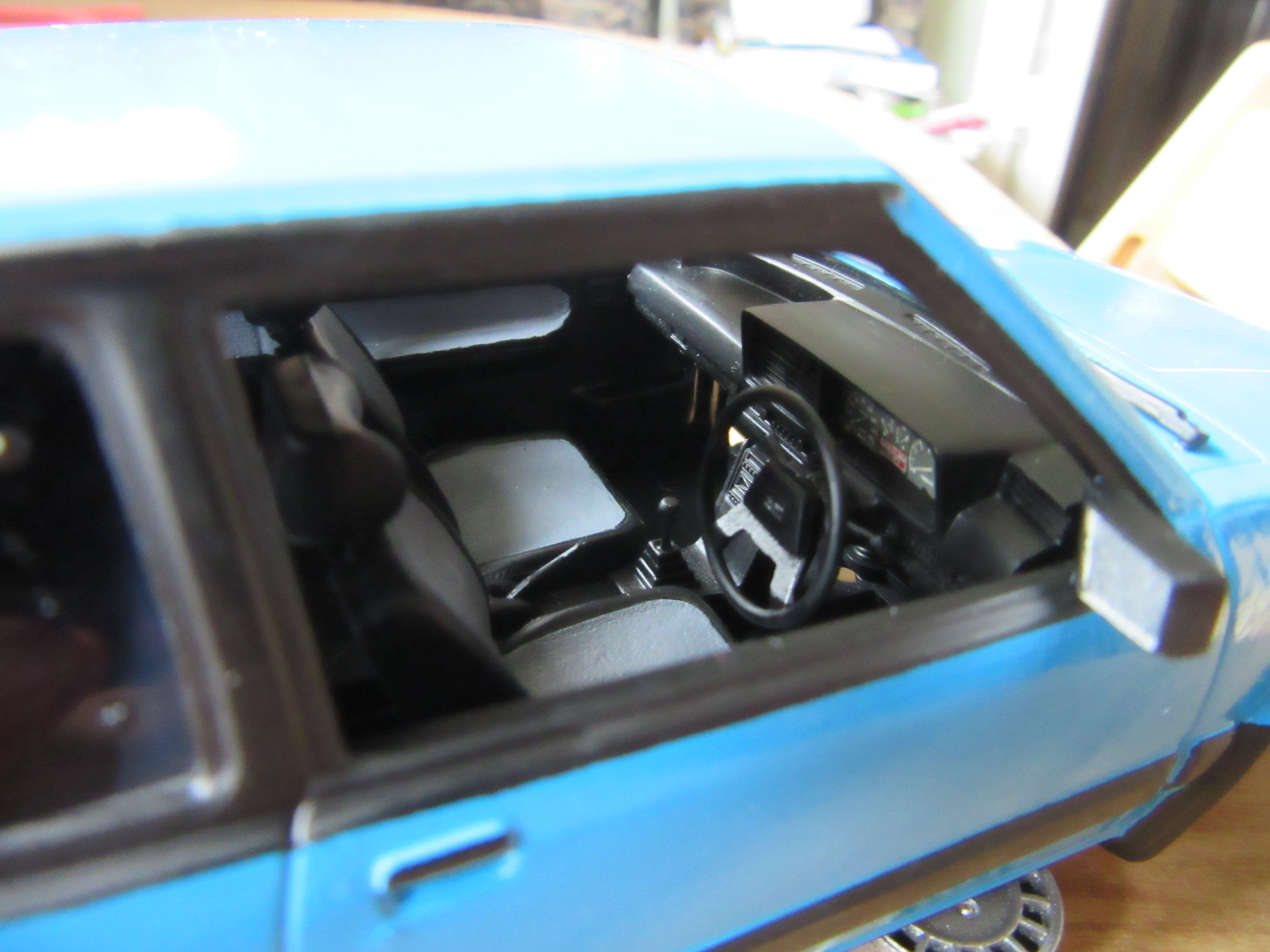
Seats done.
3 points
-
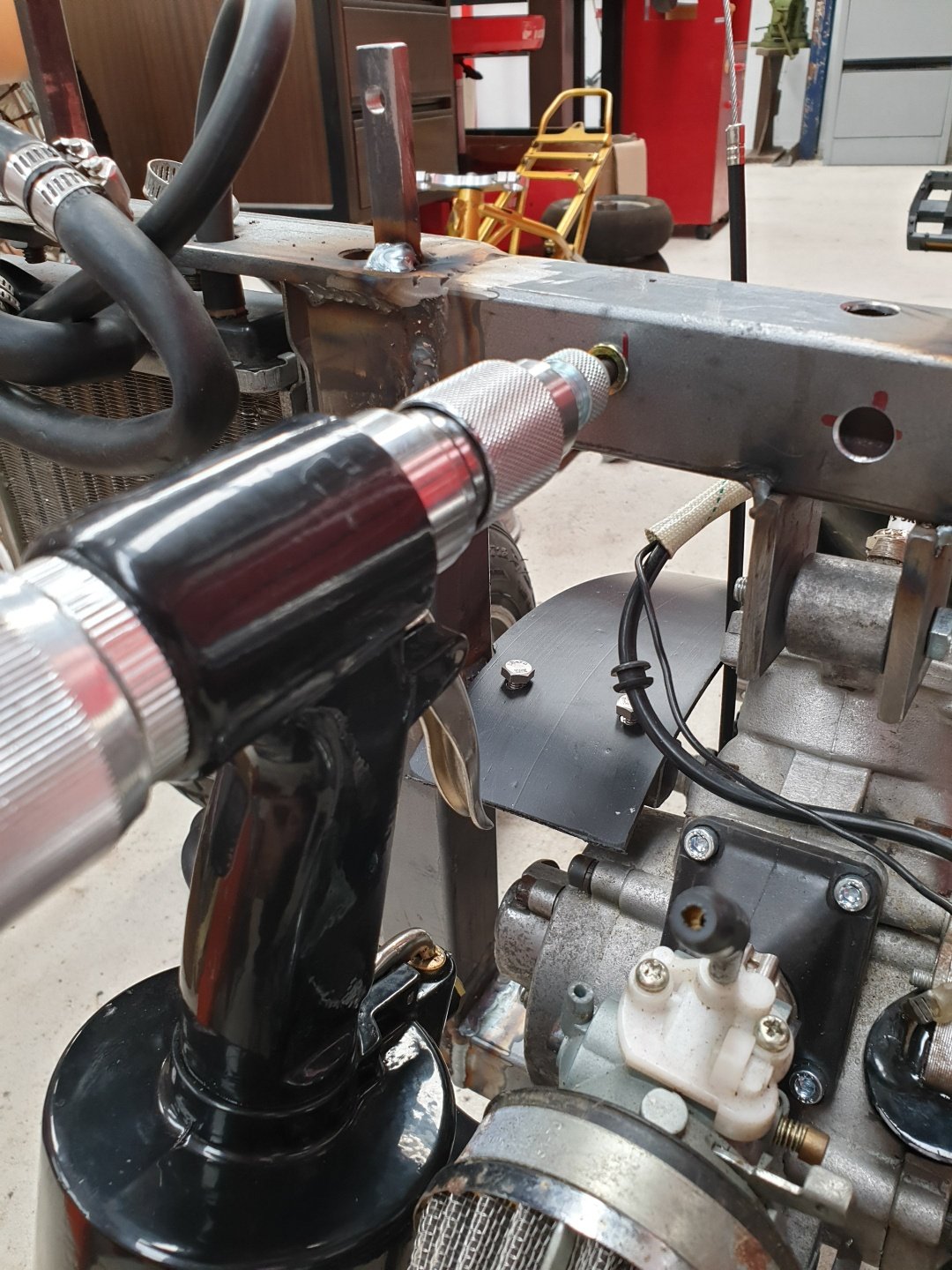
So I guess this is where we start then. The first port of call today after having the car delivered was to work out why we had no power. I popped the bonnet, and yes there was a battery. Ok, let's remove the battery and see if I can throw some charge into it. Ctek says NO. With the charger connected to the battery, nothing. No lights on the charger, and if anything, the charger started acting weird. Guess that's no bueno then. Hope my charger is OK. A quick trip to Supercheap sorted out a battery for me. There is very little space for a battery, so a bit of digging in the Century Batteries catalogue yielded the biggest battery that would fit the same footprint, an NS60LSMF Connecting this up showed that we finally had power. The dash warning lights come on with the key, the driver's electric window is working, albeit slowly, and the central locking works. Strangely the headlights did not respond to the switch, but some wiggling of the wires behind the switch sorted that out (yeah, I'll need to look into that). The next obvious step was to see what was up with the fuel tanks. Now that I had power I could see the fuel gauge was reading empty. I decided to take a risk and try dumping some of BPs finest 98 and injector cleaner into the tanks and see what happens. I split the fuel and cleaner between the two tanks as evenly as I could. Since I had been told it was possible the accumulator had failed, there is a trick to work around this and still have the car start and run normally. The accumulator works to hold fuel pressure in the lines when the engine is off, but when it fails the lines no longer have pressure, and the fuel pump only runs when the engine is turning, so it takes ages to build that pressure back up. The trick to work around this is to have the pump run when the key is turned to ON so it primes the lines. The simplest way on early cars like mine is to disconnect one connector from the side of the fuel distribution unit. This causes the pump to run when the key is on. Easy. Its the blue connector in the top photo, and the green plug goes onto it (strangely... why arent they matched colours?) I connected the battery and turned the key. Sure enough, I heard the familiar whine of a pump turning, and then the woosh of fuel heading down the lines into the fuel distributor. Now it was the moment of truth. I turned the key, and the engine turned smoothly over. It spluttered a couple of times, but wouldn't start. What a tease. Eventually, this happened. It was rough, but running, and even idling. I ran it for a while, and everything looked good. No obvious signs of leaks, but blimey does it make a noise! The longer I ran it, the smoother it was getting I checked and it seems to have gears, and a clutch, so that's a big win. It still hesitates a bit, but that's to be expected for an engine that has been sitting around. I'll take the plugs out and give them a clean (or replace), and check the cap and rotor condition. If everything looks OK, it may even be time for a quick run around the block. One must wonder though; if I can get it running with little effort, why couldn't the "specialist" have it running for the truck? Oh well, best not to dwell on it I guess.3 points
-
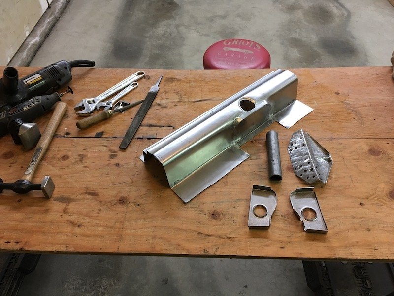
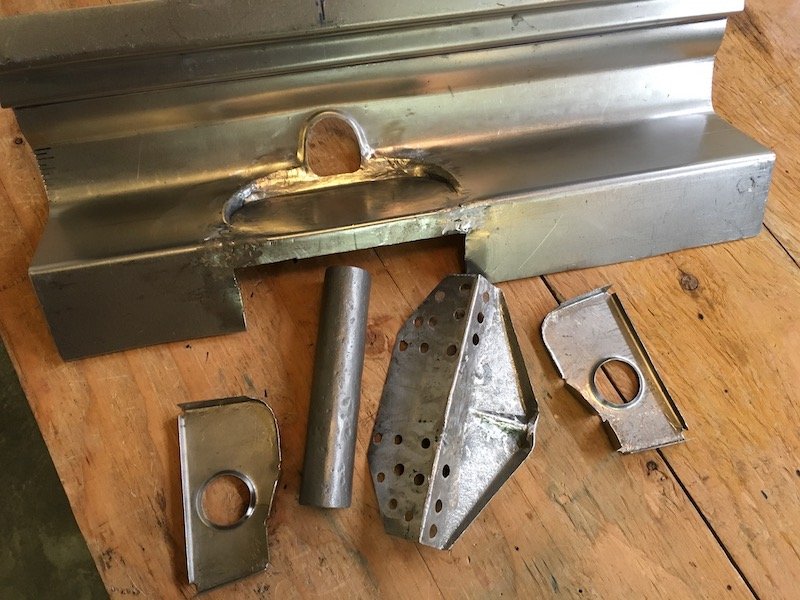
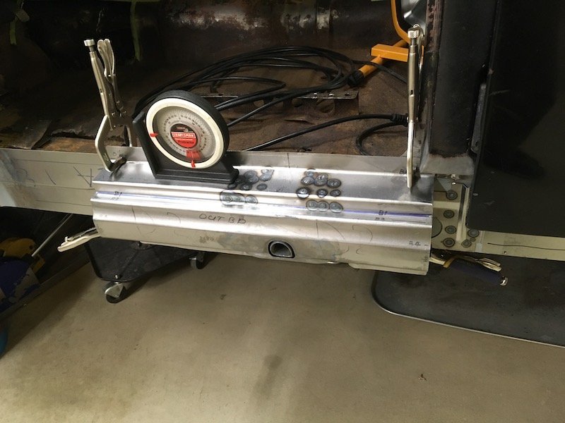
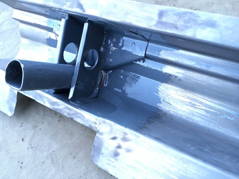
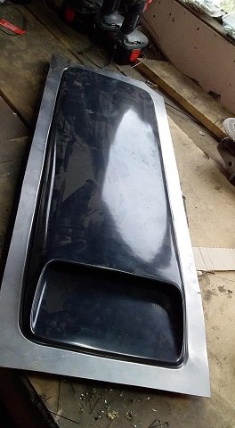
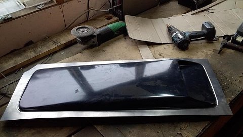
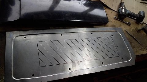
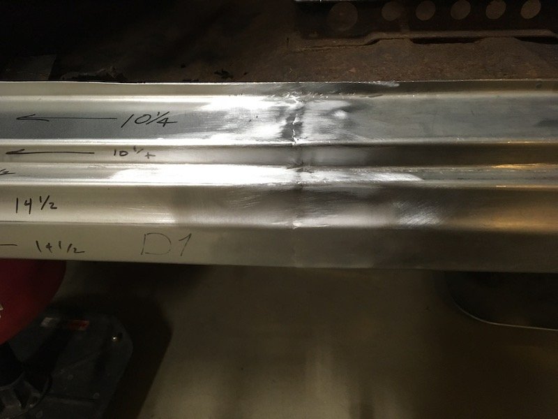
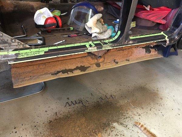
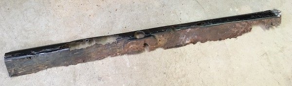
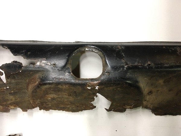
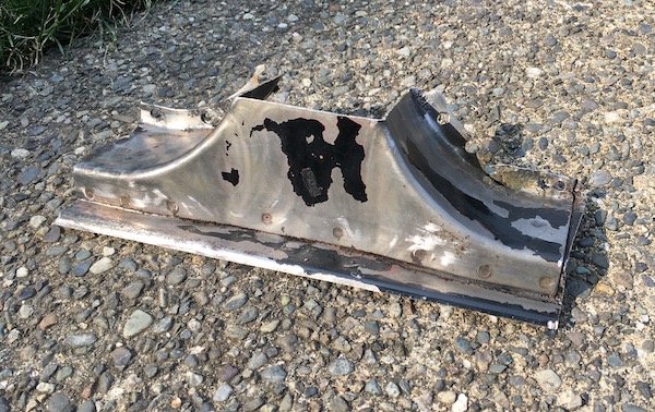
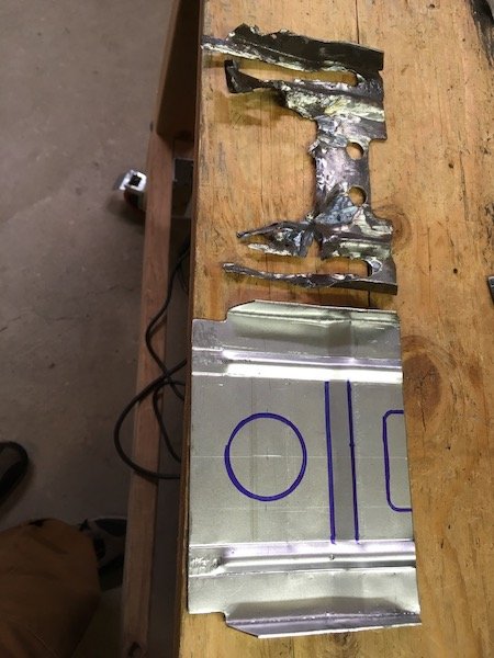
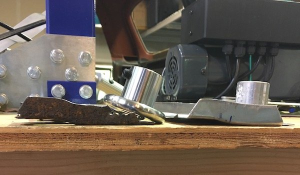
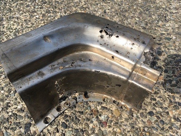
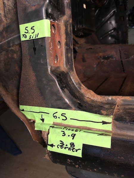
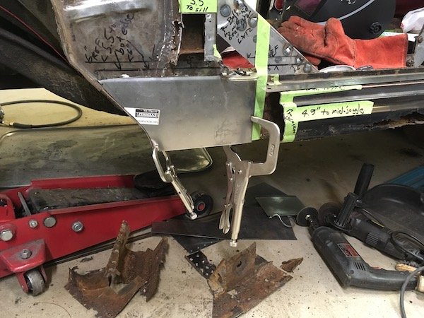
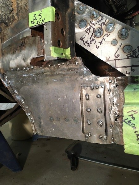
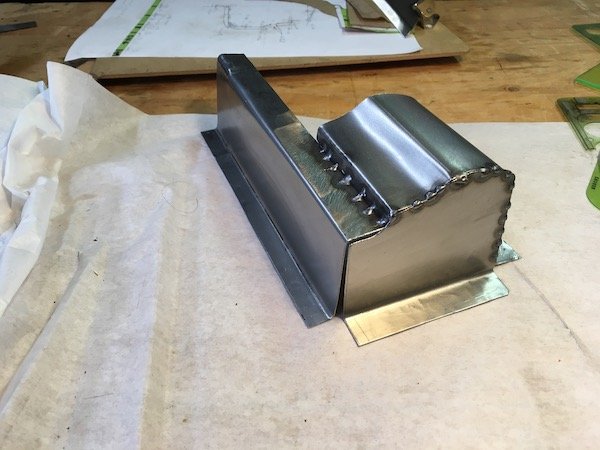
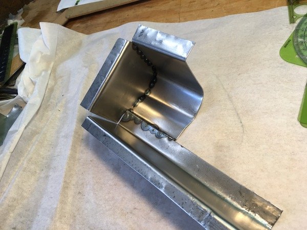
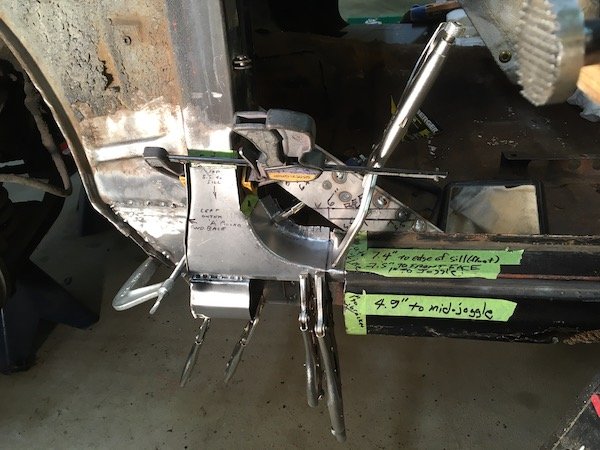
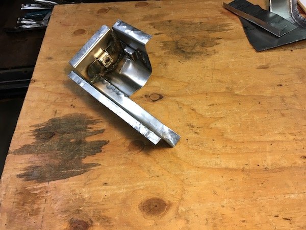
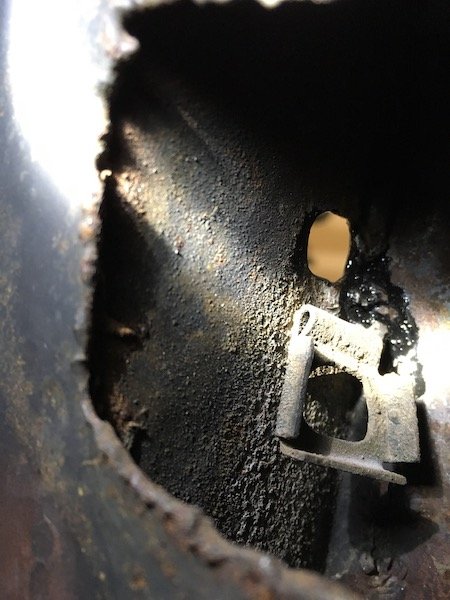
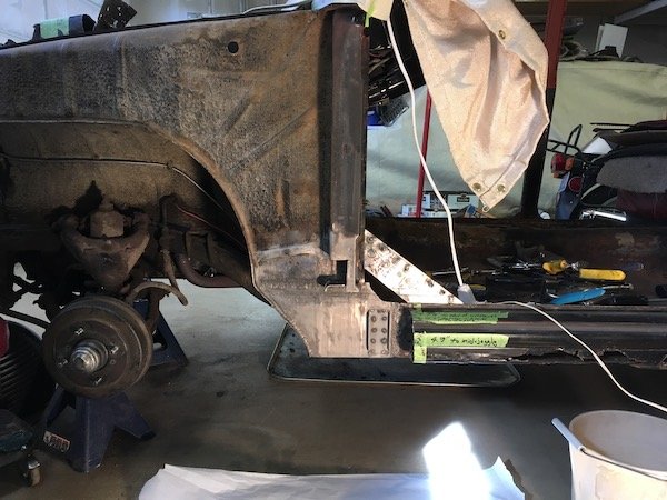
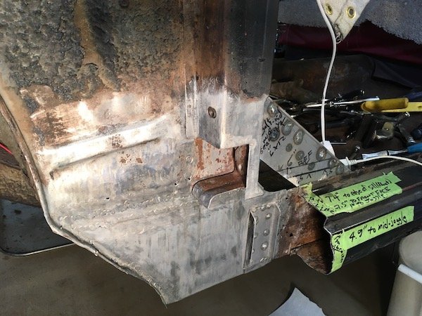
Build of the lifting jack structure Original outer sill panel where the lifting jack pipe was Inside the sill are the remnants of the jack bits Made a forming die to recreate the indented outer shape, test looked good on scrap piece so went ahead Simple as sandwich the panel and tighten the bolt Looks not too bad! Closer examination. The extra metal around the bolt hole gets trimmed out to match original. The lower pop out section (to left) is welded on and then cut off. Wrong position darn it ;( Straight on view after trimming Moving on to recreate the inner vertical stiffening brackets. Takes a bit of imagination since only about half of the originals remained Bits getting ready for weld Checking bits out for fit Sand blasted the original pipe free of rust Now really ready for weld Welded and checking results for fit against inner sill Coated with POR 15 for future rust protection. Turns out this coating can catch fire real easy and sustain flames. Next are the three outer sill segments to be welded together. I've kept a lot of extra flange widths, top and bottom, to resist warping. These flanges gets trimmed back to about 1/2 inch. Discussion: https://oldschool.co.nz/index.php?/topic/60267-marts-pl310-61-datsun-bluebird-sedan/
3 points
-
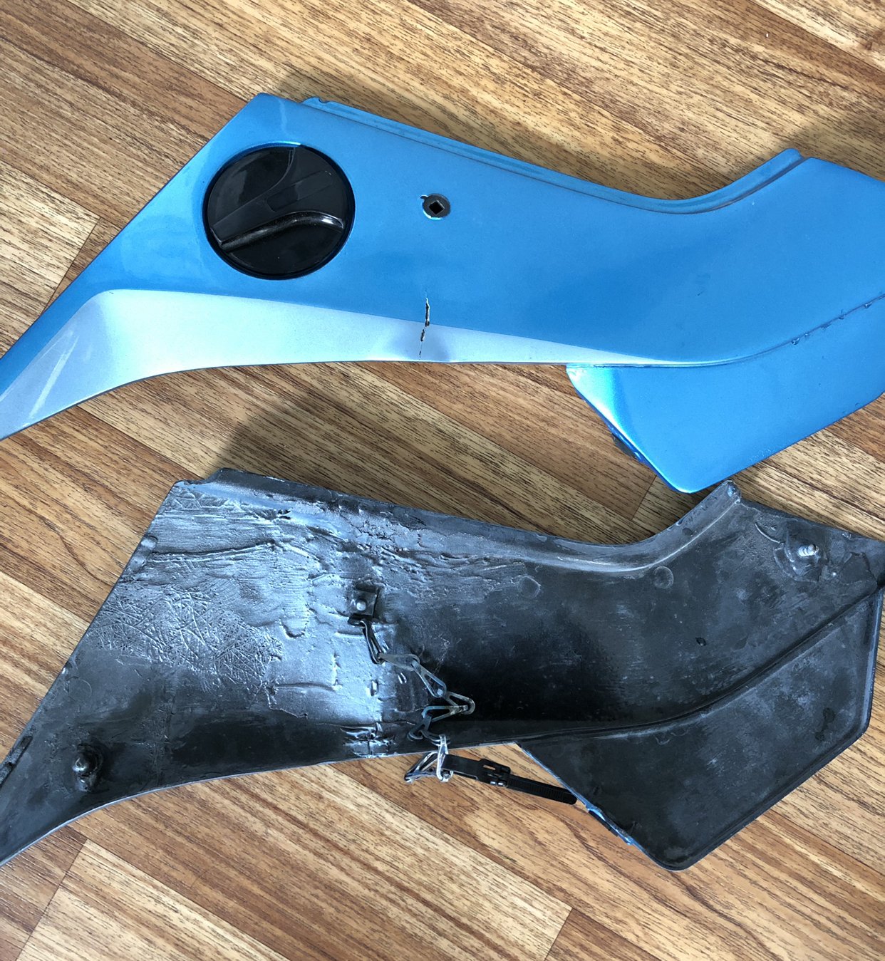
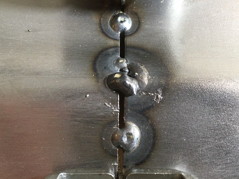
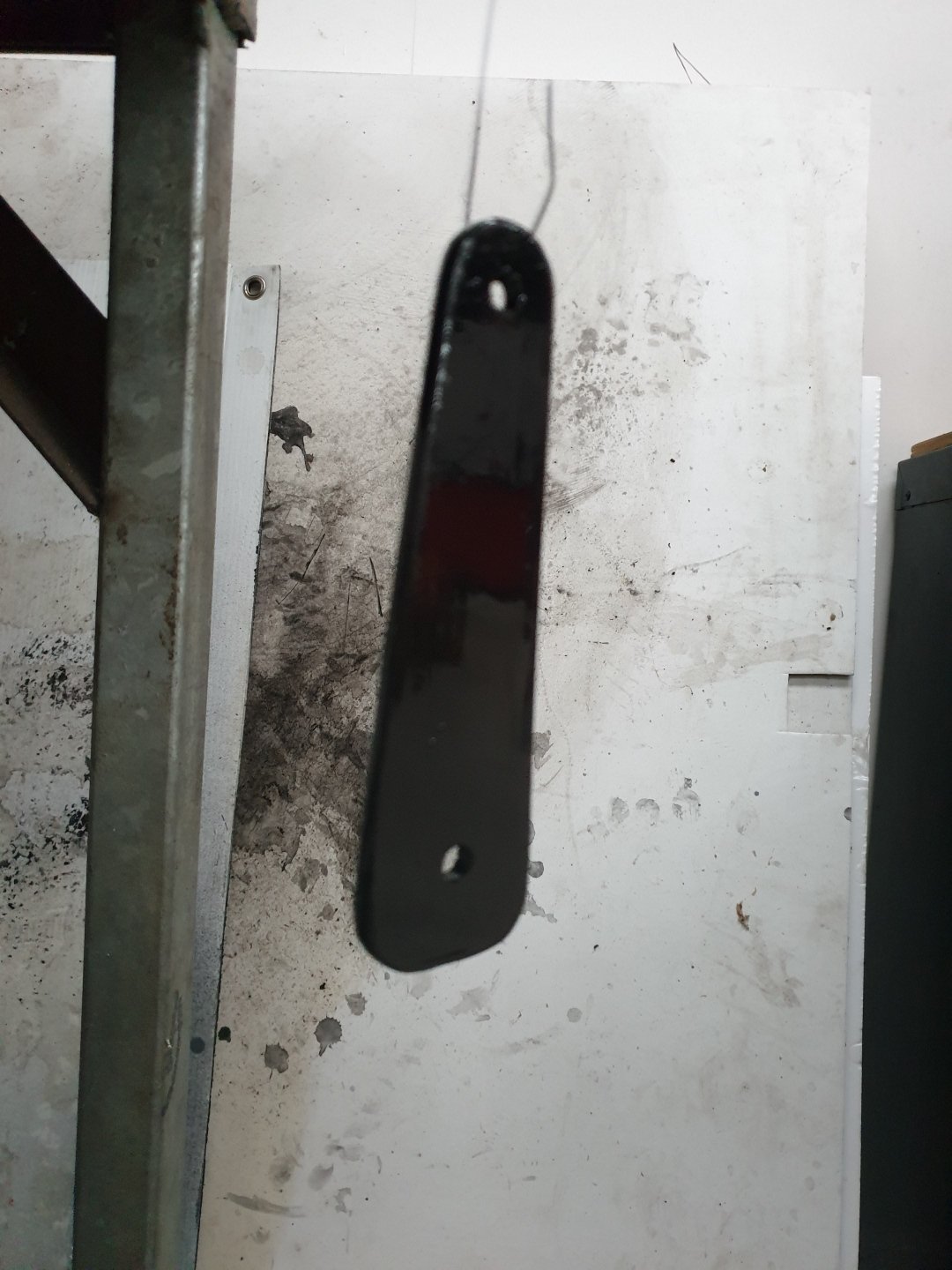
The PO also created the fairing security stay which consists of bolts through fairing copper tabs and plug chain and a re usable cable tie to attach to frame. Oh and bog.
2 points
-
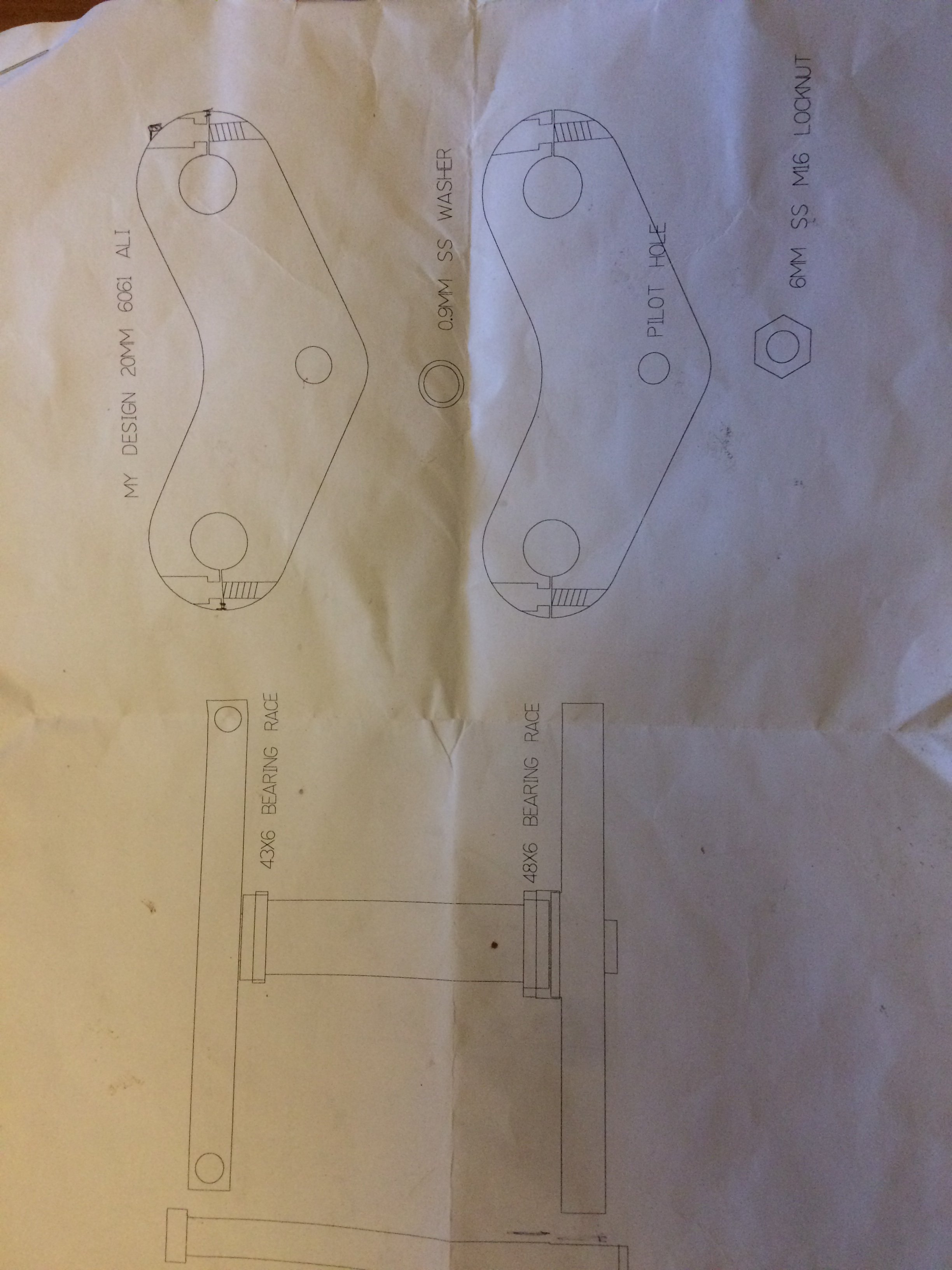
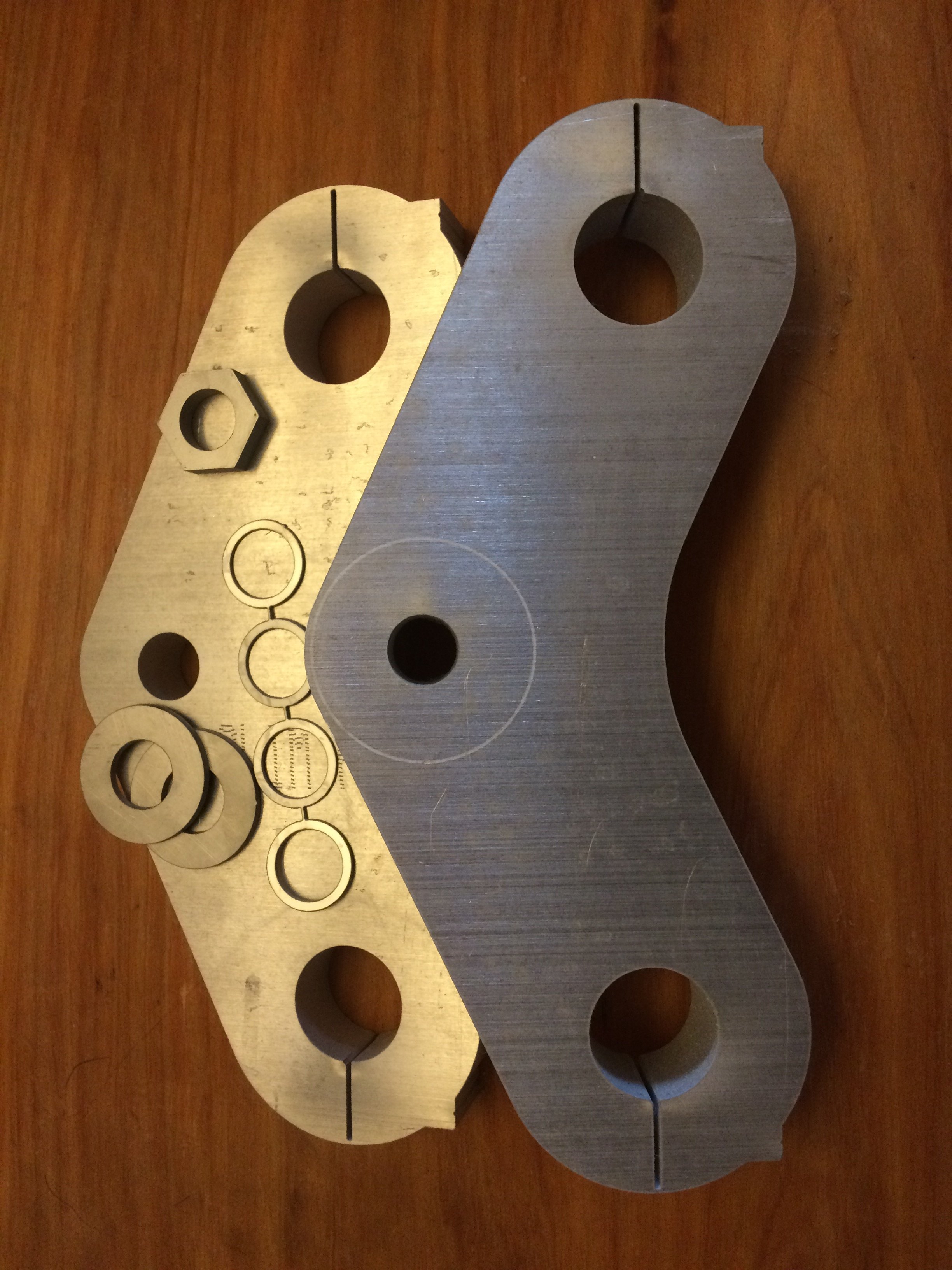
Warning, gratuitous CNC usage in the following updates, readers may feel extreme jealousy/envy I have access to a waterjet at work. Triple trees sorted.
2 points
-
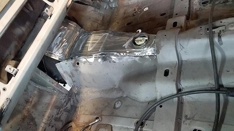
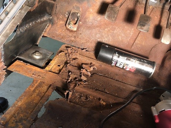
Also started on the floor this is the worst of the rust on thepassenger side drivers side is good. it was cold as all fuck today so this was the best place for a coffee break2 points
-
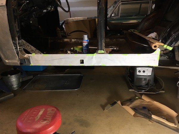
Sunday evening update time. Fuck the weeks go past fast, I must be getting old. I made some hatches for the rear openings; I added some covers for the drawers so my tools don't fall out; I have yet to find a really good lock system for those big drawers yet... I then made a bracket to hold a power steering reservoir in a place where it was easy to access; I made some radiator supports; After I made these I found the Dyna rad supports in my box of shite, so now that I have adjusted these into the correct position with the cab on I will probably change these over. The Dyna ones have some isolation built in which is a good thing. The rad itself is sitting on two M8 isolation mounts on the underside, connected to that bit of angle. I will cut the angle into two smaller brackets, that shit was just to get them in the right spot during the setup. All snugly in place. The reservoir cap does hit the cover so something will need a cut and shut. I then stood back and admired the goodness; O fuck yes.2 points
-
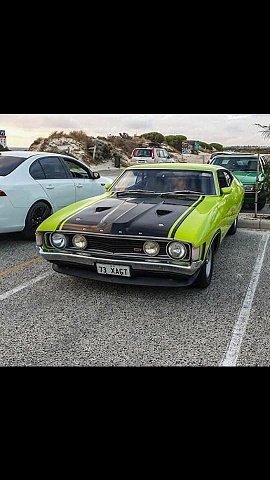
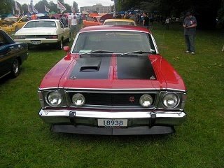
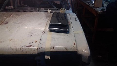
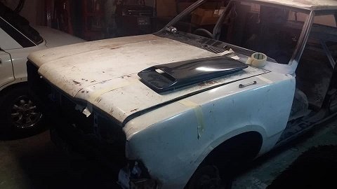
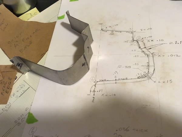
so now the motor and box are back in i can make a start on a couple of things one being the tunnel...just need to put the clutch fork and slave cylinder in on the passenger side and the starter and clutch pedal on the drivers side and i can finish it off.. and the cold air feed/air box...i want a sealed box feed air from the outside but when you one the bonnet you can see the ITBs (other wise whats the point ay lol) all so regardless of the colour i paint the car i all ways planned on painting the bonnet the same as the falcon XAGT. i looked around at bonnet scoops for ages and wasn't keen on the wrx scoop on your mums honda style ...had to be long low and slim.....so went with the falcon XWGT scoop so it looks like it will fit the plan is to have the scoop on the bonnet with the filter on the otherside of the bonnet so when you open it you can see the filter and then when closed it will seal onto the box around the trumpets. now the easiest way for me to do this is to make it all out of the car then cut a section out of the bonnet and weld the whole thing in so i made a cardboard template and cut some steel out of the sheet and bead rolled around the template flip it over and it means the scoop will be recessed into it. i did some searching on the interwebs for panel filters and it turns out i might have found the perfect one......size and price. ....so i ordered a Porsche 928 k&n panel filter 517mmx157mm and around 20mm thick. and this is the room it will take up. cheers
2 points
-
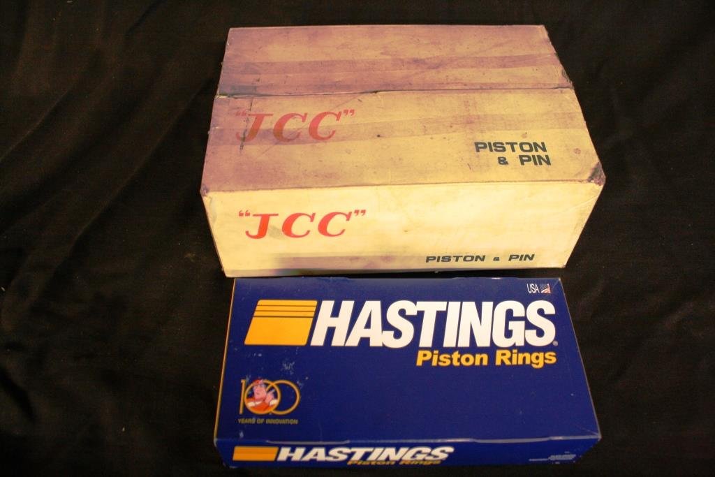
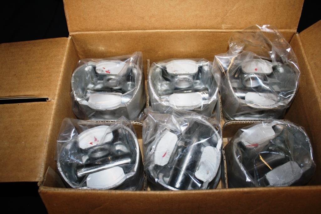
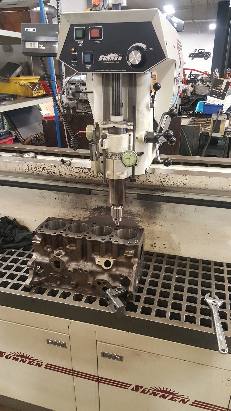
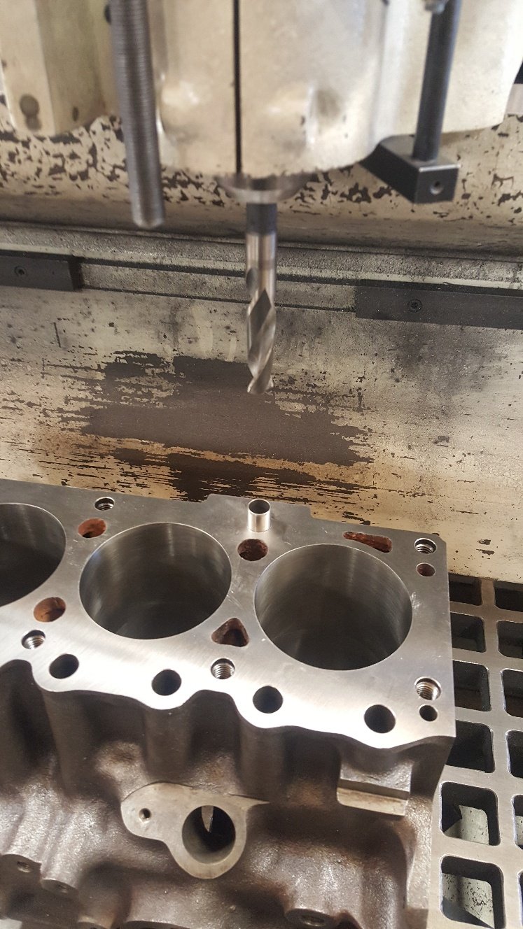
After making the call to take the block out to 60 thou oversize (hard to argue with an internal micrometer) the hunt was on for suitable pistons. Problem is these motors were designed to run on leaded 100 octane petrol (yes real lead, the stuff pre-millennial ‘real jokers’ used to have in their pencils!) and the best we can buy in our modern times is BP98. To add another problem both the head and block had probably been decked a number of times and I was now planning on pushing 208 CI displacement into a 186 head. With flat top pistons off the menu I managed to track down a set of ‘new old stock’ .060” over JCC dished pistons in Australia complete with pins and chrome moly rings. You have to love the 30 plus year old tea cup stain on the end of the box, if they could talk I'm sure these ‘new old’ spares could tell some stories.
2 points
-
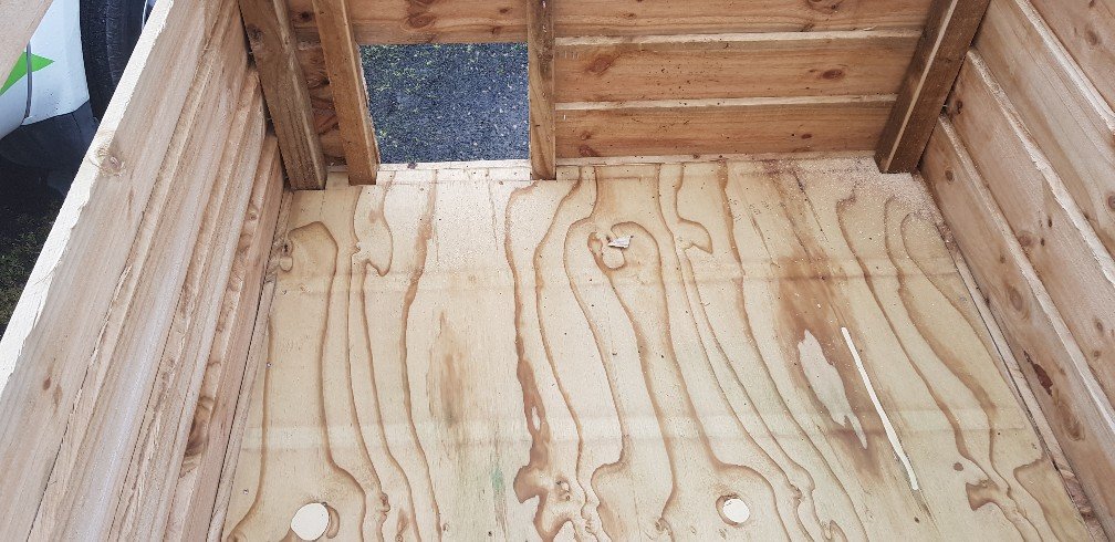
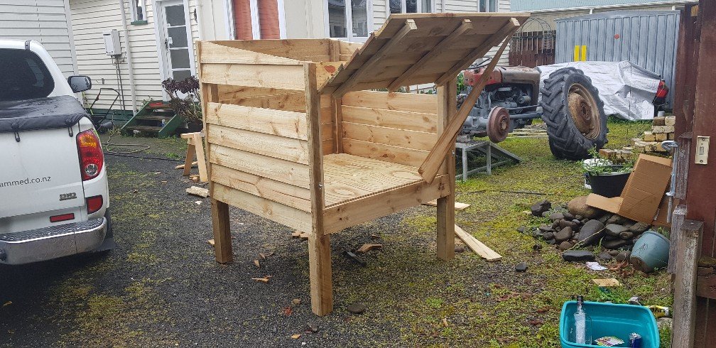
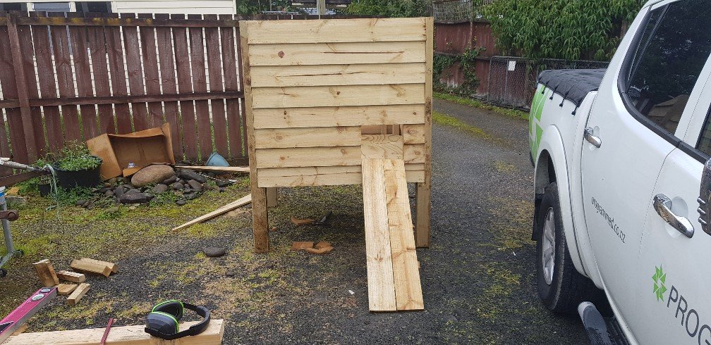
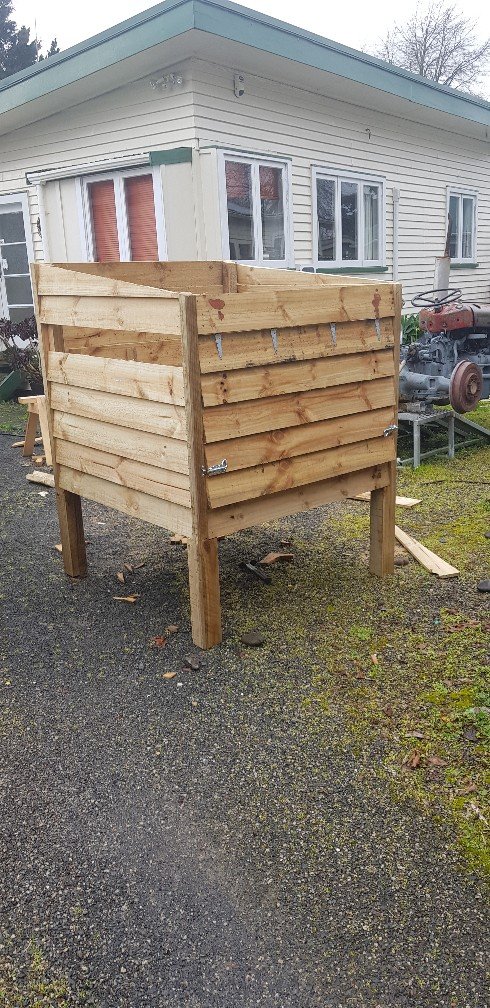
Is that your video? You spelt extended wrong I been building this. Started last weekend in between rain showers Needs roof and nesting boxes then dry weather for paint ( or stain)
2 points
-
Some wiggling of wires behind the light switch (yeah, ill need to look further into that) and this happened. Thankfully headlight motors work perfectly.2 points
-
finished modifying the crossmember and put it back in the car. everything's done now, fluid lines hooked up, kick down connected, shifter connected and spedo cable hooked in. just need my drive shaft back (should be Tuesday) then its test drive time. cant hook up the converter lock until i figure out how the fluid pressure circuit works which ill know when i drive it. 2019-08-10_12-08-21 by sheepers, on Flickr 2019-08-10_12-08-29 by sheepers, on Flickr2 points
-
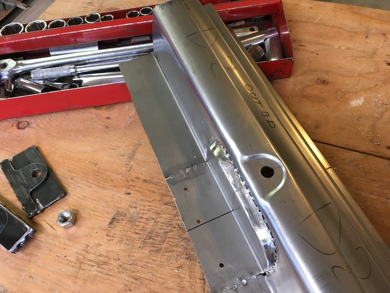
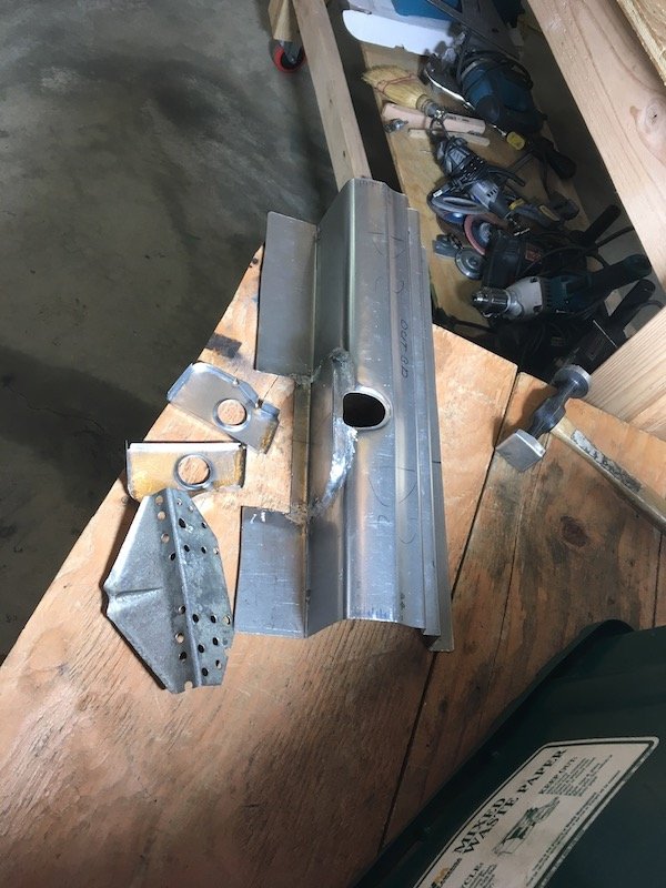
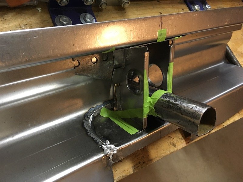
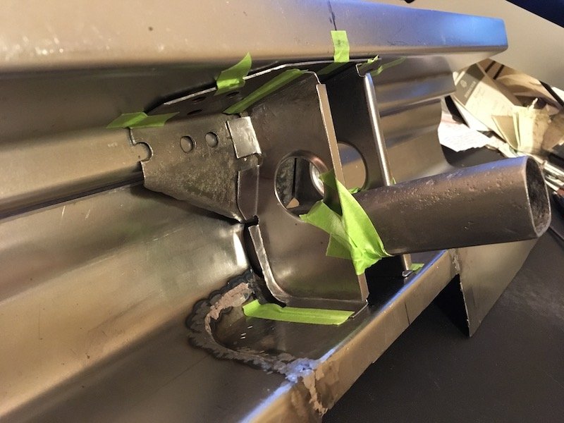
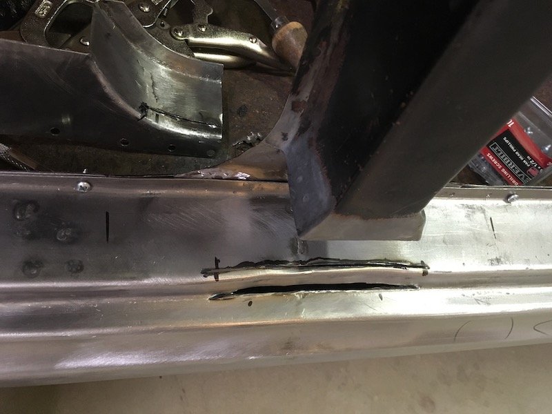
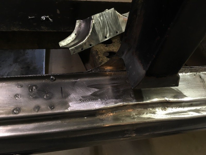
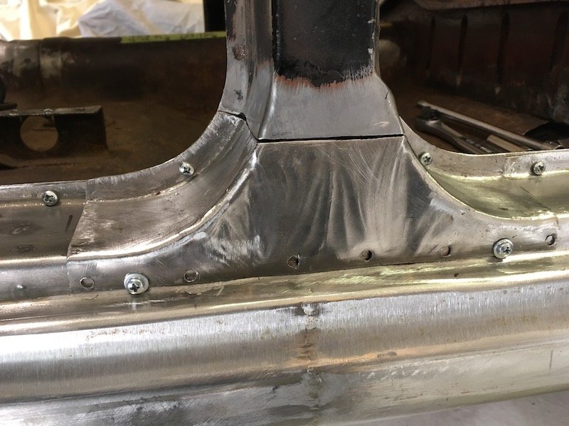
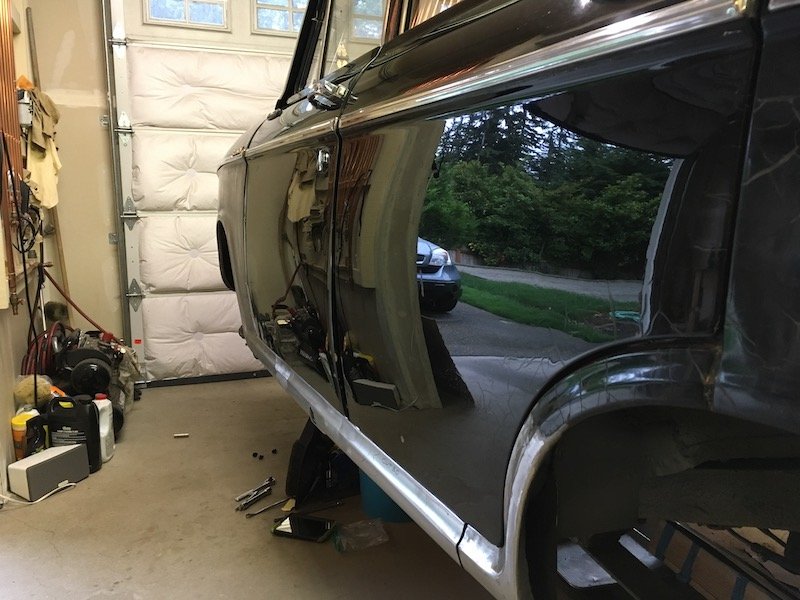
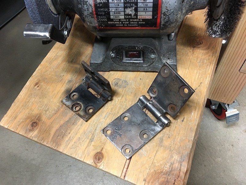
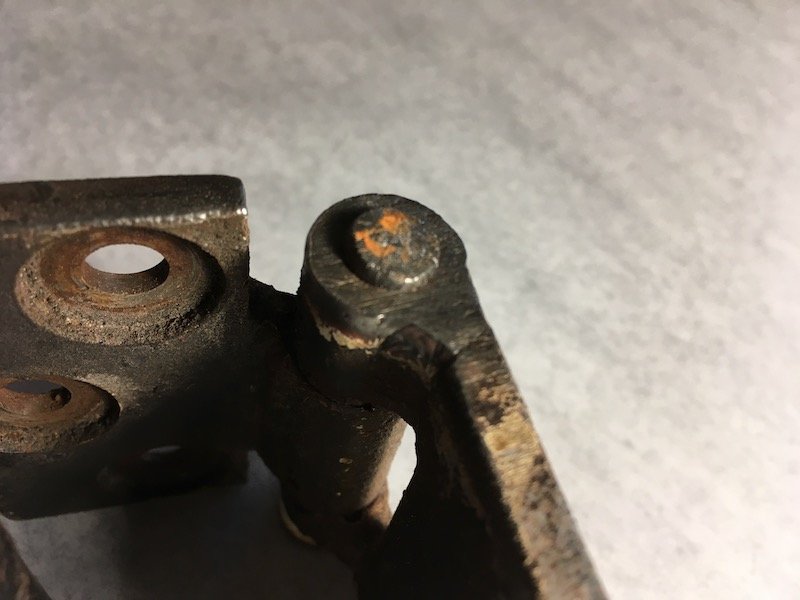
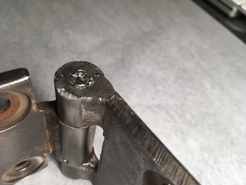
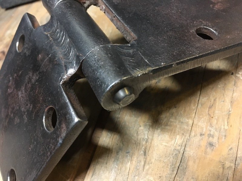
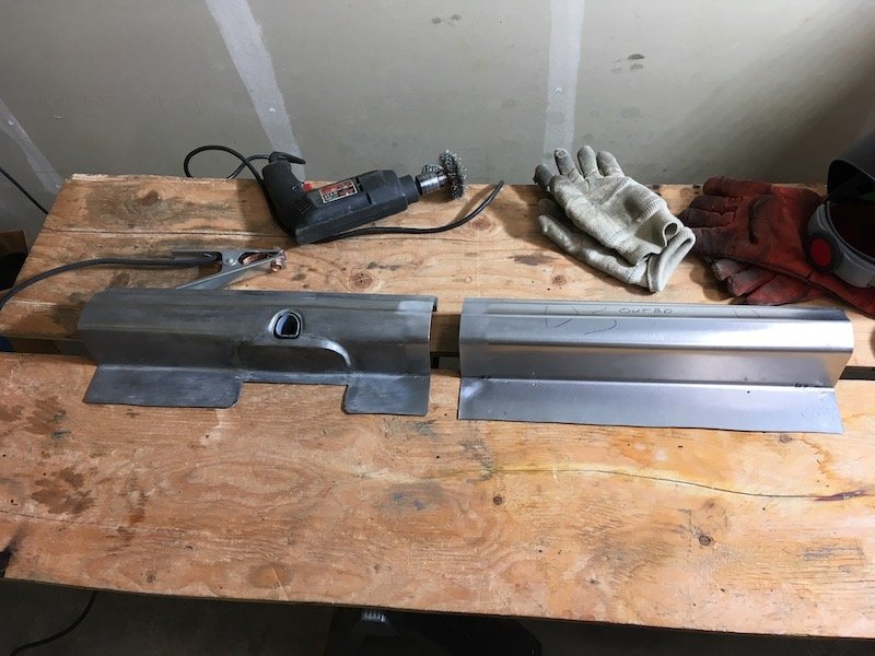
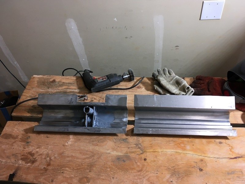
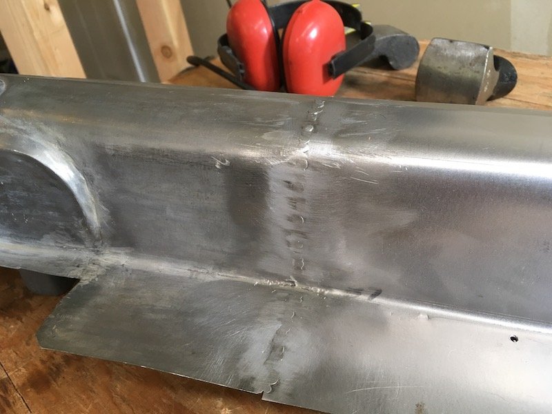
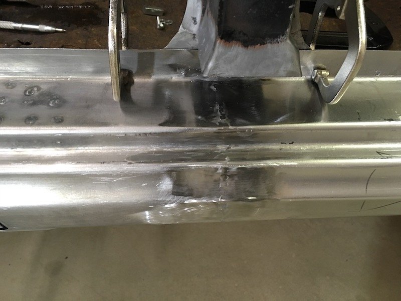
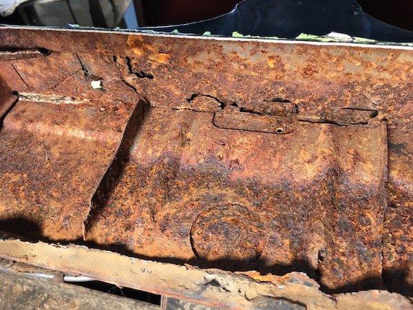
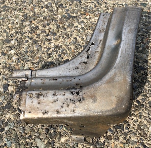
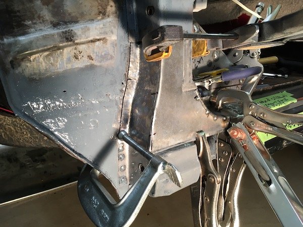
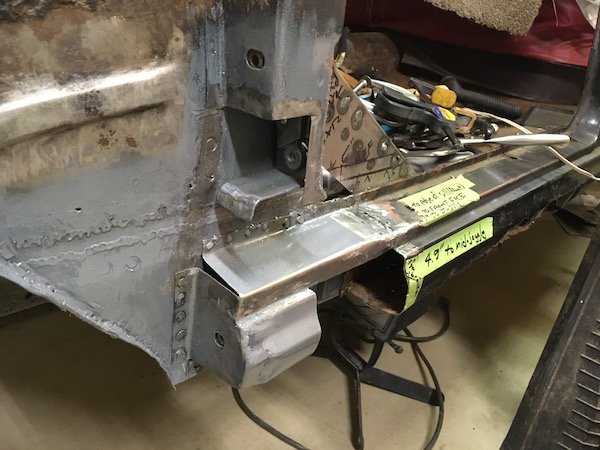
Catching up with progress today. Beware of this, my favorite tool over the last 26 years, the good old knotted wire wheel and angle grinder. Very handy but dangerous. Took a nip out of my flesh the other day. Ripped right through the glove. I should reinstall the guard of course. So I went to work by finessing the fit of the forward end on the outer sill by forming a lip on the end, making pie cuts and welding up the gaps. The objective to set it up for a flush contact with the A-pillar stub. Btw, the outer sill assembly will not be welded to the body until the floor is fabricated and installed so I can get a coat of epoxy primer over the resulting welds on the inside of the sill box. I've got it fastened with screws temporarily. Next, I had to make adjustments at the base of the B-pillar by joggling the upper surface of the sill inboard. Did this with some cuts, pushed metal in and welded shut. The top flange of the sill was originally joggled as shown in these left and right B-pillar base pics. Next I adjusted the C-pillar or dogleg. The bottom of which was tucked in way too far inboard. This resulted in an unacceptable mismatch with the outer sill profile. So I cut a slot in the bottom plate and welded in a 1/4 inch strip. Then had some fun time buffing out and polishing the now 42 year old repaint job on the doors. Don't ask why, I just did it on impulse. The doors do need repainting but it does not show that in the pics. I wanted to rebuild the hinges to make sure thing are fitting correctly. I grabbed the hinges off the right front door to experiment with. It did not go well with my attempted pin removal methods. First I tried pressing the pins out with a hydraulic press but it just began mushrooming the pin. Same for the big hammer and drift pin technique. And yes, I was pushing on the correct (not splined) end and supported the hinge properly on the other side. It looks like the pins will have to be drilled out. I'm not going to do that with a hand drill and not without sourcing new pins and bushings first. It appears I'll have to send them in for rebuild at a shop somewhere. Before I pushed against this end of pin Fail Fail Then worked on the left front fender some more. Welded the two halves of the aft inner vertical structure together with a lap joint for a rigidity. Cleaned, acid etched and painted rust scarred and pitted areas on the inside with POR-15 gray. Polished the outer surface with 3M scuff pads on the angle grinder to help see the waves and indentations better and work it smooth with hammer, dolly, rubber hammer, etc. I'll weld the inner structure to the fender once everything is coated with epoxy primer. And finally I set about repairing a bunch of damage on the trans/driveshaft tunnel. This 310 Bluebird has had the wrong transmission swapped into it back in the early 80s. The original trans wore out the 2-3 shift fork and this spare unit was installed but would not fit. So the side of the tunnel got torched out and it was made to fit. There is a huge difference in size between the two trans. The all synchro trans is a side loader, which is not only much wider but also longer. The original 310 trans is a top loader. Anyways I had to fix the gapping hole and make it adaptable to either trans since I still have the original and it is repairable. Then I went on to replace the aft section the covers the driveshaft. Then patched the rusty area midway between the other patches. All is just tack welded for the moment. Pics below tell the rest of the story. Below pic is looking up at side loader. The original 310 top loader trans. Above pic. It was no fun trying to do those three plug welds upside down. Notice the parallel hat section reinforcement structure or beams running fore and aft, I don't think these were installed on later 312 Bluebirds? Looks like I hit my maximum upload limit here for this post, and it is a late work night. Plan to catch up on the remainder tomorrow. Discussion: https://oldschool.co.nz/index.php?/topic/60267-marts-pl310-61-datsun-bluebird-sedan/
2 points
-
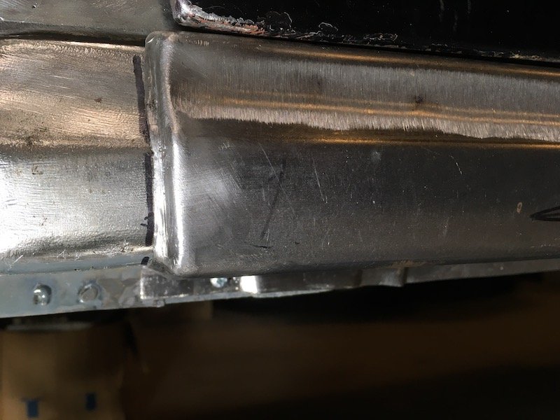
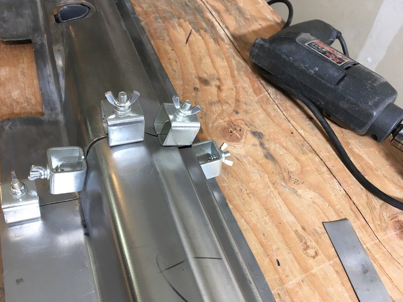
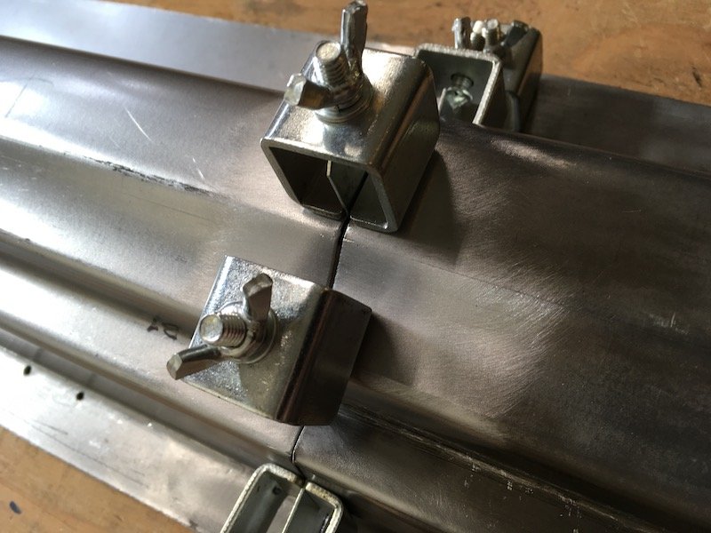
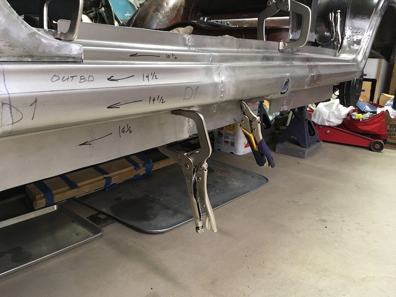
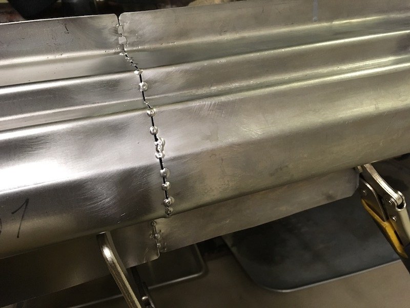
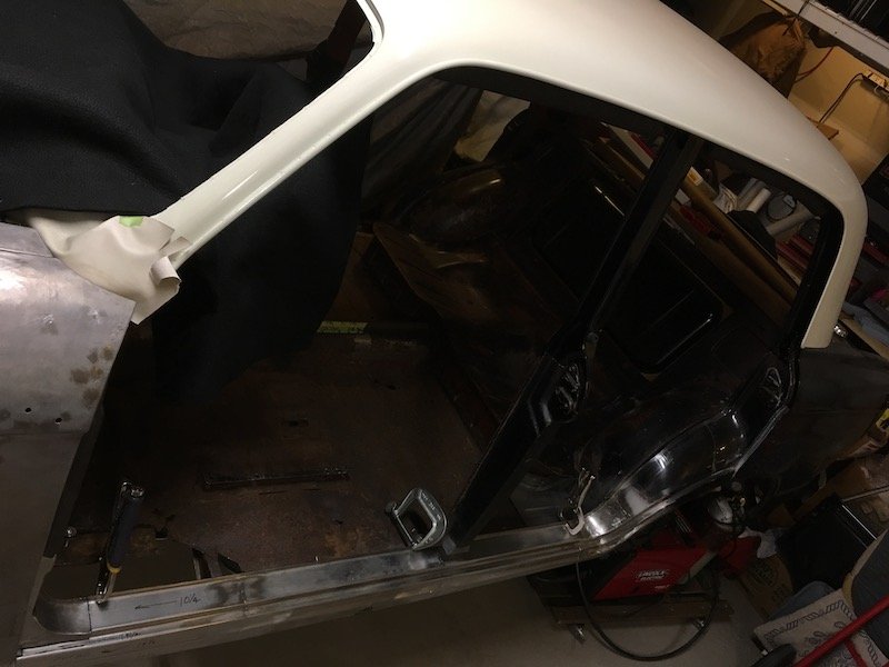
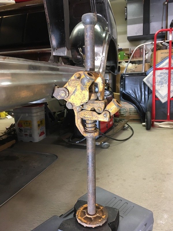
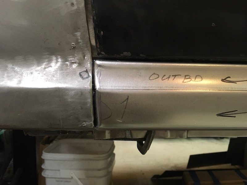
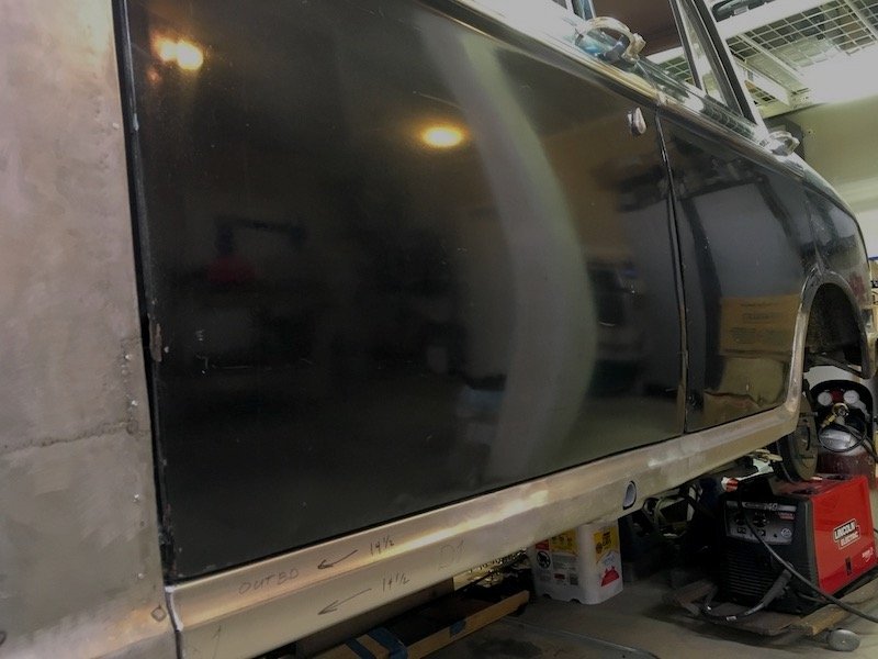
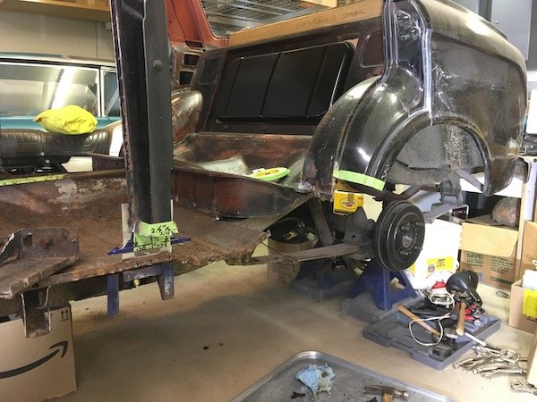
More progress with the Bluebird left side outer sill. Welded the three outer sill segments together. Started with these two shown previously Then I fixed the sill segments together with these little clamp things. These set up a nice gap to make good weld penetration to the back side. Then starting making tack welds. The first strikes in the center of pic were really bad and missed. Remainder of tack welds were usually on target. About 70 percent complete in these pics. Front and back side shown with good penetration. Front side will eventually get ground and sanded flush. Back side gets left as is. Initial grinding and sanding. After that I held the assembly against a bright light and check for pin holes, fill with weld and complete. It looked pretty good in a fit check against the car body. No weird wrapping or anything. Then on to the joining of the third sill segment to the assembly, same as the first. Except I was checking against the fit to the inner sill on the body before tacking, and after initial series of tacks, because there is a slight bow or curvature on the body fore and aft and I wanted to make sure of no issue. Did a little more rough trimming of the forward end as well so as to permit tailoring a nice fit up against the A pillar and lower stub later on. Finished weld of the last segment. Overview of the situation Then I decided to play with this. No, I did not actually try and jack the car up, just having fun with it. Later on I bolted the doors on again, probably for the fifth or sixth time, and did a final check for gap along the lower edges. Plus I formed the forward edges of the sill assembly to mate up with the A pillar stub with just the right gap next to the fender (or wing, right?) As seen underneath in above pic, there are several joggles along the lower flange to accommodate fit against several parts that are layered on the vertical inner sill plate. Below, the gaps look decent and body lines of door to sill are flush. Installed some trim to show off for the camera. Discussion: https://oldschool.co.nz/index.php?/topic/60267-marts-pl310-61-datsun-bluebird-sedan/
2 points
-
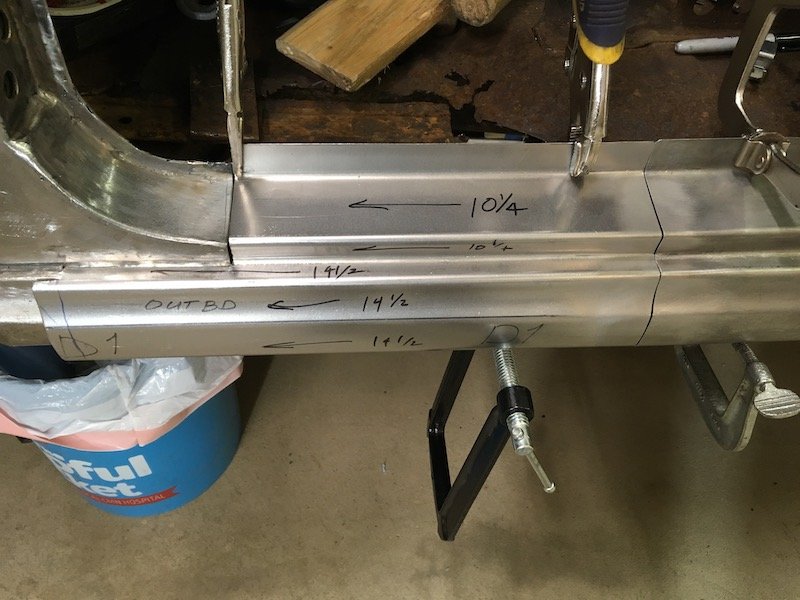
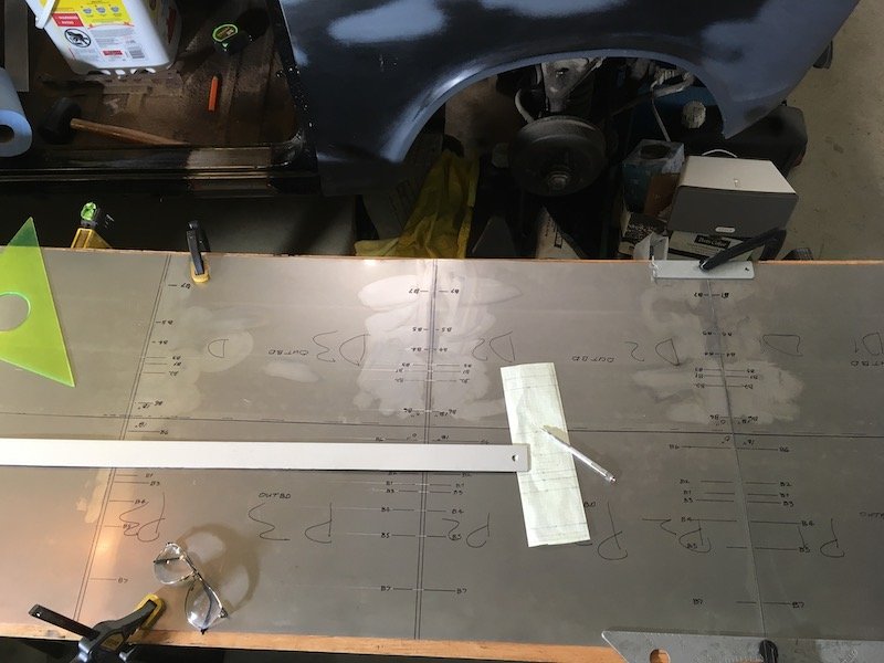
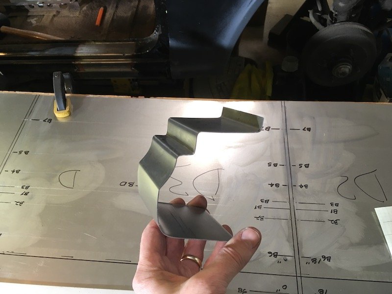
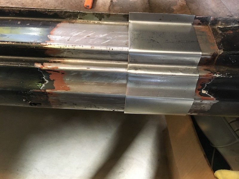
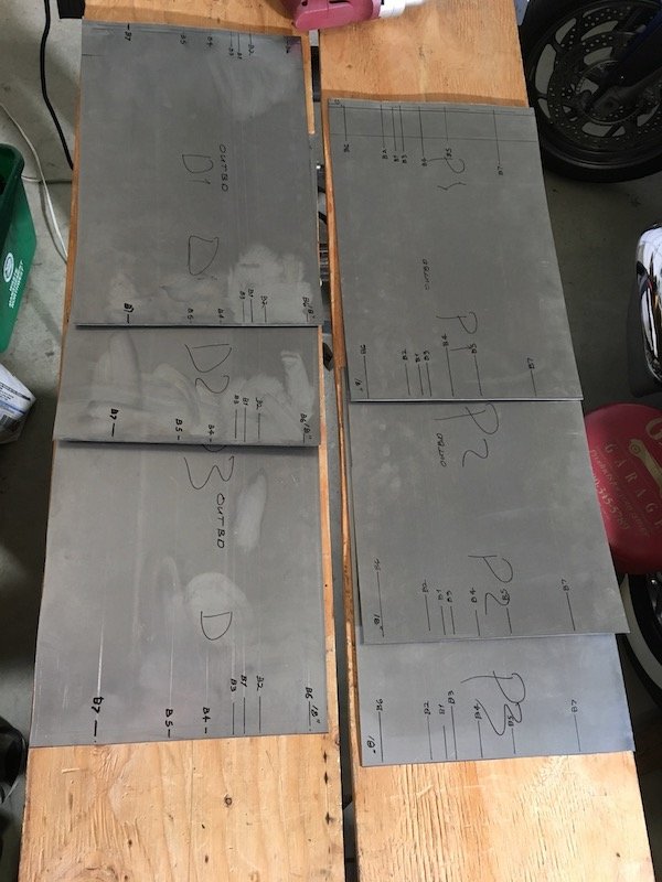
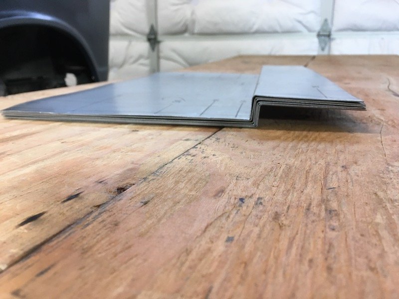
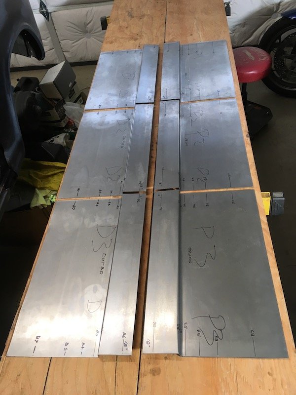
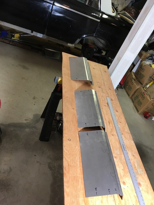
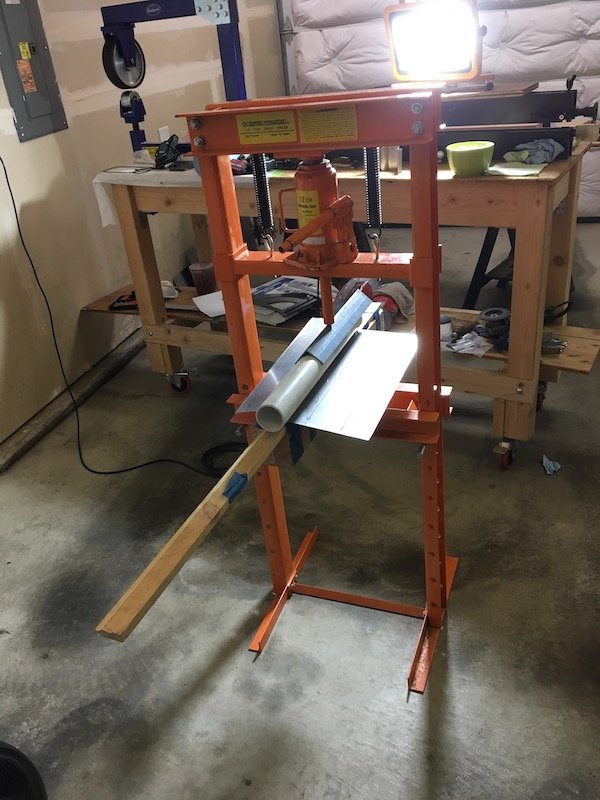
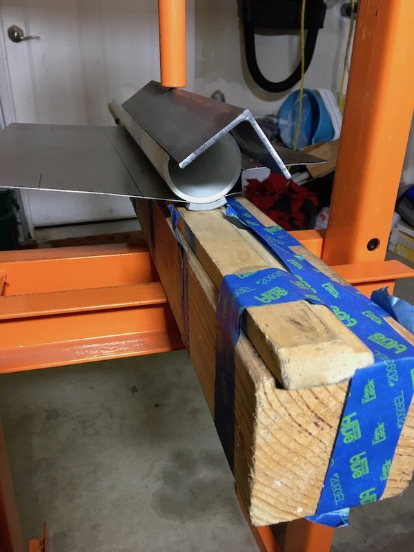
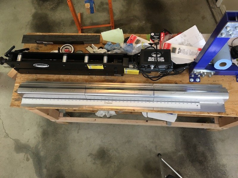
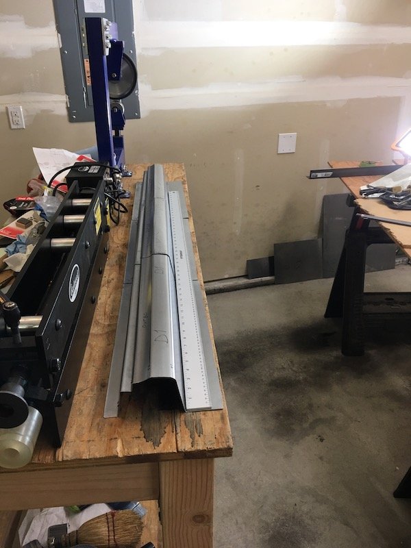
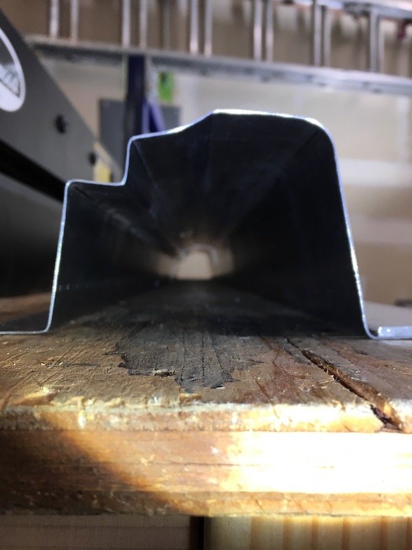
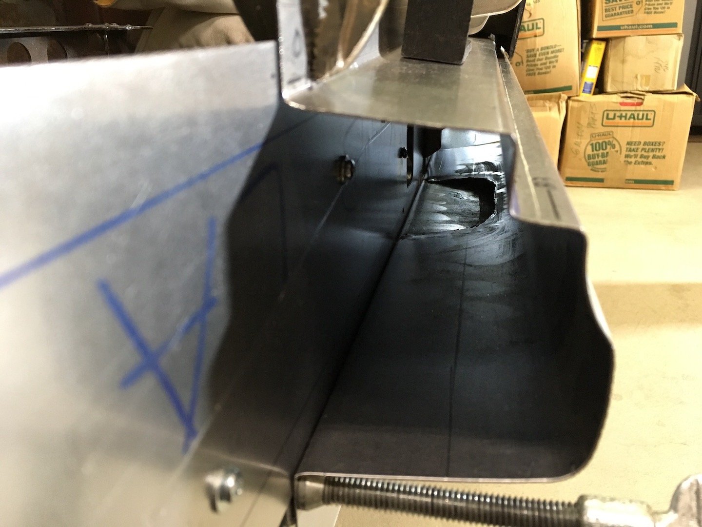
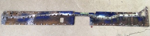
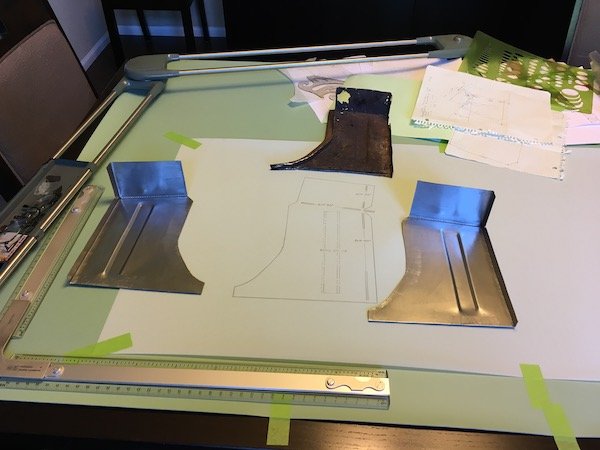
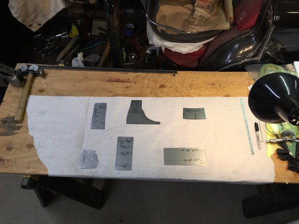
I got a little out of sequence. I should back up a little and show the making of the three outer sill segments that began about six months ago. Three segments because the metal folder tool only can do a 20 inch length maximum whereas I need about 54 inches total length. I also need to make offset bends. So there are a lot of challenges to make the sill. Makes it all the more interesting to have a go at it. Anyway, I have run into difficulties in duplicating the exact profile but it's good enough for usable parts on the left side. Maybe the technique can be improved upon for the right side. On the righthand side of the car I carefully measured and made a card template of the least rust damaged profile. Then began experimenting with and adjusting the seven bend line locations to figure out a way to make a sill. This is unlike a usual and simple sill that just wraps under the door more or less. The Bluebird has several visible body lines and a concave shape in-between. Plus there is the side of sill penetration for the jack lifting structure shown previously. This Bluebird outer sill is made of 20g sheet. Layout of bend lines The prototype profile Fits like a glove on sanitized right hand side Cut out six 18 inch long panels of 20g for left and right (D for driver's side or left, P for passenger side or right). Bend lines are marked more sharply by scribe marks so I can get good alignment when it comes to joining the segments together. B1 and B3 bends are offset bends and very close. This proves to be a problem Made the offset 3/4 inch bends for all panels (B1 and B2). Not perfectly uniform but close enough So far so good! As mentioned above, now I start having a problem at bend 3. This needed to be a tight offset bend from B1 at just over 1/2 width. The folder will only do 5/8 minimum (yet it was advertised as capable of 1/2 inch offset). Not good. I have to start compensating by moving the other bend lines to keep the visible body lines on target. The plan is to adjust the pillar bottoms to fit the adjusted sill profile, at least on the left side. I'd like a better plan for right side to get the true profile so I can leave the pillars unaltered. I'm considering having the folder plate milled down to get a true 1/2 inch offset bend, but that still leaves me with three separate segments to weld together. Either that or start over and make the whole thing as one hand formed piece by hammer forming each bend over a solid 90 degree edge of some sort. That might be wishful thinking. My crude setup for making the concave curvature between bends 3 and 4 Sandwich the sheet between plastic pipe, angle iron and squash it Checked out the fit of a couple of segments relative to the doors and the lower edge. Checked out as good. Three completed sill left side segments lined up on the rollaway workbench. Decent alignment of three segments. Looks like I can make it work when it comes time to join them End profile view of three outer sill segments all in line, just for kicks Discussion: https://oldschool.co.nz/index.php?/topic/60267-marts-pl310-61-datsun-bluebird-sedan/
2 points
-
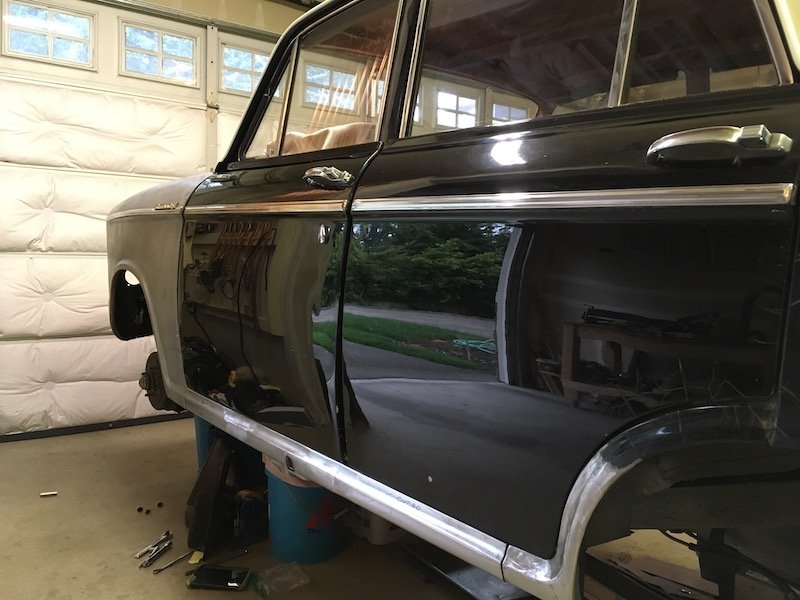
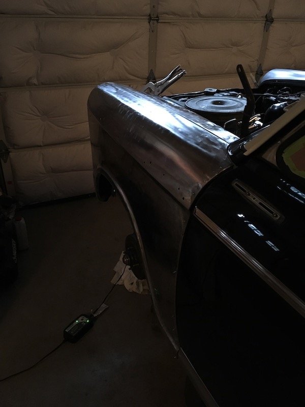
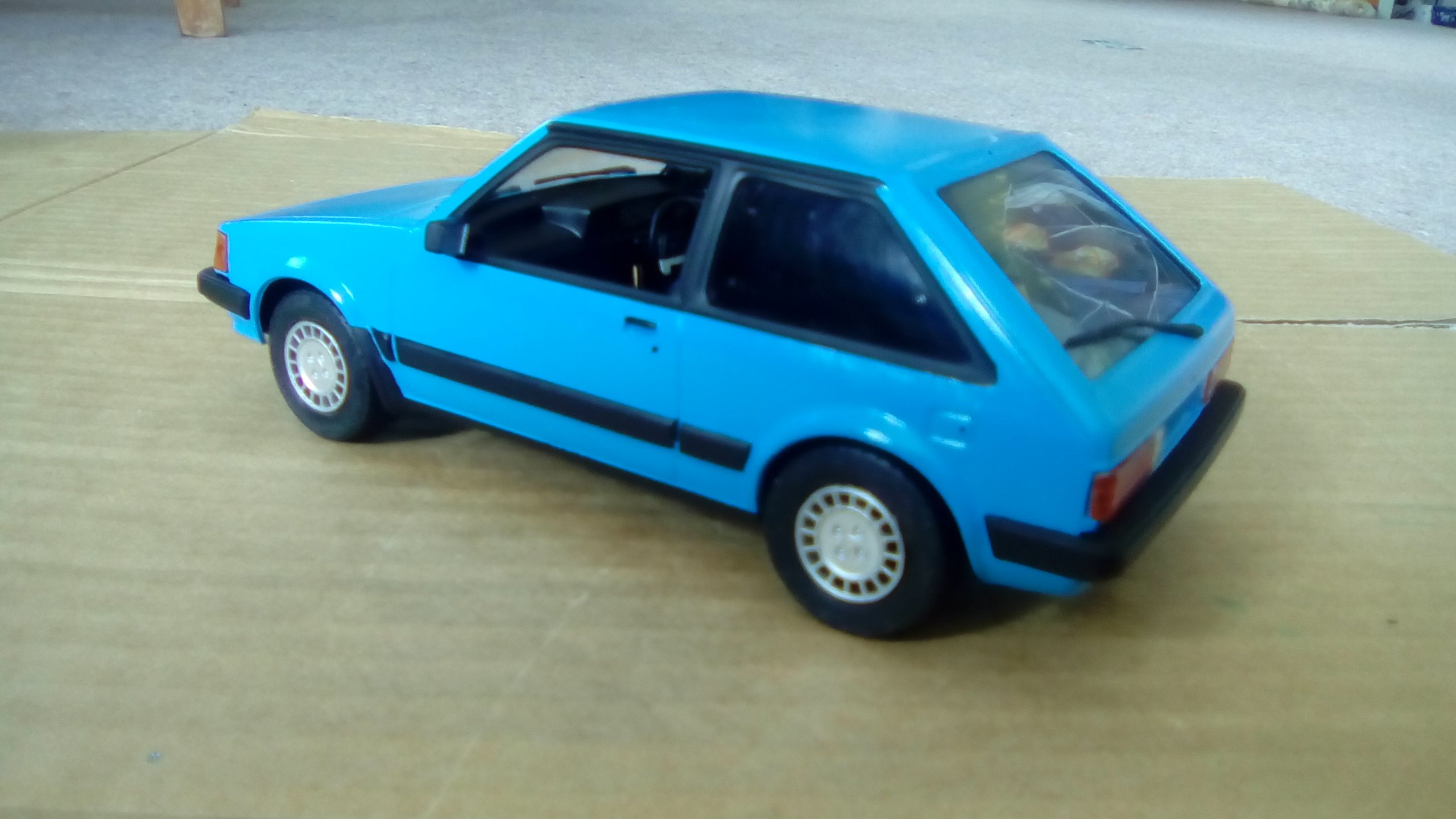
I've been ticking away at the small jobs left on this car. Badges: New Door seals all round: Mint back seat (back piece). Would love to find a mint cream one or at least a black bum piece Got it out for a clean in the sun, paint is looking great! Ignore Long champs on rear, they don't suit the car and I only had them on there so I could take it for a drive Will crack into the bonnet next weekend and get it fixed properly! hopefully.... Discussion:2 points
-
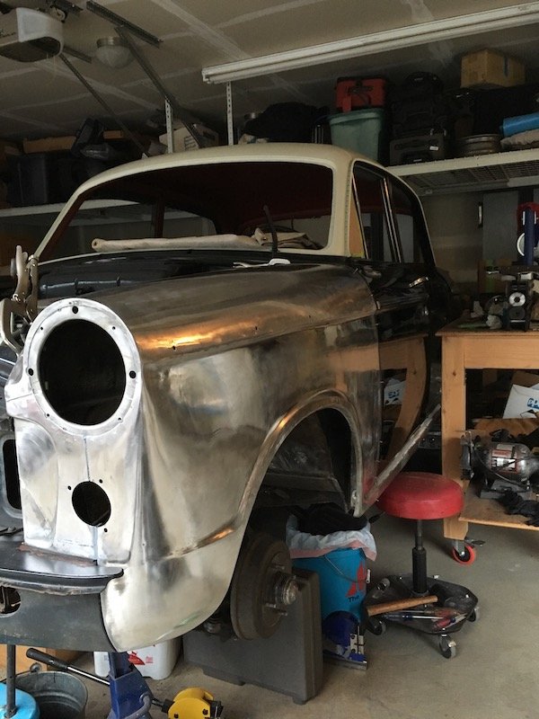
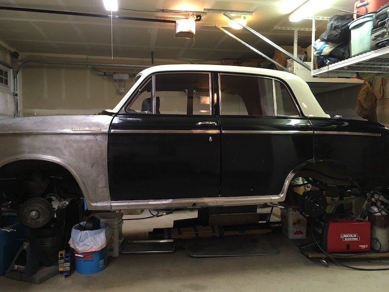
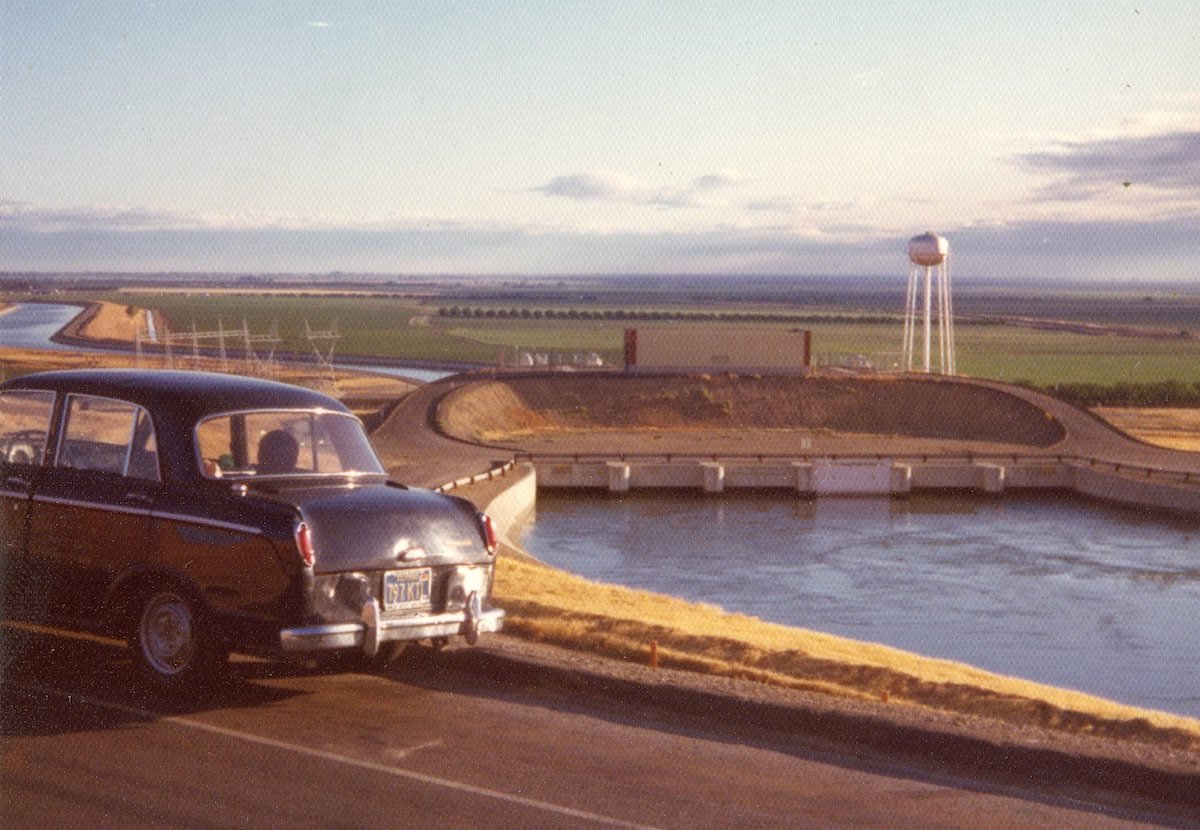
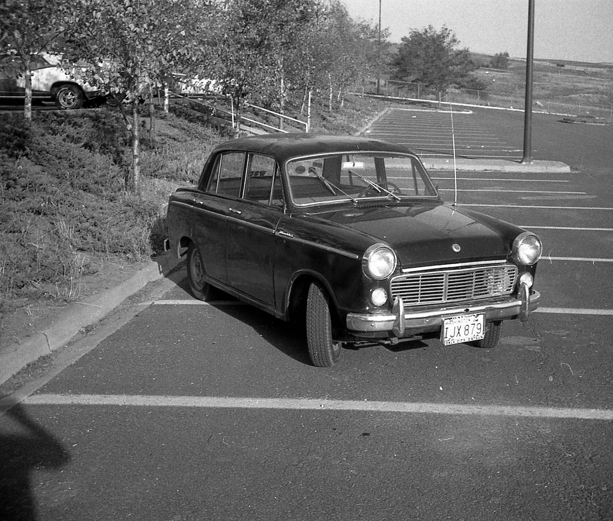
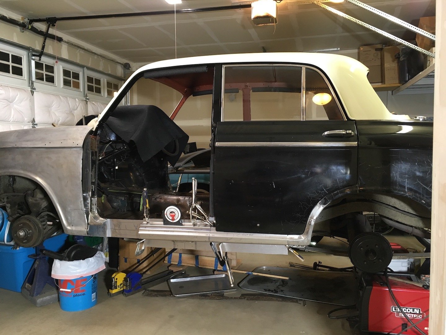
This is my Datsun Bluebird "de-rustification" project. This Bluebird is a U.S. specification 48 HP left hand drive 1961 PL310. It is the same as 1959 and 1960 310s. It is much different with respect to the drivetrain than late '61 through '64 models with the 60 hp engine, all synchro transmission and beefier rear axle components. I've swapped in most of the later model drivetrain though. The overall project been on and off again for years, decades actually. I have 44 years of my ownership history that I can present separately in a discussion thread along with this build activity. Previous historical "major" repairs included bumping out the roof panel in the late 70s due to a prior owner rollover accident. The rust work however is relatively new since early 2018. Photos. My earliest photo of the car is alongside the aqueduct in the California San Joaquin Valley in June 1975 and then Pullman, WA October 1975 . The latter photos are current covering the inner and outer sill panels fabrication, fit and weld work currently in progress. As time permits, I'll go back a year and begin describing the work and discoveries along the way to date and continue from there. https://oldschool.co.nz/index.php?/topic/60267-marts-pl310-61-datsun-bluebird-sedan/
1 point
-
So i live in kaiapoi and i needed a car to fit in with the locals. This came up for sale on trademe without photos and i couldnt get a hold of him, till one day i posted on Dirty South advertising and got linked to the sellers profile. Went to look at it the next day, brought it. Basically when i was looking for one it had to be Column/Benchy so we could pack the boys in and go for a cruise. It has been in one family for most of its life and i am the fifth registered owner. Genuine 194xxx kms!! Here it is when i first got it. Discussion Thread1 point
-
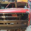
I think this thread is for 3 chassis ago. Yeah twin headlight with painted bumpers has always been the dream1 point
-
You would have to look into the laws in your area, ie here in Brisbane the law is vauge and some spray painting at home is allowed as long as it is not commercial. You have to look it up, It was legal to spray my car in the driveway and I asked/told the neighbours about it. I mean guys reseal roofs with spray in open atmosphere, I have seen the exterior of homes spray painted. Case by case for your council. Bling phosphoric acid is not hard core, I buy the bunnings shit and dilute it a little further depending on the job. It doesn't sting the skin and fuck all fumes unless you boxed yourself in with a bath of it working. You can do the same thing with citric acid or vinegar for sure but the phosphoric seems to be just the right zing for panels where it takes 15-30min instead of 4 hours, when I was soaking shit in citric acid baths it takes 24-48h to work. Unsure about anything else as using acid is the gold standard as far as I have learned. As for spraying safety I had looked it up a millon times but looked again. Modern 2 part epoxy primers are only considered mild irritants and only fuck you up over long term exposure without correct PPE which can give you allergic type reactions, they do not cure with isocyanates. They are just as shitty as exposure to single stage solvent curing paints basically so wear a mask and its all good. Its the polyurethane ( urethane primer, single stage top coats,clears etc) that cure with isocyantate and are considered extra death spec which gets absorbed through the skin and can build up toxicity.1 point
-
Take care spraying epoxy - get the right protective gear. When I started spraying I stuck with single stage paints for safety reasons.1 point
-
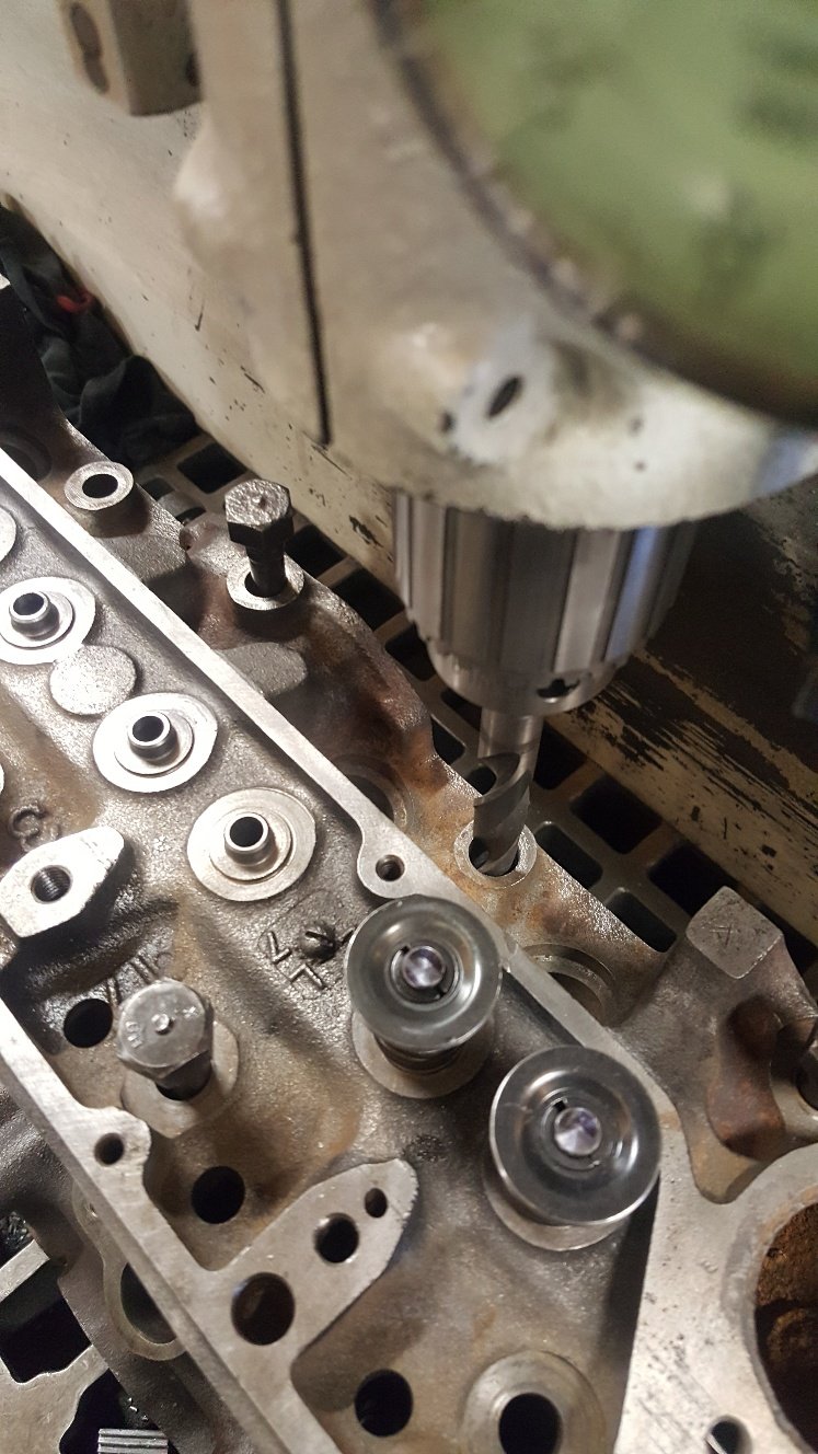
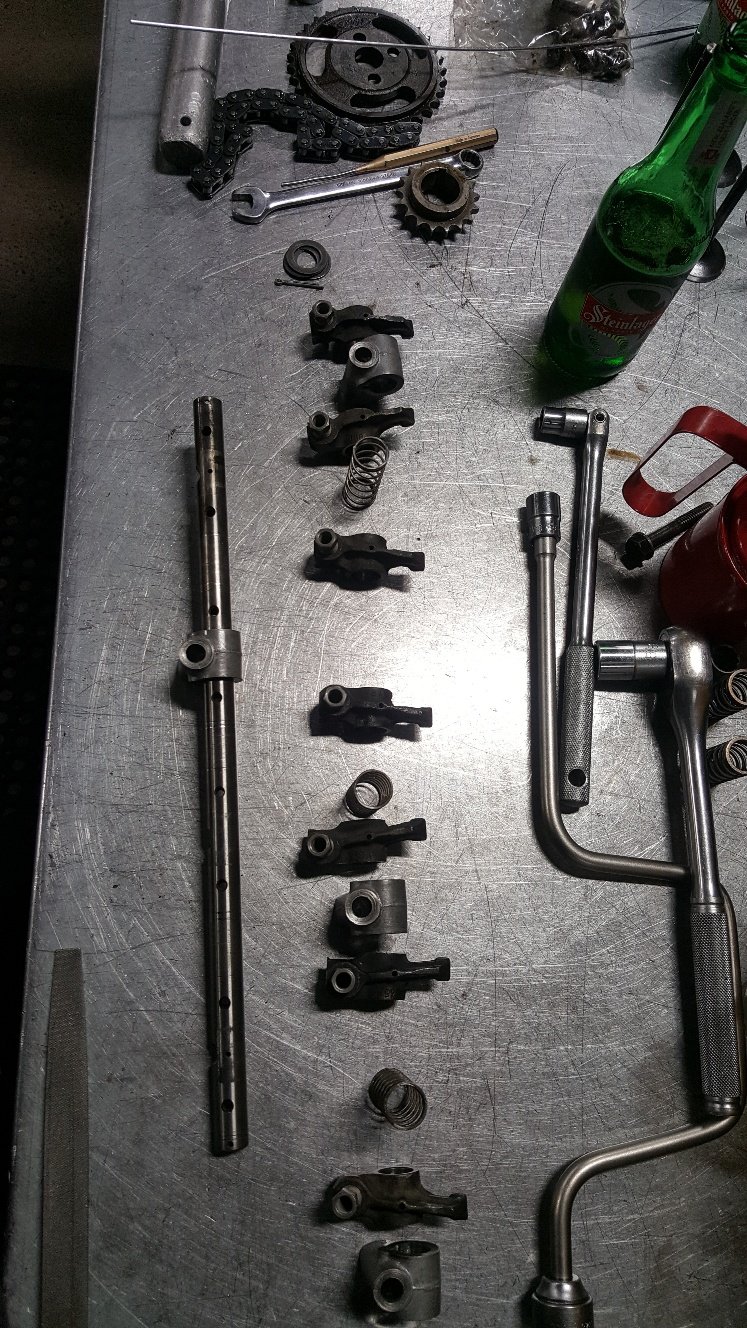
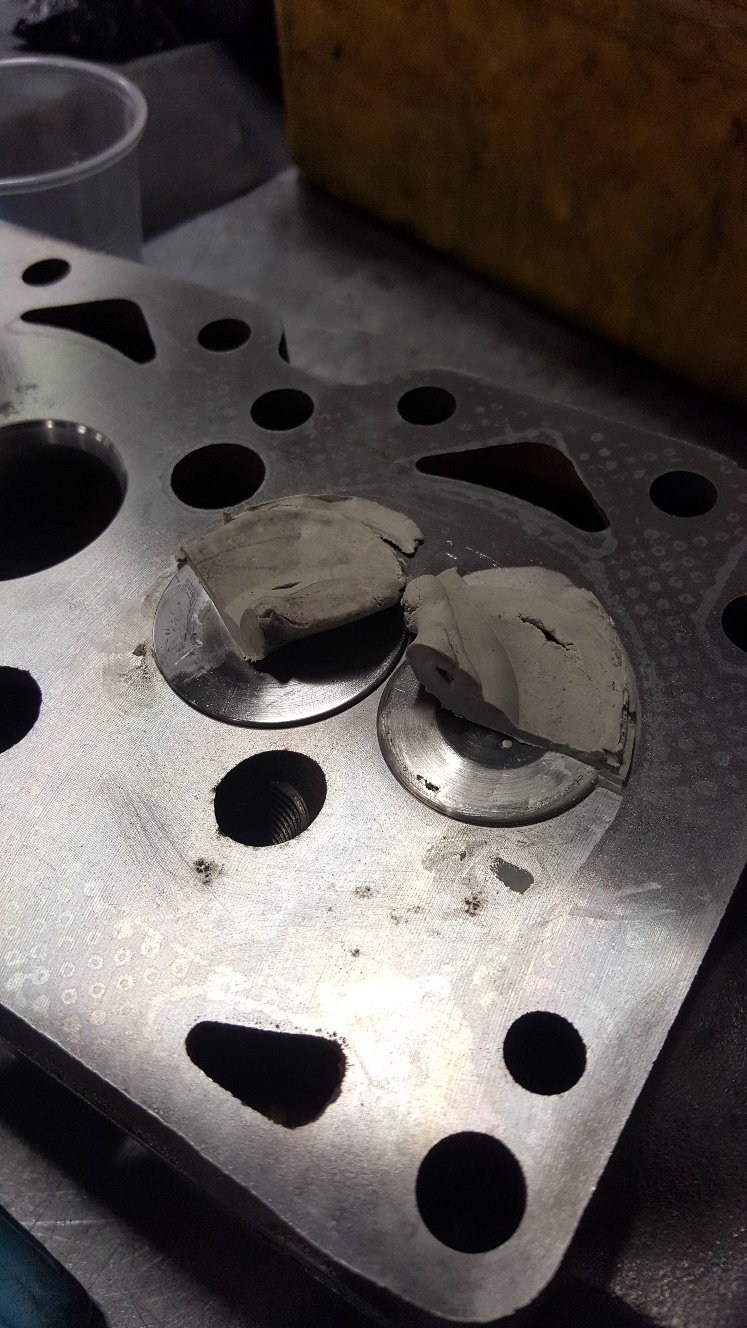
With the head sorted i can put the camshaft in and check piston to valve clearance. But first I need to dowel the head to the block. These old beast come from the factory without any location other than the head bolts. So I center off one of the head bolt holes and drilled it to 14mm. Then bolt the head one without moving anything and drill the head bolt hole out to 14mm. Then fit the head on the dowel and drill the other head bolt hole for the second dowl. So dialed the cam in. Then bolted the head on and found my rockers where a little worn so gave them a tidy up. Forgot to take pictures of the head fitted. But basically fitted the head, put two layers of plastersene on top of the piston in the valve cut outs. Then turned the engine over to get the valves to in print into the plaster. Then I cut half the plaster away to see how thick it is. This gives you a good indication of the piston to valve clearance.
1 point
-
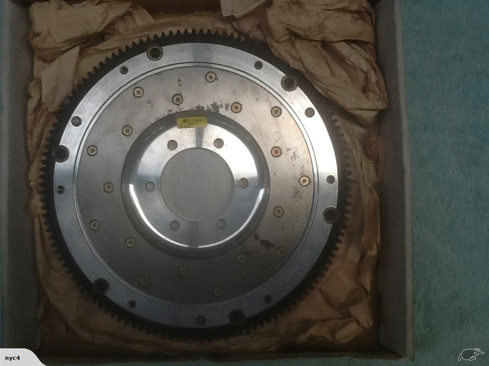
I think it is a Fidanza, either that or a well-made copy. It had the Fidanza part number on the box and looks like all the pictures online so I'm fairly convinced. It also has an SFI certification sticker on it and they're of course impossible to fake. The only reason I think it might be a copy is it only cost me $250, admittedly second hand but it is in essentially brand new condition as far as I can tell. I'm absolutely frothing to get back at it properly, already looking at places with garages to rent while we've still got four months left on our current contract. Can not wait.1 point
-
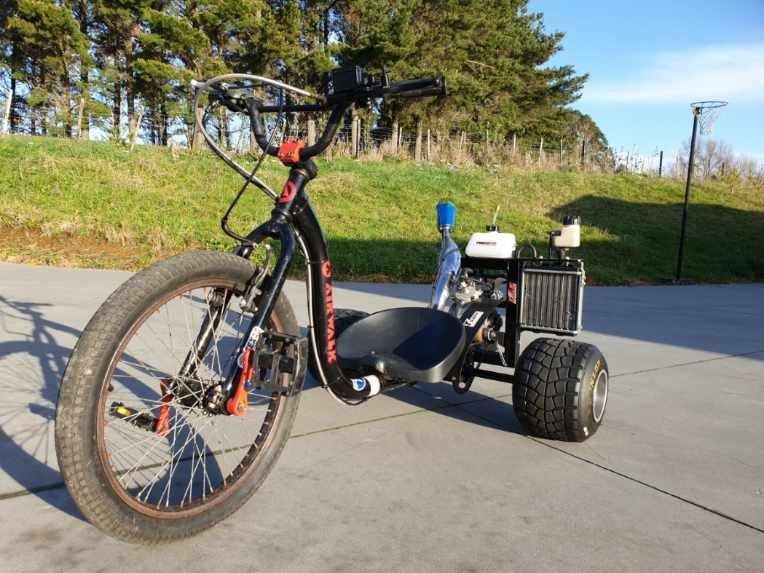
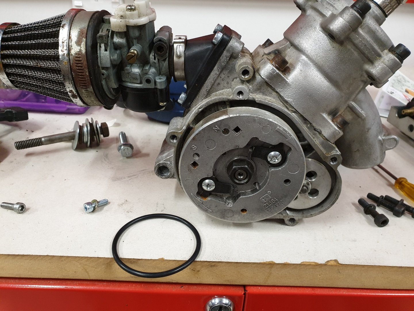
Drum roll...and finished it! Fuck yeah...stoked!!! Need to pick up fluids for it tomorrow and fire this bad boy up. 16,500rpm of 2-stroke awesome about to wake the dead!
1 point
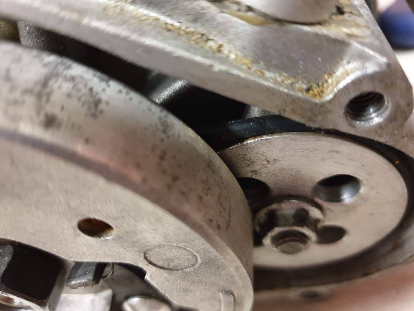
-
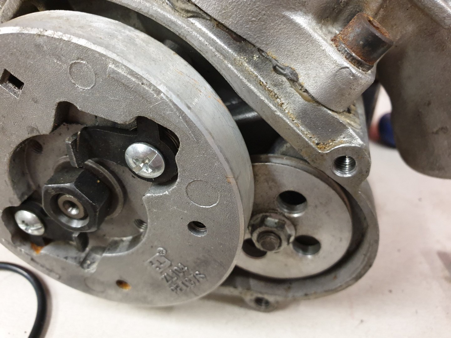
Turned my attention towards the motor again, while I'm waiting on this to dry: The motor drives it's own internal water pump via an o-ring as a drive belt. Over time, these stretch and your going to lose tension on the drive pulleys. As a precaution I replaced it, and side by side it had stretched quite a lot...so possibly a lucky save there! Said o-ring above. You can see the water pump pulley here (smaller one on right). And o-ring installed on water pump pulley and to the pulley that is behind the flywheel. Job done!
1 point
-
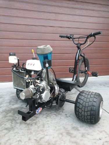
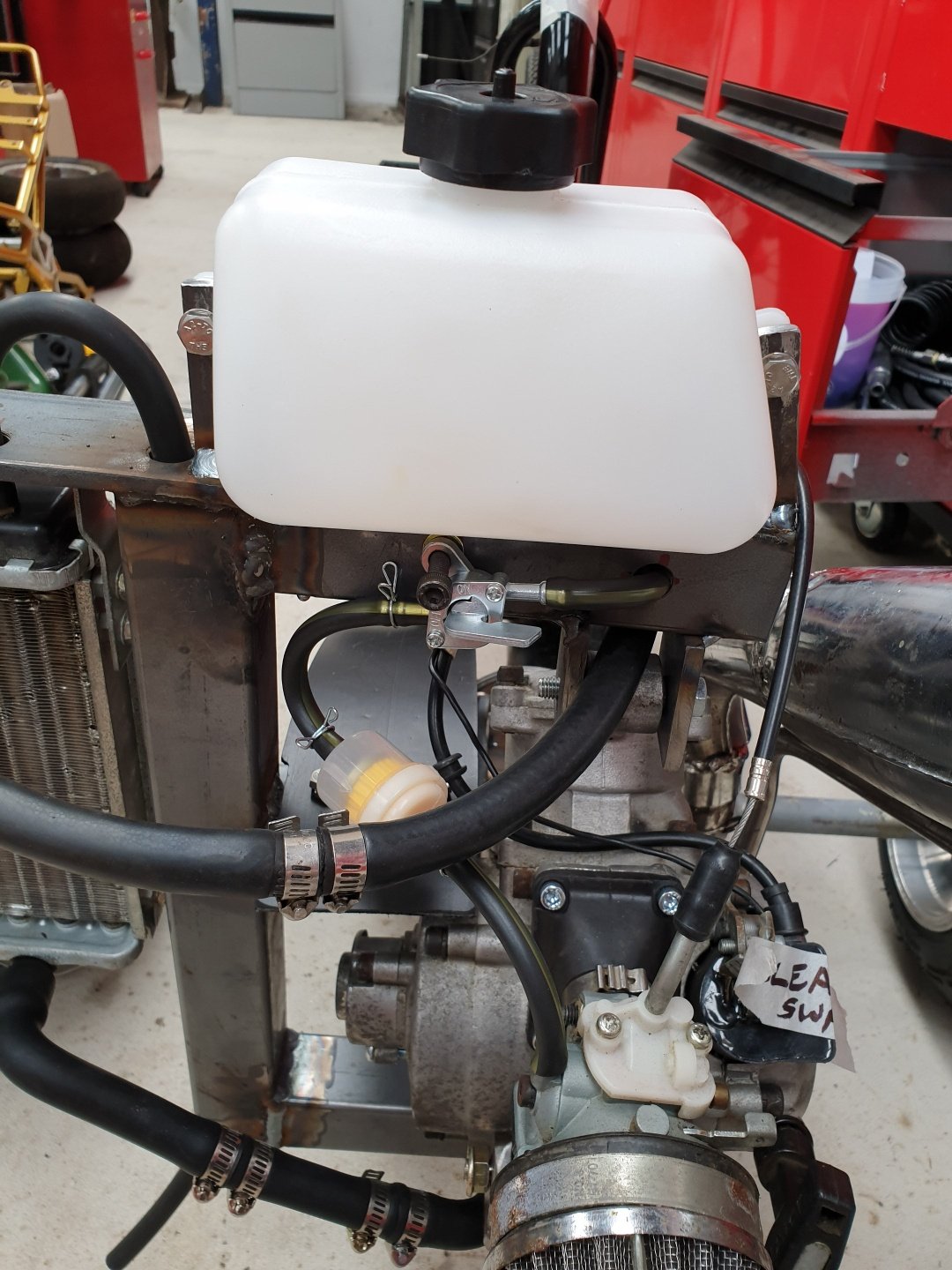
I'm confident it should actually just start up right now if I put fluids in it. Any excuse to use this awesome tool! Nutsert in place, holes step drilled for various purposes. Fuel tank mounts welded in place. All the plumbing done, fuel lines, tap, filter, throttle cable, hydraulic brake lines...all seam to fit and be right length. Next, take it all apart and paint it. Then final assembly.
1 point
-
replaced all the lip seals on the crank and both ends of the gearbox. tapped and fitted some 1/8 NPT hose tail fittings to the fluid cooler lines and then i put the box in the car. it fits. dont have the gearbox crossmember in yet, ill make the mods to that tomorrow night. 2019-08-08_07-51-57 by sheepers, on Flickr 2019-08-08_07-51-47 by sheepers, on Flickr1 point
-
Finishing these ones before I start new kits.
1 point
-
Possibly old moulds that Italeri have acquired from somewhere. Not car related, but I got my hands on an ancient Frog 1/72 Beaufighter kit a long time ago. The moulds were past their best by the time that kit rolled off the line, and it took a lot of work to bring it up to scratch... Fast forward 5 years and one of the no-name brands that popped up in the mid 2000s released a Beaufighter kit clearly made from the same moulds as the Frog kit had been nearly 50 years earlier - Same flaws in the same places, but magnified further by the extra age.1 point
-
1 point
-
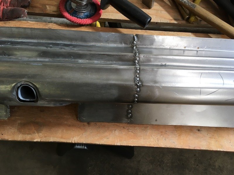
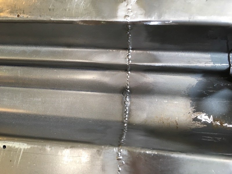
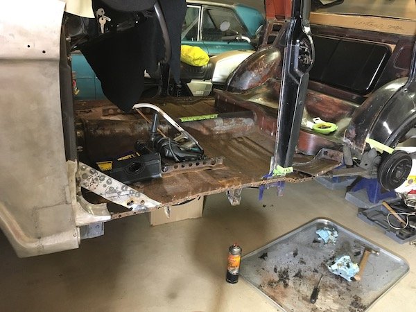
Continuation of the previous post with several more pics. The left middle/side patching of the rusted trans tunnel. As it started out with the fore and aft sections already tacked in. Made a patch to try and duplicate the existing contours and set an upper tape trim line. The black sharpie line was only a guide for torch heating the metal and asphalt undersealant on the other side to get it soft and scraped off. I didn't want my cutting tools getting gummed up. Cut the rotten metal out. Rubbish now. It would have been difficult to get a good weld against it. Cleaned up the surrounding metal. Did some test fitting to determine the trim of excess material on both ends. Final fit and ready for tack welds. Initial tack welds completed. With all the surrounding metalwork taken care of, I proceeded to cut the left hand side floor out. The seat mounting bracket will be salvaged. Same for the reveal or surround for the hand brake penetration. The underside. Planned underside salvage items include the long fore and aft 'Hat" section and body mount bracket. Other brackets are too badly bent, battered or rusted to be salvaged. There are four other simple flat or nearly flat parts that will be duplicated. I'll double up on whatever details are made to be ready for building the right hand side of the car. Never made a scratch built floor before, only patches and brackets. It's going to be challenge with the wide stiffening beads, elevation changes and 3D shape near the mid-body mount and rear footwell. No guarantee of success. Some random extra pics. Sleeping Bluebird with dreams of many road trips past and to come. I've now completely used up a four foot by eight foot piece of 0.9 mil thick sheet metal and need to buy more. Still got a long ways to go just to get the left side of the car finished. I'll post again later with more progress when I get the left side finished. It could be three, maybe four months or more. Discussion: https://oldschool.co.nz/index.php?/topic/60267-marts-pl310-61-datsun-bluebird-sedan/
1 point
-
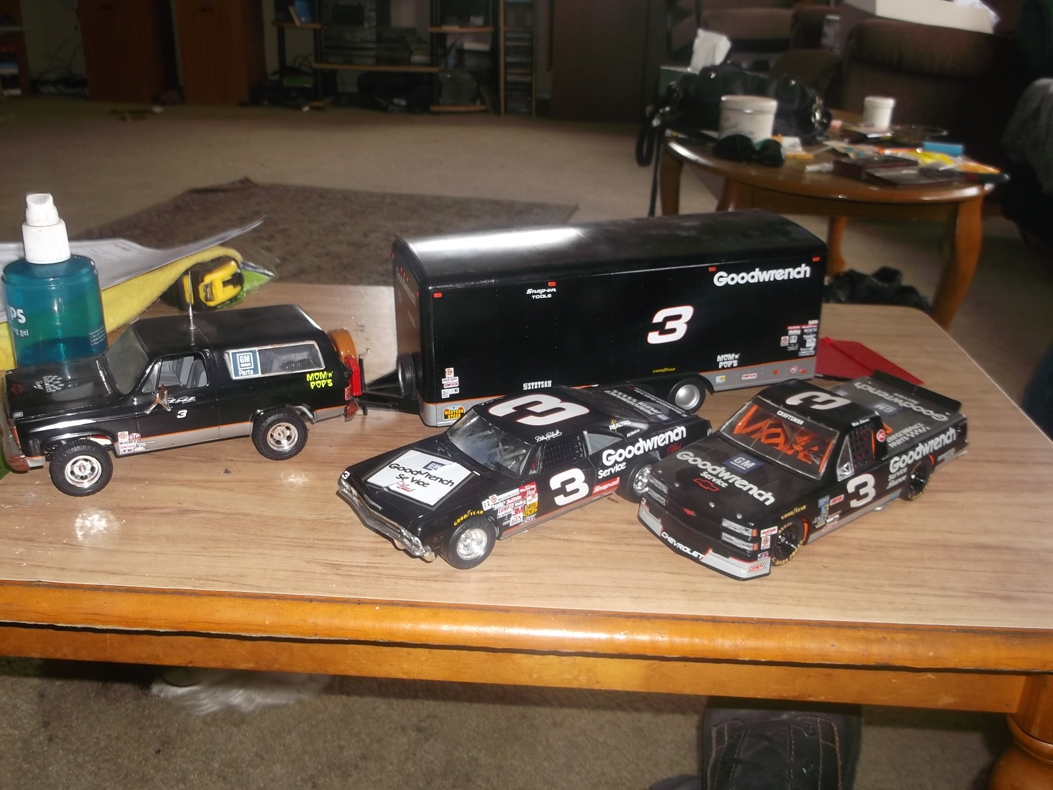
This is my first 1:24 car model I've just done recently. No mods, just a copy of the wife's first car.
1 point
-
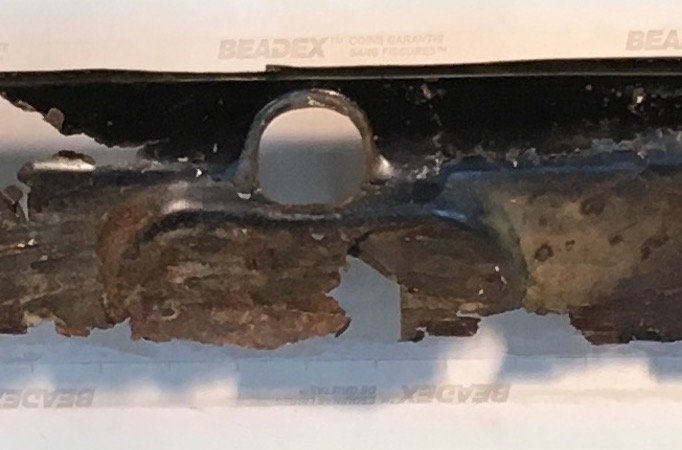
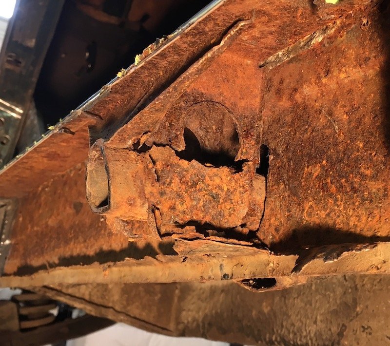
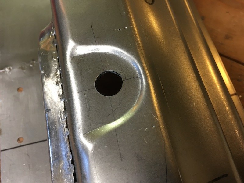
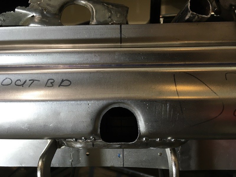
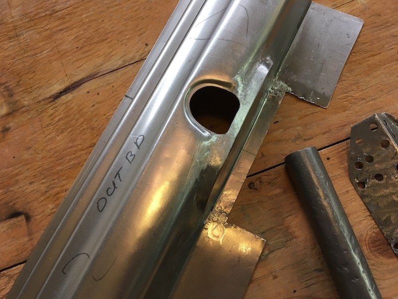
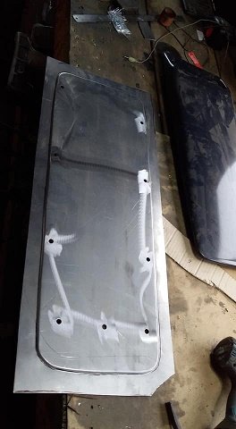
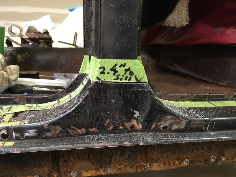
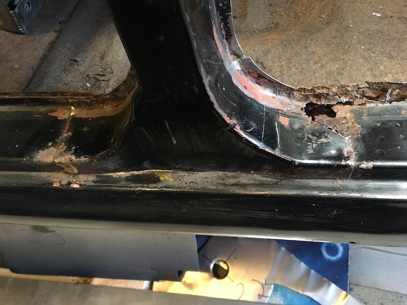
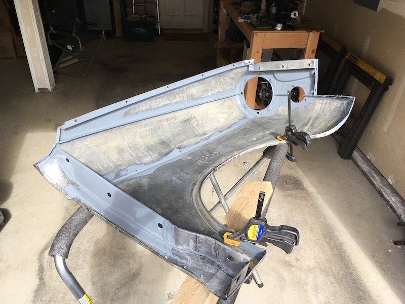
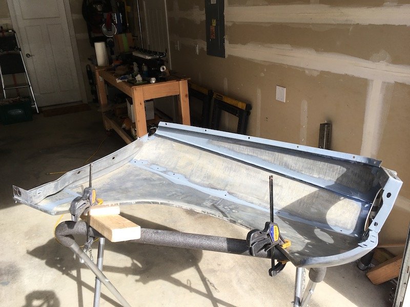
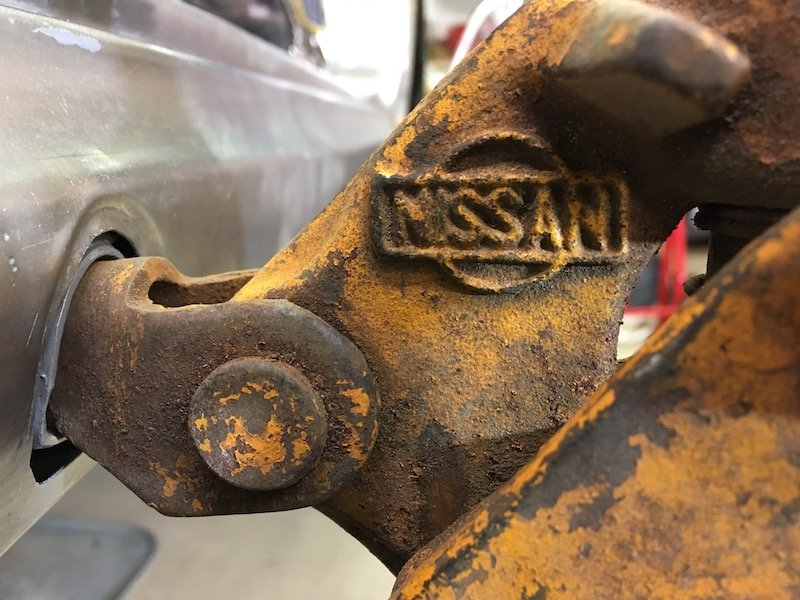
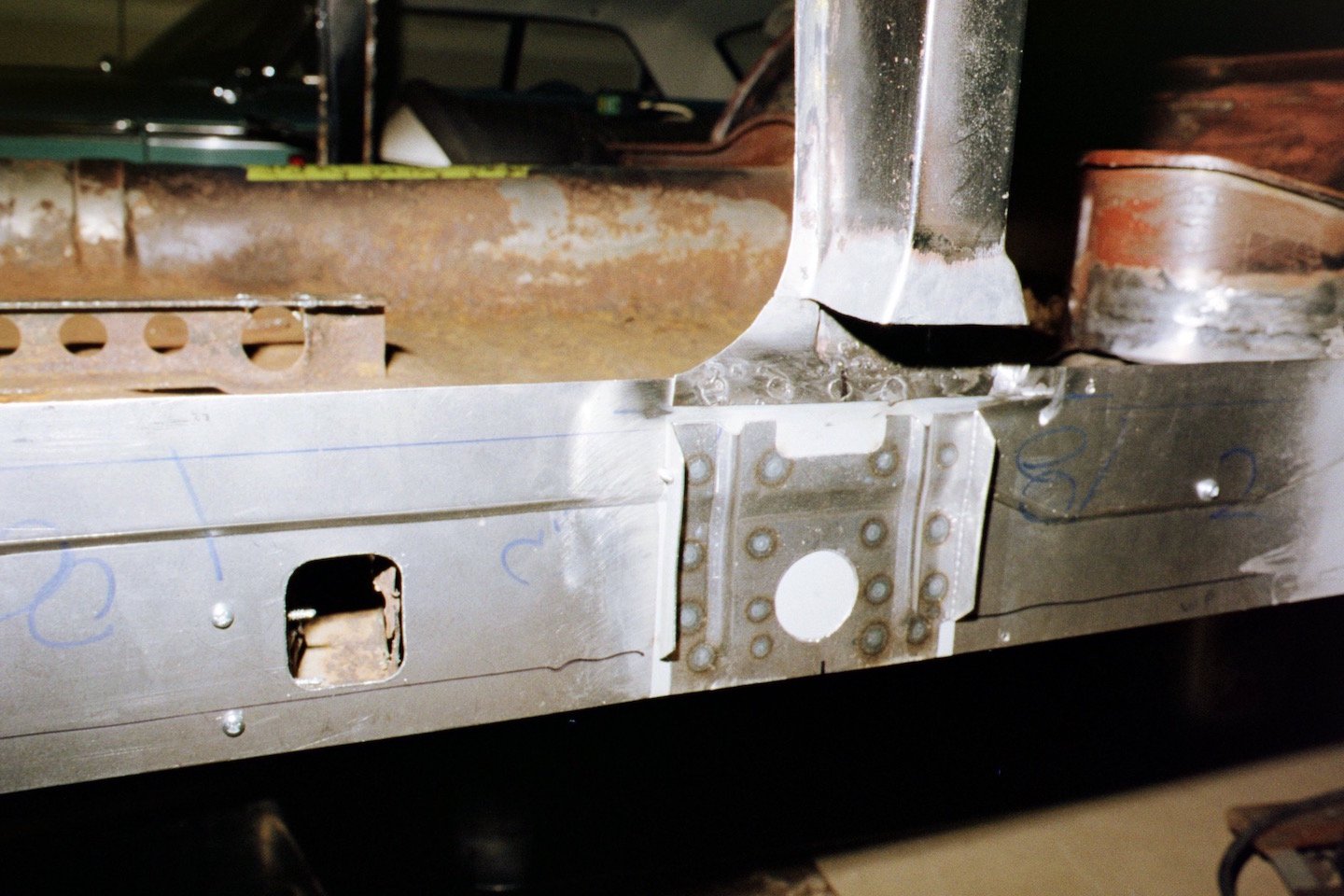
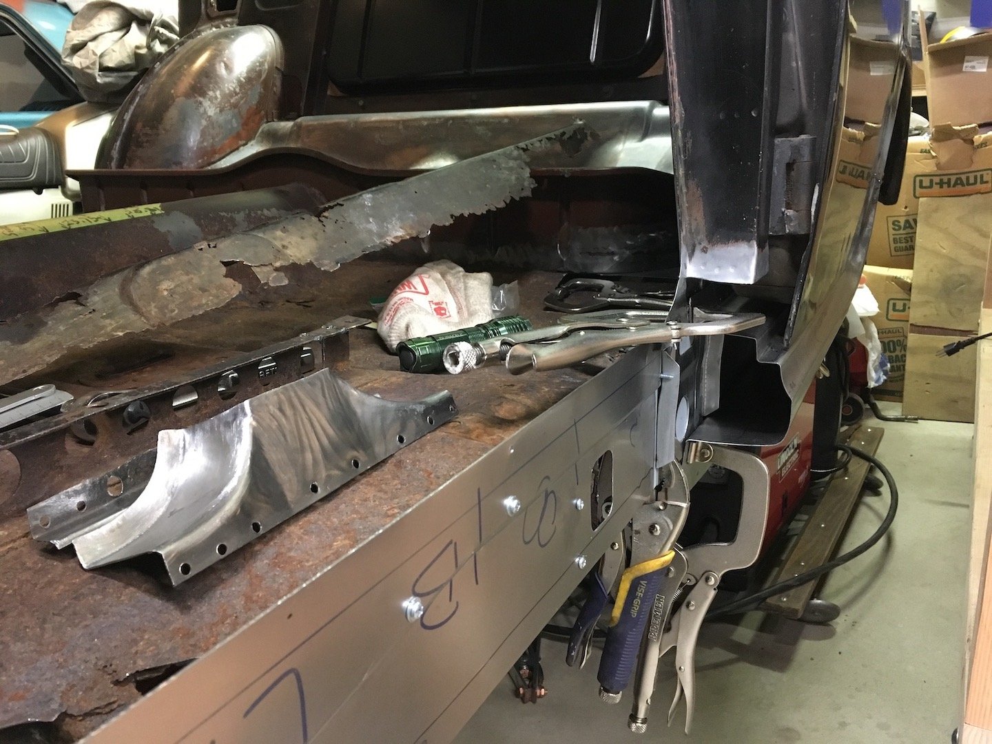
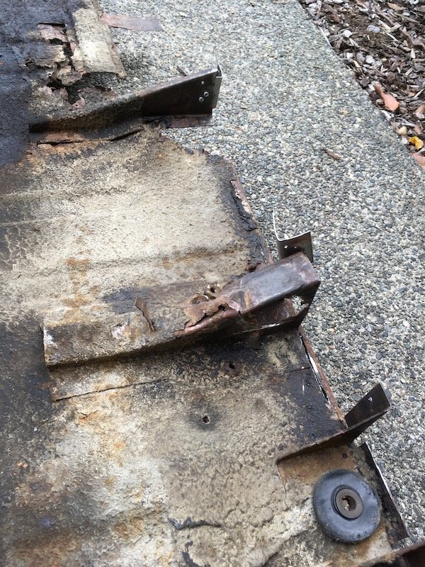
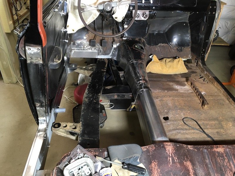
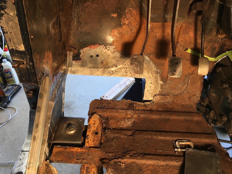
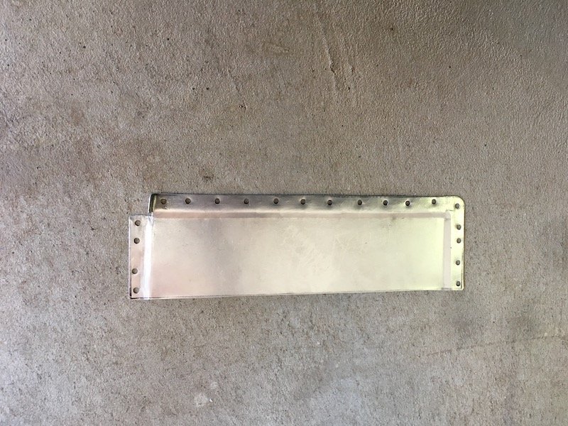
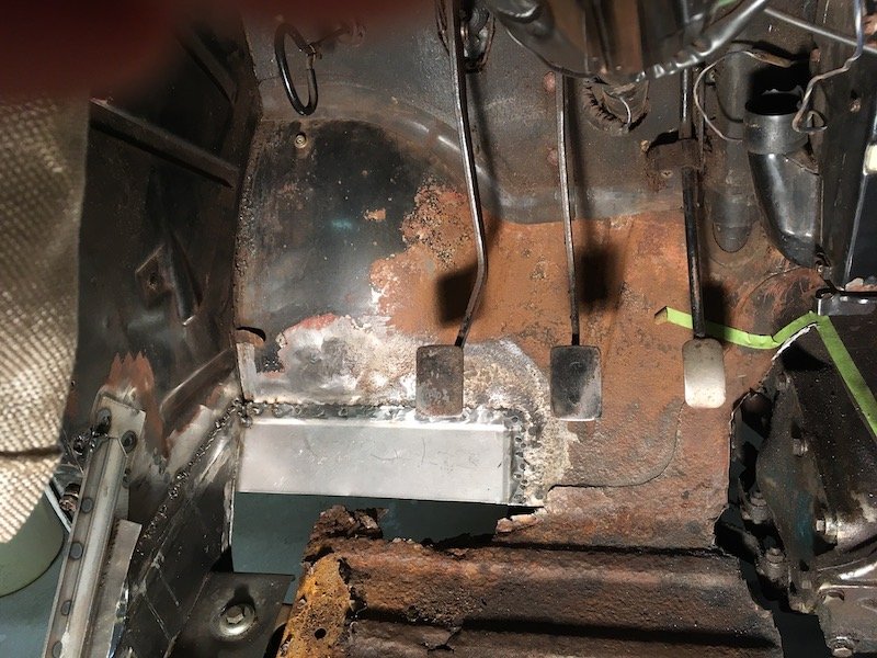
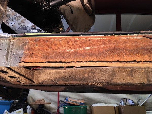
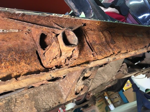
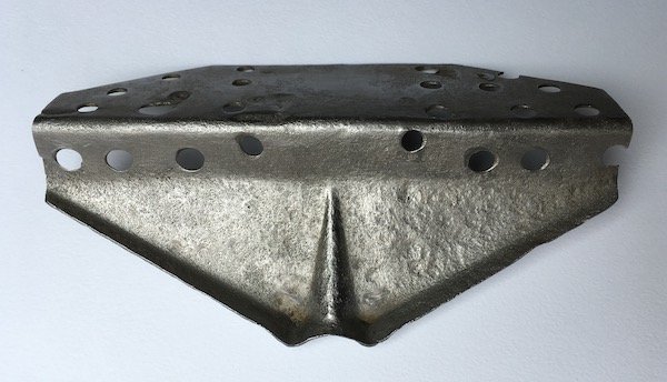
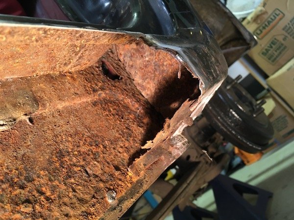
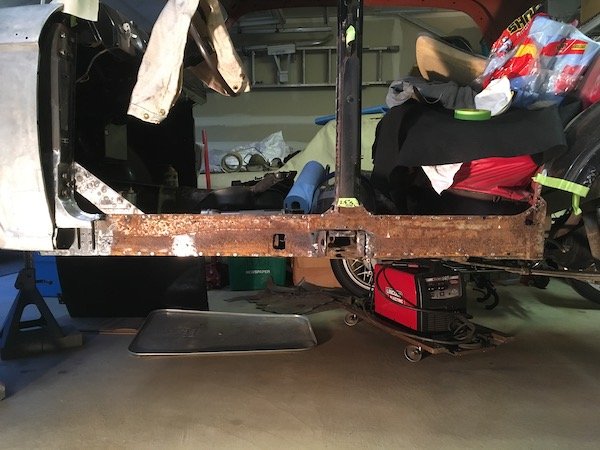
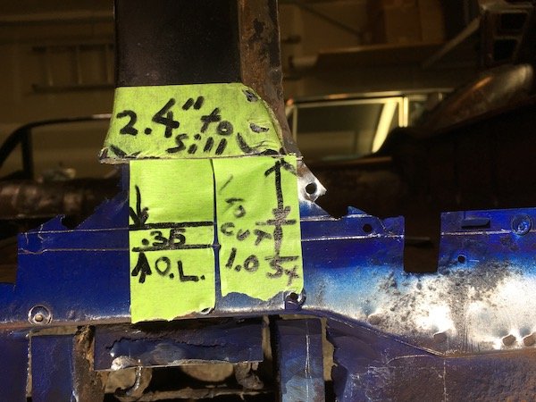
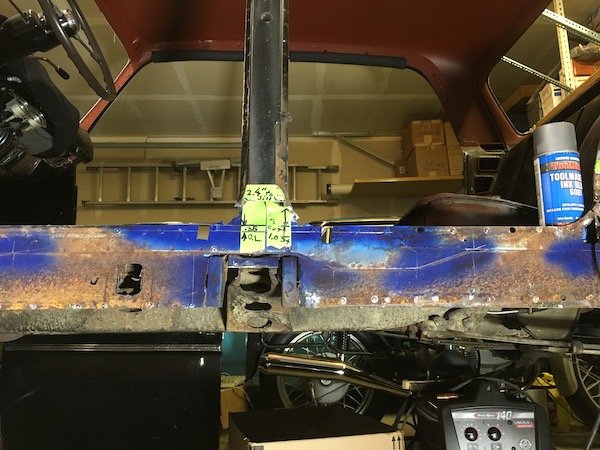
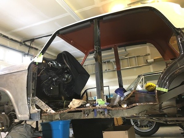
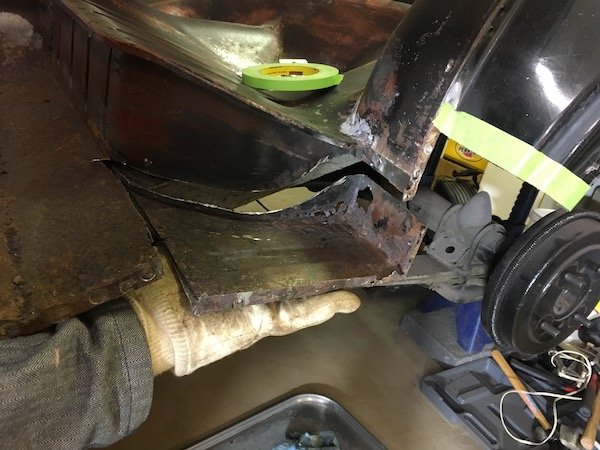
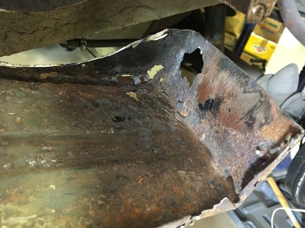
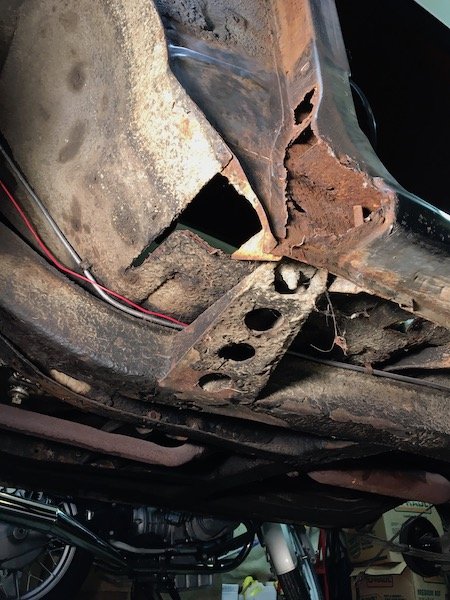
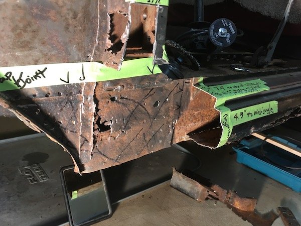
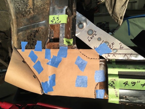
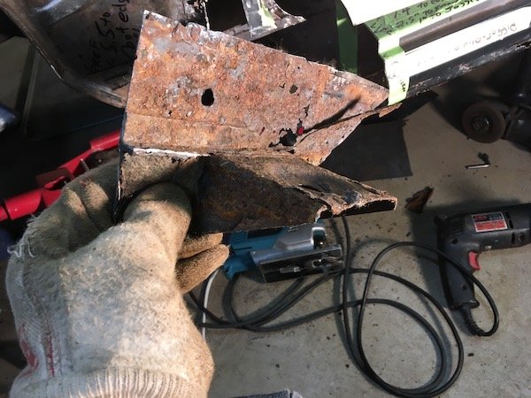
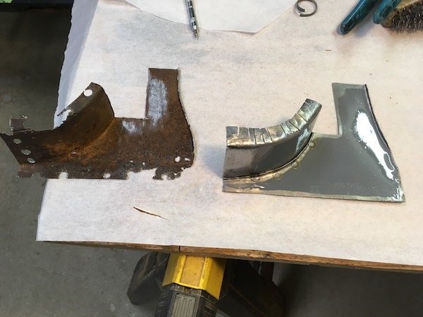
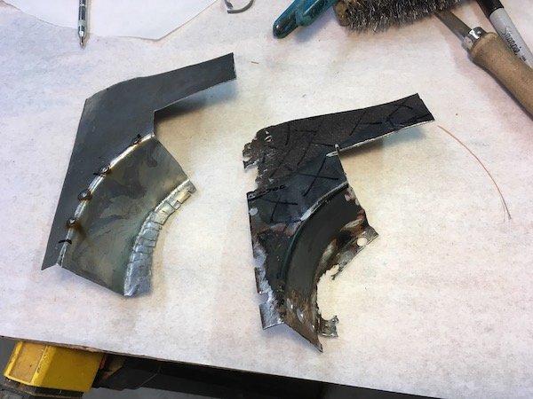
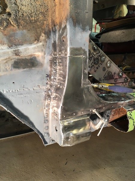
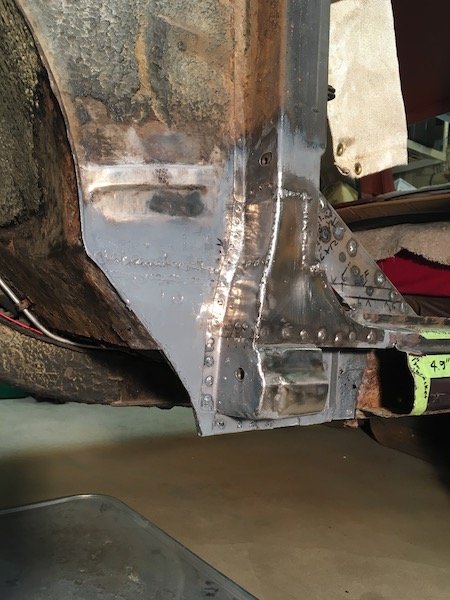
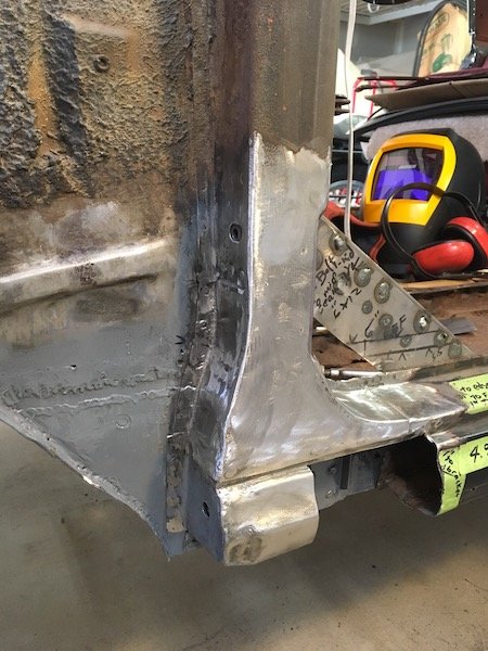
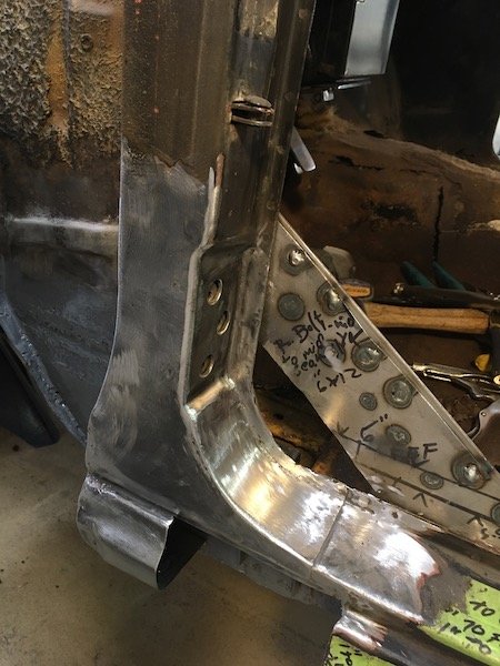
Removal of more rusted metal from the 61 Datsun Bluebird left hand side outer and inner sill, 'B' pillar, 'C' pillar and side of seat pan. A huge hole in the car structure is the end result. This gets very ugly and you may want to look away if at all squeamish. No need to panic! Almost of this is going to be replaced with new steel, but it is a very slow step-by-step process to make these parts from scratch. There is nothing here you can just go to your computer and order or even find in good condition in an auto wrecking yard. It is a heck of a learning process that will be applied to the so far untouched right side of the car. I get started by using electric metal shears, slicing and splaying open the outer sill for internal rust inspection and to understand what details are inside with respect to the side of body lifting point. I had hoped at least the upper sill and inner would be salvageable so I cut a relatively clean line against a tape edge at the body line. The outer sill immediately swung open at the lower pinch weld and then just falls off. Notice the slightly bumped out area below the body lift penetration point. This will be duplicated in the new steel panels later even though I may never use the factory lift jack tool. I do still have the jack but it is worn, unstable and deemed unworthy for safe use. It would either lose grip internally and slide downward suddenly, or the small base plate could kick out at the ground and punch the upper shaft end against the door and make a big dent. Maybe the old lift jack can be repaired and improved or maybe not. Sheet metal form detail of outer sill lift jacking point Eventually, the rusty inner sill is to be separated at the left next to the new 16g steel from the previous 'A' pillar repair and new metal lapped in at the back side of the gusset shown. If you look closely, you see the fuel line and wire to the electric pump. That line is soon removed to avoid a fire hazard. Moving further aft, we see the reinforcing structure around the lift pipe, or what remains of it anyhow. And behind that what I call the joggled gusset. This upper gusset, the near one with the three ribs, is heavy gage steel and salvageable. I thought incorrectly, that to remove the upper part of the sill, that the upper gusset would have to be separated first from the pipe. Actually the top of the pipe is not welded to the upper gusset at the notched contact point. Only the side brackets are welded to the pipe and they are weak enough to just pull apart from the pipe. I could have just lifted the upper sill right off once the regular pinch welds were drilled out. The salvaged lift pipe gusset plate. I ended up with a lot of holes from spot weld drill outs that will be used for plug welding later on. This is the joggled gusset plate that is on the opposite side of the inner sill with respect to the body mount bracket on the other side. This gusset is deemed too badly cratered and rotted and will be reproduced. I cut it out before removing the inner sill by cutting around the perimeter after a futile attempt to search out and drill out all the spot welds. Things aren't looking to good above at the base of the 'B' pillar. Lots of otherwise hidden rust damage. I'm going to cut 'B' pillar base off and repair. The damage and repairs needed to the now cut off 'B' pillar is shown in the light. I subject the 'B' pillar to an electrolysis bath to remove bulk rust and identify the salvageable sections. A lot of it is still good and will be cleaned up and reused. Portions near the pinch weld are bad and the flat horizontal section deep inside is shot. Outward facing sections are perfectly good. Jumping ahead here a little bit since I did not have a good pic of the freshly removed gusset plate. As you can see, it was total destruction to remove it. A real light show with all the flying sparks! Shown above is the newly made replacement. The joggle or step was made under force from a hydraulic press and an opposing stack of offset steel bars. The aft end inside the sill is heavily cratered and holed. Thus I go to the extreme of cutting off the 'C' pillar, aka dog leg, for complete repair as the hidden damage inside is total rust out which will otherwise just continue. Where there would be an end of sill block off plate in the far back is really just rust powder stuck to the asphalt undercoat. At the lower pinch weld, the flange of the outer sill moves upward leaving just the inner sill plate poking down about a half inch. Why? Just looks a bit odd. Probably to match and fit the slight difference in contours at the 'C' pillar. The now cut-off dog leg ('C' pillar base). About 60 percent or more is perforated or too thin to reuse. This part proves difficult to reproduce. It is still not quite right after patching it up section-by-section off the car. I tried, and will tweak it a bit more now that it is welded back on the car. I might do it differently when I go to work on the right side of the car now that I know which areas should be cut out. The now fully exposed inner sill plate. This was a bit of fun. Before drilling the spot welds and removal, I cover all the step contours with blue machinist paint and scribe on the metal the intersection points to permit accurate measurement of the sill. The inner sill steps out about a tenth of an inch where the flange of the floor is butted against it for nested fit. In addition to recording measurements prior to removal of the inner sill, I make a paper overlay as a secondary backup to sometimes flawed note taking. I've also made a full size drawing on mylar as yet a third method to help reproduce the part. Key measurements at the 'B' pillar overlap (O.L) and inner sill. It's starting to look pretty messy and getting worse soon. Inner sill is drilled of the spot weld connections to the floor flanges and removed. The underfloor brackets are cut off at their flanges because these brackets are severely beat up from impact damages. The bracket for the body mount is planned for reuse, if it is good, so the flanges are left intact. Not reusable! As final act, the side of rear seat floor pan is cut out. Is there a name for this thing? This proves to be a relatively easy and fun part to reproduce because of the straight bends and box shape. Just a little challenging to butt weld into the side of the seat pan later on. A rust hole big enough for a mouse to climb through. And they did, sometime stockpiling grass seed and such here and there. And now the huge ugly hole in the car! A preview of making new parts and closing this chasm up. Making left and right hand parts where possible. I'll probably focus on the inner sill next post. More later.
1 point
-
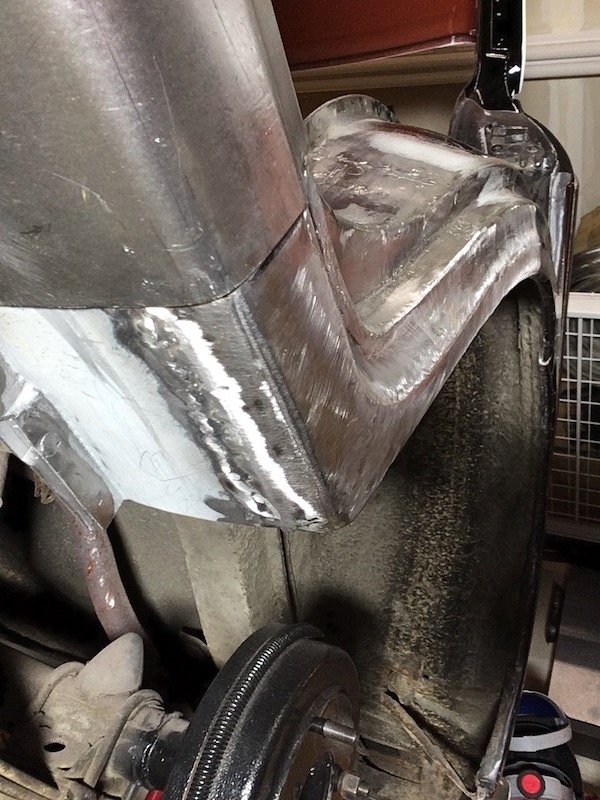
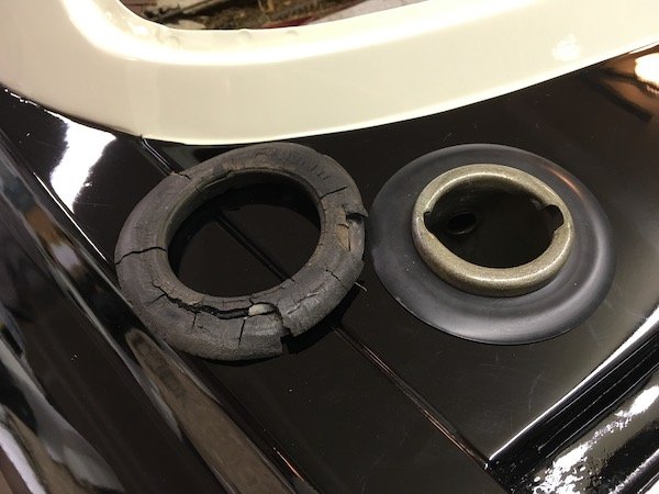
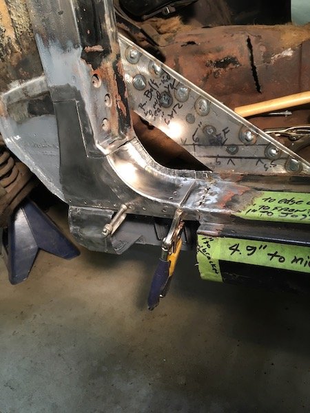
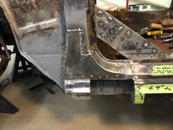
Repairs to the 61 Datsun Bluebird left hand side 'A' pillar (or post) The starting situation. More than a little rusty. Several portions are completely gone. I started by making reference measurements Cutting the remainder of the forward sill stub off Reinforcement was added before cutting the inner sill plate out. Making a paper template for an inner sill patch Cut it out Sizing up some 16g steel sheet Finally the patch, gusset plate and body mount bracket (on inboard side) is welded. Had to do it twice as it was placed crooked the first time. Still learning how to weld with the MIG. I should have turned up the heat for these welds against the 16g, still a bit cold with too much build up. The rest of the inner sill going aft will get cut and replaced later. Inboard side Did some sketching and cut out some flat bits to make the rest of the pillar They may not match perfect, since some of these cover undefined areas, but they are better than empty air space! Beginning of the outer sill forward stub Forward sill stub inside Initial fit checks, and adjust and fit and repeat Added the floating nutplates A view of an original style retainer for the square nut. Bent over 180 to get a wrench on the nut after torching a hole in the inner panel. Notice only one tab is welded to the metal. From the right hand side pillar that is toast. The area is phosphoric acid etched and prepped for weld and protective paint where it can't be reached later Another viewpoint Beginning to weld it. Finally I'm getting the plug welds hot enough to penetrate well and lay flat. The reproduced upper bits. Didn't like the pie cuts but it worked Same as above, flipped over This metal work was getting tedious. For a diversion, I located a Nissan rubber grommet to replace the rotted rubber on left. This is the typical state of the rubber parts all over after nearly 60 years. Okay, back to the business of welding the parts onto the Bluebird... Prepping more of the soon to be hidden innards Get it welded! It's taking shape Getting there Now to just grind and sand the welds flush It looks not too bad. Solid metal again! The rest of the outer sill will be reconnected at the stub joint much later. Next posting will be removal of multiple parts, including; outer sill, 'B' pillar bottom, 'C' pillar (or dog leg) and remainder of inner sill.
1 point
-
While up at dads he walked me through giving one of my 1ggeu heads a bit of a tidy up. I pulled the valves out, all twenty f#@king four, then pissed four hours away sitting them on a wire wheel on a bench grinder cleaning all the carbon off. Next I degreased everything and waterblasted the bare head before pulling out old valve seals and replacing with new ($100 Ebay full gasket kit) Reassembled all the valves after lapping them in at some point, torqued the cams down and checked clearance to shims in buckets and all within spec, put my fancy wrinkle painted cam covers on and called it a day (better part of 3 days work) This was a bit of a low budget refurb to get one of these engines in and going for Toyota fest which is sometime around the end of March. Was also good to learn how properly disassemble and label everything to go back in order to the point where I'm fairly confident doing the two others I have in stock which I'll have resurfaced and acid dipped professionally.1 point
-
Getting close now! I got a new center console installed. It's from a KE35 SR and looks the tits I got some SSR 13 x 7 meshies with 215/50 tyres on them Then i decided to tackle the bonnet. it took 3 days.... crikey. Sand Fibreglass bog: More sanding and bogging Guidecoating: More sanding and spot filling I attacked the underside with a wirebrush and then some cans out. Etch primer -> black gloss -> clear coat And painting! Left todo for WOF: Install seatbelts Install wiper linkeage Carb tune Wheel alignment Build discussion:1 point
-
This weekend I did some wiring which seemed to have decided it didn't want to work since disassembly, to be fair I didn't check anything before I ripped it apart so hard to be sure. 1) Fixed the reverse lamps on the rear lenses to work when in Reverse gear 2) Rewired the KE30 loom to be of KE35 pin layout type, and run and rejuggle new/existing wires to the cluster This is for the reverse lamp, it's a different setup from the K40 that came with the car so had to to do some rejigging with the wiring. I don't have any new terminals so just chopped up some old ones, soldered and heat shrinked them up Tired of looking at this awful bonnet, I brush painted it with black epoxy paint. If I decide to fix all the errors with it one day, I will. otherwise it can stay like this until I find a new one that isn't so buggered I also had a nice VDO tachometer I thought would be marvelous in the cluster. This water gauge too. I thought I could just get it all in there and swap it out for a VDO one later on After chopping and slicing, pulling things apart it came together only 30% of these wires are used, but I thought I would just put them all together anyway to keep them nice and tidy. This is a 24-pin ATX plug most commonly found in computers. I've got loads of these around and thought what a good way to assemble it all **I have two of these clusters so I can always go back to original if need be!!! Before: After: So now I have a very accurate tacho, which looks pretty sweet and a water gauge to know how hot my baby 4k really is. _MG_0379 by phillipbaines, on Flickr it's crooked... I'll fix it when I get the new VDO gauge till next weekend! Build discussion:1 point


This leaderboard is set to Auckland/GMT+12:00