
Leaderboard


Popular Content
Showing content with the highest reputation on 11/09/19 in Posts
-
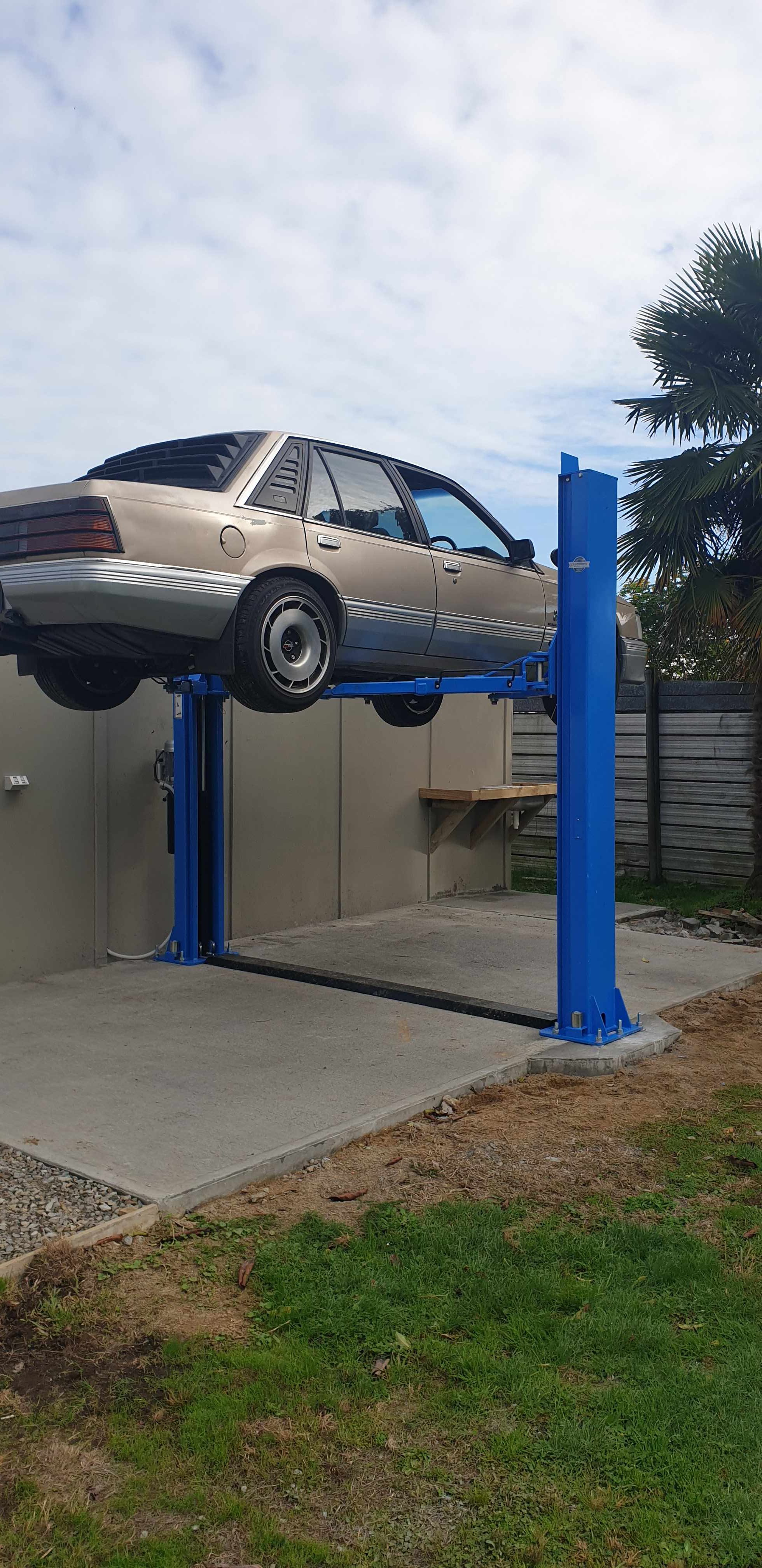
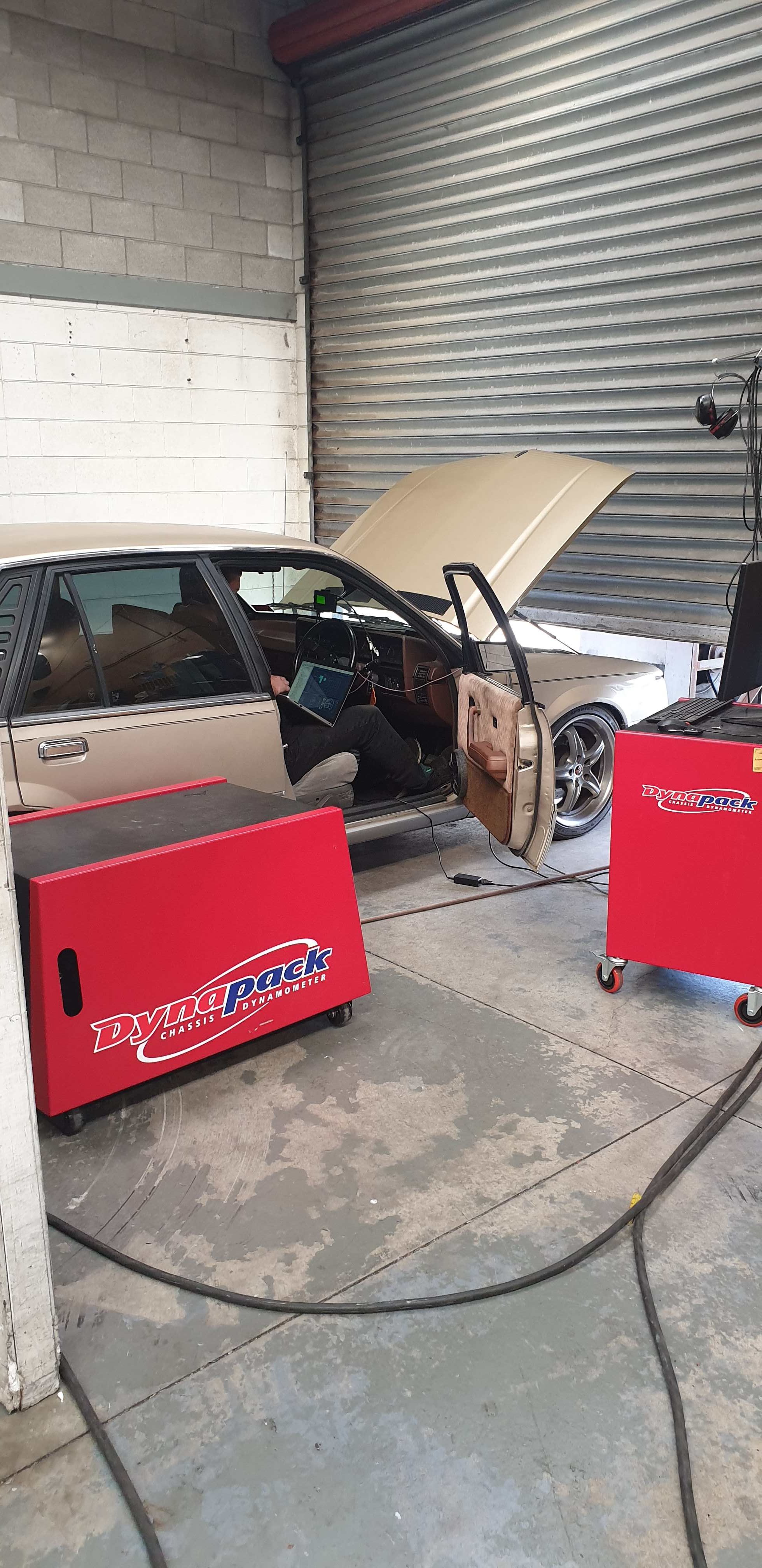
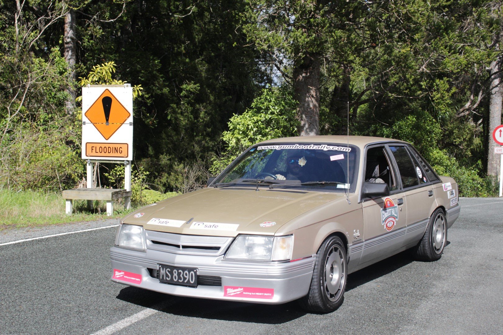
Passed clean sheet thru cert so stoked with that, brought myself a new toy so wish i had done it sooner. Took it up to Protune to chuck on the hub dyno... and my waste gate is too small, spiking 18psi of angry boost pixies at 3500rpm, aiming to run 7psi base with control up to 12psi to avoid splitting the crank from the block, ah well least the tune is now safe till i can fit up a larger gate. Oh also the camaro t5 gearbox i had fitted was stuffed so in a week had a commodore v6 t5 input shaft modified to fit, fabricated a new mount, bolted that up last wednesday and drove 1200km around northland for gumboot rally over the weekend, which Im super happy with how the car went, super responsive and torquey down low even with a low MAP/RPM limit, plus all the Spooley turbo noises
 18 points
 -
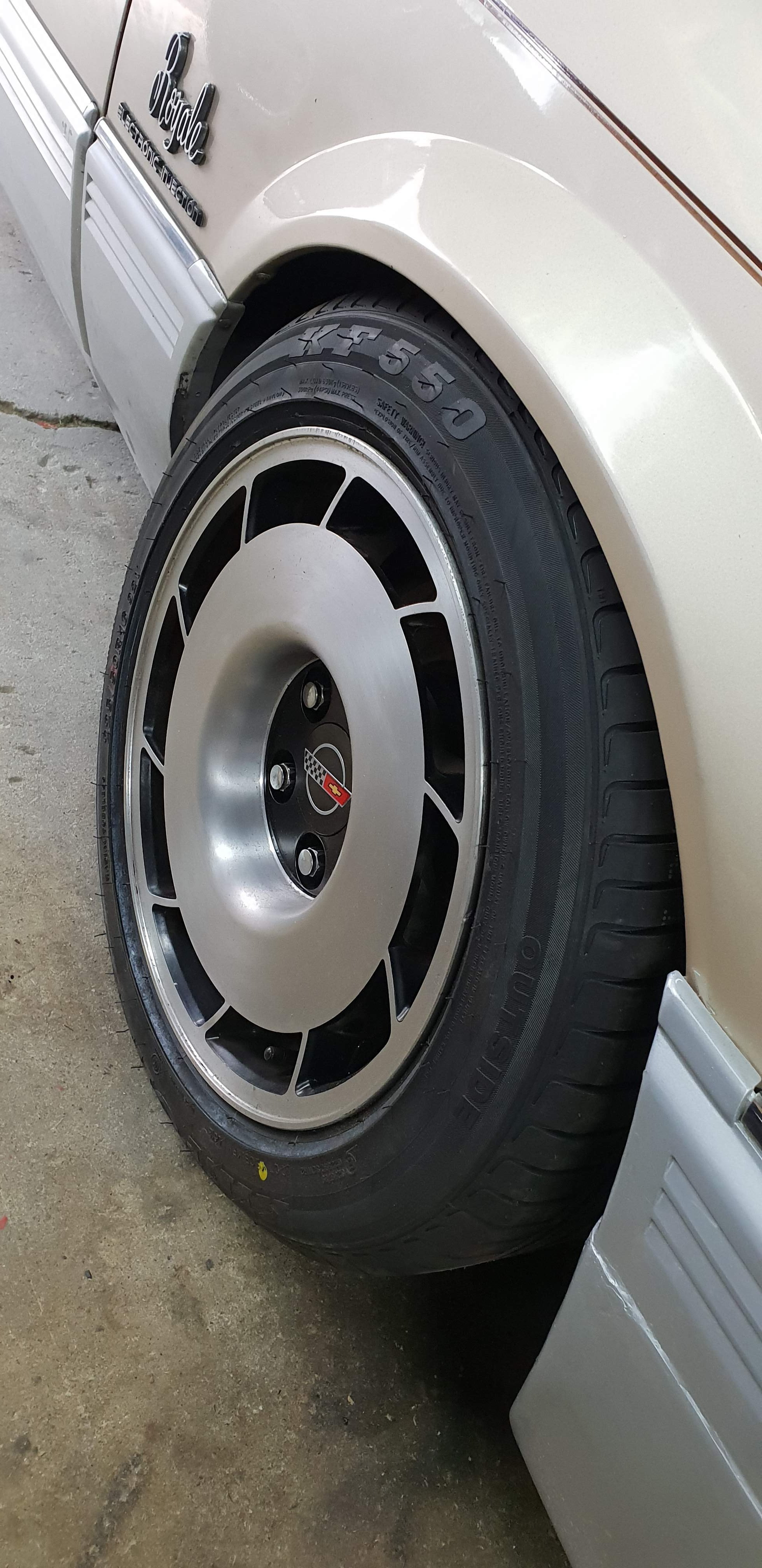
got it all pieced back together and running ready for Cert and a tune, also picked up a mint set of 16x8.5 &16x9.5 Vette wheels
8 points
-
Handlebars part 2 Muffler8 points
-
Make seat base Wiring8 points
-
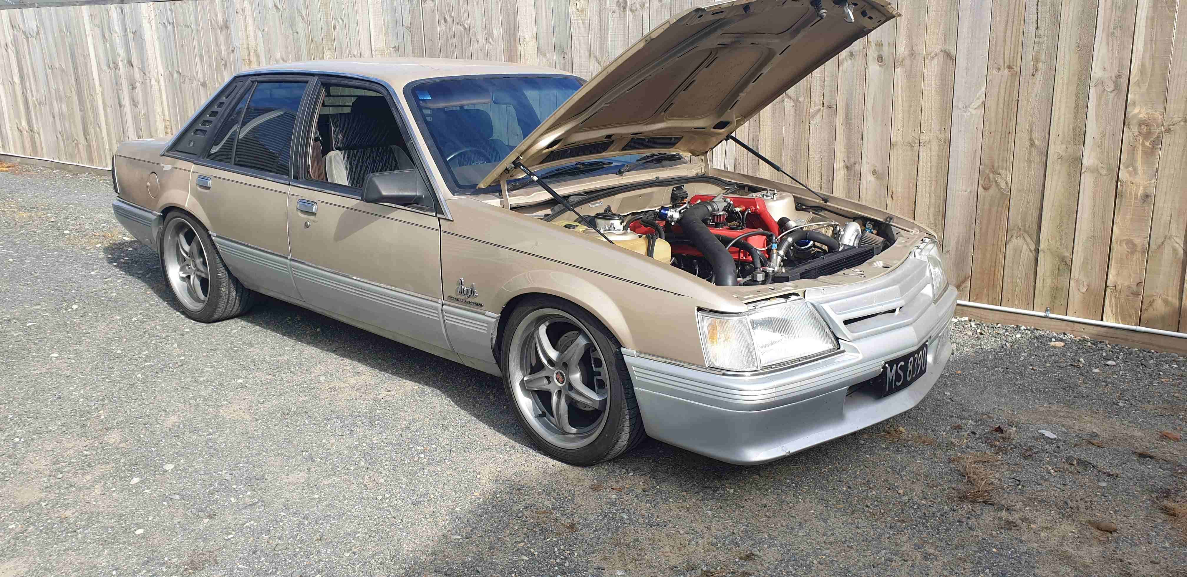
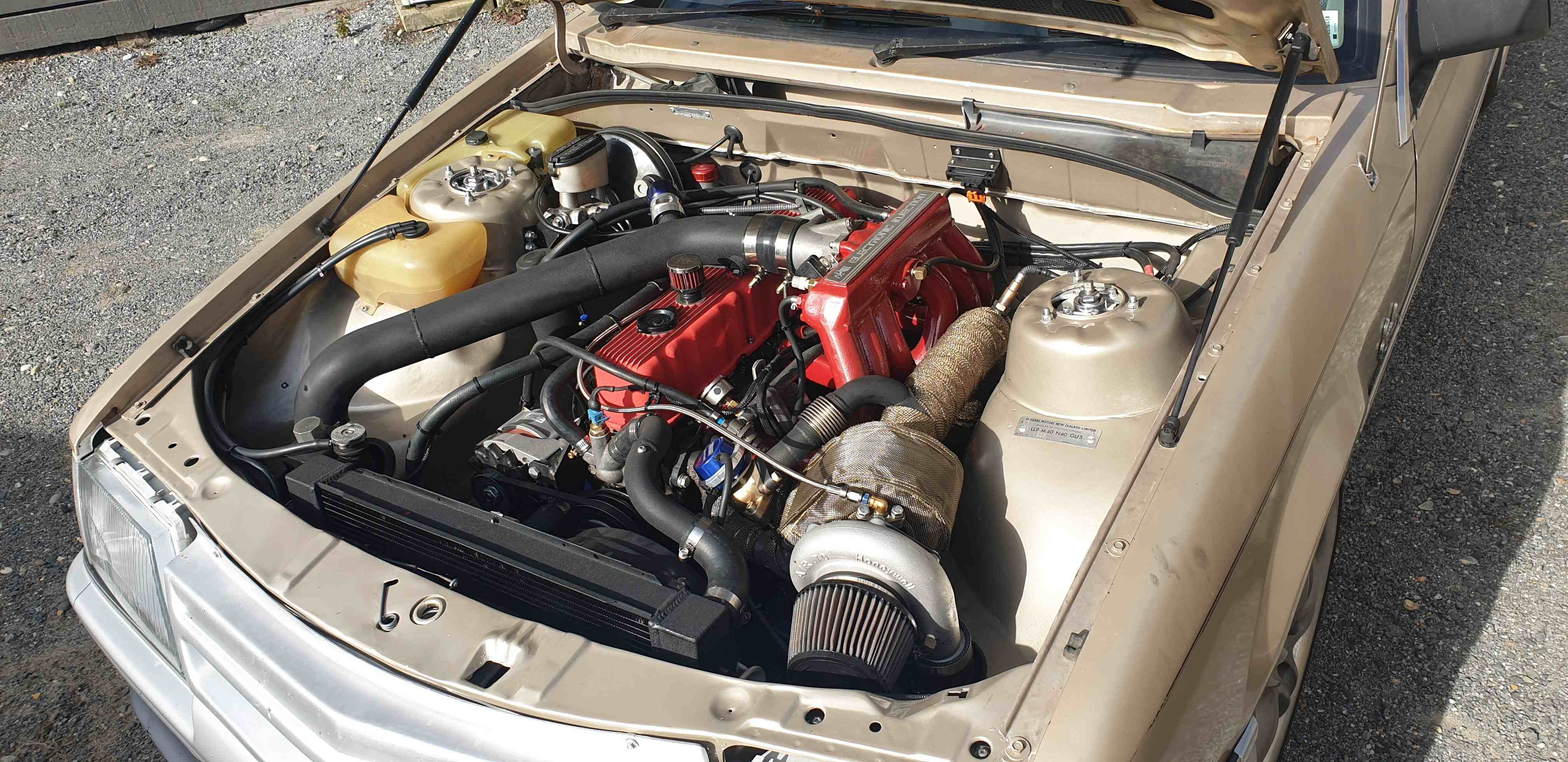
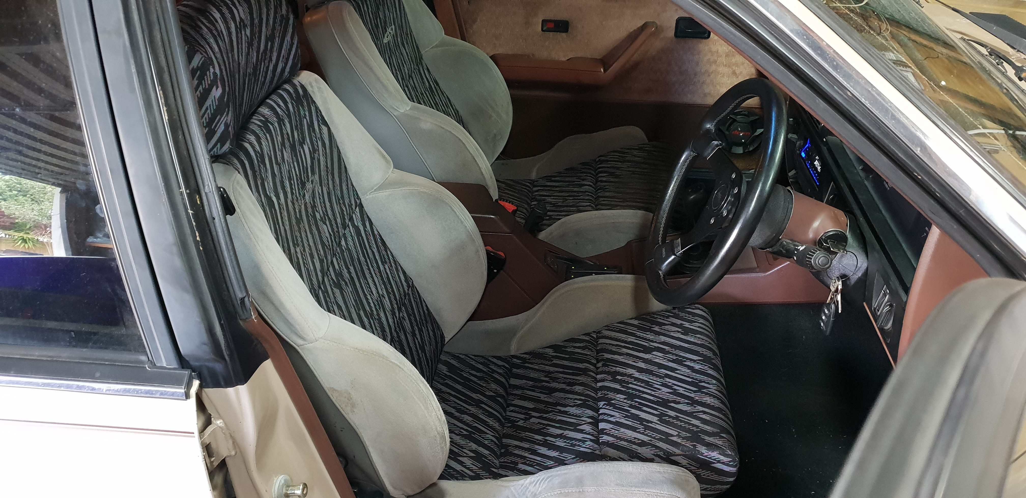
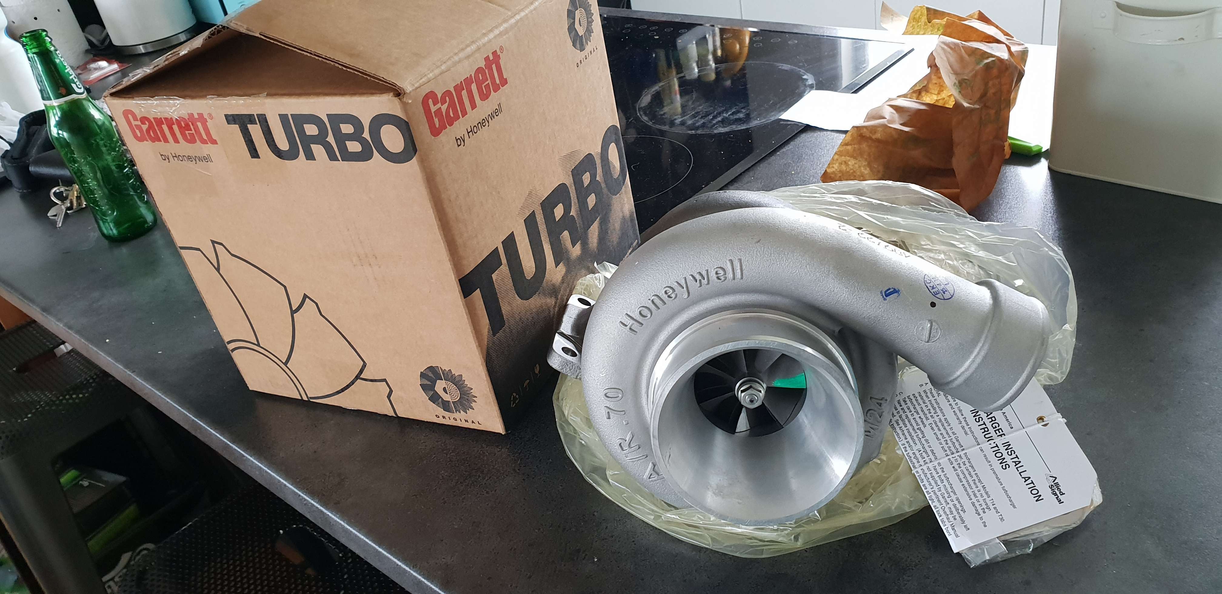
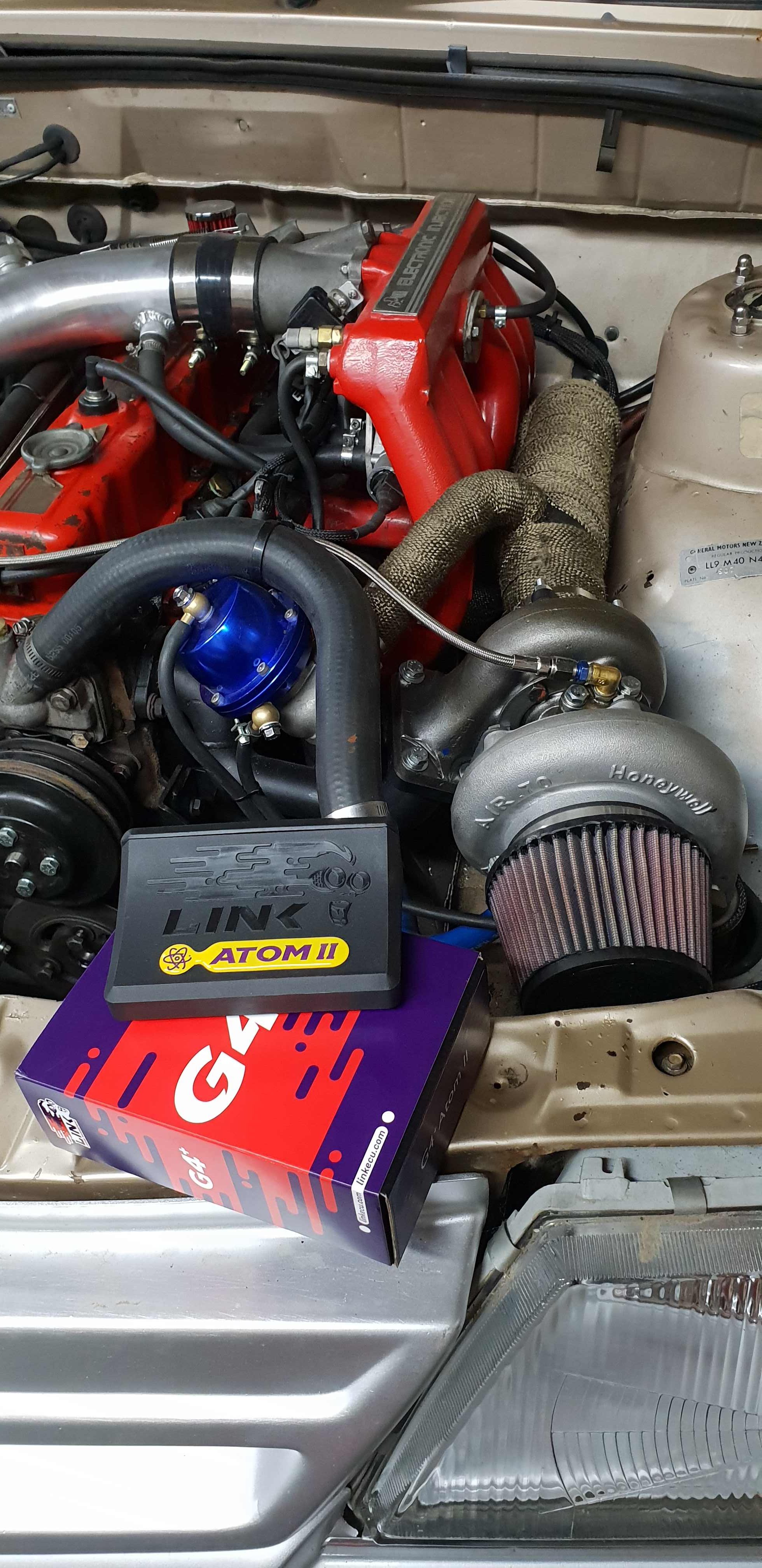
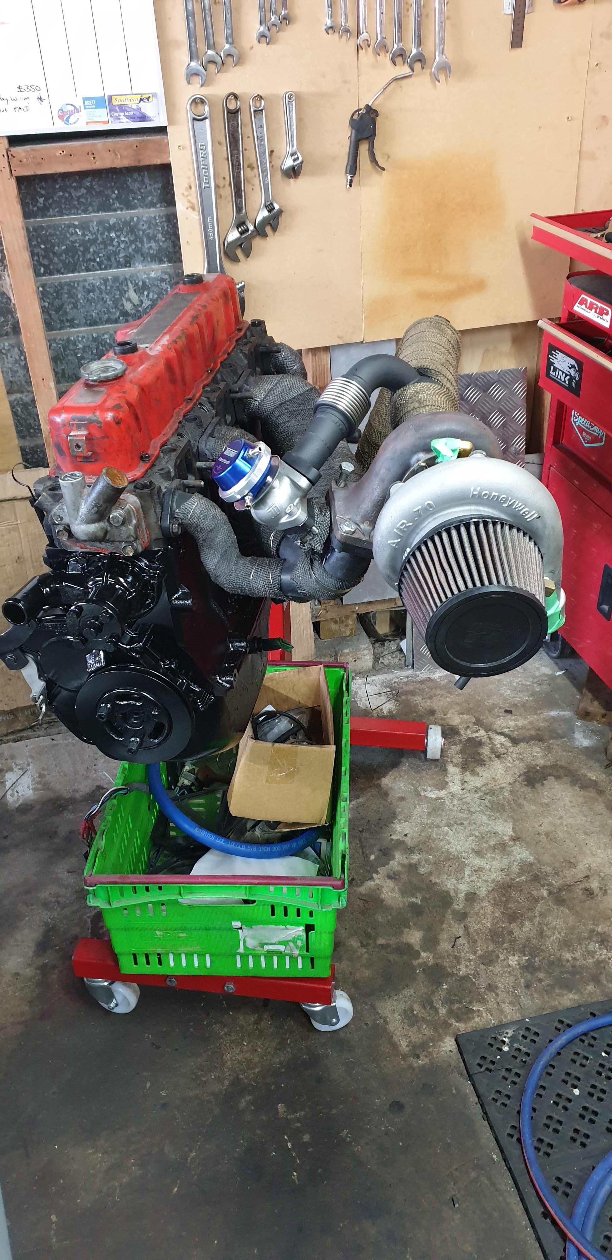
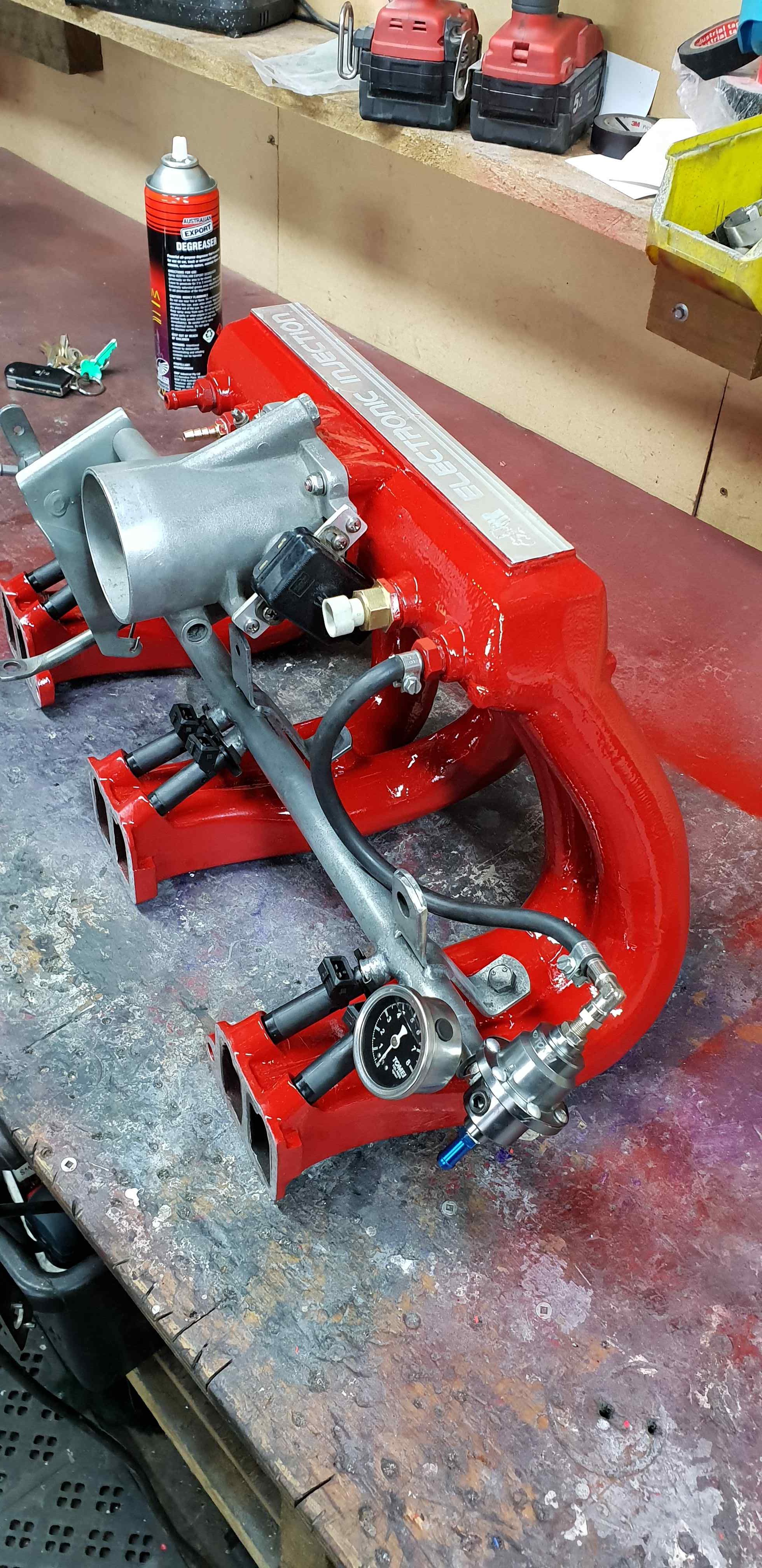
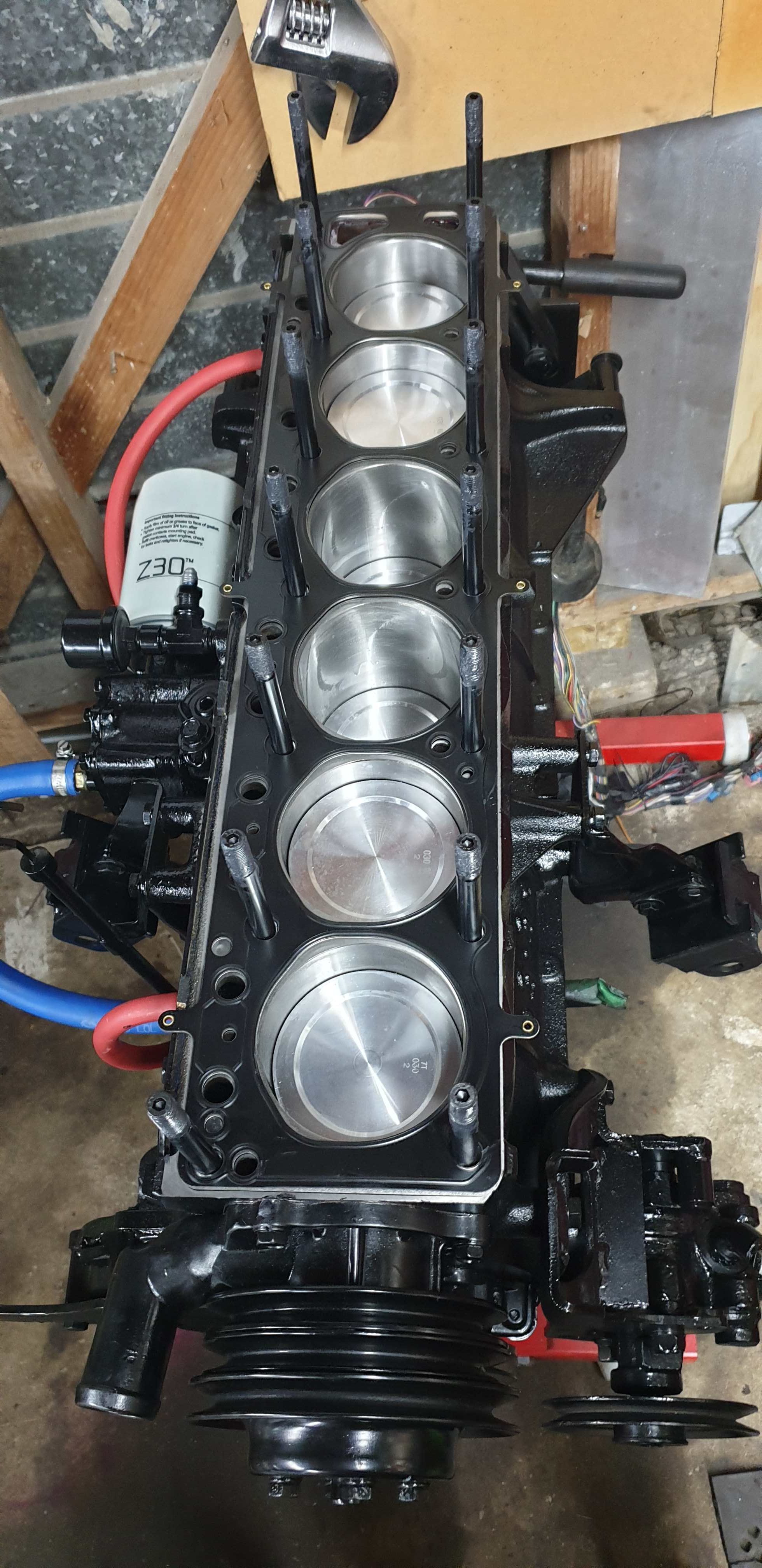
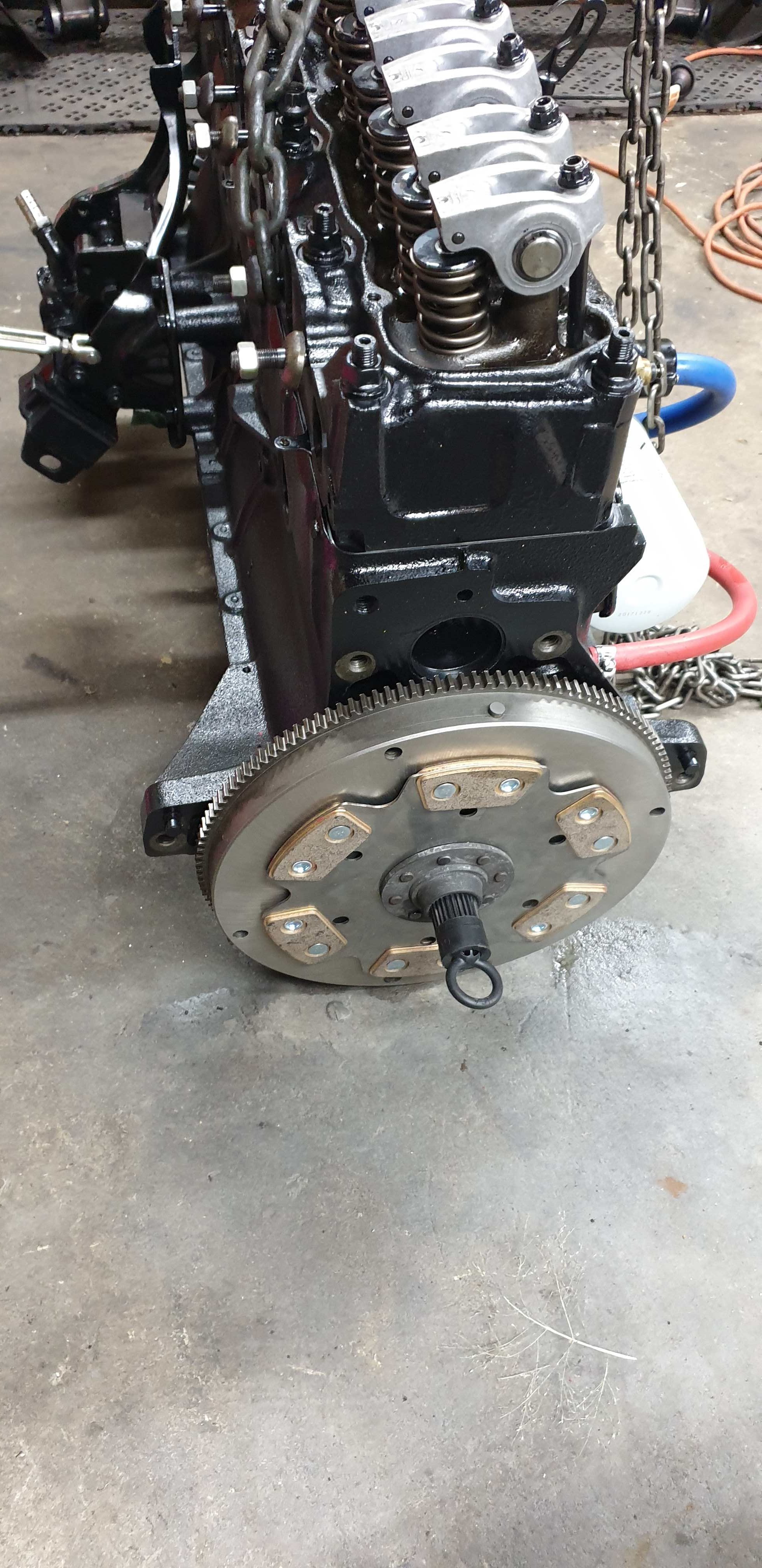
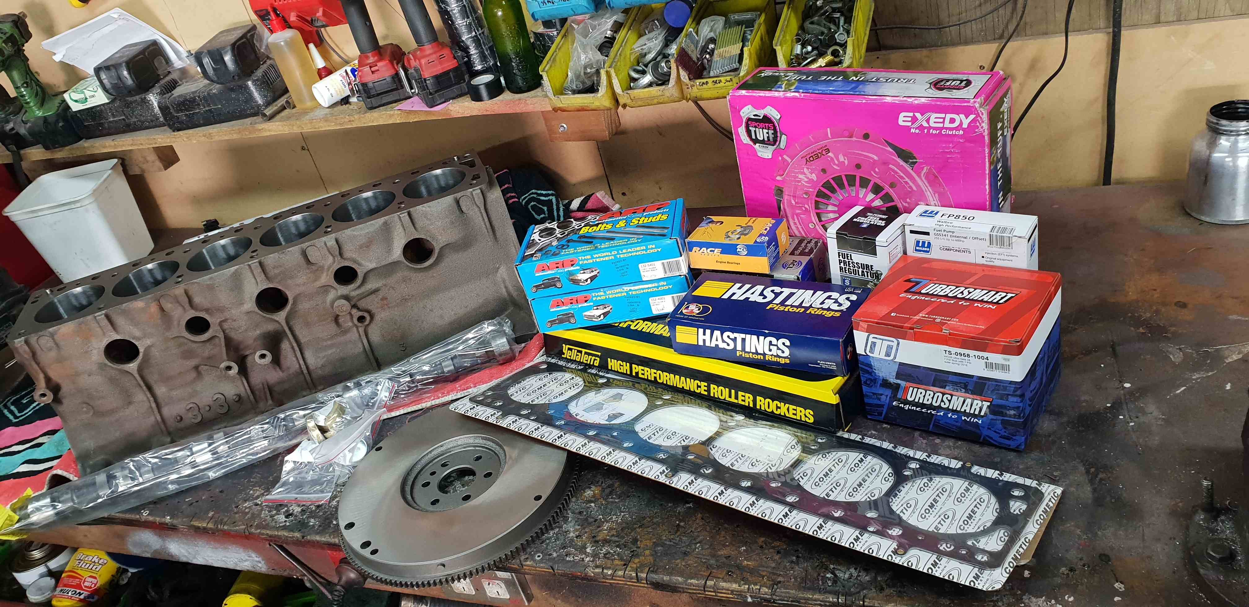
Since iv entered this thing in OS drags this year, its about time i chucked up a post about one of my latest money pits.... 1986 VK Royale (vk and a half efi 3.3) After a palmy swap meet road trip a couple of years ago in this VK my mate Chris offered me this... so it came home with me. I drove it for a while as is fixing a few issues and decided to sell off my other VK as a rolling body (kept the 327 for our HQ more in that some other time) also kept all the good bits for this one (suspension seats etc) then came the decision to do something different... and so it all started with a cheap second hand gt35 turbo off facebook (which turned out to be rooted) then came the Garrett turbo and the turbosmart bits and the link G4 and the gearbox, clutch, driveshaft and the full engine build.... and into the pit of $$ this car goes to save me rambling on Ill let the pictures do the talking.... also discuss here:
7 points
-
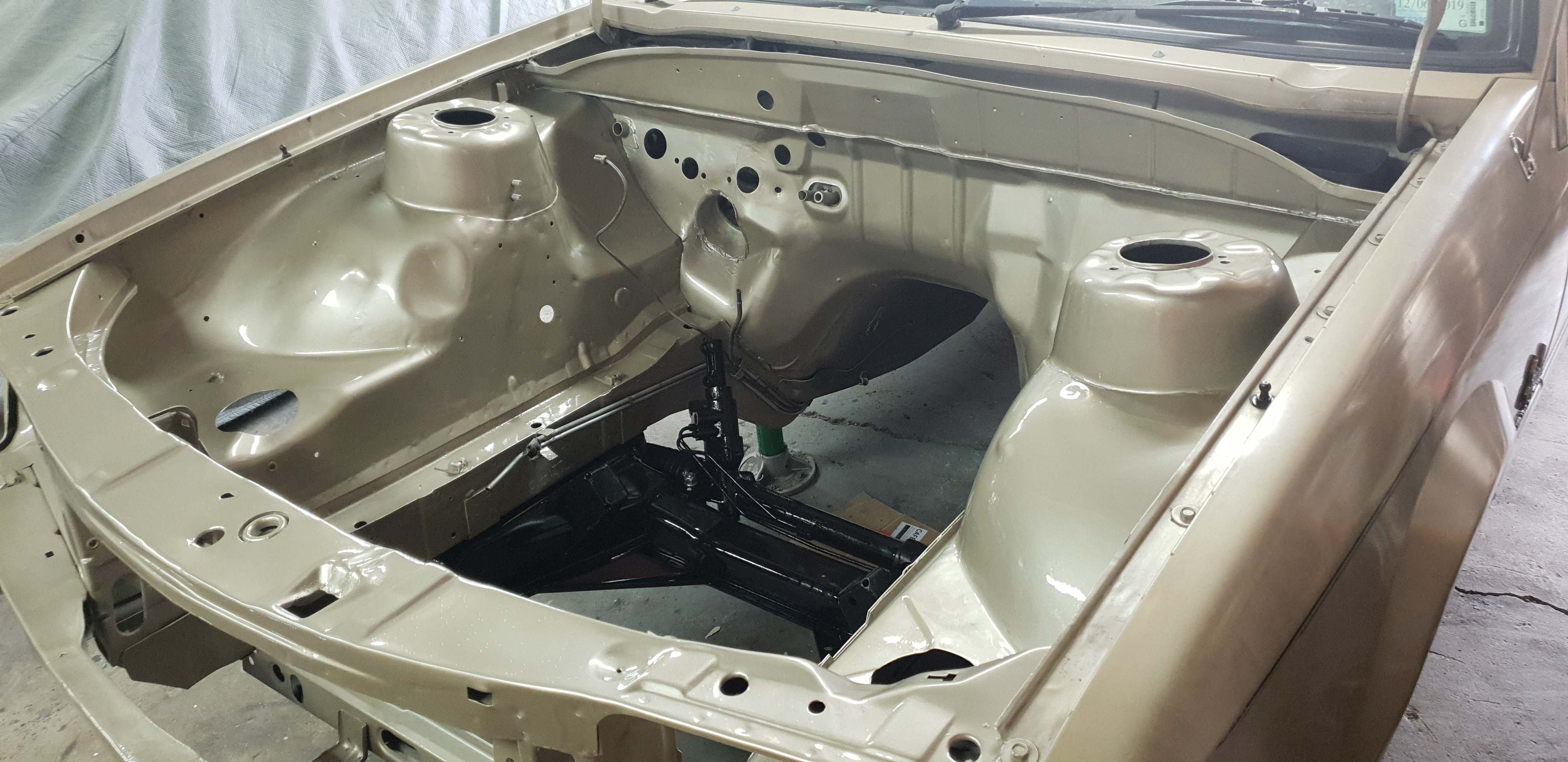
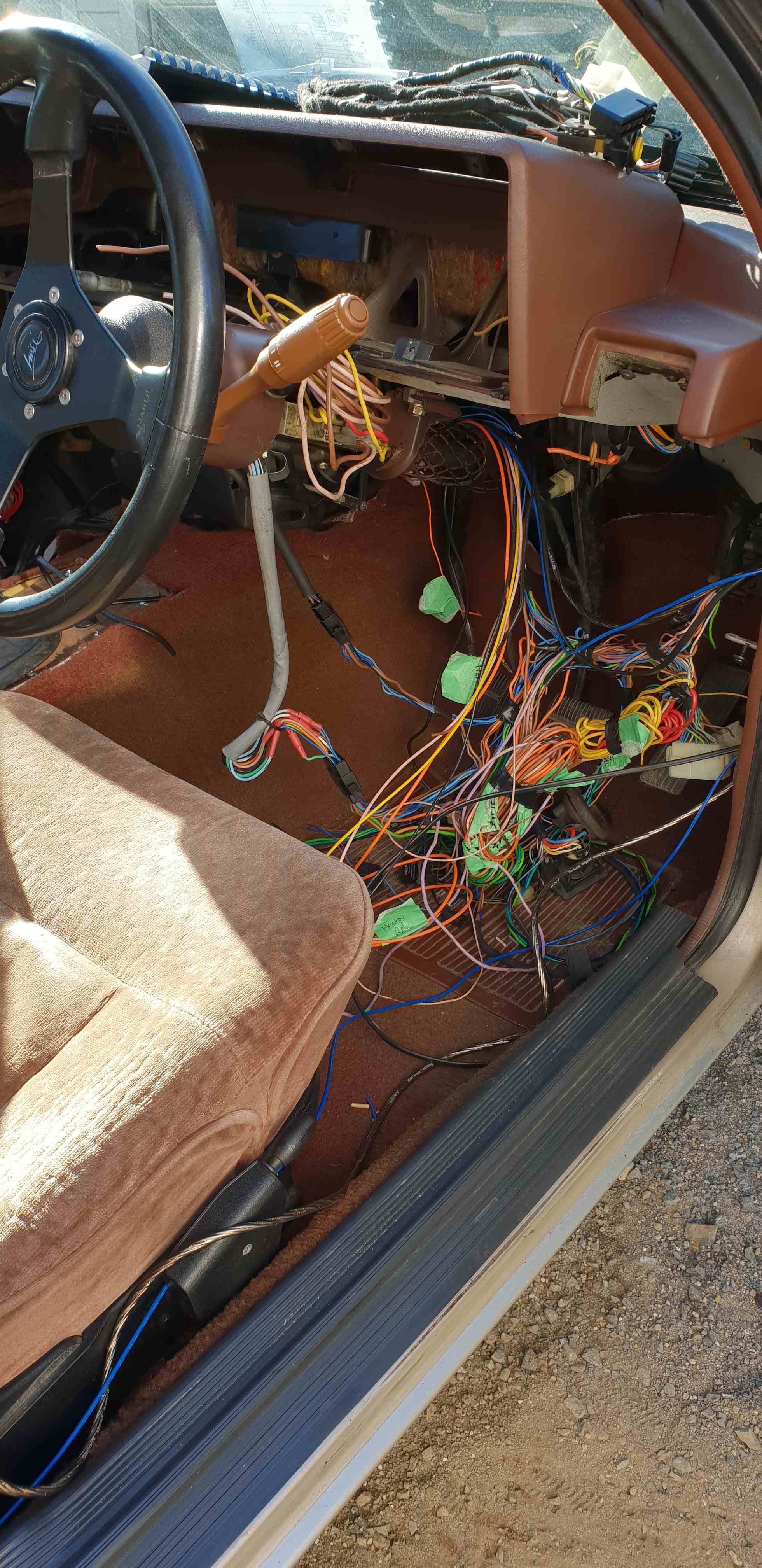
finally got a use for my VS HSV seats, painted the bay, and wired up the factory dash to be fully functional
6 points
-
had to move a bunch of wiring so rewired with an under dash fuse box , had the whole setup fitted to the old 270000k engine, made 168rwkw and 598nm of torque, annnd 3 days later blew the rear main seal coming back from kumeu in january. since then its been torn apart new rebuilt engine painted bay and a whole lot of other little things
6 points
-
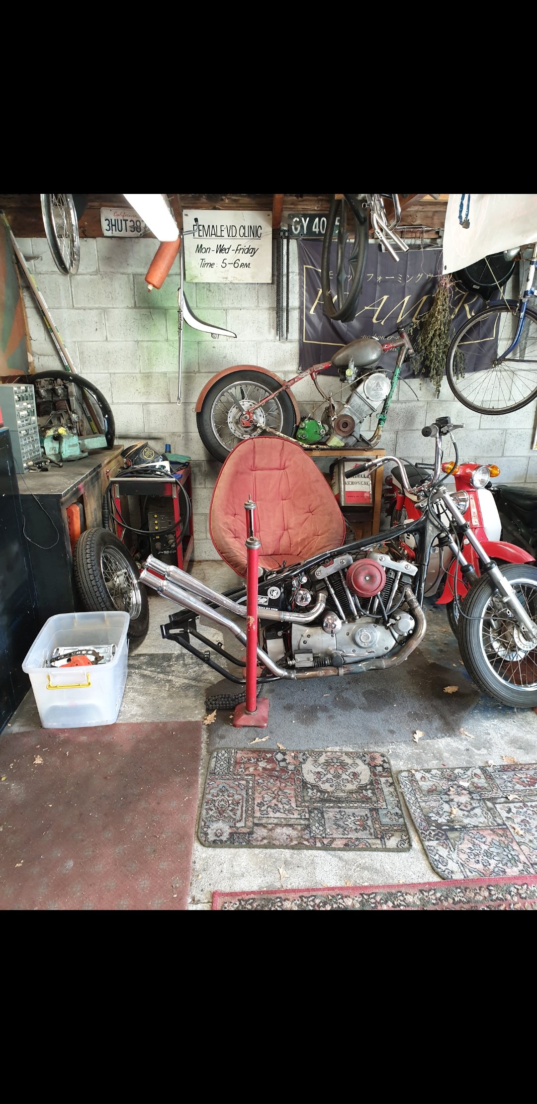
Had its first start last night, no dramas, just a couple small jobs now then it's time for first ride6 points
-
Long time no update, so pic dump Sissy bar/rack combo Fixing rusty tank Add screws and shake, weld holes, clean and seal6 points
-
engine cont.
5 points
-
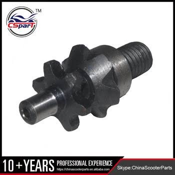
I chucked the new T8f sprocket in the lathe and took a 0.3mm skim off each side to bring it's thickness into spec. This was part of the deal when I ordered it. Here it is loosely mounted up. Luck of the Irish...everything clears where it needs too. Considering the first sprocket was almost half this size and that's what my design was tailored around - this was just dumb luck. But fuck it...I'll take dumb luck anyday, as I get my fair share of the opposite all to often. Ground clearance is tight, but it clears. I can put thicker sleeves on to raise it 10mm or so if this is really a problem? But think it'll work fine as is. Waiting on a chain breaker to arrive and then I'll sort the last steps out.
3 points
-
Stripped down to get some parts powdercoated. Then got fuel fitting to weld to tank and plumb up with new fuel filter. Then fit a couple plugs to the loom. Then final assembly with lots and lots of Nordlock washers & Loctite. Should Coincide nicely with this bike going classic on Jan 1st 2020 and I can actually afford to register it3 points
-
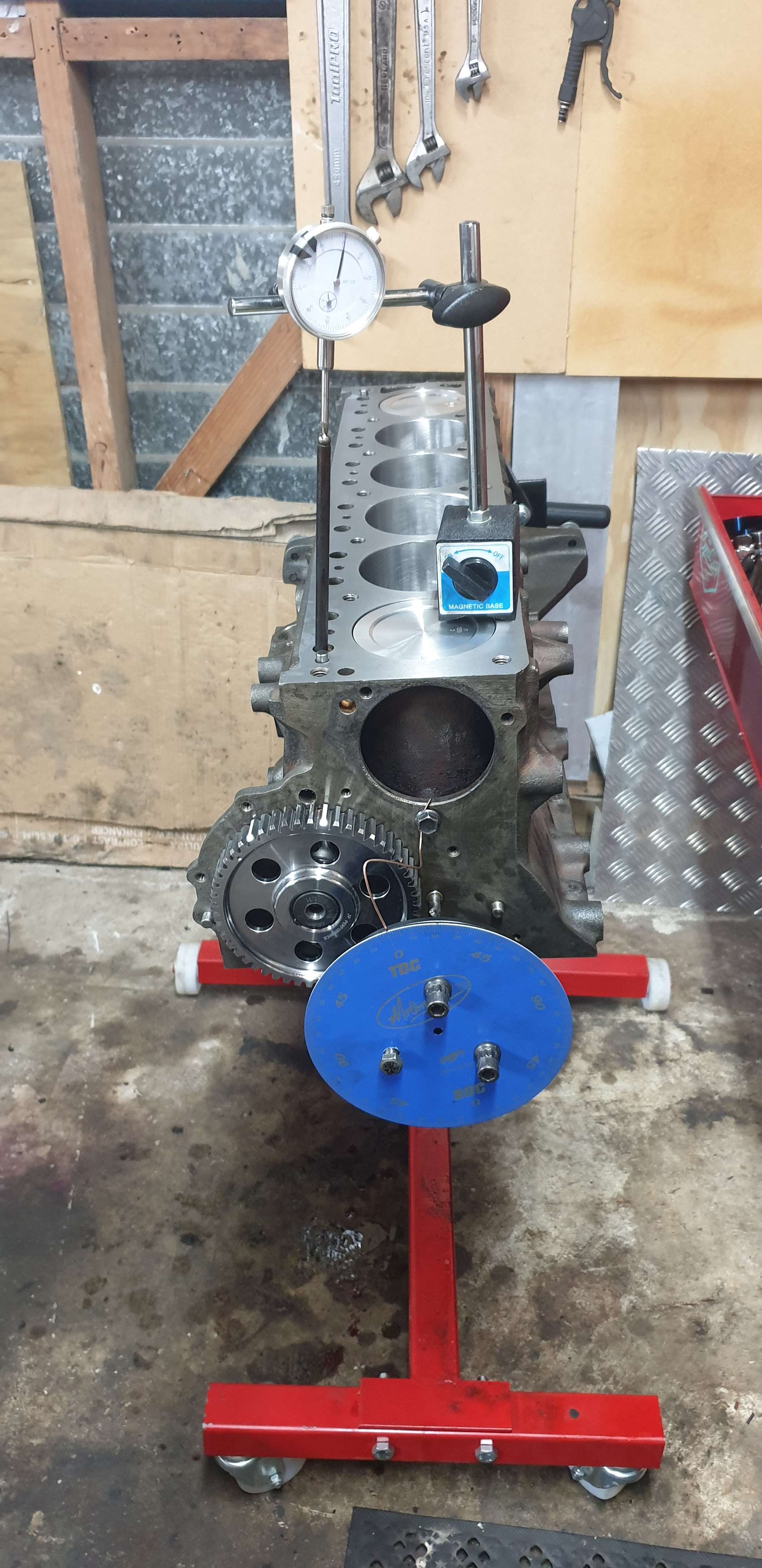
engine build
3 points
-
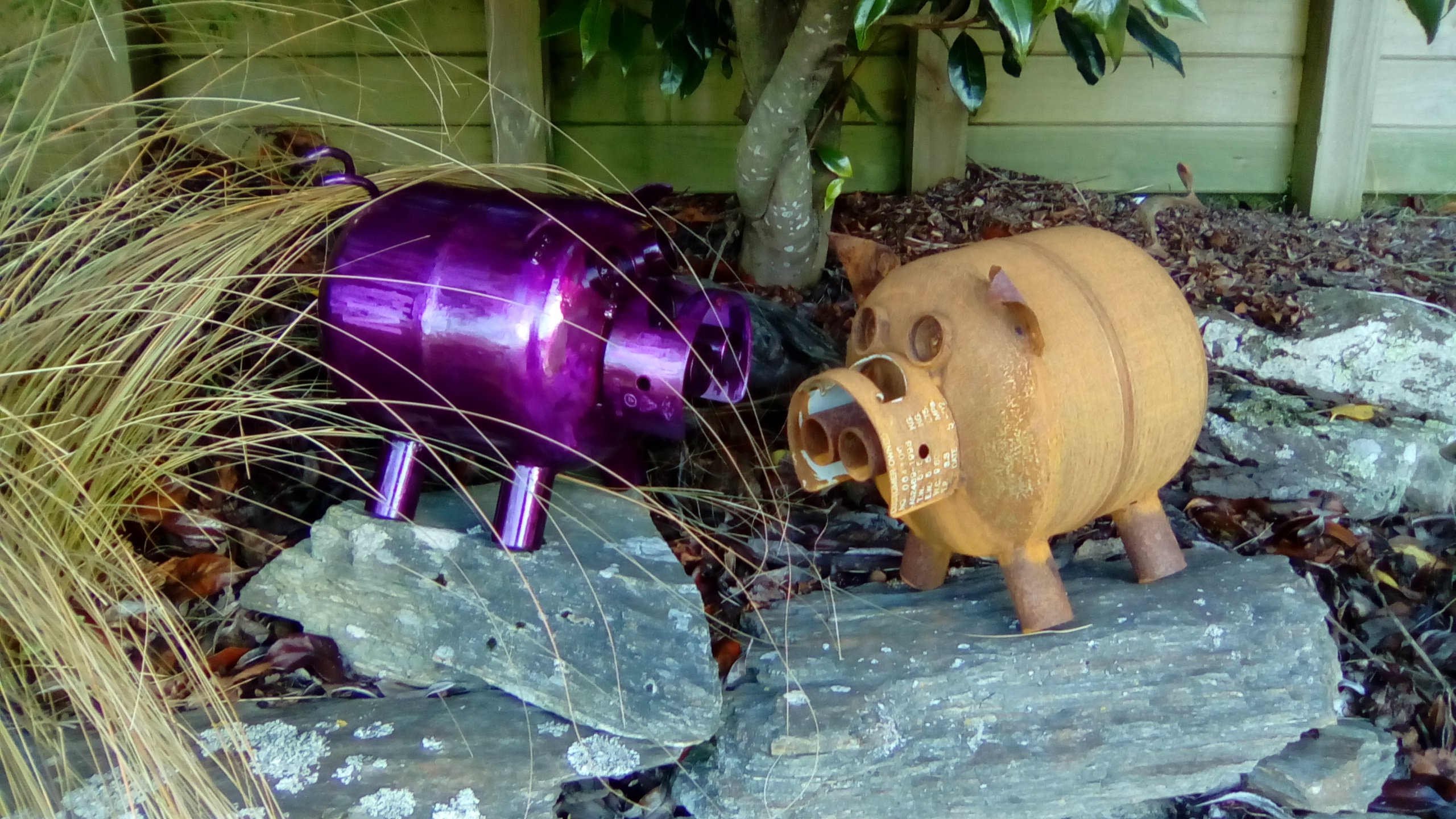
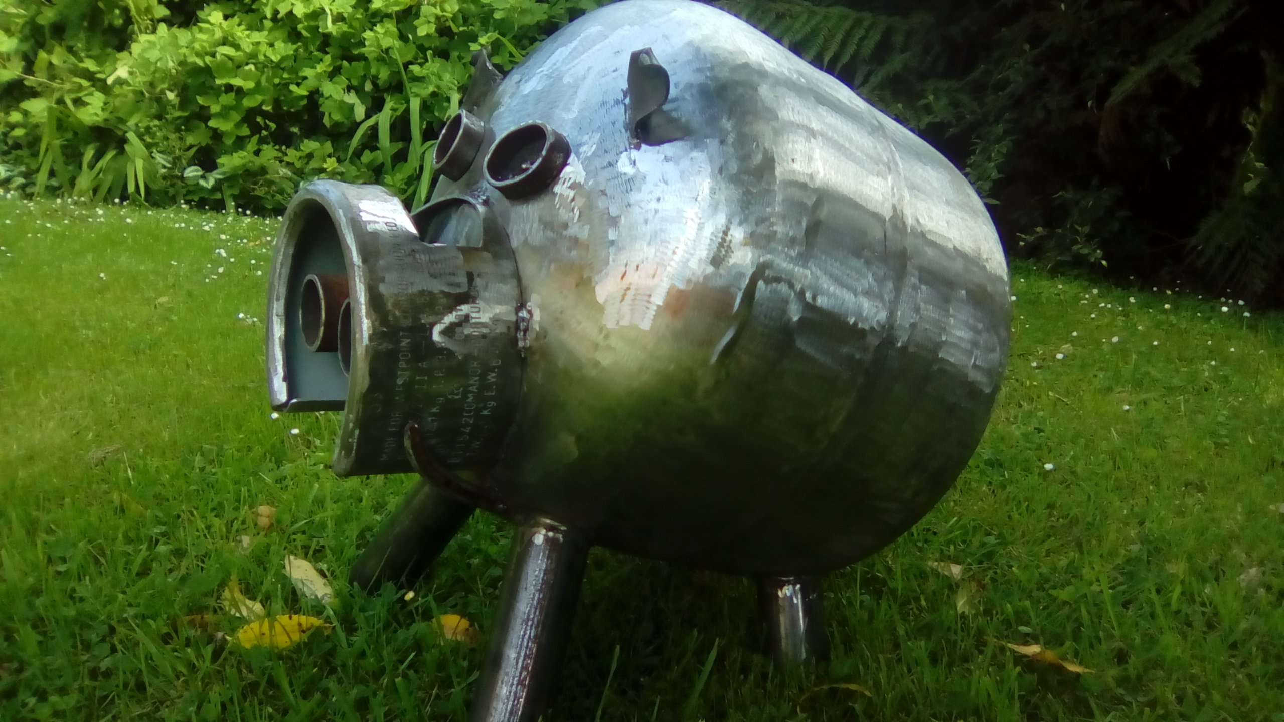
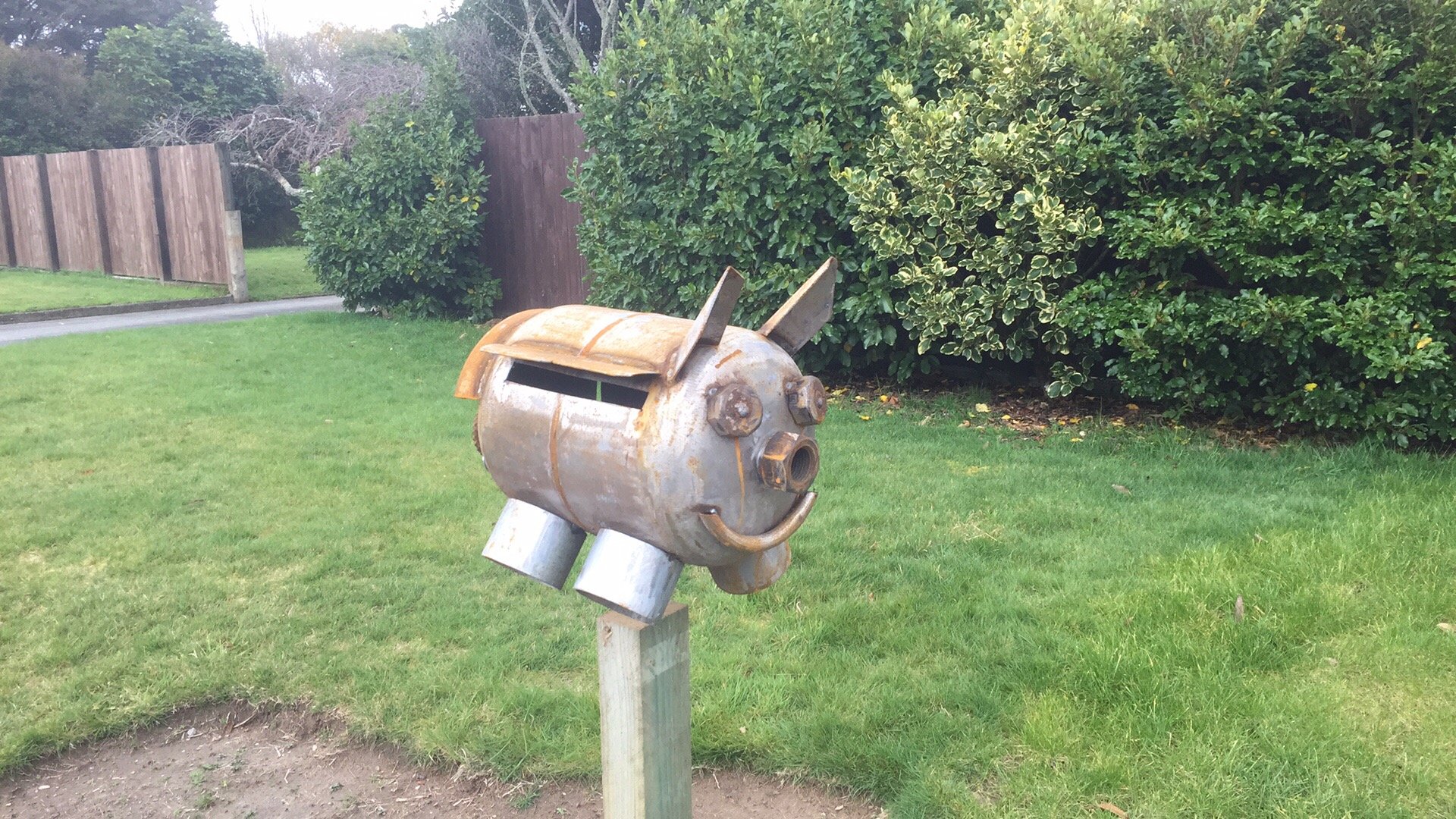
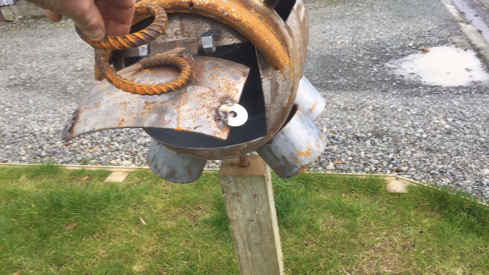
I just fill mine with water and leave them for a day. Empty them out and cut/ weld away. Some of my pigs. They are quite cool to watch as they weather. The rusty one took about 8 weeks to get a nice even coat.
3 points
-
But what if you want to make a backwards car?
2 points
-
I will be attending in a Mitsubishi Stigma yes, I will apologise now for the oil stains but thats they only way I know there's oil in it2 points
-
All in good time... But I think we can move on from this topic for now - I reckon it'll be legal with some minor modifications...2 points
-
Cert rules for lights. https://lvvta.org.nz/documents/standards/LVVTA_STD_Lighting_Equipment.pdf2 points
-
Here’s the rules https://vehicleinspection.nzta.govt.nz/virms/in-service-wof-and-cof/general/lighting/rearward-facing-position-lamps make up your own mind2 points
-
Since I'm still waiting on the pressure testing kit to arrive, I got impatient and did some more testing. I wanted to remove the injectors and see if any of them were leaking and what the spray pattern is. The intake plenum needs to come off. before this can be removed though, the coolant block on the front needs to be unbolted. Unbolting this saves disconnecting the coolant hoses. All the other hoses got removed, and the 7th injector was removed from the plenum. The plenum is held down with eight long bolts that go into the inlet manifold. Just a note, these bolts aren't sealed off from the inside of the plenum, so will need sealant on them upon reassembly. With everything disconnected and unbolted, the plenum just lifts off Removing the injectors is fairly simple. The clamp on the pipes (which goes above, below and between the pipes), as visible in the lower Lh corner of the above photo, has to be removed to allow enough slack in the pipes, but otherwise its a case of removing the single bolt per injector, and then pulling it free from the manifold. They are meant to be sealed in, but mine came out suspiciously easily. The rubber collar is weird. I presume/hope there is a normal O-Ring under it, as that is what all the parts manuals say it should have, and there seems to be no part for that rubber collar. I'll have to carefully remove and reuse the collar. All the injectors look pretty rough, but I guess thats what 39 years of sitting in the intake looks like. The ends all look clean enough, with no obvious buildup. I did note that cylinder 6 was very wet upon removal, and a couple of others were damp. The engine has been off and cold for about a week, with no pressure in the lines. Testing them isnt rocket surgery, just pop them all into jars, fire up the pump and see if they produce any fuel (which they all did to some degree), which indicates either the fuel plunger is letting excess fuel through, or the injectors are leaking. Further investigations show its probably a 50:50 on leaking or adjustment causing it. With the pump running, lift the sensor plate in the AFM to its stop and observe the flow and pattern from the injectors. All mine seem to flow roughly the same, but the flow pattern out of all of them appeared to be rubbish, with minimal misting and heading off in all directions. That's good, it confirms that buying a whole set of replacement injectors was the right decision! One other thing that has been bugging me, was the sensor plate in the AFM. This is meant to be a finely calibrated instrument, but I think someone has mucked with mine before. You can see in the above photo that it looks like the sensor plate (the disk in the middle of the cone) is sitting high with a gap under it. Well, it is. From the below diagram, you can see the sensor plate sits at the bottom of a cone. As air comes in from the filter at the bottom, it comes in under the plate and a combination of that air coming in, and engine vacuum in the intake, lifts the plate to allow air into the intake. Lifting the plate also lifts the fuel plunger, increasing fuel flow. The plate should be set to a specific height, which is more or less with the highest point of the plate flush with the lip at the bottom of the cone (before where it tapers outwards again, under the plate). Mine was clearly sitting a lot higher than that. Not to mention the other issue... The plate was off-centre. I even thought the plate was too big to fit through the opening, but it was just because it was off-centre. I carefully backed off the center bolt, and centered the plate (this should be done with feeler gauges, but I did it by eye this time) Now it fits through the opening It was still sitting too high though There is a spring under the plate that sets the height. The manual says to adjust it with pliers, but I'm damned if I can bend the thing. I'll keep at it and see if I can tweak it. The other thing I noticed is that you can hear and feel the plunger moving when you manipulate the sensor plate. I'm not sure how normal it is, but my plunger seems very slow to return to the zero position. It doesn't seem to bind and it moves smoothly, it's just slow to return. I'll be removing and cleaning this in the future anyway. So that's where I'm at. I'm waiting for a set of new injectors to arrive, and I need to remove the fuel distributor and WUR to clean them out. I'm planning on setting everything up from zero since I have no idea what's been done to this by previous bodgers.2 points
-
Success! The 1G SOHC crankshaft and connecting rods have, and will work perfectly in my twin cam block. Need to find time to get my block sent away to dipping. I'll be taking the head in to get refreshed sometime next week, I've had it quoted up. I'm currently waiting on the cheap and probably shit really good value complete gasket set from Aliexpress. Cringe all you like, I've heard good things and it includes every gasket + seal required On the body side of things, I really need to get into the rust spots that are forming under the paint. I'm expecting some lovely filler work when I go digging rust out, shes had a repaint at some point in the past. Hopefully it doesn't become a huge nightmare and I can keep repairs small and neat. The bonnet has rusted out on the inside, but I have a basically new, perfect bonnet that needs to be painted and put on someday. It would be really neat to have the stickers in the engine bay and under the bonnet reproduced so I can put them on after the engine bay gets it's respray. As far as ride height etc goes this is awful to ride in. If it weren't for the comfy seats I'd be seeing a physiotherapist by this point. The rear springs have had some meat removed and it has really short and stiff Mitsubishi springs to keep everything tight but it jumps over bumps, bounces over every little thing in the road. Suspension + springs etc is certainly not my strong point so any advice on making it a little comfier to ride around in would be awesome. I thought X73 king springs may be the solution, but I'm not sure they'll fit. I had even brainstormed the idea of fitting the IRS rear end but really haven't put thought into that. I don't really have the coin for S13 front coilovers at this point in time. That's all for now, I'll update the thread when I rip into it and start changing things (again). Grabbed some pics out on a weekend cruise.2 points
-
My boy loves checking the mail box every day so I surprised him with this. he thinks the coolest part it taking letters out of the arse. should rust up good.
2 points
-
1 point
-
If he's in cause he's in, then I'm in.1 point
-
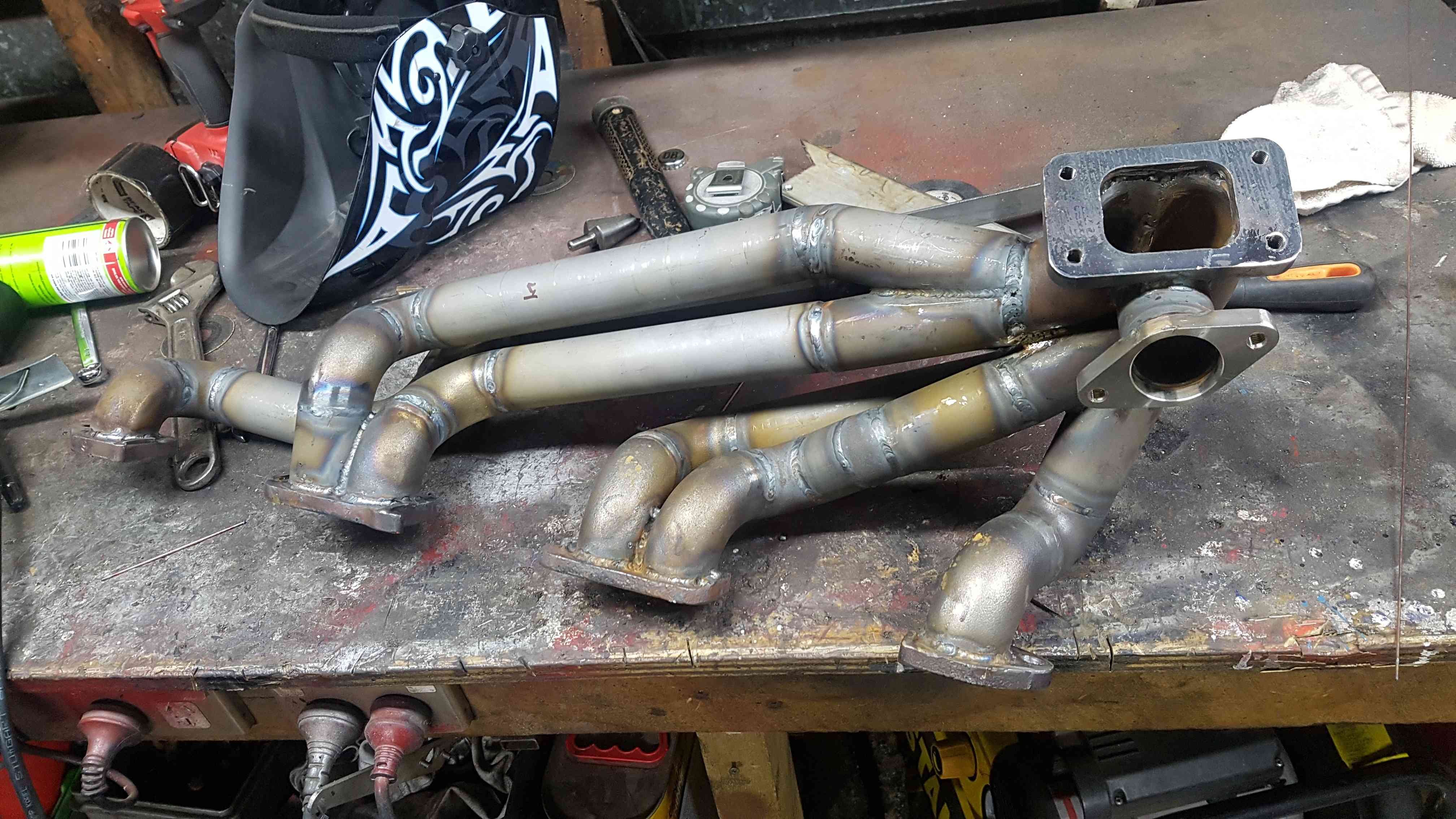
Sure goes alot better than it used to, lots of $$ add up fast tho doing an engine thats not commonly boosted Turbos A TA3410 (t3/t4) AR 0.70 compressor and 0.48 turbine housing, spools up nice and fast1 point
-
Damn this warms my heart to see a wild looking cub in the build and to know its being built with good mates surrounding each other and helping each other out. Stoked its running now mate !1 point
-
Yeah aftermarket ecu required for mpi. I would put factory manifold back on (make sure injectors don't leak) fit an tc05 exhaust to the 06 front housing and boost it up until it won't let you go any higher, on mine around 14psi. Then if further modifications are required go to mpi, vr4 pistons and modern turbo.1 point
-
Headlights for taillights? Please post pics in the design fails and fabrication foibles thread1 point
-
I have no idea what ur making but looks cool1 point
-
Headlight for tails would be great! And use the high beams for the stop lights. #tailgatersgetfucked.........1 point
-
If he’s in, then I’m in.1 point
-
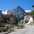
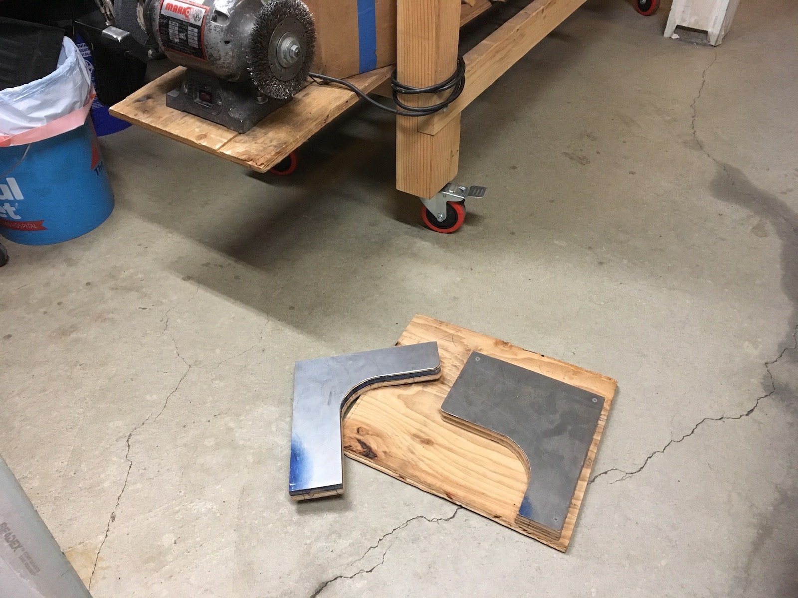
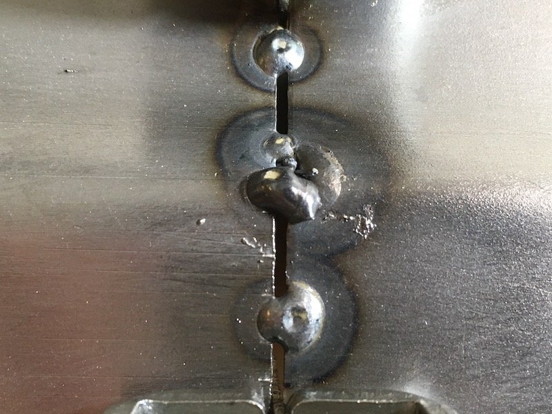
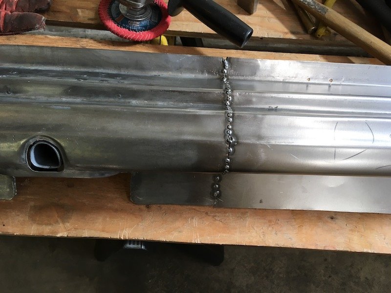
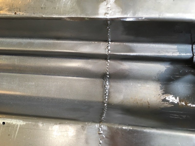
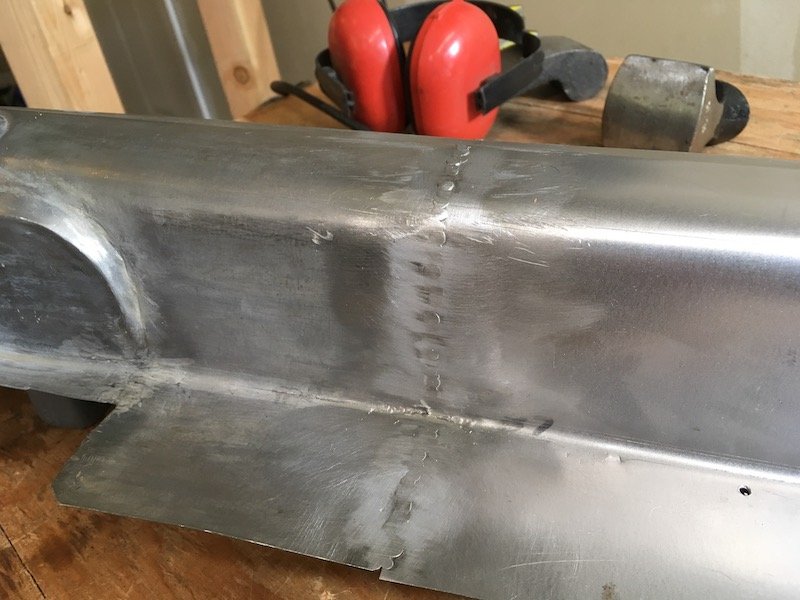
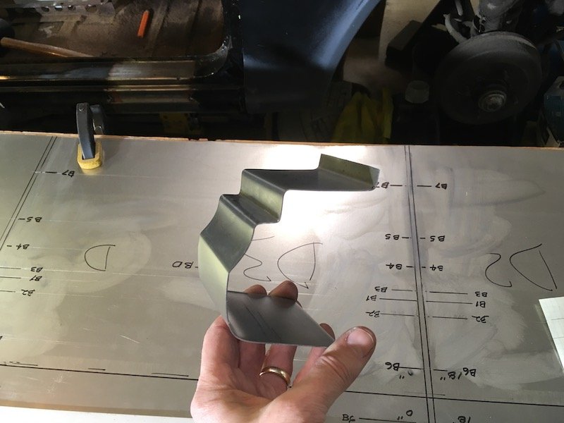
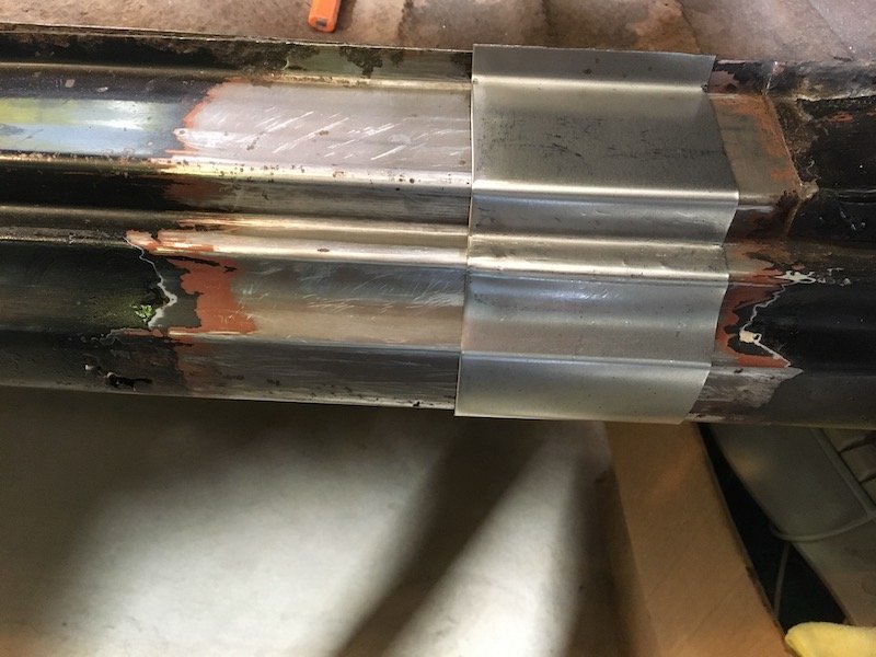
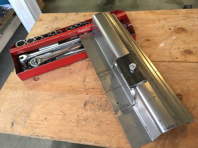
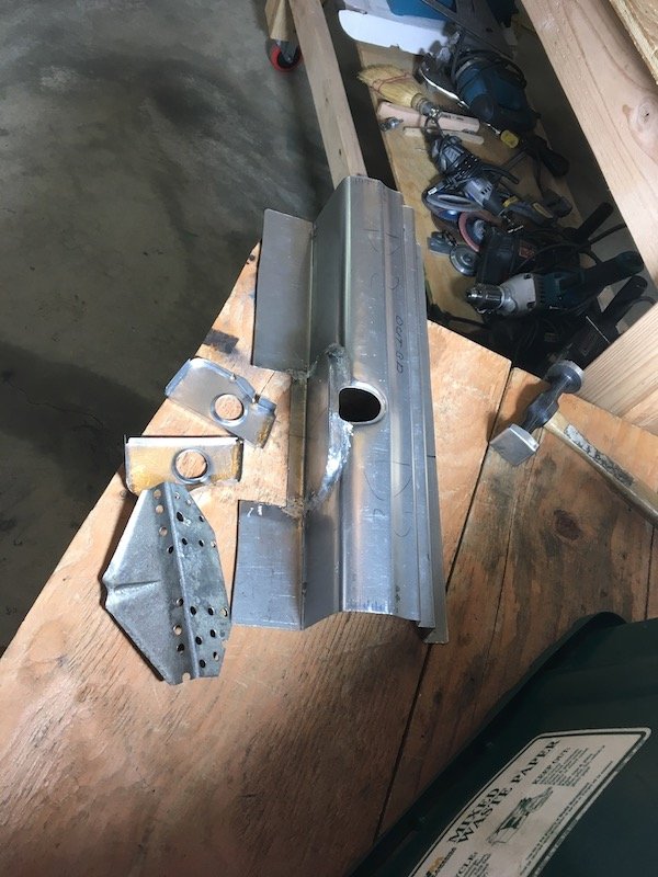
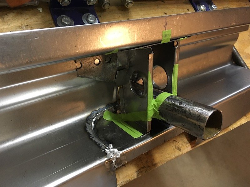
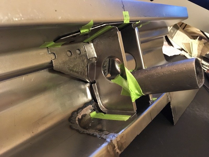
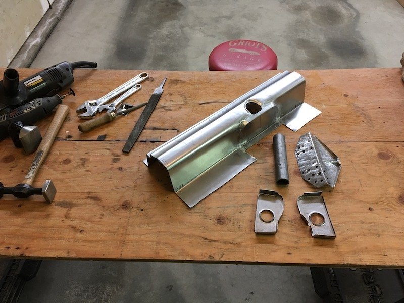
@tortron Thanks for the suggestion. I've been working on dies intermittently last couple of weeks. So far made something like this. Only part way there. Need to figure out a way to guide them together during the form operation and prevent lateral spread. More on the dies later, I've been slowed down somewhat by making a bunch of replacement underfloor supporting brackets out of heavy 16 and 18 gauge sheet. One example. Two separate bent up pieces. Then butt welded down the middle
1 point
-
Resurrection Session 1: Missing sparks in cylinder number 6. Diagnosis = bad lead. Researched and found that VL Commodore RB motors have the right length. Not perfect, but close enough. Found bargain. Purchased. Fitted. Next went for a drive to diagnose further problems. Broke down. Pulled fuel line off crab and noted no fuel coming through. Luckily a strong and powerful rescue car turned up to help with a Jerry can that was rigged direct to the carburetor to return home. This worked fine until the Jerry can ran out. Ran the last 200 metres on brake-kleen sprayed directly into the carb whilst perched on the guard. Diagnosed fuel blockage in tank and now dead electric pump. Cleaned out tank and gave it a paint. Will now try sourcing a new pump and nylon lines.1 point
-
1 point
-
Yes, I swapped the gearbox as well. I put a wide block turbo motor and box into a ute that was narrow block non turbo. The turbo motor and box was a hydraulic clutch where as the ute was cable. Have you tried to fit the driveshaft to your turbo gearbox? Sometimes it can be a bit of an optical illusion, there is a good chance that you can dismantle the drive shaft cross and fit a turbo yoke onto your drive shaft. Failing that you'll need to get a custom driveshaft made up.1 point
-
Just as a quick follow up. I have ordered a set of new injectors, and will be removing the fuel distributor to inspect/clean the plunger. I'll be setting it up properly from a zero setting after cleaning everything. Just waiting on parts/tools to arrive. I've noticed the AFM sensor plate is way out of setting (should be sitting a lot lower than it is) so either its sticking or its been setup incorrectly (50:50 on either). Chances are the system was running a bit average due to a lack of maintenance, so it was "tweaked" to compensate and now its all out of whack, seems pretty common for people taking on projects with KJet.1 point
-
How it should have always been. The pedal set fits great. I'll need to cut the hole in the firewall for the master cylinder but that's the extent of it it. Seeing three pedals makes me very excited for the future of this car.
1 point
-
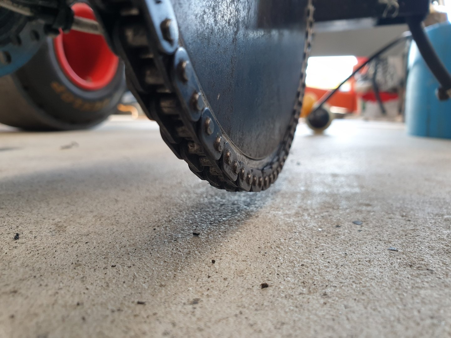
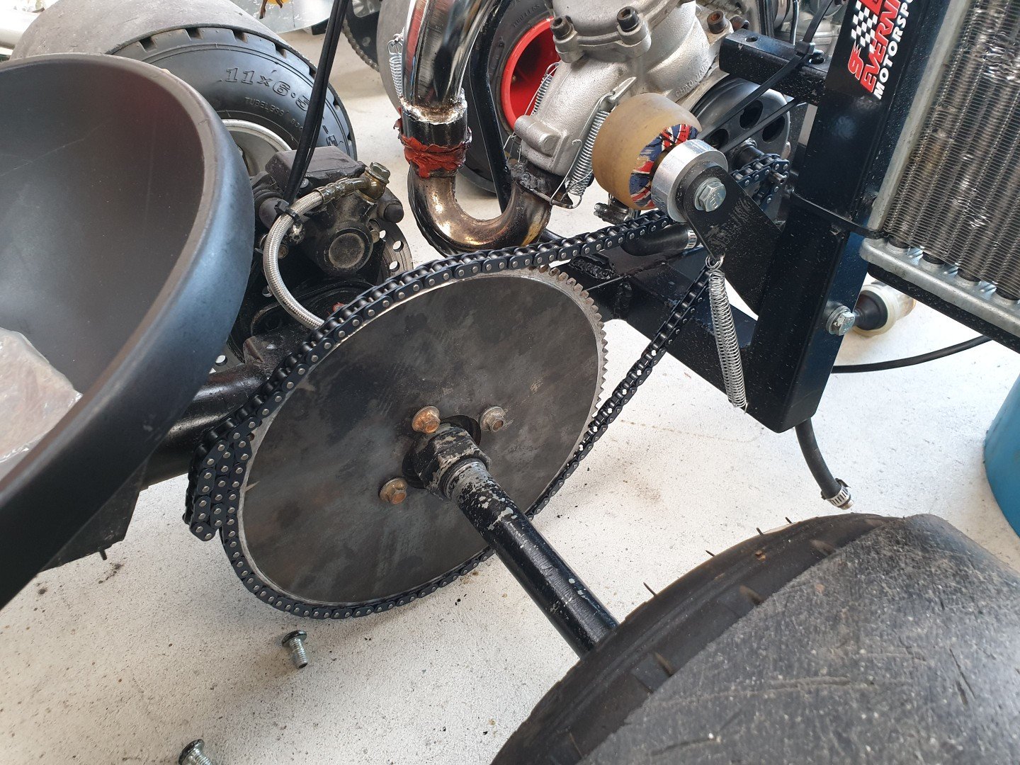
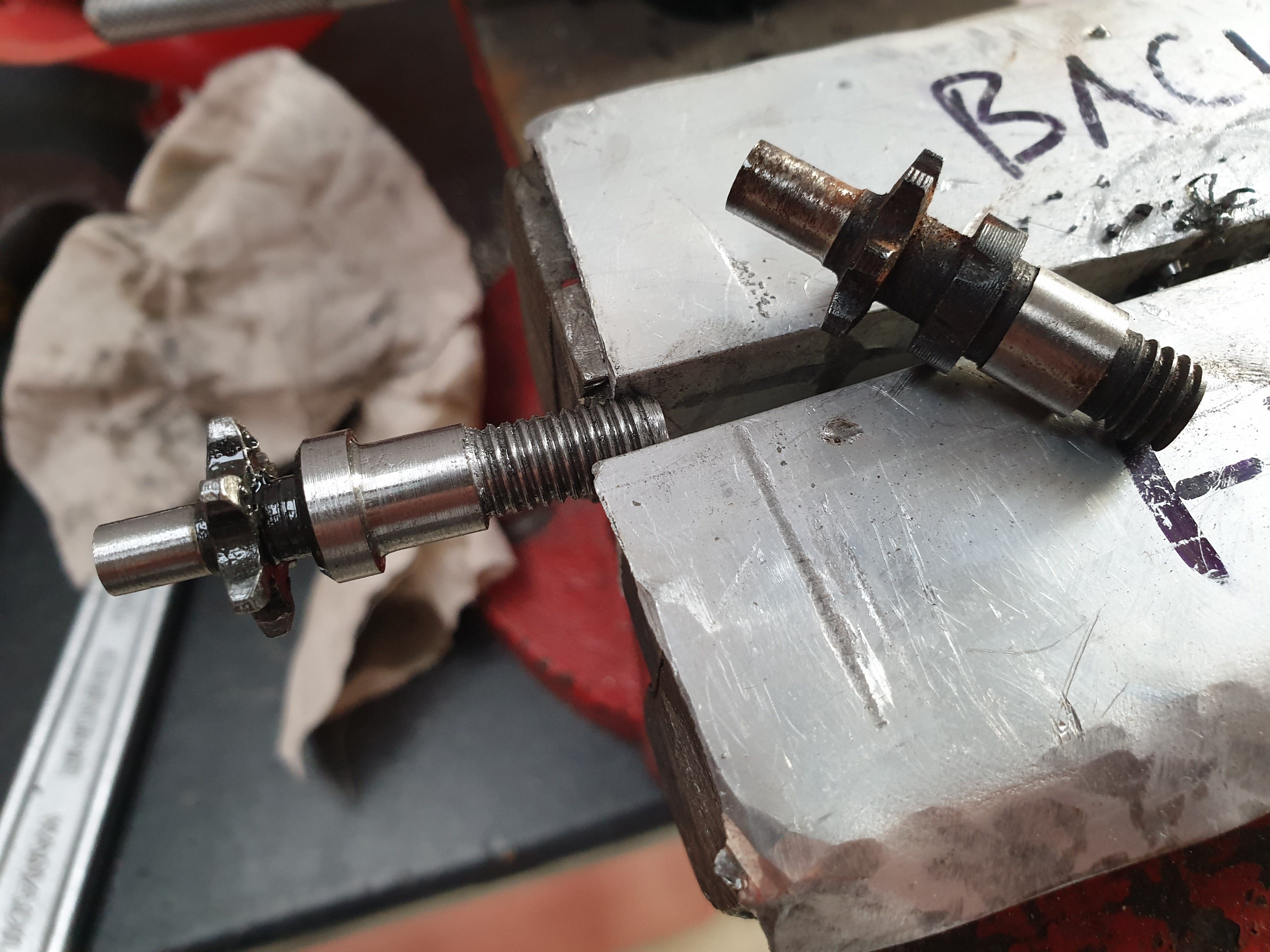
So, this motor just destroys chains! I was running a tiny pocket bike chain in 25h pitch. This works with a pocket bike, but not so good on this drift trike. I think my gearing ratio and extra effort it takes to turn the big rear axle adds a heap more demand for the drive chain. So @anglia4 sorted a new rear sprocket by water jet cutting it. I've upgraded it to a much larger size to reduce the load demand from a standing start. I've been away all week, but reception called me to say a few things arrived at my work (this being on of them). So looking forward to collecting it tomorrow. Meanwhile in anticipation, a spent an hour tonight making this: The one in the vice is the one I made. You cant buy these in T8f chain pitch, so I made one out of a 49cc mini mx bike part. This is what I started with. It required a fair bit of turning on the lathe to make it, taking it down from M10 to M8 and machining a collar to fit in the new clutch bell etc...but luckily for me, all the sizes required were smaller than the original part started out at.
1 point
-
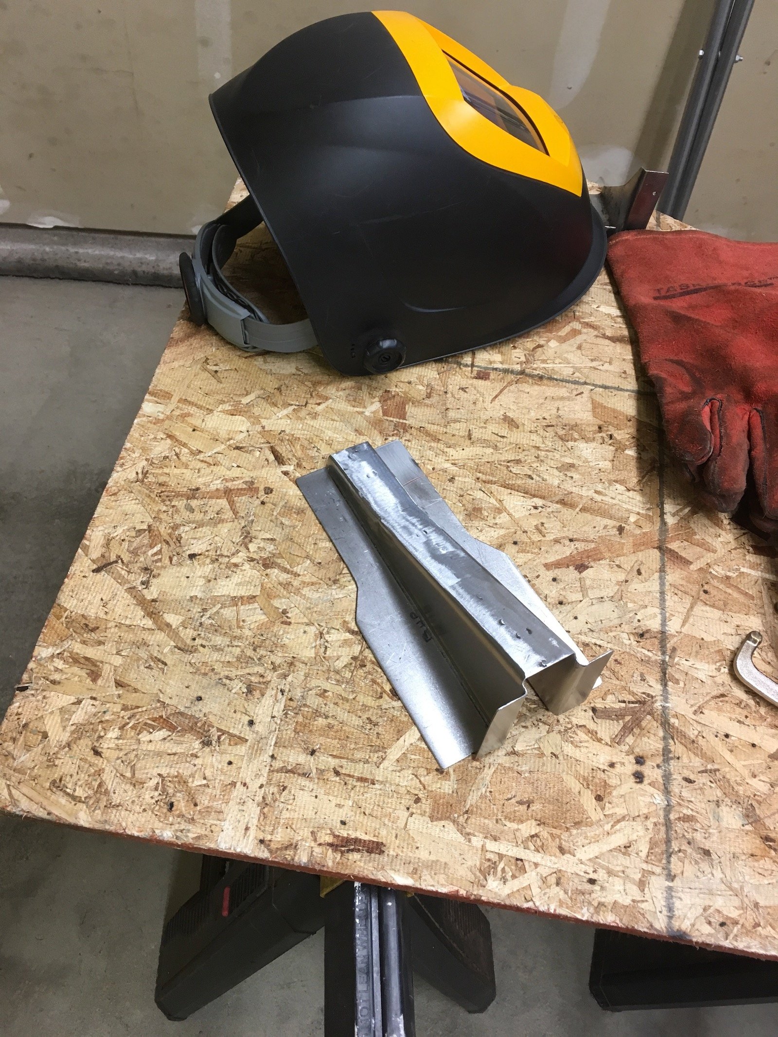
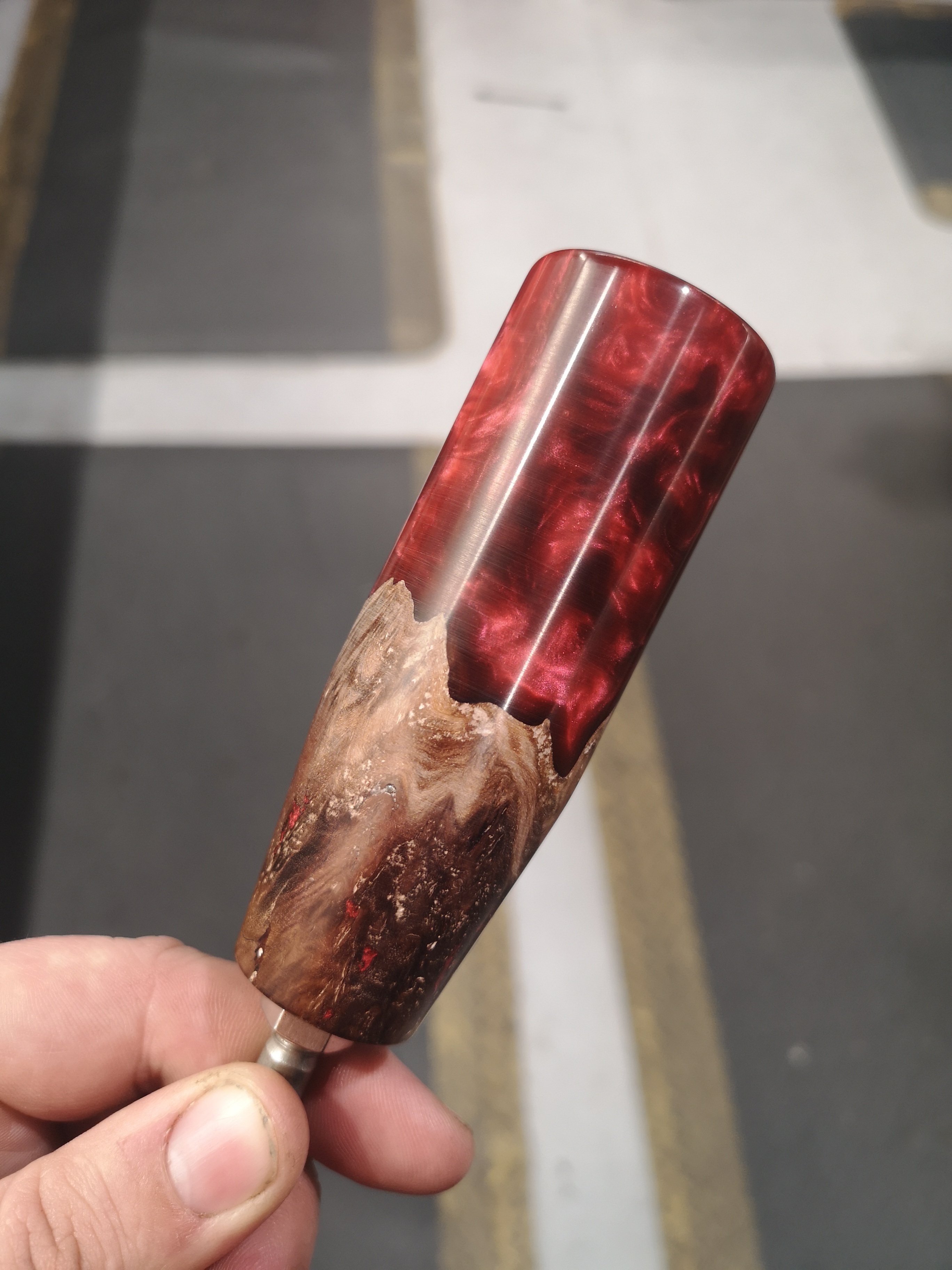
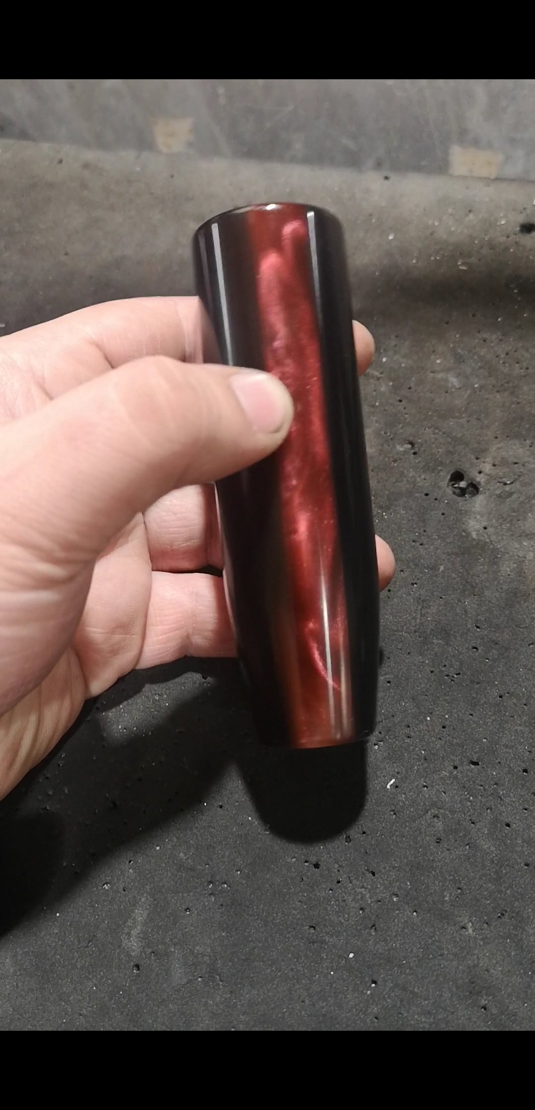
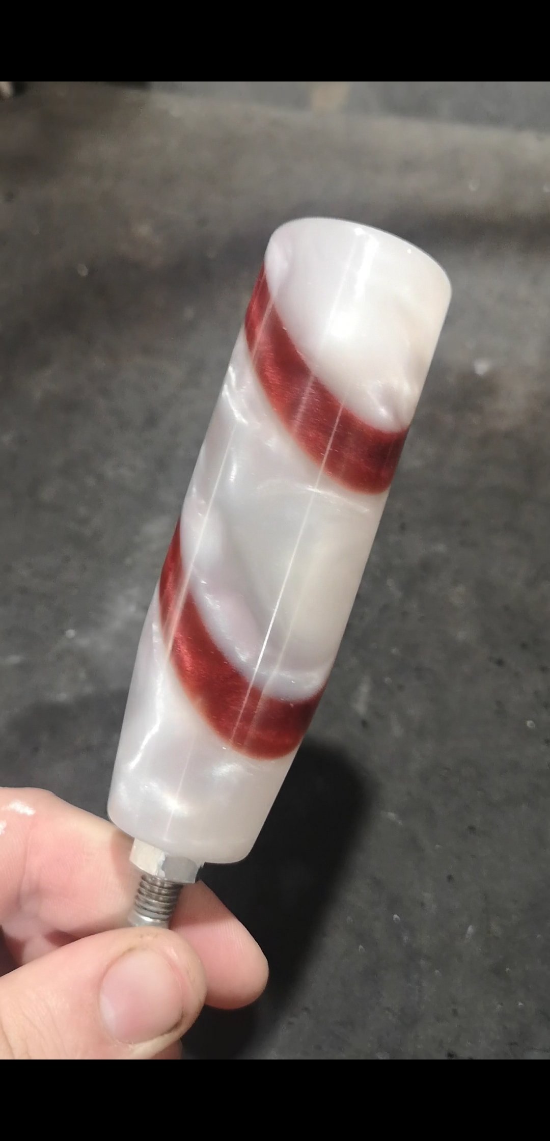
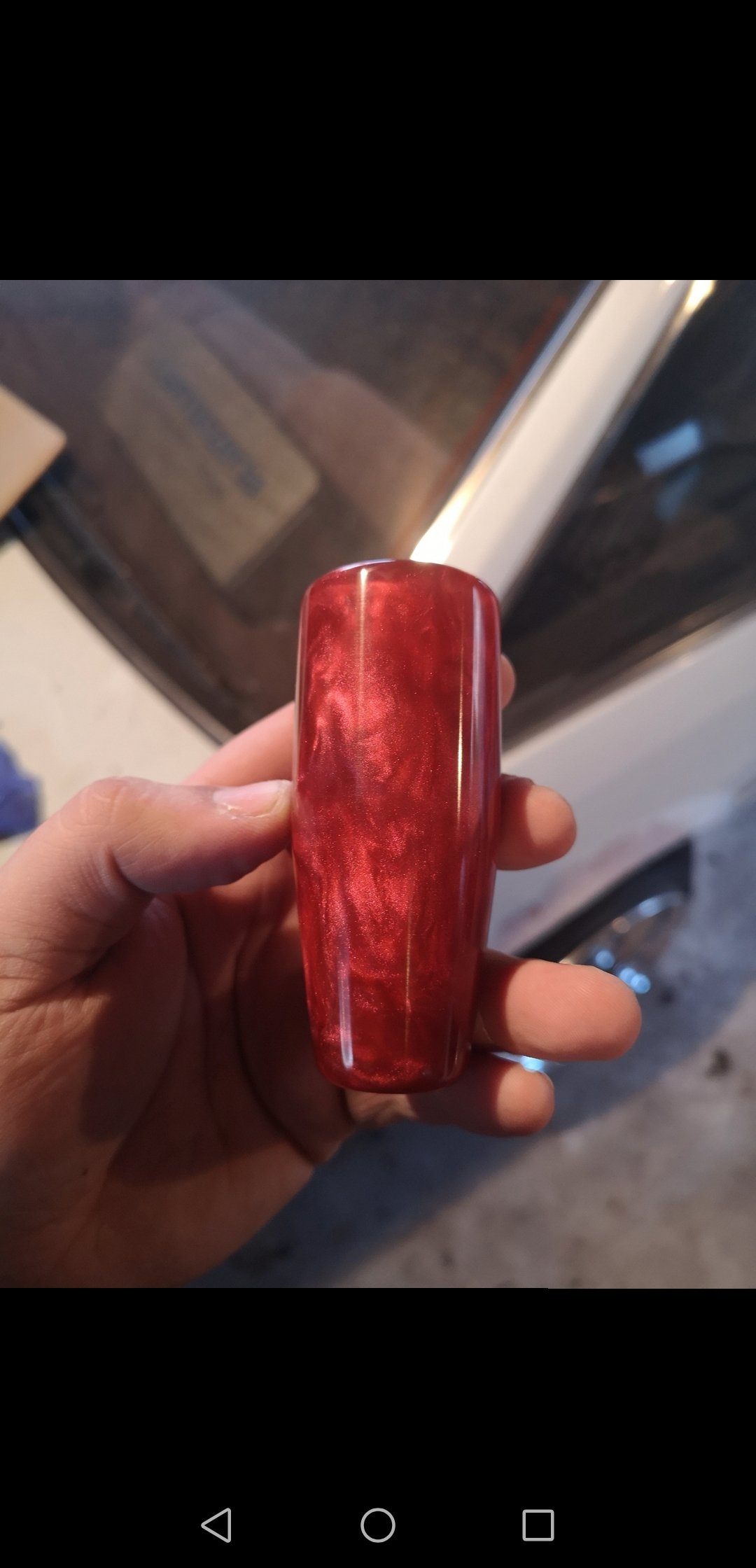
Been making some gearknobs recently for the intention of selling them eventually. A couple of done so far
1 point
-
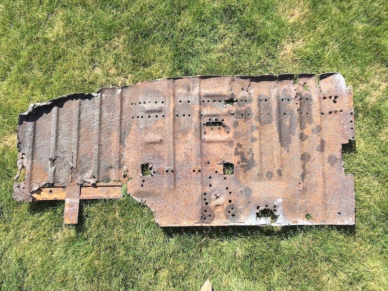
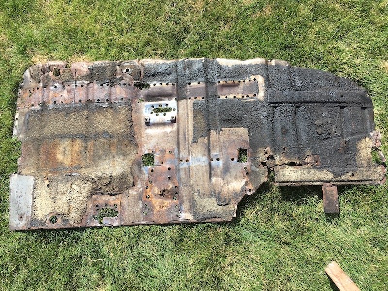
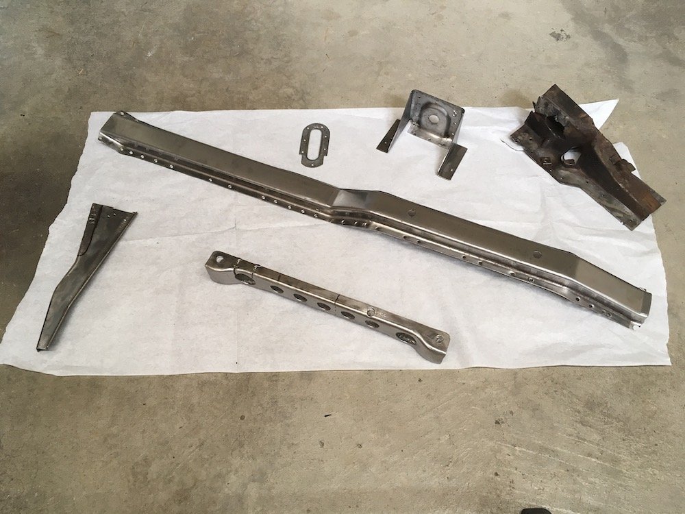
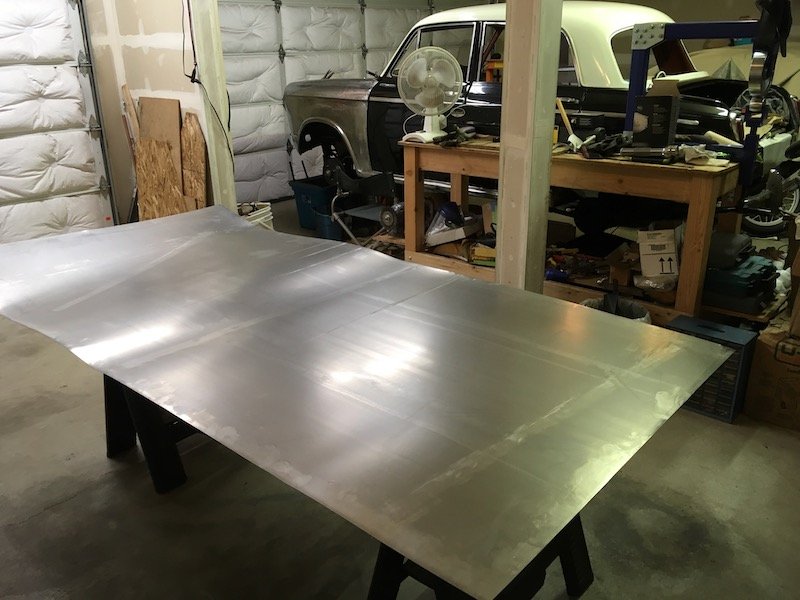
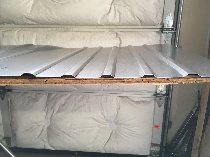
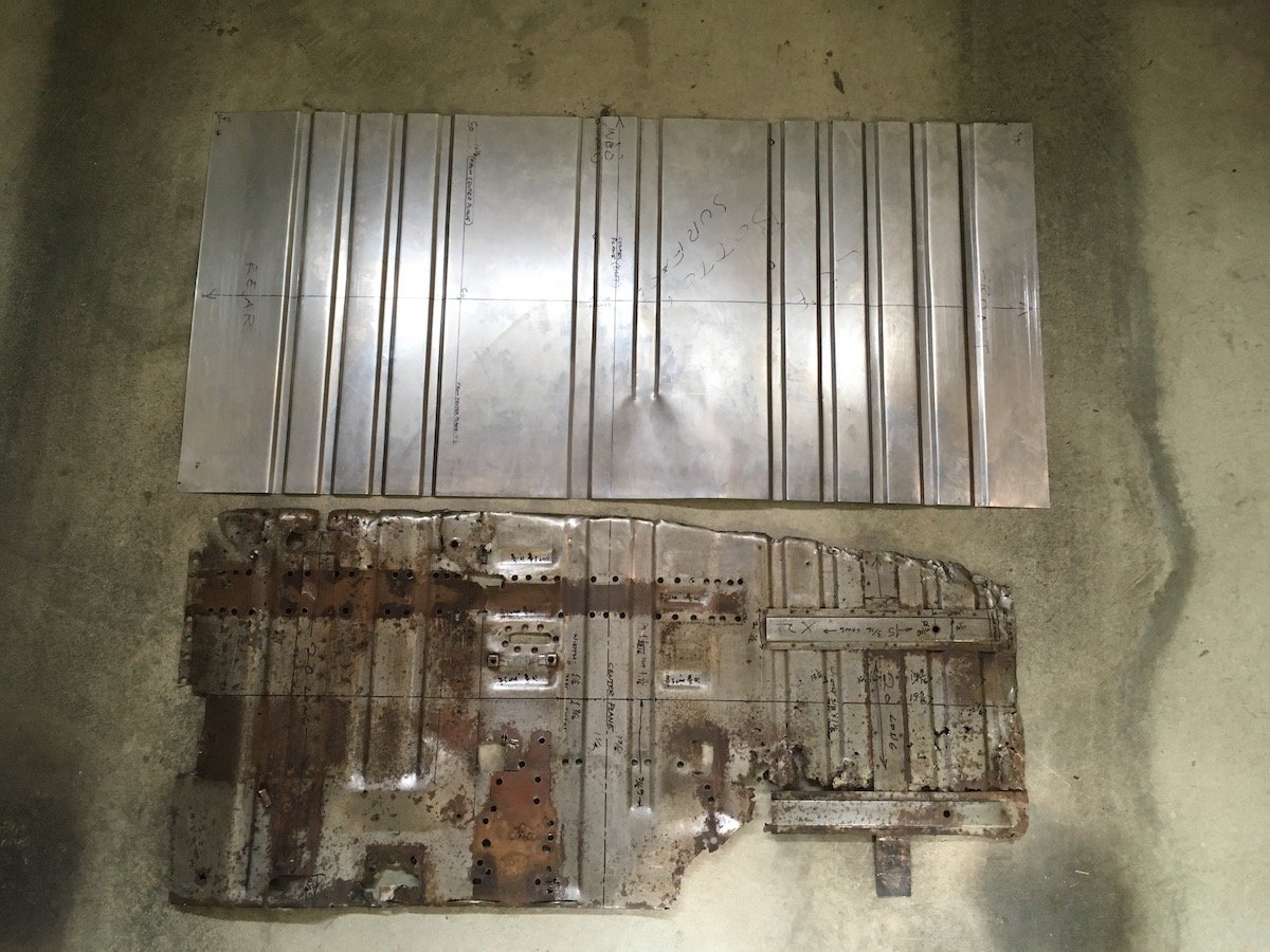
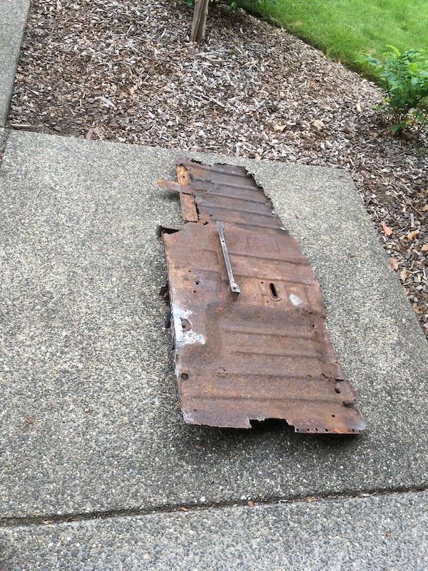
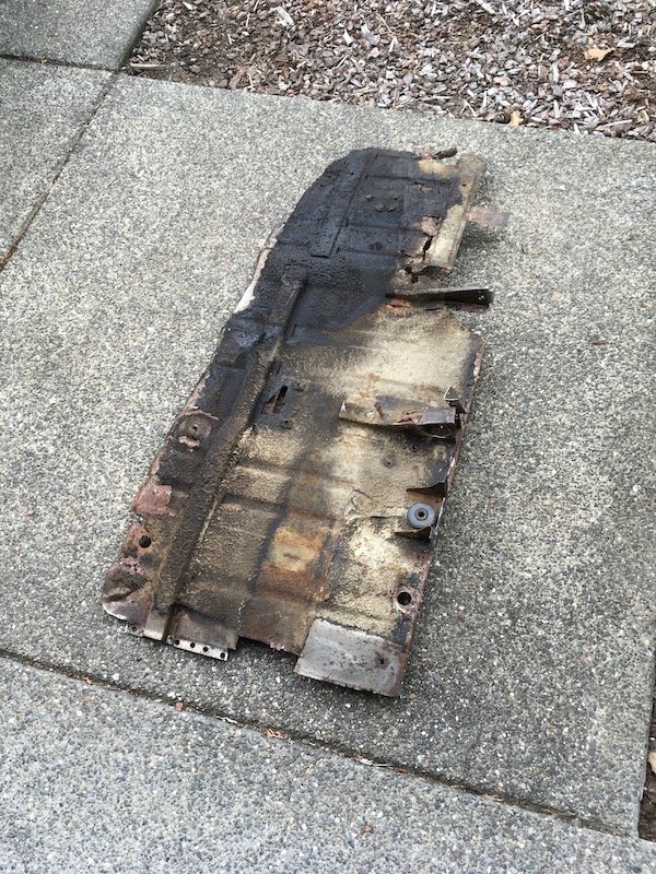
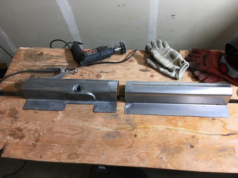
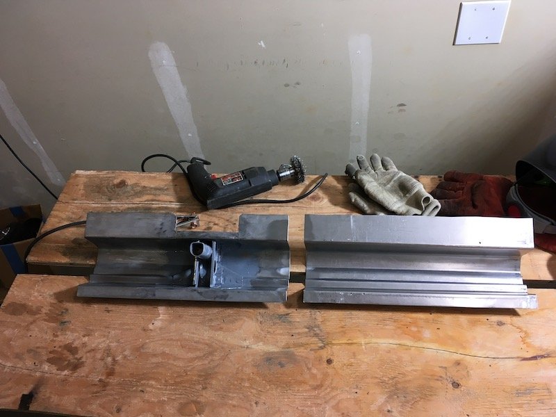
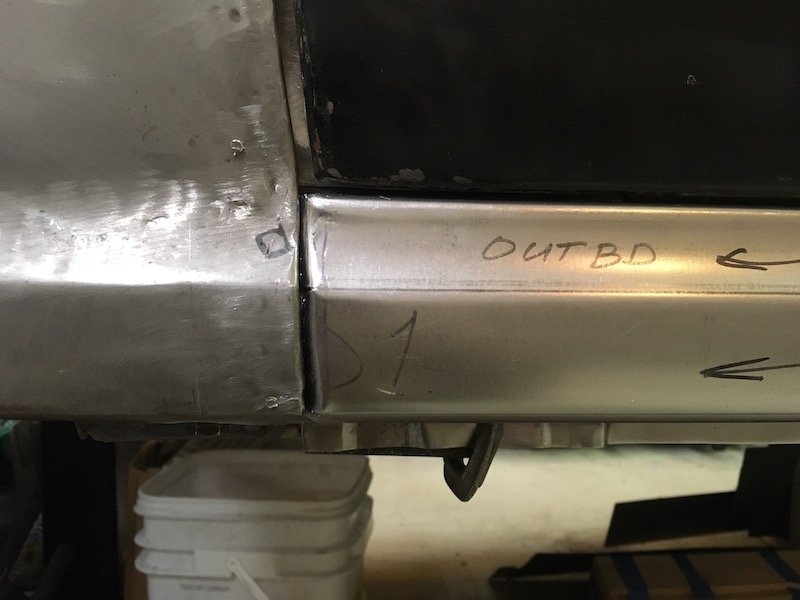
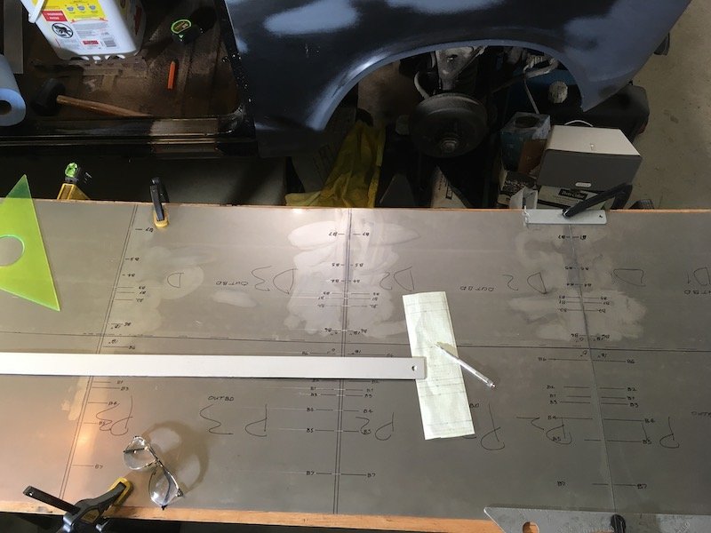
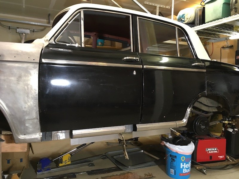
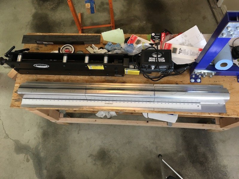
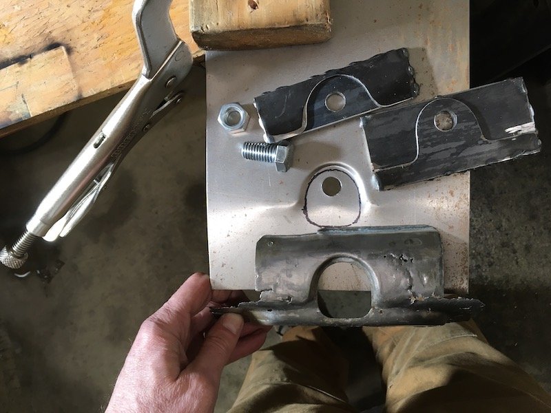
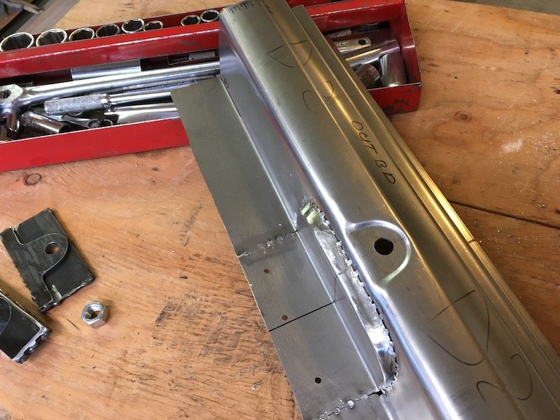
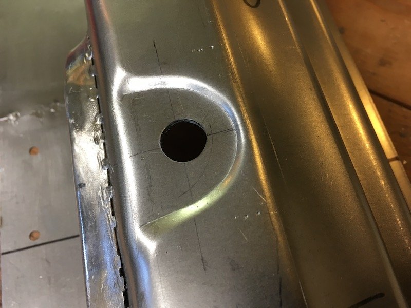
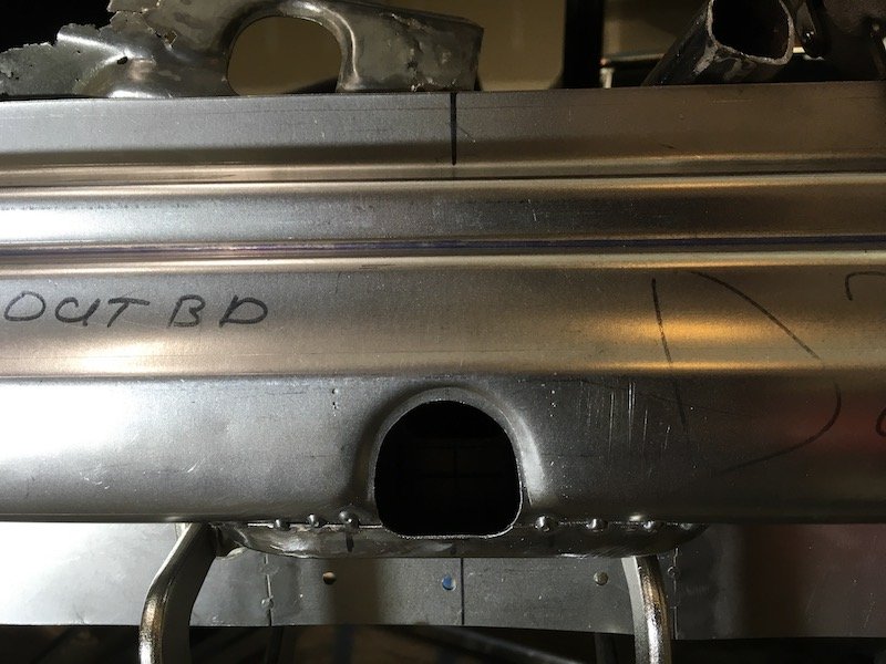
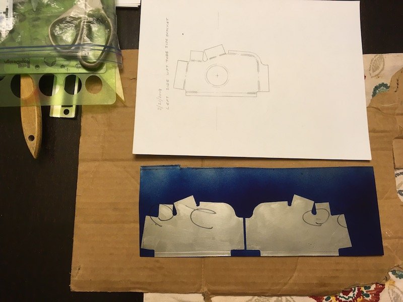
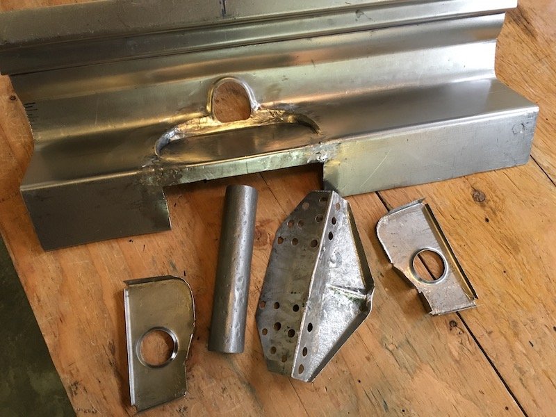
Back to work on reproducing the '61 310 Bluebird left side floor pan. First, I drilled out the spot welds to all the bits I wanted off the original floor. Top side Bottom side My collection of saved and de-rusted parts; including the seat bracket, longitudinal stiffener structure, hand brake reveal, B-pillar body mount bracket, and a couple of other brackets that are too far gone but get in the way. Bought some more steel sheet. Four foot by eight. I cut out a 26 by 56 inch blank and made some corrugated steel with a bead roller Scraped most of the under seal off the old floor pan bottom surface, did some measurements and began duplicating what was left. The bottom surface was more useful for measuring since it was much less rusty than topside. I'm leaving an extra inch or more all around to accommodate fit and trim later. Side-by-side compare Now I have to figure out a way to form some of the 3D shapes around the where the B-pillar body mount goes and the shallow depression under the hand brake lever. Hammer form over a wooden buck? Or form separate parts, cut the floor and weld in? Still have lots of work to do. Discussion: https://oldschool.co.nz/index.php?/topic/60267-marts-pl310-61-datsun-bluebird-sedan/
1 point
-
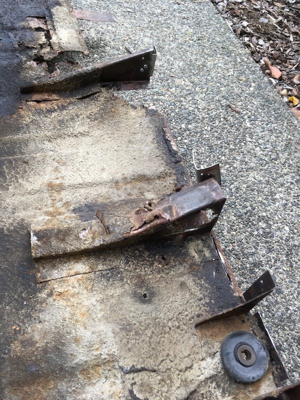
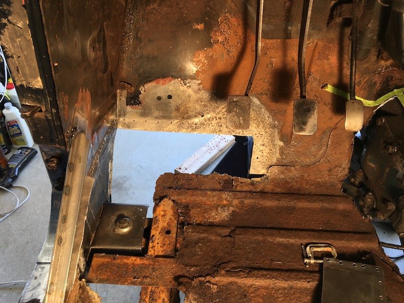
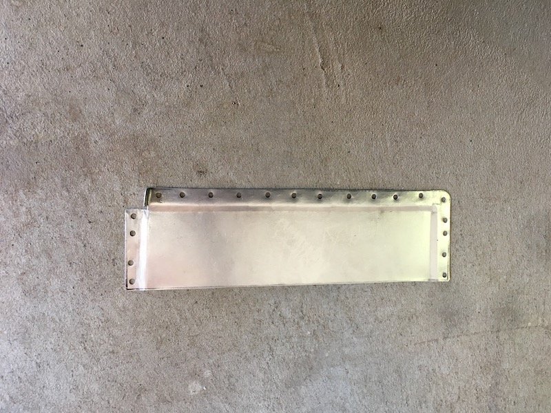
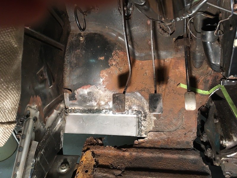
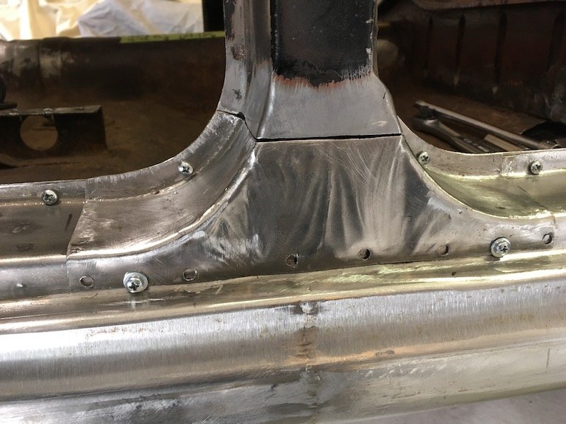
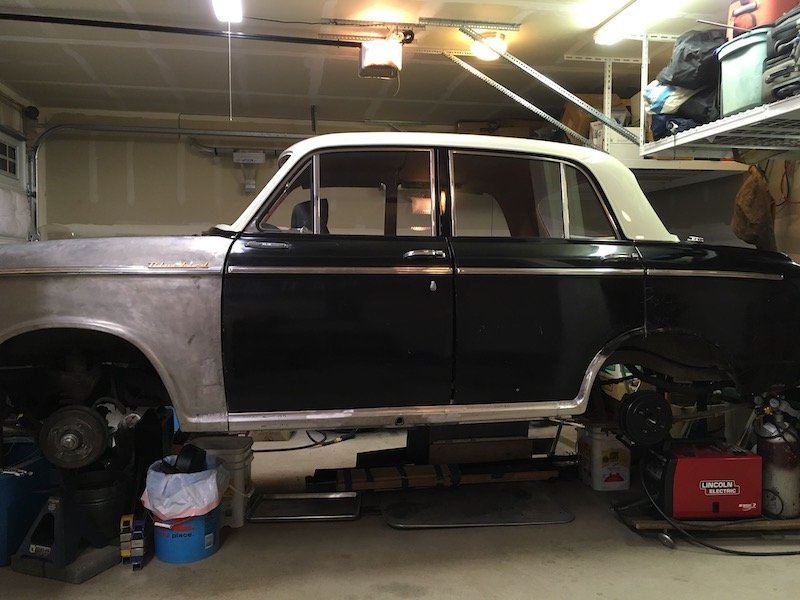
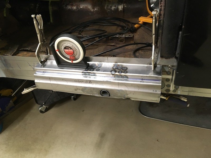
Continuation of the previous post with several more pics. The left middle/side patching of the rusted trans tunnel. As it started out with the fore and aft sections already tacked in. Made a patch to try and duplicate the existing contours and set an upper tape trim line. The black sharpie line was only a guide for torch heating the metal and asphalt undersealant on the other side to get it soft and scraped off. I didn't want my cutting tools getting gummed up. Cut the rotten metal out. Rubbish now. It would have been difficult to get a good weld against it. Cleaned up the surrounding metal. Did some test fitting to determine the trim of excess material on both ends. Final fit and ready for tack welds. Initial tack welds completed. With all the surrounding metalwork taken care of, I proceeded to cut the left hand side floor out. The seat mounting bracket will be salvaged. Same for the reveal or surround for the hand brake penetration. The underside. Planned underside salvage items include the long fore and aft 'Hat" section and body mount bracket. Other brackets are too badly bent, battered or rusted to be salvaged. There are four other simple flat or nearly flat parts that will be duplicated. I'll double up on whatever details are made to be ready for building the right hand side of the car. Never made a scratch built floor before, only patches and brackets. It's going to be challenge with the wide stiffening beads, elevation changes and 3D shape near the mid-body mount and rear footwell. No guarantee of success. Some random extra pics. Sleeping Bluebird with dreams of many road trips past and to come. I've now completely used up a four foot by eight foot piece of 0.9 mil thick sheet metal and need to buy more. Still got a long ways to go just to get the left side of the car finished. I'll post again later with more progress when I get the left side finished. It could be three, maybe four months or more. Discussion: https://oldschool.co.nz/index.php?/topic/60267-marts-pl310-61-datsun-bluebird-sedan/
1 point
-
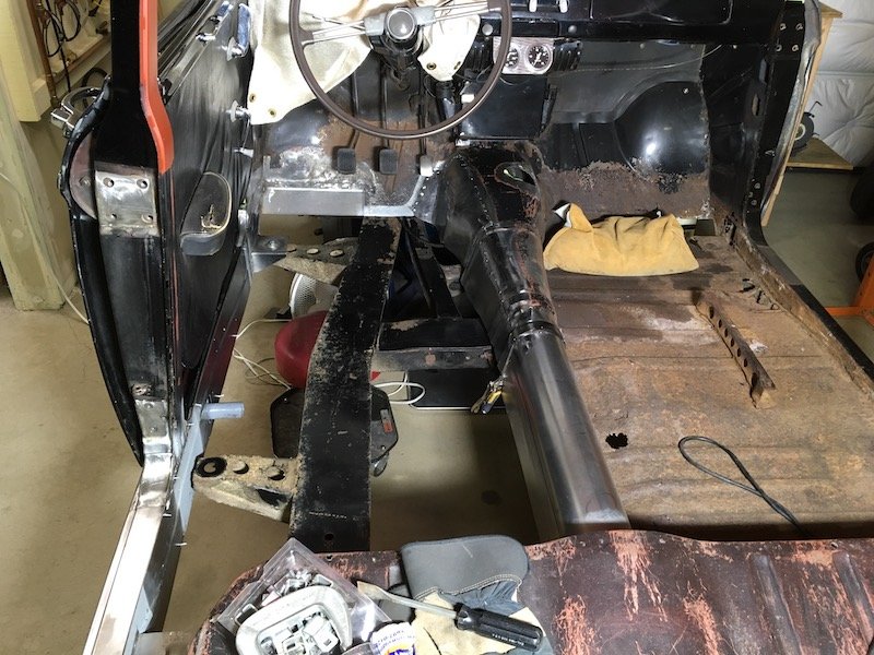
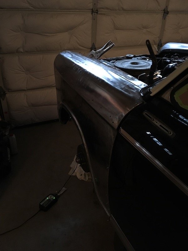
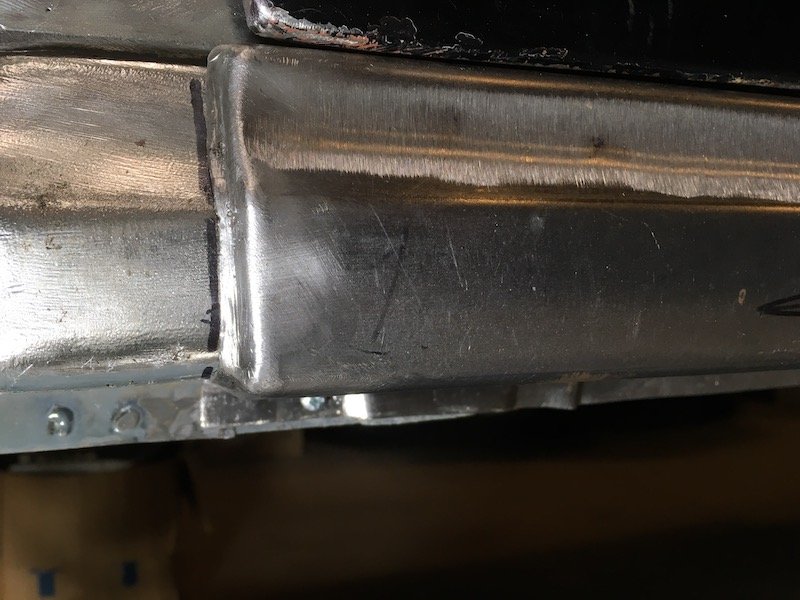
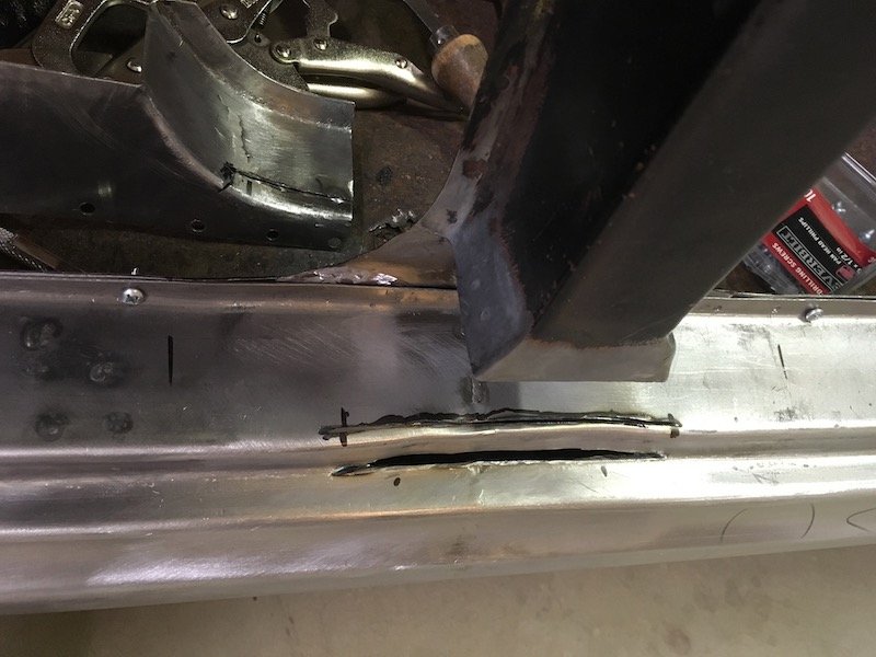
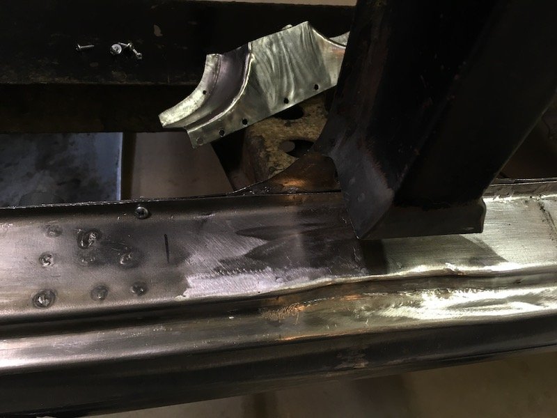
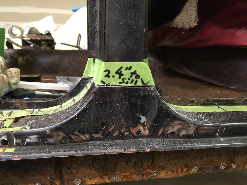
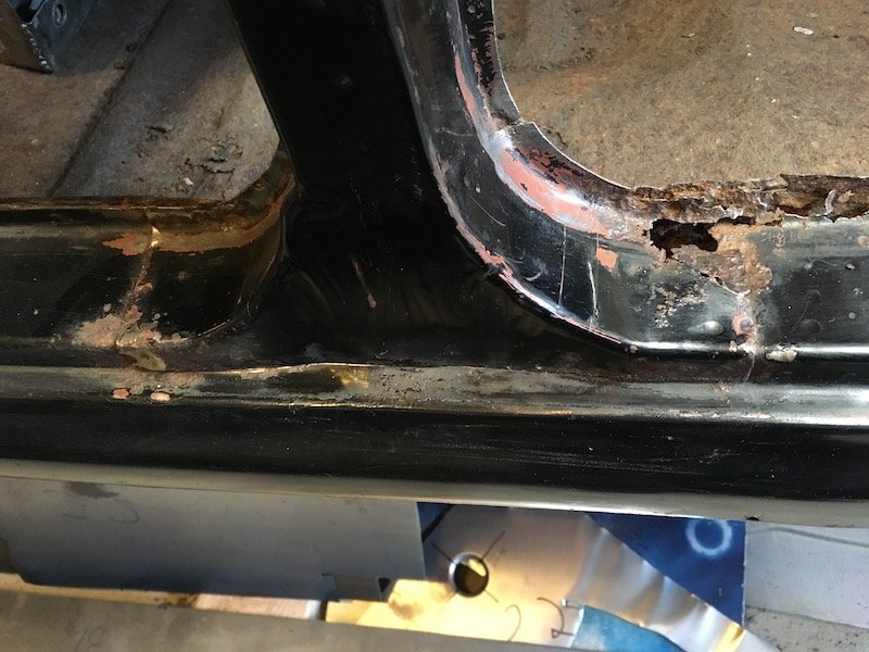
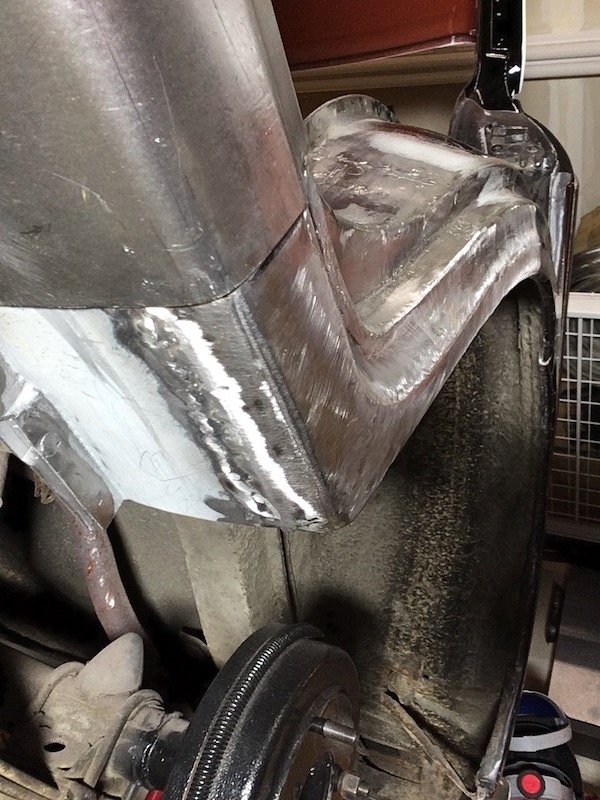
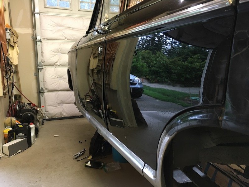
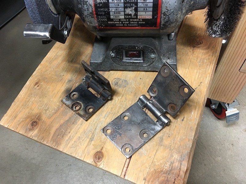
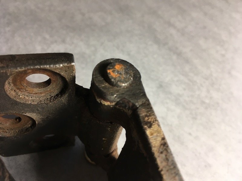
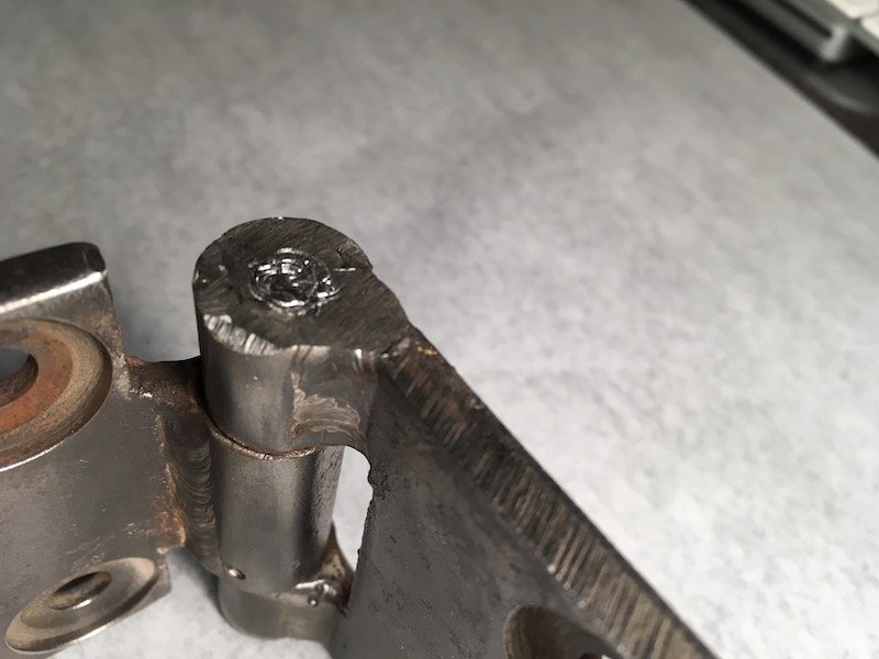
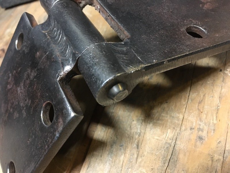
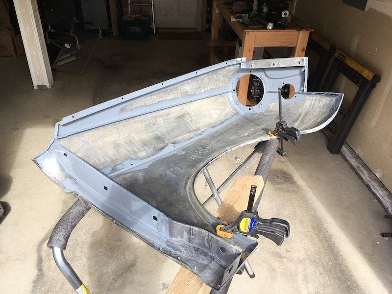
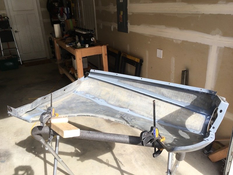
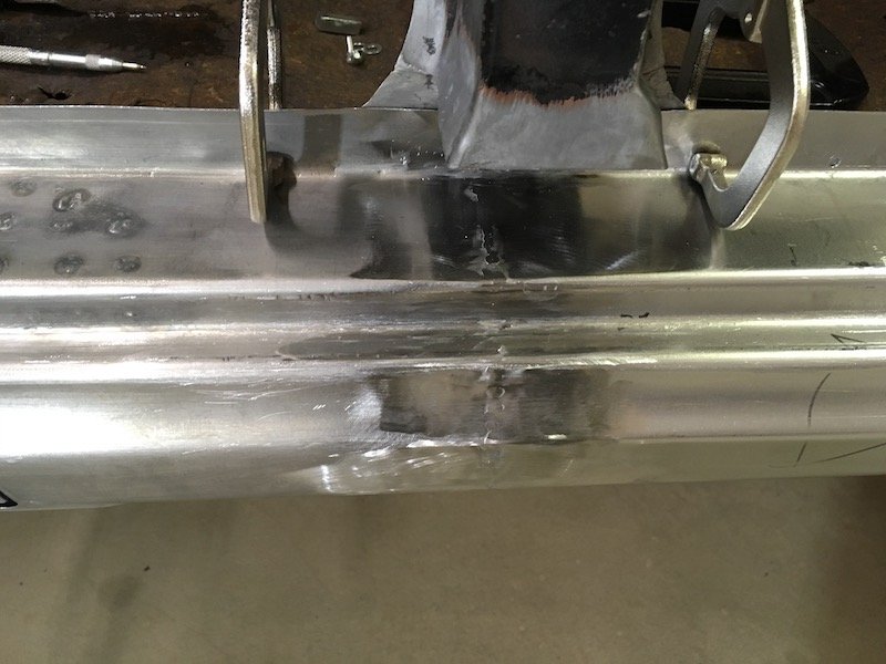
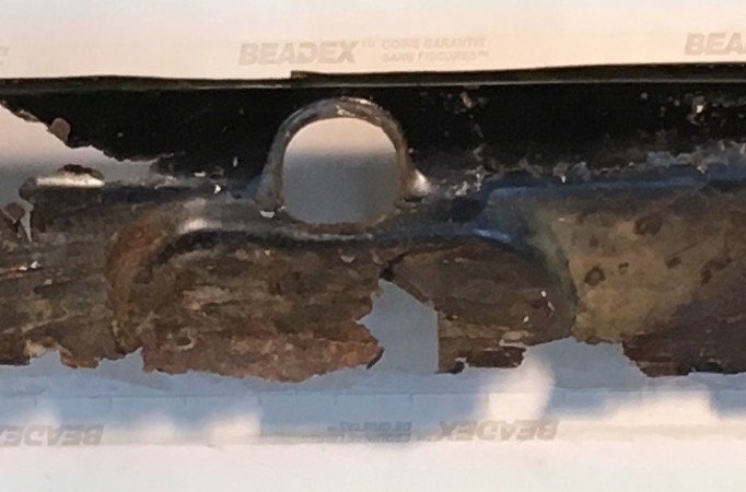
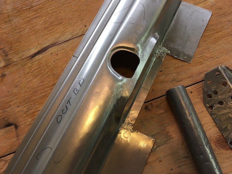
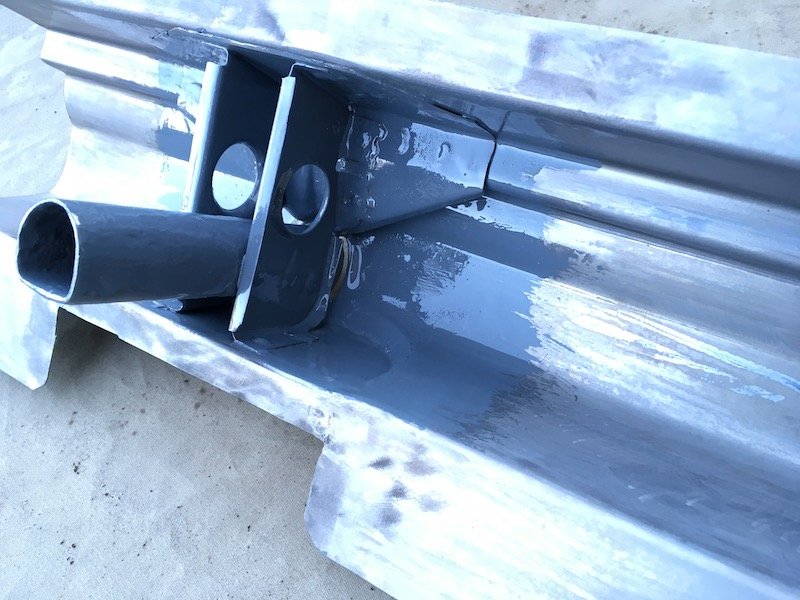
Catching up with progress today. Beware of this, my favorite tool over the last 26 years, the good old knotted wire wheel and angle grinder. Very handy but dangerous. Took a nip out of my flesh the other day. Ripped right through the glove. I should reinstall the guard of course. So I went to work by finessing the fit of the forward end on the outer sill by forming a lip on the end, making pie cuts and welding up the gaps. The objective to set it up for a flush contact with the A-pillar stub. Btw, the outer sill assembly will not be welded to the body until the floor is fabricated and installed so I can get a coat of epoxy primer over the resulting welds on the inside of the sill box. I've got it fastened with screws temporarily. Next, I had to make adjustments at the base of the B-pillar by joggling the upper surface of the sill inboard. Did this with some cuts, pushed metal in and welded shut. The top flange of the sill was originally joggled as shown in these left and right B-pillar base pics. Next I adjusted the C-pillar or dogleg. The bottom of which was tucked in way too far inboard. This resulted in an unacceptable mismatch with the outer sill profile. So I cut a slot in the bottom plate and welded in a 1/4 inch strip. Then had some fun time buffing out and polishing the now 42 year old repaint job on the doors. Don't ask why, I just did it on impulse. The doors do need repainting but it does not show that in the pics. I wanted to rebuild the hinges to make sure thing are fitting correctly. I grabbed the hinges off the right front door to experiment with. It did not go well with my attempted pin removal methods. First I tried pressing the pins out with a hydraulic press but it just began mushrooming the pin. Same for the big hammer and drift pin technique. And yes, I was pushing on the correct (not splined) end and supported the hinge properly on the other side. It looks like the pins will have to be drilled out. I'm not going to do that with a hand drill and not without sourcing new pins and bushings first. It appears I'll have to send them in for rebuild at a shop somewhere. Before I pushed against this end of pin Fail Fail Then worked on the left front fender some more. Welded the two halves of the aft inner vertical structure together with a lap joint for a rigidity. Cleaned, acid etched and painted rust scarred and pitted areas on the inside with POR-15 gray. Polished the outer surface with 3M scuff pads on the angle grinder to help see the waves and indentations better and work it smooth with hammer, dolly, rubber hammer, etc. I'll weld the inner structure to the fender once everything is coated with epoxy primer. And finally I set about repairing a bunch of damage on the trans/driveshaft tunnel. This 310 Bluebird has had the wrong transmission swapped into it back in the early 80s. The original trans wore out the 2-3 shift fork and this spare unit was installed but would not fit. So the side of the tunnel got torched out and it was made to fit. There is a huge difference in size between the two trans. The all synchro trans is a side loader, which is not only much wider but also longer. The original 310 trans is a top loader. Anyways I had to fix the gapping hole and make it adaptable to either trans since I still have the original and it is repairable. Then I went on to replace the aft section the covers the driveshaft. Then patched the rusty area midway between the other patches. All is just tack welded for the moment. Pics below tell the rest of the story. Below pic is looking up at side loader. The original 310 top loader trans. Above pic. It was no fun trying to do those three plug welds upside down. Notice the parallel hat section reinforcement structure or beams running fore and aft, I don't think these were installed on later 312 Bluebirds? Looks like I hit my maximum upload limit here for this post, and it is a late work night. Plan to catch up on the remainder tomorrow. Discussion: https://oldschool.co.nz/index.php?/topic/60267-marts-pl310-61-datsun-bluebird-sedan/
1 point
-
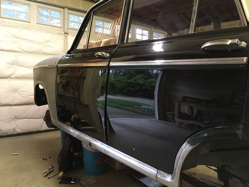
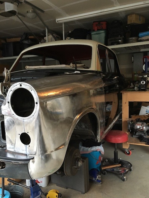
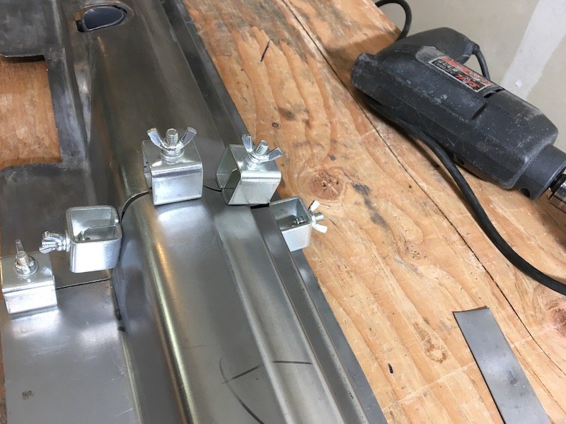
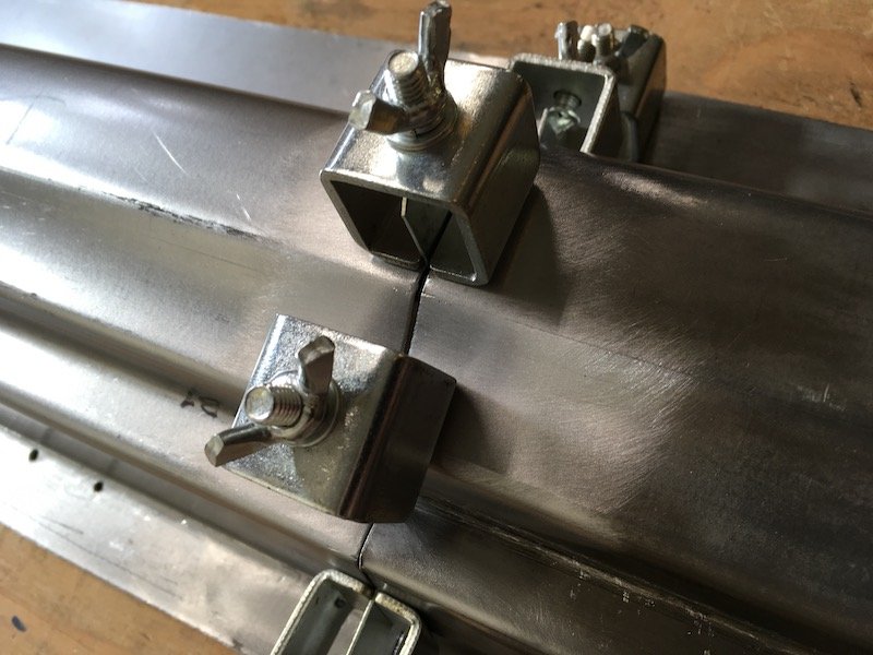
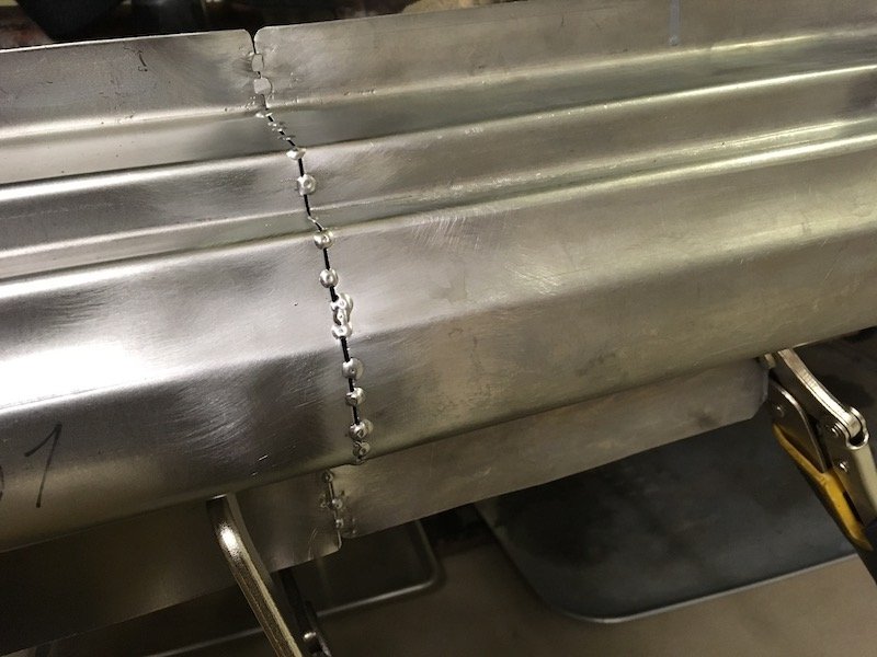
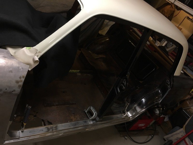
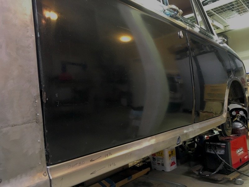
More progress with the Bluebird left side outer sill. Welded the three outer sill segments together. Started with these two shown previously Then I fixed the sill segments together with these little clamp things. These set up a nice gap to make good weld penetration to the back side. Then starting making tack welds. The first strikes in the center of pic were really bad and missed. Remainder of tack welds were usually on target. About 70 percent complete in these pics. Front and back side shown with good penetration. Front side will eventually get ground and sanded flush. Back side gets left as is. Initial grinding and sanding. After that I held the assembly against a bright light and check for pin holes, fill with weld and complete. It looked pretty good in a fit check against the car body. No weird wrapping or anything. Then on to the joining of the third sill segment to the assembly, same as the first. Except I was checking against the fit to the inner sill on the body before tacking, and after initial series of tacks, because there is a slight bow or curvature on the body fore and aft and I wanted to make sure of no issue. Did a little more rough trimming of the forward end as well so as to permit tailoring a nice fit up against the A pillar and lower stub later on. Finished weld of the last segment. Overview of the situation Then I decided to play with this. No, I did not actually try and jack the car up, just having fun with it. Later on I bolted the doors on again, probably for the fifth or sixth time, and did a final check for gap along the lower edges. Plus I formed the forward edges of the sill assembly to mate up with the A pillar stub with just the right gap next to the fender (or wing, right?) As seen underneath in above pic, there are several joggles along the lower flange to accommodate fit against several parts that are layered on the vertical inner sill plate. Below, the gaps look decent and body lines of door to sill are flush. Installed some trim to show off for the camera. Discussion: https://oldschool.co.nz/index.php?/topic/60267-marts-pl310-61-datsun-bluebird-sedan/
1 point
-
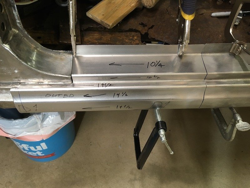
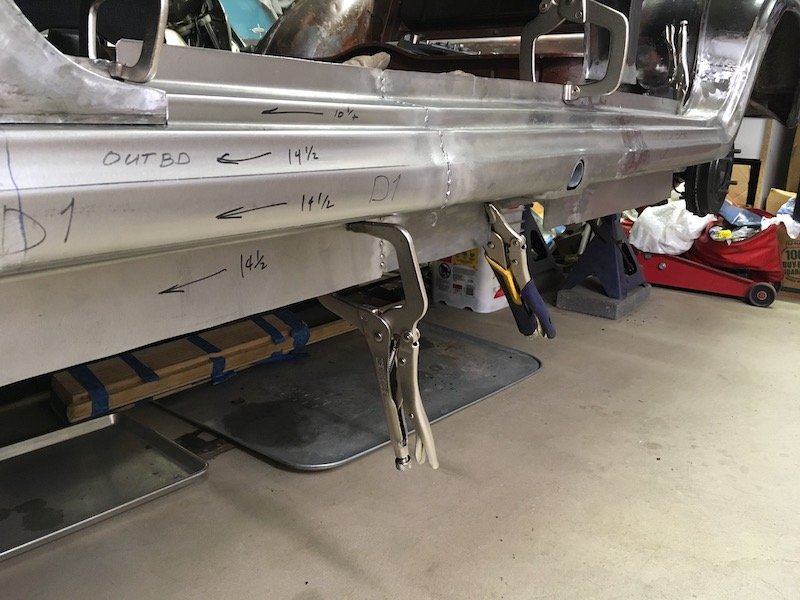
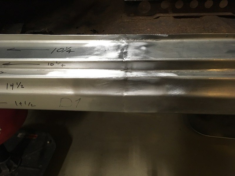
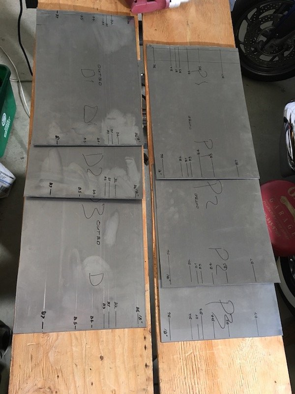
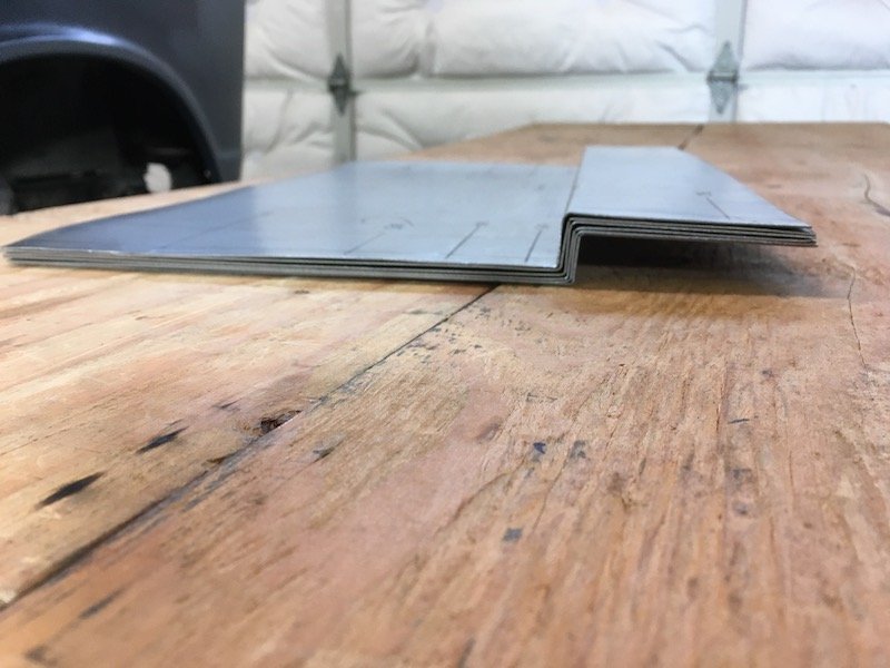
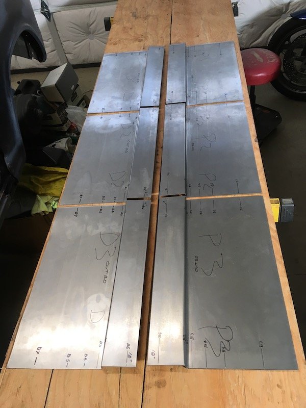
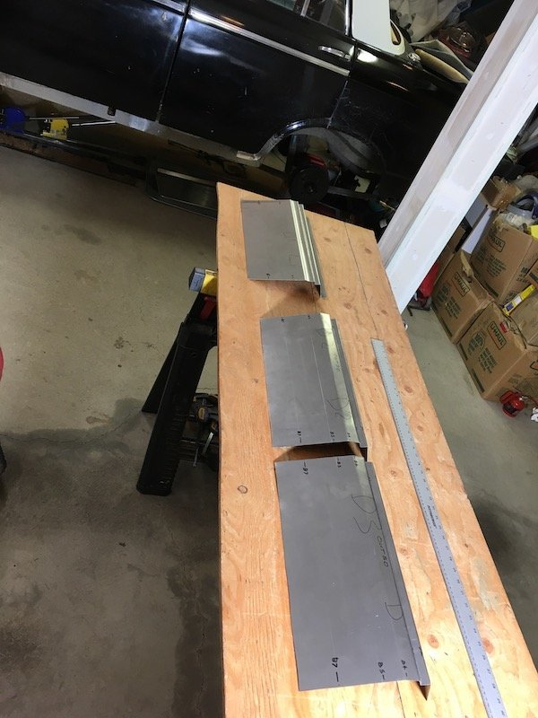
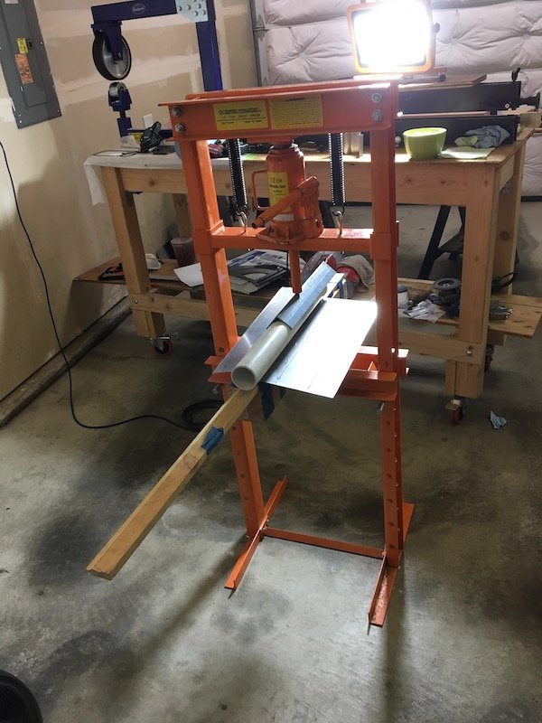
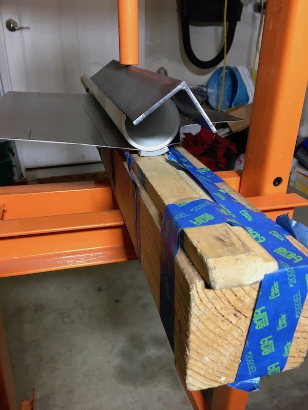
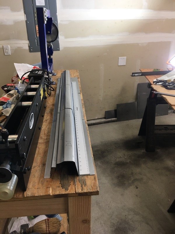
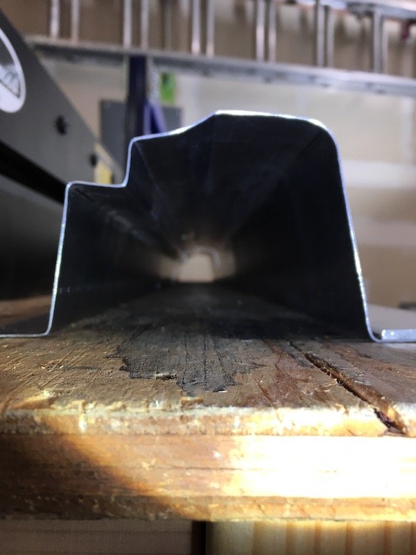
I got a little out of sequence. I should back up a little and show the making of the three outer sill segments that began about six months ago. Three segments because the metal folder tool only can do a 20 inch length maximum whereas I need about 54 inches total length. I also need to make offset bends. So there are a lot of challenges to make the sill. Makes it all the more interesting to have a go at it. Anyway, I have run into difficulties in duplicating the exact profile but it's good enough for usable parts on the left side. Maybe the technique can be improved upon for the right side. On the righthand side of the car I carefully measured and made a card template of the least rust damaged profile. Then began experimenting with and adjusting the seven bend line locations to figure out a way to make a sill. This is unlike a usual and simple sill that just wraps under the door more or less. The Bluebird has several visible body lines and a concave shape in-between. Plus there is the side of sill penetration for the jack lifting structure shown previously. This Bluebird outer sill is made of 20g sheet. Layout of bend lines The prototype profile Fits like a glove on sanitized right hand side Cut out six 18 inch long panels of 20g for left and right (D for driver's side or left, P for passenger side or right). Bend lines are marked more sharply by scribe marks so I can get good alignment when it comes to joining the segments together. B1 and B3 bends are offset bends and very close. This proves to be a problem Made the offset 3/4 inch bends for all panels (B1 and B2). Not perfectly uniform but close enough So far so good! As mentioned above, now I start having a problem at bend 3. This needed to be a tight offset bend from B1 at just over 1/2 width. The folder will only do 5/8 minimum (yet it was advertised as capable of 1/2 inch offset). Not good. I have to start compensating by moving the other bend lines to keep the visible body lines on target. The plan is to adjust the pillar bottoms to fit the adjusted sill profile, at least on the left side. I'd like a better plan for right side to get the true profile so I can leave the pillars unaltered. I'm considering having the folder plate milled down to get a true 1/2 inch offset bend, but that still leaves me with three separate segments to weld together. Either that or start over and make the whole thing as one hand formed piece by hammer forming each bend over a solid 90 degree edge of some sort. That might be wishful thinking. My crude setup for making the concave curvature between bends 3 and 4 Sandwich the sheet between plastic pipe, angle iron and squash it Checked out the fit of a couple of segments relative to the doors and the lower edge. Checked out as good. Three completed sill left side segments lined up on the rollaway workbench. Decent alignment of three segments. Looks like I can make it work when it comes time to join them End profile view of three outer sill segments all in line, just for kicks Discussion: https://oldschool.co.nz/index.php?/topic/60267-marts-pl310-61-datsun-bluebird-sedan/
1 point
-
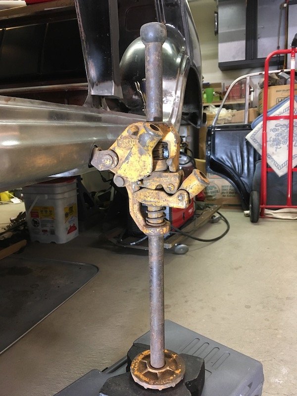
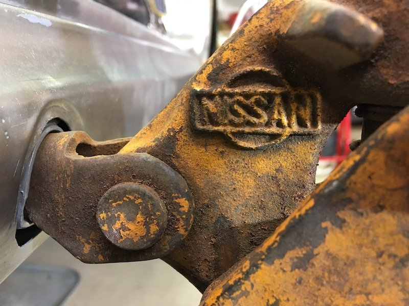
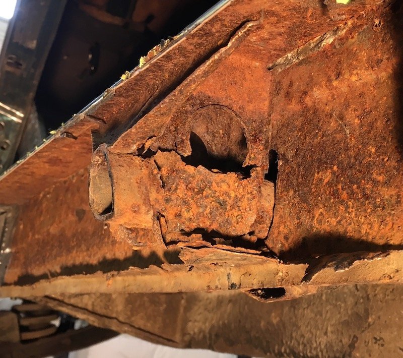
Build of the lifting jack structure Original outer sill panel where the lifting jack pipe was Inside the sill are the remnants of the jack bits Made a forming die to recreate the indented outer shape, test looked good on scrap piece so went ahead Simple as sandwich the panel and tighten the bolt Looks not too bad! Closer examination. The extra metal around the bolt hole gets trimmed out to match original. The lower pop out section (to left) is welded on and then cut off. Wrong position darn it ;( Straight on view after trimming Moving on to recreate the inner vertical stiffening brackets. Takes a bit of imagination since only about half of the originals remained Bits getting ready for weld Checking bits out for fit Sand blasted the original pipe free of rust Now really ready for weld Welded and checking results for fit against inner sill Coated with POR 15 for future rust protection. Turns out this coating can catch fire real easy and sustain flames. Next are the three outer sill segments to be welded together. I've kept a lot of extra flange widths, top and bottom, to resist warping. These flanges gets trimmed back to about 1/2 inch. Discussion: https://oldschool.co.nz/index.php?/topic/60267-marts-pl310-61-datsun-bluebird-sedan/
1 point
-
Hello,, are you still in the northwest ? Have you heard of a Datsun show that was held in a town called Canby ( south of Portland) .. Well that show was ran out of fairgrounds by the powers that be ,, so it has been moved to a place just north of Salem called Powerland NW .. It's a huge place that normally hosts tractor/thresher shows... Anyways,,,, if you never been, there is usually over 200 Datsuns from many states and Canada.. Even if your car isn't done you should go to it,, it's a great way to charge your Datsun batteries.. A 2 day event,, Saturday ( there is camping on the grounds) , and ,, Sunday is usually a early end ( 2pm-ish) as there's tons of guys from SoCal that need to start their trek home.. There is apparently tractor museums you can go in, on the premises ( first year being held at location so don't know what's in them) Very low key and such, and most owners are older so not a shitshow of 20 somethings doing donuts.. This isn't my show i only go June 8-9th http://www.antiquepowerland.com/index.html http://www.antiquepowerland.com/html/calendar.html <<< calander,, It says Japanese vehicles but it's only Datsuns and older Nissans / Cedrics Really bad video i did in 2017(?) ,, there are about 30 or more cars behind where i started walking from and some that never really leave "camping" area all weekend Not sure what My son and i are driving this year yet,, but probably one of my usual 411s OR 410 project i am putting off because of bathroom remodel . and sons got a A10 2door project ( he normally drives A10 wagon) he was hoping to waddle down there in. He's behind on that as it's been so cold,,, and being a 23 year old he is easily distracted . Did any of that make sense ?? lol .1 point


.jpeg.9062206fae4687c28fcac634f9f6ef31.jpeg)


This leaderboard is set to Auckland/GMT+12:00