
Leaderboard


Popular Content
Showing content with the highest reputation on 03/18/24 in Posts
-
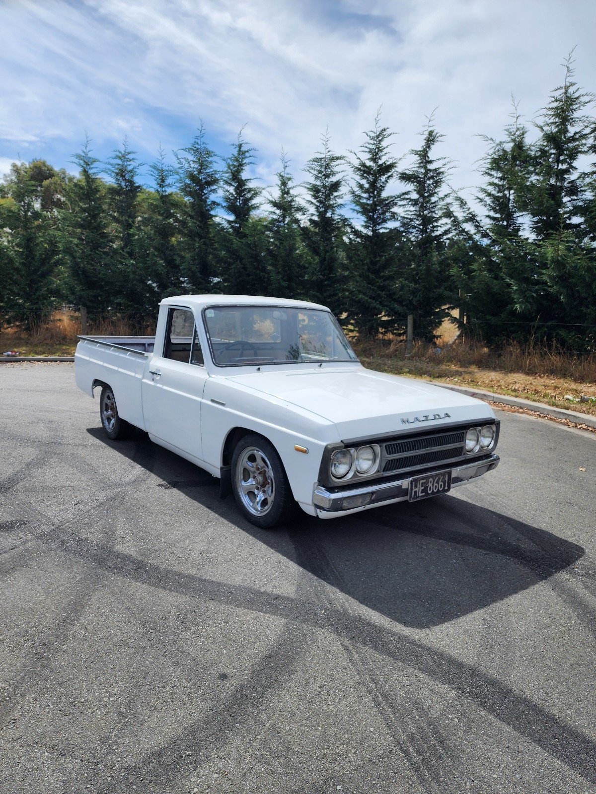
Well after the last novel length wall of text I'll try to keep this update shorter otherwise I'll never finish the thing. Lots of little jobs starting to pop up on my 'to do' list. Driveshafts. Connecting the scooby shafts to the imp axles. A job I wasn't sure which direction I'd take as there's so many different ideas out there on the nerdnet showing 'the best' way to join shafts. First thing I did was to double check the suspension travel allowed by the stock shock absorbers and then use those datum points to work out if there was any growth in the length of shaft required as the wheel moves through it path up and down. There was minimal amount, like maybe 5mm at the very most. I guessed as much because the stock Imp driveshaft doughnuts dont allow for much sideways travel. I then cut one of my 22mm scooby shafts down in length so I could work out the lengths required with the CV joint in place. This move I soon regretted. I was allowing for plenty of plunge into the CV joints to make sure the whole joint could be removed from the box stub axle with the box pushed sideways when removing the transmission. I was happy with the length and then decided to go visit a local hotrod builder friend for some advise. He's well known about for his many many full scratch builds and has done heaps of driveshafts in his time (a fellow machinist by trade too) I showed him the two ways I was considering doing the join. He showed me a better way. Shrink some bored out yokes cut off from some spare axles. Plenty of meat, will never let go and even if they somehow did loosen and spin they cant come out because there's not enough travel in the CV joint to allow them to. No welding needed. He's run axles done in the same way with some serious big block power and they never let go. Just has to be accurate and luckily its the sort of machining/fitting job I like. But i needed to start with almost full length scooby shafts to do it, of which I was now down on.. Roll eyes and back to the wreckers to see this beauty get pulled from the hedge... Hannah helped me remove the shafts. It was her birthday too so wow, what a treat. She got visit the wreckers and get oily. Got home and the shafts didn't fit my CVs. Bigger diameter end. Really weird because I checked online... ha. It lies. Turns out some late 4wd Leones had even bigger axle ends than the imprezzas. Also odd is that one shaft is 22mm and the other side 24mm, although both the same length. Back to the wreckers. This time I got larger 25mm shafts with the smaller ends from front wheel drive Imprezzas. I grabbed two pairs. Same again, 22mm on one side and 25 on the other. Now I had two of each. Got home and spent some time cleaning them up, outside because petrol fumes. Cleaned up the spare pair of axles in the lathe to make sure I had an accurate clamping spot for the later boring. Good quality steel! I turned them down to less than the 23mm bore size and chopped the yokes off. Made lots of swarf Bored out to bang on 23mm with nice radius. Double checked and triple checked I had my lengths required correct. Chopped the two 25mm scooby shafts down to length and turned a step down on one end of each, a radiused step to stop any stress risers. I went for .0015"~.002" interference. Go online and see the debates between all the barries about what a good shrink fit should be There's many variables as well. I consulted my old faithful machinery's handbook. I wanted it tight, but not stressed. Luckily the axle is of good steel. I also made a sample first, using one of the cut off bits of scooby shaft and some 4340 I machined to the same outer dimensions as the yoke. This way I was able to test how hot I needed to get it to expand enough to drop in place. I'll take this to a local engineers who have a press with a pressure gauge and see how much force it takes to wreck this thing Here's about a one hundredth of a millimetre (iirc) getting removed.. Then things got hot.. photos taken after it was done because I had to move bloody quick! Hannah would grab the torch and I would drop the yoke in place. It was a tense bit of time. If the yokes teetered and grab they'd pull the heat so quick and shrink in place before getting to the shoulder. No removing them without damage and I only had the one pair of spare axles. It went well. I was happy and relieved. The light rust flashing off on one is simply due to that one having been left nearer the front of the workshop to cool down and it was a chilly damp start to the morning. They wired brushed up neat as, got painted with black epoxy and when that was set they had new universal joints fitted. I cant try them on the car until I remove the existing axles from the hubs but it should be fine. Next up was to sort the fuel tank out to suit fuel injection. I brought the blue imp in and checked a few ideas out on what I could do. I don't really have room for a surge tank and I never liked the noise on my Viva from the external fuel pump anyway. Nor did I like the way the fuel in the surge tank heats up. Enter the humble Nissan Micra k11 intank fuel pump and surge container... It actually looked like it was just going to fit into the pressed depression at the bottom of the imp fuel tank.. With enough room to run the imp fuel float sender next to it. Cut a hole.. It fits. I'll cut the bracket off the side at bottom of pic and it'll move sideways a bit more.. Made some metal brackets Welded them in and now I have a cradle that takes two cable ties across the top to secure. I needed a flange.... Made this. Its designed to recess the lid about 10mm below the tank top. I want to keep the tank top as flat as possible. It'll have the usual layer of foam over top but I don't want things sticking up proud when the 'frunk' is being used (cant be tearing those bags of concrete now eh....) Many holes drilled and tapped.. Carefully welded in place. Was a tricky job. Thin steel on the tank that had some sort of (probably poisonous) coating. But happy with result. I made another hole... That takes the sender. Drilled and tapped more holes to suit. Now I needed to get fuel from the outside in and from the inside out. I machined up these in stainless.. Thought of a neat way to hold the little bits together for tacking. Blue tack. Or blue tack tack? welded up.. I made an angled recess into the hatch cover so the fuel hose goes even further below the tank line. Visible in that photo are the cable connections. Again - I needed to get power in. I machined some shouldered fittings in plastic.. Luckily the micra pump so handily just uses a simple connector with 6.3 spade terminals. Under the lid... Tank hard work done. I'll paint bits and cut some gaskets. Speaking of gaskets. One of mine between my oil filter pedestal and the block is weeping oil. Plus one of the bolt heads weeps. Typical. Put a Japanese engine in a British car and turn your back for a minute... I've already drained the oil cleaned it up and ran a smear of paintable sikaflex along it and around the bolt head. I didn't take photos because not really exciting. I'll paint it silver and no one will know. Except you the reader. Next up is the exhaust I think.19 points
-
Some bits from the UK arrived surprisingly quickly, a sump and tappet cover gasket, a boot for the gearshift, suspension bushes etc; I made a battery bracket to suit the most likely battery I found in my stash of many; All those untidy wires are not part of the car you will be pleased to know. I also printed some things; Cos that link for the lock on the passenger side has gone walkies somewhere. And over the last couple of weeks I have been designing and iterating a set of heater controls that I think actually should work. Cool beans. Also I wired up the clock. It works all nice. The clutch couldnt get uprated cos they couldn't find the parts to do it and additionally the man said it looked like that cover springs had been over extended, this might mean it was slipping due to wrong adjustment, so I will order a new standard clutch and see what happens. Also I found another X1/9, and have spoken to the owner, so there might be a very small Nelson X1/9 owners club.9 points
-
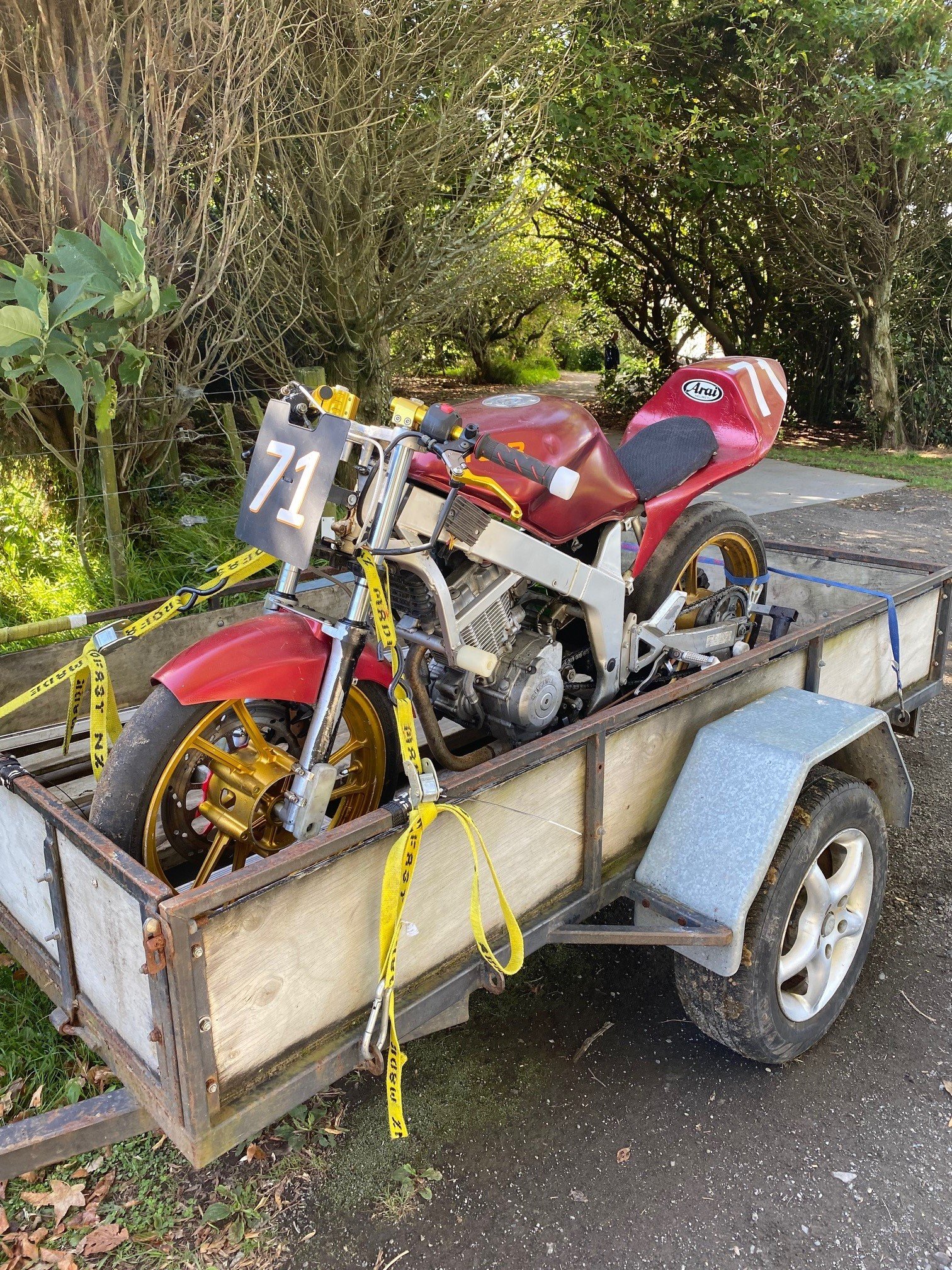
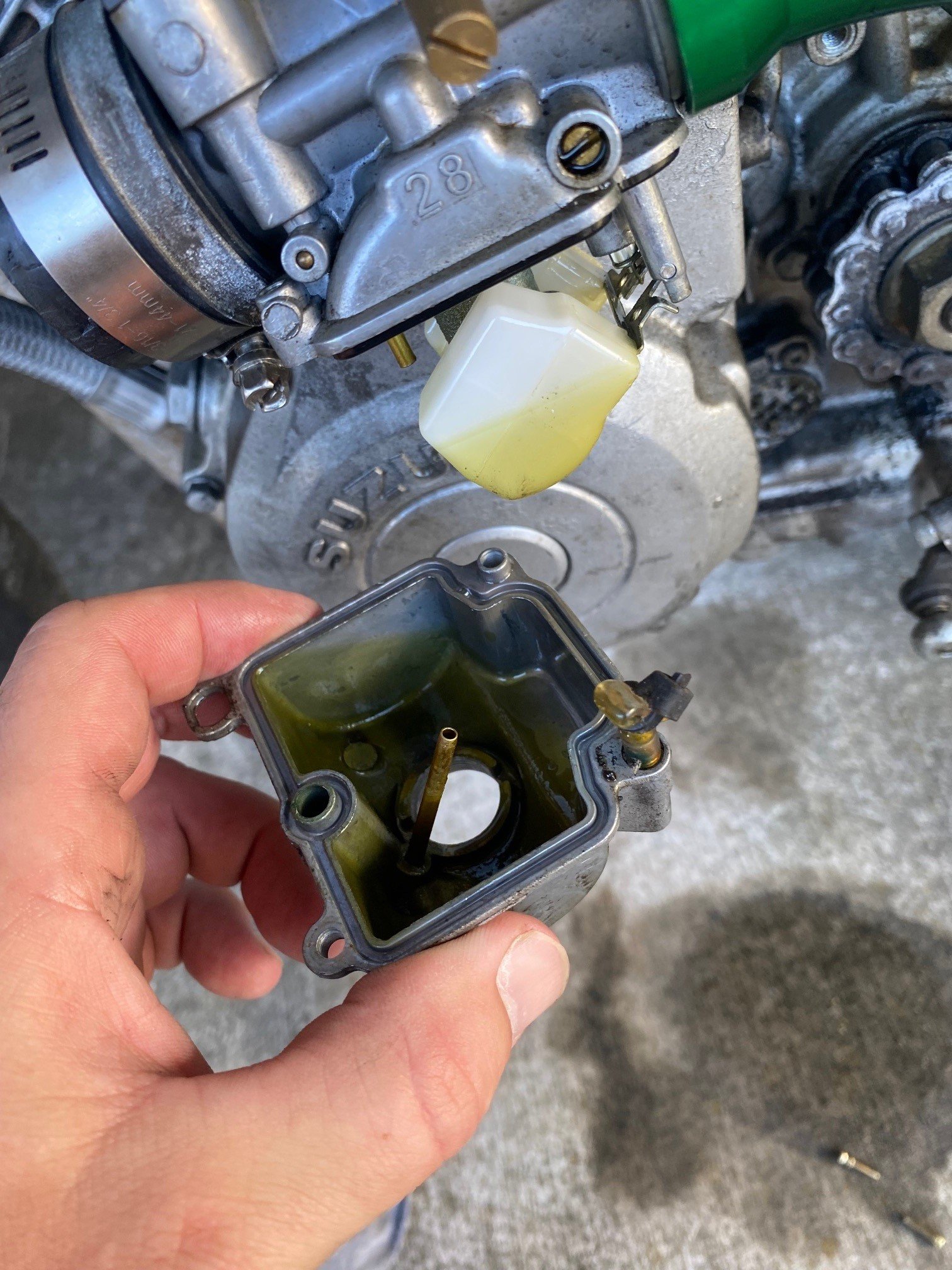
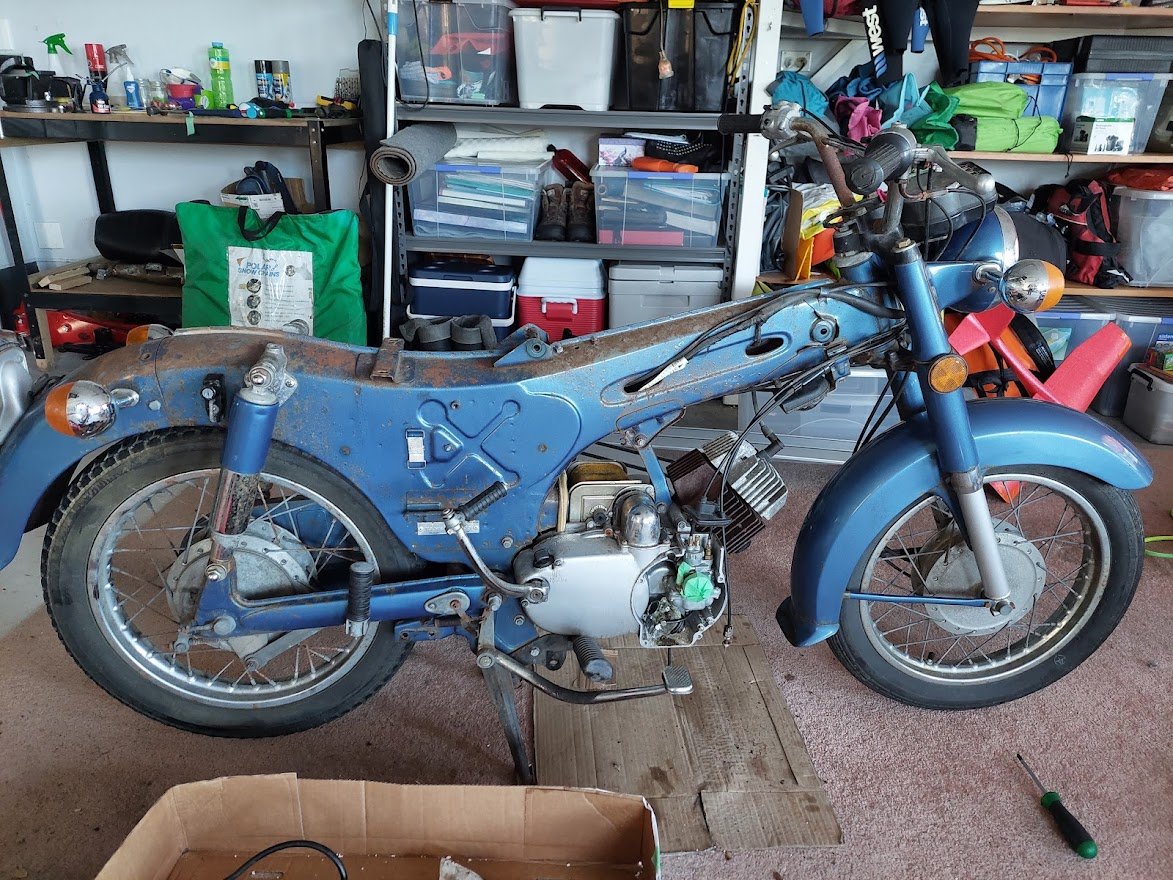
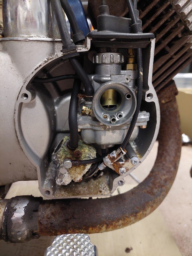
I also did a deal with @Itchybear and now I own this: Its another FXR150. Purchased for reasons that will become clear later on. I took it out to the track yesterday for a quick test, it hasn't been run in years and the fuel was rotten as. Stunk out my pit box for the whole day Anyway, gave it an impromptu carb clean and it was away. Needs a tune up, but its quite nimble and handles a bit better than my bike I reckon. I think having a much lighter engine than the CBR250 donk means the springing is a bit off on the castrol bike, so I might have to play with that now that I can measure the lapspeed.
 5 points
 -
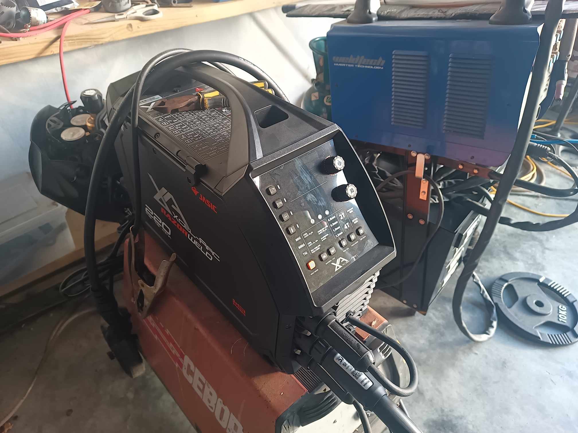
Ended up getting the floor model which has been superseded for a hefty discount. I gave it a quick whirl and the welds come out very smooth indeed. I have a bit of panel work to do on some thin stuff so I'll see how it likes that. Thanks for the hot tip, gents.
4 points
-
Did some more suspension fettling @Snoozin put it in print via nzpc Now looking to sell and onto the next one in garage! Would like 35k on the tomcats 25k on CHEVIOT TURBOS
3 points
-
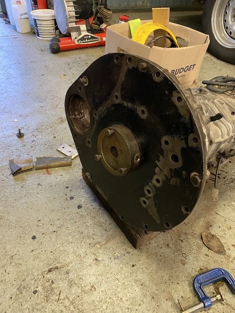
I glooped the two halves together, bolted them up, bolted the tailhousing on and let it set. Following morning it was bolted onto the engine, unsurprisingly a bit heftier with all the gubbins placed back within the box. Its about 9kg heavier than the standard imp box. I then started to fit the first part of the gearshift linkage. The first of those snazzy universal joints, handily available in a diameter to suit the shifter shaft on the Subaru box. I just needed to add a small locating hole for the grub screw... Universal in place.. Engine and box were then bolted back into the car. This bit is so quick and easy when using the 'engine stand 2000'. It takes about 10 mins and I'm getting quicker. It'll be slower when there's shift linkage to undo and driveshafts to slip out of the way. But at least the main heavy awkward part is actually easy. That lot in place I took some pics. Its neat to be able to look out from the one of the lounge room windows down onto the workshop floor and see this... With that lot in place I was able to suss out the angles I could get away with, as shallow as possible and allowing for the handbrake mechanism. I had this old imp gearstick assembly that @dmulally kindly posted over to me. Some previous owner of the car he got it from liked painting things. Everything. Multiple times... I scraped all the layers off, took it apart and cleaned off the dirty old grease. Discovered it had been cobbled together from two old shifter bases. It was originally a very early Imp unit when the very first cars had an automatic choke, which often proved problematic. Hillman then changed the cars over to a manual choke with a nifty little lever in front of the shifter. This mount had been added to the early base. Which means they must have chopped up a later baseplate to get the choke mount. Why they didn't just fit the entire newer base plate I don't know. But what I had in front of me was a frankenstein of base plates with barry spec welding and fixes, but also including a not too badly made bronze bush on the lever where there is normally a (wornout) plastic bush. I had a couple of shift rods to choose from. I chose the least worn. Moving back to the gearbox end I machined up some shaft ends from stainless bar to suit the universal joints. I had some stainless tube and welded the ends in place on the first shaft that runs from the gearbox universal down to the tunnel. Now I needed a sturdy, slippery support to mount in place of the second universal joint. This will not only take back and forth movement on the shaft but also a bit of thrust loading created by the angle on the connecting shaft. I had already bought a lump of slippery hard engineering plastic with this application in mind when I had ordered the plastic for the flywheel thrust bearing a while back. It was bright yellow. Luckily not seen under the car as it would clash with the blue paint. I put a hole in it and machined the outside down. Which also created a pile of pretty swarf.. Then reamed it out to 1" Still a bit tight so out with the adjustable reamers.. until it was just right... Then made a stainless cradle .. The cradle got some wings welded in place and I dug the rivnut tool out.. Mount now bolted in place in the tunnel I had to chop the last tube to the right length, weld on the end and bolt the universal in place.. The front end below the shifter was was standard imp stuff and this is where problems popped up to throw a medium sized spanner in my workings. The side to side gearstick movement across the gate was minimal. Ridiculously so. Like about 1". Or 25mm in new money. Yet the fore and aft movement was about right. But quite stiff. I was contemplating why this was so and what I could do to remedy this when I also noted that 1st gear was where 3rd was and 3rd was where 1st was. Poos. Four years ago when I had compared the Subaru gearshift pattern at the box to the imp unit I thought they were exactly the same. But I had not accounted for the reverse rotation taking place under the imp gearstick. Also I never really thought much about how little of rotation the Subaru box needed on its shifter shaft to shift the internal selector across the 3 rods. Its a tiny amount, like 3 degrees say. Whereas the Imp box has a shorter internal selector and requires more rotation at the shaft. Hence the Imps gearstick knob only moves a teeny bit when coupled to the Subaru box. But the Subaru box has a standard/similar amount of rod movement within (ie 1-2 and 3-4th) which was going to make things trickier to fix. Simple linkage/leverage multiplications that is easier to see than explain. Sorry if your brain hurts. I had to hurt my brain a little bit to suss out a solution but there was only a little bit of smoke. The reason the scooby box is different becomes obvious when you see the scooby shifter setup. Which luckily I can show you because last week thanks to @Leone I was put onto a local fella to me who happens to have many old Leones and Brats kicking about his property and he had a spare leone front wheel drive box that I wanted (always handy just in case...) His property is amazing!!! Long 4wd only driveway up to a ridgetop house with stunning views out over Tasman Bay. Old leones just kicking about... Luckily we have our trusty old 4wd Hiace and that became the days gearbox transporter... Box on bench. Look at that shifter mechanism... The shifter rod attached to the gearstick only rotates a tiny amount when the stick is moved sideways across the gate. But the rod moves 10mm in each direction when shifting for and aft. Simple. Robust. Very Subaru. I can't copy it though because I have turned my box 180 degrees. No matter where I put my pivot point (below or above) I'll have one of the planes working backwards. So I decided to build a new shifter base setup. The most important thing was to reverse the rotation so the gearstick pattern is correct. The imp pivot point needed raising to allow the offset shaft end to be rotated to above rather than below the centre line, so reversing the across gate movement. I would add the ability to adjust both rotation and lineal movement. Started with a new pivot cup because I was not happy with the worn and Barried pressed steel item.. I dug out a large lump of steel bar... Chopped out a square and cleaned it up in the mill.. Big drill = big hole.. Rough machined out a cup shape. Cut a form in cardboard to suit the brass ball and used a die grinder bit to finish the shape... Grinding paste time... Slots for pivot pin.. Lightened the lump down.. Built the shaft up with weld and machined it down so I could add a lower pivot point. Milled some steel like so.. Welded a boss on.. New socket for shift lever ball end... Cut out Barrys previous workmanship... Machined up some spacers and a base plate.. Welded up a little tower (my stainless and steel tig welding is definitely improving, helped muchly by realising that not being able to see what I'm doing does not help much and finally admitting to my age and buying some reading glasses....) Welded tower to base.. Now all together please... Bolted together. You can spot the adjustable rotation, which the spacers allow for, along with adjustable pivot point. In place... Yay- it works! The shift pattern is correct and the action is much smoother. The spring loaded indents on the internal gearbox shift rods are quite stiff, which I noted was the same on the other box with its stock shifter. Its a bit baulky to push past the synchro baulk rings into gear but I think will feel better when the gears are actually rotating. There's certainly no slop in the system and it feels very mechanical - not rubbery. I now note how much flex there is around the shifter base in the imps tunnel (granted a very rusty shell..) Its something I might just try to stiffen up on my blue Imp when fitting this lot in. Phew. That was a little mini engineering mission I was not expecting but that's this project in general3 points
-
Hi, not sure if this is the correct place to post this. Apologies if not. I have a 1980 Volvo 244. It now has a 1JZ-GE and Haltech ecu. Ignition is cop, so the original single colil is no more. I'm trying to use the original gauges, and have been trying to make the tach signal, using a relay coil, ito imitate the old ignition coil. If anyone has done something similar, or has a helpful suggestion or can point me in the right direction. It would be very much appreciated. Cheers Brendon2 points
-
Wet sanded all the random paint off. Some the rando paint was covering exsposed steel found some rando white in shed though id chuck on amd see if it looks decnt on from a foot away u wudnt knw
2 points
-
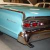
Hell yes! Yours has the spot timers which mine doesn't but the article number has now given the right search term to finally get a wiring diagram, epic! Thanks heaps!2 points
-
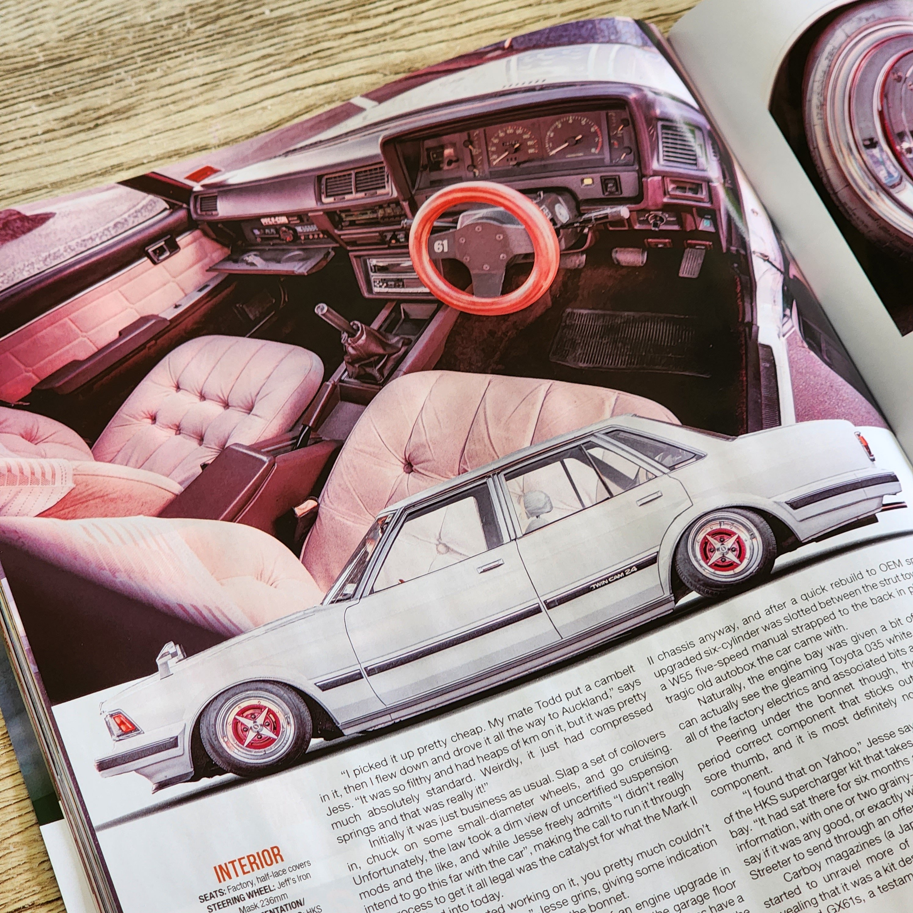
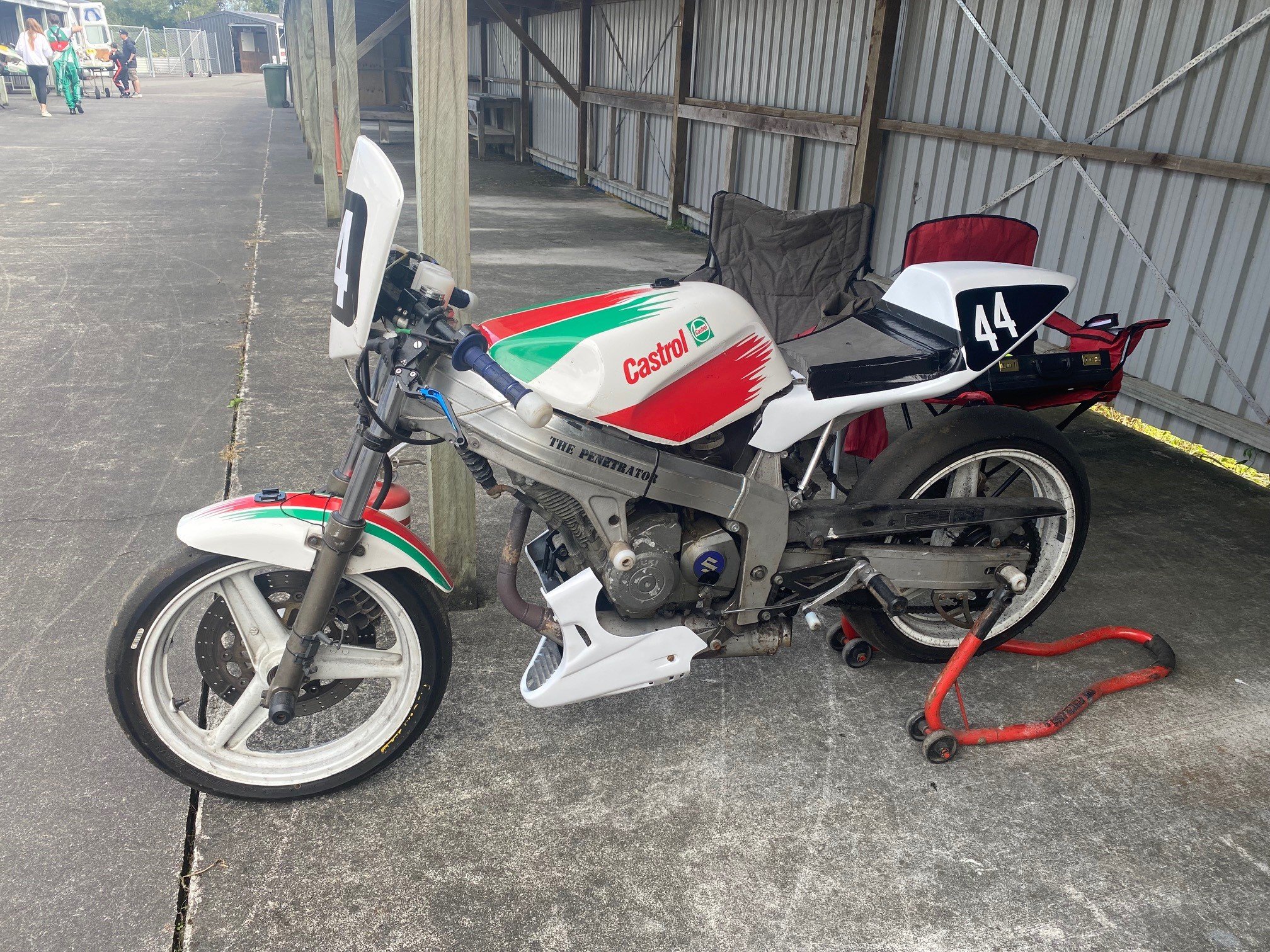
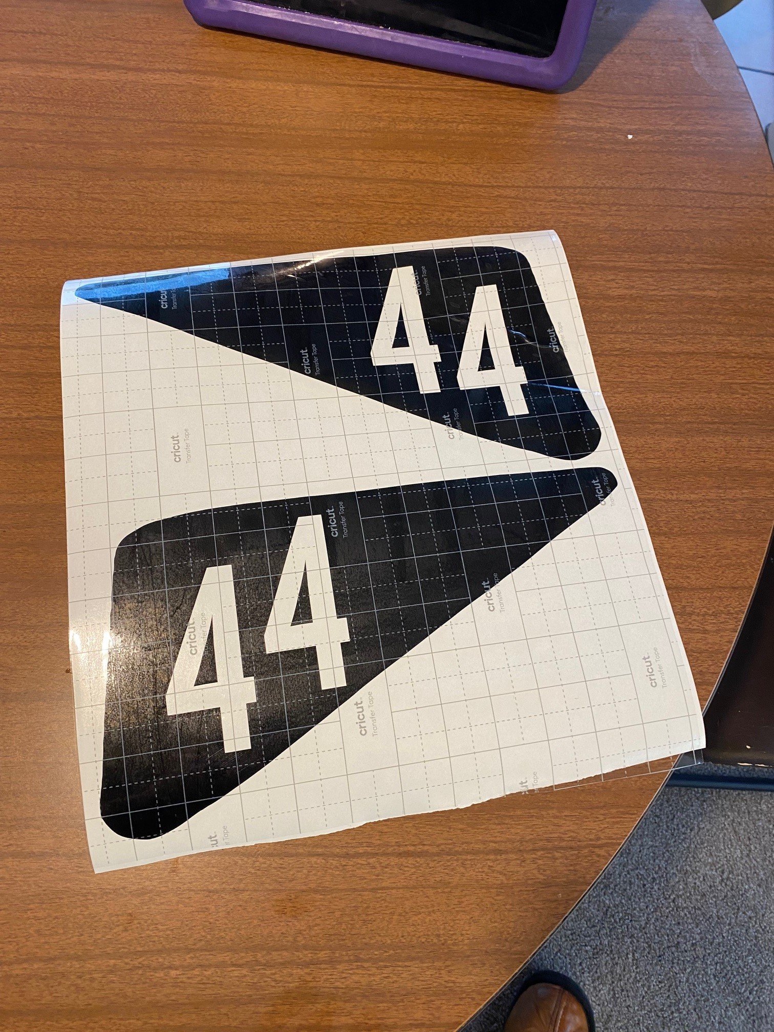
Long time no update. I haven't been riding much, just been busy with life. Still been involved quite a bit with stewarding etc though. The last few months I've made a real effort to get the bike out a couple of times, just done a couple of half race days along with my stewarding duties (which is ok cos I'm a bit unfit on the bike at the mo). One thing that has really been bugging me is how slow I've felt on the bike, I've felt very rusty and not confident, and as we have no timing, can't tell if I'm slower, or everyone else is faster. Back in my teenage years when I was racing Karts, I had an alfano pro, which measured rpm, lap times and head temp. The lap times were really handy, cos if you were getting clobbered, you could look at previous times and see that you are actually going as fast as you ever have, just the other guys are going even faster. I picked up an old one of these and have had it on my bucket bike to monitor the head temp when I had the 2-stroke engine, but since going 4-stroke, its only ever done rpm. They use a sensor to detect magnetic strips in the track for lap timing, and have to run pretty close to the track to pick it up, so I have never been able to make it work on the bike. I've been thinking for ages about how to try and mount it to work, and came up with this: Note the shiny new lower fairing (with sneaky lap timer hiding inside). Its off an RGV150, made up a few brackets and painted it white, and bobs your uncle, now I have lap times on the dash! I also re-painted the tail and made up some new numbers with my wife's cricut machine. I'll re-do the numbers as they didn't quite come out at regulation height, and as the steward I feel I need to lead by example, as much as I can't be bothered...
2 points
-
He’s quite right obviously. I’m pretty confident that this aspect is good and the initial measurements I did tended to prove it. Will re-measure more accurately before refitting and may even plot a graph….. Other thing is that I have had it working beautifully in the past ….. Even this particular collection of scrap worked very nicely when first installed. I’m coming to the idea that this failure was mostly due to crap parts.2 points
-
Just took this for its maiden voyage. Zero travel in the front . 50 percent of a exhaust. So bumpy and so rowdy. Love it . Still a shit load to do but darn it's a good feeling
2 points
-
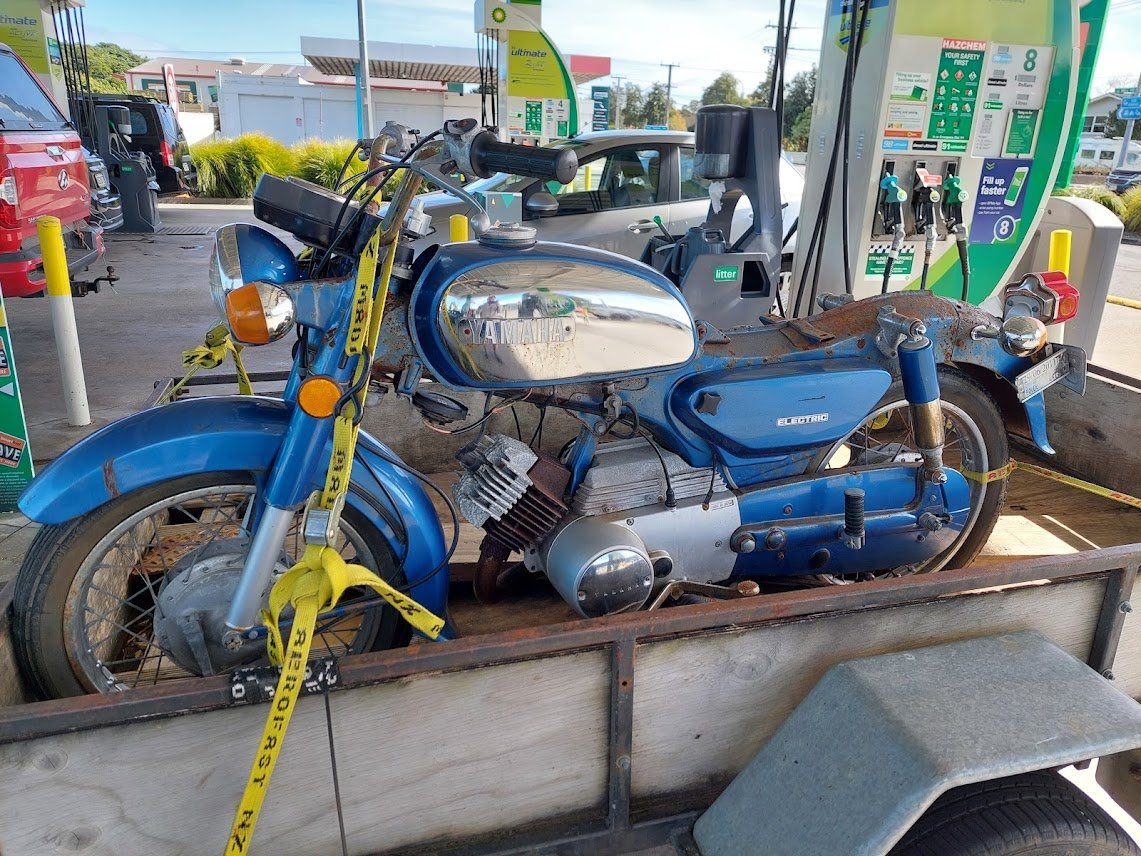
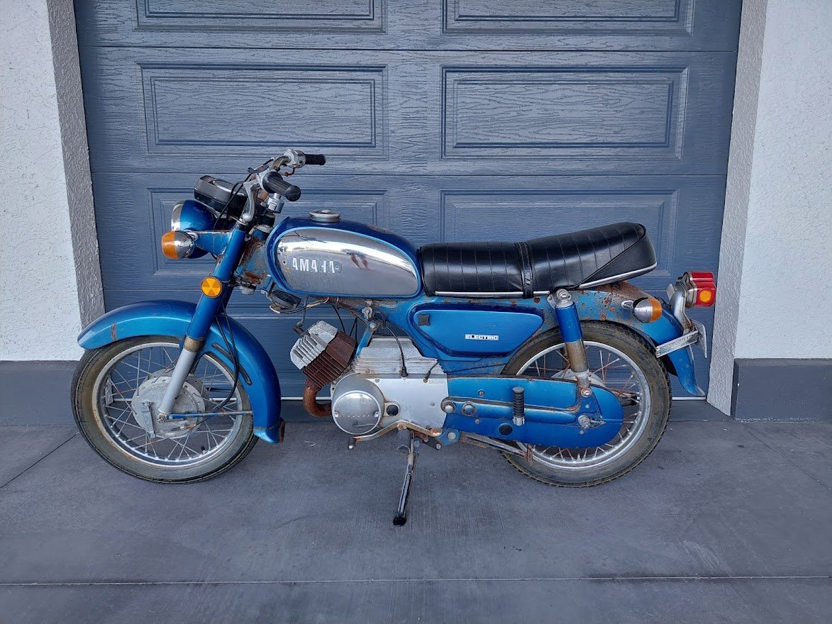
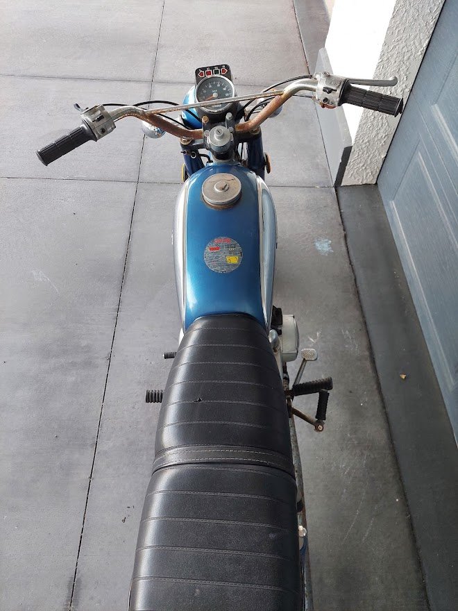
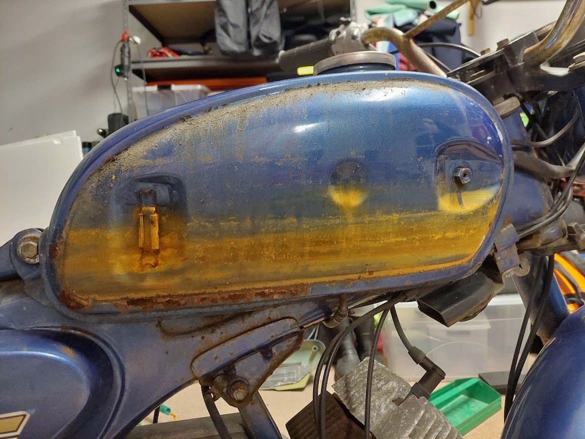
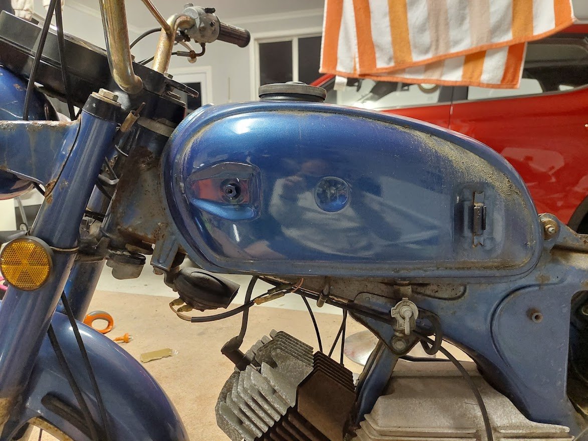
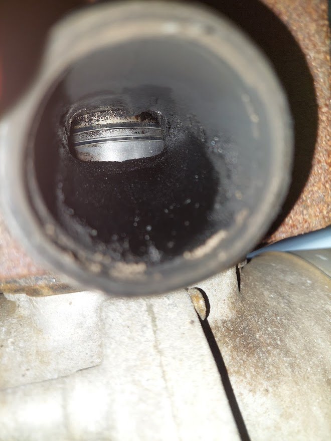
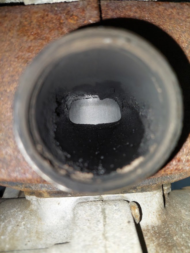
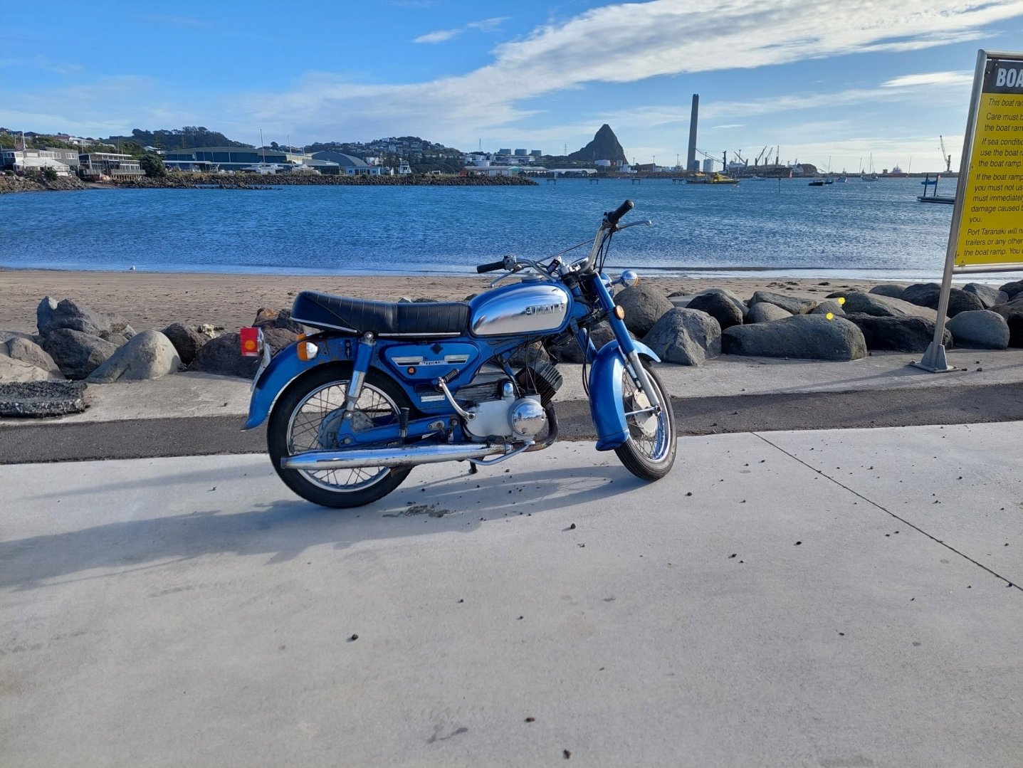
I recently got the urge to get a bike back in the garage and start enjoying that small bike life again. Was browsing up a storm on FB marketplace, trademe etc but everything seemed to be either too fucked, moonbeams or in the South Island. Sitting on the couch one night with the Mrs I got the notification that a 73' YB125 was closing soon. Had a few bids already but was still only $550 or so. Chucked a bid on, few back and forths with someones autobid "just to see how high it might go" and I ended up winning it for $590. Whoops . Supposedly a runner, but has been sitting for a while and the key is lost. Has been registered previously but lapsed. Got in touch with old mate, bike was in Wellington so organised to go down easter friday and pick it up. Borrowed @anglia4's trailer and he decided to come along for the trip too, legend. Early morning hoon down to Welly, bike on the trailer, back to NP by mid afternoon. Got it into the garage and started taking it apart to see what is lurking underneath. Lots of surface rust Grimey build up on autolube pump. Carb looks pretty good inside though? Managed to get the exhaust header off without much trouble. Rings and piston looking good to me so I probably wont bother taking the head or jug off for now. Things to do: I have taken the ignition off and given it to the local locksmith to see if he can cut a new key that fits. The petrol cap has a lock on it too so I haven't been able to get inside that yet to see what state its in. I've taken the petcock off and there's no fuel in there so hopefully no holes. My big idea is that the fuel cap and steering lock and helmet lock were all keyed alike to the ignition but just used 2/3 of the 4 pins (or whatever) so if I can get the ignition key cut then I don't need to bang a screwdriver in and wreck the petrol cap. Worst case there seems to be NOS ignitions with keys and petrol caps on ebay indonesia for acceptable $$ so I will get one of them if no bueno with the locksmith. Fingers crossed he can because I don't really want to wait for Garuda Airmail to be able to ride it properly! I've got a new battery coming too. This model is electric start too which is lush/not in the spirit of old 2T at all . Questions for the hive mind: unsure what I should do (if anything) about the rusty bits. My initial thinking was to do a quick wire brush of all the loose stuff that is out of sight on the frame under the tank, seat etc and then brush on some rust converter to try and slow down/stop whatever is left. Mixed reviews on effectiveness of that stuff though. Would that be worth it or a waste of effort? Better off hitting it with a wire wheel to properly get rid of it then spraycan/brush on some rustkill primer and closest colour matching topcoat?
1 point
-
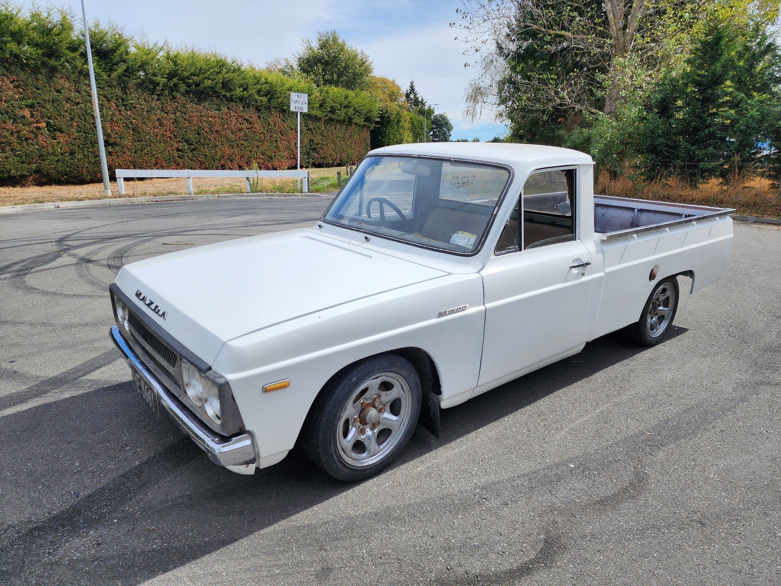
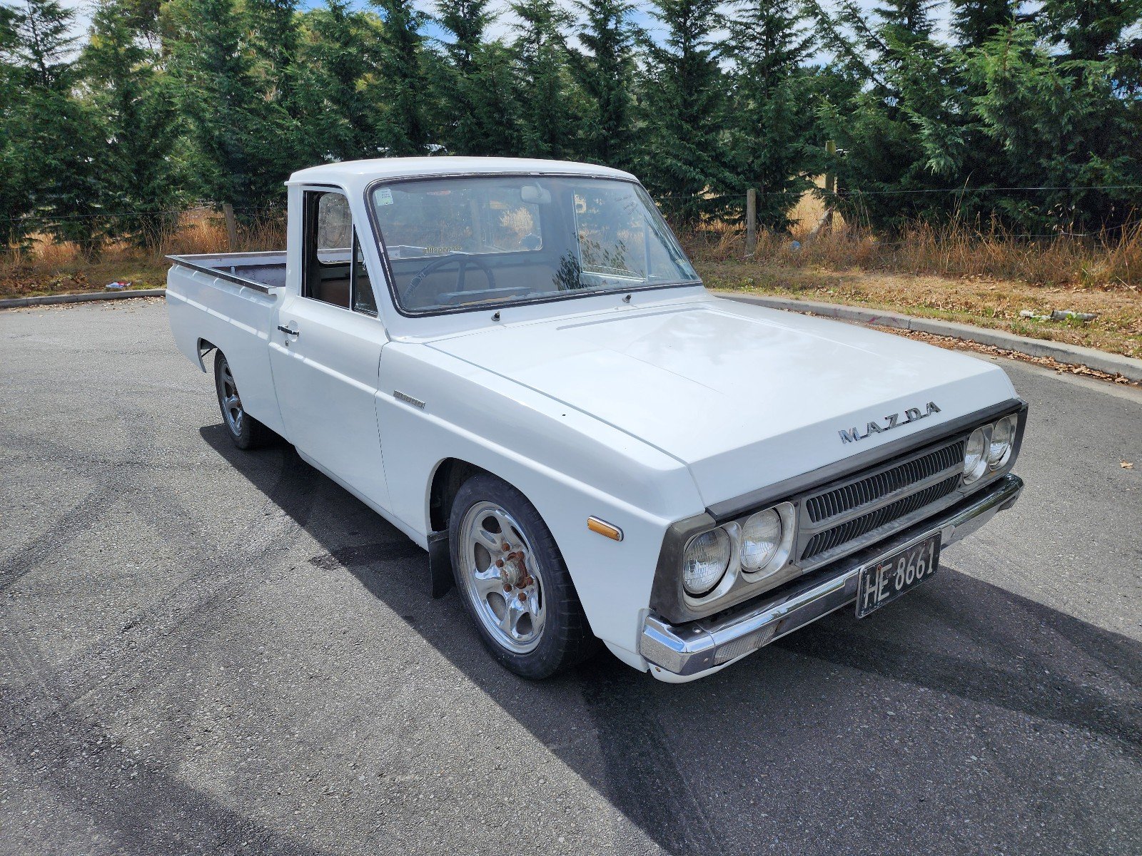
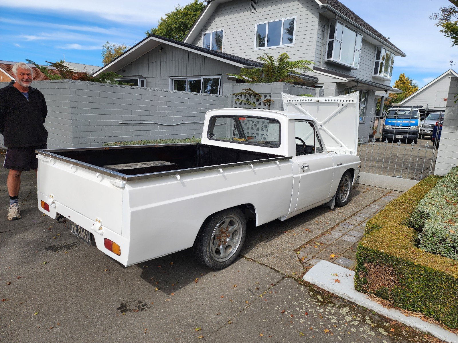
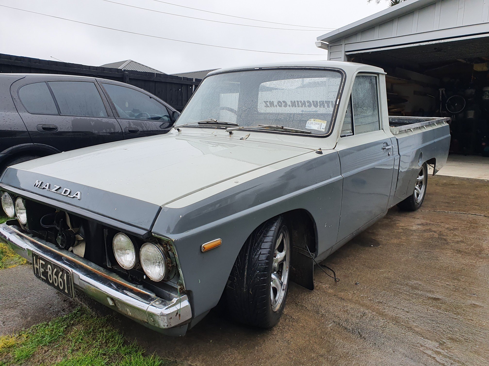
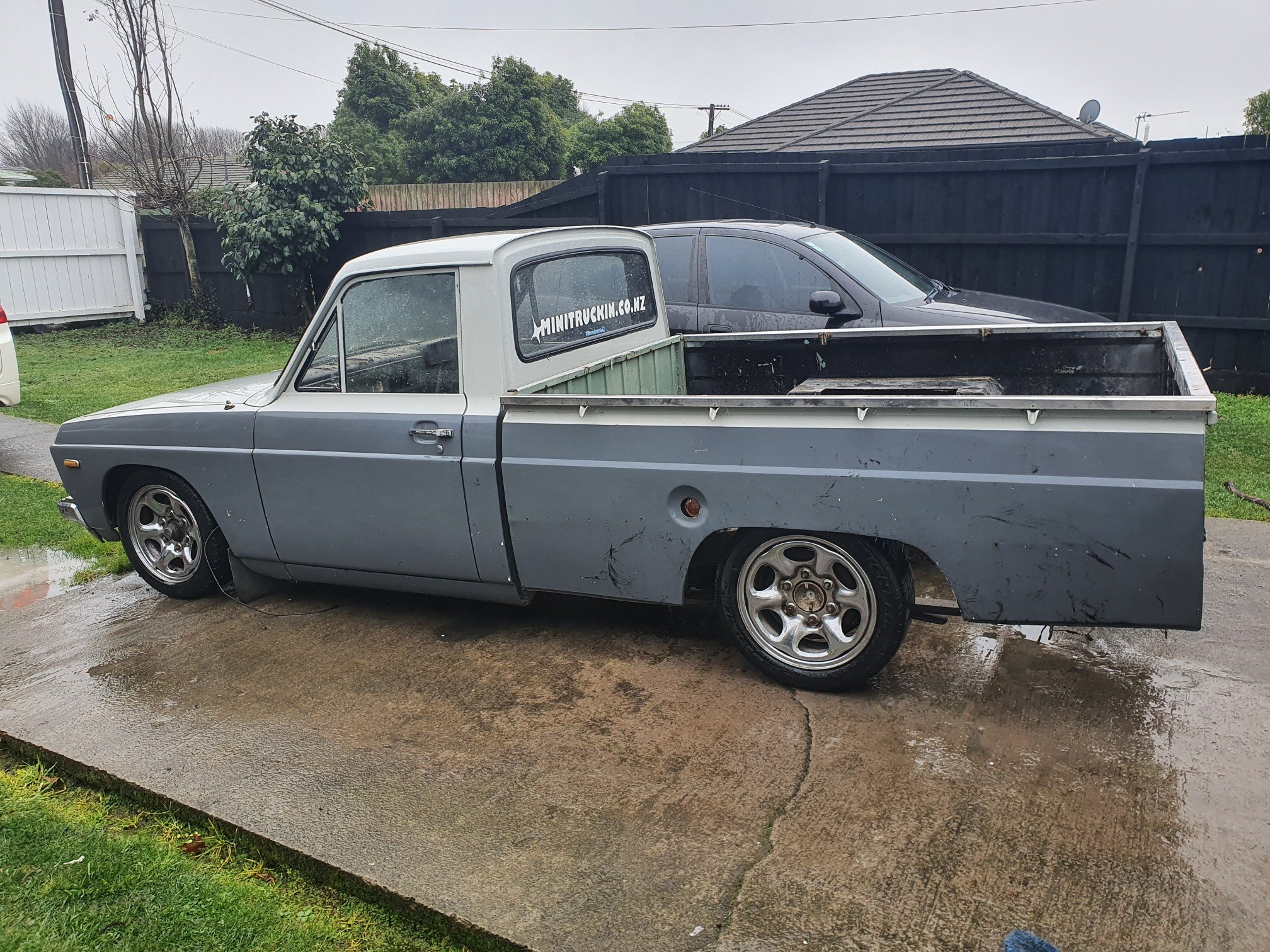
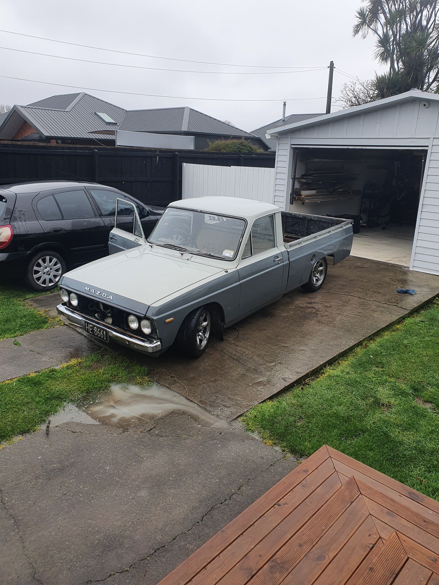
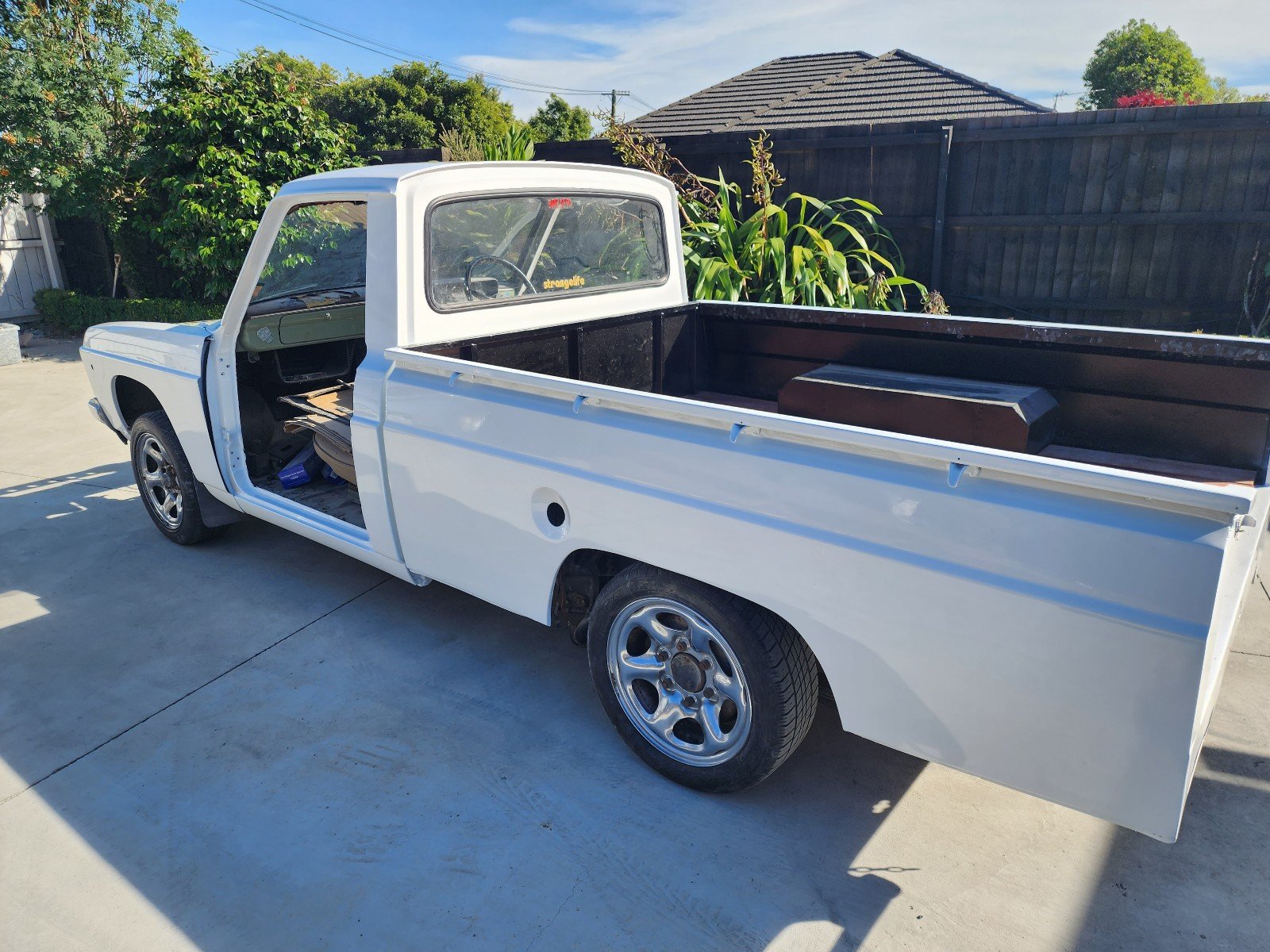
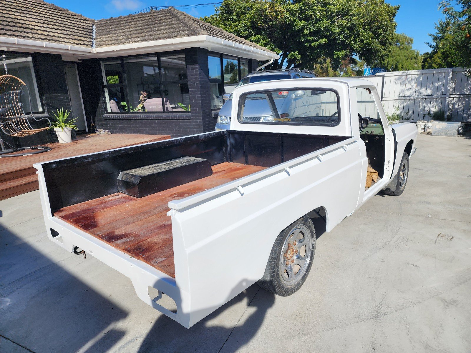
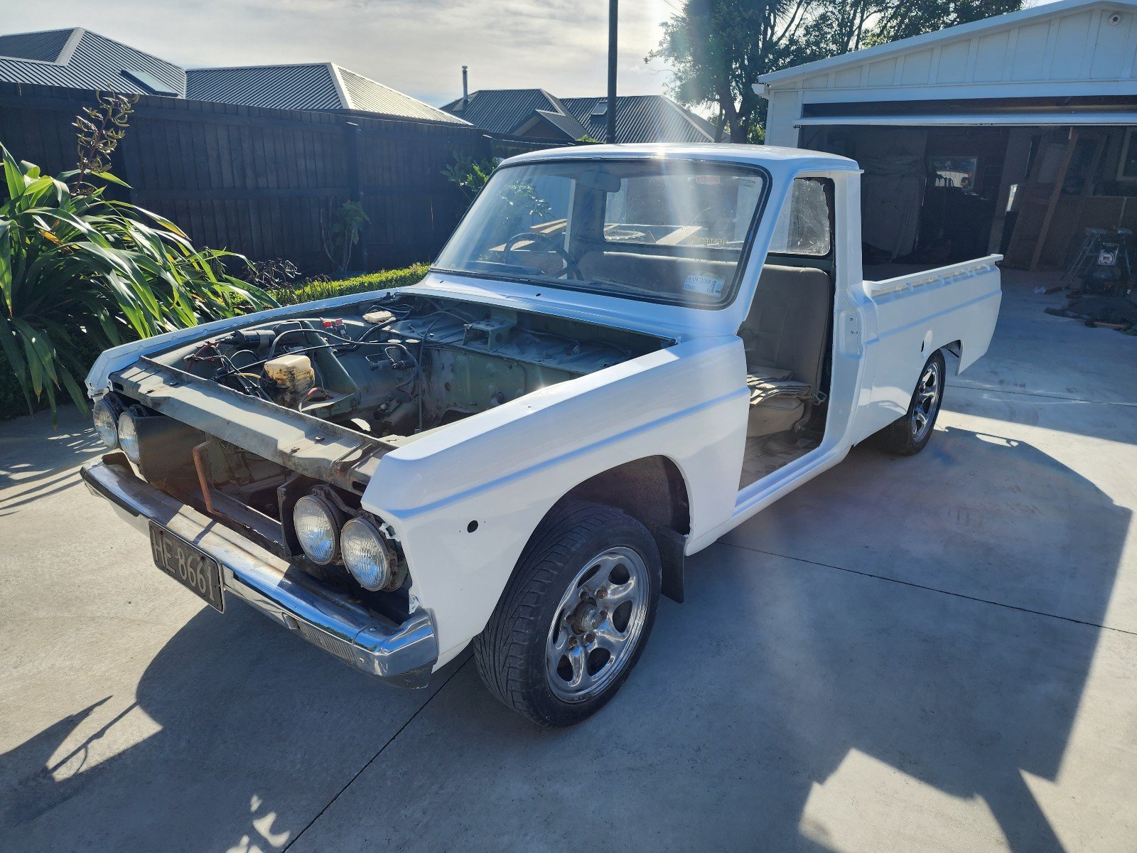
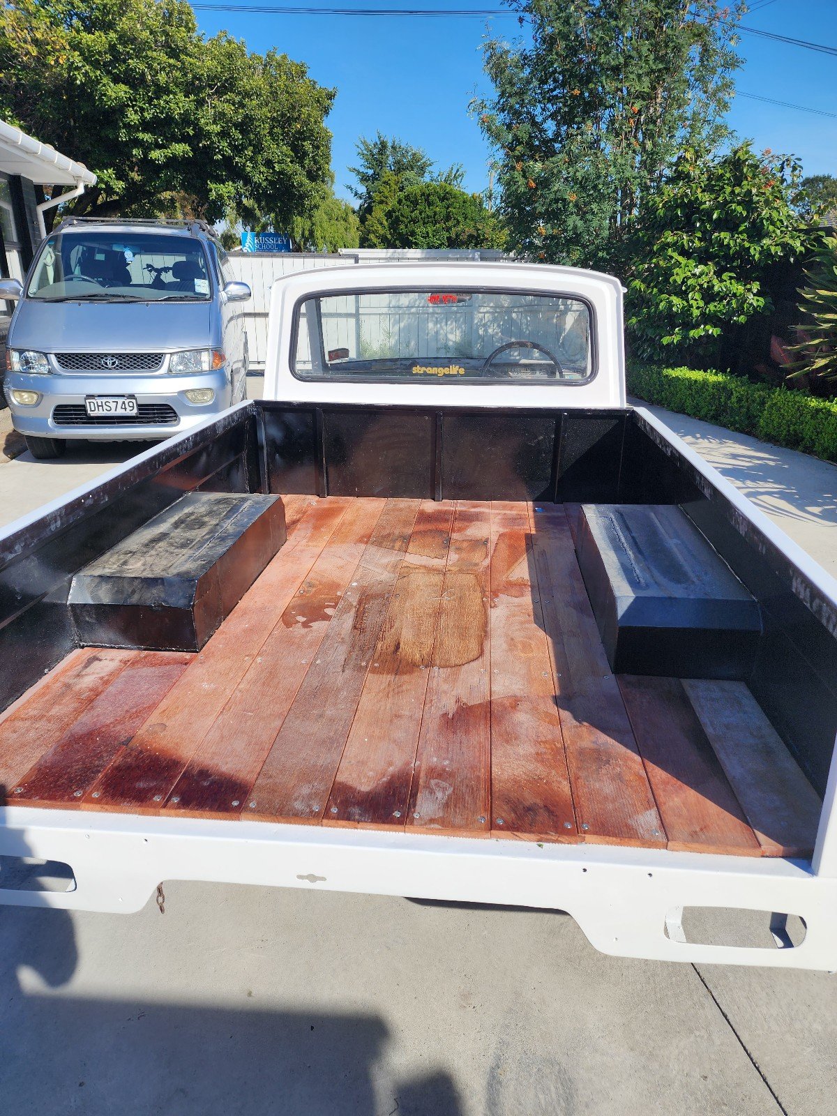
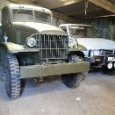
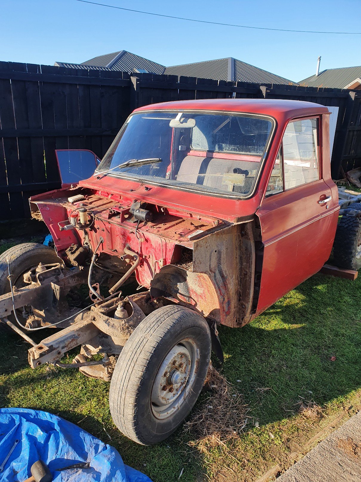
Just picked up this old girl off a mate of mine who had owned it for about 12 years. It's going to be a hell of a lot of work to get it legal ago. He built it as a bit of a skid hack and not alot else. Has a 2l in with with a bit of head work and a cam in it with a 5 speed box. Has been c notched which I'm not sire of i will continue down that route or hunt down a factory chassis . I've got the grill and head light surrounds to throw back on which should make it looks a bit tidier Anyway on to the pics Disco thread
1 point
-
Well I don't think this dudes earlier 1800 has the same troubles. It just keeps bouncing back! ( I reckon a 1500 would have had its cam belt housing/pulleys smashed) This fella Matt has some cool vids inc a nice offroad trip in Idaho back country on this bike.1 point
-
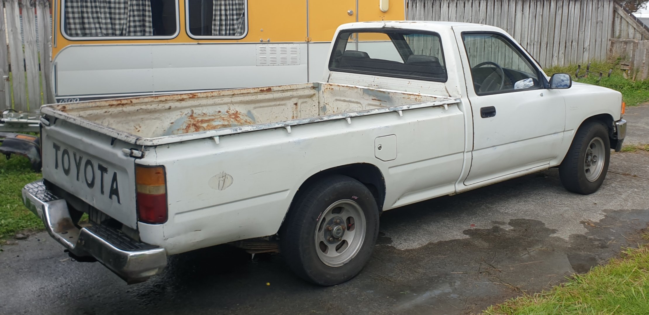
Toyota wreckers are thieves especially van/prado/hilux ones. Buy every single wreck at top dollar, corner market, print money. Around here anyway. Good luck1 point
-
Thought I had crossover pipe all sorted so did wee trial fit today found it ends up straight into sway bar mount. Fuck it re do it all. Turned out nice had a good few hours asphyxiating my self with argon loved every minute. Engine is now sitting at the perfect angle I can see it in garage from dinner table.
1 point
-
You can also have pretty wild voltage fluctuations with the ecu regs when they are on the way out. My commodore was all over the show charging voltage wise when the reg was on its way out but didnt throw any codes just noticed because i have a factory voltage gauge. Blairs auto electrical have a massive stock of parts was 120$ and i replaced the reg and rectifier for good measure was relatively simple just need a grunty soldering iron for the rectifier to the windings.1 point
-
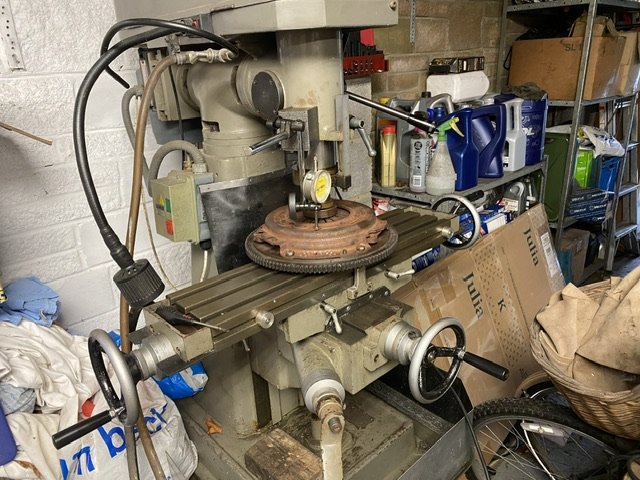
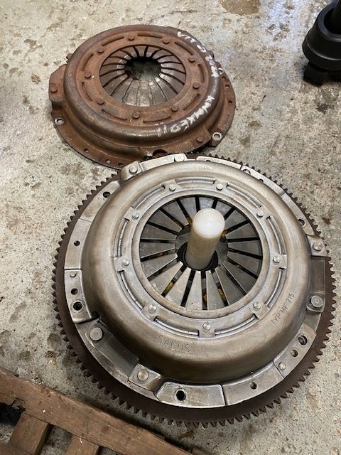
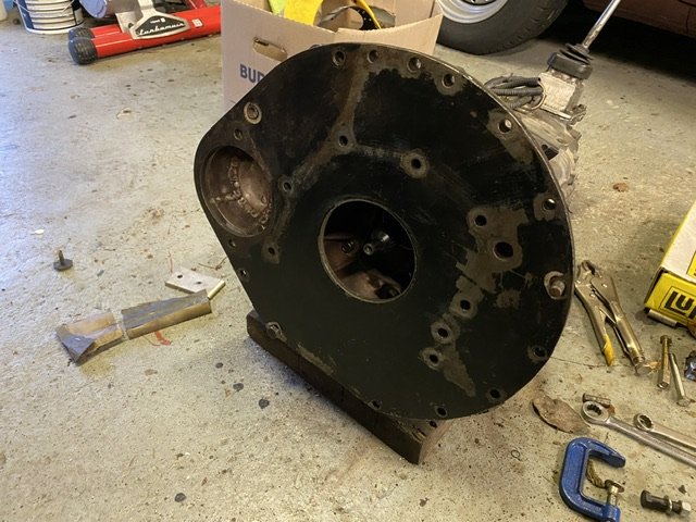
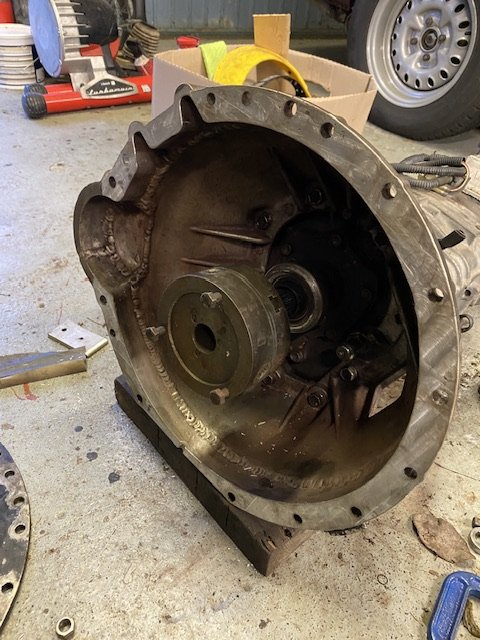
Update on this. Checked crank endfloat. 0.2mm. My build notes say it was 0.17mm when first assembled 28k miles ago. So that’s good. Did some testing using the mill That’s the combo that’s just come out. The friction plate is only about 1/2 worn at 7.35mm. It starts to release about 6.5mm but needs 8 to fully release as the spring has gone lopsided. That, with sticky splines will be the wide biting point I think. The same friction disc with my new Sachs cover starts to release at 3.5mm and is fully free at 4mm. I gathered up the wreckage and took it to my localish clutch shop. He was very polite, but I think he was telling me his competitors friction plate spline was made of cheese. No doubt on his thoughts on the QH cover…. Bin food (that was before I fitted it!). They made me a replacement friction plate in an hour…. And it was half the price of the last one. Top service! The new friction plate is 8mm thick and with the Sachs cover needs 5.5mm to start to release and is fully free by 6mm. Meanwhile, I put my hybrid bell housing on the mill. Engine side face was a little wobbly so I faced it. Took less than 1mm to clean. Fitted the backplate, flywheel and bell to my spare engine. Then posted the gear box in from behind. Spigot picks up in the pilot bearing first then the gearbox/bell dowels engage. Little bit of a wiggle and shove and on it pops. Alignment can’t be too bad. But to check another way…. pop the backplate on the bell and it’s very tempting to think that 4” (3.997” in fact) hole might be intended to be concentric….. but is it? Being both lazy and cheap I spent 10 minutes rummaging through my junk looking for a ready made tool…. Turns out I have this 3 jaw chuck which measures 3.993” and easy to nip onto the spigot. Pops right on, no wiggles needed. I think she’s good. Have also clocked the backplate on the mill. It’s a bit dished (0.5mm), but evenly so. Within 0.2mm. Better than my 2 spares…. Made an alignment tool Running out of excuses not to refit, except I tweaked my back a week ago and the refit is intensely physical…
1 point
-
Re dash lights, check your alternator and battery. Often when there are codes everywhere it causes by low voltage. A lot of modern cars will turn off the alternator when idling until there is enough electrical load.1 point
-
I wasn't expecting to buy another bike this week, but you know how it goes. An old man came into work and asked "How's your mates gyro going" referring to @Raizer sick rig, so obviously I'd mentioned it to him in the past. He then says he's going to sell his, so I had to go look at it. I then proceeded to fall in love. It's so hilarious. The dude I got it off was 76, and the previous owner was also an old man that got it for his import wife to use, but she never did. So it has quite a few old man spec "improvements" which include LED strip lighting riveted to the body with a crap ton of rivets. Paint "touch ups" which means badly applied rattle can paint with lots of over spray. Lots of random holes drilled in the body, every fastener they have applied is a different drive, and an oil line blocked off with a cupboard shelf support pin and copper wire. So she needs a bit of love and attention, but I was surprised to see it had aftermarket rear rims/tyres and an expansion chamber, so she might be making a few extra microwatts. Anyways, the new bike/trike is a 2001 Honda Gyro Canopy Wagon: Note method of light attachment, and modified floor mat, The lean over/hand brake lever has snapped off, so I need a new one of them. I'll also have to try clean up the windscreen, it's a bit messy. Phat tyres, rice pipe, and old man reflective decorations. The OEM lock is gone, has old man spec latch, will sort something better, Douglas racing rims, and sweet dice valve caps. 100% I'm going to redo the white lettering, Powerplant. Needs an air filter and a few mounts made for fuel pump and coil, plus a few hoses need replacing. The pipe is quite neat, I fucken love these rims/tyres TBH, It's totally getting vinyl stuck on the headlights to make JDM angry slantey eyes, The LED lights are coming off because the are horribly fitted and stick out like dogs bollocks, but I will probably refit them underneath and a more discreet manner. They have like a trillion settings too, So yeh, lots to do, but pretty excited to finally have a gyro. Regards, VG.1 point
-
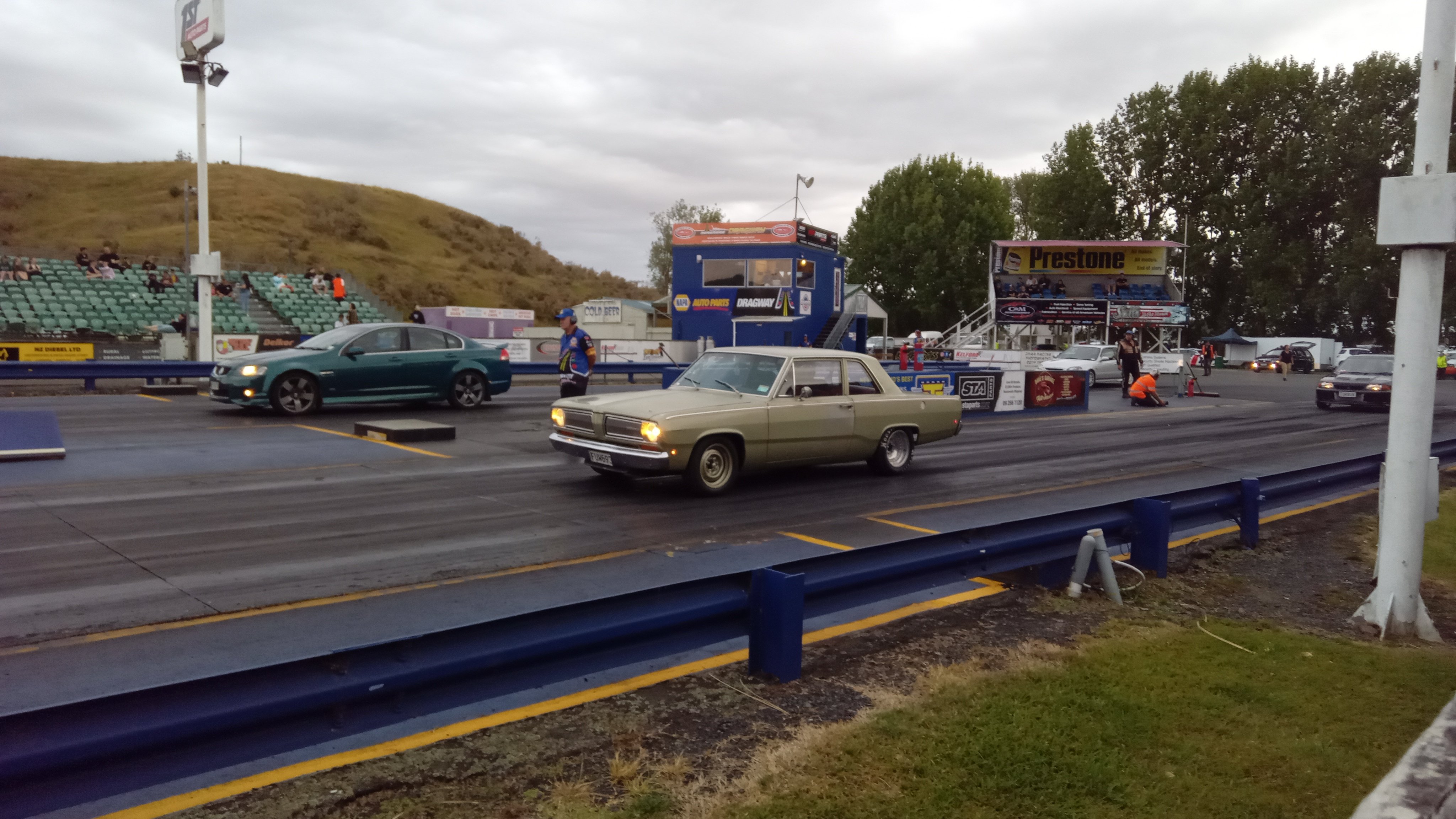
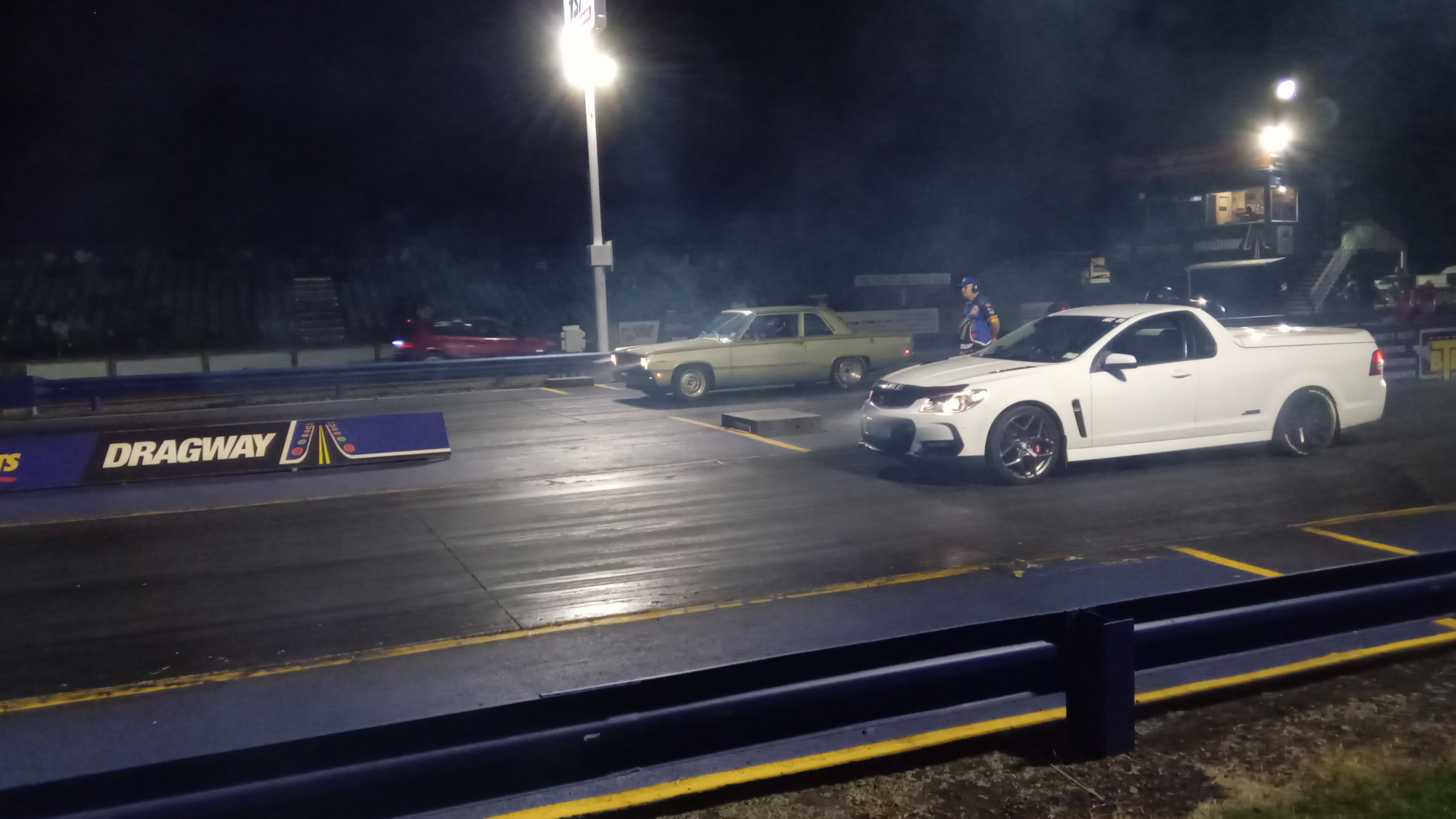
New springs made it more consistent,although slightly slower. Different wheels and muffler off when it did the 11.35 previously 11.5@118 every pass I have turned the 2 step rev limit down slightly as it was having trouble holding on the brake which I can probably fiddle with to improve I'd like to get it down to 11.0 so it's more competitive at the night drags https://m.youtube.com/watch?v=kdfGgT2pKHw&pp=ygUMVW5kZXJjYXJ2aWV3
1 point
-
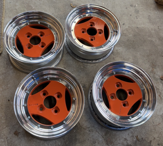
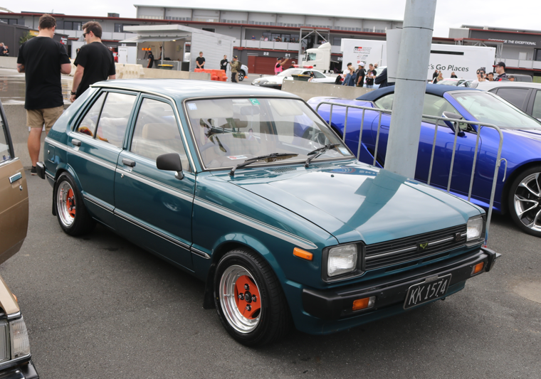
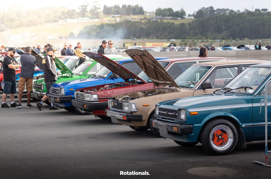
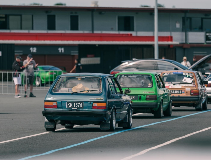
I have always loved Advan A3As and I managed to I pick up a set of 13x6s. I got the lips fixed, painted the centres and convinced the bro to polish them for me (not a member but cheers mate). Orange and blue is a sharp contrast, but it's grown on me Which brings us now back to first sentence of the previous post. I've just driven this from Wellington to Horopito to Toyota Fest at Hampton downs and back (1300 kms) with a couple of mates. There were a couple of small issues with the KP on the trip but those were quickly and easily rectified. It might be slow, but it got there ha } Have a squiz the oldschool.co.nz sticker I got over a decade ago and never used until now. That's all for now
1 point
-
I modelled and printed some door card clips which as always gives me the deepest pleasure. These worked pretty well after some tweaks. These are not exact copies and are designed so they are easier to print, but functionally they are sweet. The drivers side window winder mech was deeply wrong, the wire tension adjustment was maxed out, hacked and the maxed out again, but the wire was still as loose as fuck and while it kindof worked it made horrible grindy noises. This came from the barrel where the wire was straddling grooves cos it was so loose. It was all down in a difficult to reach place, and those mechanisms are notoriously cunty to pull out and put back. Amazing that I got a bollock into that shot as well. The passenger side was sweet and the wire connection looks like this; After a bit of thought and dicking around trying to take slack out of the wire a genius idea came to me; I routed the wire like that through both lift points, which took up enough slack that I could tension the mech properly. Another 1/4 hr of contortion with a torch, phone and screwdriver and I had the wire slipped back into its rightful track. It works perfectly again, yay!1 point
-
Bolted more shit on. I thought I had better reassemble the doors and check their function before chucking them on, and shortly I noticed that this little tit on the door latch had broken off, which would mean I would have to unlock the passenger side and reach over to unlock the drivers. See that tit on the diecast part? This actuates the lock from the door key; Commence bodging And it worked! I was quietly pleased with that as those latches are pretty much unobtainium these days Then I realised that I was trying to use the passenger latch in the drivers side, so that was all a waste of time. Except that the boot and engine cover latch levers are in the shut off of the passenger door. So actually it will be pretty useful to be able unlock the passenger side to get to those. I seem to recall this not working previously. So fuck all left to do really; Windscreen Box on and engine in Final wiring connections in the engine bay once the engine is in Passenger door Boot and engine cover Carb tune I am assuming the brakes will probably need rebuilding, we will just have to see. And whatever other fuckery arises.1 point
-
Old rubber lines swell up inside and act like a 1 way valve. I had this on the rear line on thr morrie, was letting the rears stuck on1 point
-
Progress is coming thick and fast now. Motor back in . Gearbox back in . Got it running today for a short moment. Seems to run like a champ. Waiting on a new waterpump then I can get it up to temperature.
1 point
-
Removed the tow hook the other day and fitted the blanking panel. The towhook will remain in the boot once I have the insert to store it. It tidies the front up a bit, but i do kinda miss how it looked. On a side note, now that the auction results have dropped off the system, the rusty 4WD Alto I bought in Japan has resurfaced at a dealer in Japan for a shade over a million Yen (more than I paid). Looks like they gave the underside another coating of underseal, and fitted the white "summer" wheels, which were missing from the car when it was inspected after I bought it...1 point
-
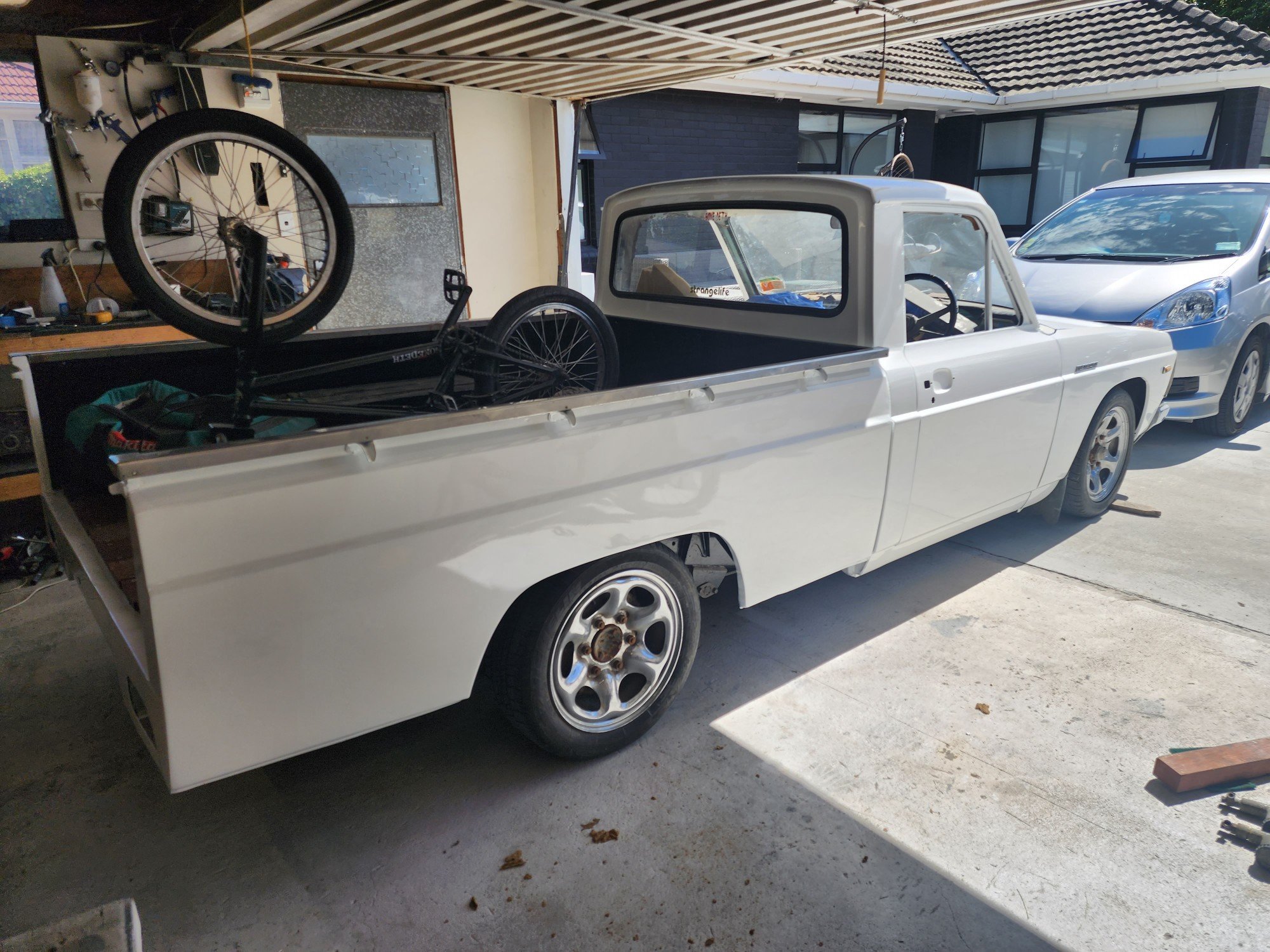
Bit more progress. Got doors and bonnet painted. Have slapped it together for some inspiration. Most panels need to come back off. Have started prep on engine bay and hope to have that painted in the coming weeks Damn it feels good to be making some progress after it sitting in the way for so long. If anyone has any leads on a 2l MA motor flick me a message
1 point
-
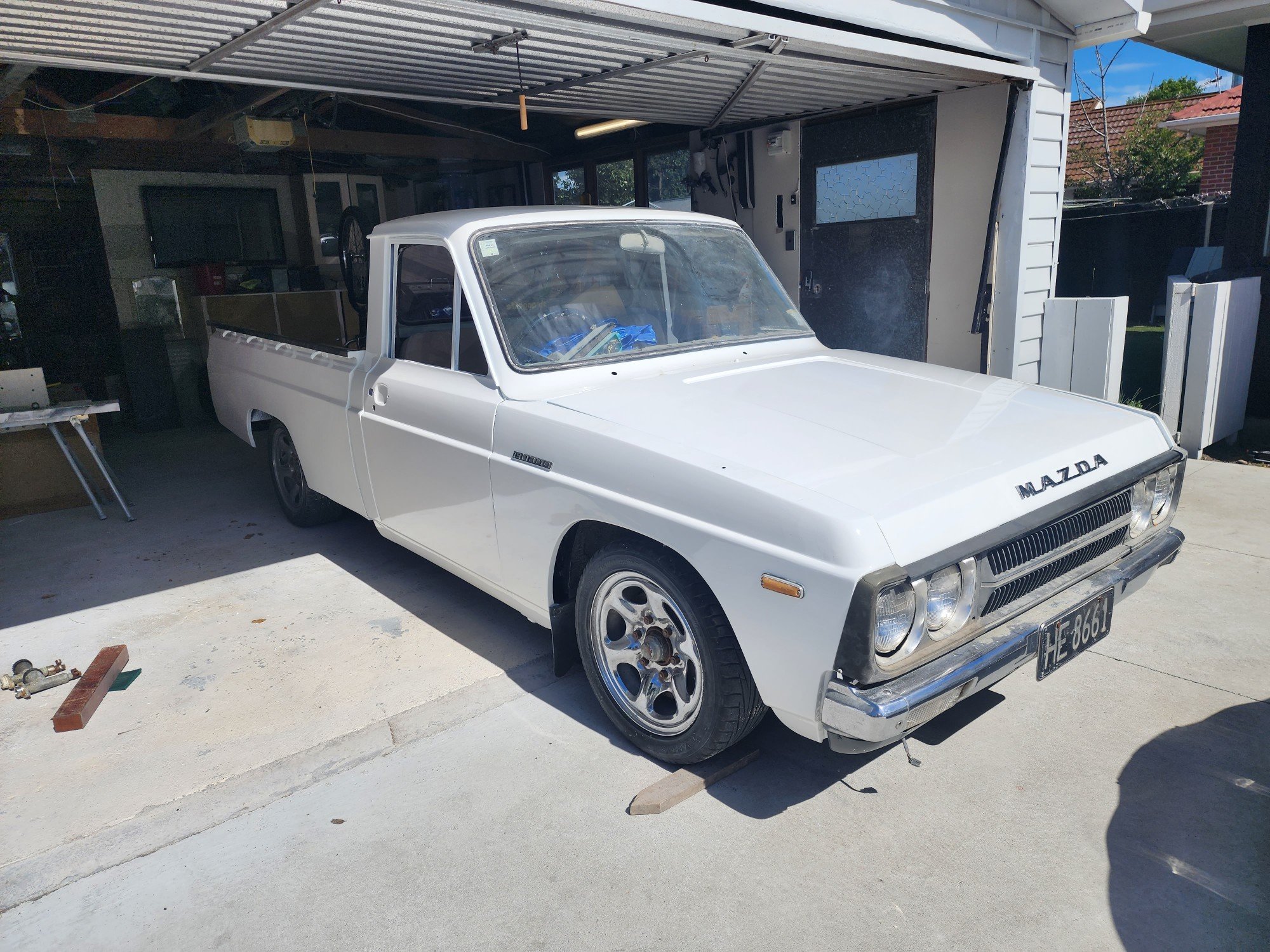
Took the angry little nugget to Cars and Coffee today. Got heaps of attention. Love it when people pass me trying to work out what it is, since it's devoid of badges on the back.
1 point
-
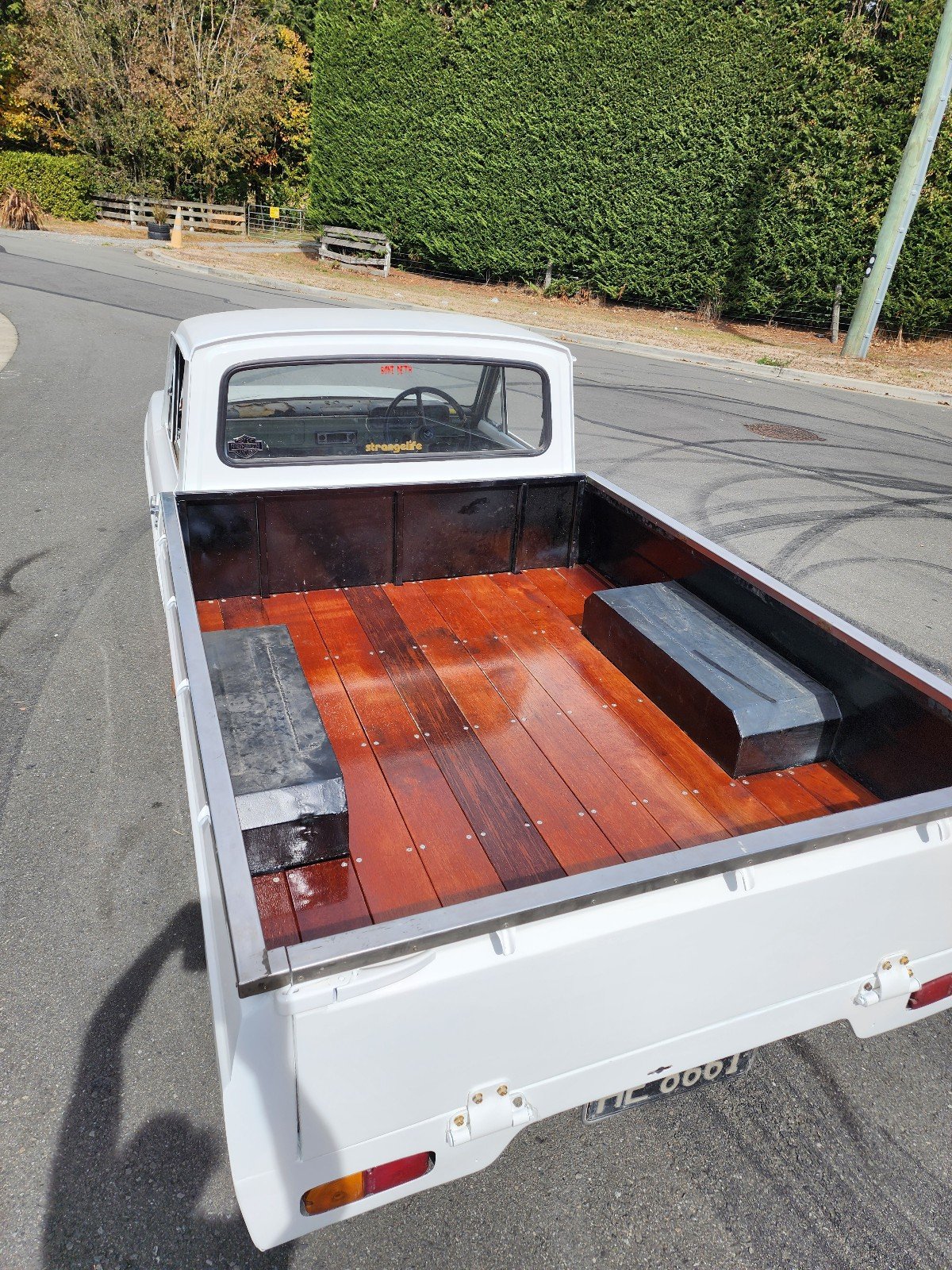
Thread dredge from a million pages back. I do still have this . Went hard over the holidays and got a few panels painted. Made a start on the deck ages ago. Still a bit to finish off.
1 point
-
Thanks @kws for your updates on your projects - always well written and great pics.1 point
-
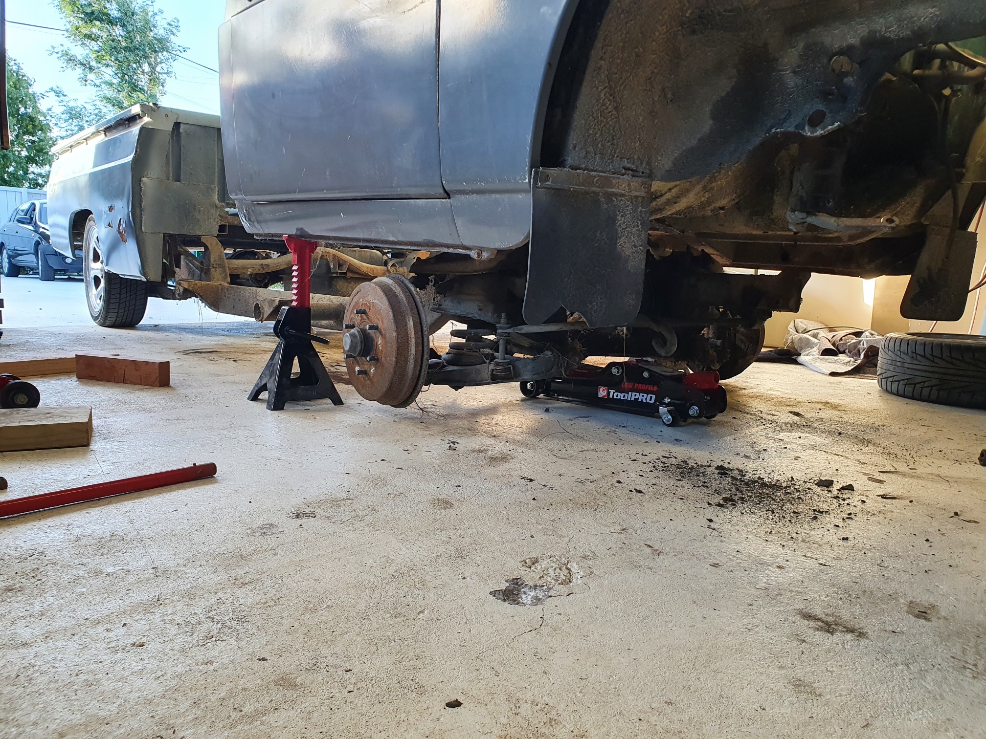
More parts arrived, so with some time up my sleeve this weekend I got cracking on fitting them. There were some checks to do before getting into the "fun" stuff. I had noticed while driving the car to work last week that there was a knock from the front suspension, particularly when turning or going over a bump, so I wanted to spanner check the suspension and make sure everything was tight. I found out last time I needed to jack the car up that my jack didn't fit as the front lip was too low, so I ended up having to drive the car up on a pair of old brake rotors to get some extra clearance. I decided this time it's about time I finally forked out and bought some low-rise ramps to help jack my cars up. A quick trip to Repco got me these They only lift the car 65mm, but it's more than enough to be able to get my jack under and lift the car up onto stands. Way easier than using random bits of wood/junk from the garage. The only thing was that I had to hold a mirror out the window to spot myself, and make sure I didn't drive off the end (not that it would matter, unlike big service ramps, these wouldn't hit anything if you drove off them). Rolling around under the car, everything appeared tight, until I went to check the lower balljoint on the RH swaybar link and noticed it clicked. Looking further into it I could see the top balljoint moving in the shock, causing the clicking noise. It turns out the nut was finger tight, and this was because someone had rounded out the hex in the end used to stop it from turning, so it couldn't be done up tight with a spanner. I whipped the wheel off for more space, and hit it with the rattle gun to great success. Nice and tight, and no more clicking. It pays not to ignore noises. One mod I had been waiting to install was my new-to-me Trust Greddy intercooler. The standard intercooler is tiny But before I installed the new intercooler I wanted to check the intake temps and see how both intercoolers react. With my headunit running native Android I can run TorquePro on it. This allows me to read a bunch of different sensors from the engine, including coolant temp, intake temp and even the factory wideband O2 sensor. Ignore my reflection and ugly layout; the layout is just thrown together quickly to display the most important stuff I will need on the track at a glance. With the standard intercooler, running 14.7psi, and an ambient temp of about 18c, under sustained load, the intake temp would rise quickly and hit about 50c. This would slowly drop back once off boost again. Not great results. The Greddy intercooler is a beast. It includes a new, much bigger shroud on the top, which fits the standard intake hose. Removal of the old intercooler is quite simple. Four (unless you're missing one) clips secure the shroud, two on each side. The intake hose just pulls off the shroud. Remove two hose clamps, one at the front of the intercooler and one under the rear, and then two bolts on the front of the intercooler hold it to a bracket. With those removed, the intercooler pulls free. Side by side with the new intercooler, and it's a slight size difference And in thickness too The previous owner had modified the stock intercooler, with something that Google translates as "processing", which means removing the end tank and insert crushed bits of alloy tube between the core tubes to try and smooth air flow on the hot side of the intercooler It turns out some of these had come free in my intercooler and were sitting in the end tank Thankfully they appear to be accounted for and are on the inlet side of the intercooler, so couldn't really go anywhere The new intercooler just bolts straight into place I noticed when test-fitting the shroud that there was a large gap along the rear edge, where air could just freely escape instead of being forced through the intercooler. I decided to run a bead of non-setting butyl tape along the gap to seal it against the shroud The standard intake and carbon duct work nicely with the new shroud While in the area I also replaced the hose blank where the BOV used to go on the intake pipe, as this was showing signs of cracking and had been weeping breather fumes Now done in the engine bay I moved on to the interior. I had ordered brand new carpet from Japan which arrived the other day, so no time like the present to get it fitted. It arrived in a massive box, which barely fit in the back of the Alto. Thankfully, it weighed nothing. Barely a kilo. The first job was to clear the interior out. Remove the seats, the center console and the scuff plates. The seats come out easily enough. Four torx bolts on each. Slide them to the mid position on the rails, and (un?)recline them forward about 45 degrees. They will then easily fit out the front door openings. Remember to disconnect the connector under them first. I didn't need to remove the back of the rear seat, just the base squab. A sharp tug on each front edge will disengage the front tabs, and then there is a tab on the rear that goes over a hook on the back of the seat belt buckle bracket, you need to push the squab towards the rear of the car to disengage this (or as I did, fold the seat back down, reach under it and lift the tab off the hook by hand). The center console is a pain. The rear half is held in with two bolts into the floor, one under a cover at the rear, and one that is uncovered once the front half of the console is lifted up. The front half is held in place with a screw on each side and is clipped to the rear half. The catch here was that it would be easier to remove the front half completely. To do so you would need to remove the gear knob. Suzuki used a press-fit knob on these, which I couldn't get off. Instead, I undid the four screws that secure the gear boot to the center console, which let me remove the console without the knob or boot attached. There is also a section in front of the gear shifter that needs to be removed. This has one clip on the RH side, and then a quick sharp tug should disengage the clips holding it to the center stack on the dash. With those removed, I set about giving everything a real good clean. I vacuumed up all the excess dust and dirt from the panelbeaters, and then gave everything a quick wipe down with APC and a cloth. From factory, the Alto Works had an underlay under the carpet. I wanted to replicate this without having to buy the pieces from Japan. Thankfully I still had a large part of the roll of underlay from when I did the carpet on my TVR After some quick measuring and some cutting, I had four pieces to fit Some trimming is needed to get them around the seat mounts, but otherwise they just sit in the footwell. Just like factory. Both sides had the same treatment Next, I unboxed the carpet and carefully dumped it in a heap in the back of the car After MUCH faffing about fitting the Monstersport foot rest, and poking holes in my new and expensive carpet, I refit the console and suddenly it looked a bit more like a car again. Don't forget to pass the seat plugs through the carpet! It tucks nicely under all the side trims There were two clips under the drivers seat, one clip under the rear seat, and one screw on clips on the front corners of the carpet. When refitting the front scuff trims I decided to remove all the faux carbon wrap they had on them It may have looked nice when new but was looking a bit tatty and dated now Thankfully once removed it uncovered nice near perfect condition trims. Much nicer (look for it in the below photos). I gave all the seats a quick vacuum as they were all also quite dusty, and then refit them So how does that flash new carpet look? Much better. It's practically a luxury car now. I have a set of carpet mats on their way from Japan, but until they arrive, it is brown paper time. Don't want to get that new carpet dirty now! Driving the car to work today had a few results; Firstly, the suspension knock. Gone. It is one of those things that must have been worse than I noticed because the noise is very conspicuous in its absence now. Secondly, the intercooler. The bigger volume hasn't affected response, if anything, it feels like it spools a bit quicker, maybe less restriction? Temps have dropped. Doing the same sustained high boost pull with similar ambient temps results in a 5-10c decrease in max temp, but the drop when coming off boost was much quicker, it was dropping degrees a second, so it not only cooled the intake charge better but shed the excess heat much quicker. Hopefully that keeps the intake temps in check on the track. Lastly, the carpet. Road noise is significantly decreased, as is exhaust drone on the open road. The exhaust might be more bearable at 100kph now since the car isn't acting as a big echo chamber. The car feels more civilised in general. It's funny how just refitting carpet can make such a big difference in how much of a "car" it feels. A+ changes. Very happy with how the Alto is coming along. It's less a track monster, and more a weekend warrior now, but much nicer to live with.1 point
-
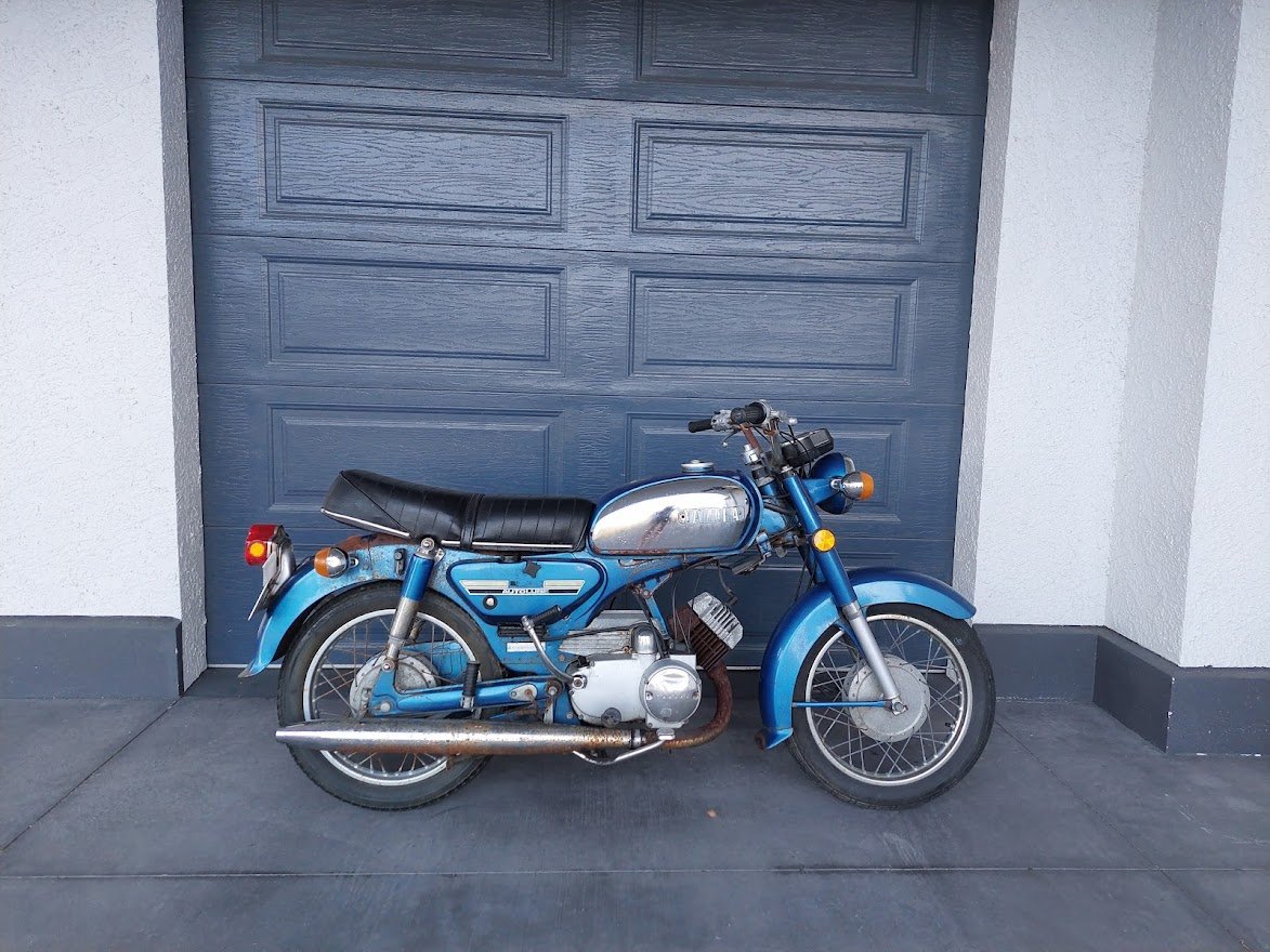
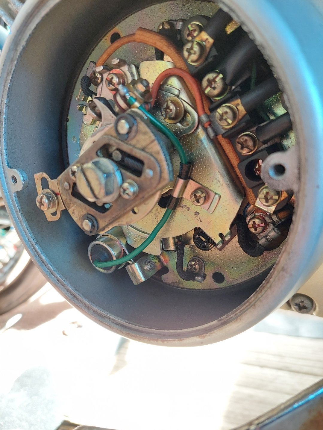
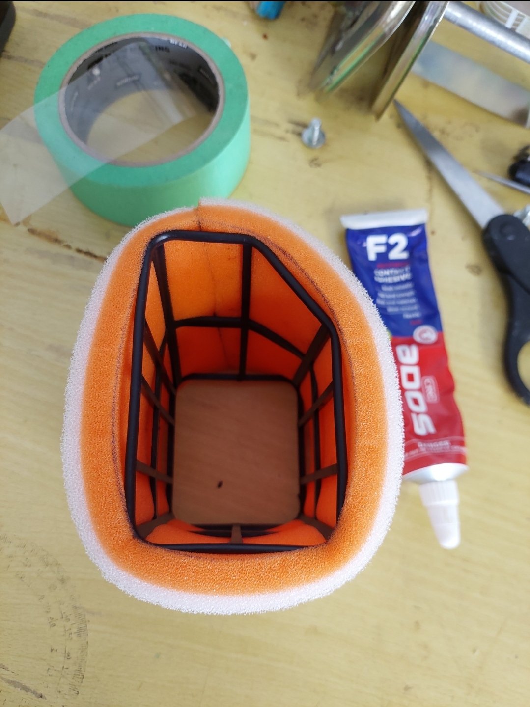
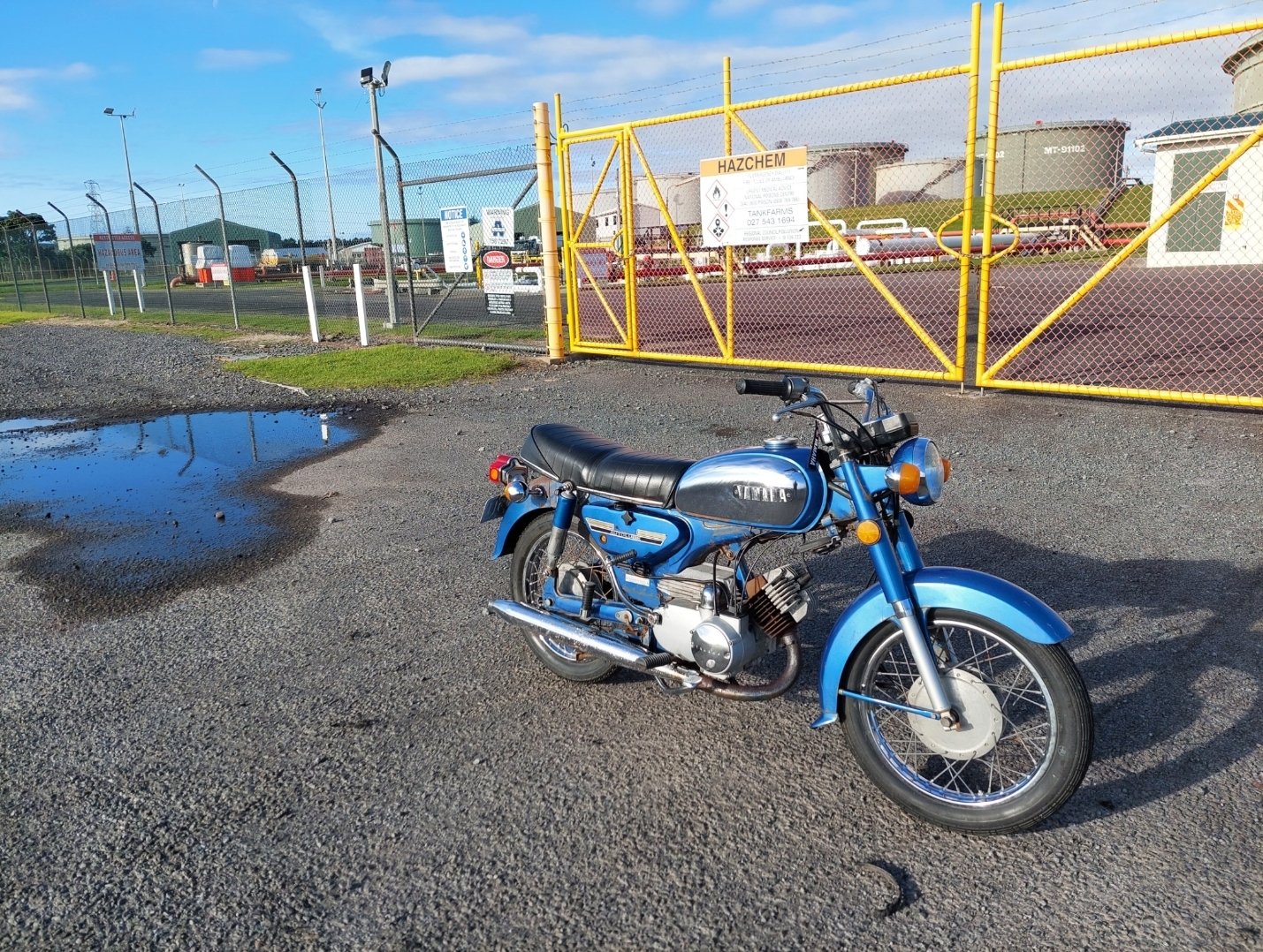
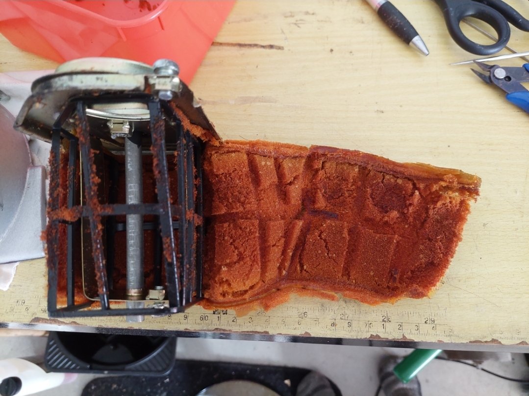
I put everything back together, splashed some oil and petrol around the various tanks and wheeled it out of the garage to go for a first ride. Wouldn’t start :haha: Checked spark (ok), fuel (flowing freely through line from tank), pulled carb and checked jets (all clear, fuel in bowl). Put everything back on again. Lots of kicking, coughed a couple of times, some backfires and eventually it fired up and idled for not very long before dying. More kicking and got it started again, turned up the idle speed screw so it wouldn’t die. Jumped on, rode up the driveway and down the street for a few hundred metres and of course it died when I slowed down to turn around and come back home. Absolutely would not fire this time so I had to do the push of shame home. I suspected electrical problems (likely condenser?) as fuel is there, carb is clean and set to factory specs and the electrics are 50 years old. It looked like quite a bit of pitting on the points surfaces so maybe the condenser wasn’t condensing properly and it was arcing across the points gap instead? I sanded the points smooth and reset the gap.There is f-all info on the YB125 on the internet for parts numbers etc so for anyone from the future looking for a YB125 condenser, the RD250/350/400 part 1A0-81625-10 is close enough to be correct. Capacitance, size, mounting and spade connector is identical, just the lead is a few cm shorter but still fits ok without stretching and too tight.. I got one from eBay from a seller in France. New plug, new condenser, fingers crossed? The muffler - header gasket was missing and the header/barrel gasket was pretty beat up. There was quite a bit of exhaust leaking out from the muffler joint. Again, nothing online that I could find for a “YB125 muffler gasket” and the part for its more common predecessor YA-6 is NLA everywhere. I did some measuring and trawling through other yamaha parts and the stock replacement for 70s XS500/XS650 371-14714-03 looks identical. These appear to be readily available which is nice. Order from PlenterNZ arrived with one of each, fitted the header pipe back on and tightened everything up. The air cleaner foam has gone rank and started disintegrating. Again stock replacements don't exist online that I could find so rather than making the engine inhale chunks of foam I ordered a replacement sheet of filter foam and cut to size and glued together to fit the cleaner housing. Oiled up and reinstalled. Everything back together and started up 3rd kick! Fiddled with the air screw and idle adjuster to get it sitting at 1200 rpm as per shop manual, checked with a cheap AliExpress hour meter/tacho. Its happy as. Took it out for a decent ride around NP, went great. Brakes are quite rubbish but work, got up to 80kph on the flat without speedtuck. Neutral top gearbox is wack, I have to think about each shift but I'm sure I'll get used to it. Got props from an old lady walking her dog when I stopped for a photo "now that's a proper motorbike" Time for more riding to see what else breaks before I start the re-registration process.
1 point
-
Right. It's bloody finished. Stupid shiny staff car didn't make the cut due to being over complicated and beyond my skill level. Found a Panzer IV in a box so on it went. Anyway, that'll probably be it for me and plastic until the winter. Far too nice out. / pics1 point
-
Nearly there. Think I'm going to need to spend some time on real cars for a while, this fiddly stuff will drive you potty.1 point
-
I just looked through all the packaging and there is not one mention of Mercedes, though a pointed star is included. Copyright avoidance ? / crazy fucken Ukrainians1 point
-
dunno, but it must have machine guns, theres sights on the hood1 point
-
I spent a while googling trying to win your one million pound prize to no avail What company manufactured that vehicle? I've never seen one before1 point
-
Getting on the cargo, gonna be a while till it's done though. Messing about with real cars again so don't hold your collective breaths. / Oh, you weren't.... The bare chassis will turn into this...1 point
-
Photos too big for 1 post.
1 point
-
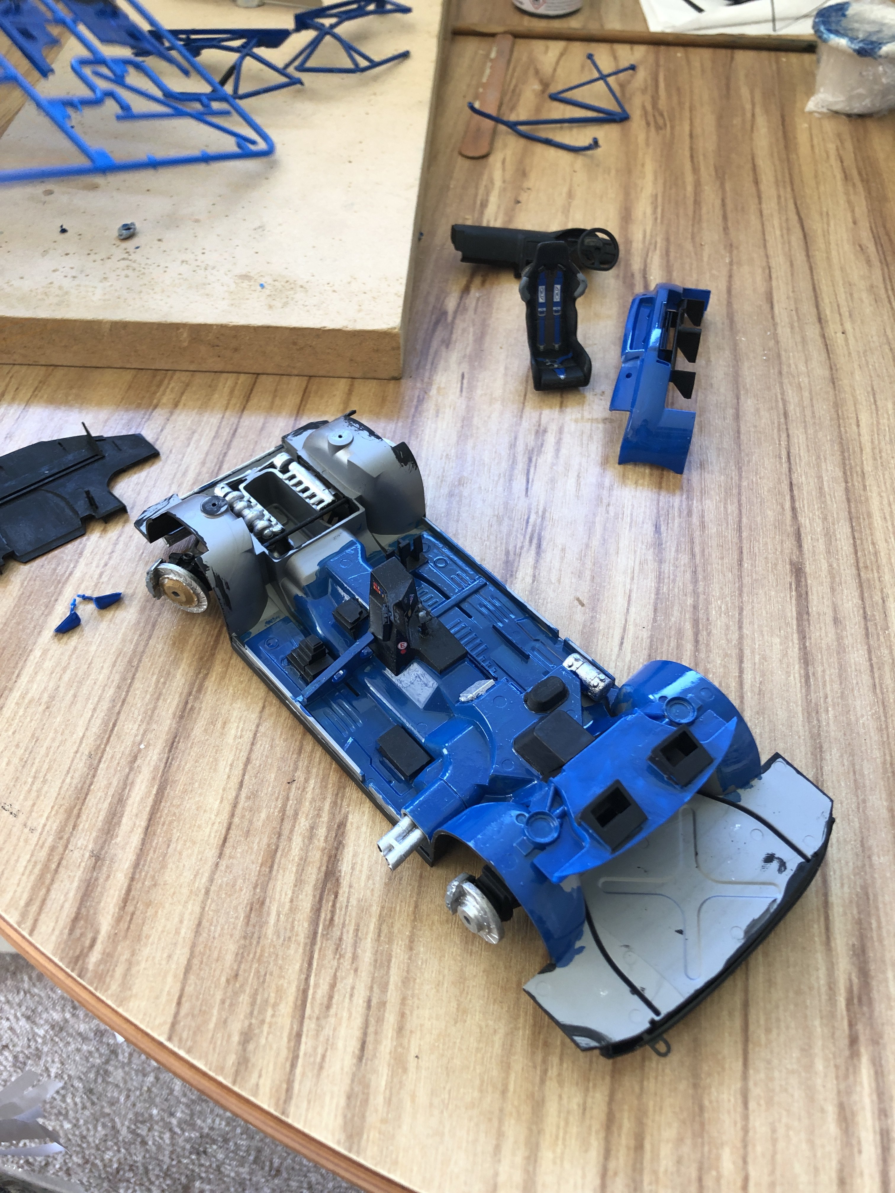
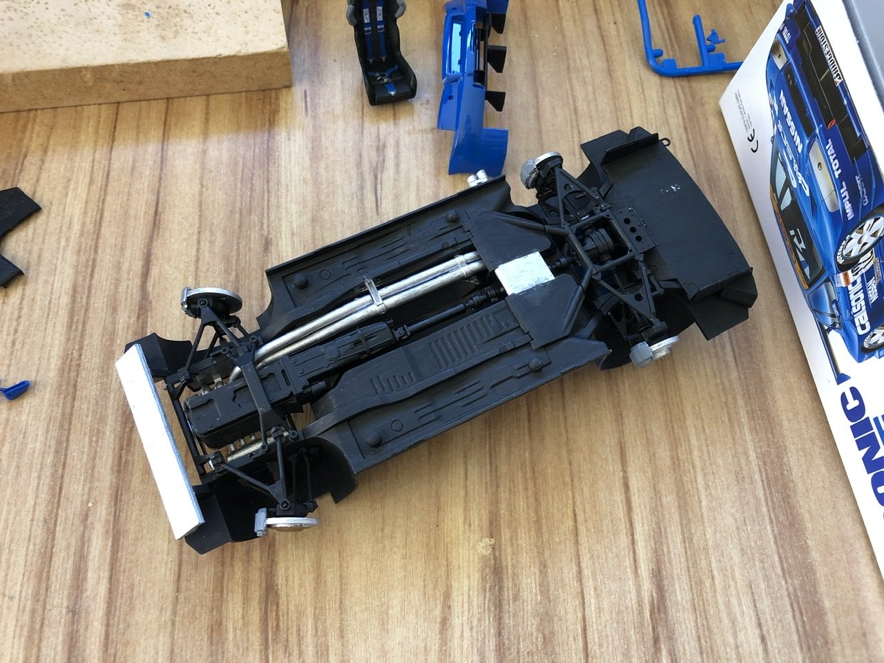
Mr 10 has gotten brave enough to try putting decals on. He only ripped 1 of the early ones but it worked out fine.
1 point
-
Monthly shit-post to stop it dropping off the page. I don't think I'm taking this modelling lark seriously TBH. Nearly assembled. Just got to do a bit of light weathering. I'd rather be mauling the crap out of it but have confined the wear & tear to a bent radiator stay and badly painted black-out highlights on the corners.1 point
-
I haven't got time for this bollocks, especially as the real cars are turning up thick and fast. Nah, I love it really, but how deep's the rabbit hole ? Wear and tear on the rubber track blocks, rust, dust, residual mud. Got a little bit more done this evening, tracks finished so bodywork next.1 point
-
Mr 10 progress so far. His paintings getting neater as he goes and everything’s coming together as it should.
1 point
-
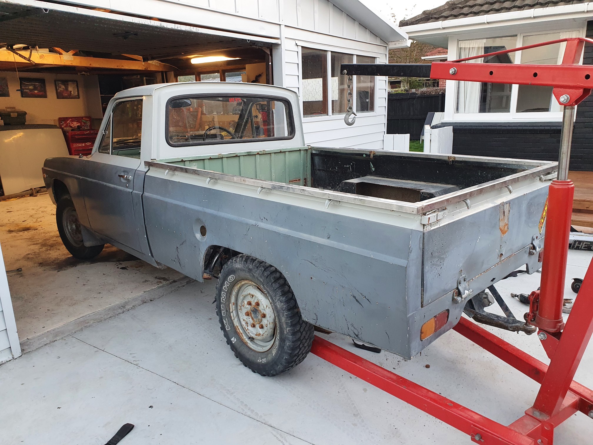
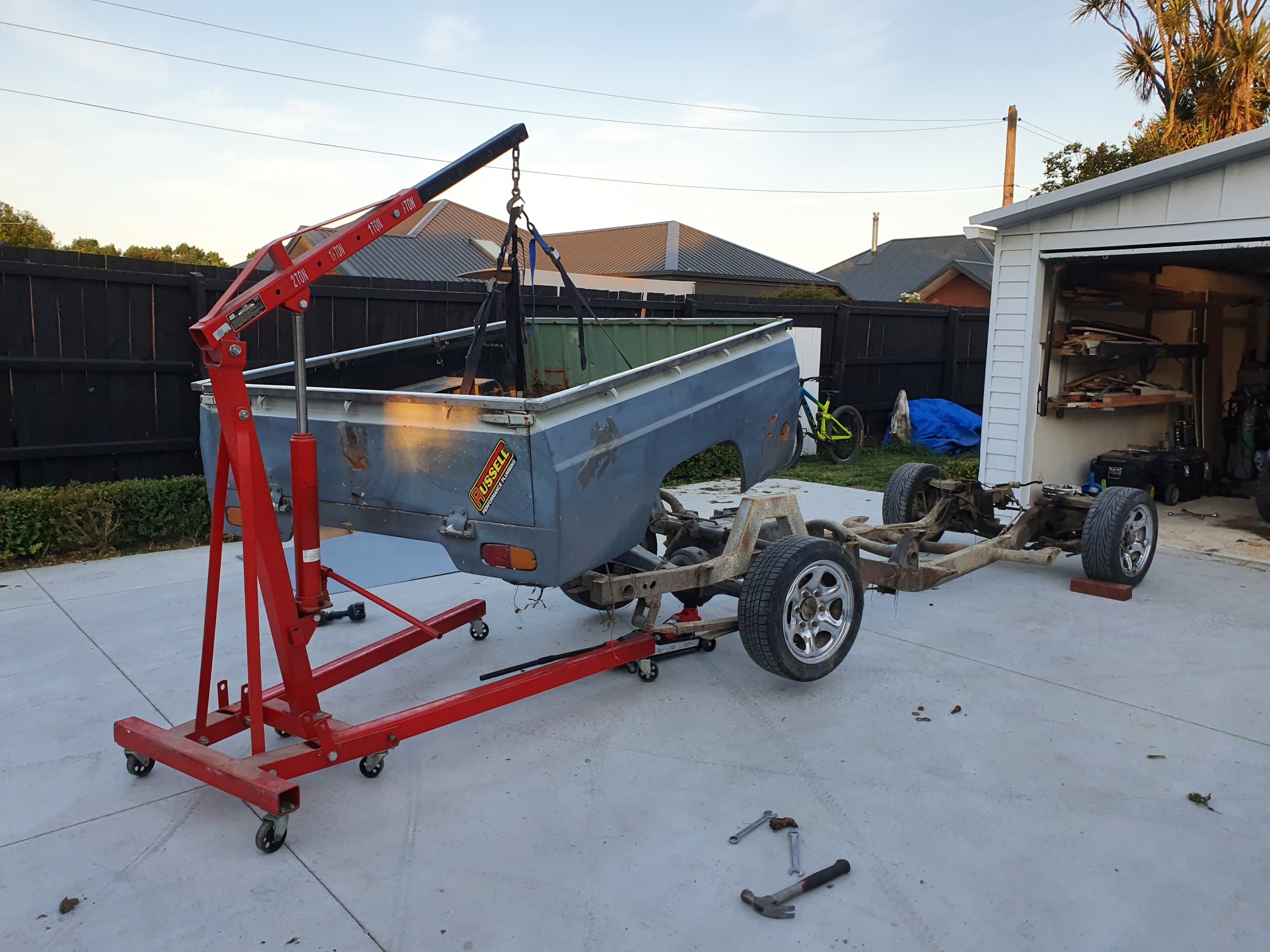
Had a productive day today. Got the chassis swapped over. Damn it was ghetto. 2 small jacks and 4 axle stands haha. C notched chassis is up for sale if anyone wants it. 300 bucks bare
1 point
-
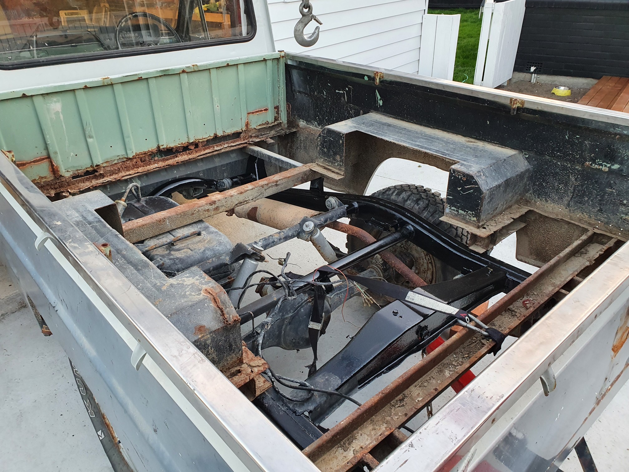
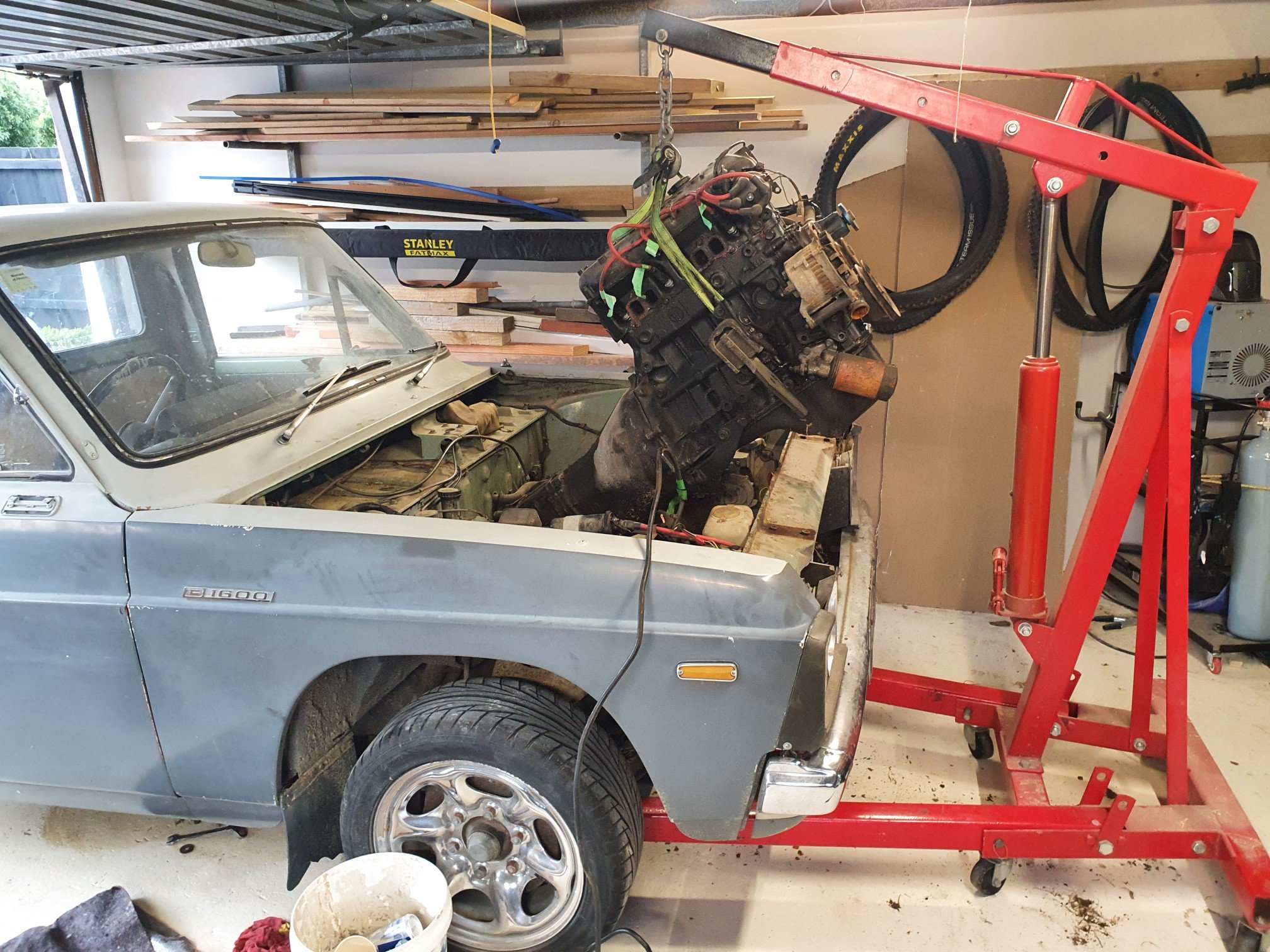
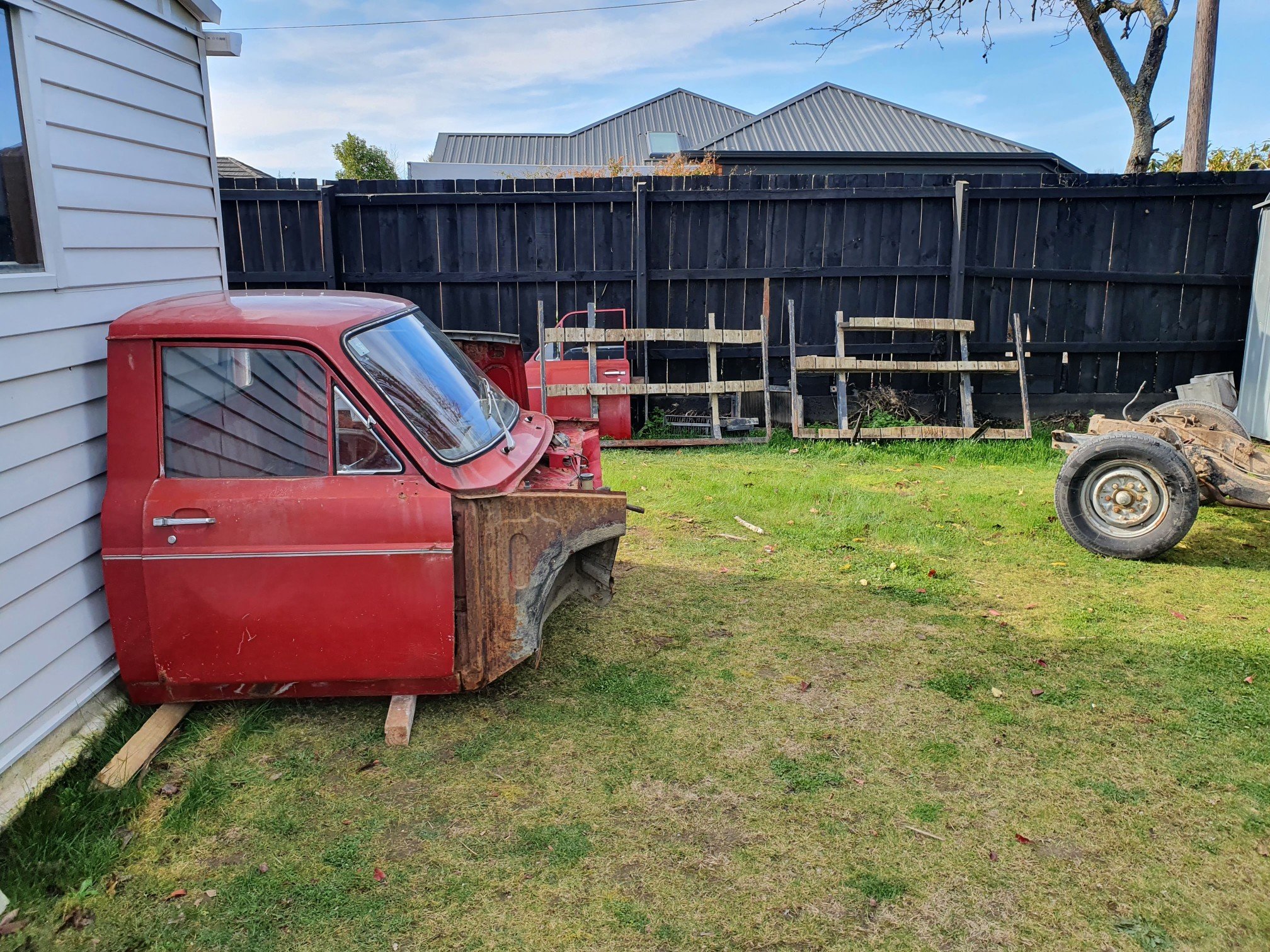
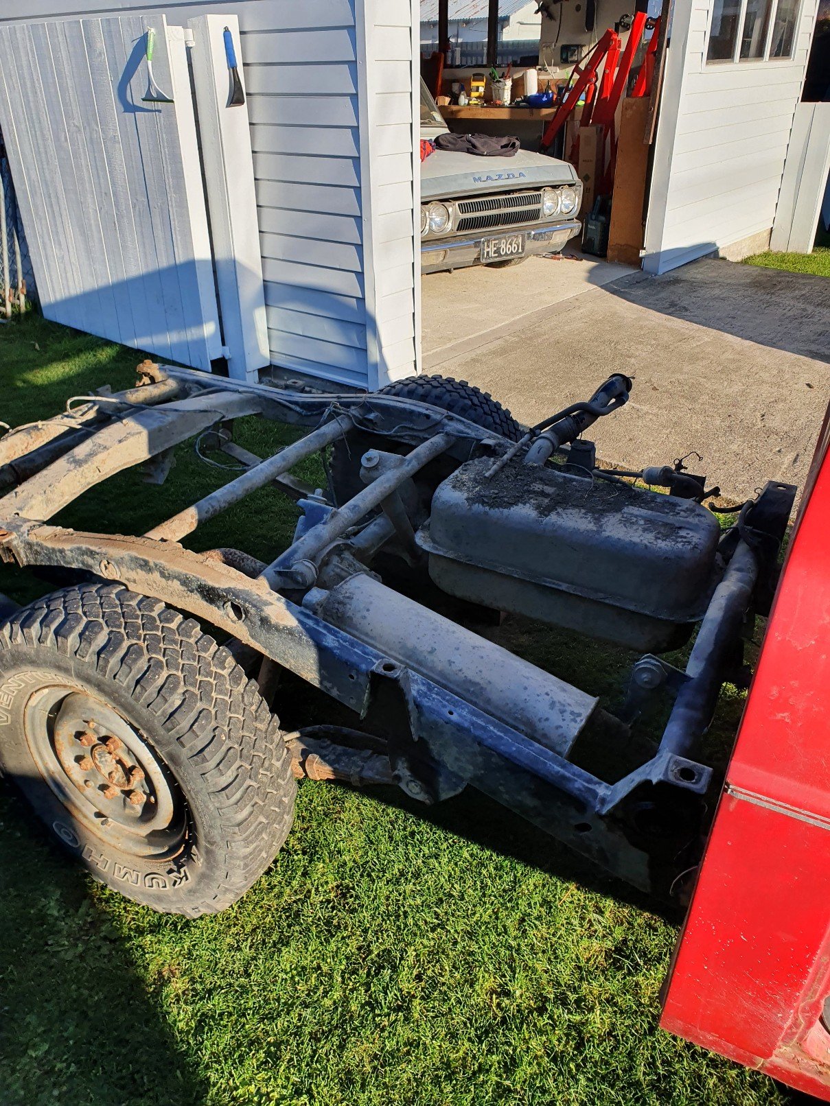
Thread dredge from page 6 haha. Progress has been very slow on this. Lack of room is just a killer. Tonight I pulled the 2l out. One step closer to pulling the cab off the c notch chassis . At least with the motor and box out it will be a little lighter to push in and out of the garage. That's all the progress for now. So here's a boring pic for a boring build
1 point
-
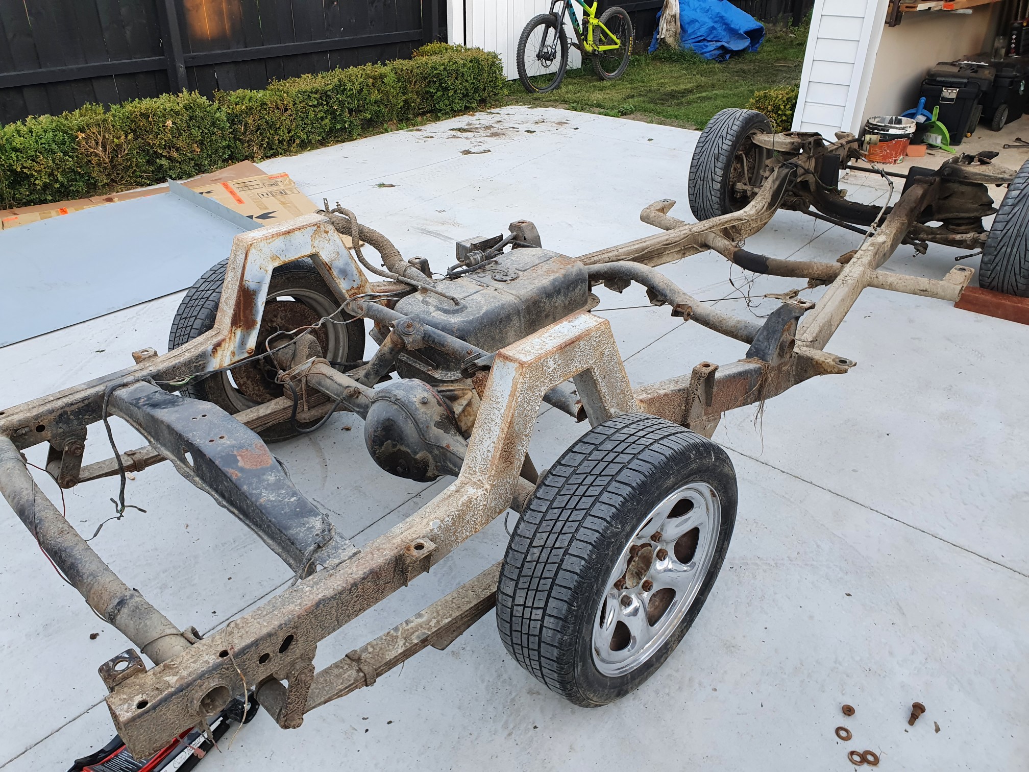
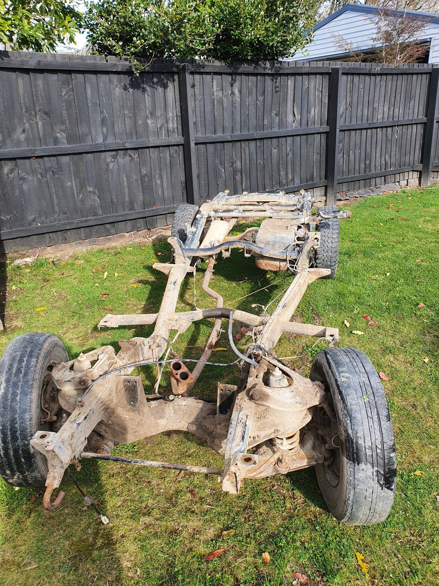
Another boring update. Have now got the chassis I'm going to run stripped of its cab and junk. Haven't decided if I'll rebuild the front end with all the new suspension bits I have before I put my cab on it or not. So it looks like the 2l I have in it is siezed. Have had some deisel sitting in the bores hoping it will free itself but it isn't looking promising so I may throw the 1600 motor in till I have decided what I'm going to do engine wise. I'm about to start another round of renovations so this will probabaly sit on the back burner for a while again. If anyone needa any parts let me know
1 point
-
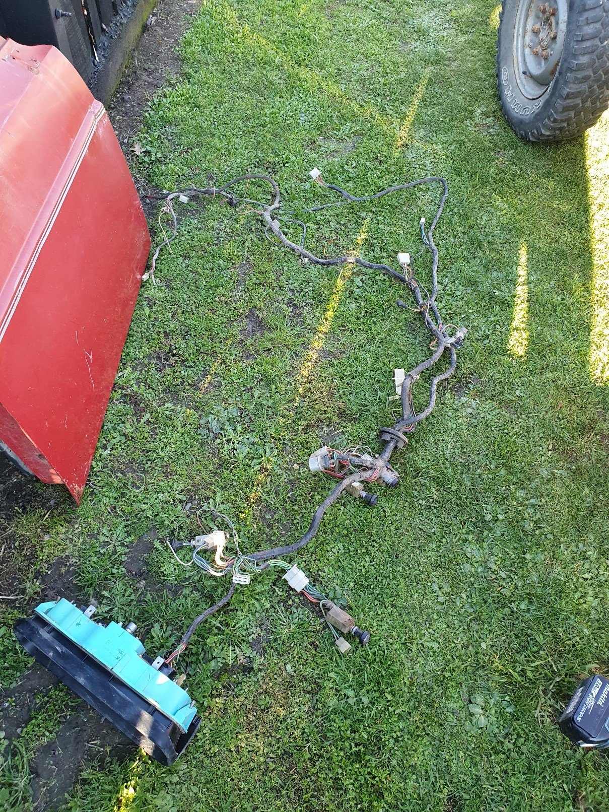
Found some time to actually work on this today. Have been juggling work/life/enjoyment/house renovation time as of late. Not really sure what category working on it comes under, maybe I should have included a frustration category. So this thing has its ignition switch and headlight wiring hacked to bits. Every wiring diagram I have doesn't match my ute so figured I would just steal the loom from the parts ute. With how little the loom contains it shouldn't take long to swap it into the proper ute. The loom from the parts ute looks to have a few gremlins hiding in it too. Possibly due to rats.should be a straight forward fix. I took the motor and gear box out of the parts ute getting ready to clean the chassis up and swap my body onto the normal chassis and do away with the c notch. Have made a bit of progress on the wellside also. A friend has a sheet of zintec? At his shop for me and when I have time I'm gonna head into his work and start to cut out what I need and do some folds in preparation for welding into welside. Here's a couple lame photos but who doesn't like photos
1 point
-
have done nothing for a year. except drive it down the road and back. had to move it to get the cortina in. pumped the tyres up and chucked a battery in it. fired up straight away and idled.1 point


.thumb.jpeg.384ff72c8d2b0ee0d34a7bdedb55bdcf.jpeg)


This leaderboard is set to Auckland/GMT+12:00