
Leaderboard


Popular Content
Showing content with the highest reputation on 02/22/24 in all areas
-
Ha. So pretty much the day after I had cleaned up that old alternator up and got it running on the engine the second hand replacement for my original unit turned up in the post. It came with a 3 month warranty so I'd better check it works before stripping the engine of its ecu etc. Started to fit it and oh.. Poos. It wont fit. So I took it apart, along with the original.. Discovered its just the front housing that's different and I can swap them across.. So while its apart it would be rude not to clean all the parts up and polish it all (tempting fate just a bit...) Fitted to the engine and started it up. Yay - it works and it looks great, which is really quite important given its right there, in the middle on display. I'll keep the other one in storage just in case I need it one day. Now I could strip the engine back down, removing all the cooling, wiring and fuel lines that I had installed just for bench testing. Then I removed the transmission and put the engine back onto the engine stand 2000, stashing it away because its gearbox tinkering time. This Leone transmission has a few little issues that need sorting out in order for it to run in reverse rotation and not potentially turn itself into an expensive insinkerator or coffee grinder. I could probably get away without doing these modifications because the box is overbuilt for the application but I wanted peace of mind. Remember I had acquired the two gearboxes, 1600 and 1800 items, before getting the engine. Ages ago, in fact 4 years ago I think!!! I had wanted to know if it was feasible to run these boxes in reverse. This pic I posted up way back then gives a good idea on what's going on inside... I had already worked out some of the issues back then and knew what I was up for. With more study I found a couple of other areas that need addressing. Here's another bit of wonderful scribbling I did this evening.. The pink arrows show the new axial forces that are being imparted onto the main (driver) shaft and pinion (driven) shaft. The circles are areas that I think needed attention to make sure it doesn't throw it toys from the cot. 1 : the blue circle. Under high torque loads this area could possibly create the sound of nashing teeth but with much messier consequences. The top left one being the third gear driver wants to move to the right and clip the teeth on the bottom right second gear. In normal rotation they would move apart. There's 1mm of clearance there which is probably enough tbh. But I wanted a bit more and had already worked out how I could get it with no other issues and just a bit of tool making. Which is fun. 2 : The yellow circle. This ring was no going to take thrust loading. It is a strong ring and has a deep groove but I wanted to make sure there was no way it could ever shift. 3 : the green circle. In this area there is a thrust bearing that also acts as a neat little oil pump and squeezes oil through the gear hubs/bushes. Under the new loading the thrust aspect is removed but I still wanted to it pump oil and it was going to be the wrong shape to do so in reverse rotation. So I set to work and checked off each job. I made a bolt holder for ease of reassembly - several different sizes and lengths. Once apart I started with the gear side clearance. First off I needed to split the mainshaft assembly down. 4 years ago I had out of interest tried using a puller on the spare 1600 box, which shares the same layout and design but with smaller parts in many cases. The puller didn't work. But this time round I have the rather handy workshop press I made. I just needed some extra tooling to do this job. Starting with some press plates... Allowing me to carefully press the shaft out... Because I'm not posh (or rich) enough to own a surface grinder I needed to make one. Yes its a bit basic but it will work. I made this... Which allowed me to do this.... I ended up with this gear having the 0.5mm more clearance I wanted. Super happy with the result. Now onto number 3 - the little oil pumpy thingee. I went to my friendly engineering workshop in town and got a big lump of 4140 steel. I drilled it out... Machined out a ring which had to be an exact width. Just in case it needed finishing after the hardening process I made an abor to take it.. I carefully machined it to the right profile, cut the sides down and filed the shapes in, just like the original but in reverse. Happy it was going to work I heat treated it. I have not done any heat treating for over 25 years since I spent a fair bit of time in the blacksmith department while doing my apprenticeship. But it wasn't a super loaded critical component and just had to have a durable hard surface. I didn't take any photos. Hannah was there helping as I carefully heated it up with the oxycet to the austenitic stage and agitated it in some lovely rice bran oil (because I can be posh sometimes) then slapped it in the oven to temper it... Following morning I polished it. It came up sweet and the old file test showed it to be as hard as the oem item. You can see the reversed design here... Here's a little vid I took showing it in action... While stripping the mainshaft down I was also pleasantly surprised to discover that this 1800 box has needle bearings in all of the gear hubs unlike the 1600 box which uses bushes on the mainshaft. So oil starvation would not have been as much of an issue but I'm still really happy I did this modification. Last issue to sort was number two - that ring on the bearing. It would hold fine I'm sure but if could make it bulletproof then why not - it's just a bit of extra machining. I started with another lump of high tensile steel and machined out a ring to suit... This fits over the other ring and then the main thrust plate that sits over the bearing was machined out to suit my reinforcement ring. Its all held in place by the end housing which I have yet to fit. All the potential issues covered I set to cleaning out the casing and then started reassembly. In doing so I discovered that the original axle seals are sided on these boxes. They have those helical lines on the lip surfaces which aid in pulling/pumping oil back into the oil side of the lip ( the lip does not actually touch the steel when the axle is moving and in fact runs on a tiny bed of oil) which I had not realised before I'd bought plain lip seals from an engineering supplies. This pumping capacity is shown to be twice as high in helixed seals. Subaru fit left and right handed items. But I'm running mine in reverse. Luckily the originals were in excellent condition anyway so I machined up a stepped tool, popped them out and swapped them to the other side. The diff axle seal surfaces came up good after a clean. Cute little diff.. I'm now about ready to put some 3 bond gloop on the case half and drop the other side in place. Its looking all very nice, clean and shiny in there...41 points
-
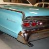
Also shit I forgot to mention that I put the rear bumper back on. This was harder then it sounds but basically I pulled all the brackets apart, soaked them in evoporust for a few days then painted them all. I beat most of the dents out of the side bits and then bolted it all back in. One of the mud flaps was broken in two so I welded it beck together with a soldering iron using cable ties for welding rod. Is it good as new? No. Will it last a thousand years? Also no But it's back on the truck and works until it doesn't so I'm calling it a win.
 10 points
 -
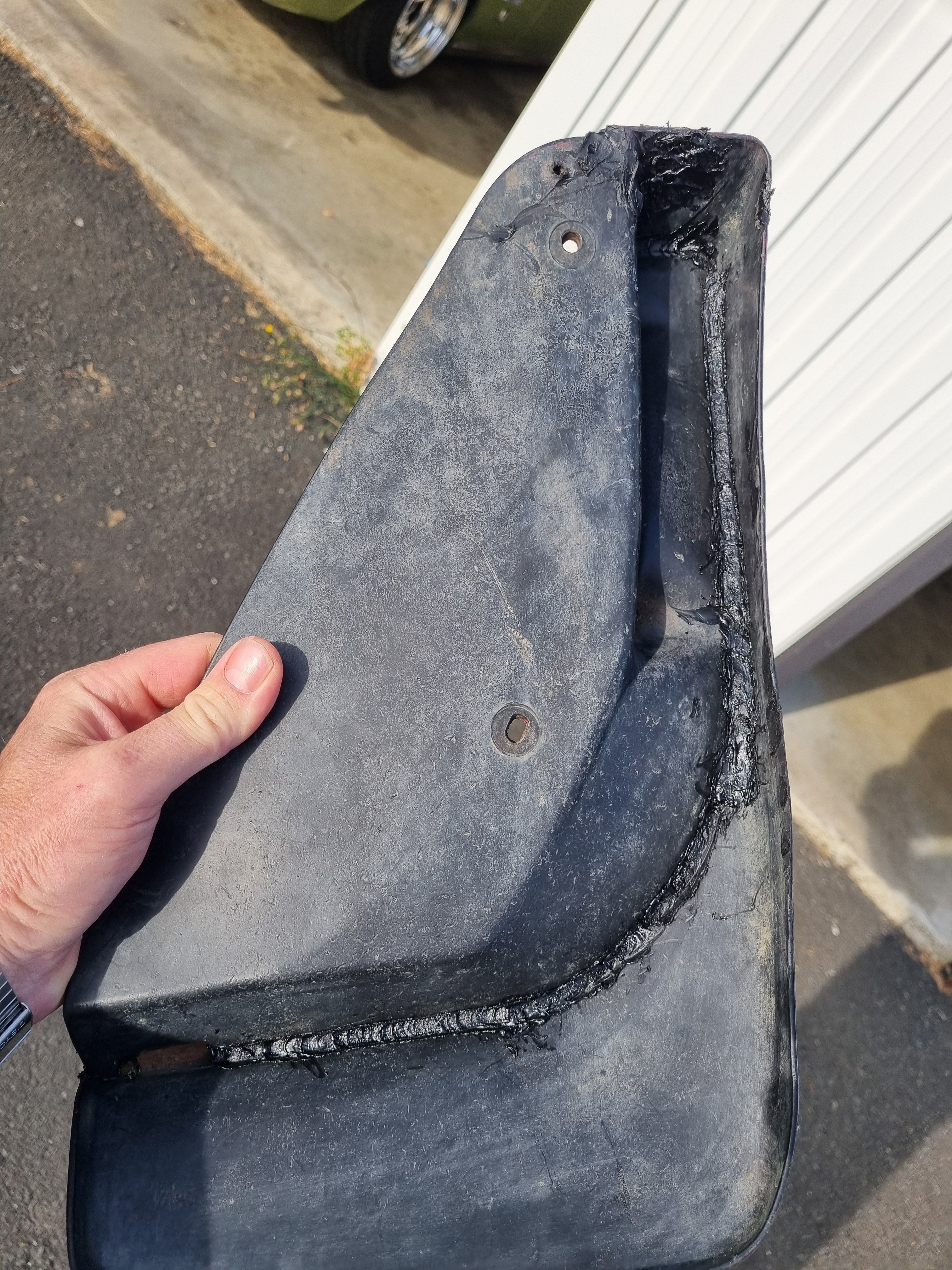
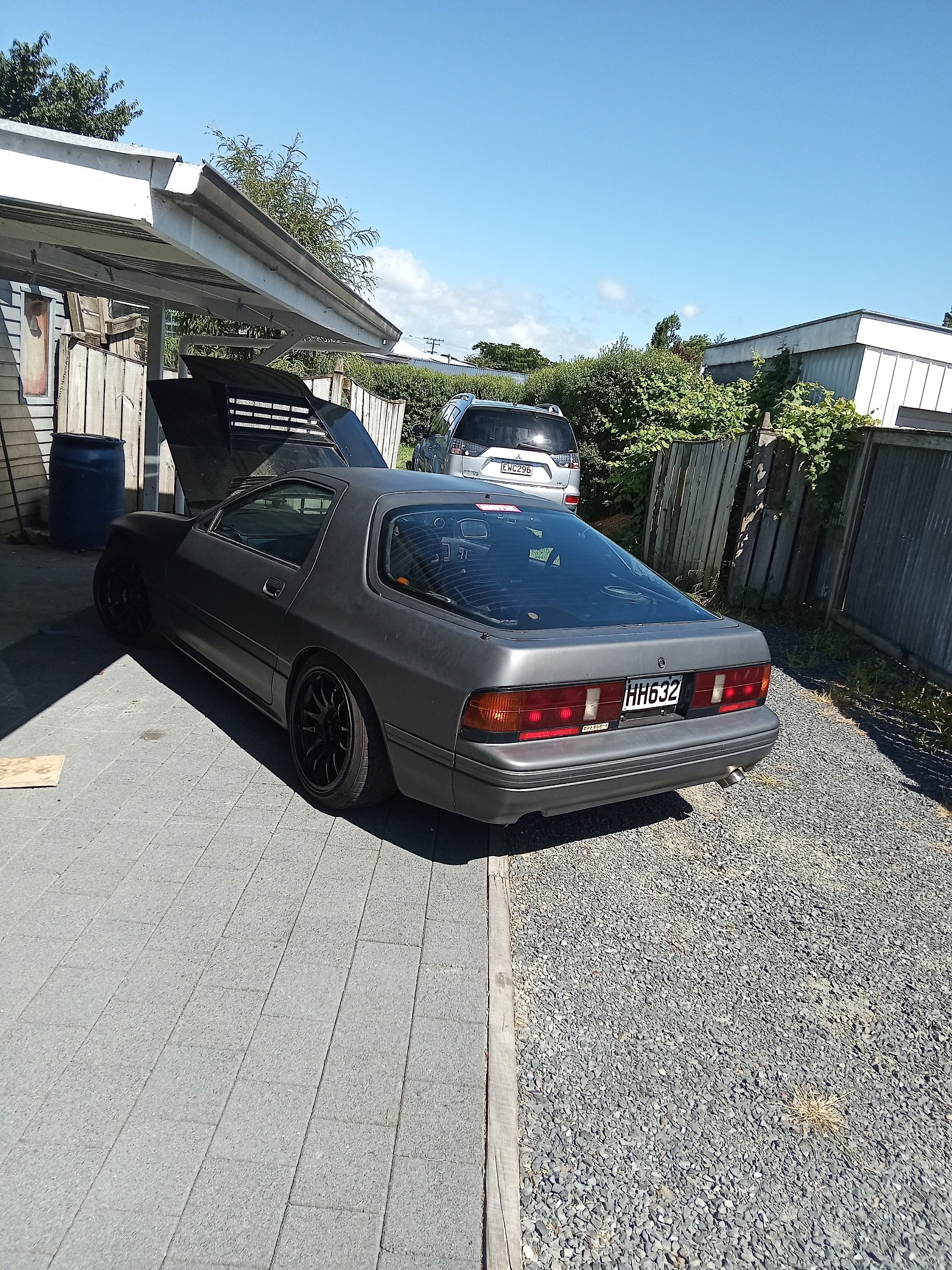
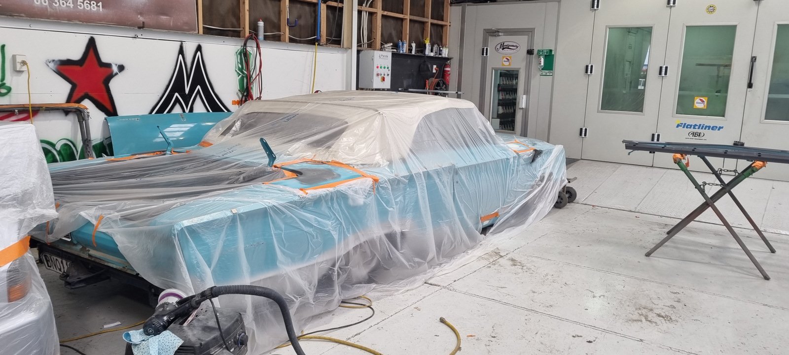
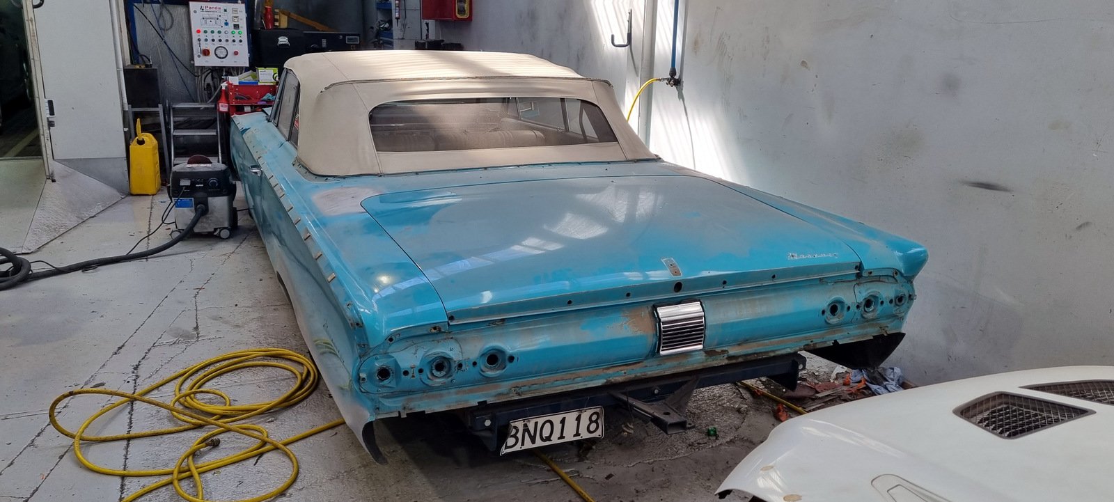
Body painted, trunk and hood should have been done today. Popped up the road and collected the rear bumper and other parts from the panel shop. Plan is to be all back together for the Beach Hop.
9 points
-
Back in the country means back in to work on the ol' 86. Firstly, the time has come to get the front bumper repaired. So, off it came and off it went. The plan is just to make it structurally sound again, I think there are too many hairline cracks to warrant a full resto on it. If it's structurally sound and painted, i'm a happy man. The bro's cracked in to it! When i've previously removed the dash, i found it not possible to take out the dash clock surround without breaking it into 30 pieces. This has been an eye sore for years and luckily toyota still make them new Next was to install the JSP coolant overflow/oil catch can combo unit. 10x better than the previous solution. I will hook it back up to breathing back to the engine, I just need to acquire a -10 120 Degree fitting so that it can point down to the ground a bit more as using a 90 degree will make it hit the bonnet Turbo water lines installed. I need to order another -6 90 degree bend fitting as I didn't order enough, luckily I had a -4 premade hose sitting about which works fine, but it's 90 Degree to straight end hence the U bend to where it connects to the back of the head. This will be resolved shortly! Tidied up the NASA heat shield for the overflow bottle, I will get a beanie at some point for the turbo but hopefully this is sufficient for the interim. I've also misplaced some U Channel moulding I was going to install around the folded edge of it so that it wouldn't be possible to cut into the rubber line to the windscreen jets. it'll turn up.. Clean! Gave the interior a clean, still need to address the small rip on the drivers side seat.. I've always wondered where the handbrake light loom was situated in the car, I assumed that it was just that I was missing the wires and it never had them. Turned out in my spares box I had the spare loom, plugged it in and we now have a light. something that isn't that helpful just good small win For 10 years i've put up with using a wooden stick to hold the hatch up. FLOS.ie have new gas struts so in they went. much satisfaction TODO: - Replace oil pump. I'm having lower oil pressure at higher RPM's than I'd like (with a rebuilt bottom end), so i've got a spare oil pump which has the SQEngineering pressure up spring unit to hopefully address that. If that doesn't resolve the issue i'll be getting plasti gage out to measure the cam cap tolerances as I can't think where else I would be losing pressure the way that it is. - Recheck pinion angle since the 15" rims and slight height differences to bring back to 1.5 degrees both sides - Pull out gearbox to replace the output shaft speedometer worm drive. The plastic gear for on the speedo output is stripped, and without knowing what the worm drive it suits, better to pull it apart and replace it with the correct stuff which I now have. - Maybe try cert?7 points
-
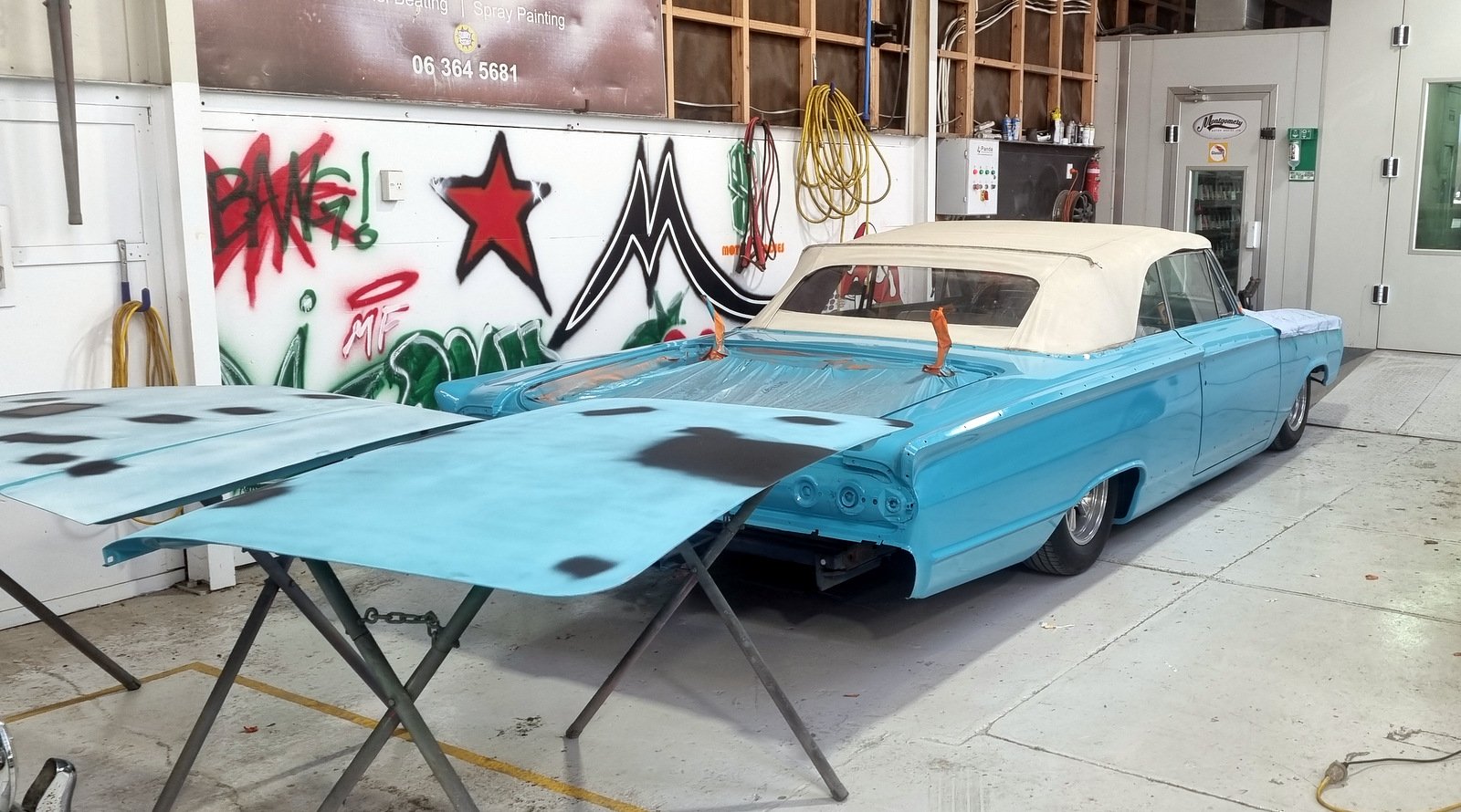
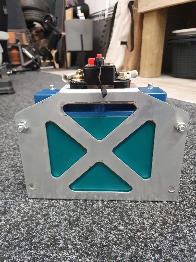
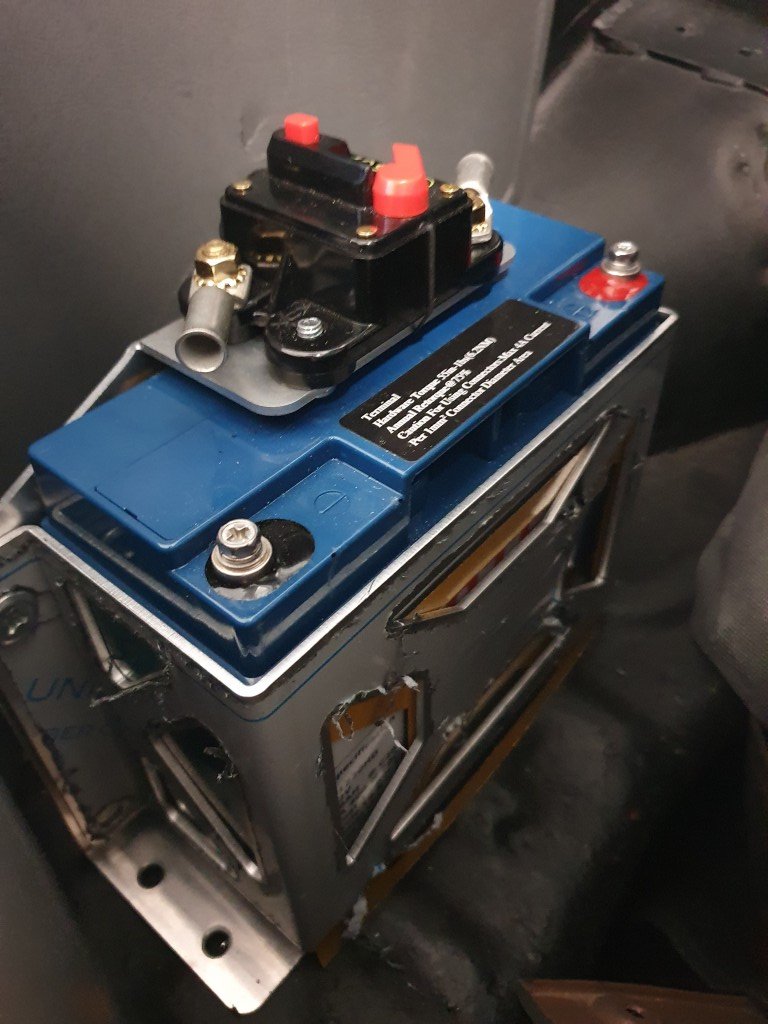
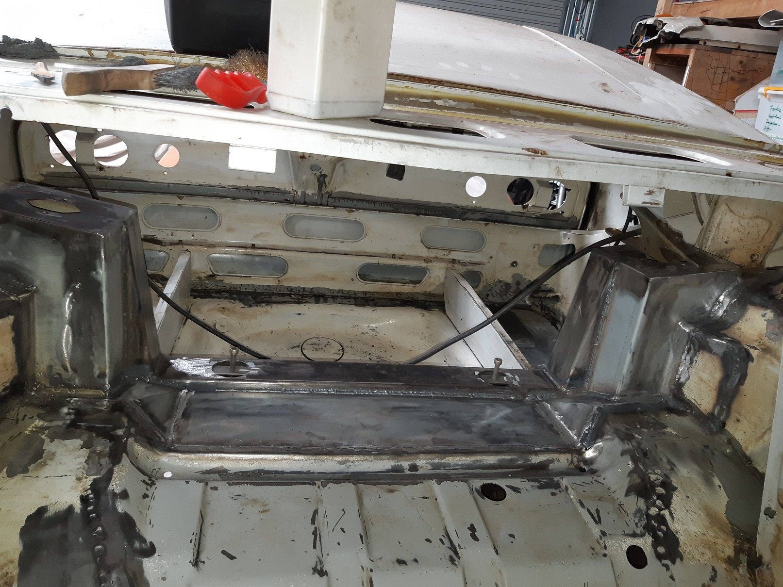
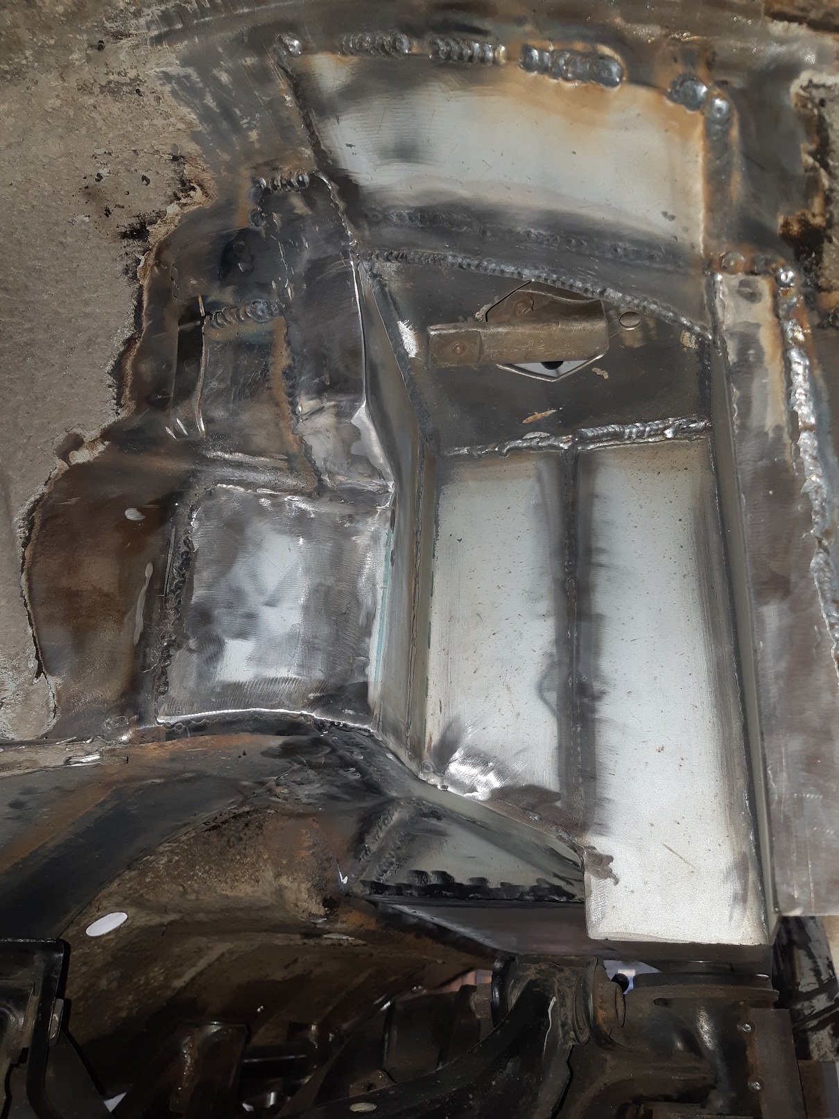
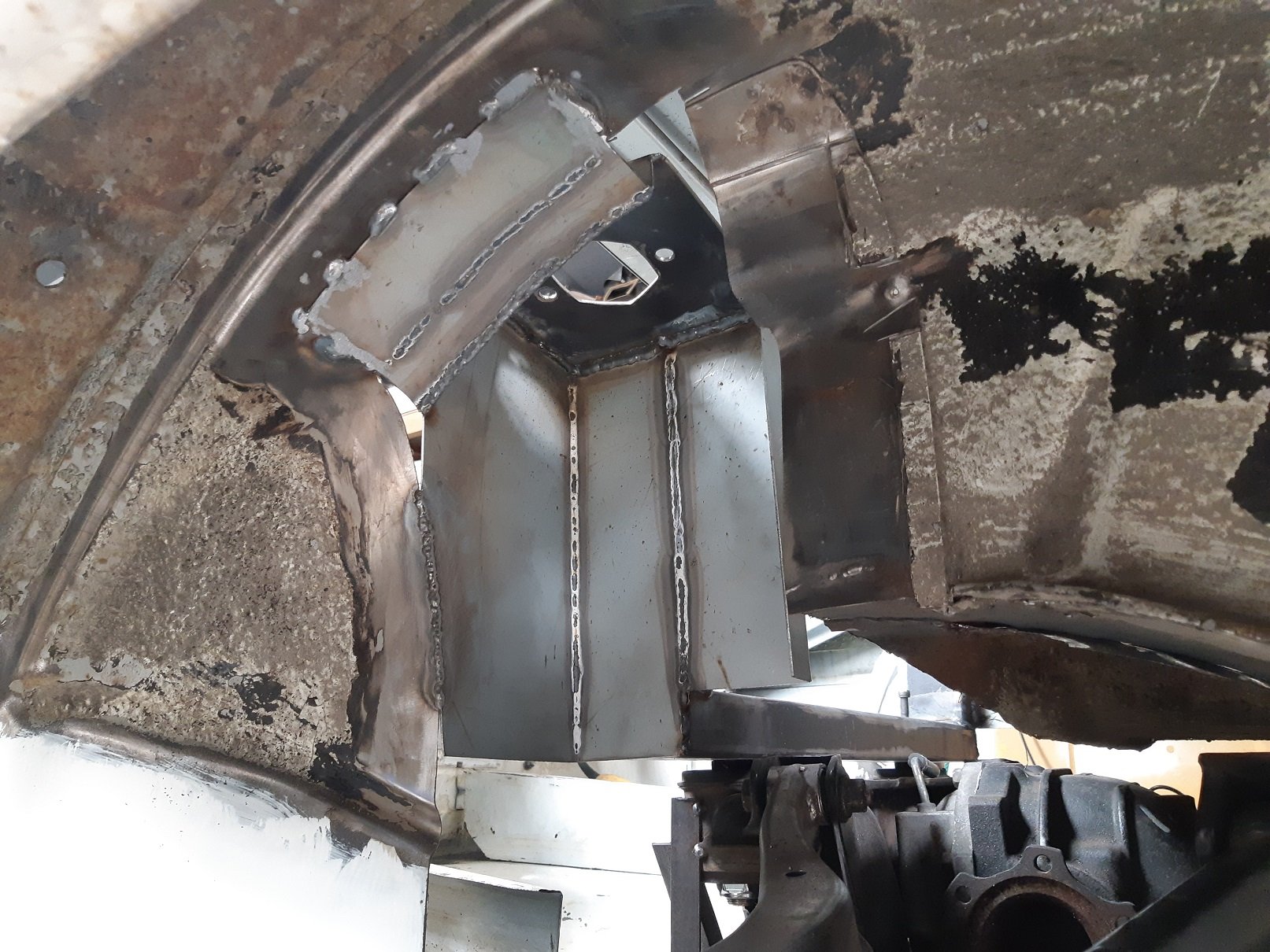
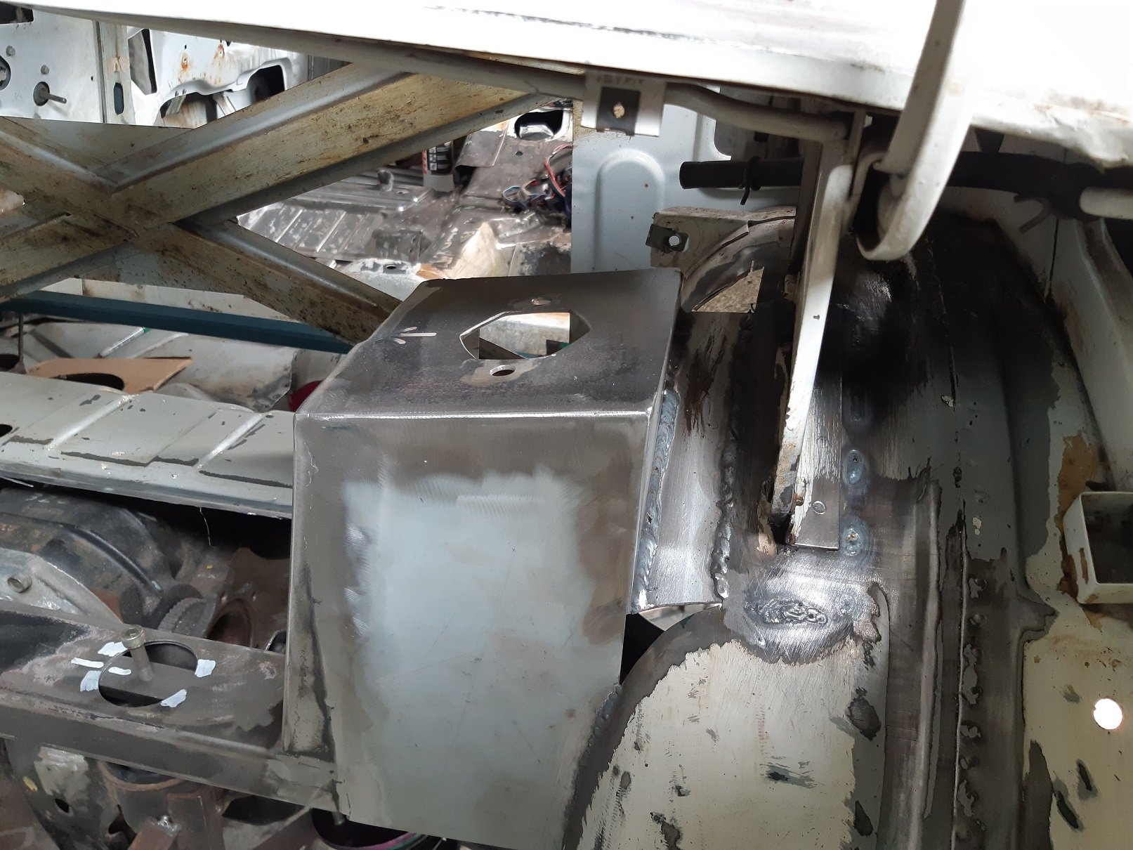
Battery box with breaker mount. Need better fixings for the battery mount but works for now. I managed to get the breaker JUST to fit on the top bracket, probably a couple of threads welded on would be best to hold it down. Currently the dome head fastener has a slight protrusion into the battery zone which I don't like. The bracket I got with the battery has been repurposed to mount the ECU. This one was a lucky find for cheap off marketplace. PC680 sized mounts WILL fit a Vertex battery easily. Note, there is a thick rubber gasket layer between the battery and battery bracket.
6 points
-
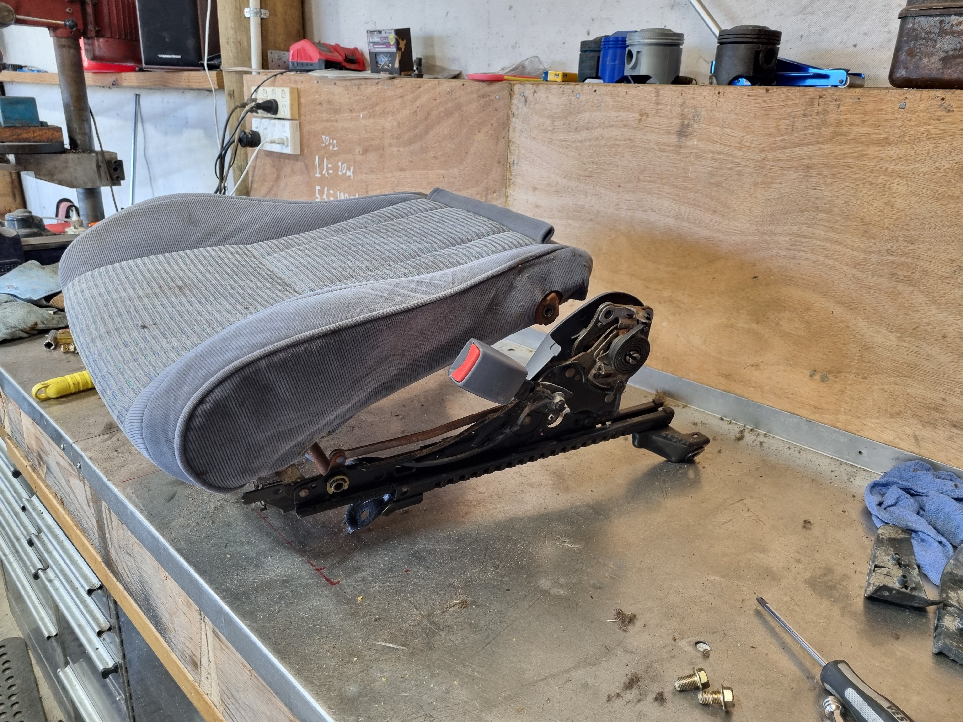
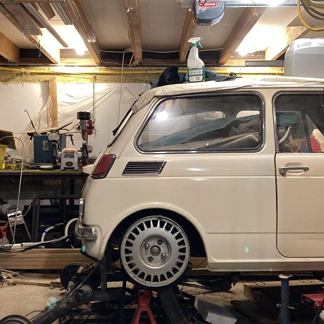
With no idea what I'm doing I decided to pull the seats apart and see if any parts are interchangeable. Long story short, the cushions can be swapped over. So I did. I now have a fucking ace drivers seat and a fucked passenger seat. Then I found a pair of good looking seats on TM in the same colour so I bought them. Between the 4 seats I should have no issue making 2 good ones. Stoked tbh
6 points
-
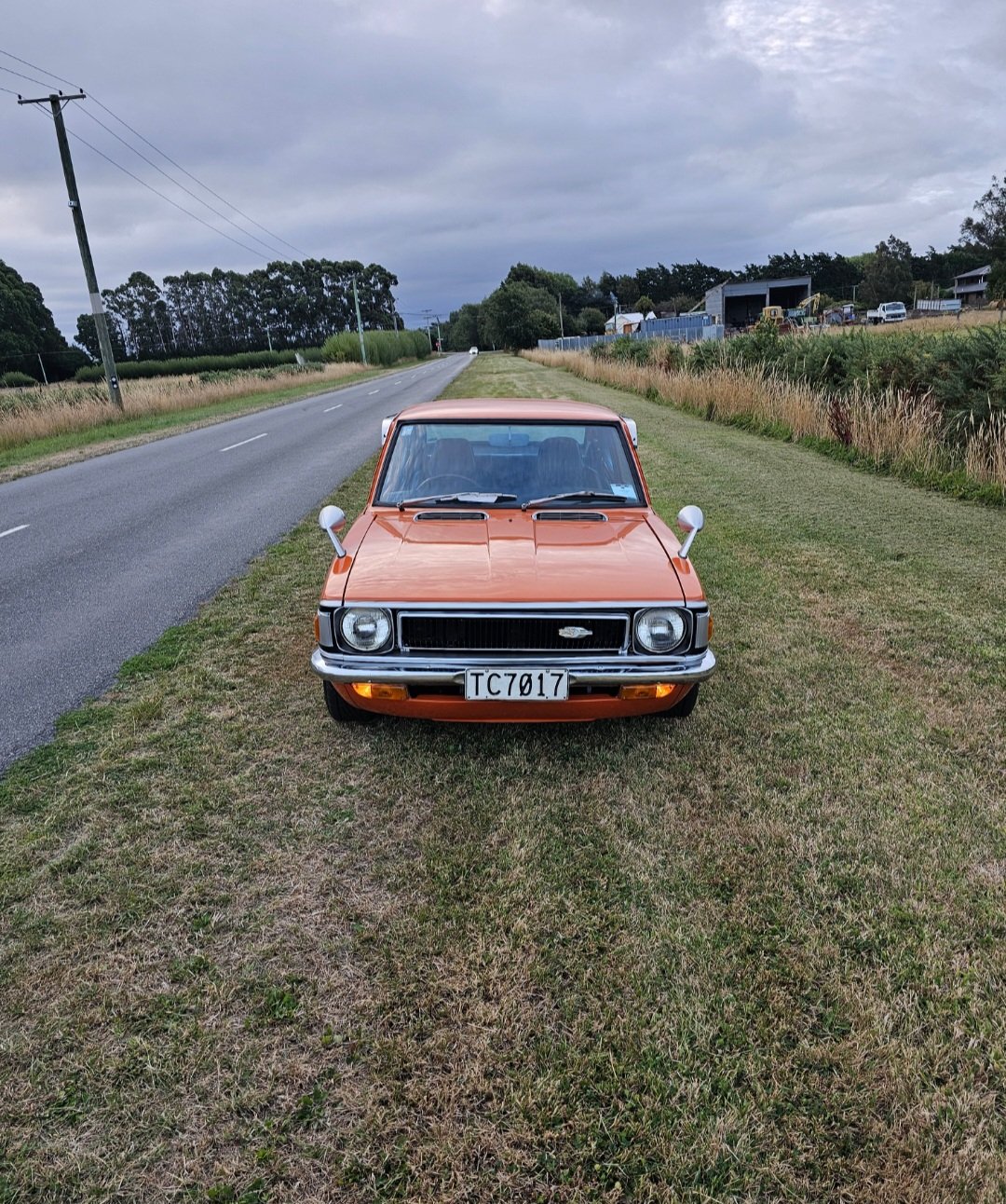
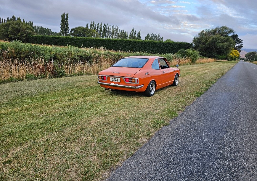
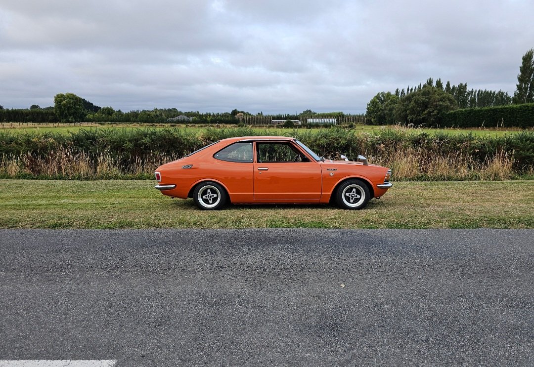
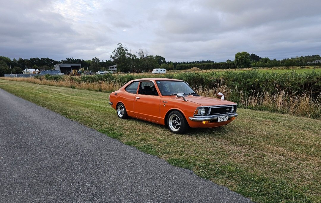
As far as I can tell it is, its an early 3 bearing motor. Carjam suggests near on 200,000kms and 32 owners - so.. yeah.4 points
-
Good advice I reckon.3 points
-
I’m not sure if it shows up in pics but I had a bit of drama with the trade me special sanding discs I have. they literally clog up, then drag the hard bits of paint and redistribute it over the sanded surface. Good thing I had found some Norton 320s I purchased from SCA but forgot about. they’re decent, as soon as I ditch the 125mm sander for a 150mm I’ll move to quality abrasives Once that was done I filled any pinholes with fine filler. Mind my mess, I’ve lost my thin knife applicator Buzz it down Then wet sanded it with 400+block and paid attention to the edges. After that scuffed the primed panel edges with a red scotch pad and scuff paste, and the blending bits with a grey fine pad the fine pad is used as it’s finer (duh) and creates less scratches for the panels that are receiving clear coat only. If I were to use the coarser pads they would make scratches that would show in the clear. got this outer bit of the sill too as this shows Unfortunately cut through in some areas, my applied paint was so thin, but the paint beneath it was thin too. Makes sense as I got advice from the wrong guy who has like 30 more years experience than me, and the original paint was so faded it was starting to rust in places. Where it’s super small and in a place to be cleared, I’ll touch it up with a small brush. Other places will be re-done. Noticed this mistake on the drivers door I had polished. Previously mentioned guy told me he could paint a car with a litre of paint. I shouldn’t have believed him as I knew better. So now I’ll have to paint the whole rear door, paint the lower bit of this one and edge on b pillar side and blend it out. Hosed and wiped all the dust off, making sure to get in the wheel arches and get out 29 years worth of road crap did a bit of daydreaming, about intercoolers, more low, lips and body kits2 points
-
Jacked it up to save my old back Guide coated, no pic but imagine orange dust all over, 240 wet, rinse off, then dry, guide coat again and 320 DA.2 points
-
Needs a better muffler, anyone know a brand that will shut this thing up for sure ? Adrenalin r, boiler, other? 3.5 inch too big to ask of a muffler to be quiet for a wof? I want to be able to run this on the street but not have a massive amount of exhaust backpressure, Link to discussion above...
2 points
-
https://www.trademe.co.nz/a/motors/car-parts-accessories/austin-rover/listing/45654395092 points
-
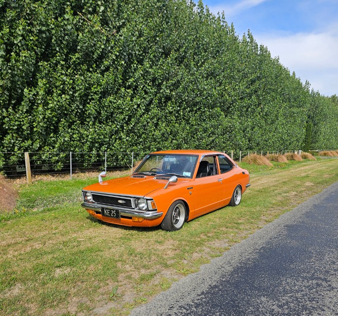
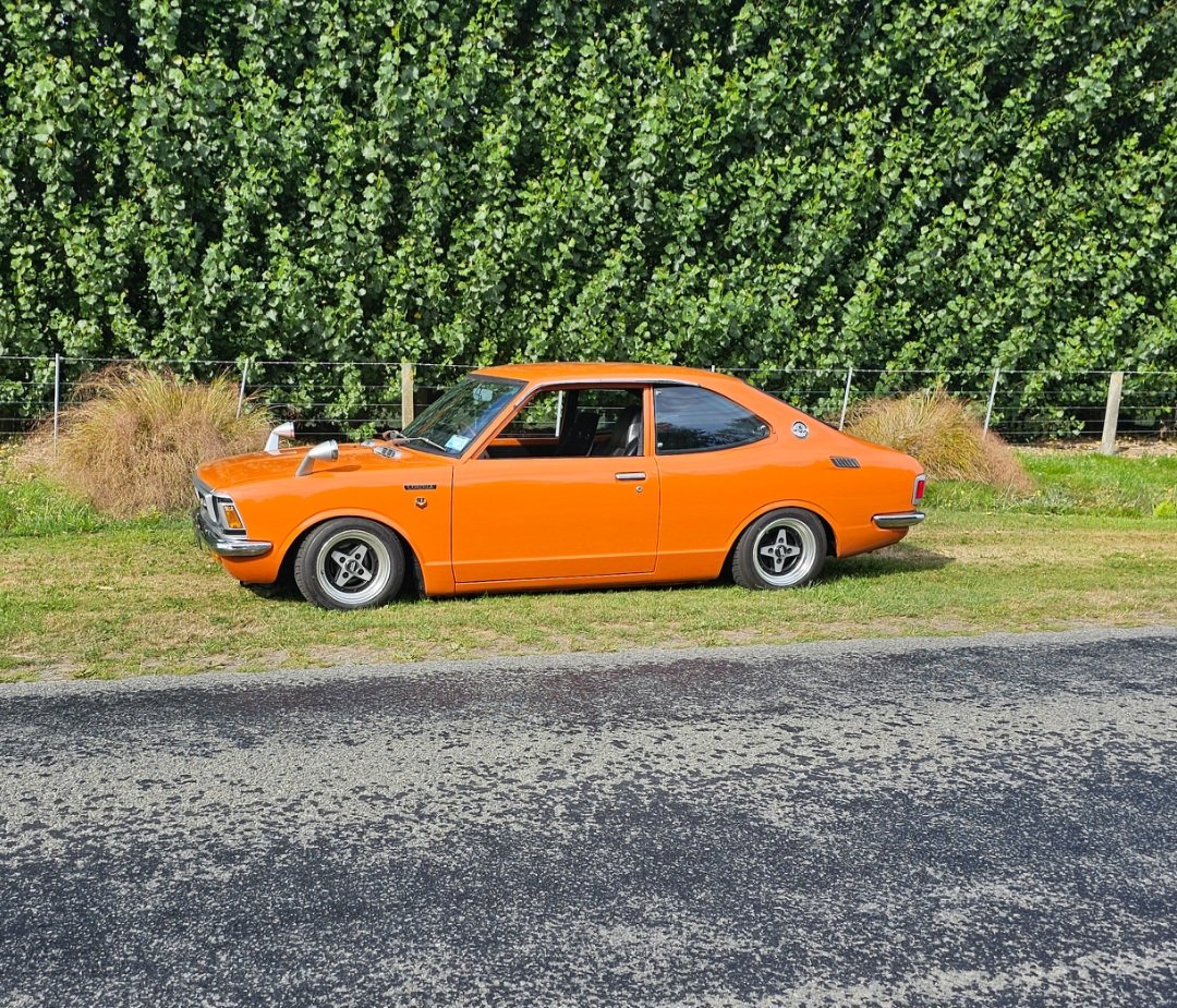
Now to enjoy it
2 points
-
so i done some digging and some searching around with the rims. wasn't having any luck with finding one so the next step was to look at different swing arms to either modify or try fit in the rear of the bike. a Suzuki gs1200ss swing arm popped up for sale in tga. i have a mate local to me that has one, so i shot around to his house with my stock swing arm and got some rough measurements to see if it would work to modify and the common consensus was that its probably going to be the best option to make a swing arm work. so i hit the buy now and had @Mop Head pick it up for me. had a few people concerned that it wasn't going to work and that it was going to be a rather large thing to undertake but i didn't really have many other options if i wanted to fit this 5.5 rear wheel in. and after some comparisons and some measurements the 1200ss swing arm is rather larger and stronger. factory swing arm is 60.2mm tall and 3.2mm thick the suzuki gs1200ss swing arm is 74.9mm and it is 5.2mm thick time to chop it up. gotta trim it down a little bit on the width as well and removed the twin shock mounts off time to get more precise with the measurements chucked them in the mill and @Kimjon showed me how to do some things then we needed to cut some space for the rear shock like the stock swing arm. got it looking like this and i took them home to get them welded up and to do some more measurements cleaned my work bench and got busy again. worked out where the center of the swing arm is and done some basic math and made some brackets. factory mounts trace some out and draw them a bit of grinding and a stepped drill bit later and thats one side all sorted. the bottom side now, kim had already cut these out while i was doing other stuff at his house one day. i trimmed them to shape and chucked them in the bender (vice) and got to shaping them up and making them fit kind of a before and an after well during that time i did go to @flyingbricks house and steel this lathe to re make those peaces that go in the top of the mounts. we some how made the center hole to big. i reached out to josh to see if he could weld these up for me but some times he replies way to slow and often has stuff going on in his own life. so i also reached out to @Rhyscar to see if he wouldn't mind doing some welding for me. he said to pop over and we could run through it see if it was possible. next images can tell if you if it was or wasn't so happy with it. back out at kims again while i adulted with my daughter at my toes. time to try make this fit in. hey thats close enough, lets put the seats and plastics on before i go to see how it looks blue tooth chain but we still got a fair few things to do. daughter loves granddad garys motorcycle so she wanted to sit on her seat. and we are now up to speed a bit more. huge thanks to those who have helped out so much so far and kim for letting me keep it in his shed and use all his tools2 points
-
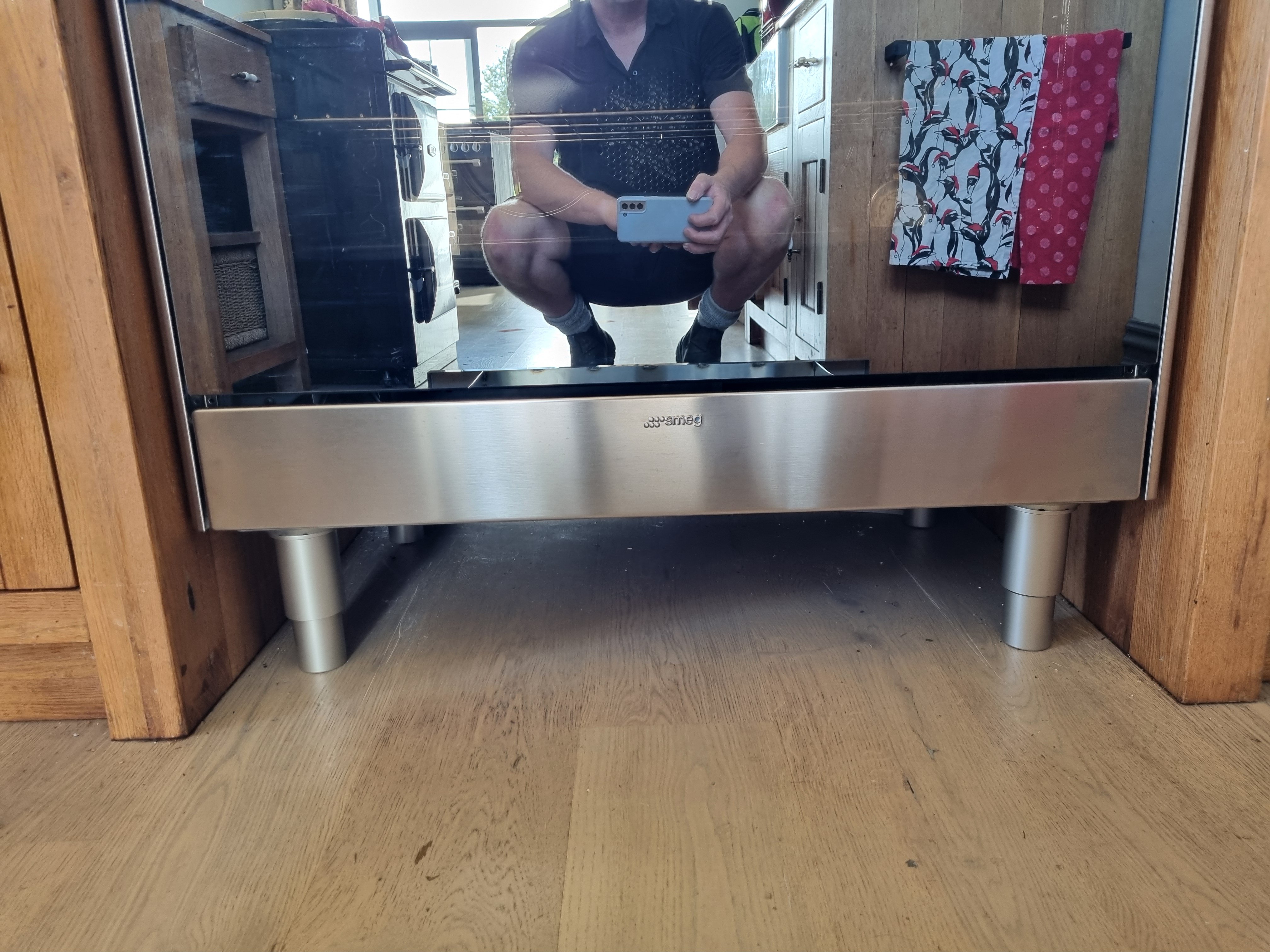
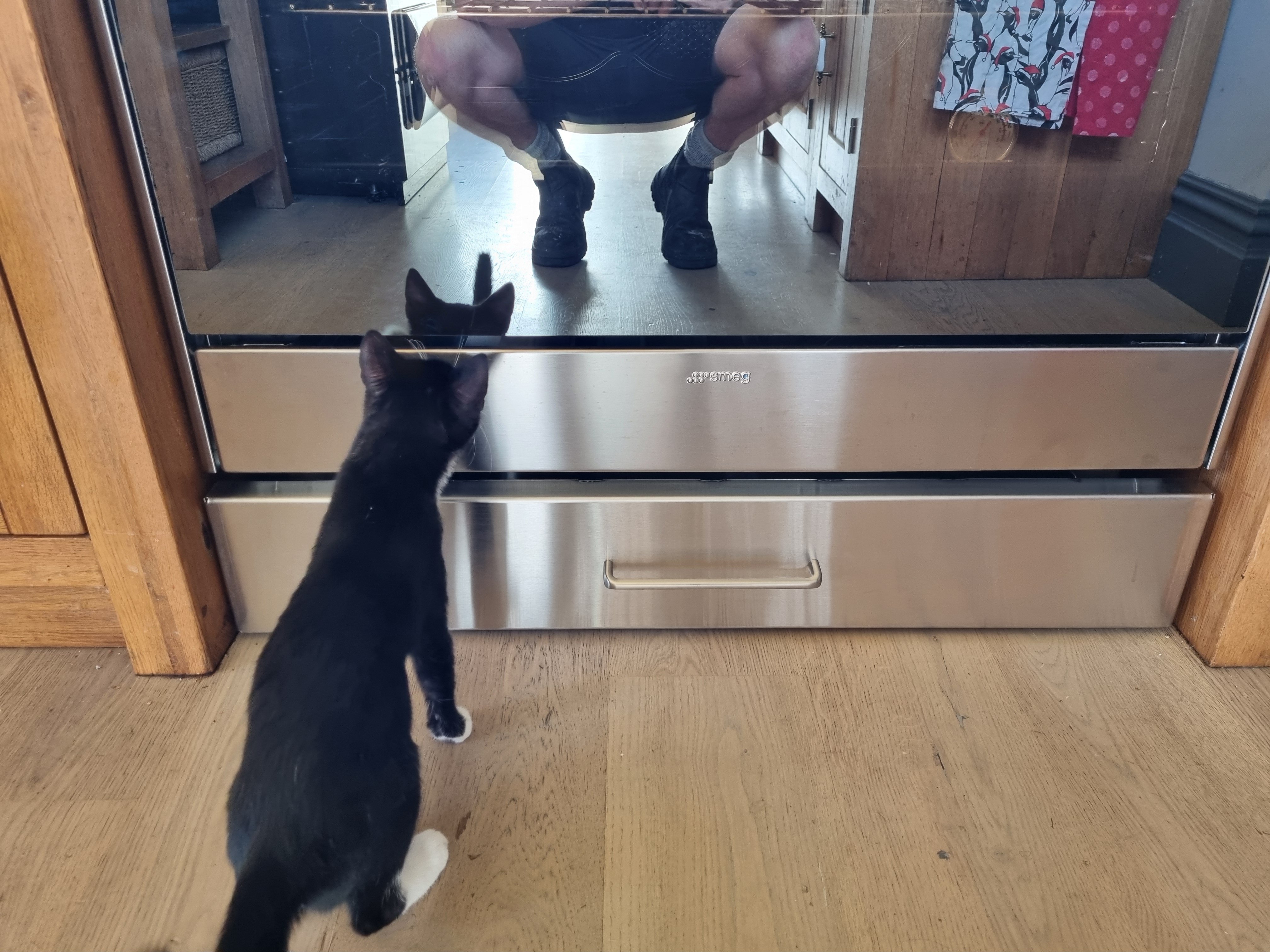
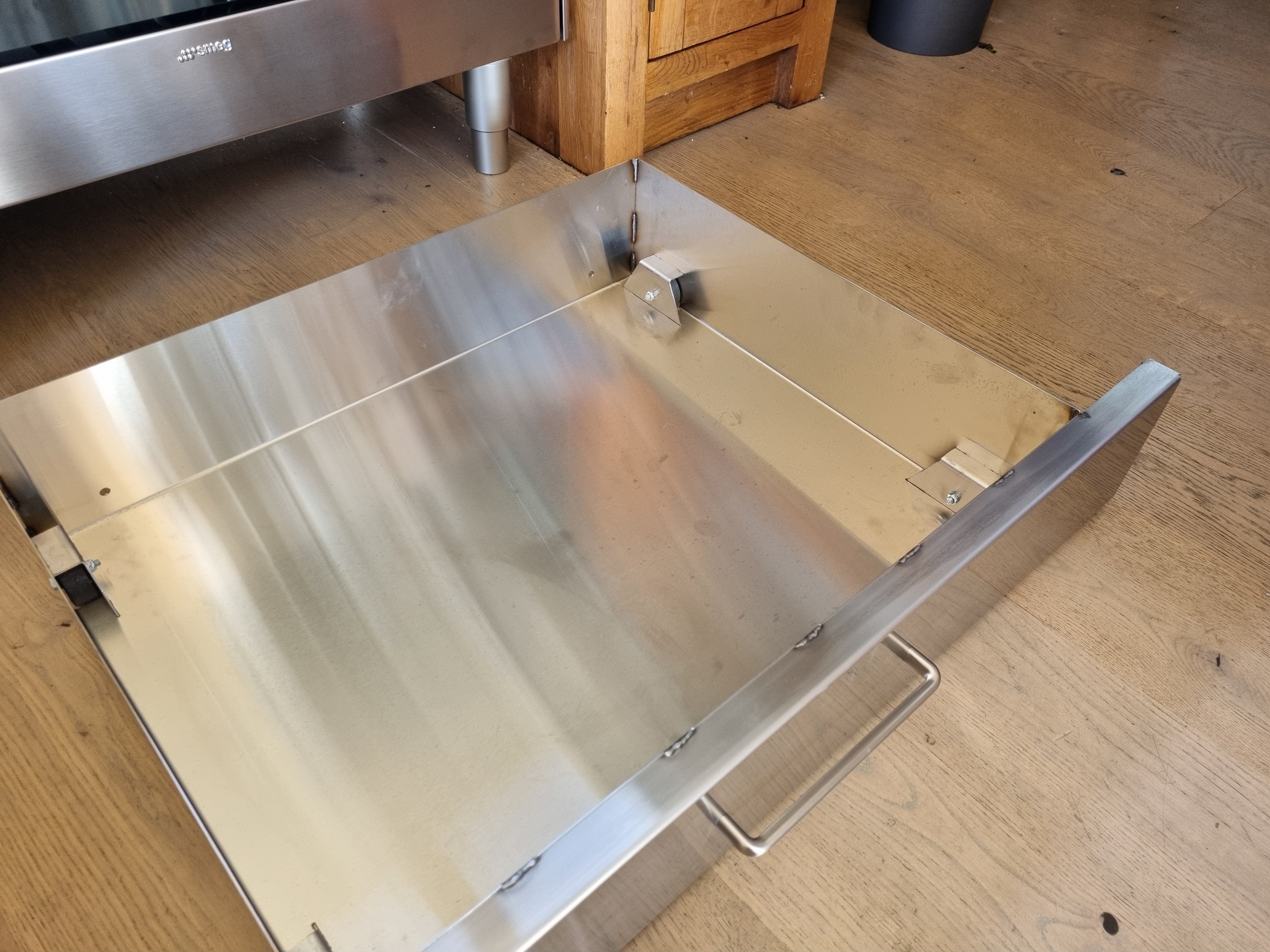
Our new oven came with a huge waste of space under it so I drew up a drawer with wheels on the corners and I got it cut and folded. Then I welded it together. Its designed so the wheel brackets slot into the sides and base but it doesn't need welding, that way I can change the wheels if I ever need to.
2 points
-
I think so, if it's the original. There won't be that many around that don't need work.2 points
-
A friend of mines old man pretty much told me to suck it up and pull the motor and he's got a guy that'll hone/plane/sort the block n head, so will get that under way if I don't find a like for like replacement soon. How did I end up rebuilding this bloody motor2 points
-
I drained all the coolant out, took the radiator and pipework off and flushed the whole lot through until only clean water flowed. Let it sit in the sun while I did other jobs and gave the engine a couple of short 30 second runs to help dry it right out. I left it at that and decided to sort out the idle control valve that wont shut completely. I started by removing it and putting it somewhere it'll probably just collect dust for a few months and then maybe get sold/thrown in a bin. I then took Hannah on another exciting date to the local wreckers where we looked under many bonnets to find a suitable replacement. 'Automotive foraging' I like to call it. Here I am in the wilds of the wreckers... I took home a couple of throttle bodies with valves attached. One from a Mazda 3 and the other from a Mazda 626. They had almost identical iacvs but one had an adjustment. I cut a section of alloy out of a big block.. Milled it flat and square.. Throttle bodies.. tested them with some pipe and the earlier 626 item has a similar fail safe to my now removed Bosch item, whereby it still lets air through when 'off'. So that just wont do and I have decided the keeper... Mazda 3 unit wins this competition and gets to stay in the workshop while the 626 item went in the bin. I did some more machining of the block so turning it into a ported hub the iacv bolts to, with an in and out pipe pressed in place. I made a bracket to suit the starter motor through bolts to which the aicv block bolts onto. In pictures.. Bolts onto starter like so... Ended up being not only more compact and better mounted than the old Bosch unit but with better pipe routing too. I ran the valve through some tests on tuner studio and it works really well, shuts properly and is also much much quieter , partly due to it running at a much higher frequency than the Bosch unit. The next thing I thought I'd check was the headbolts out of curiosity to see if they were still torqued up fine. I first laid out some neat material that was absorbent, but waterproof. My sister, a surgery nurse at Wellington hospital, gave it to me and said its handy stuff to have about. Certainly is!... Bolts were all fine and I saw no point in giving them anything extra beyond what Mr Honda specifies, so possibly risking deformation of the heads etc. Next thing was to sort out the electric water pump placement. Where I had mounted it turned out to make it a pig to bleed of air due to the outlet pointing downhill and I knew it could be better. See here... I removed the mounting bracket I'd made for it... Unplugged the ecu etc etc and slid the whole engine/transmission onto the the 'engine stand 2000'. This process is super easy as it can be adjusted to the same height as the big table or workshop bench and the engine slides really nicely on the ribbed sump. Then I slung it into the spare imp and tried out the water pump for size in the new location I had in mind... Cooling pipework serving the Datsun engine exit the bodyshell roughly about here... Much better position. Not only will the pump almost self bleed, being at about the lowest point in the cooling system, but I will also clear up the area of uglyness where it used to be. It also gives me full easy access to the transmission filler/dipstick. I removed the engine, put it back on the table and set to work marking out for a mounting bracket... Then fabricated this bracket.. Which mounts the pump here... New improved temporary cooling setup which filled up sweet and bleed of air easily.. Quality touches.. With the cooling system now filled with just water I ran the engine up to temp. The new iacv was working well and I was more confident in running the engine for as long as my lunchbox fuel can would allow. I kept checking for any leaks and found nothing. The cooling system was working well, the fan kicking on and off, the temp staying around the 95- 97 degrees range I had set on the water pump controller (which also controls the fan relay) and I was finally able to set the idle properly with the idle bleed screw on the throttle body - something I was not able to do with the Bosch iacv which was letting in too much air. Still no leaks. I ran it several times, let it cool down, checked it the following morning and the level was spot on. Touch wood but I think the extra heat and lack of slippery coolant has allowed the head gaskets to 'set'. Either that or maybe there wasn't a leak at all and it was just residue coolant from spillage when I had removed the top pipes to pressure test them. Anyway.. I was a farking happy bloke! (Hannah was super happy for me too) Now with the coolant system working and it idling nicely etc I had the confidence to finally give the engine a decent rev up and see what it sounds like at 6000 rpm. Hannah took a vid... I just love that sound. The overrun rasp that flat sixes make. It revs up so quick and clean (and there's no acceleration enrichment setup on the tune yet until I sort the main fuel table later on so it can bog if you snap the throttle open too quickly) Another vid I took showing the hand throttle... So far the little Mandalorians have managed to keep all their limbs in place. In fact the plenum chamber stays quite cool with the constant stream of cool air flowing into it. Their spaceship has aircon? Anyway. I was happy. The only issue was that the whole time I have been running it without any alternator so meaning the ecu is having to use the voltage compensation tables and its not really an ideal situation having everything running at 2-3 volts less than it should. I took my alternator apart again and ran through as many checks I could, following a very handy NZ auto electrical school tutor video about alternator testing online. I suspect the rectifier is kaput and I couldn't locate a cheap replacement. I managed to locate a second hand alternator, pretty much the same unit and have bought it - now just waiting on the seller to sort their sh1t out. In the meantime I got another similar alternator, this time a nippon denso unit from a Honda prelude that actually has a bit more clearance out back, but with an ugly grey painted steel cover. I ran some pigtail connections and bolted it up, started the engine and now have charging! Yay. With things running at full voltage I tweaked the engines idle tune and cold start settings and am much happier with where I'm at there. In case the other alternator turns out to not arrive/be a dud etc I decided to give this working unit I do have a bit of a polish and paint. In pics, finishing it off with wrinkle finish paint on the tin end cover. Much better looking. I bolted it back in place and did one final run up to temp with a bit more tuning of the fuel table idle zone. I now have the engine able to idle at 650 and I could almost get a 50cent coin to balance on the plenum lid. The engine is still only sitting on the table, not bolted in place so I cant really expect it to be perfectly smooth. I think it idles a bit nicer at around 750- 800, a zone where its also running leaner at close to 14.7. Lots of time in the future to play with settings. Confident its all a good starter and idler, plus realising I'm stalling on the next stage, I have now started to take the pump controller, cooling system and temporary wiring apart. The next time it will be started will hopefully be in the Imp. Next job is to reassemble the transmission, bolt the lot into the spare shell and sort out the gear shift linkage.2 points
-
Albert the NDT man in Wingate has tested the welded struts for cracks. Took 10 minutes. He has an electromagnet and a solvent containing iron particles dyed with a flourescent dye so they glow in a UV light. He puts the magnet across the weld and sprays it with the fluid. The magnetic field aligns the iron particles which you can see under a UV lamp because of the dye. Any cracks will cause misalignment because the field goes around them. So I've got a certificate that says it's passed. YAY!1 point
-
1 point
-
Some things fell out and that's ok
1 point
-
New wheels (13x5 from CA Accord)
1 point
-
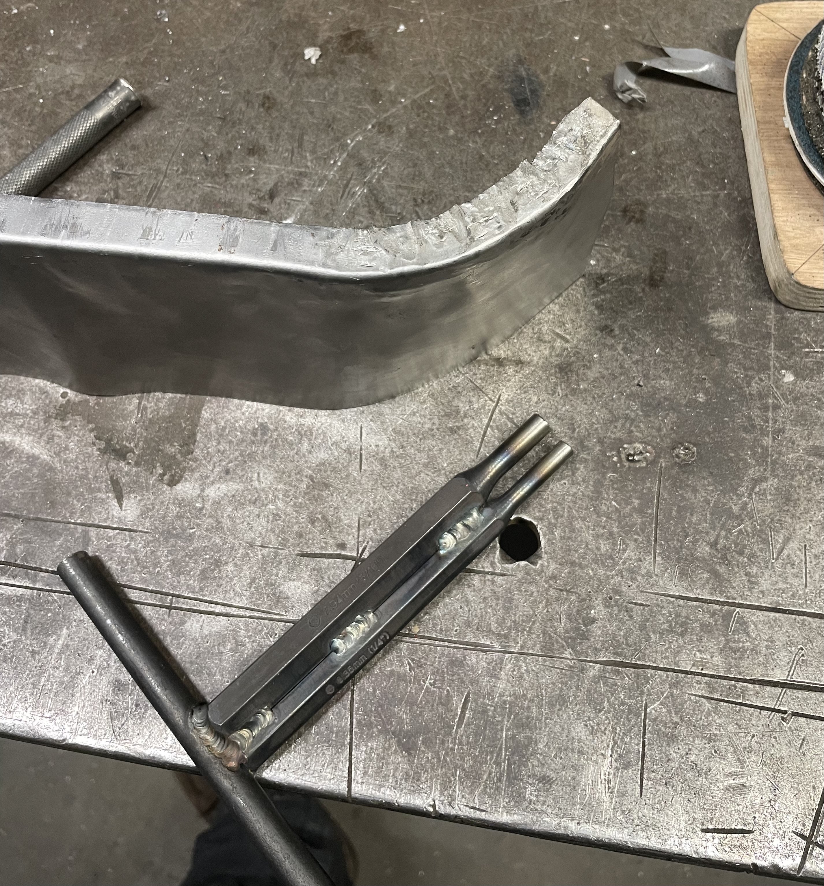
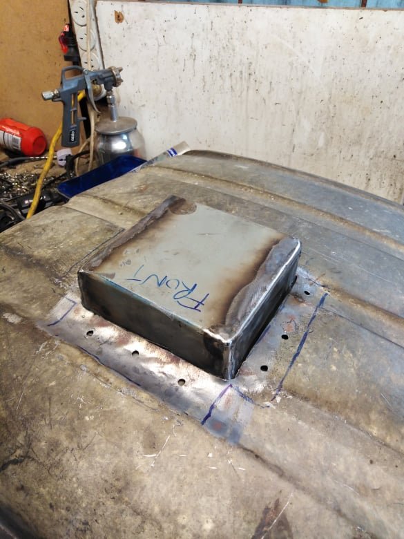
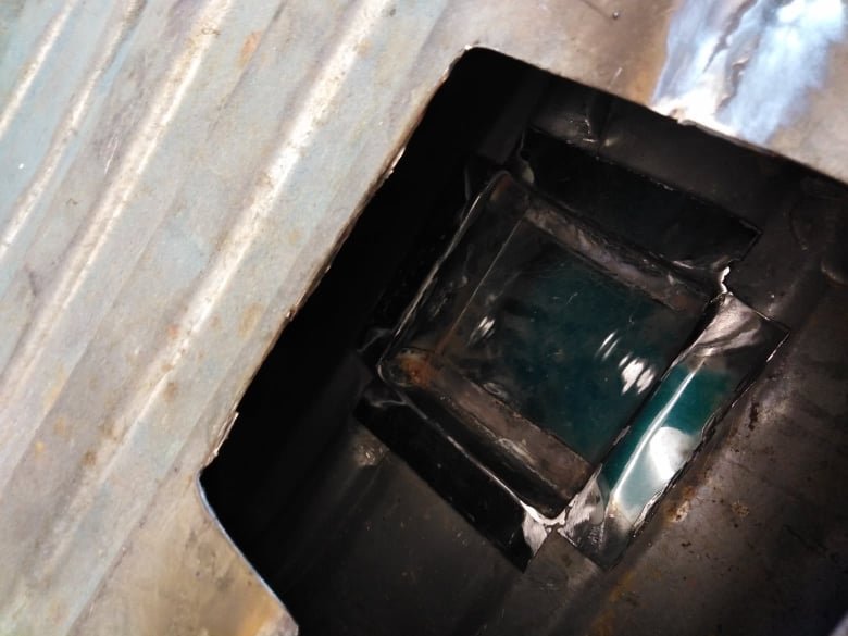
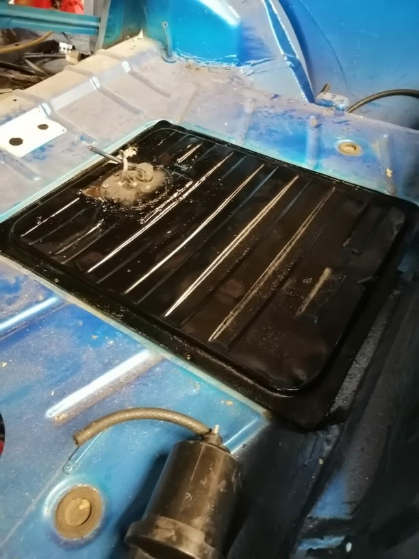
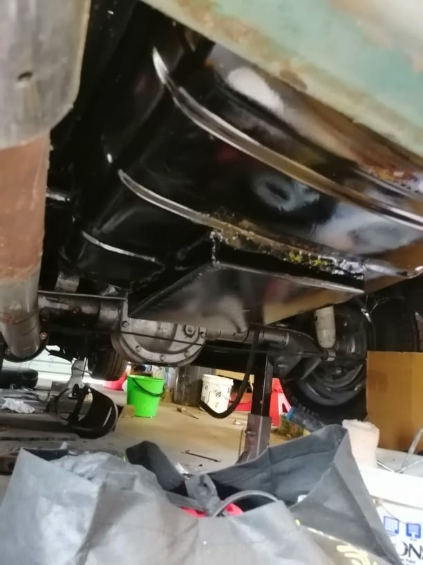
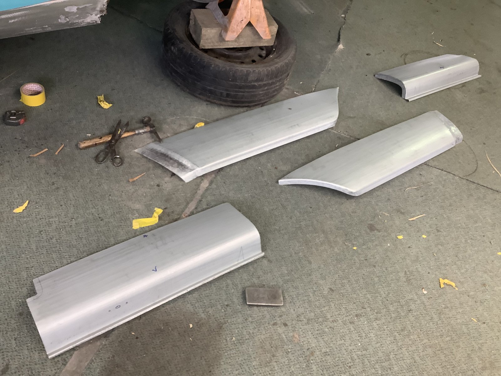
Also I needed a baffle for cornering so it would not suffer if it gets peddled hard. Since the sender unit was too tall the next step was to create a recess on the bottom side of the tank. I still trimmed the sender down but also needed about 50 mm for an area for fuel to be readily available. After getting it close took it to radiator shop and they welded it up blocked off a few holes and then I painted insides with fuel tank paint as best as possible to stop further rust
1 point
-
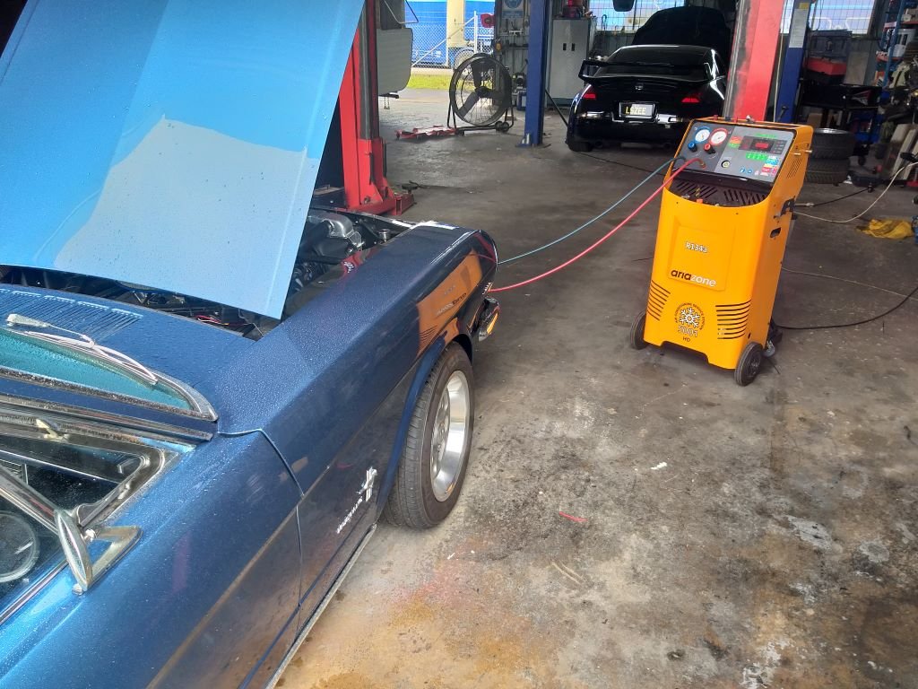
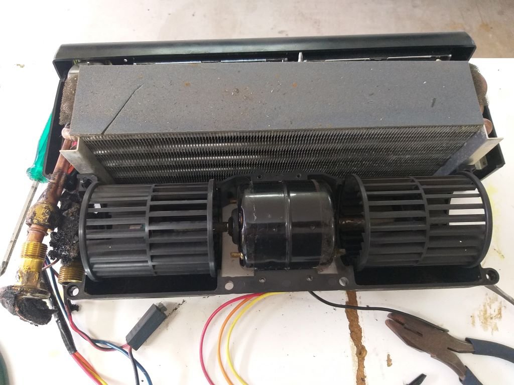
Recently the a/c blower fan has been making an intermittent grinding sound which has been getting steadily worse. I figured it was a sign that the motor was on its last legs. So, on my way back from the alignment shop I wheeled past the a/c place and Josh quickly dropped the gas for me. Oh, by the way, that black beastie in the background is an LS3 powered 350Z that is in for some a/c work. Anyway, back home I pulled the under-dash unit out and opened it up: Chucked a battery on it and fired up the motor. Sure enough grinding sound started up almost straight away. Turns out the hamster wheel on the left was just touching the inner rim of the casing. Yikes can it be that simple I thought. Removed the small holding clamp and slid the wheel slightly outward till it cleared the casing a bit more before reinstalling the holding clamp. Tested it again and it was running smooth as silk. Unit is back together and reinstalled with fresh o rings on the a/c lines and a brand-new receiver/drier. It's booked in for a re-gas first thing on Friday morning.
1 point
-
Progressing, should be painted next week.
1 point
-
I’ve heard mega squirt is the future of ecus?1 point
-
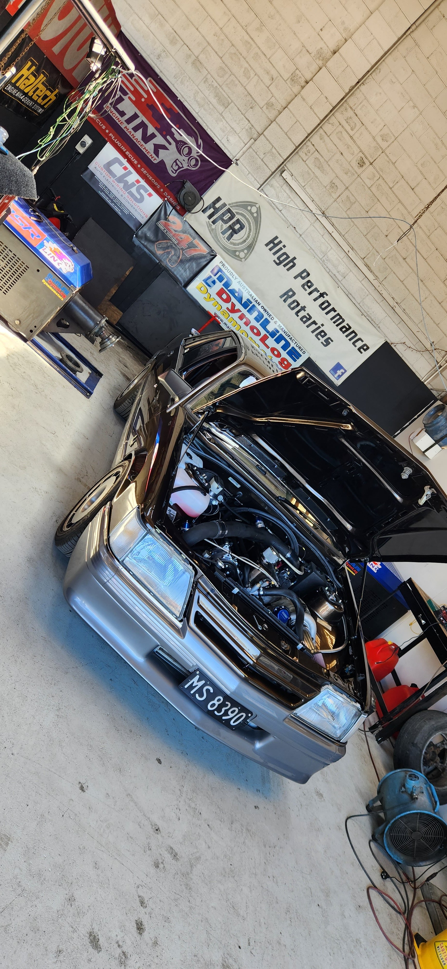
Good day on the dyno engine run in went well few teething issues with the e throttle PID control making 190rwkw just under 9psi of boost, running a bit of water meth up top rapidly dropped the intake temps from 35degrees down to 24. Will dial in some more boost later once clutch has bedded in properly. Time to get a wof tomorrow and enjoy it.
1 point
-
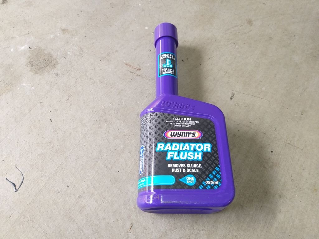
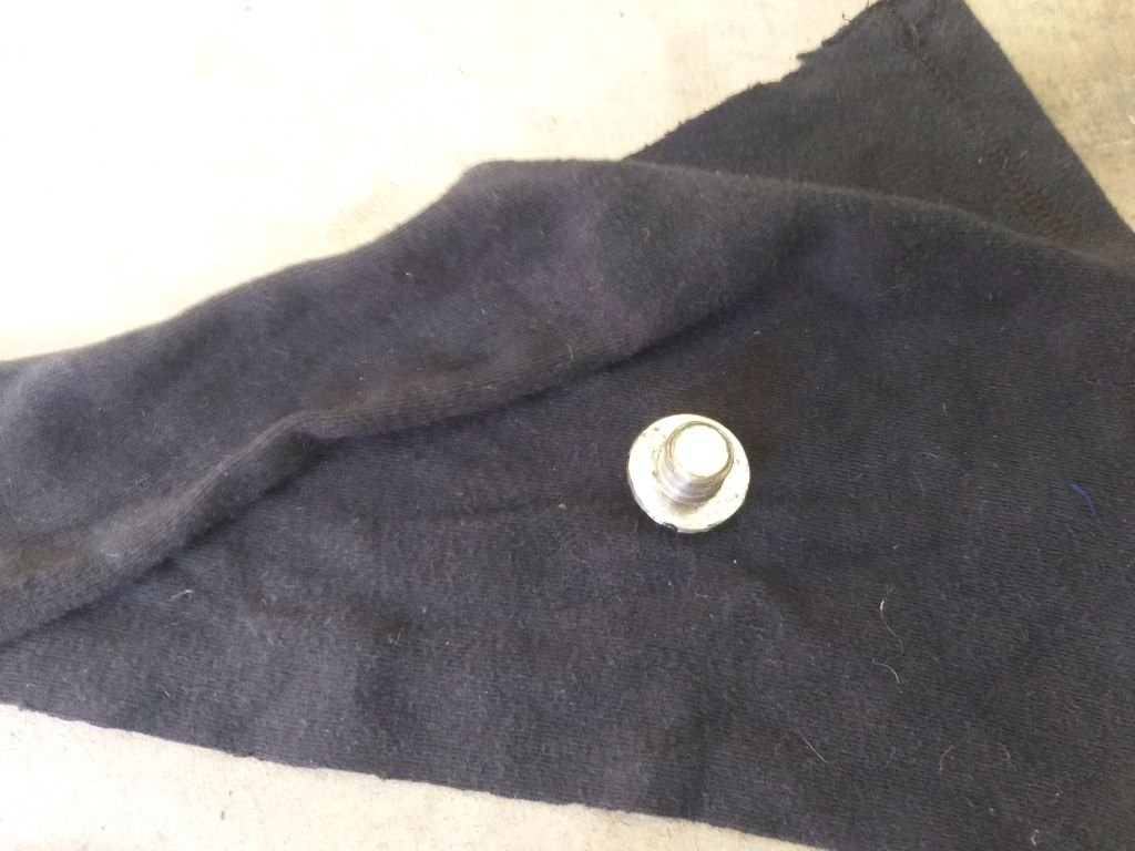
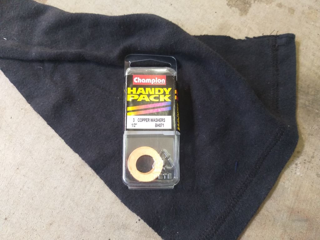
Put the Thames through a few more heat cycles this morning and still no coolant drip. Flushed with success I thought I'd give the system a spring clean: Hope you noticed what I did there. I'm just so funny ..... not. Anyway, after doing that I figured I'd tackle another little leak, but this time of the oil variety. Again, tell-tale signs of a little drip, nothing alarming, but enough to be annoying: On closer inspection it looked like it was coming from the sump drain plug and since I've now got 1000 km on the freshly rebuilt 3Y I figured I'd do an oil and filter refresh while I'm about it. Pulled the sump plug and yep: No sealing washer fitted. What a numpty I am. I've got this pack of appropriately sized copper washers in stock, so I'm going to give one of them a go: I'd also picked up a new filter and some oil on my last town trip, so everything was good to go. And that's another job jobbed.
1 point
-
Mirrors and monsoon sheilds on. test drive to try and sort a few noises out
1 point
-
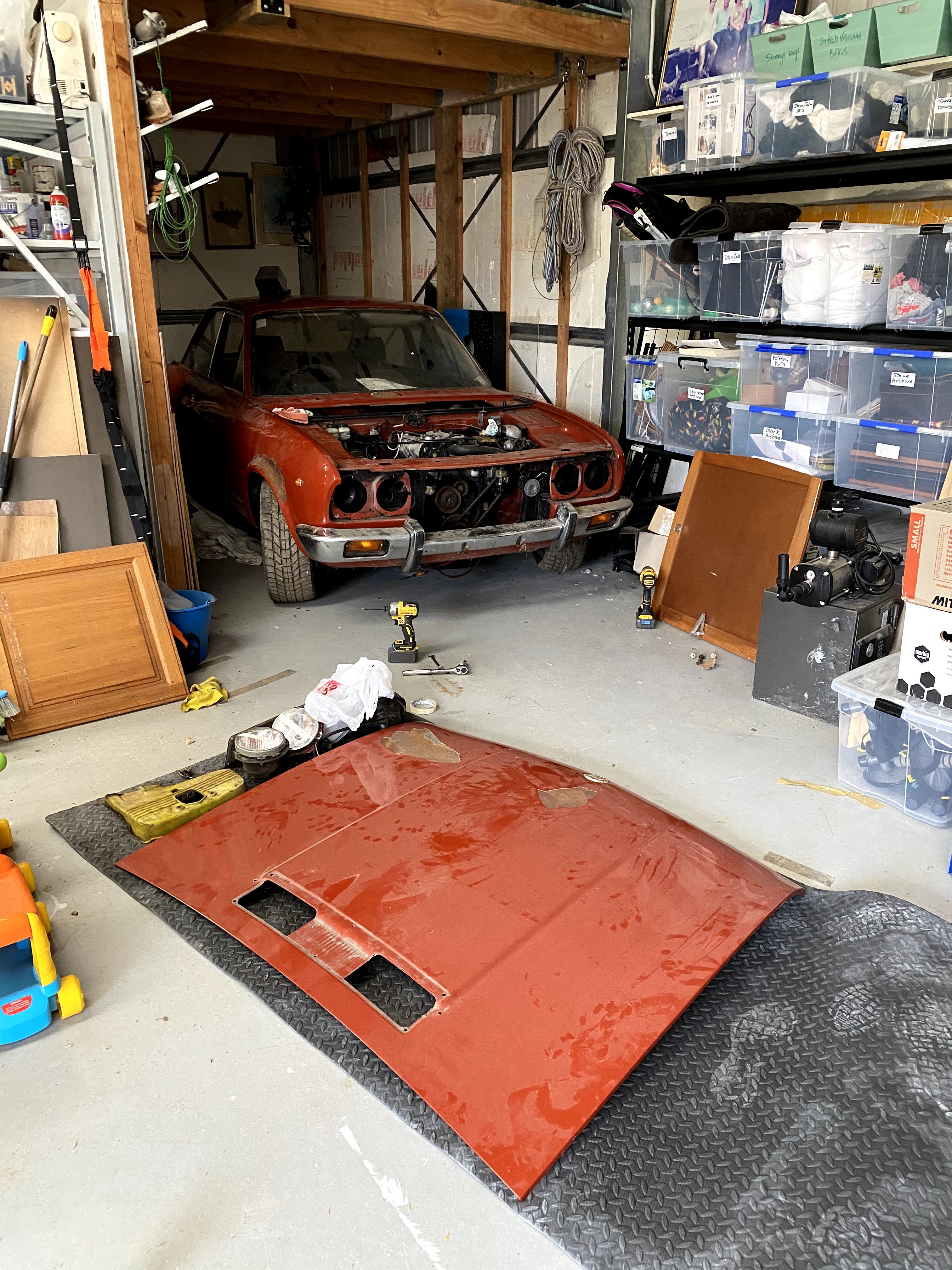
Well, here's that build thread you were asking for haha. Long story short, caught wind of a lovely old chap needing to move this cheap as his house/garage had been sold. Has been sat since 1990 when it got its last WOF, rego on hold etc. Bit of rust in the passenger footwell but nothing terminal so far. Photos of where it was liberated from; Me crawling around it (Yes I also bought that amplifier) The previous owner said it wasn't parked up for any reason but we'll get into that. SITREP; motor seized, clutch master zero pressure, brakes similar, all hoses/fuel lines are brittle. Did some mean things like push it and grab a gear, rock it violently in gear with a couple lads but she wasn't budging. Got it on a trailer and hid it at a good friends house in the wood shed; After letting it sit a couple weeks with penetrant in the cylinders we tried to give it a nudge again, but no dice so I decided to pull the head. I'm not your most mechanically inclined but I can follow instructions. Those eagle eyed viewers will notice the 'keeper' clips for the valve springs have gone for a walk, I found two floating round the rocker assembly, one still half attached and the rest.. well.. I will check the sump at some point. I can't see anything bent or FUBAR but I'm no expert, keen to hear your thoughts. At this stage, I have the carbs at home with me for a birthday, then likely send head for grind/clean/etc, get the cylinders moving after a couple more weeks of soaking in ATF/penetrant, replace HG, reassemble and hope it does things. Anyway, keen to hear your thoughts!1 point
-
Had my 1st drive of it tonight that where I'm currently upto wof is booked in for Friday so fingers crossed
1 point
-
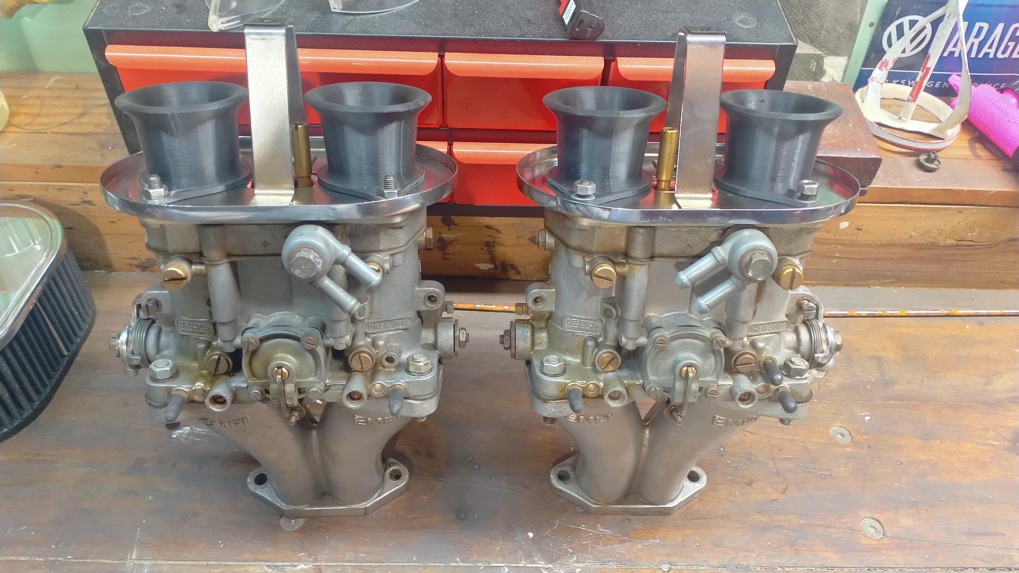
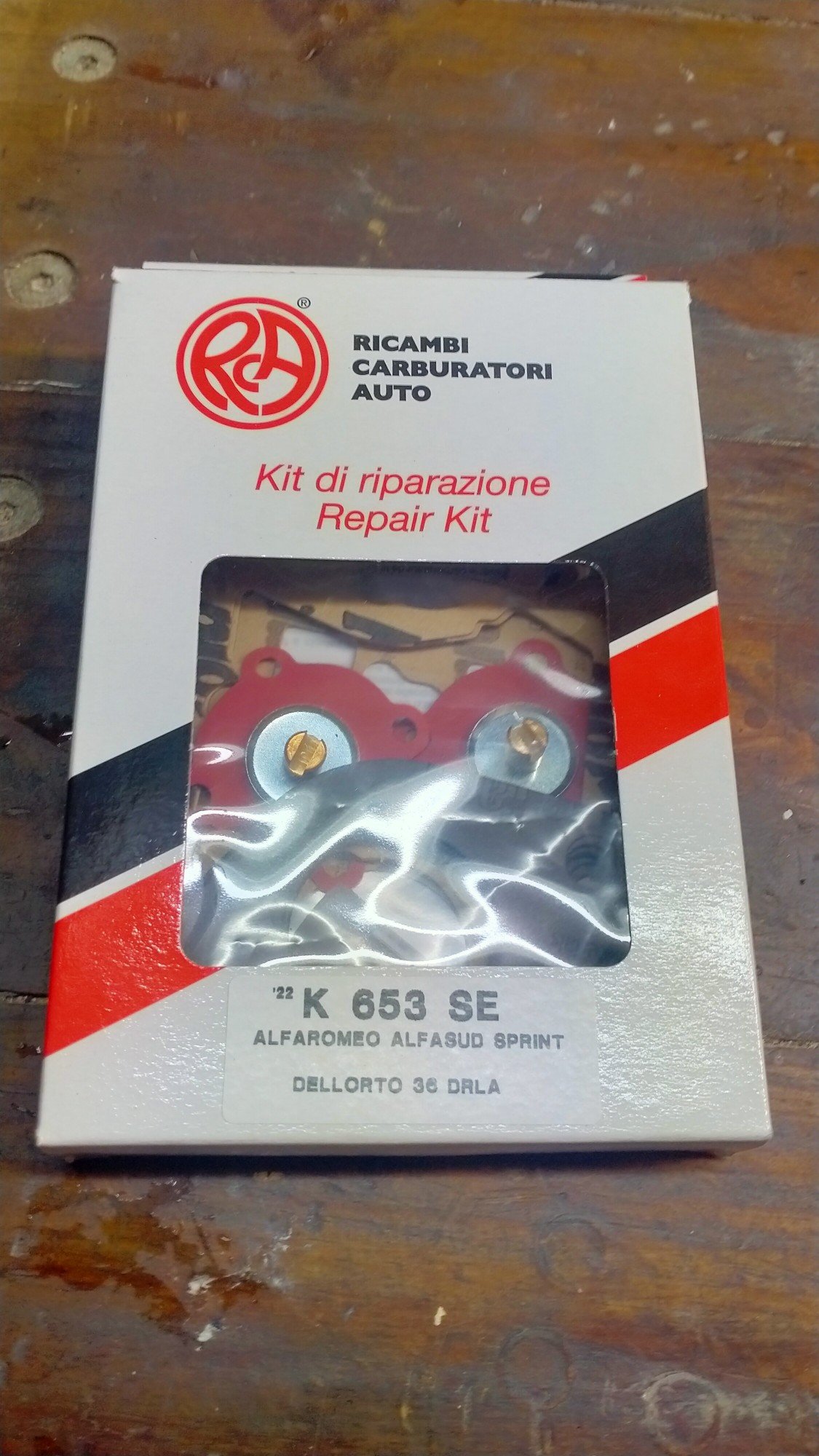
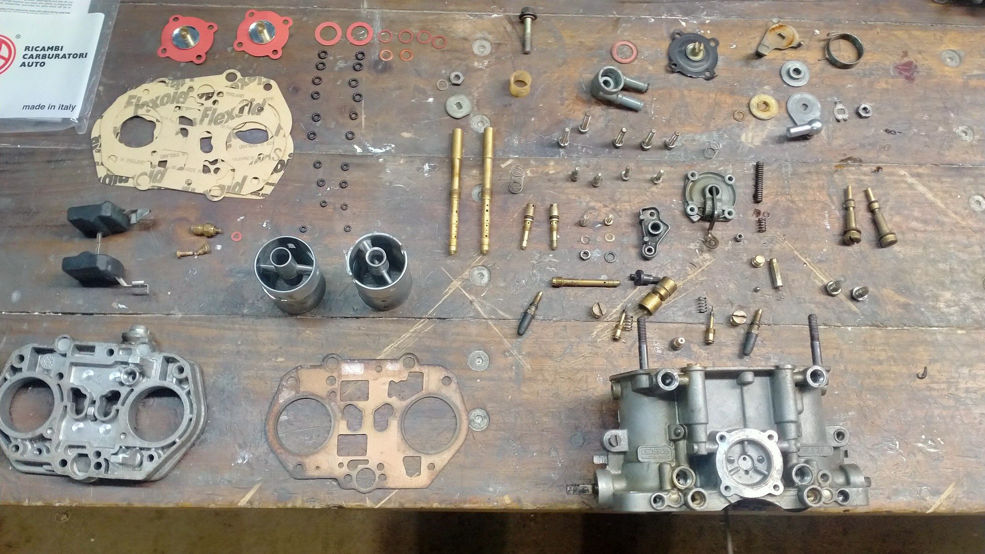
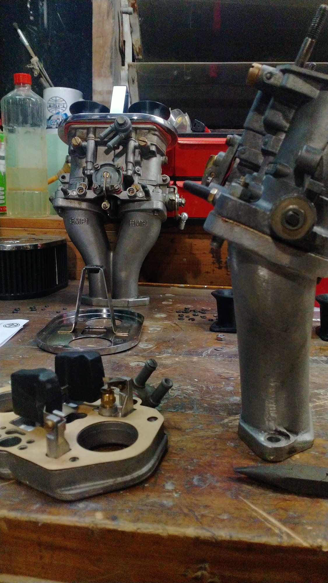
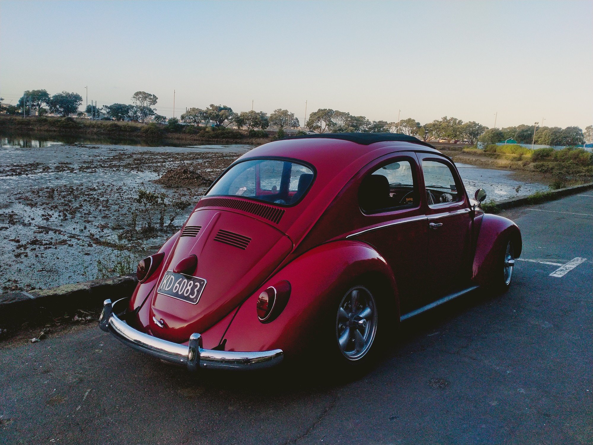
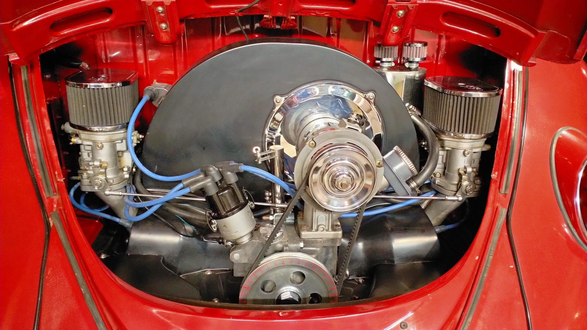
Gentlemen, after a good six months of neglect, general wear and tear I finally had time to service the VW. Living outside had not been kind to some of the so called stainless steel. Was to embarrassed to pop the hoop open at Kumeu. It been driving okay, it runs hard but it's that traffic speed, just puttering along off idle, it just didn't sound right, but fine when accelerating, something was a miss. One of the projects at work is up Silverdale so popped in the see the carb Barrys at Weber specialist, got a complete rebuild kit for the Dells. Alfa Romeo, very fancy, much racing cars. Having been through everything else the carbs are the last thing needing sorted, I don't think sitting for nearly two years on a shelf whilst I built the motor and various other life admin got in the way, helped. Borrowed the ultrasonic cleaner from work and cracked into it about 8:30, Friday night. Fuck there are a lot of very small parts in a 36mm DRLA Dellorto, and I've got two. many hours later and into the early morning I was nearly finished, didn't want to stop half way and forget where something went or lose a tiny jet. Had to stop drinking so I could concentrate! In a very rare occurrence I got to spend nearly all weekend just working on the car and not the house or the yard or visit relatives or anyone. After forgetting to tighten half the screws on the right hand carb, it started and ran pretty good. So took the time to sand back all the rust and polished it all back to a mirror finish, cleaned and wiped everything. No excuse for a ugly engine bay. Carried on adjusting the brakes, always amazes me how much a badly adjusted handbrake affects the overall performance of the old drums, seems to take up a lot of slack in the system. Popped the valve covers and set the rockers and checked the headstuds were tight still. Just need to grease and adjust the front end and actually change the engine oil and the maintenance will be up to date. Continued playing with the carbs, the access windows I put in the rear wheel wells make this easy and actually possible. I'm pretty happy with how's it's running now, so much nicer to drive, smoother, quieter better performance, more responsive. Maybe the tiniest flat spot just off idle, but nothing like the spluttering bullshit I've been driving around. Much nicer at motorway speed, just cruises.
1 point
-
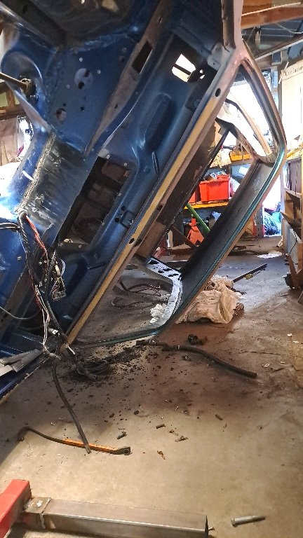
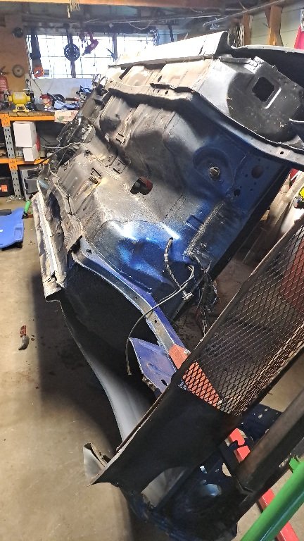
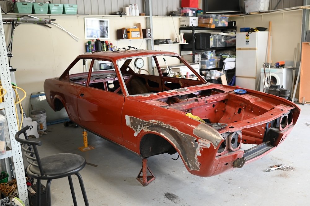
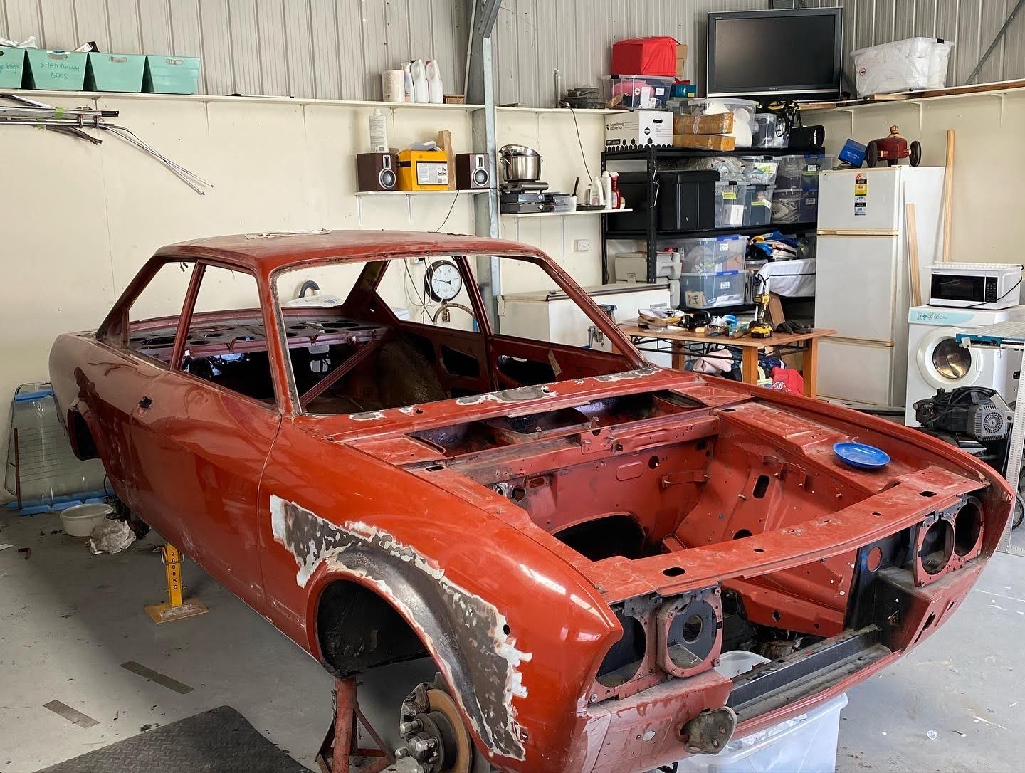
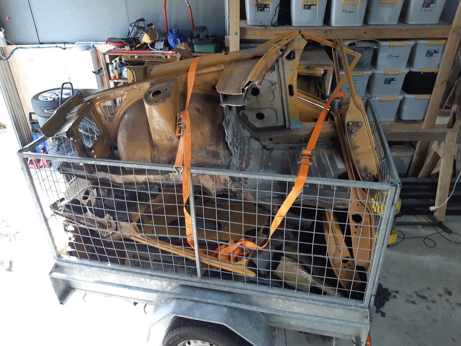
But I mean really stripped to a shell...
1 point
-
Sheesh, a lot of time has passed, and not that much has happened. Stripped to a shell...
1 point
-
Now I had an engine that starts and runs for half a minute I wanted more. I needed a makeshift cooling setup. I had a spare Nissan March radiator and fan kicking about so that was called into action. I whipped up this beautiful bit of carpentry artwork.. Using a collection of spare hoses I connected the dots between the engine, the electric water pump and the radiator... I started filling the system with coolant mixed at 35%. Remember this bit. It comes back to haunt me later. The whole system wouldn't fill up due an airlock in the coolant pipe from the opposite head. There was no way this was going to shift. The standard goldwing cooling system has both top pipes meeting in the middle at a thermostat block so they just bleed the air straight out naturally. I needed a nipple. I looked in my collection of various sized nipples and other brake fittings... Found this small nipple which was perfectly formed and a lovely size... I needed a boss to inset the nipple into. I machined one up and tig welded it carefully onto the top of the coolant pipe, in a discreet place tucked away behind the alternator so the nipple isn't immediately on display unless you look for it. Now with the nipple cracked open the large airlock was able leave via some clear vinyl tube. This allowed almost 1.5 litres more coolant in. With the water pump in override mode and twisted sideways I was able to bleed the pump out and the coolant was circulating fine. Next step before running the engine for an extended period was to sort out the O2 sensor positioning. Luckily a nice stainless boss from ali land had turned up so that was welded in place ... I was very happy that I could run the sensor cable around behind the oil filter, completely out of harms way and about as out of view as I could hope for. There's no hiding the ugly sensor sticking out of the exhaust but that's just life. The exhaust also required a token amount of silencing so I popped the old motorbike silencers outside on the truck deck and painted them with black high temp paint, mainly so I wasn't looking at ugly rusty things.. I also had to do a little bit of extra wiring. The water pump and its controller, the O2 gauge and not to forget the remote unit for the mandalorian spaceship interior lights.. I also wanted to slot my throttle cable adjuster base so I could easily remove the whole cable outer and inner without fuss... In the mill with a tiny slot drill... I made a hand throttle using a spare mountain bike brake lever and a bit of suitable alloy tube. But I needed a tiny solderless nipple for the cable end. My tray of bike cable adjusters and such what had nothing small enough so I machined one out of brass and used a 3mm grub screw... Now I had some basic throttle control without reaching over the engine. Time to start it up which happened without any fuss. The coolant system worked fine and the engine rose to temp quickly and smoothly. The fan kicks in above my for now setting of 98 degrees. I intended to tune the idle first, once the engine was hot and not using any of the warm up tables etc. But the idle control valve was still passing a touch too much air even when 'closed'. I wound the idle bleed screw in to its stop on the throttle body but still it was idling at 1200 thereabouts. If I blocked the iacv inlet with my finger the revs would drop to circa 700-800. I could also hear a very tiny vac leak from the spaceship window (plenum lid) Bloody mandalorians with their terrible glazing skills. Tightened the lid bolts down and its not bad. Main issue really is the idle valve. I might just make my own like I did with the Mazda V6. Rip the guts out from a stock Mazda item and machine a suitable body to take the solenoid and valve head. Another issue far more critical that really had me feeling quite low was this... Coming from here... Coolant gallery at base of the head gaskets on each side. It's not dripping but weeping and only once up to temp. I was gutted. I had to travel over to Nelson city that afternoon in my Imp so while there I popped into the engine reconditioners I know there and explained the problem and showed them the photos. Instantly they said I shouldn't have done my first fill with coolant. Apparently it creeps very effectively through any tiny gap before the head gasket has sealed and its slippery/slightly slimy consistency stops the paint on the gasket sticking to the surfaces. All is not lost though. I was instructed to drain the system of coolant, flush everything through thoroughly with clean water and let it dry. I did that last night. I then ran it a couple of times this morning with nothing in it for no more than 30 seconds, allowing it to cool between. Hopefully this will have dried it out and help it seal. Then I was told to just run it with water for a while and see how it goes. It might be ok. If not then they have a kiwi made product called sealwel that many kiwi/aussie reconditioners use with troublesome gaskets. He reckoned its not failed them. Worst case scenario is a pair of new head gaskets. and no coolant when setting them ! I might just order the gaskets just in case so I'm not ever in a position where I have to wait later on down the road if the above doesn't work. So yeah. I hope its ok and I've plenty of other things to do anyway. Like sort out the alternator that seems to be defective. This one. I need to either fix it or find an exact replacement because the spaceship has been built up to it and there's no room for anything bigger/longer.. I have also chopped the throttle body spring back a half coil for more tension on the throttle shut. It wasn't closing completely by itself against the strength of the engine want of air. Oh yeah I took a vid ...1 point
-
Hanging around in the paint shop, waiting for materials, should be underway soon.
1 point
-
Bench testing continued. The sump was now holding oil. Phew. I fitted the old smiths mechanical oil pressure gauge that was originally fitted in the imp race car. I mounted the gauge to the temporary coil stand. With the engine cranking over it was seeing about 20 psi. The oil level would drop in the sight glass and after a minute or two it would be back to the old level. I was happy with this. Next on the list was to check the idle control valve was working. Its a 2 wire Bosch style pwm type unit. Very common, simple, reliable and hence used often in megasquirt installs. Its basically a rotary valve that is opened against spring pressure by a solenoid windings when current passes through them. The ecu earths its ground wire in a series of pulses, the quicker the pulses the more it stays 'open'. Simple as I thought.. but.. this is where I discovered that I had bought one of the units that is actually 'closed' at about 30% duty cycle. A failsafe on cars that use these for closed loop idle control (aircon/powersteering/epic sound systems etc etc) If the valve fails then spring pressure actually takes it to a slightly open state so the car cant stall. But I'm only using the valve for open loop at start up. So when its closed I want it to be closed. Luckily I was able to pick out/burn/pick out/burn/pick out the tough as epoxy that was holding the valve stop adjustment screw in place. I wound the screw in until the valve was closed with no power. It still passes a tiny amount of air but its much better. I'll manually adjust the idle bleed screw on the throttle body to get the fully warmed up idle where I want it when that time comes. Which was going to be soon I thought! Next thing to check was that the crank angle trigger wheel VR sensor and the camshaft half moon hall sensor were both putting out satisfactory signals. Opened up the composite logger on tunerstudio expecting to see nice clean signals. But there was nothing. My heart sank. Oh here we go.. I took off the cover on the main board plug and checked the connections there. I then popped the volt meter, set at AC volts, onto pin 1 and 24, wound the engine over and got about 2.0 volts. I don't have an osillioscope and only have an old megastim 2.2 testing unit which won't create the required rpm signals I needed for testing. I wasn't quite sure what to check next so I started a thread on the megasquirt forum. Got some bits of advice but in the end I rang a mate in Richmond who has a lot more knowledge with megasquirts and has helped me out in the past. Organised to go see him the foloowing day. In the meantime I checked the hall sensor. I had never been able to find confirmative details on the polarity of the hall sensor even though it was a really commonly used unit among many a citreon/fiat/renault etc. I finally found a factory service manual online for Fiat ducatos which had a pin out of the sensor. Turns out I'd got my polarity wrong and after swapping the wires around at the hall sensor plug I now had a strong clean cam signal. I also made a mandrel to hold the old honda 12-1 trigger wheel in the lathe. Then I made two jigs. One for the spare goldwing VR sensor, like the one I'd fitted to the engine. The other jig was to hold a Mazda V6 VR crank sensor of which I had a few kicking about and had used them with no issues on the Viva. I spun the trigger wheel up in the lathe at various speeds and took voltage readings of both sensors. The readings were very similar but I still couldn't tell what the actual signals are like. The next morning I drove out to mates place and he set to work on my ECU. He compared the board to his spare Ms3x. looking for any differences. Remember I had bought this ECU secondhand from someone on trademe and was told it was working. I had swap some of the circuitry jumper wires to suit my application. Once he was happy there was nothing major missing on my board he got another spare ecu he had and ran up my sensors in his test bed to confirm they were putting out a good signal. Then we (well - mainly him, I just stood about and learned) systematically went through the VR circuit looking at the signals on his osiloscope. Discovered that transistor U7 was faulty so he kindly swapped out the known good item from his MS1 which I'll find a replacement for him. After that he found a loose, terribly soldered resistor in the circuit- when it was wiggled the signal would appear.... re-soldered that and hey presto - clean signal. Lots of other pins got re-soldered too. The Goldwing pulse generator/VR sensor puts out a much weaker signal that the Mazda crank vr sensor. we double checked them against each other and the Goldwing item struggles at slow speeds (cranking type speeds) so I'll swap over to the Mazda item. When I got home I quickly tried the repaired ecu out and now there's a good rpm signal but it drops out of sync but I took a log anyway. Then started making a new bracket to suit the Mazda sensor. New vr sensor in place and wired up. I then had to remove one cambelt, which is so easy to do on these engines, remove the trigger wheel, file off the old key and weld a new one in place to suit the mazda vr sensor position which was now bolted in the other set of holes Honda used for the original 'pulse generators' as they call them. New trigger wheel key peg.. Finishing that lot got me to this point when trying it out that evening... The red spikes indicate an out of sync situation and no rpm reading but at least the log was clean, consistant and rythmic. Something wrong in the settings, not interference. I tried changing various trigger settings but no luck I was tired so off to bed. Following morning I discovered that when I was changing the trigger settings I didn't spot the prompts to power cycle the engine because I was still on the diagnostics page. So none of those changes took place until the very end when I had actually set it back to the typical default settings. This time a power cycle after changing the capture to falling edge and I got this lovely log... Yay!!! Now I was ready to check the ignition coils and then the base timing. What else could possibly go wrong? Coils all tested fine and the sparks were nice and clean looking. I then marked the timing mark on my custom crank pulley and tested the base timing. I was out by 4 degrees. Pretty happy that I had got my trigger wheel so close. Simply changing the trigger wheel offset value in the settings by 4 degrees had the timing marks line up bang on. Engine start up time was here! I went to bed happy, excited and somewhat nervous about what could happen, or not... So this morning it was time to roll the engine out on the table to the front of the workshop, throw some fuel into the mix and see what happens. I set up the garden hose just in case, taped my phone to a light stand, started recording, tentatively went for a start and this is what happened... Wow!!! Faaaaaaaaaaaarking awesome! What an occasion. What a milestone. Such relief and much giggling with joy. I couldn't believe it. First start on my own custom built engine and it sounds bloody amazing! That was starting on a basic universal base map loaded onto the ecu so I was really expecting a lot more mucking about with the starting settings to get a clean start. I was stoked! I tweaked the cranking settings slightly and now it would start on the button after a few cycles... I can only run it for a few seconds as there is not a drop of coolant in the engine. So my next job is to set up a makeshift coolant circuit using a spare Nissan micra radiator and setup the Davies Craig electric water pump. I can test for leaks and then I can really have a good crack at setting up a nice clean starting and idling tune. I'm so happy! Alex.1 point
-
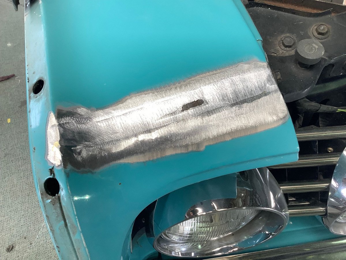
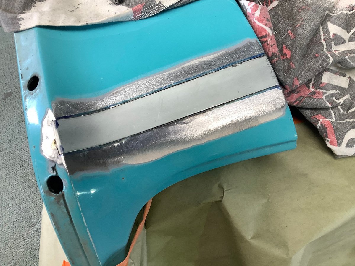
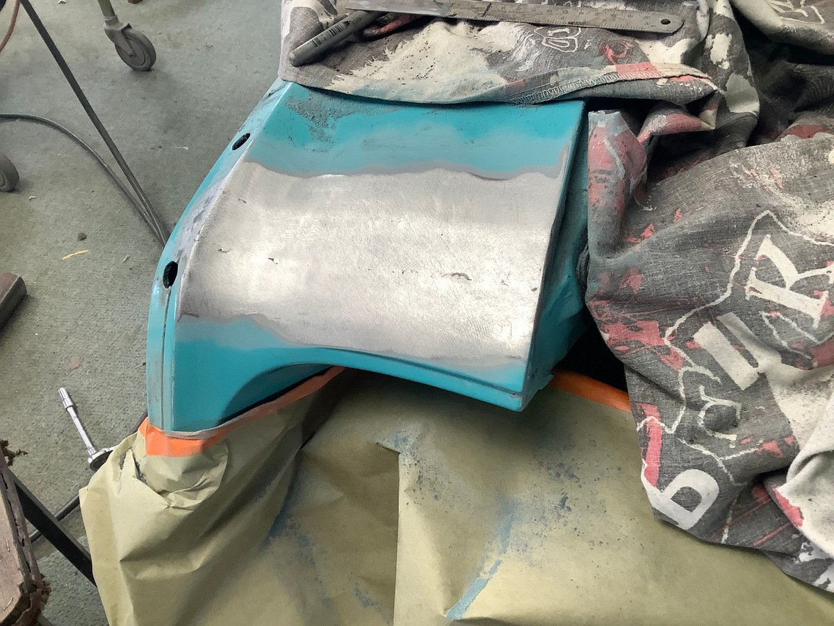
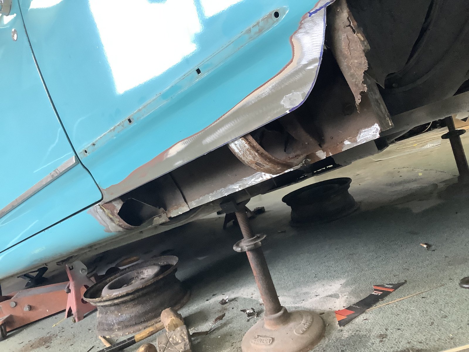
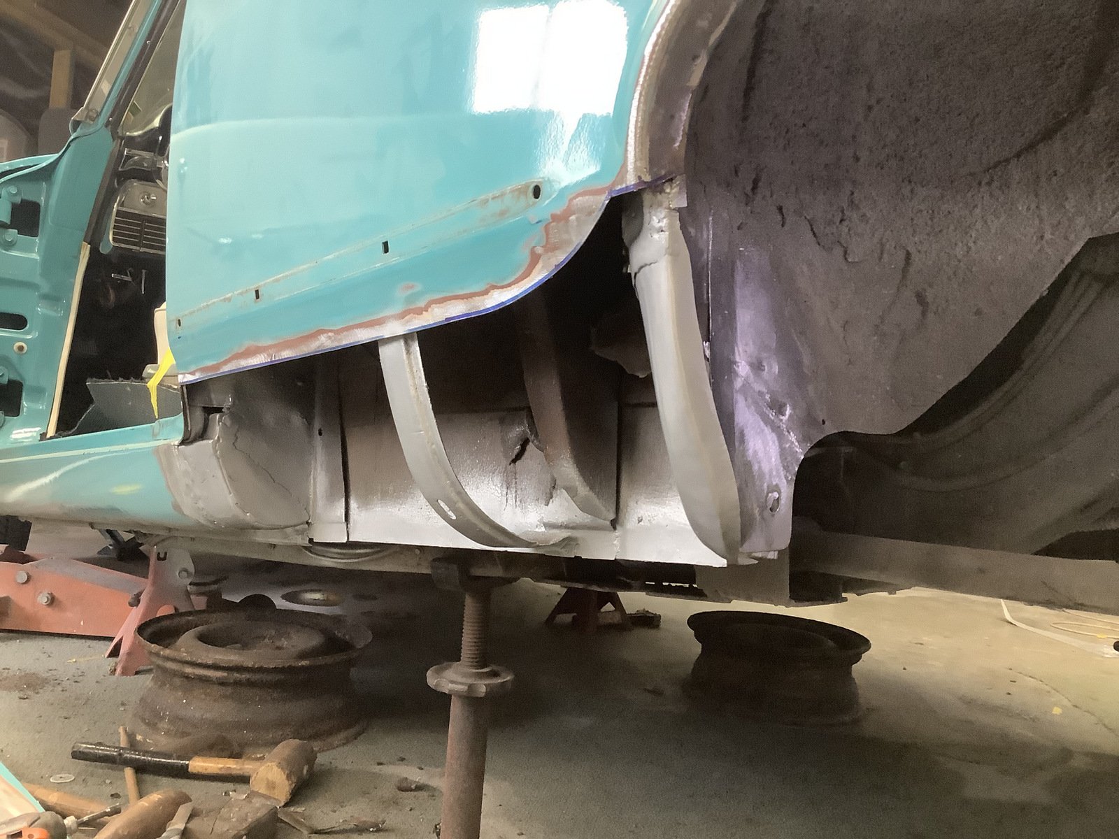
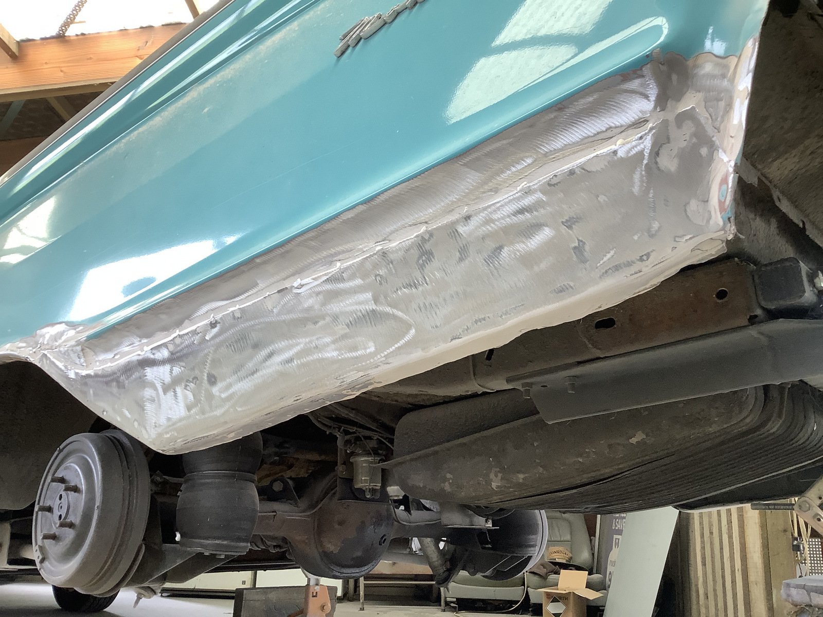
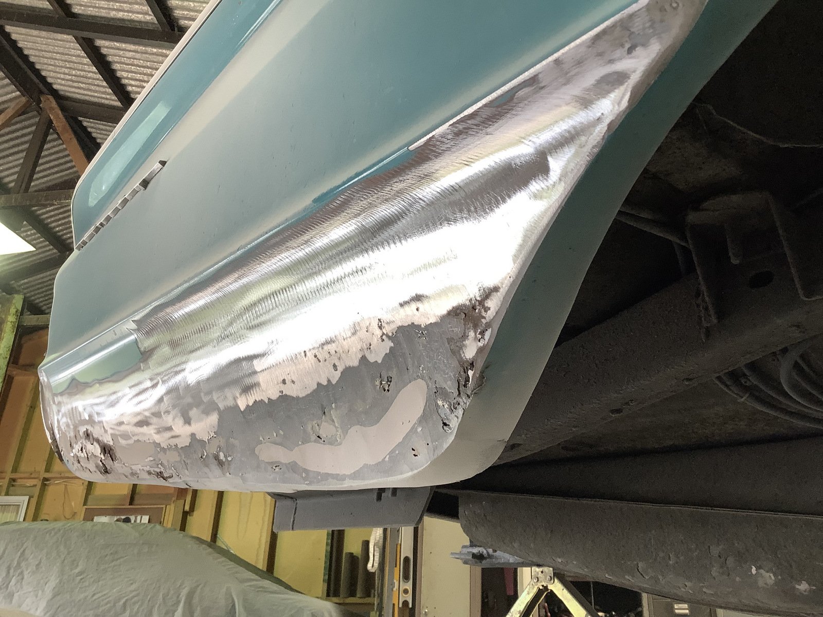
Rusty rust rust. The leaded seam between the guard (probably the same pressing as a Galaxie) and the headlight peak was going bad on both sides. Seam cut out and replaced
1 point
-
More more more
1 point
-
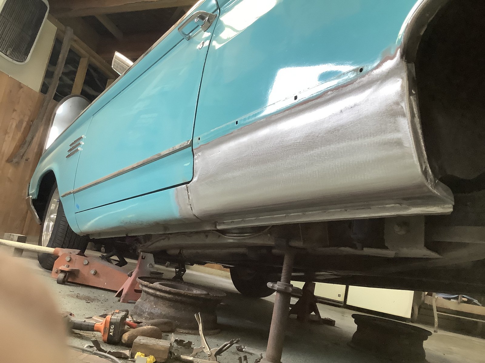
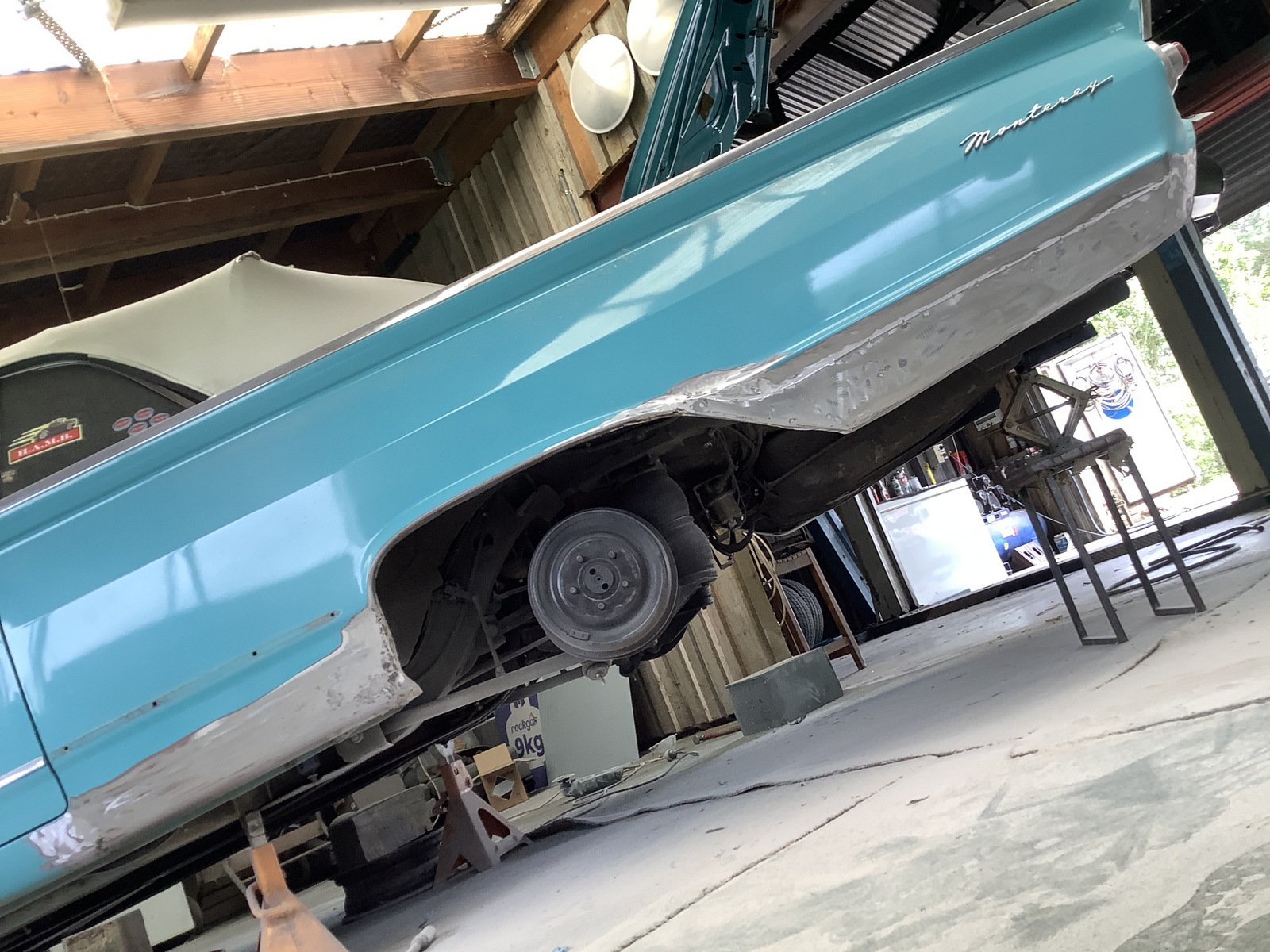
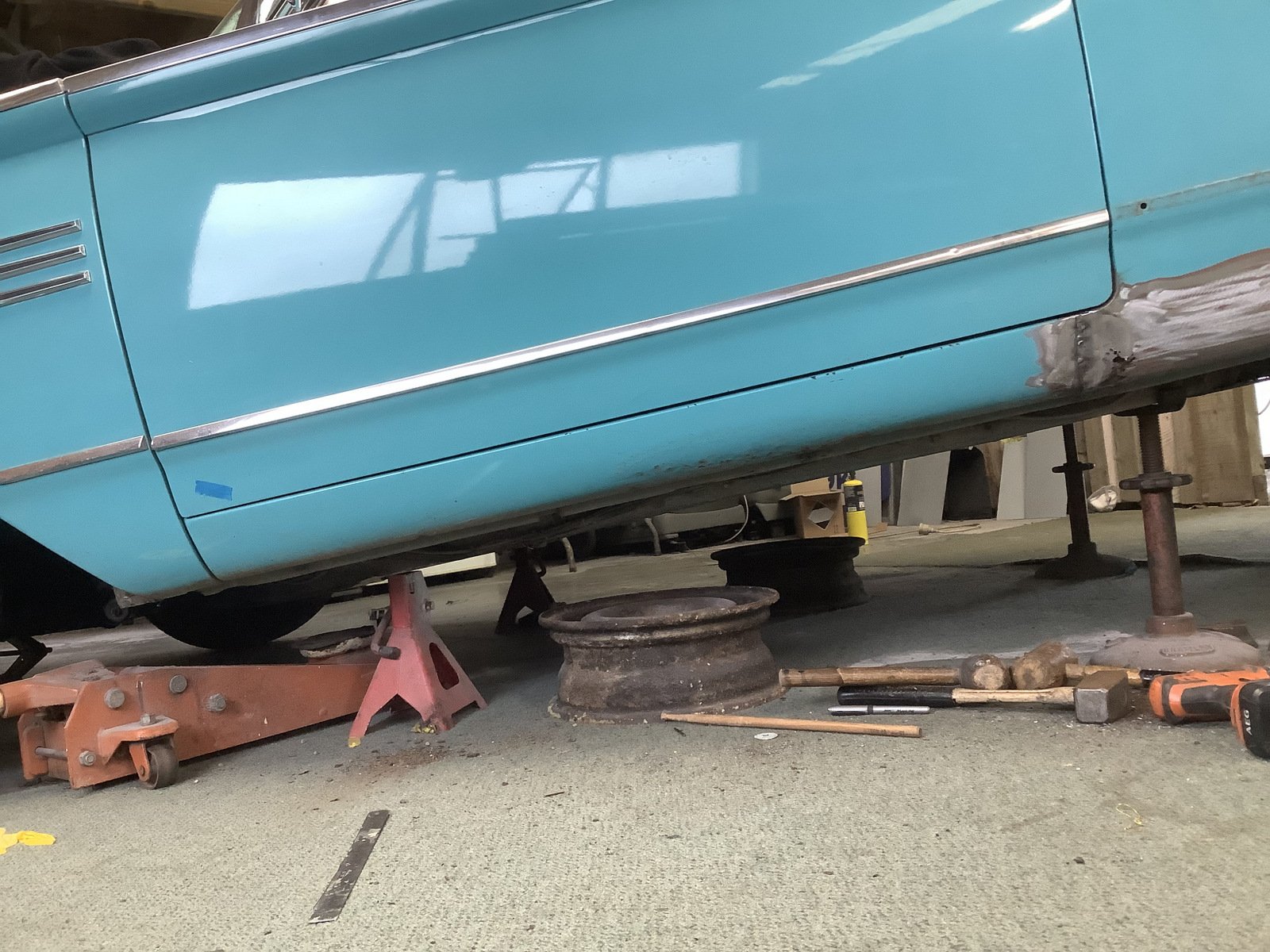
Mercury has been sent up the road to Mercury Garage for some derustification Lower rear quarters, sills, front of rear wheel arches, gas tank support are the main issues
1 point
-
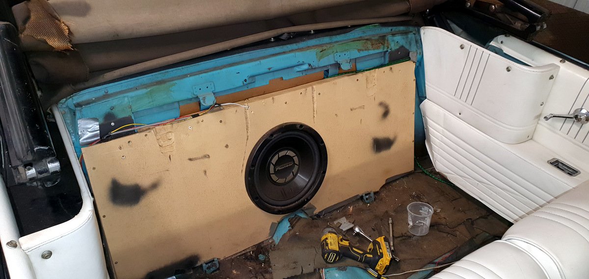
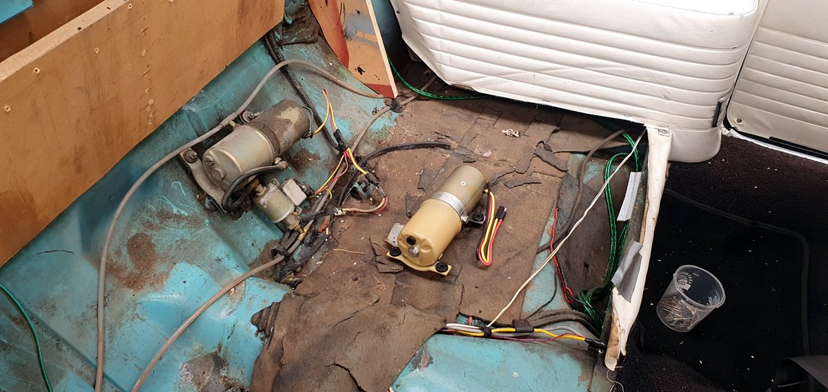
Post Beach Hop update (couldn't go in November 2022 sadly) At the end of January, the convertible top stopped working, luckily in the garage. It's been getting slower for the last couple of years I suppose. The hydraulic pump lives behind the back seat, unfortunately also behind the subwoofer back there. I checked with PG Hydraulics who basically said that if the wiring is OK, just get a new pump as they are not easy to get parts for. The pump is fairly common to many US cars of the era. Northwestern Ford had one in stock which seemed the best option given the weight and timeline. Old vs new. Swap over went OK except for an incident with the rubber bung popping out while cycling/bleeding the system which made a bit of mess. Also did a bit of a service - oil + filter and grease gun session underneath. Drive up/back was fine, no issues. Beach Hop itself was fun as usual The rebuilt booster has never been quite right, with an audible vacuum leak when applying the brakes. I've been igoring it as the car has mostly been stored down the road in a chicken shed for the last year. But tonight I bit the bullet and pulled the booster out again to send back to CBC for them to look at. Getting it out is fairly easy, getting it back in and connected to the brake pedal is a ballache.
1 point
-
Not been able to do too much on this over the last wee while. I do still really need to get the bumper fixed and repainted. It really throws off the look off the car and make it looks a bit rougher than it is! Something that was still bothering me was the clutch slip at 20psi... I had a mate ask me if he knew of anyone looking for a tilton twin plate clutch setup (less discs) so I thought, bugger it. Me! Acquired some springless clutch centers from Barry Manon at MRP. This car won't see much town driving, it's meant to be a fun car so know that a clutch with no springs is not fun. Anyway, the setup looks similar to this: clutch by phillipbaines, on Flickr I had a weekend with nothing on and woke up and felt like removing the W55 from the AE86 would be a good idea. I'd mentally prepared myself for a frustrating day which is exactly what I had but it all went well in the end! new flywheel installed 20230205_123632 by phillipbaines, on Flickr I'm a numpty and didn't take a proper after photo (probably due to the amount of fun I wasn't having) so here's one of me checking that the spline is aligned between the clutches properly. The first time I tried I didn't get success so it had to all come off and go back on. Anyway, that was done. hooray. 20230205_132927 by phillipbaines, on Flickr I've also grown up since I was 21. 7 years later i've come to the realisation that low boy life, is not fun. It's annoying. I don't like going sideways over speed humps, and I don't like losing exhaust v-bands on 100km'h roads 15 minutes in to a journey. So i got a pair of 15 x 8's (something like -25 for the rear, +10 ish for the front. can't remember) paired with a set of Nankang AR1's. I had this thing at Manfield for a bit of a bash a few months ago, the Toyo T1R's were definitely not up to the task of keeping rubber in tact coming out of the corners leaving me pretty unconfident to push it too much So, tyres/wheels on. Ride height increased by 10mm 20230206_132902 by phillipbaines, on Flickr 20230206_132918 by phillipbaines, on Flickr 20230204_174851 by phillipbaines, on Flickr So, done for now. Took it for a drive. adjusted the clutch pedal, clutch is actually fine to use and didn't find it too terrible. Just need to downshift on gears which is easy enough! TODO (more for me to remember): - Adjust pinion angle - Acquire adjustable lower arms for diff - Fix bumper - One day: Find some 15 x 8 long champs in perfect offset. This is a low priority but they just look so lush on longchamps Discuss:1 point
-
Julian wanted me to plate over the butt weld.
1 point
-
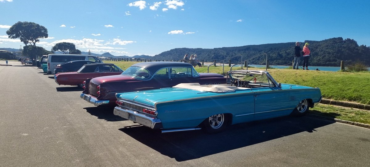
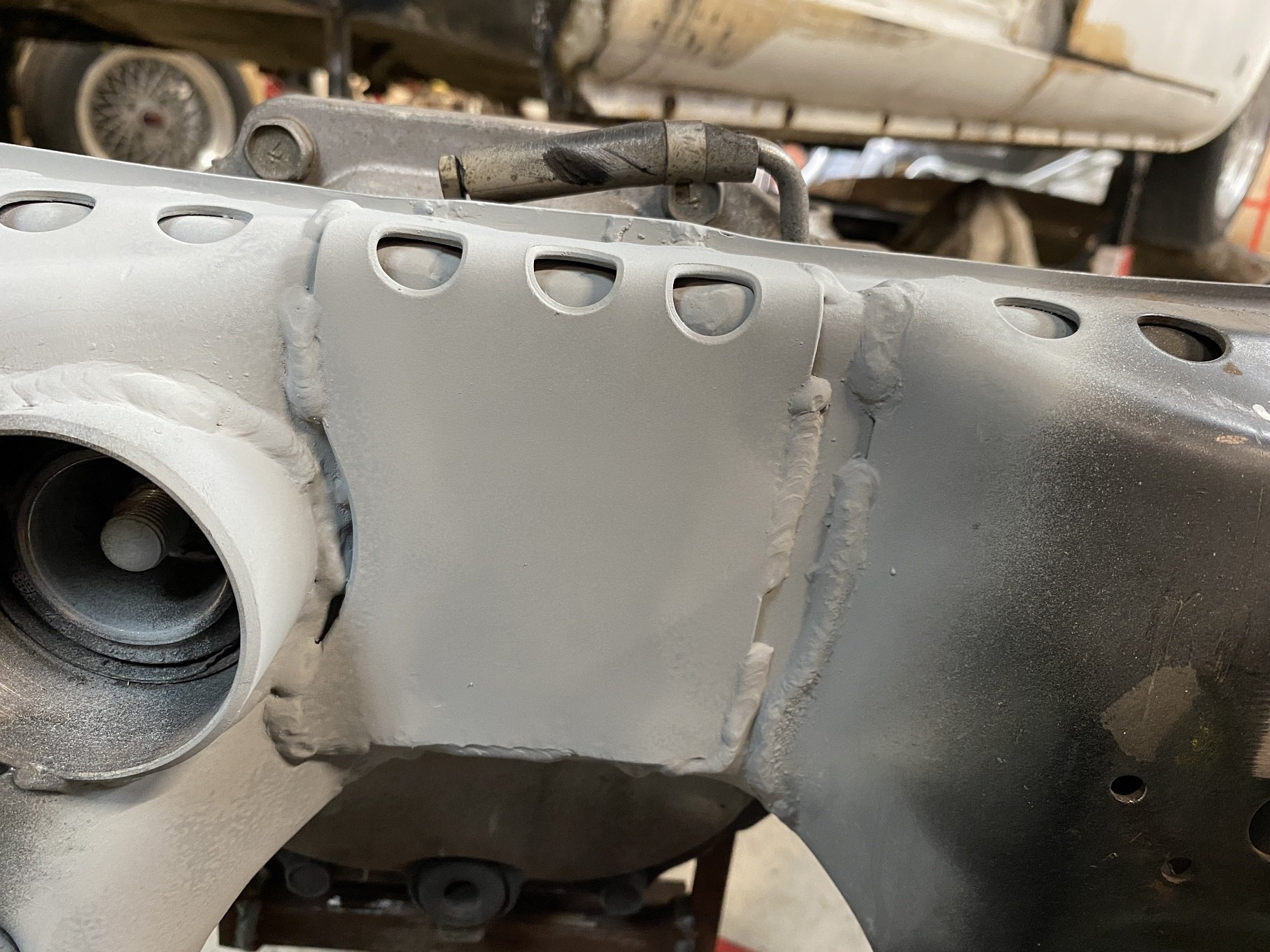
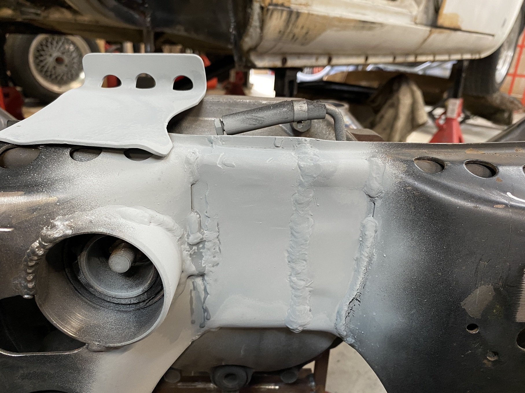
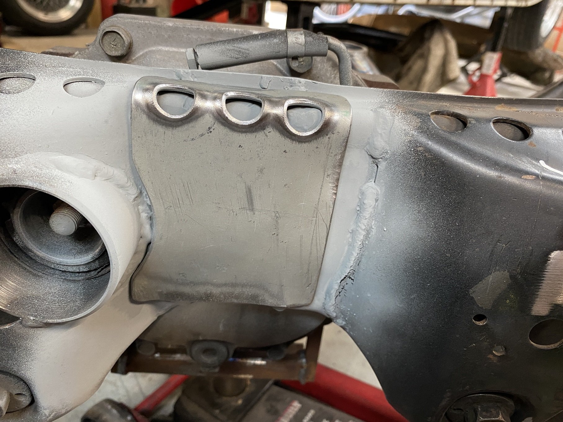
Post a few weeks, driven it a few times and oh lordy. once the boost kicks in it's an absolute rocket. Definitely looking forward to driving this around more post cert Time to reset and get some of the small issues resolved Glenn at Syndicate Fabrication on the tools this week geting these issues sorted for me I always had an issue where the o-ring would leak fuel out of the fuel rail so definitely wanted to move to a welded bung either side to save me the stress of thinking I was dripping fuel out leading to a kaboom under the hood Then it was time to get the oil filter relocation sorted: One full hand worth of space (i'll still get a plate made up to go over it in case of giant stones) The hole for the oil lines will be filled with something similar to this to help clean it up a bit: https://www.mnpctech.com/products/pc-cable-grommet-large?_pos=2&_sid=21c8d58cb&_ss=r&fbclid=IwAR0vvx0Esgd0kWQ9Wu75g8tsqxPeL1_BoJuKxpY8nZG8PoZhAJKR30qFDrg Will be attacking the oil catch can recirculating into the turbo + driveshaft hoop next1 point
-
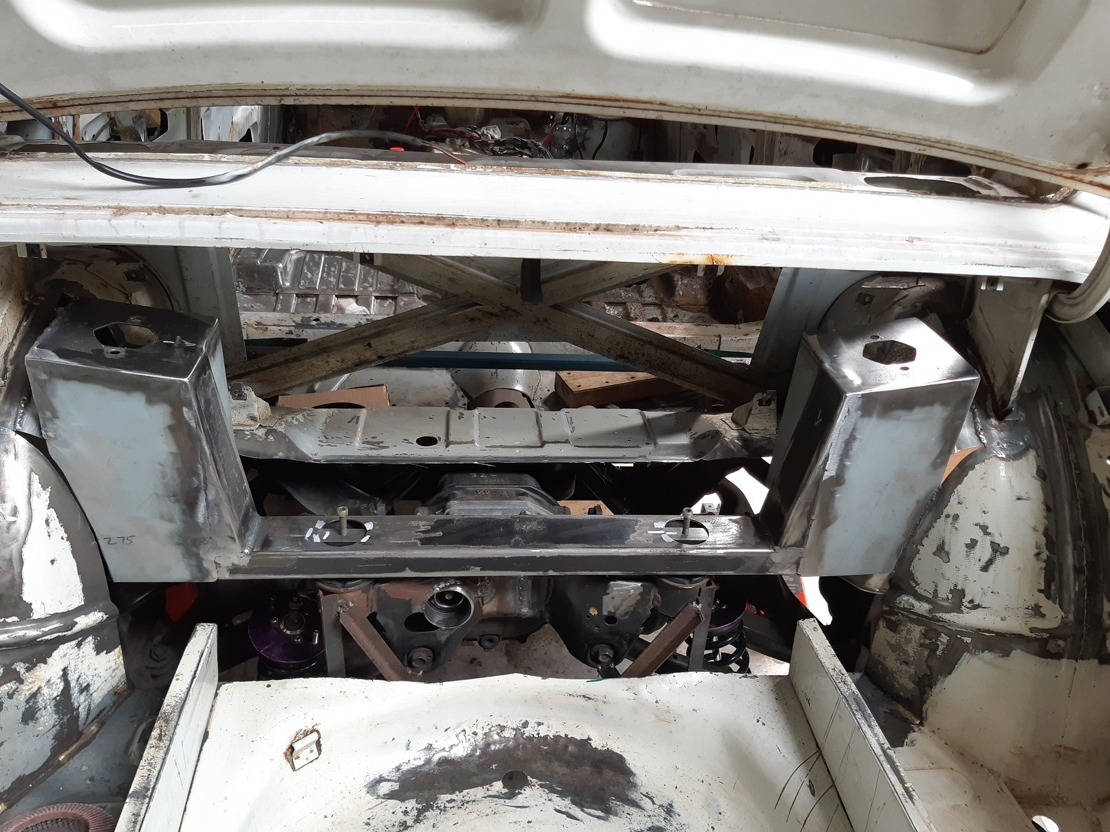
Got good news from LVVTA today. My suspension/steering modifications don't meet the threshold to require design approval because the geometry is still OEM nissan/triumph. The suitability of the floor pan mods and mounting can be determined by the certifier.1 point
-
Both sides done now. I also removed the brackets for the fuel tank. I'll use straps for the new tank. Old one won't fit anymore. New one will be about 65L, hopefully big enough.
1 point
-
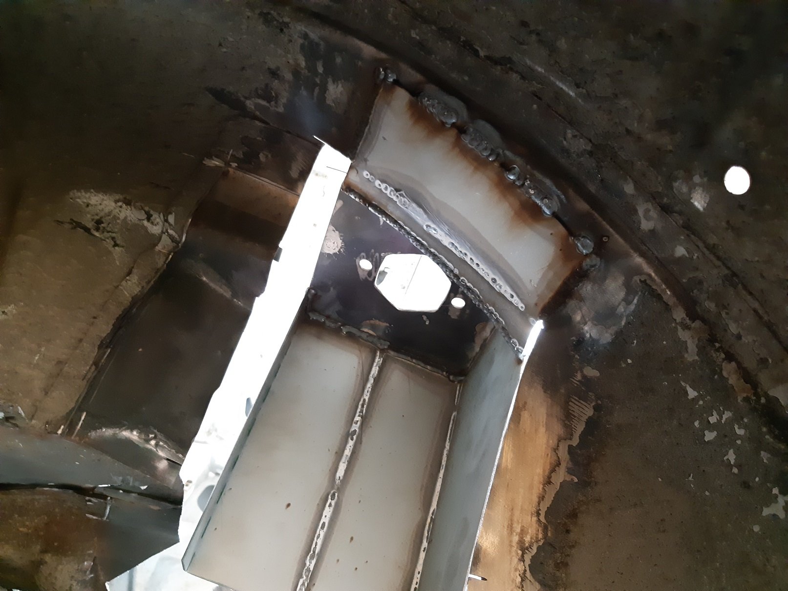
Well, the rear mounts are in. Already feels pretty solid. The boot hinge brackets are probably helping too since they tie the top of the wheel well to the boxed in section of the parcel tray. Still some more welding to do here, I haven't finished welding the back side of the corners, which I'm doing so I can linish back the weld on the visible side. Then all the big gaps to span and some plating. I'm using 1.6mm for both.
1 point
-
Like a glove.
1 point
-
Ok finally a moment to continue pulling things off the car #timepoor.
1 point
-
Howdy fellow isolated friends. I got my crossmember adjusted for my W55. I couldn't figure out where a vibration was coming from and narrowed it down to the driveshaft. Doing a UJ angle check I got it pretty much dialed in with spacers under the box to get it 2.5 deg on both ends, then got the member remade to sit where the spacers took it to 20200221_105825 by phillipbaines, on Flickr I made a patch harness by cutting a plug out of another small port ECU. Got the Link to fire up the motor and had the timing set. I did't have time to get it tuned for Toyota Fest so ran the old ECU down. Least I know that I can start having a play with the Link once I have some time... like ISOLATION TIIIME! 20200223_195148 by phillipbaines, on Flickr before the lock down we were lucky enough to head down to Toyota Fest for the weekend and what a treat that was. Such a good event and so grateful that Toyota put it on for us every year. The car drove down with no issues at all, and drove up with no issues at all. I couldn't believe it! Thrashed it around the track, thrashed it coming over the pass to Cromwell. drove it home easy. 20200307_123559 by phillipbaines, on Flickr 20200307_151653 by phillipbaines, on Flickr 20200307_153252 by phillipbaines, on Flickr Now that i'm back i'd like to increase the drivability. I've installed the A/C compressor and A/C lines again, once the lock down is lifted i'll buy a new O Ring kit so I can put the new AirCon gas through it (i watched a YouTube vid on how to do it.. wish me luck!). (no photo, oops) Added some conduit over spaghetti junction under the guard, surprising something so little/cheap can make things 1000x better 20200326_123514 by phillipbaines, on Flickr Before the lock down I went and got some offcuts of underlay. Shame, I just missed their dump of proper big sized pieces but ah well. chopping and sticking in puzzle sized pieces will still do the jerb. 20200326_143045 by phillipbaines, on Flickr 20200326_173129 by phillipbaines, on Flickr 20200327_144505 by phillipbaines, on Flickr For places that are vertical i've used some double sided tape. my god it could stick a 50kg weight to a wall, it's the tits 20200327_145209 by phillipbaines, on Flickr Puzzle completed 20200327_160001 by phillipbaines, on Flickr 20200327_164144 by phillipbaines, on Flickr This was the work station.. pissing down with this rain but i'd rather knock my jobs out now 20200327_160053 by phillipbaines, on Flickr Onto the front doors tomorrow, i'm not expecting silence but definitely less harsh doinks. That's all for today FB_IMG_1584328814380 by phillipbaines, on Flickr Discussion:1 point


This leaderboard is set to Auckland/GMT+12:00