
Leaderboard


Popular Content
Showing content with the highest reputation on 01/07/21 in all areas
-
26 points
-
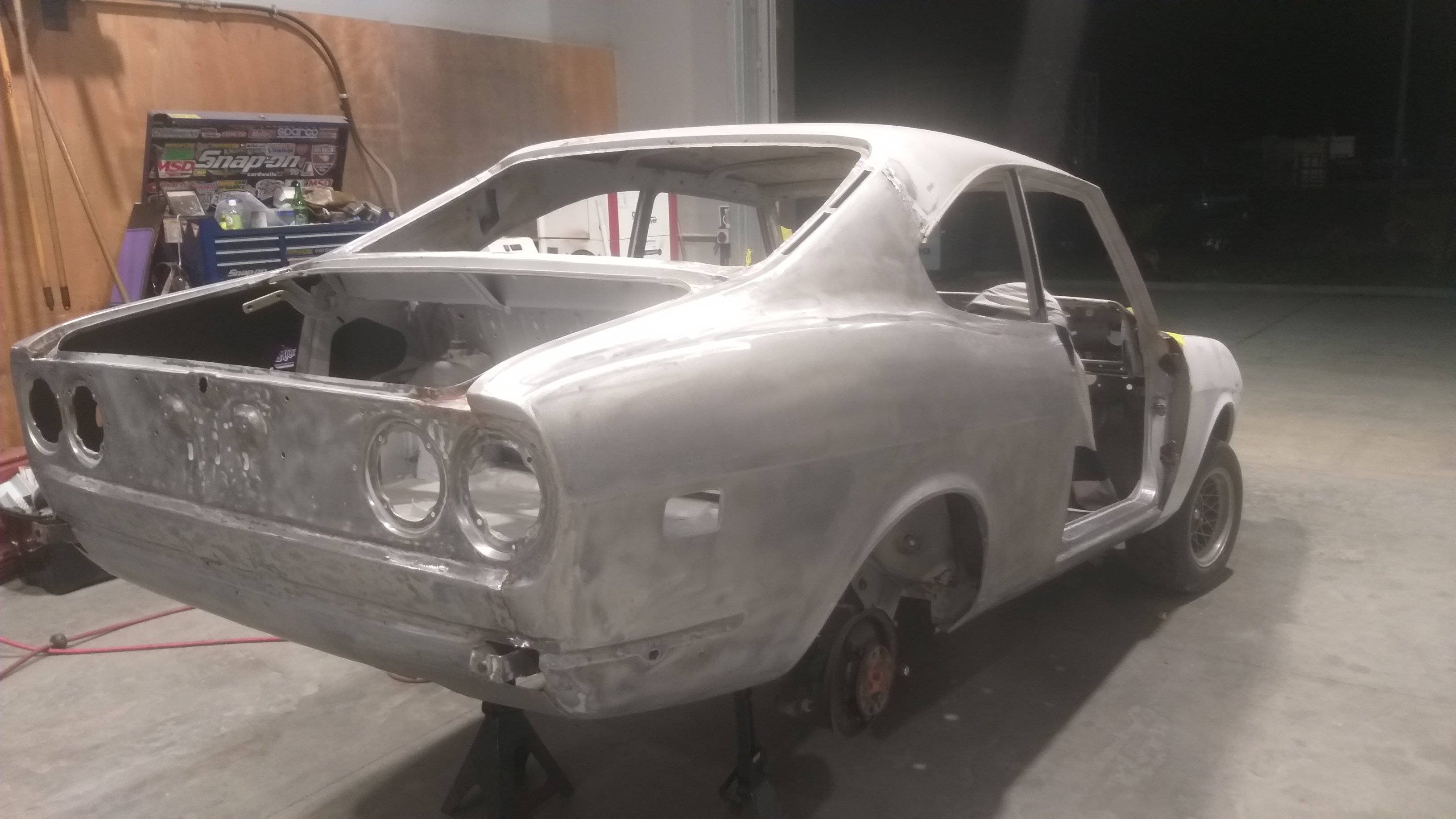
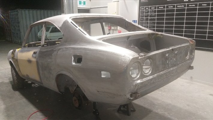
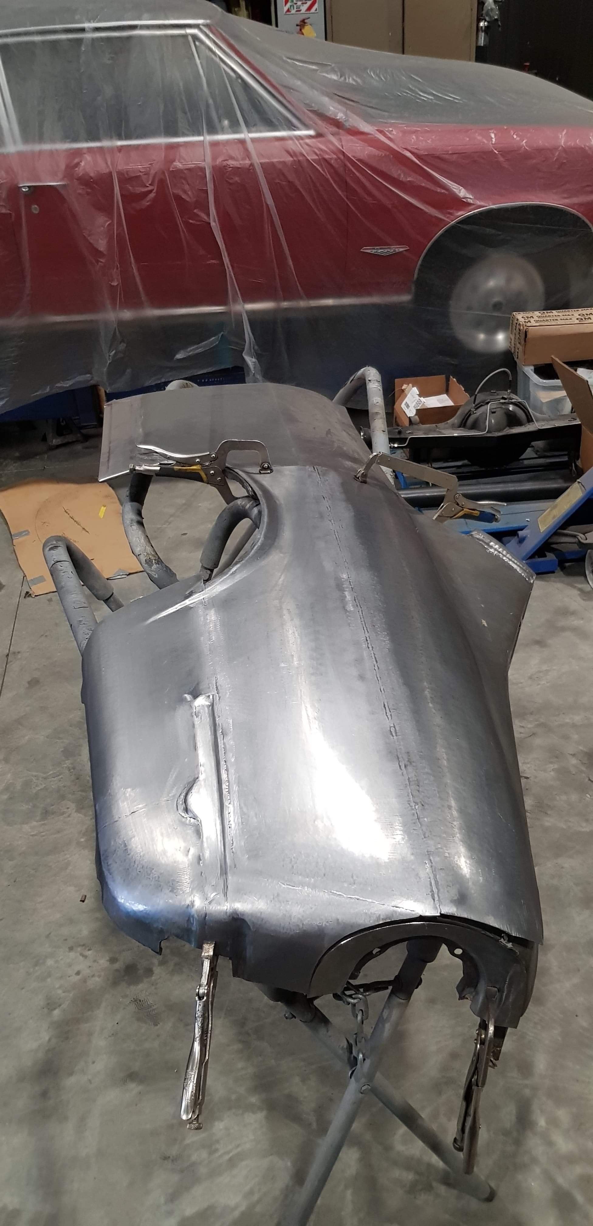
Steel work pretty much finished! Chopper has done a killer job on it, no filler in it yet, looking pretty straight in epoxy, repair certifier has had a look and is happy too!
 16 points
 -
One part I neglected to address in my previous post about the driveshaft was the sliding yoke. It was seized, and no amount of pretending it wasn't was freeing it up. The sliding yoke sits at either end of the diff half of the drive shaft. Sometimes it's on the diff end of the shaft, or in my case, it's in the middle near the center bearing, depending on where BL felt like assembling it. Either way, it's a crucial part of the driveshaft. As the rear axle travels up and down in normal driving, the rear section of the driveshaft has to raise and lower with it. The problem is that the axle travels in an arc, which means the distance from the axle to the center hanger bearing increases and decreases slightly as it moves through its travel. To account for this change in distance, the driveshaft needs to be able to change length. This is done with the sliding yoke. Inside the yoke is a series of strong splines, which mate with another set of splines attached to the end of the driveshaft. This allows the shaft to transfer power through it via the splines, but also slide in and out to account for the movement. A cap, spring and seal stop the spline from coming all the way out. My yoke didn't slide at all. It was completely compressed at its shortest length and would not budge. I tried many things to free it up, including filling it with penetrating oil and hitting it with various hammers. Nothing. I even tried hanging it and seeing if gravity would free it up (it didn't). I tried a few other things with no luck, but the one thing I was lacking was tension on the spline. Hitting it to shock it was fine, but if there was no tension pulling the two halves apart then I was only going to get so far. So I had a brainwave (it hurt). Two ratchet straps and a very sturdy workbench later, I had this contraption I ratchet strapped each end of the shaft to a leg of the bench and put tension on the shaft. With one hand I grabbed the yoke and leaned back, putting even more tension on the shaft. With my other hand, I hit the flat of the driveshaft with a hammer. Sure enough, after a few hits, I saw movement and then with a POP it fully extended. I unscrewed the cap at this point, which reveals the cork seal and washer. The cork seal is known for being pretty chewed up and is unobtainable new now. Thankfully mine was in mint condition. And for the first time I could see the splines. The old grease was black and disgusting, and the splines had obvious signs of surface corrosion. One thing to make sure of is that both halves are clearly marked so it is reassembled in the same location. I scribed lines into the yoke and driveshaft and then marked it with a white paint pen. The spline isn't keyed, so can fit many different ways. The main thing to take care of is that the UJs are in phase, which means they both have to be in line with each other. With the spline removed it was time to get cleaning. All the old grease was cleaned off with brake cleaner and a toothbrush. Which revealed why it was seized together. All the teeth had surface rust to some degree. This was binding with the internal splines in the yoke. A good wiring brushing quickly got rid of most of it, showing the splines to be in good shape otherwise. The splines were then slathered in grease ready for reassembly. The internal splines in the yoke also got a good clean Once I was satisfied with the condition of the splines I packed the yoke with grease and slid the driveshaft back in. And wound the cap back down over the seal. A quick wipe to remove the grease ejected out the breather, and we're done. The joint slides freely so should do the job nicely. With that done, the driveshaft had been completely overhauled now and is finally 100% ready to go back in the car.12 points
-
Been fucking with the router down in the cold cold shed of an evening making various things, one of which is this; I'll buy some ACM to cover it and see how that goes...10 points
-
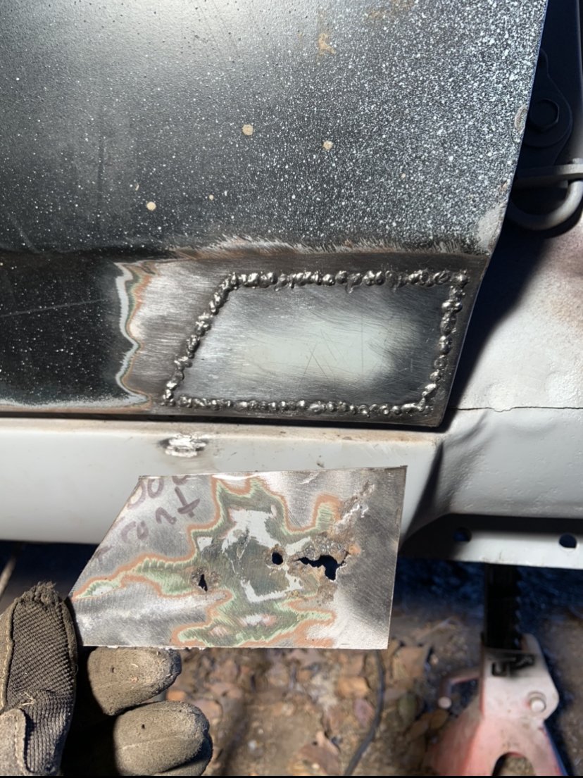
strip disc exposed the soft spots.. I need more dremel cutting wheels before attempting this one, as used last one the other day and forget to order during the day I lied, it wasn’t just the nose that rusted. for fox skates! Hate precision bonnet jobs. She’s had a wire wheel back and 2 coats of Brunox. I thought a round hole would be less likely to distort so used the step drill to open them up to fresh steel and zapped one weld at a time with a long cool down period in between. it worked, the important side is pretty flush and won’t need much aftercare. The brunox was a test, has a good name but haven’t used it before now. It’s all good, but doesn’t seem to go far and isn’t cheap. I’ve ordered some Fertan brand stuff to have a hoon on this time round, the inner of frame will be a great test for it. I got some front wheel bearings and 2L of 3M underbody Schutz for later on too. Stay tuned homos9 points
-
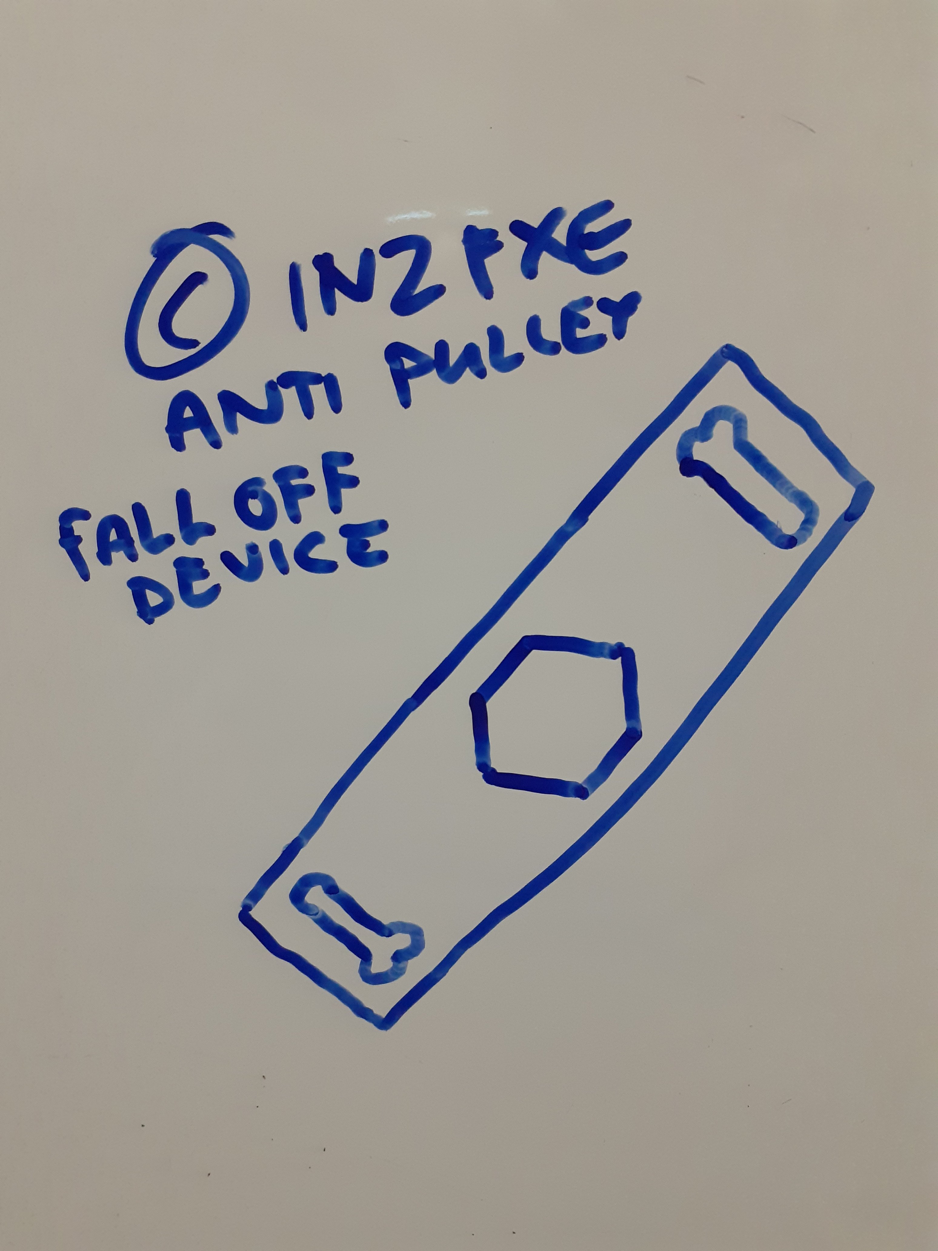
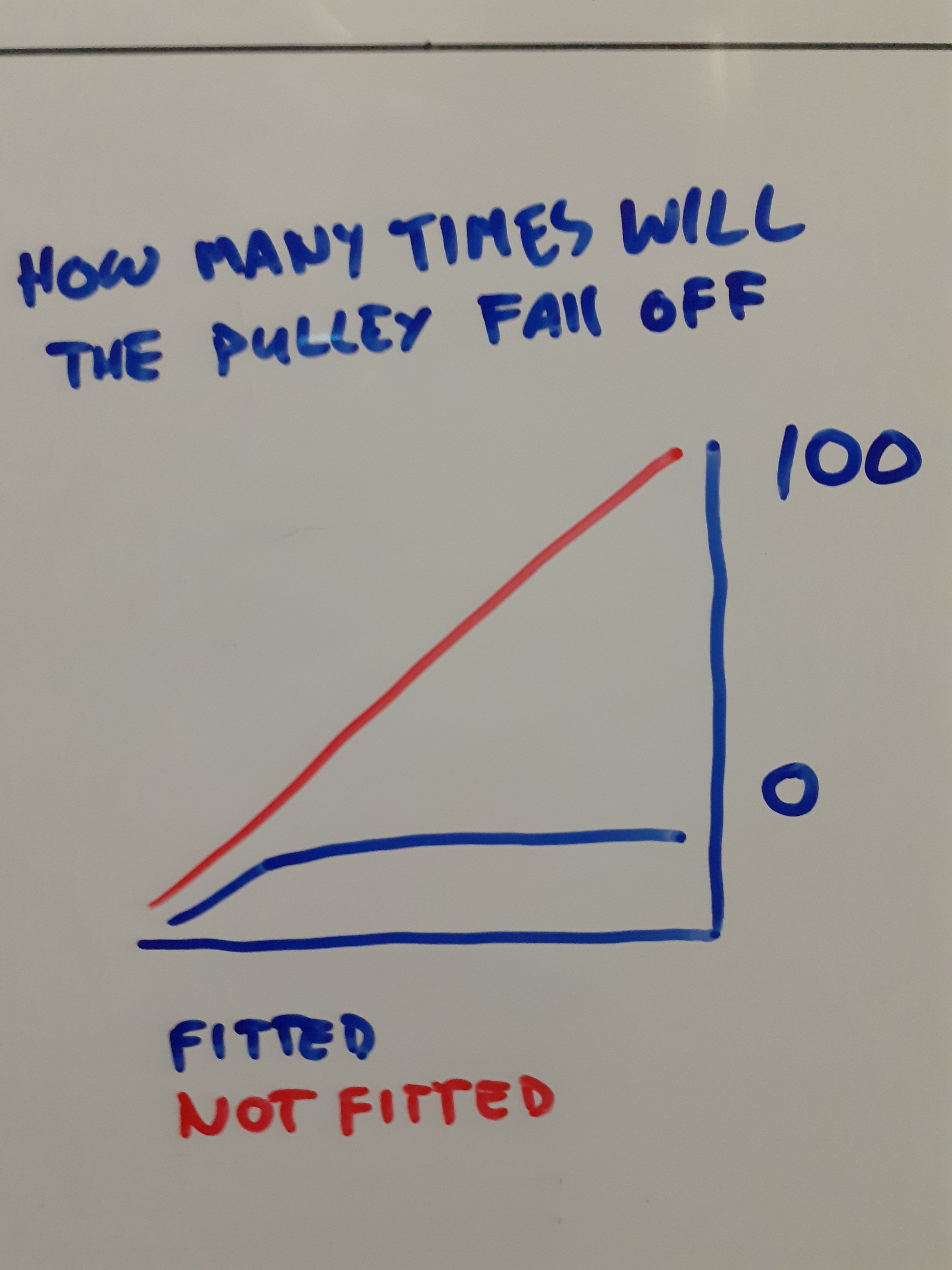
I designed a device for you that bolts on to your pulley to stop it falling off and also supplied a scientific graph as I know how much you love them
7 points
-
It's well known that dump scales read 50 kg higher on the way in than on the way out6 points
-
Time for debbie downer to pipe up. Just a request if we can put the word out about not sinking piss like it's going out of fashion to a point where you're slurring words and riding like more of a piece of shit than we already do. A few warm brion lowns/PG's throughout the day isn't what I'm talking about. But there was a certain crew that by the end of the first day - if they came near me in the pack I'd slow right down and let them pass or get way in front of them. They also came to my Raglan ride last year. I only realised how much they were drinking at the end of the day when one fella could barely string a sentence together - then proceeded to load his bike up and drive home. I've done the occasional 'jokingly mention you've had too much to drink' to these fellas but it just gets brushed off. I've spoken with a few people about the issue and it's not the OS crew that's doing this. But because we're all quite jovial and most of us are mates it's something that isn't really bought up as we're all pretty aware of this stuff already. I feel like it should be mentioned as a proper point - possibly added to the entry from? Coming from the organiser it carries more weight. Feel free to tell me to fuck off. But if I was knocked off by someone because they were pissed as a chook, fucking off would be the least I'd do to the culprit. Not trying to start a 3 page yarn about it. But just felt it needed to be mentioned.6 points
-
I took it for a trundle this morning, nothing crazy on RPM because I didnt want to stuff another pulley straight away if it was going to. But I figure while the gas level was low I'd go weigh it again at the dump. I've taken a few extra bits out, but then also changed the wheels/tyres. I'd like to get a more accurate idea of current power figure as I've only been guessing what to input into virtual dyno, based on last time I weighed it. I figured it was probably around 830kg now. However without driver, low tank of gas it's 870. Which is about same as last time, even though I've taken more stuff out and there's less gas. So these wheels and tyres must have added a bunch of weight back. Maybe the 1500 motor is a smidge heavier too. I cant remember if I was still on the factory steel wheels when I took it there the first time. But the 13" steels are massively lighter. I will do some checks to see how heavy Reflexes are to the 14" china wheels. Definitely feel a lot heavier. But semi slicks are pretty heavy too compared to a normal tyre. So that's stink news because it means with 32 litres of gas to fill it back up, it's 894kg which is way over what I need/want it to be. However the good news is this means my actual engine power figures are better than expected. Updating the weight and virtual dyno figure now shows it is somewhere closer to 135-140hp at the wheels. Which I think makes sense given it's up to 66% duty cycle on 2ZZ injectors at 55psi. So good news in the motor department but bad news overall. Because it would have been easier to keep improving the motor than it is to lose the weight needed to get the power/weight to where I would like it to be. EDIT: 13x5.5" steel wheels with 155s are ~12kg each 14x6.5" china wheels with direzzas are ~15kg each 14x6.5" Reflex with R888R are ~17kg each R888R are 8.1kg each in that size. Direzza are 7.7kg each in same size. So this means China wheels are 7.3 kg each Reflex are 8.9kg each. So can potentially ditch 6.4kg worth of wheel weight for "free" by putting R888 on my other wheels. Neither of the sets of 14" wheels are particularly light.5 points
-
I reckon a camera in there would be key to see if its engine harmonics or the belt/pulley setup harmonics causing the issue if that makes any sense. Maybe you are in need one of the most misunderstood and popular internet shit fight topics the harmonic dampener front pulley.5 points
-
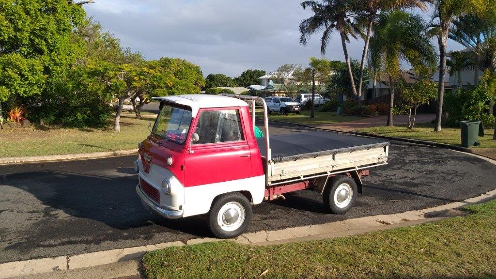
And then in other news a fellow Thames enthusiast who is visiting the area dropped by for a yarn. This sweet little truck is fitted with a V8 and associated running gear out of a Leyland P76. The cab has been converted to tilt for full engine access.
5 points
-
The whole MK.1 crew.
4 points
-
Also just to brighten the mood a little here's my fave video of the first year.4 points
-
The first year this became an issue(two rides back maybe), one came with a massive box on the back of his CT with something like 48 big sized cans of beer - they were all gone before we reached that days venue. Last year the Gyro was the booze wagon which was just as bad. Not sure if anyone remembers the start of last years ride, us all waiting to ride off from J5’s but one of that crew was skulling cans of something and wasn’t ready yet so we waited a few minutes more - all before 9am in the morning. When you’re buying cup holders for your bike to hold the beer cans and have flip face helmets specifically so it’s easier to drink and ride there is a problem.3 points
-
Thanks mate. I’m all for some shit beers thru the day, but when you’re riding 6+ hours with minimal food and water, in the hot sun your ‘normal’ Saturday’s drinking can affect you a lot. And at the end of the day we are still on public roads. Not on form to be pissed and driving thru town, so why is it different in the country.3 points
-
Why won’t the cops recover it?3 points
-
Yes! That could be relevant. The power steer ran on its own belt, so removing it didnt make a difference. But this motor never had an alternator, or any other accessories. so its got a custom bracket for an alternator only. The non hybrid motors go crank > alternator > waterpump > aircon pump. So a lot more belt wrap and belt length. The alternator bracket that @Stu made for me is nice and sturdy (thanks again) however my tensioner arrangement is really crap currently. I've just fitted a fresh pulley and bolt, lots of loctite that I'll let sit for 24+ hours. Have also hopefully done up a bit tighter than last time, with an extension bar on. If this keeps happening it might be a reason why I need to consider going to the earlier motor sooner than later. (As it will need belt for waterpump > alternator > idler)3 points
-
2 points
-
Look at that smokey little whore on the right end. The one behind Sue.2 points
-
Anyway here’s Henrae’s cock from mk1 cape
2 points
-
I do like that PGs have become the unofficial refreshment of choice for this ride They may be gross but they have everything you need for small bike endurance riding A bit of guarana for focus some sugar for energy and booze to enhance riding ability. But yes those riders take it to the extreme. We came across one of them who was confused why his bike was broken but had consumed enough codys to not realise he just needed pertol2 points
-
How many holes have you started drilling in it?2 points
-
smaller battery will probably save 10kg2 points
-
+1 to Clints method, i did this with the Impala and doing the same with the RX3. That way you can build it once how you want and not doing shit just to get it legal that your changing after costing you more money in the long run. Do it once do it right always works well. Albeit takes longer to get on the road but in the end its worth it.2 points
-
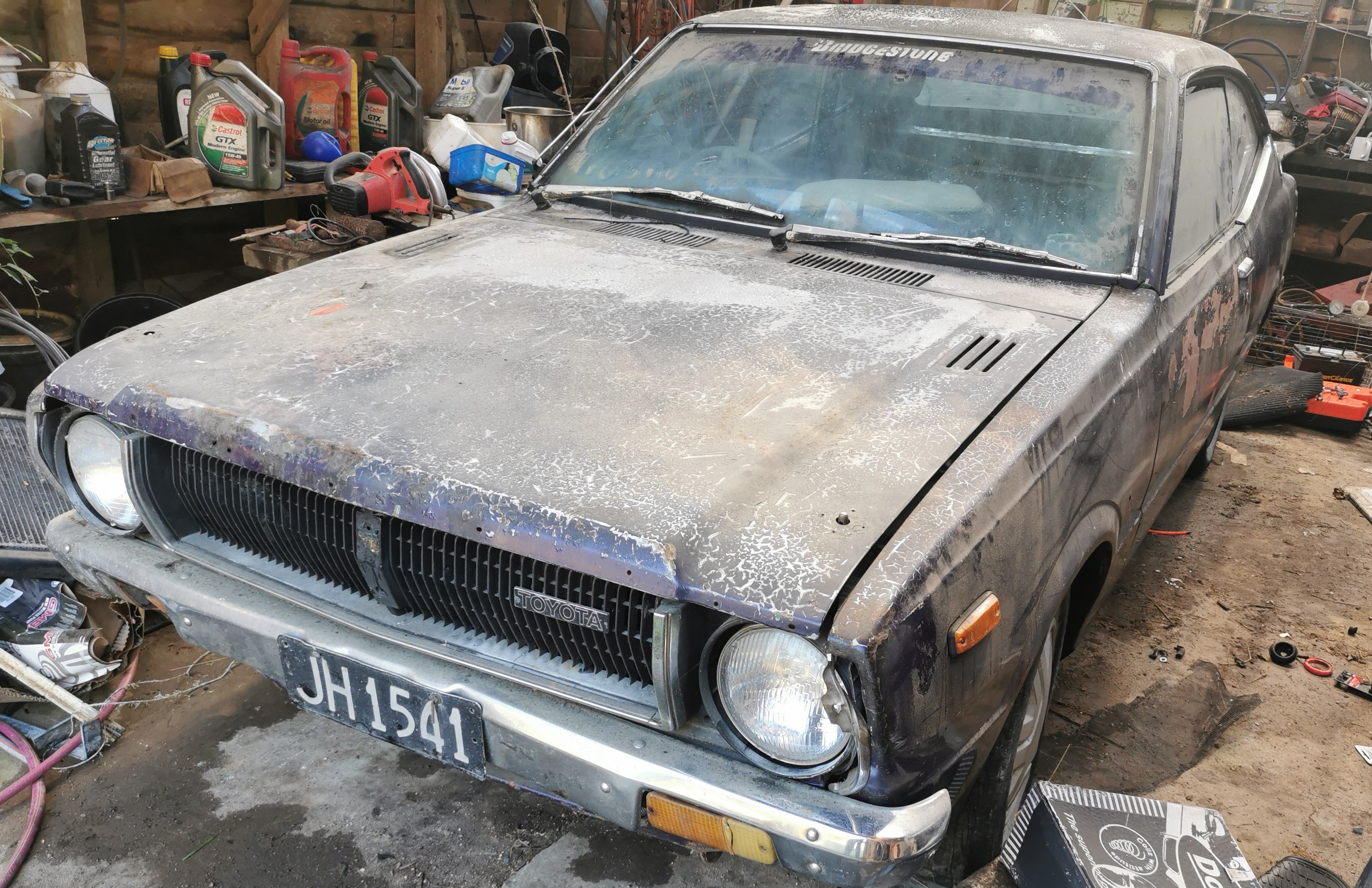
hi guys im doing a full restore of a ke35 i just picked up its missing a couple of parts i will need so if anyone has any or knows of any laying around please message me the parts are listed bellow main part is the dash panel that covers the gauges ... mine was stolen the drivers door trim that clips to top of the door beside the window and a boot lid with lock ..my lid is ok but missing the lock
2 points
-
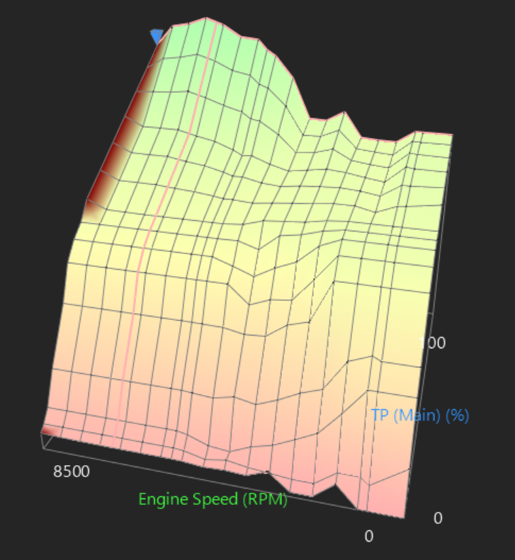
I printed some prototype long trumpets that fit under the bonnet / dont hit anything. Because I'm lazy and I figured they might not work too well. They are currently made from glow in the dark PLA haha. However, they worked a treat! Fuel table now needed around 11% more fuel at 4000-6000ish range, and then about 5% more fuel towards redline. Nowhere did it need fuel taken out. cool. So I'll remake them out of something better, maybe try a little shorter and see if I can push that big bump of gains a little higher in the rpm range. The shape of the fuel table tells a bit of a story. about 4k onwards is where it starts ramping up This is with no VVTI so once that's going I'd expect to reclaim a bunch of midrange as well, maybe a little more up top. Current problem is that it keeps spitting the front engine pulley off. It unwinds the bolt any time I rev it to the moon a few times. So maybe there's some weird harmonics going on. Tried some loctite and tightening it as tight as I could, but still happens. So will try a fresh bolt and pulley, hopefully that fixes it somehow. Maybe this motor doesnt enjoy being revved to nearly twice its intended rpm. Who can say? Also, my plan to use good tyres as a poor mans LSD hasnt worked too well. There isnt much weight over the front left so it spins it up real easy which is annoying. So will have to make a start on getting that other box sorted.
2 points
-
It's been a while since I had done any work on the Marina. The Tacho kinda progressed in the background, but most of the focus had been on getting the Carib going. But with the Carib on the road, I turned my attention to the Marina again. One of the things that had to be done before I could attempt to move the car under its own power was to rebuild the driveshaft/propshaft. I knew from when I first went under the car that the center hanger bearing was completely shot, and had collapsed, so at the very least that needed to be replaced. Ages ago (about two months ago) I slid under the car and removed the driveshaft. Hanger bearing was looking a bit sad I'm glad I took it out and checked, it turns out the bolt that secures the two halves together was... missing. There was also play in at least one of the universal joints, and it wasn't the one secured by clips. Two of the three UJs are secured by a process called Staking, where they physically deform the metal around the edge of the cap to hold it in place. This is a real pain because it needs some skill and usually a bigger press than I have to replace them. You can see better detail in this example image A normal universal joint is secured by a big circlip in a groove, which is far easier to work with. This prompted me to reach out to a fellow Marina owner and purchase a spare driveshaft off him, which although had a failed center bearing too, used Circlip style UJs and had the securing bolt for the two halves. I finally got around to attacking the replacement driveshaft the other day. I wanted to refurbish the whole thing since it was old and I didn't want to have to pull it out later to replace the UJs. There is a great video by Chris Fix on how to replace UJs. He makes it look easy, but I hated this job. First I cleaned it up a bit, marked the alignment and removed the clips with a pair of circlip pliers This end was pretty straightforward. Big socket (24mm impact) underneath, and a smaller one that fits into the recess (14mm impact, 16mm normal) on top and using a big hammer, smash the 14mm socket down, pushing the UJ cap out the bottom. It came apart more or less with no trouble. Push the joint down, pull the cap out. push the joint back up, pull the cap out. Done. To fit the new joint, I found it best to lubricate the recess you are pressing the caps into with clean ATF, and then press them both in together using a bench vice. This helps to press them in square. I didn't do this for the first couple, I used the method of hammering the new caps into place. I did unfortunately find out why they recommend sealed joints without grease fittings... There is not enough room in the joint for the long grease fitting, and you would risk breaking the fitting off when the joint moves. These joints were very cheap on clearance though, so I persisted anyway and dealt with that later. One end of the driveshaft done. The new joint is smooth and feels great. A few pumps of the grease gun and it was ready for action. Kinda. The next joint was well jammed in place, to the point it blew the end out of the cap before dislodging it You can tell from the state of it when it did come out that had some issues. Being a sealed unit, you can't grease it, so once the grease hardened it was all bad. Fitting the replacement wasn't much better. This was when I was still using hammers to fit the caps and I came really stuck on this second UJ. I can only presume the caps weren't going in quite square, which meant they were binding. After a few tries I moved to the press, which only did one thing, it blew the new cap to bits. But it also scored the cross piece So no, I'm not perfect, I do sometimes make stupid mistakes too. I took a little break from that UJ here as I needed another new one to continue and moved to the hanger bearing. I tore the rest of the outer part off and used a hammer and pry bar to carefully drive the old bearing off. After a little bit it popped off With the bearing off it was easier to handle, so had a go at replacing this UJ. This was the only one that is greasable, and as I later found out this is because there is a small recess in the flange to allow space for the grease nipple. You can just make the recess out here. This was another one that I was having a battle with, but instead of trying to use more force to press it out, I just grabbed the grinder and used a cutoff wheel to make quick work of it. Take that! The new caps pressed in fine, using my newly honed method of starting with the flange, and pressing the caps in with my vice until they are flush, and then tapping them in the rest of the way with a socket and hammer until the clips fit in the recess. A couple of taps on the flange frees the joint up. Another rookie failure here, I didn't notice there was a recess for the grease nipple at the time, so fitted the joint in the wrong orientation. Argh. Without another new joint to replace the damaged one, the only thing I could do was fit the new center bearing. This was as easy as popping it into place, with the longer side facing the splines and then tapping it down until it bottoms out. I used a big socket and an old bearing race as a spacer. I had a new joint arrive a couple of days later, so in that went. I initially tried fitting it to the existing flange, but it didn't feel right, so went with my gut feeling and pulled the flange off my original driveshaft, and used that instead (thankfully it was the one joint that wasn't staked). It's not ideal, but I feel like the flange may be damaged on the other one which is why I was having so much trouble. The joints pressed in with no issue. Ignore the placeholder bolt, that was just testing it was a 6mm grease fitting thread. The other two joints were 1/4" UNF thread. Speaking of, to sort my issue of all the grease nipple being too long and fouling the joints, I went out and bought some short grease nipples. These clear with ample space, but were an utter bastard to fit. They have a bigger hex than the longer ones, and there is no room to actually get anything on the hex when you screw it into the joint. I ended up tightening them up one flat at a time with the spanner sticking straight up in line with the fitting. In hindsight, I would get the sealed joints, but if I couldn't, I would get some grub screws with the correct threads and use them to plug the holes after greasing. Either way, the joints are all greased, and the holes plugged. With all the joints replaced and the new center bearing in place all I had to do now was refit the two halves of the shaft. The spline is keyed with a double width tooth, so it can only fit in one orientation. Take note before sliding the spline completely down that it's easier to start fitting the bolt in the center when the shaft is slightly apart as there is limited space with the joint in place. I did the bolt up as tight as possible, and then bent the locking tab over. Now all I need to do is fit it back to the car, but that can happen another day since I can't be bothered rolling around on the ground right now. Once that's in, since the clutch is bled and working, all that's left is new tyres, which are currently in a stack next to the car waiting for me to strip the old tyres off and paint the wheels. Getting real close to moving under its own power for the first time in about 25 years.2 points
-
It feels like it's been a huge uphill battle getting a working tacho in this car, but I think I have finally mastered it. Over the past few months, I have somehow ended up with a few different clusters, including two with the elusive tachometer module, and the one with the non-functioning clock I previously made a post about. The first three dial with tacho I bought from Trademe. It was the correct Aus cluster, with the lower 5500RPM redline, and a couple of other small differences as I would later find out. Eager to get the tacho in and working I started to dig around the wiring diagrams to work out what I needed to do. I had heard rumours that the wiring was already in the dash, behind the cluster, and sure enough, after some poking around, I noticed a white wire tucked away with a joiner in the middle of it. This tracked with what I was expecting to find based on the wiring diagrams. It was a big loop in the harness. I fished it out from behind the duct and unplugged it. A couple of quick checks and I was sure it was the coil trigger for the tacho. On the cars without tachos, this is just looped in the dash but needs to be connected or it cuts power to the coil. I guess it made it cheaper and easier, to just use the one harness. The back of the tacho unit has corresponding bullet terminals So I plugged it into the dash, and bam, nothing happened. Well, the alt/oil lights worked as they should, but the tacho was dead. I was a bit miffed Nothing more to do then but to get to disassembly and find out what's wrong. The tacho unit is held into its housing by a couple of screws through the back, and the fascia/glass in the front. This is what the module looks like removed. Having already googled "why does my Smiths RVI tacho not work" I could already see something was wrong. Those four holes in the foreground, under that red wire? Yeah, according to google there should be a transistor there, and it's crucial to the operation of the unit. The solder pads had clearly been messed with too. It looked like someone had desoldered the component with a blowtorch. I hit the seller up and asked if he knew why it's been molested, and he just pleaded ignorance and fobbed me off with a "oh well, it's an old part". I suspect the capacitor or transistor had failed at some point (which is common) and someone tried to fix it. Failing to have the right parts on hand or something, they just chucked it back together and set it aside. As fate would have it, a fellow classic car sufferer on a forum I'm on knew I'm suffering the Marina affliction and mentioned that he had come across some Marina bits as part of a garage clearout, and would I be interested in a cluster he found? Heck yeah I would! The legend donated this to the cause, so a huge Thank You. So, this was the second tacho cluster I have. It came in a tidy surround, but it was brown, not black. No issue, They are easy to swap, and I only really needed the guts. Differences to observe. The silver rings around the dials, instead of the black the Aus cars have, the 6000RPM redline on the tacho face (ignore the askew tacho, I had already started to disassemble it), and the different markings on the fuel and temp scales (0 instead of E, and adding the N to temp). One final difference I didn't notice initially, is the warning lights are different, with some either doing different functions, or in the case of the indicator telltale lamps, not there at all. The UK cars seem to use one single green light to show the indicator is on, whilst the Aus cars use the two spaces above the center dial as left and right signals. *removes anorak* Right, so this cluster. Excitedly I plugged it into the car, and we had some success. The tacho moved! But it barely exceeded 1000rpm when revving the engine. I think this one may have been suffering from the known issues Smiths RVI tachos suffer from (bad capacitors), but instead of messing around with the old inductive RVI style guts, I spent a hefty whack of cash on the Spiyda RVI-RVC conversion board. The original RVI tacho is current sensing, so it intercepts the power feed to the ignition coil, and by some wizardry senses the pulses and creates a signal for the tacho to output. The issue with this is apparently the tacho only works with points, and in the future I want the option of upgrading to electronic ignition without having to replace the tacho again, so it had to go. The Spiyda board removes all the existing guts from the tacho, and replaces it with a new board that reads the signal from the negative terminal on the coil (like 90% of tachometers). Heck, it can even be fed a signal from an ECU. It's pretty swish stuff. I stripped the second tacho out of the housing, and you can see the missing component of tacho one here; the silver can is a special transistor. I started with the guts of the first tacho since that one was dead in the water anyway. Spiyda has extensive instructions on its site, here, so follow those, but this is how I went about it. The first step is to remove the needle. You don't need to mark where the needle sits, just make sure the mechanism is against its stop when you refit the needle. To remove it I used an old business card with a notch cut in it, and a sturdy fork. The business card is to reduce the risk of damage to the face. A swift lever upwards popped the needle off. Two little screws secure the face. The kit comes with a tiny screwdriver to remove these. Now cut the power feed wire, and the two thin wires to the mechanism and remove the two screws holding the circuit to the frame. It should pull off the front. The new board then gets screwed in place Now solder the wires in their respective places (in my case the black and red wires had to be swapped). and you're ready for testing and calibrating. Now, I did make a mistake in the above photo. It turns out that the video I was following, made by Spiyda, was out of date, so you no longer calibrate the unit by putting the red clip onto the tacho feed (which I made from the old RVI tacho feed, by cutting a section off and soldering it to the board). Instead, you need to clip the red clip to the solder pad on the far right, closest to the big chip (on the other side of the board), or solder pad number 4. With 12v connected to the spade terminal on the back, the red clip on the solder pad and the black clip on the metal frame, it's time to calibrate. Now, this was a real ballache for me. In the end, I don't know why it suddenly started to work properly, or what I did differently, but it was chaos. The instruction and files to download for calibration are on the Spiyda site, here. Basically, you play a square wave audio file at a certain frequency through the cable at full volume. That frequency should correspond with a certain RPM reading on the tacho. Since I was using a low revving 4 cylinder engine, I used the 100 and 200hz files as this should read 3000rpm and 6000rpm on the tacho. I had various levels of success depending on what device I was using. My Macbook, no good. My phone, initially average. My windows based Dell tablet, good but with some issues. I could get it to read 3000rpm, but doubling the frequency would either make the needle drop or only increase by a small amount. There was also a big jump in the needle at the start and it kinda crept down. This Gif shows the issue I was having. This is the 100-200 sweep, where it starts at 100hz and then shifts to 200hz. You can see the 100hz once the needle settles down, but then when it changes to 200hz the needle drops to just under 2500RPM. I had been in contact with Spiyda support for a while, since even before calibration issues I had issues getting the unit to respond in the first place, and they had been very helpful in getting to where I was, with prompt replies, but then the support suddenly went cold and I heard nothing further from them. It even got to the point of stripping down the second tacho and seeing if the issues were limited to the first one; they weren't. I persisted with various things, and eventually I had great success using my phone. I don't know what changed, or why it worked now but didn't earlier, but suddenly I had 3000RPM at 100hz and 6000RPM at 200hz. It needed a small tweak of the calibration pot on the back, but it was rock solid. With much excitement, I rushed to the garage and reassembled it into its housing. And with a temporary wire run outside the car from the coil negative to the cluster, I fired the engine up. Nothing. *Sigh* And then I remembered there were options for the input. There was a high voltage and low voltage signal option. In hindsight, if I had paid attention initially I wouldn't have wired the input to the high voltage "sports coil" option, and should've used the "normal coil" option. Oops. It was easy to fix once I removed the guts from the cluster and moved the white wire one pad to the right. I reassembled the cluster and plugged it in. Success! I've run the car a couple of times since, and the tacho seems to be fairly accurate. It doesn't need to be 100% accurate, just within the ballpark is good enough, and better than Leyland would've done. It responds quickly and is very stable. I still need to run the tacho wire inside the car, but that's easy enough to do. I should probably fit the surround back on the gauges too since they are more or less done now.2 points
-
Best 'mod' so far.
2 points
-
Help I am a new to the site. Dose anyone know anybody can rebuild a vacuum advance in Auckland? or anywhere in NZ? Quality rebuild no longer in business.... Many thanks! Its for a Honda City turbo 2...1 point
-
How good man! I saw Choppers post yesterday on insta, looks so sweet.1 point
-
So stoked to see this coming together!1 point
-
Shit thats looking good man! You must be stoked. good progress forward1 point
-
I would recommend against that one (althought it was my first thought too). I doubled the RPM of my TF125 and it started vibrating the exhaust bolts out. I lock-wired them, but then they still loosened just a fraction, and everything chatters without being able to come all the way off which totally fucks all the threads and mounting faces. Cletus patented locking device looks like a very good solution though.1 point
-
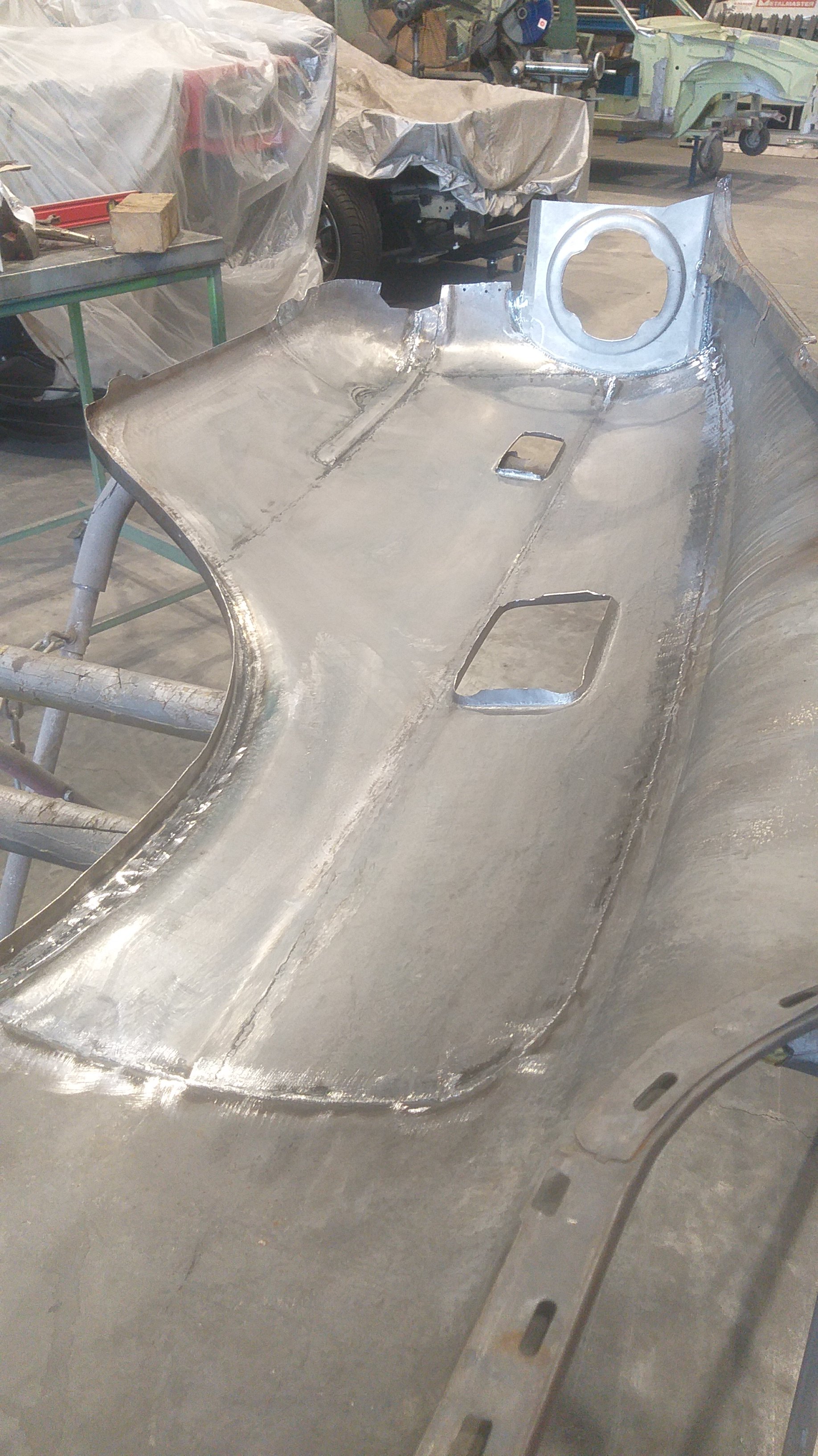
Have you considered acid dipping panels like the bonnet that is split apart? Personally I found this a cost and time effective process, and can be 100% sure that you have found and killed all the hidden rust/pinholes etc.1 point
-
Found an alloyhead, c2 casting so a bit small on the chamber size but will cc it first and doublecheck. Pics once i collect.1 point
-
Possibly relevant1 point
-
BZZZZZZT BZZZZZT goes the welder1 point
-
/or just drill and lock wire the bolt to one of the threaded holes /a big nordloc washer It must be getting some really good harmonic wiggles to make that come loose1 point
-
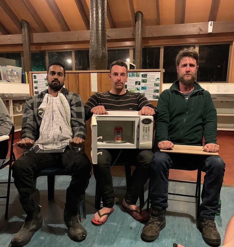
Upon the walls of the waikaremoana mess hall I stumbled across a rare pic of The Hokianga Halfwits 3rd XV, colorised from 1917. Due to the war effort the team was reduced to three players that season. As opposed to defaulting, the men played each game with a 3 man side and amassed a world record point differential of -14,000 after 6 games. from left to right; Kamahl, Tom Selleck, and the villain from Lethal Weapon 2. insert: the microwave from the Rawene Tea Rooms which served a whopping 400 roast dinners during the winter of 81.
1 point
-
@Chunky_tmentioned this... I meet the pre-requisites (other than riding ability). Maybe I just commit...what day do you reckon you'll leave from Palmy? There is a part of me that would love to ride from Nelson and ignore the dirty looks when I request unpaid leave...1 point
-
Who's going to join the 250 gang? We'll be starting from Palmy on XRs and DRZs and heading up to Whak via Napier and Waikaremoana. Here's my whip for this year:
1 point
-
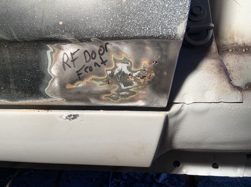
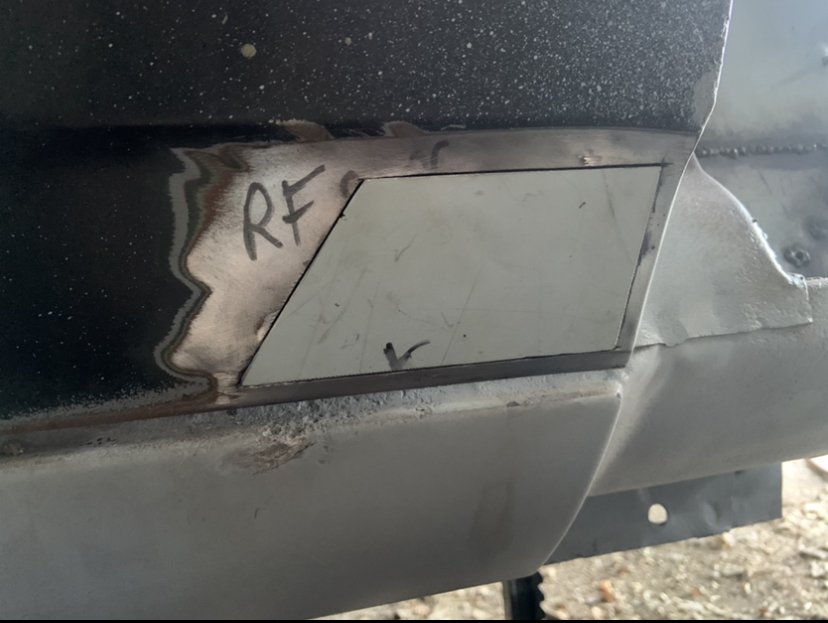
Well that was never going to fix itself was it.. rust bomb with a lit fuse! Remember I said I spent ages with air and vacuum yesterday getting scale out? Missed a bit.. Thankfully the skin is 95% mint, it’s just the very front ‘nose’ section that’s let go. Plenty of hours in the frame though. I’ll clean it up and rust kill it and paint it then put the skin back on before I repair it so it doesn’t get out of shape.1 point
-
1 point
-
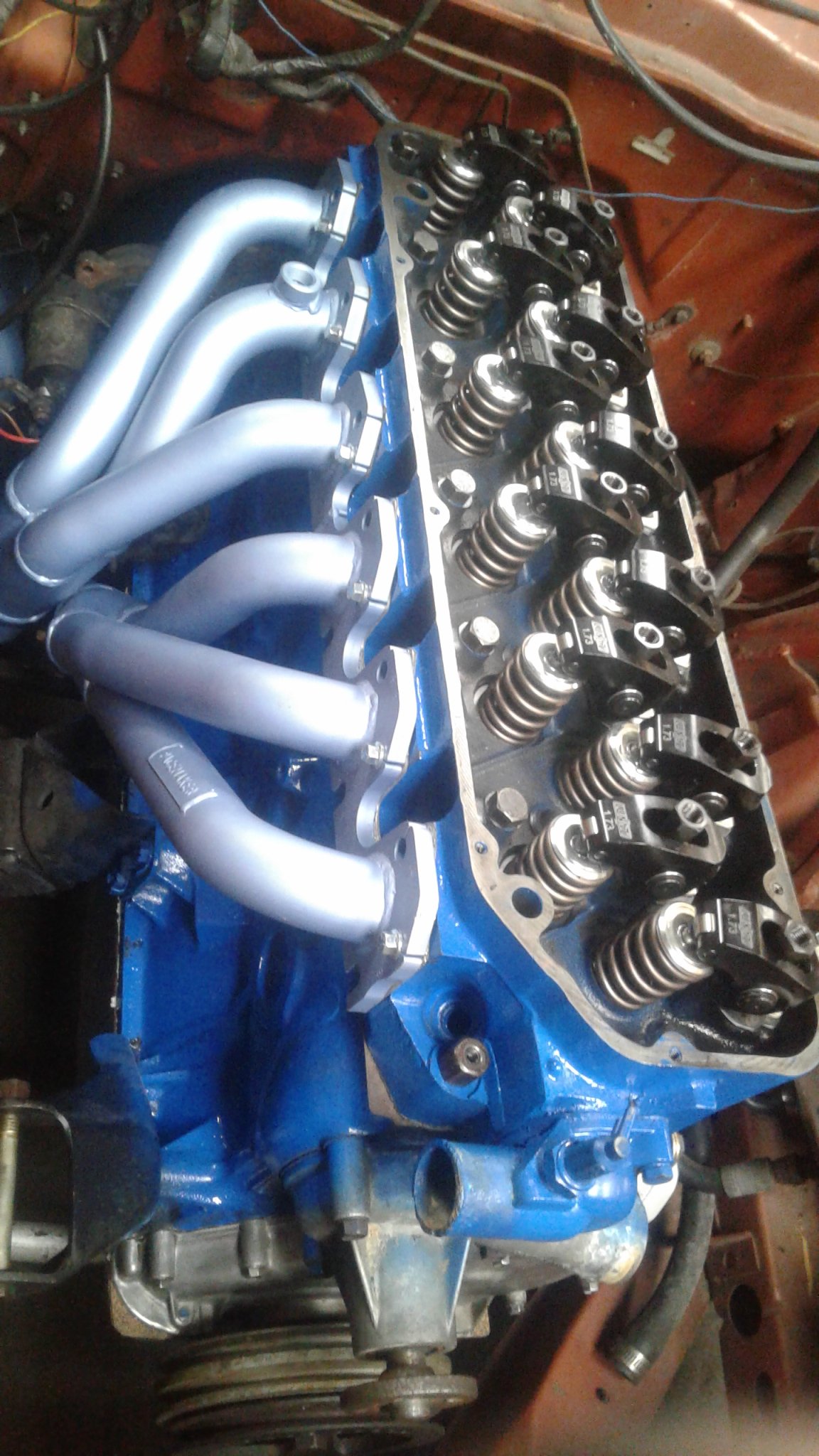
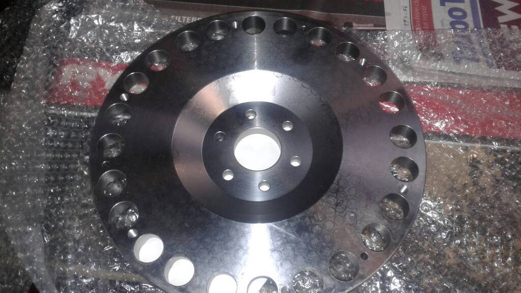
Roughly xmas 2016 the motor came out again. I had managed to find a 4speed, so in the interests of going more sporty than cruisy, the old 6 was getting more go fast bits. Bigger bumpstick, again from kelfords. CAM LIFT: in 0.325 ex 0.327 NETT VALVE LIFT:in .553 ex .556 ADVERTISED d : in 274 ex 286 DURATION : in 230 ; ex 236 Over .5 inch of lift with these motors and the steel rockers tend to bind up, so an order to summit got me some roller rockers, studs and guide plates. Tracked down a company in hawkes bay who do billet flywheels for speedway 4.0l motors. Score. Fitted ring gear from an xe and drilled the mounting bolts out to 7/16, and it was good to go. 6.5kg instead of 13kg.
1 point
-
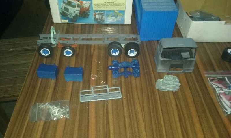
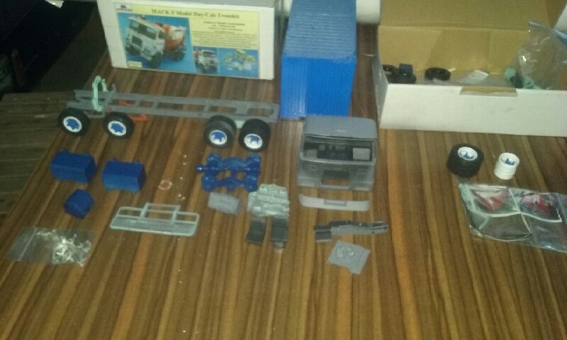
Ooh, 1/24.... Forgot abut this one, found in a box of cassette tapes at my Dads the other day. Pretty cool & rare kit, may give it a bit of a refresh for old times sake. Anyway, hopefully going to get started on the Caddy tonight.1 point
-
1 point
-
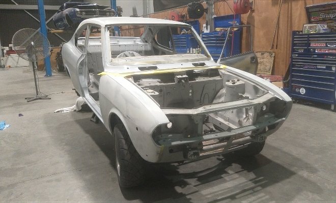
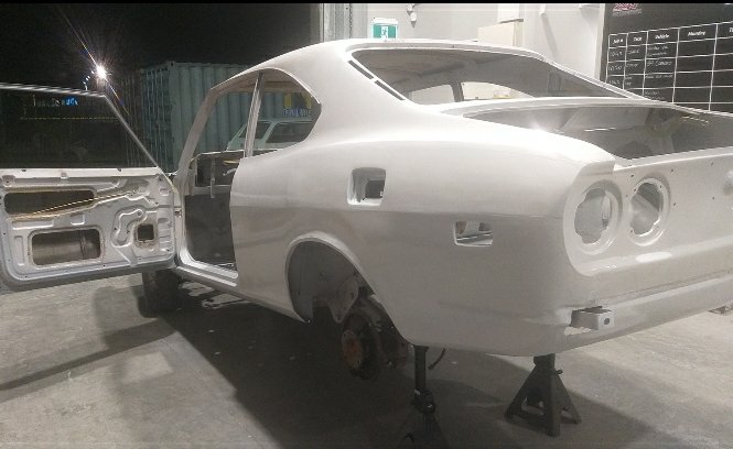
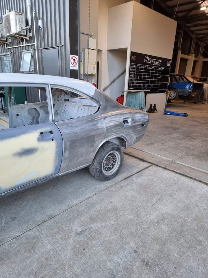
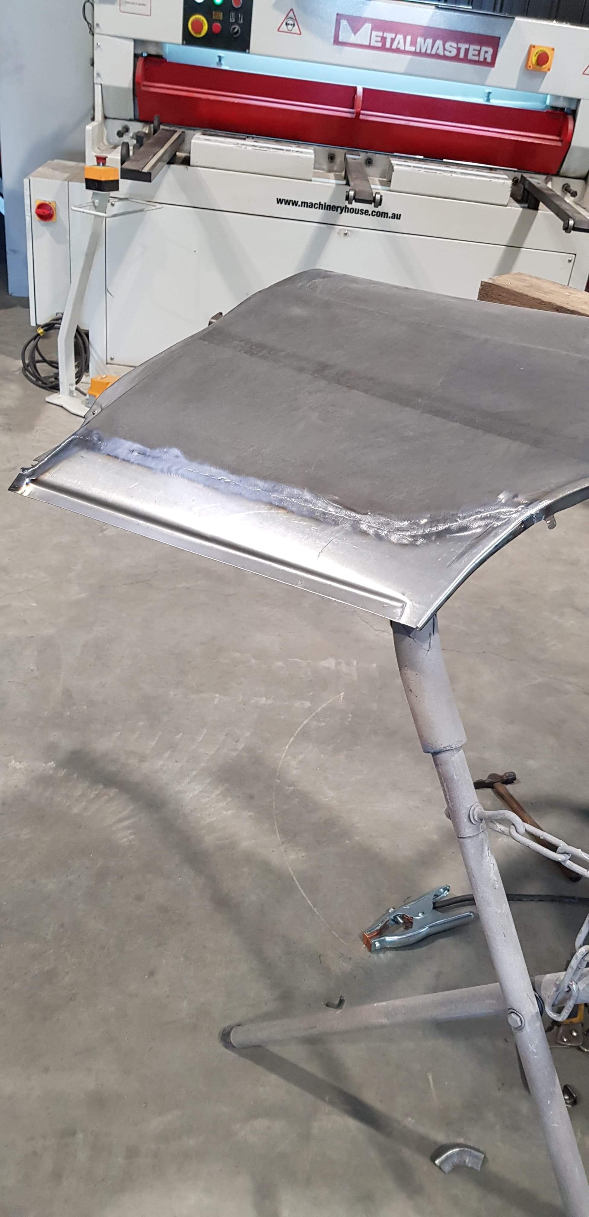
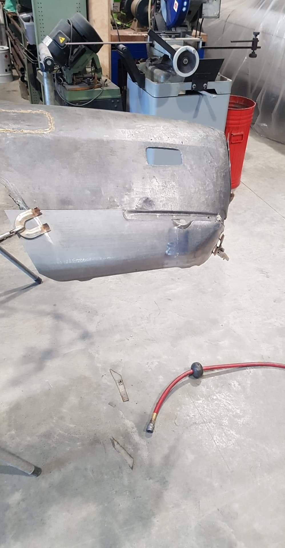
Choppers halfway through fab on the 1/4, shaping up nicely tho. Also scored a rare asf NOS front guard! *pics out of order
1 point
-
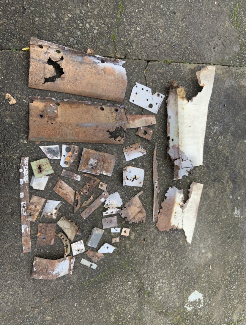
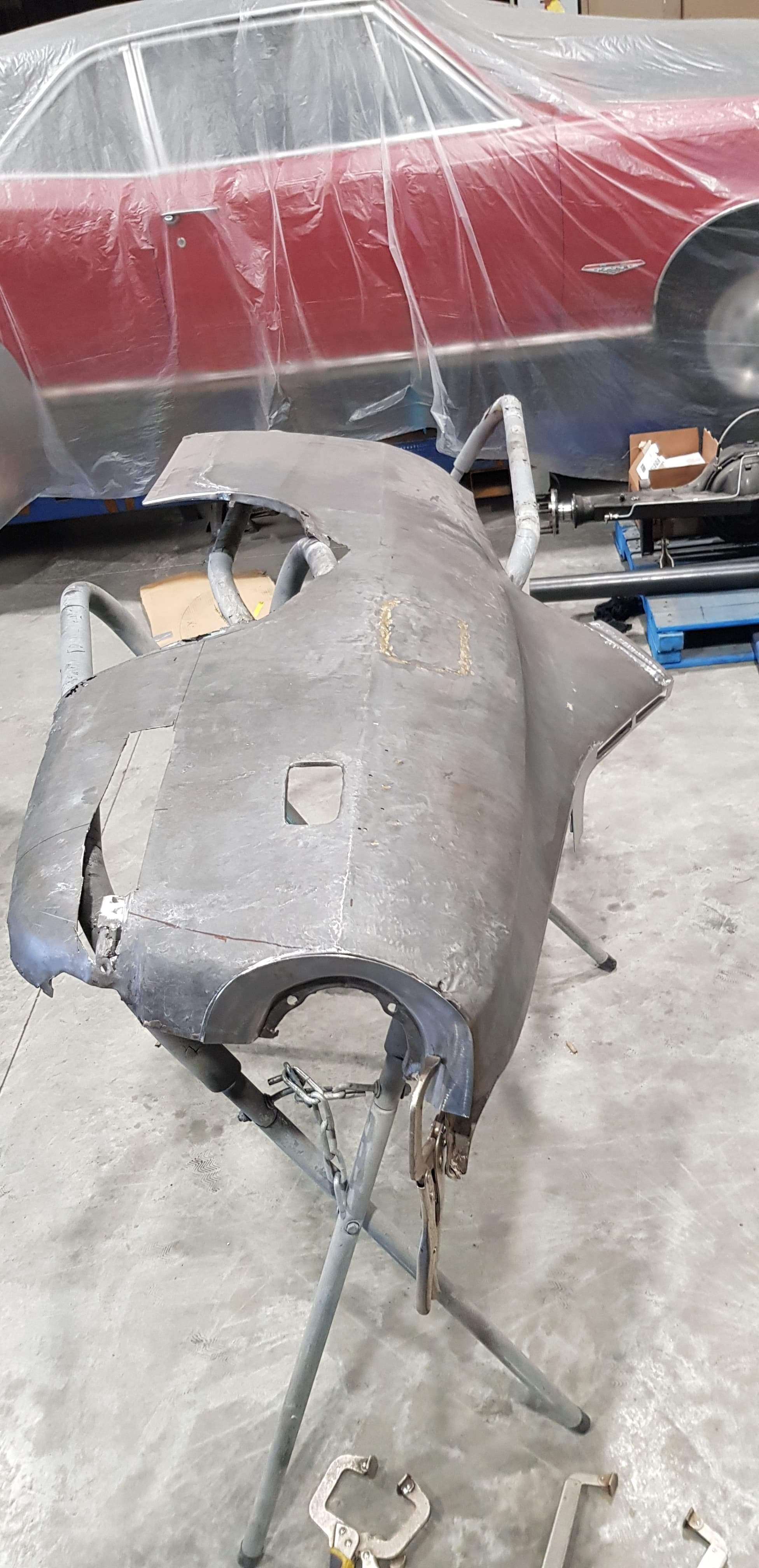
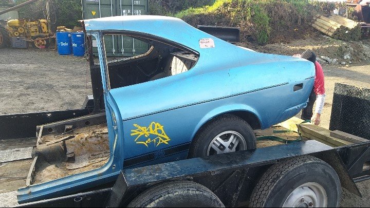
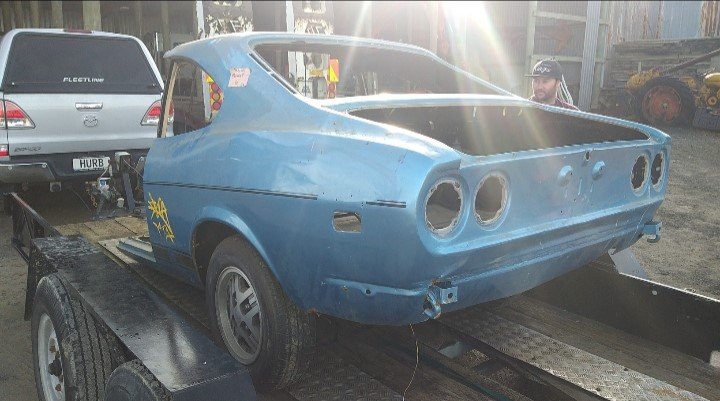
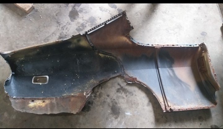
Tried to find a new 1/4, found a NOS one, but by the time it got to me it was nearly $5k! - pass. otherwise options are very limited for these coupes now Have ended up taking the 1/4 off this half cut a mate had stashed (ill weld my shitty one back on the half cut), once removed it had plenty of Mexican repairs, it wasn't great, but still better than what I had, Choppers Auto Body says hes far happier repairing this so its currently at the dippers awaiting a full strip.
1 point


This leaderboard is set to Auckland/GMT+12:00