
Leaderboard


Popular Content
Showing content with the highest reputation on 03/08/24 in all areas
-
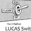
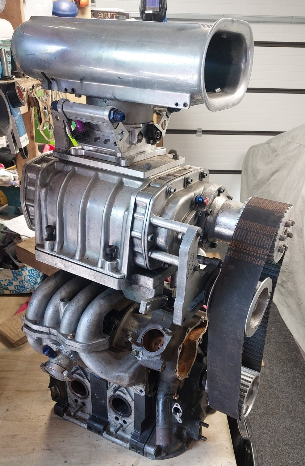
Sold the ROTECH BP, but before I whip it out, have dummy mounted the blower to check cut lines for the bonnet, so I can put a massive hole in it. 40 vs 30 tooth (1to 1) pulley, Unfortunately I'll have to run the under driven pulley to get it through cert which is only 7-8 psi. The small pulley will be double that, but intake temps will skyrocket, and I won't have enough money to get car legal as well as work on cooling. Water meth will be on the cards, as is maybe Water to air intercooler. I'll just focus on redesigning the intake, building a fresh new block, setting up EFI and a host of other items before I worry about decent power. Also that scoop won't pass, so I need to find a low profile solution for air filtration into the Xtreme rotaries 1200cfm 8 injector throttle body., I'll only need to run 4x 1000cc injectors for what I'm doing
 17 points
 -
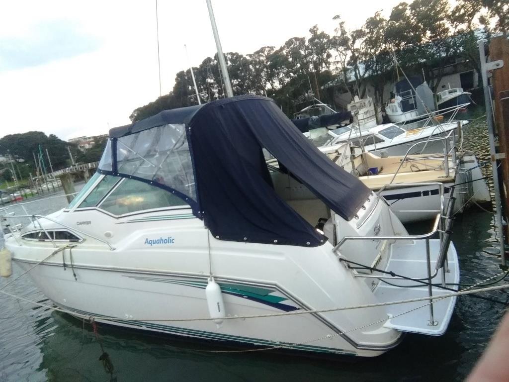
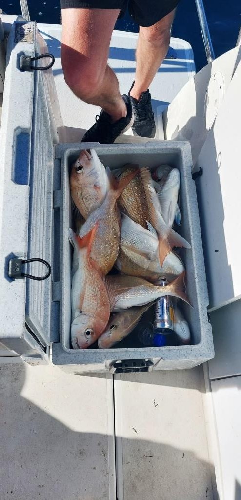
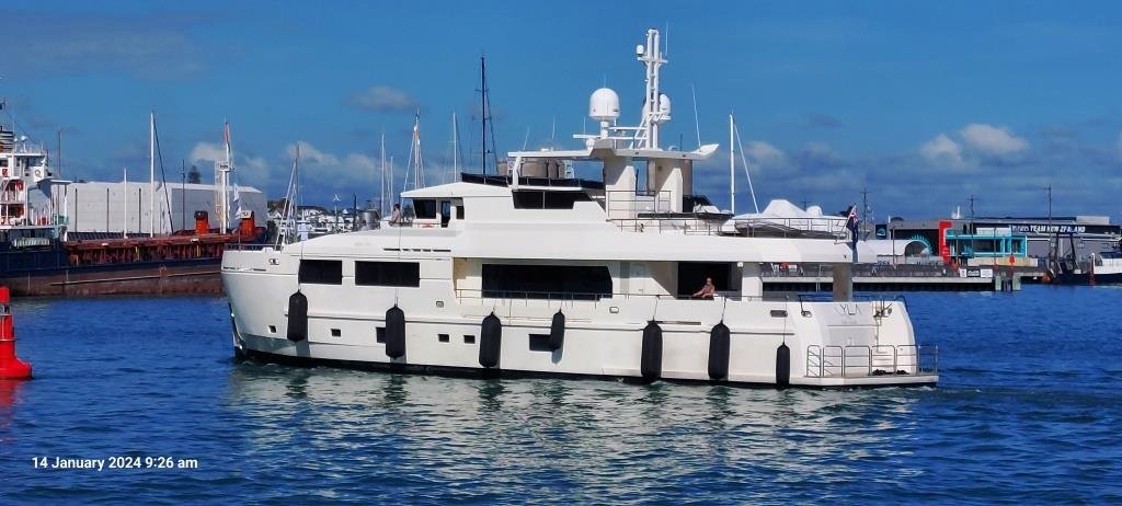
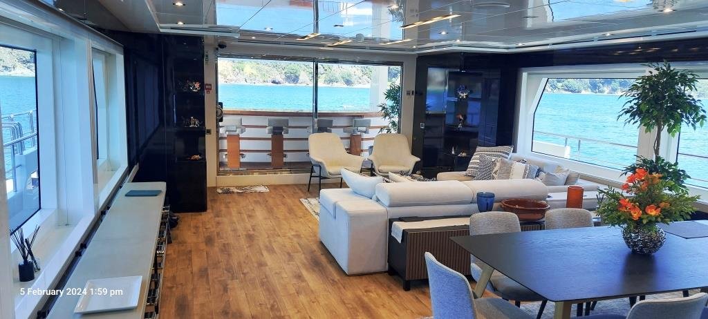
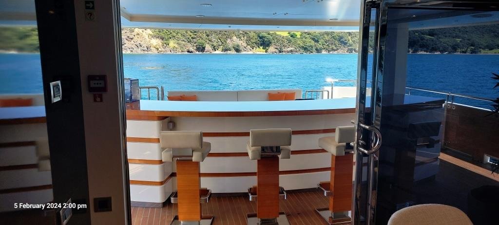
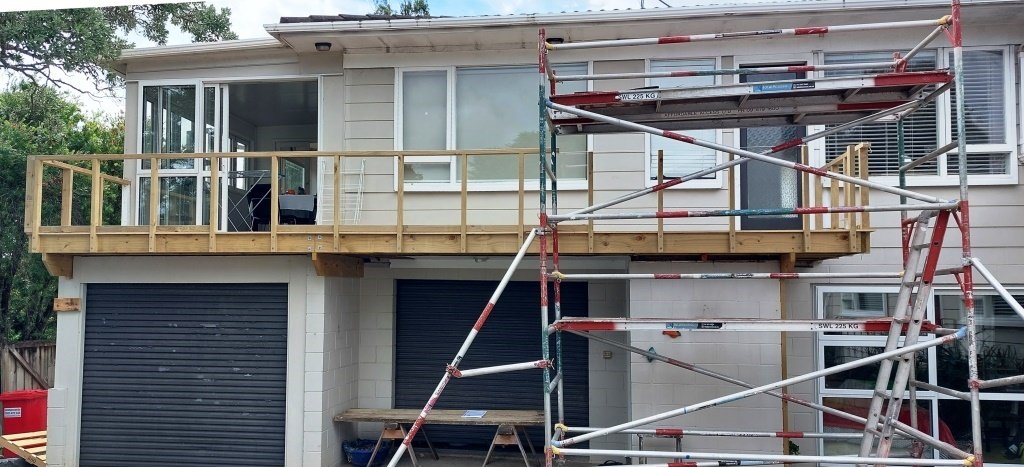
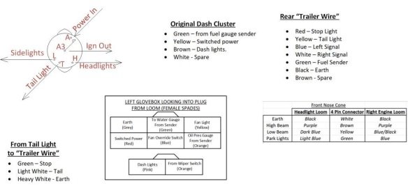
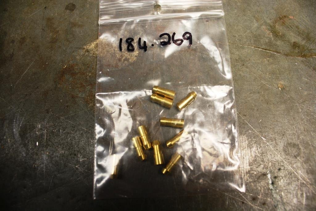
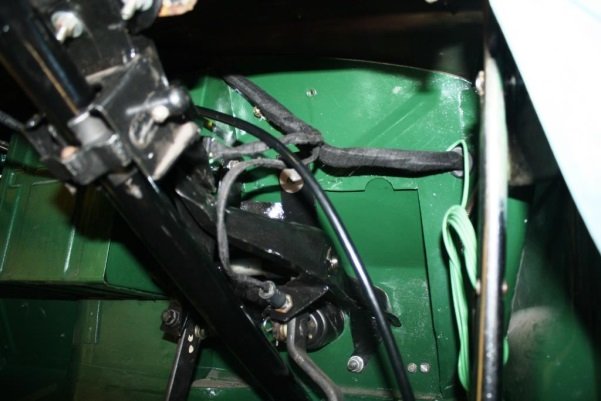
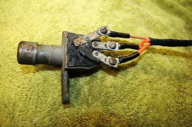
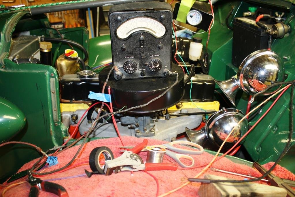
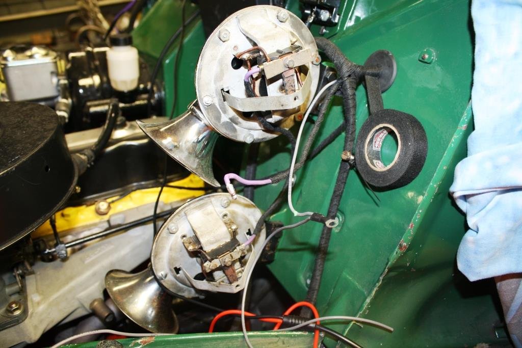
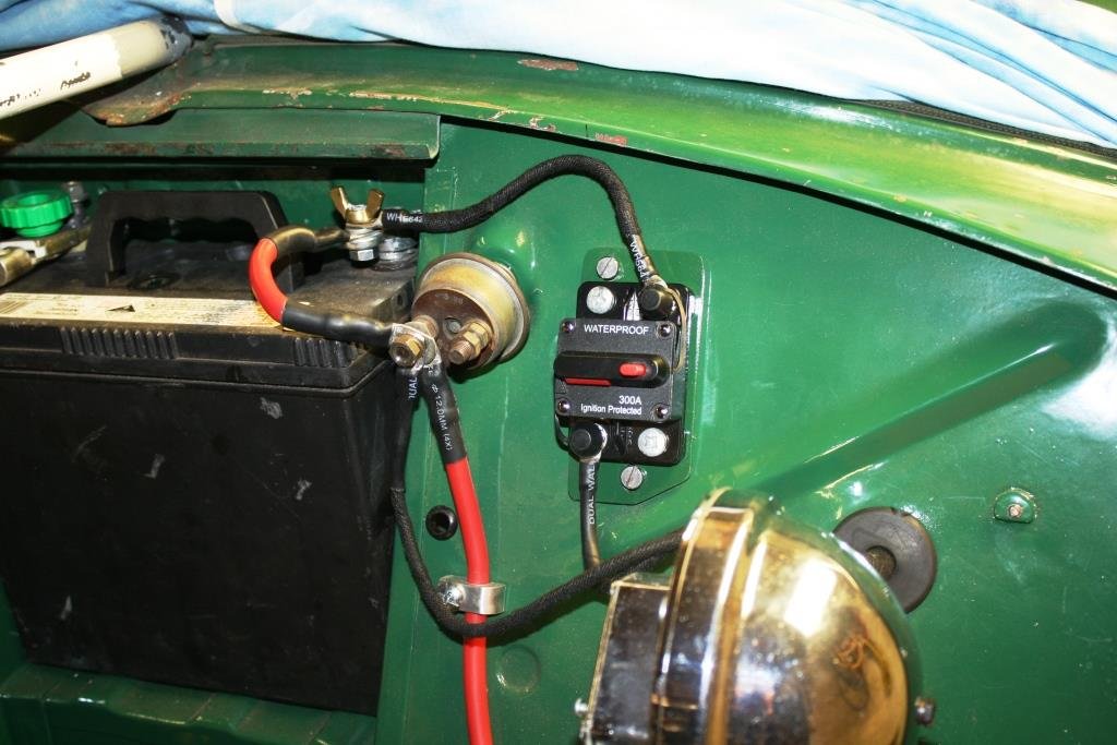
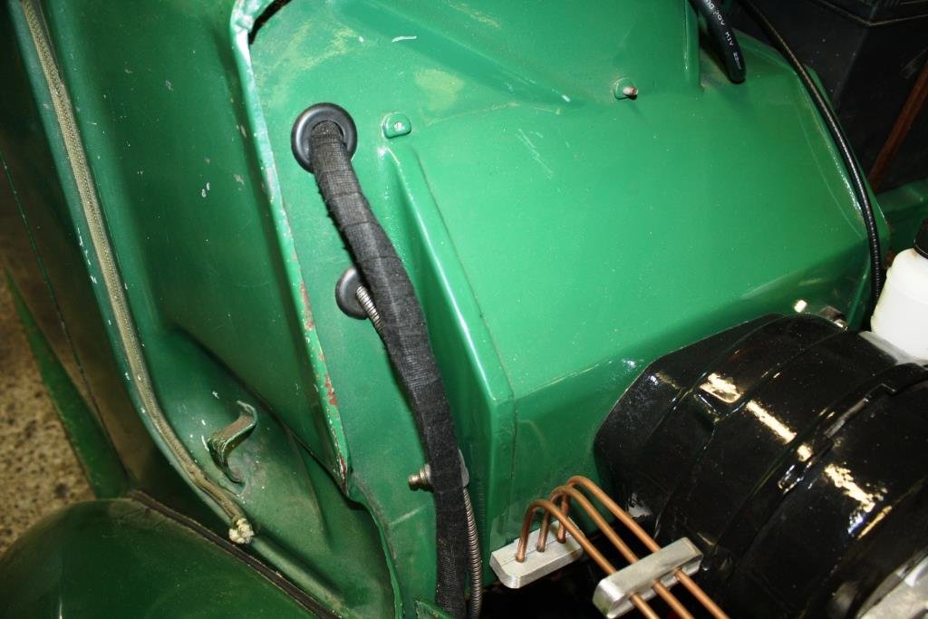
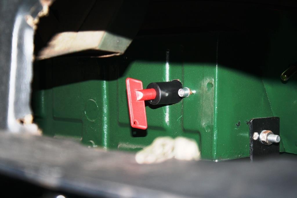
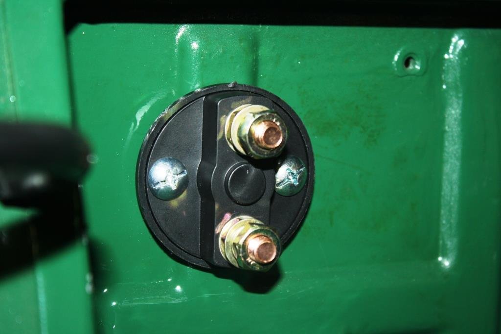
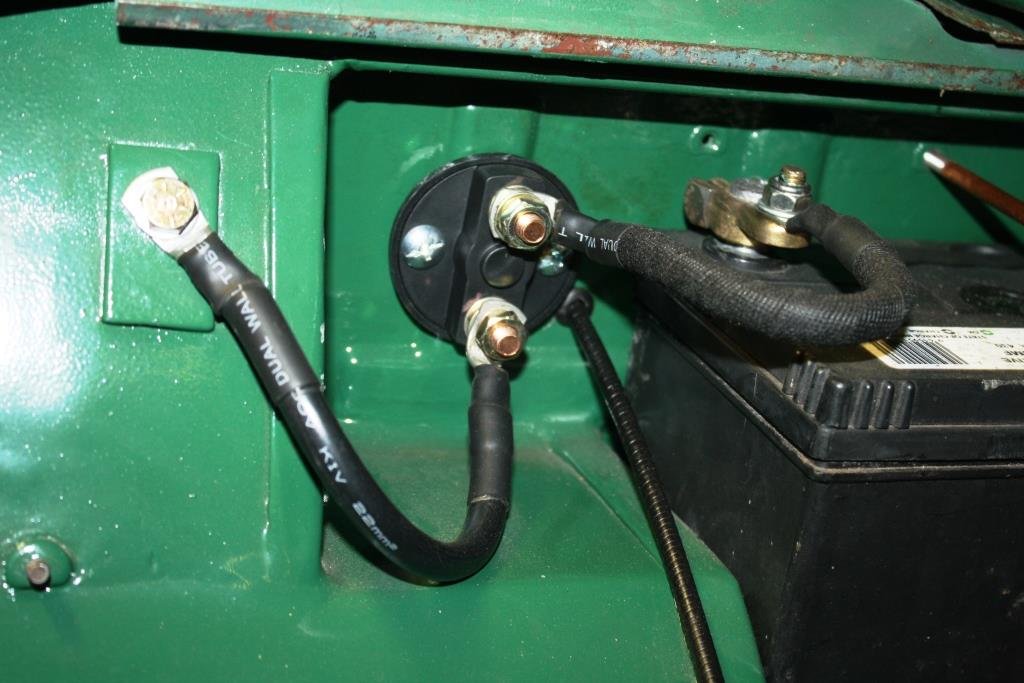
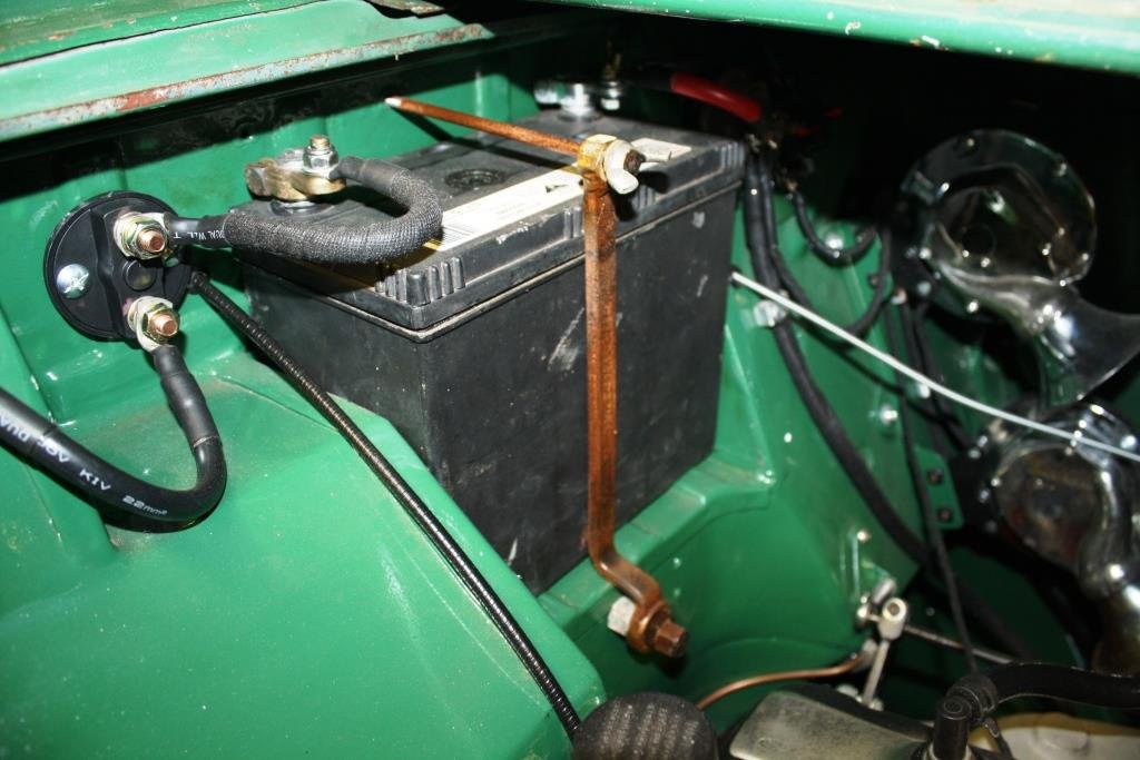
…………Yes I know I’ve been a slack prick, re: this thread. With final arrival of summer the good ship Aquaholic insisted that I take her and some of my disreputable mates out fishing… (What could possibly go wrong?). It was a hot day, we got thirsty, we drank heavily and we “got fush”…….(as you do). A few days later my brother turned up at the Viaduct in this bloody monstrosity, and the good ship Aquaholic (and a certain part of my anatomy) felt very, very, …. small…….(Sibling rivalry can get complicated!). ….so we headed north. The view from the bridge was cool…… Accommodation wasn’t too shabby…. …. And the lounge was bigger than the one at home… Thankfully there was a bar on board for self medication! Back home I was stricken with a bout of the much feared “home handyman-itis” and I accidentally started rebuilding the front of the house… (Note the cunning accumulation of Brownie points with the “ever lovely Mrs. sr2”). After the above brief hiatus I’m finally back to Rigamortice’s wiring. I’m trying to document as much as I can because my memory is like a sieve. I managed to source some cool old fashioned bullet connectors…. I’m almost finished under the dashboard, getting sick of working upside down. The dip switch still works so I hit it with some contact cleaner and we’ll see how it lasts. I’m running relays on the lights so it won’t be carrying the amps that it used to. I’m using my 70 year old meter just because I can. The horns are all wired up but they sound like two strangled cats, I’ll have to do some research on how to tune them. Circuit breaker in place instead of a fusible link. Mounted the battery earth cut out through the fire wall Repurposed an old offset ring spanner for a battery clamp. Managed to get some life out of the interior light with a new bulb and fresh wiring. Cleaned a ton of crud of the diffuser…. And it works.
15 points
-
Clutch cover is away getting stiffer springs put in. I have ordered many specific X1/9 bits from a UK company that pretty much only do X's and Lancia Montecarlo's. So many little things that I was going to have to fudge and now won't have to, so thats nice. In the last couple of days I slapped the last of the paint on so it is (mostly) one colour, and this evening has been all about bolting shit back on. Quite a few little trim bits seem to be missing but nothing to prevent function or legality so far. Nice from far, far from nice.9 points
-
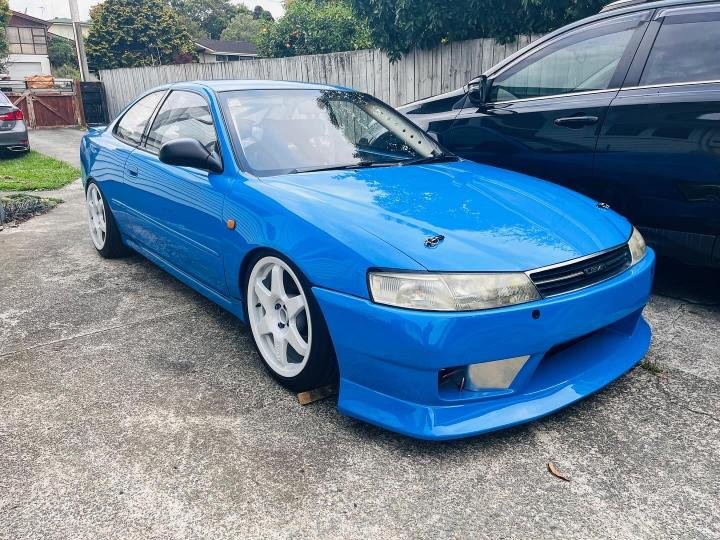
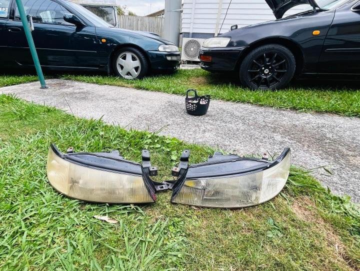
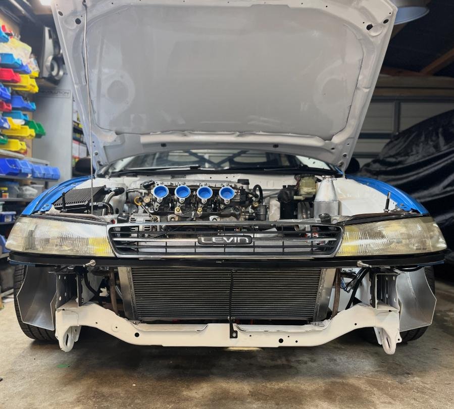
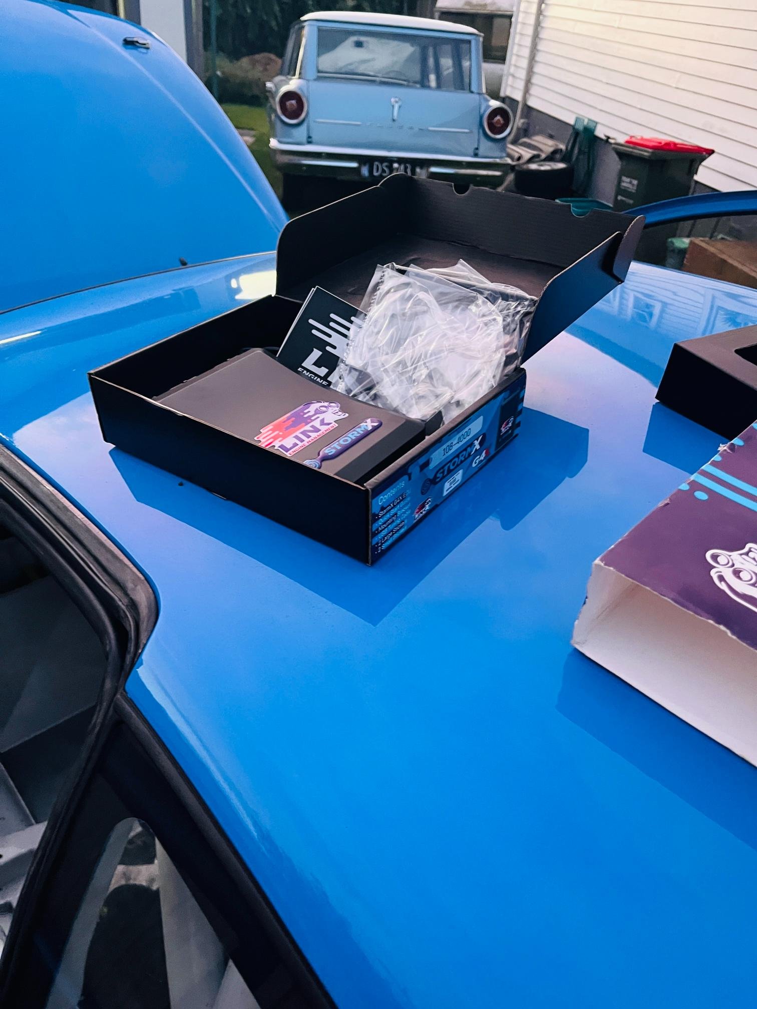
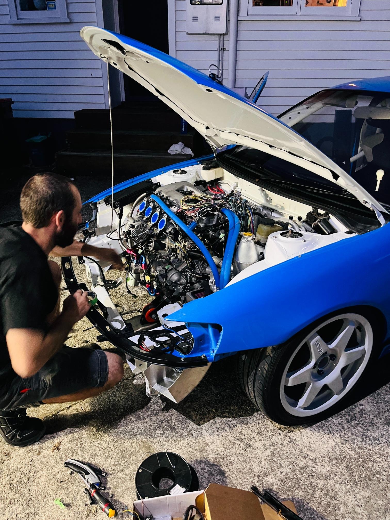
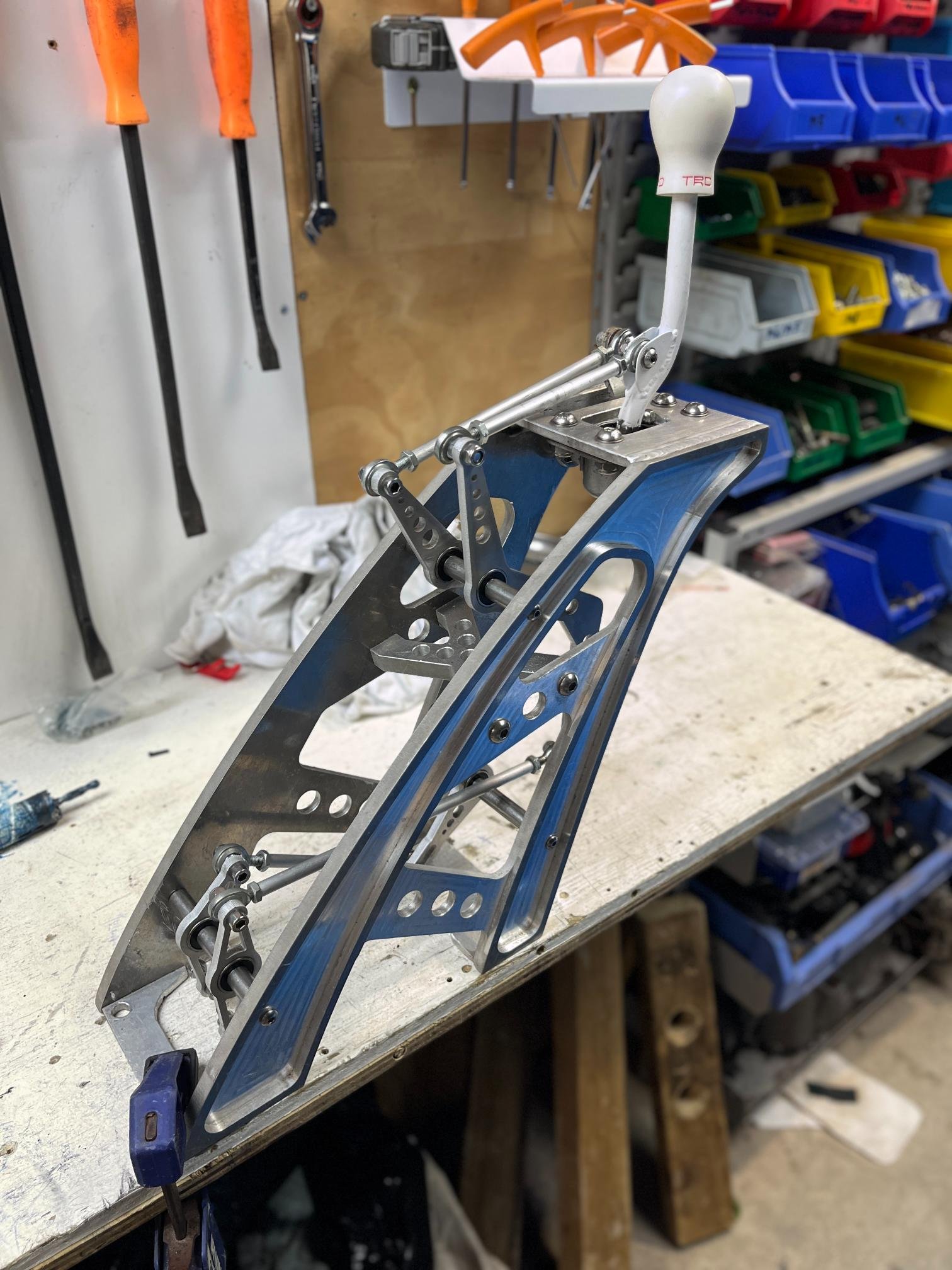
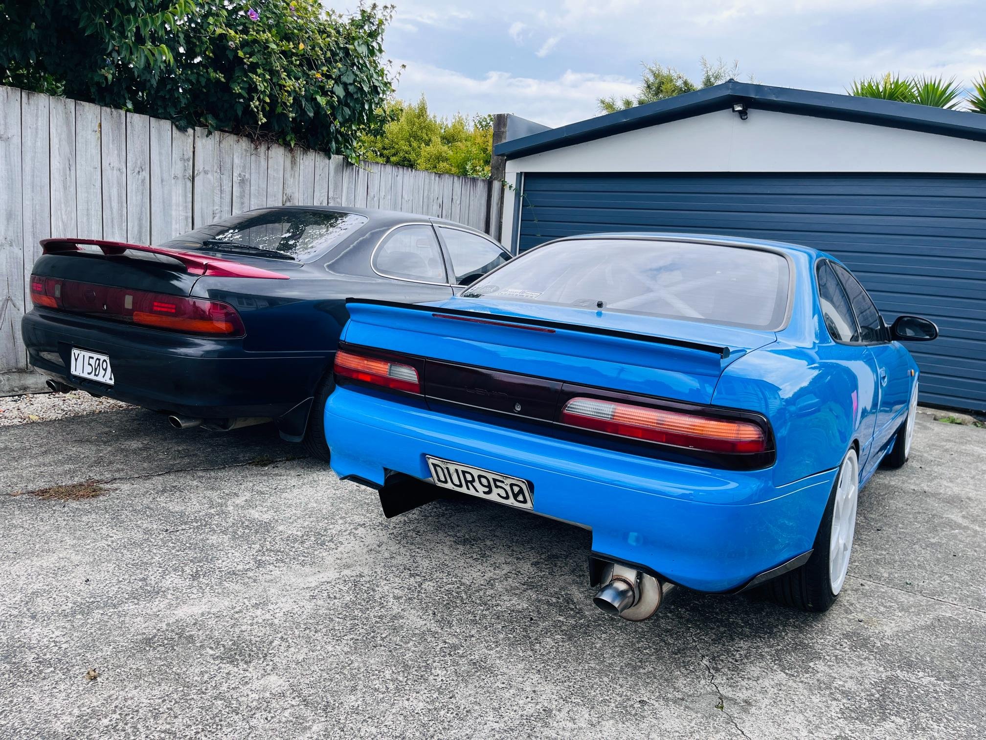
Lots of finishing details taking lots of effort with this project. Stuff that's been sitting on the shelf 'finished' for a few years always needs adjustments or I need to remember how it was supposed to be installed... Final adjustments made to the gear shifter. Locked skateboard bearings in place with Loctite (they are a gentle press fit). Also replaced axle seals and got driveshafts in place. Gearbox is ready to roll once I add some oil... Polished up the headlights finally. Look great, but could be better still. Repainted mirrors in repco 'trim black'. Turned out great! Decided to paint gurney flap black as well. Not sold on it but unsure what other options would look any good? Also, its amazing to see how unlike this car looks like a factory Levin... Dropping a car 4" will do that! Pulled the front apart to do final welds on headlight frames. All comes apart in less than 30mins which is great. Wasn't stoked to need to remove radiator again though (it's a bitch of a job!) And because I hate AN fittings & braided hose.... I sourced some Continental heater hose for breathers (not rated for oil but is no pressure and has 150deg C temp rating so should be fine). Bonus that it comes in almost an exact colour match to my car. Still one more hose end to fabricate for the final breather. 2zz has an obscene amount of breather ports so why not use them all!? Less crank pressure = more power. Last night Drew popped around to do a final measure up on engine loom. Added a few things and adjusted the factory loom to suit. He also brought some goodies with him. This is probably the biggest financial piece of the puzzle left so happy to make this step. Assembling the car and touching things up for Toyotafest at Hampton this saturday. Entered show in 'under construction' category. It's bittersweet because it feels good to finally have something worth showing/sharing with people for my 10+yrs of effort, but still so much work in the finishing touches. Next year I'll be driving it!!
8 points
-
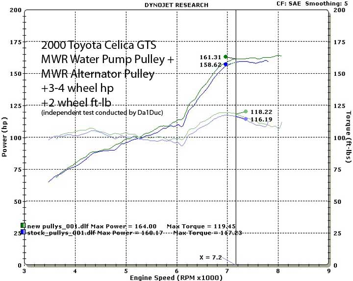
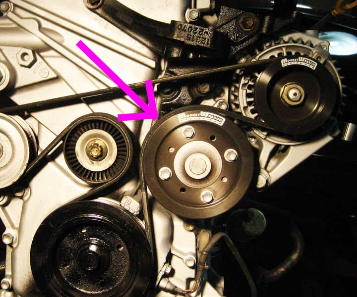
Also quite excited about purchasing alternator and water pump undersized pulleys from Monkeywrench racing. Interestingly, they claim a 3-4HP gain on a factory motor, which combined with my lack of belt-driven powersteering, higher compression, ITB's and exhaust could potentially add up to 5-8hp total. Might even get close to K20 power? This few HP is probably the cheapest $$/kw I'll ever make so stoked to have this piece of the puzzle coming together. These are waiting to make it into our suitcases when we visit the states in a few weeks..
7 points
-
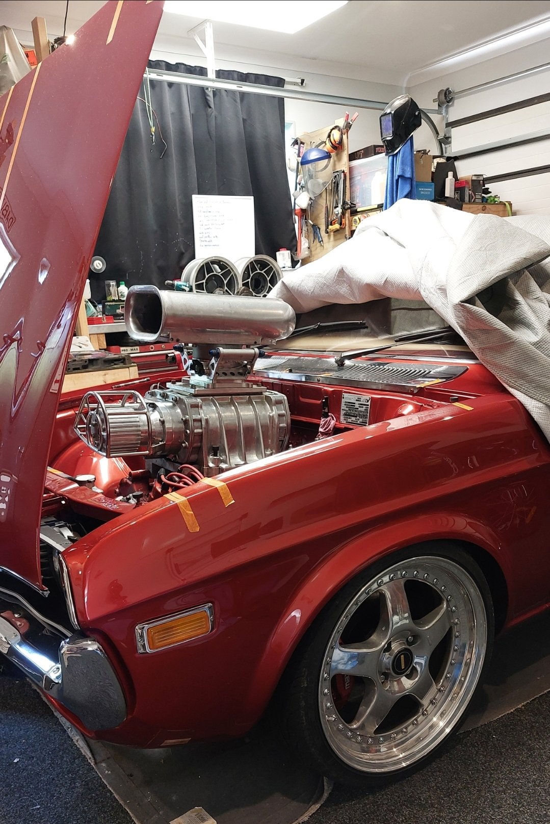
I actually have another good bonnet, and was going to - cut, panel, paint that one, but thought what's the point, as ill just cut the one on the car, and I wont need to do any panel or paint. If (I Wont) I ever need to fit a normal bonnet then ill just panel and paint the spare when the time comes, saves spending 2-3k unnecessarily now5 points
-
4 points
-
4 points
-
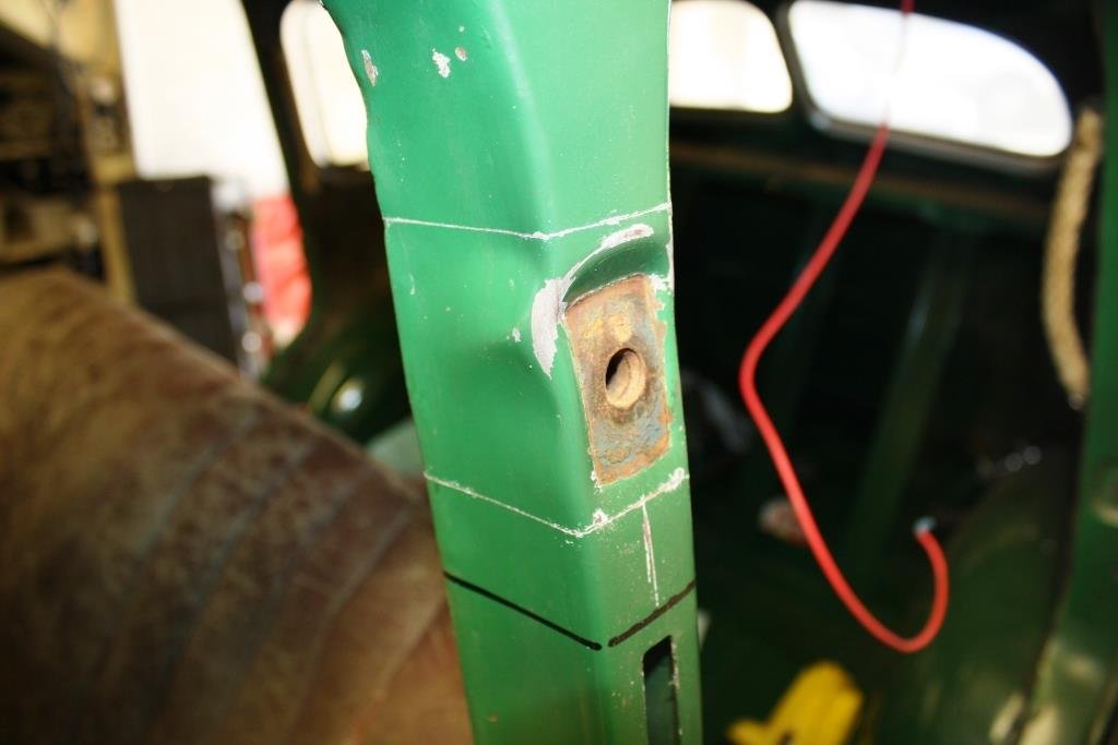
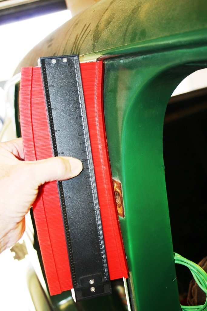
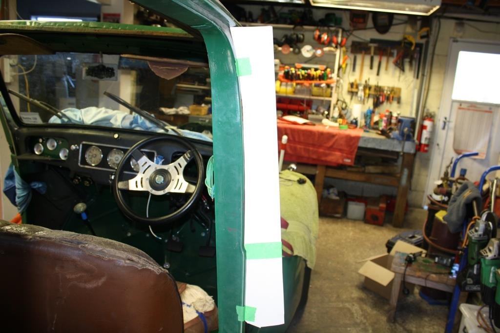
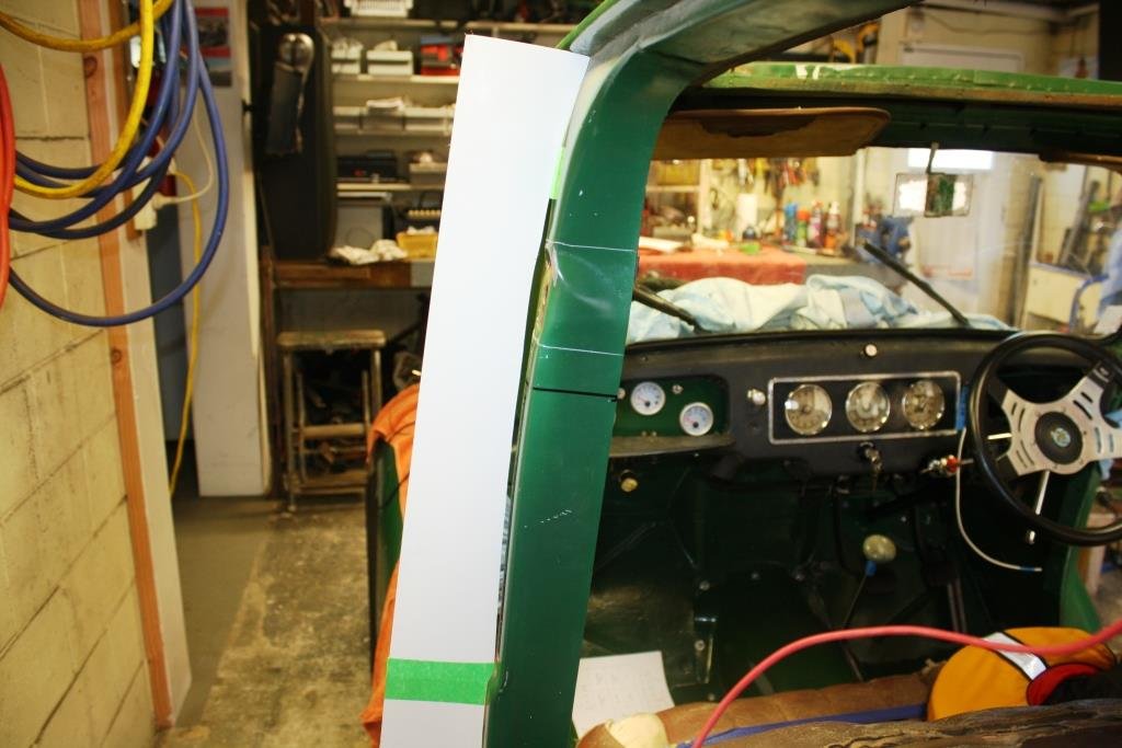
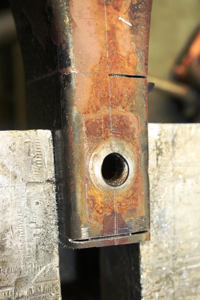
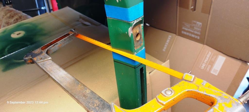
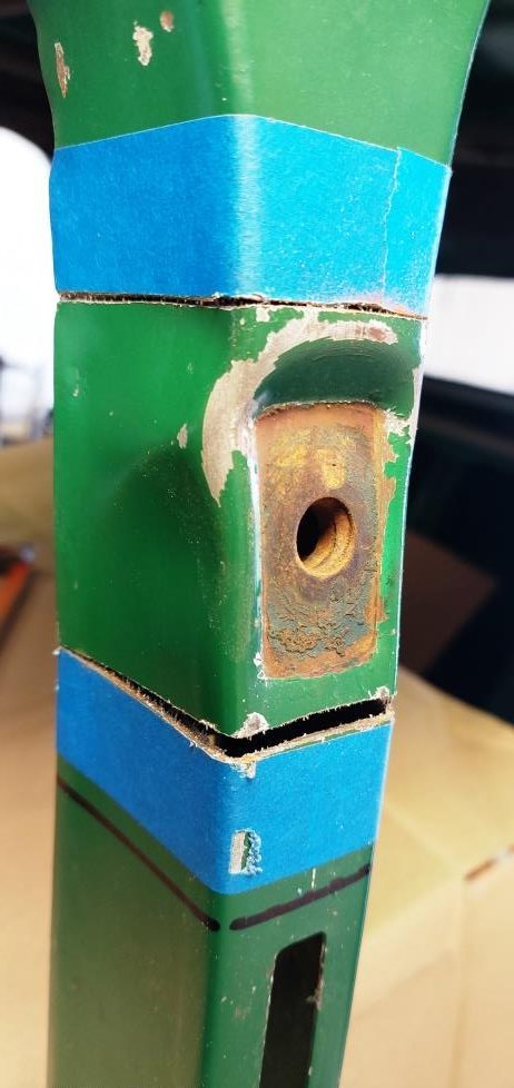
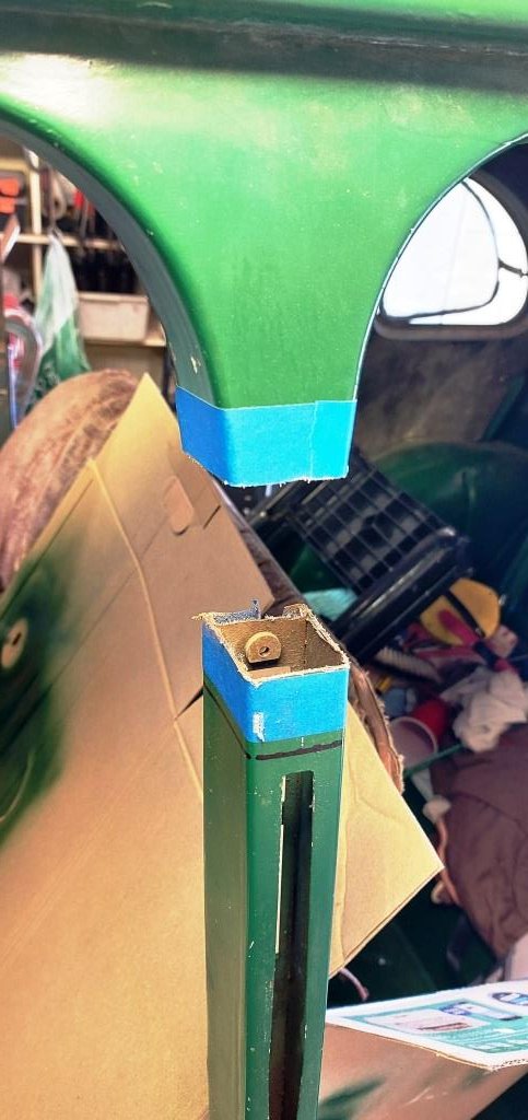
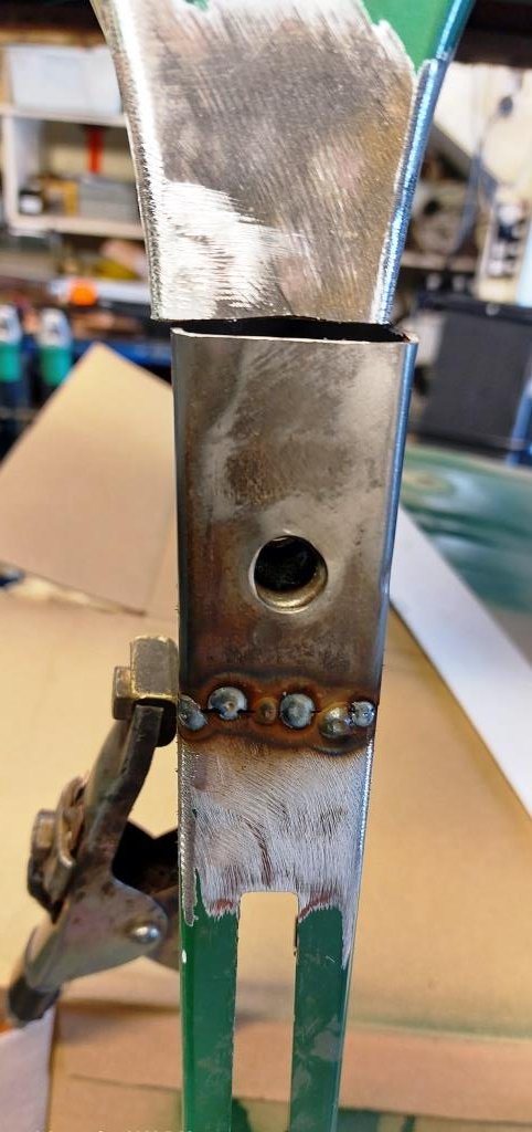
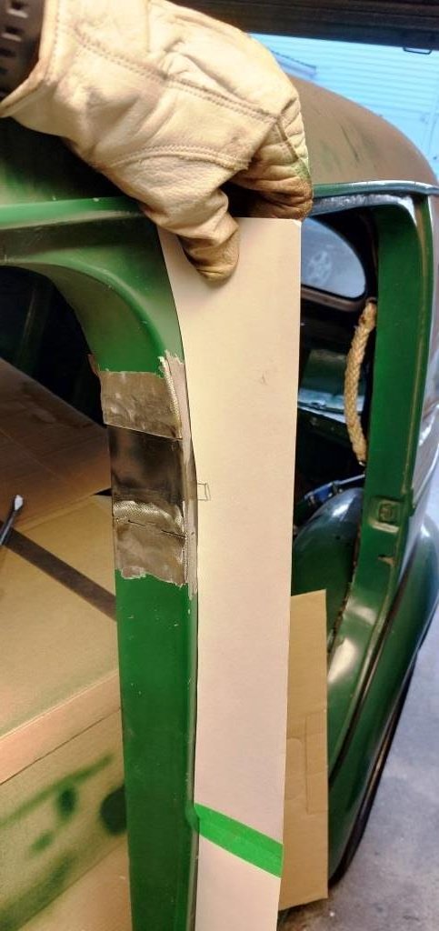
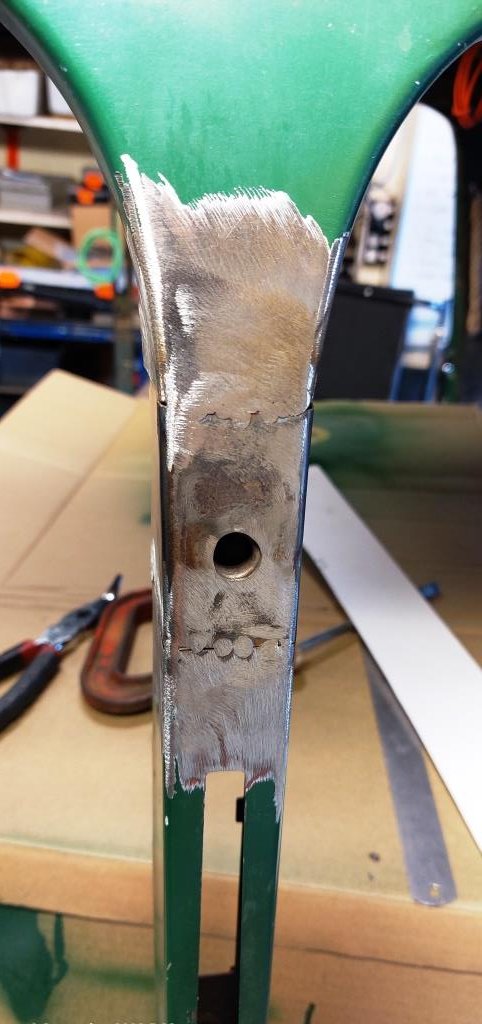
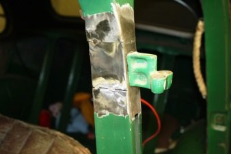
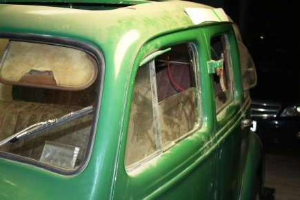
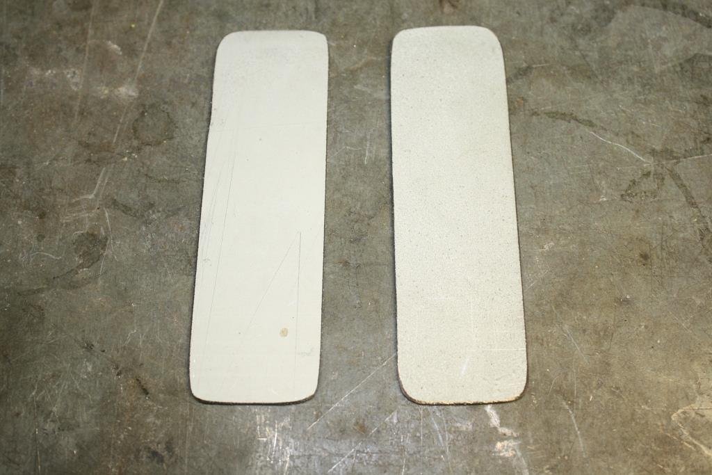
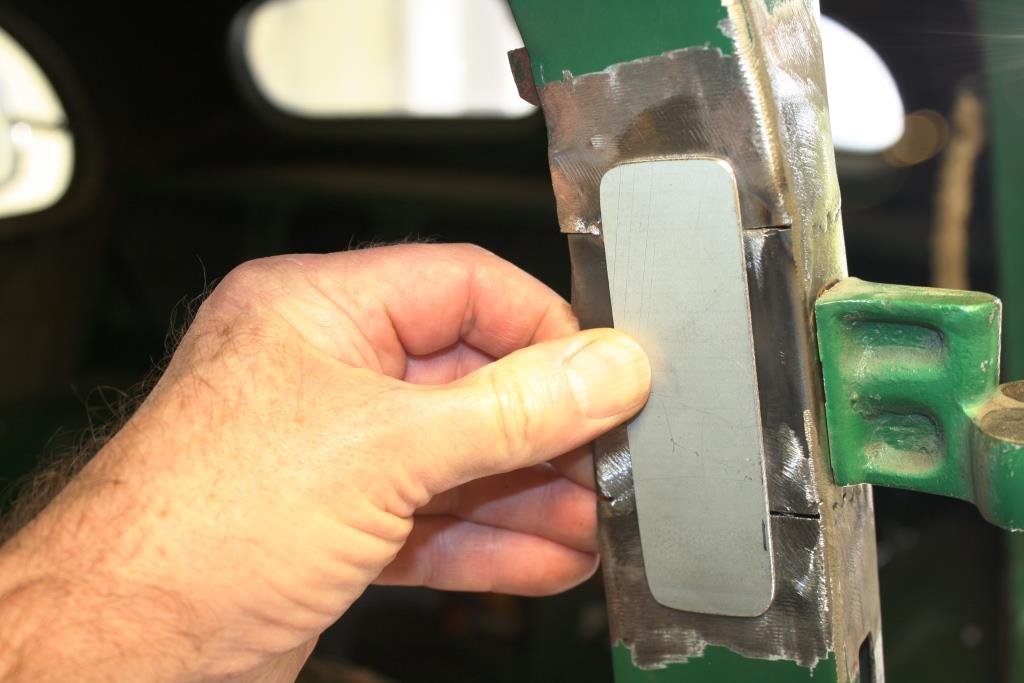
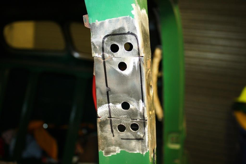
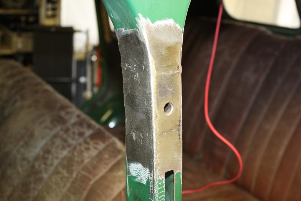
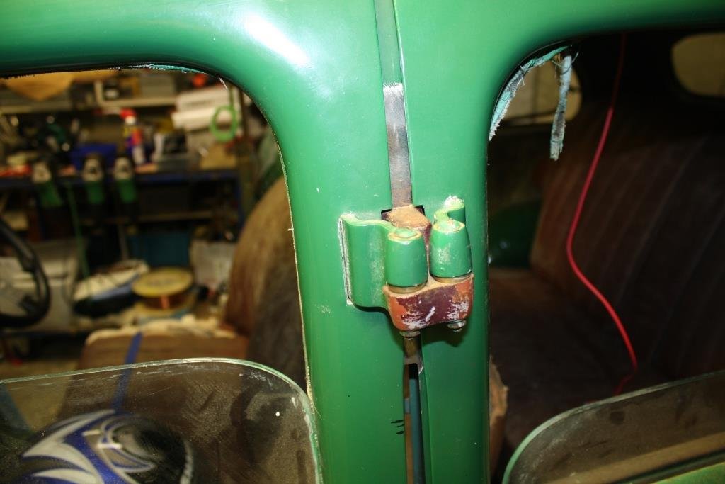
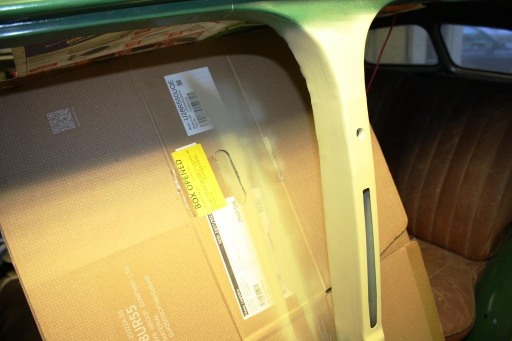
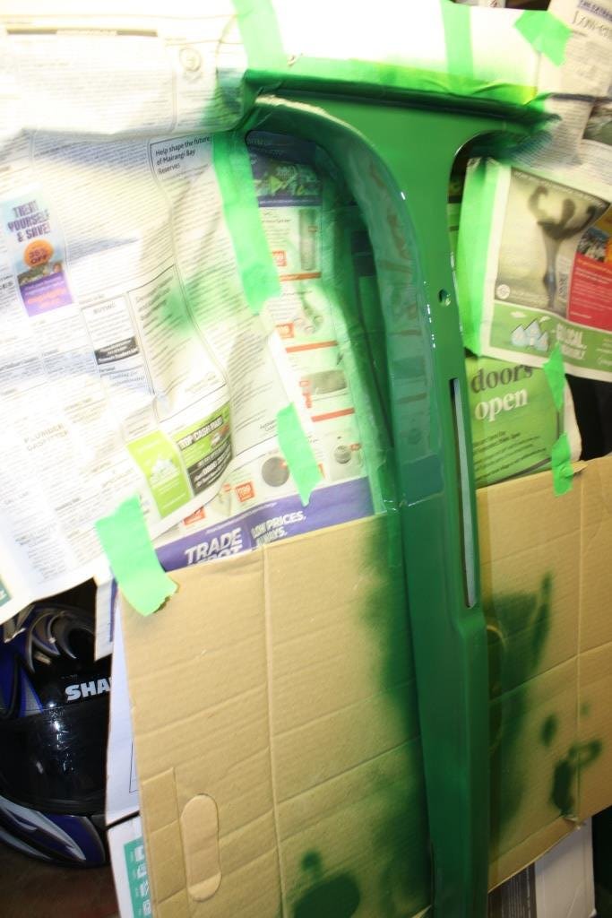
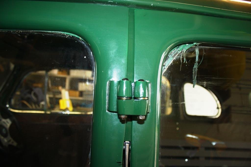
Time to take on a job I’ve been dreading somewhat; repairing the damage to Rigamortice’s port side B pillar that was the result of the body falling off my homemade body rotisserie. I used a profile gauge on the good side…….. Converted it to CAD……. Swapped sides…….. …. And it was easy to see how out of shape things were…. After a lot of measuring I cut a section out of the replacement B pillar…. And did the same on the car. I went back to using an old school hacksaw - far more accurate than an angle grinder for me. It popped out with a bit of a bang, obviously under some tension. Started tacking the repair piece in… Checking it with the CAD template…. Still just little tacks, a bit messy but I’m cognisant of avoiding putting too much heat in and distorting things. A quick test fit of the doors and it looks OK. Cut out some 16 gauge zintex strips… Marked out and drilled for plug welds.. Put the reinforcing strips inside the pillar and started welding……. A quick test fit of the doors and nothing has moved….(phew!). A few coats of sandable primer… The obligatory insipid green… Doors finally back on and everything fits.
4 points
-
3 points
-
3 points
-
3 points
-
3 points
-
3 points
-
3 points
-
3 points
-
I glooped the two halves together, bolted them up, bolted the tailhousing on and let it set. Following morning it was bolted onto the engine, unsurprisingly a bit heftier with all the gubbins placed back within the box. Its about 9kg heavier than the standard imp box. I then started to fit the first part of the gearshift linkage. The first of those snazzy universal joints, handily available in a diameter to suit the shifter shaft on the Subaru box. I just needed to add a small locating hole for the grub screw... Universal in place.. Engine and box were then bolted back into the car. This bit is so quick and easy when using the 'engine stand 2000'. It takes about 10 mins and I'm getting quicker. It'll be slower when there's shift linkage to undo and driveshafts to slip out of the way. But at least the main heavy awkward part is actually easy. That lot in place I took some pics. Its neat to be able to look out from the one of the lounge room windows down onto the workshop floor and see this... With that lot in place I was able to suss out the angles I could get away with, as shallow as possible and allowing for the handbrake mechanism. I had this old imp gearstick assembly that @dmulally kindly posted over to me. Some previous owner of the car he got it from liked painting things. Everything. Multiple times... I scraped all the layers off, took it apart and cleaned off the dirty old grease. Discovered it had been cobbled together from two old shifter bases. It was originally a very early Imp unit when the very first cars had an automatic choke, which often proved problematic. Hillman then changed the cars over to a manual choke with a nifty little lever in front of the shifter. This mount had been added to the early base. Which means they must have chopped up a later baseplate to get the choke mount. Why they didn't just fit the entire newer base plate I don't know. But what I had in front of me was a frankenstein of base plates with barry spec welding and fixes, but also including a not too badly made bronze bush on the lever where there is normally a (wornout) plastic bush. I had a couple of shift rods to choose from. I chose the least worn. Moving back to the gearbox end I machined up some shaft ends from stainless bar to suit the universal joints. I had some stainless tube and welded the ends in place on the first shaft that runs from the gearbox universal down to the tunnel. Now I needed a sturdy, slippery support to mount in place of the second universal joint. This will not only take back and forth movement on the shaft but also a bit of thrust loading created by the angle on the connecting shaft. I had already bought a lump of slippery hard engineering plastic with this application in mind when I had ordered the plastic for the flywheel thrust bearing a while back. It was bright yellow. Luckily not seen under the car as it would clash with the blue paint. I put a hole in it and machined the outside down. Which also created a pile of pretty swarf.. Then reamed it out to 1" Still a bit tight so out with the adjustable reamers.. until it was just right... Then made a stainless cradle .. The cradle got some wings welded in place and I dug the rivnut tool out.. Mount now bolted in place in the tunnel I had to chop the last tube to the right length, weld on the end and bolt the universal in place.. The front end below the shifter was was standard imp stuff and this is where problems popped up to throw a medium sized spanner in my workings. The side to side gearstick movement across the gate was minimal. Ridiculously so. Like about 1". Or 25mm in new money. Yet the fore and aft movement was about right. But quite stiff. I was contemplating why this was so and what I could do to remedy this when I also noted that 1st gear was where 3rd was and 3rd was where 1st was. Poos. Four years ago when I had compared the Subaru gearshift pattern at the box to the imp unit I thought they were exactly the same. But I had not accounted for the reverse rotation taking place under the imp gearstick. Also I never really thought much about how little of rotation the Subaru box needed on its shifter shaft to shift the internal selector across the 3 rods. Its a tiny amount, like 3 degrees say. Whereas the Imp box has a shorter internal selector and requires more rotation at the shaft. Hence the Imps gearstick knob only moves a teeny bit when coupled to the Subaru box. But the Subaru box has a standard/similar amount of rod movement within (ie 1-2 and 3-4th) which was going to make things trickier to fix. Simple linkage/leverage multiplications that is easier to see than explain. Sorry if your brain hurts. I had to hurt my brain a little bit to suss out a solution but there was only a little bit of smoke. The reason the scooby box is different becomes obvious when you see the scooby shifter setup. Which luckily I can show you because last week thanks to @Leone I was put onto a local fella to me who happens to have many old Leones and Brats kicking about his property and he had a spare leone front wheel drive box that I wanted (always handy just in case...) His property is amazing!!! Long 4wd only driveway up to a ridgetop house with stunning views out over Tasman Bay. Old leones just kicking about... Luckily we have our trusty old 4wd Hiace and that became the days gearbox transporter... Box on bench. Look at that shifter mechanism... The shifter rod attached to the gearstick only rotates a tiny amount when the stick is moved sideways across the gate. But the rod moves 10mm in each direction when shifting for and aft. Simple. Robust. Very Subaru. I can't copy it though because I have turned my box 180 degrees. No matter where I put my pivot point (below or above) I'll have one of the planes working backwards. So I decided to build a new shifter base setup. The most important thing was to reverse the rotation so the gearstick pattern is correct. The imp pivot point needed raising to allow the offset shaft end to be rotated to above rather than below the centre line, so reversing the across gate movement. I would add the ability to adjust both rotation and lineal movement. Started with a new pivot cup because I was not happy with the worn and Barried pressed steel item.. I dug out a large lump of steel bar... Chopped out a square and cleaned it up in the mill.. Big drill = big hole.. Rough machined out a cup shape. Cut a form in cardboard to suit the brass ball and used a die grinder bit to finish the shape... Grinding paste time... Slots for pivot pin.. Lightened the lump down.. Built the shaft up with weld and machined it down so I could add a lower pivot point. Milled some steel like so.. Welded a boss on.. New socket for shift lever ball end... Cut out Barrys previous workmanship... Machined up some spacers and a base plate.. Welded up a little tower (my stainless and steel tig welding is definitely improving, helped muchly by realising that not being able to see what I'm doing does not help much and finally admitting to my age and buying some reading glasses....) Welded tower to base.. Now all together please... Bolted together. You can spot the adjustable rotation, which the spacers allow for, along with adjustable pivot point. In place... Yay- it works! The shift pattern is correct and the action is much smoother. The spring loaded indents on the internal gearbox shift rods are quite stiff, which I noted was the same on the other box with its stock shifter. Its a bit baulky to push past the synchro baulk rings into gear but I think will feel better when the gears are actually rotating. There's certainly no slop in the system and it feels very mechanical - not rubbery. I now note how much flex there is around the shifter base in the imps tunnel (granted a very rusty shell..) Its something I might just try to stiffen up on my blue Imp when fitting this lot in. Phew. That was a little mini engineering mission I was not expecting but that's this project in general3 points
-
He's still grumpy as fark now based te puke I think.2 points
-
When i fitted a p12 primera 6 speed to a earlier car, the best way was to cut the cups off the inner cv's can weld the cups on from the car it was going into (p10). Then you have a large diameter weld, rather than small, so much much stronger. Also looks stock. I got ADL in auckland to do them, cost $600 but was well worth it.2 points
-
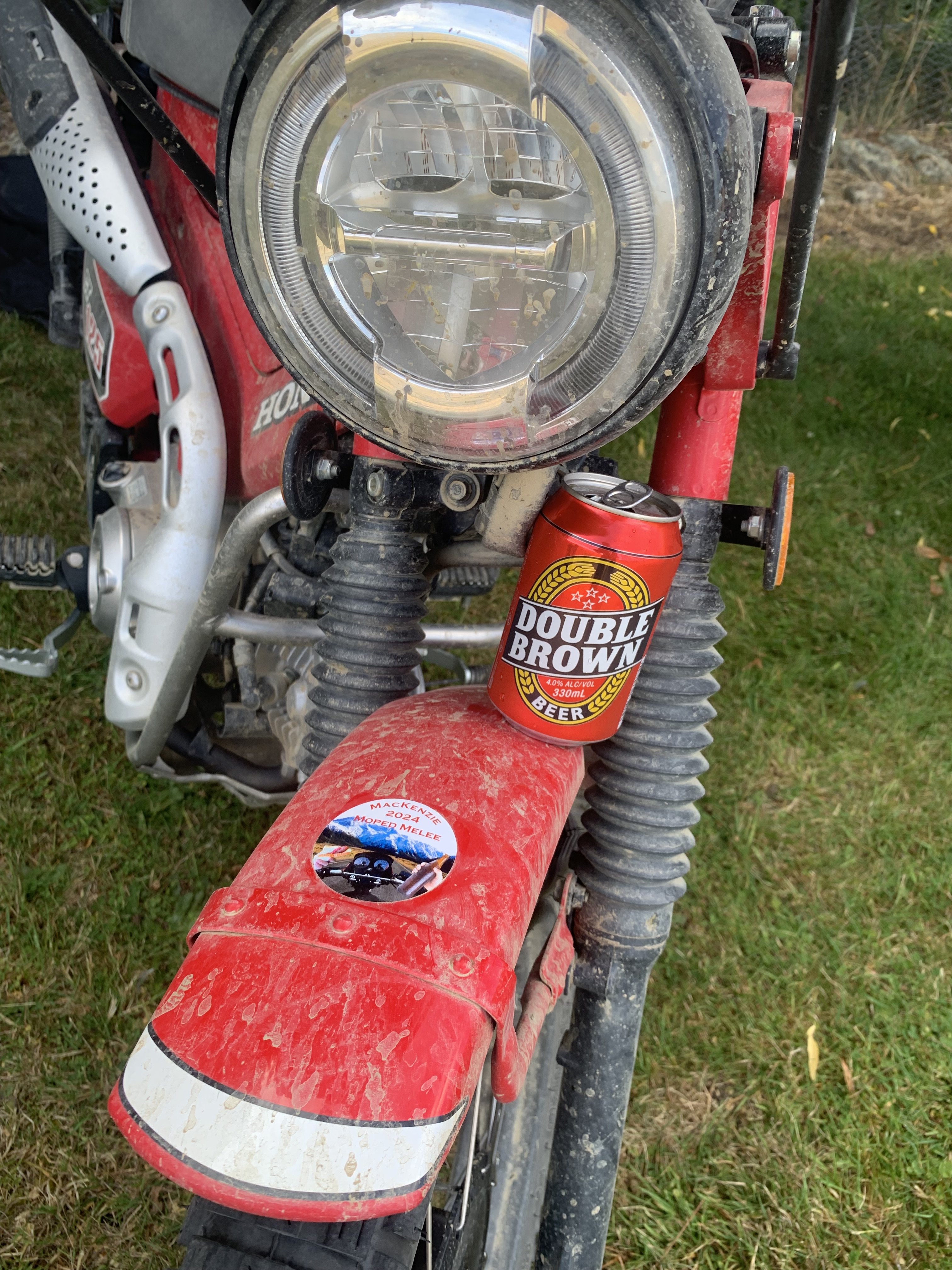
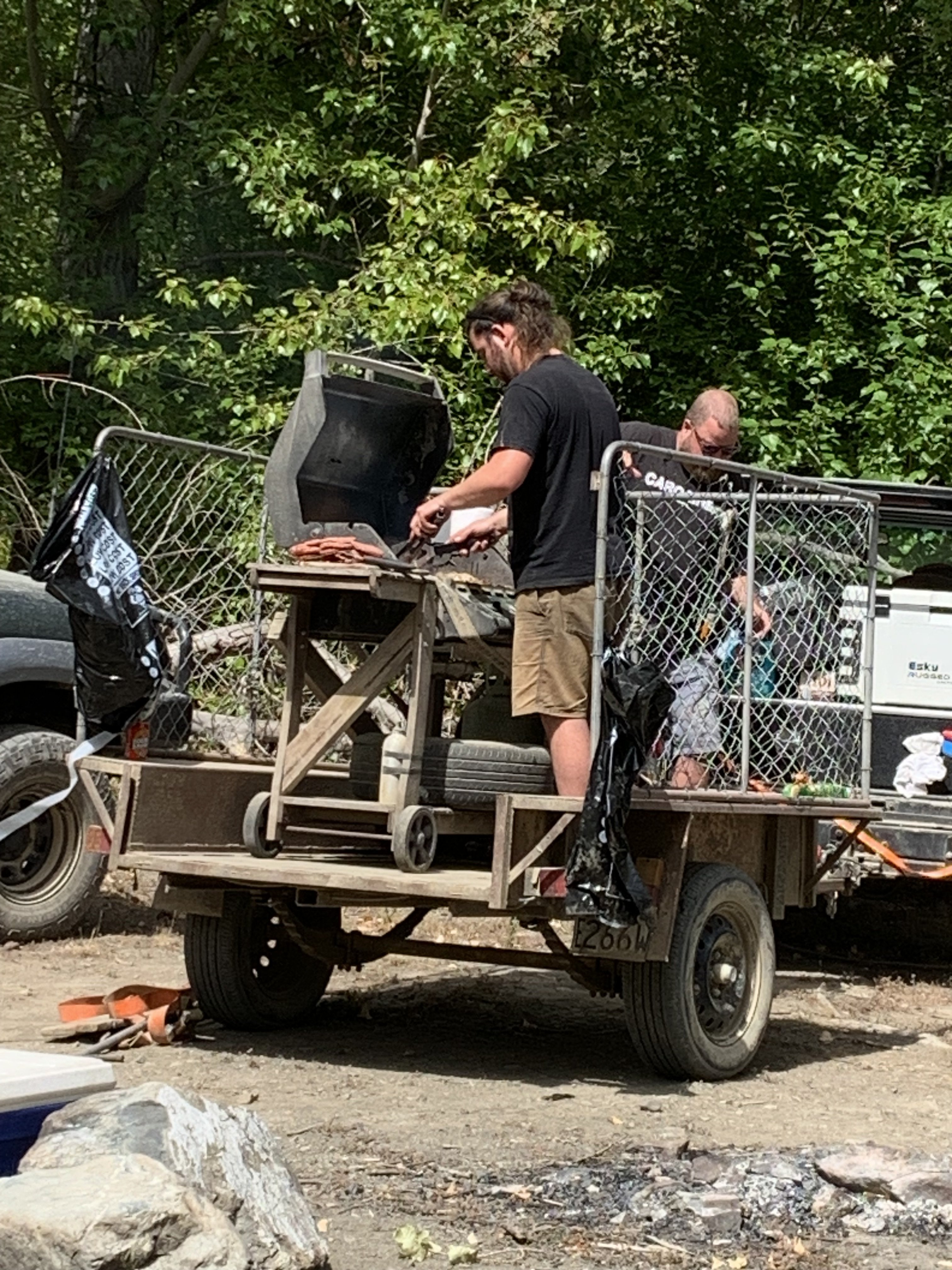
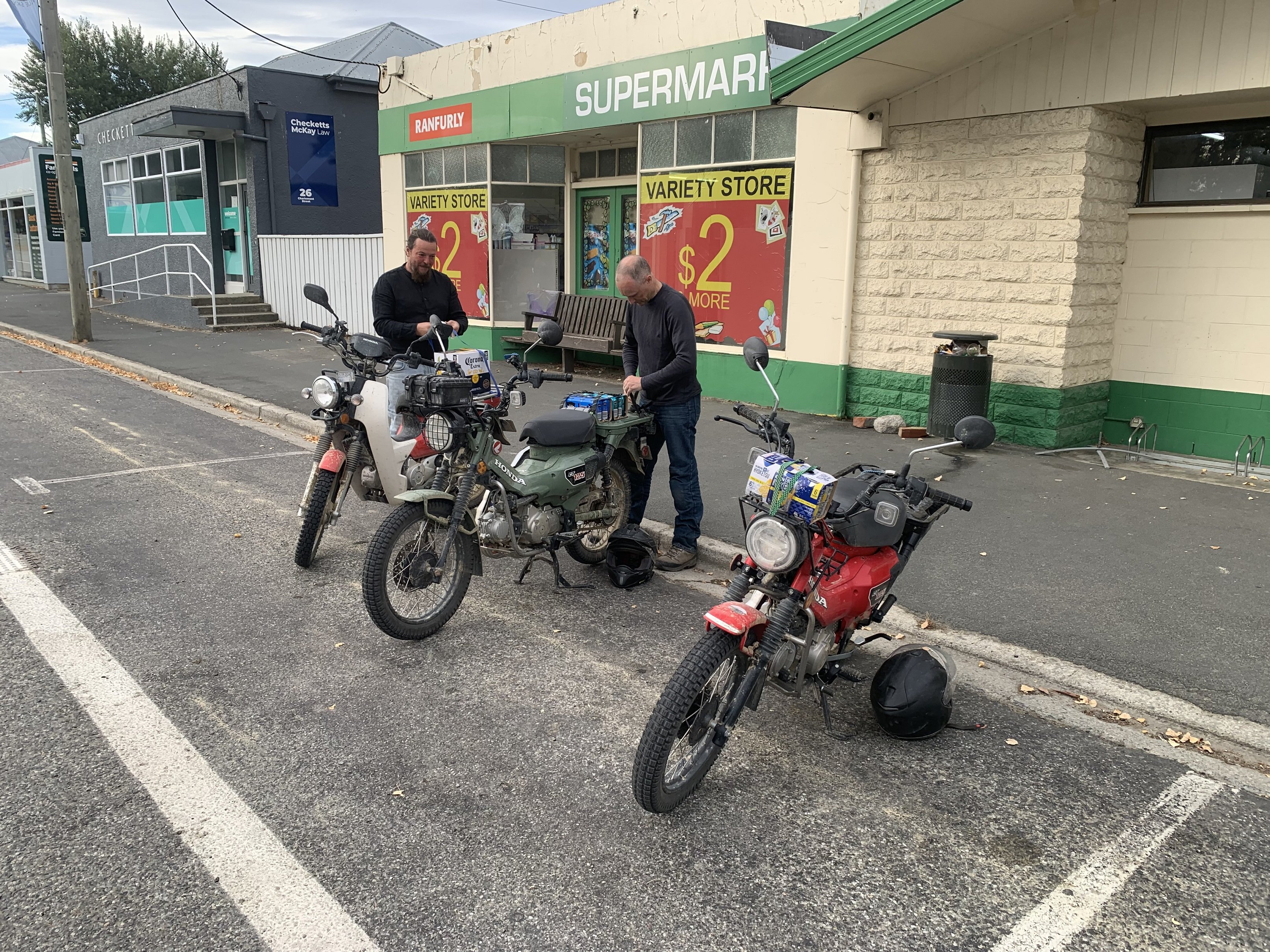
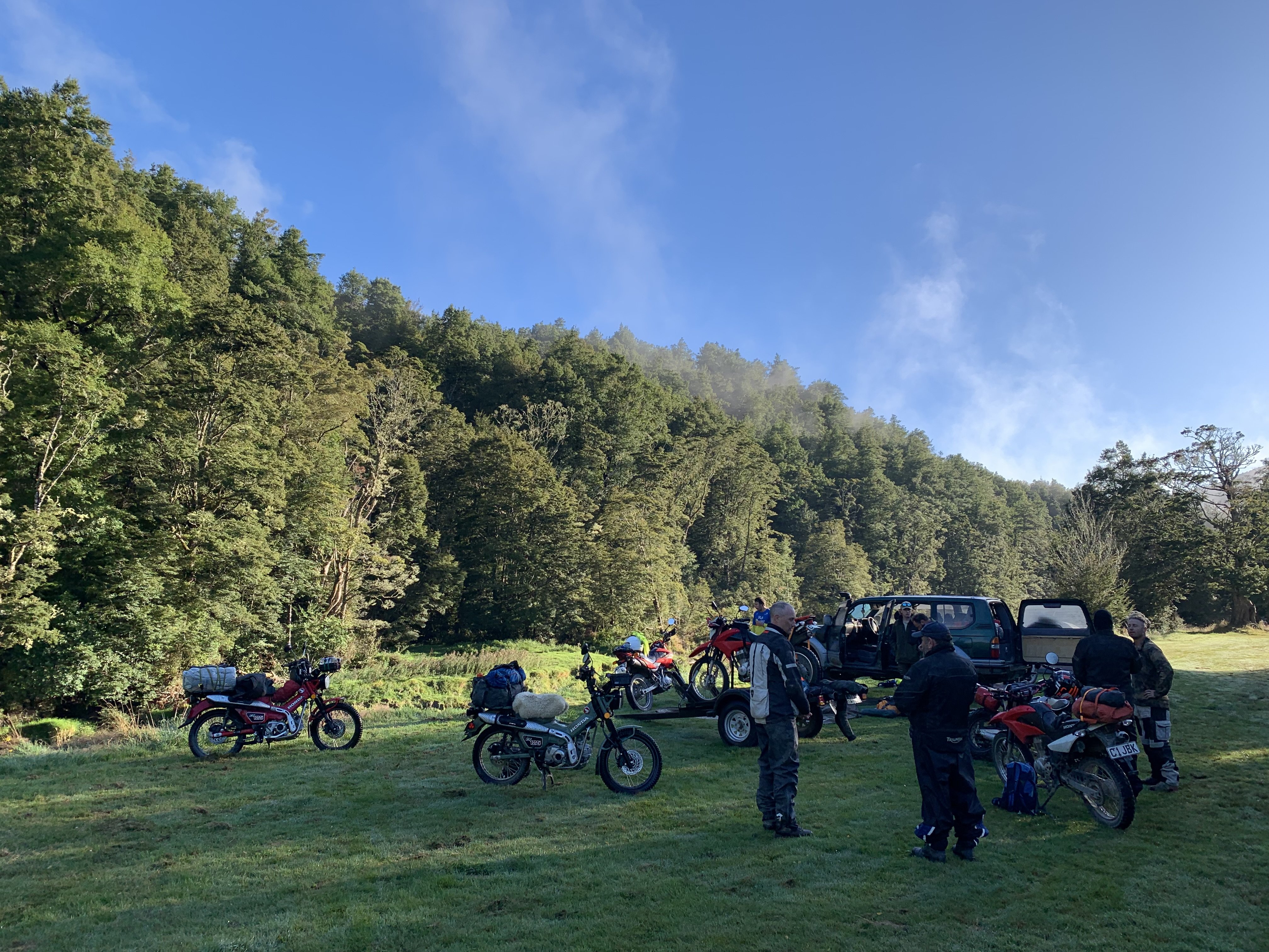
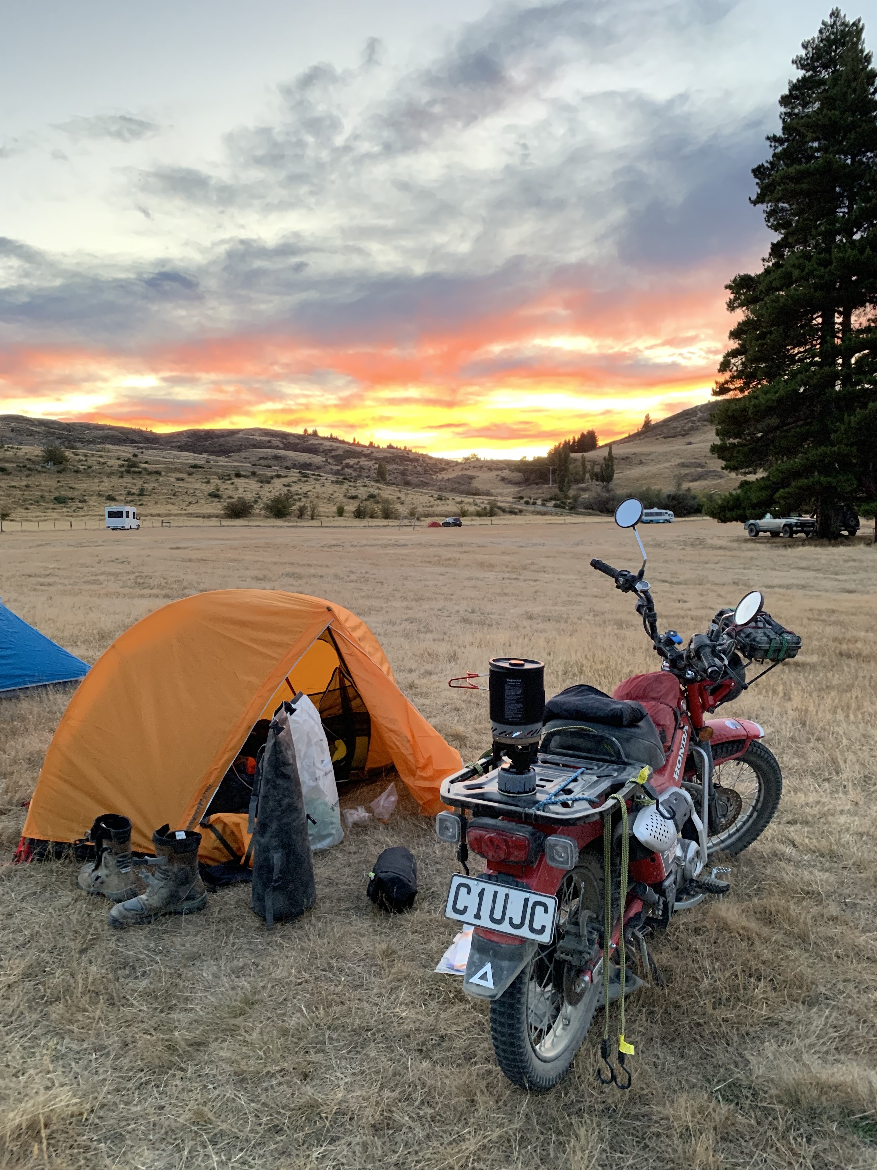
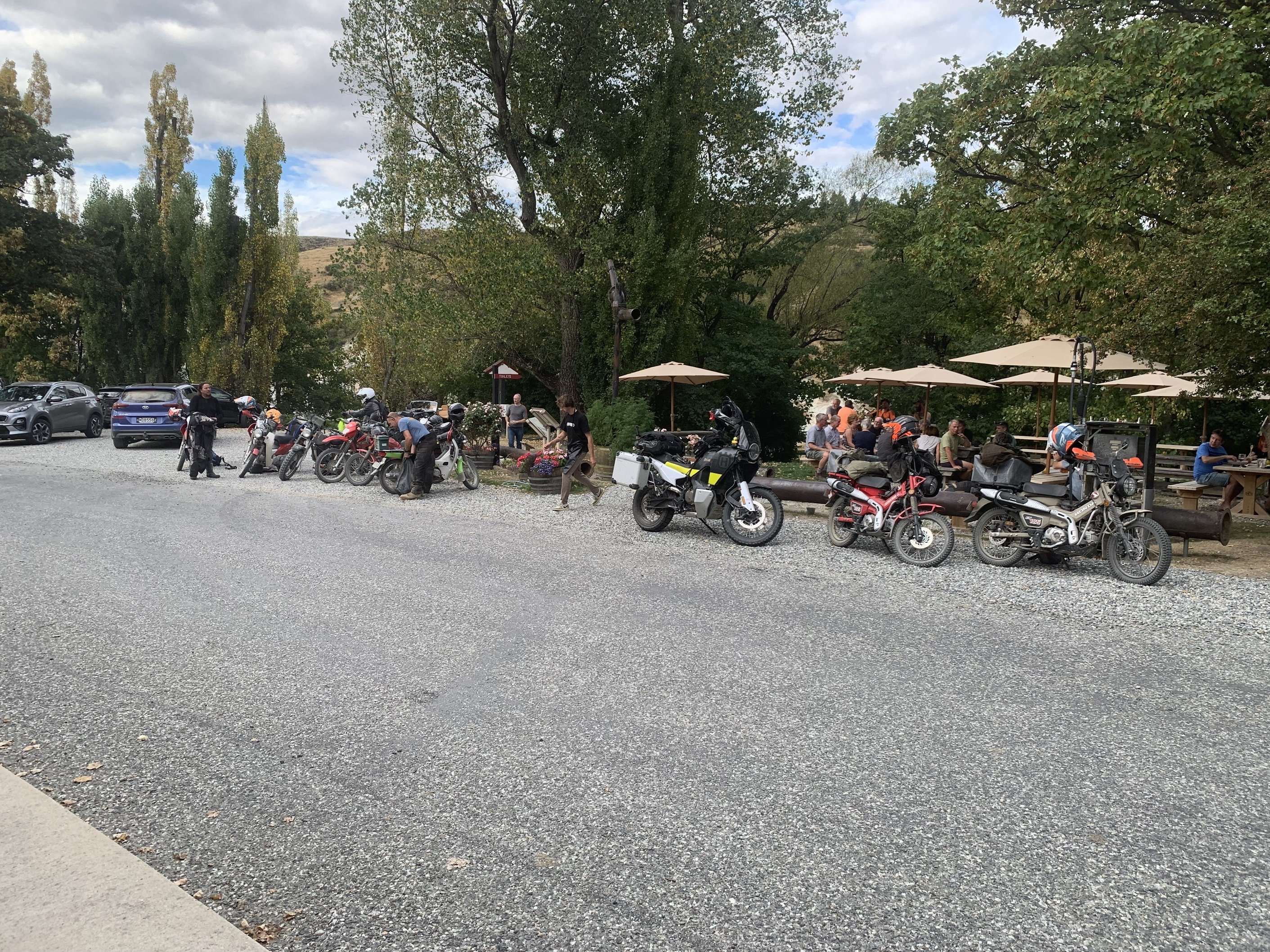
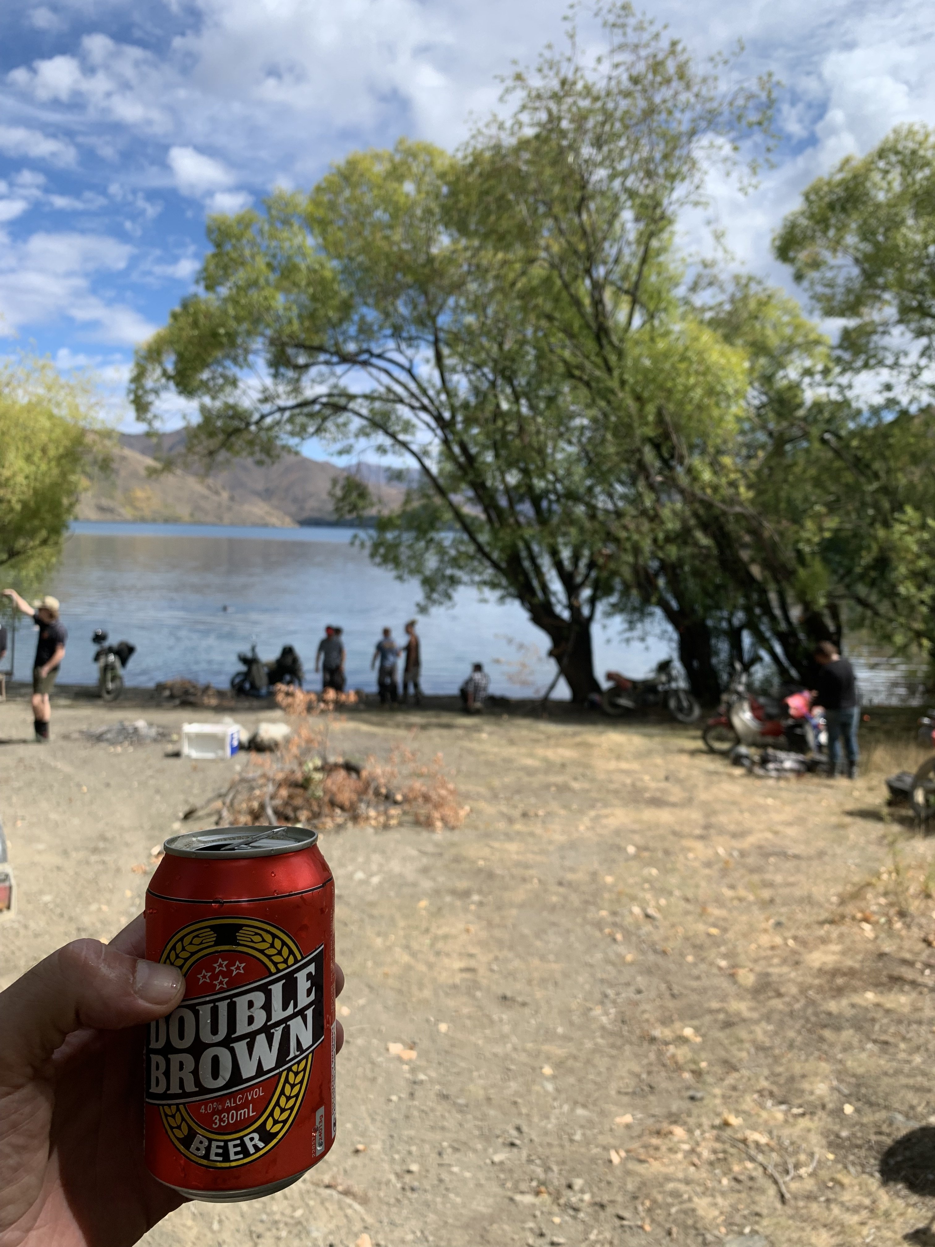
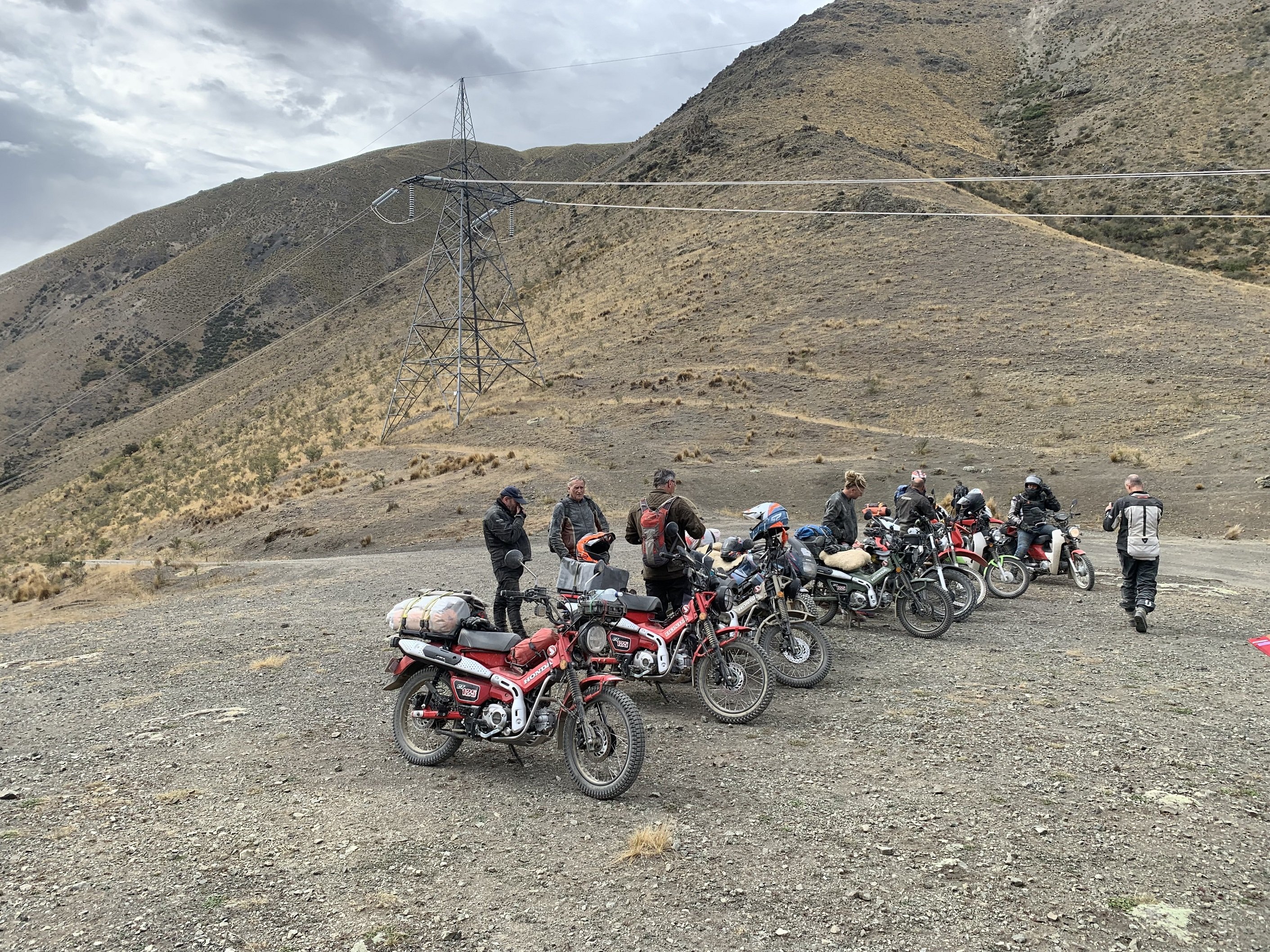
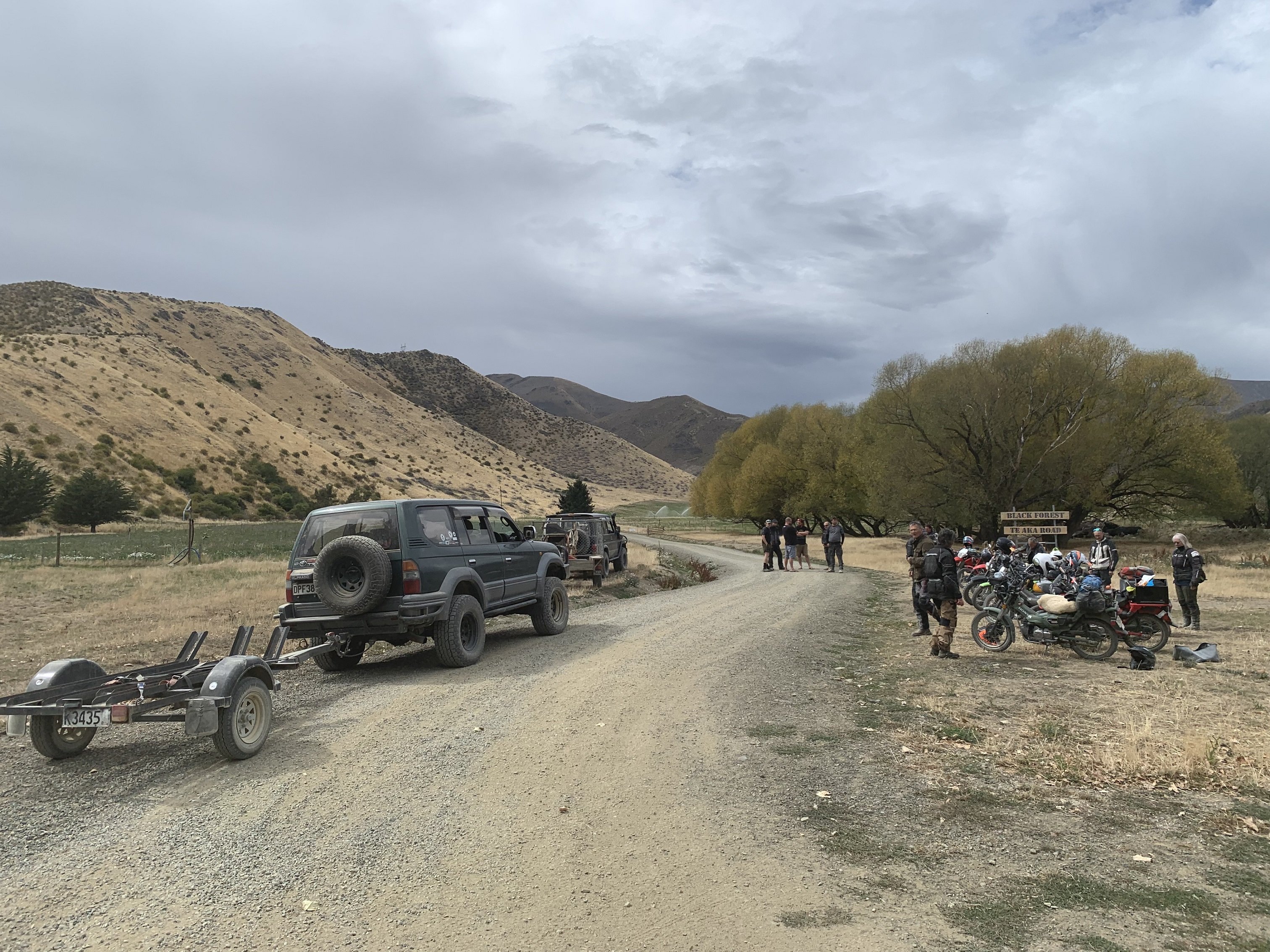
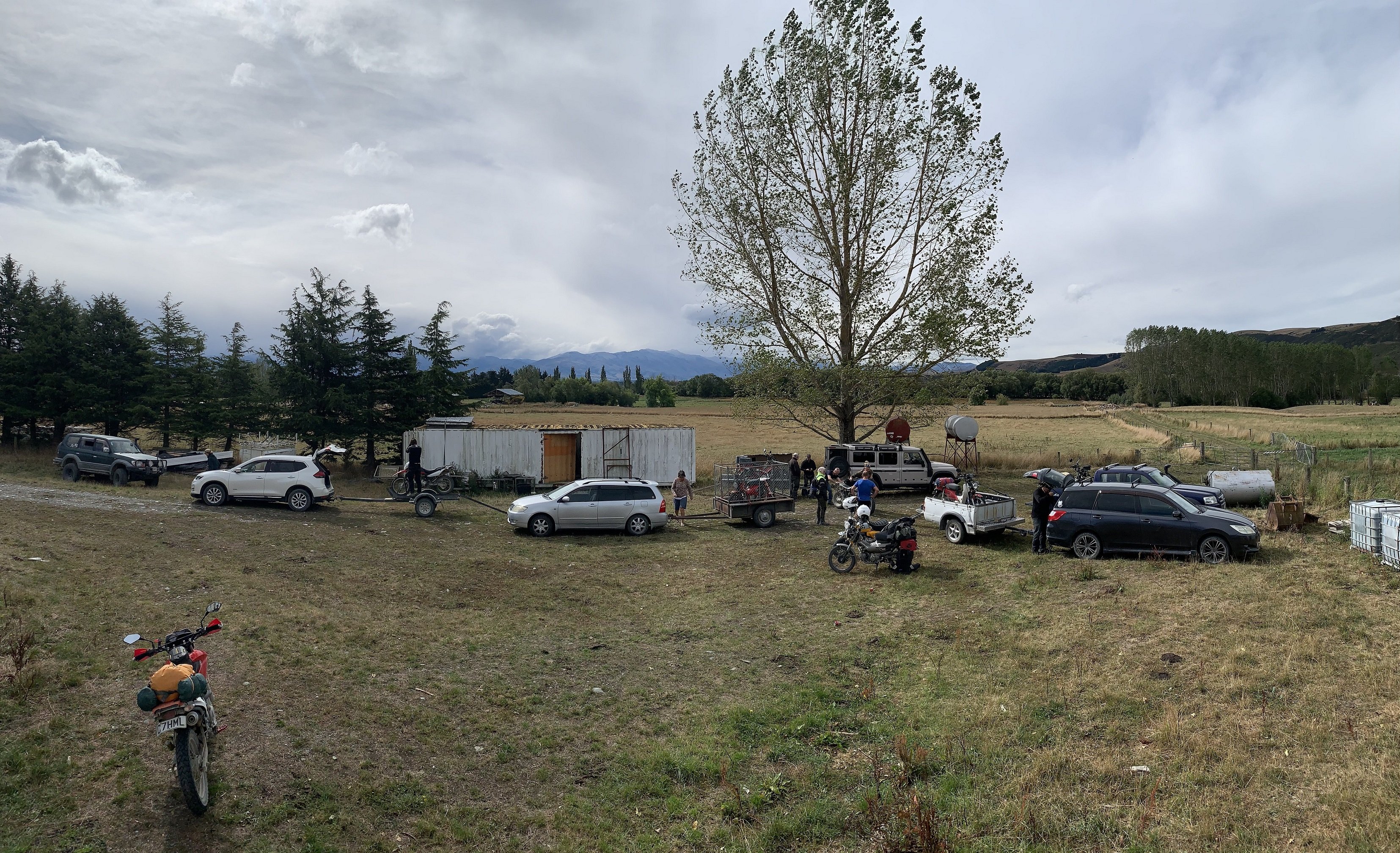
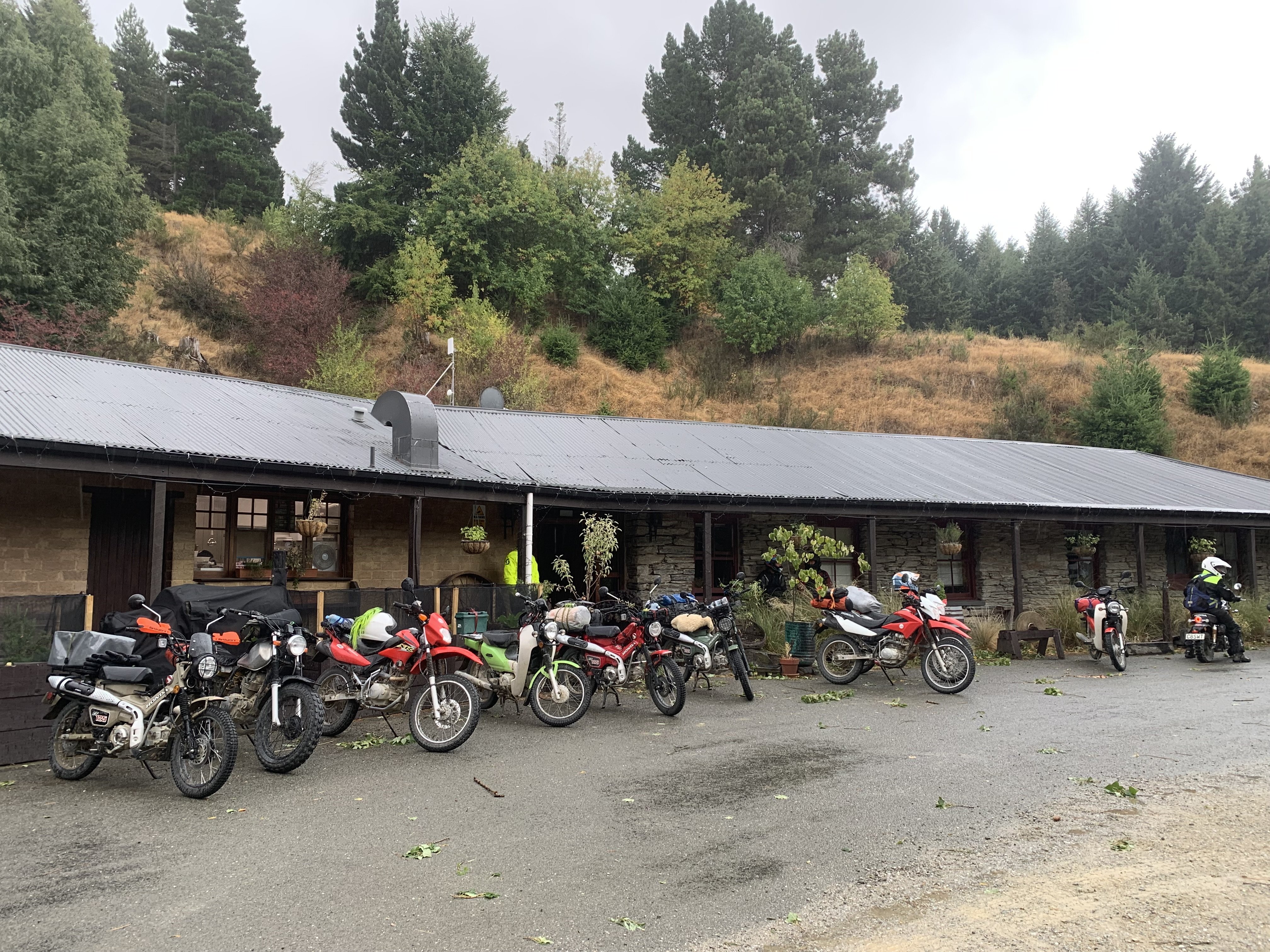
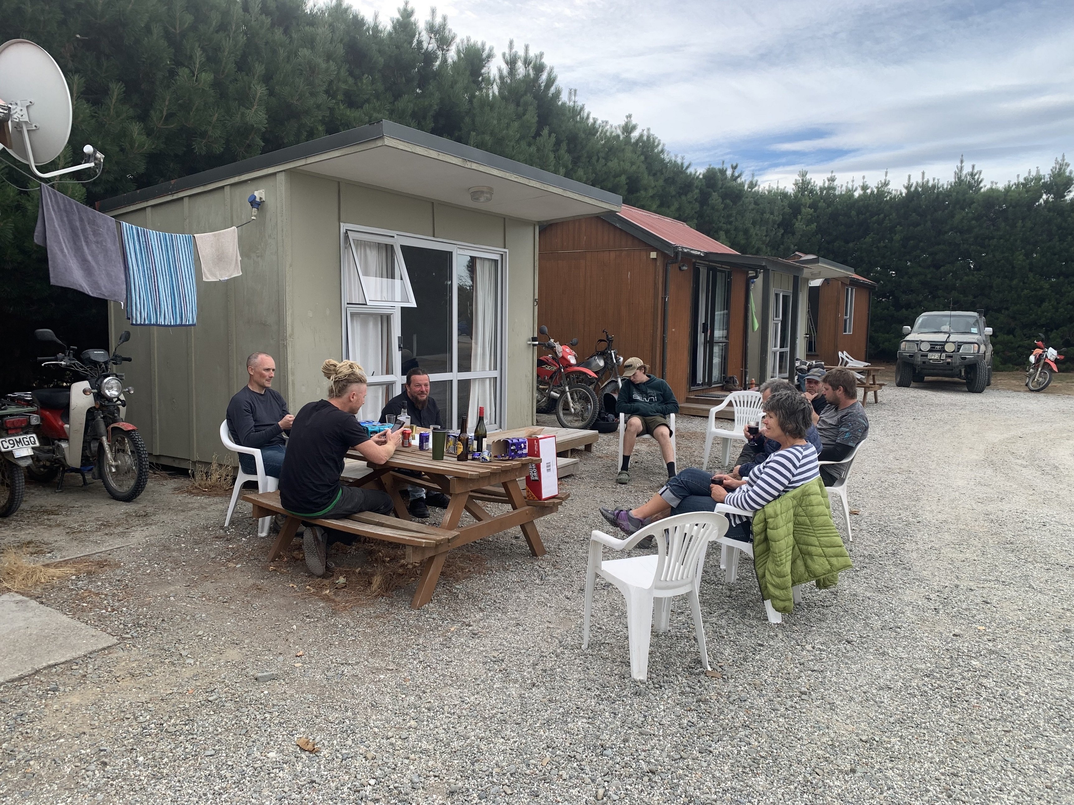
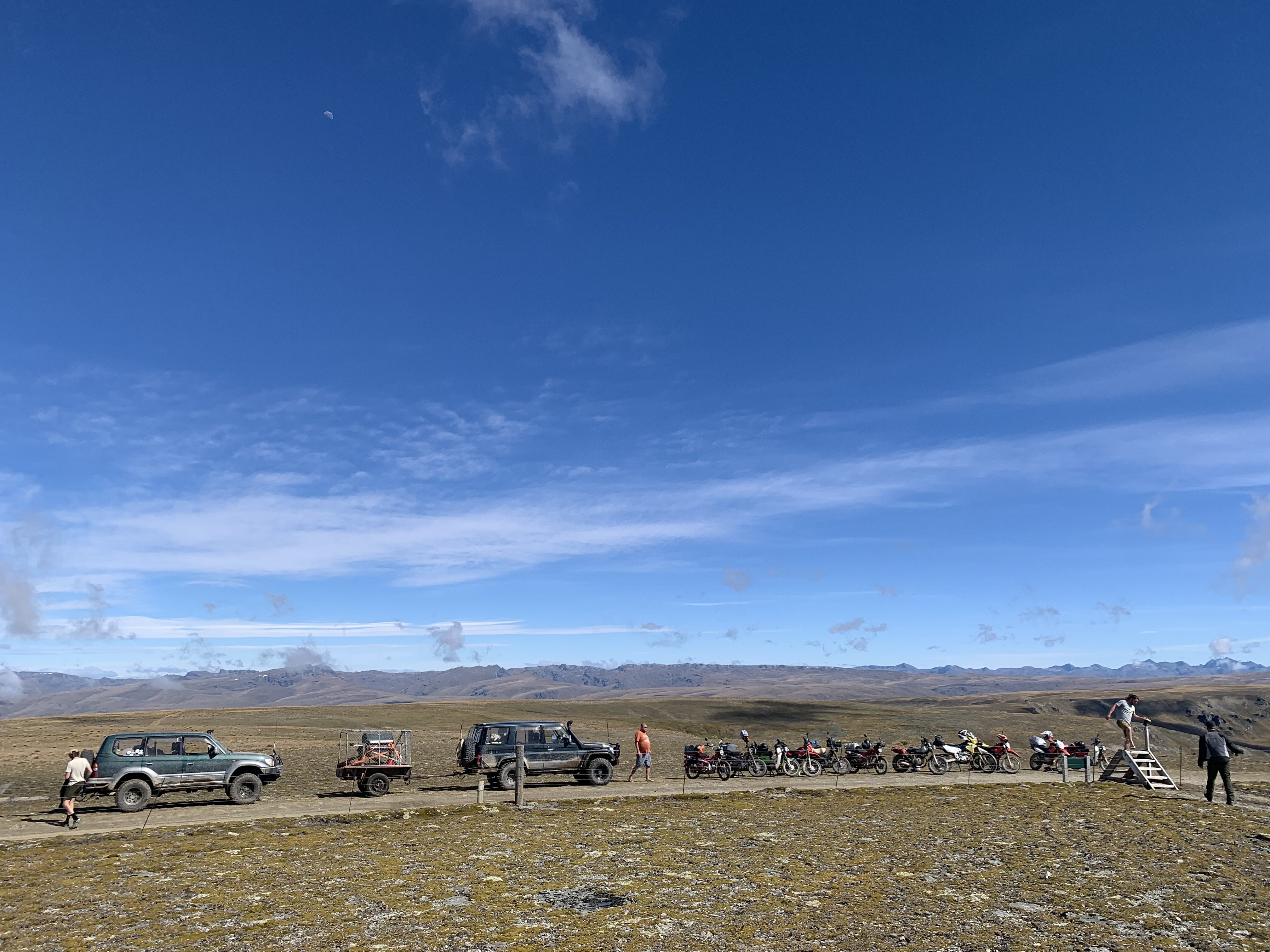
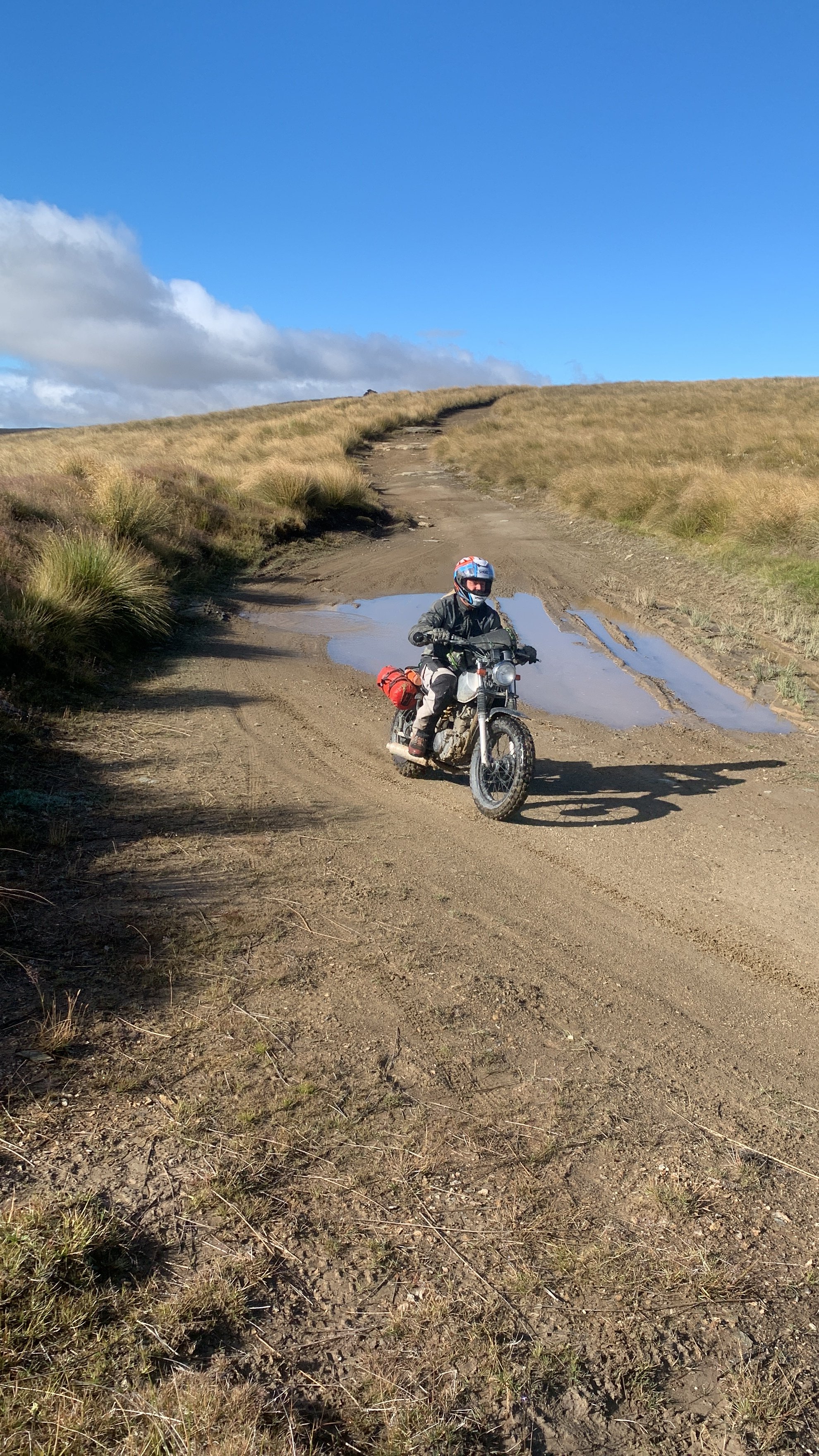
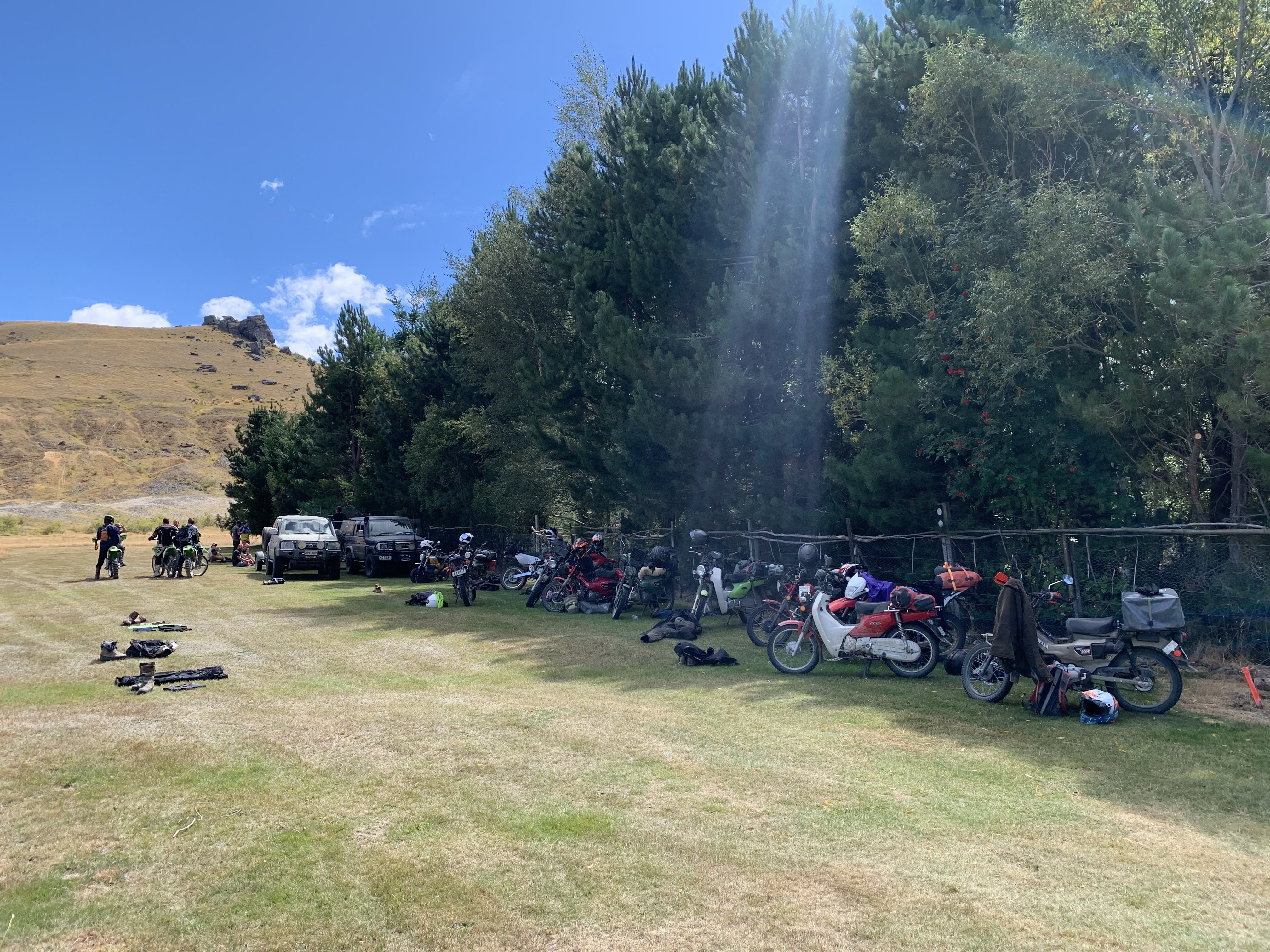
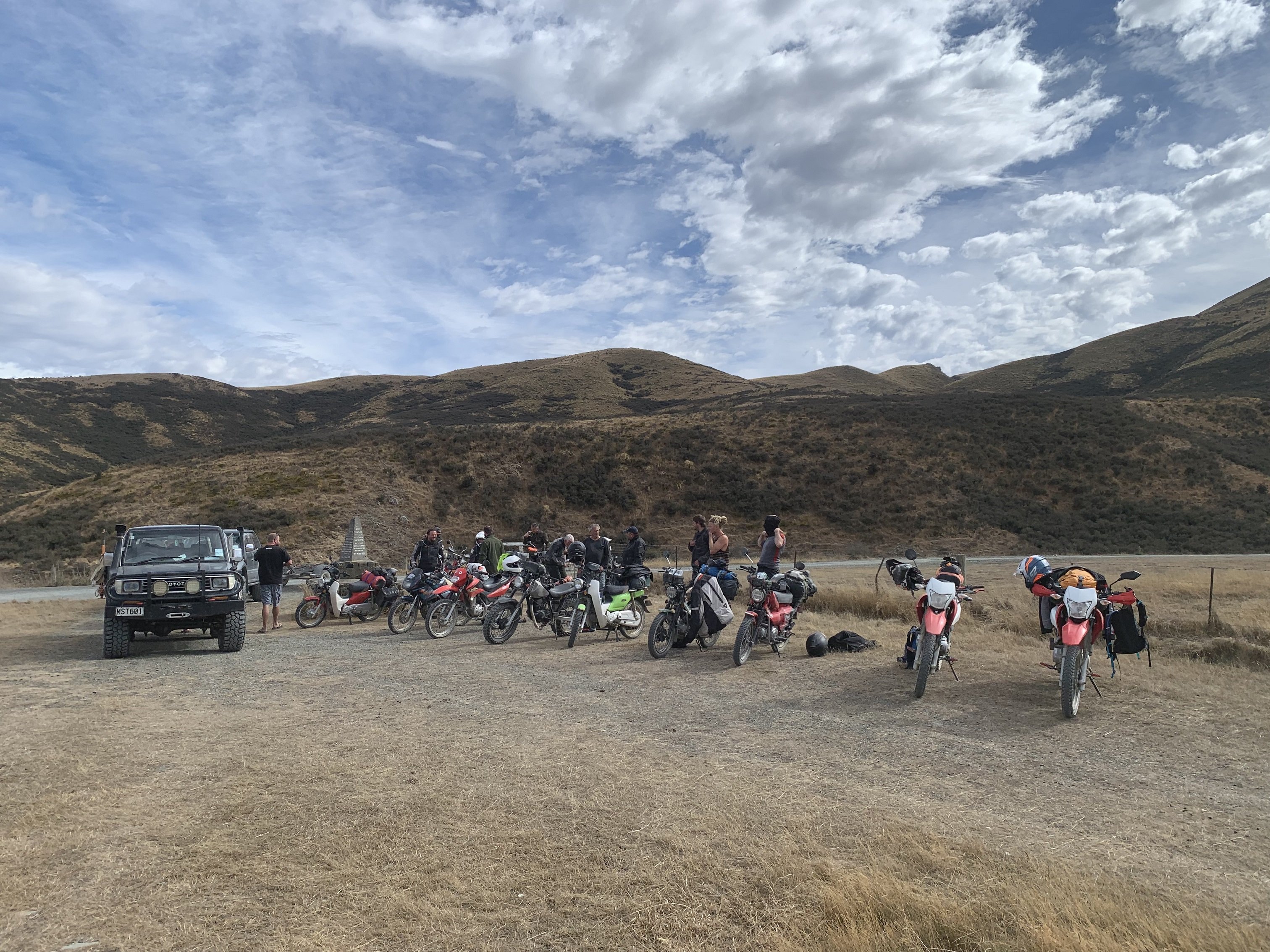
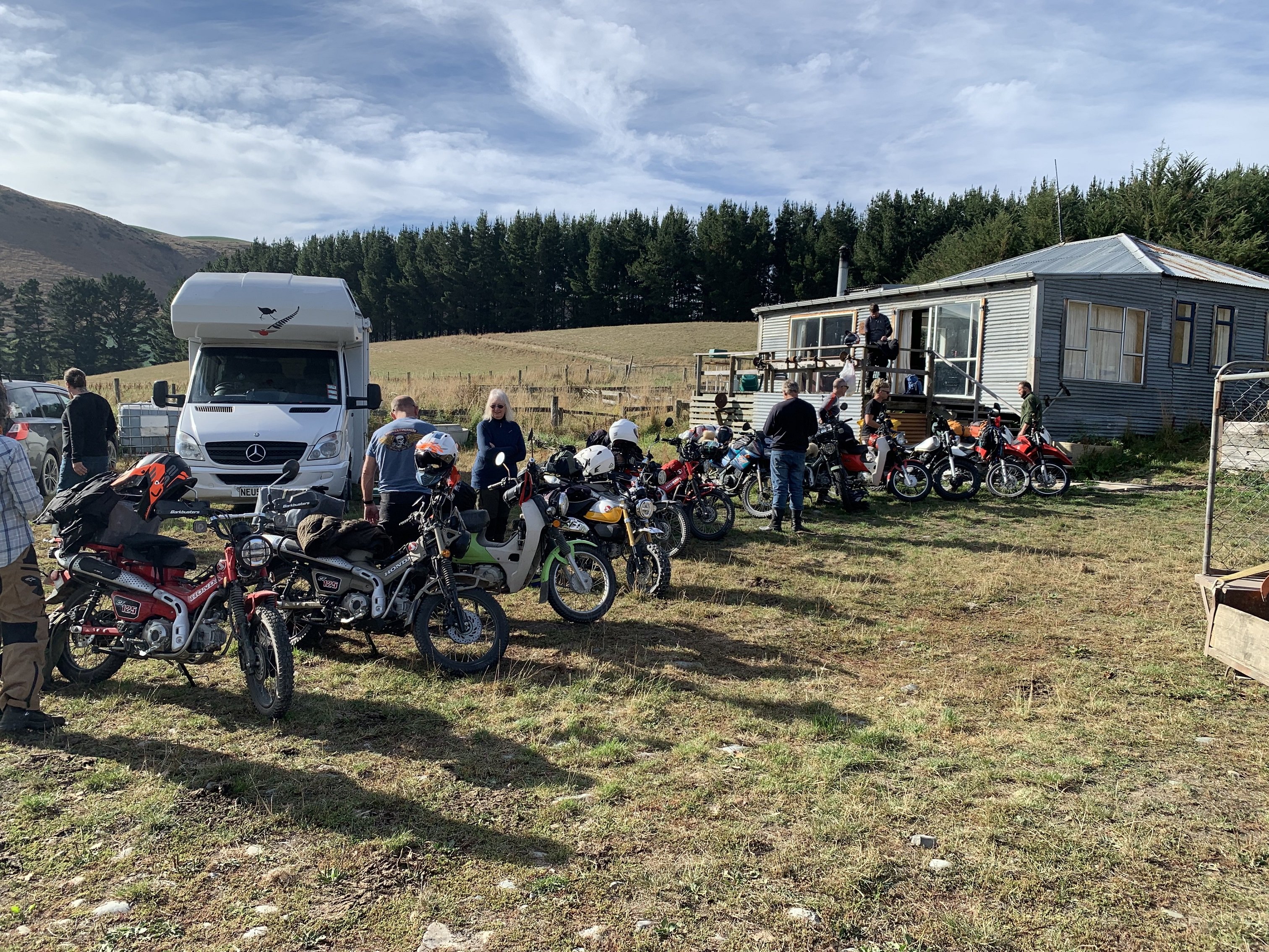
Bit of a pic dump. Thanks everyone who helped make this amazing journey possible. Such a good bunch of like minded adventurers, sharners and full senders, and I can't bloody wait for next year. I'll be sure to bring half a dozen spare tubes next year at the rate I was going!2 points
-
2 points
-
2 points
-
2 points
-
2 points
-
2 points
-
2 points
-
2 points
-
2 points
-
I spoke to the brother in law last night. Asked him about the fire ban in the region. (Hes in Alexandra, ex firefighter etc) He said the guy who runs that camp is a card carrying wombat/numpty/ejeet. And the fire ban does not include gas bbqs.2 points
-
Did a chunk of the back end wiring today, not much to see as I have tried to keep things tidy so it pretty much blends in. I tried to fit a new power plant, amazing that for the size this unit only makes one pogpower.2 points
-
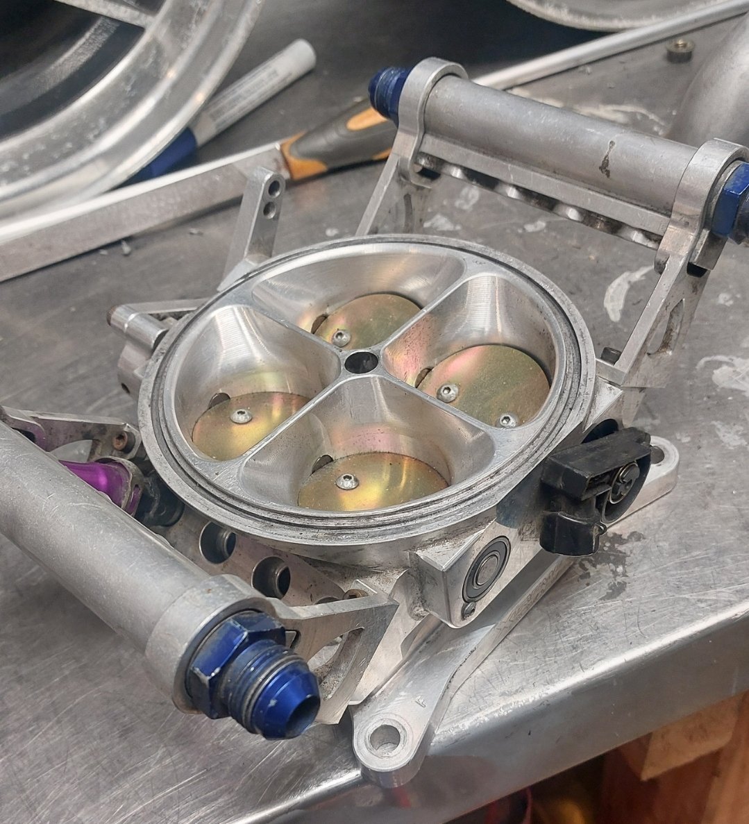
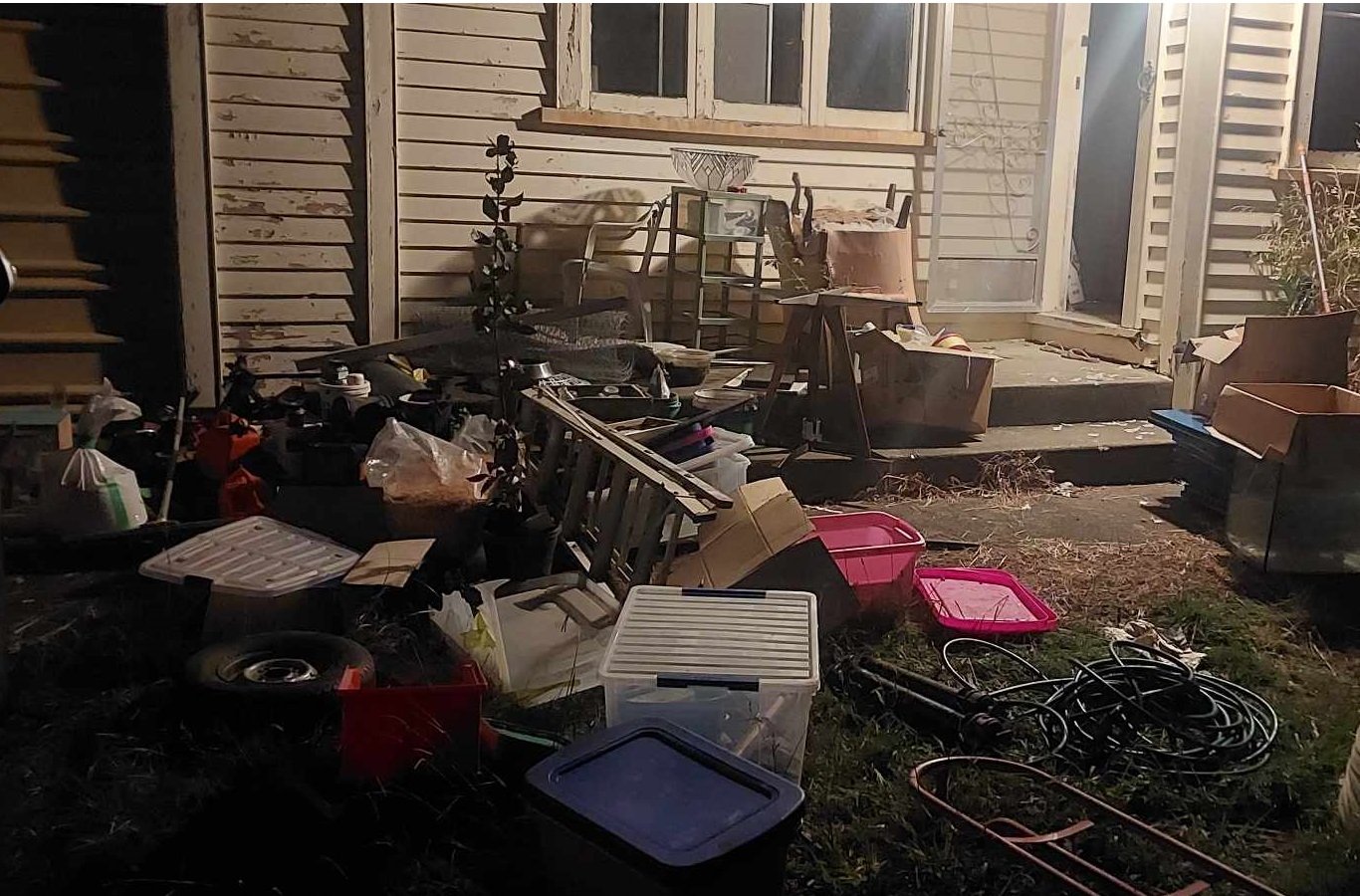
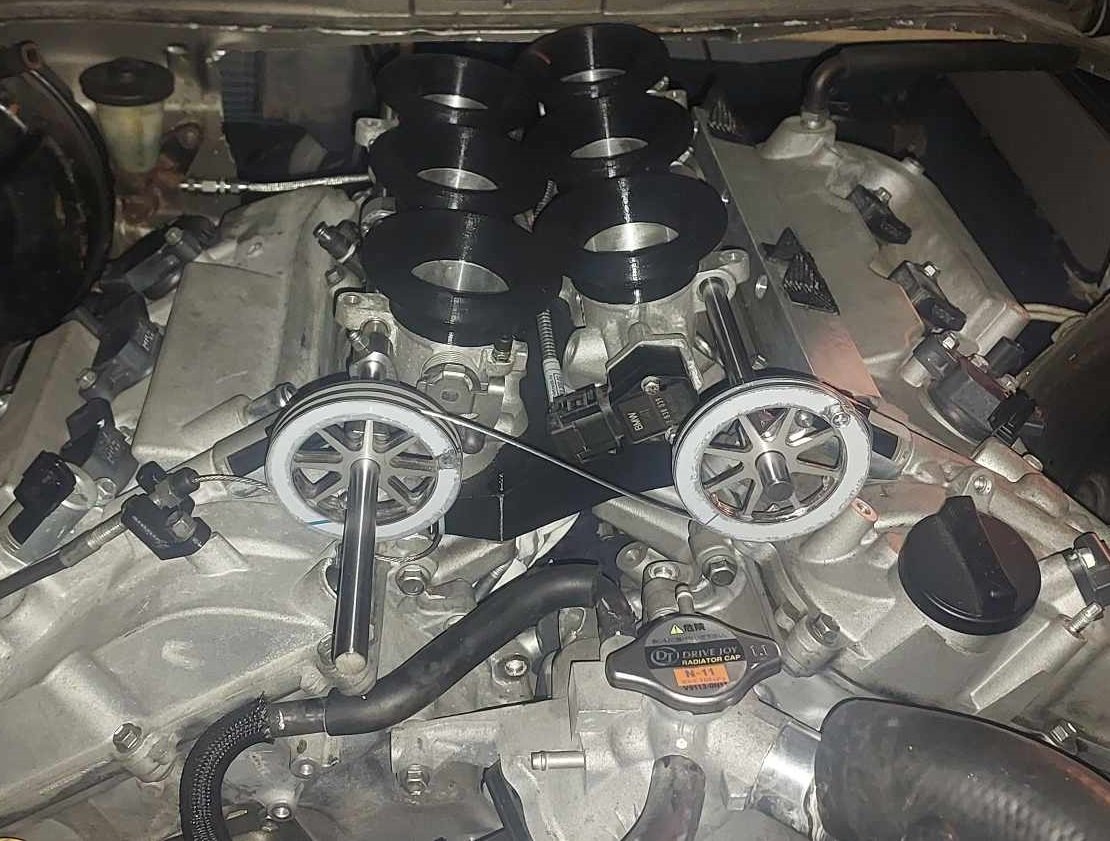
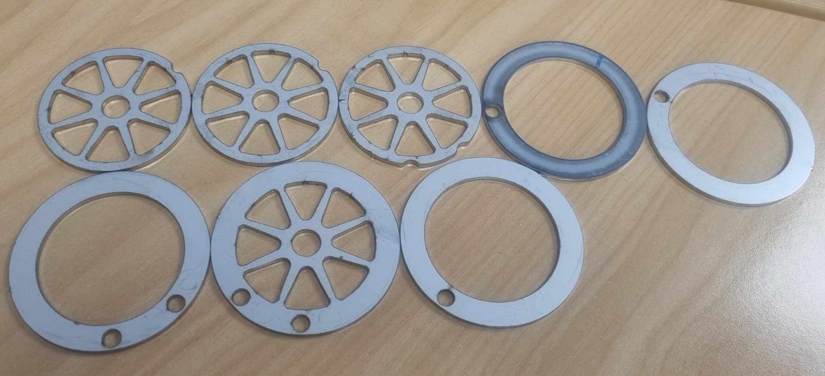
Alright so as of yesterday I'm finally out of mortgage prison! I finished moving house with heaps of time to spare, I definitely wasnt biffing trailer loads of stuff onto the lawn the night before settlement. I got some throttle pulleys cut from stainless. I'll put a radius on the inside of the pulley edges and deburr a few spots, but on the whole they came out really nicely. Quite heavy though, probably could have made some parts thinner. (Everything 2mm stainless) It's looking like it'll be fiddlier than expected to balance the cable length and pulley positions to get the banks even. One thing that I didnt take into account is that there is no tolerance for having a cable that is "overlength" as you physically cant slide the protruding end of the cable into the pulley. However I could probably chop out the relevant section of the pulley to allow this without any issues, as these are still significantly beefier than they need to be. I need to make some end stops of some sort to stop the throttle rails moving forward or backwards so everything stays aligned correctly. You may notice that in this photo I've got the linking cable on the wrong way up. It looks dumb having these on the front of the motor, but down the back is getting very crowded and I've got ants in my pants to get this damn thing fired up. I got the throttle rails drilled, took about 3 hours to drill 6 holes! We had to grind flats onto the rod to get through the hardening. Otherwise carbide bits didnt even make a dent. Next jobs are to print a final iteration of the manifold from Nylon, get fuel lines connected up, and keep working on the exhaust. Then I'm preeeeety close to firing it up!
2 points
-
Try lee at diffs r us. Has moved from otahuhu to pukekawa now. Old man used him a couple of weeks back.1 point
-
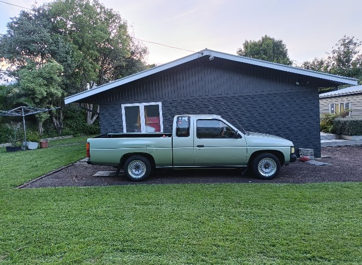
Reset springs in. It's not actually low but it sites level now now and looks a lot better. New shocks are on the list, these don't have any shock left in them.
1 point
-
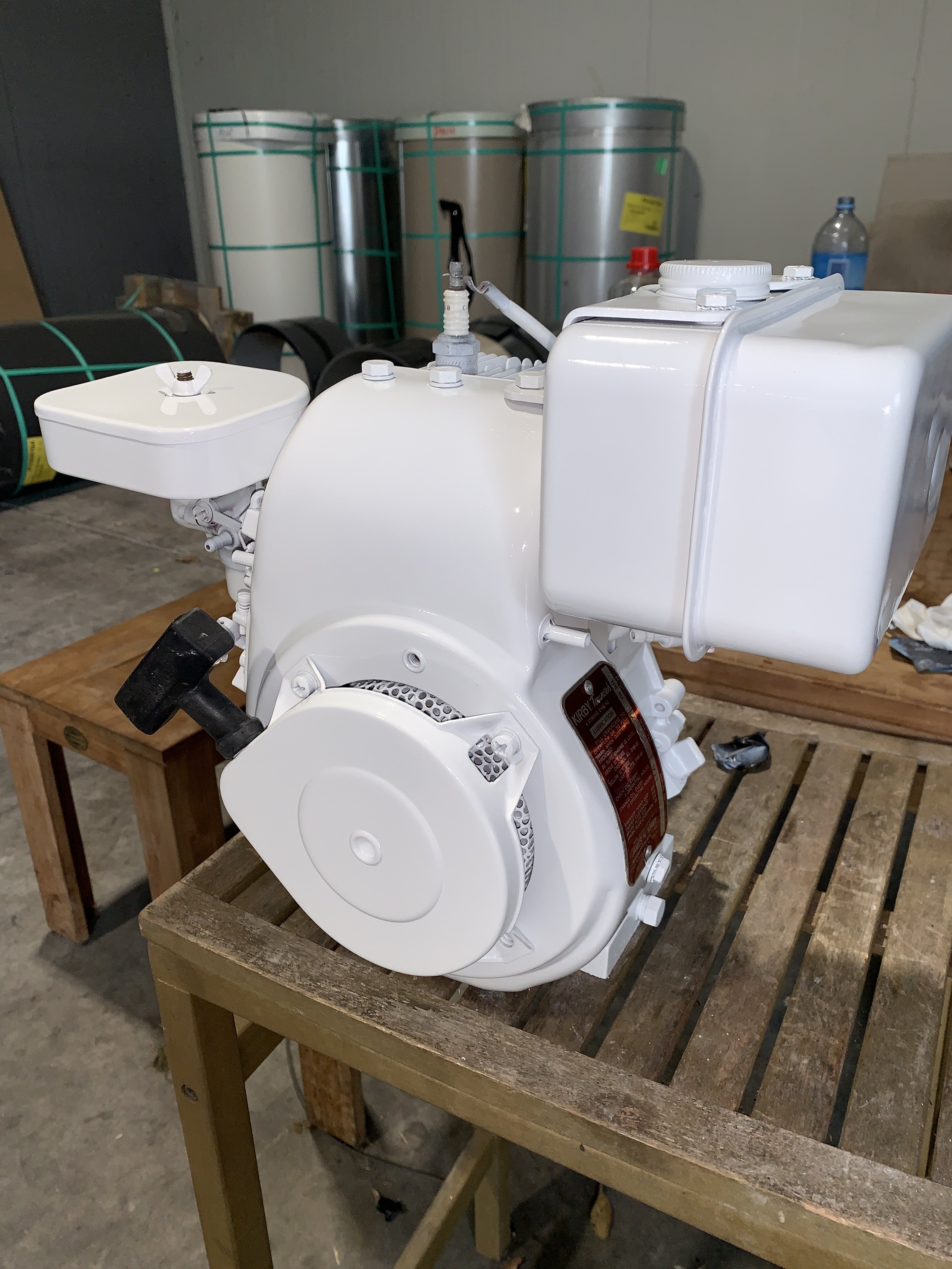
It’s been a while but I’m slowly chipping away at the bike, My work has been rather quiet and on my breaks I prepped and finally painted the engine. It was painted using a can of Mipa 2K aerosol can white over some rustoleum general white primer and has come out absolutely stunning and will fit the bike incredibly well, I also managed to paint both mudguards and the chain guard using this one can and I’m incredibly satisfied with the result although there are a few flaws just from improper prep work. Overall I’m really happy with how it all turned out and the 2k paint should hold up well for any potential fuel spills. The original engine was dated to be a 1976 Kirby Tec so I’m gonna assume the bike was produced on this year so she’s a 1976
1 point
-
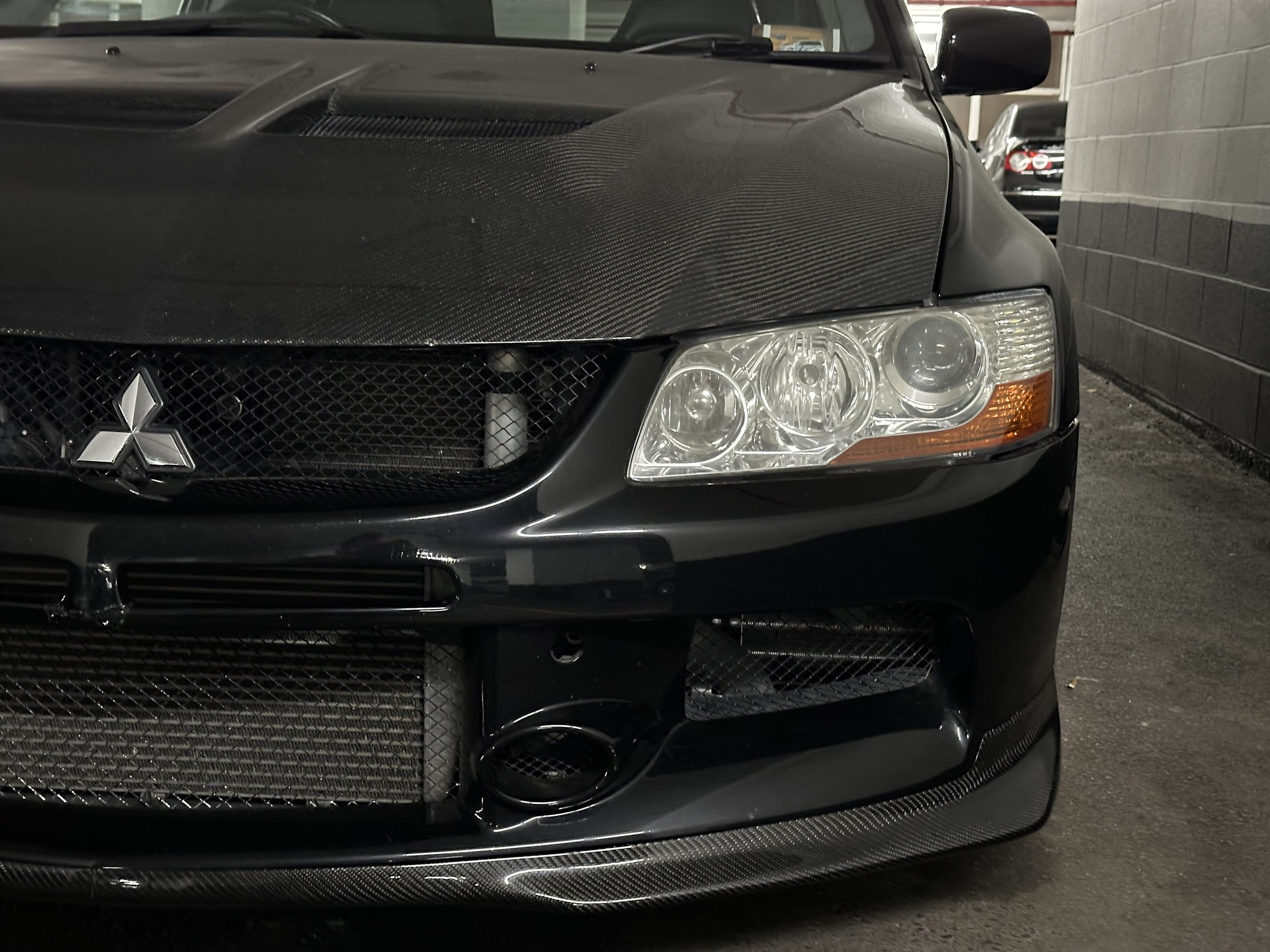
Finally got around to fitting the Ralliart CF front lip. I ended up cutting it in half in order to transport it from NZ to Canada so will tidy up the join properly in time, but for now it's hardly noticeable. I'm going to place a Ralliart sticker over top of the join anyway to hide it further
1 point
-
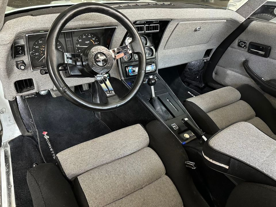
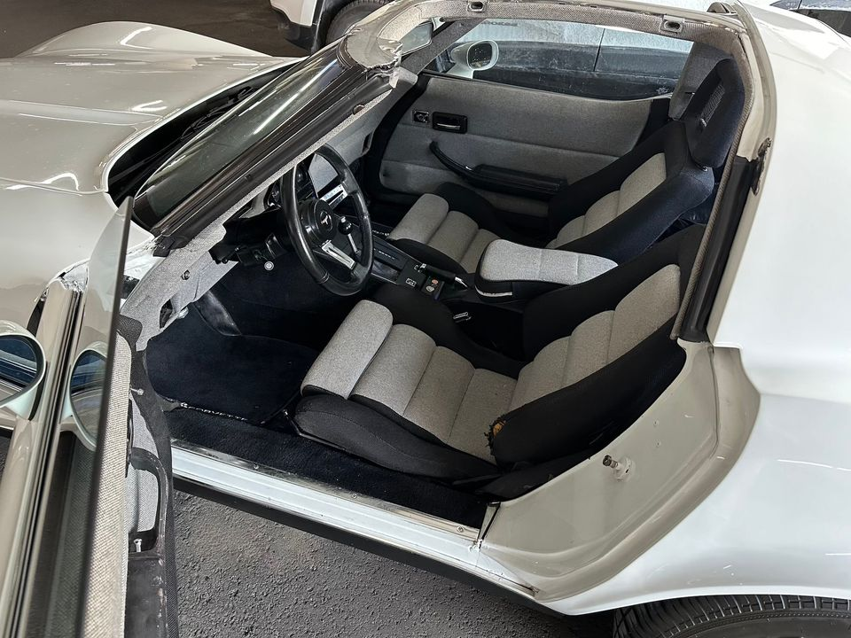
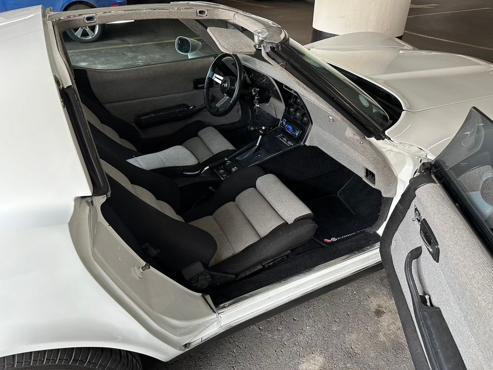
Added LED lamps to the interior and put in some new floor mats to help tidy up a bit of the roughness: Disco fred here -
1 point
-
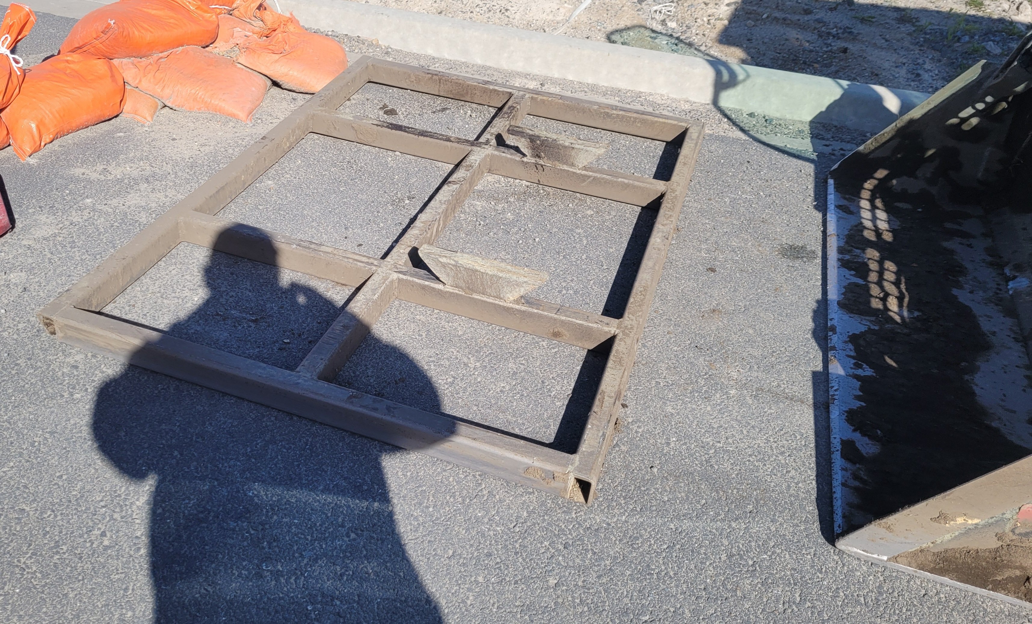
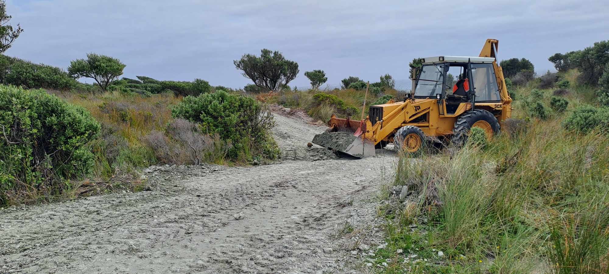
That looks like a 4in 1 bucket on the job. I'd recommend whipping up one of these. Leveling bar you just grab with the bucket.
1 point
-
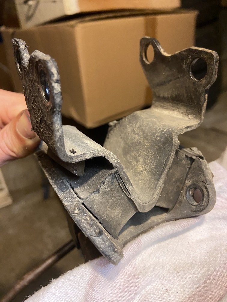
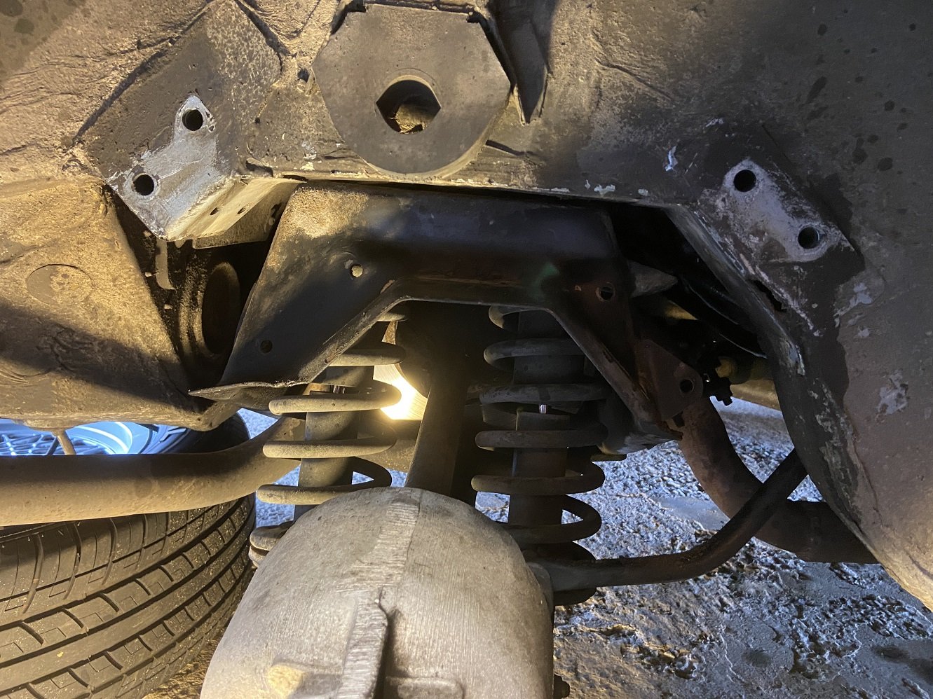
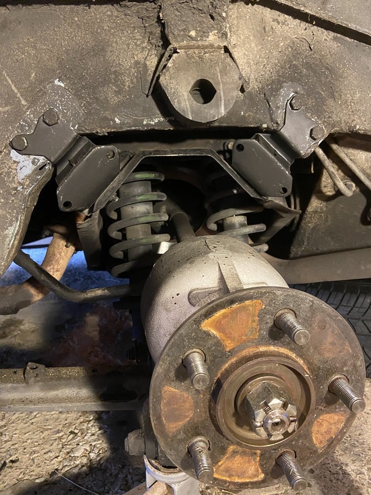
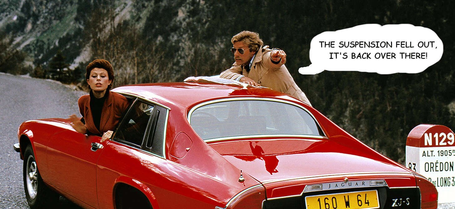
Boring update: I finally changed the rear subframe mounts. Here's the one I had been most concerned about. I had expected to find it in worse shape once it was off the car. Hardly worth worrying about really. This rubber-to-metal bond is the only thing that seems to keep the IRS assembly attached to the car. There is a radius arm connected near each rear hub which twists the whole IRS assembly in its mounts as the car leans in the corners, creating a passive rear wheel steering drunken snake effect. Wikipedia says this "...may result in significantly improved handling". May? Anyway, the mounts can fail from age or too many burnouts, and then you definitely won't have significantly improved handling. In this shot, the two subframe mounts have been removed: You can see the IRS cage thing, the tricky double shocks and springs, the light reflecting off the inboard rear brake disc, the skinny anti-roll bar terminating at the base of the RH spring (not present on all XJSs).... You can also see that I managed to change the mounts without disconnecting anything such as the exhaust, brake lines, roll bar, driveshaft, radius arm etc. I did one side of the car at a time, using a jack and an axle stand. New mounts fitted (this is on the opposite side of the car, to mess with your head): Now that these mounts are done, I'm not gonna be THAT guy:
1 point
-
Is that KFC in front of the JCB?1 point
-
I spent most of the weekend carting schist and extending the driveway. The JCB is finally operational but oh lord it's slow and noisy. Still much better than a spade and a wheelbarrow
1 point
-
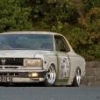
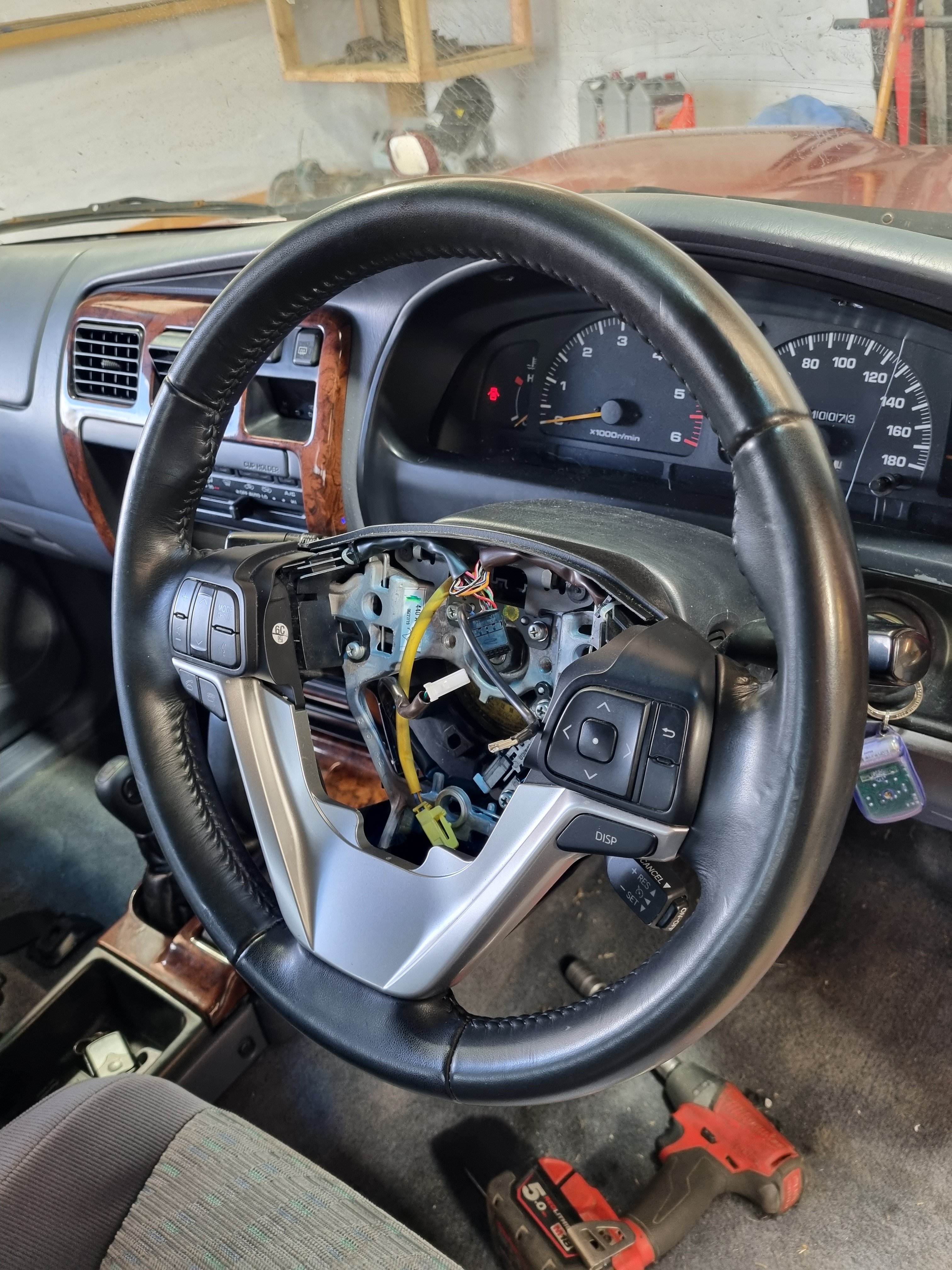
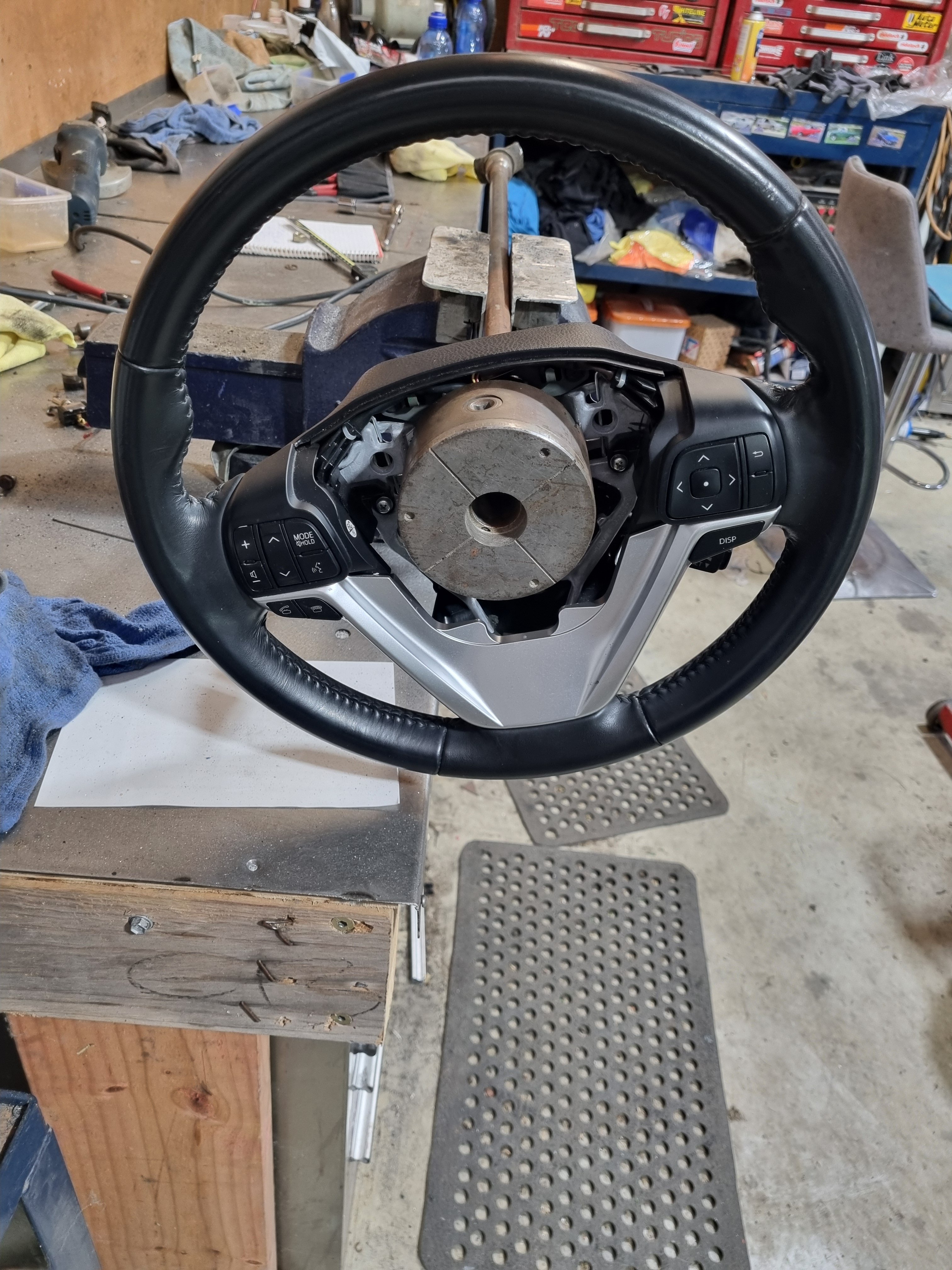
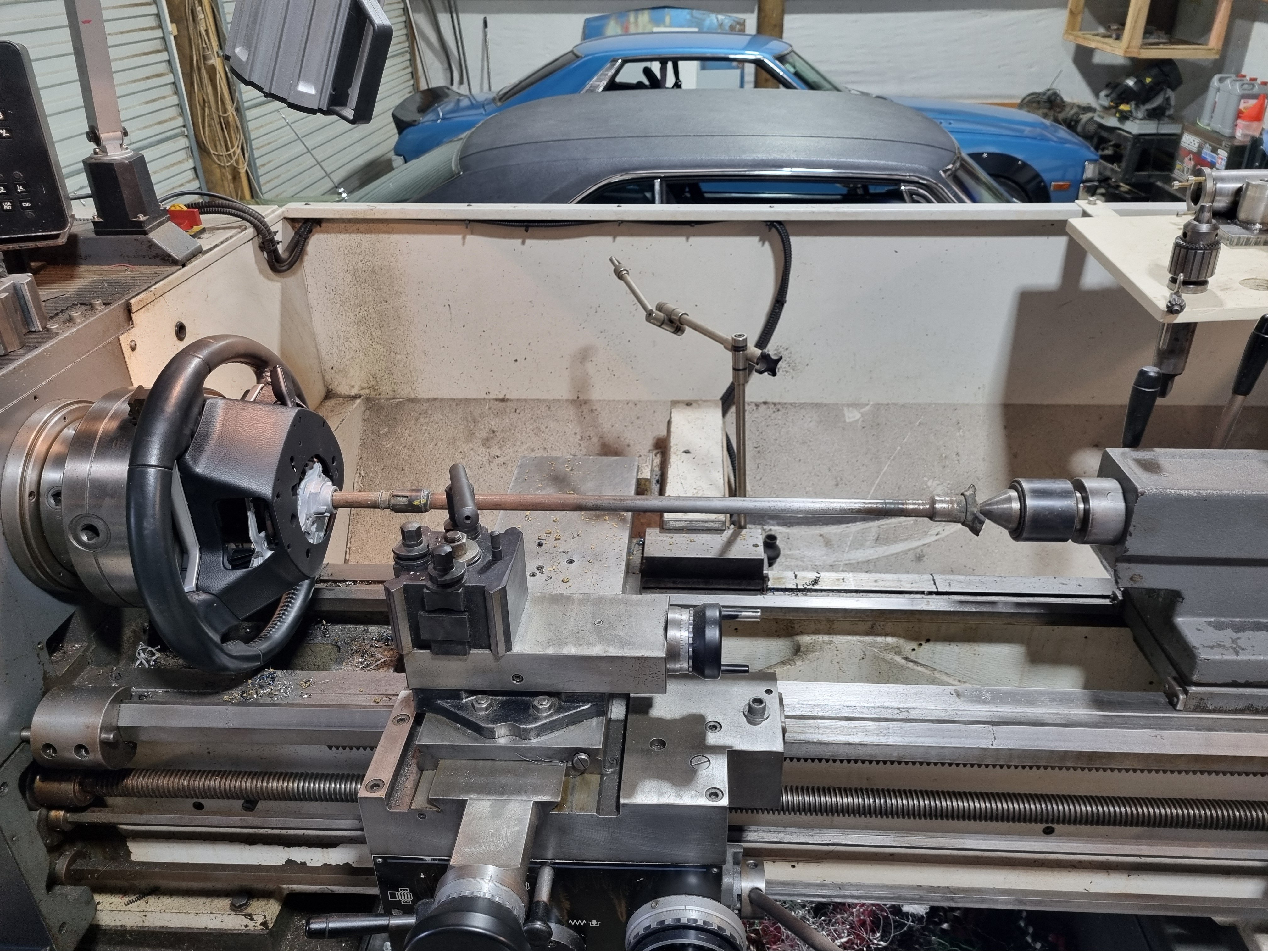
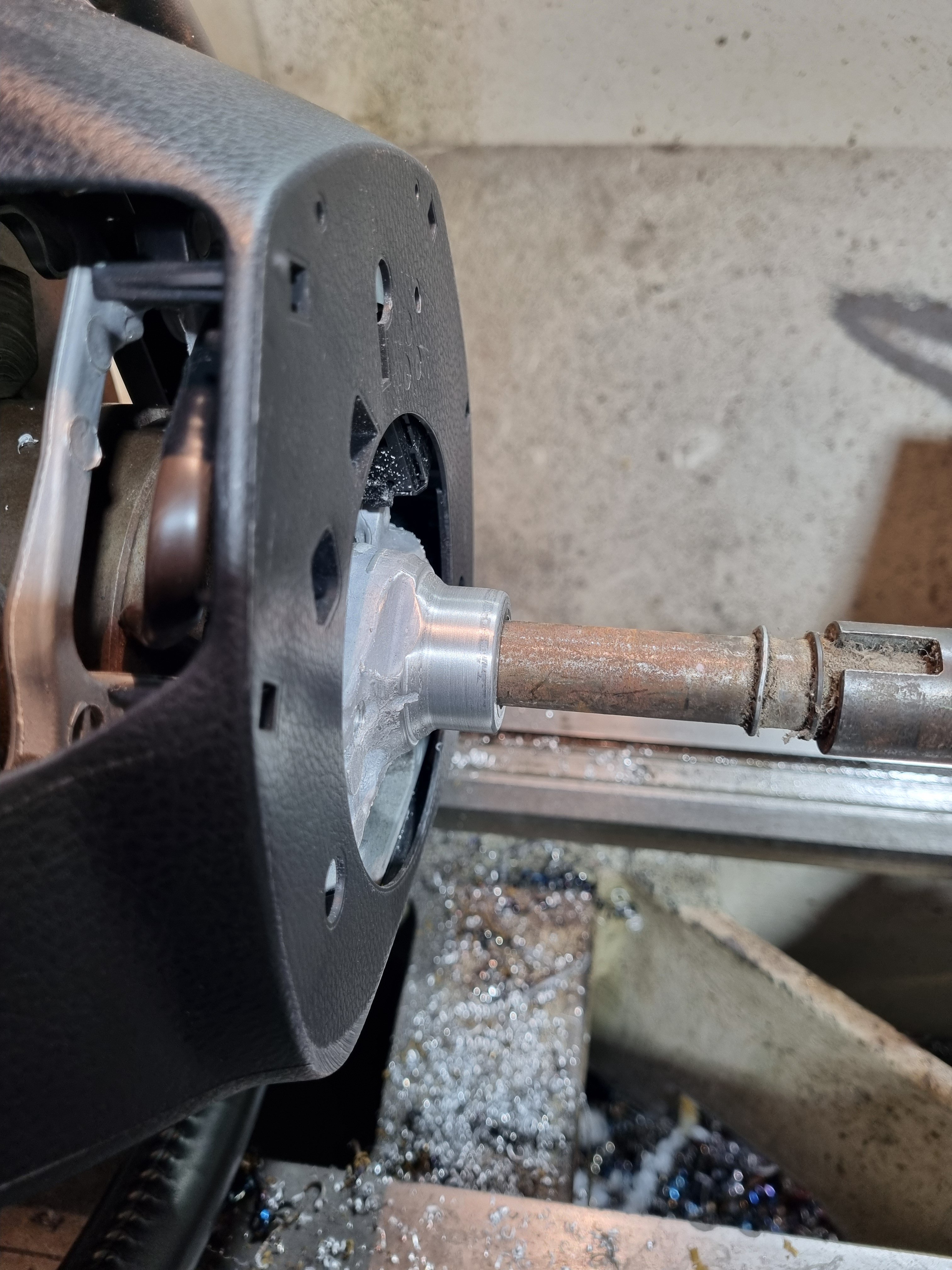
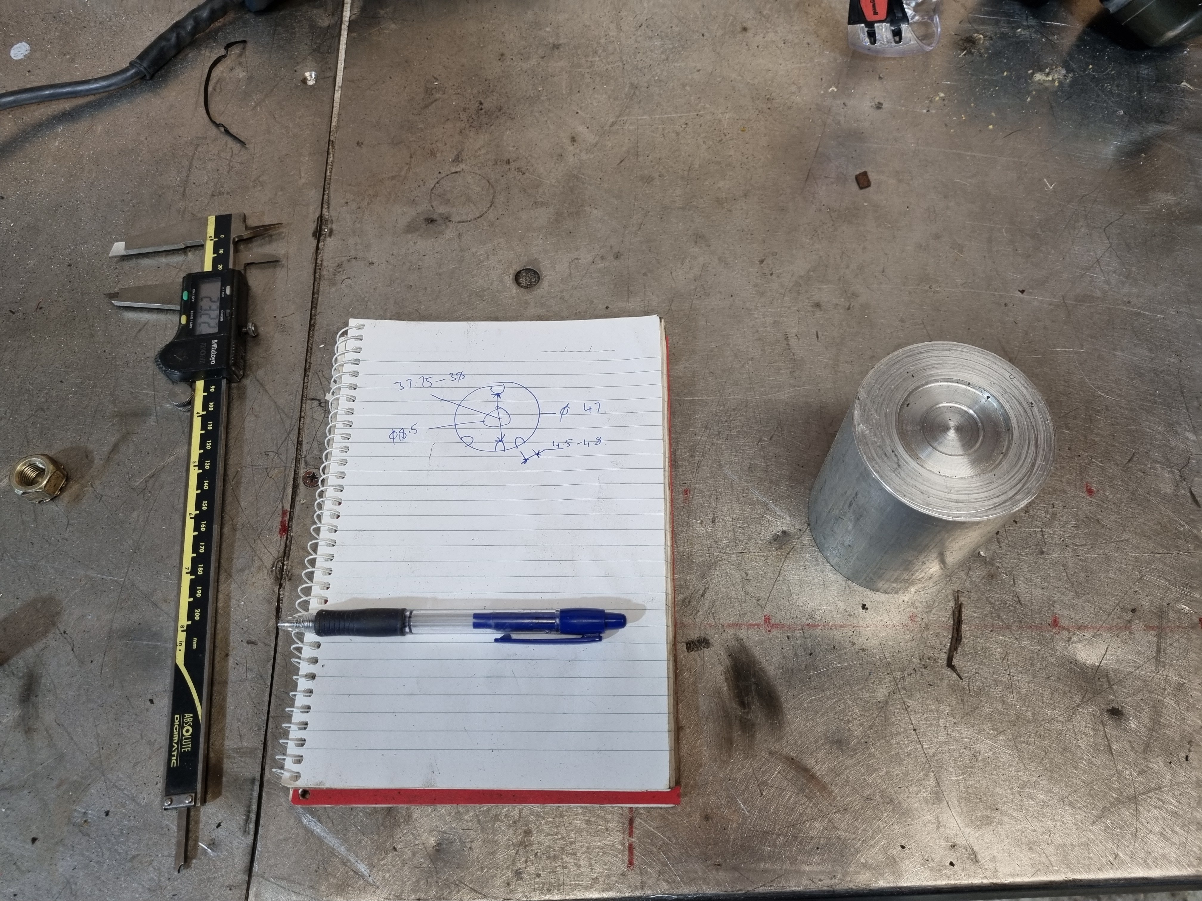
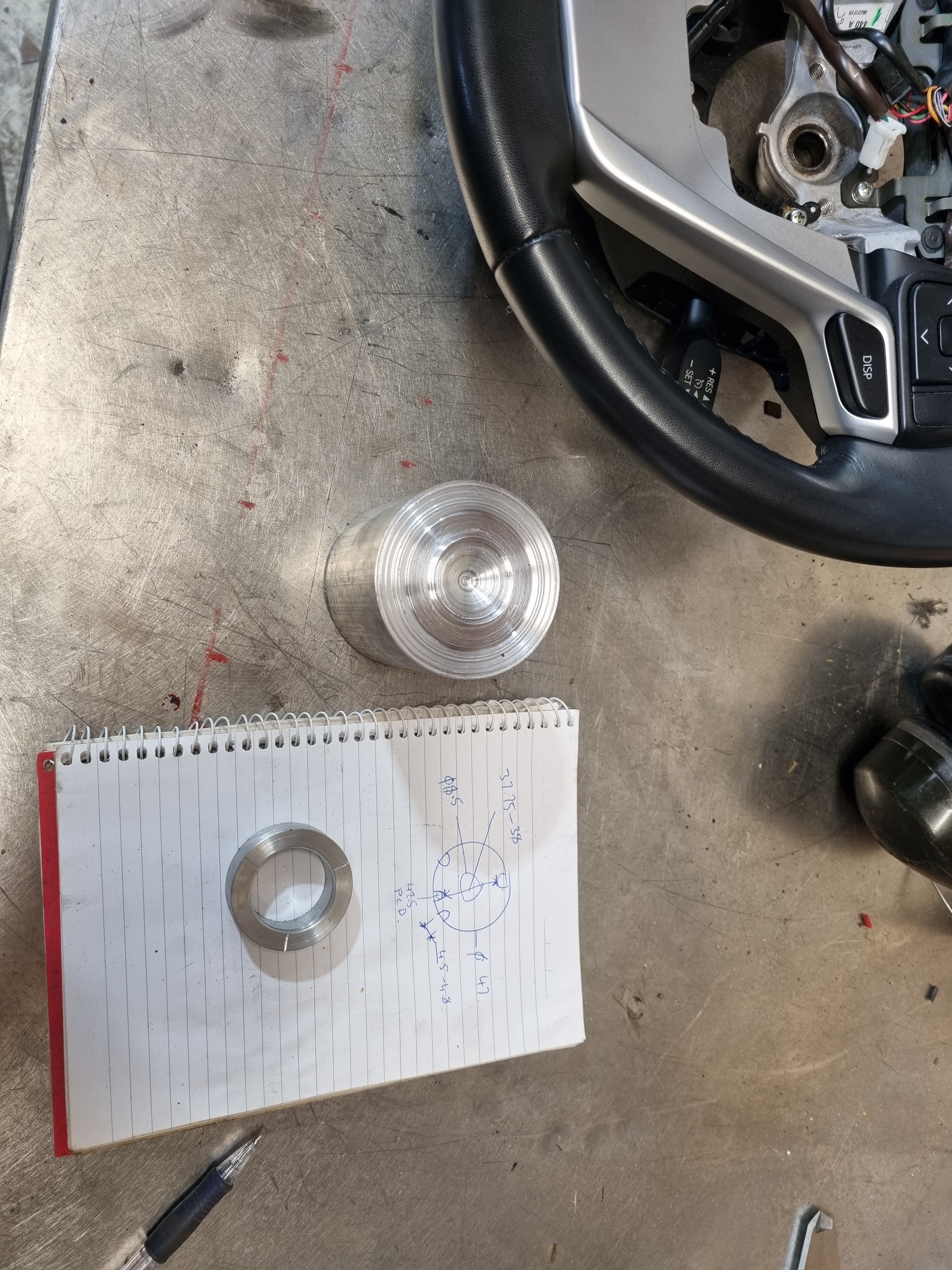
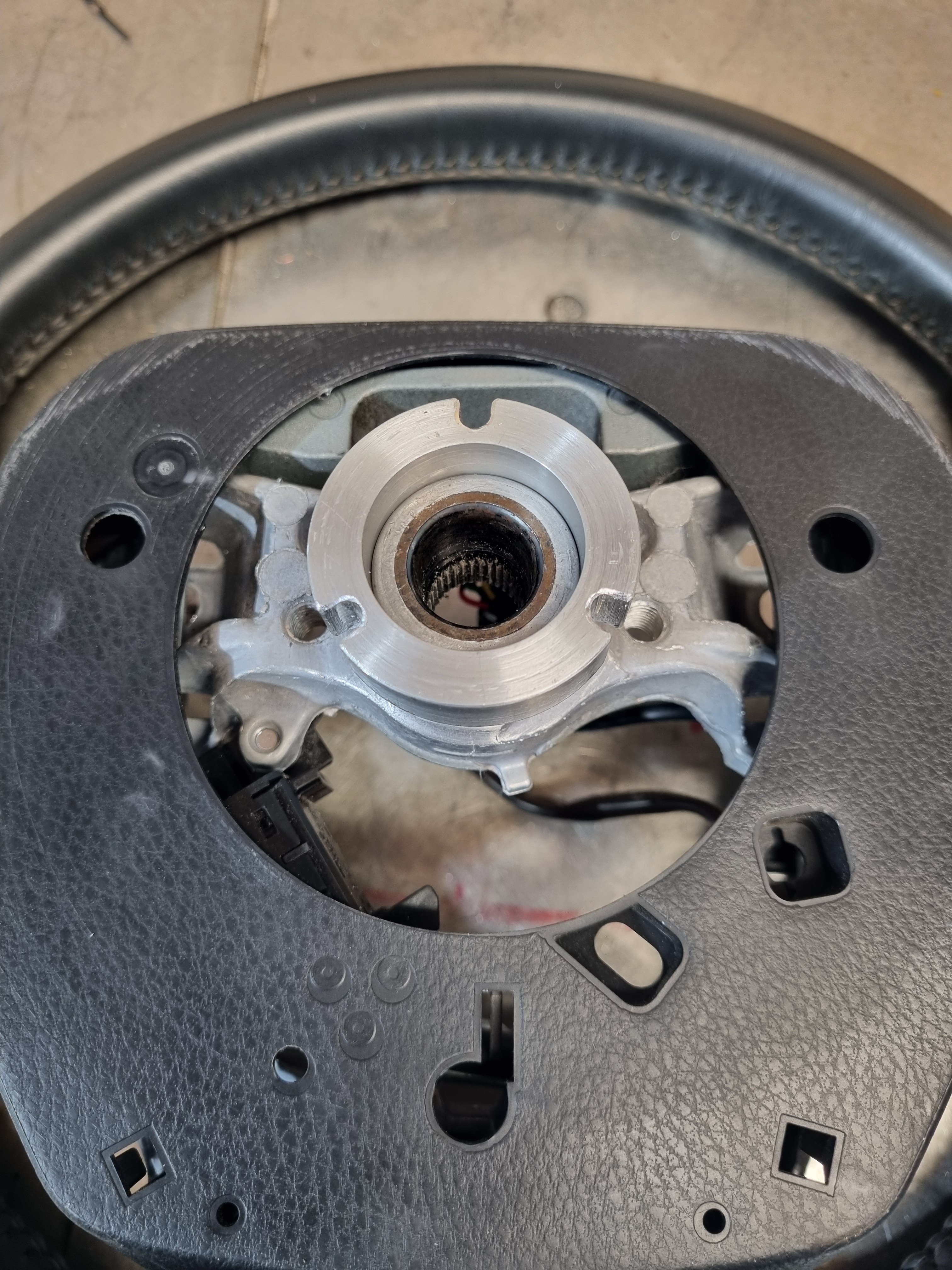
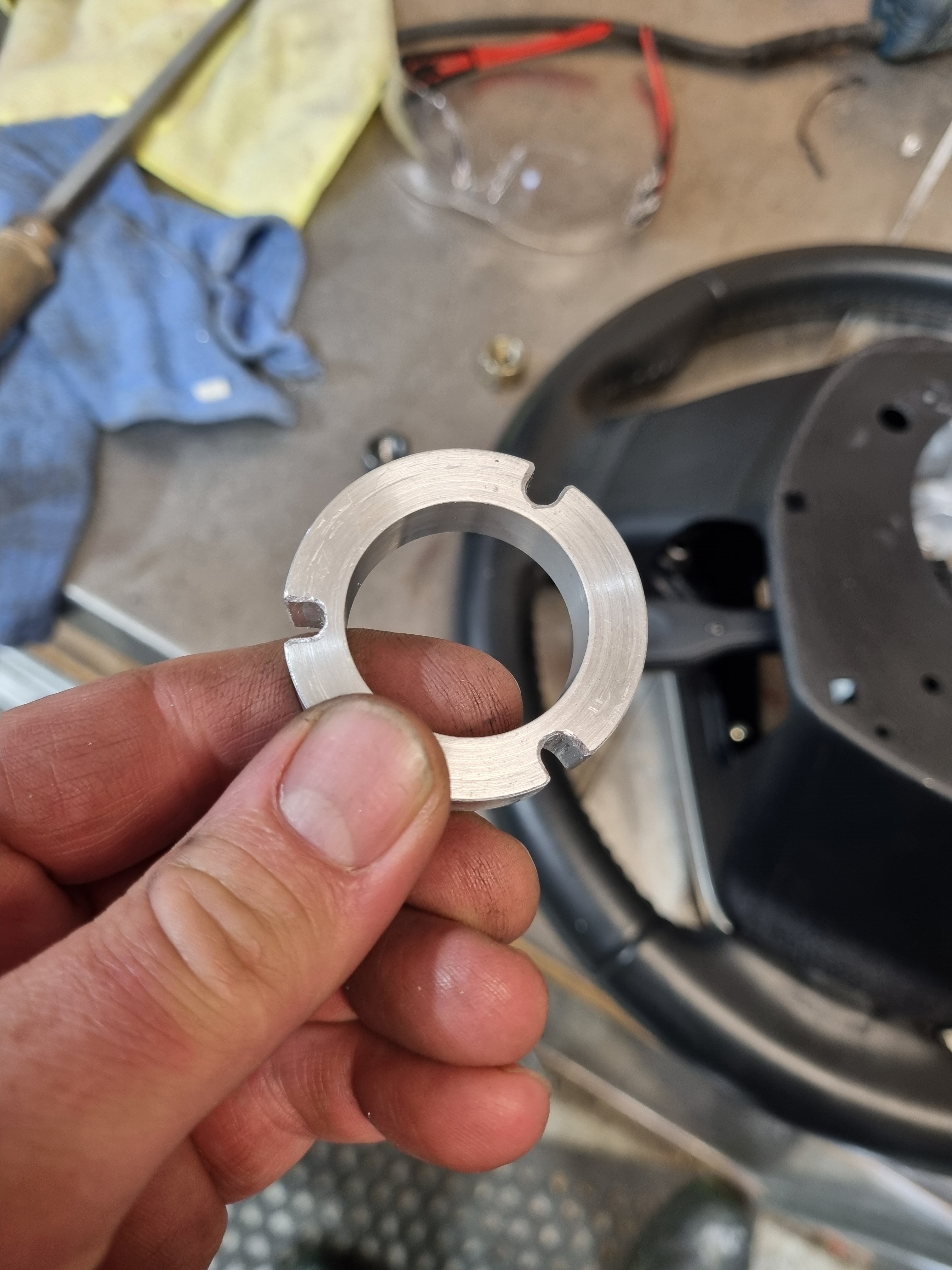
Story time/ going down the rabbit hole. The issue- I never did any homework at all when it came to buying this blaupunkt head unit. If I had of I would have very quickly been made aware of how crap it is. Is unusable as far as changing the volume, shipping tracks or doing anything. Its physically impossible to change the volume accurately, and most of the time is not possible at all. Totally my fault for not checking a single review or anything. So, present day me (well yesterday me actually) was yarning to Nick the sparky about steering wheel controls and clock springs and whatnot and he said "I've got a 2013 Highlander steering wheel, see it that fits" It does. I needed to make a indicator canceling wheel to adapt the new wheel to the hilux. Not super difficult, made a frankinstien rig up to machine a parallel diameter in the back of the wheel. Them made a ring that I will shrink onto the back of the wheel once I confirm its fits the truck. Then the next hurdle will be getting signals through the clock spring. It has 3 spare wires that aren't used so we can use those to send signals to the head unit. But there are probably other clock springs that will fit the truck that have more wires if we need it.
1 point
-
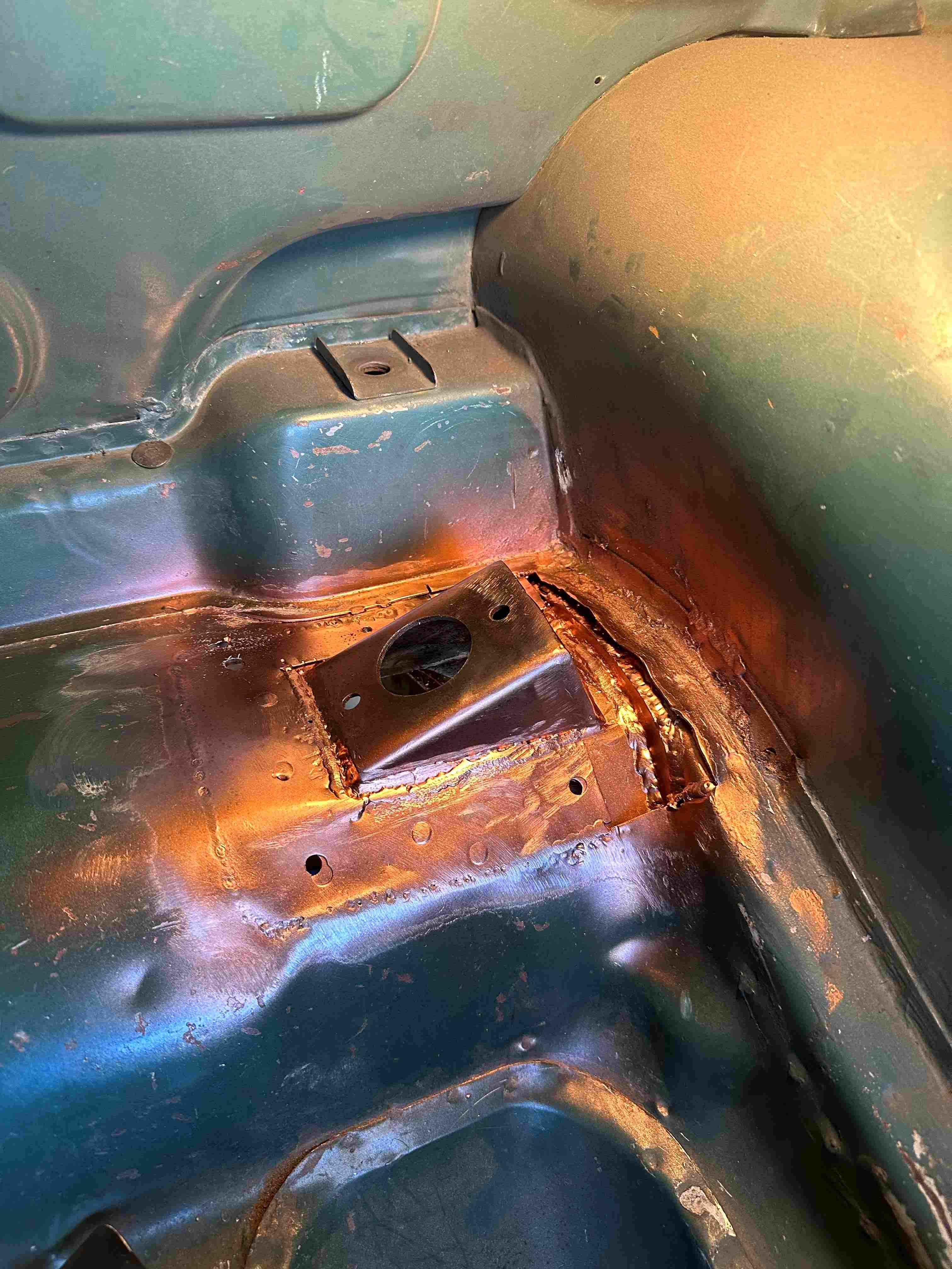
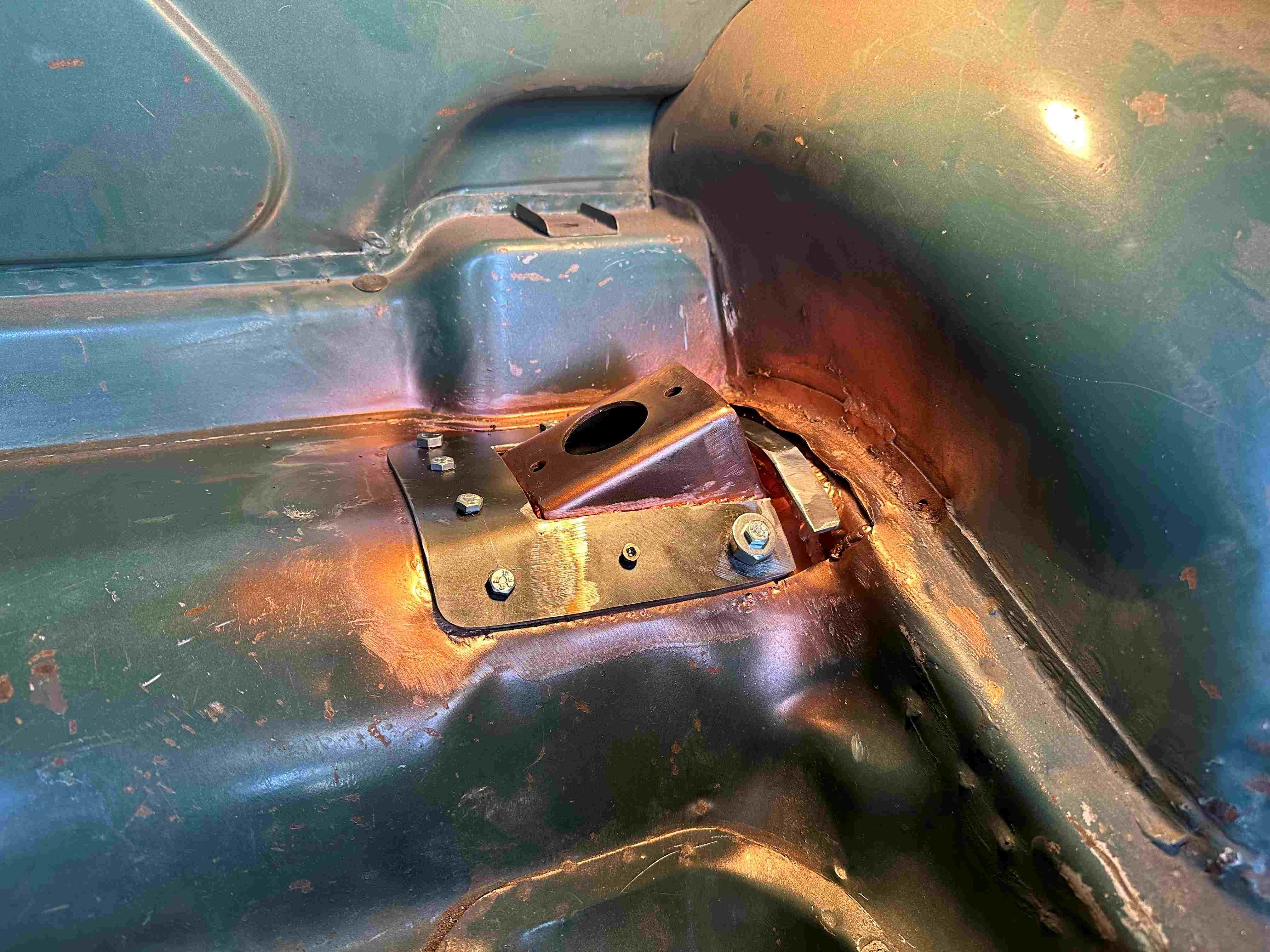
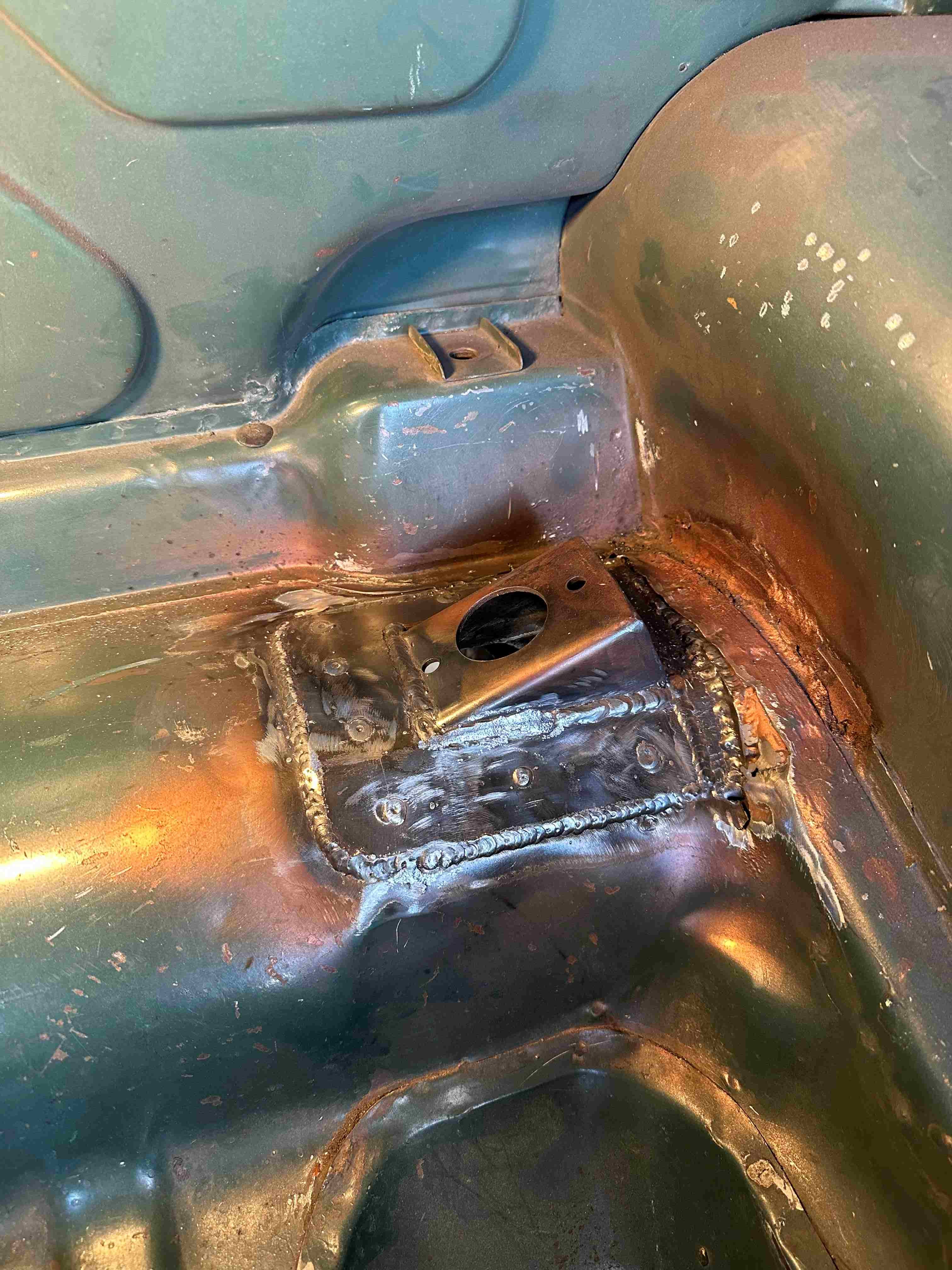
I managed to get the driver side welded in. Man, that took some time. By the time I clamped it in place (the easy bit) then put the 4 bolts in to hold it to the boots sheet metal. Then used some metal screws in between the bolts to hold the sheet metal to the shock mount. Then welded the bracket to the boot floor and the chassis fish plate. Once that was welded in I had to fit and weld the top plate which sandwiches the boot floor between the two. I made the top plate a little smaller in size so when I welded it, I was welding to the weld and bottom plate so I could use a bit more heat. Same procedure with bolts and screws and then welded it in. Welding went well really (well I think), though not that easy being folded in two inside the boot for some of it. Should have taken the pic before I sprayed on the weld through.
1 point
-
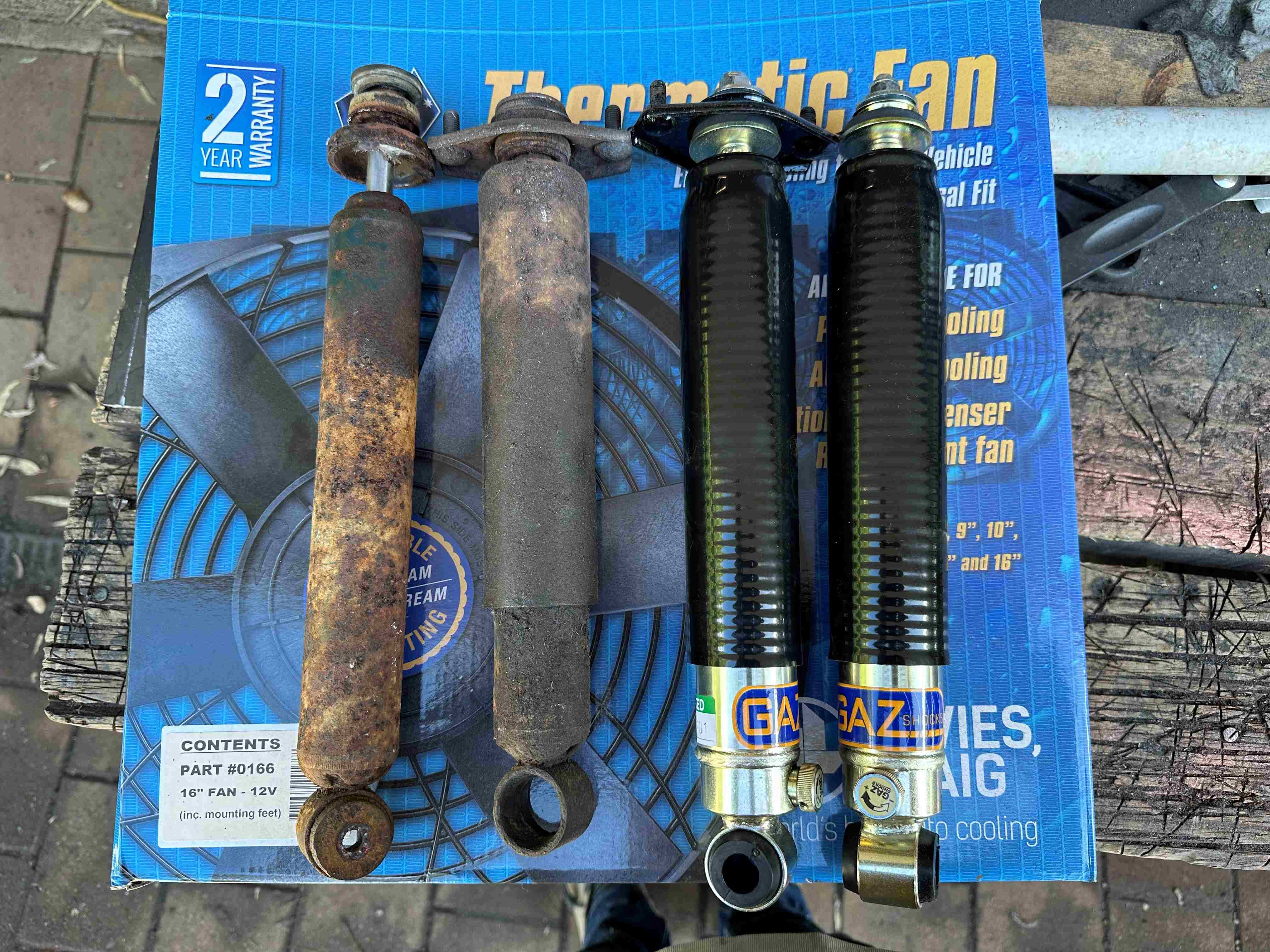
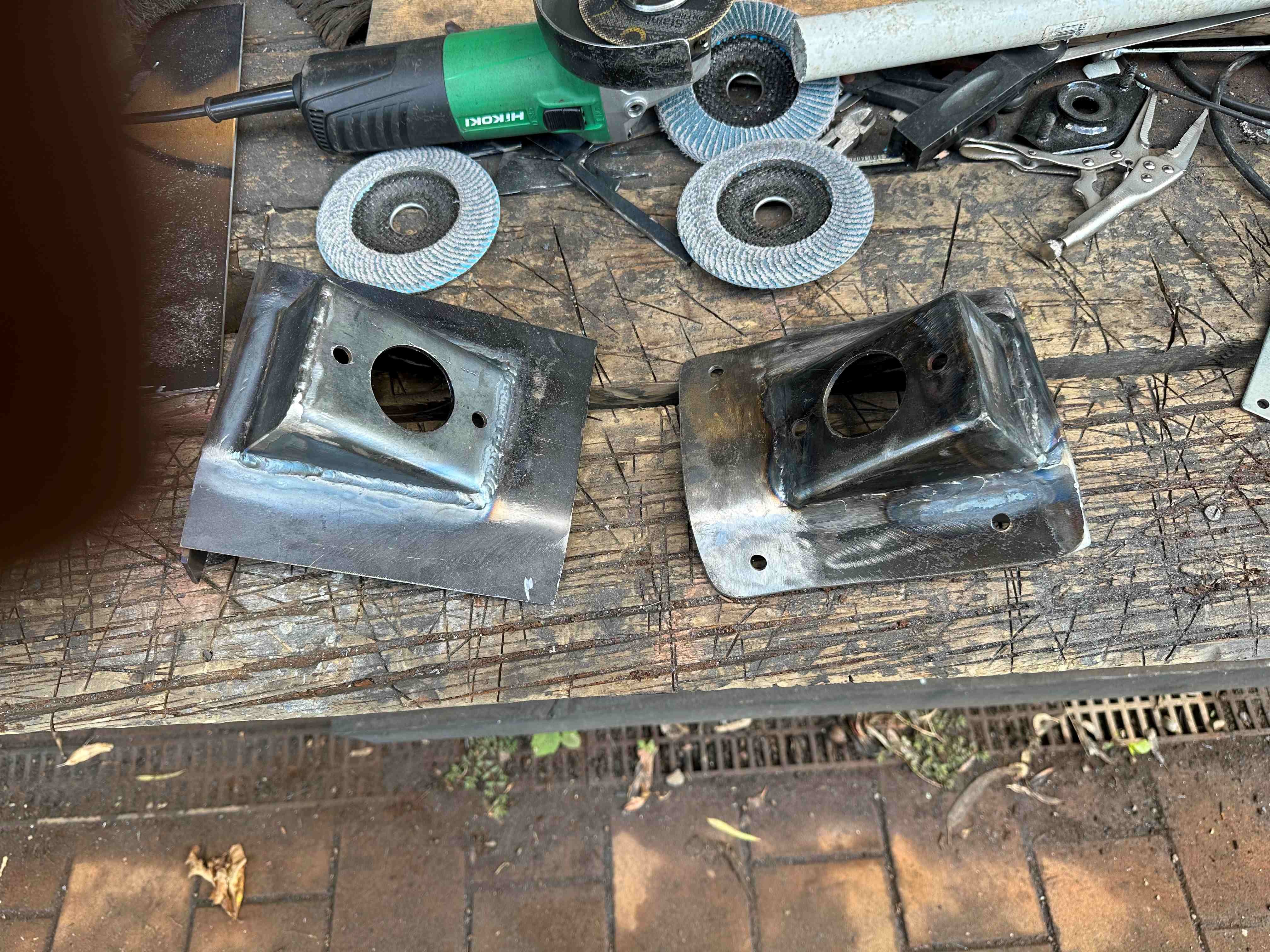
I thought I better get myself some new shocks. Looks like the use by date is up for the original ones. They did give me the ability to work out what I needed to do and also gave me the top mounting bracket. I didn't want to carry on with the shock mounts until I new they were going to mount the same way. Most replacement shocks for the Avenger are just the usual pin type mount. Gaz have made them as original, Cool. So now I know they mount the same I made up the passenger side mount. Still needs to be test fitted and trimmed a little. The drivers side I have ready to weld in once the weld through primer dries. Well tomorrow really as all this cutty grindy weldy stuff makes you thirsty.
1 point
-
Enough of that nonsense (press the sleeve out of a GN and run the piston in that in the standard cylinder to maintain std head) I went and picked up 2 engines tonight. One complete and supposedly running, although backfiring (has a China pod filter on it) and a second junker parts engine. Guy had lots of other parts, but I refused, because putting decent parts on this is a slippery slope to a 100hrs paintjob1 point
-
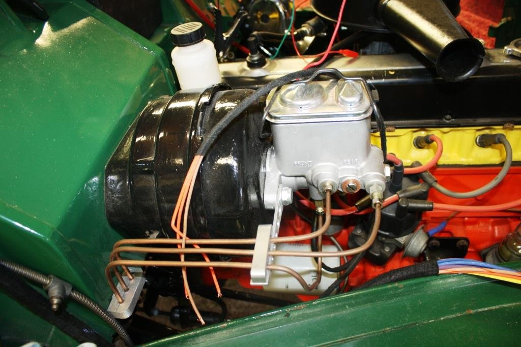
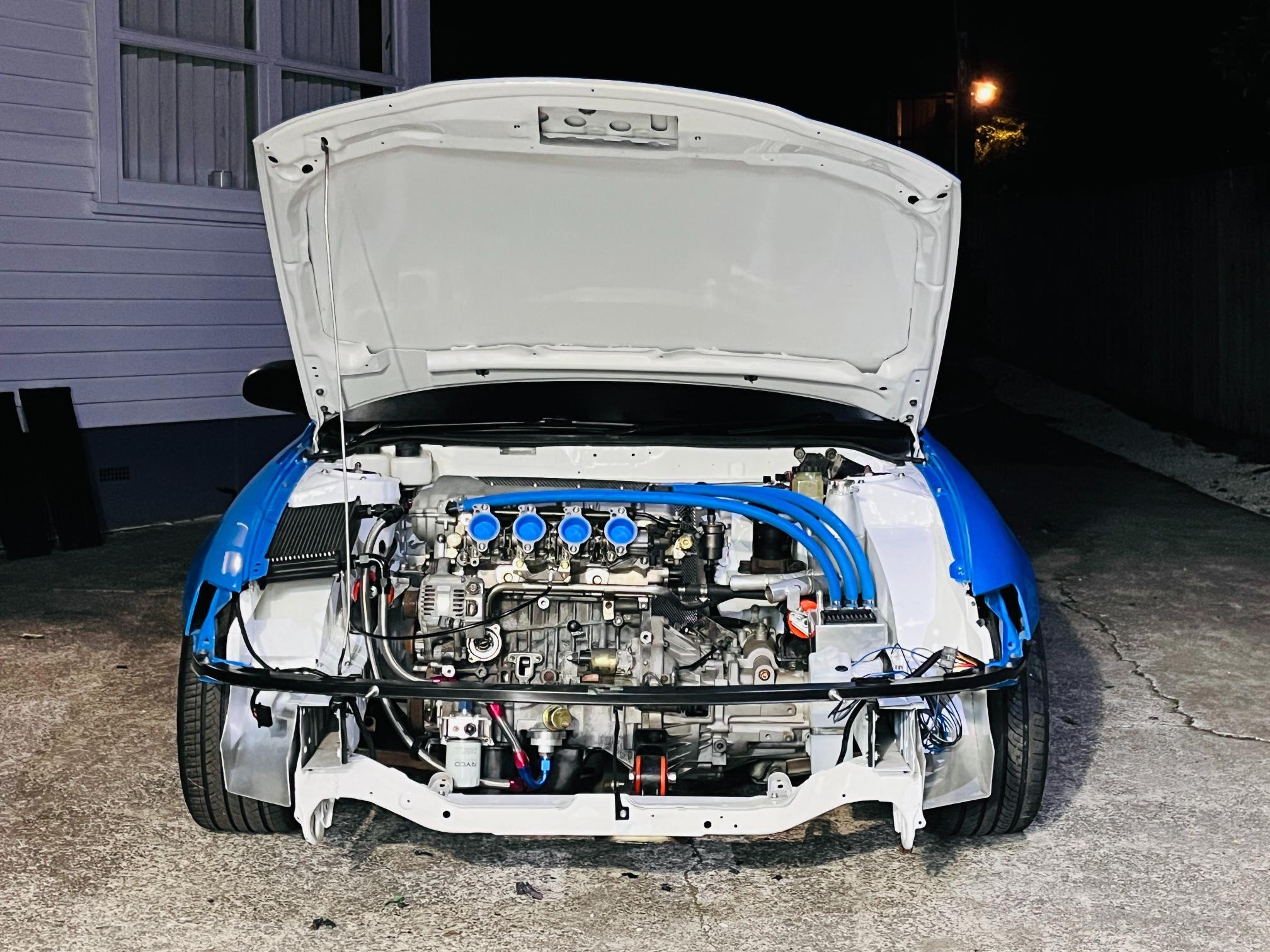
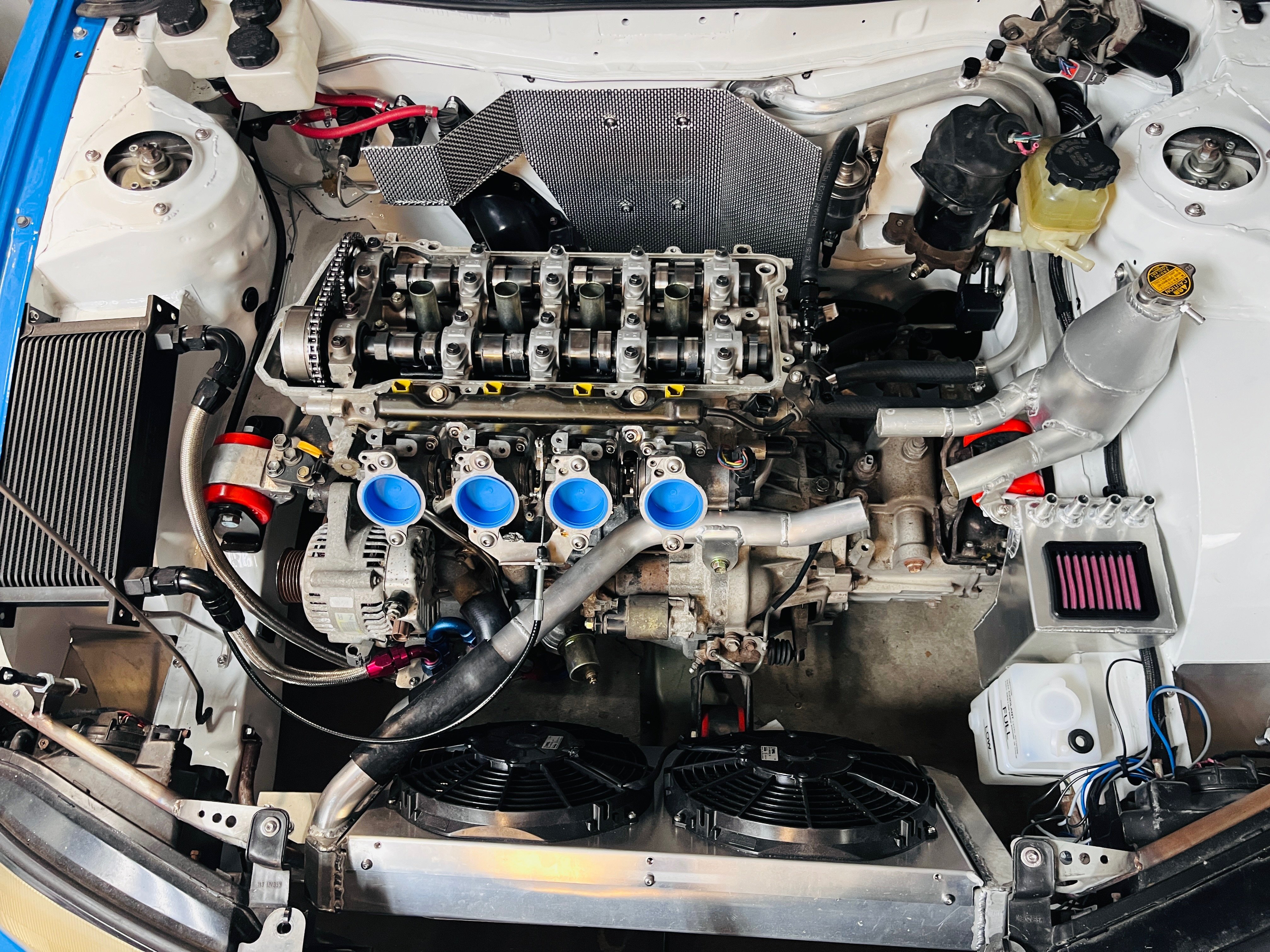
End of weekend engine bay shot. Made a nifty heat shield for the firewall to keep the important stuff like brake masters and fuel hoses from melting. Rocker cover is off getting a parts wash to get all the swarf out from drilling breather holes out. Sump needs to same treatment after I added an oil temp sensor hole.
1 point
-
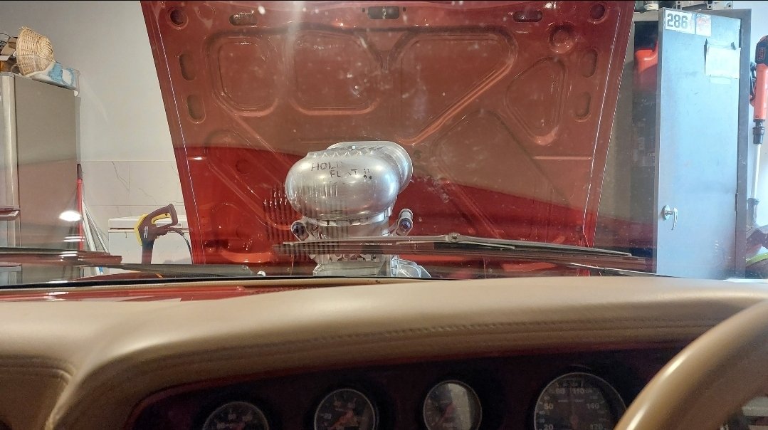
Been copping a lot of grief from many people lately about leveling up. So here it is! I dragged out the old 4/71 blower from the original RX4, and plans are being drawn up Been 20 years since I certed this on a car Stay tuned for a possible return....
1 point
-
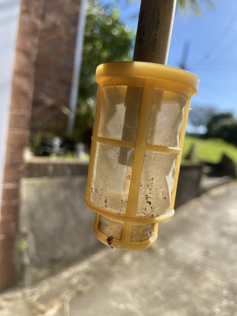
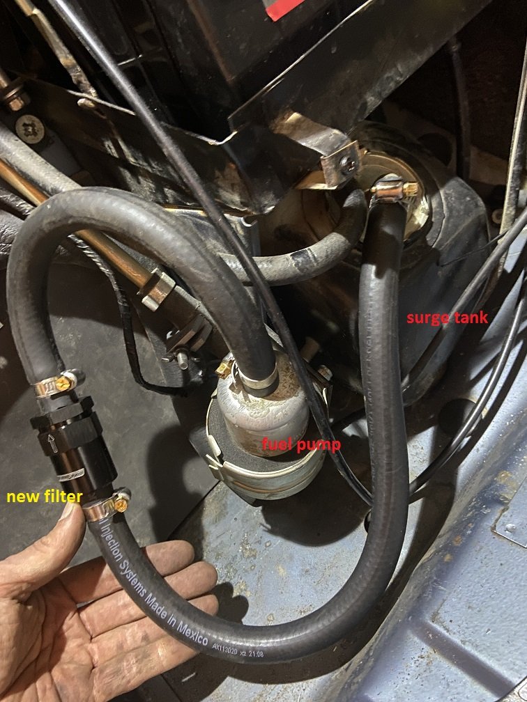
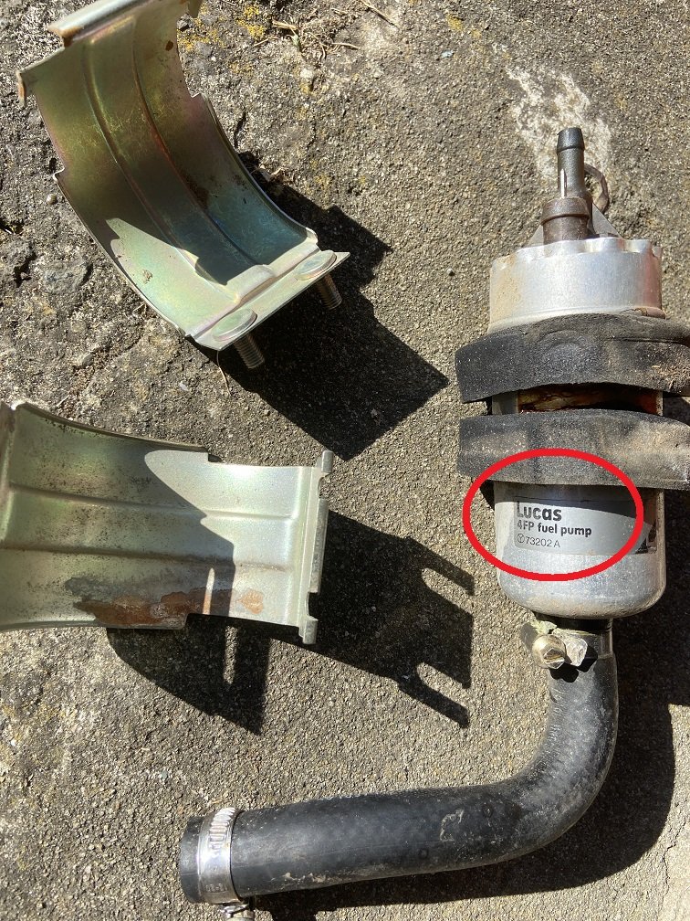
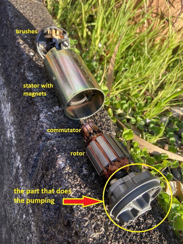
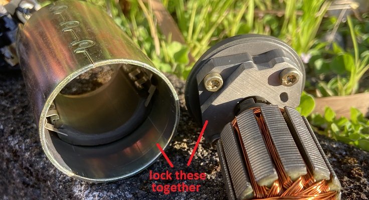
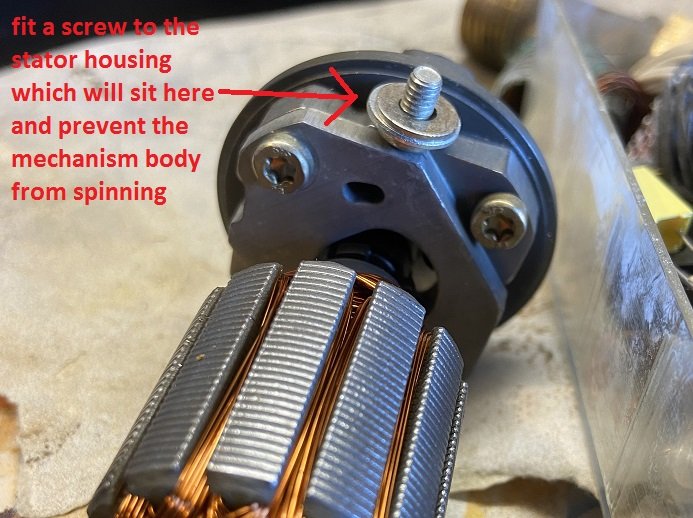
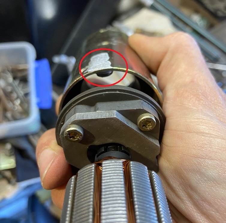
The verdict from the automatic transmission place was that the problem under hard acceleration wasn't caused by the auto! I was saved from having to spend lots of money on it. When the problem started to develop, it was only apparent at the top of second gear - it felt like the transmission wasn't making it into third gear, but in fact it must have been the engine running out of gas. Once again I'm lucky I didn't blow it up. I consulted the Barry Bible and apparently thirsty old Jags can suffer fuel starvation for several reasons: Fuel pickup blockage because the fuel tank likes to rust (my car has had a tank replacement in the past) Insufficient voltage to the fuel pump because of Lucas electrics Internal mechanical problems with the fuel pump Barry has answers for all of these issues, and he hasn't put me wrong before. His first recommendation is to remove the strainer from the pickup in the surge tank and substitute an external filter instead. I went and bought the required 1/2" size of fuel hose and filter, which of course you can't get from Repco/Supercheap. Then I took out the fuel pickup aaaand..... It's fine. I took it off anyway, because I'd already bought the parts to add the external filter: Ideally I'd find a bigger transparent filter which can be disassembled and cleaned, but maybe later. What's next... insufficient voltage. The voltage across the fuel pump turned out to be a constant 13.2V. That's presumably good enough - Barry said it should be at least 11V at idle. So the remaining fuel starvation cause is this: Barry describes this easy modification you can make to these fuel pumps to stop them playing up as they age. Yes you can just buy a non-Lucas fuel pump, but where's the fun in that. Plus this Lucas part is actually a Bosch part made in France. Apparently it's easy to un-crimp the top of the aluminium canister and mash out the internals.... I didn't find it easy. Violence was required. Here's what's inside: The part that does the pumping does not spin with the rotor. It has some internal impeller which is driven by the rotor, but the body of the mechanism needs to be held in place. The problem is that the only thing keeping it in place seems to be a rubber o-ring (not shown) pressing against the outer aluminium canister of the pump. As everything ages, eventually the part that does the pumping starts to slip and spin, meaning less relative speed of its impeller bits, meaning less fuel pressure. Then you get a crappy idle and fuel starvation at full power, and then you get burned pistons and you have to do a 350 Chev conversion. So here's the solution: how? By cunningly fitting a screw into the inside of the housing of the motor, we can lock the pump mechanism in position. The screw threads need to be ground off flush on the outside of the stator/casing so it can be jammed back inside the aluminium housing of the pump. By using the right number of washers under the screw head, it's impossible for the screw to come loose and fall out once the whole thing's reassembled. Genius. It was not easy to get the pump back together. It looks all mangled now and I'm surprised it still works and doesn't leak. I also replaced the regular fuel filter at the same time, because it had been installed over 14 years ago. Then I went for a drive, and yay, it seems to be fixed! The idle seems to be improved, which is something that has always bugged me. Most importantly I seem to be able to use full throttle right to redline again without the awesome AJ6 drinking its injectors dry. It's all the horsepowers that do it. Listen to them all on my crummy hand-held dashcam: All this mucking around has meant I still haven't changed any suspension bushes / subframe mounts or fixed the headlining. Hopefully I can fit some of those in by Nats.
1 point
-
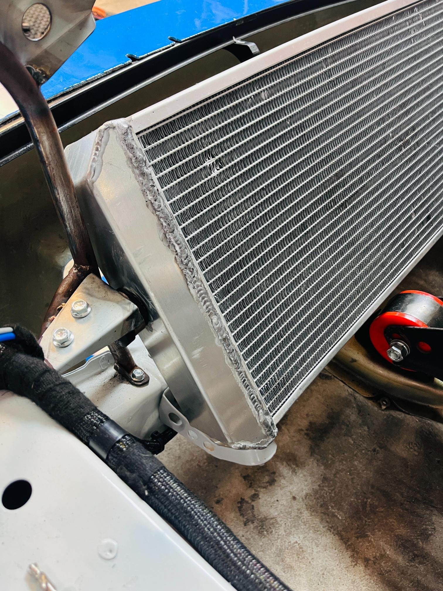
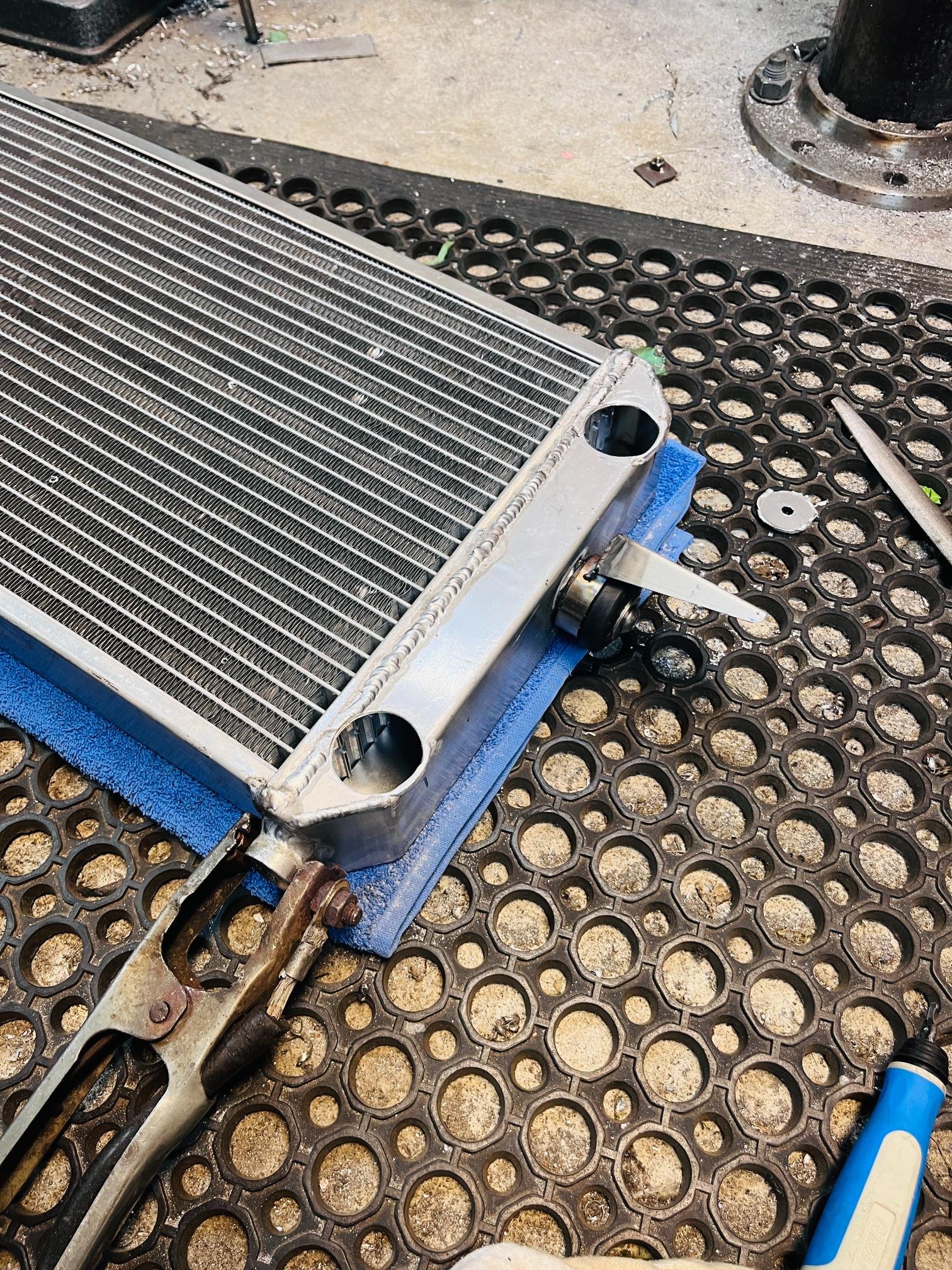
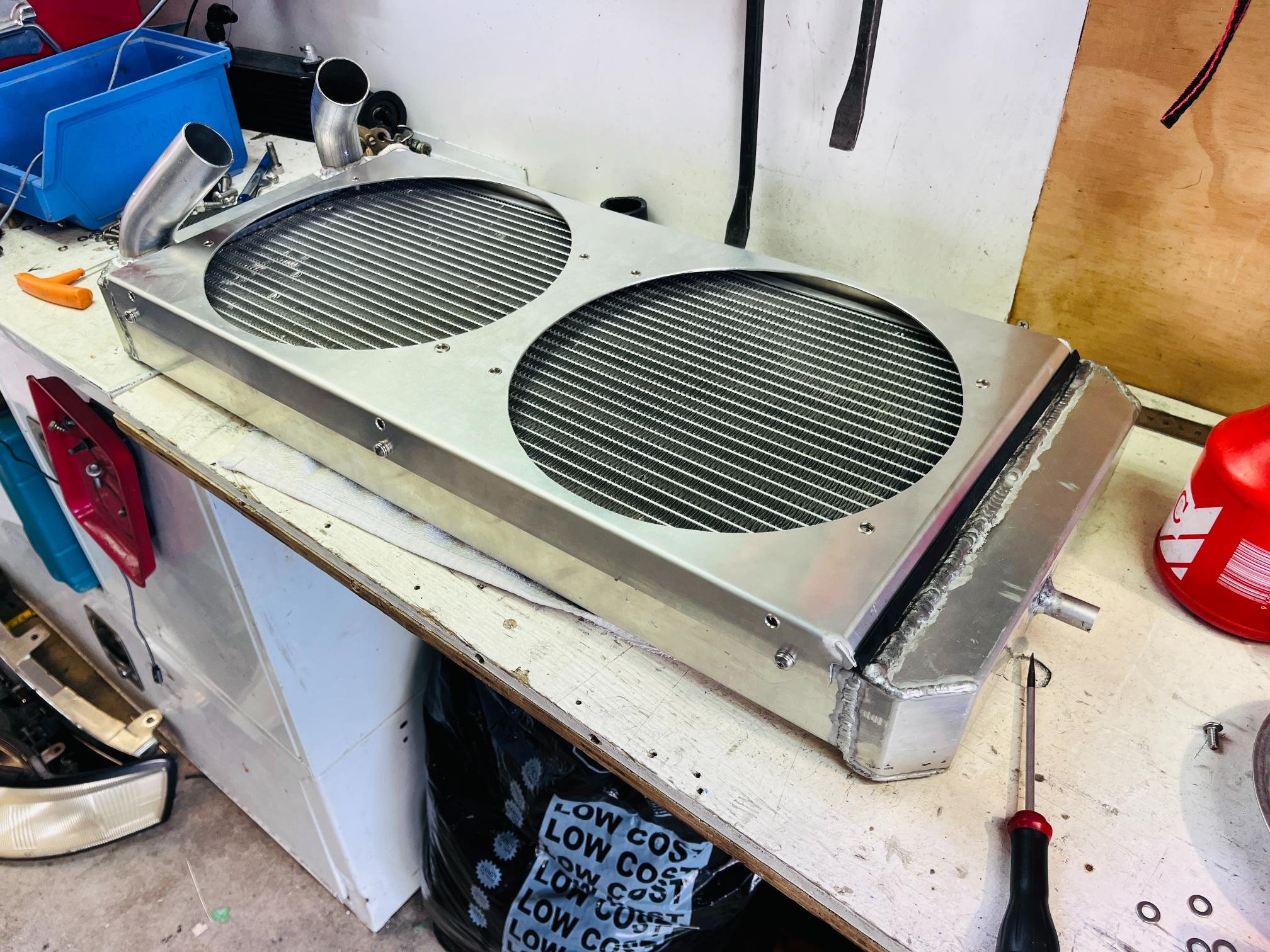
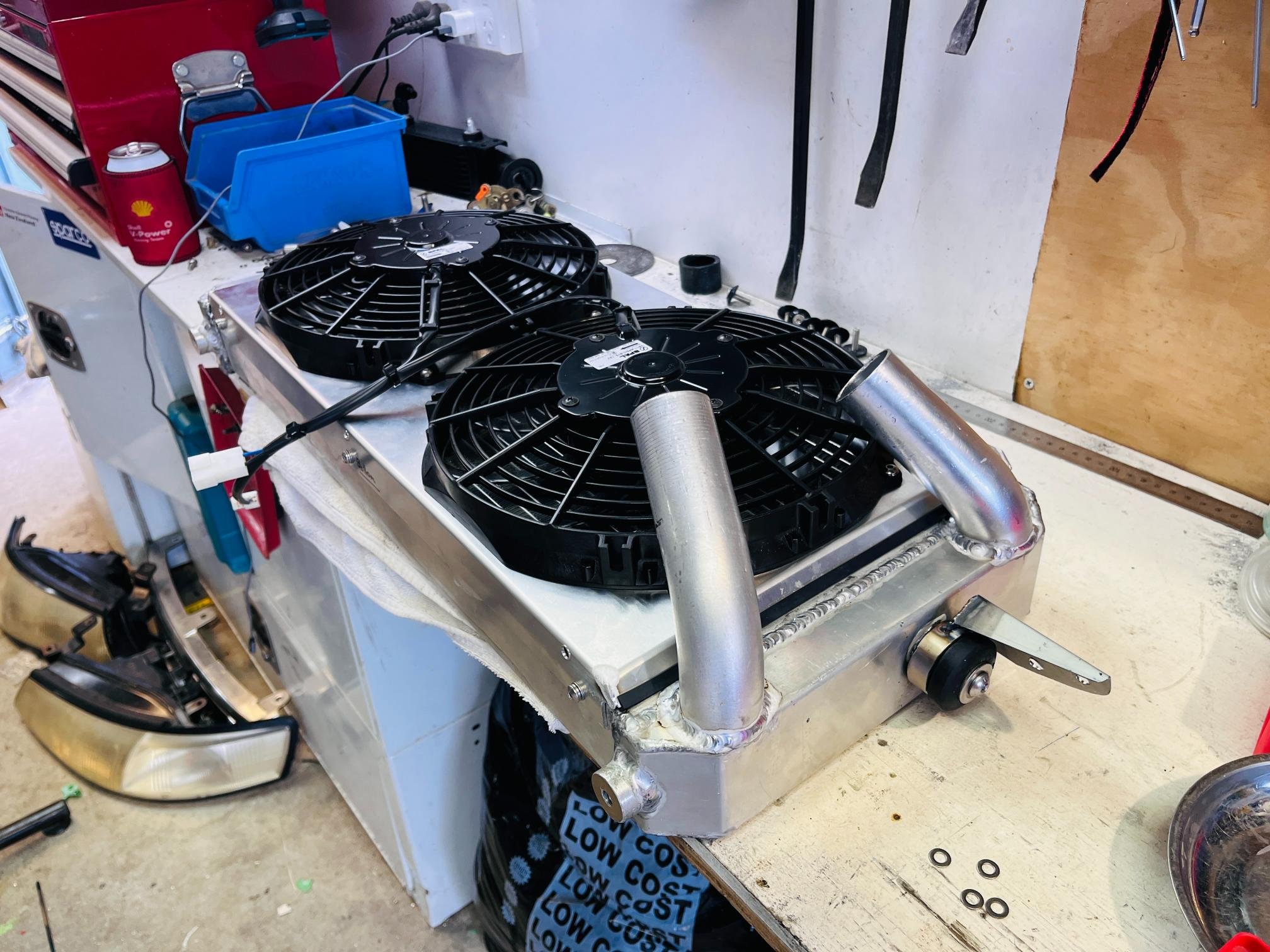
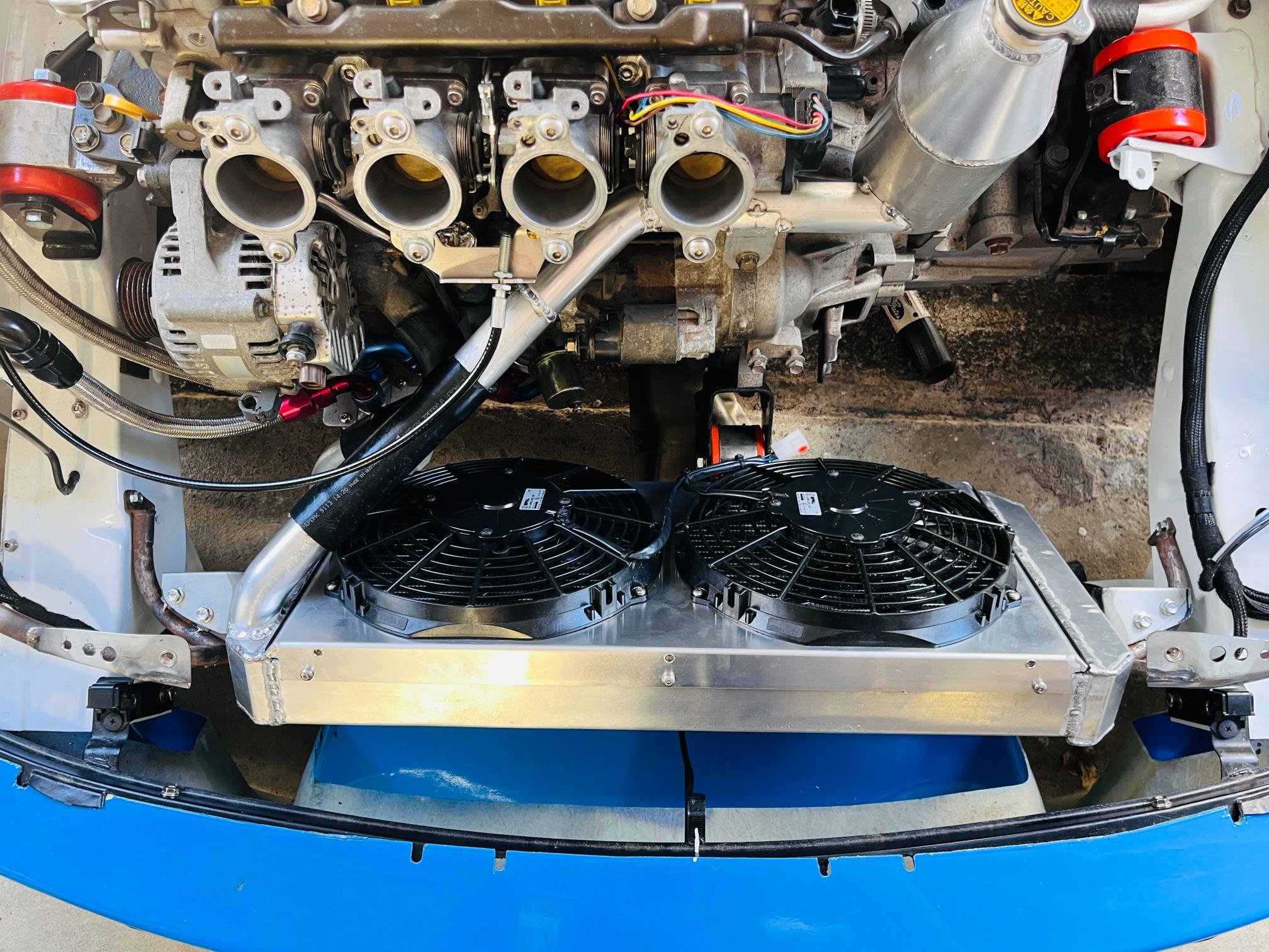
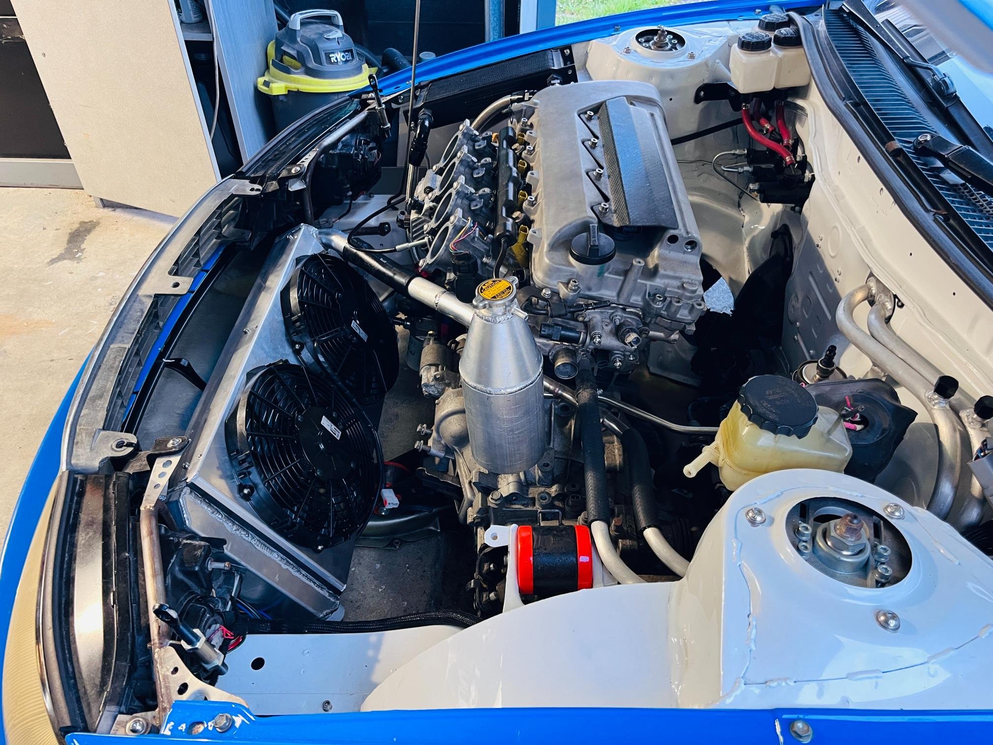
Got radiator side mounts, fans and pipework all sorted over the holidays. These had been holding me up until as their location determines a lot of other engine bay related constraints so was great to get it ticked off. Without a radiator cross-member mounting the top of the radiator was tricky. I ended up welding a boss on each end and finding a shackle bush to mount to the headlight frames. I bloody hope I never bend the front end cause everything will get damaged..... Might need a good crash bar post-cert for bumper-to-bumper racing! Made a shroud for the fans (which are the wrong direction currently due to a brain-fart on my part), mounted 15mm from core so hopefully enough to draw air from whole radiator surface. Have included rivnuts for future addition of bonnet ducting. Now I'm in the process of moving the header tank over to the guard to make the bonnet duct simpler. Should be a great layout when header tank, catch can, rad overflow, bonnet duct and airbox are all finished up. These may take a while to finalise as I'm focusing on jobs that get the car started.. ] This is a HUGE step for me. And super happy with how it worked out. The end is feeling a lot closer and achievable now! Just got to keep moving forward.
1 point
-
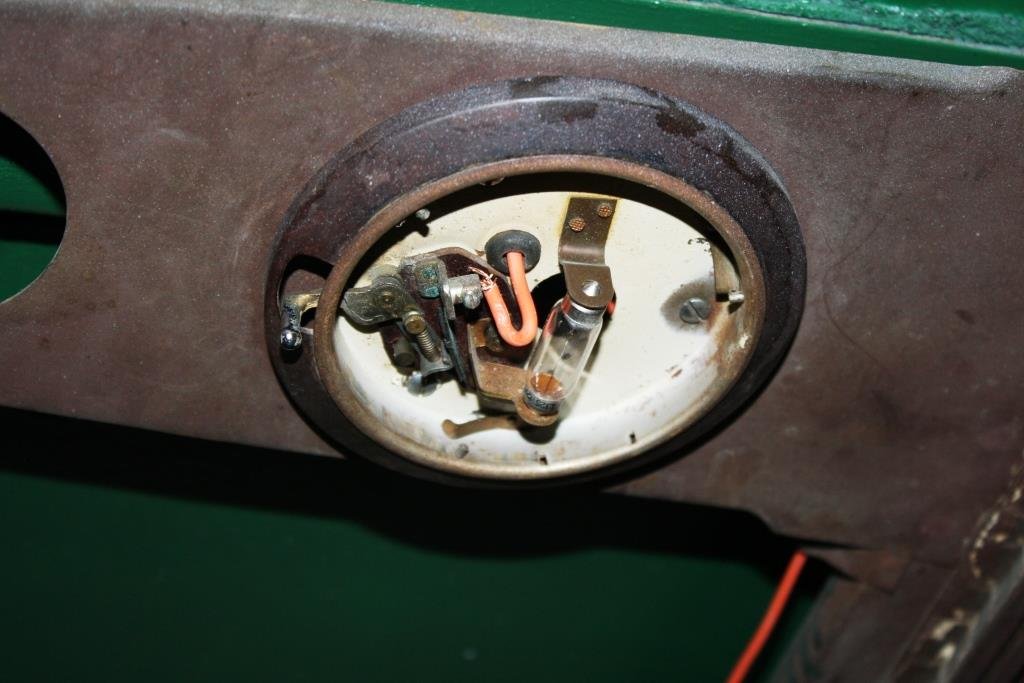
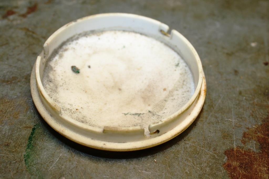
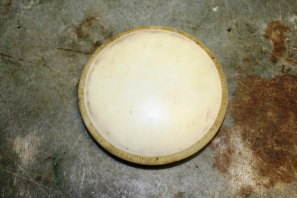
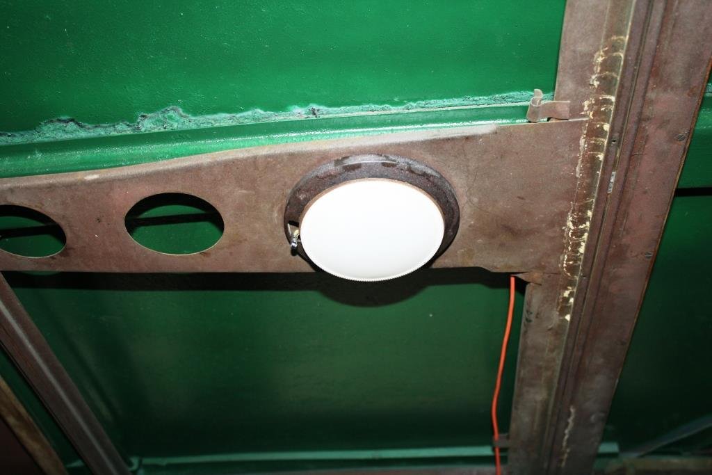
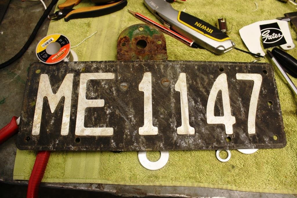
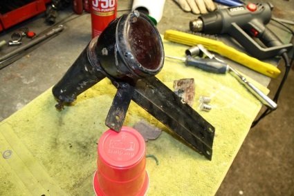
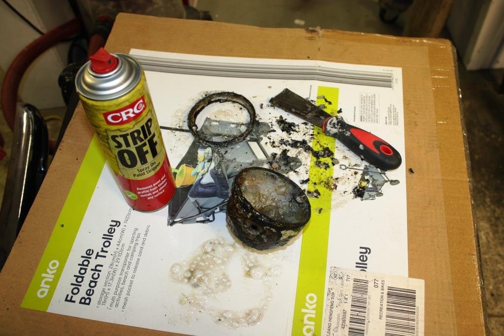
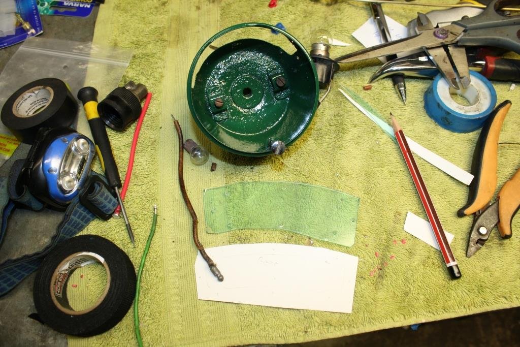
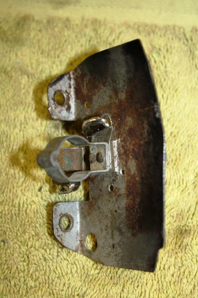
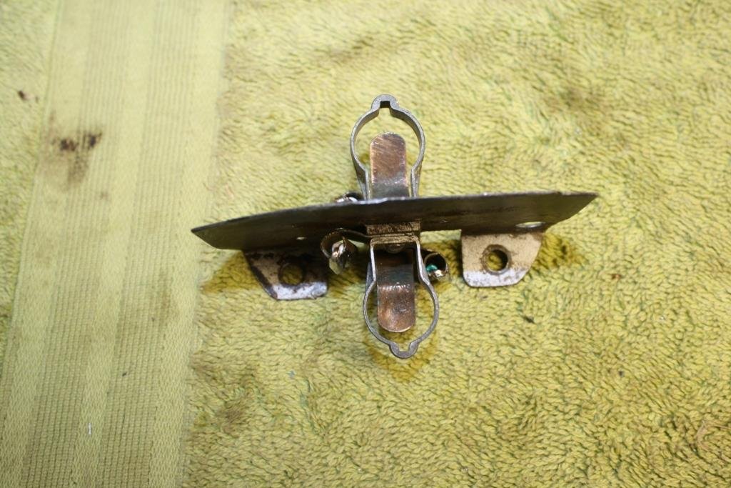
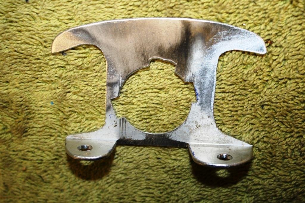
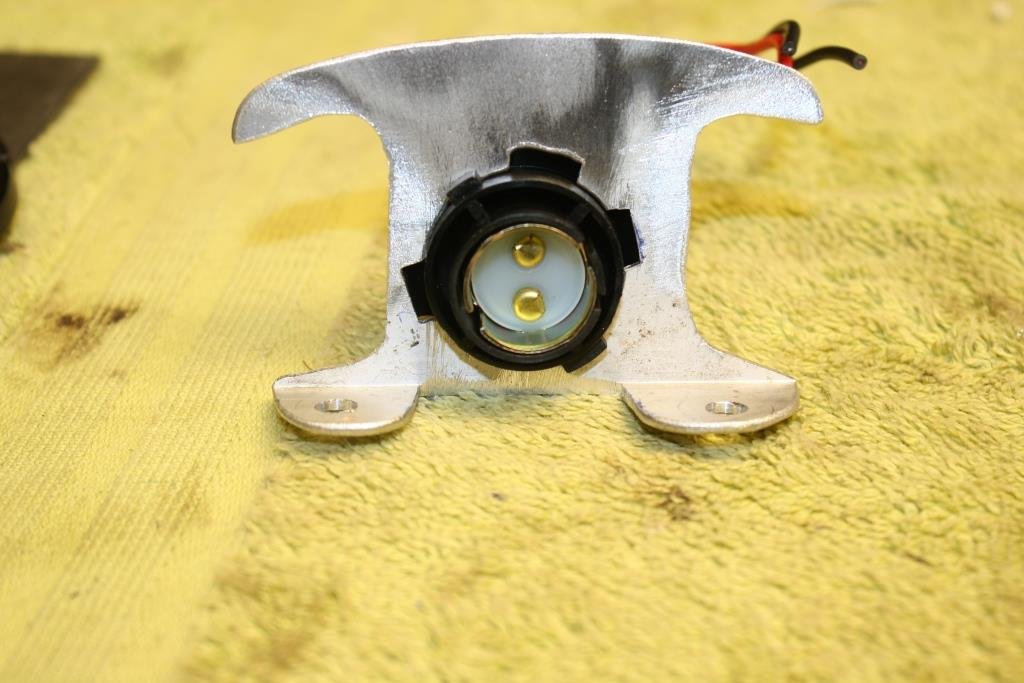
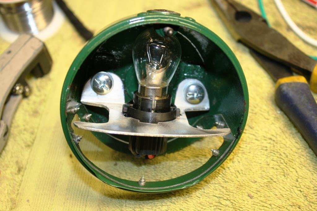
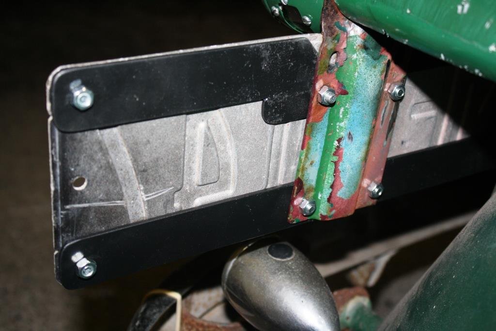
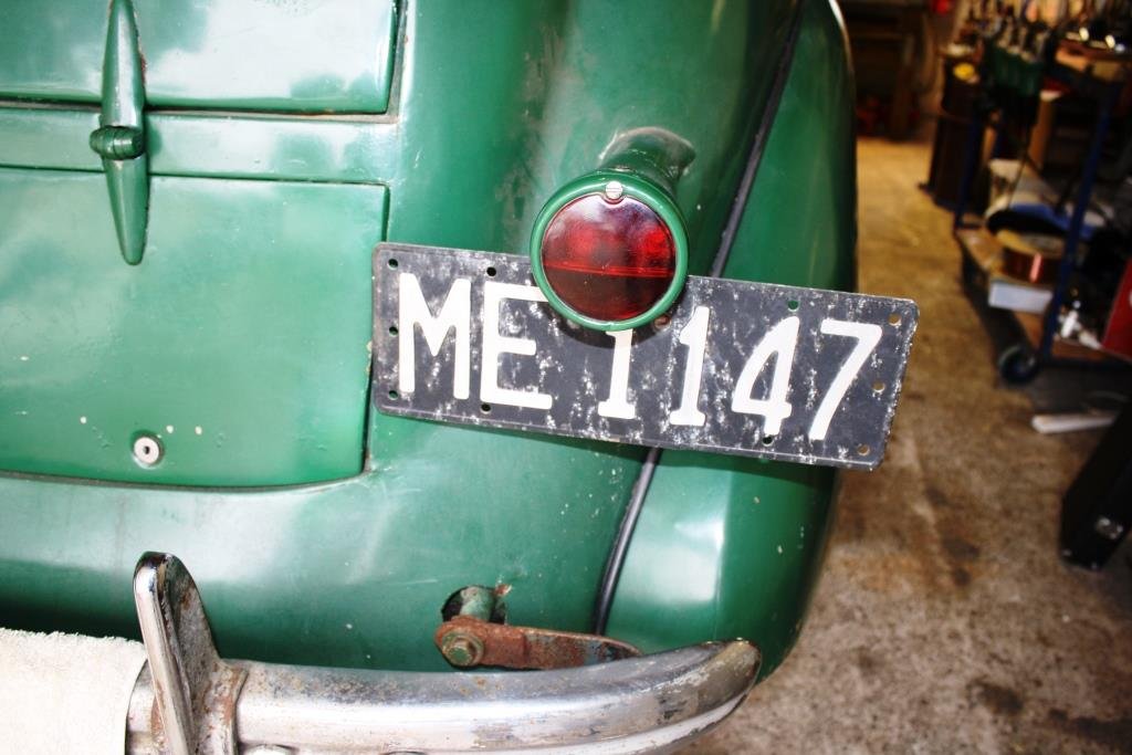
Working my way through the electrics….. This is all that was left of the original tail light, (i.e. the bloody thing fell off!). I started stripping down the tail light I’d got from the Vauxhall Car Club. Paint stripper, rust kill and paint……… I replaced the clear number plate lens with plastic cut from a welding helmet lens cover. The bulb holders were badly corroded and shorting out. I made the call to upgrade it and made one of these out of a piece of scrap alloy. It fits a modern bulb holder……… And just fits inside the housing. The number plate was a little bashed and battered so I reinforced it a bit. Still looking suitably bashed & battered but it all works!
1 point
-
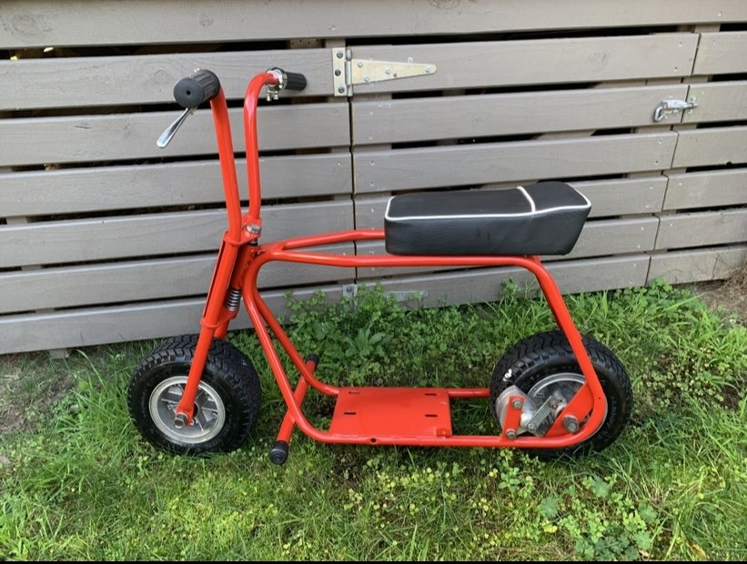
This is how the frame currently sits I also forgot to mention I had a new seat made which I may end up getting another as this one’s a bit thin and I’m trying to be as close to original as possible but I’ll see
1 point


.thumb.png.b2aee08688778d18bdc7b3e3c1852d9c.png)


.thumb.jpeg.384ff72c8d2b0ee0d34a7bdedb55bdcf.jpeg)

.thumb.jpg.570970b401ac8d26ce9af7c1bf2bd8cd.jpg)

This leaderboard is set to Auckland/GMT+12:00