All Activity
- Past hour
-
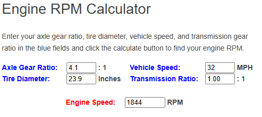
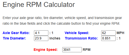
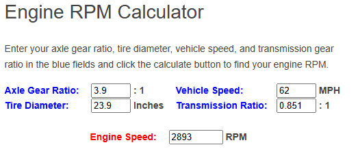
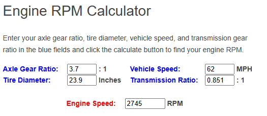
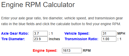
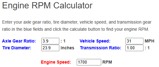
OK, sweet. Doesn't matter that you don't have an RPM counter, just makes it harder to verify the change to what you want with actual numbers. What gear do you use for around town at 50kms and obviously you're in 5th for 100. Here is your current setup. I have used 4th gear @ 50kph : 5th gear @100kph: So if we go to a 3.9 final drive ratio: 50 kph in 4th: 100kph in 5th: So if we go to 3.7 final drive ratio: 50 kph in 4th: 100kph in 5th: OK. There you can see the differences at nominal speeds. But what about 1st gear you say? I'm not going to do a @Roman spec graph for you which would be alot easier for your veiwing pleasure but the basics are this: 1st gear, 4.1 Final drive: 8kph = 1132 rpm 16kph = 2264 rpm 1st gear, 3.9 Final drive: 8kph = 1077 rpm 16kph =2154 rpm 1st gear, 3.7 Final drive: 8kph =1022 rpm 16kph =2043 rpm This would be easier, if I did an RPM to kph speed for you to see easier but because I'm lazy and cbf starting again, you can think about this the long way around it. But as it seems: 1st gear @ 20/21kph is the roughly similar revs at 100 kph with 4.1 ratio (2943 rpm ) 1st gear @ 20/21kph is 2800rpm with 3.9 ratio 1st gear @ 20/21kph is 2656rpm with 3.7 ratio Alot of funny numbers there. What I would do at this point, would be a cheap shitty RPM gauge that you can put in temporarily to see whats what. I question that you may be feeling like the revs are higher than you think which is not uncommon when you're sitting on top of the motor, not behind a firewall and alot further forward ( quieter ). The average becomes around 150 RPM in any gear in 0.2 change of final drive ratio. This also doesn't allow for wanting to change gears at different speeds with those without knowing what your RPM is in any gear/speed. Feels like dropping to a 3.9 may not be enough, but someone with more experience with your motor may be able to answer is the 3.7 going to make the motor suffer from torque. I'm almost about to question are yoou sure the gearbox is correct as the numbers don't look scary bad. TL;Dr - Not that certain I have actually answered anything or helped.

-
Cool bike, I like how the carb slide looks bigger then the piston...
- Today
-

Gibbon’s 1971 GT6 bothering - comment here
VitesseEFI replied to VitesseEFI's topic in Project Discussion
Nice pile of clean parts you have there! The chassis pic of the rear wishbone mount looks a bit like it’s had a minor shunt at some point and the wheel’s been hit with the force passed back to dent the chassis. Fairly typical Triumph injury but yours is a very light example. Double skinned at that point a some anti-crush structure. I have a much worse example in my carport that came with my GT6. Had 15mm of shims which was using all the bolt. Decided not to use that one! shifter mod looks decent. Interested to see how you mount it in the car. I struggled with the body on! -
OMC 4 LYF Y'ALL!
-
Well..... I wandered back out to get the garage to stir the porridge and but then got a bit carried away. The ultrasonic cleaner also heats so decided to try and unstick the piston in the caliper after it had been which I did successfully with some compressed air. Inside was gross, Also took to the master to see if I could get the circlip that retains the piston out. it's basically impossible to do without destroying the circlip but c'est la vie as the spainyards would say. As it turns out... it's a bit of a mess. I did buy a replacement master piston but for reasons I could never possibly understand the two sizes available were 14mm and 5/8th of three barley corns (ripe and dried laid end to end) I bought the 14mm. The old piston was not 14mm. Sooo. I've decided to bench the old master and grab a Chinese one for now. Maybe I'll revisit it later, but for not we're looking for progress not perfection. More... less soon.
-
Presents? thingsorganisedneatly So checked off the order and it all appears to be here. I decided to look into the front brakes. They do not look neato. A bit more disassembly of the master Turns out the ultrasonic cleaner really likes to mess with my phone camera, but this is what under the reservoir looked like. The brown stuff is dried brake fluid and it came out like very shitty cocaine. And the caliper Into the porridge they go! Side quest has progressed. I got the carbs cleaned up on the GSX500e and it now runs very nicely on all four cylinders at all revs. Still doesn't like a cold start very much but it's.. better. Booked for VTNZ to get certified on Monday so.. fingers crossed that exhaust isn't too loud. More soon.
-
For the purposes of getting the thing road legal I'm quite glad to report that it is in fact a muffler. Still sounds awesome though. I'll get a vid this weekend.
-
This is a good calculator to help you out; https://spicerparts.com/calculators/transmission-ratio-rpm-calculator https://tremec.com/aftermarket/resources/gear-ratio-calculator/
-
Gonna try and get a plate on friday. Wish me luck!!
-
Thanks heaps for the reply @440bbm and also for the offer of assistance. I have looked at a few of those online calculators, but the biggest issue that I have is that I'm not running a tacho in the van, so I've got absolutely no idea what revs I'm actually doing. What I was hoping to do was to work out the optimum ratio by using my gearbox ratios as a guide. So at the moment 1st gear has a ratio of 3.928 and it's hardly worth using with my current 4.1 ratio diff. The van comfortably pulls off in 2nd gear which has a ratio of 2.333. So to my simple way of thinking if I could find a diff ratio that would effectively turn my 1st gear into 2nd and so on that would be ideal. Sadly maths is not my strong point and I couldn't find an online calculator that could work this out for me. My gearbox is a Toyota G54 (5 speed) with the following ratios: 1st - 3.928, 2nd - 2.333, 3rd - 1,451, 4th - 1.000, 5th - 0.851. My rear tyres are 225/50/15 which works out at an overall wheel diameter of 606mm if the online calculator that I found is to be believed. Any guidance that you can provide would be greatly appreciated.
-
Dropped frame and bars to a powder coater ..
-

Random slightly cool stuff you built but not worth its own thread, thread
SOHC replied to h4nd's topic in Other Projects
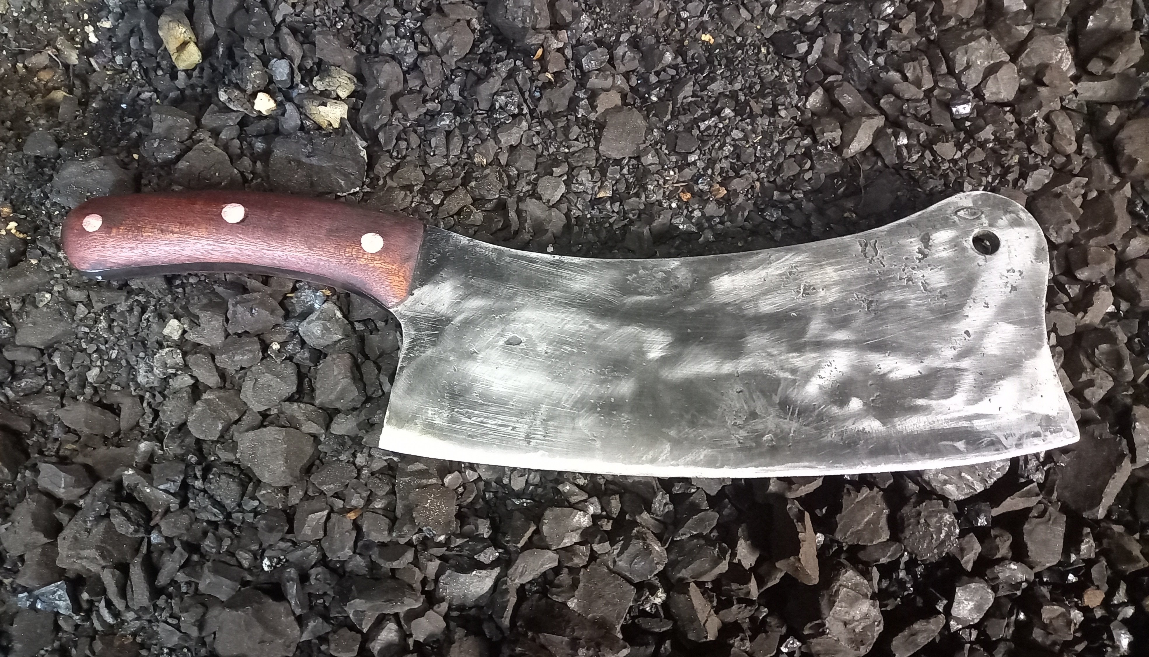
Heavy duty meat cleaver I forged, its not cut from plate, it will cut virtually anything and hold an edge, I spent the afternoon splitting fire wood with it and cut an old tire off a rim with it.
-

EpochNZ's Teenage Wet Dream Sierra Estate - Discuss!
locost_bryan replied to EpochNZ's topic in Project Discussion
Get your signwriter to do the NZ in the same green as th middle stripe, that was one of the approved variants of the logo.
-
Oh yeah plugs and leads arrived…. no spark Ordered coil and rotor dist cap arrived 6am this morning so will try tonight buuuut turns out these things run a mono leaf rear with 2 vertical air shocks run off a compressor and reg and two horizontal shocks air shocks are shot hence it squatting its arse these seem to be NLA 335MM compressed 485mm extended found these with similar specs (another 50mm extension) https://www.summitracing.com/parts/gab-49205#overview any reason they shouldn’t work? I’m sure I can manipulate the regulator to get the correct ride height/make it adjustable even Disregard, more googling shows rock auto list them for 1968 on ones it’ll be fiiiiiine
-

EpochNZ's Teenage Wet Dream Sierra Estate
EpochNZ replied to EpochNZ's topic in Projects and Build Ups
NNNoooooo............... Im penning a strongly worded letter to my signwriter. (In Comic Sans and Wingdings, of course.)
-
It'll it fails on that, I'll email them asking them to provide a letter that it's of the required standard
-
I did buy that from a Honda dealership too.
- Yesterday
-

Iwanttobeamole's Mates Mk1 Cortina - 4AGZE - Forgotten Princess.
Stu replied to anglia4's topic in Project Discussion
Sweet rig! Have wired up a couple of escorts with 4ages and confirm they go good! -
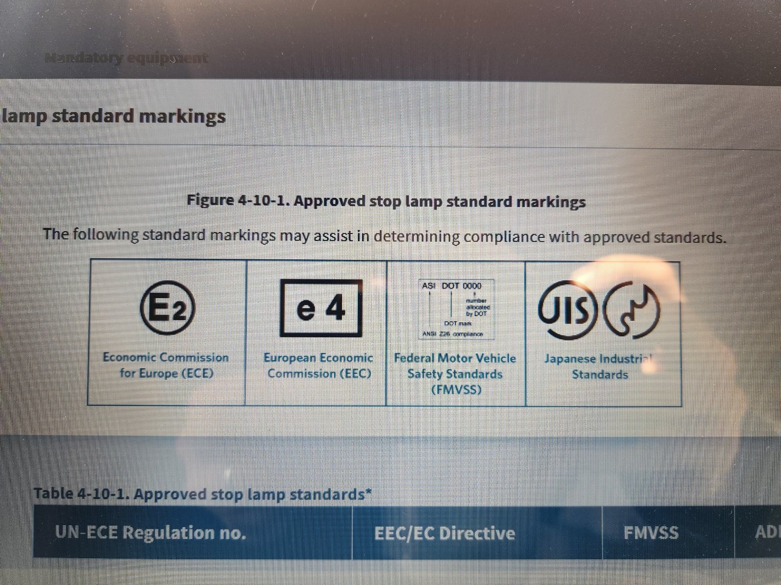
they are supposed to have the E marking on them (or equivalent). its in the entry cert paperwork if you are looking for it. china will put an e on anything you want, and i recall a wof doesnt need the e you can of course put some big ugly definately road legal gn125 lamp ziptied on for the inspection and then remove after for a small one, i did something like that for DR200 For motorcycle (Class L) this is apparently only required if built after 1st jan 2006, for brakes. Indicators are 1996. Also only needs to be shown to.comply however that is, but just easier to put modern complying ones on for thr inspection tbh
-
Motorcycle re-vin question. Do the lenses all need to have the factory markings on them? (Someone told me they thought they did) I have all genuine Stanley (oem honda) indicator lenses. But the stop/tail lens is a generic replacement one.
-

VGs Little FJ40/Off Brand Power Wheels & Trailer
Vintage Grumble replied to Vintage Grumble's topic in Other Projects
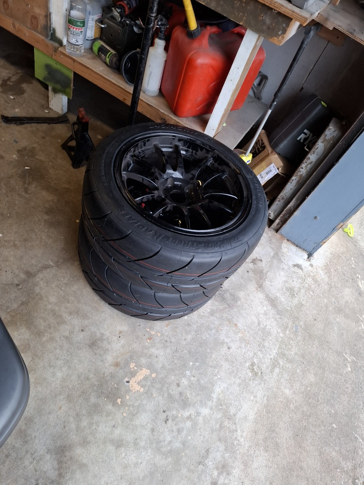
Recently got a bit more done on the trailer. Made sure it was about the right size etc, and made the up rights/sides. For ease of use and simplicity, the front and back tailgate board things just slide into slots made from angle and flat off cuts, Then I figured out where the axle needs to be, then whipped up said axle on the BIL's lathe, made some mounts and welded it on, As you can see in the background of the pic posted above in the last update, the alloy wheels were very oxidized (they have been outside for years) so I gave them a water blast, spray painted them black, and then buffed the paint off the face of the wheel to make them all shiny again. Slapped some tyres on that match the cruisers, and good to go. Then I whipped up some mud guards. Decided just to make them out of 3mm thick steel and not bother with mounts, and just weld them directly to the frame. Found an off cut of steel, cut the desired shape out, removed the rust, and put them in my fancy press brake and bent them into shape. I don't know why, but I find the little mud guards soooo adorable! Now I just have to cut and mount the wood, paint everything, and its done. Regards VG. P.S. Say hi to your mum for me.- 49 replies
-
- 11
-

-

-
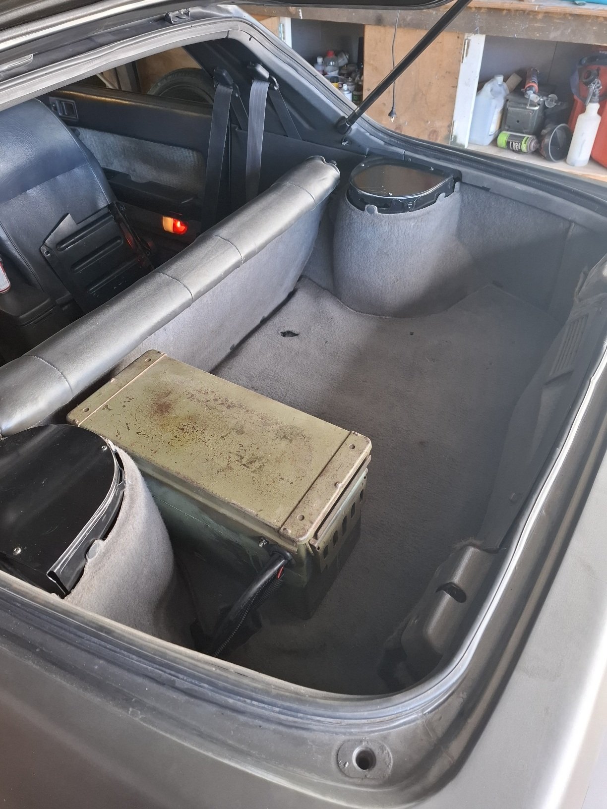
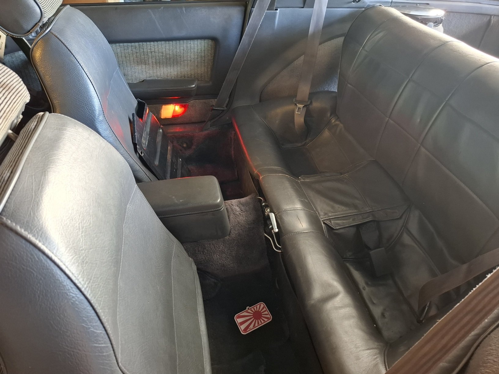
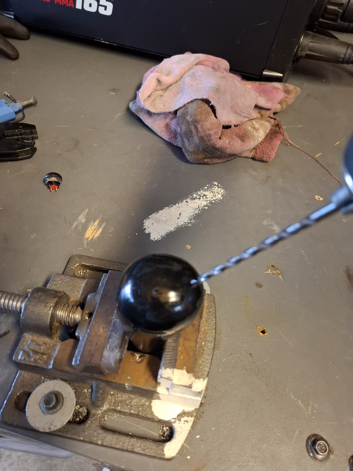
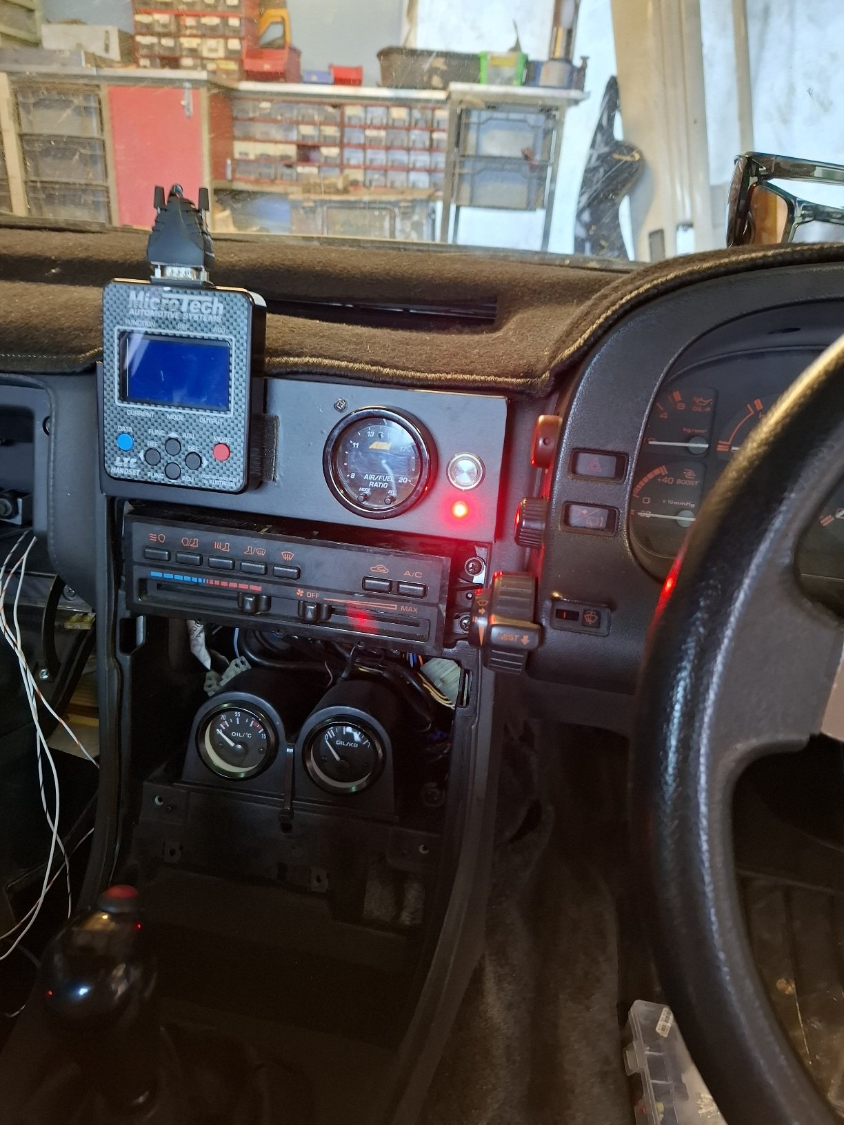
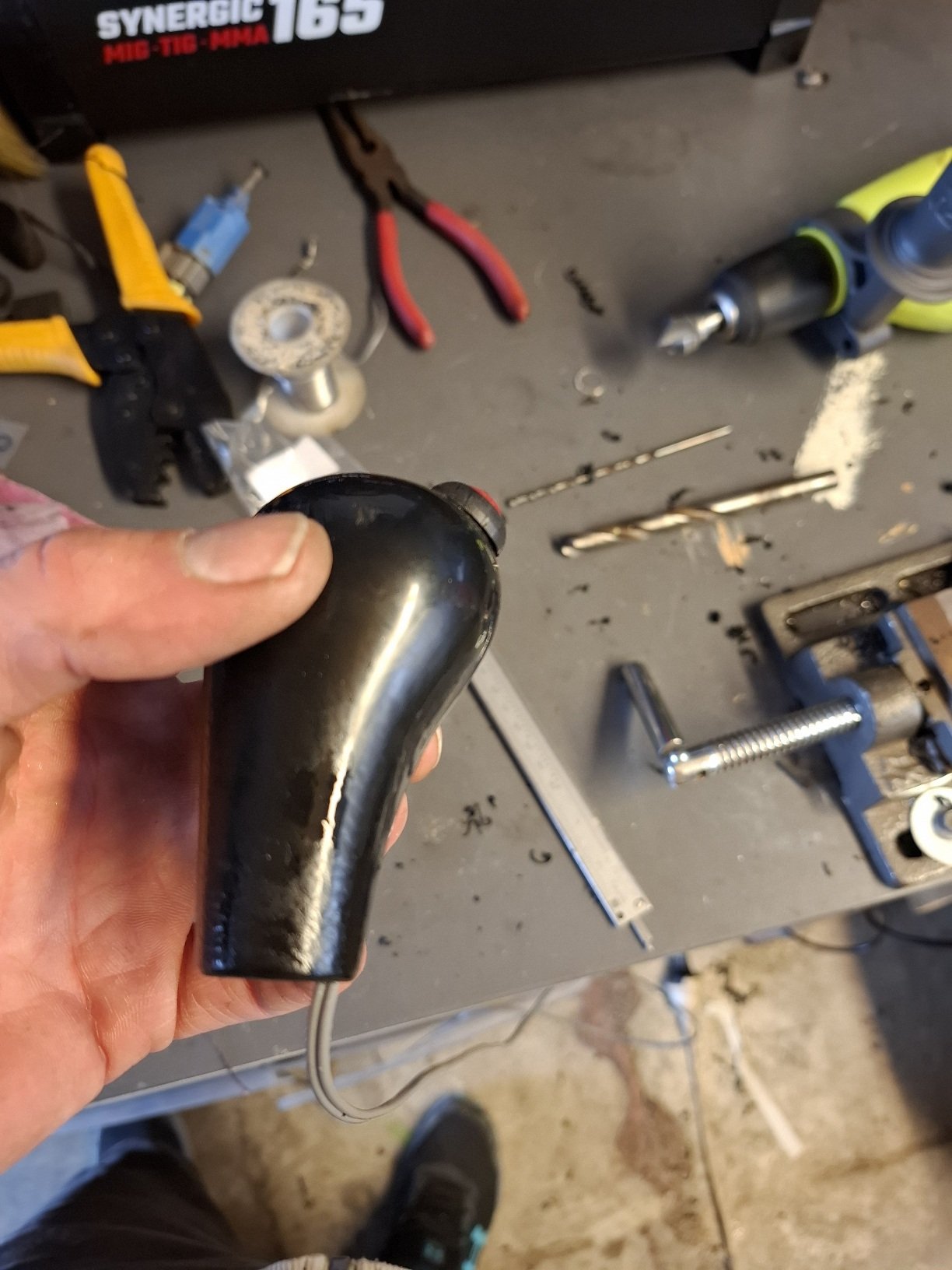
Found rear seat and carpet etc Went to jaycar and got a shift light, and a momentary button for launch control, so when it gets final tune that will be an option, drilled through the gear shift but doesn't interfere in the thread or how you put it on.. you do have to press it in fairly hard so wont hit it on accident shifting gears etc, both go through relays and fuses, i may change it to steering wheel maybe will see how it works.
-
Gibbon’s 1971 GT6 bothering - comment here
VitesseEFI replied to VitesseEFI's topic in Project Discussion
Yeah….. looks odd on those wheels too. In answer to your propshaft question…. I don’t think there’s much to be gained buying an MX5 propshaft. I’ve got 1 1/2 here because they came free with very cheap gearboxes and the half does actually slip snugly over a random Triumph section I had kicking around. I even though about welding them together myself….. until I considered how close it runs to my arse! -

2026 McKenzie Moped melee. 27/2-2/3 2026.
Reliables2k replied to RUNAMUCK's topic in South Island Region
-
Giz a hoon g 😇