
Leaderboard


Popular Content
Showing content with the highest reputation on 02/03/24 in all areas
-
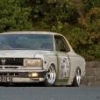
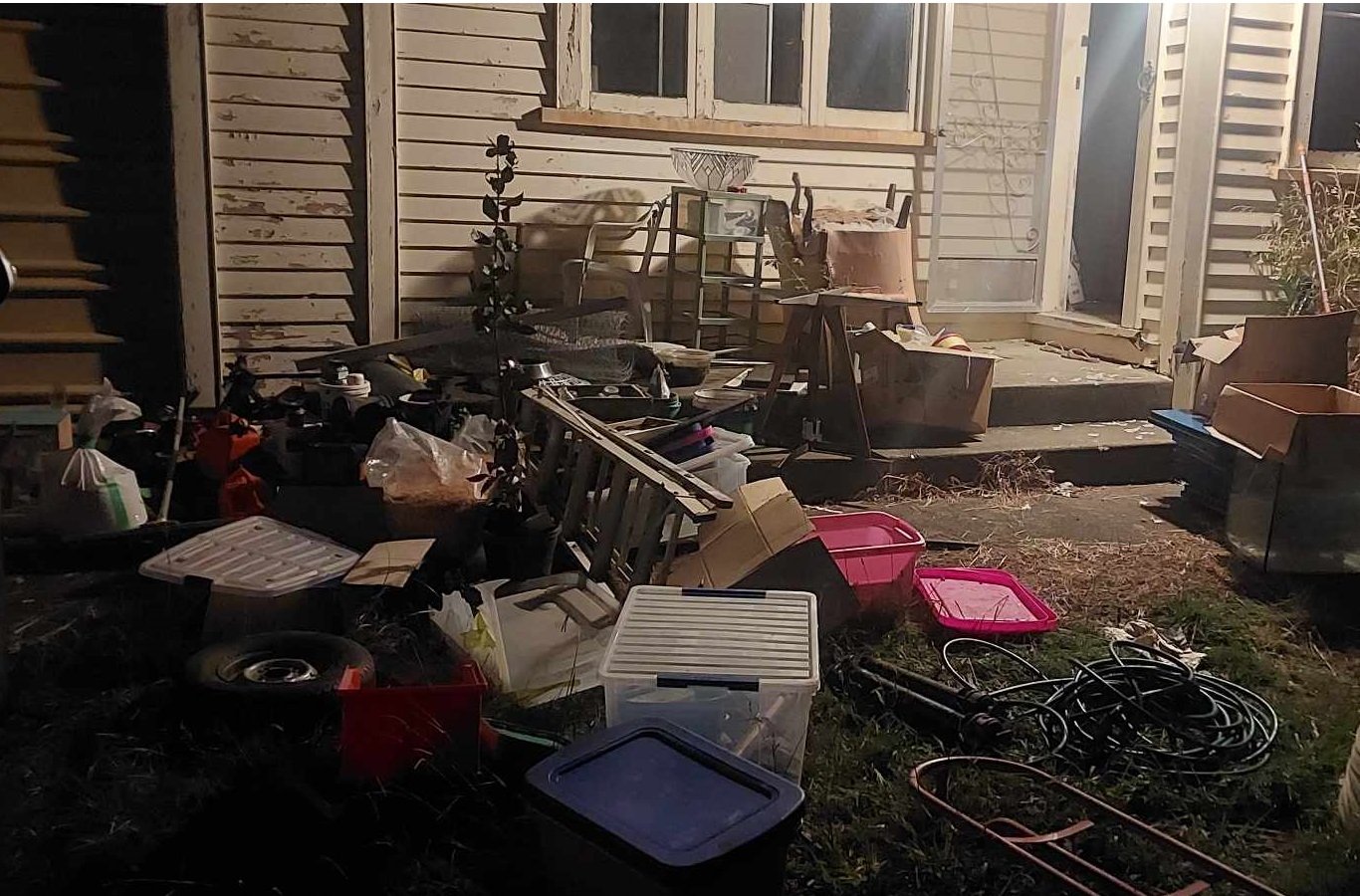
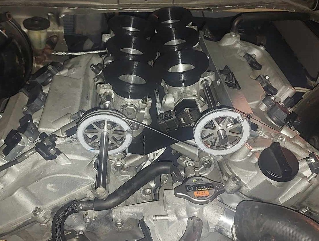
Alright so as of yesterday I'm finally out of mortgage prison! I finished moving house with heaps of time to spare, I definitely wasnt biffing trailer loads of stuff onto the lawn the night before settlement. I got some throttle pulleys cut from stainless. I'll put a radius on the inside of the pulley edges and deburr a few spots, but on the whole they came out really nicely. Quite heavy though, probably could have made some parts thinner. (Everything 2mm stainless) It's looking like it'll be fiddlier than expected to balance the cable length and pulley positions to get the banks even. One thing that I didnt take into account is that there is no tolerance for having a cable that is "overlength" as you physically cant slide the protruding end of the cable into the pulley. However I could probably chop out the relevant section of the pulley to allow this without any issues, as these are still significantly beefier than they need to be. I need to make some end stops of some sort to stop the throttle rails moving forward or backwards so everything stays aligned correctly. You may notice that in this photo I've got the linking cable on the wrong way up. It looks dumb having these on the front of the motor, but down the back is getting very crowded and I've got ants in my pants to get this damn thing fired up. I got the throttle rails drilled, took about 3 hours to drill 6 holes! We had to grind flats onto the rod to get through the hardening. Otherwise carbide bits didnt even make a dent. Next jobs are to print a final iteration of the manifold from Nylon, get fuel lines connected up, and keep working on the exhaust. Then I'm preeeeety close to firing it up!
 15 points
 -
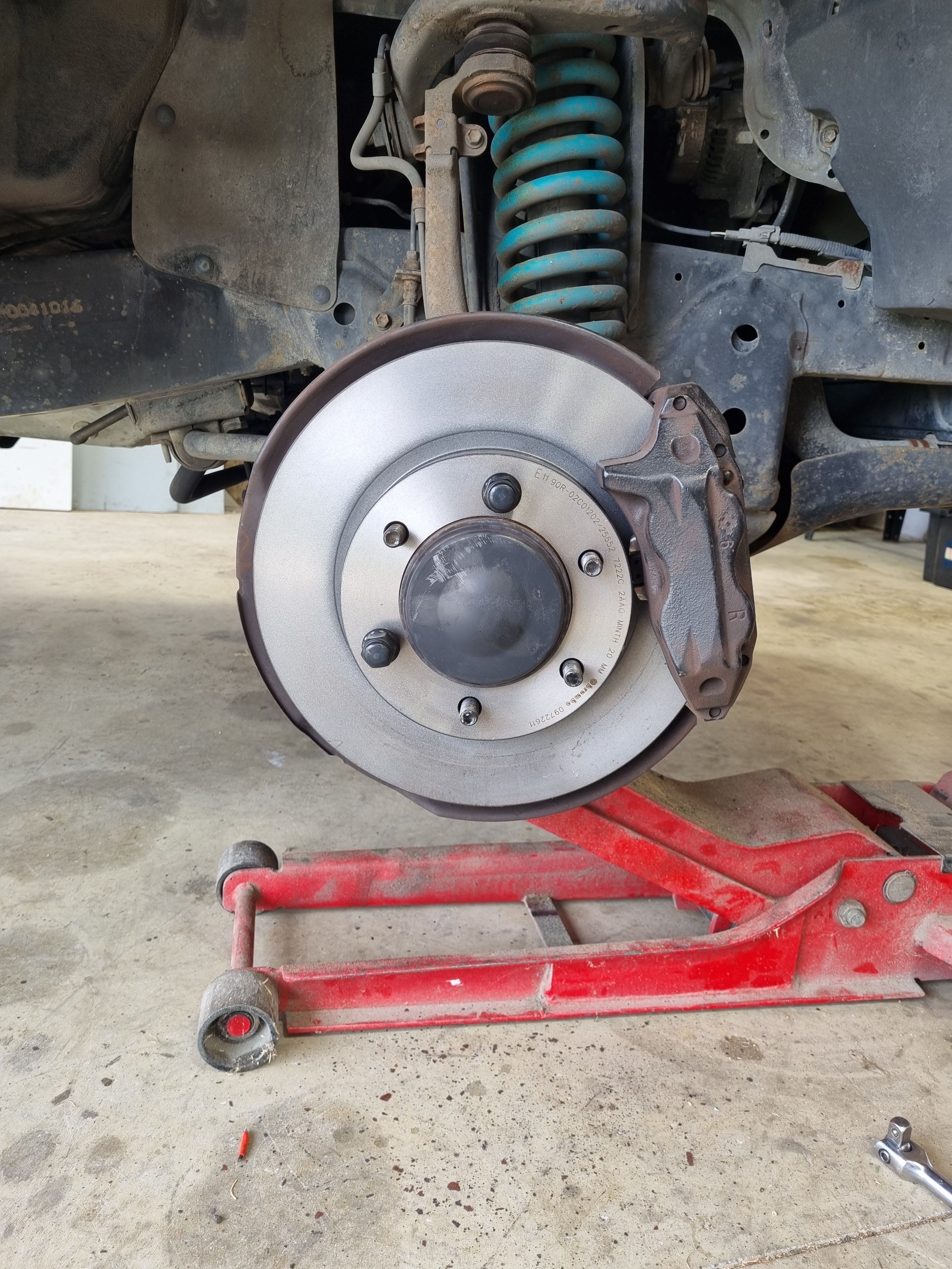
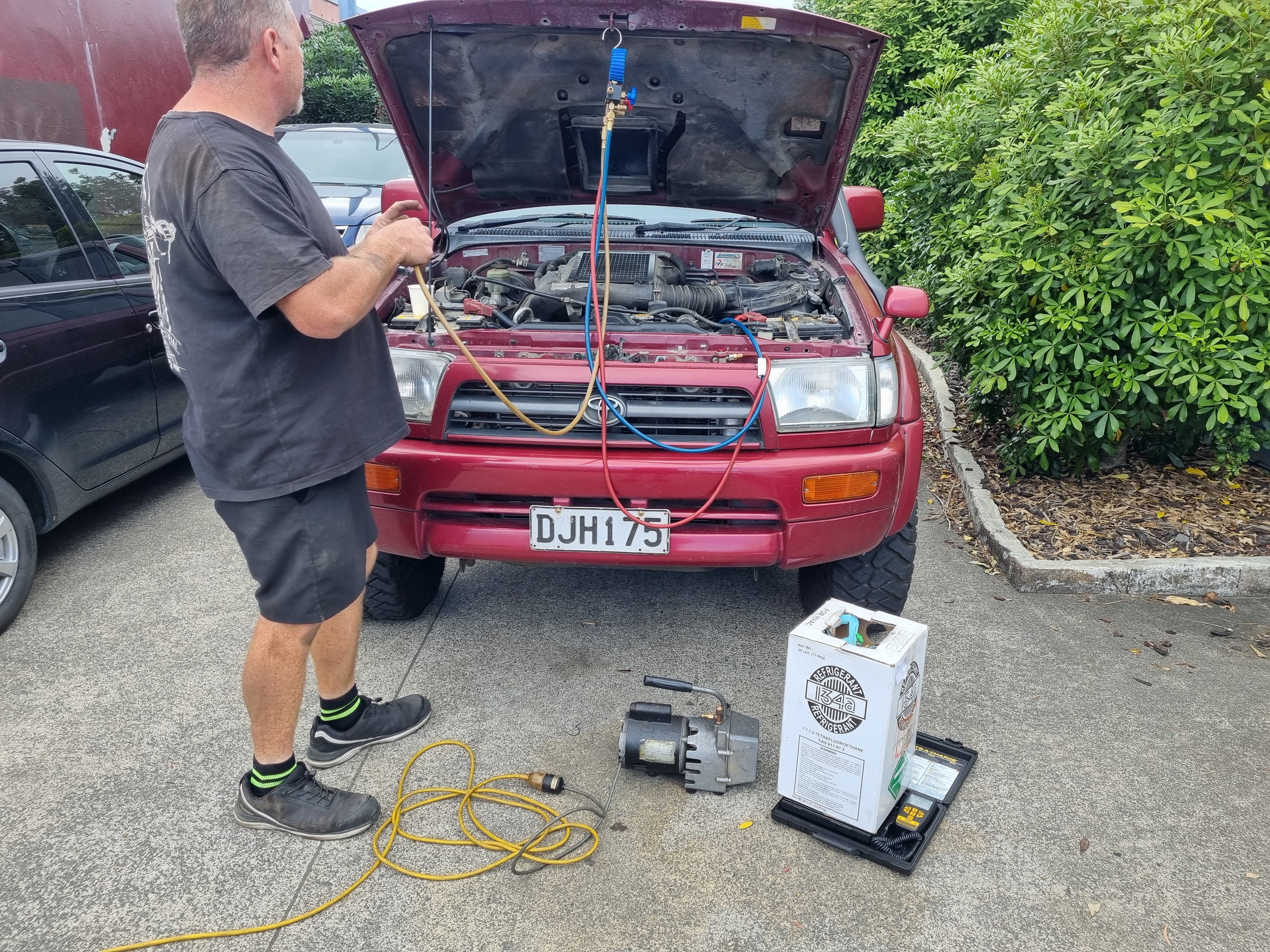
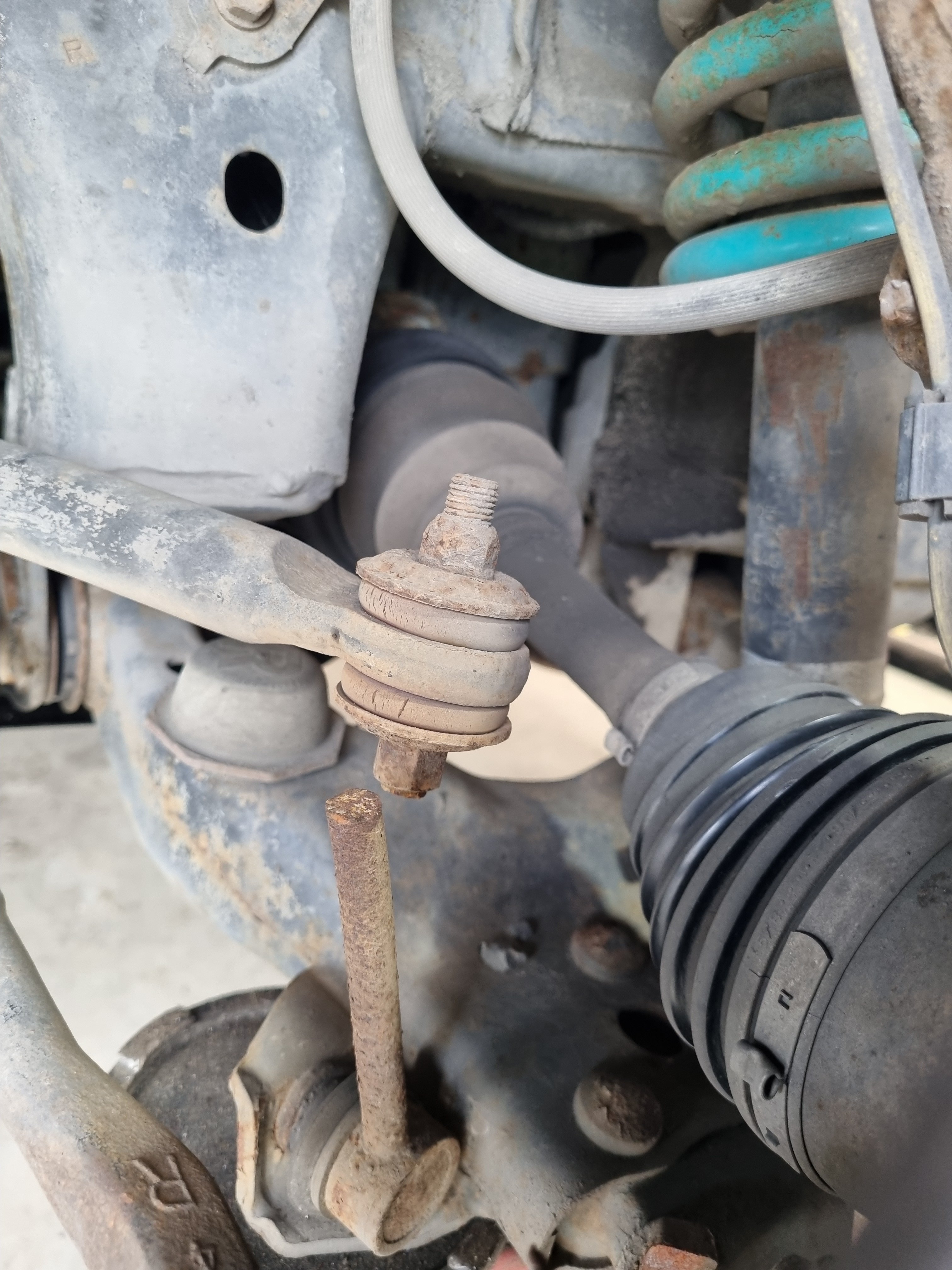
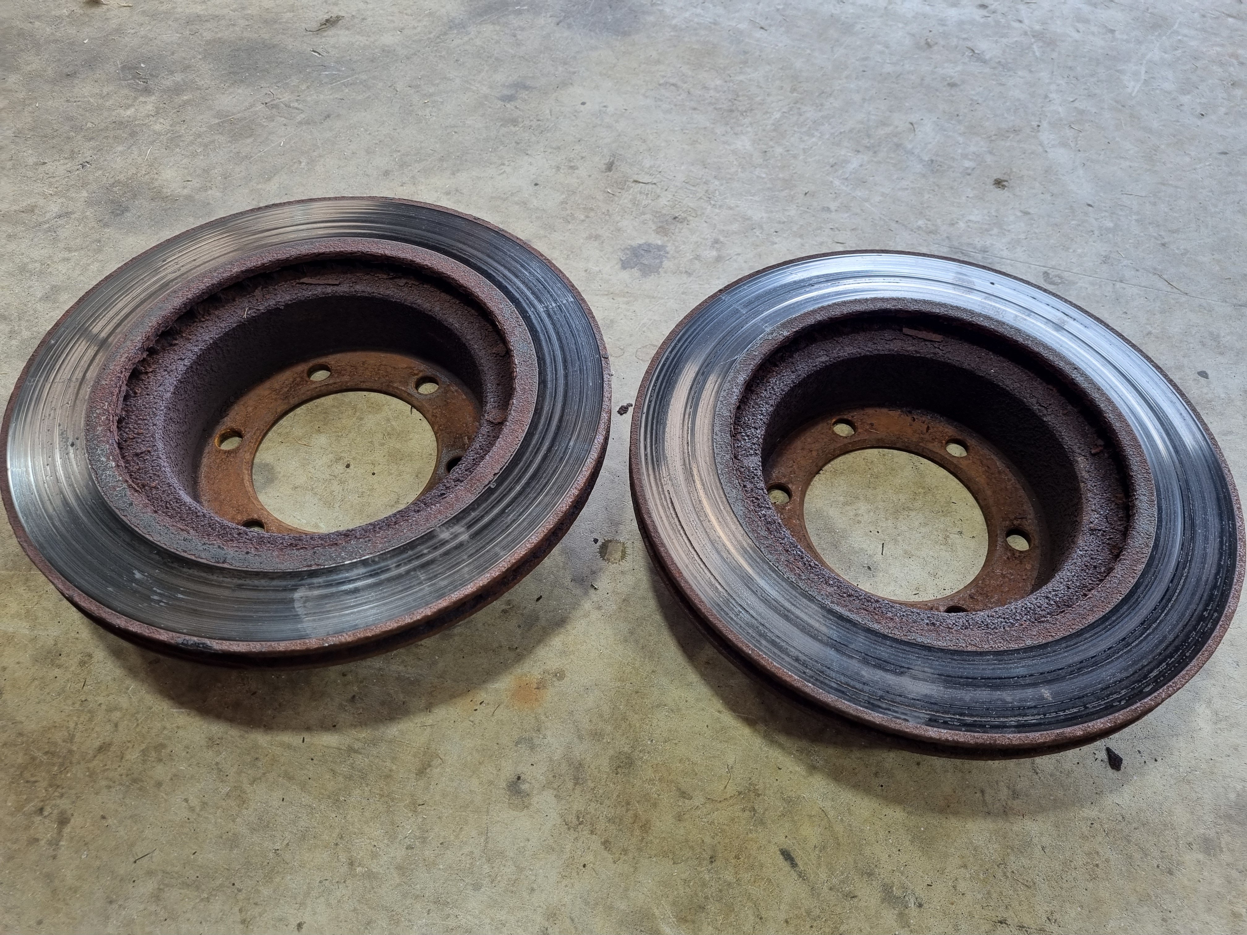
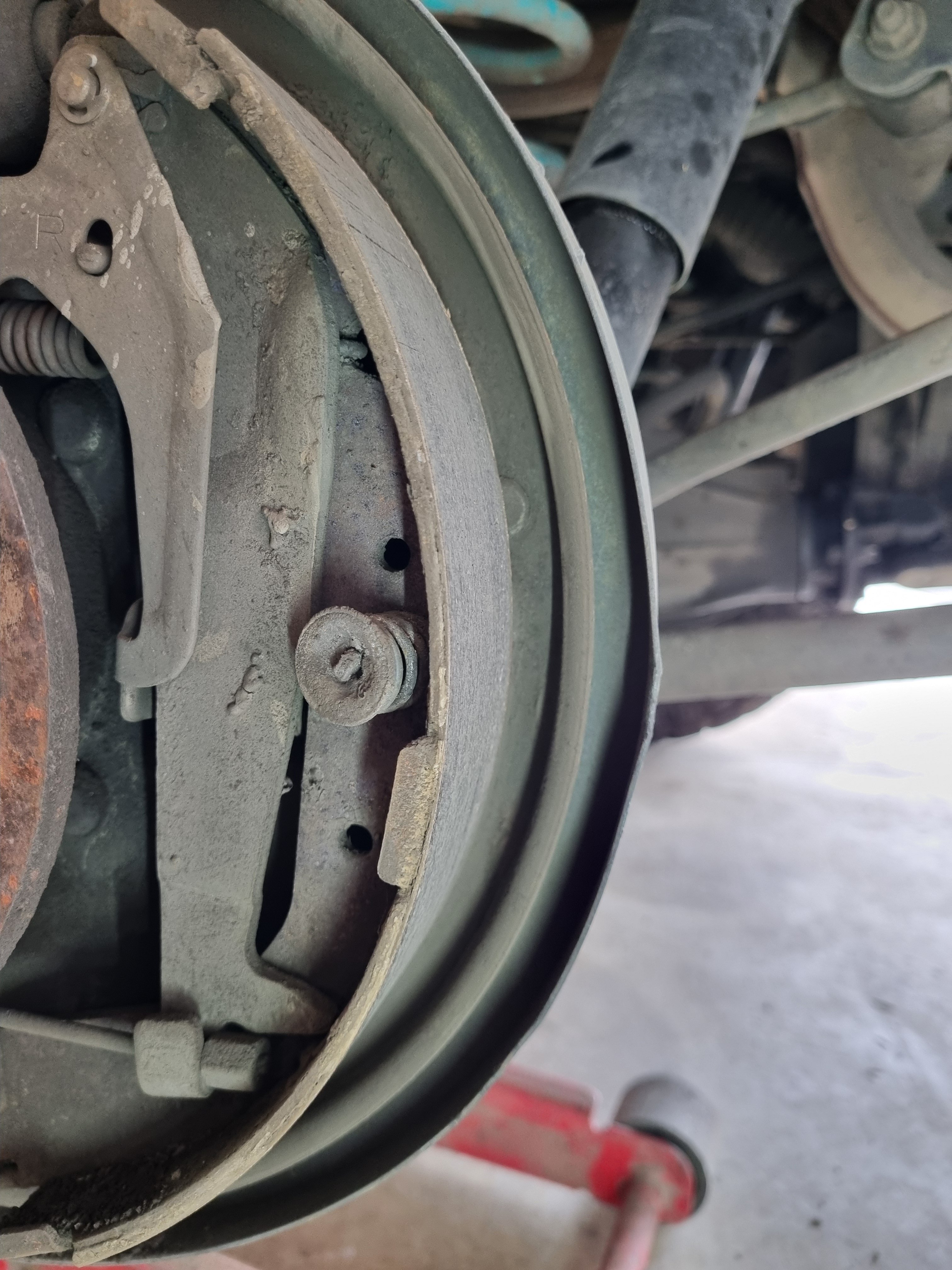
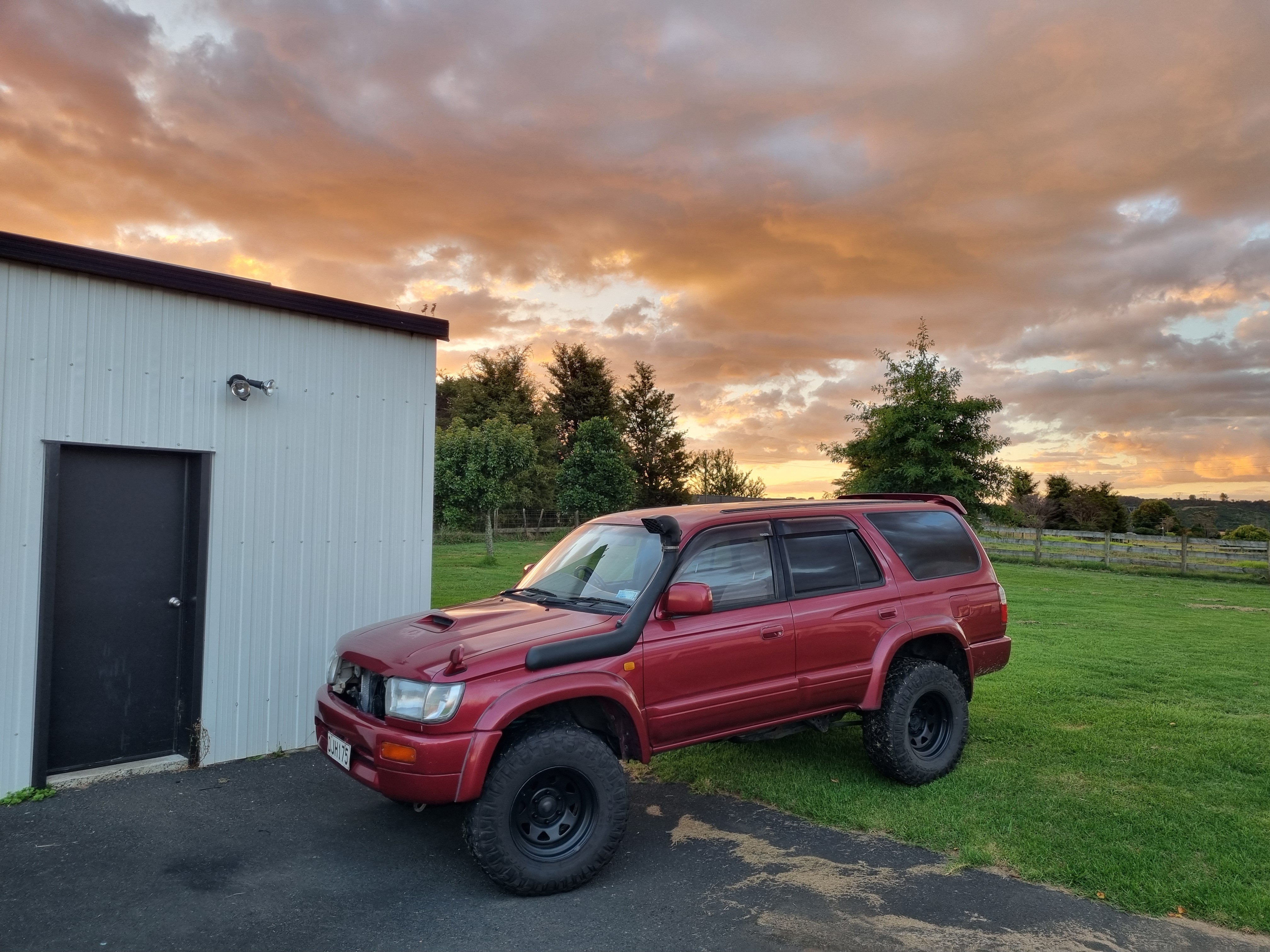
Nick recharged the AC system and now it works fucking ace. Couldn't feel my fingers by the time I got home so I'm calling that a win. Installation of new discs and drums. Front was easy, as you'd expect. Rear was a bit bit difficult to get the drum of due to the massive lip on the inside. However once I got the drum off I discovered the thinnest brake shoe I've ever seen. And of course the wheel cylinder was leaking so I'll get new bits next week and re- do the whole back brakes. Also I found the reason why I'm now the best 4wd driver in NZ. Auto disconnected sway bar for max flex bro. That's what the 4wd people say, you wouldn't understand.
14 points
-
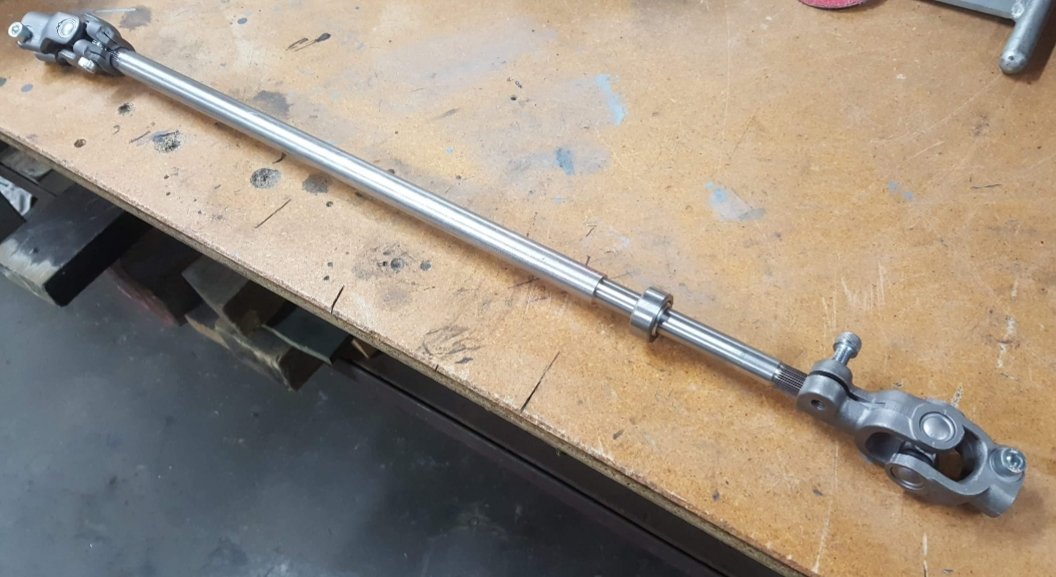
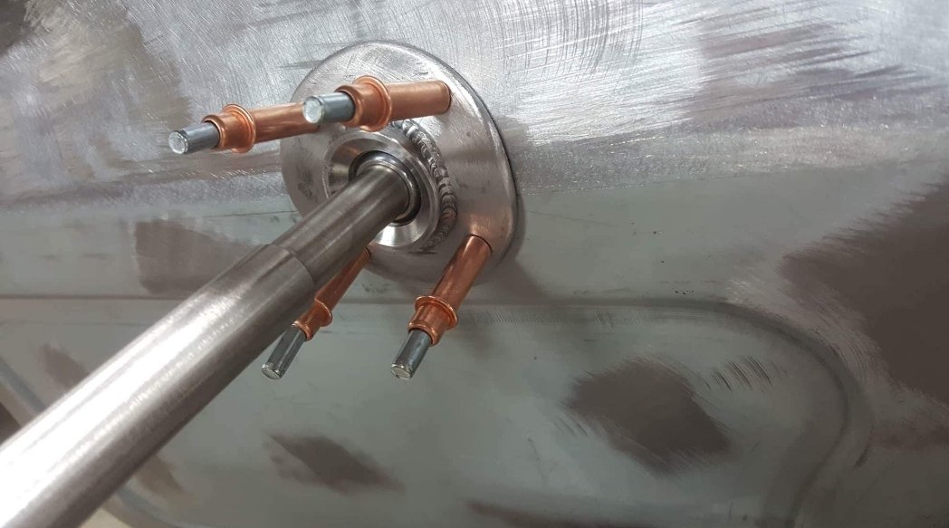
I glooped the two halves together, bolted them up, bolted the tailhousing on and let it set. Following morning it was bolted onto the engine, unsurprisingly a bit heftier with all the gubbins placed back within the box. Its about 9kg heavier than the standard imp box. I then started to fit the first part of the gearshift linkage. The first of those snazzy universal joints, handily available in a diameter to suit the shifter shaft on the Subaru box. I just needed to add a small locating hole for the grub screw... Universal in place.. Engine and box were then bolted back into the car. This bit is so quick and easy when using the 'engine stand 2000'. It takes about 10 mins and I'm getting quicker. It'll be slower when there's shift linkage to undo and driveshafts to slip out of the way. But at least the main heavy awkward part is actually easy. That lot in place I took some pics. Its neat to be able to look out from the one of the lounge room windows down onto the workshop floor and see this... With that lot in place I was able to suss out the angles I could get away with, as shallow as possible and allowing for the handbrake mechanism. I had this old imp gearstick assembly that @dmulally kindly posted over to me. Some previous owner of the car he got it from liked painting things. Everything. Multiple times... I scraped all the layers off, took it apart and cleaned off the dirty old grease. Discovered it had been cobbled together from two old shifter bases. It was originally a very early Imp unit when the very first cars had an automatic choke, which often proved problematic. Hillman then changed the cars over to a manual choke with a nifty little lever in front of the shifter. This mount had been added to the early base. Which means they must have chopped up a later baseplate to get the choke mount. Why they didn't just fit the entire newer base plate I don't know. But what I had in front of me was a frankenstein of base plates with barry spec welding and fixes, but also including a not too badly made bronze bush on the lever where there is normally a (wornout) plastic bush. I had a couple of shift rods to choose from. I chose the least worn. Moving back to the gearbox end I machined up some shaft ends from stainless bar to suit the universal joints. I had some stainless tube and welded the ends in place on the first shaft that runs from the gearbox universal down to the tunnel. Now I needed a sturdy, slippery support to mount in place of the second universal joint. This will not only take back and forth movement on the shaft but also a bit of thrust loading created by the angle on the connecting shaft. I had already bought a lump of slippery hard engineering plastic with this application in mind when I had ordered the plastic for the flywheel thrust bearing a while back. It was bright yellow. Luckily not seen under the car as it would clash with the blue paint. I put a hole in it and machined the outside down. Which also created a pile of pretty swarf.. Then reamed it out to 1" Still a bit tight so out with the adjustable reamers.. until it was just right... Then made a stainless cradle .. The cradle got some wings welded in place and I dug the rivnut tool out.. Mount now bolted in place in the tunnel I had to chop the last tube to the right length, weld on the end and bolt the universal in place.. The front end below the shifter was was standard imp stuff and this is where problems popped up to throw a medium sized spanner in my workings. The side to side gearstick movement across the gate was minimal. Ridiculously so. Like about 1". Or 25mm in new money. Yet the fore and aft movement was about right. But quite stiff. I was contemplating why this was so and what I could do to remedy this when I also noted that 1st gear was where 3rd was and 3rd was where 1st was. Poos. Four years ago when I had compared the Subaru gearshift pattern at the box to the imp unit I thought they were exactly the same. But I had not accounted for the reverse rotation taking place under the imp gearstick. Also I never really thought much about how little of rotation the Subaru box needed on its shifter shaft to shift the internal selector across the 3 rods. Its a tiny amount, like 3 degrees say. Whereas the Imp box has a shorter internal selector and requires more rotation at the shaft. Hence the Imps gearstick knob only moves a teeny bit when coupled to the Subaru box. But the Subaru box has a standard/similar amount of rod movement within (ie 1-2 and 3-4th) which was going to make things trickier to fix. Simple linkage/leverage multiplications that is easier to see than explain. Sorry if your brain hurts. I had to hurt my brain a little bit to suss out a solution but there was only a little bit of smoke. The reason the scooby box is different becomes obvious when you see the scooby shifter setup. Which luckily I can show you because last week thanks to @Leone I was put onto a local fella to me who happens to have many old Leones and Brats kicking about his property and he had a spare leone front wheel drive box that I wanted (always handy just in case...) His property is amazing!!! Long 4wd only driveway up to a ridgetop house with stunning views out over Tasman Bay. Old leones just kicking about... Luckily we have our trusty old 4wd Hiace and that became the days gearbox transporter... Box on bench. Look at that shifter mechanism... The shifter rod attached to the gearstick only rotates a tiny amount when the stick is moved sideways across the gate. But the rod moves 10mm in each direction when shifting for and aft. Simple. Robust. Very Subaru. I can't copy it though because I have turned my box 180 degrees. No matter where I put my pivot point (below or above) I'll have one of the planes working backwards. So I decided to build a new shifter base setup. The most important thing was to reverse the rotation so the gearstick pattern is correct. The imp pivot point needed raising to allow the offset shaft end to be rotated to above rather than below the centre line, so reversing the across gate movement. I would add the ability to adjust both rotation and lineal movement. Started with a new pivot cup because I was not happy with the worn and Barried pressed steel item.. I dug out a large lump of steel bar... Chopped out a square and cleaned it up in the mill.. Big drill = big hole.. Rough machined out a cup shape. Cut a form in cardboard to suit the brass ball and used a die grinder bit to finish the shape... Grinding paste time... Slots for pivot pin.. Lightened the lump down.. Built the shaft up with weld and machined it down so I could add a lower pivot point. Milled some steel like so.. Welded a boss on.. New socket for shift lever ball end... Cut out Barrys previous workmanship... Machined up some spacers and a base plate.. Welded up a little tower (my stainless and steel tig welding is definitely improving, helped muchly by realising that not being able to see what I'm doing does not help much and finally admitting to my age and buying some reading glasses....) Welded tower to base.. Now all together please... Bolted together. You can spot the adjustable rotation, which the spacers allow for, along with adjustable pivot point. In place... Yay- it works! The shift pattern is correct and the action is much smoother. The spring loaded indents on the internal gearbox shift rods are quite stiff, which I noted was the same on the other box with its stock shifter. Its a bit baulky to push past the synchro baulk rings into gear but I think will feel better when the gears are actually rotating. There's certainly no slop in the system and it feels very mechanical - not rubbery. I now note how much flex there is around the shifter base in the imps tunnel (granted a very rusty shell..) Its something I might just try to stiffen up on my blue Imp when fitting this lot in. Phew. That was a little mini engineering mission I was not expecting but that's this project in general13 points
-
Well its a month later and I am getting back on form, hence this effort today; Plenty of room to finish off the wiring now. There was a minor mishap during engagements, now I need to figure out which Fiat Uno that distributor is off. I'll give the donk a clean up, new oils and filter, new plugs etc. Might drop the sump to see the state of play. For some reason it has way more oil than it actually needs, not sure why.11 points
-
10 points
-
5 points
-
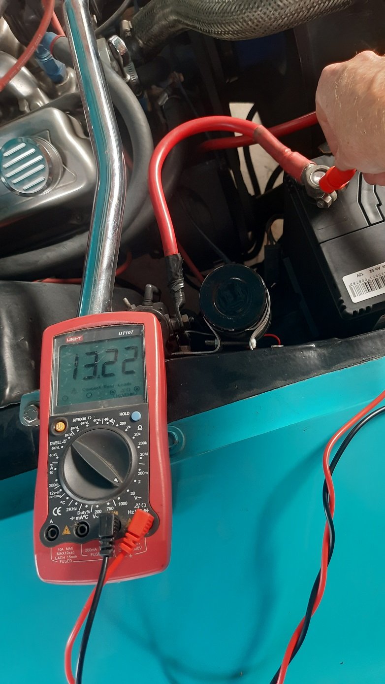
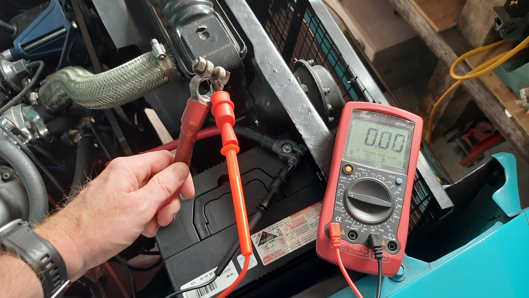
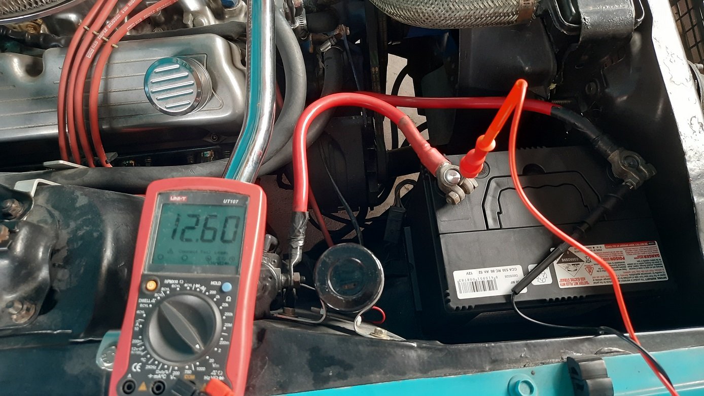
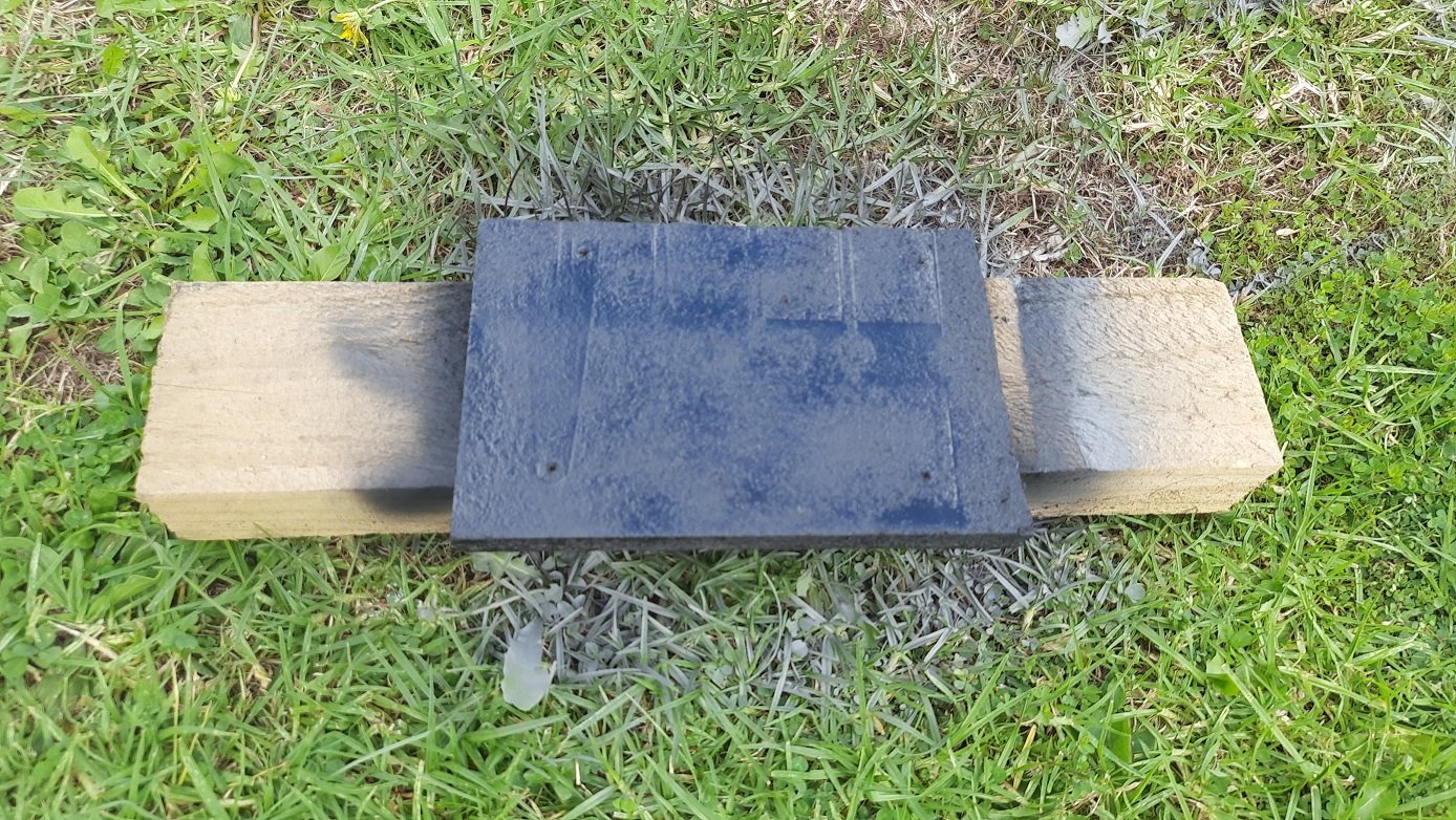
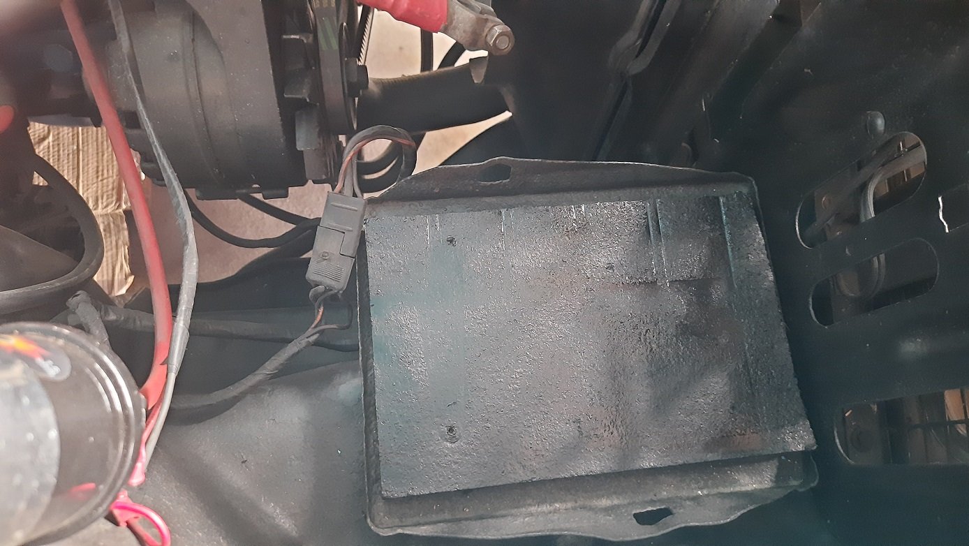
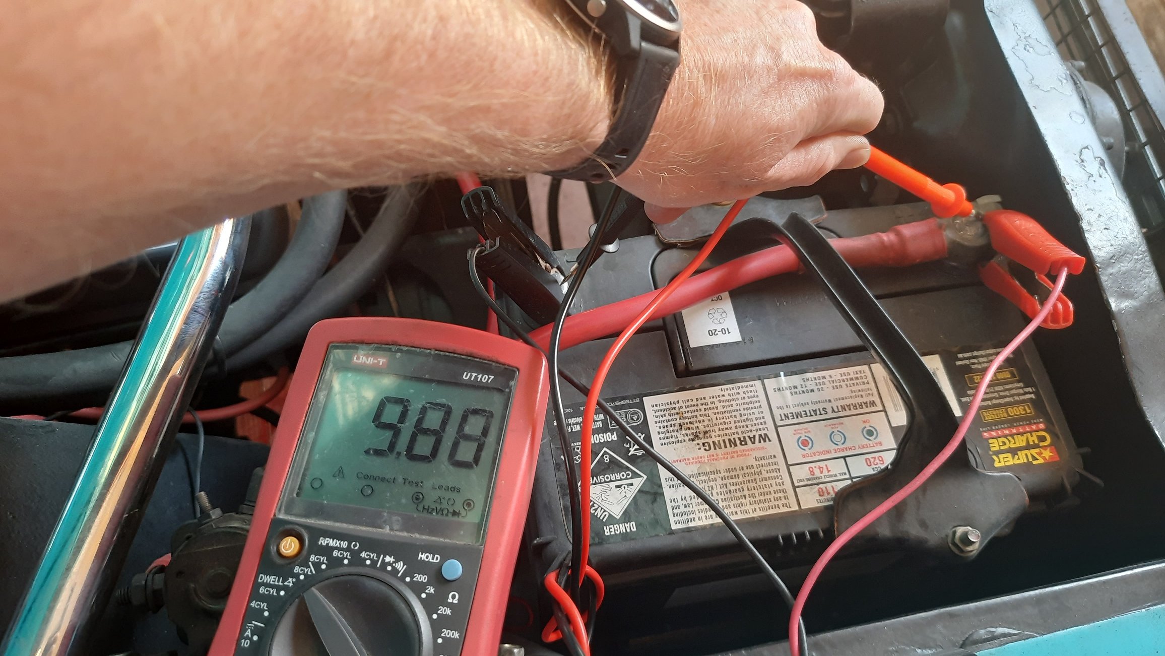
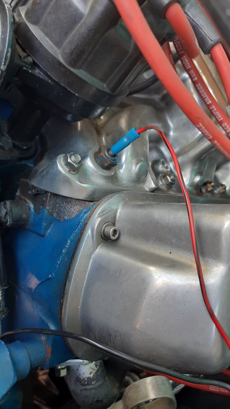
Went to Repco and got a new battery. Then went back to Repco to get the correct battery, (Repco branded) Century 68MF if anyone is interested. Threw it in and checked current draw. None. All good. Hooked it up and checked the voltage again, 12.6VDC, still good. thought it was sitting a little low and then remembered the battery spacer that was in it. High tech piece of particle board. Thought it could use a coat of paint. Looks like it was meant to be there. Last check was to fire it up and check the charge voltage. If it wasn't leakage current running it flat I needed to make sure the charge was within limits 13.2VDC at idle just after start, not too bad, needed a bit of a rev to see if it would come up to 14Vish. Got to 14V, then 15V then nearly 16V. Guess I know why the battery was toast. Guess I'll look at a new (internally regulated) alternator.
4 points
-
4 points
-
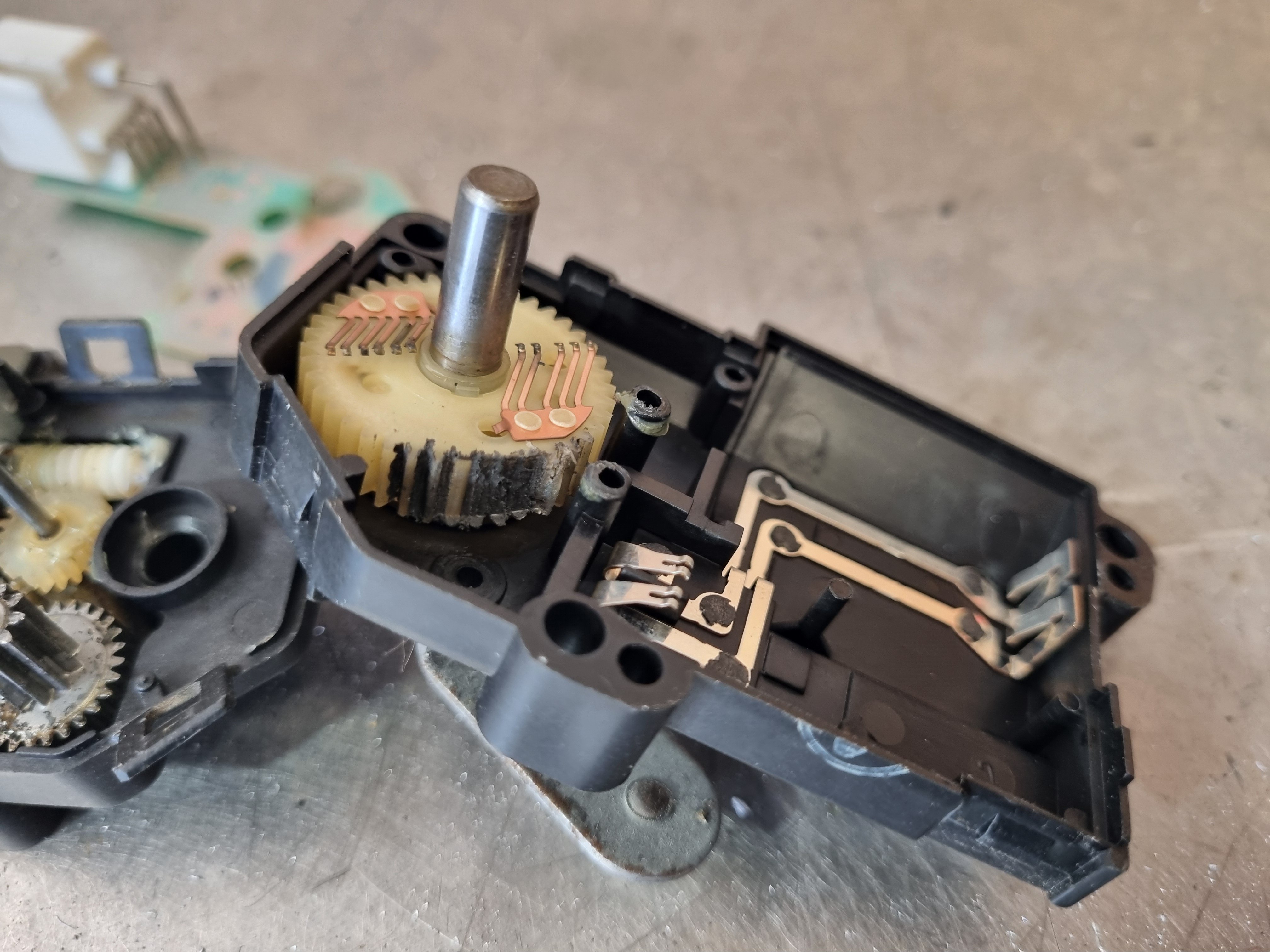
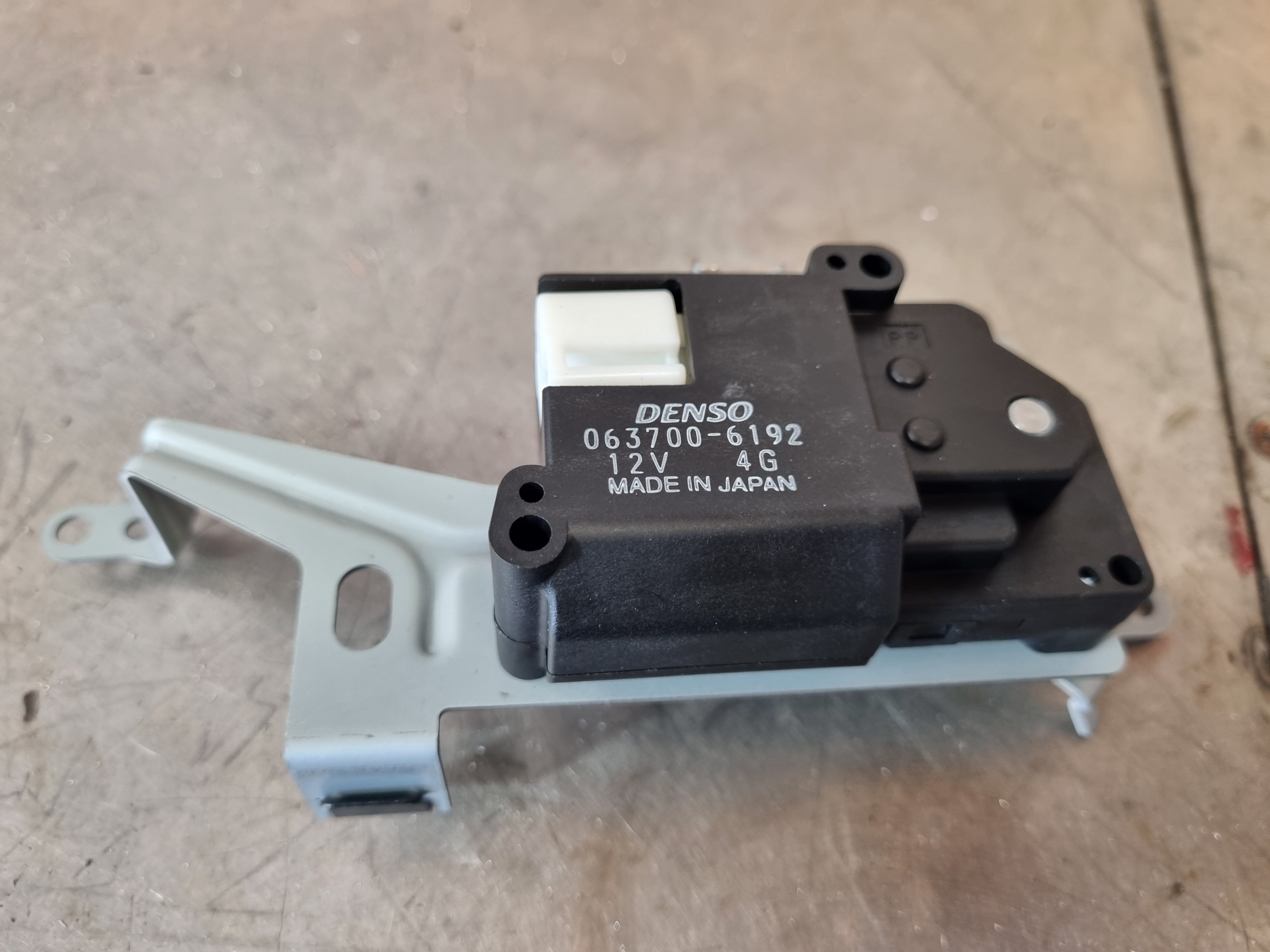
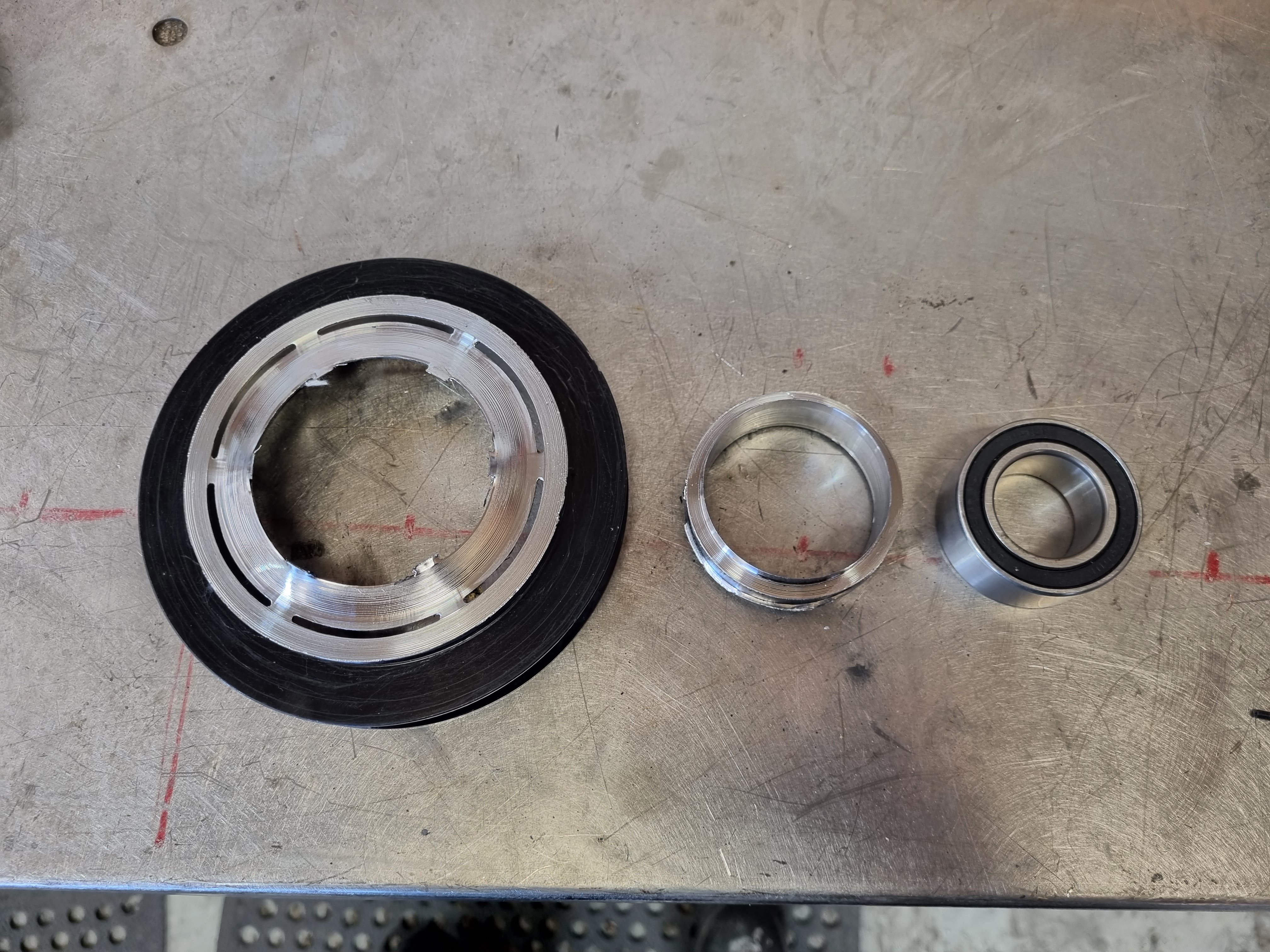
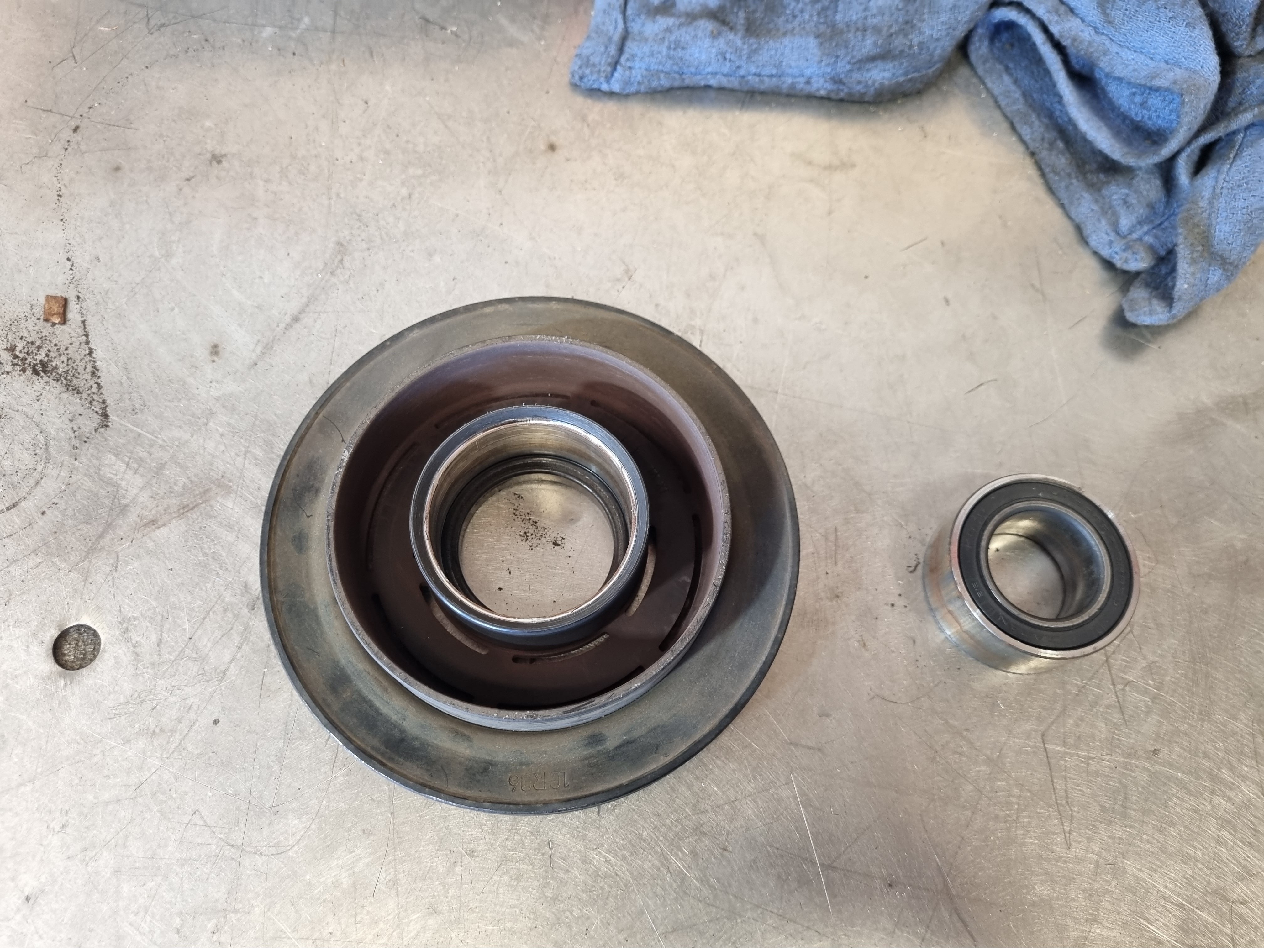
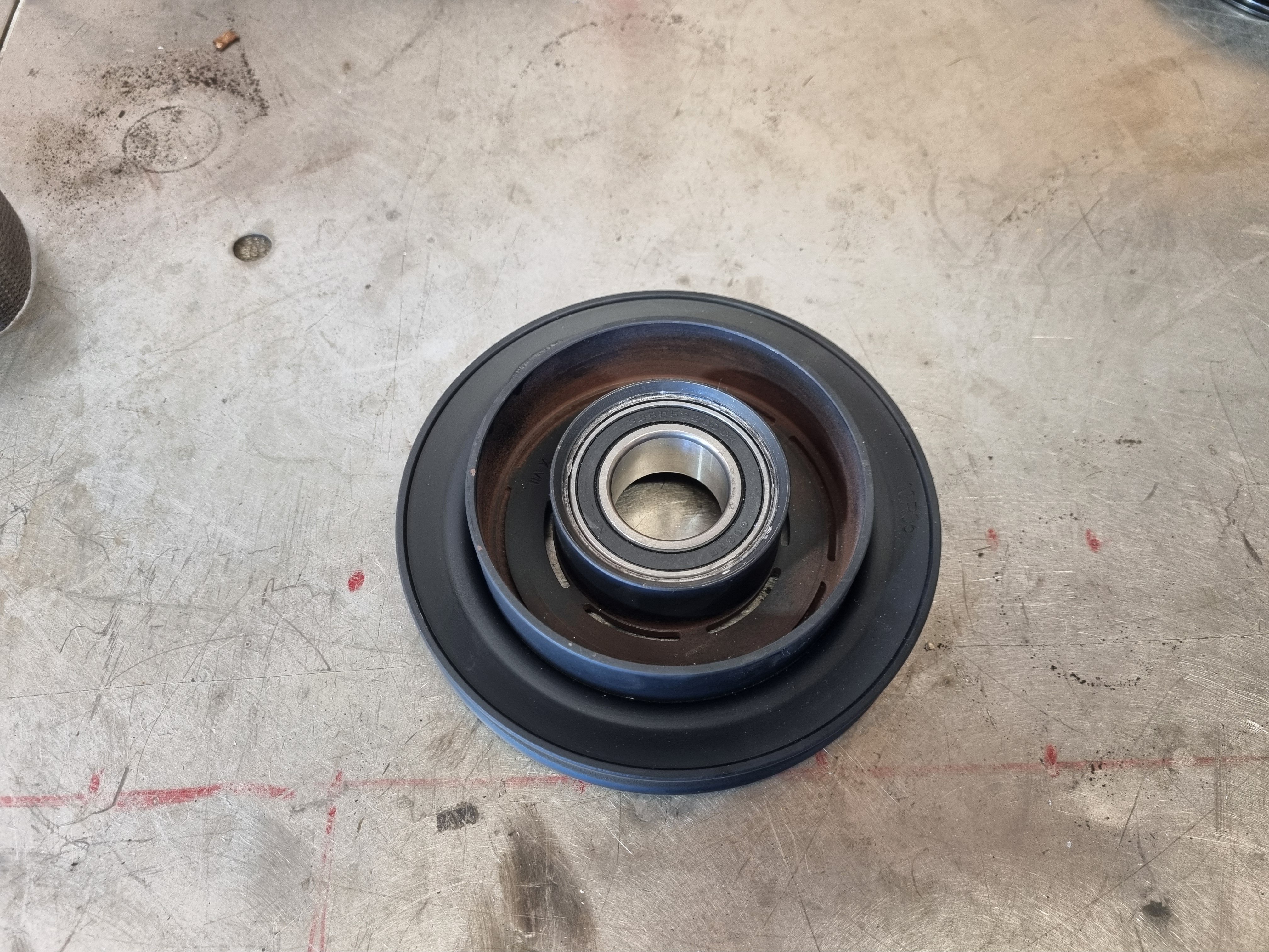
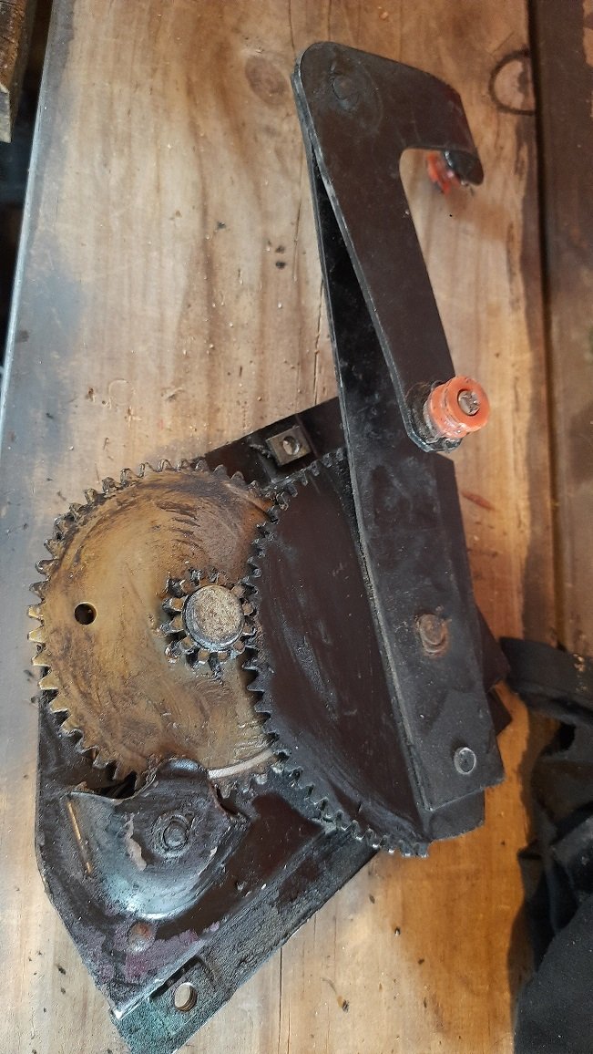
I'm a bloody farmer now you fucking ignoramus. Anywho, The heater drive motor has stripped a gear and thanks to the Nicksparky I got a new drive motor. Also the AC compressor I ordered had the wrong pulley on it so I had to swap the new bearing into the old pulley. I didn't want to smash the new bearing with a hammer so I machined the pulley away from the outside of it. Once I got the old bearing out I chucked some metal glue on the new bearing and pushed it into the old pulley. Jobs a goodin
4 points
-
All of which I have on order.4 points
-
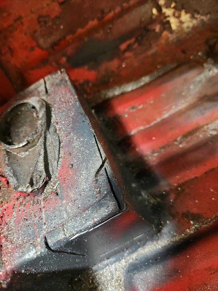
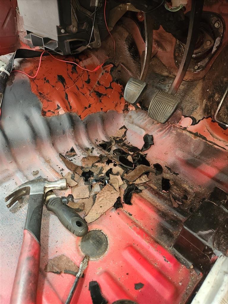
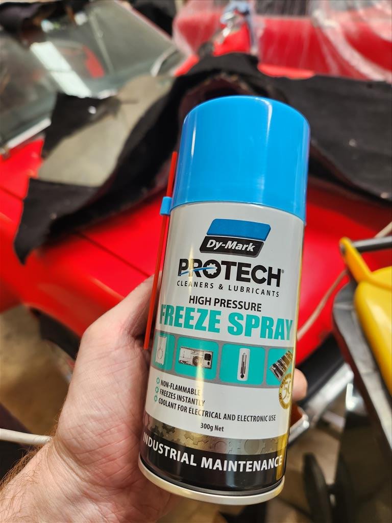
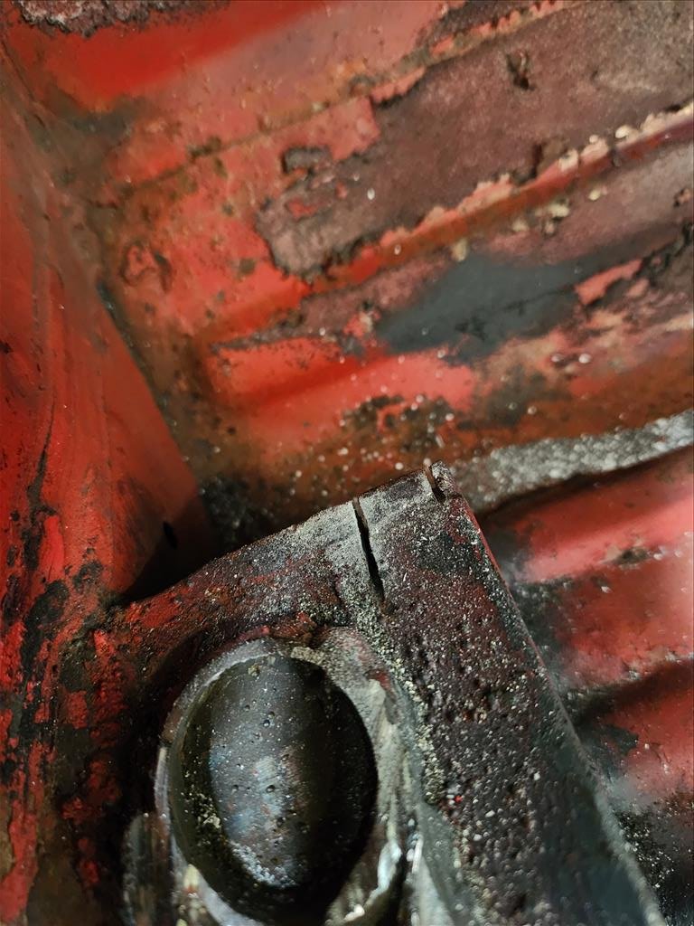
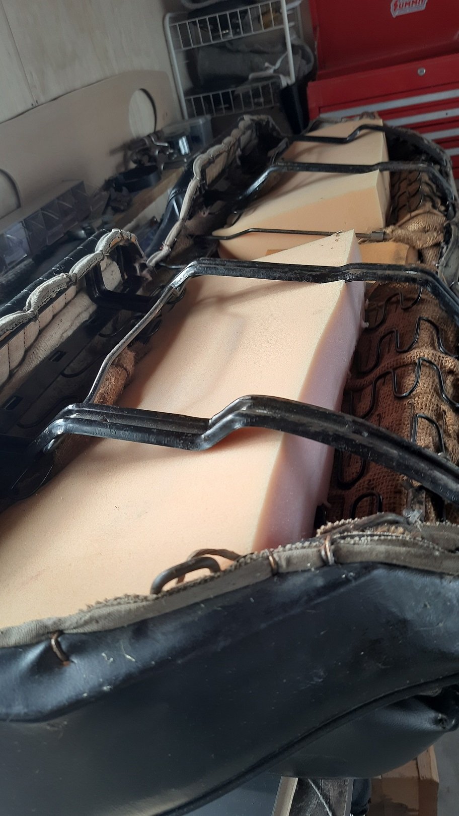
I picked up a saw during the week and had a go at cutting, didn't get very far before the blade decided to become smooth and basically just polish things. Smoke fell out of it too. So today I learnt there are different blades for cutting different thickness of metal. I've now spent my life savings again to buy a bunch of blades for chonker steel. If that doesn't work then I give up and will just get new carpet and cut around these stupid boxes. I did conduct a somewhat successful experiment with sound deadening though. I was reading about how to remove sound deadening without dry ice and this freeze spray stuff came up a few times so I gave it a shot. It didn't work too bad but it would be a ludicriously expensive way to actually remove large portions of sound deadening. Just getting the chips of this little bit used up the whole can. I haven't really worked out where the cuts for these boxes will be done but hopefully when I start to cut things it will make more sense depending on what access becomes available.
3 points
-
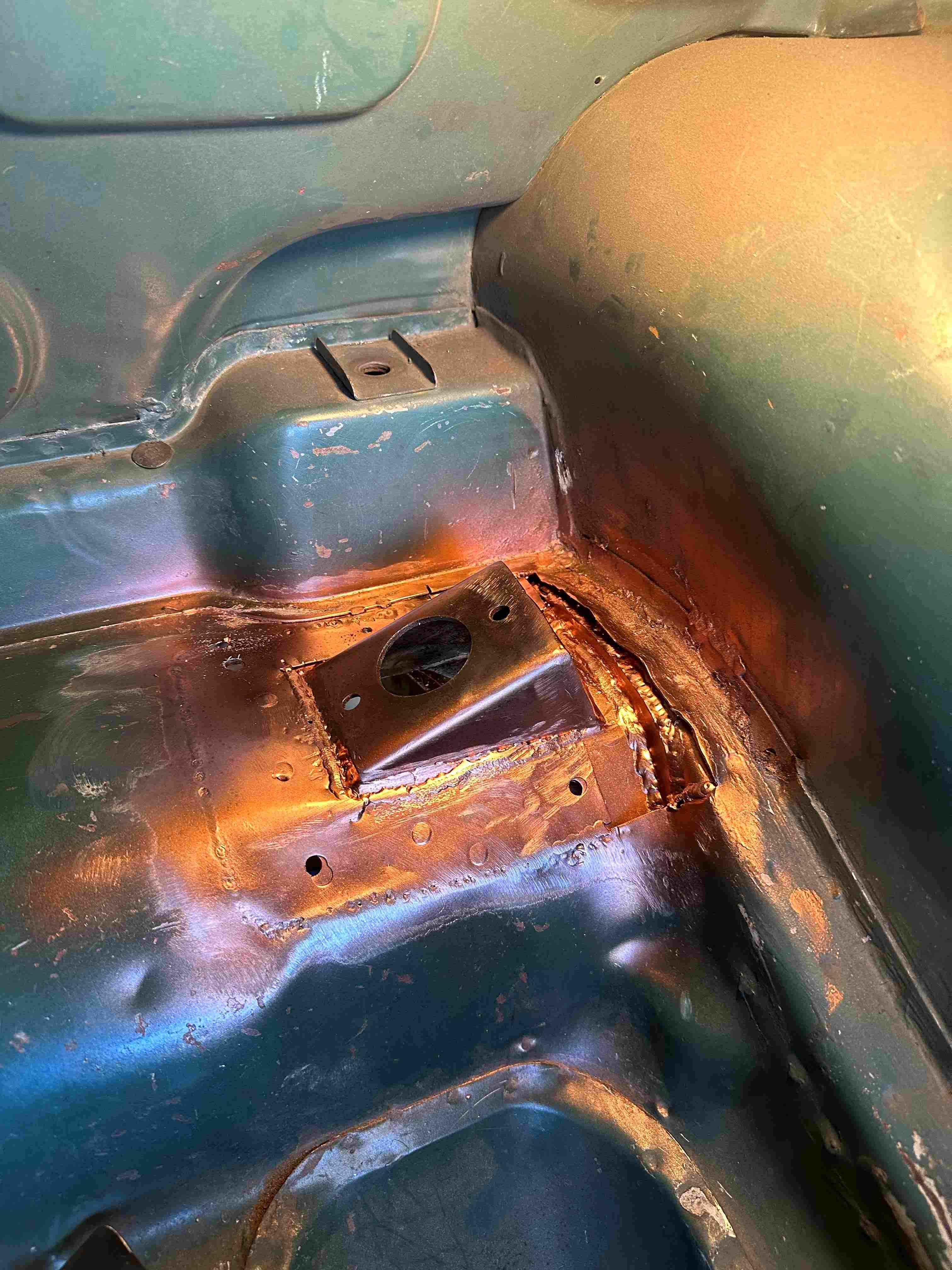
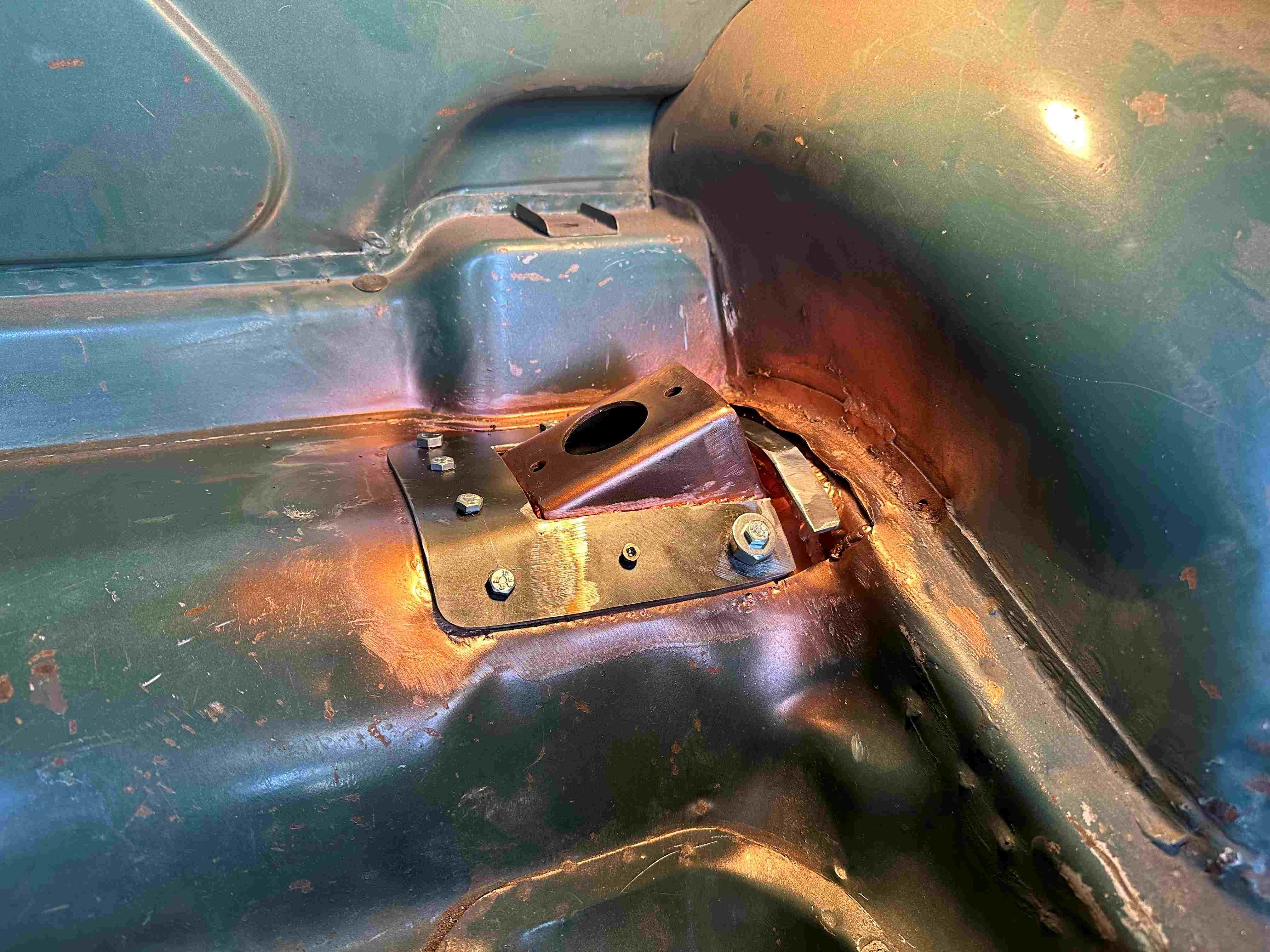
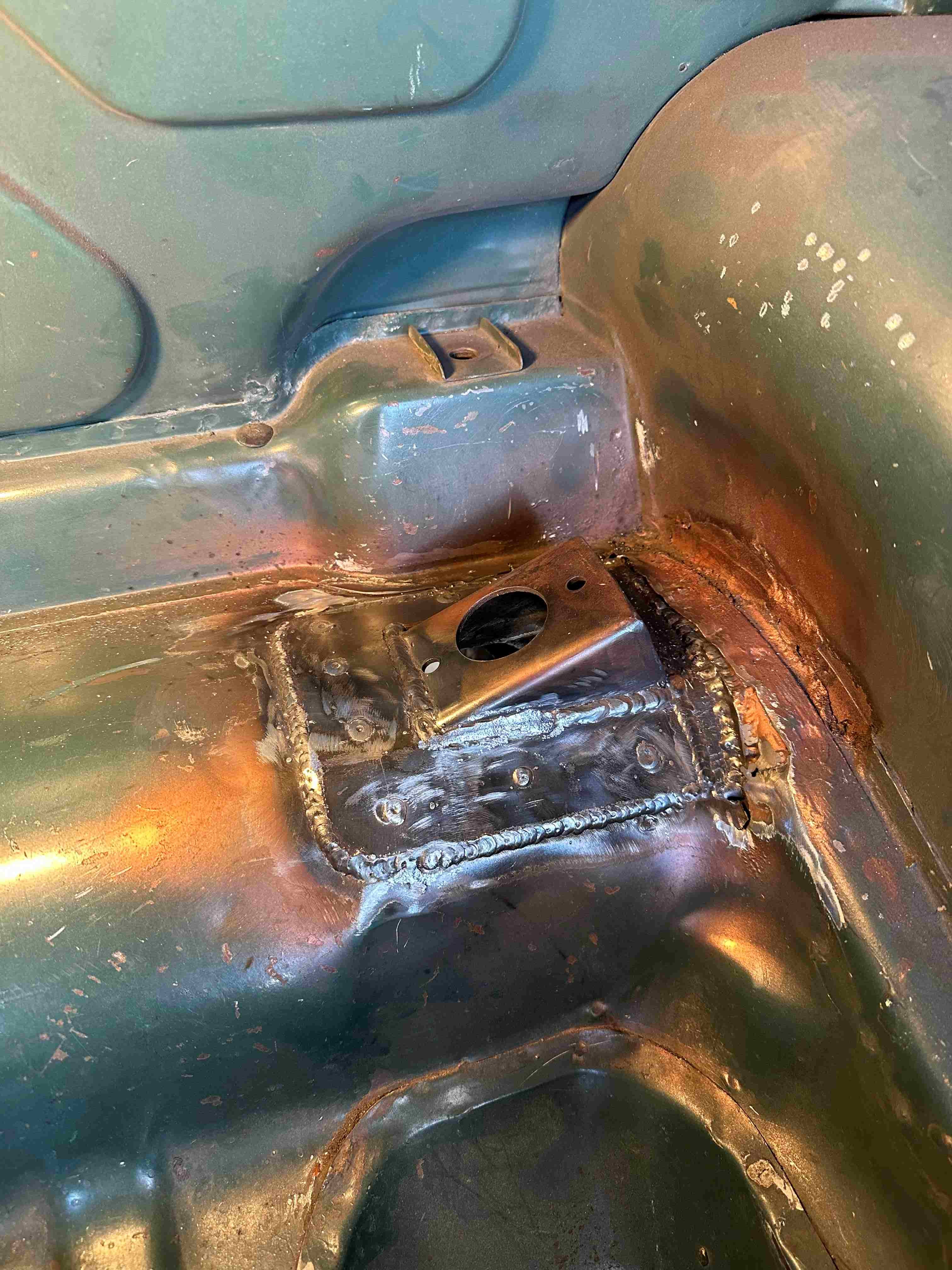
I managed to get the driver side welded in. Man, that took some time. By the time I clamped it in place (the easy bit) then put the 4 bolts in to hold it to the boots sheet metal. Then used some metal screws in between the bolts to hold the sheet metal to the shock mount. Then welded the bracket to the boot floor and the chassis fish plate. Once that was welded in I had to fit and weld the top plate which sandwiches the boot floor between the two. I made the top plate a little smaller in size so when I welded it, I was welding to the weld and bottom plate so I could use a bit more heat. Same procedure with bolts and screws and then welded it in. Welding went well really (well I think), though not that easy being folded in two inside the boot for some of it. Should have taken the pic before I sprayed on the weld through.
3 points
-
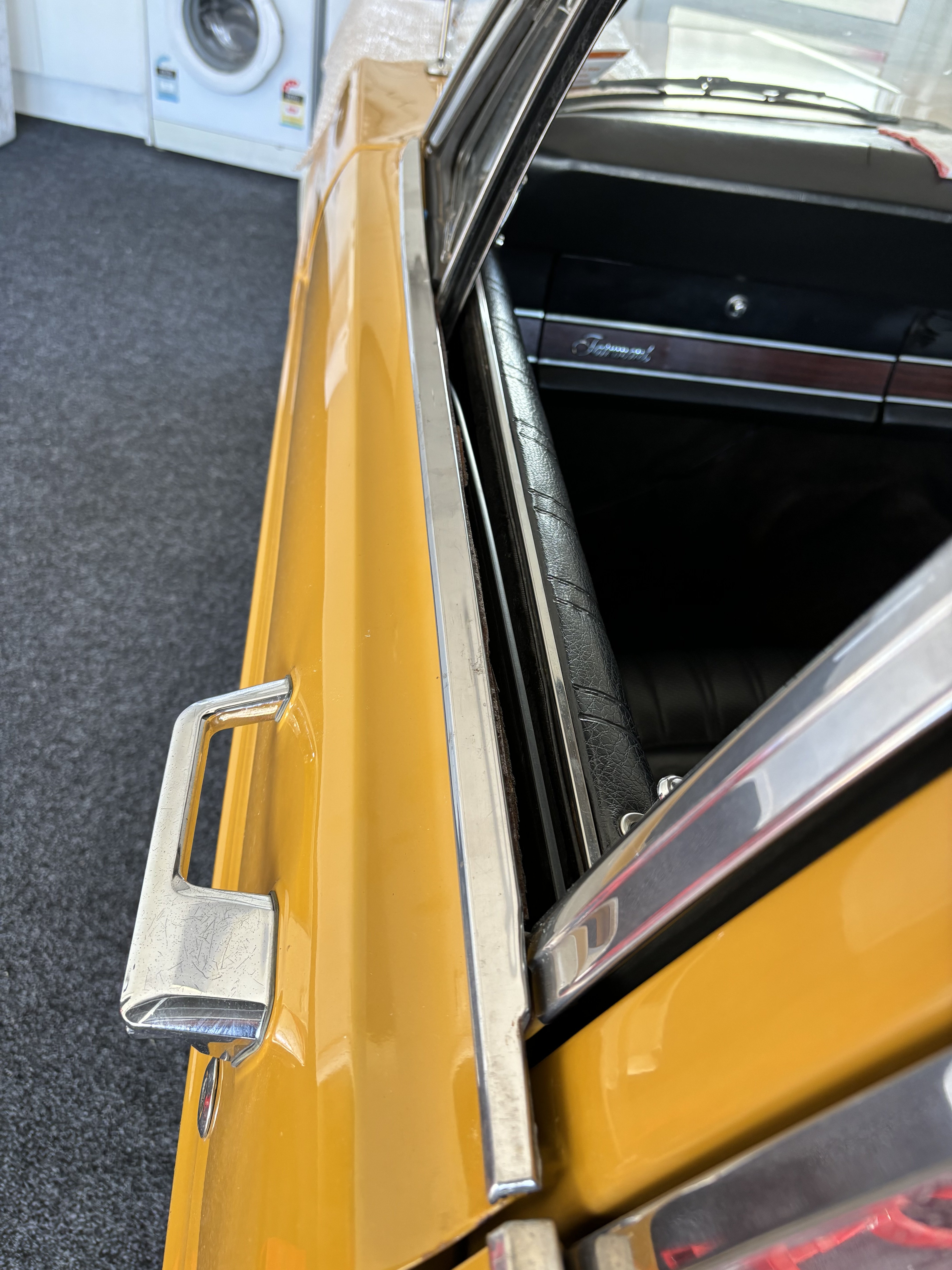
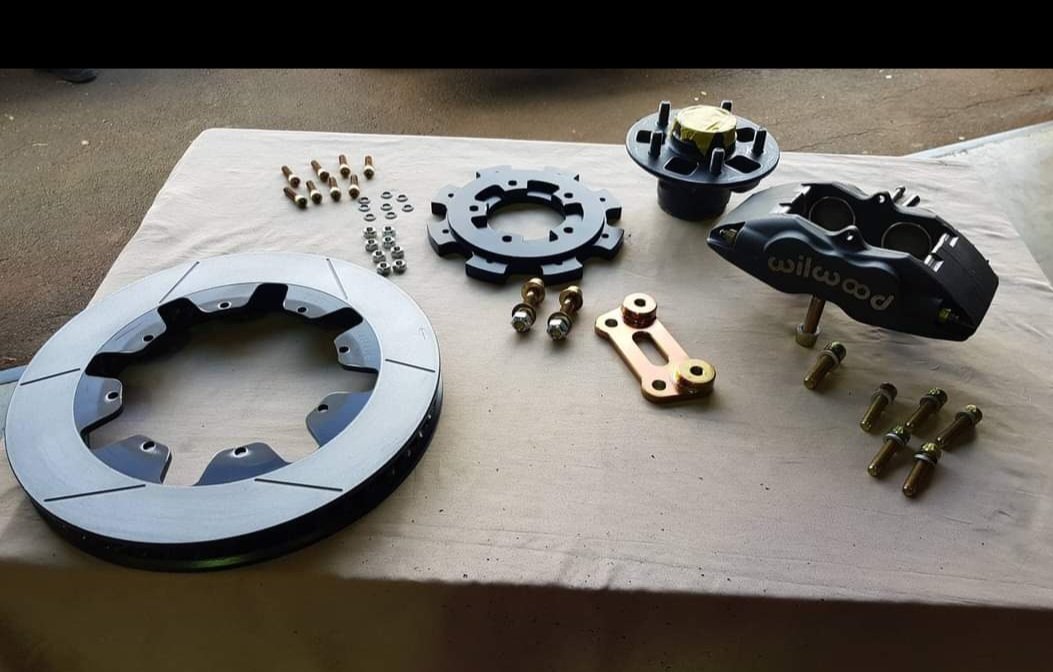
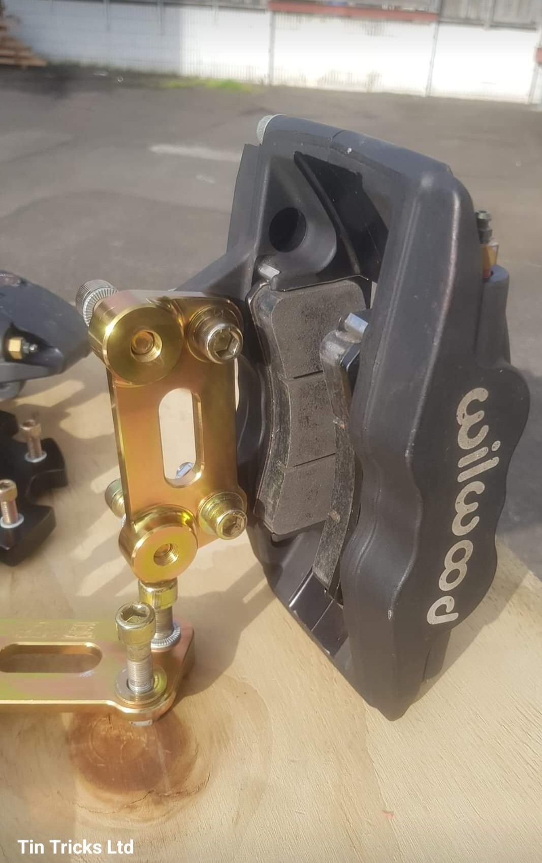
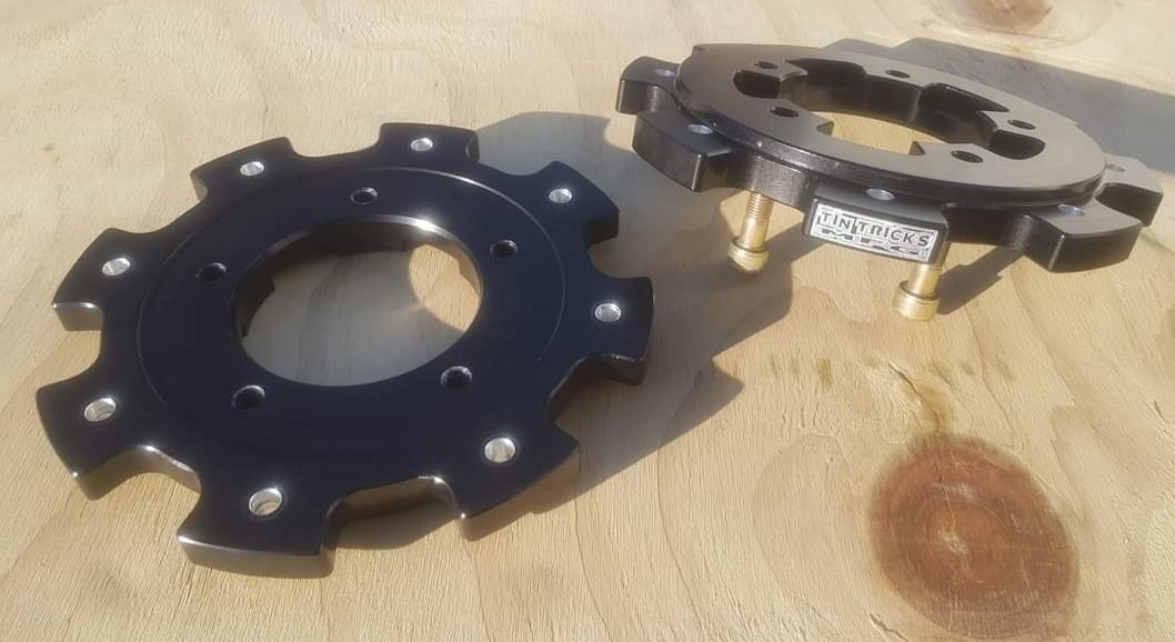
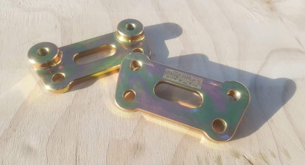
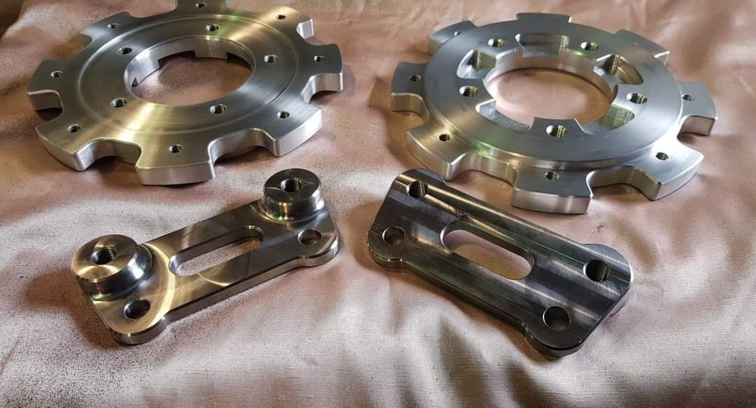
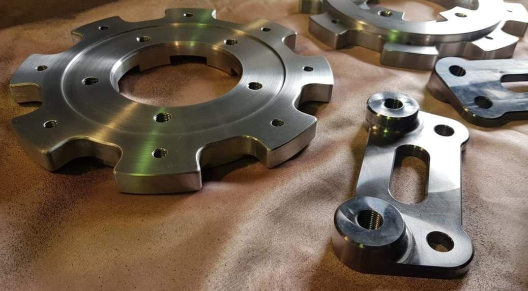
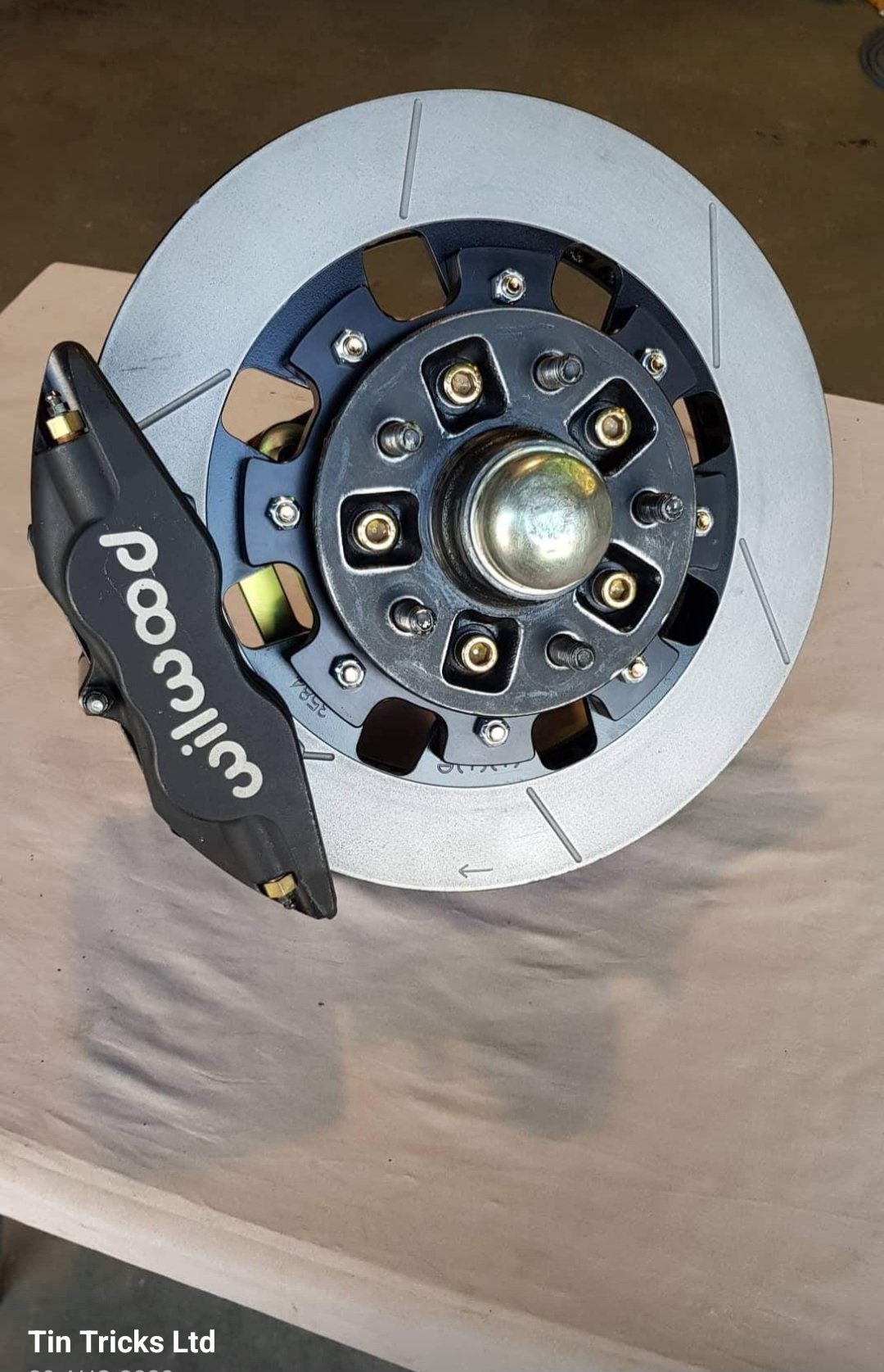
"The front TinTricksMfg bracketry kits for '85-'00 2wd Hilux hubs consist of... ▪︎2x billet 6061-t6 anodized alloy hats ▪︎2x billet p20 zinc plated steel brackets ▪︎complete zinc plated fastener pack to suit -The billet 6061-t6 hats are a hubcentric, bolt on adaptor that mount to the back side of hub the same as the oem rotor would. The rotor is also located centrally to the hat by the lip machined in on back side. 8x 5/16" fasteners attach the rotor to the hat. The hats are anodized for corrosion protection. -The billet p20 steel caliper brackets adapt the aftermarket caliper to the oem spindle caliper mounts. Ease of fitment & fastener/tool access has been kept in mind with bracket design. The brackets are zinc plated for corrosion protection. -Fasteners used are suited to a high-heat environment. Grade 12.9 cap screws zinc plated and post heat-treated. Hardened flat washers with Nordlock & Schnorr locking washers plus zinc plated cone-lock nuts. These kits are built to comply with New Zealands LVV Braking & Attachment Systems Certification standards and discussions with our local certifier were had throughout the design process. They are 100% bolt on with the oem hubs, and are made to work with oem or drop-spindles. (Minor variations may apply between spindles/castings) >>Note: kits suit 17" wheels upwards. I will confirm caliper clearance via private message. ALL PRICING IS IN NEW ZEALAND DOLLARS AND INCLUDES GST. OPTION 1 >>Hat, Bracket & fastener kit only (both sides) $1300.00 with natural/clear anodized hats $1335.00 with black/colour anodized hats (Minimum run of 10 hats needed for bulk anodizing prices otherwise a one-off charge applies) OPTION 2: >>Complete kit with Rotors, Calipers, Brackets & fasteners. (excludes brake pads)(both sides) $3085.00 with natural/clear anodized hats $3120.00 with black/colour anodized hats (Minimum run of 10 hats needed for bulk anodizing prices otherwise a one-off charge applies) -Rotors are Wilwood 13.06"x1.374" (331x34mm) Gt48 curved vane slotted & vented. P/n: 160-3584c (Right) & 160-3585c (Left) -Calipers are Wilwood 4-piston Superlite forged type. 1.75"x1.10". P/n: 120-11135 (Note: extras you will need to buy are brake pads with a compound to suit your requirement, plus brake hoses/fittings.) * Copied over from Matt's business page2 points
-
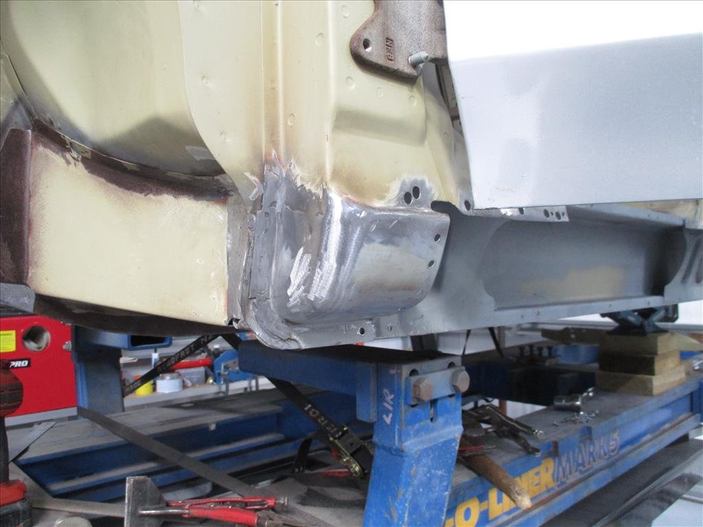
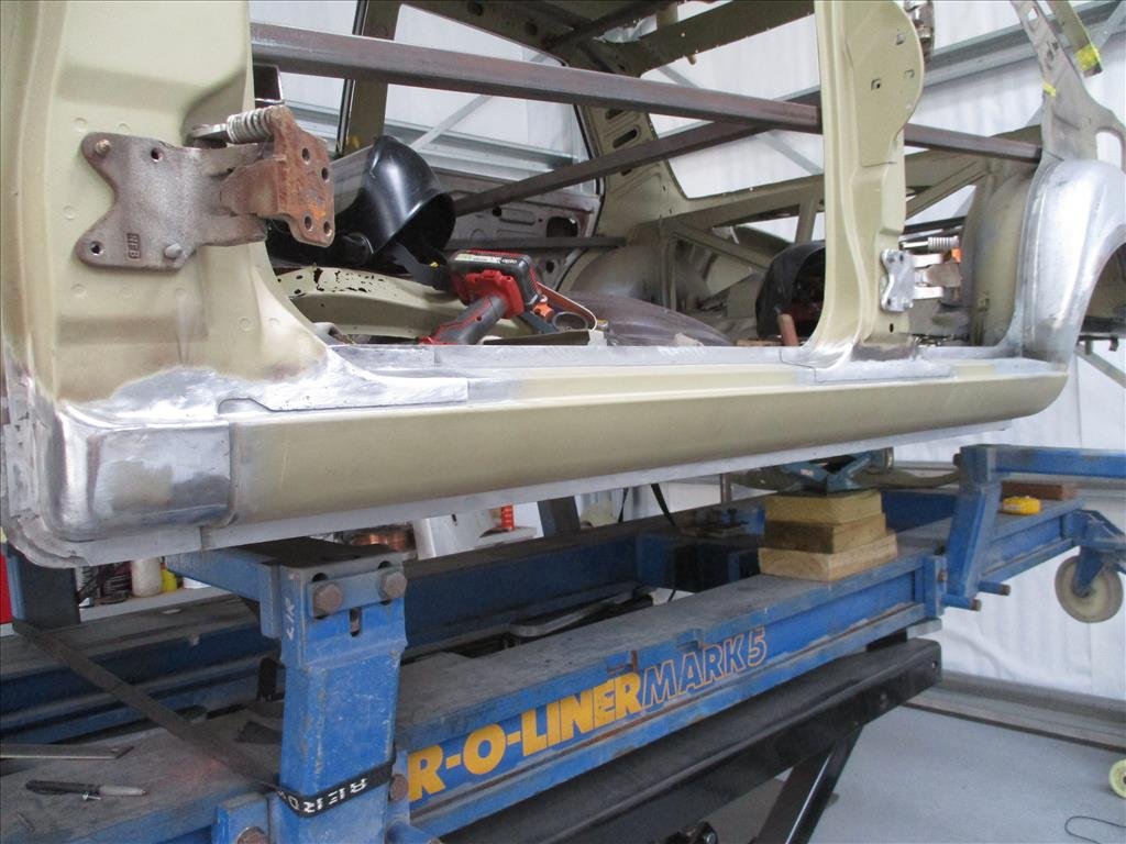
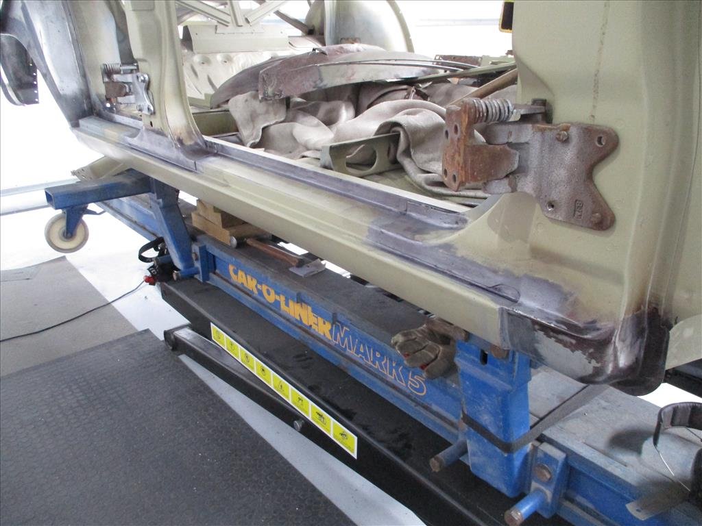
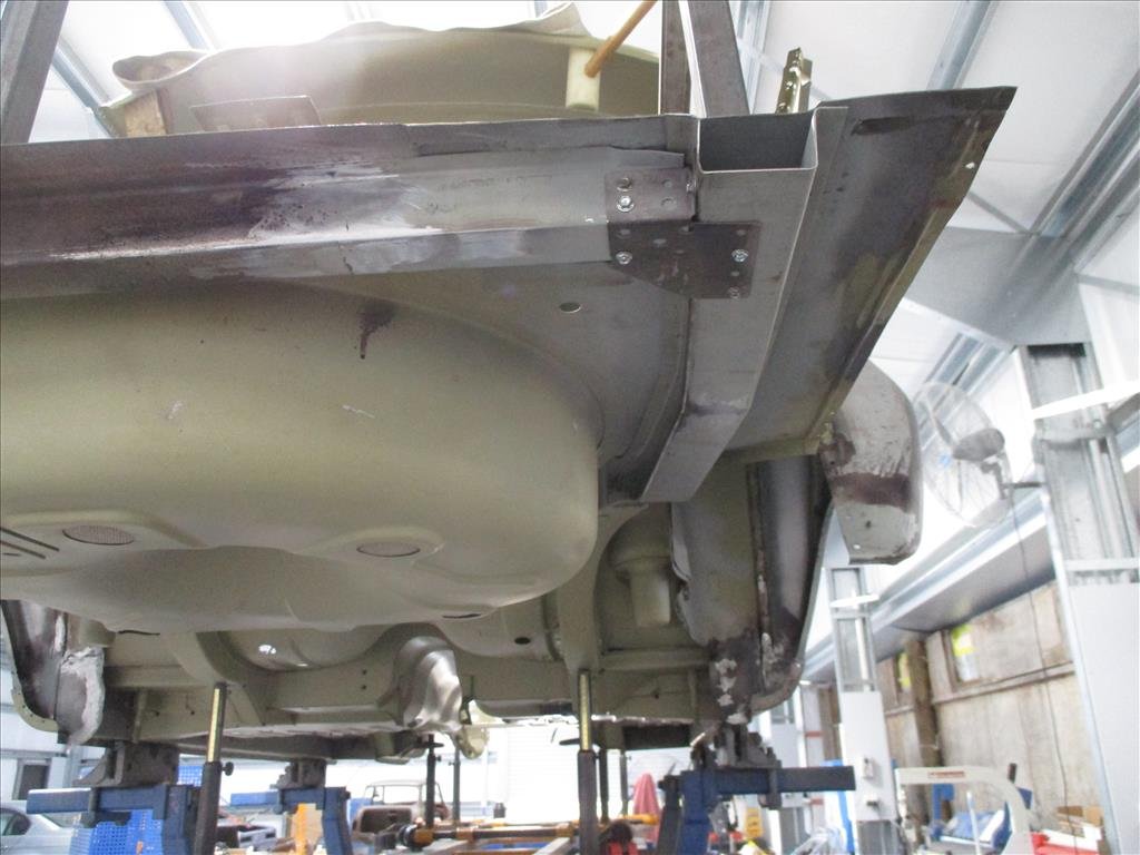
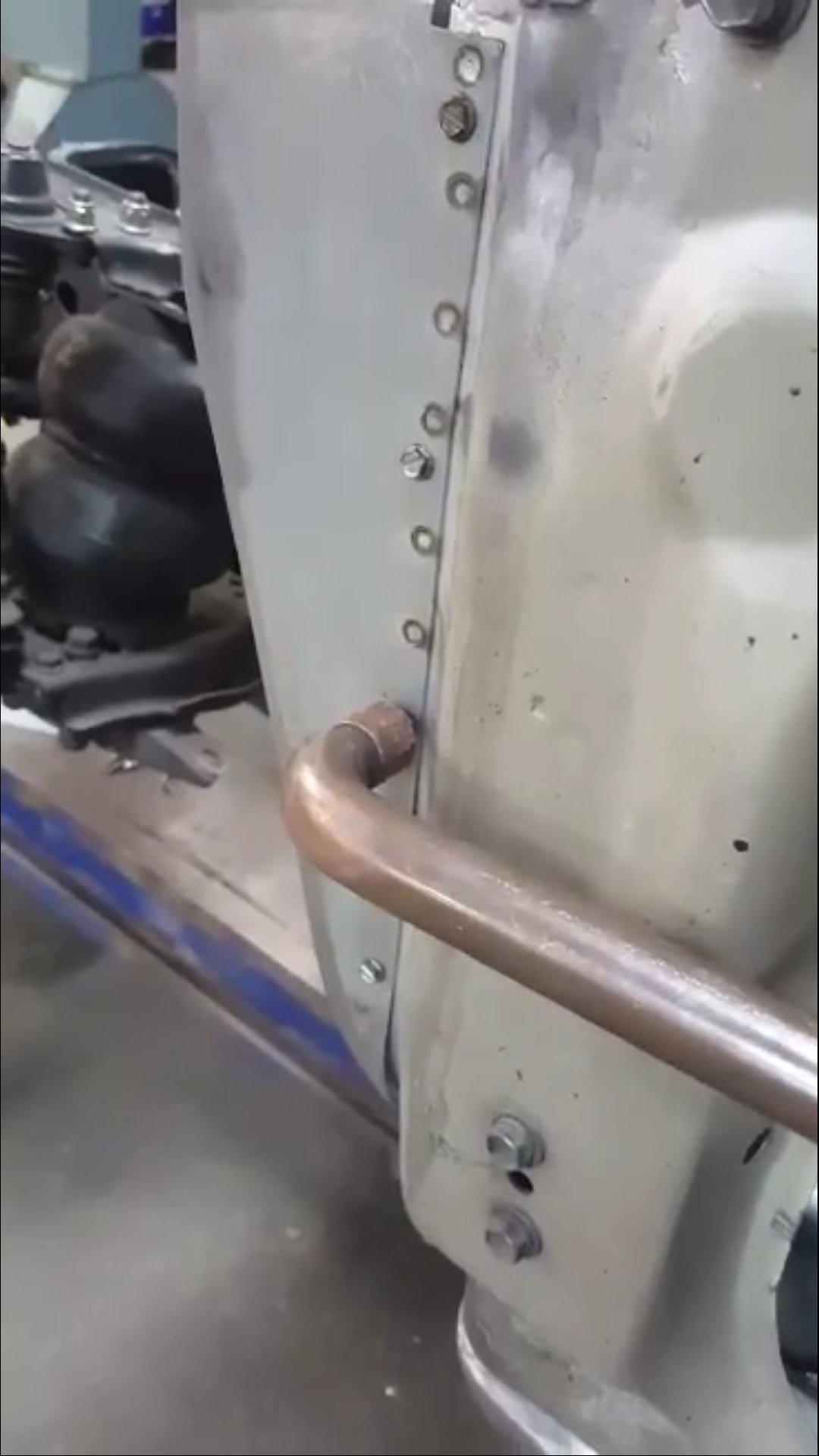
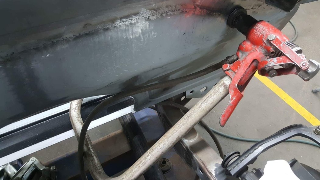
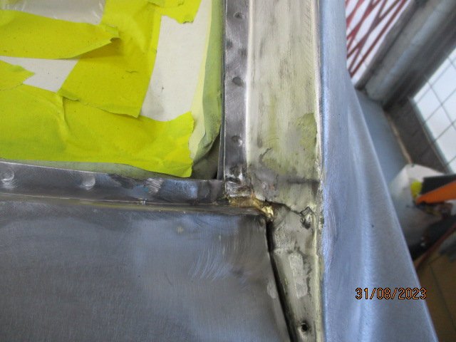
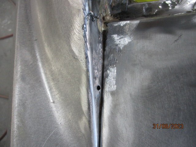
Another email from panel Barry come through recently. He's been spending time cleaning up the sills and preparing for the final weld in as well as getting all the welds in the rear floor/boot area ready to support the rear end going back together.
2 points
-
lol sheepers spends 5 mins in south auckland...2 points
-
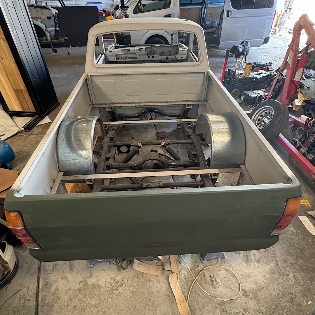
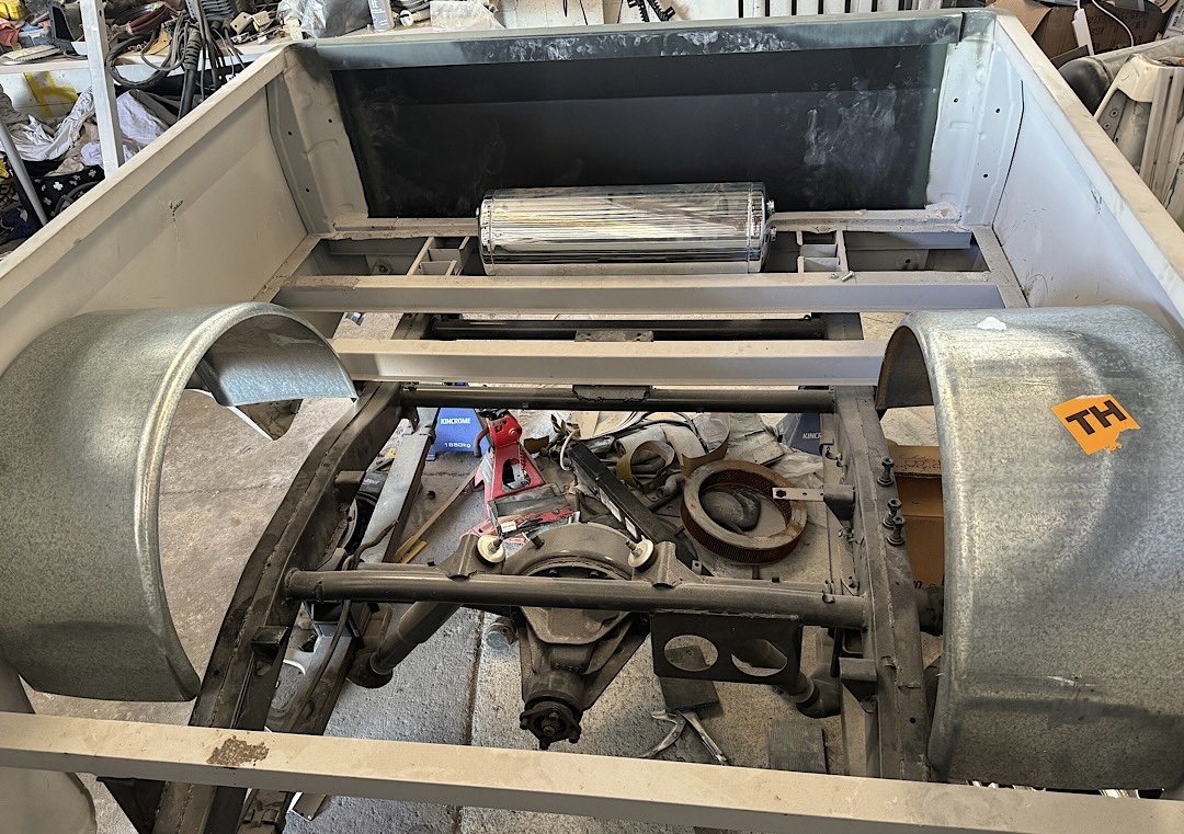
Picked up a pair of trailer guards, aka wheel tubs from a solid GC today. just sat them in place where I think they’ll end up, or there abouts. stood back and admired the look, quite like it. still need to trim to fit snug once it’s all decided.
2 points
-
Just needs a couple of LED whippy boys on both sides of the front bumper and a kenworth windscreen banner2 points
-
2 points
-
Replaced oil pump with other unit I have with the SQ Engineering additional relief valve spring setup to bump up the pressure, we seem to be good! If that still doesn't give me good pressure at all times i'll flick the cam caps off and have a measure up New Speedo drive is in so I've now got a work speedo Think that's it really, time for cert? Bumper is back and looking absolutely insane if you compare to what it was previously!2 points
-
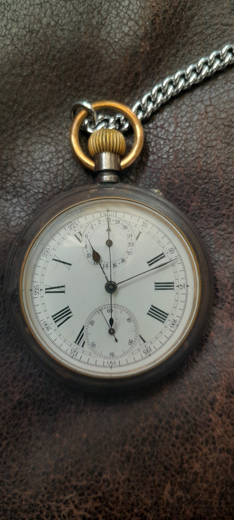
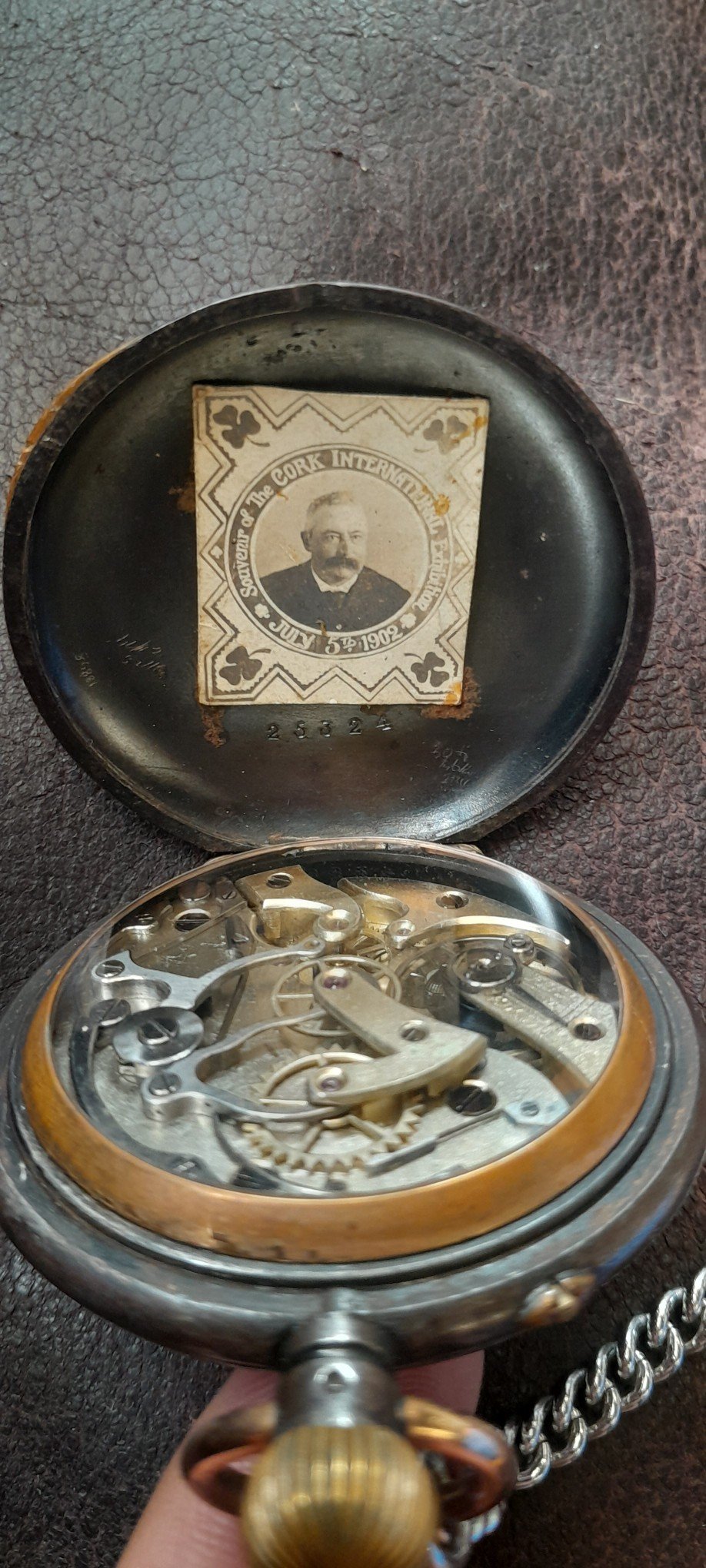
My parents gave me this for my 21st It came with a card that says W.W.I MAJOR JENNINGS D.S.O. Google wasn't around when I got the watch, but now it is, so o know he was a surgeon. http://www.maltaramc.com/ramcoff/j/jenningsjw.html
2 points
-
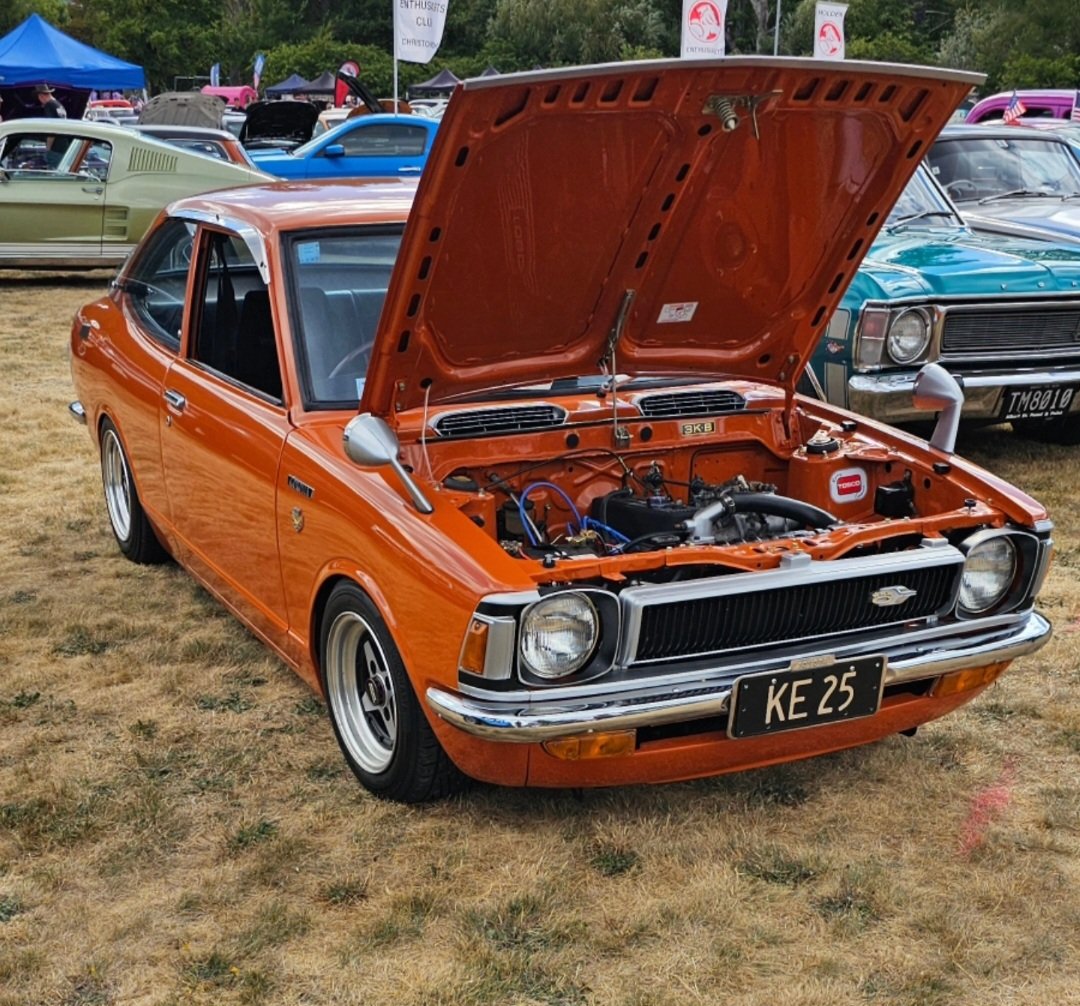
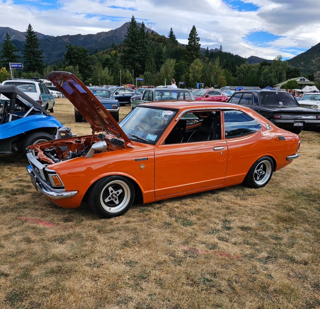
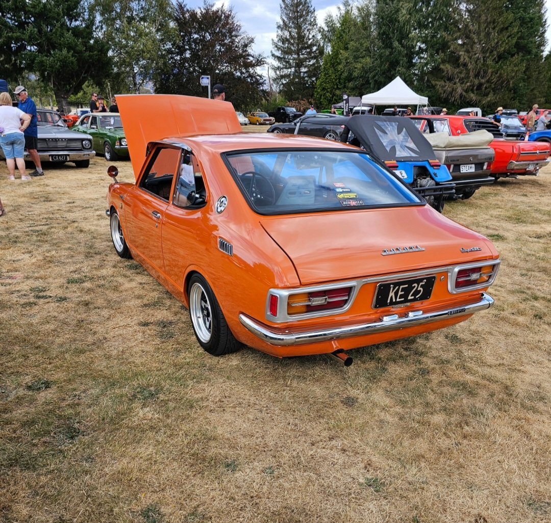
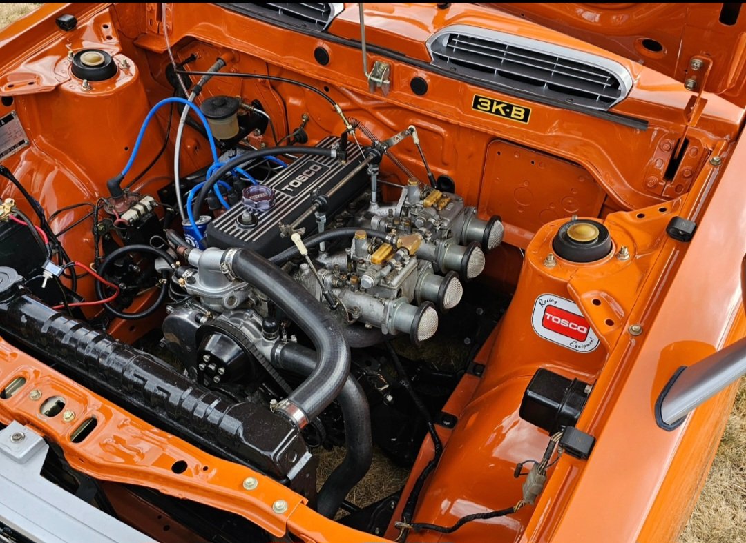
Hanmer car show
2 points
-
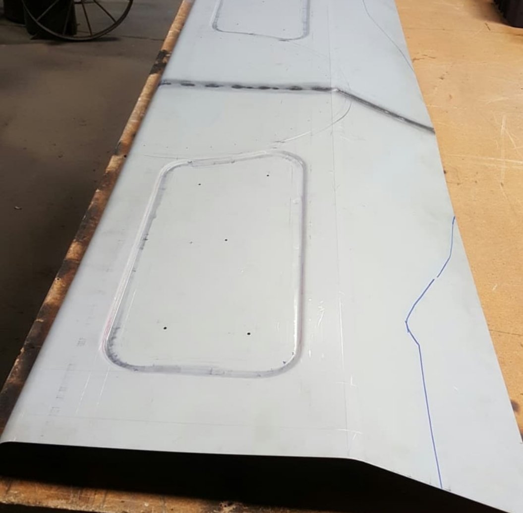
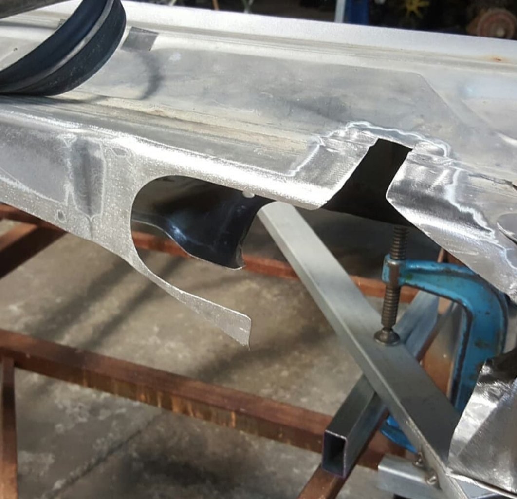
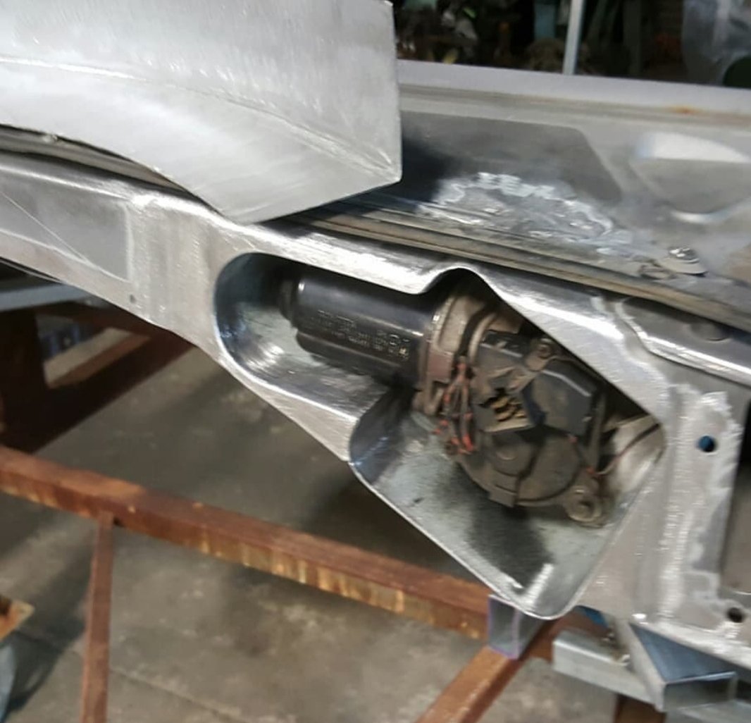
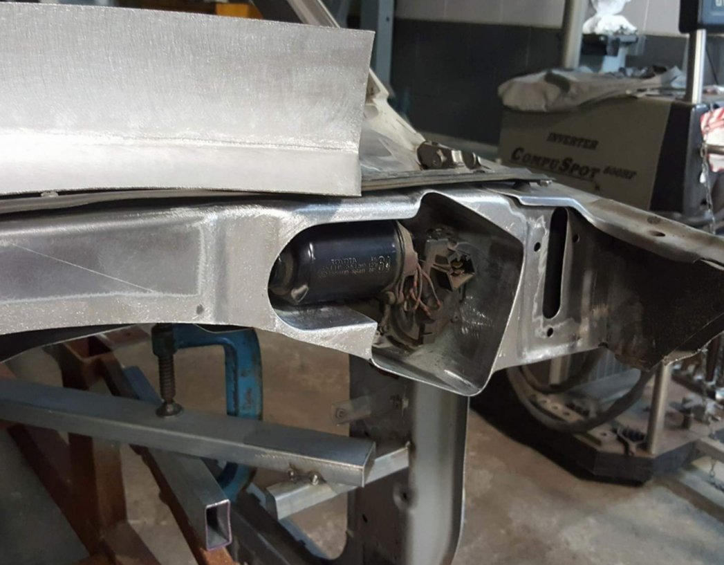
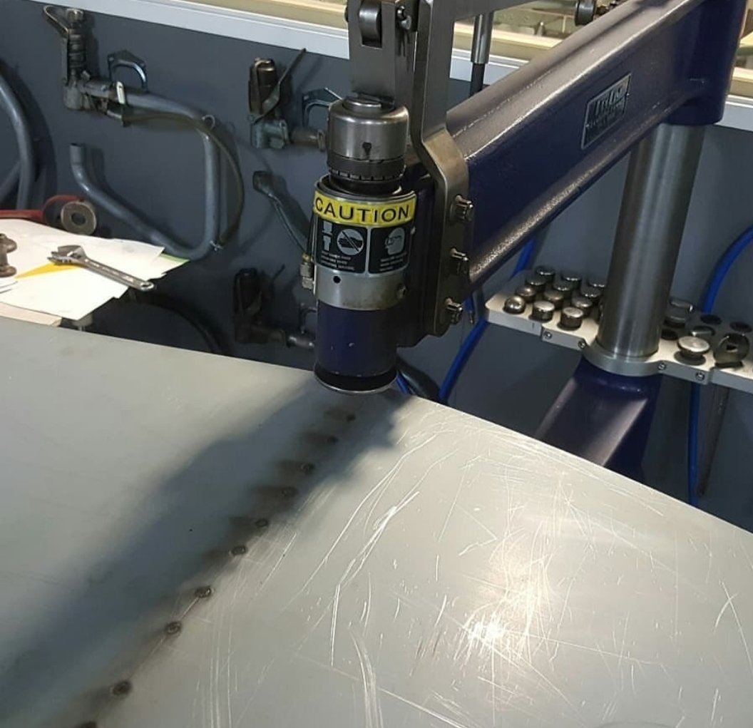
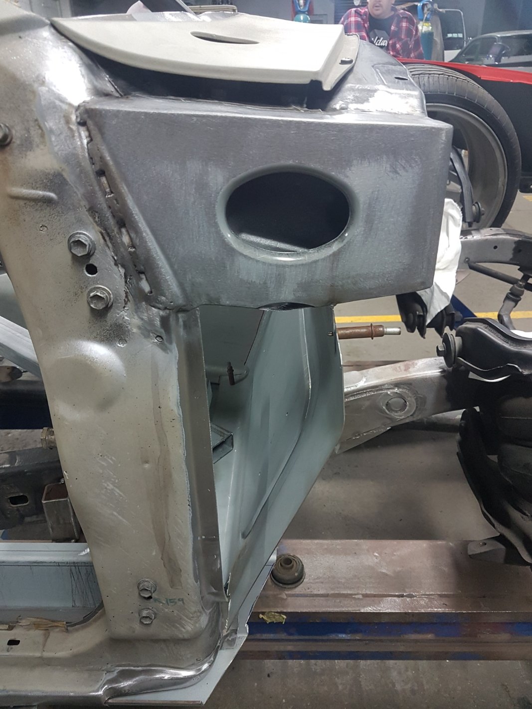
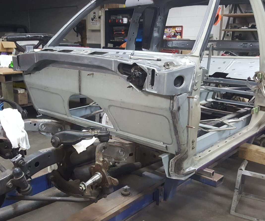
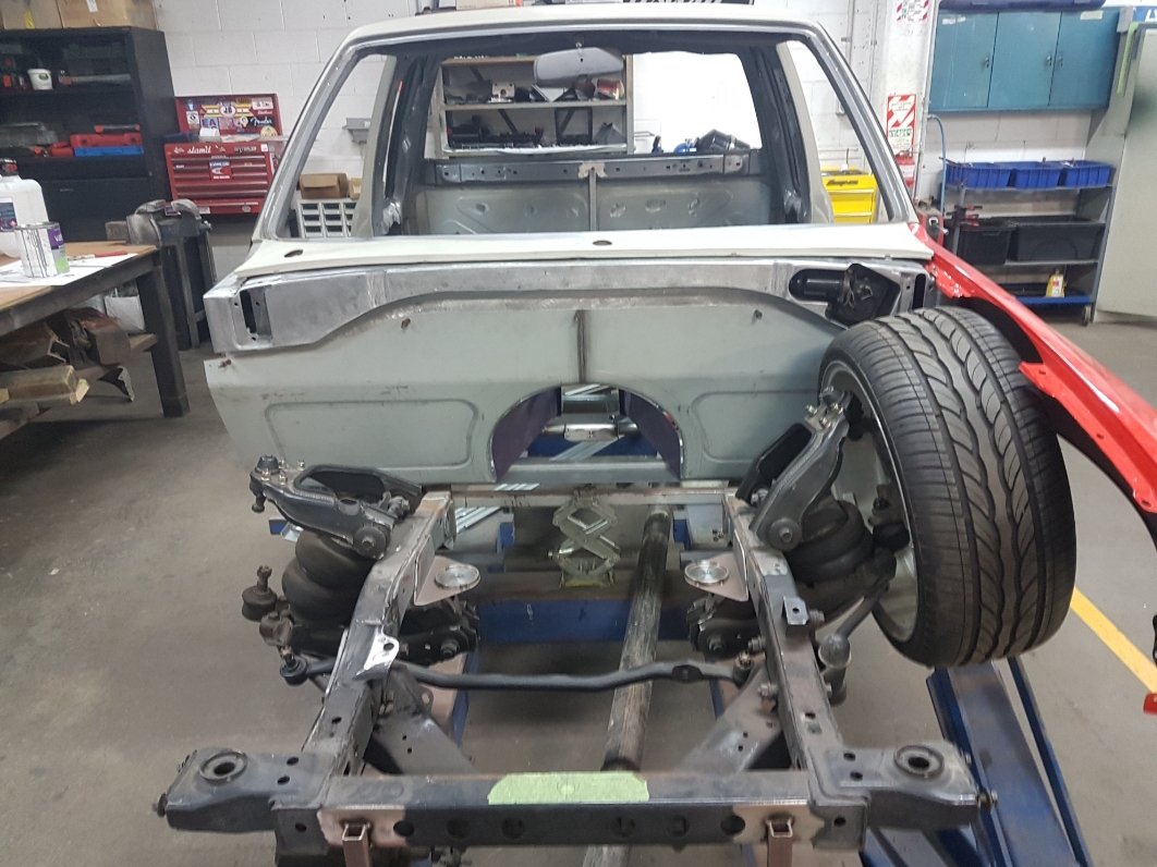
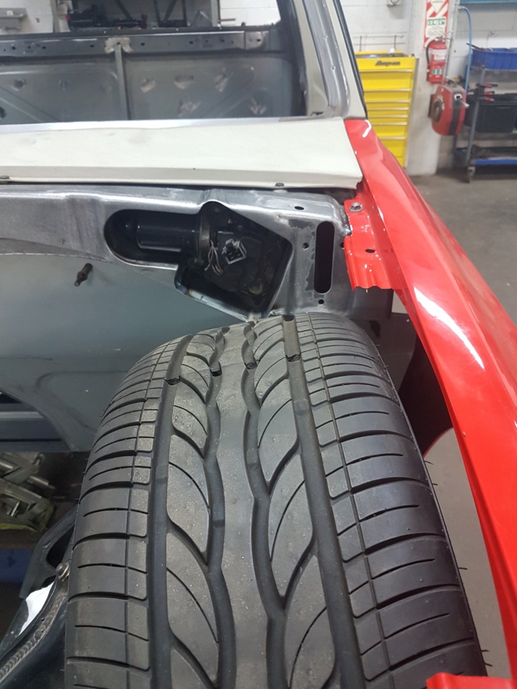
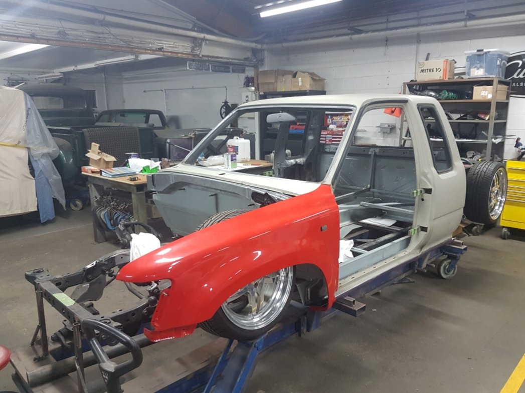
Here's the process of forming the front firewall..... All the correct tooling has been used, such as the planishing hammer, to spot welding it in. You could call it a c10 style firewall, it's all going to be exposed with no wheel tubs. Check out the 'frenched' in wiper motor, I've never seen this done before and I was blown away when Matt surprised me with this! Wayyy cool. Also with the body drop, the steering has to be reconfigured, this is now ticked off the list
2 points
-
I think I might know what the starting problem is... Pretty sure that should be something over 12VDC. Charged it for another 24hrs with it disconnected from the car and still 9.8V. This has dropped at least one cell, probably shorted since it had none volts before I charged it. I haven't checked the alternator voltage but I'll get a new battery and check it then. The car could still have a short draining the battery but easy enough to check if there is current draw when I fit the new one.
1 point
-
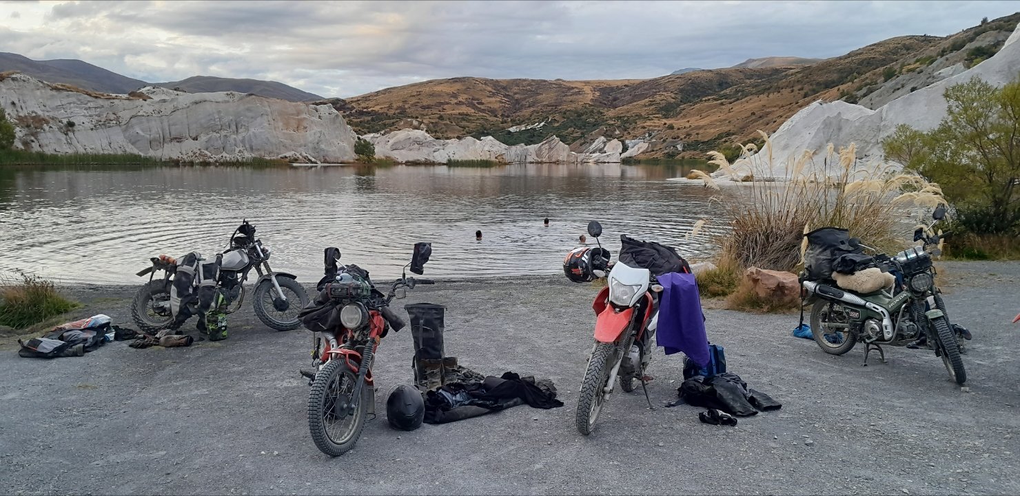
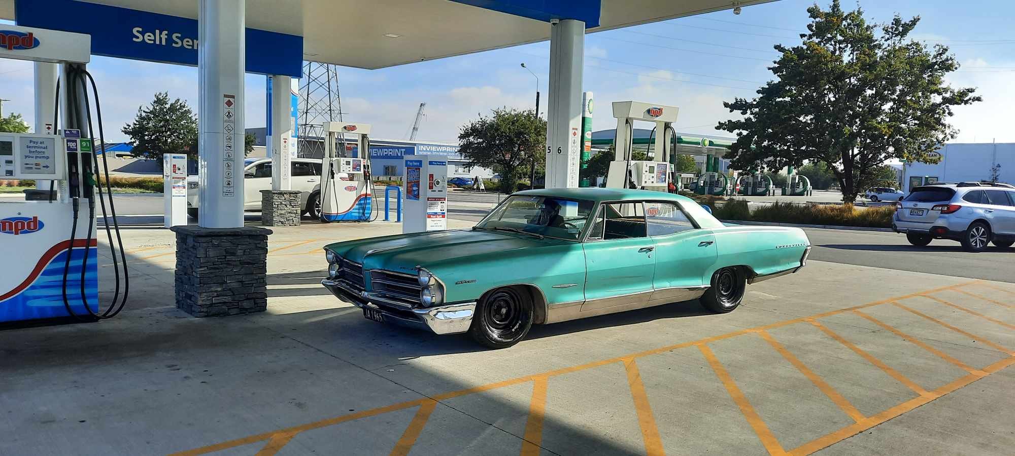
Went to hanmer motorfest for the day. Only took a pic when I filled it with gas
1 point
-
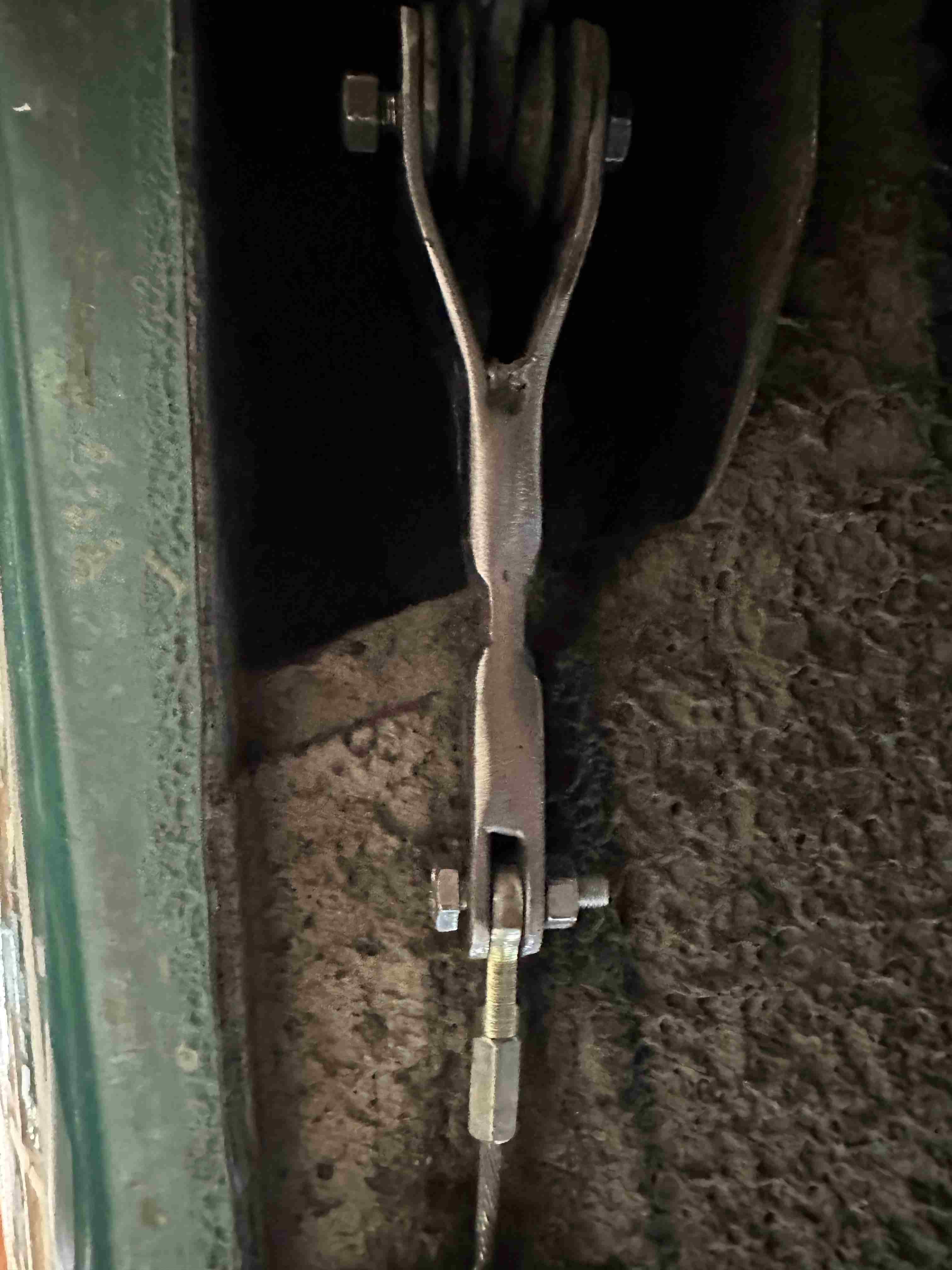
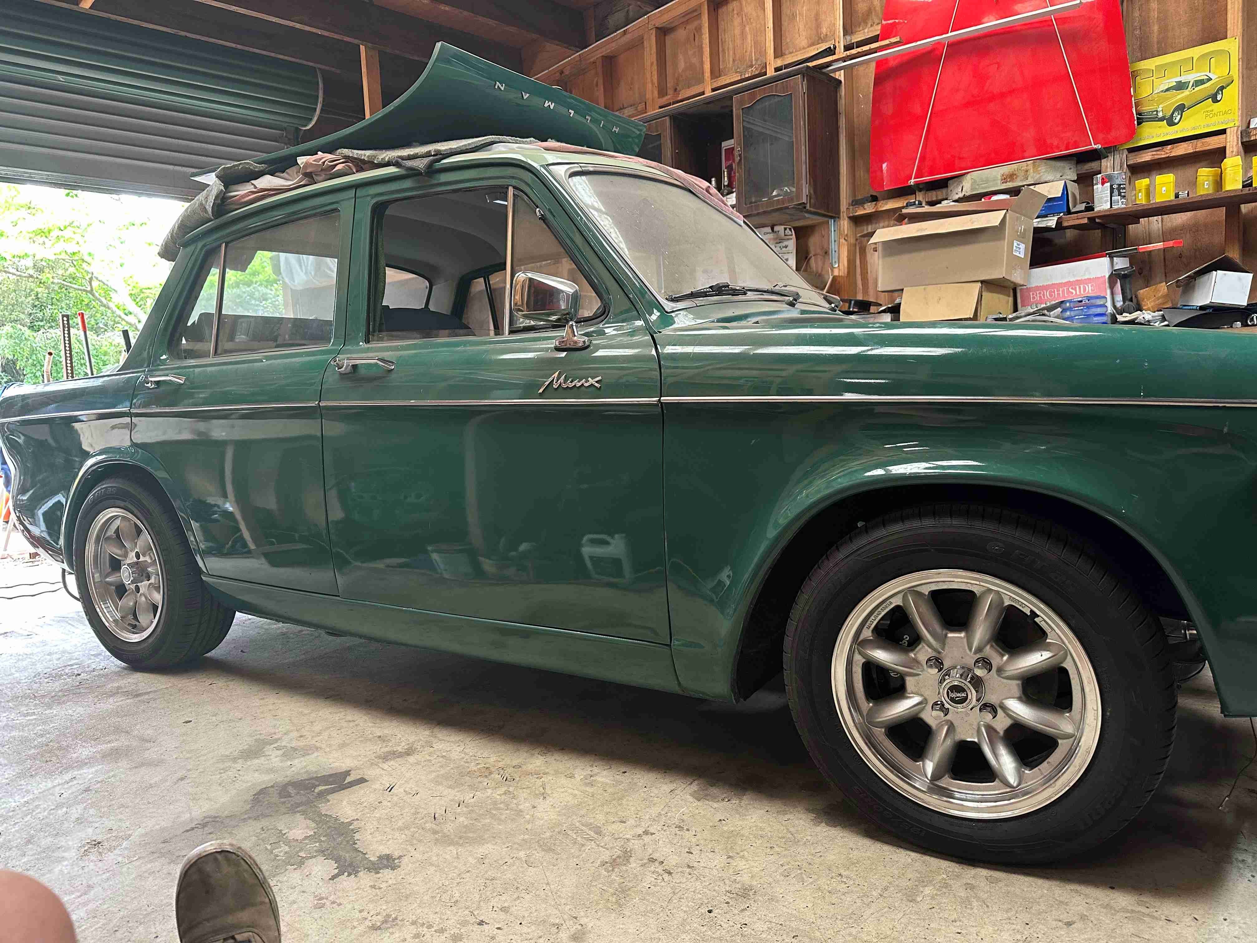
Today I mounted the hand brake cable back onto the Avenger diff and brought it around to the Minx hand brake lever. I needed to make up a bracket to connect it but all else fitted up well. So that worked out well and now I have a working handbrake. I also put the rear springs in and bolted the front X member back in with the springs but without any shocks yet. I wanted to see how it sat with the stock Avenger rear springs and 50mm cut from the Minx front springs. I threw in the seats a full fuel container a battery the intake, alternator etc to try and get it as close as I could to the weight it will be. Still needs fluids, bumpers and a few other smaller items. So this is how it sits at the moment which is quite promising. I might drag it outside tomorrow and give it a bath and have a decent look. If I want it lower it would not be by much. Once I have decided I will get new front springs made and rear if I want it lower. Back on it's wheels for the first time must call for a small celebratory refreshment I would think. Sort of like a roof shout.
1 point
-
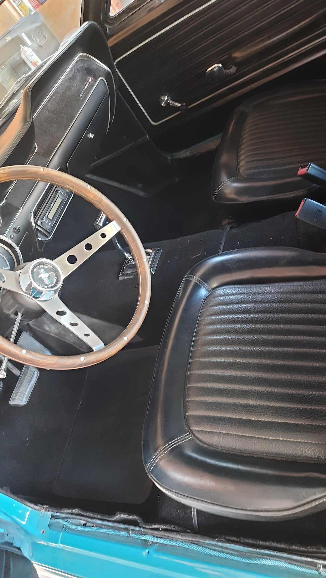
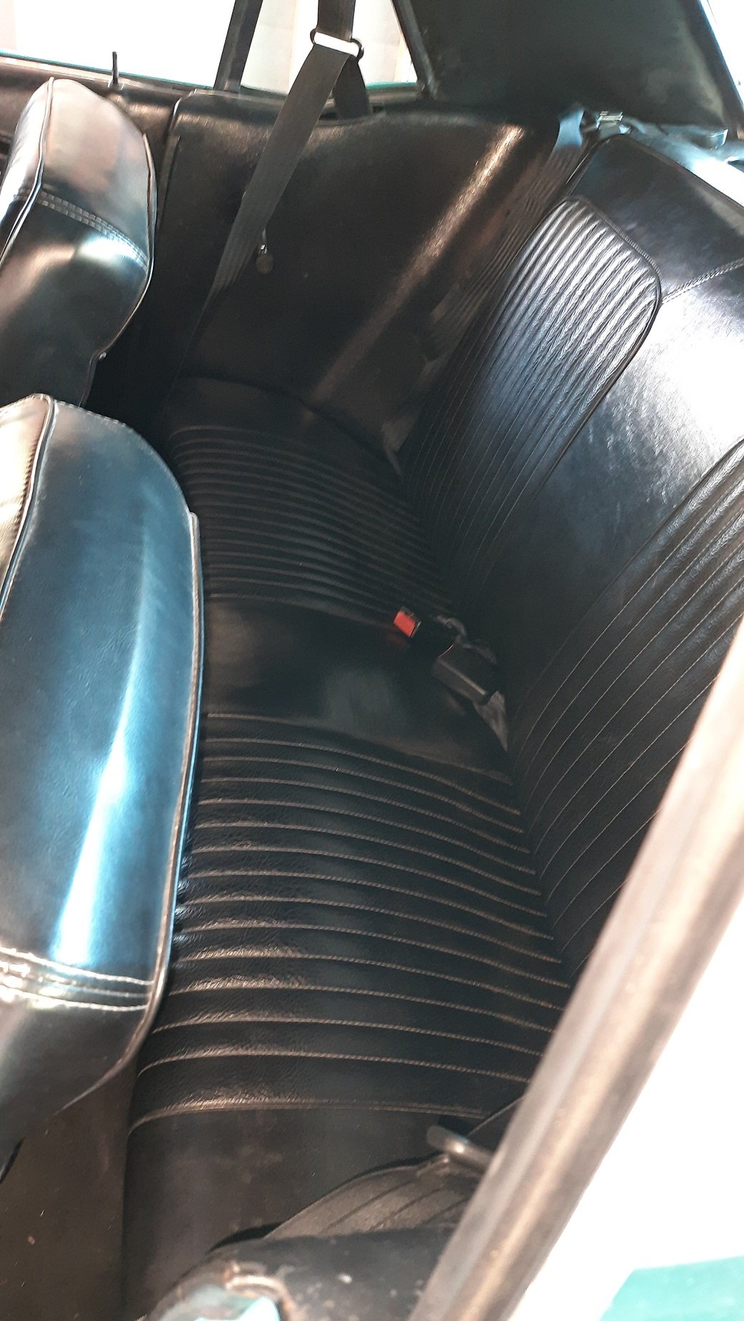
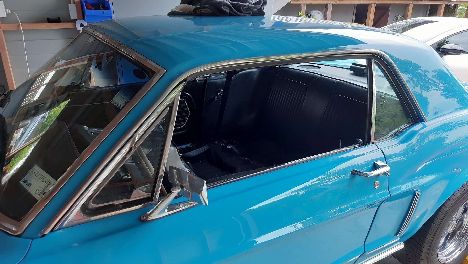
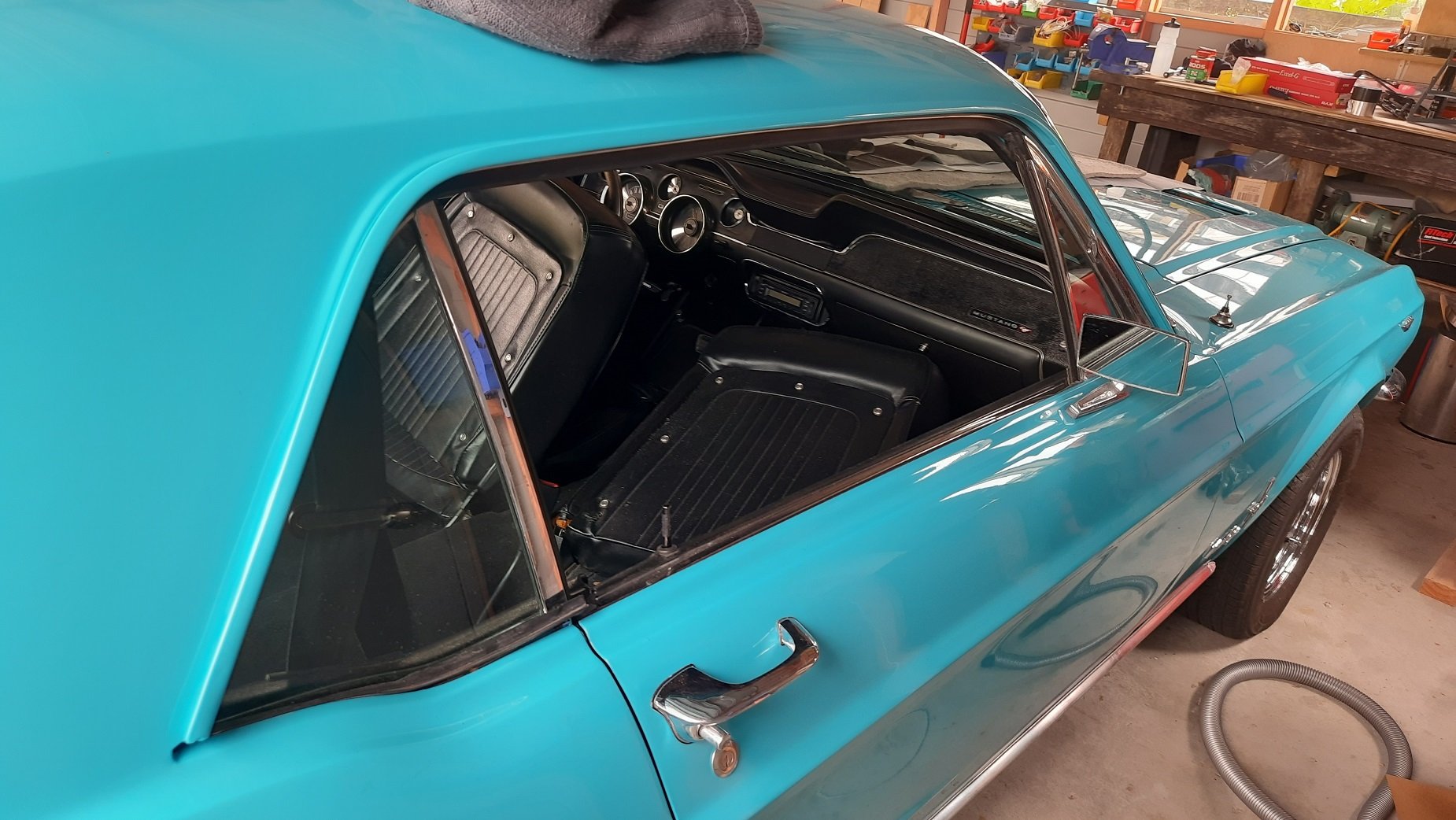
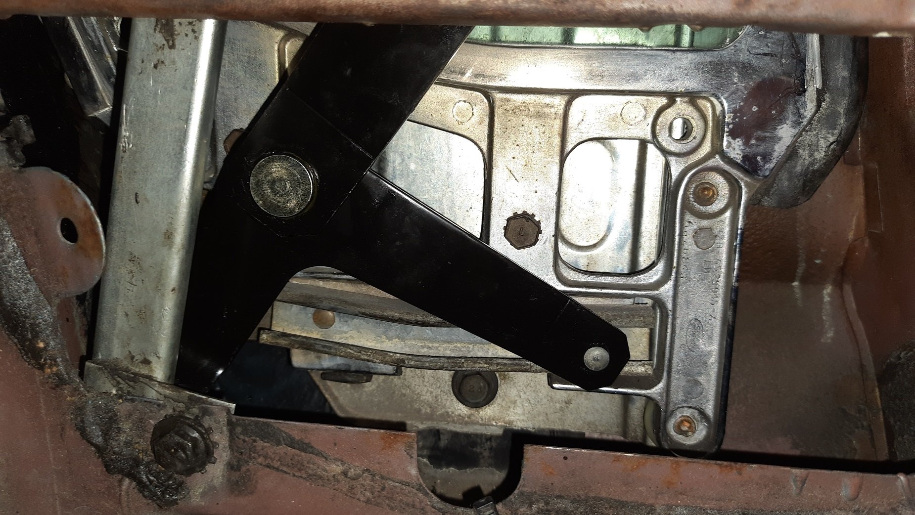
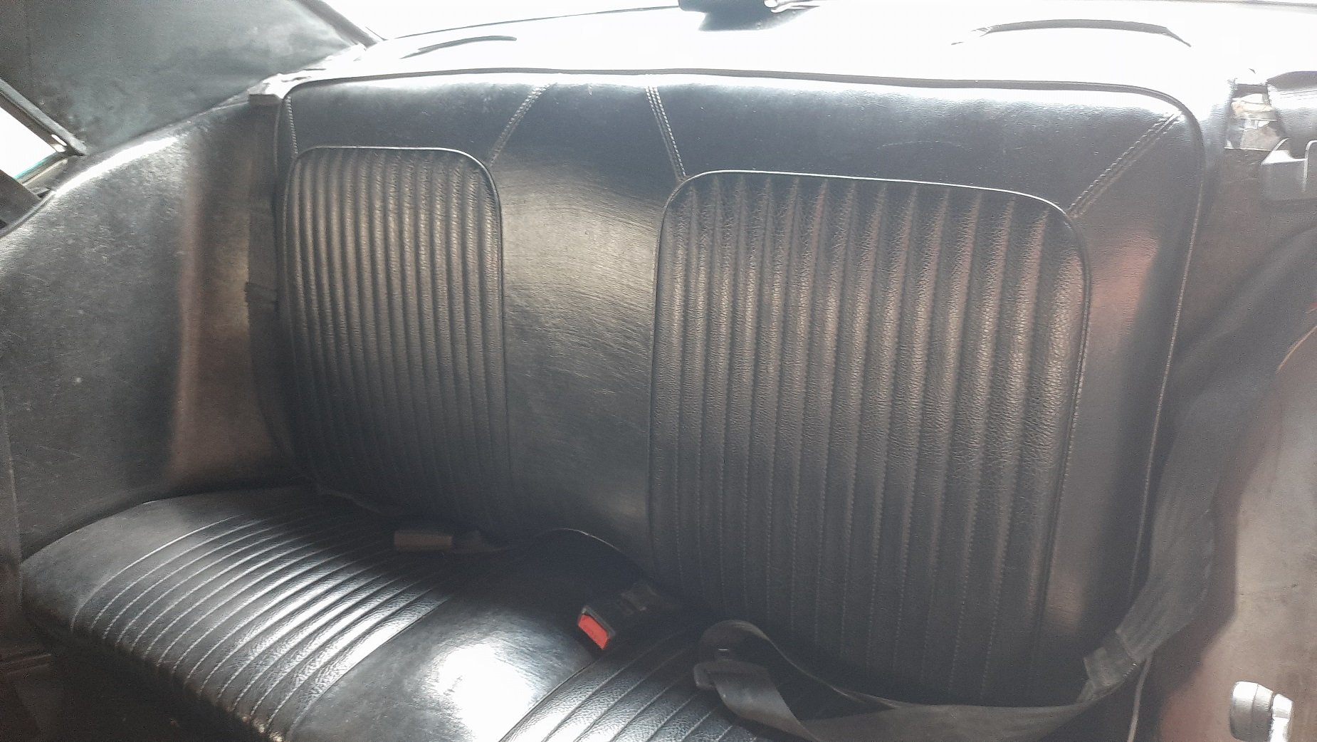
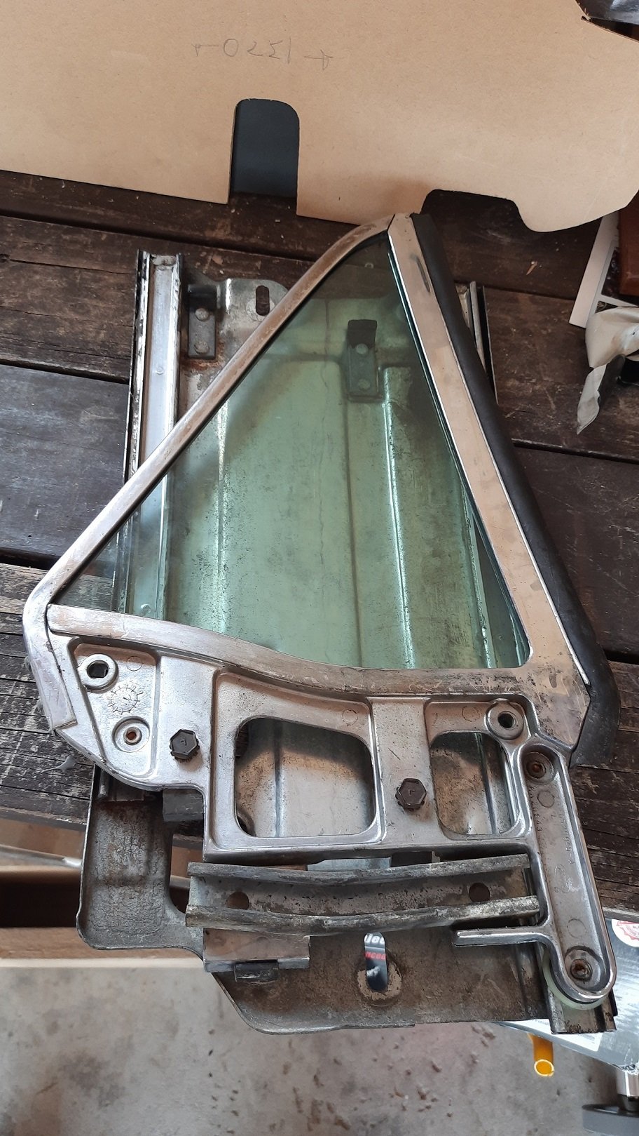
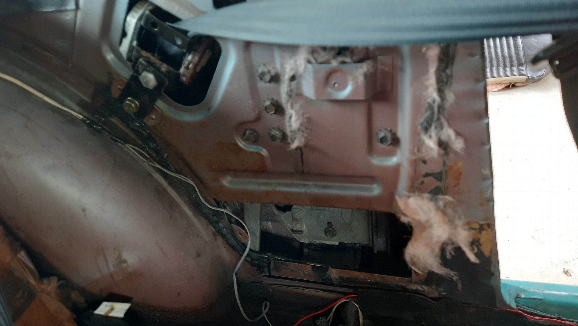
Post sound insulation I reinstalled the underlay and carpet. Looks like new... or just like it did before I mucked with it. Seats and trim panels back in. I also got a guy in to replace the drivers seatbelt so once the driveshaft is back in it is good to go. Then I tried the rear windows again as they are a bit tight. The passenger side went up then slightly down before binding and going bang. The new regulator is now bent along with the vertical guide. Obviously it was not properly aligned and bound up. Fuckit. I'll deal with that later. Running out of cash to spend and fucks to give on windows for a while. I'll get it running, warranted, maybe do the shocks and bushes and then bother with windows again.
1 point
-
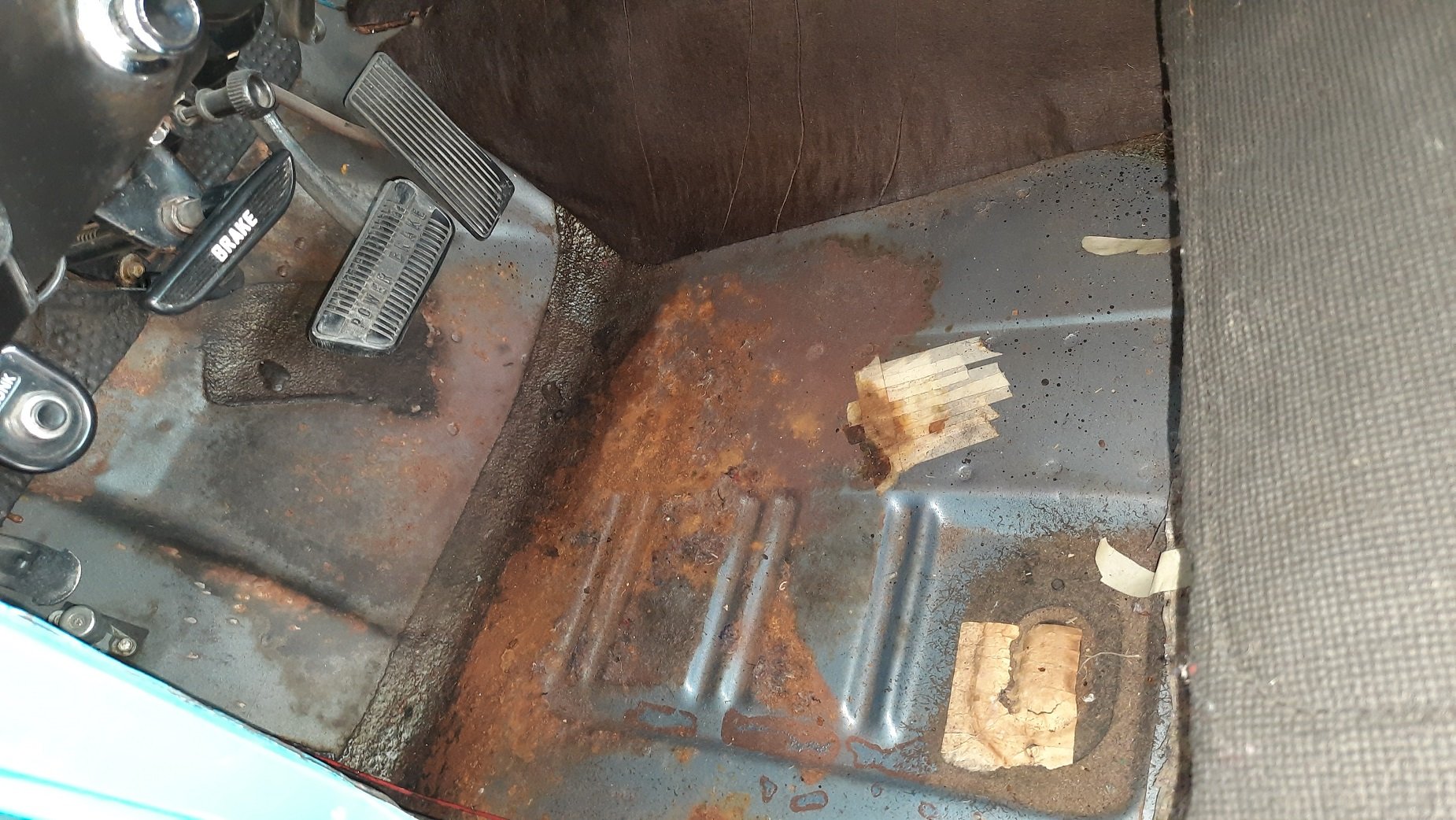
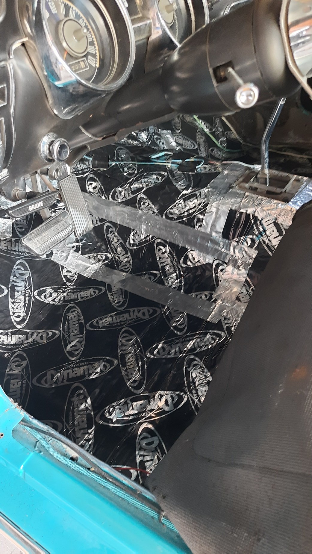
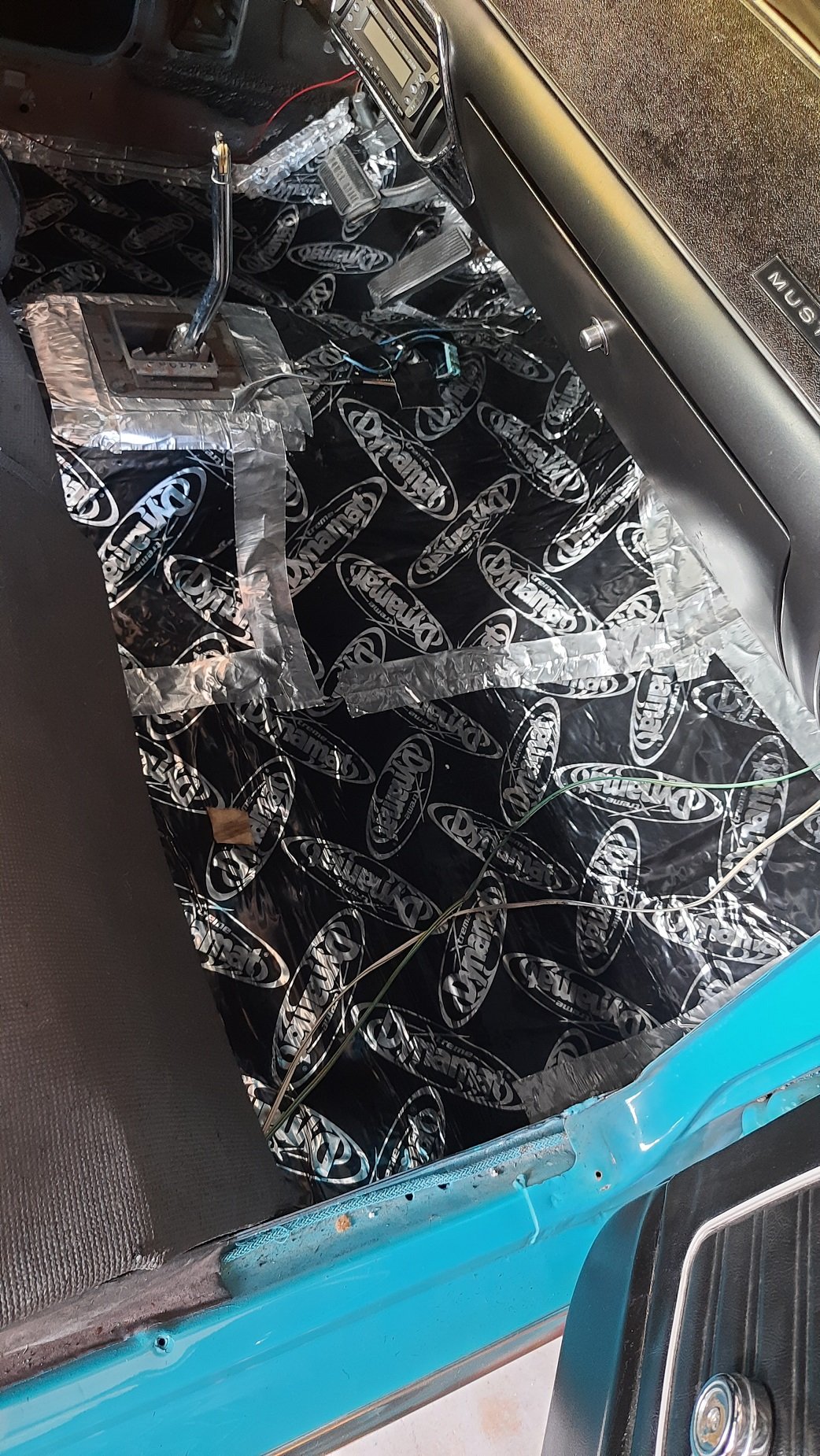
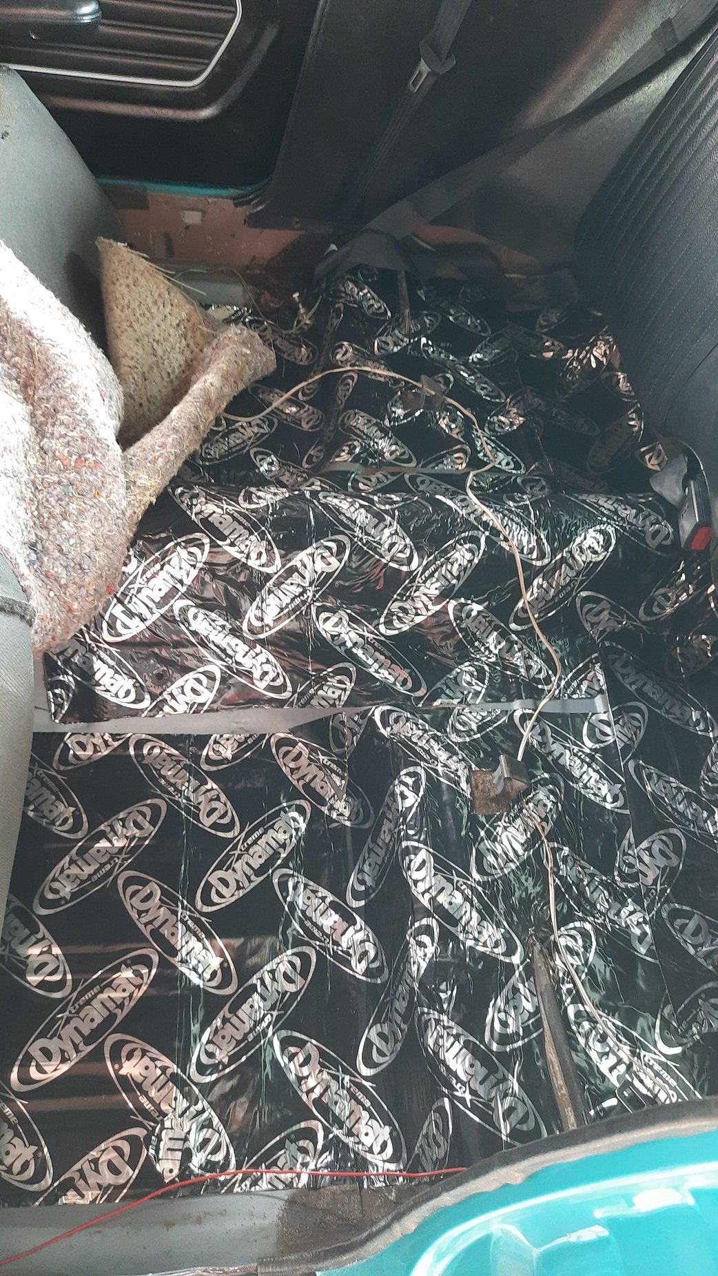
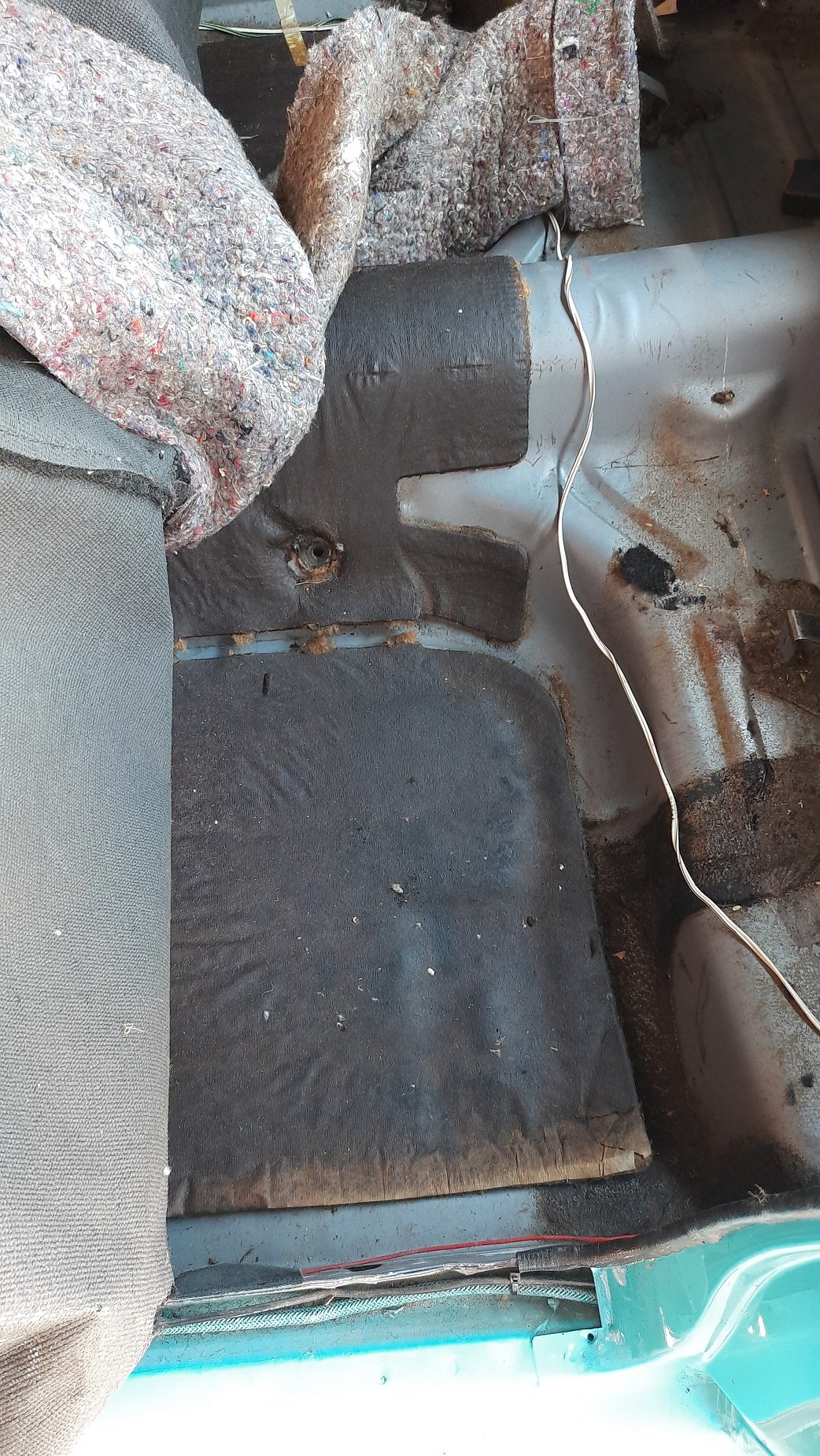
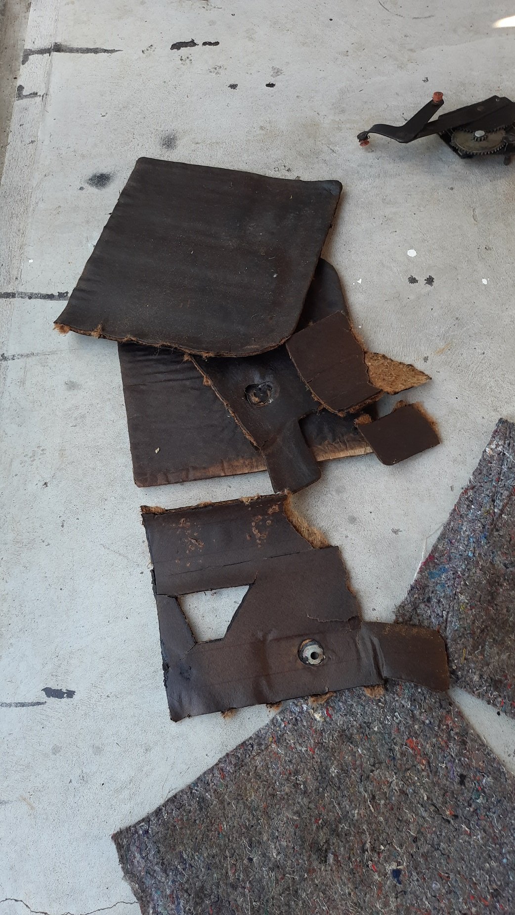
Finished the sound deadening. There was a bit of red stuff under the drivers feet, and no original sound insulation. I'm picking there was a bit of a leak so they removed the insulation but didn't treat anything. I gave this a wire brush and sprayed some rust converter. I didn't have any POR or Brunox so I just sprayed some primer and flat black. Didn't take a photo. The passenger side still had the original sound insulation Ripped it out again and this side was much cleaner than the drivers side A couple of mats and tape and it is now all covered except under the front seats.
1 point
-
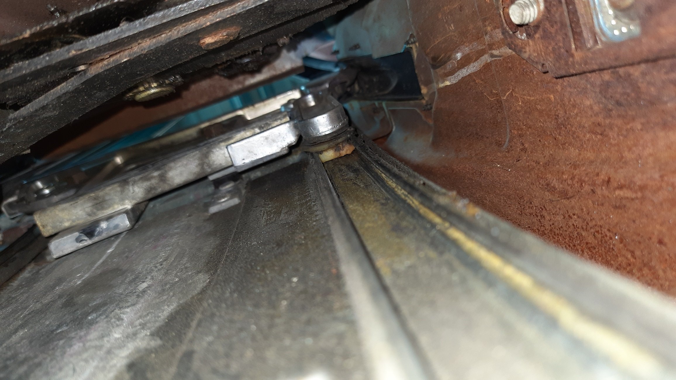
Finished up on the sound deadening in the rear. Just worked with the carpet pulled back. Dynamat is much easier to use than I thought. Got it all laid nicely and then put the underlay back on top. I then had a go at refitting the chrome trim around the drip rail. I used a bit of Dow Corning 4 silicon grease on the rail and it slipped on reasonably easily. The right hand side did not play the game nicely though. I could get it on in places but not all the way and didn't want to smash it on. I think the thickness of the paint makes a bit of a difference I may try again later or just get my panel guy to give me a hand for 5 min. (or 30s probably) Side with no chrome: I also jacked up the car and measured the driveshaft. It is about 35-40mm between the spider and the diff yoke once disconnected and pushed fully forward (at ride height) which I think is about right. I just need to check if the driveshaft guy can make a new one minus the extra welds and dodgyness. With it up in the air it is less than 5min to get it out so easy job.
1 point
-
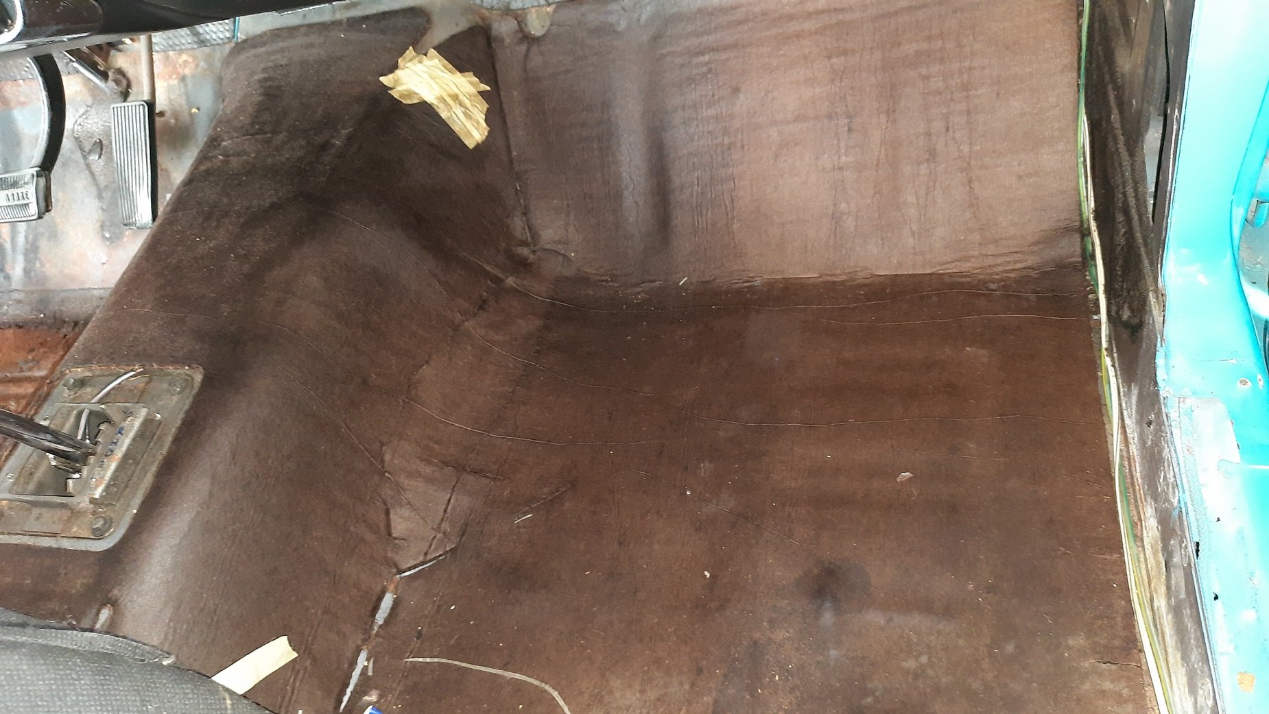
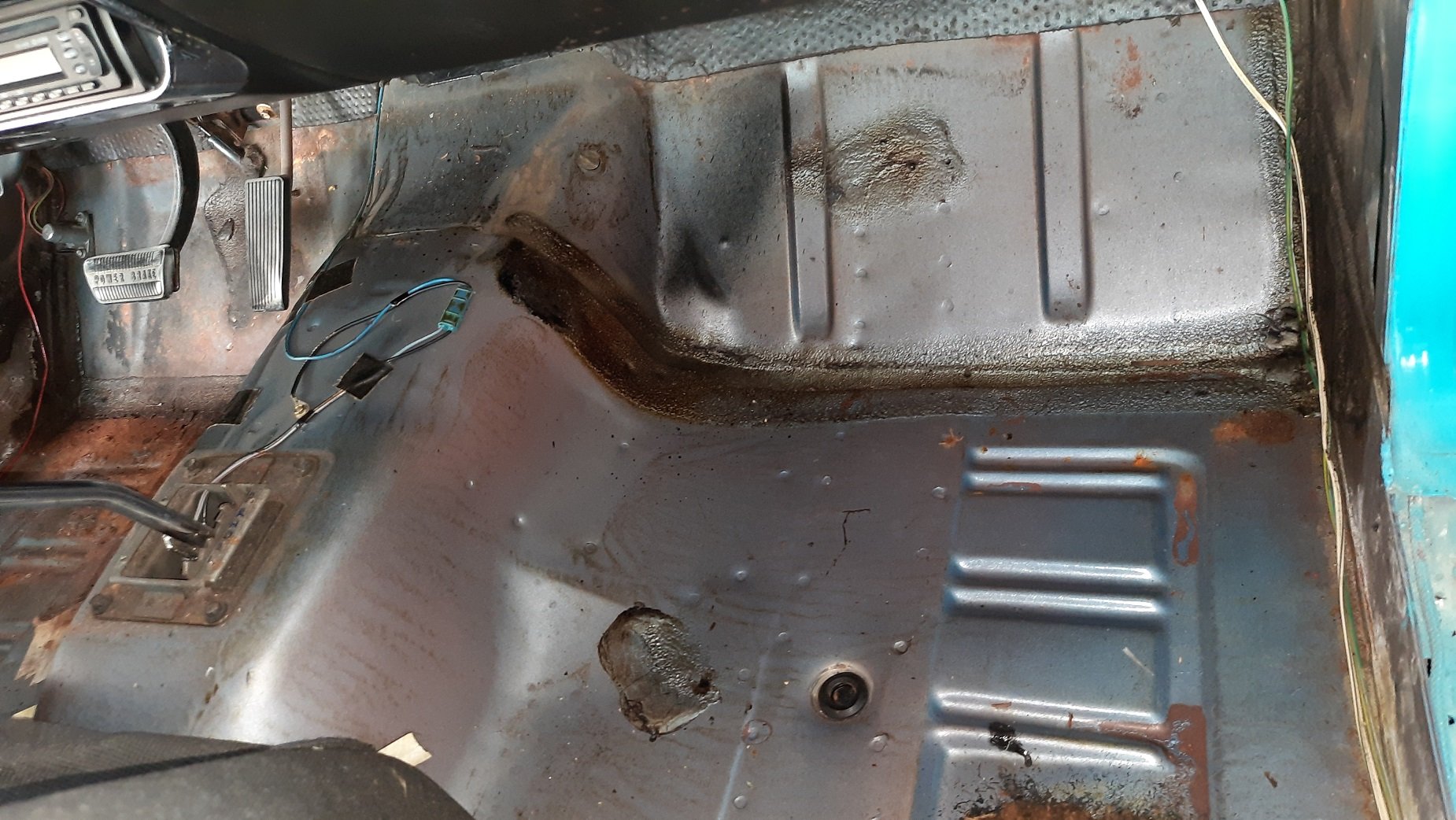
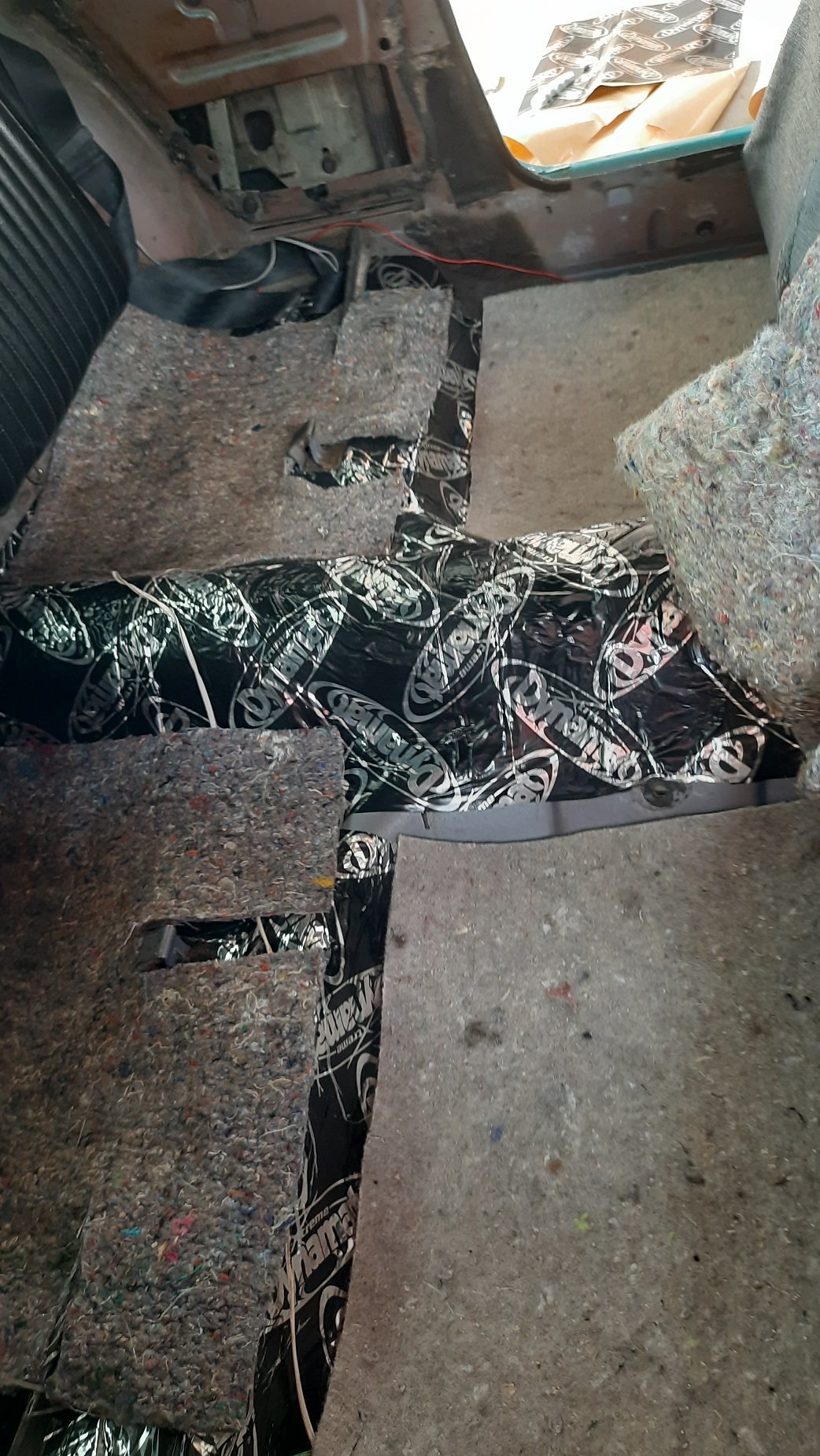
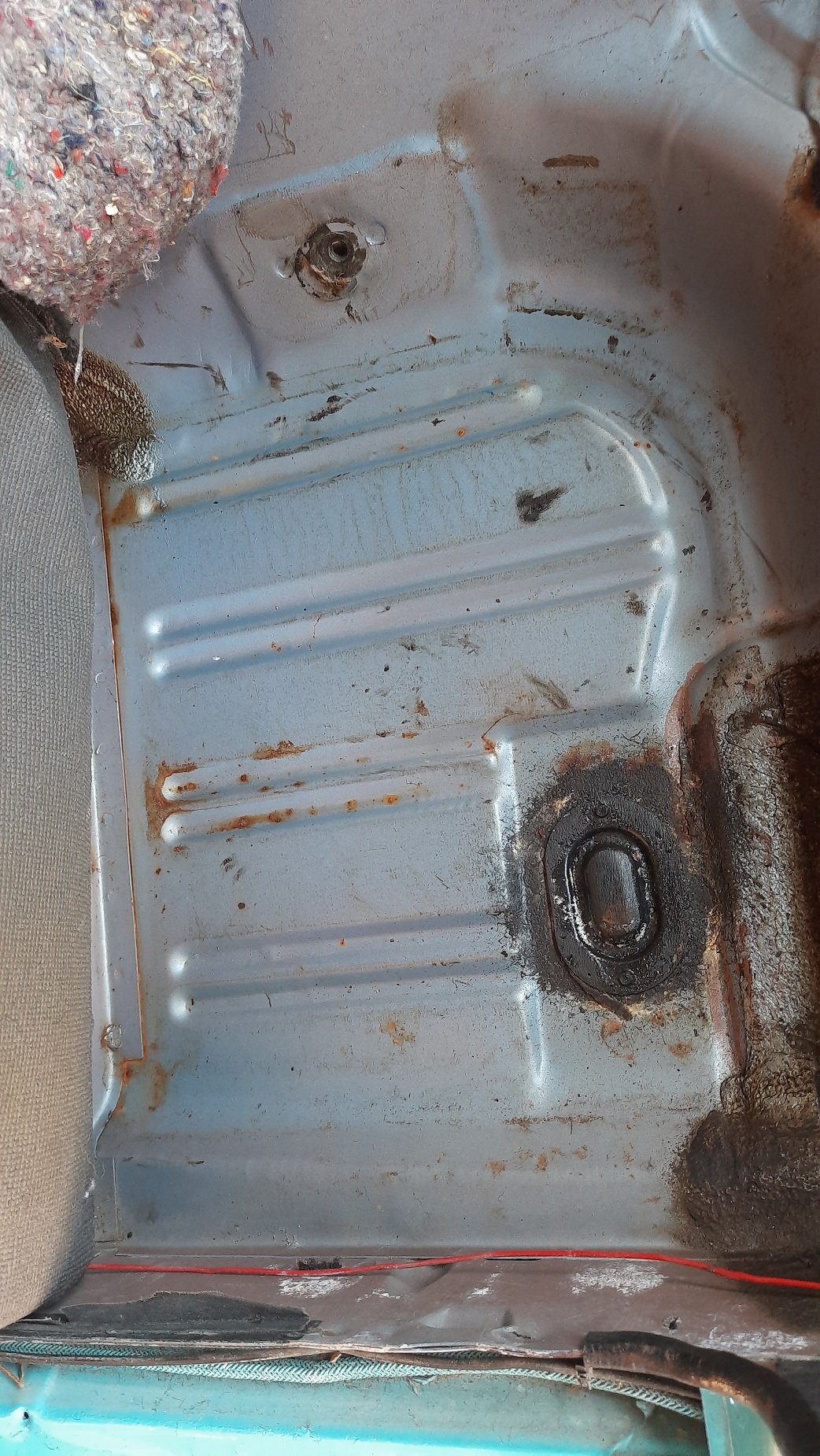
Next step is the underlay and sound deadening. I took out the rear underlay and it has what looks like the factory sound deadening. Sort of a rubbery mat with hessian type insulation. The underlay felt a bit damp from being there a while so is airing. I ripped out the sound deadener as I have new dynamat to use and the old stuff is degraded. I also wanted to check on the condition of the floor so up it came. Peeled out really easy so it would have been doing something but not as effective as it should have been. The floors though are mint Bit of brown in the seams but for what is probably 55 year old paint and no real rust in the floor. Sweet. Ideally I need the seats out to fully remove the carpet but I may just work around them as there is actually a double floor in that area, I assume that is the seam you can see left of the above pic. The nuts are in the upper skin through a small hole in the main shell but with long bolts so I need a really long reach socket to get over the bolt and get the nut off. A standard short socket like mine will never get them off.
1 point
-
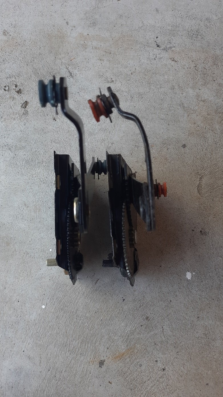
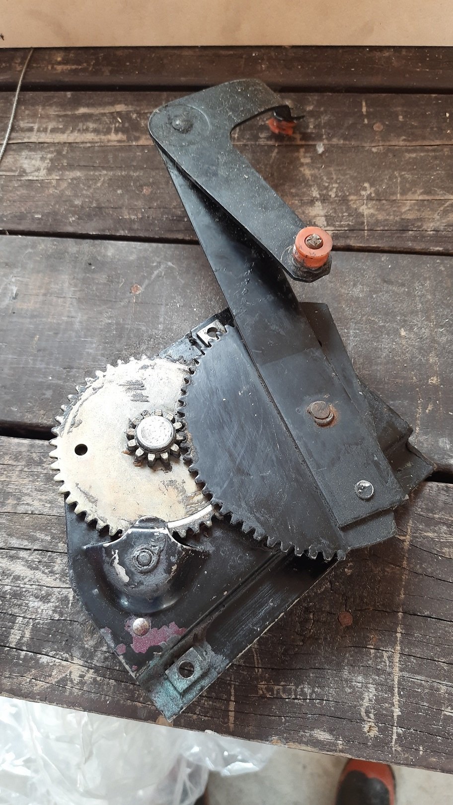
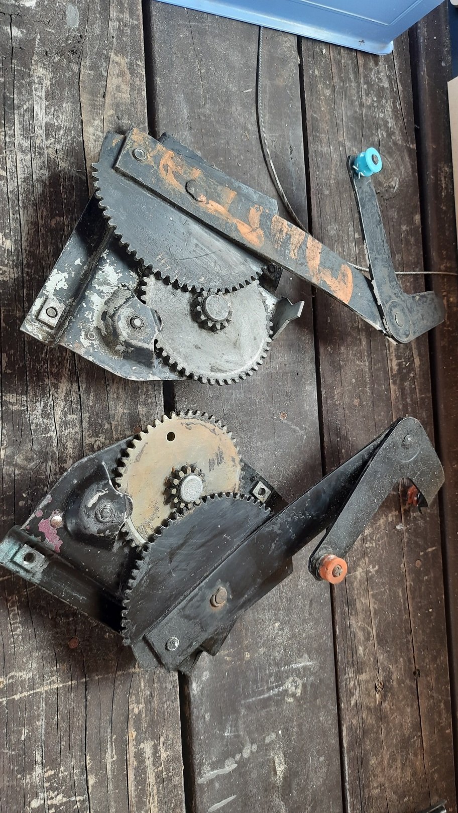
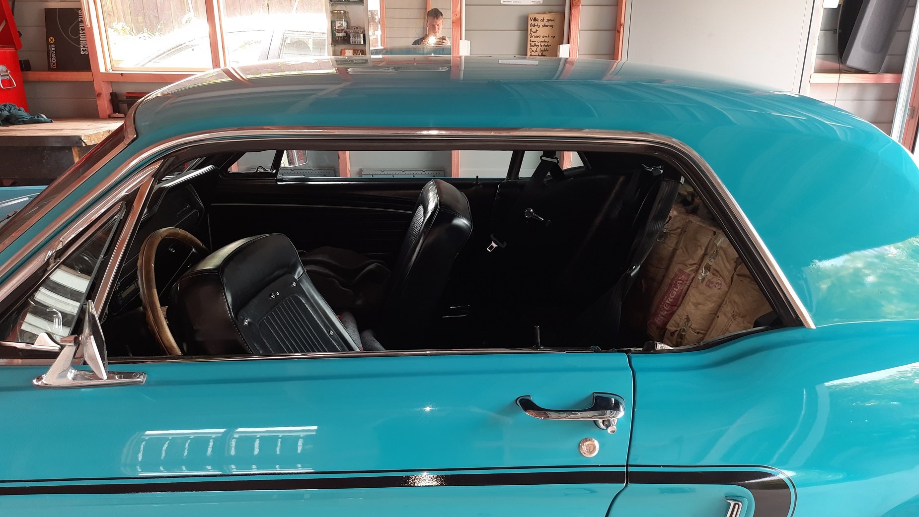
Got the new regulator for the rear windows and I initially thought the originals were not too bad until I sat them side by side. One of these things is not like the other one. The regulator on the other side was missing its rollers so easy to see why they didn't work. Fitted the new regulators and gave them a test. Windows go up, windows go down. Annoyingly but hand is that they don't interfere with the inertia reels at all. Tons of room. Handy as I can have windows and belts. Annoying as I pissed about for ages trying to gain more room for them and now have a locked LH (drivers side) inertia reel that is unusable when I could have left it alone, done nothing but fit new regulators and no problem bro. Fuckit.
1 point
-
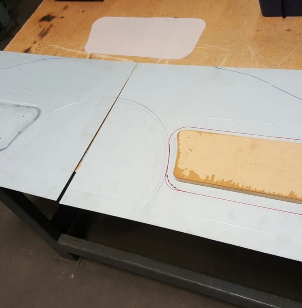
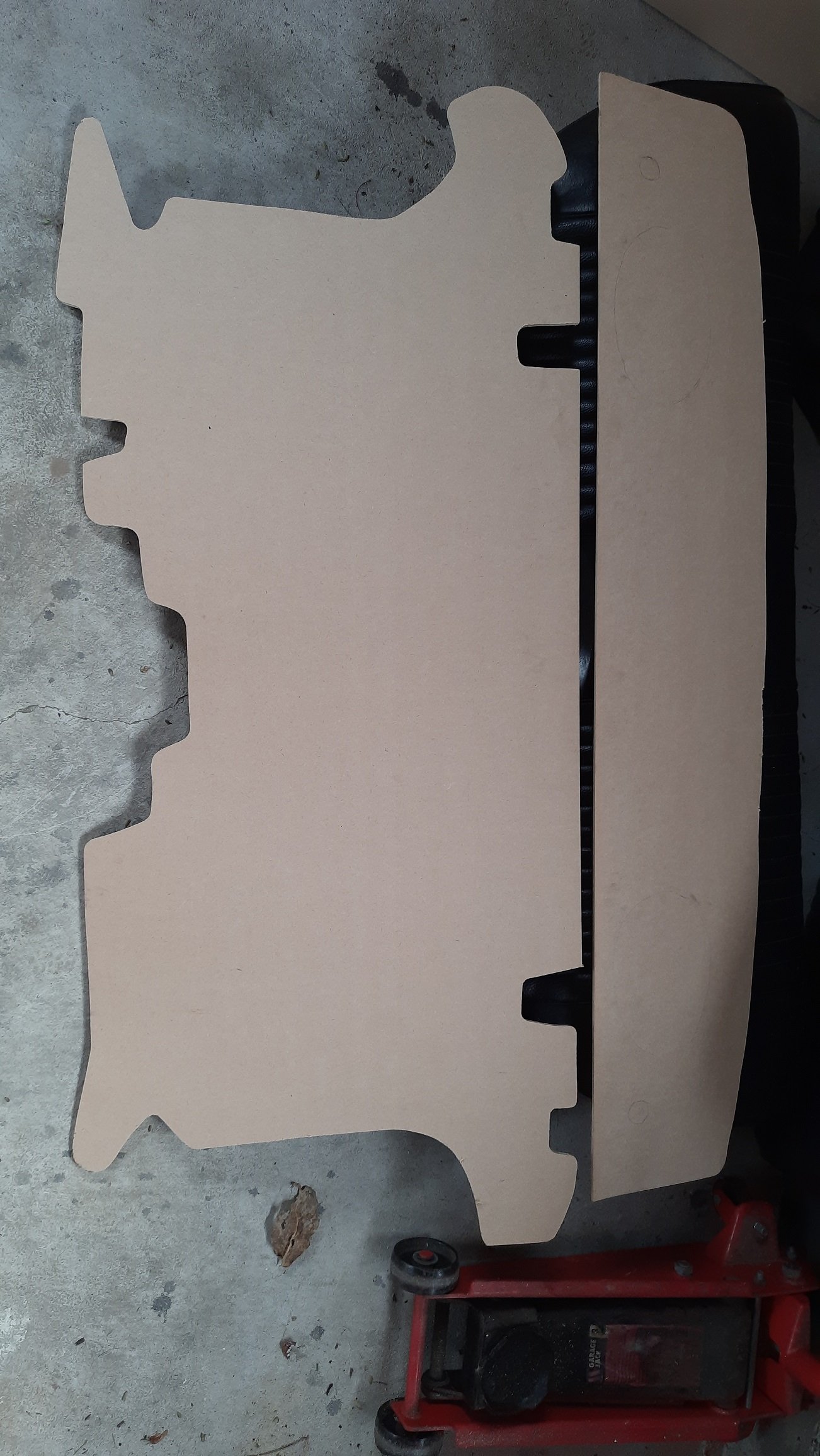
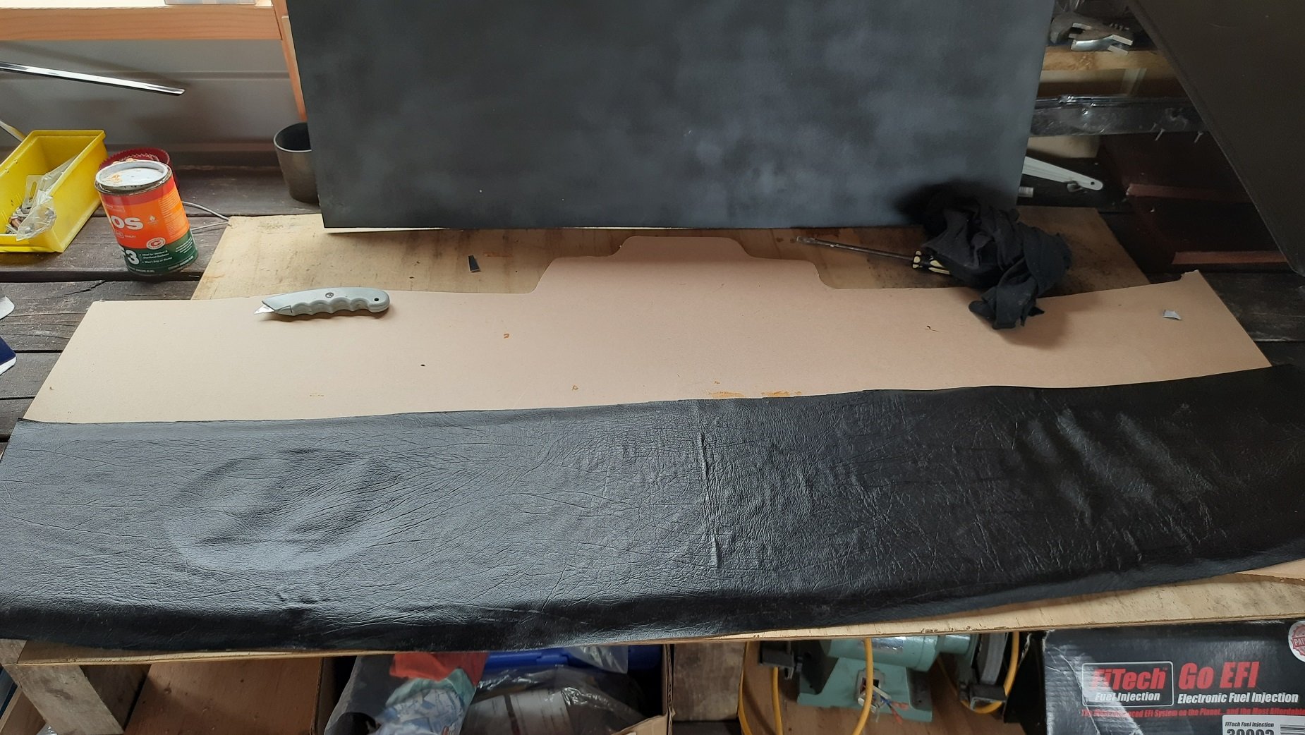
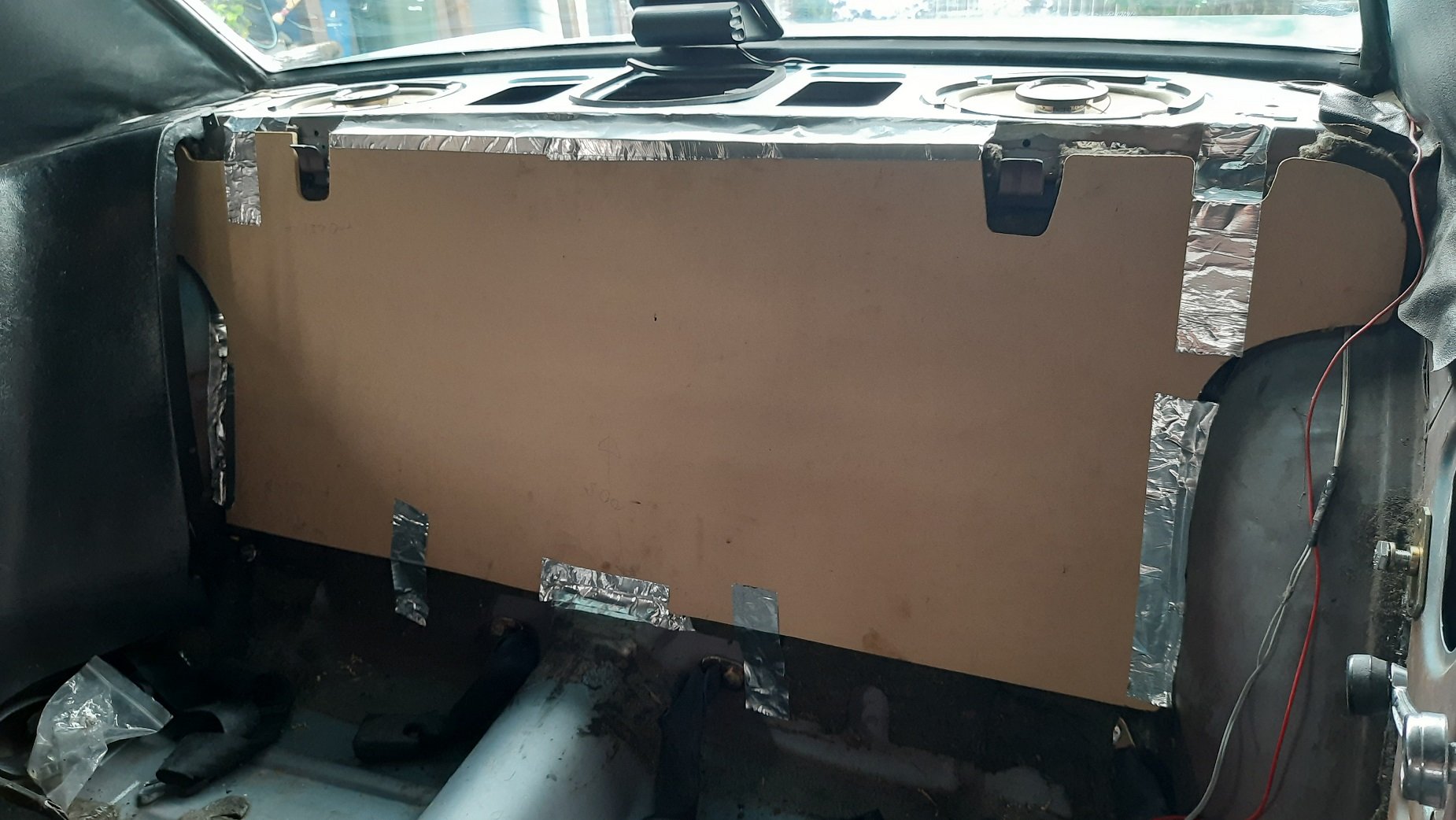
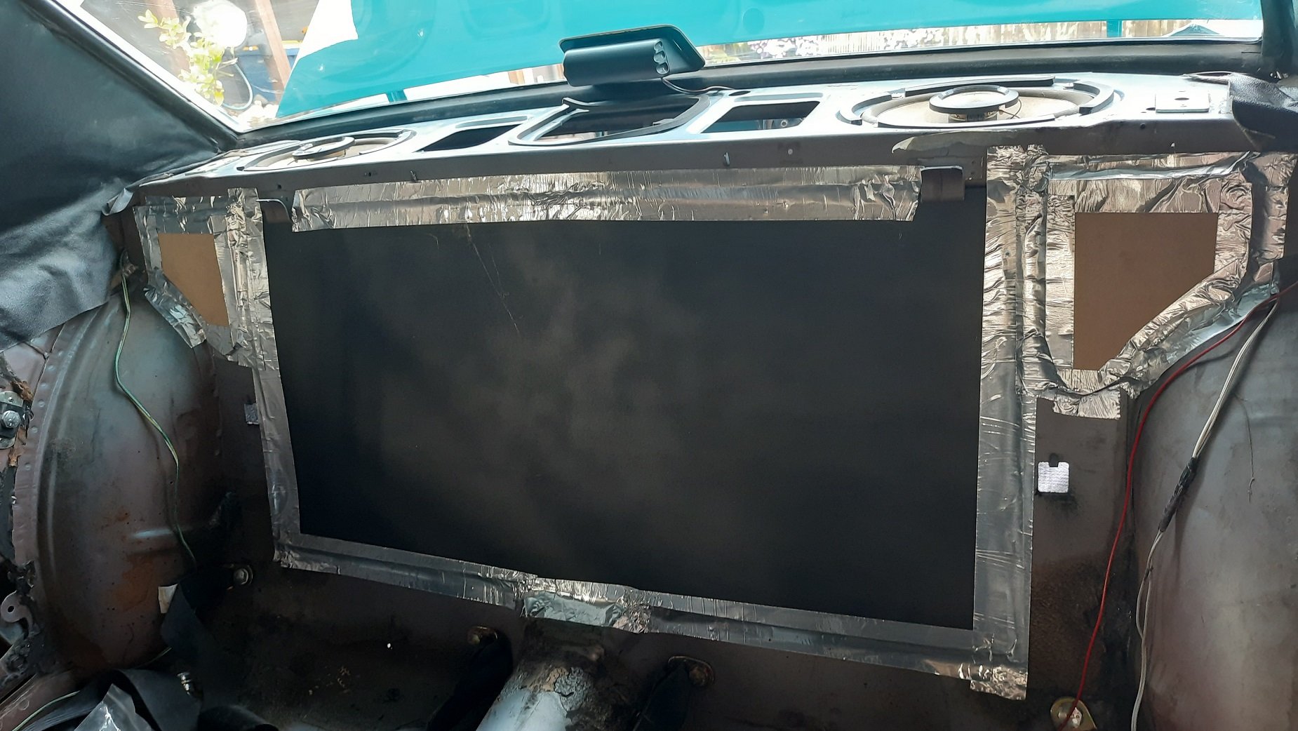
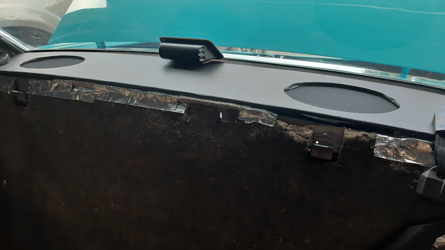
I ordered some new regulators and decided to work on the trunk divider and parcel tray while I waited. Cut some shape out of 9mm (I think) MDF. Some trial and error was required. Covered the parcel tray in vinyl, Ados F3 and staples to hold it. Not my best work but not terrible. The bracking and area behind the rear seat is not flat in so a flat piece of MDF would not work but slotted a rectangular part in with some glue, screws and ally tape. Cut the edges into smaller patches which are just taped in to place. Work on an aircraft skin at 400kts so should work here. Lots of tape. Another issue with the larger divider was it stuck out too far and the seat would not slot back in but this works. Finished the parcel tray with some holes for the speakers and speaker cloth. The corners look a bit average but I'll leave it till it annoys me too much and I'll just make another one. Looks good with the seat fitted.
1 point
-
Job done, hopefully I pick it up tomorrow and then can start the rest of my little jobs.
1 point
-
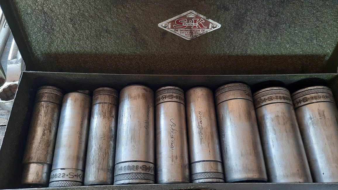
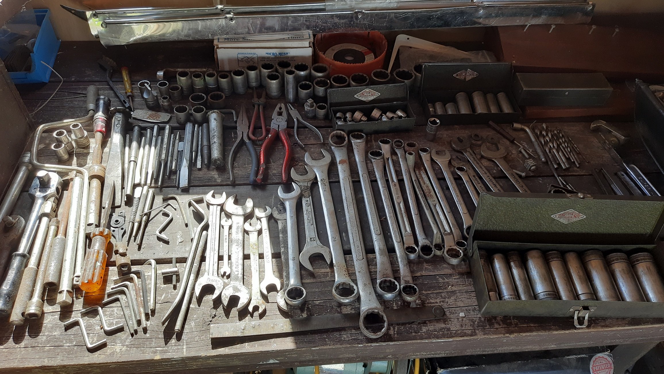
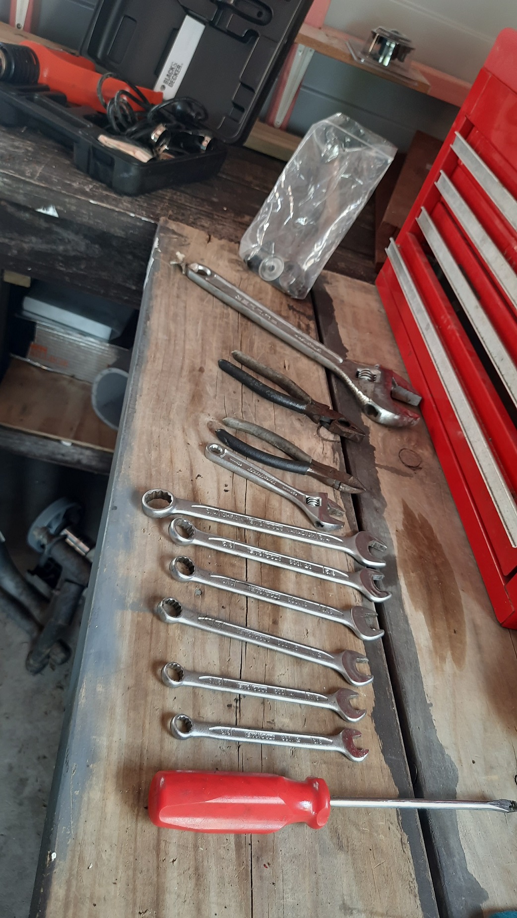
Final paint done, just needs smoothing and polishing then reassembly Also did some research on the Old School tools, they are made by SK tools (Sherman and Klove) Chicago. My Father in Law went through and engraved all of the tools. Don't want those thieving apprentices helping themselves.
1 point
-
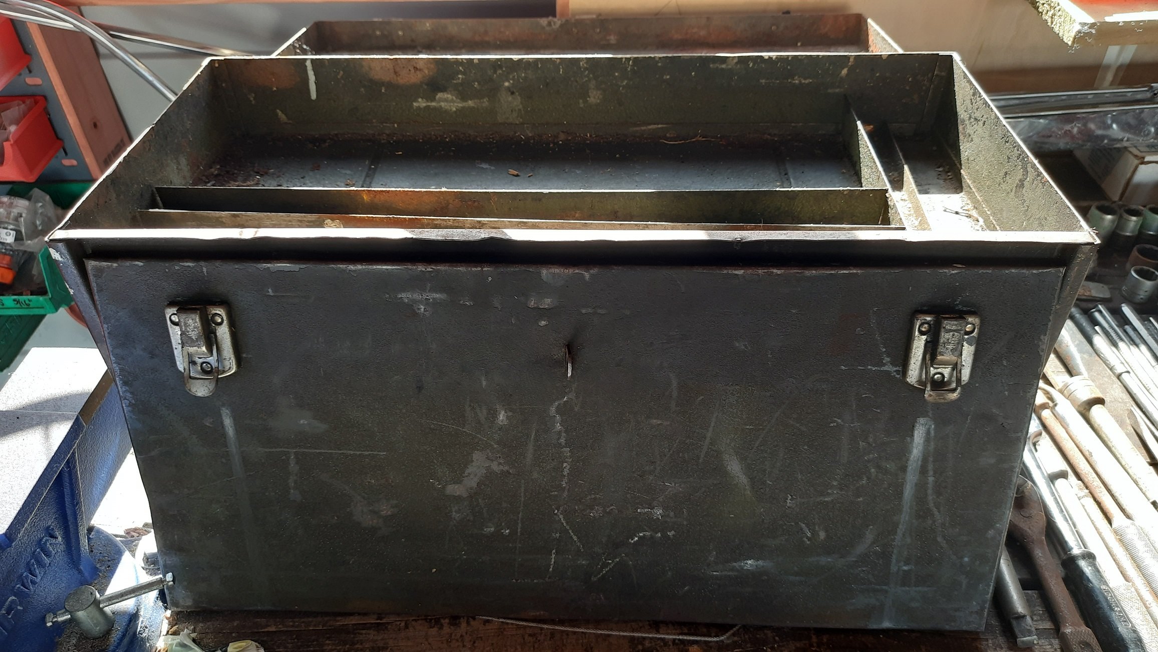
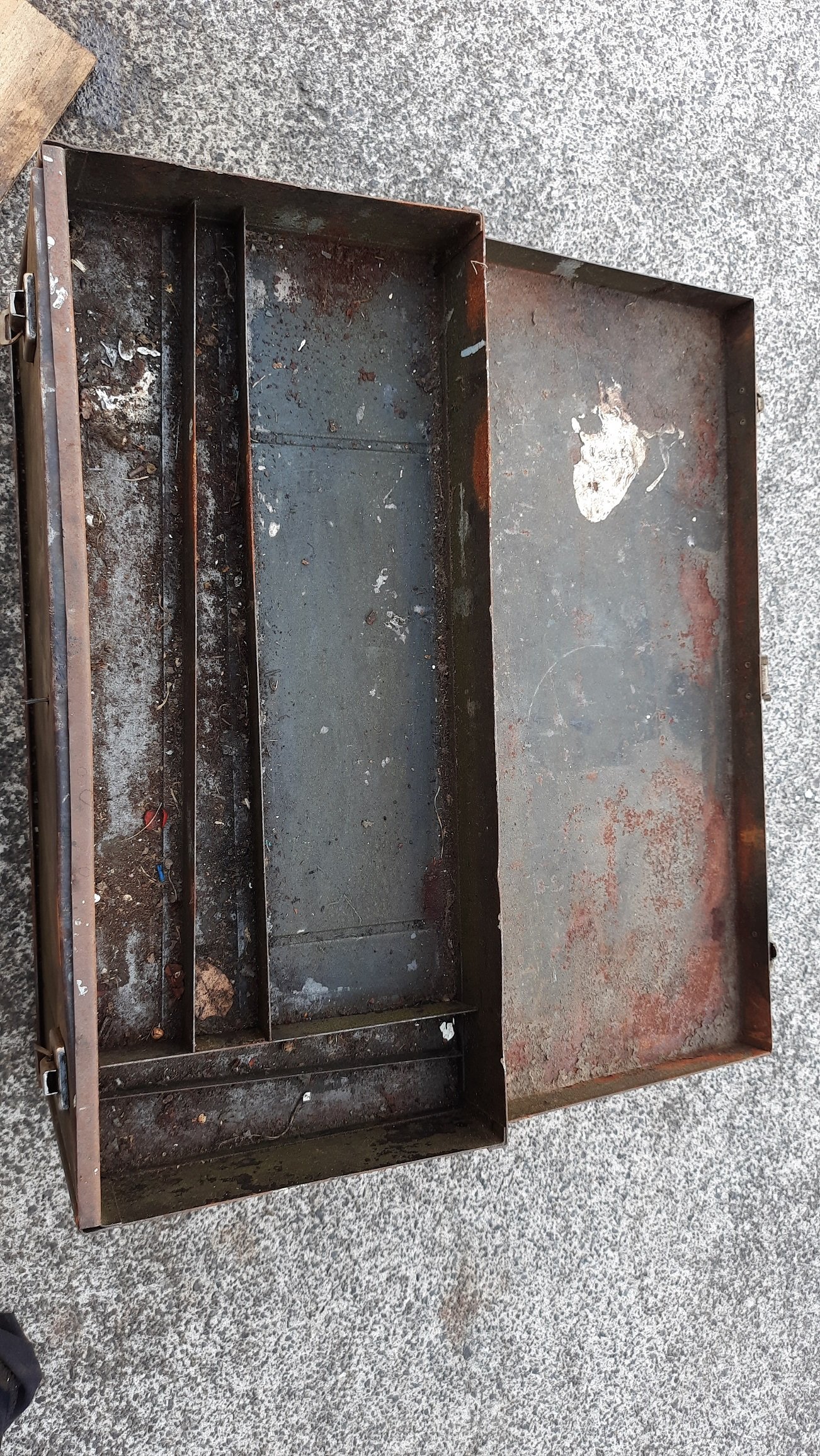
Side project while waiting on the Mustang to be returned. Pretending I'm on the repair shop restoring my Father in law's old tool box. He worked for South Auckland Motors till he retired and this was his. It is from Chicago and must be ancient with probably 60 years of oil and grime to remove. Some cool tools I didn't know existed but wish I did like stubby sockets with a built in uni.
1 point
-
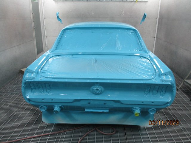
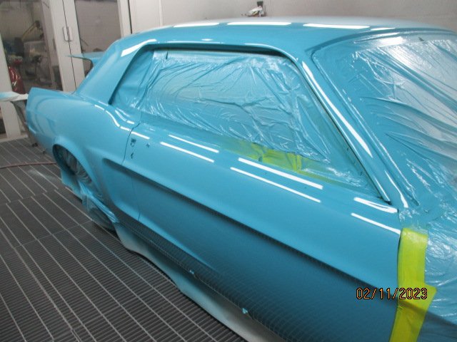
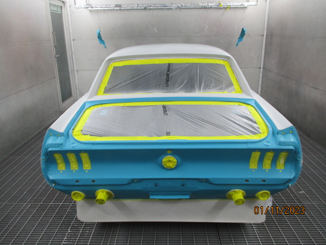
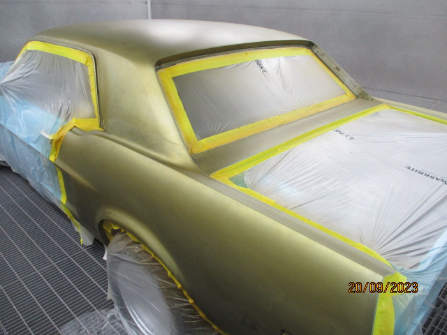
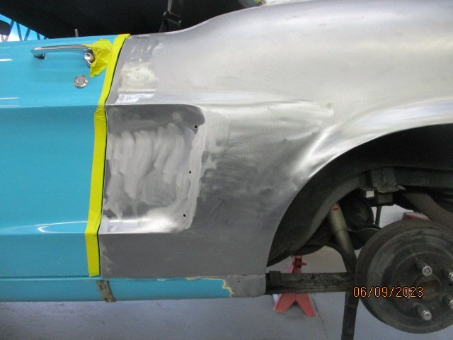
Got some more photos from the Panel beater. Final prime for the main body: Colour in the jams: More areas painted than I thought. The boot gutter and rear valance along with the boot lid are being done. there were a few cracks in the door jams as well that I was ignoring but now they are sorted.
1 point
-
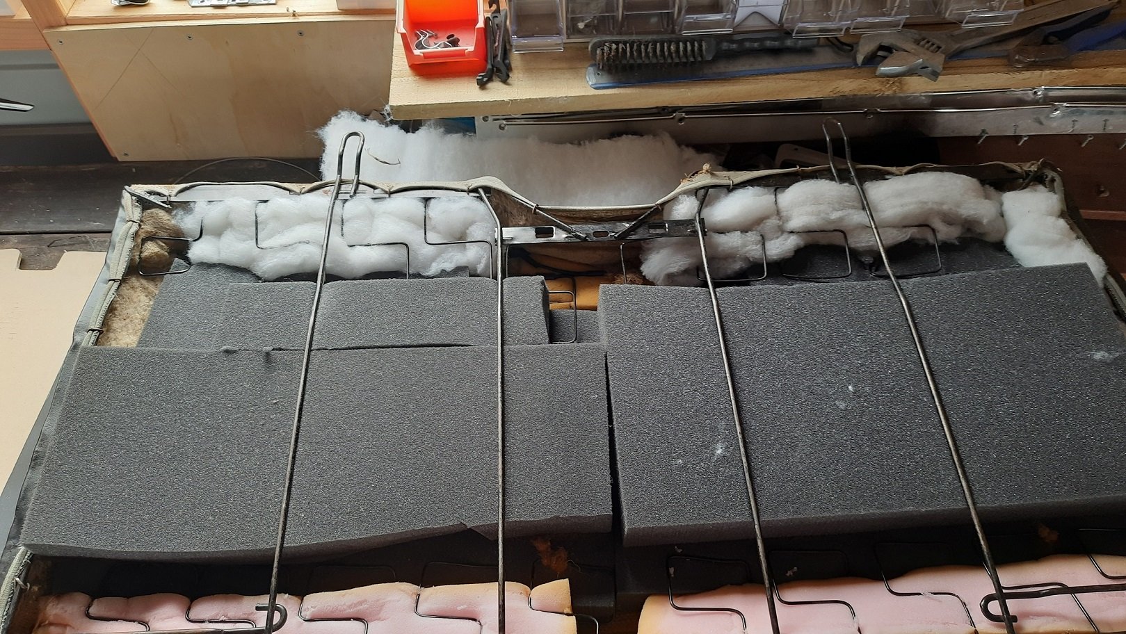
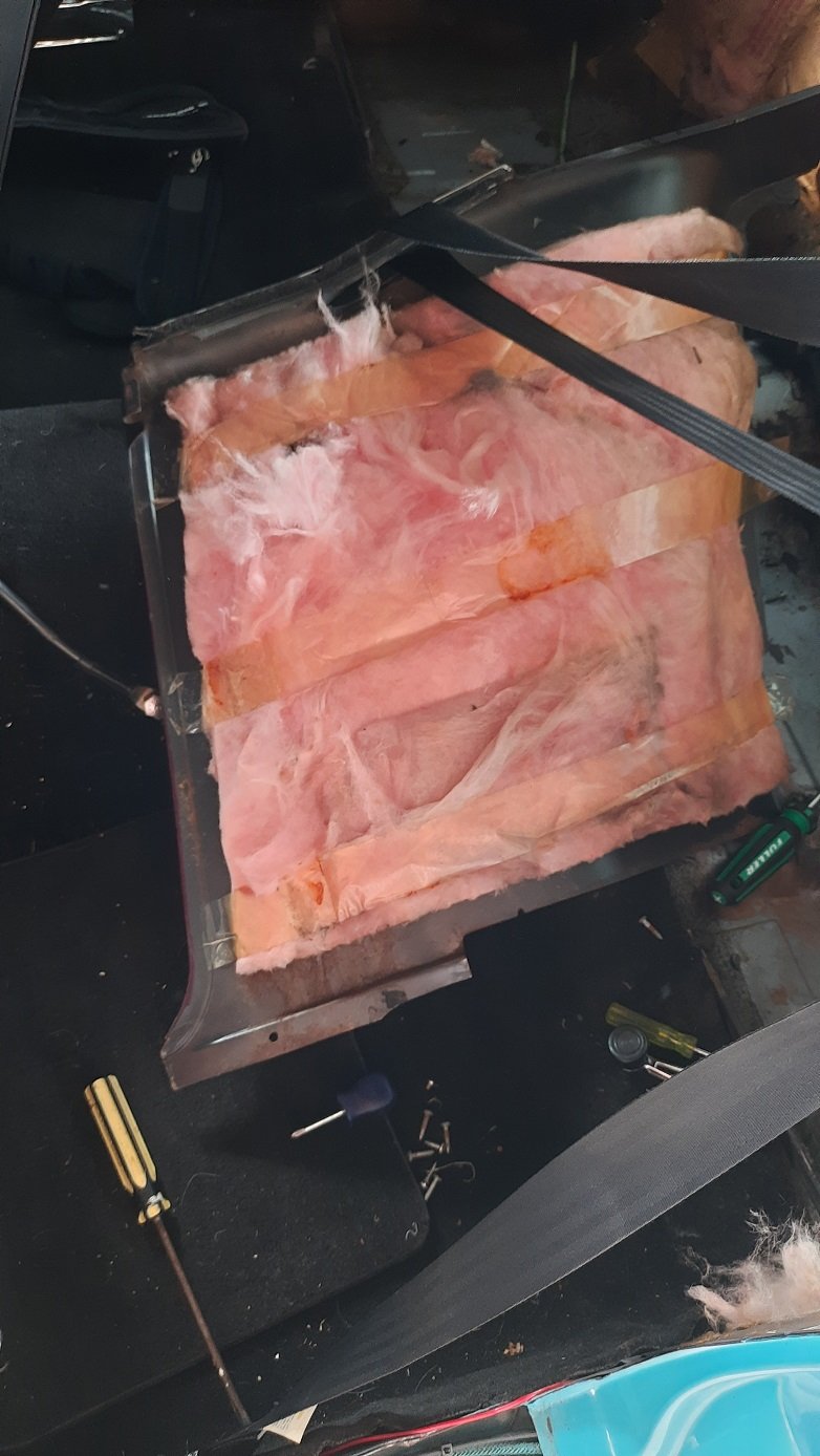
Still waiting on the panel beater but had a bit of a play with some other bits. Gave the rear window regulators a clean and replaced a couple of rollers. There was a ton of gunk to clean off. 55 years of grease and dust. I'll still have to ensure there is room for the inertial reels but otherwise they work nicely. Also removed the pink batts from the rear seat base and inserted some packing foam instead. Still a bit agricultural but actually works to firm up the seat. I'll probably have dynamat under the seat and an MDF cargo divider with underlay behind it so should cut a small amount of noise from the back of the car. I'll see how this turns out in the car once I get it back. Best give the panel guy a call and see how he's getting on.
1 point
-
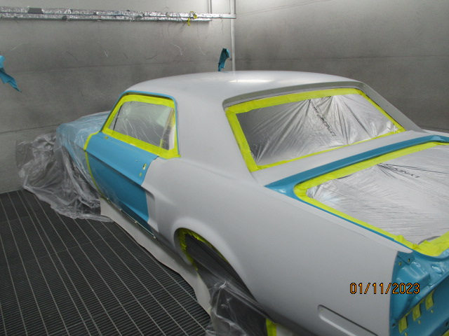
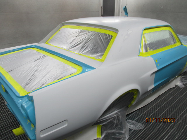
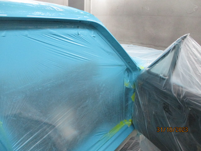
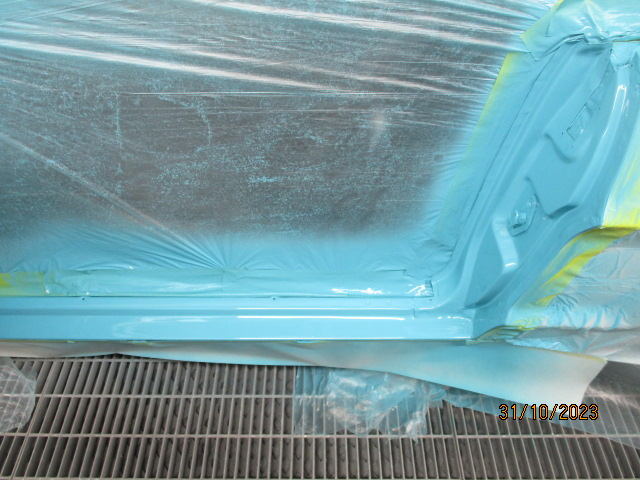
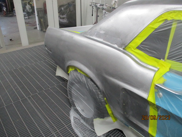
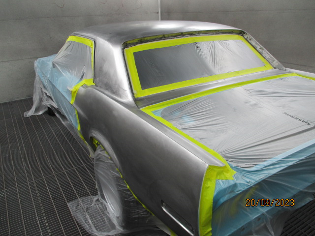
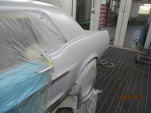
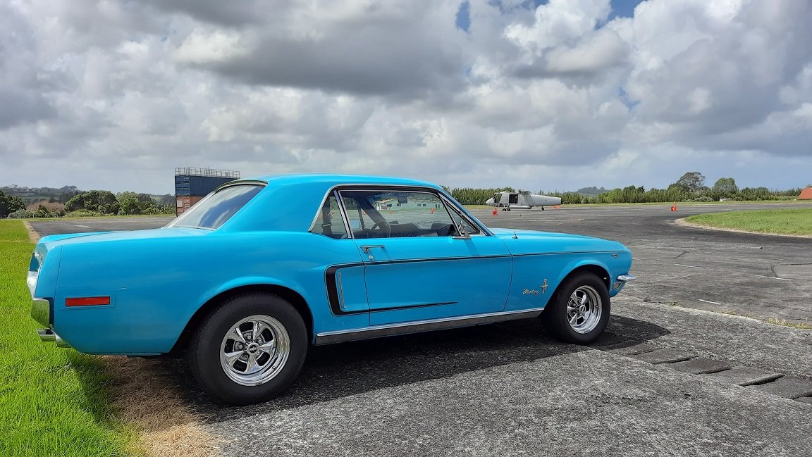
Car is now in the paint booth. the main problem with the car in the first place was poor prep before using filler or paint on lead. It doesn't look like he's used any filler yet but has done some really nice steel repairs. Etch primer? Gold member. and epoxy primer Hopefully some nice blue paint next. I asked for a factory finish not show quality so hopefully he doesn't spend a bunch of time getting every imperfection out otherwise she'll have a really nice bum butter face... The colour apparently came out closest to a volvo blue. Not sure which and I think it needed more white to match the car so is likely some odd concoction they mixed up last time it was painted.
1 point
-
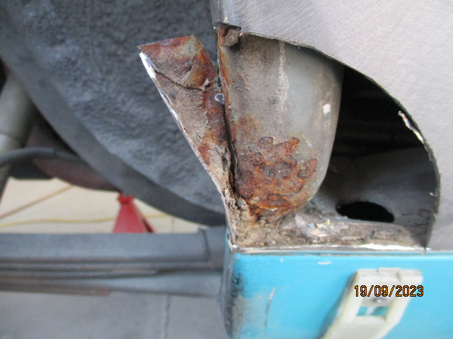
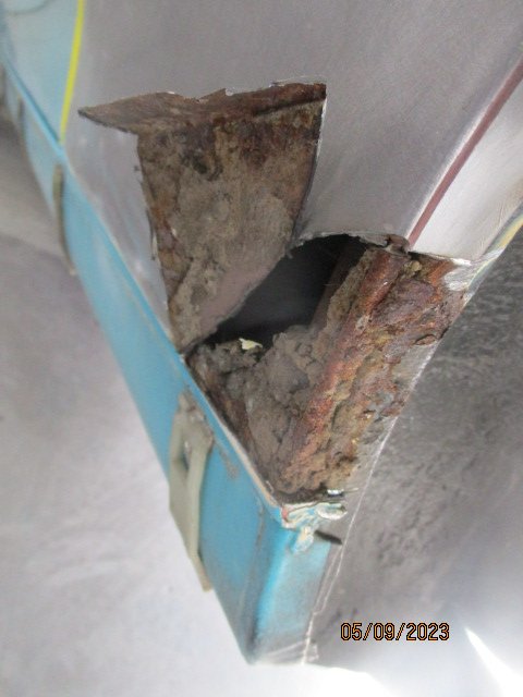
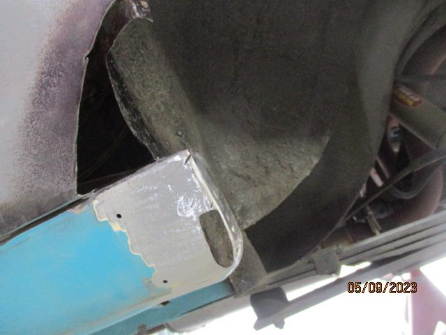
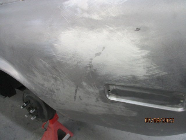
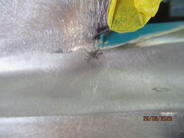
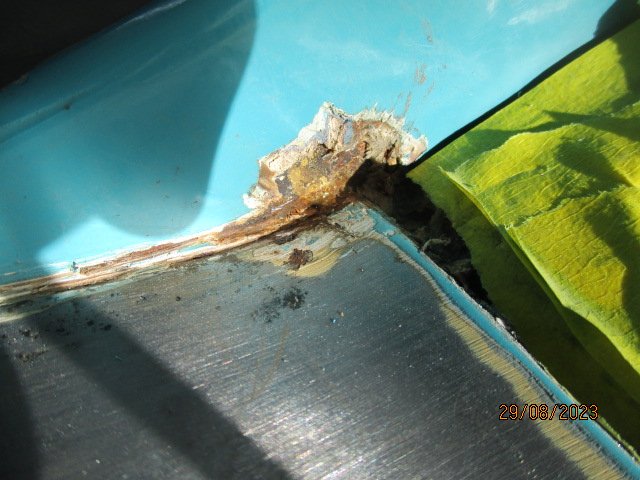
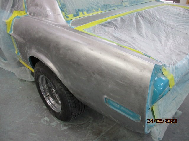
Front of right rear wheel arch
1 point
-
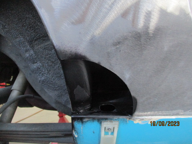
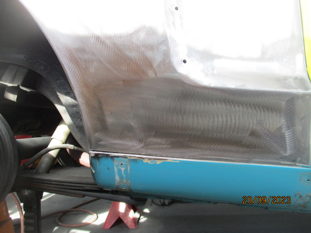
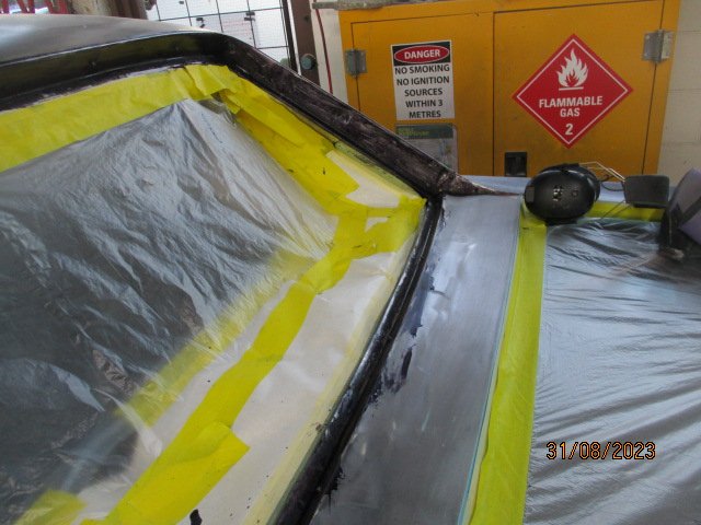
More repair photos from the tin basher No more crud or 'bullet holes in the side panel. Welded up the extra trim mounting holes as well. Same at the back Rear window crud removed And treated I'm guessing it will be ready sometime next week, then I'll have to pay the bill.
1 point
-
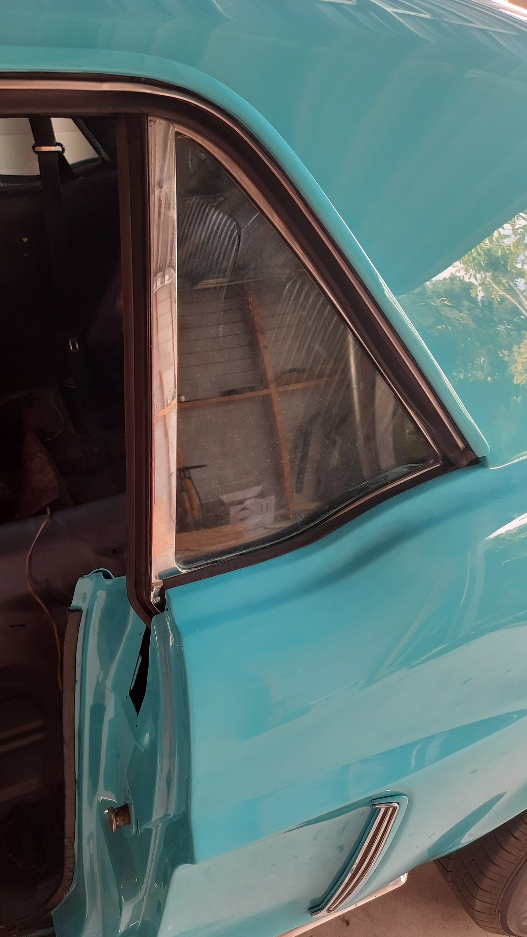
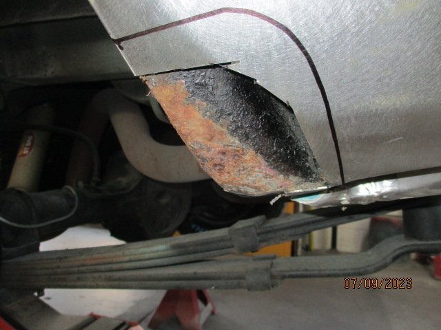
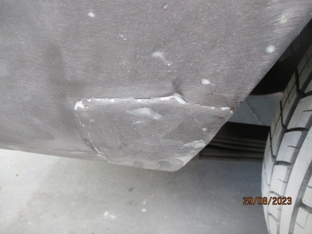
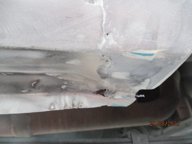
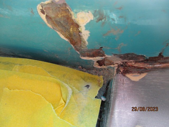
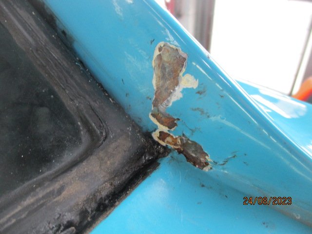
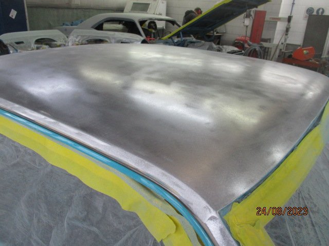
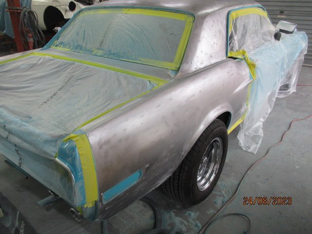
Got the report and pictures from the panel beaters: Most of the paint cracking is loose filler over lead joins on front A’ pillars and rear quarter sail panel areas. - Roof is good only some small dents with filler repairs. - Gutters have heavy rust surface rust, which we have removed all old seam sealer and rust treated. - LR quarter panel- Old panel pull holes were just filler filled, need dressing up and welding - Lower front wheel arch needs rust repair - Wheel arch needs a little hammer up to true up edge before re filler work. - Rear lower panel area was heavily filled needs a hammer up before refinishing - Quarter window corner needs weld up, stress crack area. Will need to remove window seal and channel out. - Right Rear quarter- Front area need a hammer up before re filler work - Rust repair lower front wheel arch area - Old patch repair I recommend removing old patch in this area and replacing. - Rear window area- Needs rear window removed due to rust in lower rear corners and seam area SUMMARY: Apart from some findings that need attention, overall body is great for its age. The car has been stripped to bare metal at some stage, with just filler work over bare metal letting it down in areas. Should be an easy fix and proceeding nicely. Going to hit the bank balance a bit more than I planned as the insurance is only paying for a blend not a respray but they will at least save me about $2k.
1 point
-
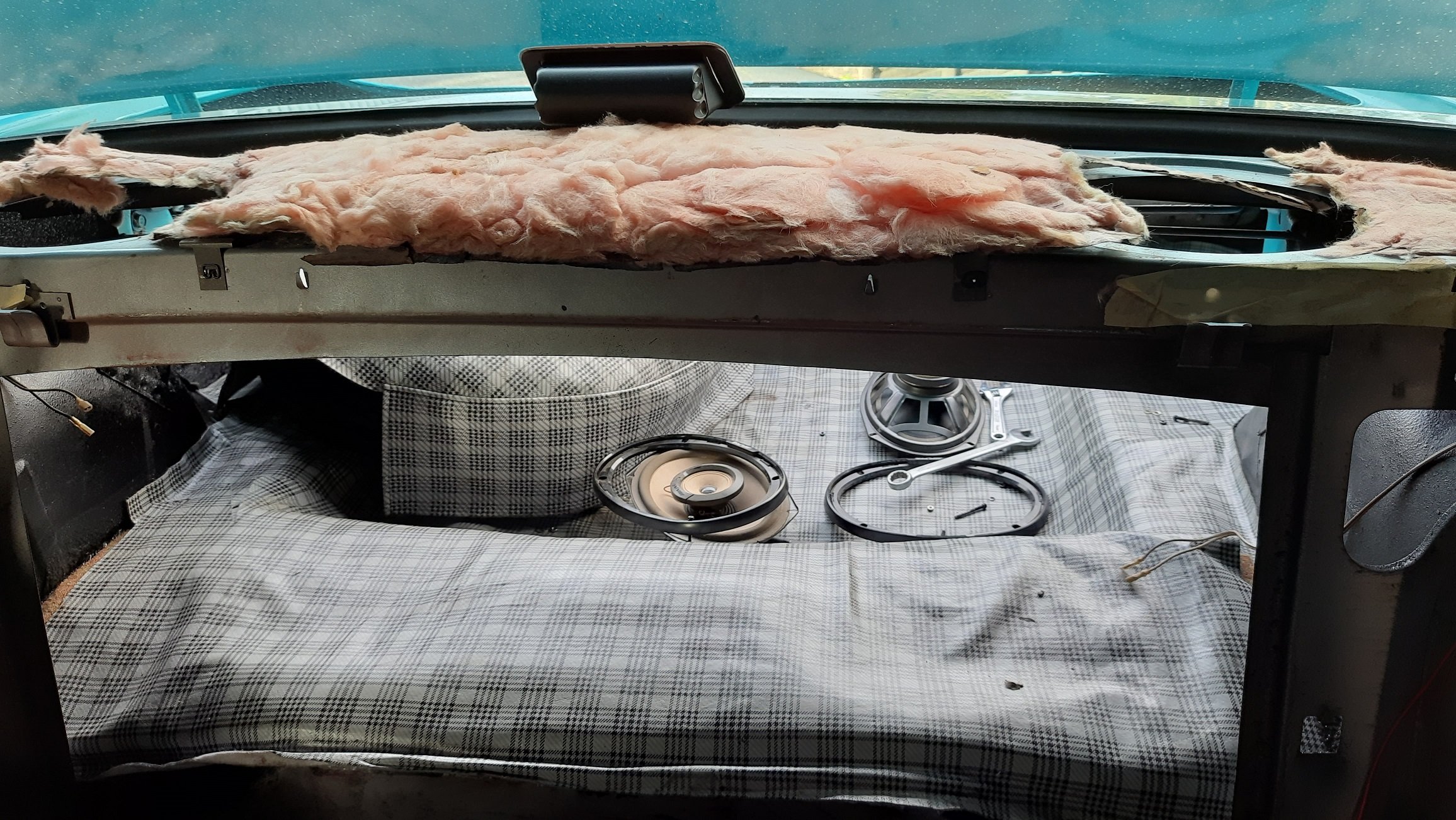
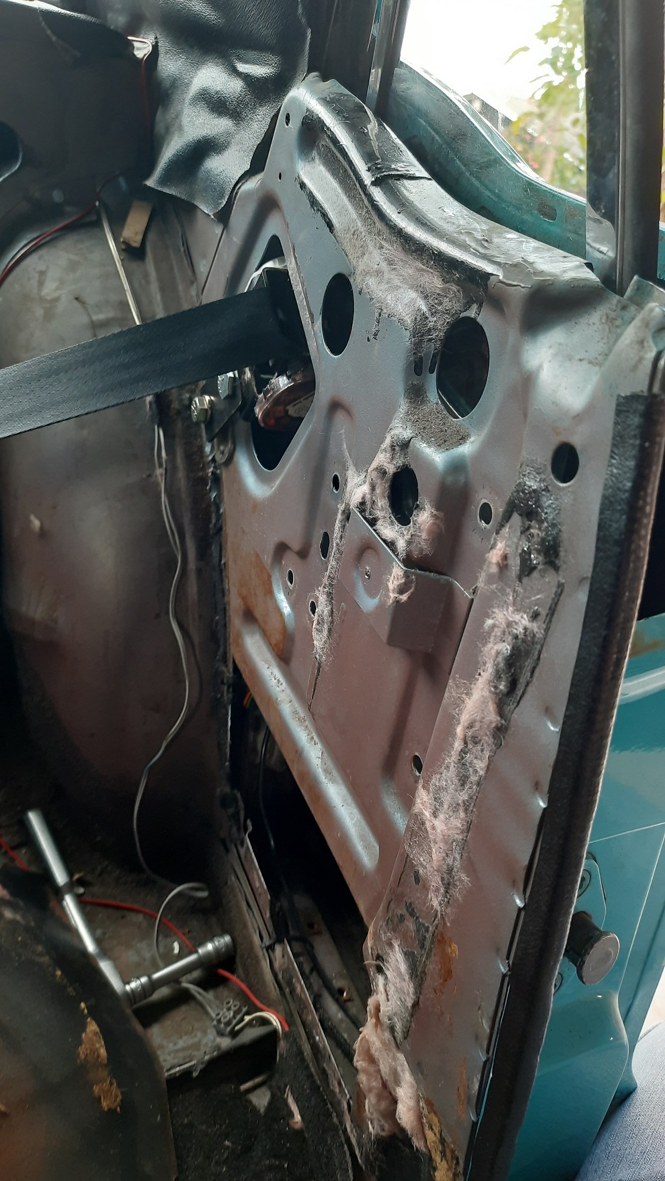
Started pulling a few things out prior to taking it to the tin basher for the panel and paint repairs. I took out the rear seat, parcel tray, and trunk divider as both were just cardboard and shit. A previous owner loved his pink batts, not sure if they were doing much but it's in the bin now. I kept the parcel tray for now just in case my new one is too thick but hopefully I'll ditch it. Also took out the speakers but I may just end up putting them back minus the grills. I made new panels from 9mm MDF. The parcel tray will get covered in black vinyl that I have left over from doing the same on my Fairmont. I may put some speaker mesh on the tray itself rather than the ugly grills although I will lose a bit of the 90's 6x9's bro look. I'll get some proper underlay for both I think. Next I took out the sail panels, more pink stuff here too. I don't know the sound isolation properties of Pink Batts but since there is a lot of tin resonating I doubt it did much. Got a good look at the seat belts. I'm not sure if the car came with lap sash belts but I'm pretty sure the inertial reel is after market. Bit sneaky it hasn't been certed but looks pretty legit. Only problem is it blocks the window mech so will need tweaking so the window goes down. Took the window out so I can service it and get it working. It is actually really smooth so should work ok if not contacting the belt reel. Not sure how I'm going to get it all back in though, it is a bit fiddly. Will give the cavity a good clean out, already got some crap body sealer and sand out. I can see why I have a bit of crud under the paint on the outside as there was a bunch of sediment between the inner guard and the outer sail panel. I may wait till the paint is done to finish the inside just in case he cuts anything out. Looks pretty clean otherwise. Will give it some spray in sound deadener and fish oil once the paint is done.
1 point
-
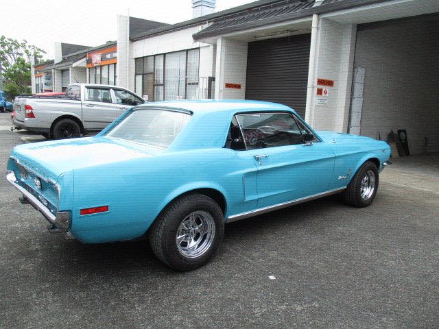
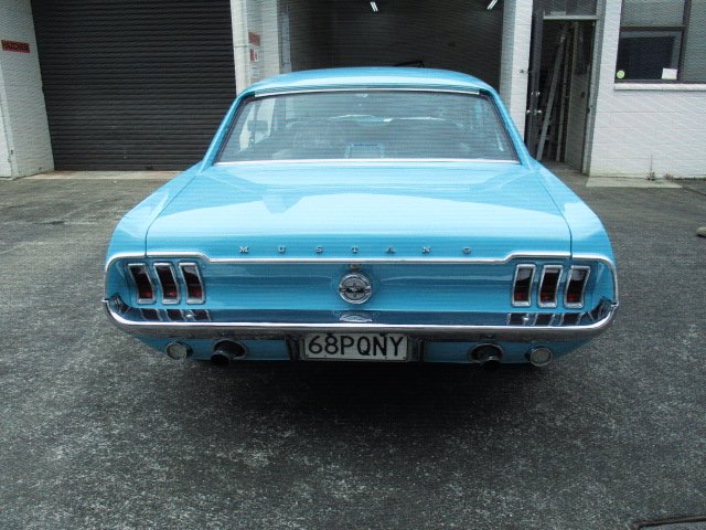
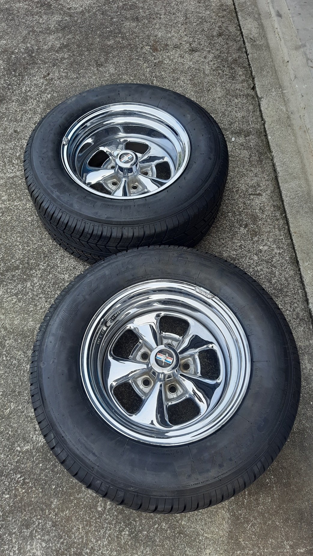
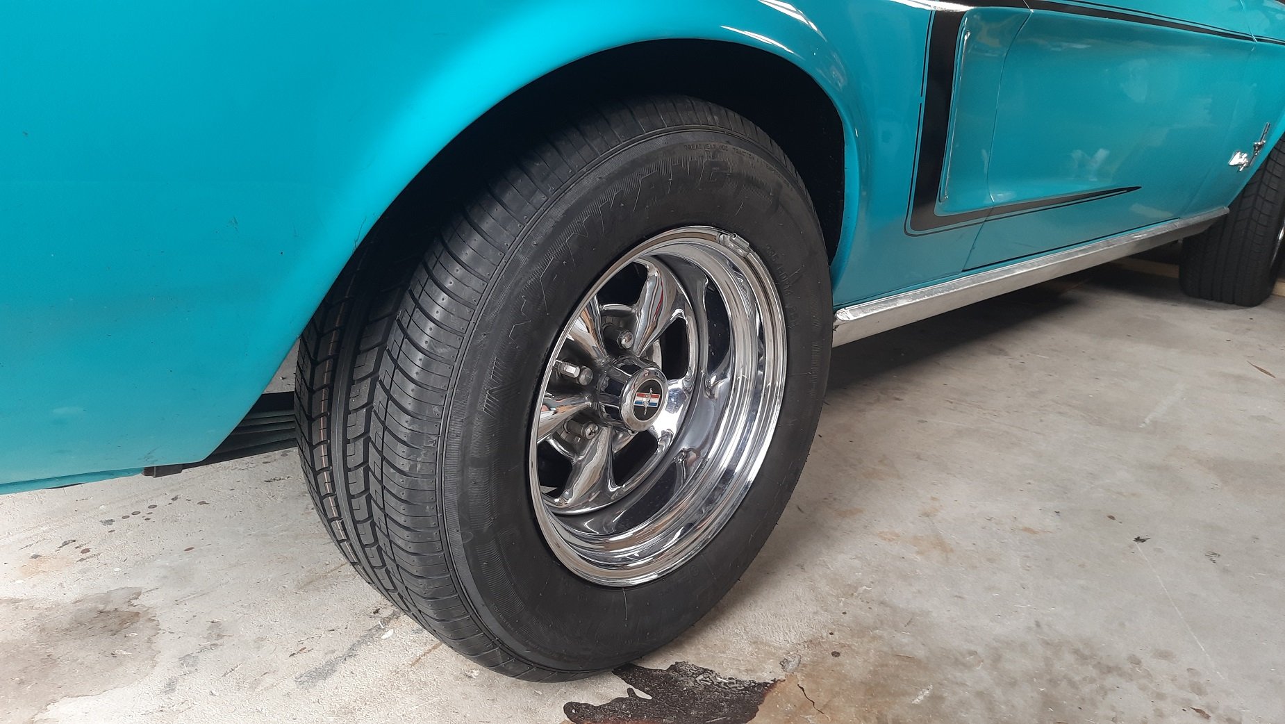
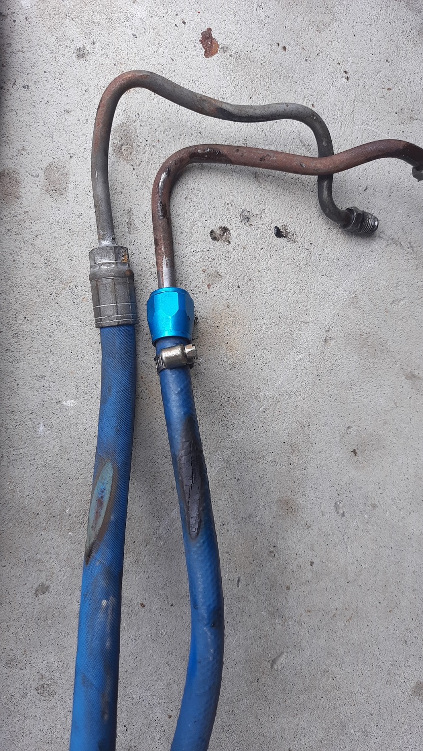
Got some new tyres to match replace the old cracked and damaged Firestones. Got Nankang 235/60R14's, down one size from the old tyres and matching the front. These ones should pass a warrant. Hope the warrant guy doesn't check too hard, I think the power steering lines are still leaking and there might still be a header leak. See how I go.
1 point
-
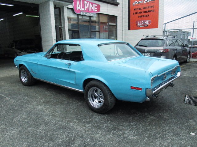
Took the Mustang to Alpine Panelbeaters to assess the scratch on the rear quarter. Can't vouch for their work yet but seem like good people. Had a nice Challenger fully stripped and a couple of other interesting cars. Will have to re raise my claim with AA Classic. Sounds like they will have to repain the whole back half of the car so am getting a quote for repairing all the other issues first. Hope I can swing that with the insurance. Had a brief look at the headers too. Easy to see how they could leak, the flange is almost like a collar holding the pipes in rather than a flat flange. Will also be interesting to see if I could even get them off with the whole system being rigid.
1 point
-
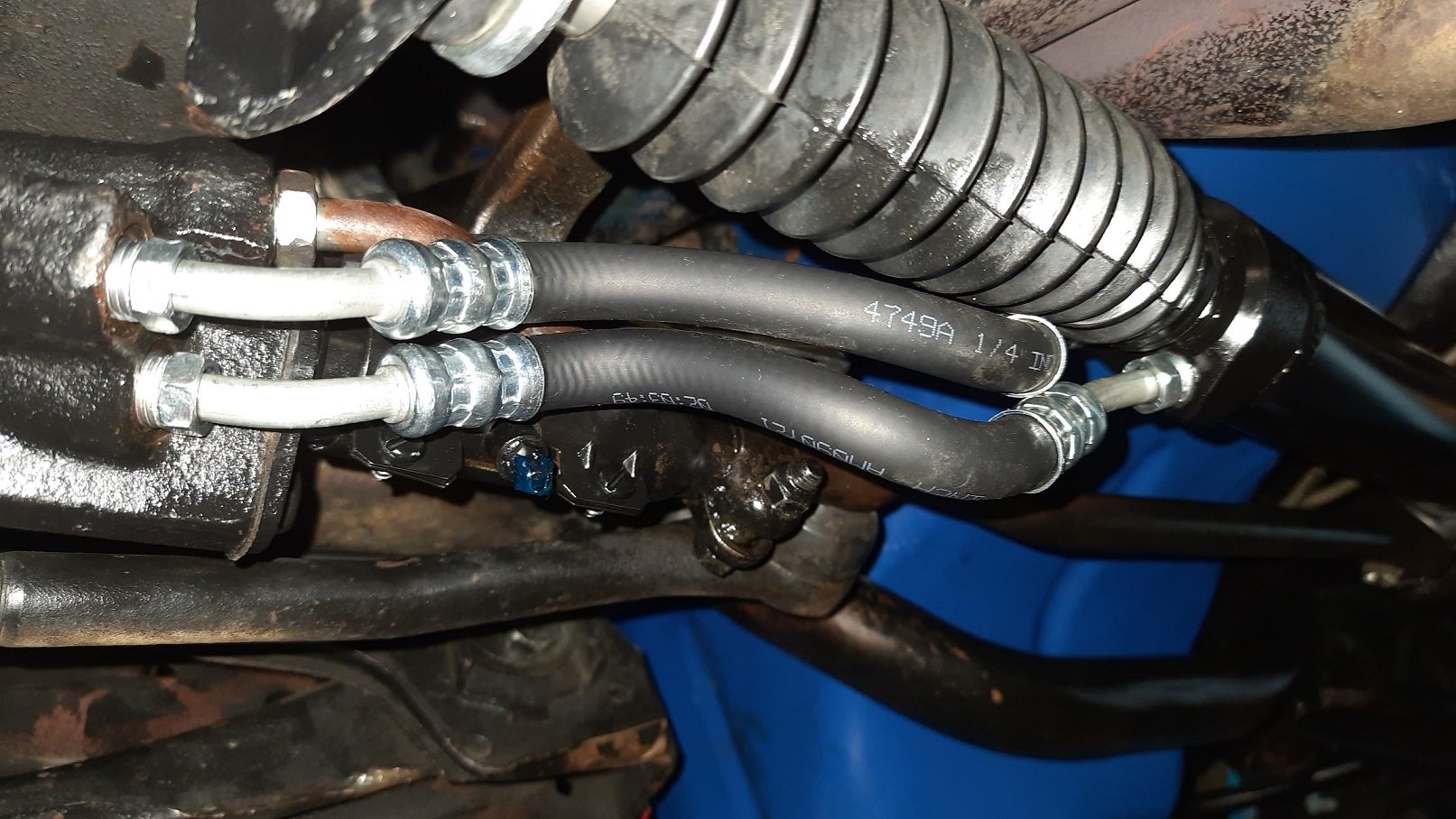
New lines fitted, seems dry now. Need a wheel alignment now. Need new rear tyres anyway so will get that done at the same time. They also said I had an exhaust leak from the left header gasket, sound familiar anyone? Might need to have that off and replace the gasket and fire on some gasket goo. I'm tempted to fit some flex joints behind the headers as well since they are solid welded all the way back. No flanges anywhere.
1 point
-
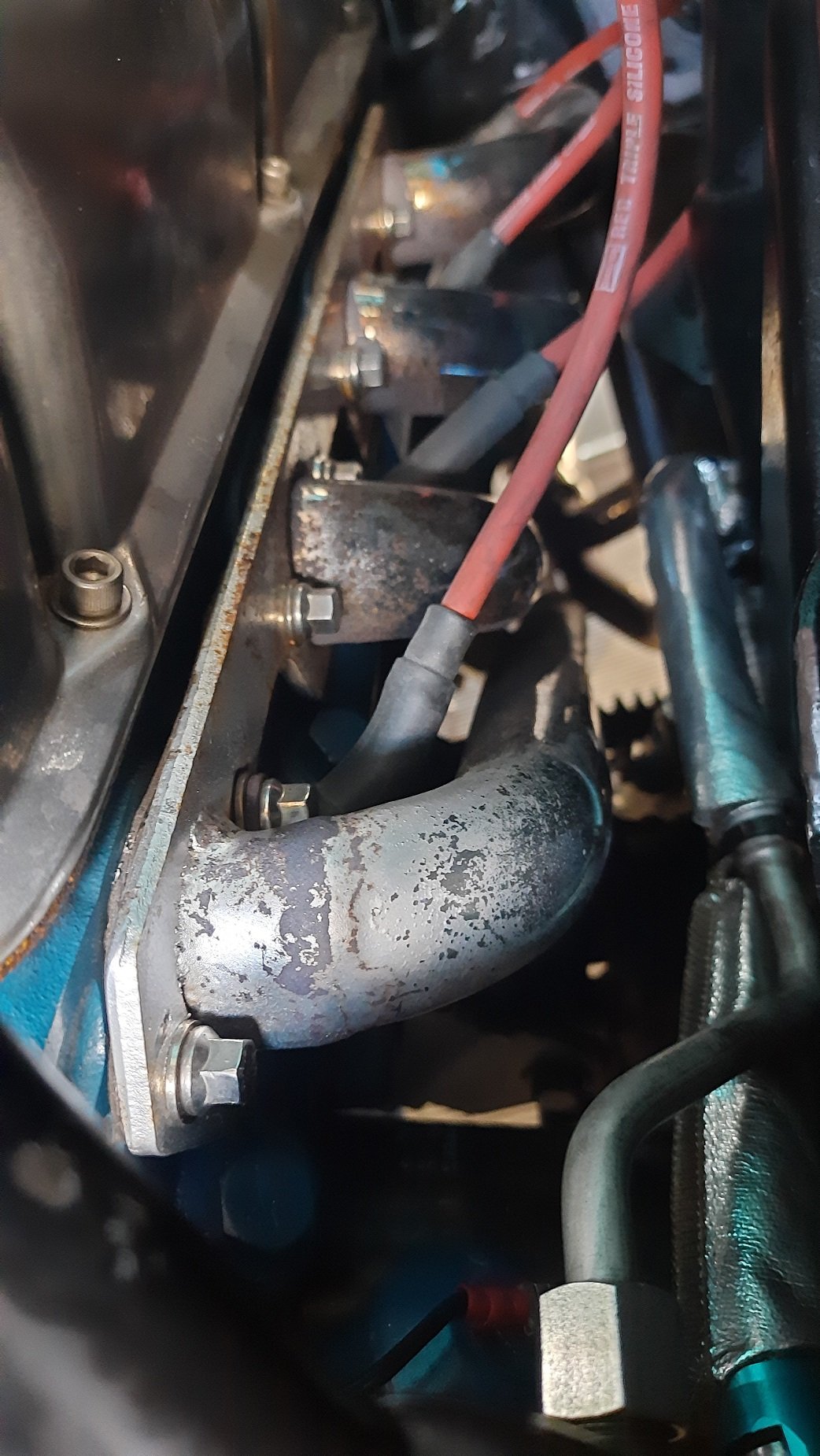
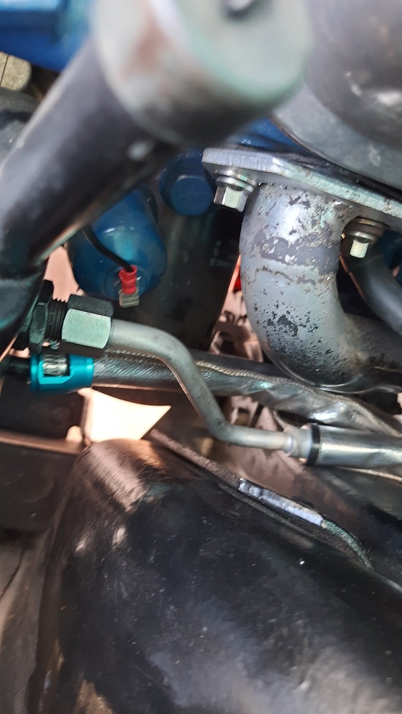
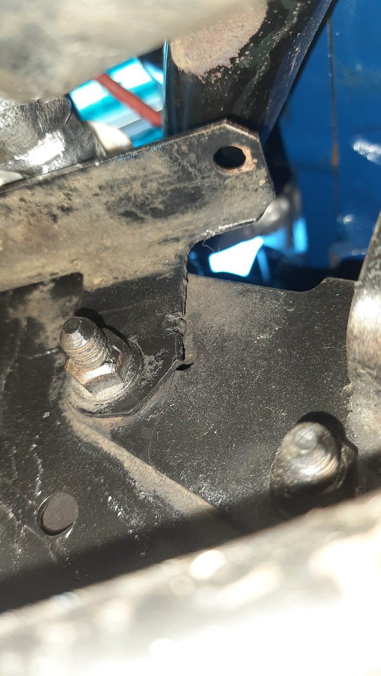
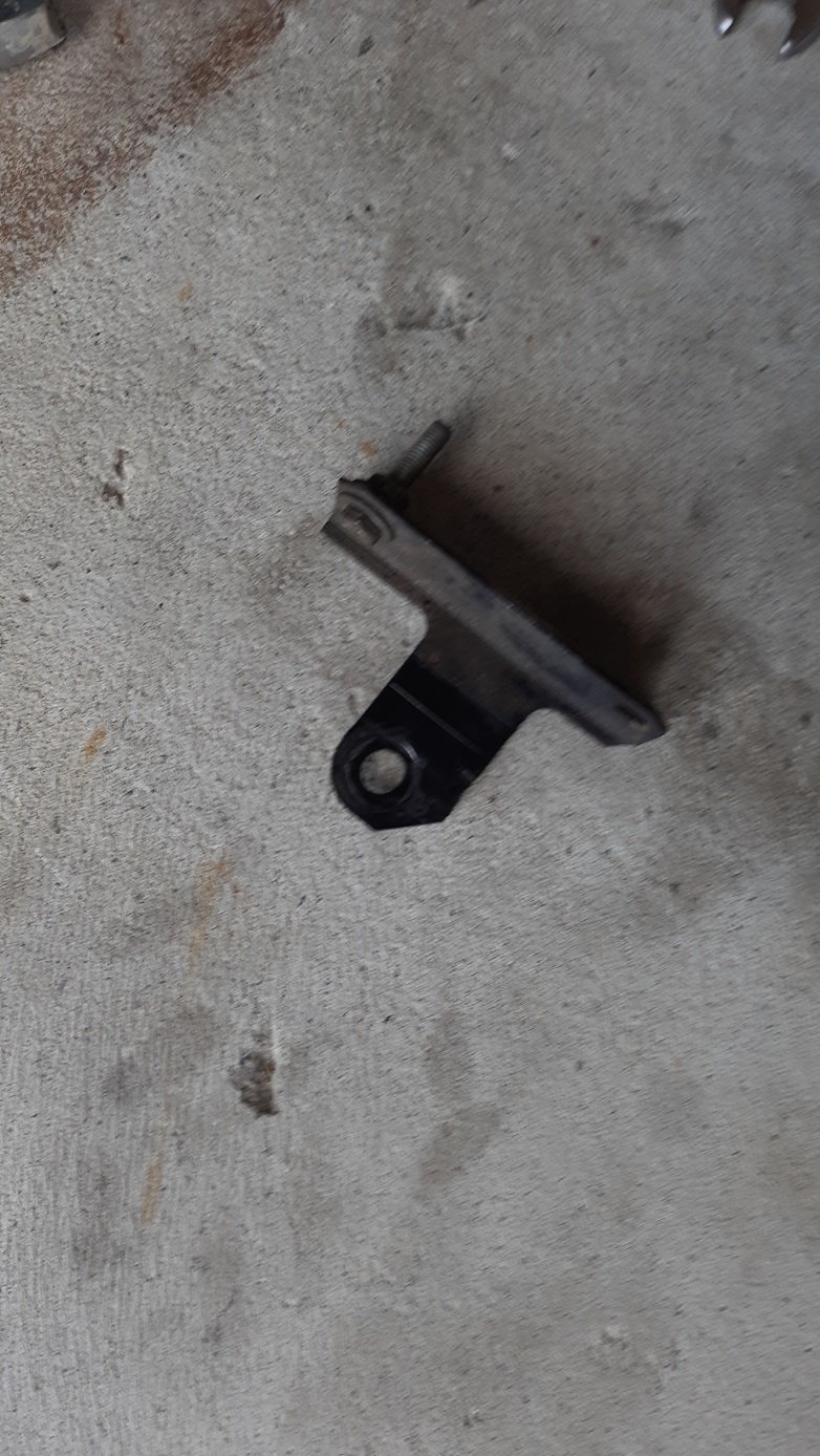
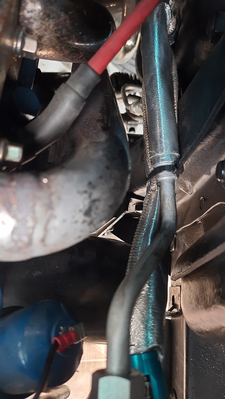
Before diving back into the steering I thought I'd revert to what I know, wiring. The temp and oil pressure gauges are dodgy, they may work but I can't really tell. The terminals looked shite so I replaced them I decided the Random bracket on the engine mount that does nothing was getting in the way of the power steering lines Now gone Dunno what that did but the car is not lighter and more efficient. It freed up enough space to lower the lines a bit below the headers and with some manipulation I managed to realign the hard lines off the power valve. Add a zip tie and now I have more clearance. I think the pressure line is still a bit long and hits the header at the bottom on full lock but the heat sheath will save it for a while. There are also a few leaks and the lines from the power valve to the ram still need to be replaced but I might take it in to a pro to check everything and do an alignment once finished. I also need to replace the trans shifter seal so I might get that done at the same time. Lucky I live pretty close to the shop.
1 point
-
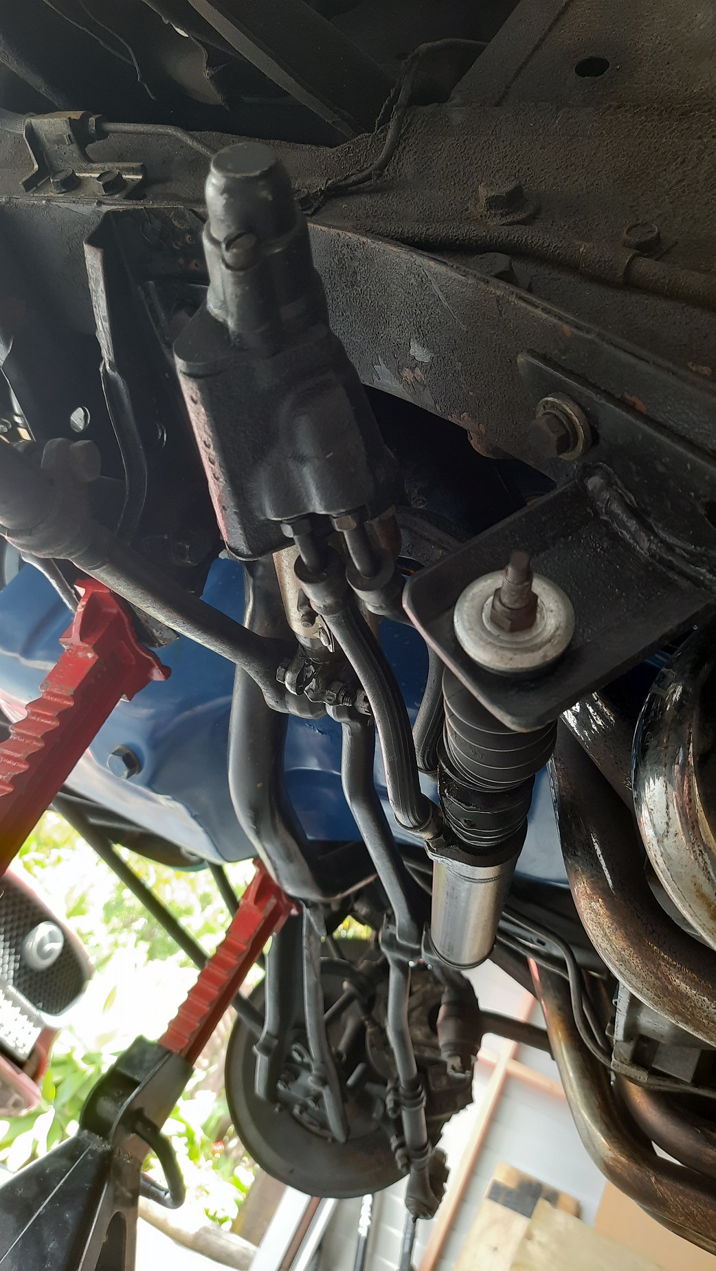
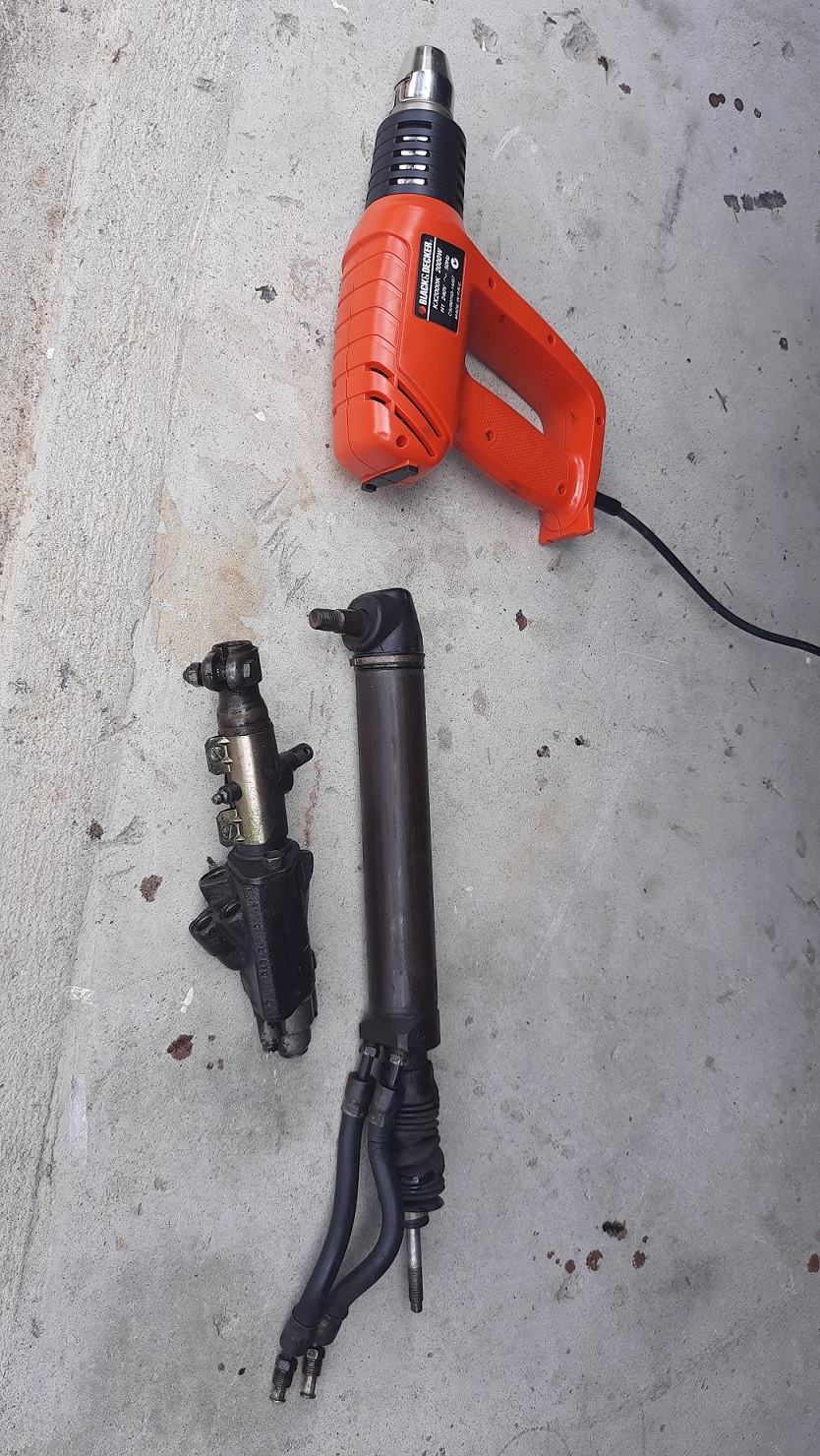
First step, jack your car... These items were leaking from everywhere so need to come out. Had to buy a tool for the steering arm, hit it with a hammer and off she comes The ram was a bit stubborn, hammer didn't work had to use heat. Lucky didn't need to move up to a torch The lines get too much heat. From the header I think, not the hot air gun, I'm not that gash. All the tools required because Ford. Need to take it in to a power steering specialist now, I'll hopefully get new seals, lines, and bushes. I might replace some other steering and suspension bushes while it is up in the air.
1 point
-
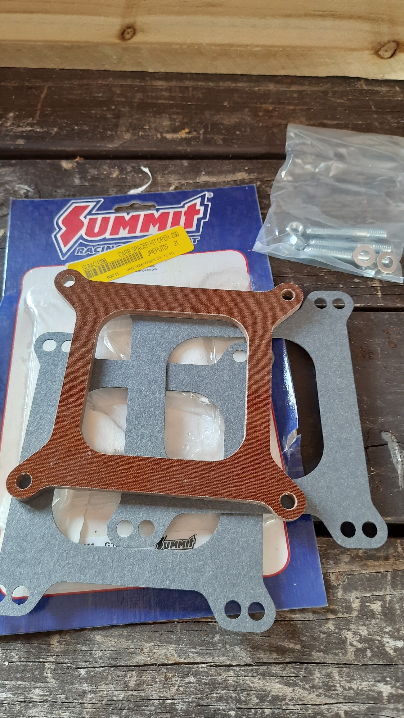
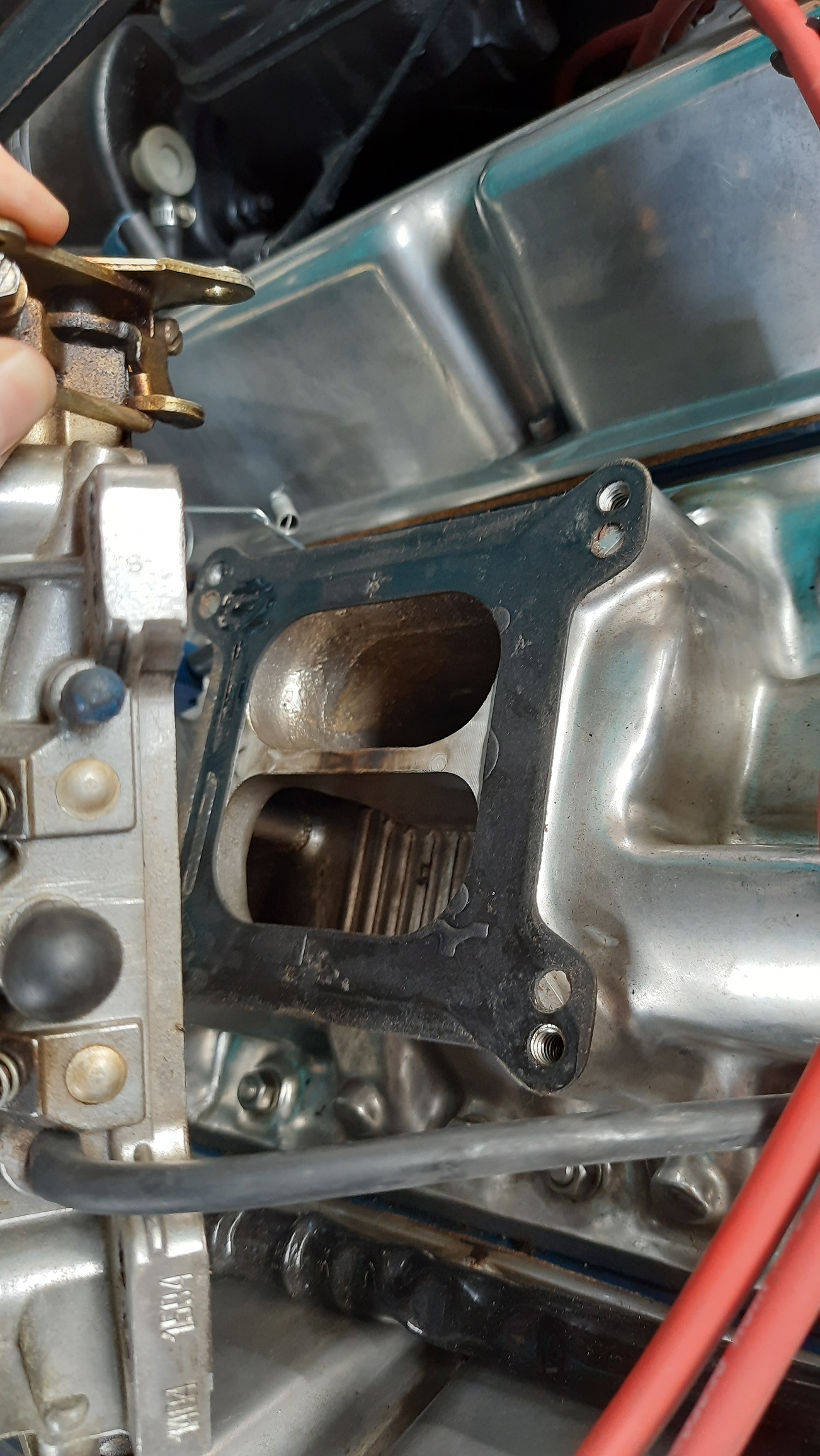
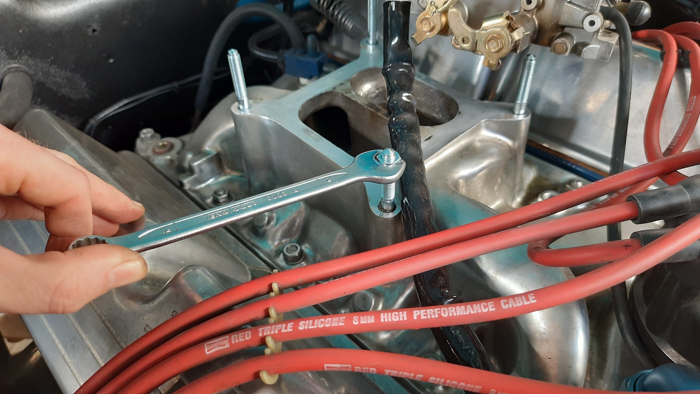
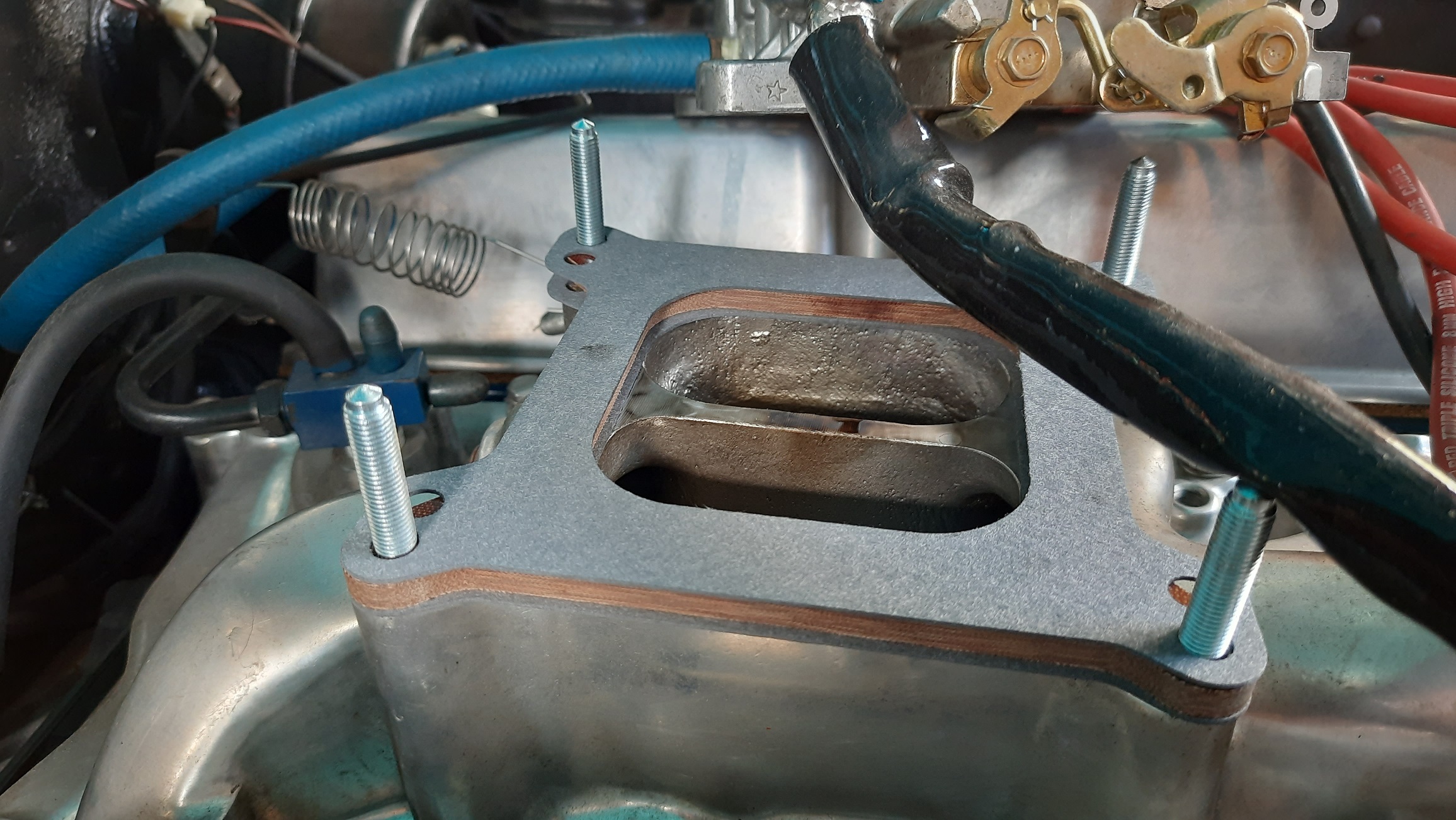
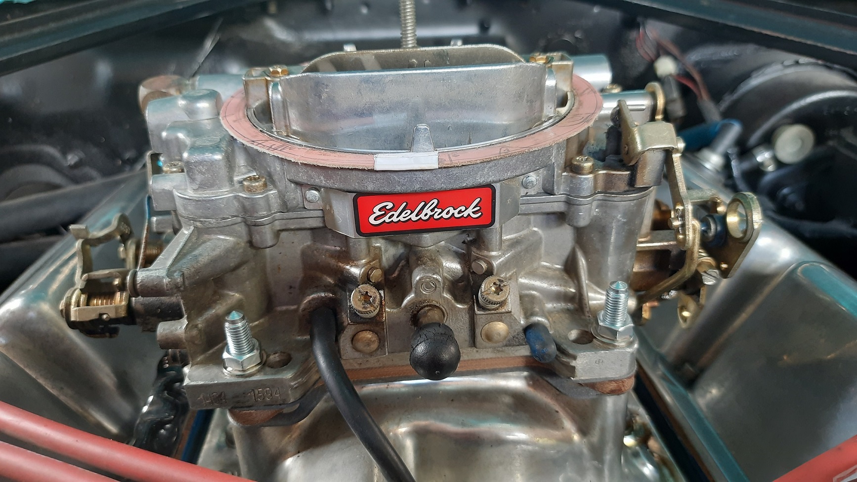
Finally got my carb spacer from summit, it got caught in customs. Not sure why, I didn't get charged anything so maybe just adding FAF. Good chance to check out my performer clone intake. I was lazy and didn't disconnect the carb, just unbolted it and moved it to the side. Spacer kit comes with studs, used the locknut method to screw them in and did them up to 5 wrist pounds Finished product. 1/4" extra height which fits under the bonnet with about 1/2" to spare with the current air cleaner height. Hopefully this keeps the carb a bit cooler and maybe might add a tad more airspeed and the 1 extra HP will make all the difference. Not much I can do about ambient air temp so that will always be hot on a hot day in traffic.
1 point
-
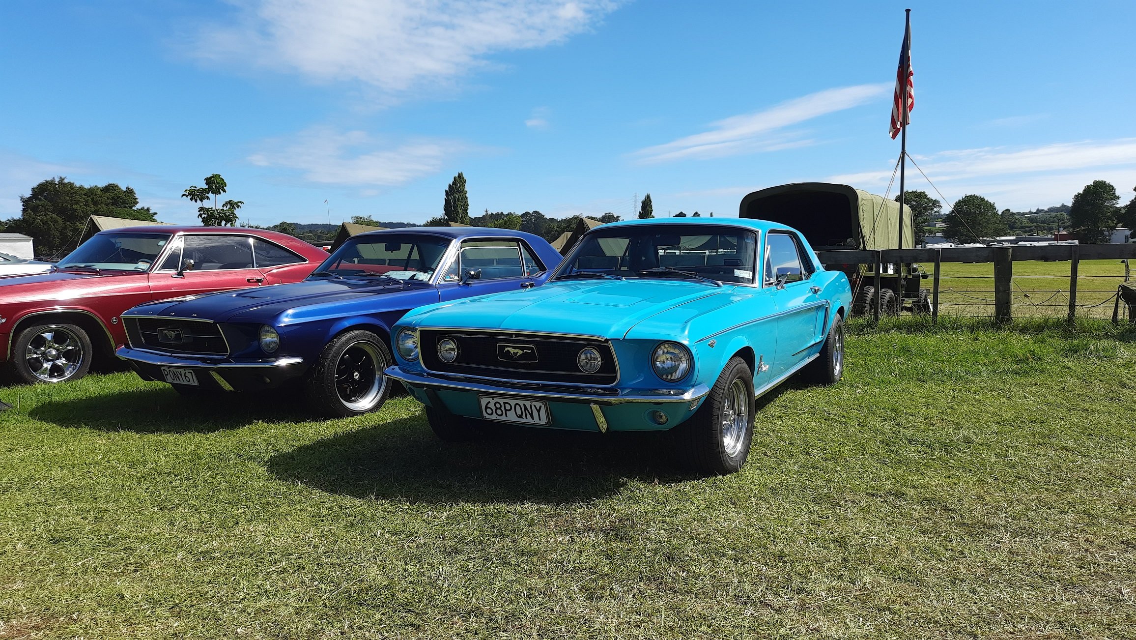
Made it to Kumeu on Sunday. Light turnout compared to Saturday but did manage to find the Mustang's older brother.
1 point
-
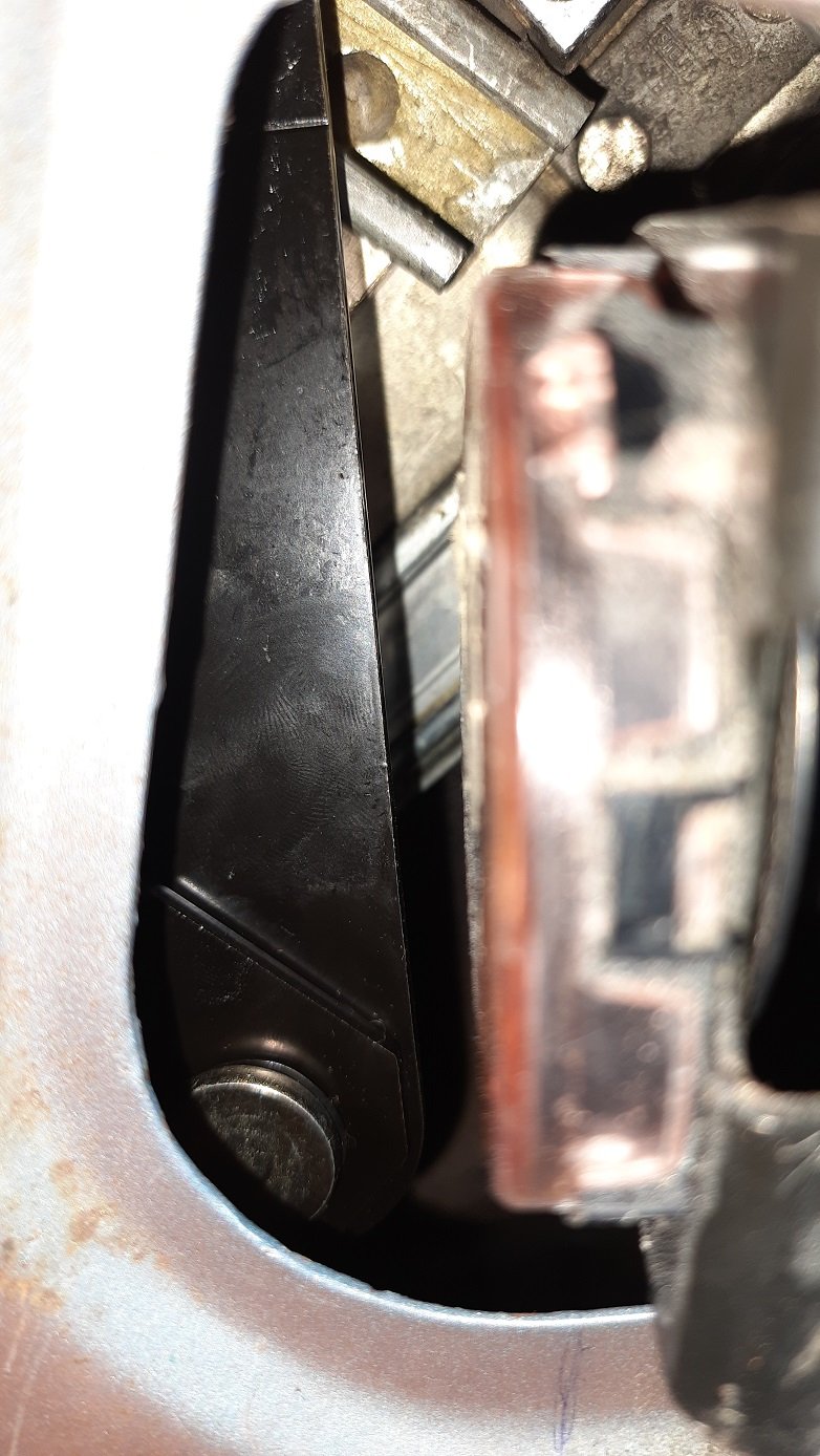
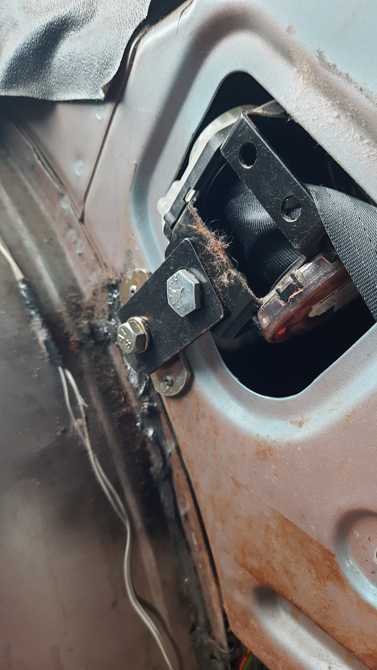
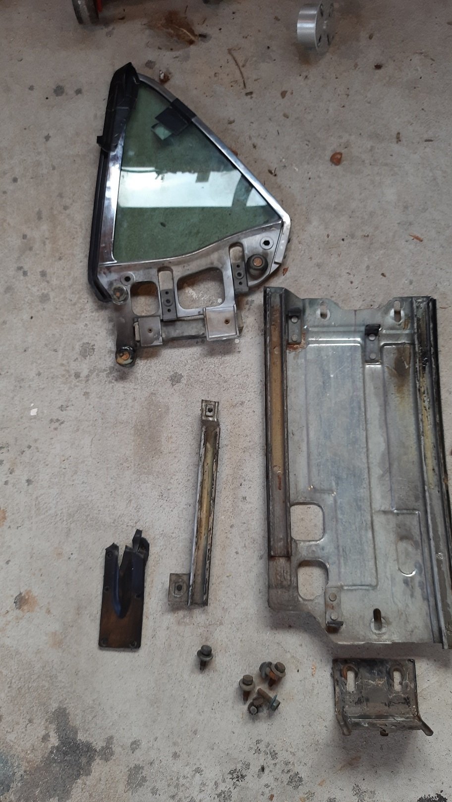
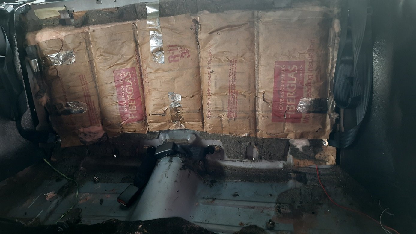
Decided to have a quick look at why the rear windows don't go down. Started by pulling out the seats and then side trim The previous owner really liked house insulation, not sure if it is achieving much The side panels are actually metal. Mustang guys probably knew that but news to me. I can see why you'd insulate it but dynomat or similar would be better. Later project. Can see how the window system bolts in and also (badly focused) the inertia reel. What you can't see is the rollers on the bell crank came off the fixed and moving sliders. Still can't see it here but it was wedged at the top behind the inertia reel. I think the belts were probably fixed and inertia reels added and there may be an interference problem but getting the rollers back on proved to be a bitch. I got one back on the window but not the fixed slider and then removed the roller to see if I could set that first and probably made things worse. I probably need new rollers and to actually remove the system and clean it all up. I could then also clean up the red stuff inside the panel while I'm at it and cavity wax it all. I think there will need to be a take two. Did manage to slide the window down by hand though. Secure as.
1 point
-
Took it for a run at our tarmac sprints the other day. Little autocross and 1/4 mile. No timing gear so no idea on times but did a nice wheel hopping one wheel peel with about 85mph at the finish. Must have looked like a mad man spinning the wheel in the autocross, not really suited for that but fun. Have to assume it is all good as none of the gauges are reliable. Tried to track down some action shots but all I've got is this:
1 point


.thumb.jpg.570970b401ac8d26ce9af7c1bf2bd8cd.jpg)


.thumb.jpeg.e0a4bff61111e0c8c7396950fcc94da1.jpeg)


This leaderboard is set to Auckland/GMT+12:00