
Leaderboard


Popular Content
Showing content with the highest reputation on 09/01/23 in all areas
-
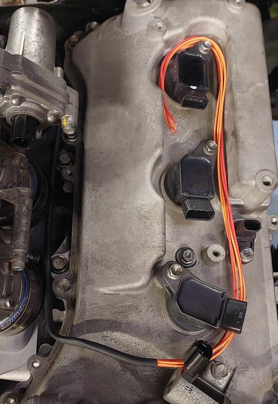
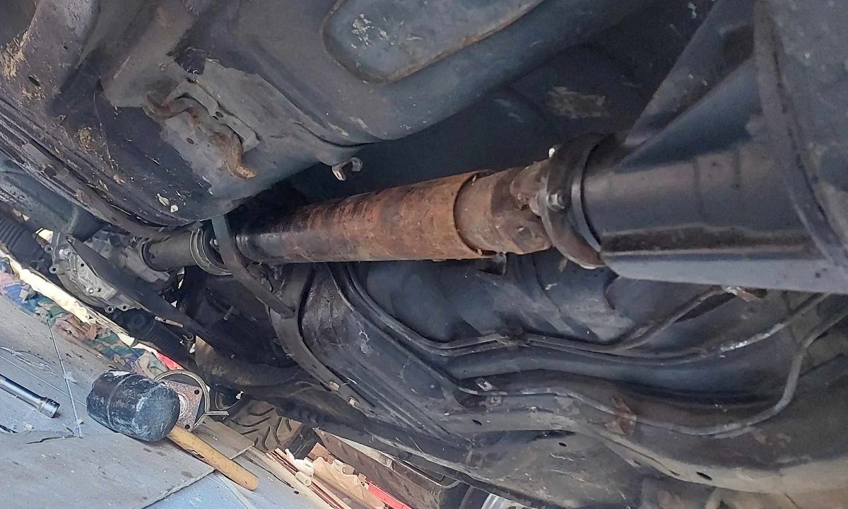
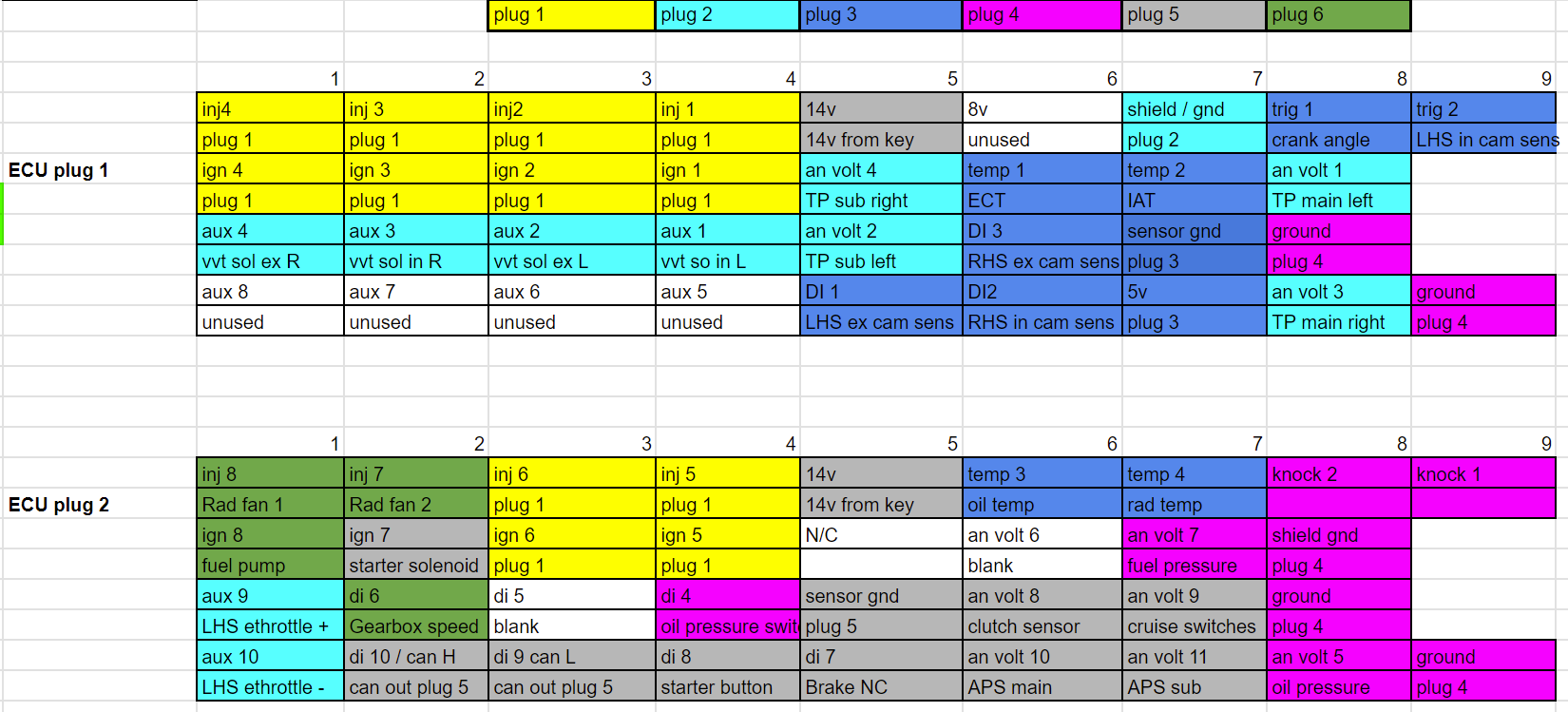
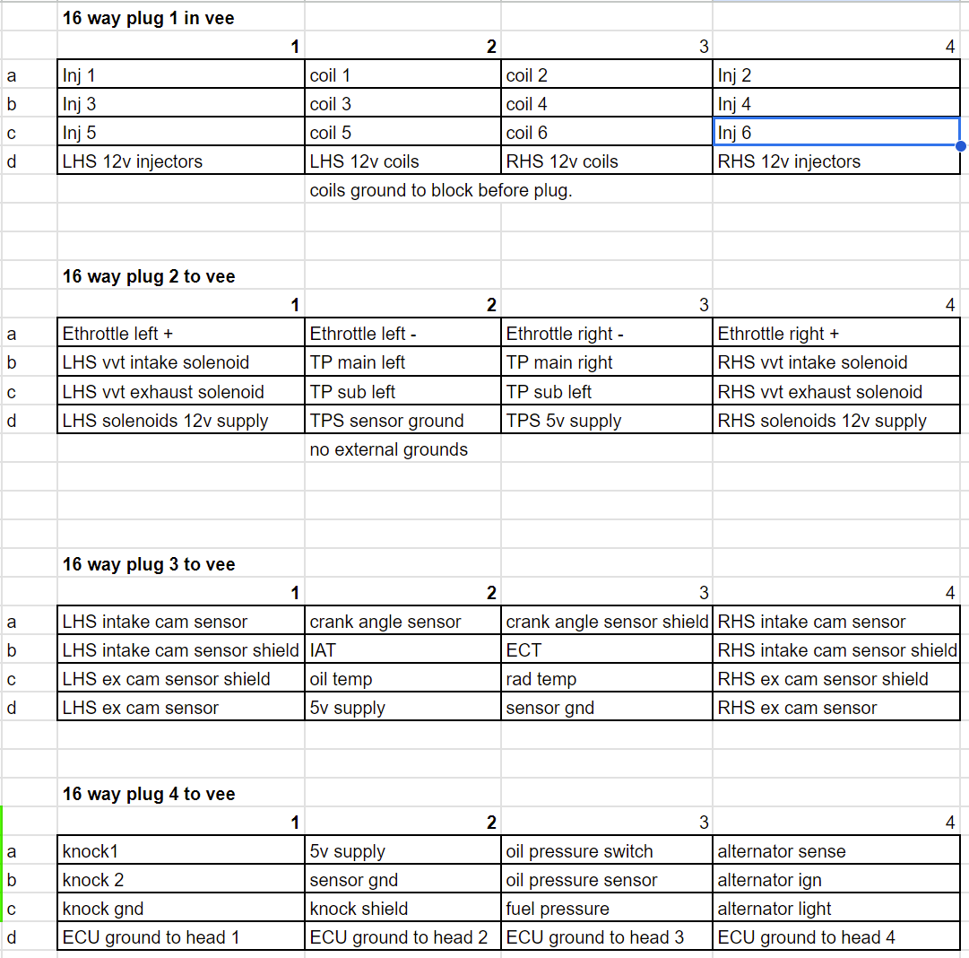
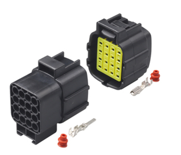
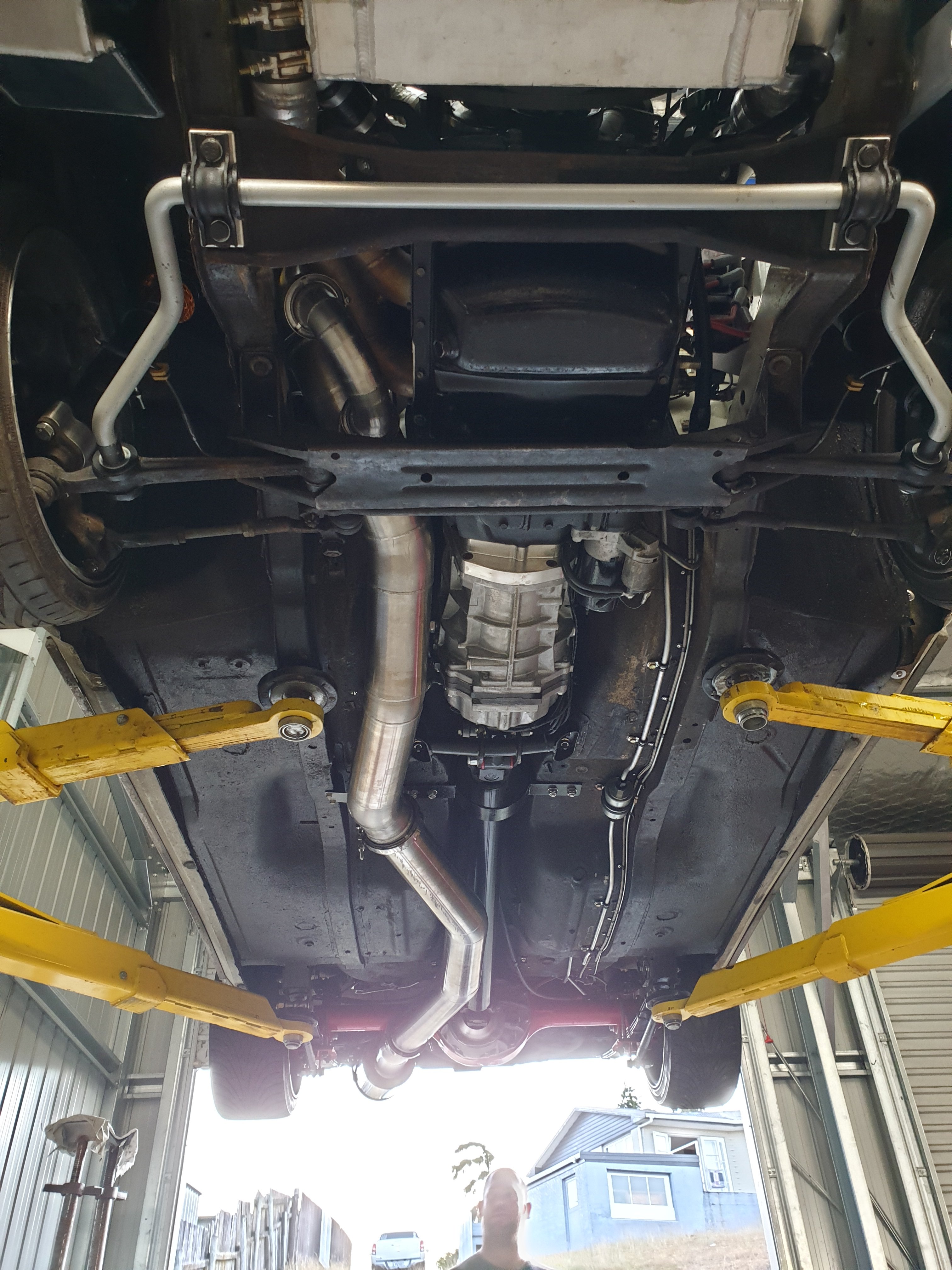
I managed to get the radiator sitting a little lower, so I actually think it will be okay even when engine sits down a bit more. I had a mix and match of various driveshaft pieces, and have managed to put something together that is the right length. Sweet! The UJs seem okay but I should probably get them rebuilt so I dont have another incident. breaking the front UJ at ~80kph was scary. I've started on the loom. I'm gonna have 4x 16 way connectors that live in the vee of the engine, like this: then 2x 12 way plugs on the cabin side that connect the ECU to other stuff. What I found on the last loom that I made for the echo. Was that although I tried to make things tidy, the plugs into the ECU were messy because things unnecessarily crossed over a lot. So for starters, just trying to allocate everything to the 4x plugs. In a way that makes sense for position in engine bay. And keep the higher voltage stuff away against shielded signal wires or whatever. Then I've just allocated everything fairly randomly to relevant pins on the ECU and see how it lays out. Then reorder things so everything is grouped together as much as possible, so the plugs dont become a god forsaken mess like every other time. This has paid dividends as it made it easy to see that if I just swap around input 1 for input 5 (or whatever) then the grouping improves considerably. Also, it's made it way way way easier to actually make the loom - Firstly because it's broken down into 4x sub looms and each of these are smaller, less intimidating tasks. Then secondly the main branch of the ECU into the engine bay is just a straight run ending in 4x plugs. Rather than branching out to everything. So it's way easier to test and trace the individual sections. I've already finished the first sub loom, for injectors and coilpacks. Fairly quickly because it's so much easier when you're working to a plan. Maybe this is why wiring diagrams exist? Who can say? Injector wiring looks fairly discrete which is good. The coilpack wiring is a bit more obvious, (waiting on some more terminals to finish it) but should hopefully still look nice and tidy. These days I prefer to just stay with more thinner branches rather than trying to incorporate everything into one. Partially because I always end up chopping and changing my looms around. But also 4x smaller branches end up considerably more flexible and easy to position. As I'm not using tefzel wire that easily slides against itself to make super flexible motorsport spec looms. (TXL is a cheaper automotive spec alternative) Hopefully I'll get most of this smashed out fairly quick once some extra terminals turn up.
 13 points
 -
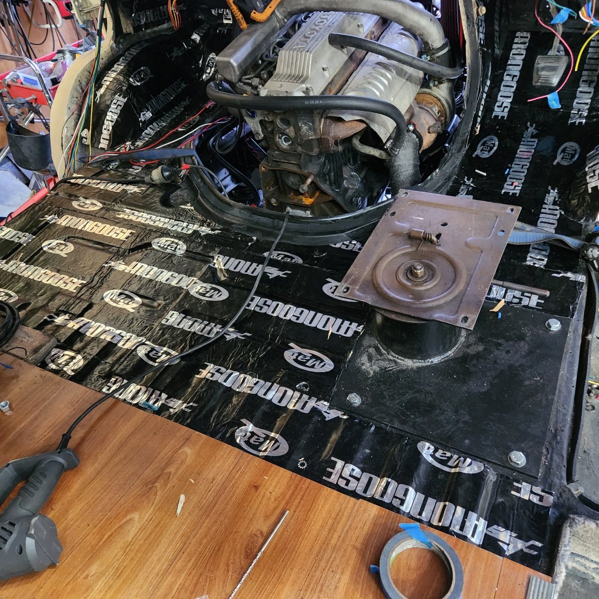
I bought another container to improve my storage situation, this meant I could move the X to the new one to give me a bit of room to move around it. Things were a bit tight on the other one with that shelving. I took the opportunity to take a few pics and analyse the state of play; Mmm crusty. There is evidence some welding has taken place but I'll strip that POR15 off to see what shenanigans are going on. All tucked up again11 points
-
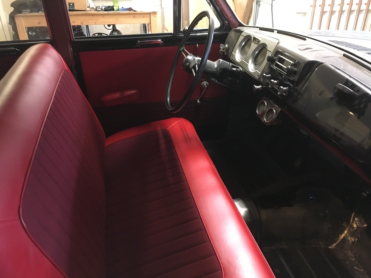
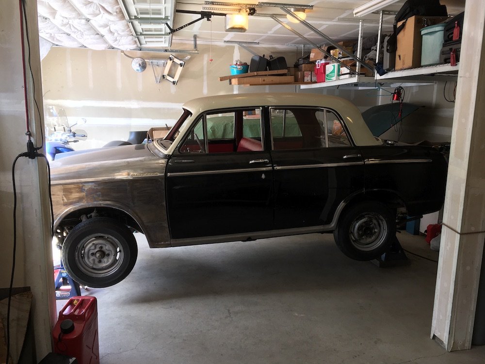
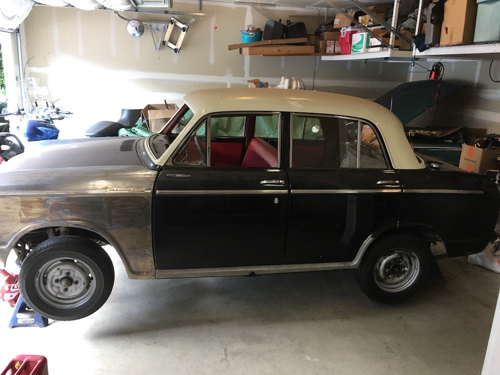
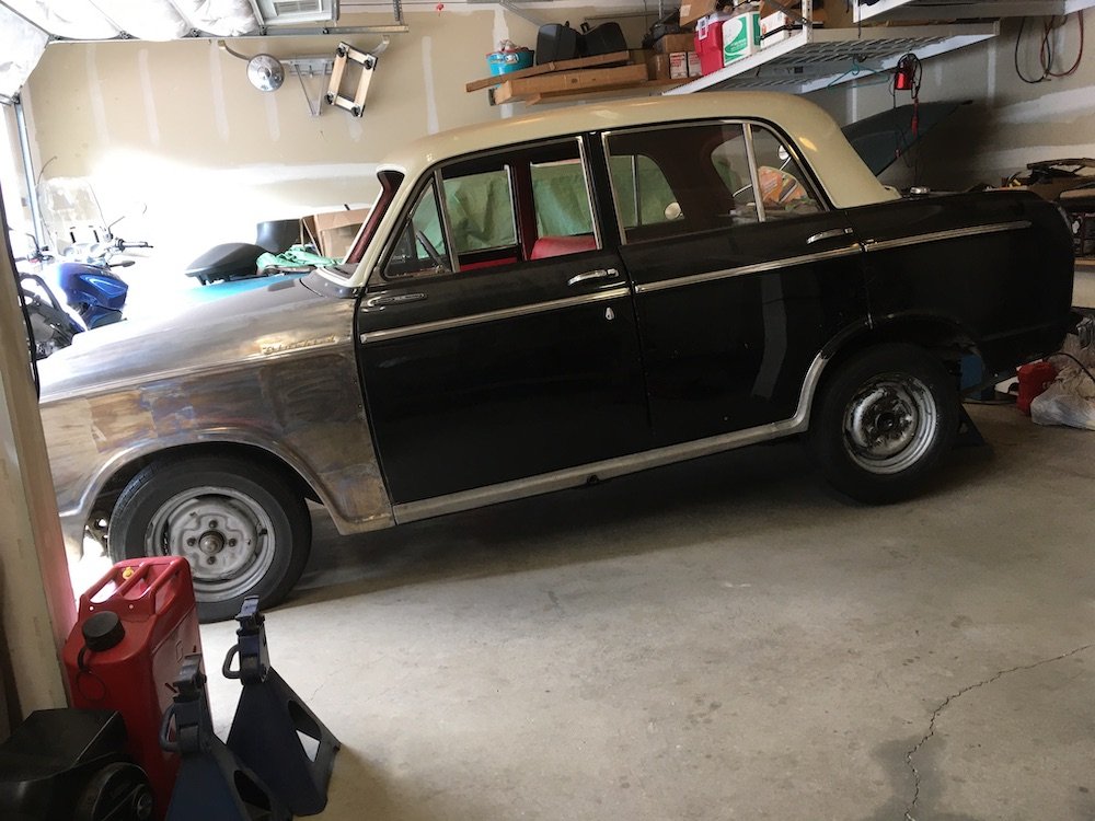
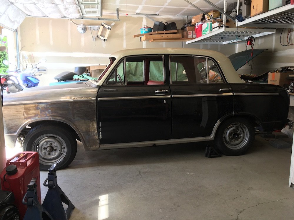
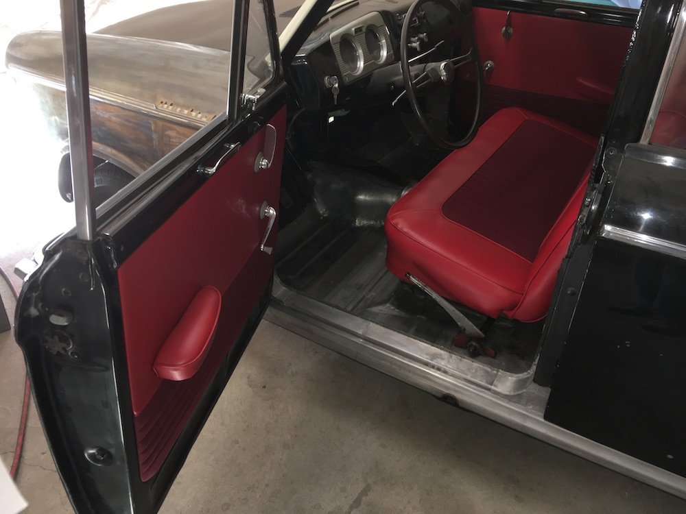
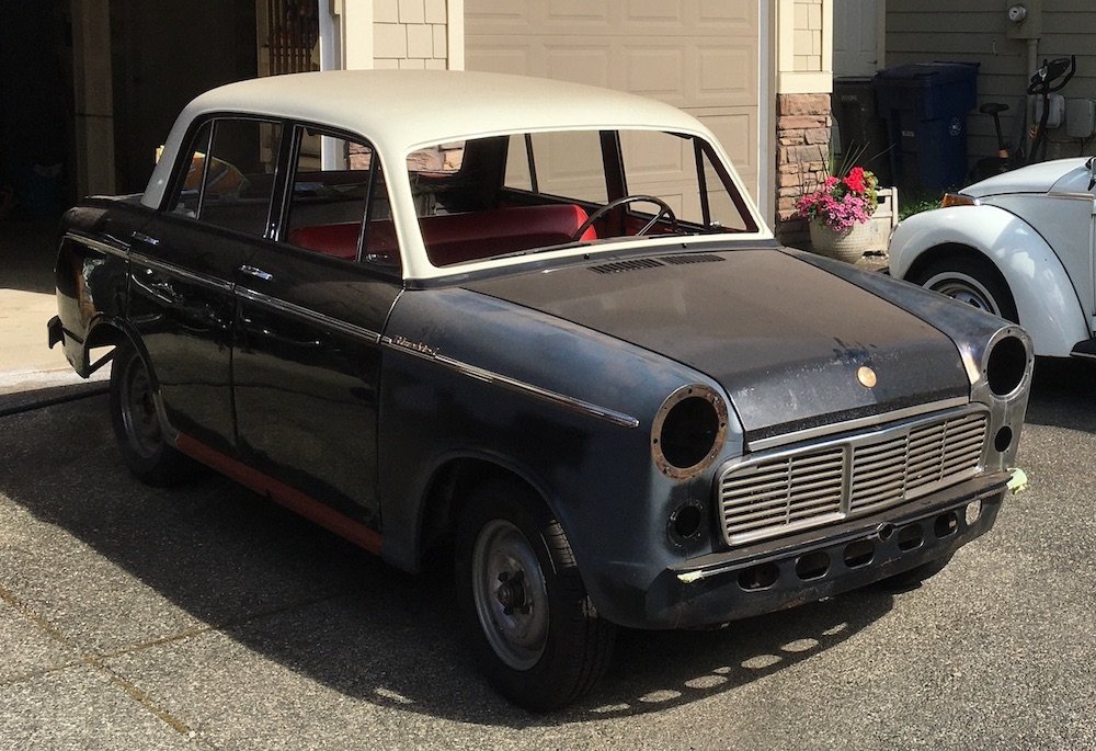
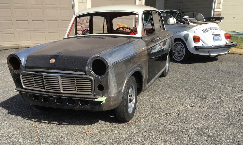
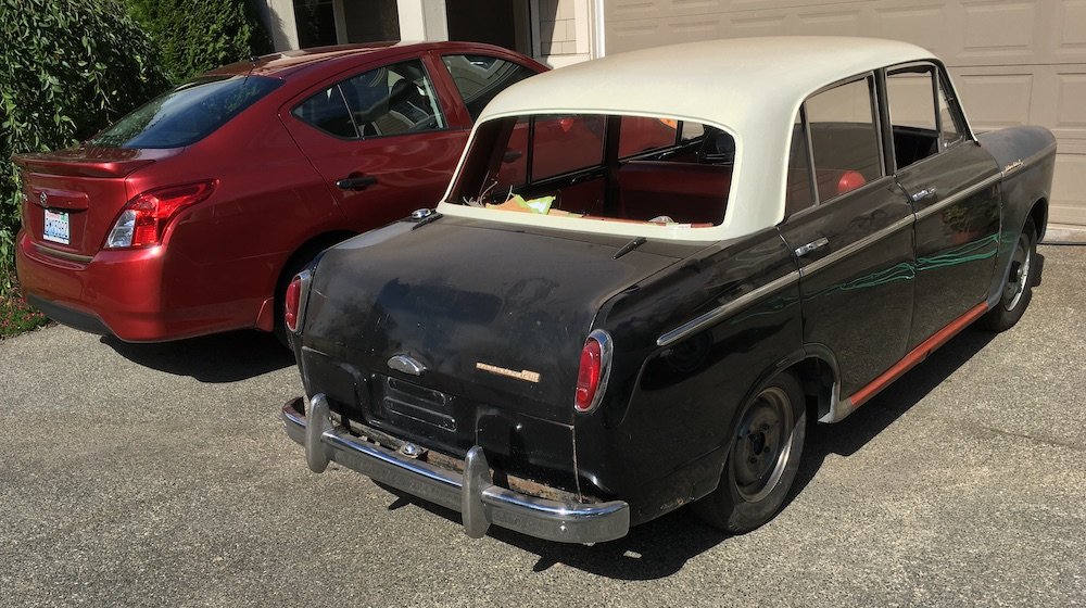
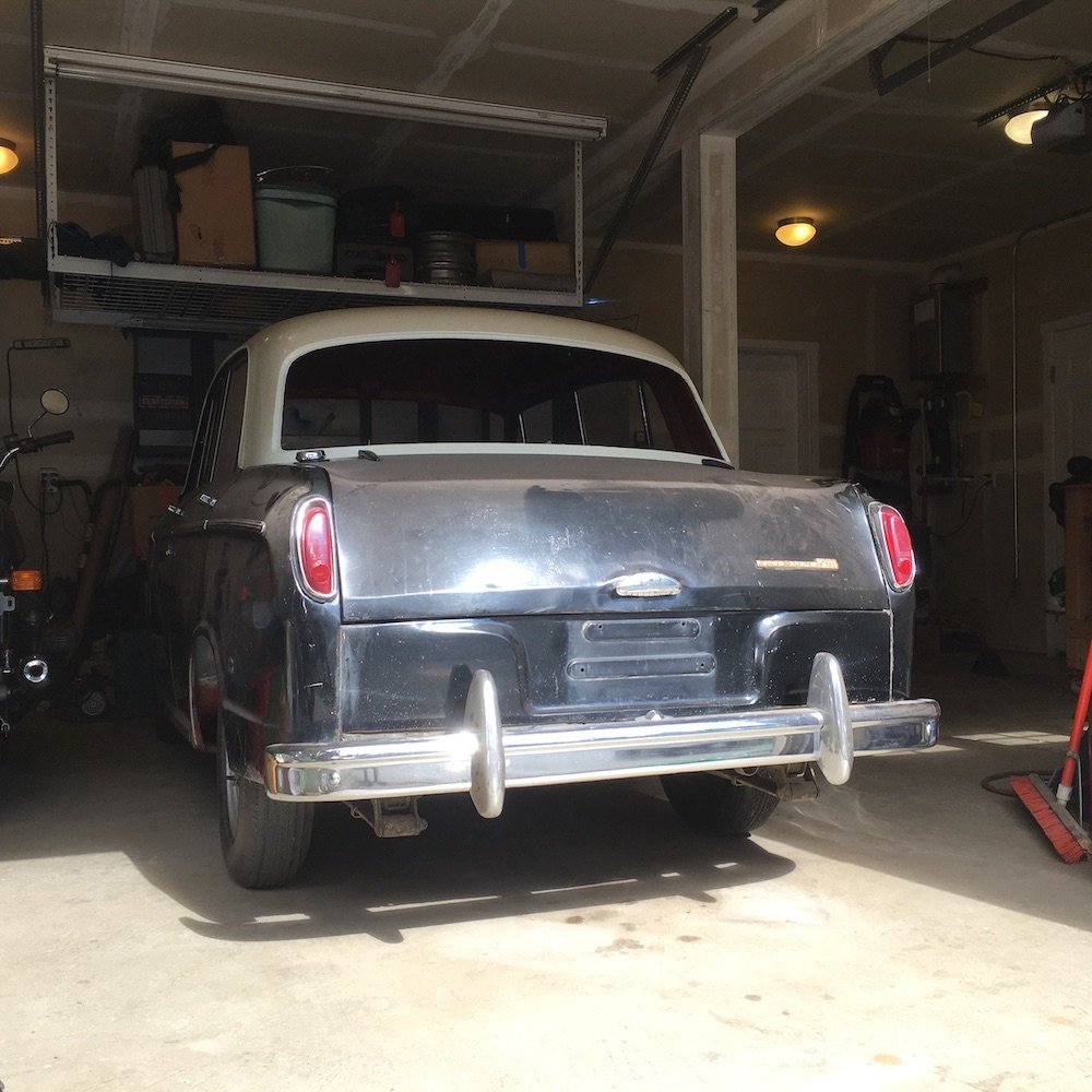
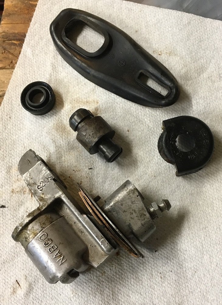
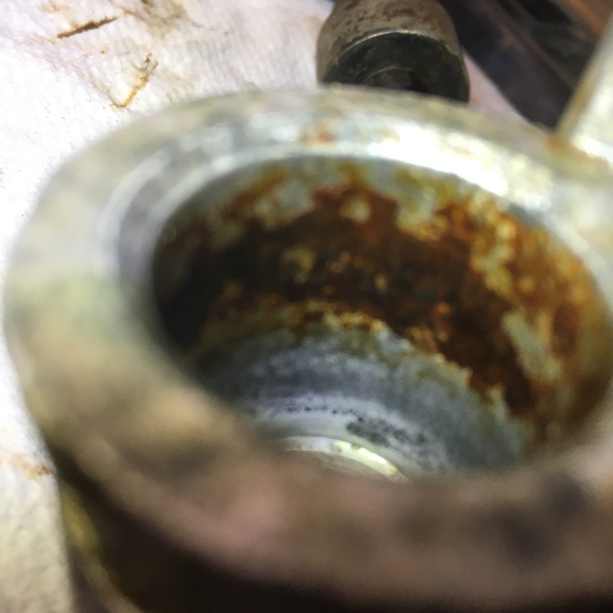
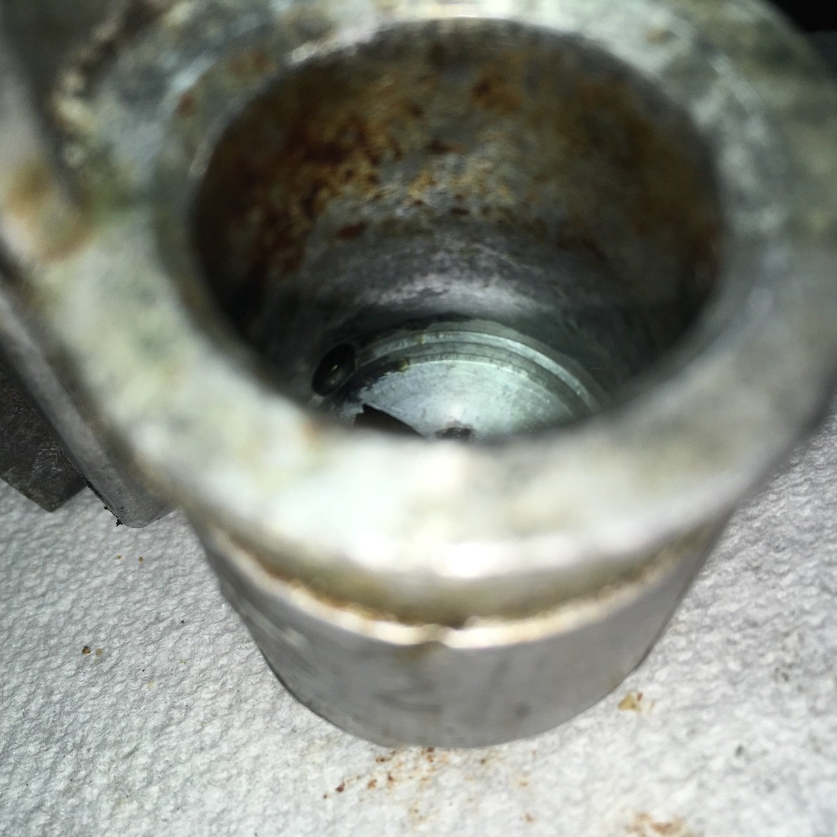
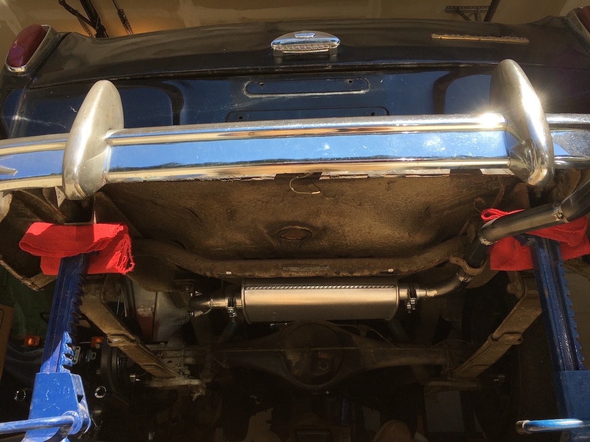
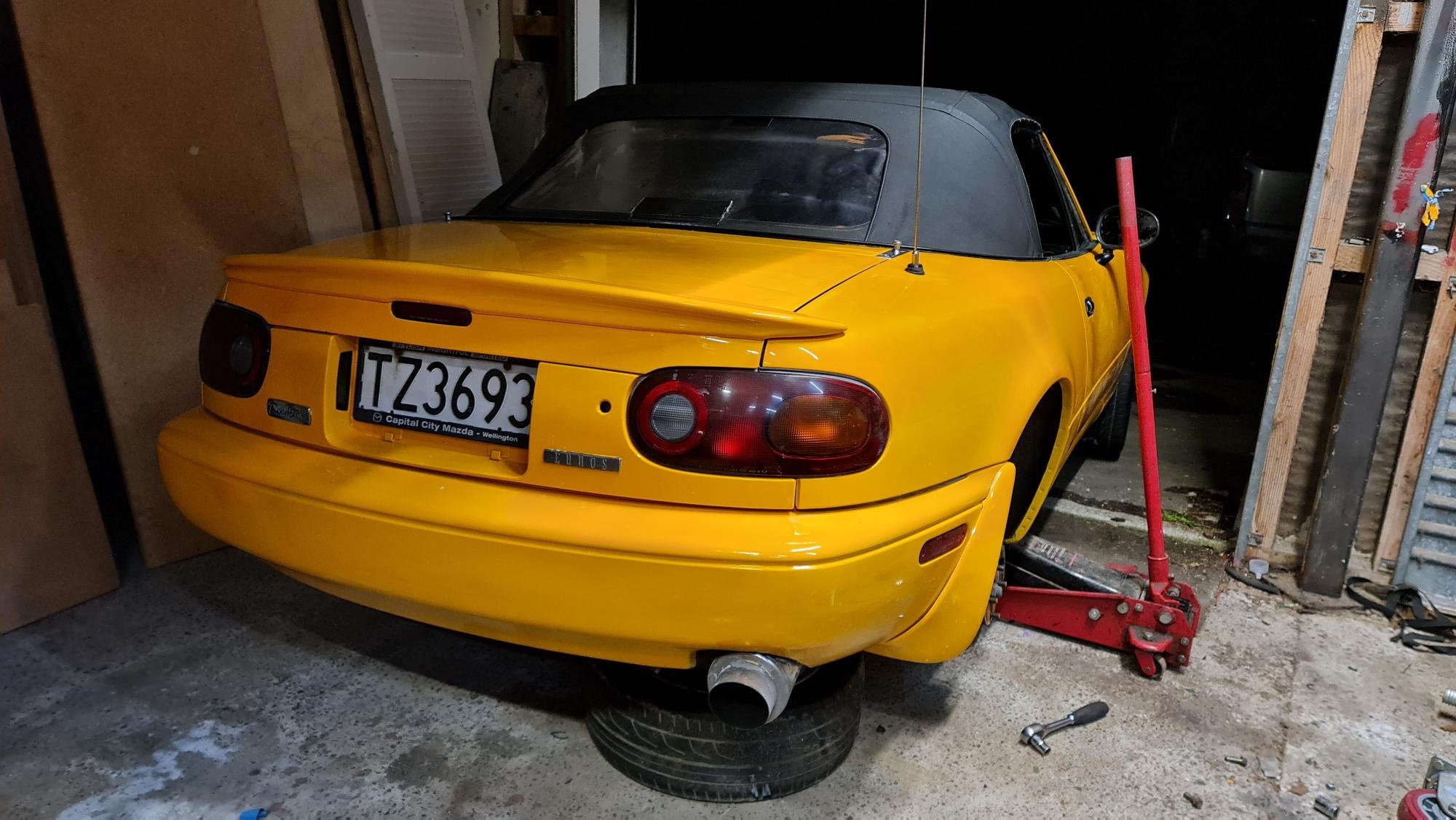
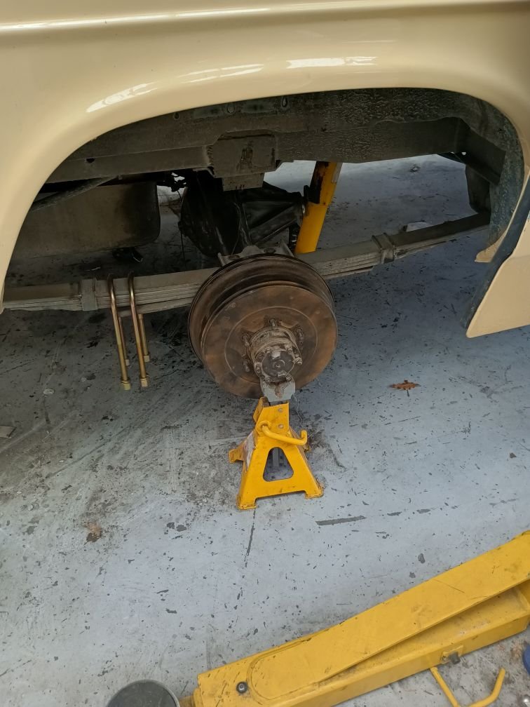
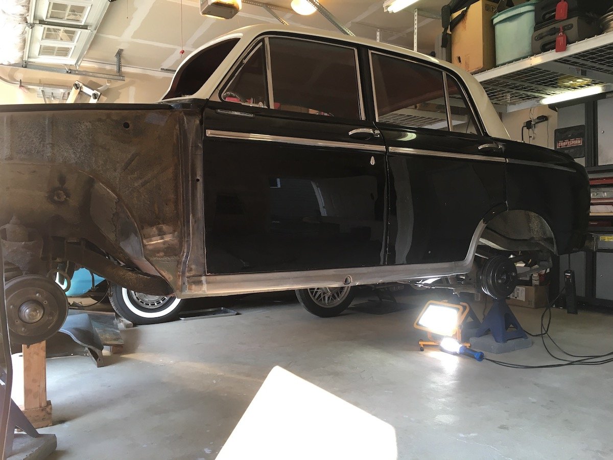
Building the 1961 Datsun 310 Bluebird - Drive Time - It Moves! Lowered the Bluebird and drove it around only in front of the house for a few photos and repositioning back into the garage. First time back on its wheels in six years! Btw, I could use a couple more OG wheels (4J by 13 with stick out mounting clips for the hubcaps) as one is very bent and another is badly rust pitted. Still looking locally but so far no luck finding any in serviceable condition. A couple of issues happened but were expected. One, it was very loud without any exhaust pipes/muffler. My neighbors did take note of the emergence of the Bluebird, especially after giving it a few healthy revs. Two, one of the hydraulic brake cylinders locked up in the full on mode. This was semi expected since it had been a while since I'd serviced the cylinders, My experience has been that wheel cylinders tend to build up rust every few years of inactivity on the dry side of the piston cup seal. And this happens regardless of how clean I keep the brake fluid free of moisture contamination. Getting ready to launch. Temporarily bolted in the front seat. Only took a couple of minutes by threading on four nuts to the mounting studs. Lowering. Rolled out the floor jack and began an iterative front to back lowering of the Bluebird off the fully raised six ton jack stands that had been raised even higher with concrete blocks underneath. The lowering sequence begins... Time to hop in! The mighty loud 1.2L engine starts up just fine and the Bluebird finally drives out of the garage and into the warm summer sunshine And then, after maneuvering the Bluebird back and forth a few times in front of my neighbors houses, the brake lock occurs. This was temporarily remedied just to get it back into the garage by tapping the back of the stuck right rear wheel cylinder a few times with a brass drift. The bird heads back into the roost. One of the rusty brake cylinders. Easily cleaned up the bore and piston with some 600 grit wet or dry paper. Followed with acid clean, etch and zinc phosphate treatment on the steel piston. Repeated process on the other three wheel cylinders. The aluminum cylinders will not be honed since the soft bore ID would become too large and not make a good seal. Brakes now function and seal fine. So the next thing I addressed was the exhaust system. In the next post I'll cover the build of a simple home built design from straight 1 1/2 inch pipe plus a kit of pre-bent header piping bits cut and MIG welded to an economy muffler. First time making an exhaust system from scratch for me and it was another learning experience.
6 points
-
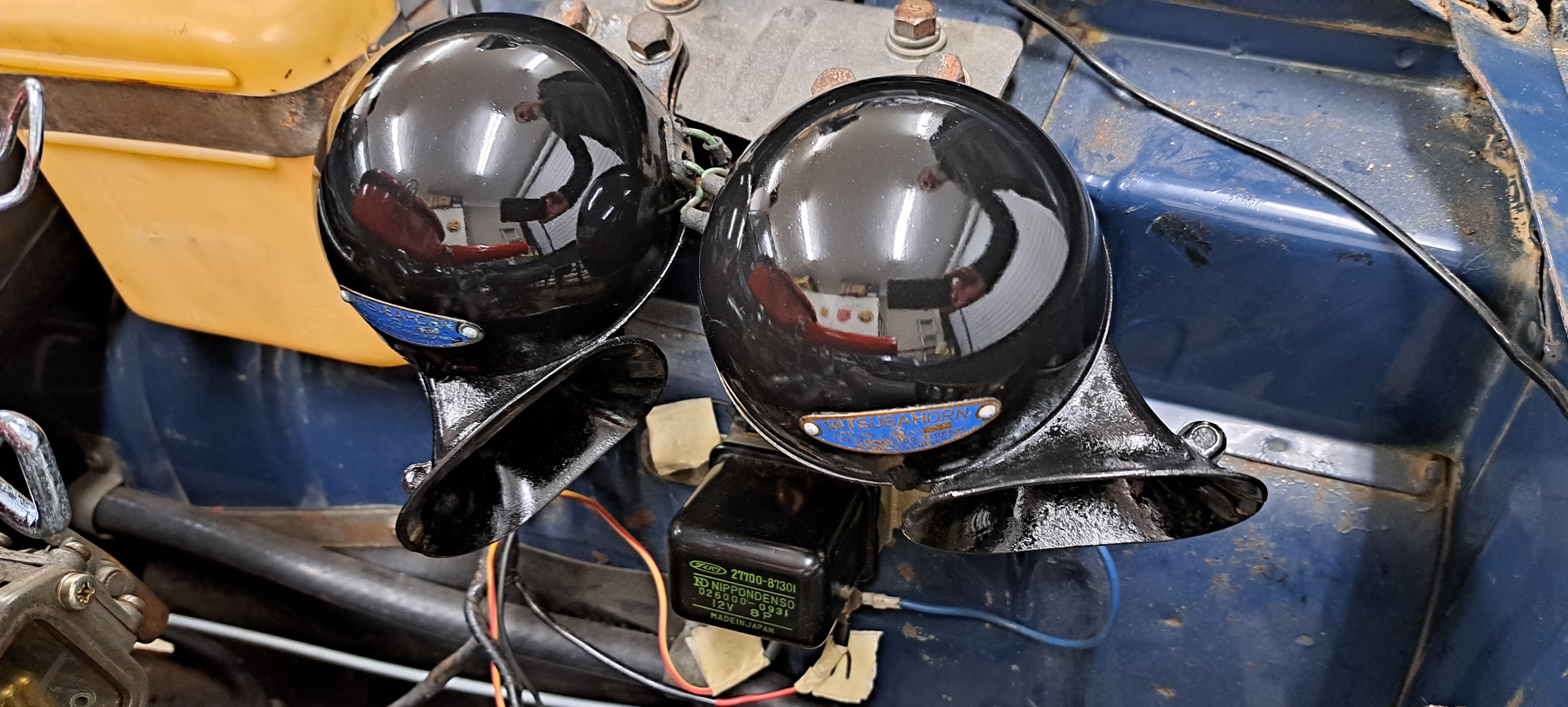
Like just about every other part on this car .. the water pump seal is made of unobtainium. So a small mod to the impeller and its now got a much more common seal. Oh and a picture of some fine hooters Freshly painted
4 points
-
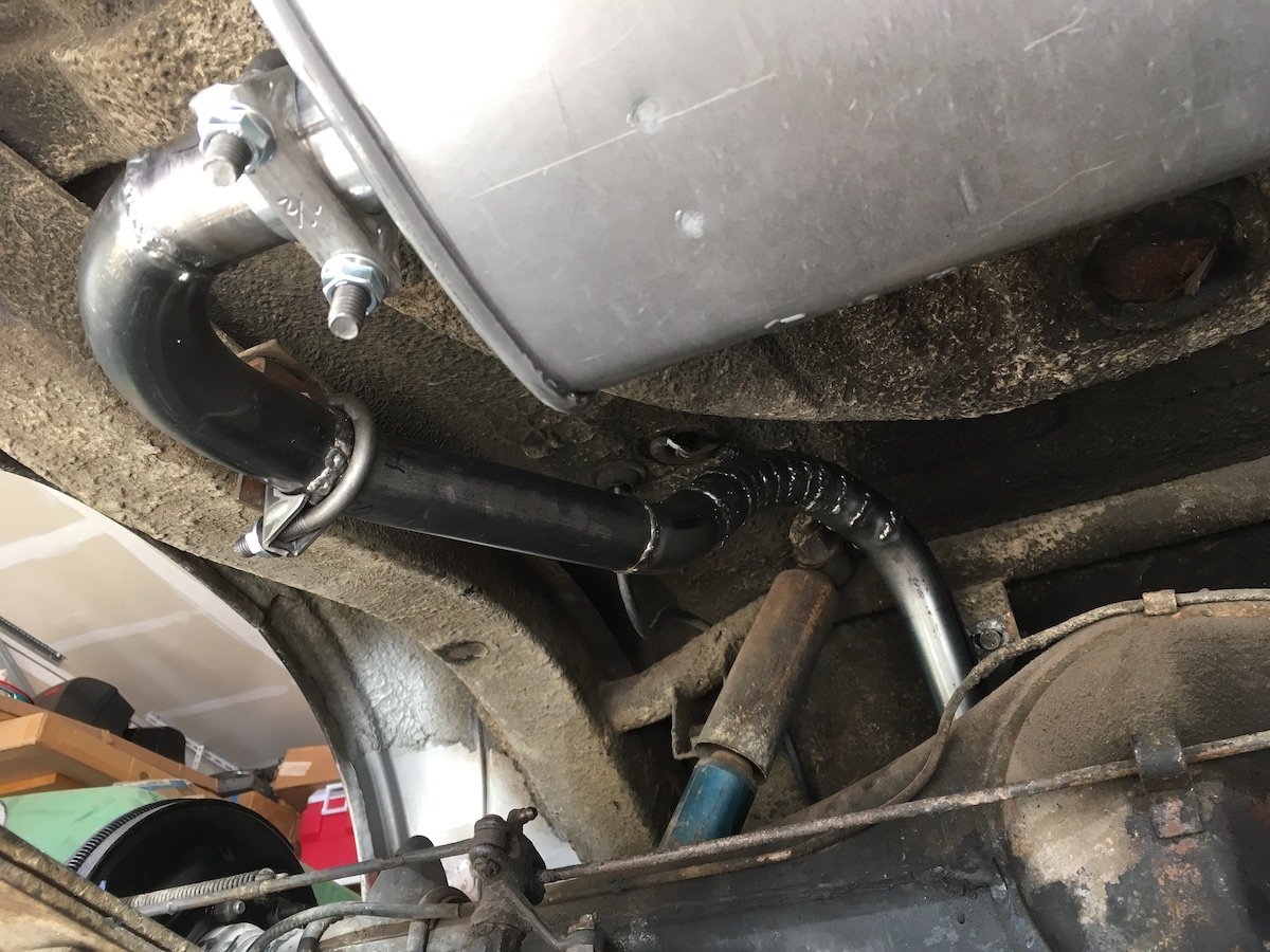
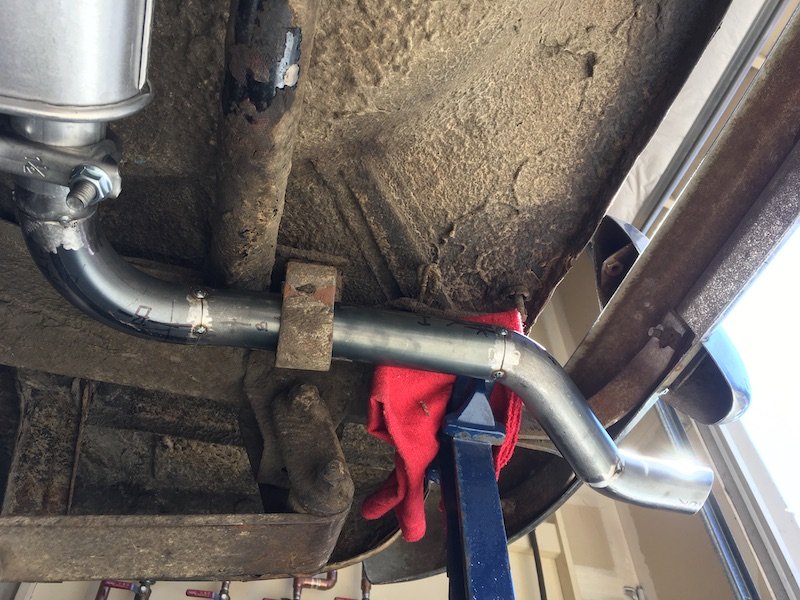
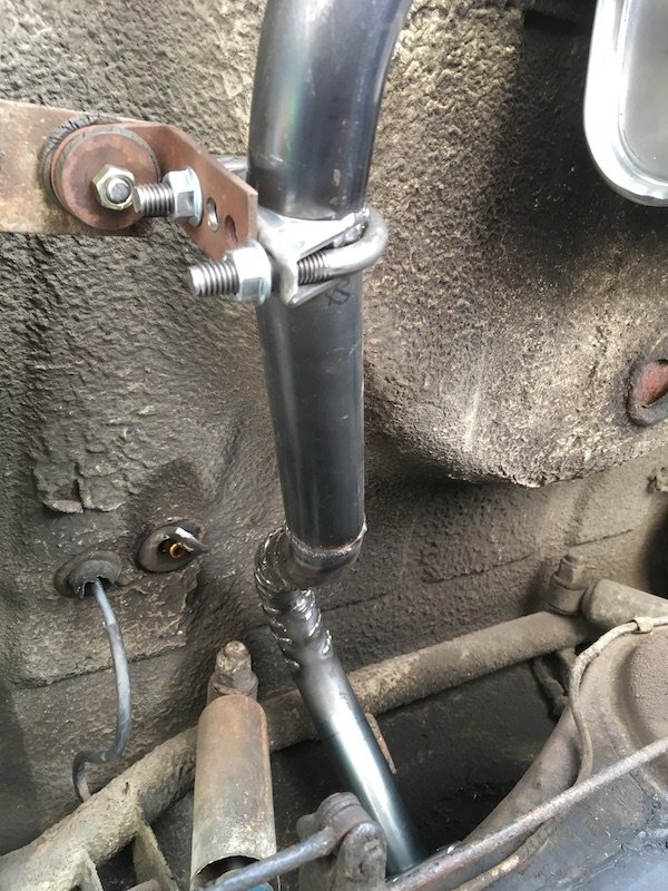
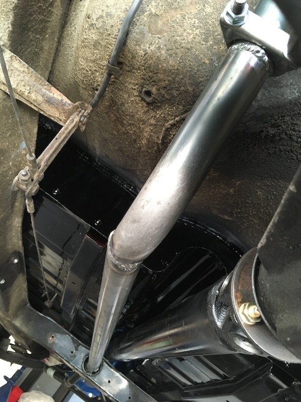
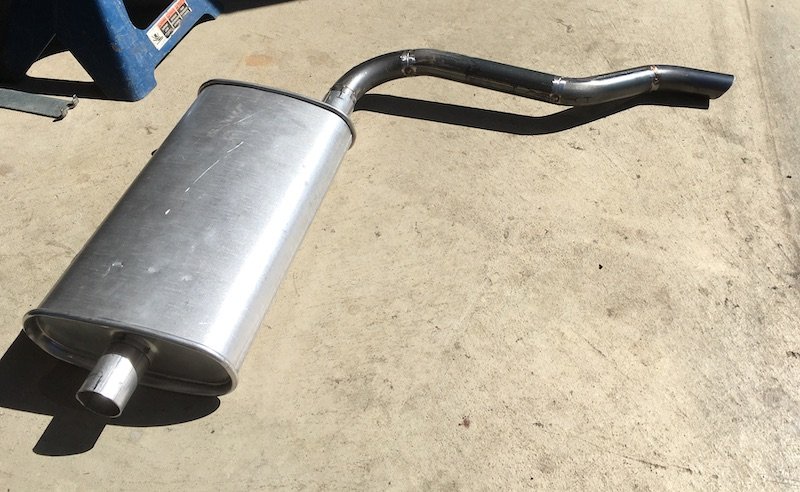
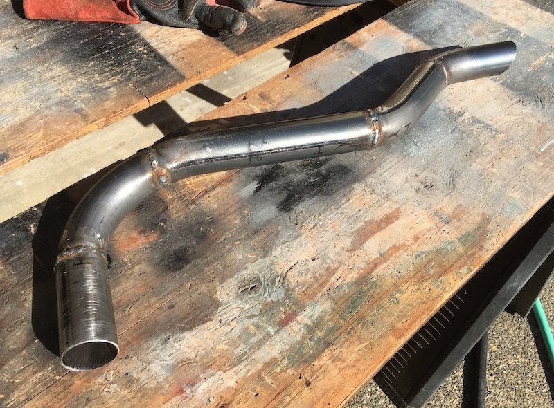
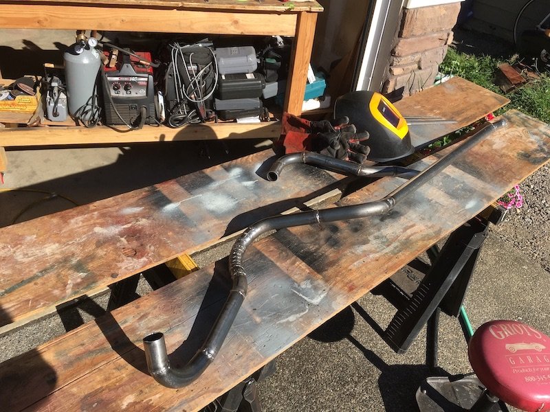
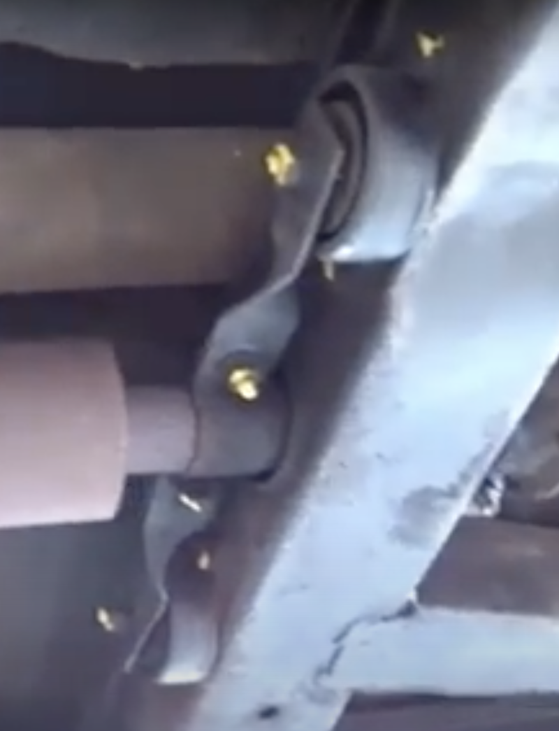
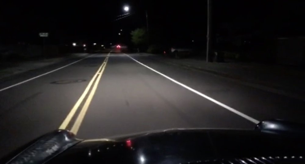
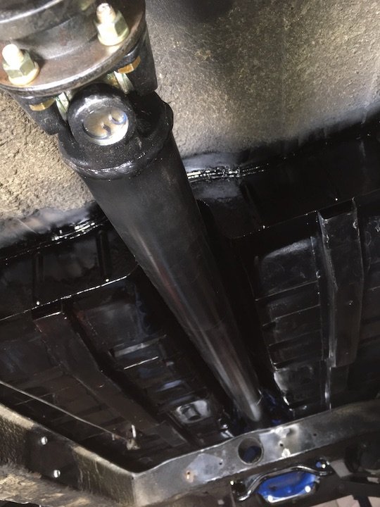
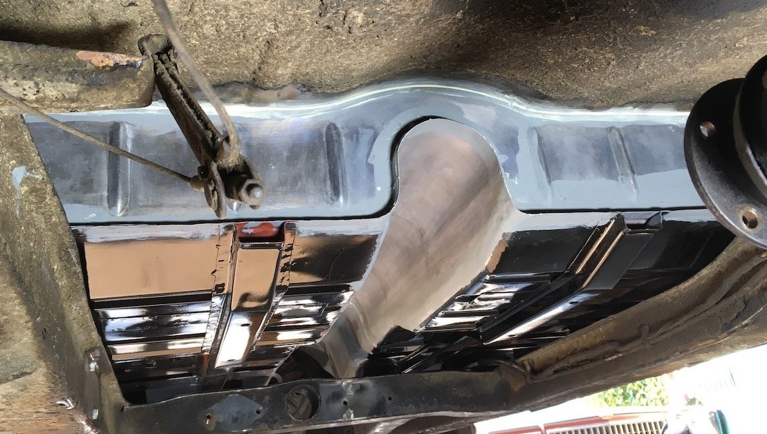
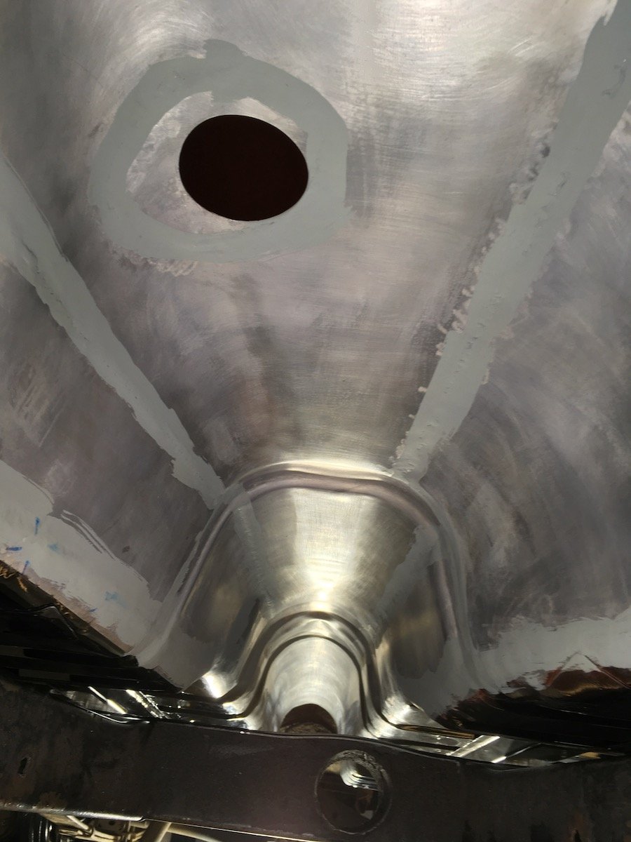
Building the 1961 Datsun 310 Bluebird - Exhaust Pipe and Muffler. Making exhaust pipes and muffler installation. I've never done this fabrication work before but there is no other economical alternative. There does not exist a made to order system that I can just bolt up and hauling costs for transporting the car back and forth to a shop would be close to $350 plus maybe another $500 to $700 labor costs for a true custom quality professional quality job as opposed to a quick in and out one hour job. So I went forward to make my own exhaust system. Nothing fancy in materials, carbon steel, or design, two pipes connected to one $25 muffler from O"Reilly auto parts. The drop or header pipe from the engine is a very old stock aftermarket piece about three feet long that I was lucky to find on eBay many years ago. The small muffler is being test fitted and adjusted at what should be close to the original stock location. Adjoining pipes are only tack welded together at this time. There was a lot of back and forth fitting and adjusting while laying on the floor. Wish I had a fancy lift to save my back. Anyway, it doesn't look too bad in this view but hiding in the shadows is the crude routing above the rear axle housing. Going a bit further forward..., Ugly happens. I regret making way too many pie cuts and welds to get the curvature over the axle housing. Maybe next time I'll use just a few curved pieces with short straight lengths in between. Backing up to the tail pipe, I had become more proficient by this end point and chopped and fitted the elbow and straight bits more to my liking, dodging nearby body, frame and bumper structure, and with a nice angle cut across the outlet. Btw, shown is the only factory original clamping left, all others are left over from long ago quick cheap jobs done by muffler shops. One clamp was definitely not safe. A shop had drilled a hole under the rear seat cushion straight through the body sheet pan and hung a support and clamp without any sealing added to prevent exhaust gasses from getting inside and causing CO poisoning. I have welded that hole shut. Same tail section fabrication off car. And then the long straight section looking forward to the pass through hole. The fit to the curved piece wasn't perfect but it works. There are the diamond traces of the original somewhat complicated support clamp assemblies at the forward frame x-member. It will be another mini project just to try and reproduce those clamps since they are not available anywhere. I just have some photos of what the OG clamps look like. I clamped instead horizontally with a couple of generic tire rubber strap types that I can't even photograph because they look so bad and result in some rattle contact at the through hole. The not shown pipe connection forward of the straight pipe, and on the other side of the x-member, is the old stock header pipe mentioned earlier. No problem with that pipe, it fit very good. A video screenshot copy of the OG clamping design at the x-member. Because of such a close clearance, good support is critical here to keep the pipe centered yet flexible as the engine and header pipe move about slightly on the rubber engine mounts under load and deceleration. The cylindrical section is backed up by a diamond shaped flat piece which bolts to the x-member. I'm guessing there is a rubber isolator inside the cylinder. These clamp assemblies are not available, at least not new, and I'll figure out a way to reproduce a pair eventually. Only guidance I have is this photo and the diamond imprint on my x-member. Workbench view of my finalized pipe creations. Ugly unground welds left as is for integrity and containment of exhaust. Functional. The header kit bits used for the elbows were made of slightly thicker steel compared to the straight pipe and thus much easier to weld without the risk of blowing holes through. So after installing the exhaust, I installed lights, blinkers, front bumper, number plate, then waited until about midnight and went for a stealthy and much quieter drive around the local roads to flesh out additional issues. The speed was kept under 35 mph because there is no front glass installed yet, thus also the stealth approach so as not to attract any unwanted attention. Only a few issues of significance showed up after about five miles of driving. One, the exhaust rattles badly at the x-member pass through. Two, the water pump bearings are worn out and making lots of noise. Three, there is just slight contact between the tunnel and transmission at one of the side cover plate uppermost bolt heads. All issues have since been addressed with appropriate corrections. Midnight test cruising in a Bluebird. More later on the "fixes."
4 points
-
Goes good.3 points
-
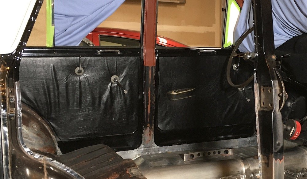
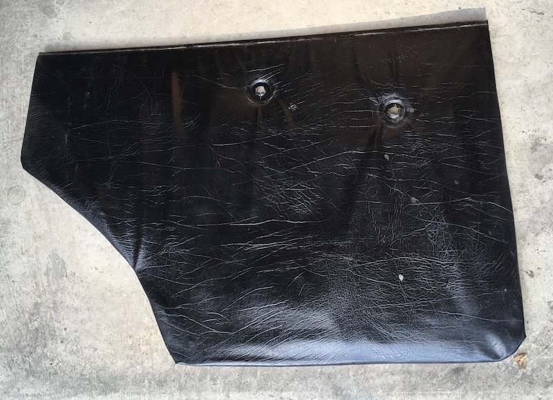
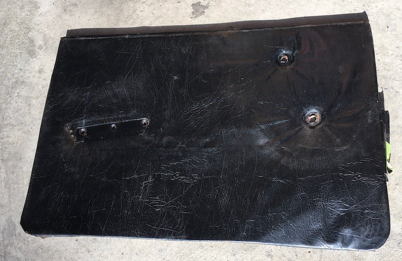
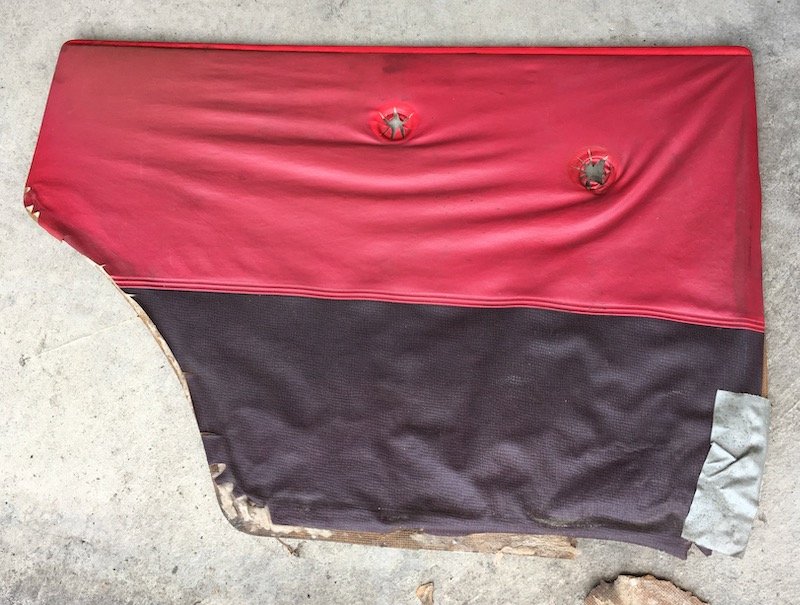
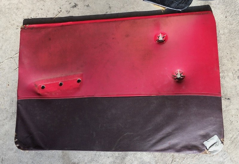
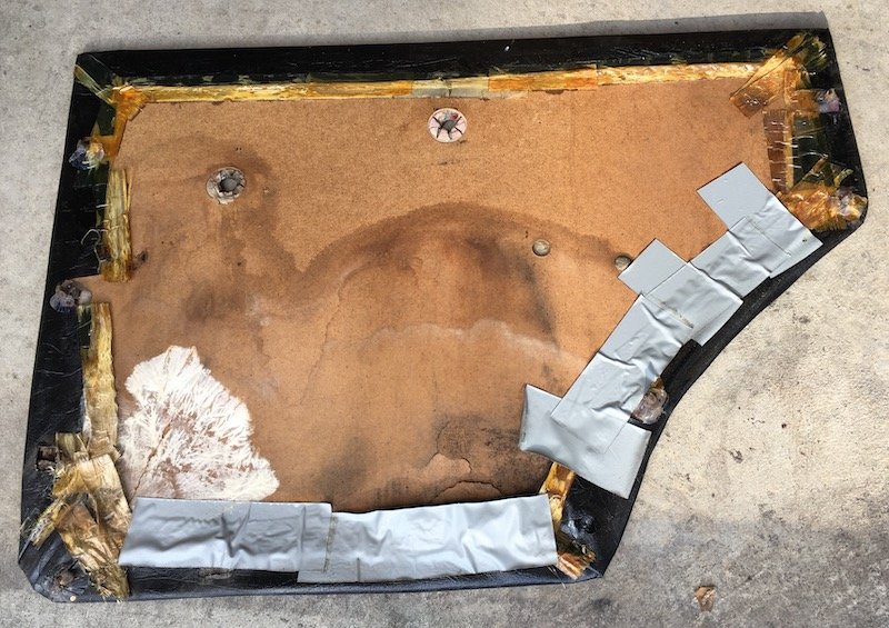
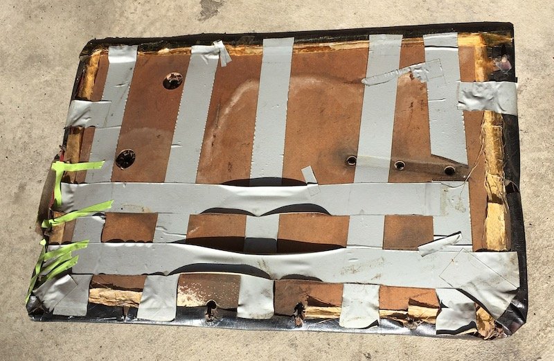
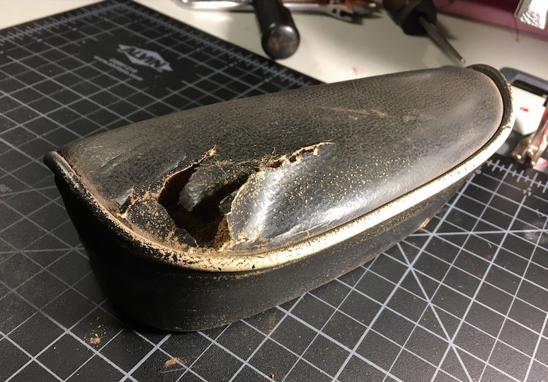
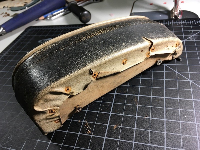
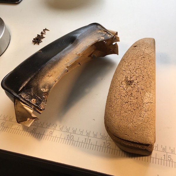
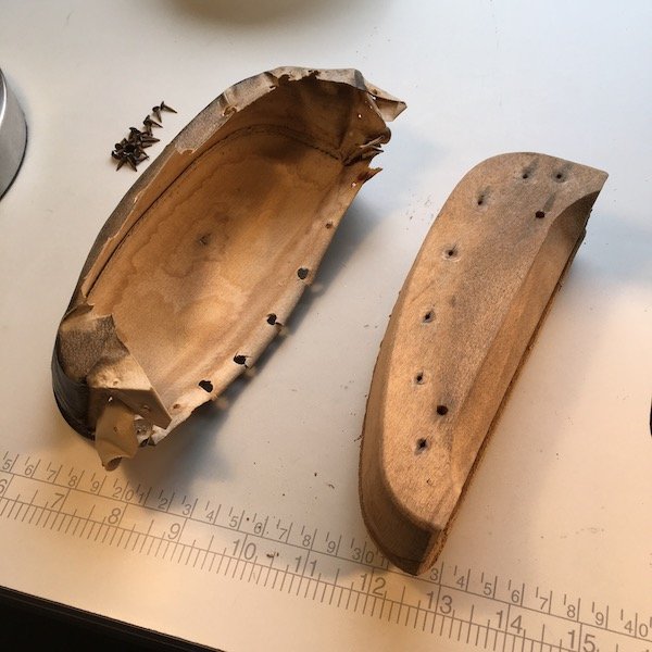
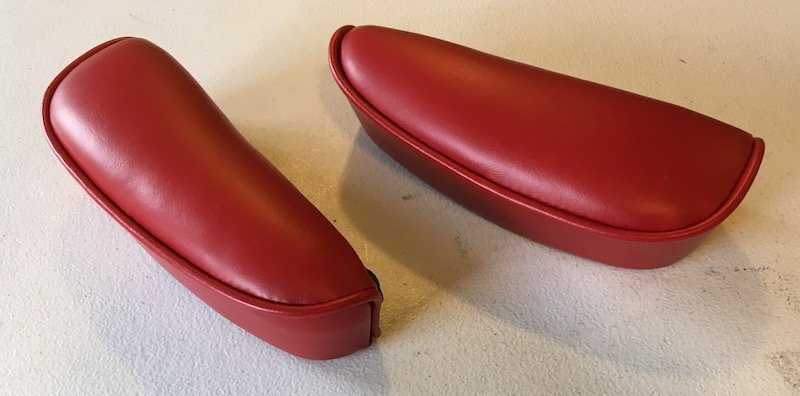
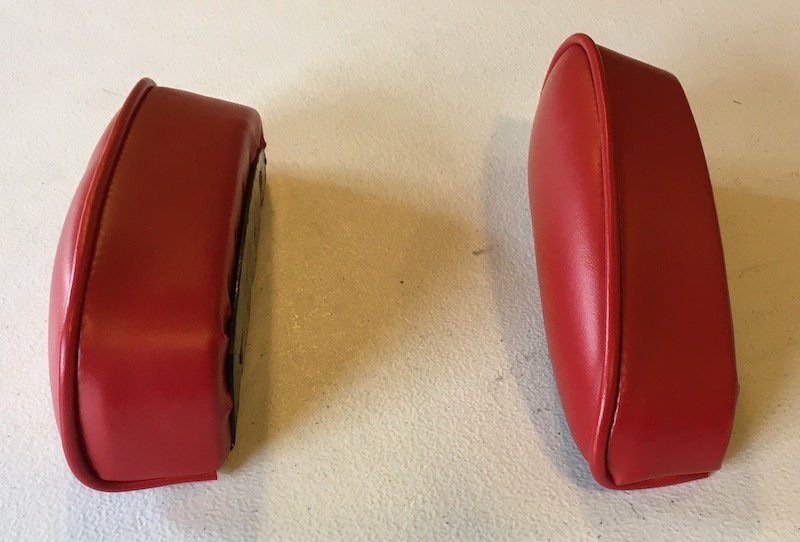
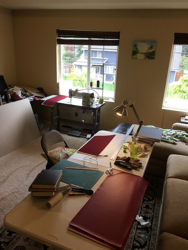
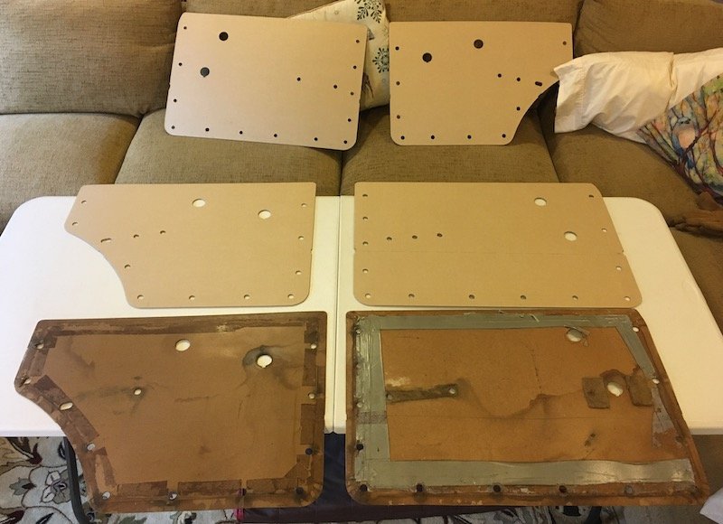
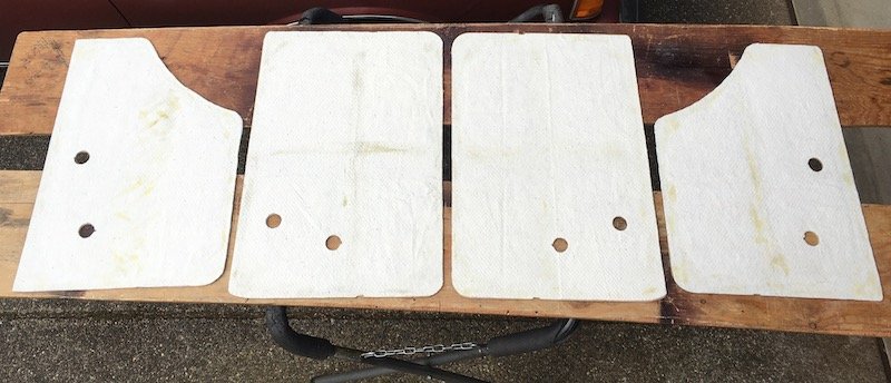
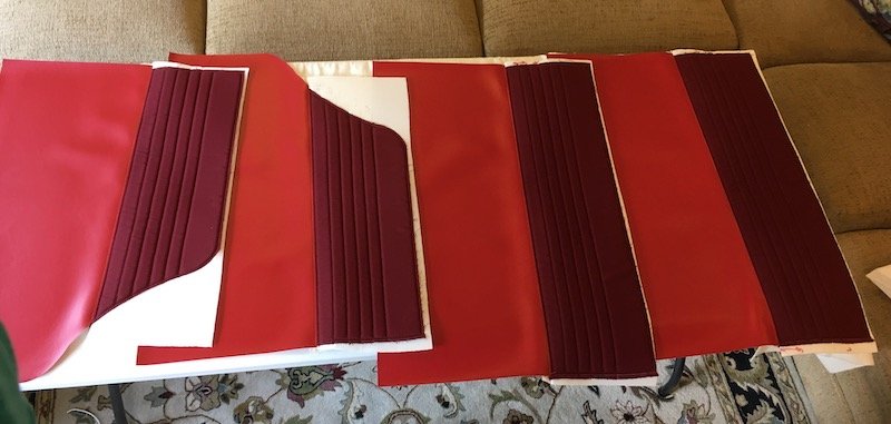
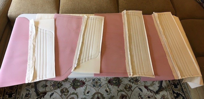
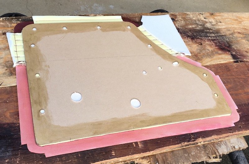
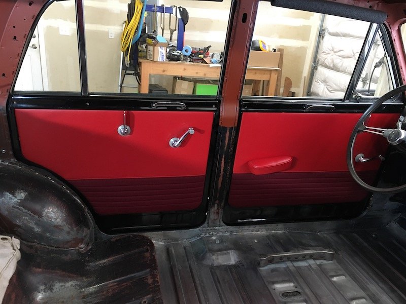
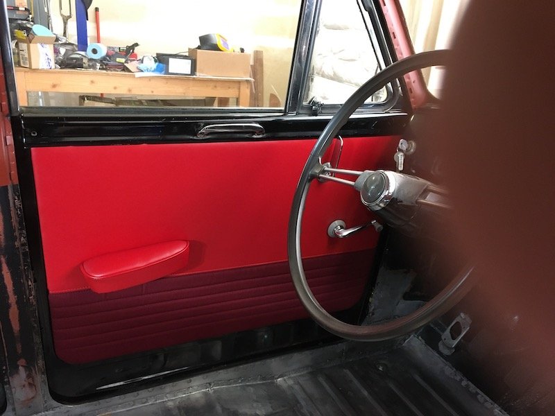
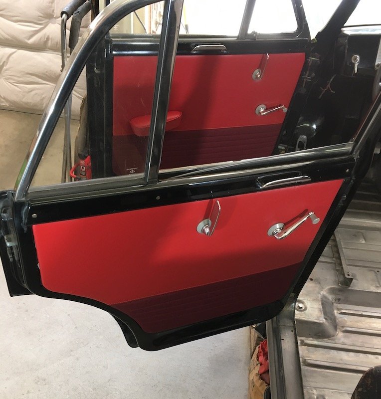
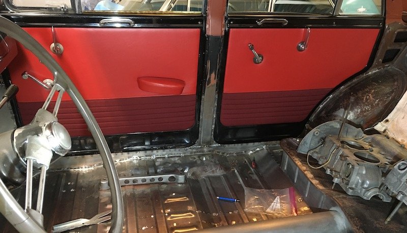
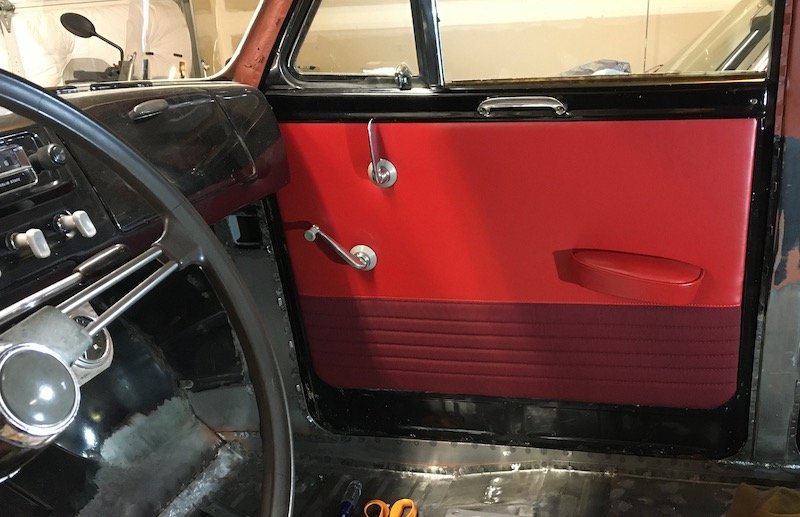
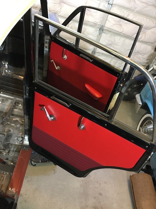
Building the 1961 Datsun 310 Bluebird - Upholstery Trimming - Door Cards and Armrests. Rebuilt the door cards, except maybe I should say made new ones minus a few salvaged clips and screws. Started with these black door cards which are not OEM covers, probably vintage 1971 or so. These didn't look too bad from far away but are. The old ivory armrests were salvaged from a parts car many years ago and painted black. Car was not equipped with rear armrests but there are mounting provisions in the door frame for them as optional parts. After removal photos. Then, lurking underneath are the factory original covers from 1961. Backsides showing water damage destruction and potato chip style warping. So I need new armrests to go with the new door cards I was about to make. Built some new ones out the old by disassembly and pattern making. Kept the original support base of solid wood and sponge rubber by filling some of the cavities with bits of glued in foam then glued a thin layer of poly foam on top of the repaired rubber. Covered them up with new vinyl and it's done. An easy sub job. Onward with the door cards then. Datsun Bluebird door card production central. I bought four new large door card sheets from Automotive Interiors and Accessories, INC, located in Belchertown, MA. These cards measured 32 by 48 inch each. I only needed two but four was the minimum order. Then I traced the best of the old cards onto the new and cut them out. All the holes were punched out with a gasket maker hole punch tool. Added some cotton batting as was found on the original construction. Weldwood contact cement was the glue of choice but have to use it outside because the fumes are really bad. Sewed up some cover designs similar to the original style except replaced the OEM vinyl lower half with pleated cloth on 1/8 inch foam to mimic the new seat style. Then glued all the new covers onto the new cards. Made a mistake here in that I should have trimmed out the spaces for the door clips and also should have trimmed back the 1/8 inch foam on the bottom edges. Messing with the aftermath of the mistake took several additional hours to trim once the material was glued. Finished products in trial fit installation. No problems and looks acceptable for fit. The light gray bezels should be dark gray for this model year as shown on the rear door above. All the light gray bezels shown (and plastic dash controls for choke, wiper and lights) are salvaged from a later model Bluebird PL311. Not too noticeable though. So I guess it looks kind of plush for a homemade trimming job but not too much.
2 points
-
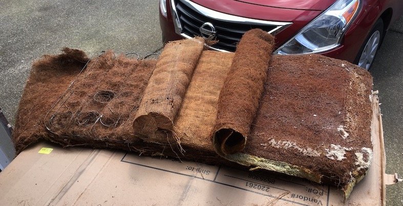
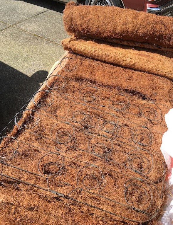
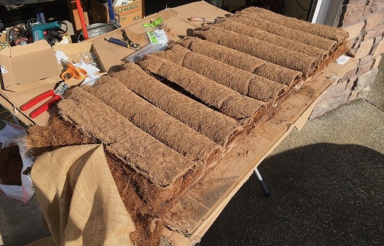
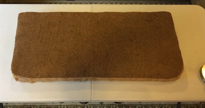
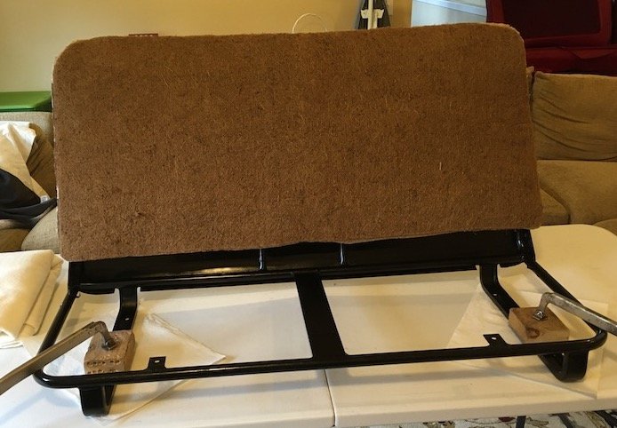
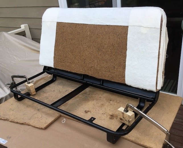
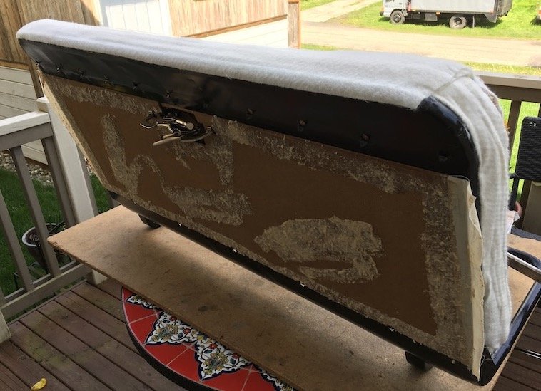
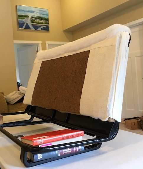
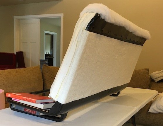
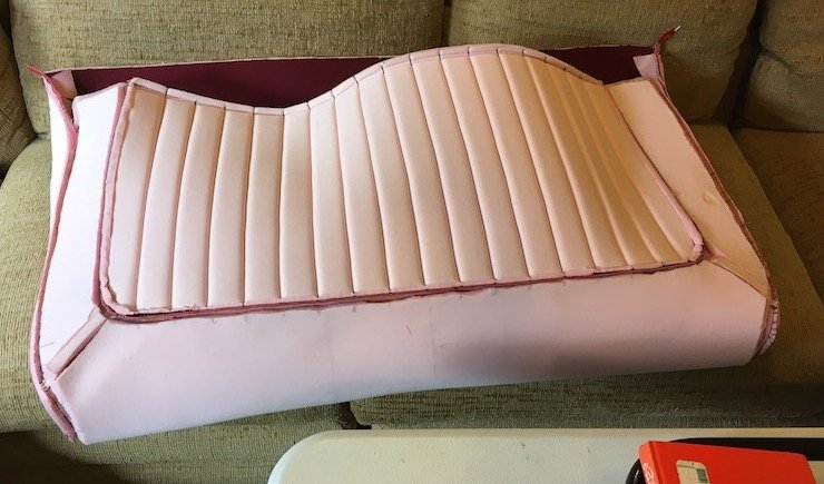
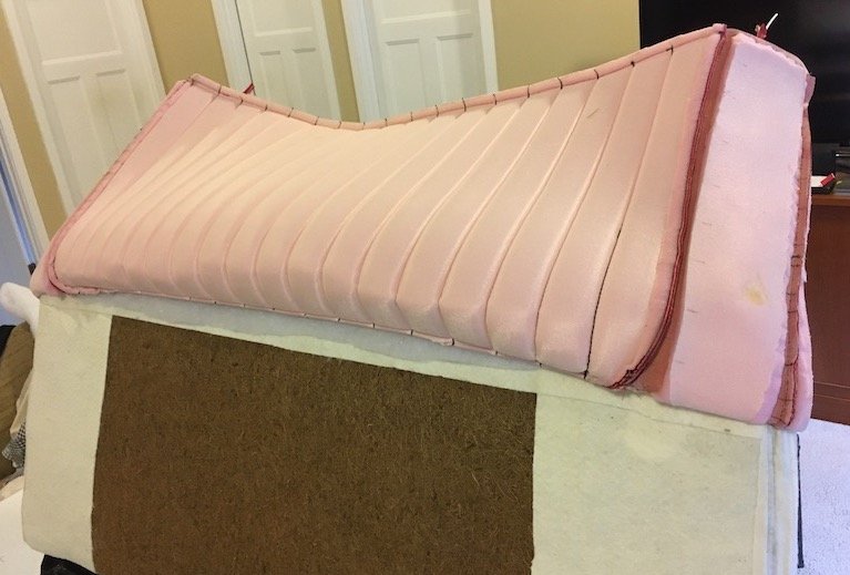
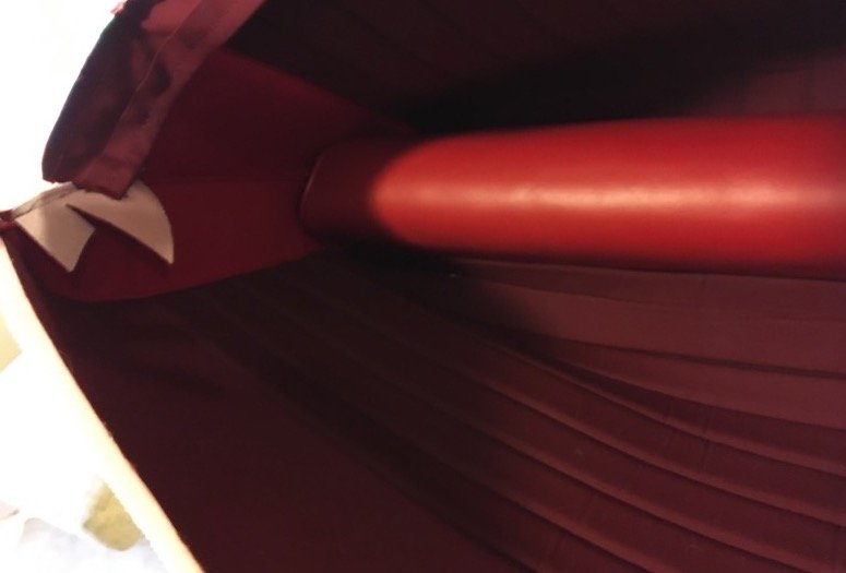
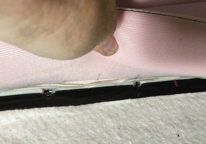
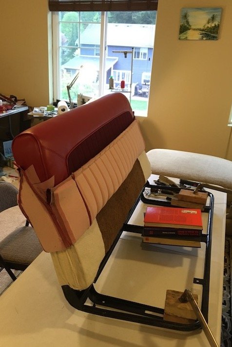
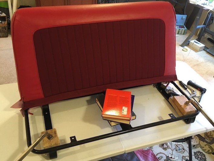
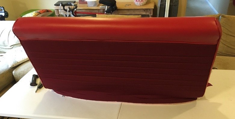
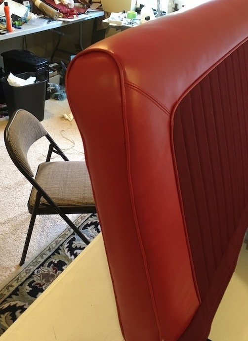
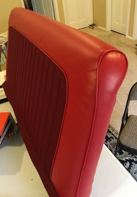
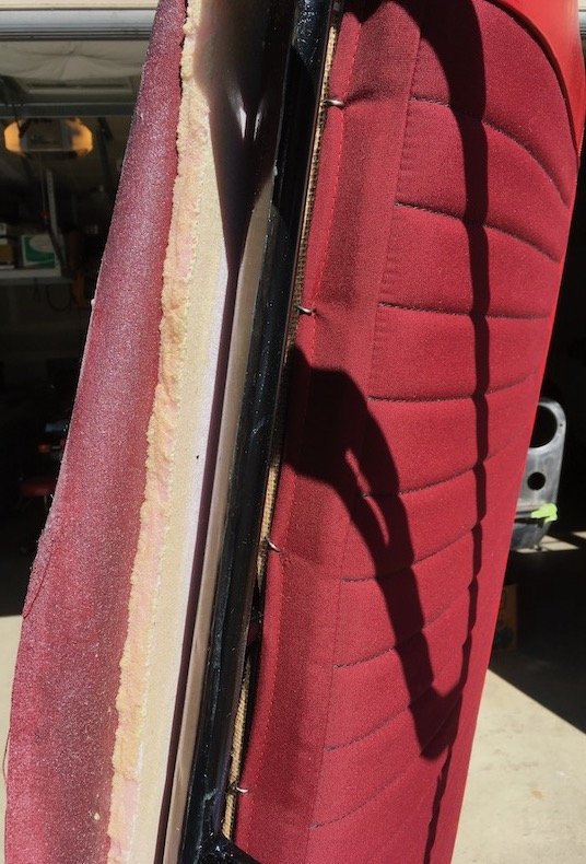
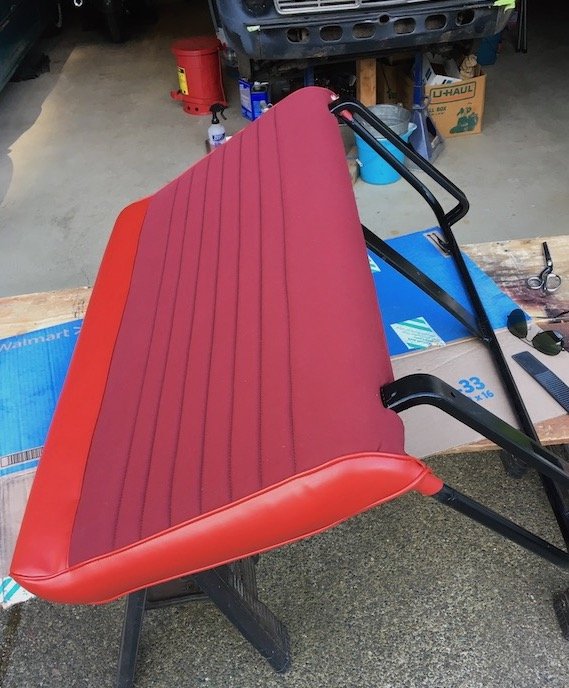
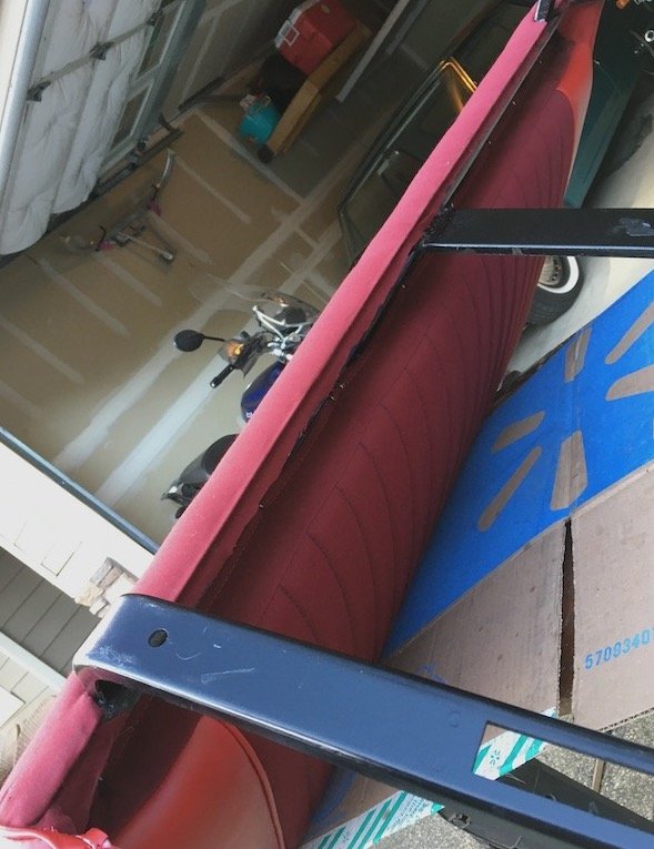
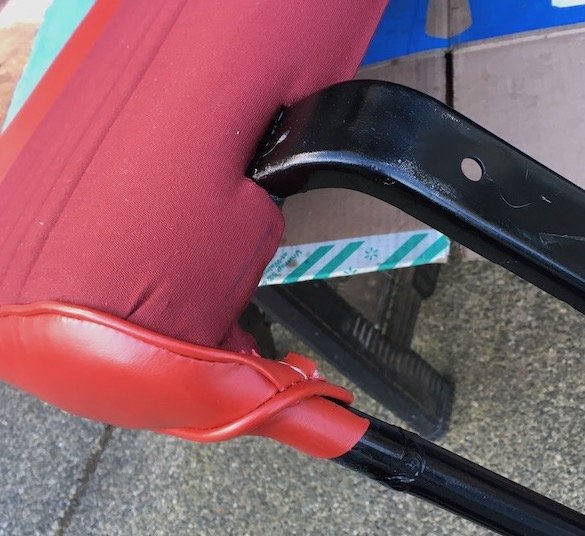
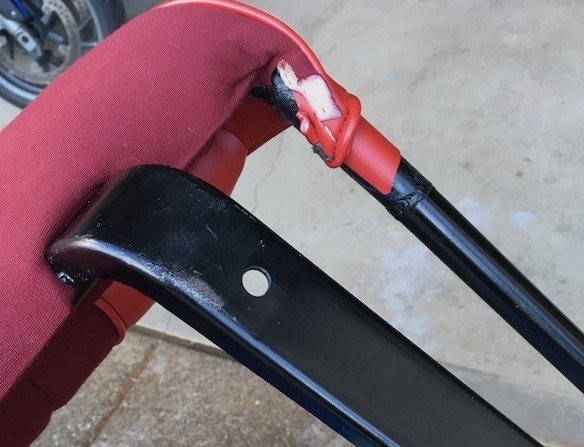
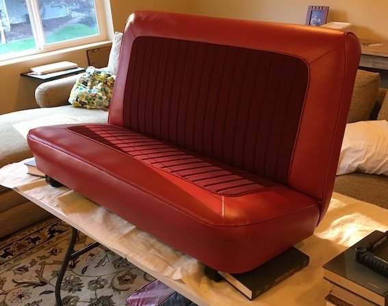
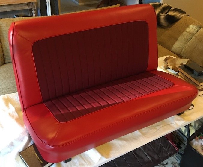
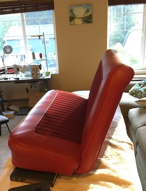
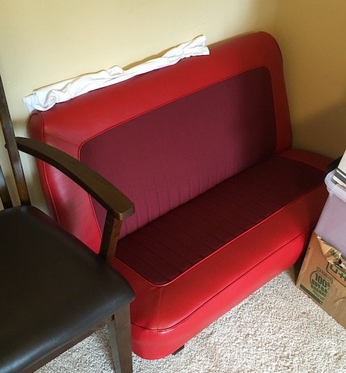
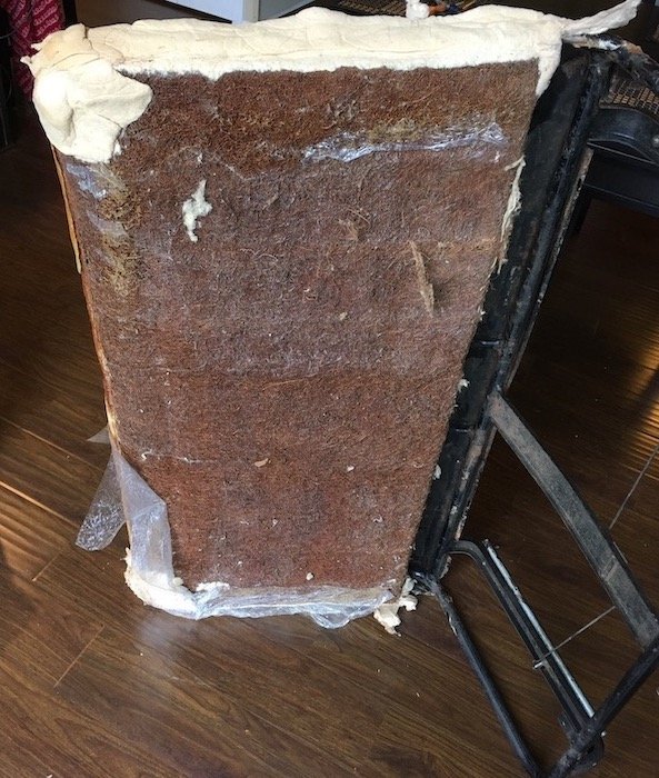
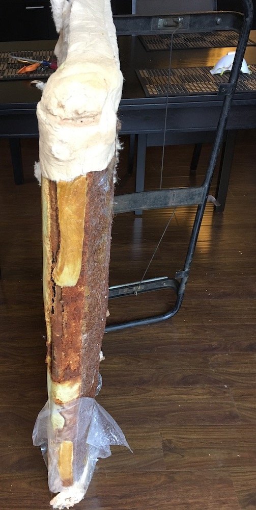
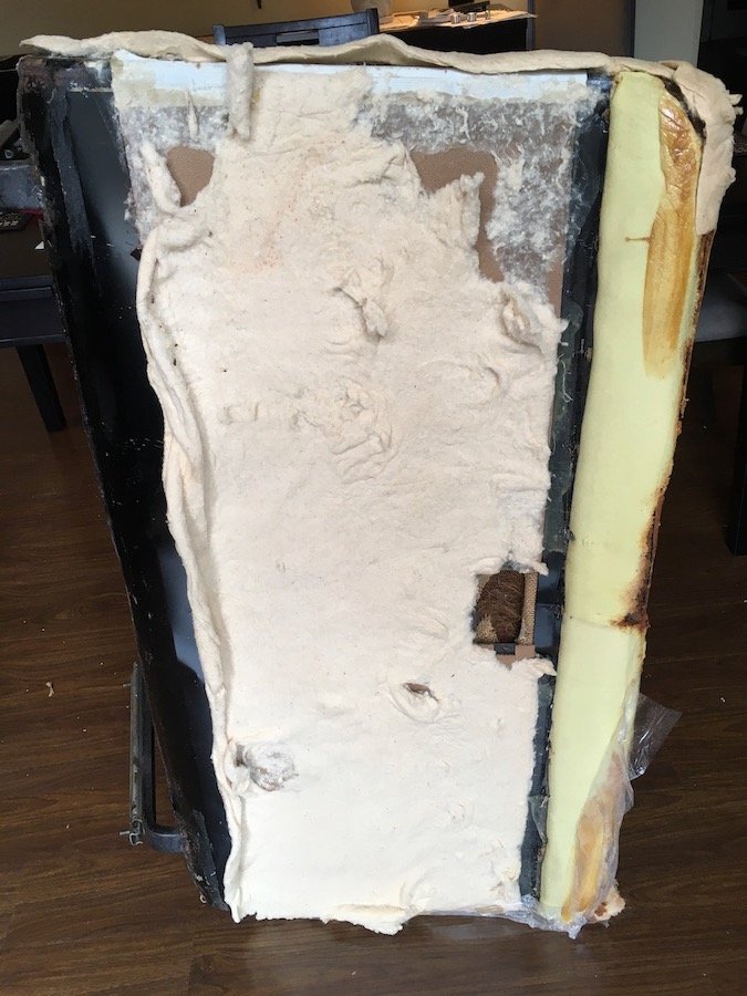
Building the 1961 Datsun 310 Bluebird - Upholstery Trimming Continued - Front Seat Backrest - Part 2. Picking up from Part 1, the backrest cushion of springs and layered coconut fibers was removed from the front bench seat frame. "Peeling back the onion." I began the research by deconstructing the 61 year old inner backrest assembly and peeled back the layers to see what's there. A very thin outer steel framework supports ten vertical rows of four coil springs each. For wrapping each row of coils, a layer of thin (now) coconut fibre cloth. Then on top of that delicate assembly is burlap cloth plus a flat layer of coconut fibre across the whole works. There were also strips of thin cotton batting and some foam rubber around the perimeter but that was removed before I took photos. On this the front side, it all has to go as disintegration has set in. The disintegrating mass is peeled back a bit further, with much of the material removed from the coils and thrown in the trash. I searched around and found some yard and garden shops that supply similar material called "coco liner." I purchased a tightly rolled bit and cut it up to layer each row of springs and attached it with hog rings at each end. Then new burlap cloth and coconut fibre liner of a flatter nature purchased from a local fabric store. Glued that down with Wildwood contact cement. Set that in the frame and progressed further by adding layers of cotton batting, and polyfoam to emulate what existed on the original. Initial layers of cotton batting. Attached the back hardboard. As far as it goes with respect to layering. I don't want it too thick, but just enough to fill out the seat cover with some tension and no voids. Glued the cotton batting to the hardboard same as original. Making the amateur Bluebird seat cover. Just a few detail construction photos as it was a little tough going to make it. Upholstery books and numerous internet videos demonstrate the process of reverse engineering the seat cover from the original as patterns. I just had a lot of difficulty with the upper corners that were rough on the original. In that case, I had to make some prototypes (masking tape version 01 then scrap vinyl version 02) and make adjustments to roll into the final patterns. Vinyl prototype version 2. Final production version going under the sewing machine. Some sewing challenges on those upper corners. A bit of a tight inside radius. The completed and ready to install seat cover. Beginning the install process from the seat cover inside out method and over the backrest top first. This is done rather than slide it over because of access required for a necessary listing rod to be clipped in places a few inches from the top and across the back to accommodate the concave shape. View from above as seat cover is slow massaged downward onto the backrest. Clipping the listing rod on the backside that is within a cotton sleeve of the cover. A bit awkward to perform but doable. Rolled about halfway down at this point. Then the adrenaline rose in me and I pushed a little too hard and fast resulting in a couple of small 10 mm long rips down near the bottom. Should be repairable though. It's on all the way now. Hog ring attachment of the front bottom edge to a rod on the frame. Contact cement applied to the backside and frame lower edges. All attached. Detail of corner attachment same as in photo of original with wrap around forward direction and then pinch into a metal frame clip. Another view of the rolled over fabric glued to lower frame sheetmetal edge. Some final views. Dropped in the previously completed lower seat cushion. Front seat assembly now resides in a bedroom serving as a potential lounger until the Bluebird floor is primed, sealed and painted. I'll post about the door cards next.
2 points
-
Easy. come get one of mine.1 point
-
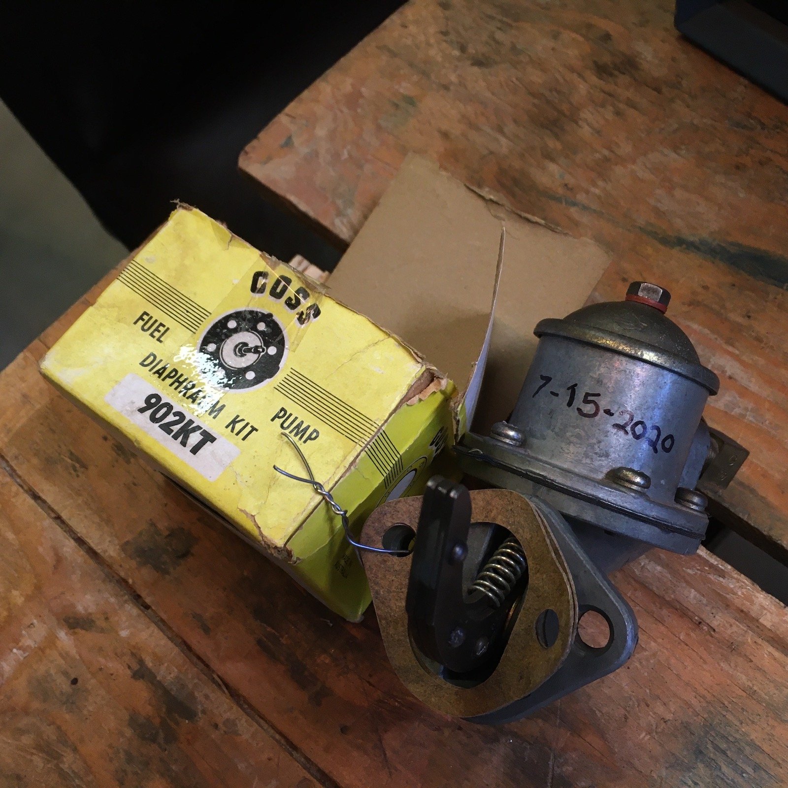
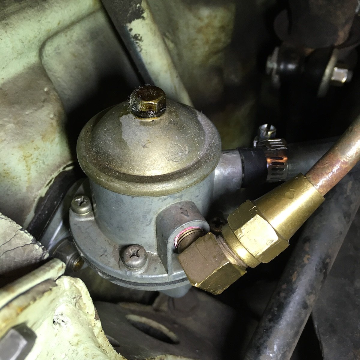
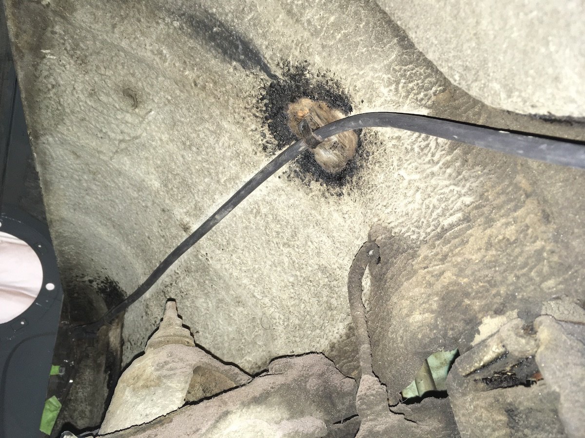
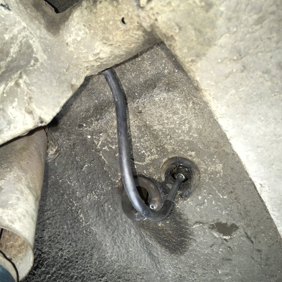
Building the 1961 Datsun 310 Bluebird - Fuel Pump and Supply Line. A fuel pump rebuild kit was found on eBay about 15 years ago, sourced from OZ. This kit was then assembled into the old mechanical fuel pump about three years ago and now it was ready to be used again. It was finally time to get rid of the cheap electric pump installed on the frame rail as a result of the mechanical pump diaphragm having been destroyed by ethanol blended fuel. It's not good when the old diaphragm ruptures and dumps a gallon or more fuel into the engine crankcase as it happened way back about 25 years ago. Now that the rebuilt pump is installed, I'm using only non-ethanol fuel in the Bluebird, sourced from a local farm and feed supply store in order to preserve the rebuilt pump. So far the mechanical pump is working good. The glass filter bowl (lower left of photo) is devoid of a filter element and it would be wise to correct this and maintain the original configuration without adding one of those cheap in-line plastic filters. Anybody know of a verified source for a Bluebird fuel filter that fits the original glass bowl? Showing the left front inner fender wheelwell and newly fabricated fuel line routing. The 1/4 inch steel line has been sleeved with plastic heat shrink along the entire length before bending. This matches the original factory steel line design that was protected against abrasion or other damage with a hard plastic sleeving. To the far left is the penetration into the engine bay and where the glass filter bowl is located on the other side. More of the same located under the left/rear floor pan between the inner sill and frame rail. One continuous line, along the original routing and clips, between the glass filter bowl and fuel tank. The new line at the fuel tank outlet connection. The thing next to the connection is the tank drain outlet spigot where I had previously drained out about four gallons of the old fuel. It was a bit challenging to bend the end here just right for a decent match and alignment to the tank connection. Also difficult to use a pipe double flaring tool in the tight area where I could barely fit my hands to do the job with one of those cheap tools meant to be clamped into a bench vise. At first, I was lying flat on my back having dirt fall on me and failing, then went at it from the side through the wheelwell opening where it was slightly easier. Ok, no more for this post. Now just to pop the seat in, lower the car and take a little test drive in front of our house. Some issues do arise, see next post soon.
1 point
-
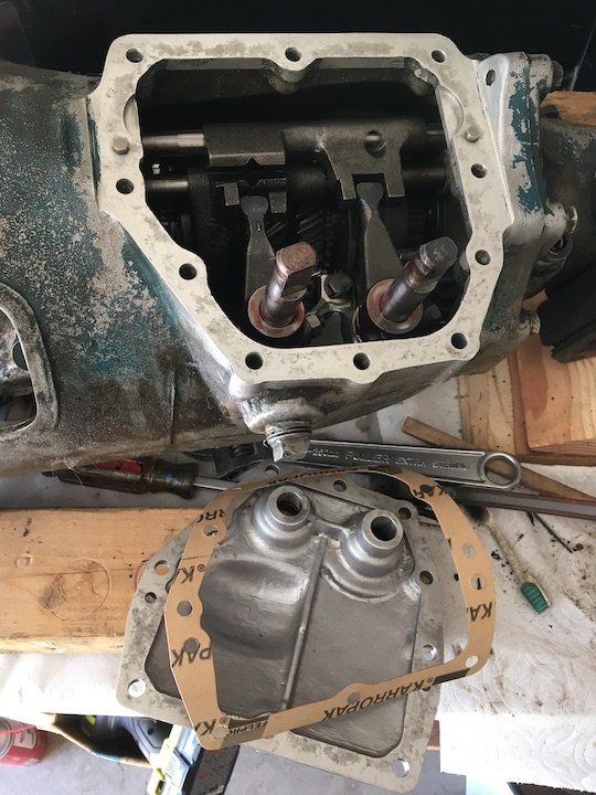
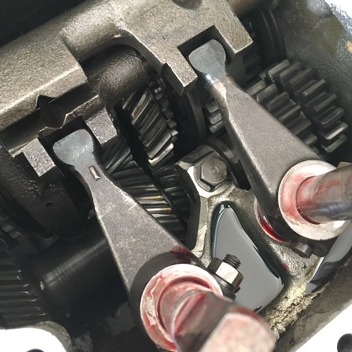
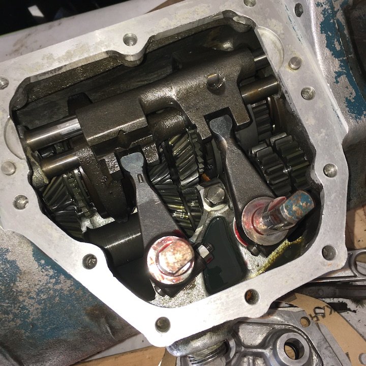
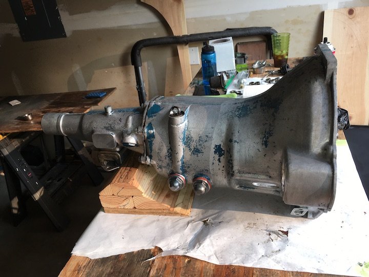
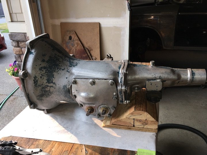
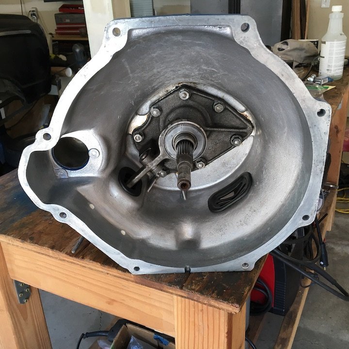
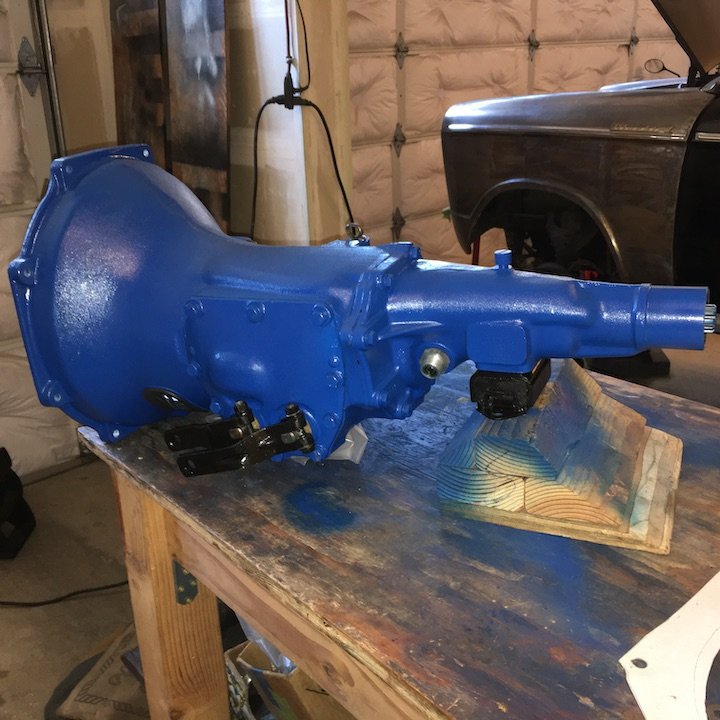
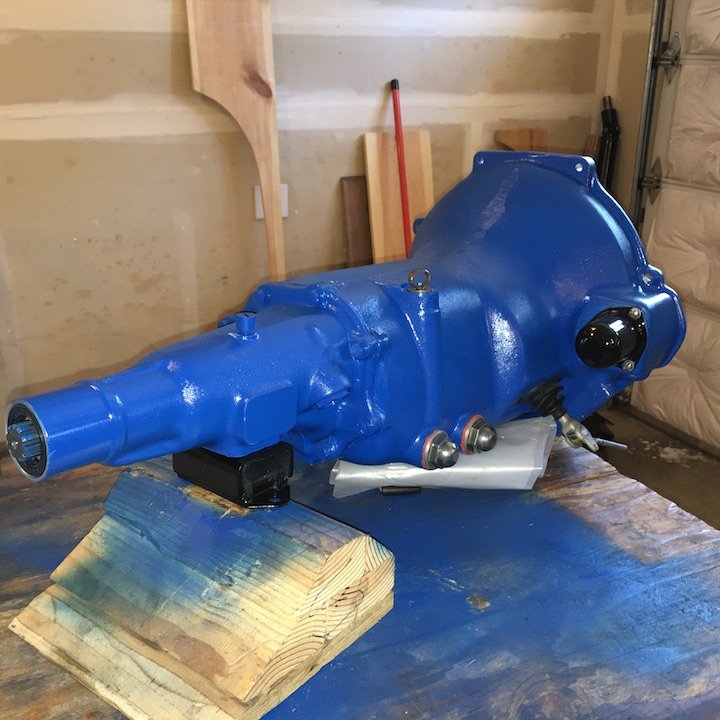
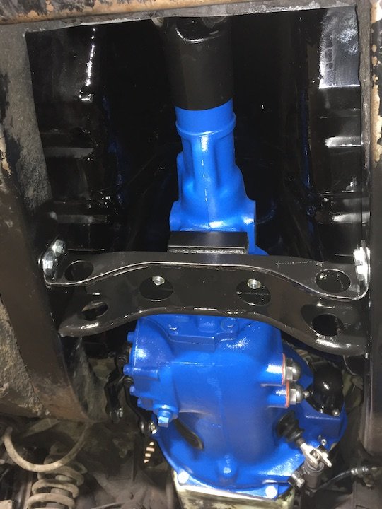
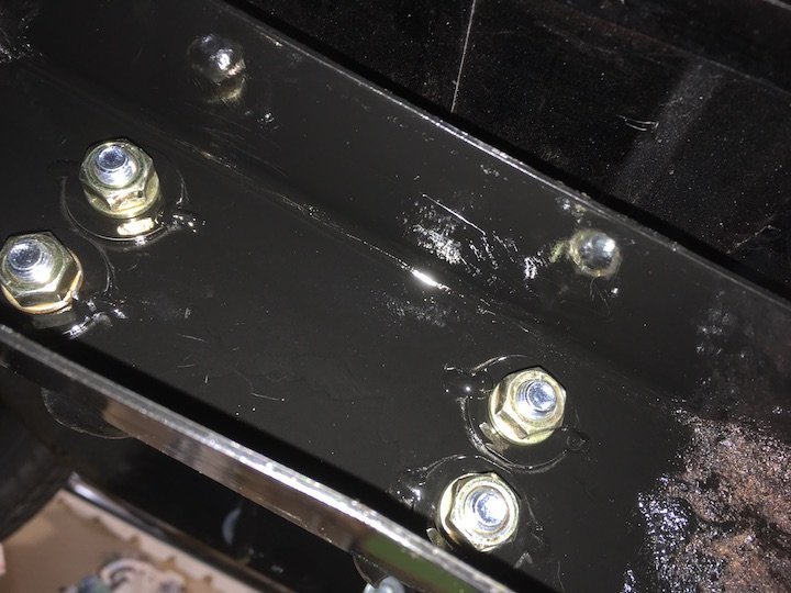
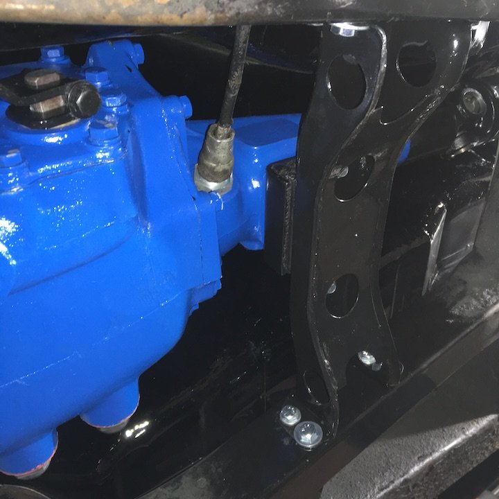
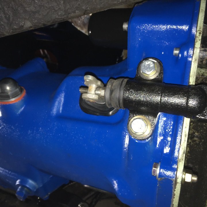
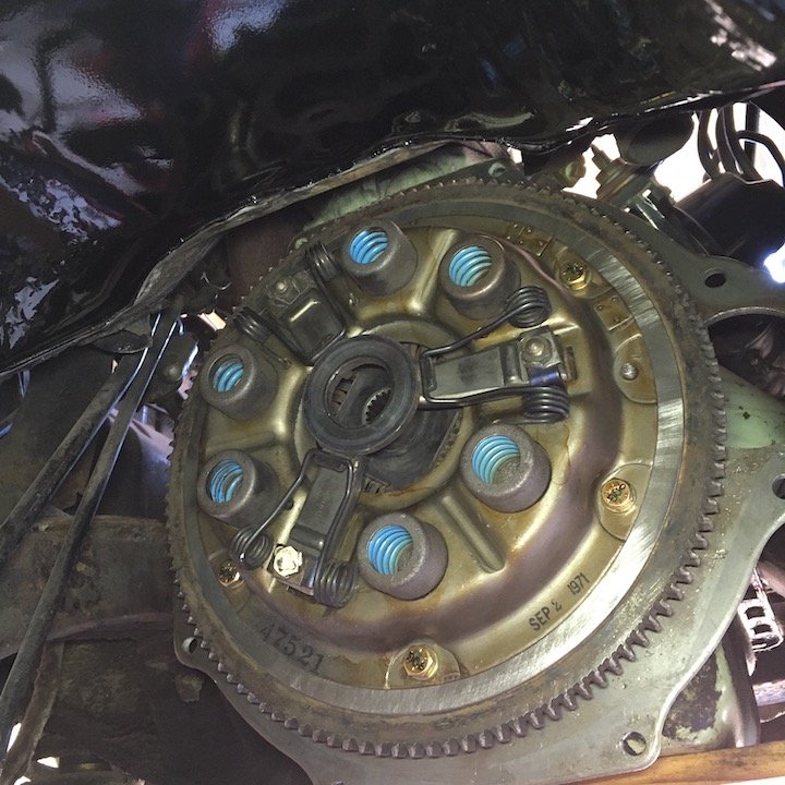
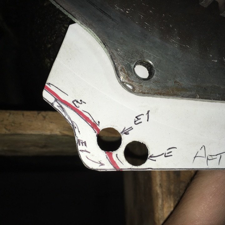
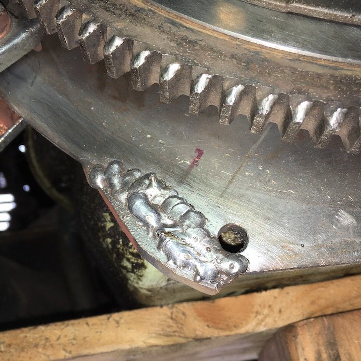
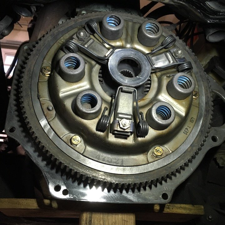
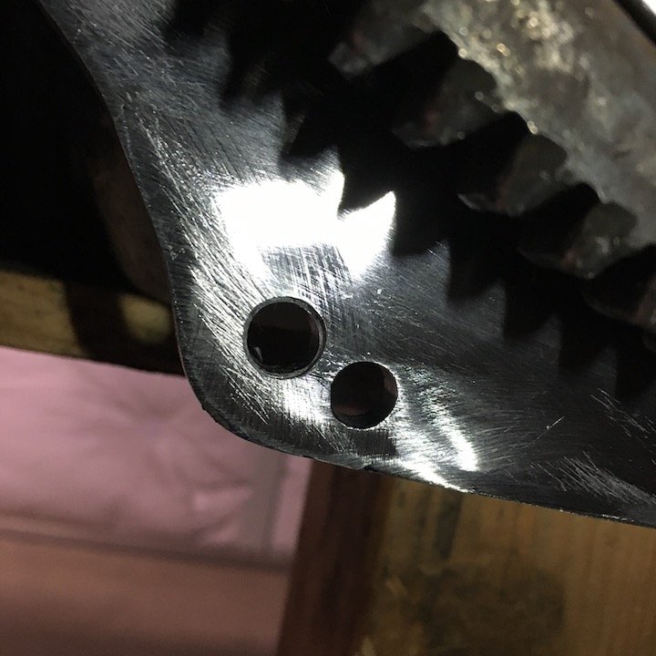
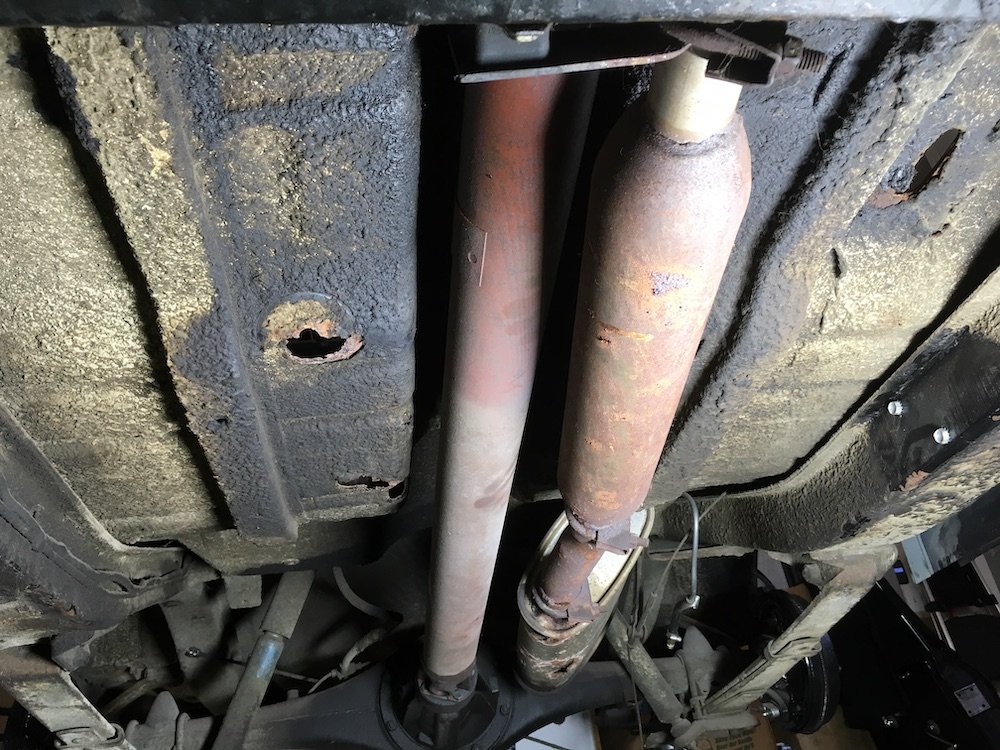
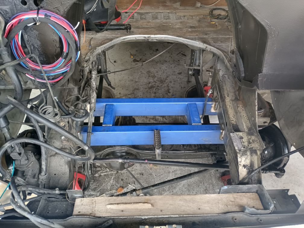
Building the 1961 Datsun 310 Bluebird - Drivetrain - Trans, Clutch, Flywheel and Driveshaft. Reinstalling the drivetrain included cleaning up, re-gasketing and sealing the three speed "full-SYNCHRO" transmission plus tuning up the driveshaft a bit. After cleaning the trans, I did a light disassembly plus inspection of the internals, sealed it up and painted. I did not fully tear the unit down as it had no obvious visual defects and worked well the last time the car was driven. If the trans ever does need any new hard internals such as bearings, synchros, etc., that will be a problem locating the parts. New gaskets were made for the front bearing cover plate, side shift input cover and tailshaft. Permatex Aviation sealer was used to dress the gaskets. The output shaft oil seal was replaced with new. The front input shaft does not use a conventional oil seal, instead it utilizes a labyrinth style or spiral grooved bushing ID to direct the lube oil back in, provided the outlet vent on the tailshaft is not clogged with dirt. The shift fork shafts were each previously sealed with a single double lipped oil seal. The double lip seals were hard to find in this size combination. Single lip seals were obtained from a hydraulics repair shop, and these were installed back-to-back (the open sides) at each shaft, to replace the original double lip seals. Finally, the speedometer drive o-ring was replaced and everything painted. Some transmission photos: The red stuff is engine assembly lube The red washers below on the small covers for the right hand drive provisions were reused, cleaned, sanded flat and coated with a thin layer of red high temp silicone. The P311/P312 trans x-member used here must mount approximately 4 inches further aft than the original P310 mount. Repairs to the two lower frame mounting holes, that had previously been hastily blow torched to match the "full-SYNCHRO" x-member, were made by tack welding washers over the lower rough holes and adding a pair of holes, with same washers, above to complete the full hole pattern as there were only half the bolts holding it together before. The clutch slave cylinder and hose were replaced with new parts. Still missing is the return spring The clutch cover, friction disk, flywheel and pilot bushing were all cleaned, inspected and are reused, except for new bolts. The old clutch cover bolts began breaking when torquing to the required 35 Lb-Ft. I do have a new clutch cover and disk but will keep those in reserve if ever needed. Note date on cover, SEP 1971. Mods to the engine-to-trans adapter plate: The engine-to-transmission adapter plate was modified slightly. The current installed plate was designed for the old non-first gear synchronized transmission as was supplied with the "E" 48 Hp engine. This plate has a different hole pattern and one lower left hole does not match up. So I made a modification that allows either transmission to fully bolt up by adding some metal and the necessary hole for the "full-SYNCHRO" trans. Before profile comparison After rough MIG welding new metal plate using a wide v-groove and a generous build-up Finished. Now it is a multi-trans adapter plate for either the non-synchro (first gear) or full synchromesh trans. Driveshaft saga The driveshaft u-joints were removed and the shaft and yokes were stripped back to bare metal, painted and one new u-joint installed at the front because I lost one of the needles during disassembly and cleaning. Now, the other joint on the aft end will be replaced because it was mis-assembled by me. I clocked the yoke 90 degrees out of phase with respect to the grease fitting threaded hole. I didn't realize the yoke had a clearance scallop specifically to permit install and removal of the grease fitting. Since I have to remove it to correct this mistake, then I might as well match it up with the same replacement u-joint installed on the front. It's packed with new grease for now so no rush. New bolts used of course. Old driveshaft installation long before floor repair and exhaust removal. A "temporary" electric fuel pump had been mounted to the right where you see the two bolts on the cleaned frame rail. Might have been a disaster if fuel began squirting out at that exhaust pipe! This was NOT the correct factory exhaust design for the P310 btw, especially the horrible support at the frame x-member pass through hole I'll post photos about the installation of my rebuilt mechanical fuel pump and new fuel line next. After that, the car is lowered to the ground for the first time in six years to do a little very rough and loud first test run.
1 point
-
Nothing of value to add here other than encouraging you to do this silly idea. We tried a woodstock/diesel powered 4age once. Was a bit low on compression and had a headgasket issue. 7%RON was obviously no good. 8% or 11% Cody's would have done the trick I'm sure.
1 point
-
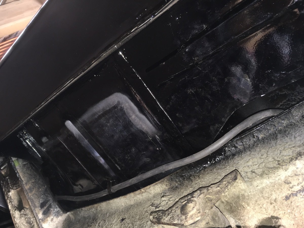
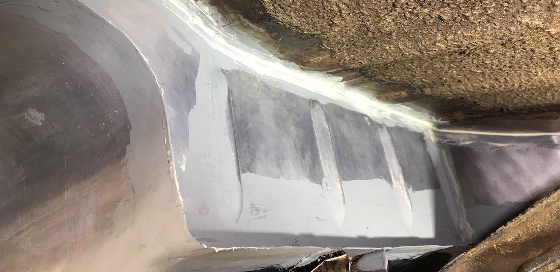
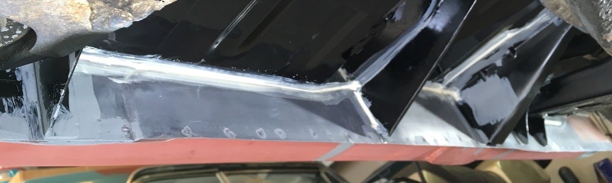
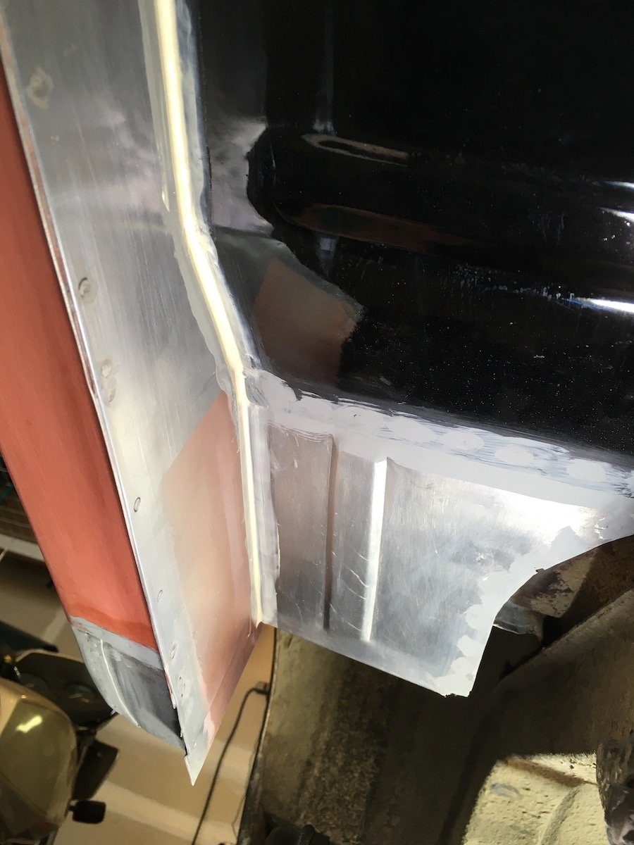
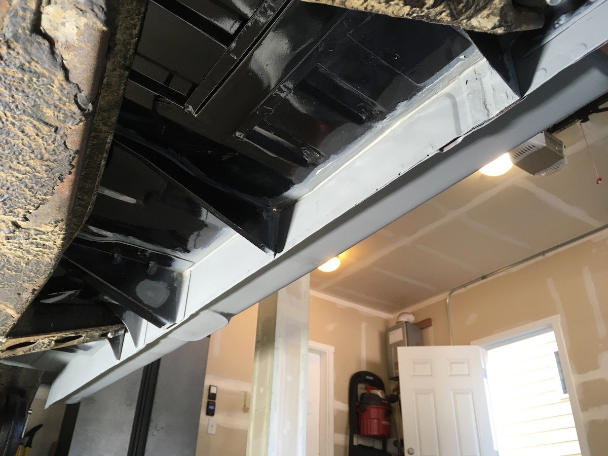
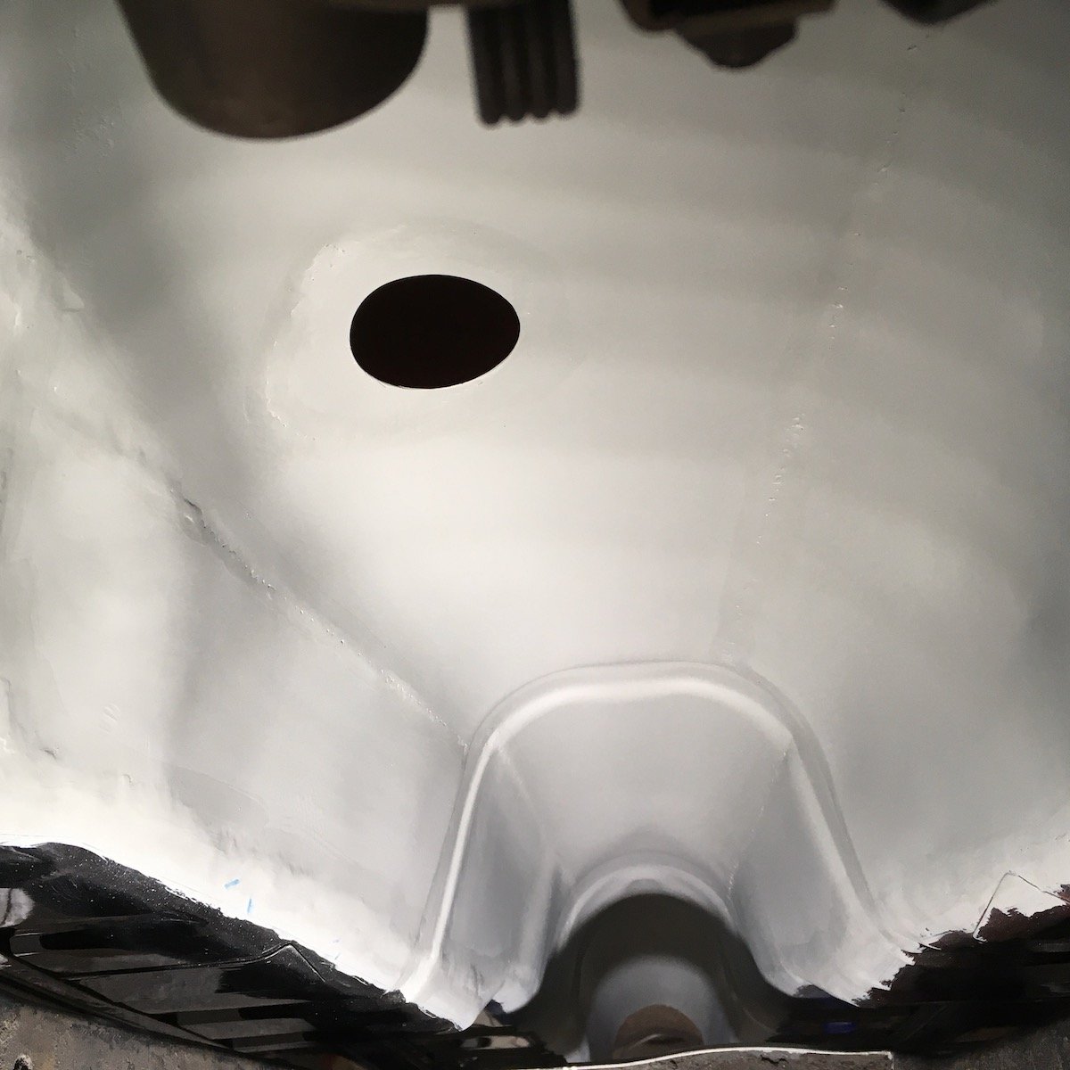
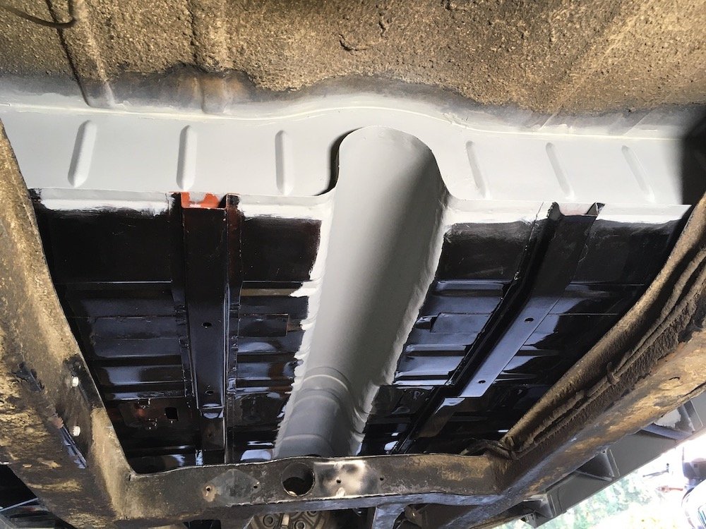
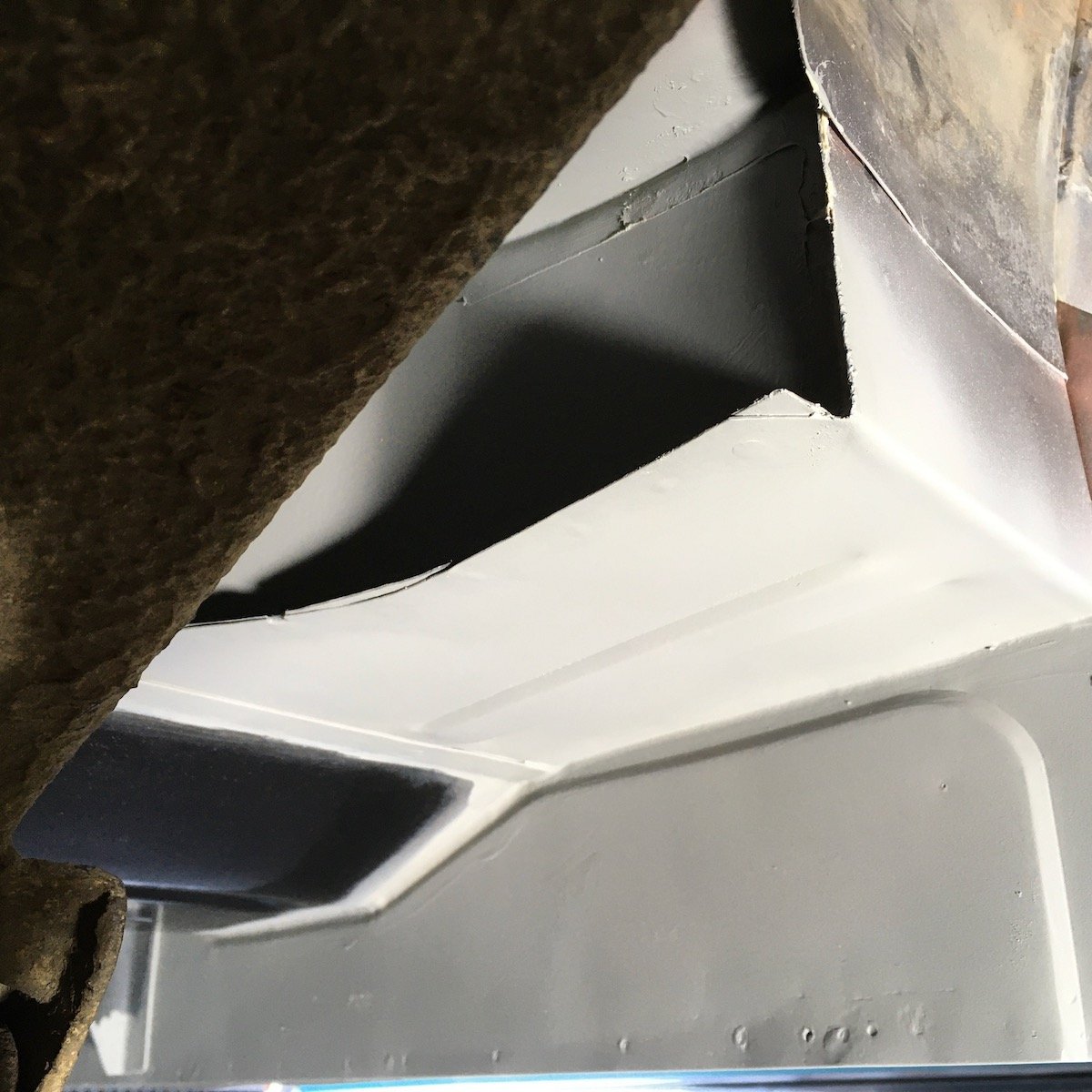
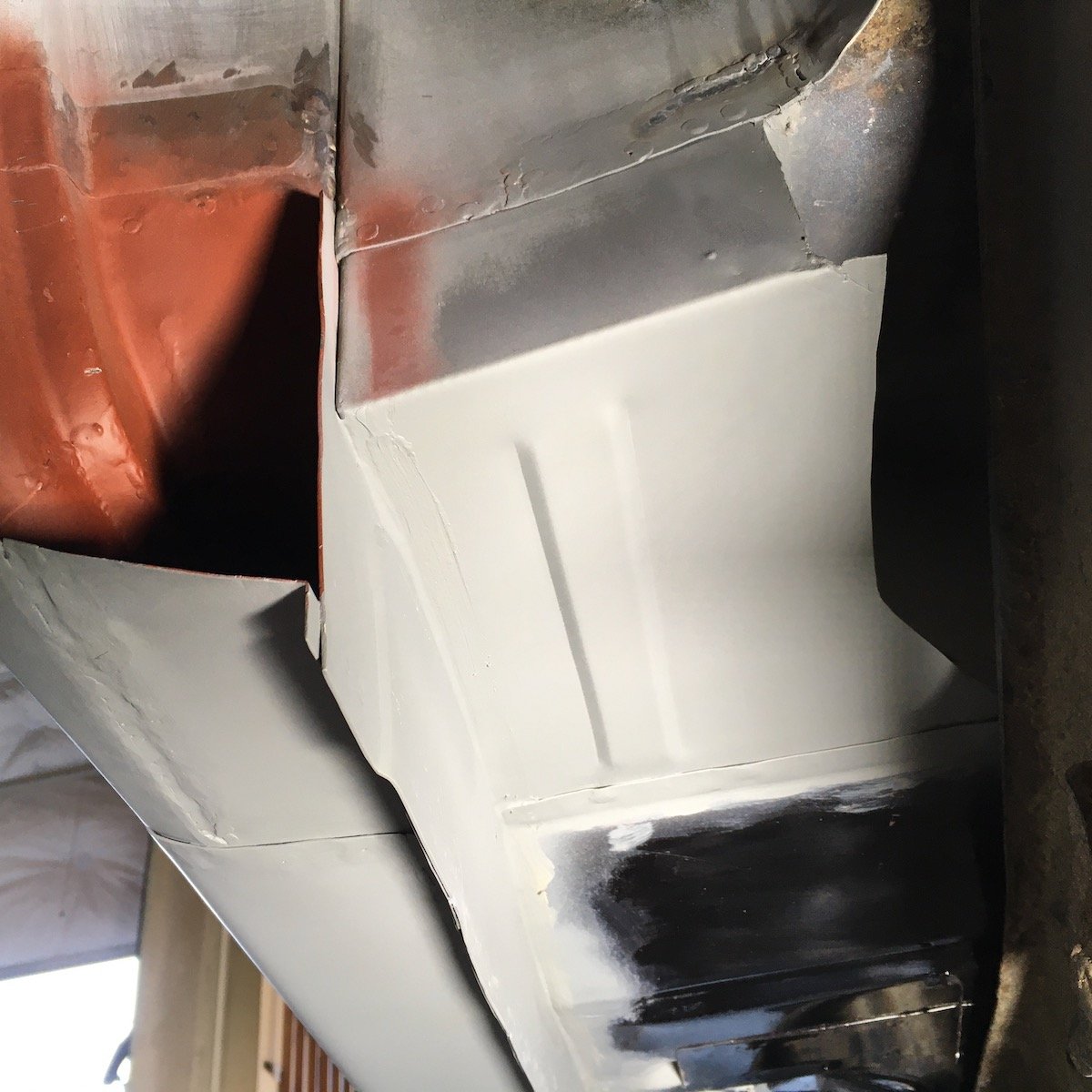
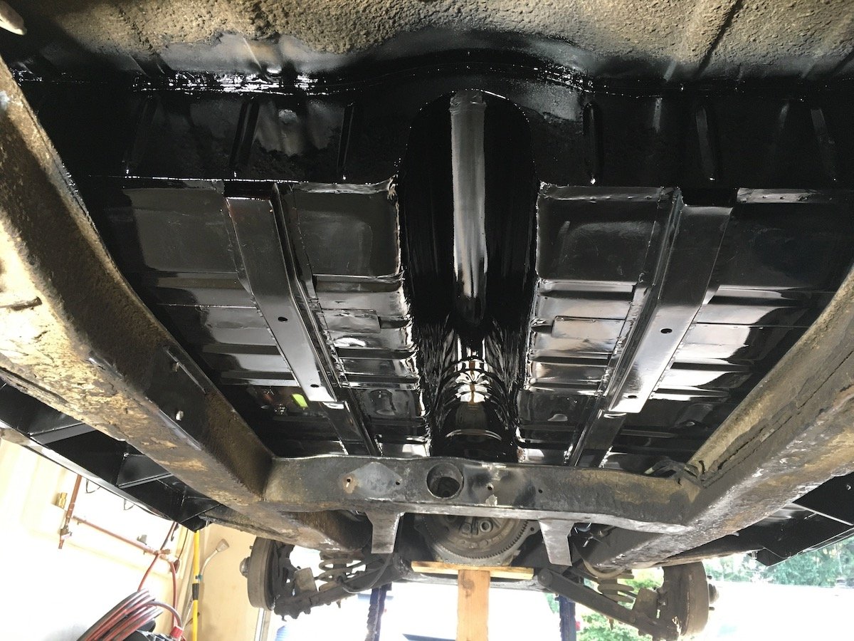
Building the 1961 Datsun 310 Bluebird - Underside Paint Preparation I'm back on the Bluebird project, beginning again in July, after spending eight months sorting issues on the 79 VW Bug convertible just to get it to a reliable driving state. About a dozen or so NZ OS posts to follow covering the last two months of intense effort. Main goal was to get the car moving again under its own power. Second goal was to paint the top side of the completed floor pan and adjoining interior areas. Lots of detail work was completed to accomplish both goals. There's tons more work to do including installing headliner and the front and back glass. Backing up a bit from the last post in October 2022 showing the completed underside paint, shown below is some of the preparation that went into that final coating to minimize future rust. The remaining bare metal was chemically cleaned, etched and zinc phosphate coated. Then brush epoxy primed on seams and significant weld joints, followed by seam sealer application and full epoxy prime spray. Aft end of floor pan and tunnel looking forward Tunnel looking aft Right side inner sill looking aft Left side inner sill looking aft Done with the direct underside finish as shown last October. Other adjacent areas may be addressed with a future exterior repaint. Next post will be photos of the trans refurbishment and install to finally get the car off the jack stands and moving again.
1 point
-
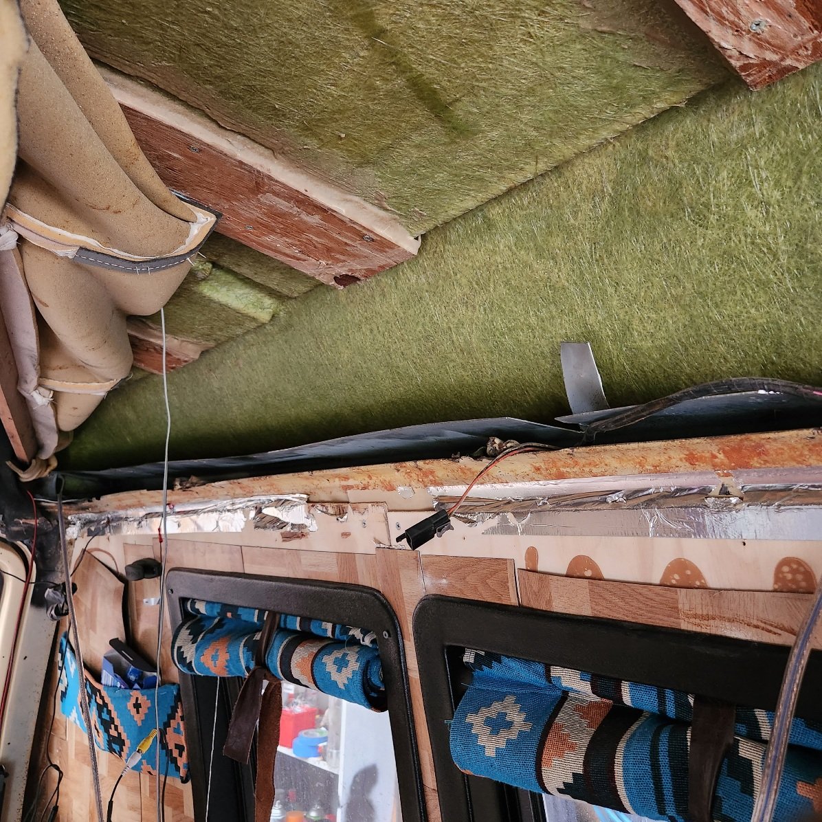
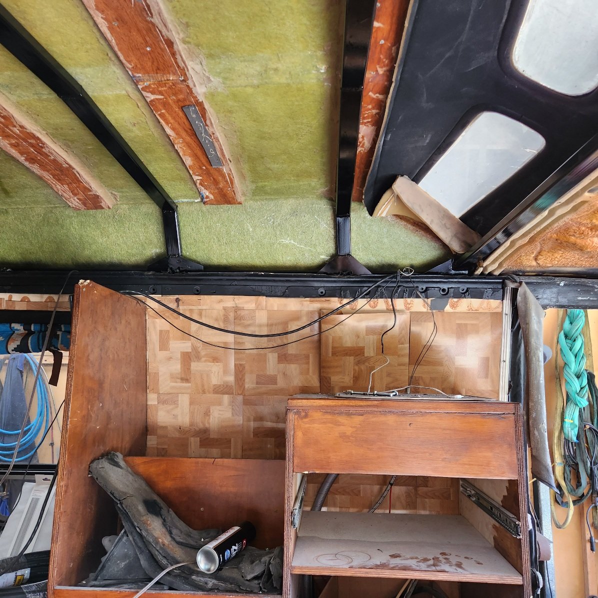
The roof bracing is mostly done, I won't attach it until certifier has seen it again, he was talking adhesive and rivets, I want to use bolts. It's definitely a bit tidier, before : After This will all be upholstered over anyway I also got the floor and front lined, roped the grommet into it for the corners, up under the pedals, worst $10 she's ever earned And the wheels showed up, it's just how I pictured. Plenty of clearance inside at front, and close to flush with guards, out back I might have to space them out a touch, theres not much clearance with inner fender, will see how it goes with flex.
1 point
-
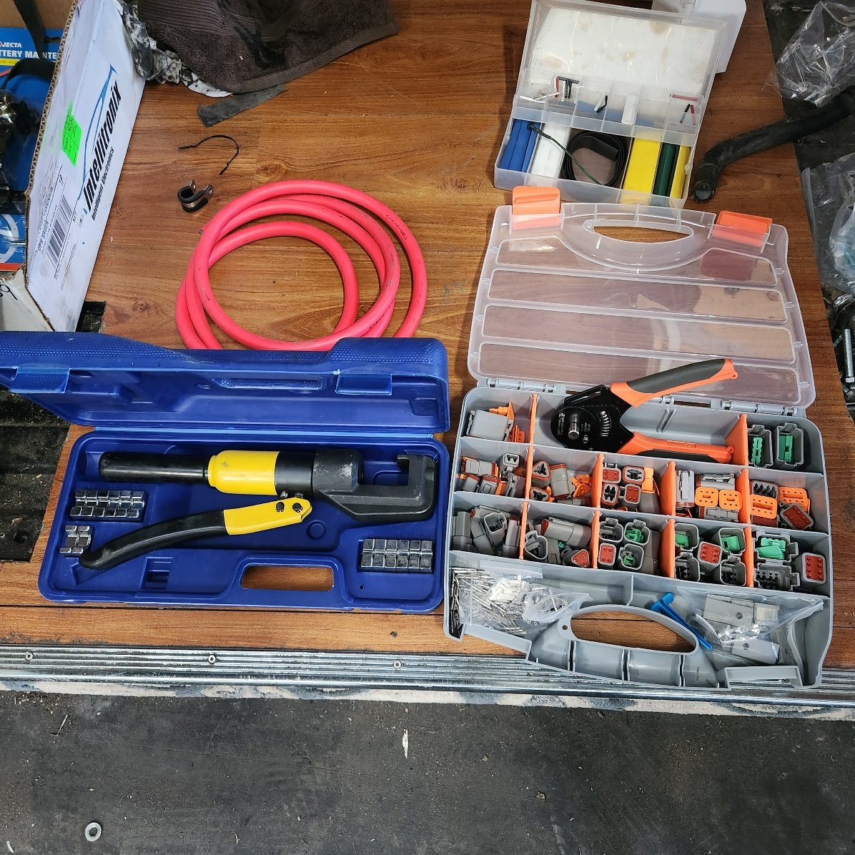
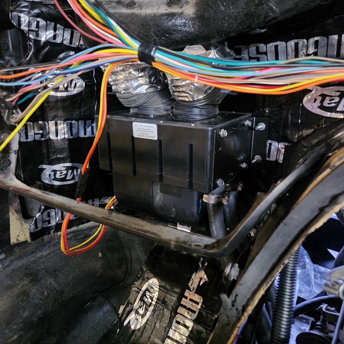
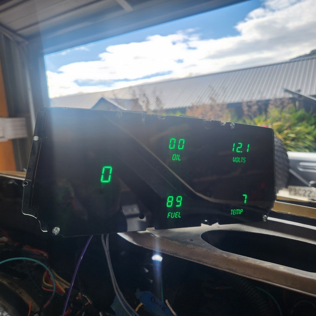
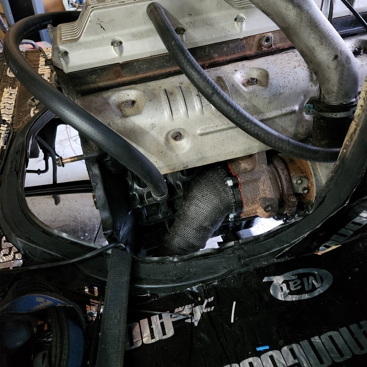
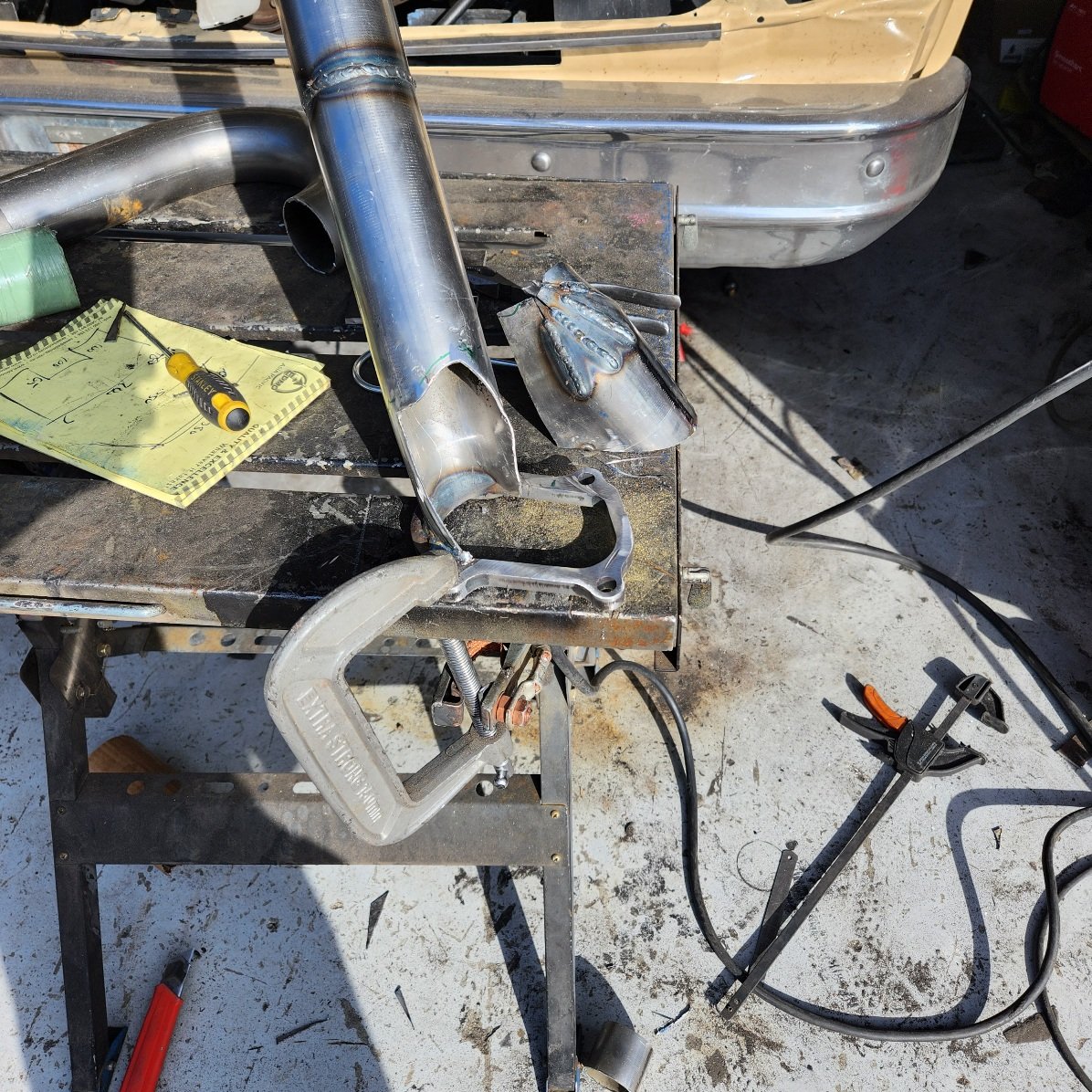
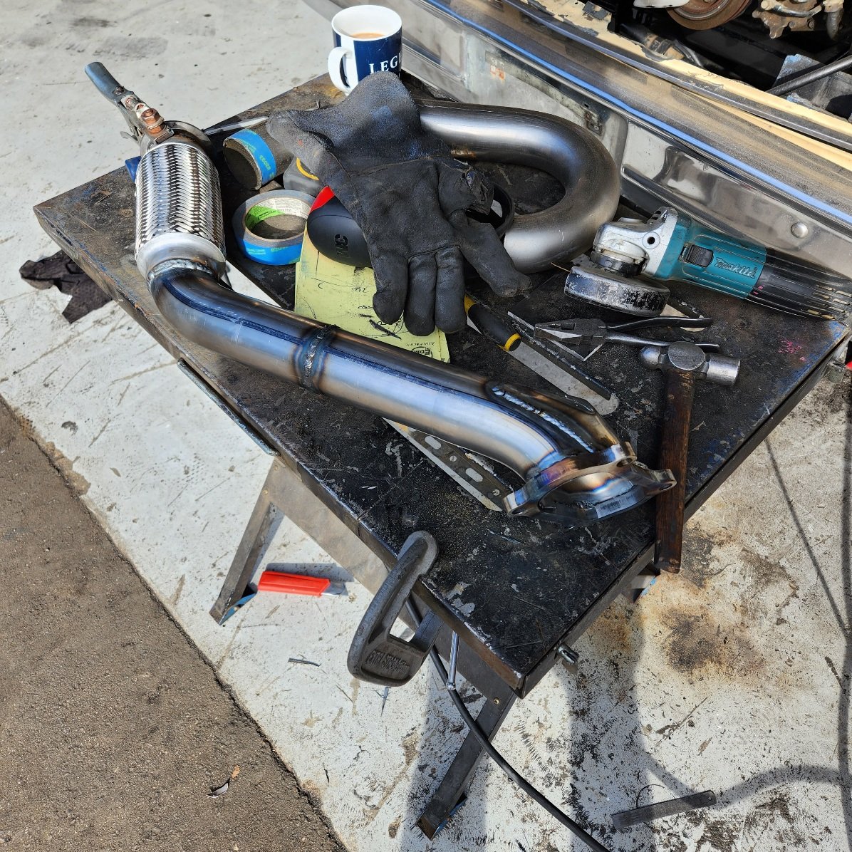
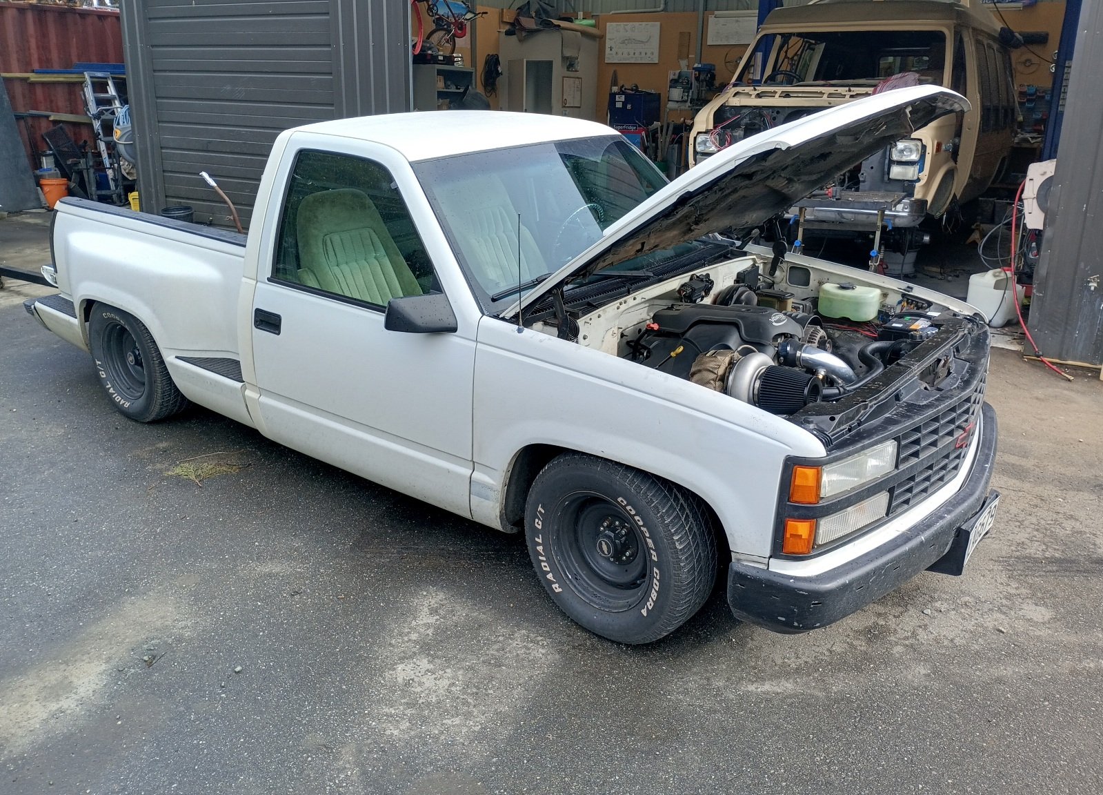
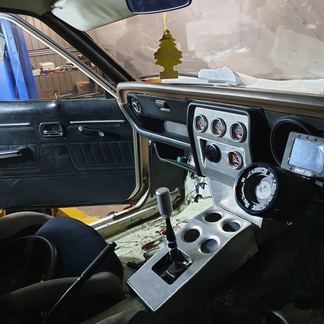
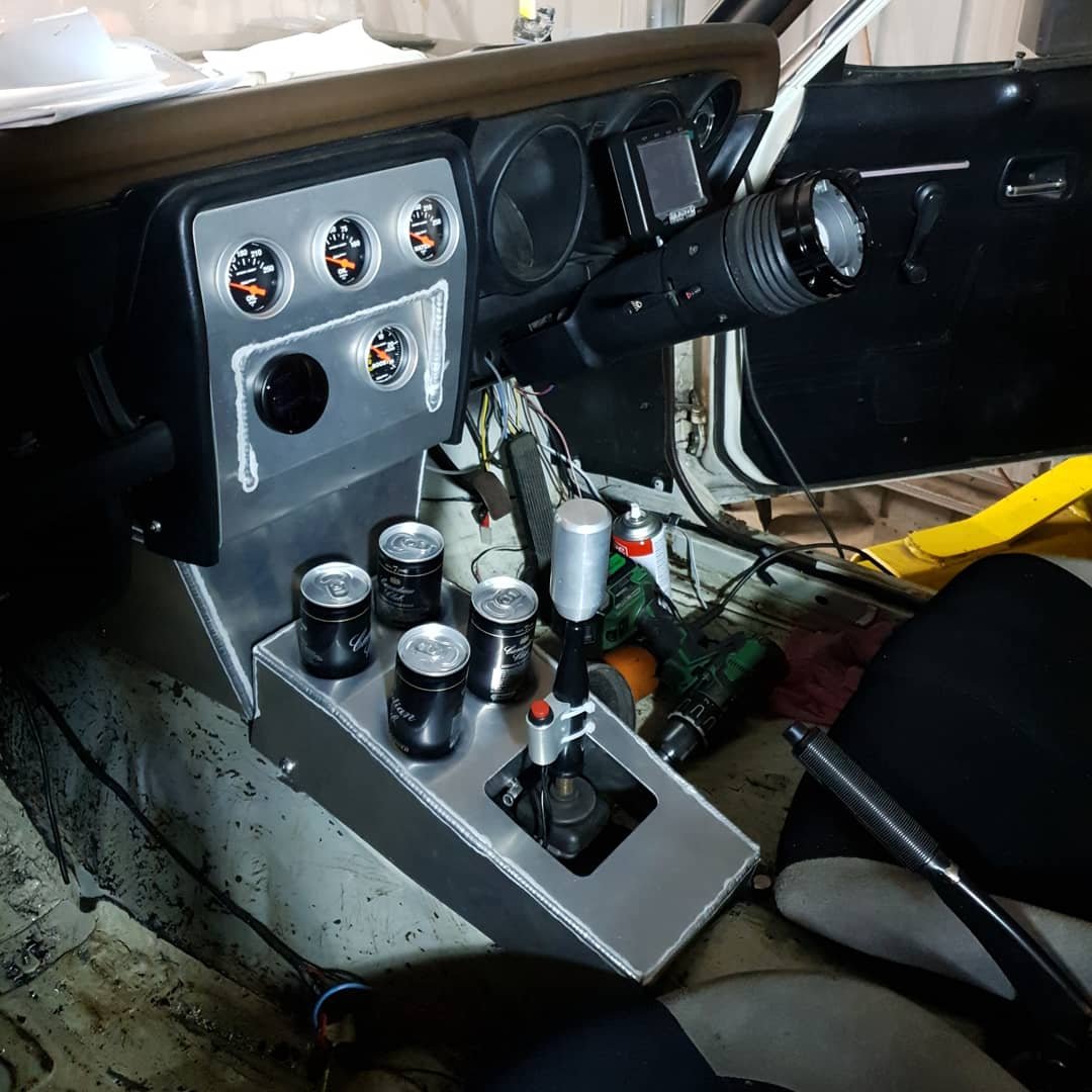
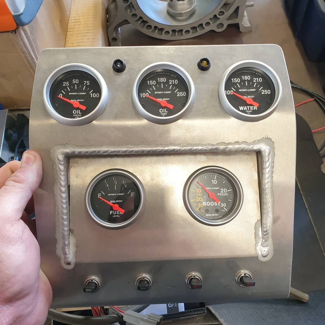
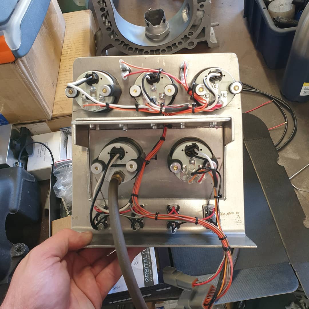
I've had a good bit of progress last week, got a good chunk of wiring sorted, shout out to my favourite tools, my hydraulic swager for 0 gauge cables and my temu Deutsch plug kit I got the heater in, it's just a universal Summit one, I got rid of the distribution manifold and everything and just plumbed it straight into the demister rather that trying to revive a heap of vacuum operated valves and nasty old crap I also got the dash fired up, pretty pumped on it I got the dump pipe made up, its nice not having a firewall to argue with, it's 45 degrees out of the turbo so I didn't bother with steam pipe, it's basically full lobster back tif welded SS, except with mild steel, and a mig, and out of combo bends it fits good
1 point
-
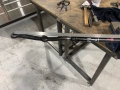
would be interesting to see the whole curve on them. if the kelfords open the valve faster to the first mm. do they continue on accelerating the valve faster, getting to higher lift faster? This is an interesting pic that shows the numbers shown, only tell a small part of the story. left is a 318/11mm right is a 320/10.8mm pretty much same on paper with the advertised measurements. not so much when looking at them.
1 point
-
Thanks. I'll send you some pics of what it looks like. It looks pretty cruddy though so I might give it a good clean first and see if that's all it takes. Also trying to sort shipping on these: Seller is making it tricky to know a price however. Look at the questions: https://www.trademe.co.nz/a/motors/car-parts-accessories/subaru/engines/listing/42890593411 point
-
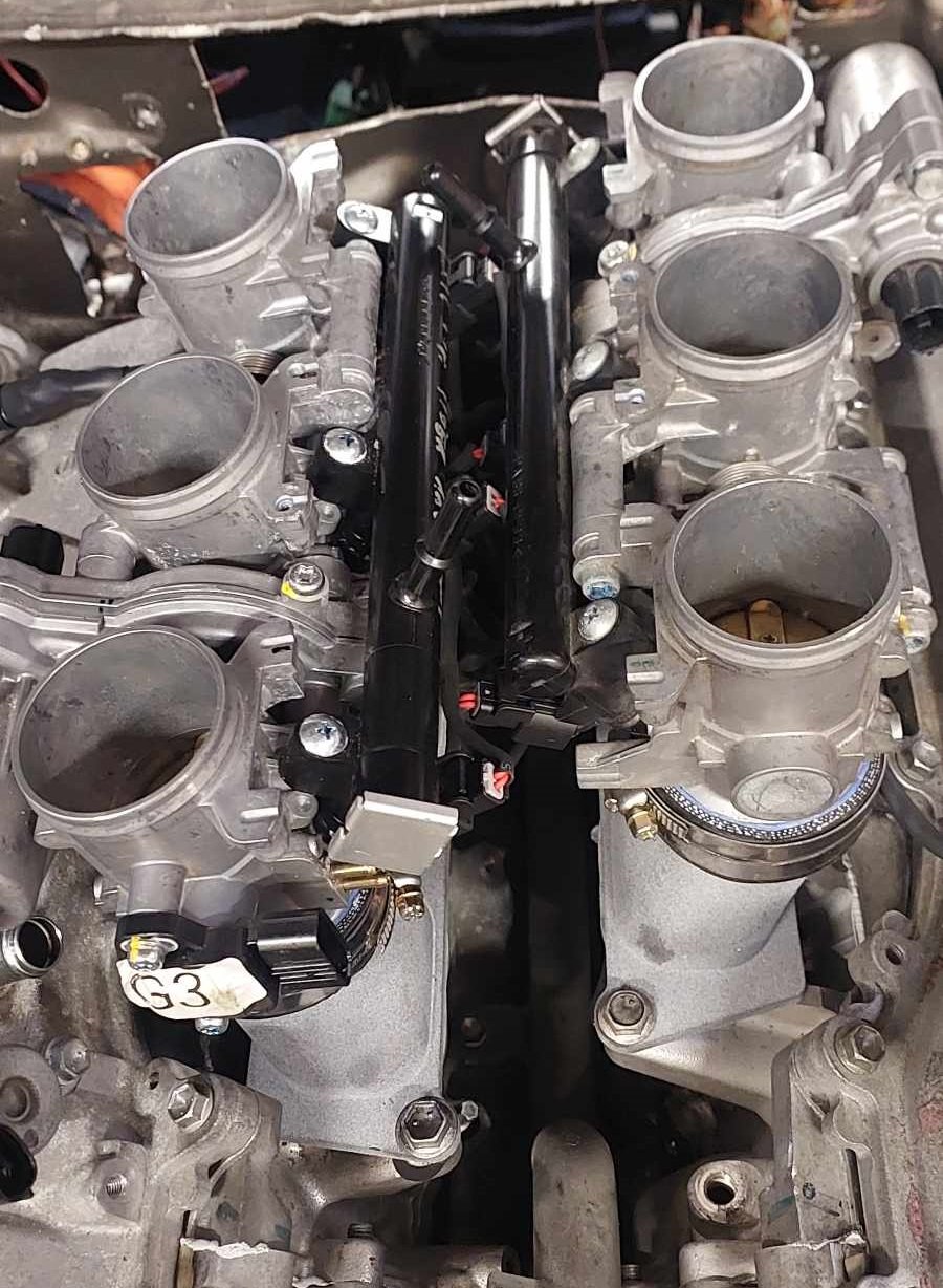
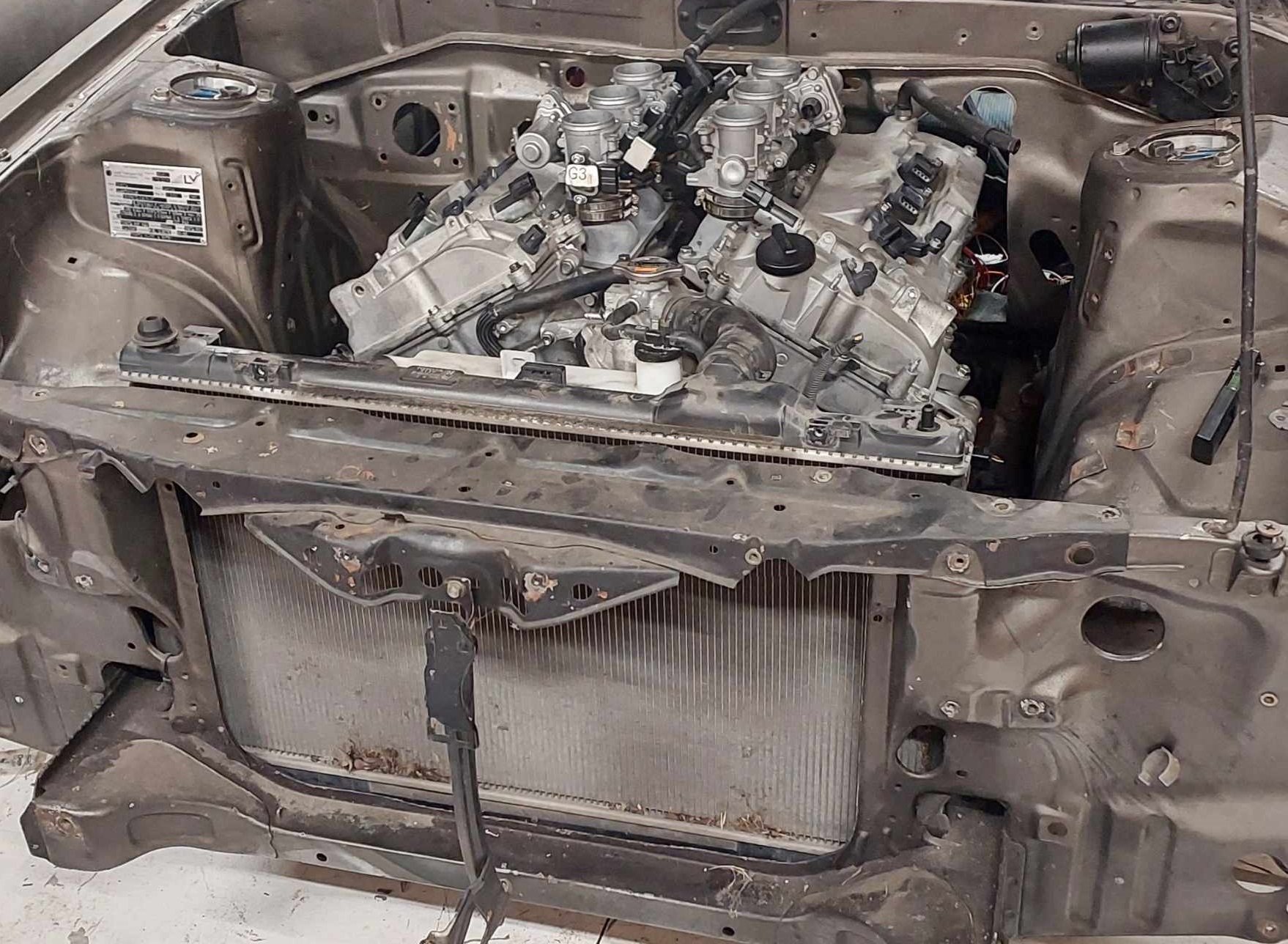
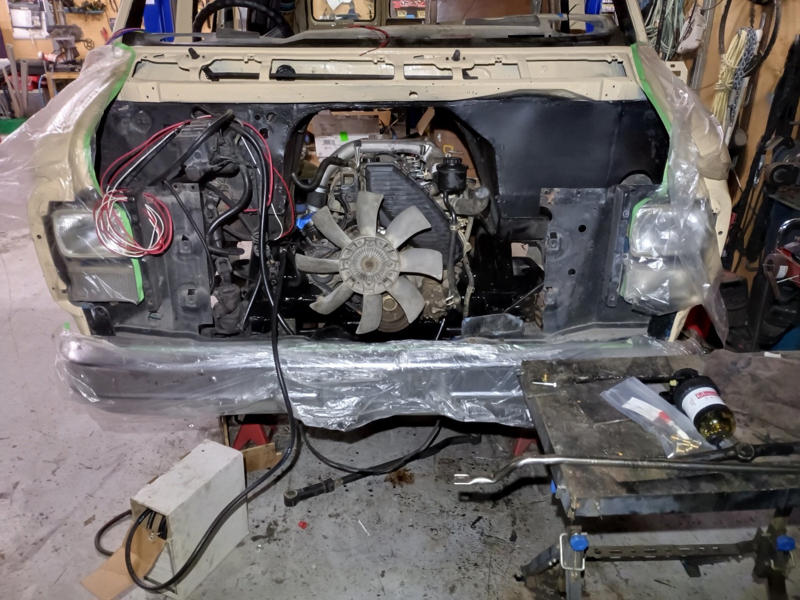
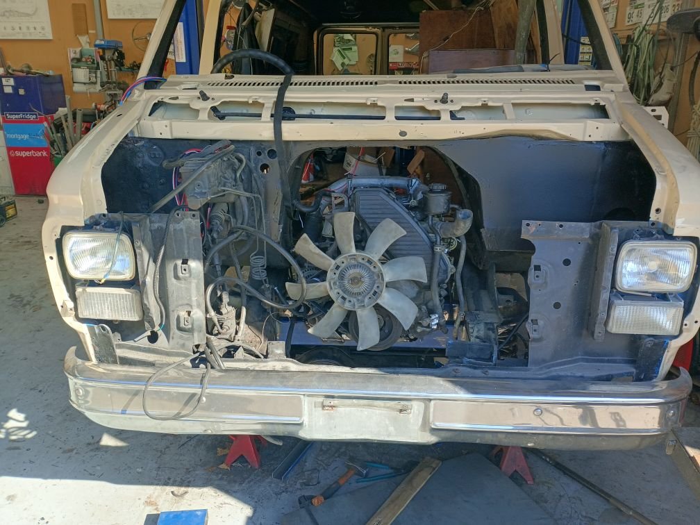
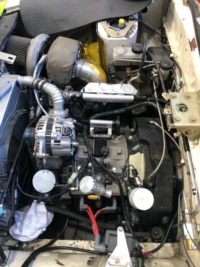
Some good progress! I got Kelford valve springs and retainers fitted (with many swear words) The heads torqued down, cam timing done, (standard cams for now) and front cover gooed in place. Bellhousing is now fully welded, but I havent swapped this onto the proper box yet. So back in the hole, then accessories fitted, all covers etc back on, throttles on, coilpacks in. Then I thought I'd have another try at fitting the Mark X radiator, that I bought from pickapart a while ago. As it really would make life easy if it works. Well, it sort of does! Sorry for potato pic. There's enough height for it to fit without hitting the bonnet, and I could make mounts for it to sit so the factory pipes work okay. Which would be awesome, as I usually end up with a mish mash of cut and joined pipes on car projects. But there's one issue. The radiator cap is mounted on the outlet on the engine, not the radiator. So in factory config, the motor sits higher than the radiator. Mine will be opposite. As I cant move the radiator any lower, but the engine will sit a little lower than current position. I'll end up splashing coolant everywhere if I take the radiator cap off, and probably wont bleed all the air out. So the options are that I could run an inline radiator cap in the top hose near the radiator. (Which will look gumby) Or otherwise cut the front housing and reweld the cap a little higher up, so it's at the highest point of the cooling system. But the pipe angles might still cause some bleeding issues. It's damn close to being a good solution, and there are aftermarket Mark X radiators available if it needs more cooling. So I'd like to run it all like this if I can figure out a good way to make it work. Next on the list while a few other parts are still in the works, is to start on wiring. So I'll need to decide where to mount the battery, and then test if it has enough grunt to crank the motor over. This engine doesnt have variable reluctors for the crank angle sensors, like every previous Toyota engine I've had. It has 3 wire hall effect. So this means I can probably get a good rpm signal at a lower rpm than VR sensors. Which might make start up time and cranking a little easier on the battery. As the VR sensors seem to need to get up to say 600rpm or there abouts to register a high enough voltage. One annoying thing though, is these sensors output quite a low voltage. So to get them working with link ECU, need to wire in some pullup resistors. But, I've got a solid plan for how it's going to work this time. I'll lead most of the wiring into the vee under the throttles. I might print a little cable tray for that area, with just small branches coming off rather than a big trunk. To allow for the inevitable loom meddling I'll be doing later on for whatever reason.
1 point
-
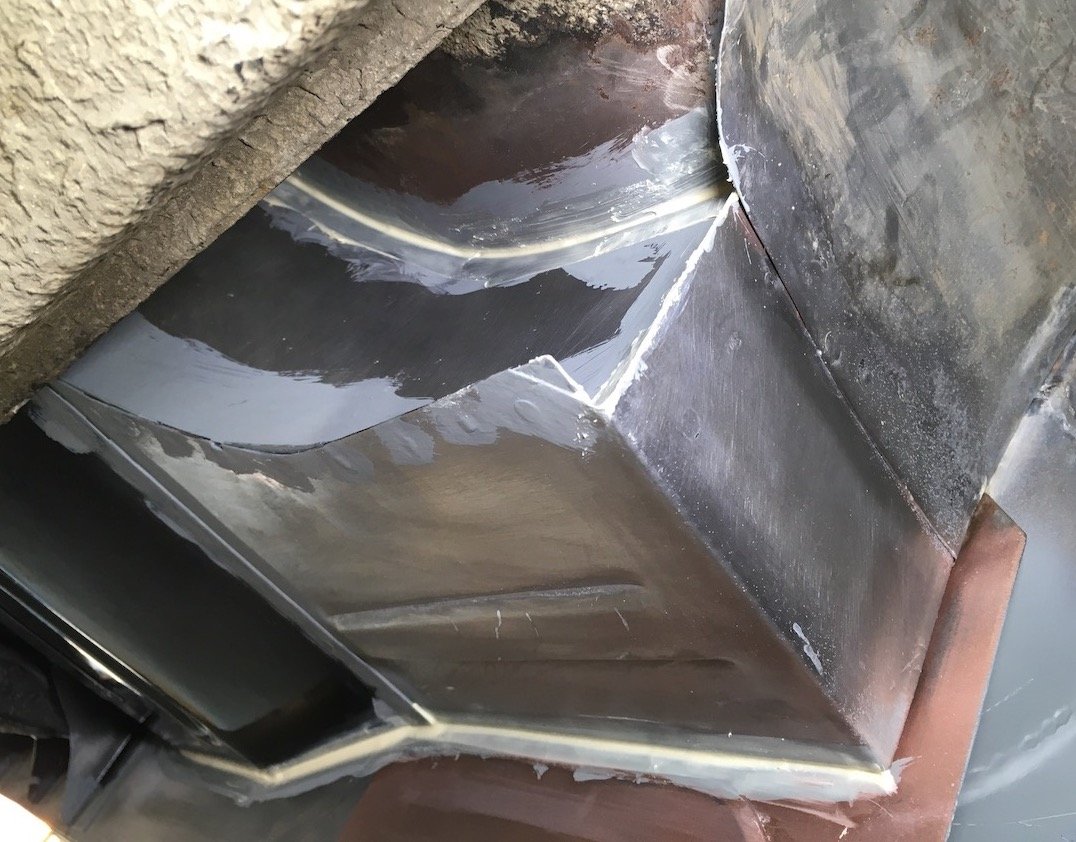
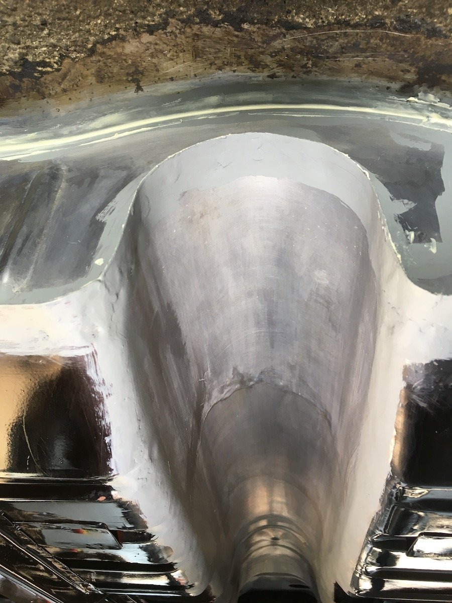
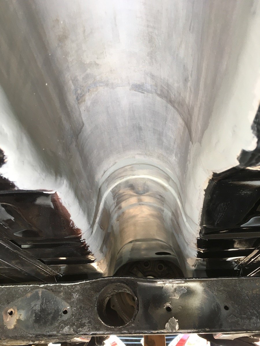
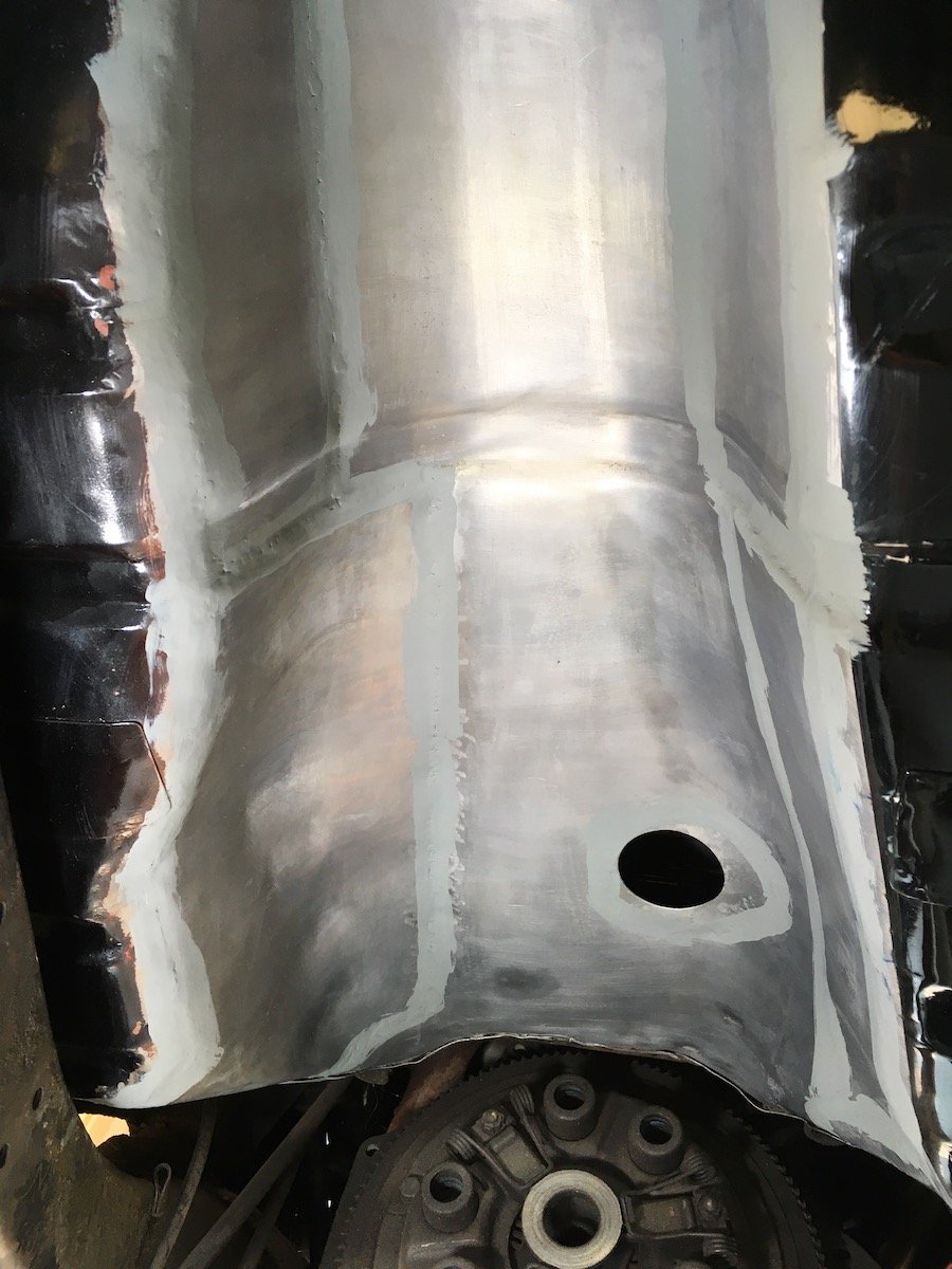
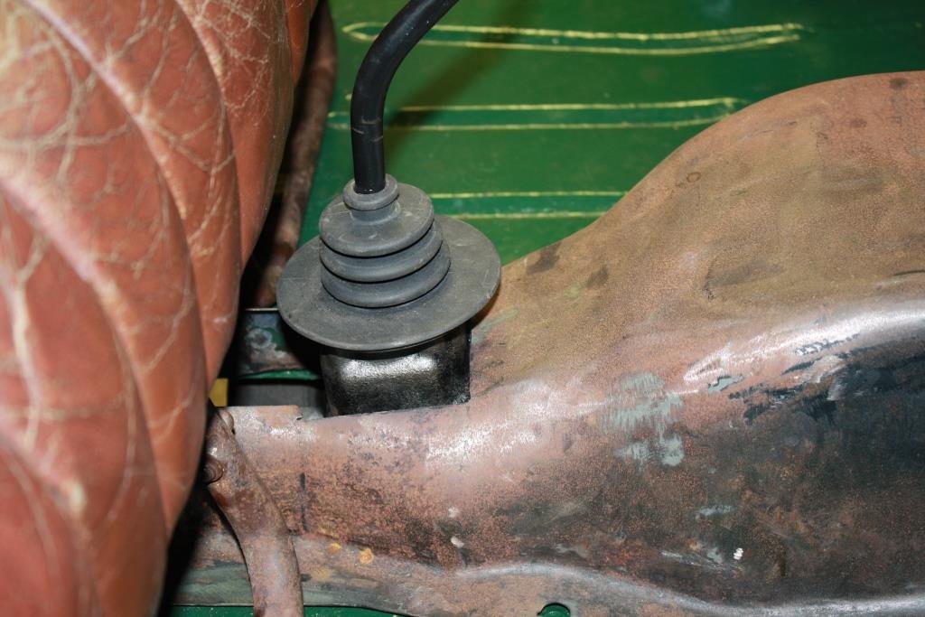
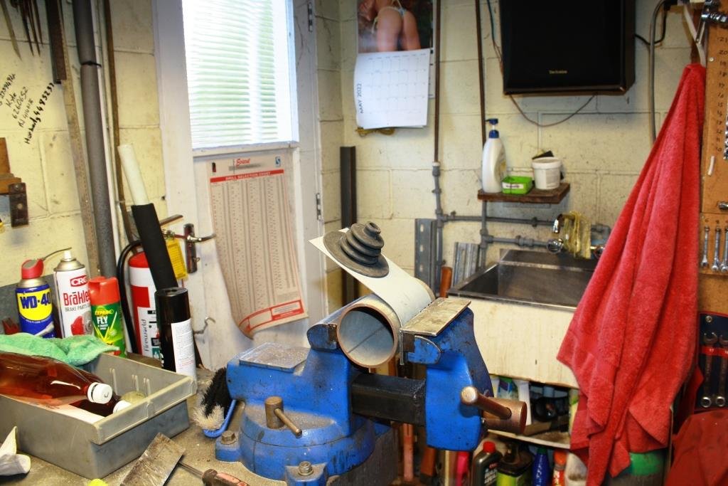
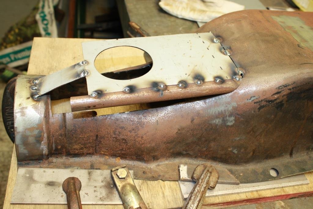
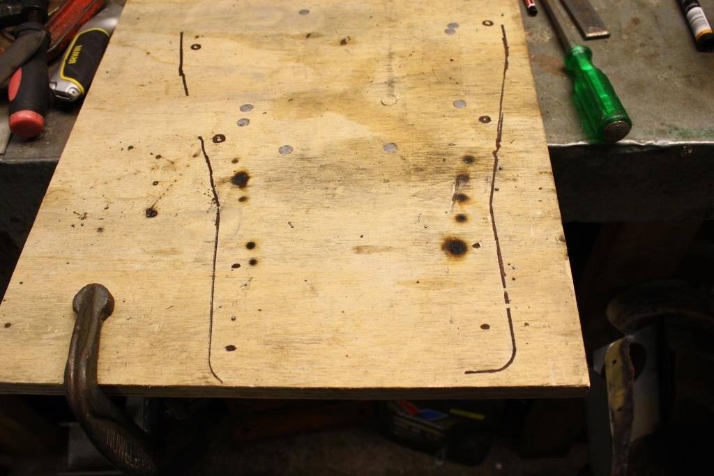
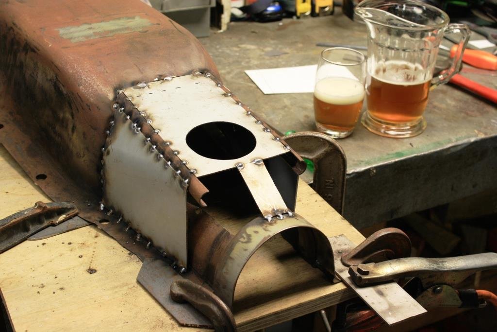
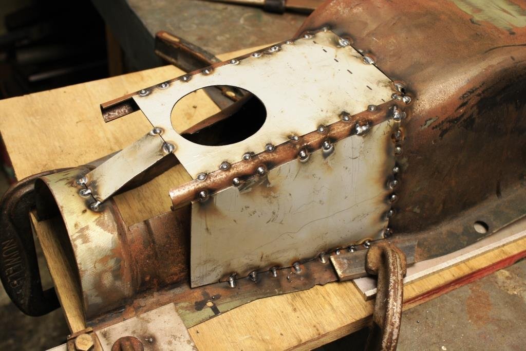
Time to get my butt into gear and finish the gearbox cover. I settled on using the MGB gear lever boot, it looks cool, English, and old-school. Made the call that the safest way to modify the "trans", (sorry, “non binary”) cover is to not remove any of the original metal until the new steel is welded in. I cut out a piece of plywood to act as a temporary spacer to give me clearance for the boot. I cut out a piece of 18 gauge Zintex with a hole in it to fit the boot. Bent it around an old piece of galv. water pipe….. ….and tacked it in place, lining it up with the plywood spacer. Clamped it all to a thick piece of ply and marked the outline to act at a reference point to keep things straight. With no sheet metal roller I decided to fabricate the curved corners I needed by slicing up some EWS tube. Tacked the corners on…….. And added some sheet metal. I did the same to the other side, followed by a quick check for clearance in the car……… With everything still straight and fitting well I clamped it back onto the ply in the pre-marked position. Time for “a cleansing ale”.
1 point
-
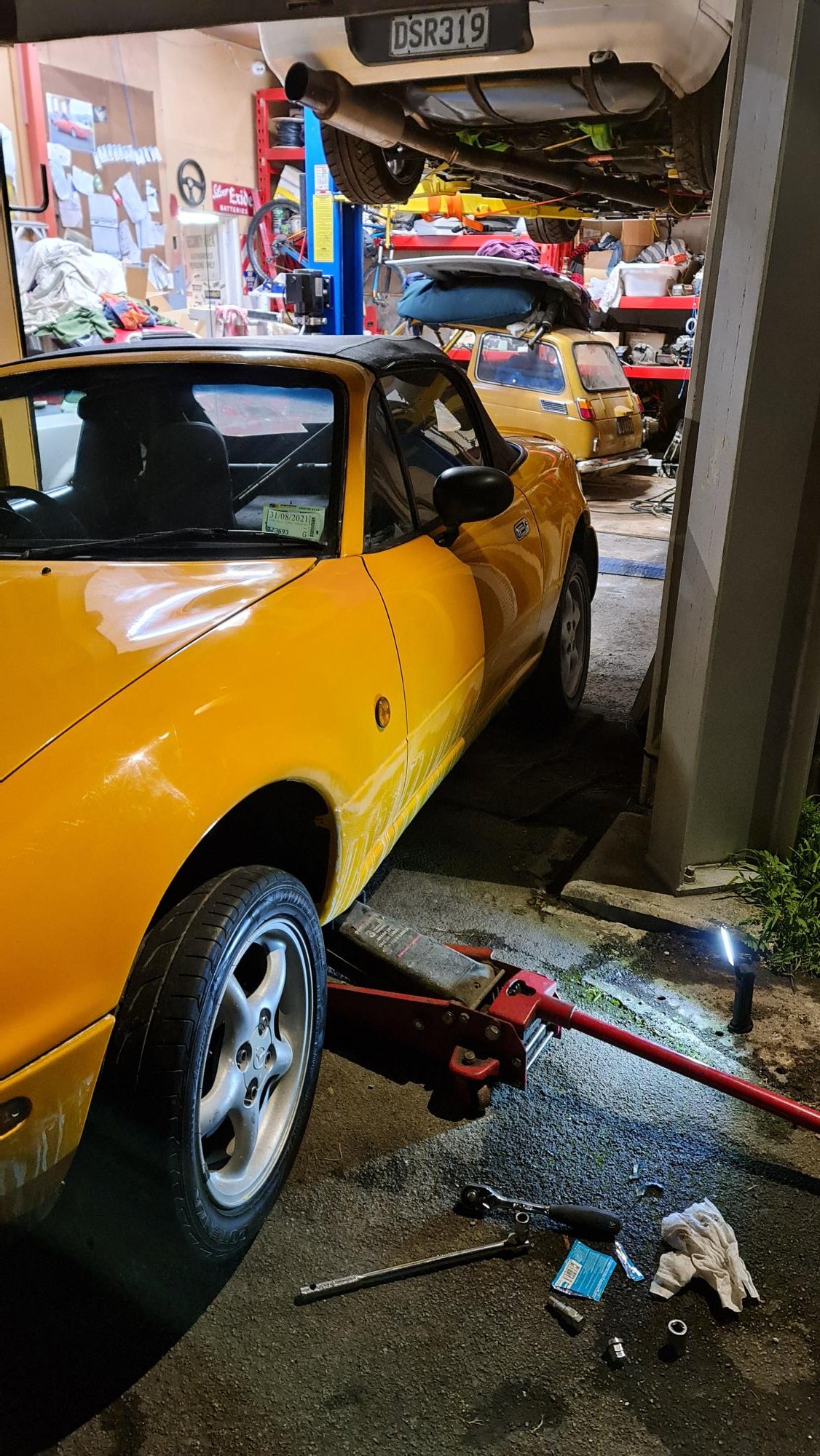
Drove it to work today and man it feels great, these are such fun cars to drive. Just makes you want to heel toe down shifts everywhere like an idiot. Also feels really good with the upgraded sway bars I put on just before starting the 'just fix that dent'. Smaller Momo steering wheel is much nicer than the stock one and a bit more leg room. A bit harder at slow speeds with the manual rack. EDIT: typos.1 point
-
Wof'd again after almost exactly 2 years, had to put a set of new rotors on it. It was 3 degrees C and late but I wanted to drive it again Not totally done with the paint, probably going to have to redo the clear coat on the bonnet. Not sure what happened but it wasn't fully hardened so the 1500 wet sand put scratches in it. Very annoying but it looks good if you don't look too closely lol.
1 point
-
I put a thing in a hole! It took a lot of convincing but got there in the end I was debating what to do with the water pump - but the bearing sounds a bit sketchy so it will be sent off for a rebuild.. all new engine and radiator - don't want it ruined.
1 point
-
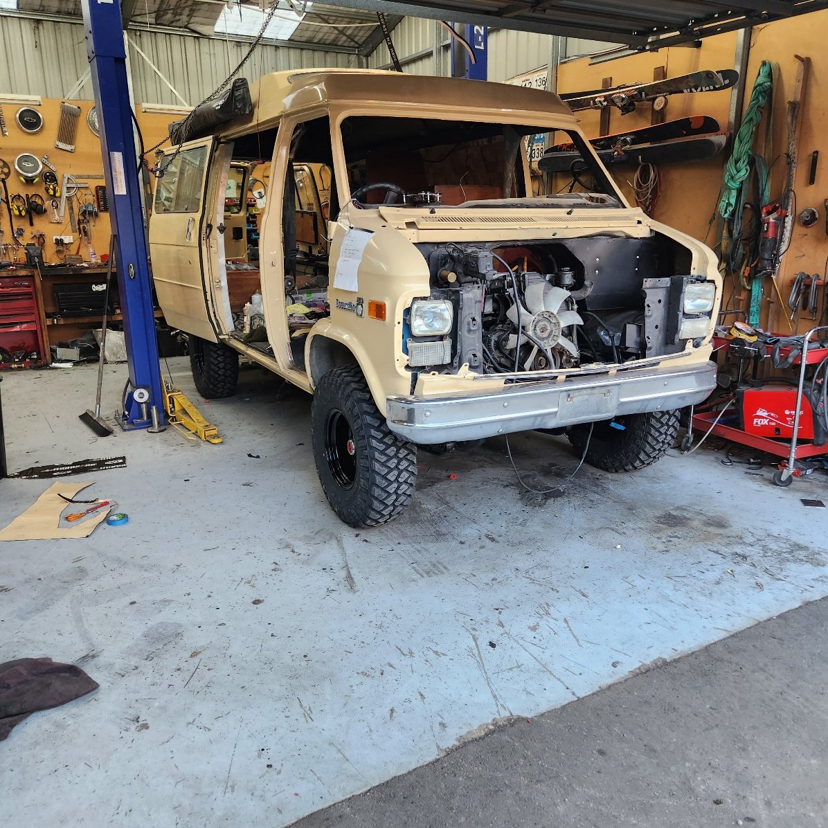
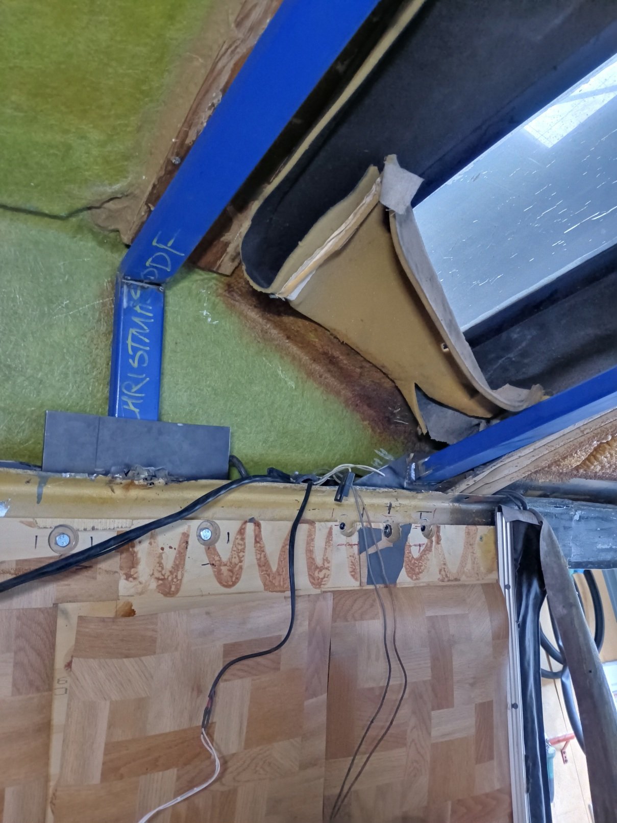
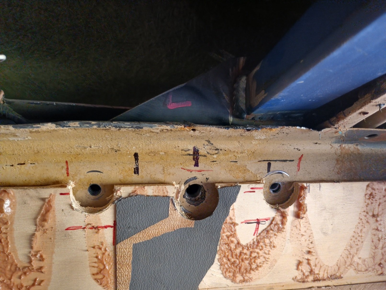
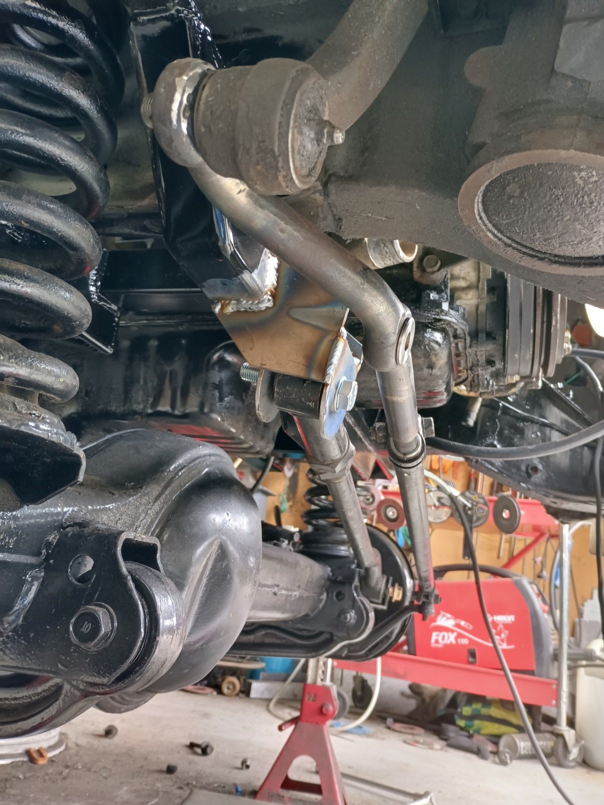
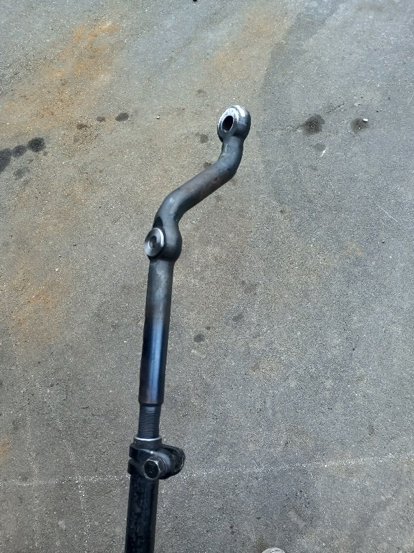
I got another good weekend in the shed, snow is shit and trails are muddy. I got front rails and engine cradle painted and engine in, no dramas, plenty of space around it I got the steering arm back from the machinist, he reshaped it for me and drilled out the centre taper, then made me a press fit bushing to take the metric ball joint on the steering damper, it works great and gives me plenty of space for the Panhard bar. I got the Panhard bar mounted and track set too and it sits good I stared farting around with the roof braces. The gist of it is when the glass roof extension went in they just hacked all the braces out so I need to reinstate the structure. I got one finished which braces the pillar belt mounts and mocked up the others, I need to speak to the certifier again tomorrow before I attach them for good, he's against welding them in so I'll bolt and glue them. Then I put the seat doublers in and read the info sheet again and realised they need to be riveted, rivets on the way. I also sold a 4L80e and transfer case to a fella from down south who rocked up in this weapon, home job turbo 5.3 with a big ol cam, looked and sounded like a shitload of fun
1 point
-
I tried getting the seat mounts and belts sorted this week but it got boring pretty quick, I've got the plates cut and a few in but need to rivet in the belt mounts. So I got to getting engine mounts sorted, the ply template gave me a rough idea of the sump clearance so chopped a bit out of the crossmember and sat it on place. Major issue is getting it in, the firewall sits midway along the engine, so I have to take 2 grabs with the crane, easy as long as the windscreen is out lol Once in it fits fine, I've given it 25mm of clearance between fan and radiator and it looks ok at the back for getting the trans in and out. Then i got straight into losing sleep over how to brace it all and mount engine and came up with this Which Im pretty happy with, I'll add the Panhard bar mount next then will get some paint in there and put motor in for good.
1 point
-
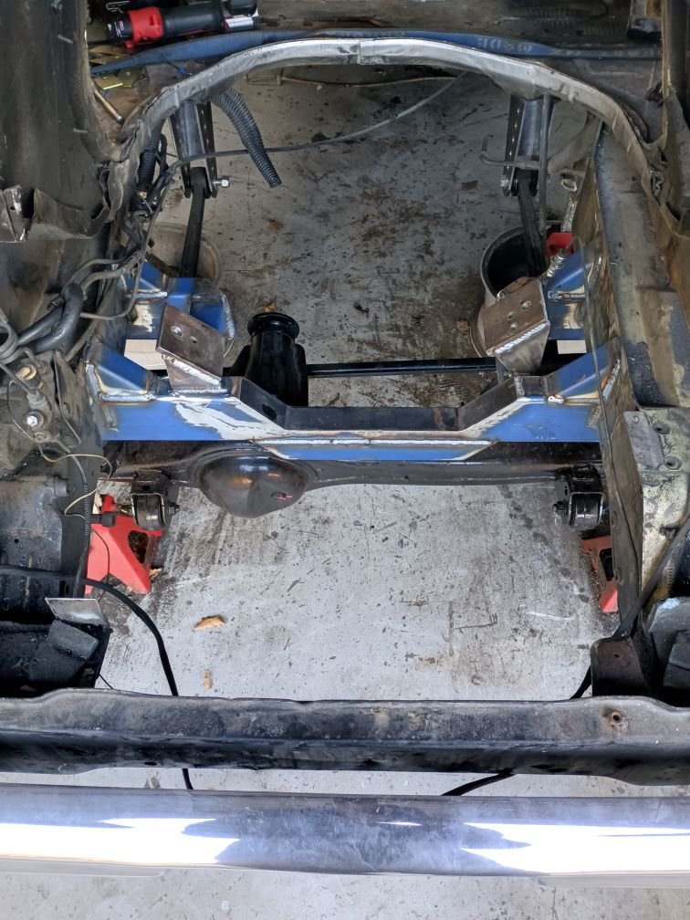
I haven't had much time in the shed this week, got a few jobs knocked off. My guy cut threads onto the steering crossover shaft to adapt the chev output rod to the Toyota crossshaft, it'll work but be tight with the Panhard bar so I need to.brain that some more, also need to make a bushing for the centre hole to take up the slop between the tapered bore and the mount stud on the steering damper to mount that. I got the back diff sitting in place,it's narrow but will work I flipped the shackles and ditched the blocks that were in there which gives me 5" of lift or so, I'm thinking I'll match the front to this, I want to add some airbags or gas riser shocks as well for driving when the boat is on and water tank full. I'll bolt it in tomorrow but won't weld the perches and shock moints in until engine and trans are in and I can set pinion angle I also got the front crossmember beams in. This was a bit of a job but I'm much happier with the spring hat strength now. Problems solved : - spring mounts stiffened - place to mount Panhard bar - ties front frame rails together again instead of just relying on core support - place for engine mounts to attach Problems created : - panhard bar sits at an odd angle with beams, needs brain - engine will sit too high to clear beams so I'll have to notch into them a ways then beef it up again after My welder was farting around a bit so have that a birthday and went back over a couple of beads too Next job is probably sort out the seat and belt mounts and frame up the roof for cert
1 point
-
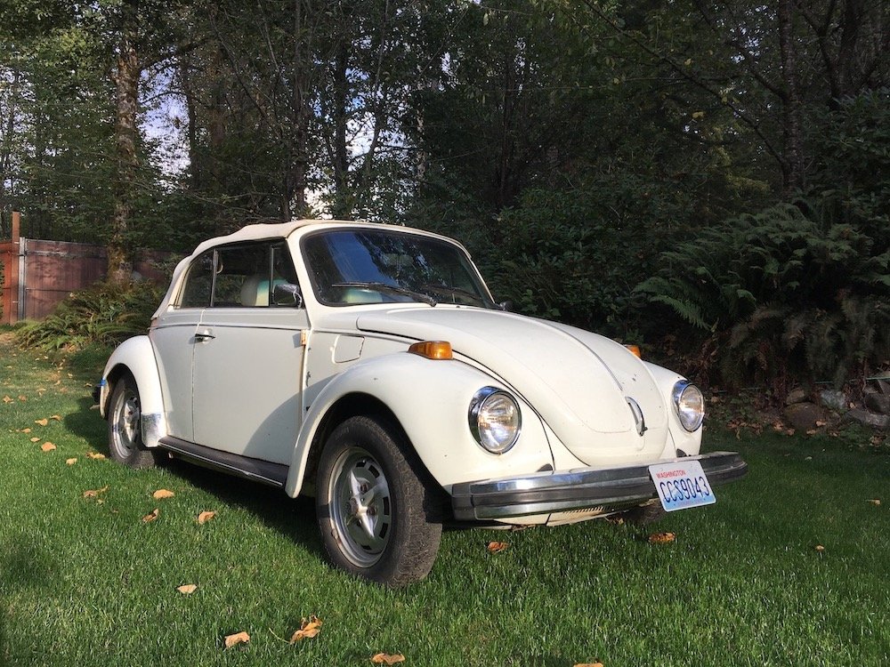
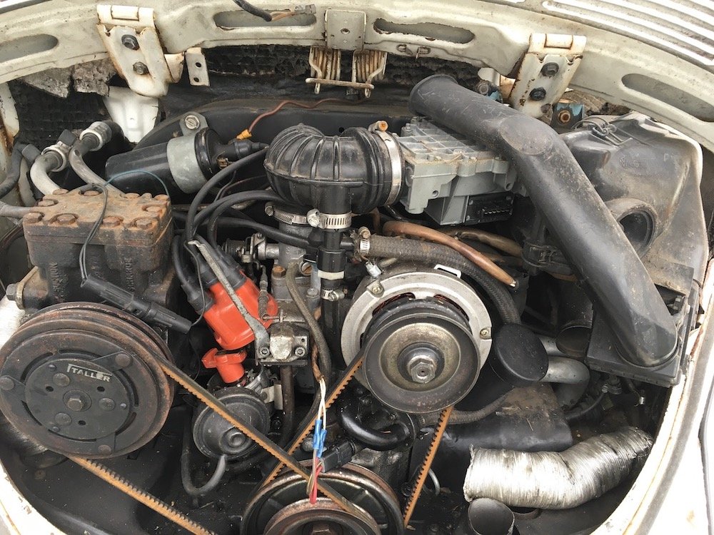
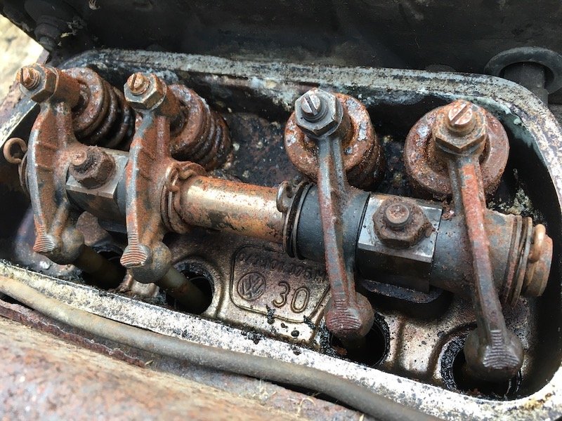
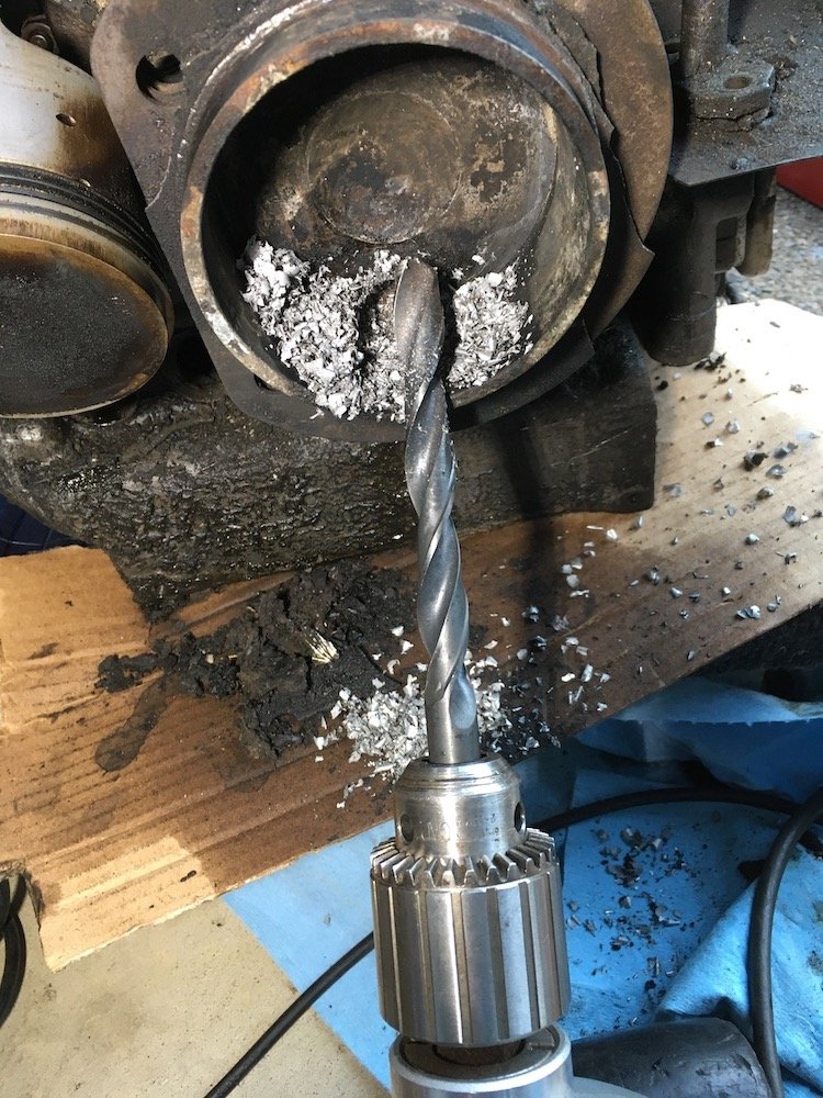
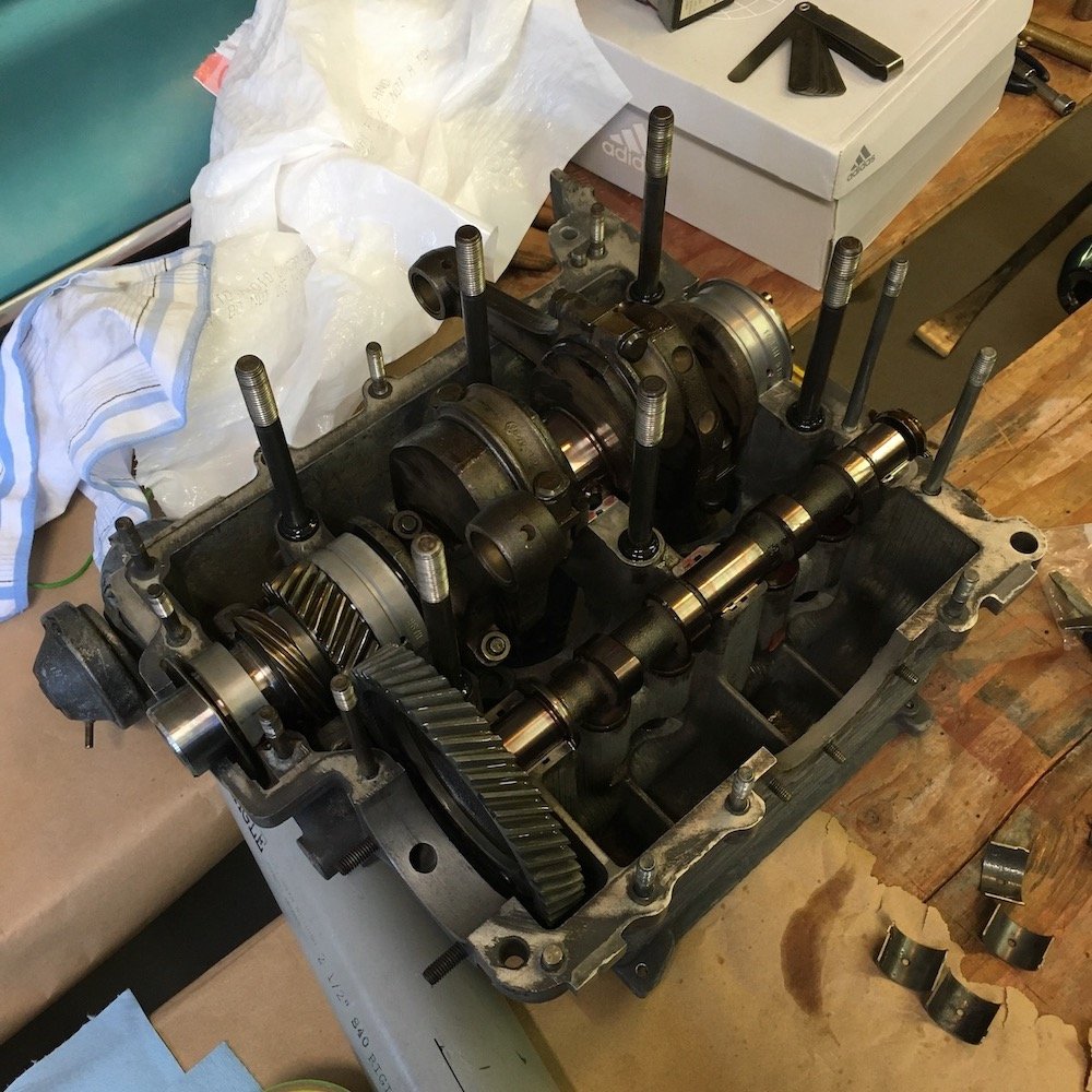
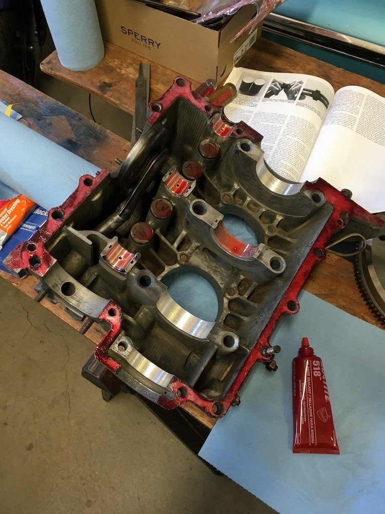
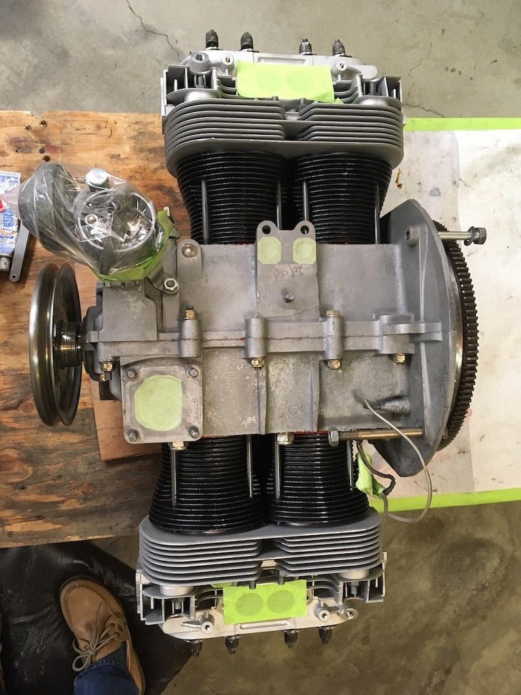
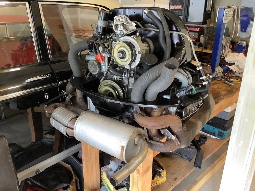
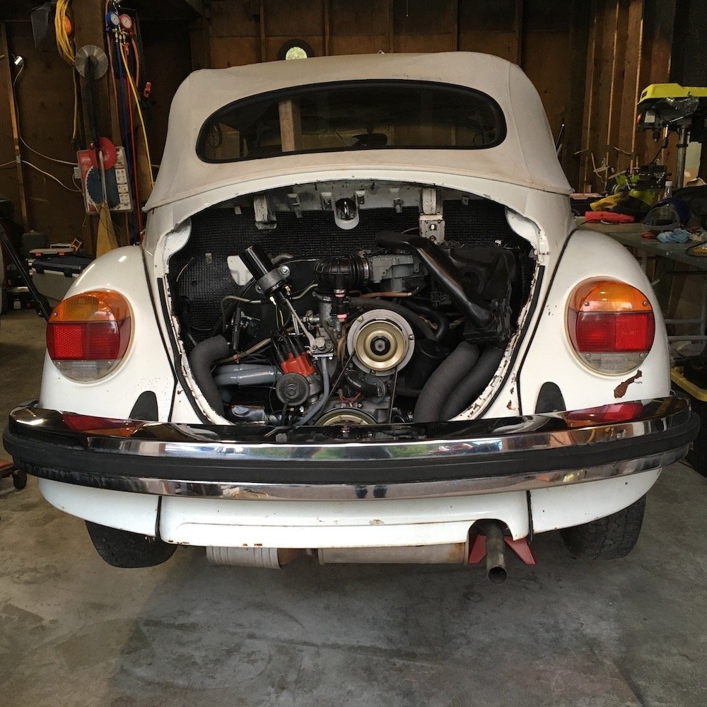
Building the 1961 Datsun 310 Bluebird - VW Distractions and painting the underside of the floors, tunnel and sills. I've been distracted by my other project for several months - getting the VW Beetle project that I inherited from my sister up and running. Now, over the last week or. so I've jumped back on the Bluebird project in order to complete painting the underside of the metalwork before the wet and cold weather sets in. Our Pacific Northwest "Endless Summer" that we have enjoyed since June flips over to the normal cool and wet fall in just a few more days. Yes, the frame rails are still filthy. Just thankful they aren't rusted out. Some day they will be cleaned up. Finished on the last warm day this week. I didn't want to be painting the underside of anything in the cold and have the paint drip down on me while laying on my back on the low boy creeper. Showing some photos below of the VW project distraction before moving on to more detailed posts of the painting job preparation and completion. Mainly it's a seized engine teardown and reassembly with new pistons, cylinders and heads. Engine bottom end was good except I elected to have the mains align bored. Plus, I'm still fixing numerous other problems due to corroded electrical connections throughout the VW chassis, especially the grounds. Hope nobody minds the momentary VW diversion. As the '79 VW was found, it included a huge AC compressor which will be discarded due to broken casting and excessive weight! Car had been sitting outside for years, fully exposed to the rain falling through the air inlet vents directly onto cylinder no. 4 spark plug hole, unfortunately it had been stripped out and the plug was left out resulting in a cylinder filled with water. A bit rusty it was. Destructive teardown to separate rust welded no. 4 piston/cylinder. Cylinders and pistons were to be tossed out anyways. Reassembly of bottom end begins. Polished crank, main bearing align bore, new bearing shells and reused all the rest. Had the air cooling tins satin black powder coated. It lives! Yes, looking through the rear glass, that's a 2 by 4 board holding the rotted top structure up.
1 point
-
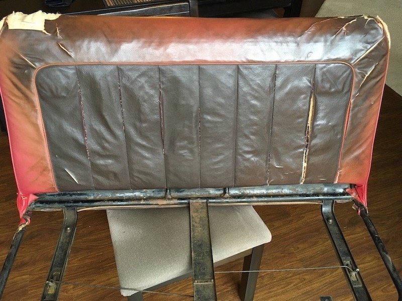
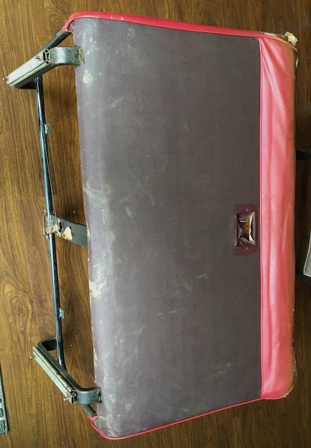
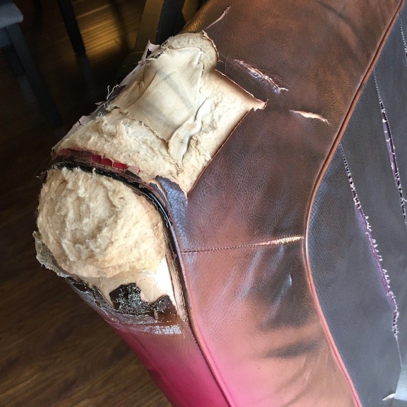
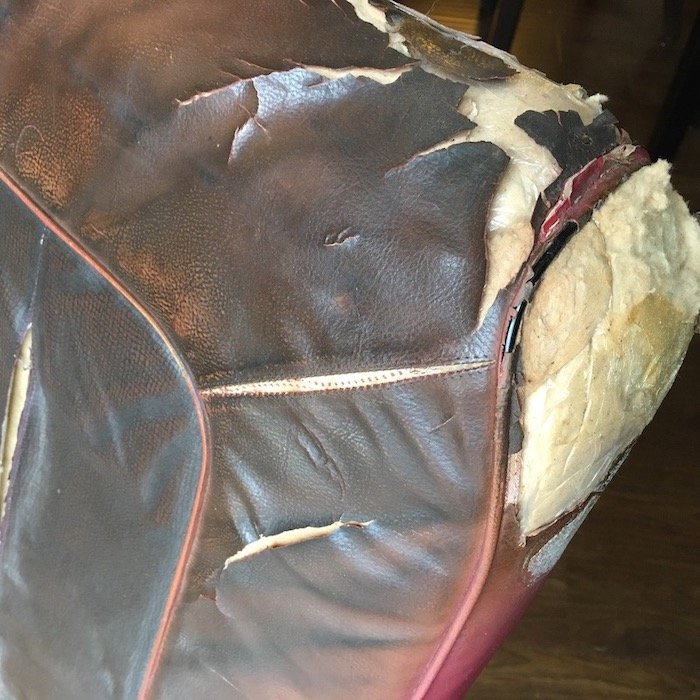
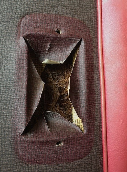
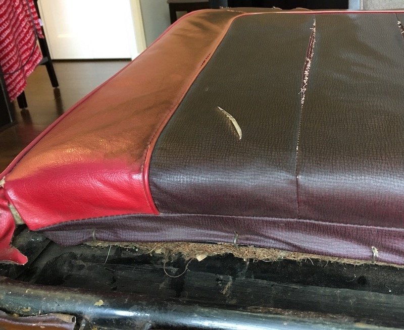
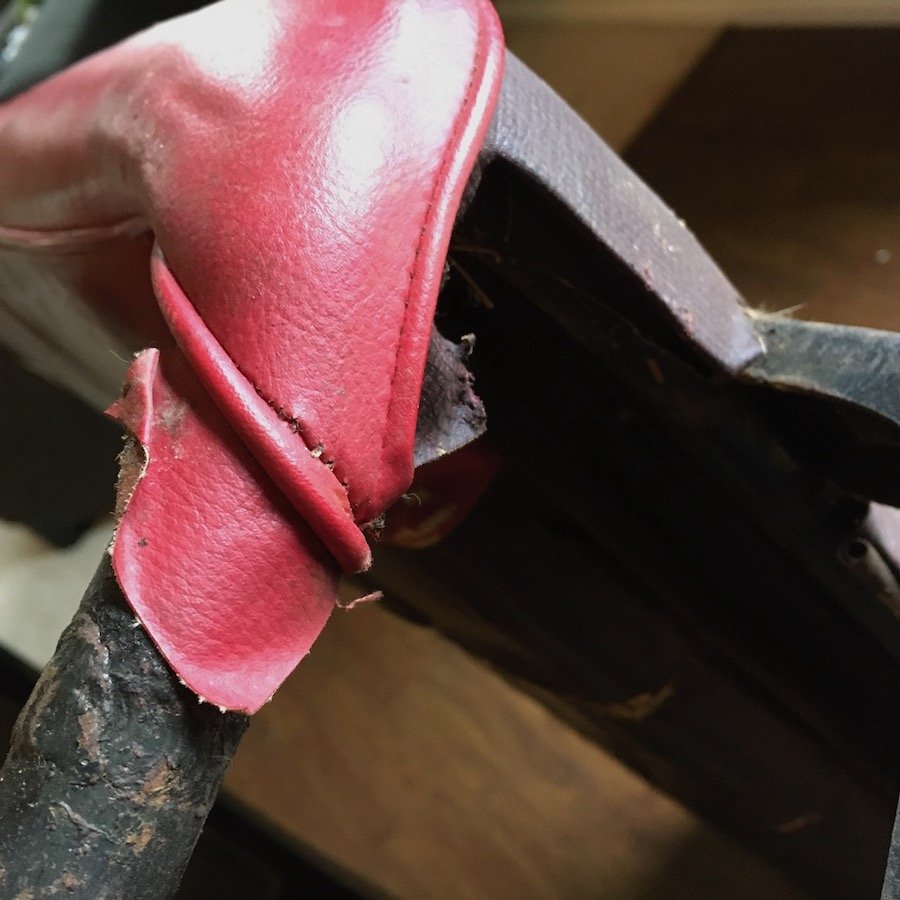
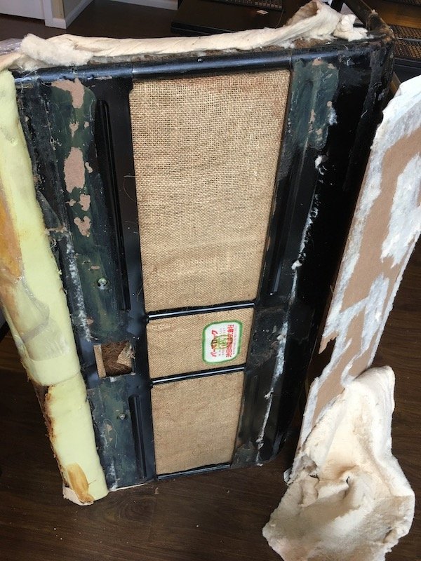
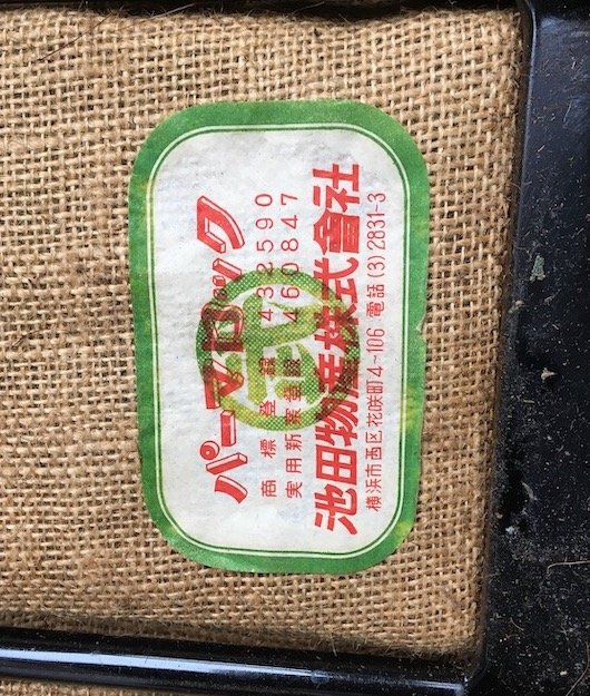
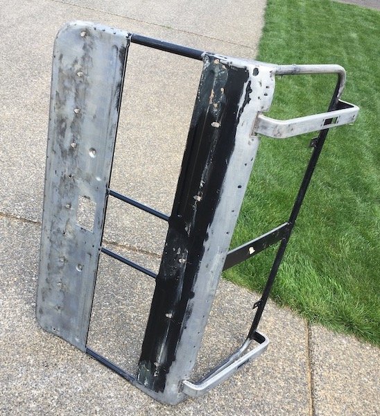
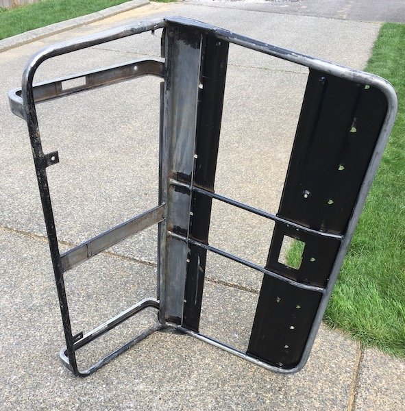
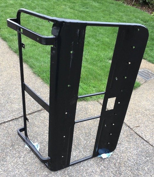
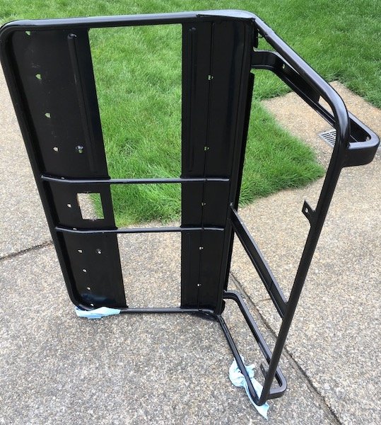
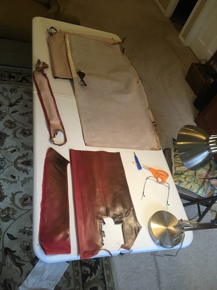
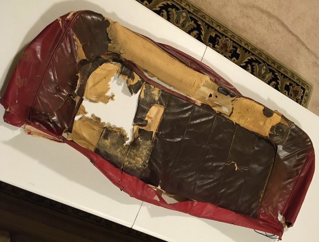
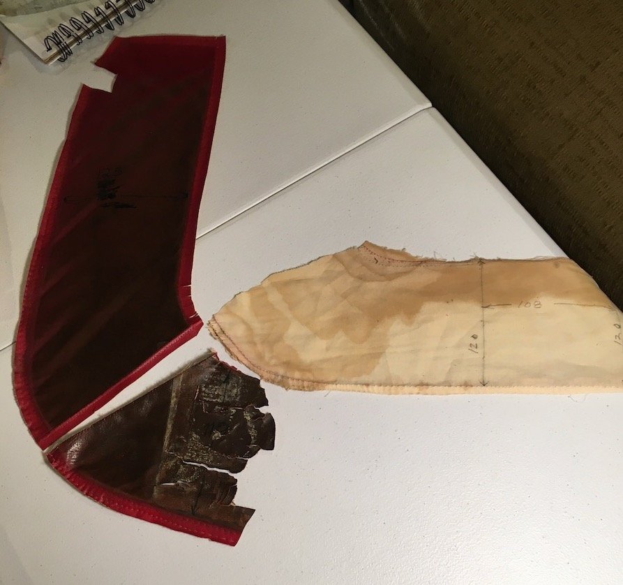
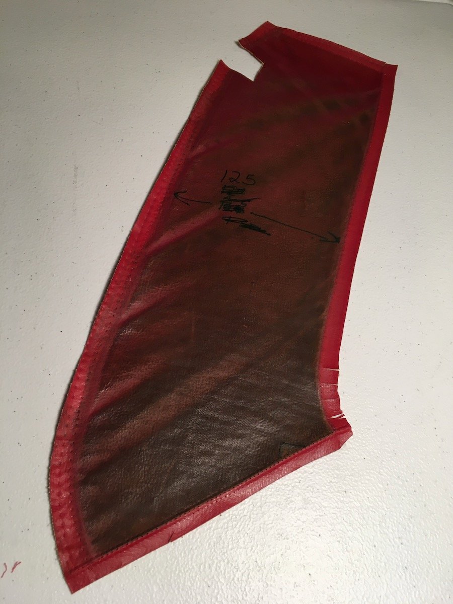
Building the 1961 Datsun 310 Bluebird - Upholstery Trimming Continued - Front Seat Backrest - Part 1. Though it has been several months since my last post, I actually have been hard at work on the project. A fair amount of progress has been made on the interior soft trim. The following is some of what has happened since then. Front Seat frame and backrest: Backrest separated from from frame Frame repaired and painted Insides of coconut fibre filled backrest reconstructed and padded Vinyl and pleated insert cloth seat cover patterns made Prototype and final seat cover assembled Seat cover installed All four door cards are built as new using the original materials as patterns. Armrests are rebuilt with new red vinyl. Miscellaneous trim over the inner rear wheel well arches made with new vinyl. Rear seat backrest coil spring frame assembly blasted and coated in black by Seattle Powder Coat. I’ll start with this post on the front seat backrest teardown and frame reconditioning/repairs. More posts to follow shortly once I downsize and edit a huge bunch of photos. A historical photo from several years ago (2017) showing the cheap orange-red and black top cover thrown over the original factory upholstery. Basically, an oversized sock roped down to the bottom of the frame with thick thread. It was probably installed when the car was about 10 years old (1971?) is my best guess. I tore it off several months ago and will trash it. Frontal view of original backrest cover that was hiding underneath Rear view Badly damaged corners All the material was sunlight faded except underneath the ash tray bezel. I pondered the wisdom and fire safety possibilities of the flammable coconut fibers directly in front of an ash tray. Some of the attachment details to the frame recorded so I can assemble it the same So then I undid these and other attachments and pulled the cover off. The outer layer of coconut fibers were somewhat unstable and messy as it would disintegrate simply by light touch I removed the cotton batting off the back Masonite hardboard and levered it away from the glue to the frame. This then revealed the burlap backing and supplier decal underneath. The hardboard was salvaged and reused. I salvaged the burlap and supplier decal as well. Then two small screws on either side of the ash tray pocket were removed to release the coil spring and coconut fibre assembly from the main frame. Cleaned the frame of dirt, rust and glue residue and repainted the bare steel areas. I failed to photograph the damage and repair where the sheet metal under curled bottom edge was broken due to seat travel extension modifications that pushed it hard against the driveshaft tunnel. Sorry, but it was a simple crack weld and grind back smooth fix. Cleaned Painted Hopefully, more posts soon, to show reverse engineered patterns and other such completed work as noted above Discussion & Build:https://oldschool.co.nz/index.php?/topic/60267-marts-pl310-61-datsun-bluebird-sedan/https://oldschool.co.nz/index.php?/topic/60264-marts-pl310-61-datsun-bluebird-sedan/
1 point
-
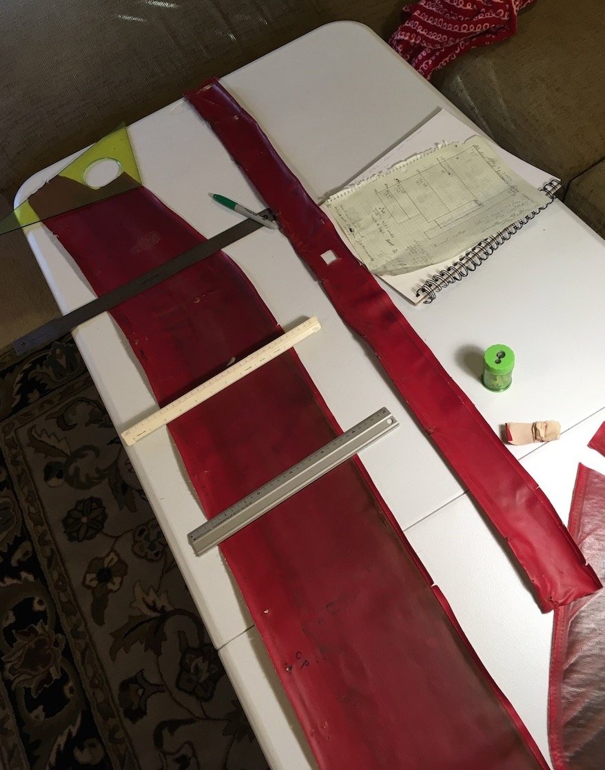
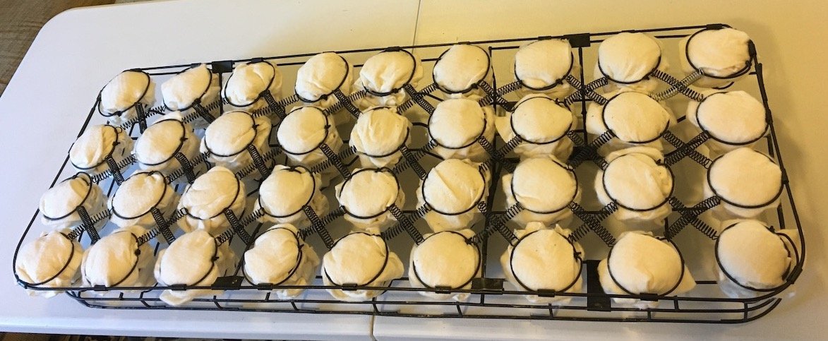
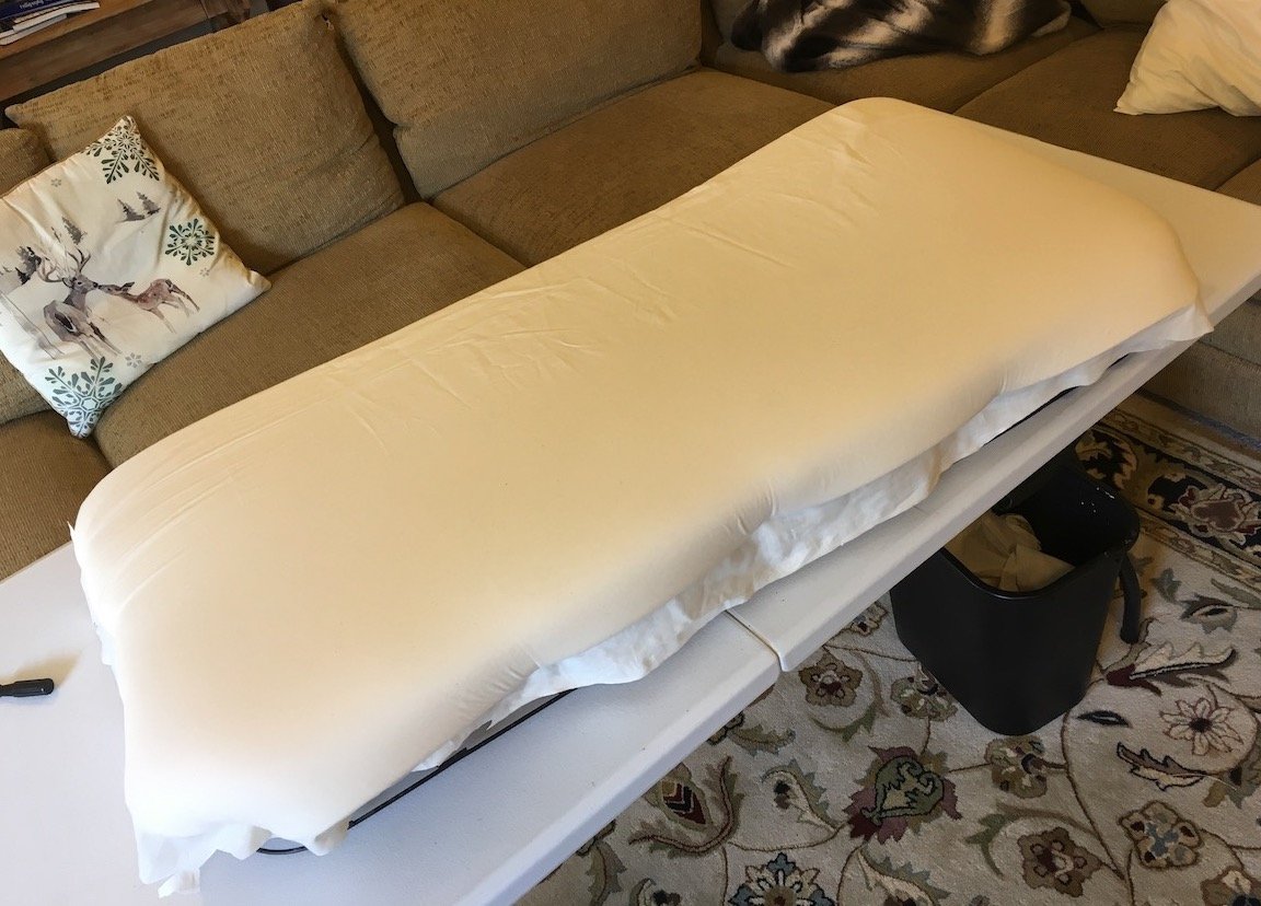
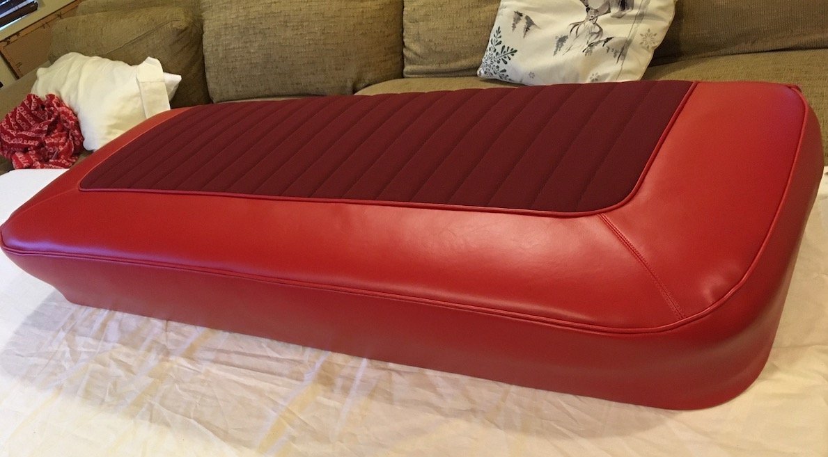
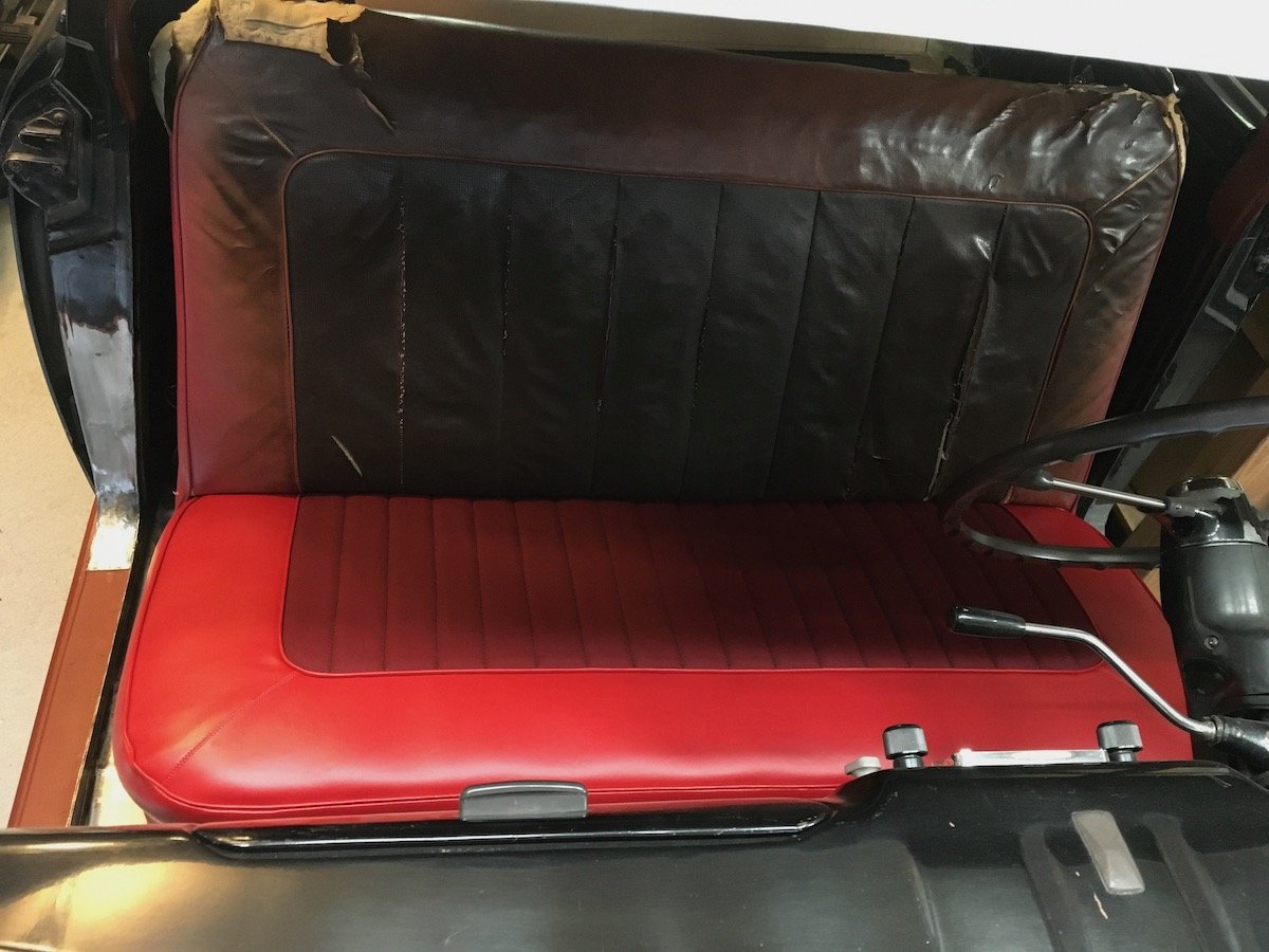
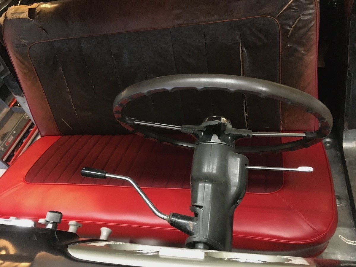
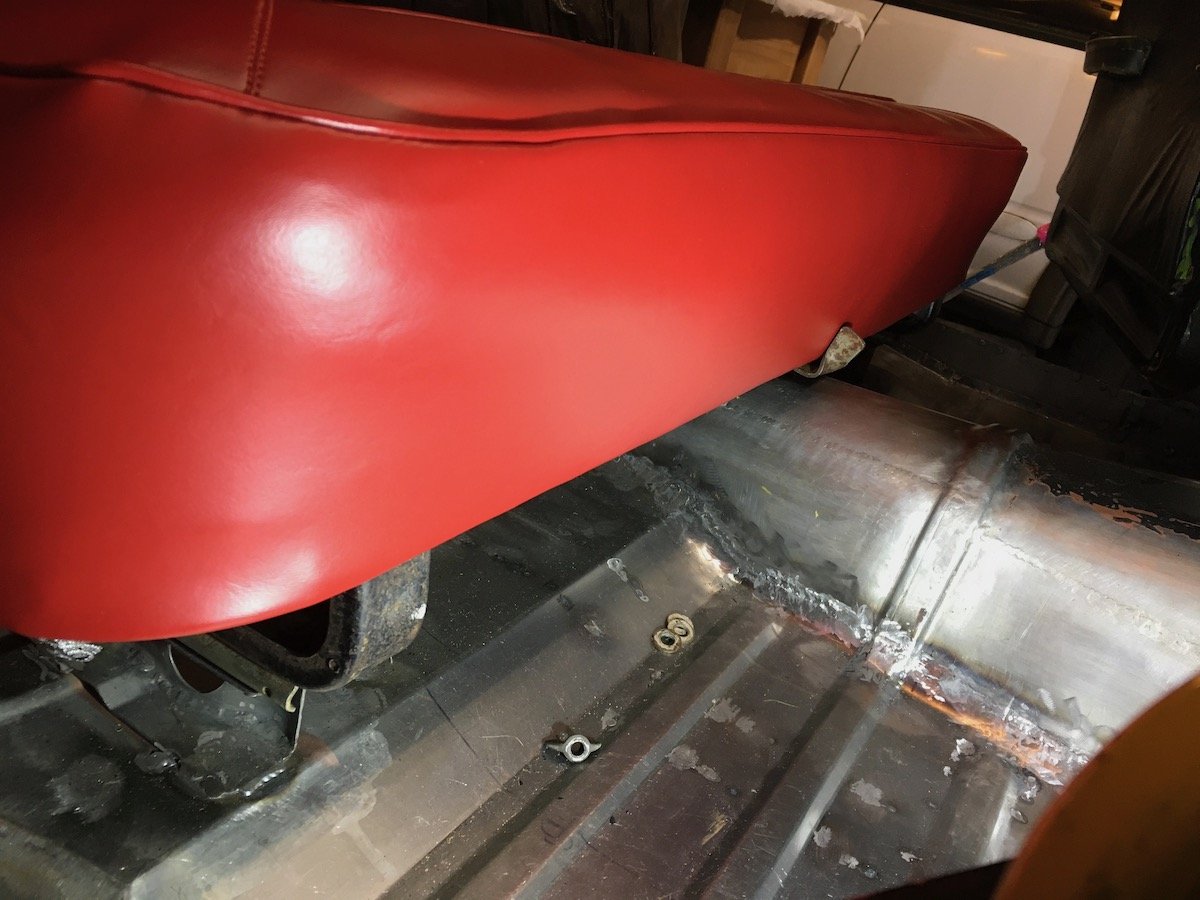
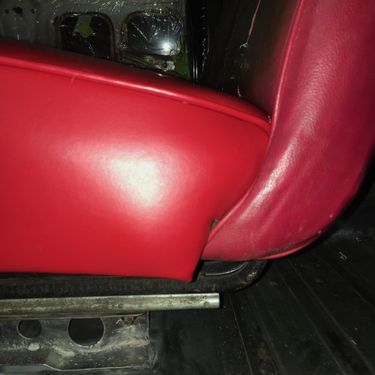
Building the 1961 Datsun 310 Bluebird - Front Seat Cushion Build. I completed the front seat cushion assembly and did a fit check today. The backrests for both seats still remains to be worked. Some photos of the front seat build follow. About all I had to go on when making vinyl patterns out of the existing front seat cover. Not good. Went ahead anyway and it turned out nice! The pleated cloth insert section was made identical in overall width (about 850 mm) to the rear seat but shorter in fore-aft direction. Seems the rear seat offers a bit more room than the front. So I salvaged what I could and trimmed out some patterns for direct use on the new vinyl. The discoloration from UV exposure is extreme! I had to iron the old bits to get them to lay flat. I prepared the seat frame with a clean up and touch of rattle can black. I bolstered the very soft coil springs by stuffing cotton batting into each one. Looks like a bunch of biscuit dough ready to bake! Added the burlap and one inch thick foam. This time, I added a thin layer of muslin over the seat foam and hog ringed it in few places to help bend the edges over. The muslin cloth reduced the friction when dragging the seat cover on. That helped a lot. Previously, it was a real struggle and fight to slide the rear seat cover on as the underlying half inch sewfoam of the cover dragged horribly against the seat foam. I still fought getting the front seat cover on, as the corners were quite tight by design, but not nearly as much as for the rear cover without the muslin layer. The finished front seat cushion. Not perfect, but serviceable and obviously much better than the tattered original. Just the outer corner welting turned out a bit wavy, otherwise ok. Hog ringed underside. There are two thick steel listing rods embedded in the vinyl loop that the hog ring rings grab onto and attach to the seat frame. One wraps around the front and sides while the other goes across the rear edge dipping in a bit at the seat center. Some installed views for fit check purposes. Fit check was near perfect, no real problems. Shows quite a contrast with the old scorched backrest upper! I sat on the seat and bounced around a bit. Firmness was just right with the cotton stuffed coil springs. Nice to sit behind the wheel again after several years! Front face view. Clearance with the seat adjuster lever is about 2 mm. Intersection view at the backrest bottom. Nests together nicely!
1 point
-
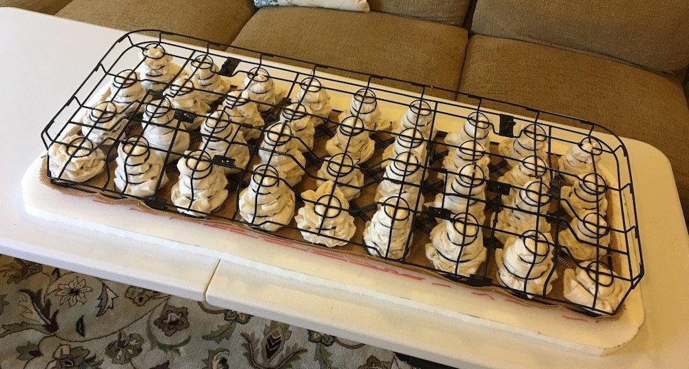
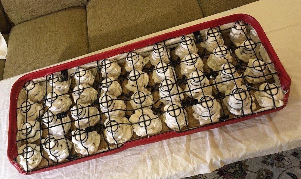
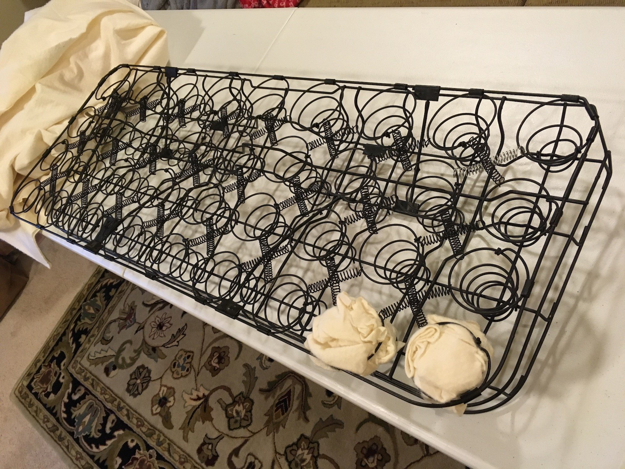
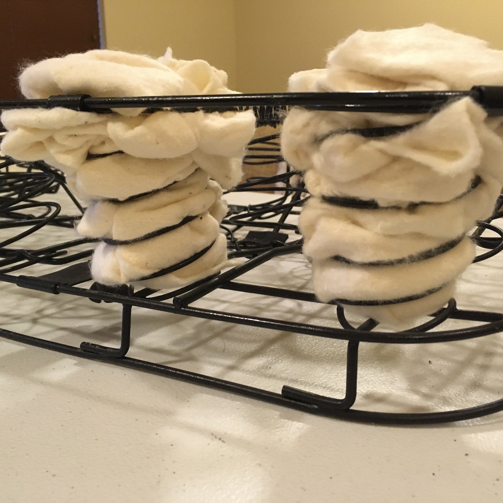
Building the 1961 Datsun 310 Bluebird - Front Seat Springs. Soliciting some thoughts on seat springs. I'm working on the front seat and am now at the point of assembling my newly fashioned homemade front seat cover onto the lower seat frame and springs. The original 60 year old springs are very worn out and super soft, providing only enough support for maybe a small cat. Identical replacement springs are not available, all generic upholstery springs I've found are way too large in diameter and length. If any human sits on this after the burlap, foam topping and seat cover is installed, they will find their bottom bottomed out, so to speak. I expect the new seat cover and other materials to be quickly damaged as a result. So I'm stuffing the 36 front seat coils with cotton batting to bolster them a bit. The photos provide a glimpse of the stuffed coil plan. An idea snatched from a youtube video. Seems reasonable. Anybody else done this sort of odd seat spring repair? Does it work? Any better ideas? If so, please comment on the project discussion page.
1 point
-
1 point
-
1 point


.jpeg.2ebc77c414805ebe0aab9deba31453a9.jpeg)
.jpeg.bd4fb6cb86793ced4dcedd293fc68fd5.jpeg)
.jpeg.cb7f39a86d54bcd96f7e3972694e9b62.jpeg)

.jpeg.7587da45208e8731bdaf622fb8ded615.jpeg)

.jpg.0c73f76da09f24423833198f712f4cbd.jpg)


.jpg.4273c6700fd4a62ae30a21ce3defd3d2.jpg)


.jpeg.852e6a20efbcbbef2f63cdbb0195f764.jpeg)
This leaderboard is set to Auckland/GMT+12:00