
Leaderboard


Popular Content
Showing content with the highest reputation on 27/02/20 in all areas
-
Cool kids wear fresh Lids14 points
-
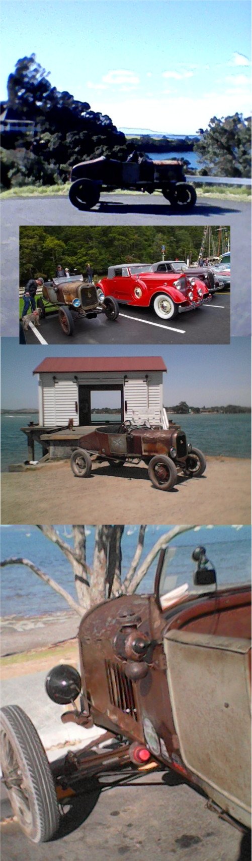
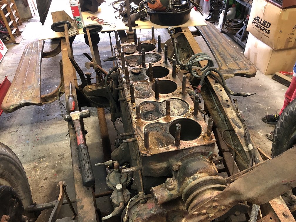
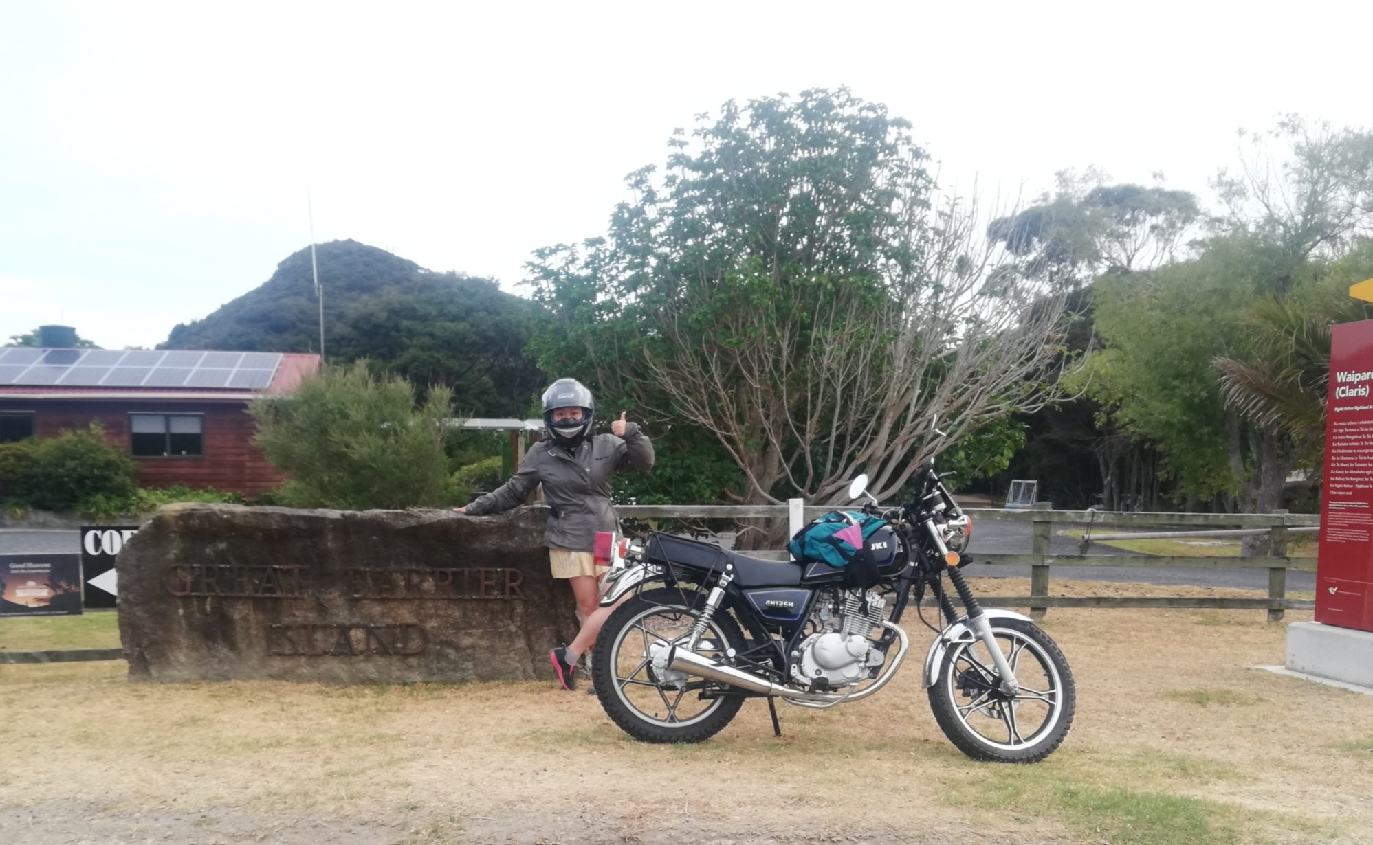
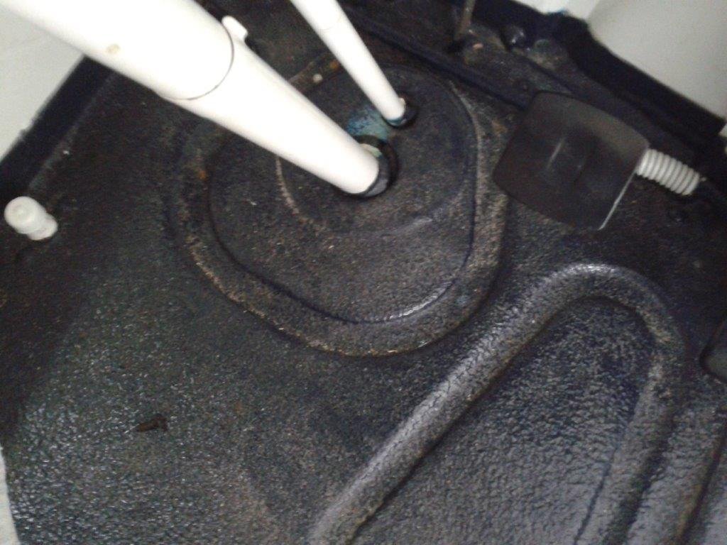
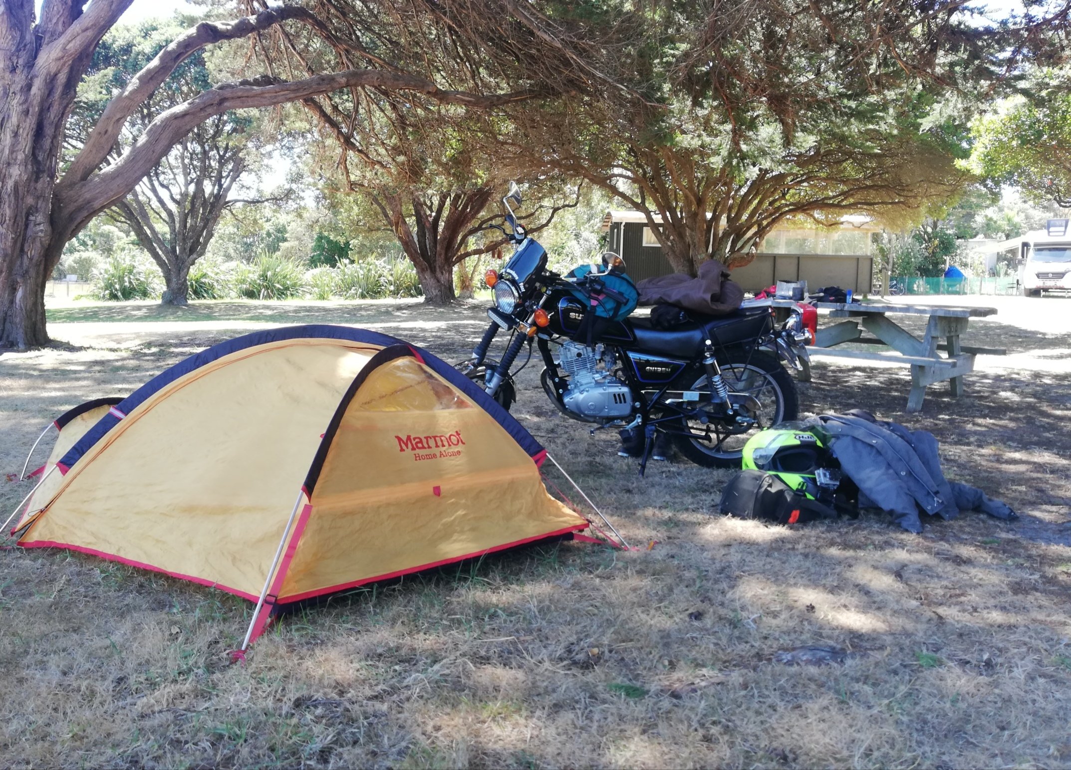
Most of the old pictures died but i'll see what i can do to replace them. So i learned you can use a pocket knife to carve totara & chewing gum to make a makeshift oil plug, or a frost plug. Just some pictures of some travels.
 13 points
 -
Made a start modifying the 4-link mounts. As you can see they originally hang quite a bit lower than the sill. New mount all welded up. Should be heaps strong enough! Cleaned up a bit. 17mm socket just fits through the channel to tighten/loosen the bolt. Might swap to Allen head screws, as the paint/underseal mightn't leave enough clearance. The lower arm is nice and level now. Next was to do the upper arm mounts. This is it all done coming through the floor under the rear seat. The seat just doesn't fit, but should be an easy fix by bending one of the wire spring things a little. Top arm angle looking much better. The arms should intersect pretty close to where I guessed the instant centre of the car will be. Just have the other side upper mount to finish off. Sent a bunch of stuff of to be zinc plated. Some didn't turn out as shiny as I'd liked, but not all of it's that visible and I think I'll get the engine and gearbox mounts powder coated any way.11 points
-
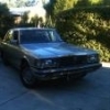
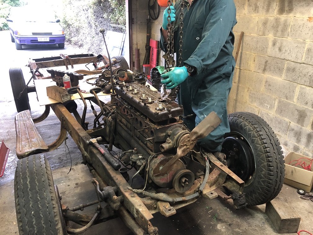
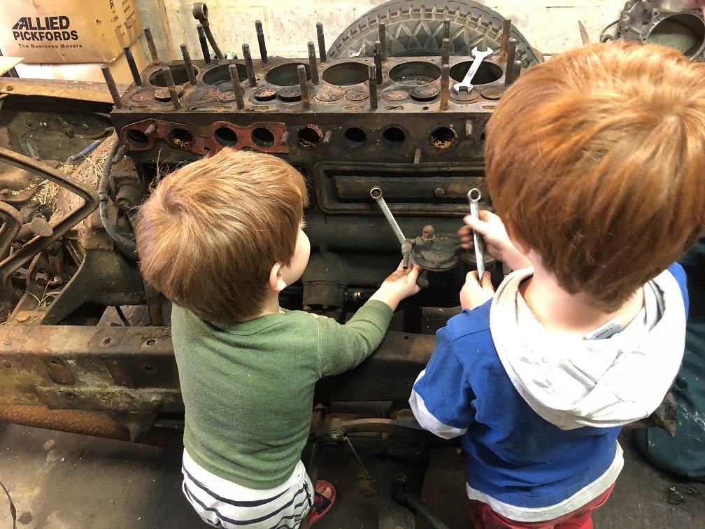
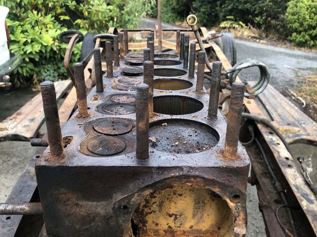
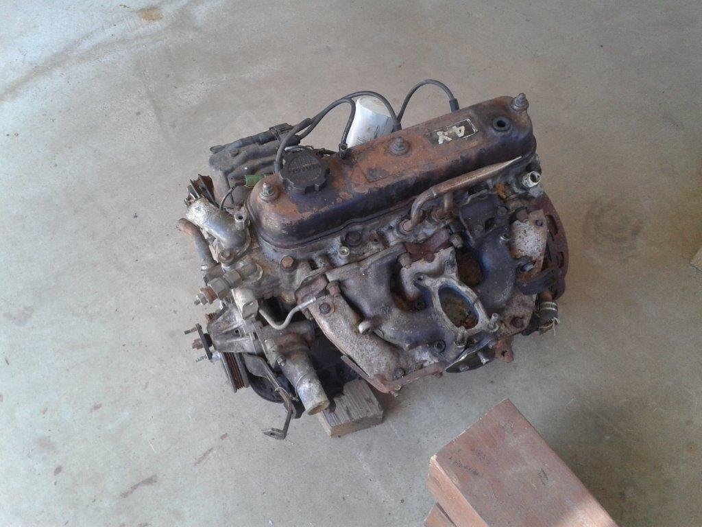
We've set ourselves the goal of having this run under it's own steam before Christmas, only time will tell if that's realistic. 21 head studs and 35 years of rain, not a great combo. We had the engine crane hooked to the head almost lifting the front wheels off the ground before she shifted! Minimal bore damage from what I can see. The valves aren't pretty, but what is on this so far. We'll keep tearing this down and drop the bare block to the reconditioners for closer inspection and start a parts hunt.
7 points
-
All very painless. Lots of rust converter poured down the pillars and copper sprays for days Soz I remembered about pictures as I finished with the black zinc Fluked the rail, even the chrome clips on6 points
-
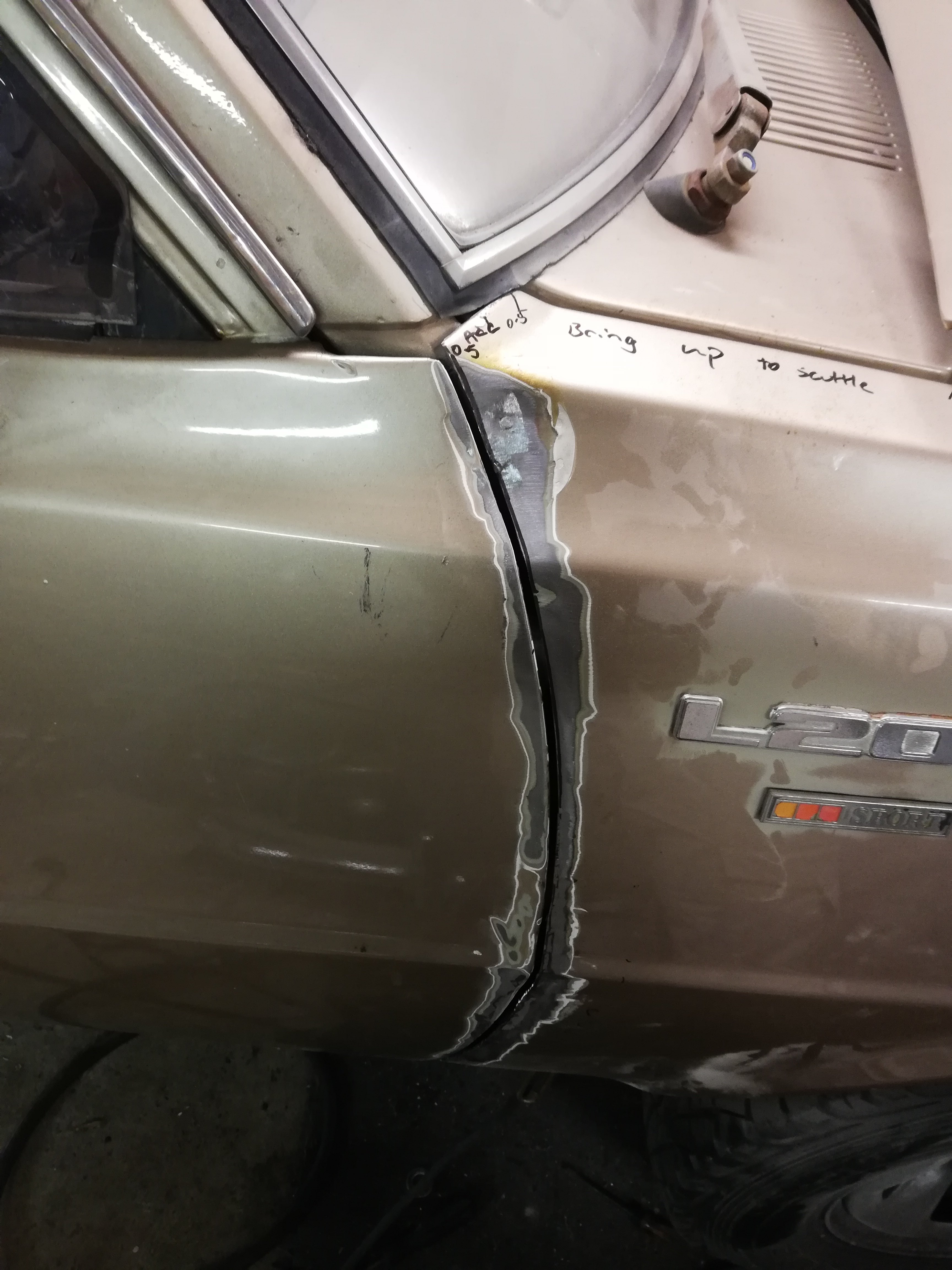
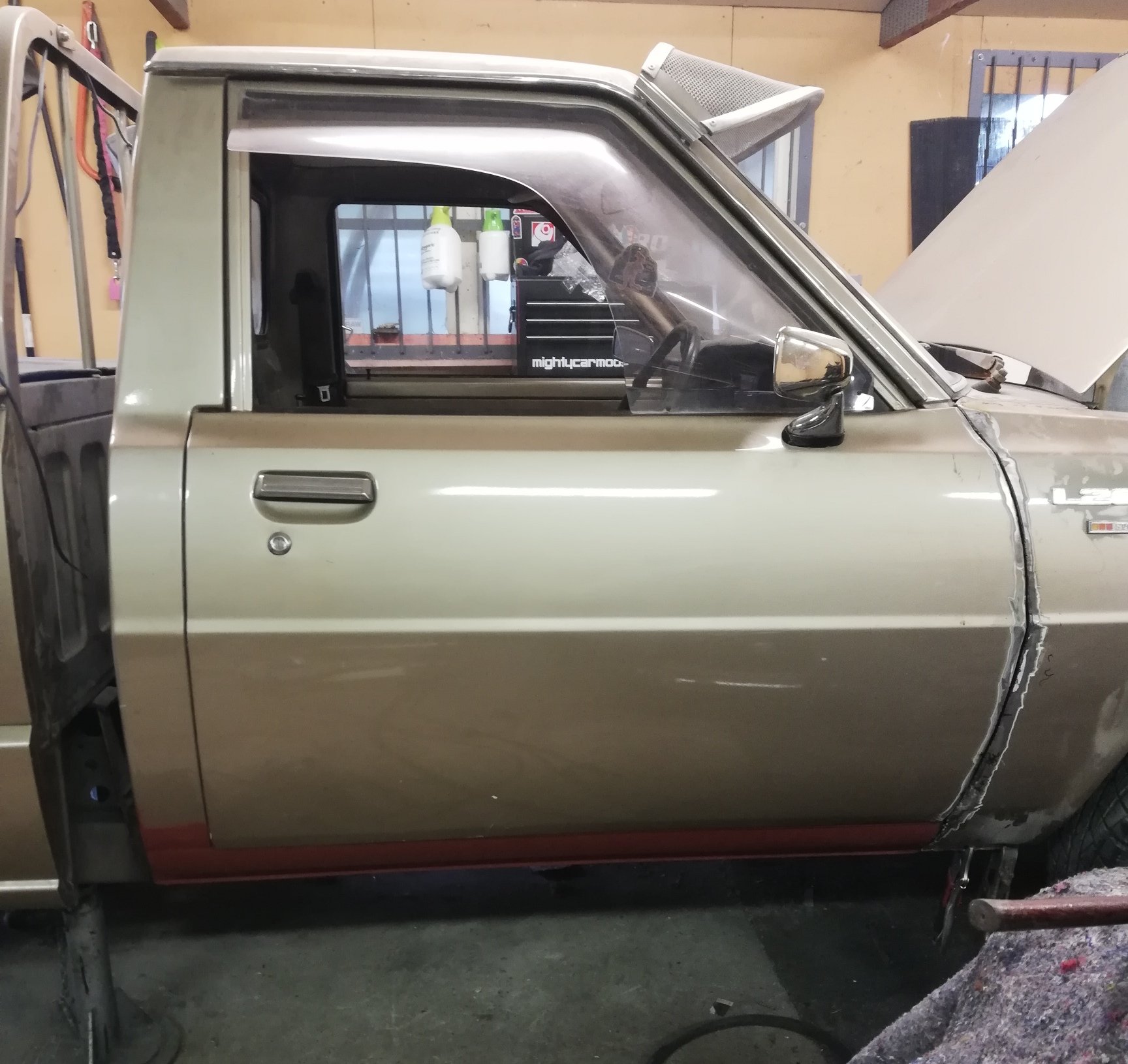
Door fits Opens without hitting anything Closes without hitting anything Is parallel with B pillar Is parallel with sill opening Sits flush everywhere All it took was totally reshaping the guard. Some spots were way out. The rear mounts had been welded on crooked. Added about 5mm in some places and skimmed a mm off in others Need to add a little at the A pillar, and probably add a little to the A pillar bottom edge itself. That lower bend/angle was different on the B pillar,door,and guard. At least it closes now FFS
5 points
-
It's woffed and regod, beats most cars on here5 points
-
OK, i tried to replace as many pictures as i could, sorry about them being mostly massive though. Wow that's an old photo. It made a friend half it's size.
5 points
-
5 points
-
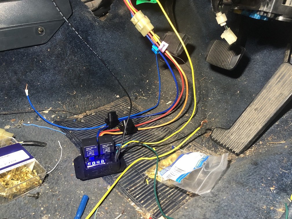
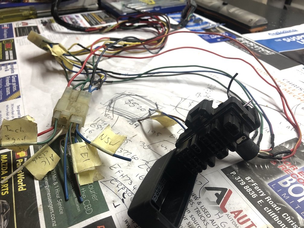
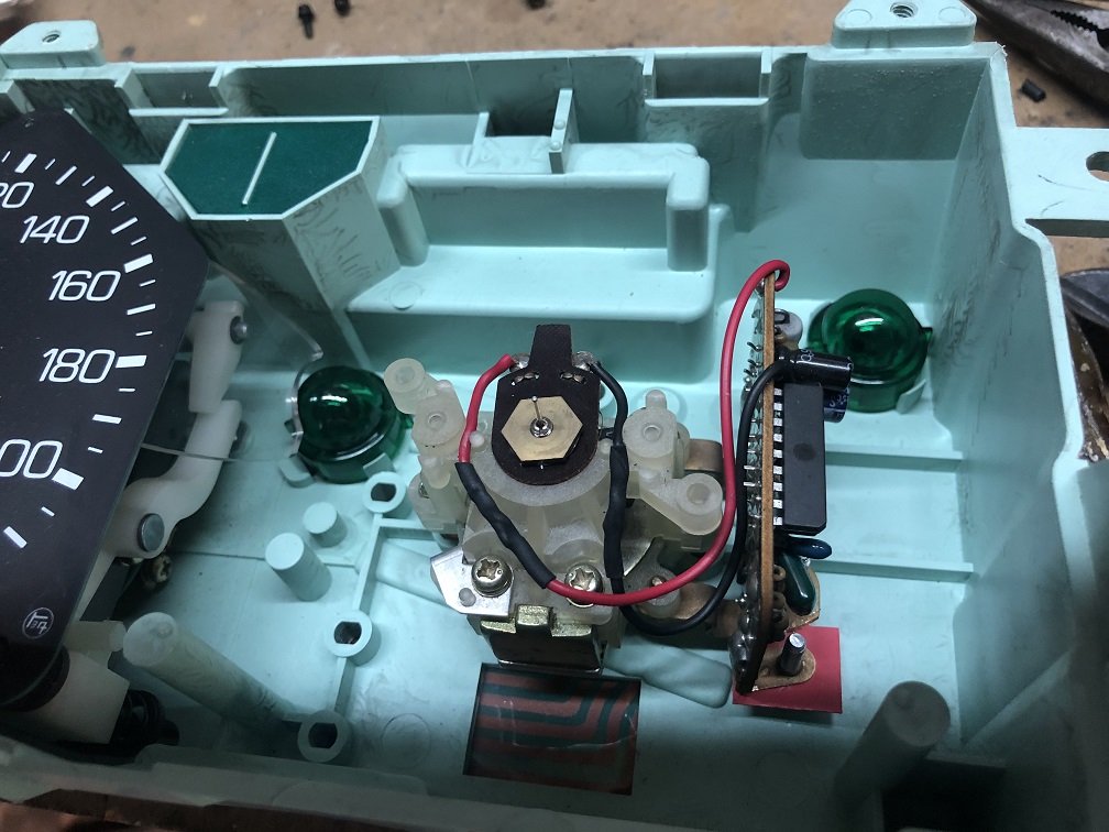
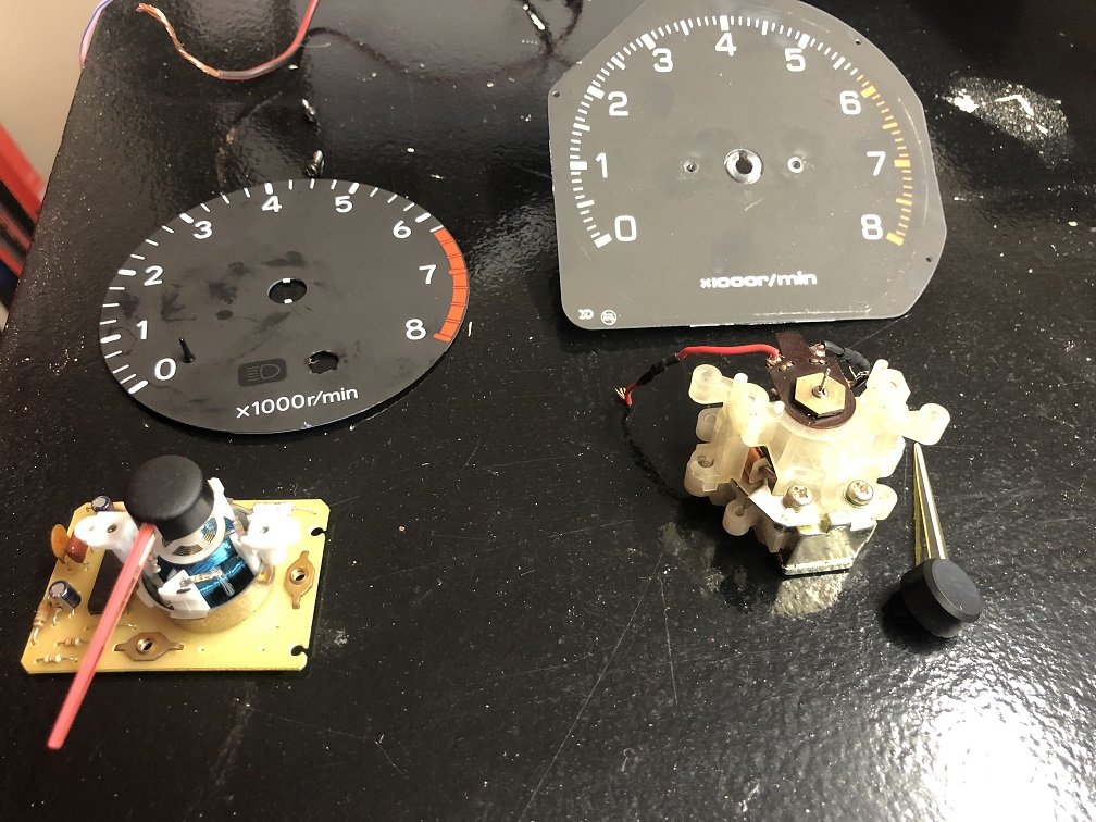
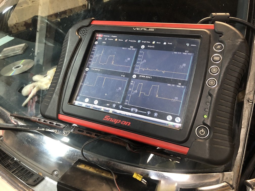
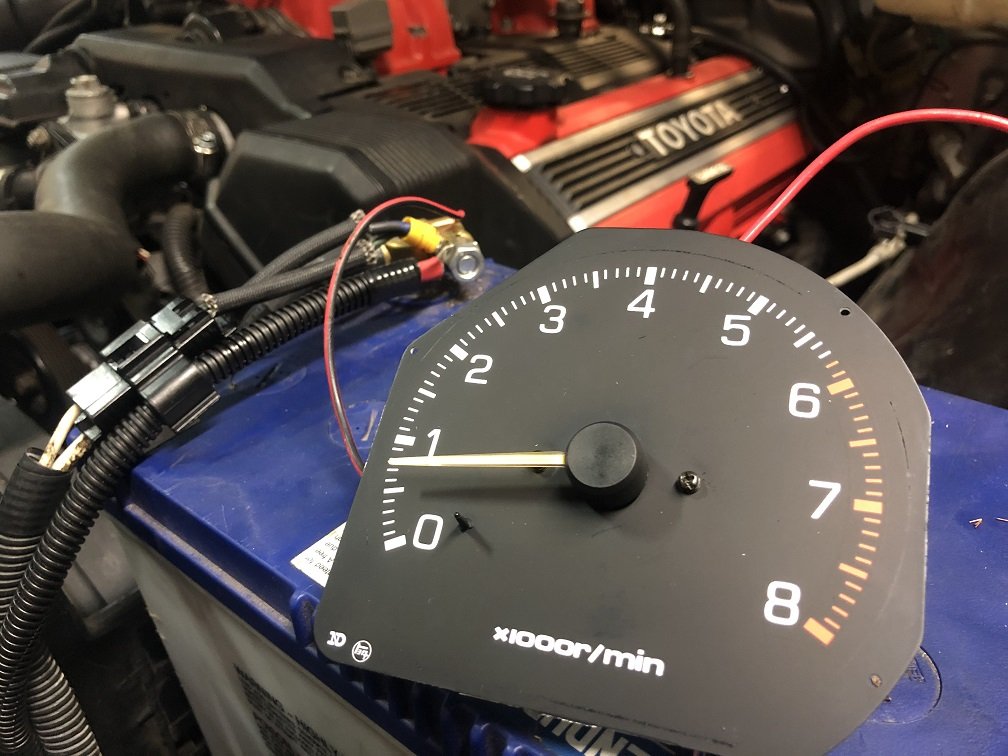
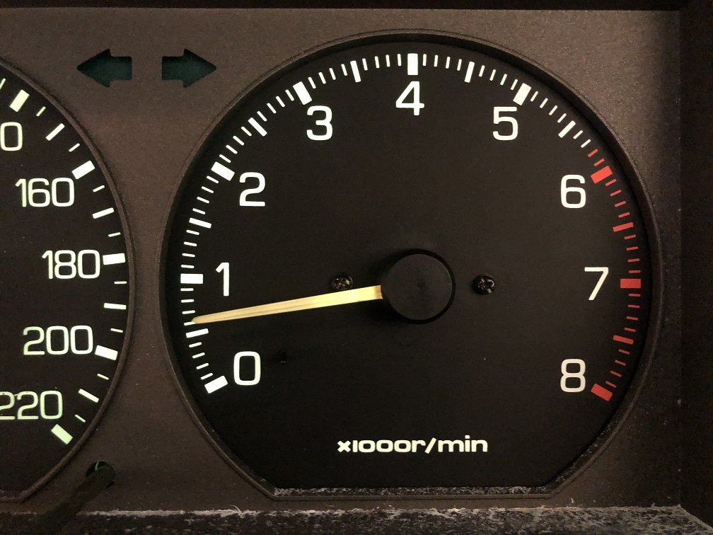
Next up is the fan controller. I got a 2 speed controller from Davies Craig, if the temp doesn't drop enough after 10 seconds of the first fan it kicks in the second fan. Also has an A/C trigger for when I get to that. I've seen a few of these mounted under bonnet but it isn't advertised as water resistant so I wired it up under the dash. That way I can have radiator temp while driving if needed. Once I mocked up length it's all been tucked under the guard with the rest of the loom. The early 1uz doesn't have a Te2 pin on the under bonnet diagnostic connector to trigger live data output, but it does have one on the ECU. I've gone and wired in a standard Toyota connector under the dash with Te2 for live data with the hope of getting a Toyobd1 Bluetooth dongle at some stage. They are hand made by a cool Canadian bloke so take some time to become available. Next up is Tach. Keen to keep the stock look inside so I swapped in the guts of a RX60 4cyl Cressida tach hoping that would give me an accurate reading. It did for about 5 minutes but then died. Swapping in the original 6cyl tach did the same thing. Maybe they didn't like the trigger signal from the ignition module? The newer style of tach from a 90's Corolla has the same bolt spacing for the card. I just needed to drill out the needle 0.5mm and fit a needle stop, the newer style has no internal limit to rotation other than the clock spring. Beautiful. I quite like the font on these older dashes the more I look at them. Next up is sorting the check engine light and possibly stealing a speed signal off the rear of the cluster for the ECU to avoid a pesky fault code.
5 points
-
Ok so it was the swing arm that was bent. Got a second hand one and banged it in for a test fit, sat perfect! Stripped off all the old paint and surface rust then brushed on some rust converter to kill all the rust in the corners. Here is as it sits now. Next is stripping again back to bare metal and hit it with the etch prime then in the 2k black. Easy.
4 points
-
Re water pump, I glue the gasket to the pump with a very light smear if rtv, then fit it and pull the bolts up tight from there. Give the o ring and where it sits a good dose of rubber grease and put it together.4 points
-
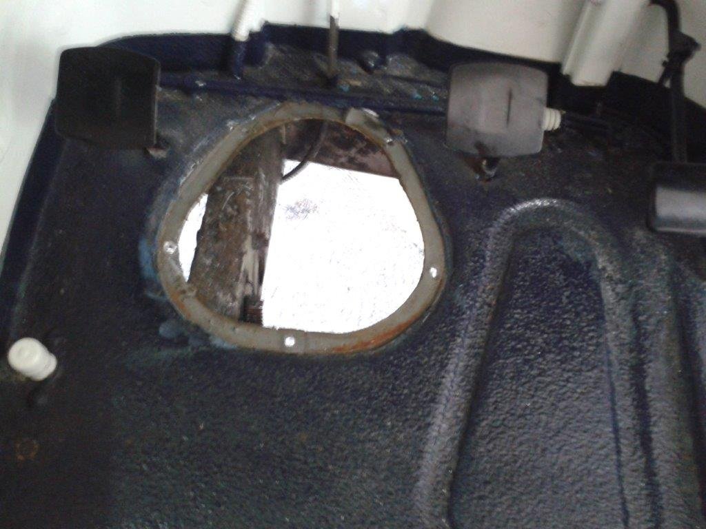
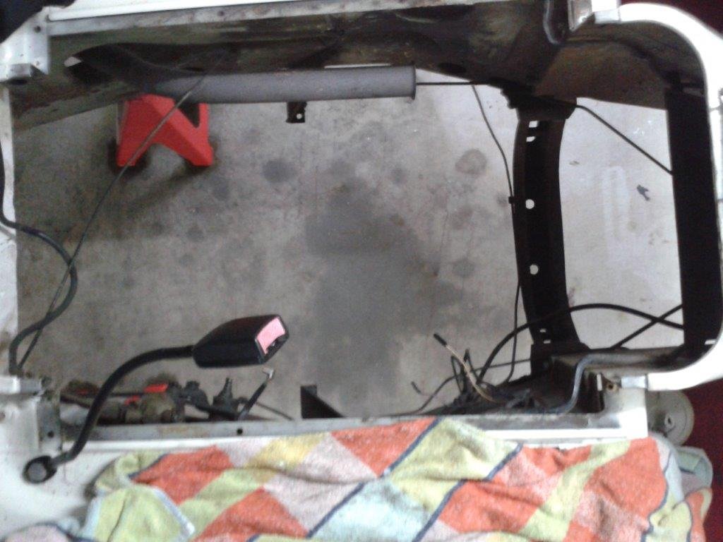
With the steering column out I quickly pulled the side cover off the steering box and a nice mixture of brown sludge, water and a little bit of oil came out. Nice ! No wonder the steering was almost seized. I'll strip the box at some stage to see if it can be saved as I'm planning to keep all of the original mechanicals intact in case someone ever wants to put it back to original. So with the column and steering box out of the way I was able to cut all of the riv nuts holding the outer edge of the hacked cover plate. I then carefully lifted the cover plate a little bit at a time whilst cutting through the Rhino line with a Stanley knife until I had gone all the way around. The final result doesn't look too bad.
4 points
-
Umm... People say strange things? https://youtu.be/VXRBjEnpMwY https://youtu.be/-MEn4SMv-4s4 points
-
Filled about 50 holes in the engine and removed all the brackets I no longer need. Laser cutting a sheet of all the filler pieces made it way quicker and easier! Where the chassis rail kicks up at the firewall is a known place where cracks can form. There was already one about 8mm long on the passengers side. Made some gussets and welded them in. Found some previous repairs around the rear hatch on the body. I think they just ground out the rust spots here and then bogged it up. Cut out and welded new steel in there. Another one here, this time just a piece of steel brazed over the top of the rust holes. Fixed! As well as a few more bits around the seal. Picked up a pair off TA22 Celica fender mirrors from YAJ, that you can kinda see. I think they look good, but hard to tell when half the cars missing. Bought a Estima F series diff. Stripped in right down, cut off all the brackets and then noticed one of the housing tubes was very bent! One end was out by at least 10mm. Had a go at straightening it, wrapped some chain around the tube and some big u-channel, and then used a bottle jack and heat to push it out. Came out pretty good, close enough to then shorten it. Drew up a jig that held it all square and inline. Shortened it by 105mm a side, so it's the same dimensions drum to drum as the factory diff. Bought some MRP adjustable 4-link arms off @Cdarust Got a Altezza Torsen LSD head to swap in. Made some upper and lower brackets for the diff. Borrowed @oftensideways rotisserie. Going to raise the rear 4-link body mounts up. About 50mm higher for the lower mount, which should make the lower arm level and somewhere between 50-100mm higher on the top arm. The angles are currently far too much and I've gone this far so may as well, will be good to get rid of the lower body mounts as they're the lowest part of the car. It shouldn't effect the rear seat too much either.4 points
-
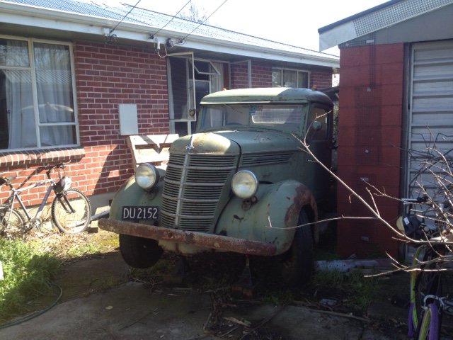
The old pics in your build thread don’t work. Can you put up a pic of the whole car so we know what all the people are talking about in your hidden camera vids?3 points
-
If you have new seals, put them in. Put rubber grease on the inner lip.2 points
-
My first thought was to try to uncover the heads of the bolts with a die grinder. Instant fail. Gotta tell you that Rhino liner is pretty tough stuff. Sticks like the proverbial. Looked underneath and discovered that the bolts fix into riv nuts, so thought okay if I can cut the riv nuts off with an angle grinder I should be able t punch whats left of the bolts out from below. Only problem is that the steering box is in the way so you can only get to one of the riv nuts. At this point I was getting pretty desperate and figured the easiest way forward would be to hack the cover plate to get the steering column and box out and then take to the riv nuts once the box was out of the way. With the steering and gear shift columns in place surrounded by the floor mounted clutch and brake pedals there isn't much space so I carefully drilled a whole lot of little pilot holes around the edge of the cover plate then followed up with a larger drill bit to overlap the holes. With the holes drilled all the way around and a straight line cut across with my tin snips it was easy enough to pull the remains of the cover plate out. Not one of my proudest moments, but needs must and I reminded myself that I'll need to fabricate a modified cover plate anyway as the HiAce steering and gearshift columns are much further apart than the Thames ones. The remains of the cover plate captured for posterity.
2 points
-
Thats a cool shot on the beach there Rusti. pretty amazed that you would put the wrong hood on your 2022 dodgy wofed electric car tho WHO WOULD DRIVE THAT2 points
-
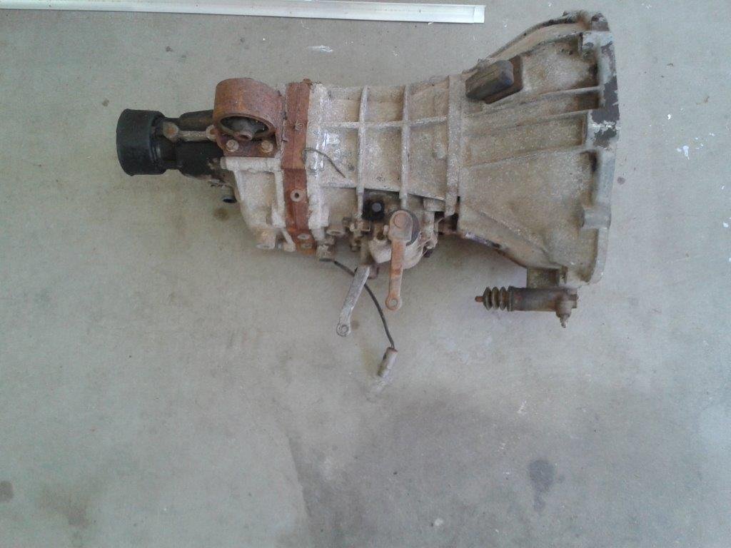
After morning smoko I thought I would crack into the next step of the "proof of concept" so I headed into the back garden to retrieve my mock-up 4Y motor out of the back of my second Toyota donor van. Loaded the motor onto my trusty wheel barrow and moved it under the back carport so that it is out of the weather. Grabbed the loose Toyota gearbox at the same time. First order of business was to take some measurements to see if the mighty 4Y will fit in the puny Thames engine box. Results of prelim measurements are as follows: Mighty 4Y - 510 mm wide at widest point. 670mm long from back of block to front of viscous fan. Thames - 505 mm wide at widest point. 654 mm long from back of block to front of fixed fan blades. So from the look of the width I should just be able to squeeze in the 4Y. From a length perspective I suspect that I may need to ditch the viscous fan on the 4Y if I'm going to retain the original Thames radiator. Nothing that an electric fan can't fix if this comes to pass. I still need to take some comparison measurements of the two gearboxes but I'll do that tomorrow.
2 points
-
2 points
-
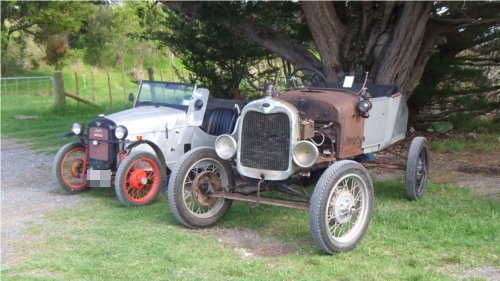
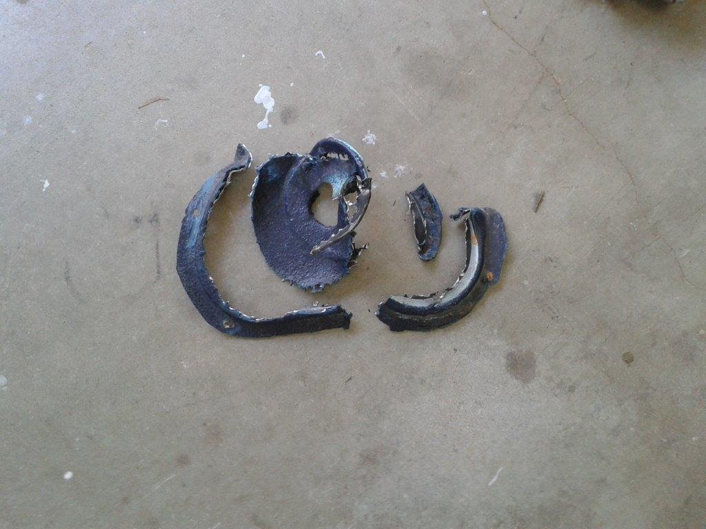
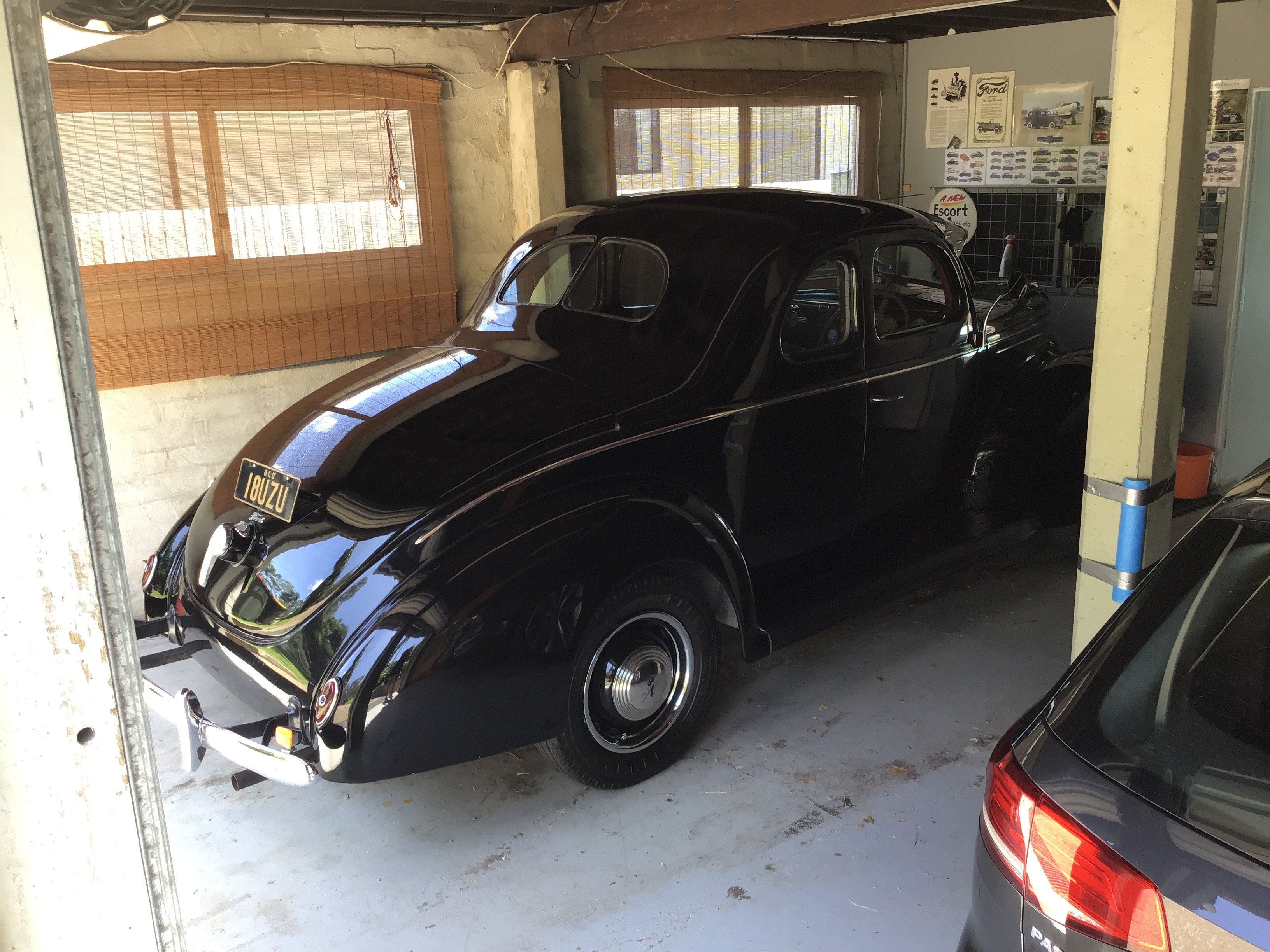
It’s been over a year since I’ve posted about the ford. I Have only just gotten it to the stage where she can be driven. The brakes took me so long to do.And all I did was replace the master, wheel cylinders and brake lines. Gave it a good clean and enjoying it before something else brakes on it.
2 points
-
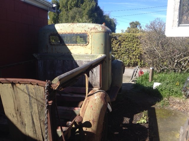
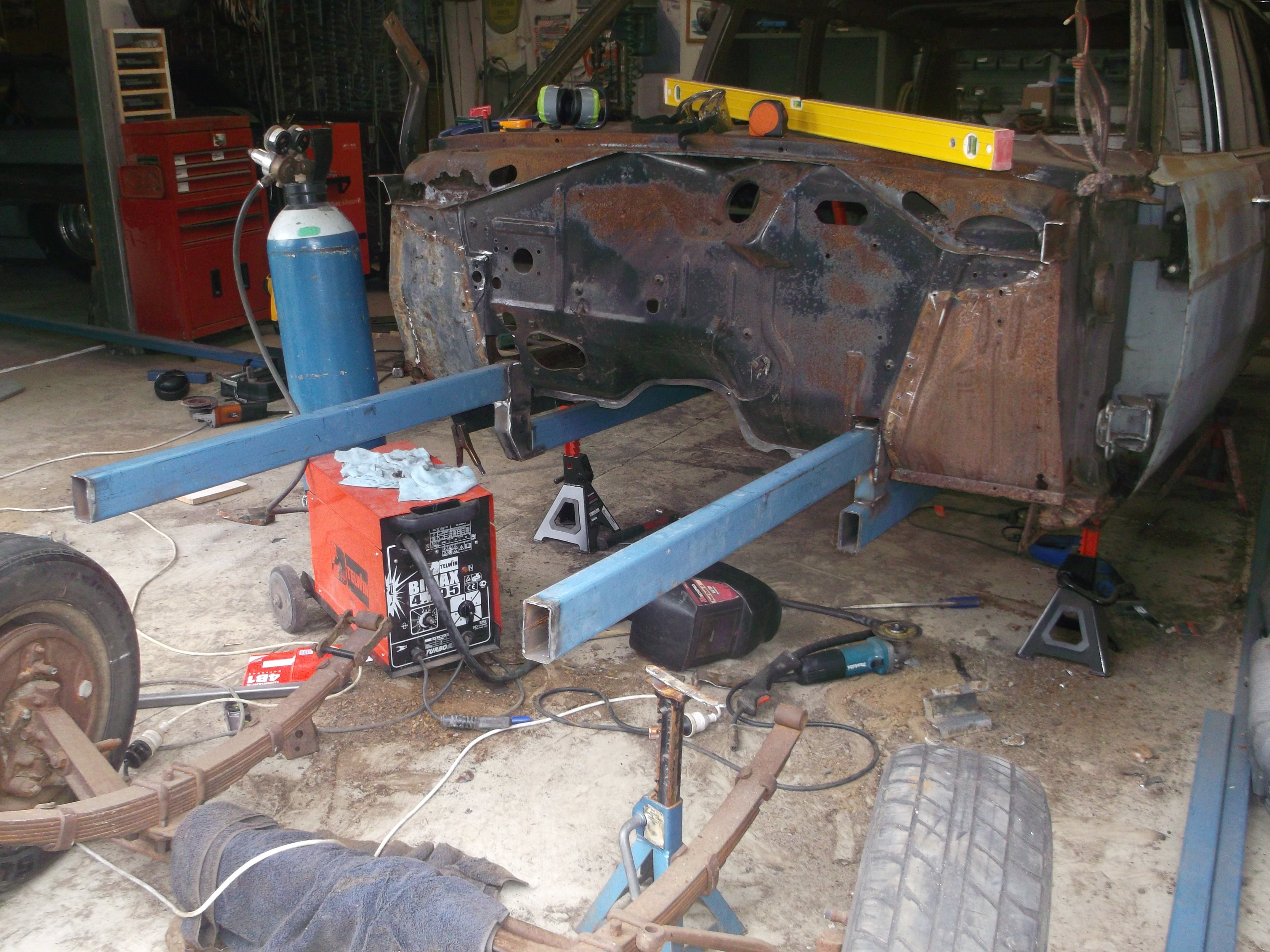
Cab off and away last night for wood rot repair. We are thinking of not painting the cab until after it's re-registered so the chassis tag & WOF sticker etc are undisturbed to make the process as smooth as possible. Now that it's short enough it can fit in the garage and we can hoist the engine out & get the chassis cleaned up. Keen to do some laps in its current state!
2 points
-
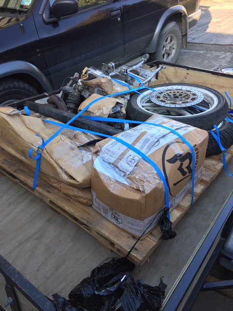
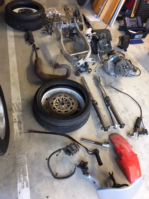
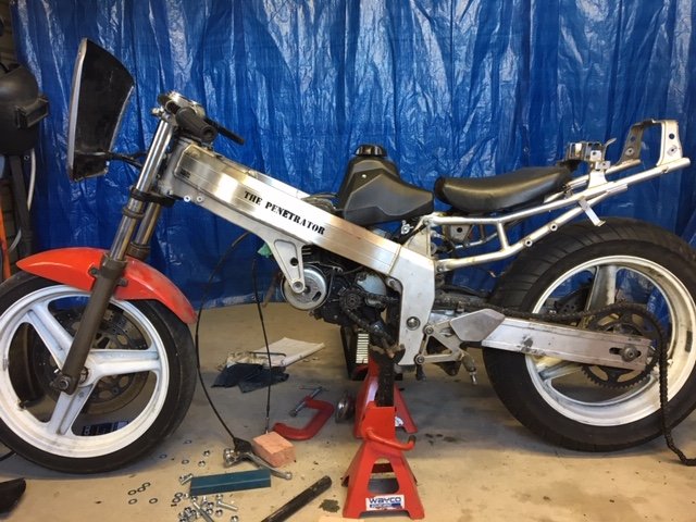
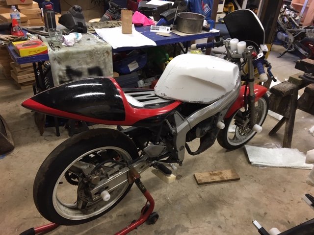
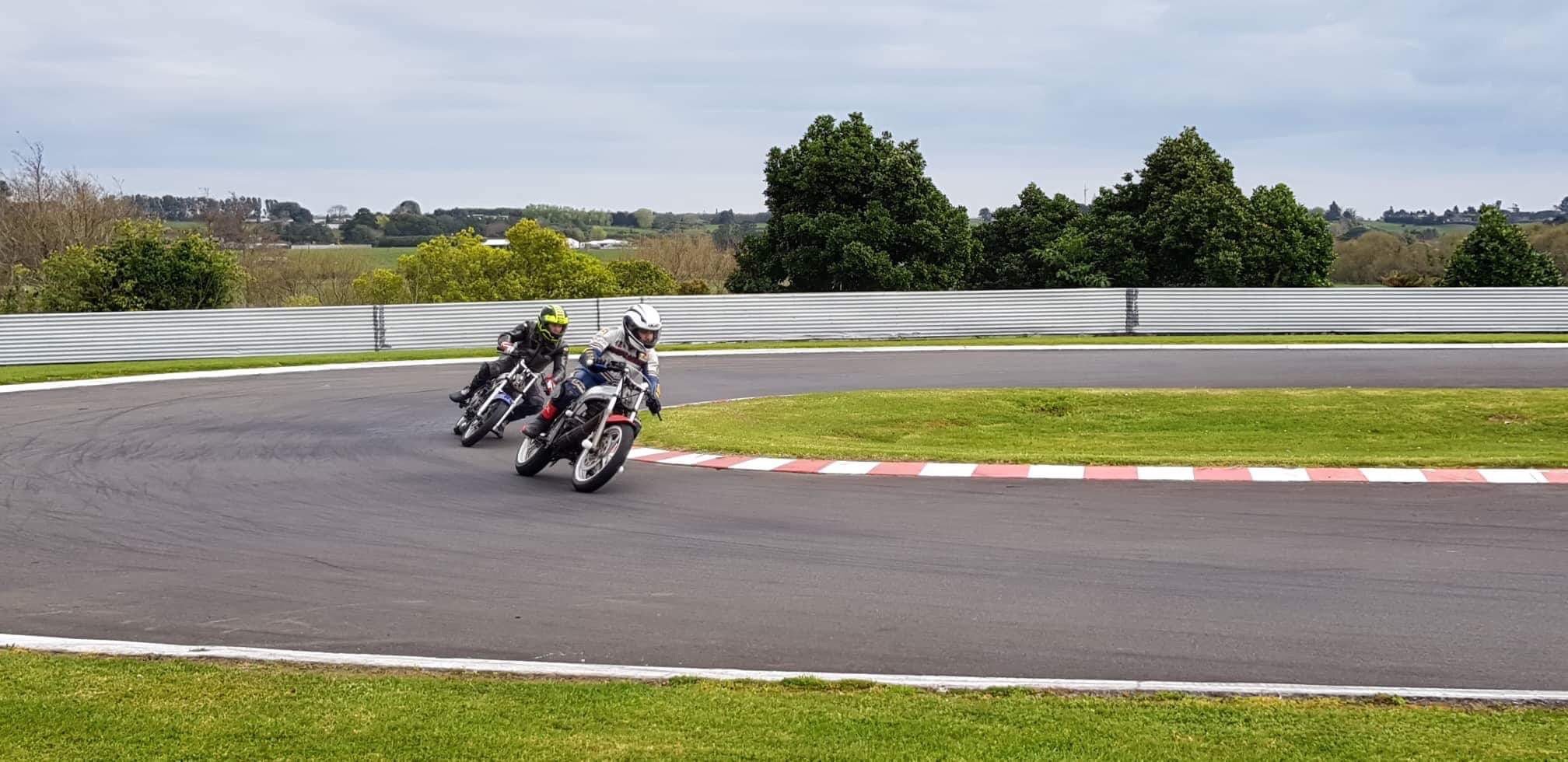
I've been meaning to start a build thread for this for ages. When we were living in Nelson I decided to get into Bucket Bike Racing. @Duke Blackwood was parting out a CBR250RR, and @Bellicose (I think) was selling a TF125, which seemed like it might be a good combination. So some deals were struck, Blackwood picked up the TF and stripped it down and put the lot on a pallet destined for Nelson. According to the timestamp on my photos it arrived on the 14th of September 2017. It didn't take me long to start mocking things up and get the motor mounted, it was a very easy fit in place of the 4 cylinder donk!
1 point
-
Today's task was to remove the old steering column, steering box and column gear shift as it's a single unit. So I lifted the floor mat in the drivers footwell as the first thing that needs to come out is the steering column surround plate that is bolted down to the floor. Now it's at this point that things start to get interesting. Firstly a little bit of background information. The previous owner bought the van to use as a delivery van for a flower shop that his wife was starting. They thought that a quirky delivery van would make a good marketing tool for the shop. Since there were going to be water filled buckets of flowers slopping around in the back they wisely decided to get the entire rear floor Rhino lined. At the same time the Rhino team lined the two front footwells. What would have been nice is if the boys at Rhino had pulled out the fixing bolts and lifted the inspection plates before sealing the floor, but that would have been to much work I'm guessing and why would you give a toss about the poor bastard that has to maintain the vehicle into the future. So the result is that the four little star headed bolts had been neatly covered with a 3mm thick coating of Rhino line and you couldn't even pick up where the lip of the panel is. FFS !
1 point
-
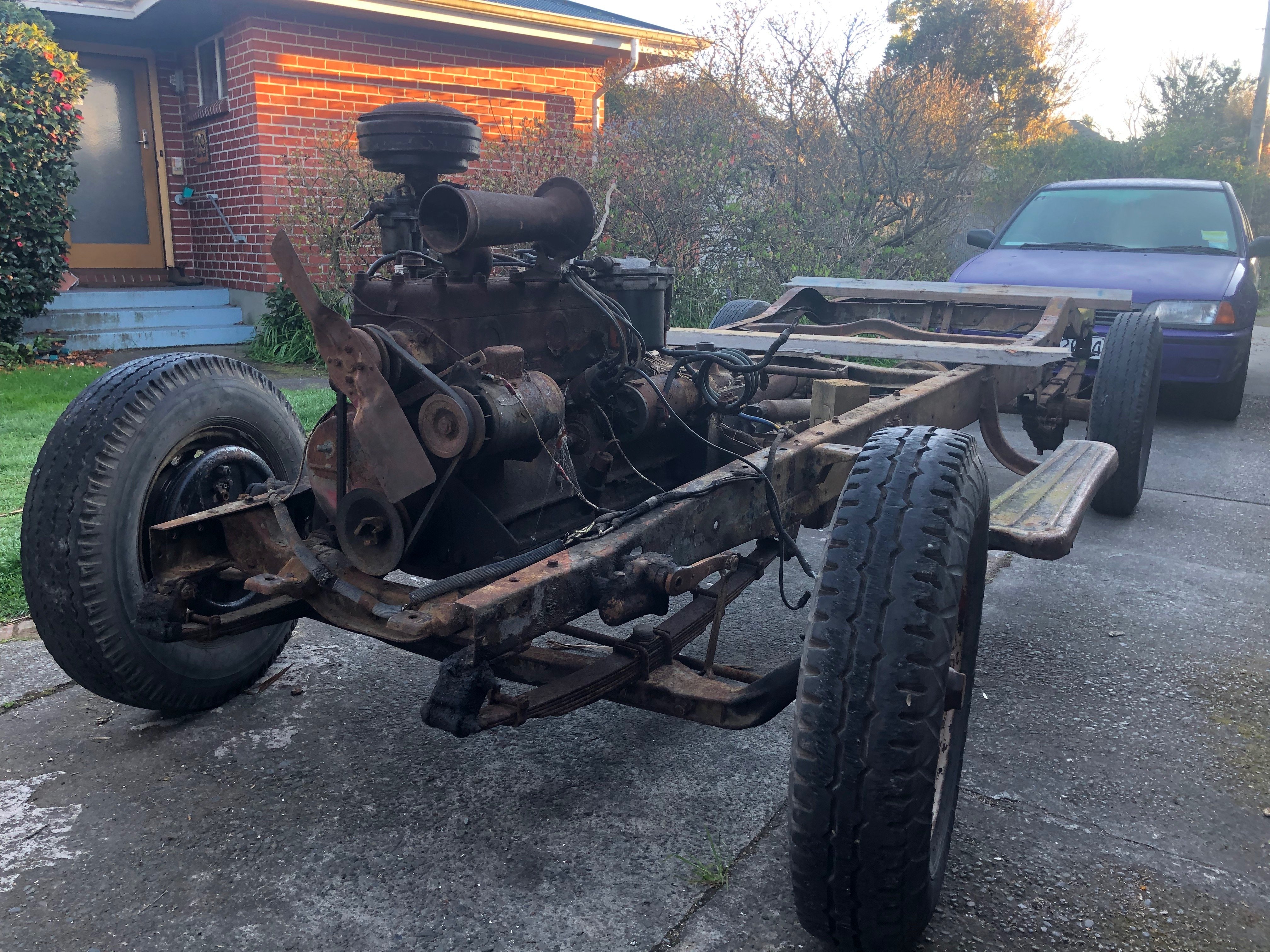
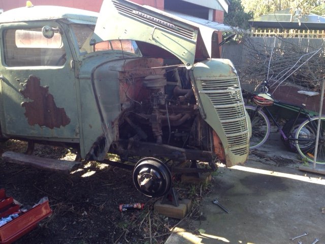
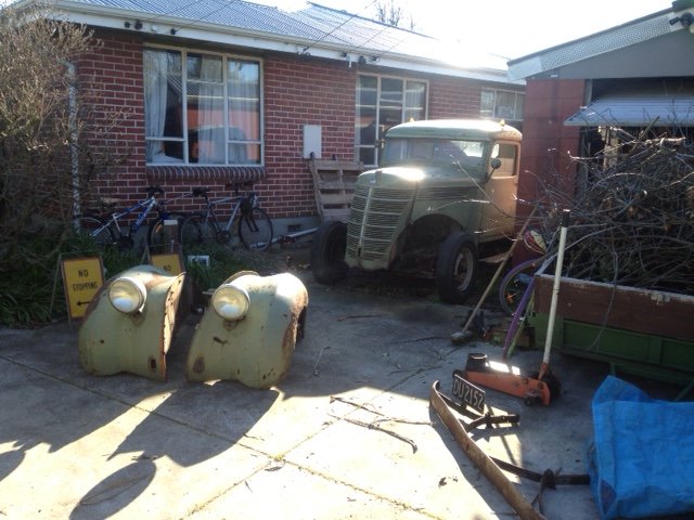
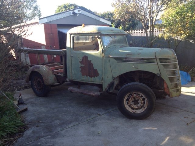
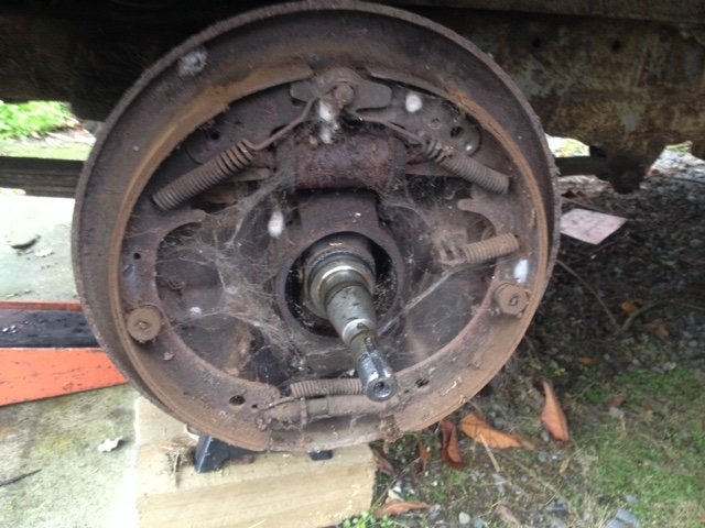
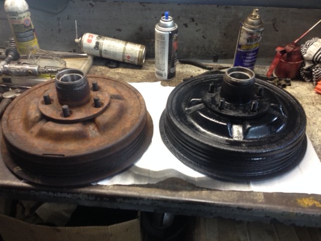
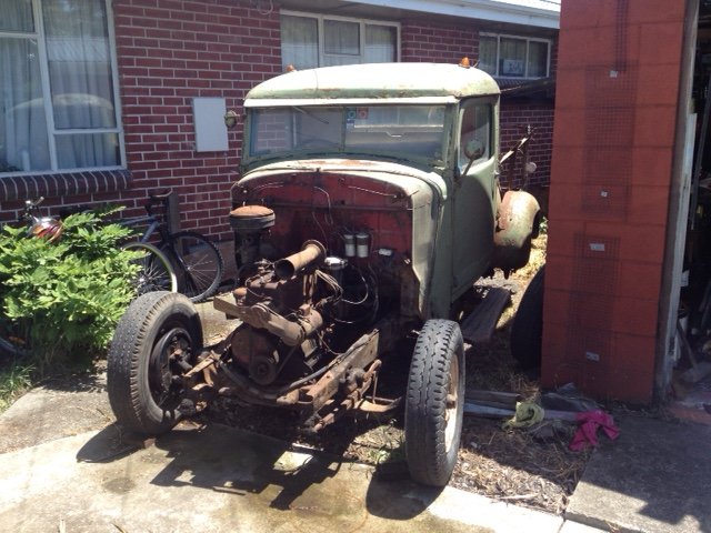
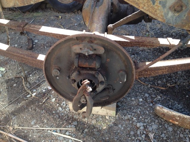
This old girl is an ex-military truck that has been in the family of a good friend of mine for a solid chunk of last century. It's only recently been pulled out from under the Macrocarpa it's called home for a few decades. The loose plan at this stage is to get it mechanically back to new, but keep it looking like it is now. Over the last few months I rebuilt the front brakes, replaced the wheel bearings & had the master cylinder re-sleeved. Today was a beaut day for getting more done. So many seized bolts though! Got both guards off & the steering linkages straightened/cleaned up. The front is back on the ground, next I'll tackle the rear brakes & fuel tank. It hasn't run in a bit, but does turn over by hand. I'll get the engine out for a look over after I get the body off. I do like the rat-rod look. We won't be going that way, but I can see the appeal. Anyone here play with these old things? Anything I should look out for? Cheers!
1 point
-
Wat year? Live in the now maaaan1 point
-
I run a breaker in my racecar as the battery is in the boot never had any issues with it and it will hold up to starting load (non gear reduction starter on a highly strung high comp 4 banger) . Most fuses have a trip curve of sorts to deal with peak loading vs constant overloading.1 point
-
Here's the master cylinder rebuild: I won’t go into great depth of each step, as they are quite well covered by various workshop manuals (I referred to the Haynes manual, as well as the instruction from the rebuild kit for guidance). Here is the master cylinder in place in the car, of course to do the rebuild we need to remove it. To remove it, disconnect the brake lines from the master cylinder (I used some plastic bags and tape to cover the ends of the lines), but before doing so, remove as much brake fluid as possible from the reservoir (I used a syringe). To provide better access to the line in the middle of the master cylinder, I removed the power steering reservoir (only two bolts), that made life a lot easier. Then you remove two nuts attached to the brake booster and it should come away. Don’t forget to disconnect the brake fluid senor wiring. And here is the removed master cylinder and reservoir. Also, I thought I’d put a photo up of the kit box, just in case anyone is interested, also has the supplier’s details too. To remove the reservoir from the master cylinder, the holding pin needs to be removed (referring to the photo below, it’s in the bottom of the ‘V’ of the reservoir outlets). I found this extremely stiff and took quite a bit of effort from using a hammer to knock it out, you’ll also need a dowel or screw driver etc with which to tap it through the master cylinder casing and finally remove. My advice would be is take your time. The reservoir should then pull away with a bit of effort from the rubber grommets on the inlet ports (which in turn need to come out too). The next step is to remove the two pistons within the master cylinder, these are held in place by a pin that passes through a slot on the primary piston and through to the other side of the cylinder casing. The Haynes manual notes that a magnetic should be used, but the image shown isn’t very clear/easy to understand (well to me at least). To access the free end of the pin, you need a magnet that can fit into the inlet port, I did not have such a magnet (I tried a magnetic tipped screw driver, but this wasn’t strong enough). Not really wanting to get off my arse and buy a suitable magnet, I improvised, borrowing one of the magnets on the wardrobe door lock (the type that you screw into the top of the door and other in the door frame) and ‘attaching’ one of my socket drill bits to it. This worked nicely. With the pin removed, a gentle tap of the master cylinder on some wood and the pistons came out. Here is the disassembled master cylinder (note in this photo the piston locking pin is missing). As you can see, (an assumed) 33 years have taken their toll on the inlet rubbers. Here is what you receive within the rebuild kit, I used all the new parts, apart from the piston locking pin. The original one didn’t have the chambered edges and I preferred that. I inspected the bore of the master cylinder and couldn’t see or feel (as far as much fingers could reach) anything that jumped out at me as being suspect, so proceeded with the rebuild. Here the secondary piston is being installed, after the primary one. Care should be taken when placing the pistons into the cylinder, the instructions with the kit covered this well, stating that they should be slightly rotated combined with slight up and down movements (don’t want the spring to score the bore etc). Also of course, apply clean brake fluid to the pistons prior to installing them and also note the position of the slot on the primary piston, as to ensure that it lines up with the opening for the pin. And here is the master cylinder rebuilt, just awaiting for the reservoir to be installed. I don’t have a photo of the completed one with the reservoir in place, it must have slipped my mind, as at that point I really fancied a beer!1 point
-
Original plan was to pull the steering out of the Thames today, but I woke up to a sunny day after three days of intermittent rain so figured I'd take the opportunity to remove the replacement front end from the mighty Mitsubishi Starwagon as its currently sitting out in the elements. Cranked up some Lynyrd Skynyrd at full pitch to get the blood flowing and in next to no time this happened :
1 point
-
Which left me with this vast open space .... not.
1 point
-
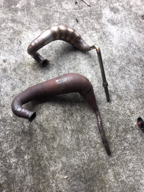
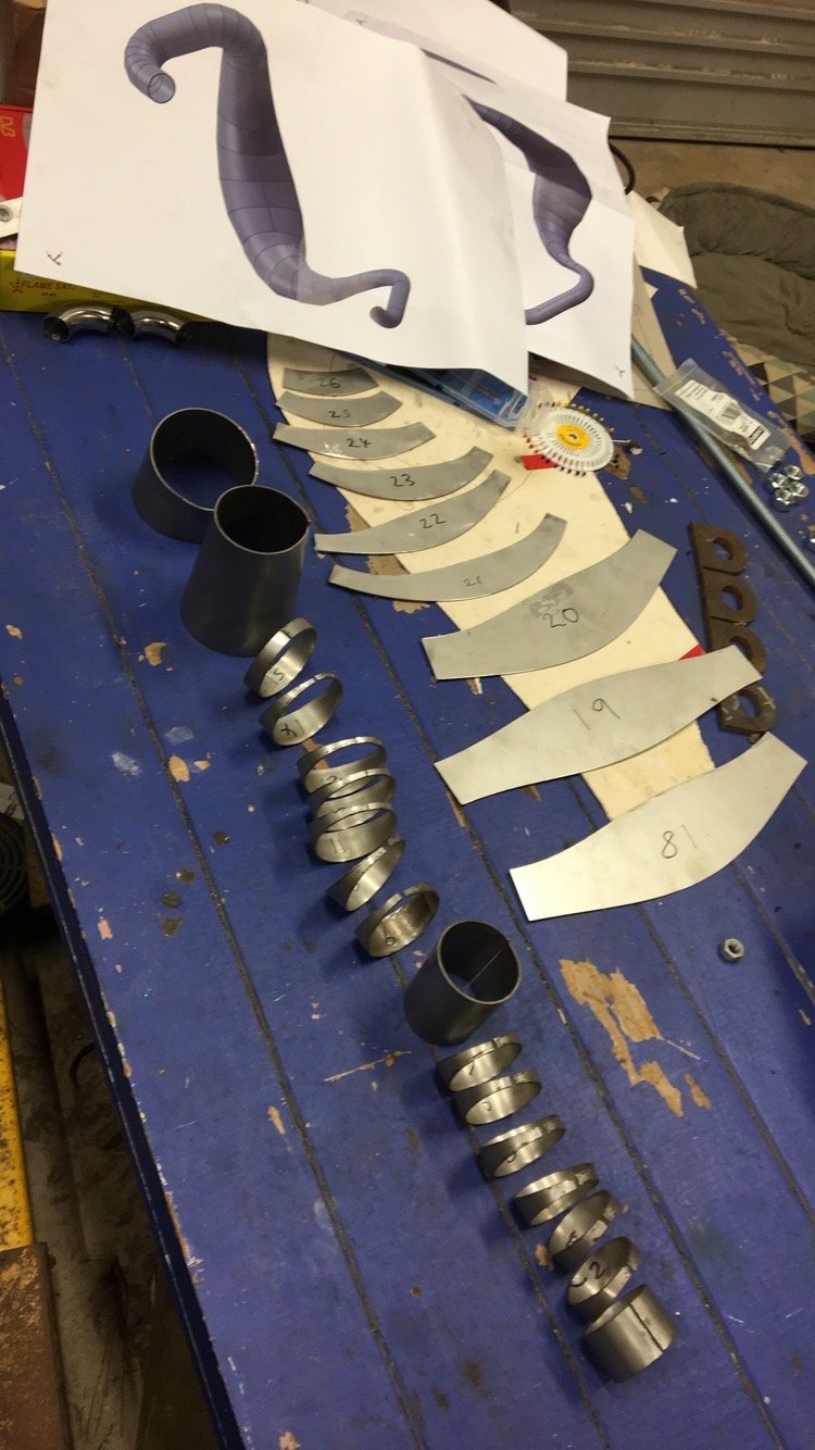
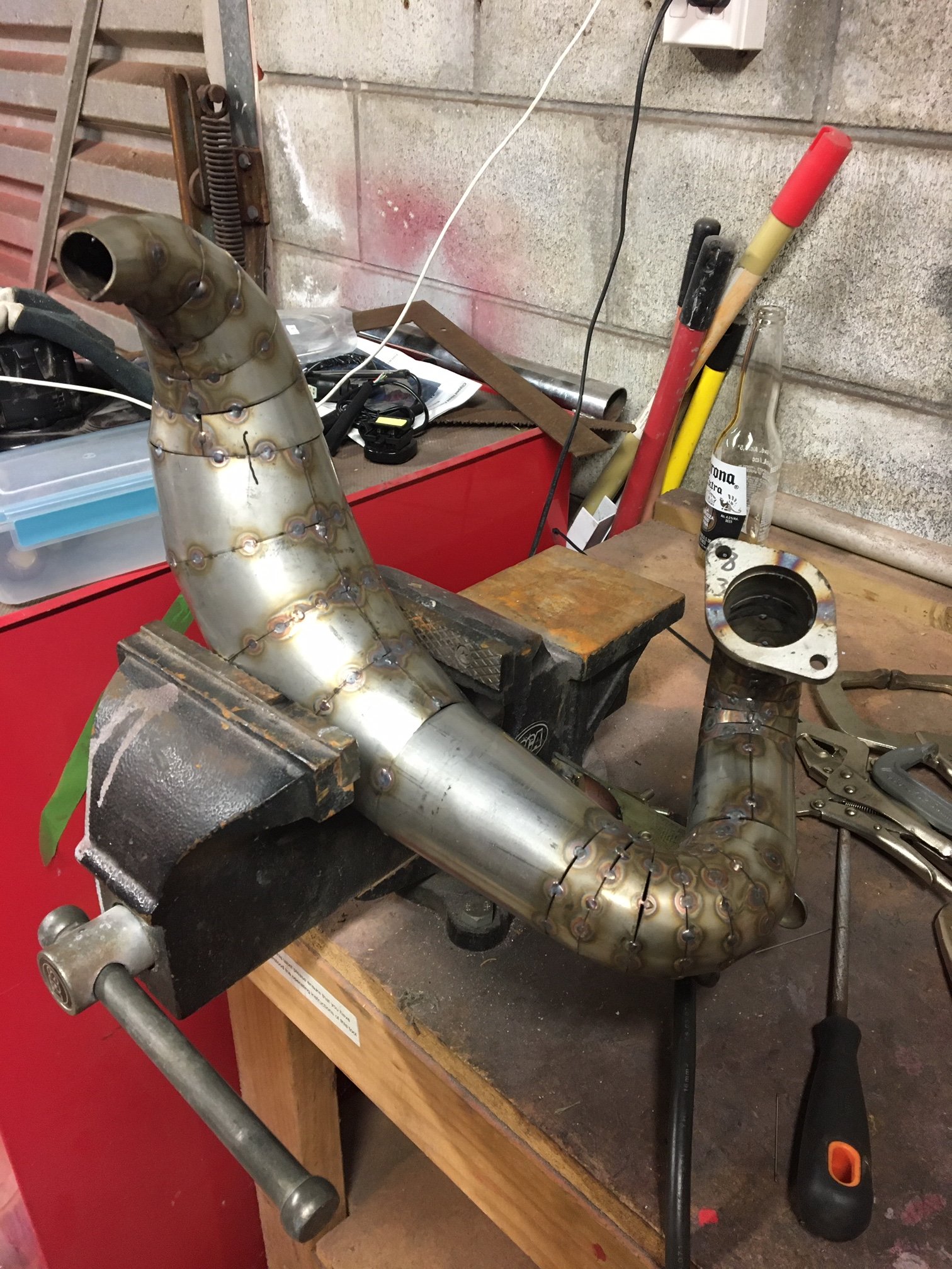
I got lucky enough to be able to spend a whole night in the shed on Friday. So I kept welding until the pipe was finished... It was a massive effort. Severely underestimated. It was race day on Sunday, so I took both pipes along to back-to-back test them. I knew vibration was still going to be a big issue so was gonna run each pipe in one session and then ride an FXR for the rest of the day. The new pipe was good, the power band is a little wider and smoother, from ~9000rpm to about 11,700rpm, and I can tell its got a wee bit more power because now I get it to top gear before the end of the straight. Unfortunately it only got about 3 laps into the test before I could hear it getting louder, and as I pulled into the pits it got VERY loud. The vibrations had made the bolts come loose in the past, so I had tie wired them (loctite and spring washers wasn't doing it). Being tie wired, rather than rattling out, they have vibrated and pulled and stripped all the threads out of the barrel Time to balance that crank! I'm happy that the pipe has made a gain though. Now I'm going to do some research about nozzles to increase the stinger size and deal with its length.
1 point
-
1 point
-
got both new rails on today , next is to build a flip front
1 point
-
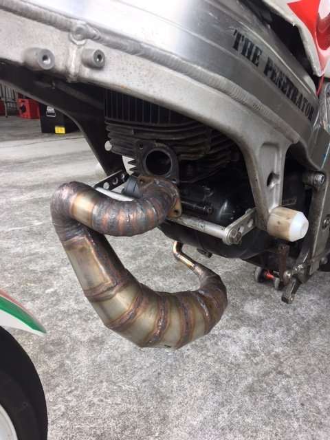
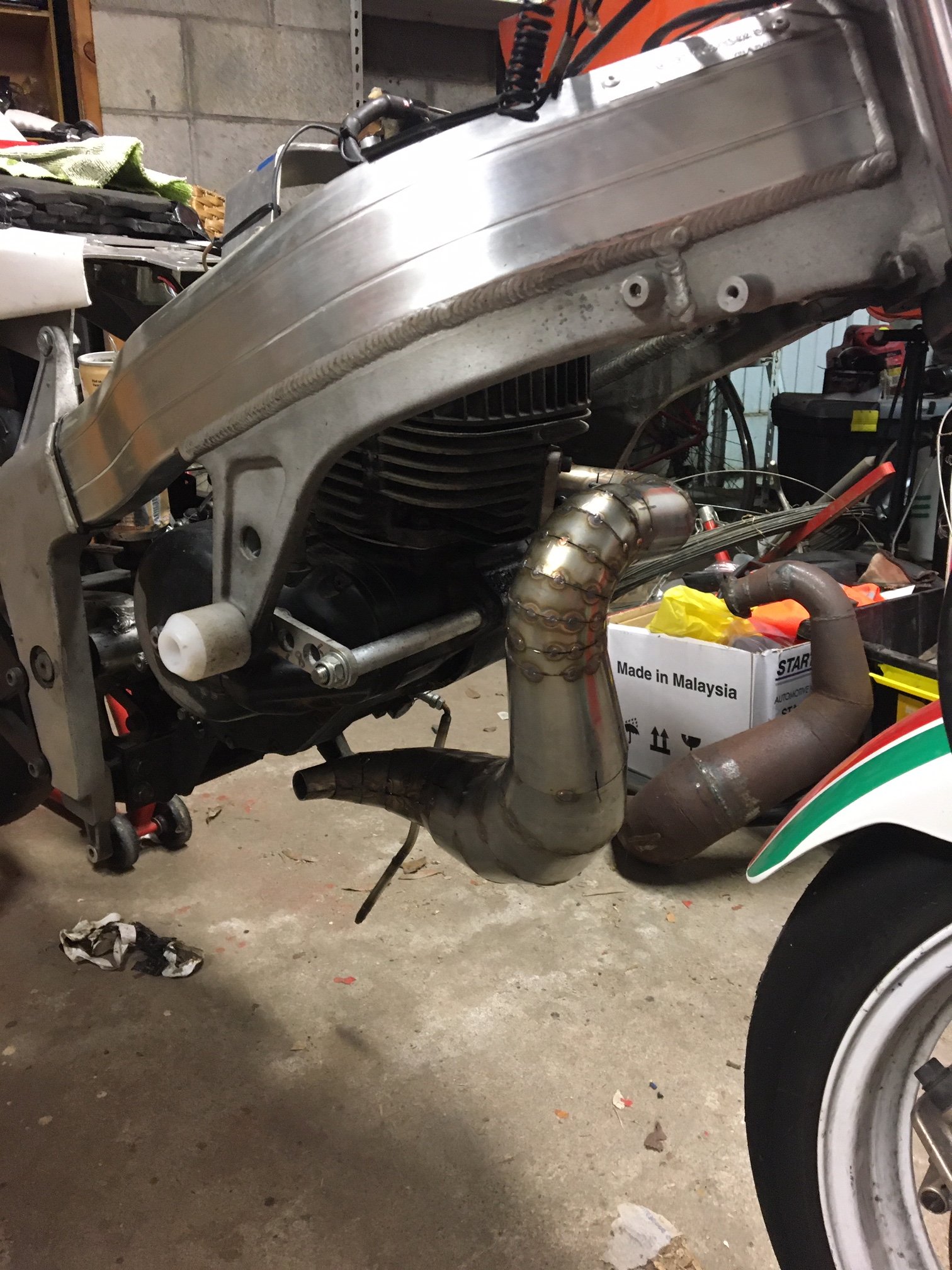
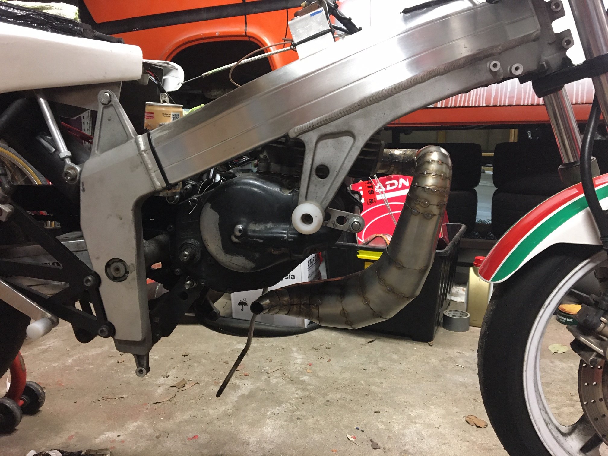
Spacer: So after all those drastic mods I was at this stage running the final version of the bastardized random unknown pipe and now on a 24mm PRC Maikuni Flat Slid Carb. After a chunk of trial and error tuning I observed a massive increase in power, and the rev limit went from topping out at 7k to zipping past 11000rpm (where I sook out and change gears). Unfortunately, these are only balanced for 6000rpm... so now your hands go numb and every bolt on the frame comes undone in seconds. Its also still painfully slow compared to the stadard FXR150's. So for now its back in the laboratory while I finish welding up the pipe and pull the crank to balance it. While I've got it apart I will take some more off the barrel to get the squish down, and if funds allow, I'll re-bore it and might look at fitting a new piston to get better ring options, RG500 thingy's look like they might be a good fit. That's the whole story up to date now. Edit: you can see in this photo how pissed the piston is sitting on the barrel. This is because of the 10mm cut from the skirt on the inlet side with my precision 5" grinder.
1 point
-
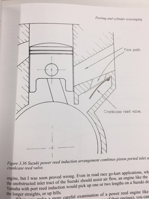
The last piece of the puzzle to date has been the engine itself. My search for that elusive horsepower led me down the rabbit hole of port timing. I raised the barrel 1.5mm Raised the exhaust port roof 6.6mm (+ the 1.5mm) Lowered the floor of the inlet port 10mm Cut the inlet side of the piston skirt 10mm This theoretically results in port timings of 195°Ex/128°Tr/185°In, however I haven't checked it with a degree wheel yet. Originals were 155.5°Ex/118°Tr (didn't bother to measure inlet because of the reeds). As well as taking the 1.5mm back from the top of the barrel, I machined the head about 1.1mm and used a thinner gasket to get from 17.5cc to 13.7cc (8:1CR to 10:1CR - Uncorrected) This gave me a squish band of about 1.8mm, which is about 0.8mm higher than I would like it to be. These engines have a bizarre piston port/reed inlet system that suzuki trialled in the 70's. Basically it just ends up being shit at both. So I've blocked up the reed port and massively adjusted the piston port to make it a piston port engine only. Comparison of before and after inlet port sizing: Have you ever seen someone precision machining their piston with an angle grinder? You have now!
1 point
-
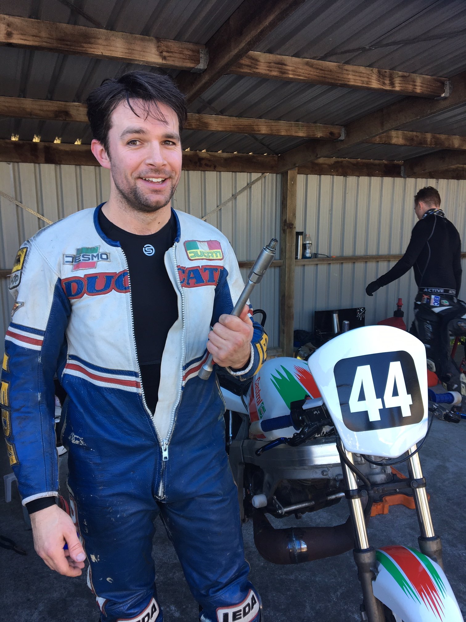
And then, this one time at band camp... I pushed it around and around and around the dummy grid wondering why it wouldn't start, only to get back to the pits after watching the race and find this sitting on my toolbox...
1 point
-
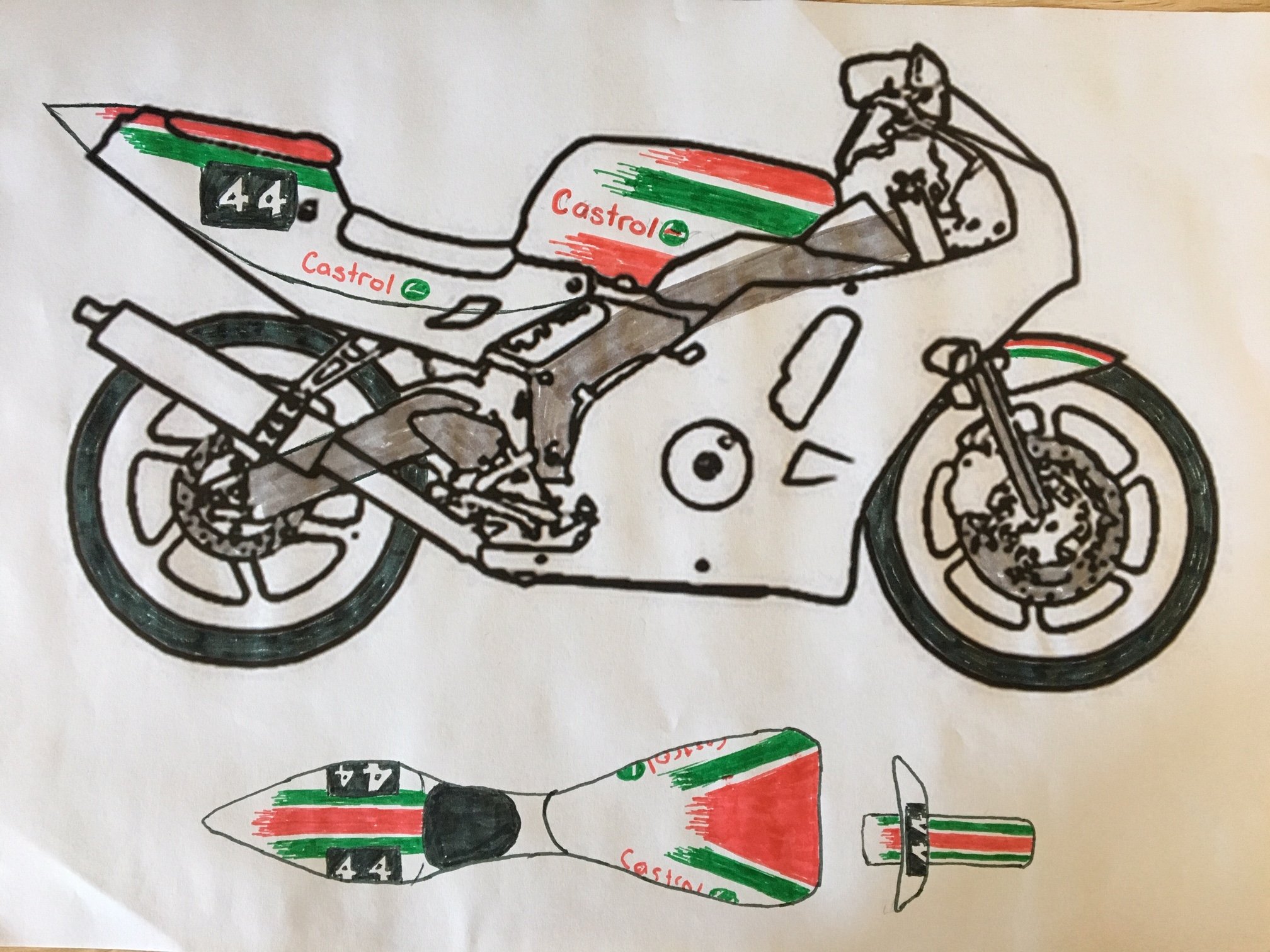
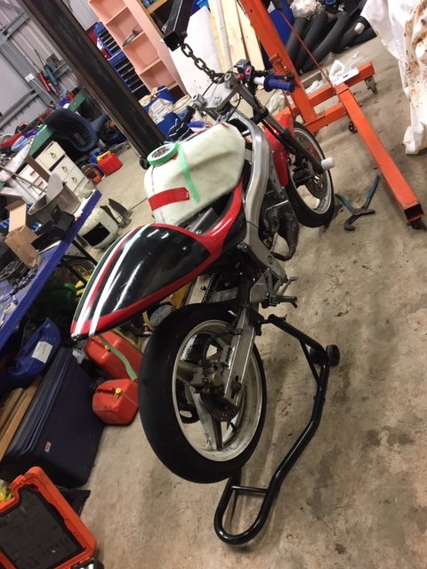
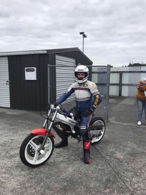
I also made it look heaps better, cos if its gonna be slow its gotta look good doing it.
1 point
-
Now I just have heaps of welding to do...
1 point
-
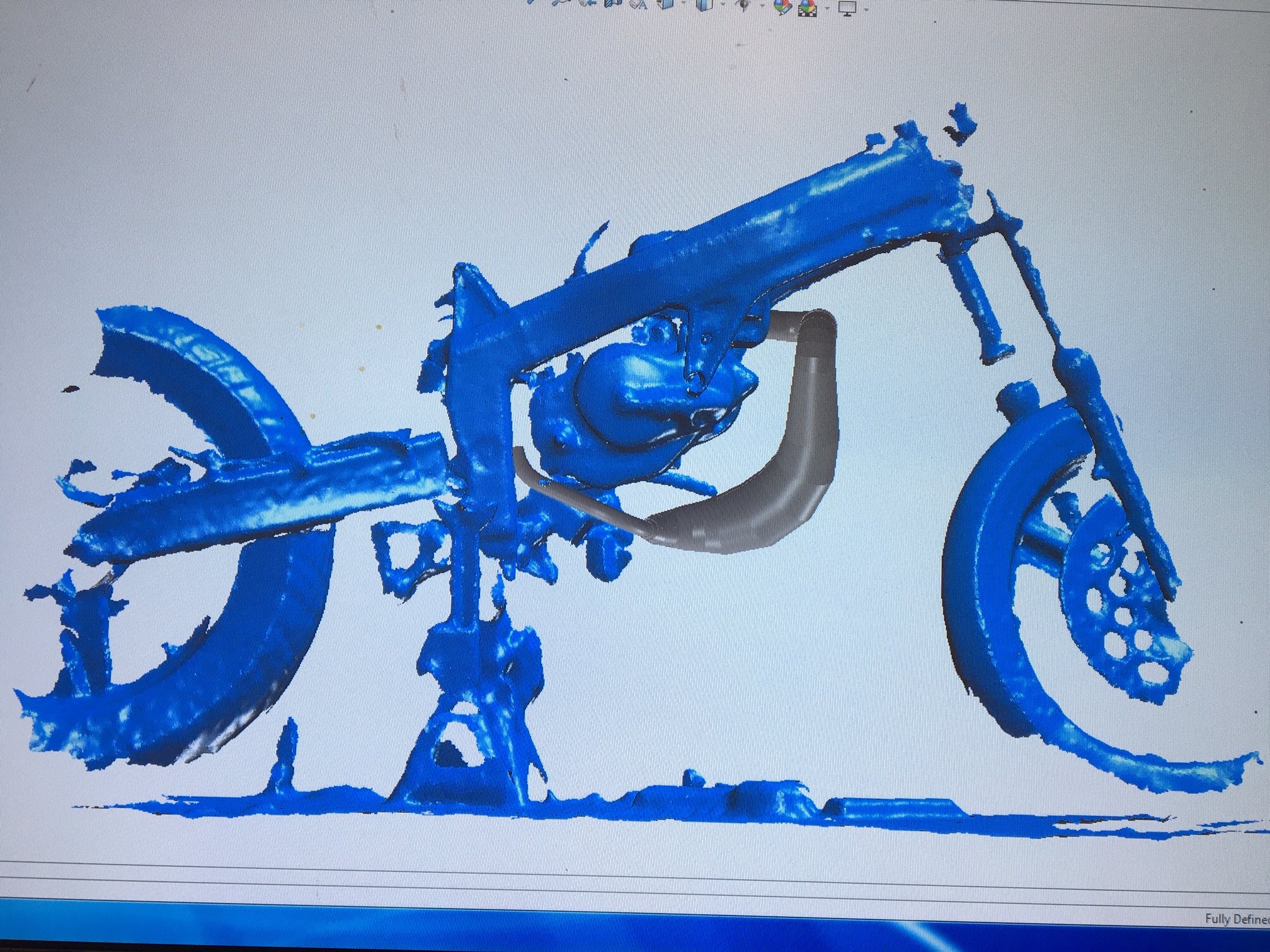
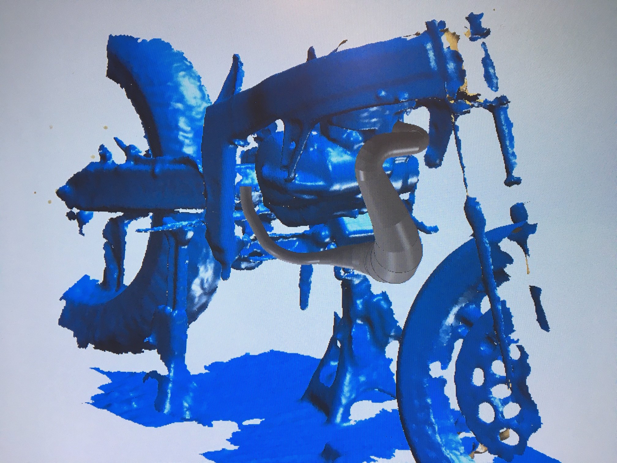
3D scanned with an xbox kinect 3D camera and then modelled using solidworks sheet-metal
1 point
-
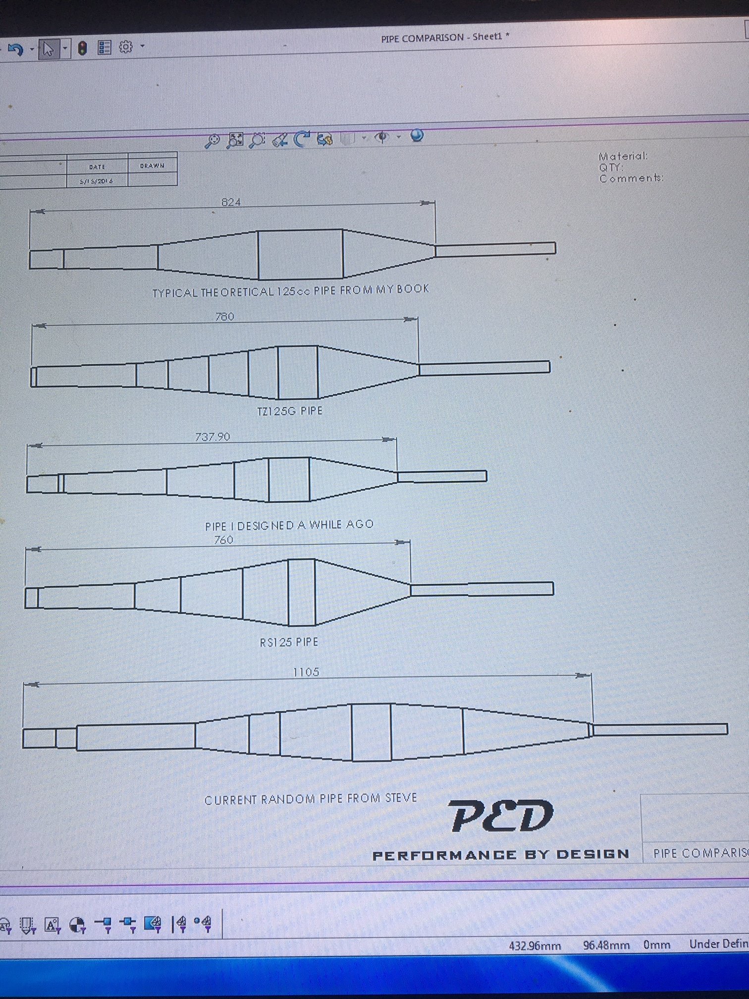
Pipe wise, initially i made the most bastardized hack and weld job of the original TF125 pipe just to get it going. I've read a bit on 2-stroke tuning in recent time and knowing what I know now, what I did to that pipe would genuinely have been quite an improvement over standard i think. Unfortunately though the bike has always been horrendously down on power compared to all the other F4 bucket bikes so I started playing. First up was a spare chamber that we had floating around in a box of parts. Completely unknown origin, looks home made. I made it fit, again using the bastardize technique. Its got a massive mid section diameter and was horrendously long with a looooong header. So it had wicked pull off the corners to about 4000rpm and then wouldn't rev past about 6000rpm... not exactly race winning stuff going on here... So I took some length out of the header and shortened it up by quite some margin. This made the bike rev to around 7000rpm, with little to no improvement otherwise, and I couldn't for the life of me get the carburetion to work. From the book I've read and some software that the internet gave me, I've applied some technology and started on building a pipe that is actually designed for this engine and application.
1 point
-
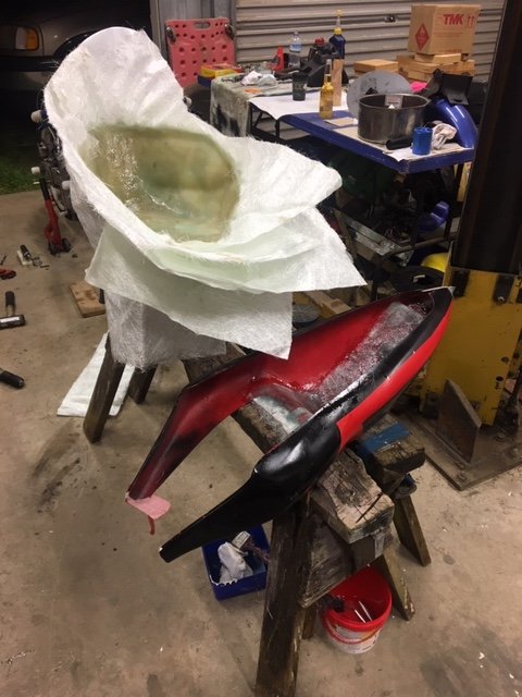
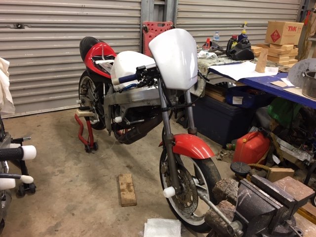
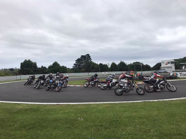
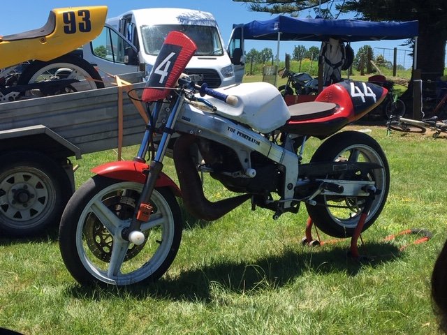
Next up was to get onto some fibreglassing. As I had moved back to New Plymouth and was much closer to Blackwood manor and hence the original MC19 tank, I stuck the glued foam abomination on the top shelf in my workshop and took a mold off the original tank. Not having done any fibreglassing before, I massively over did it, its about 10mm thick in places where the sheets folded over themselves and weighs nearly as much as a steel one I scored a TZR250 race tail section off the buy and sell but it was massively wide, so I cut about 125mm strip out of the middle and glassed it back together. This left it with a cool pointy tail thing going on. About this stage we got the racing off the ground. Our first real event we invited the bucket racing guys from wellington and had an awesome field of about 15 bikes, this was awesome as it really got some hype going for us and we built numbers very quickly. We have a solid 9 or so bikes turning up most club days now and only a year in. We had a roll of red duct tape that was nearly a perfect match for the existing red paint on the tail and front mudguard, so for most of its racing so far the bike has been liveried with tape. Great from afar but far from great.
1 point
-
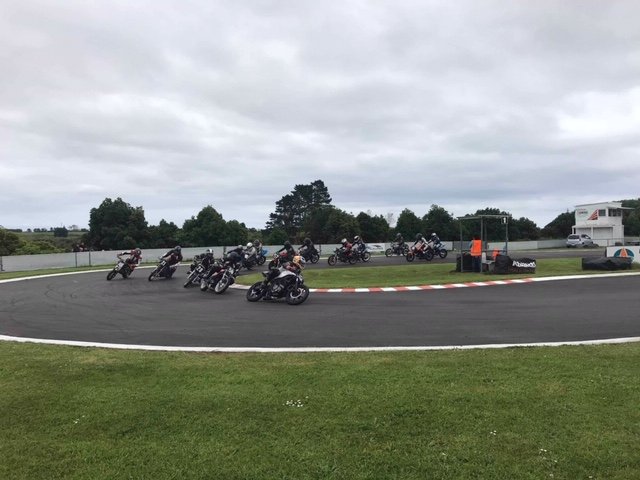
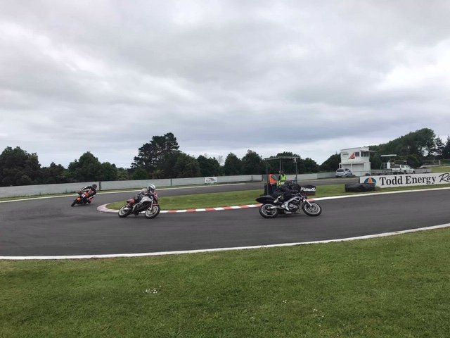
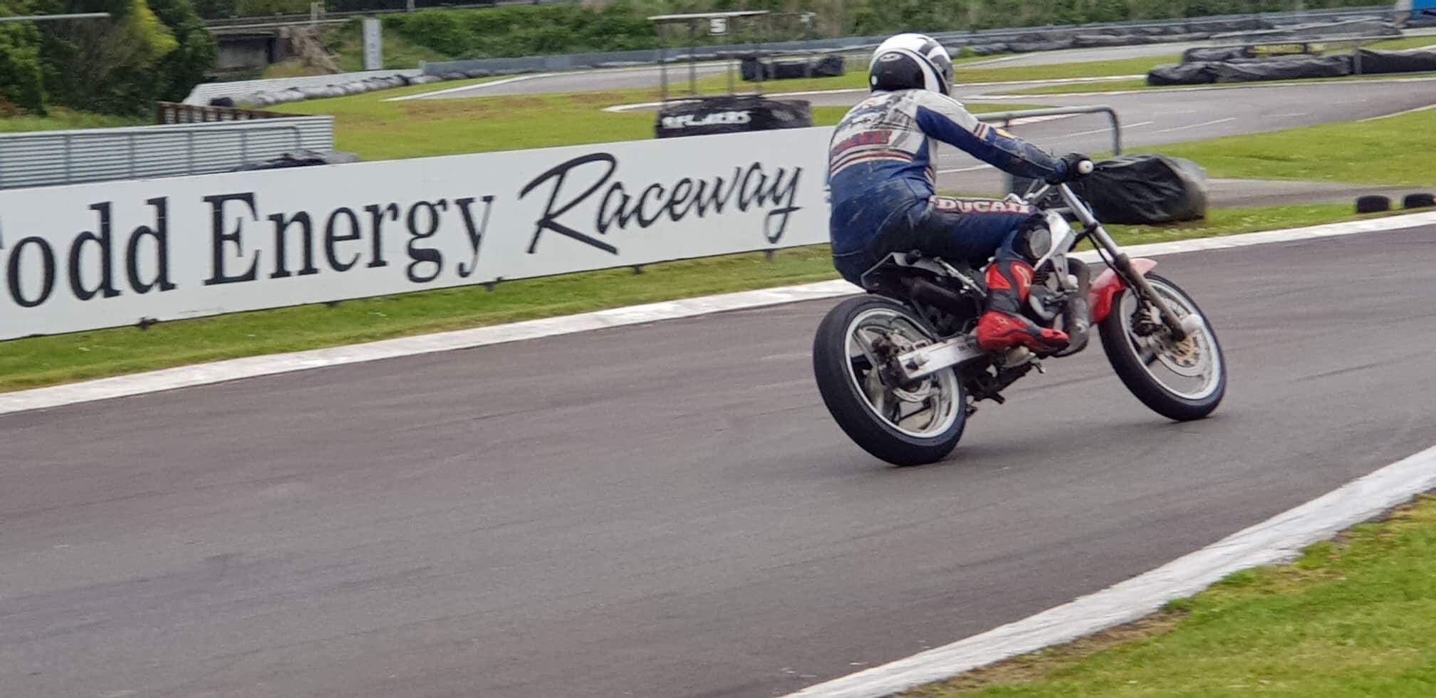
Then we ended up with a little munchkin on the way and decided to move back to New Plymouth. In the mean time dad and my brother were getting into the idea of bucket racing as well, so we approached the local kart club who were quite open to the idea so long as we executed it properly and above all, didn't damage the track or their reputation. A couple of months of organizing and planning and we had access to the track for a shakedown. I hadn't managed to finish any fairings/tank at this stage, so the bike was totally bare bones. It went really well, and fantastic fun to ride.
1 point
-
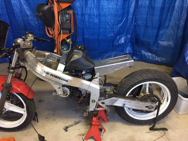
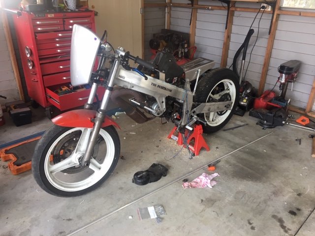
A bit more shed time had a racey light weight tail frame made and Ali-expresses finest pit bike tank mounted. I then started shaping some foam to make a tank cover as the Duke had other plans for the original CBR tank and it was on the northern island. This bike has been treated to only the finest of chinese components. Fork seals, levers, brake pads etc. The brake pads are actually bloody brilliant!
1 point
-
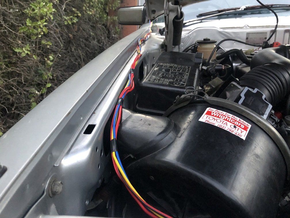
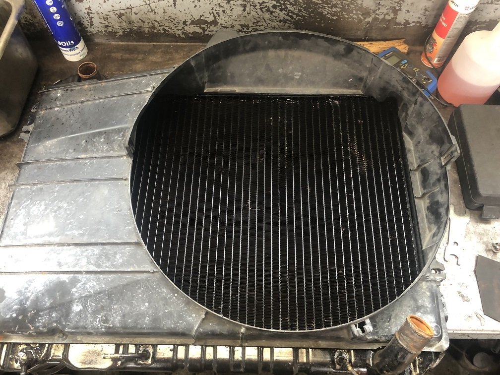
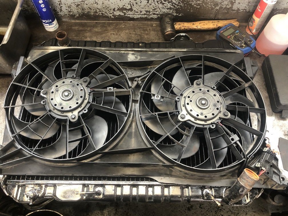
I had the old radiator re-cored by Burnside Radiators a couple of years ago, so no issues there. The 1uz came with the viscus hub fan, but it would be a pain to get a cowling to fit & I'm not keen for it to sound like a van. In keeping with the shoe-string budget I went climbing through the local wreckers with a tape measure & found a pretty bloody close fit. It almost looks like it was made for it! I'll do some minor trimming to fit it on, then wire it in.
1 point
-
Cheers all for attending. Yeah sorry was late notice posting details, but the date is always the same 3rd sunday of January. (kumeu weekend). next new year meet will be 17th Jan 2021, put it in your calendar? Check the facebook link in first post, theres some pics in there already. Also looking to do an autumn meet this year, end of march or easter weekend. This page is usually updated first once i organise a meet ----> http://jap-olds.nz/
1 point
-
Tomorrow! Weather is mint. Theres a bunch of cafes across from the entrance at 'the goodside' so park up and grab a bite/drink. See yas there!1 point
-
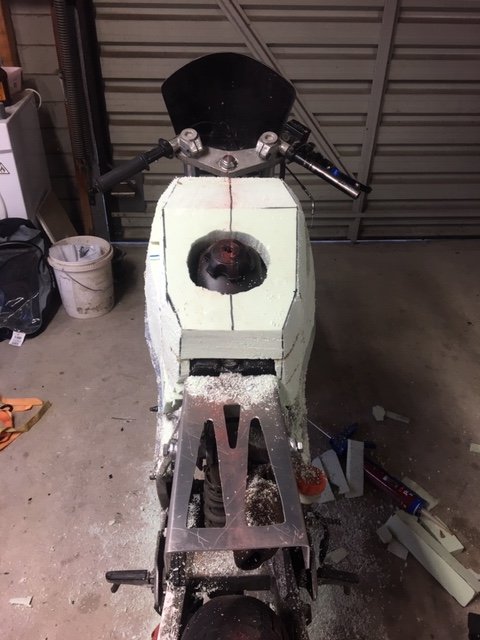
Bought a set 13x6.5 Work Equip 01's. Will refurbish them and then decide if I want to run them. Also scored this off Yahoo Auctions a while back. Has the plugs and also came with some black dash parts. Decided on how to raise the tunnel. Bent the handbrake section up to match the height of where the old gearbox tunnel top piece had to go. Then made up some filler pieces to fill the gaps. Plan was to keep it looking as factory as possible. Had to remake the crossmember as it needed to be built up higher. Used some tube that matched the radius and bent it to suit. Welded in filler pieces. Cleaned up. Next was to make some strips to fill in the sides. Had contemplated making them with the factory swagings, but decided it would be easier to flatten them out and make the strips flat. Then the tunnel to firewall gap needed filling. Made a paper template, transferred it to the steel, cut it, formed it and it nearly fitted perfectly first try. All cleaned up. Up next was the firewall cutout for the dizzy blank cover to sit in. Tried again to make it look factory, which I think turned out pretty good. Stripped out all the sound deadening with dry ice. Have only cleaned off the residue from the passengers seat and footwell area. Pulled out all the wiring as well. Need a F-series diff now.1 point
-
Decided to try and get this thing riding a bit nicer, previous suspension setup was a little soft and hit the bump stops a bit too often, and with the extra weight of a 4age it would of been worse. Went with a set of Fortune Auto's coilovers all around, since I'll end up chucking an F series or similar diff in and I have the skills to strengthen the rear strut towers. Picked up another pair of struts, cut them down and and blasted them. Wound them all the way down and the front ended up a little higher and the back's a bit lower. Might try and get the front down a bit more, to at least were it was. Made a stainless distributor blanking cover. Bought a Flo's upper water outlet, as it looked to be the much simpler and tidier way of doing the cooling system. Needed a RWD waterpump (inc pulley), thermostat housing and a little bypass pipe to complete the setup. And of course with everything else, when you change one thing you have to change something else. The FWD alternator bracket fouled on the thermostat housing, so I got a RWD one from Japan. Borrowed some Flo's 4age to K series engine mounts and made up my own. Sitting in the hole. Had to space the engine mounts out by 8mm, possibly because of the Cusco mounts being thinner than factory ones? Dizzy relocation kit installed, had to cut a bit of a hole in the fire wall for some clearance. Stripped the interior, pulled out the dash, heater, seats, carpet and scrapped off some sound deadening around the gearbox tunnel. Cut a big ol' hole for the J160 to fit. Probably didn't need to cut so much out, but to make it easy to drop out and fit, some extra clearance was needed. Also wanted it to sit up above the sills and chassis rails. Made up a gearbox mount. Added two extra body mounts further back so that it spreads the load a bit. Has heaps of ground clearance as well. The J160 shifter needed moving forward as it lined up with the end of the handbrake. Cut up the original shifter housing and welded it on to some ali tube and 12mm plate. Spent hours on our little lathe turning up the adapter bits. Works mint, barely any flex and feels like it should. Moved it 200mm forward from the Altezza position, 50mm more than the SQ kit and 40mm back from where the factory Starlet one was.1 point
-
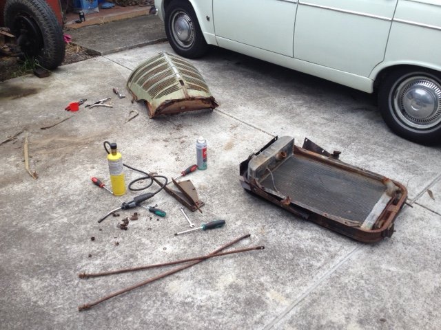
What a slack guy! I've been pretty busy over Christmas, but got a chance to put a few hours into this lately. We finished pulling the nose to bits and sent the panels away for a bit of love. Next step is getting the body off so I can fit this thing in my garage and crane out the engine. The radiator really fought us coming out, it's away getting a re-core priced up. And the rear brakes are also getting rebuilt. Once that's done we should be able to push it by hand, prob for the first time in 20 years!
1 point


This leaderboard is set to Auckland/GMT+12:00