All Activity
- Today
-
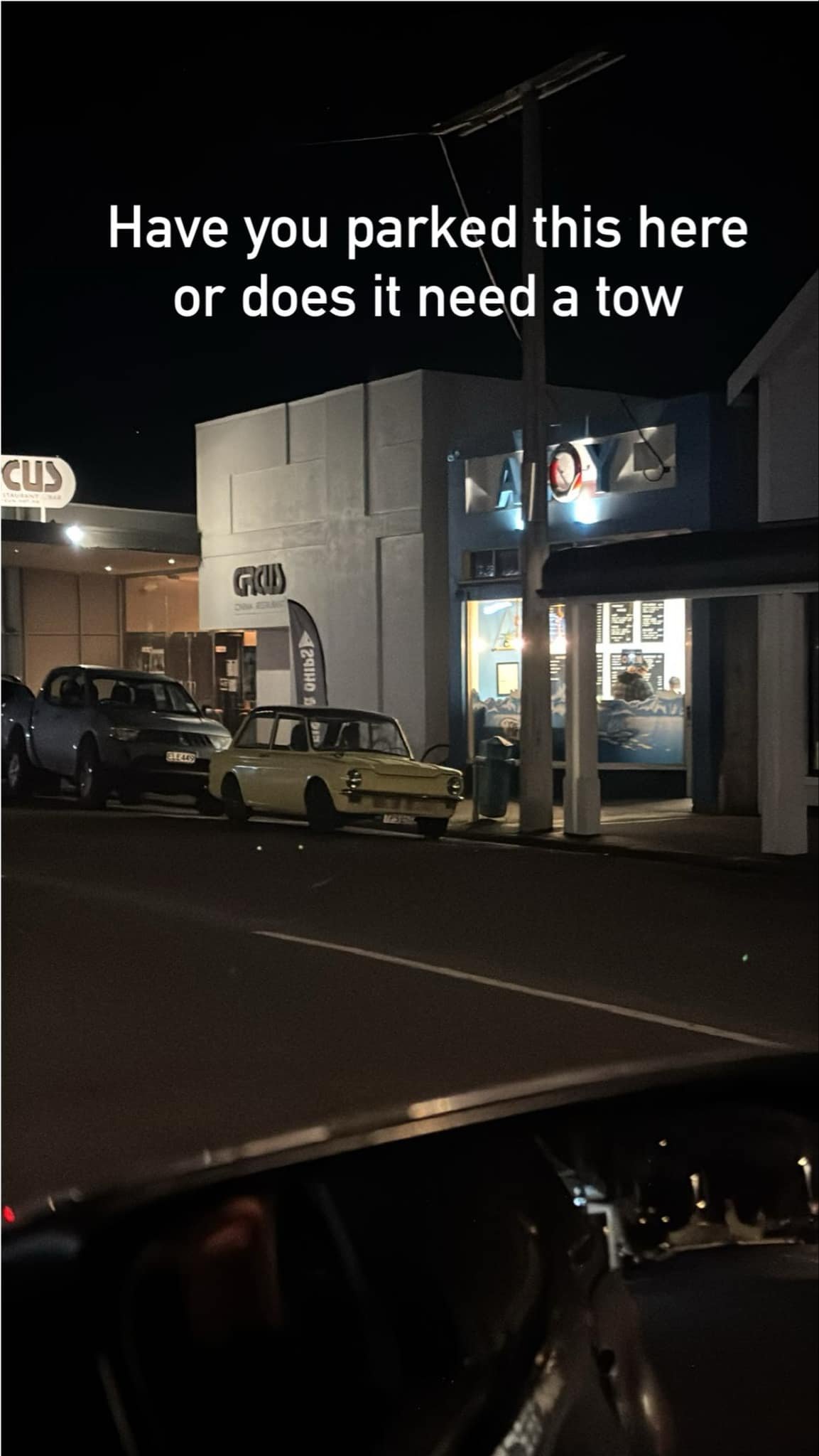
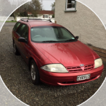
Maiden drive to the chip shop. The vibration comes and goes. I can feel it in the steering wheel rather than my bum so probably the front end. Booked in for first of many LVV checks next week. Got this from a neighbour:

-
 gazza420 joined the community
 -
Can someone please list alternative throttle bodies that fit the stagea m35 vq25dd. I can't find a replacement or a different model one that fits. I have done a lot of research and found plenty of different options for the vq35 and vq25det but not the vq25dd
-
https://a.aliexpress.com/_mOoSo6B There's hundreds on there though, just search tungsten grinder.
-
Fark that looks cool! Got a link?
-
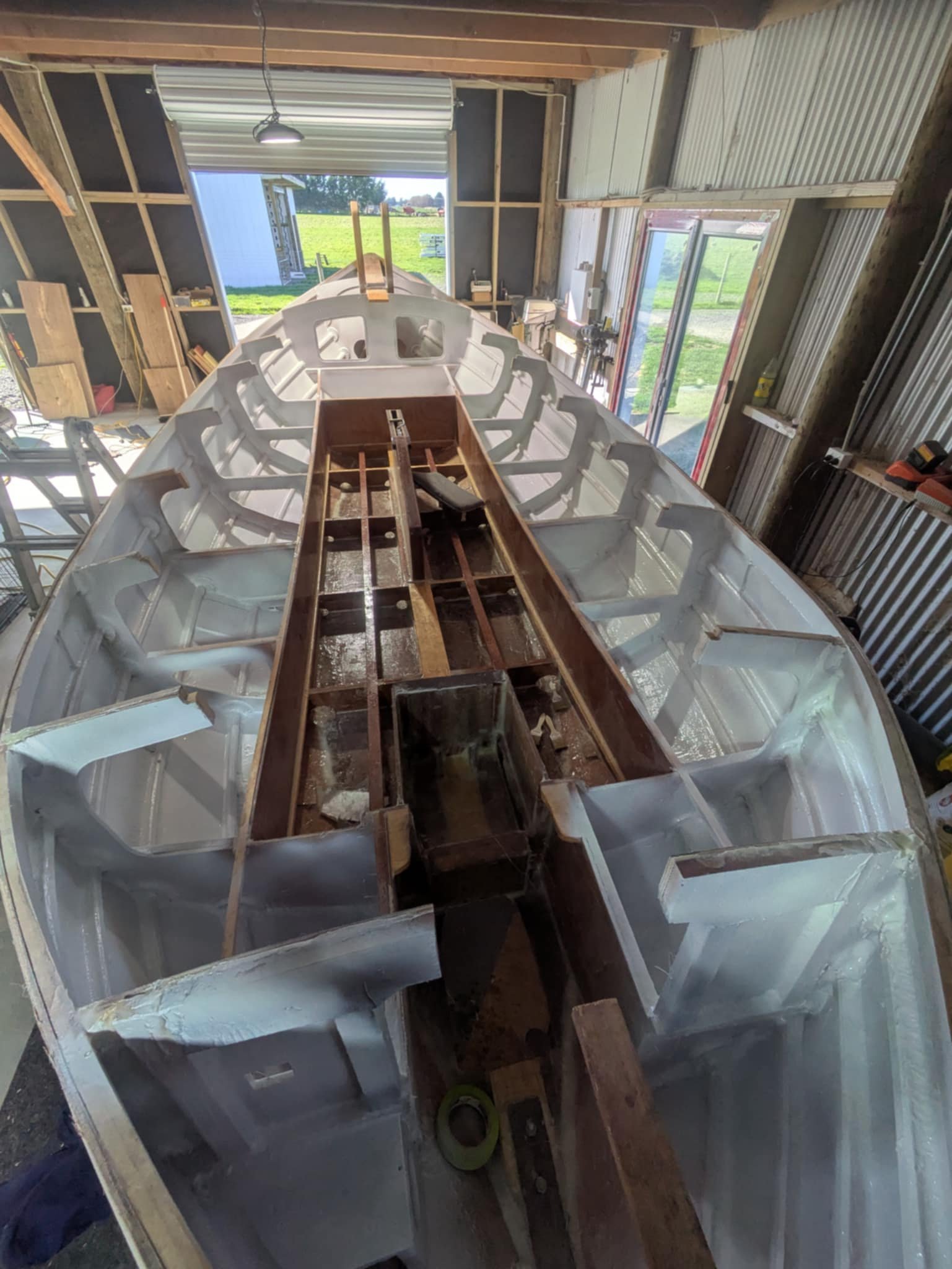
Slapped the first coat of primer on the lockers and had half a pot left over so rather than chuck it out I kept going. So many drips and runs from epoxy coating last weekend looks like this weekend will be spent entirely sanding. Standing back and having a look I think I have to agree for once with @cubastreet that it looks so much nicer open than with a cabin. Maybe I need to revisit to slide over/fold up bimini/tent.
-

Daves new school holden shambles. (Is this project oldschool yet?)
Muncie replied to Muncie's topic in Other Projects
Woohoo!! Spun it to 6200rpm last night log only showed 2 knock events (not audible) in transition and I've got a whole heap of headroom now to up boost and have timing adjustable to go with it. Its ultra rich with weak timing as basically I'm starting from scratch again but I think I've got my head around how to get it set up and make decent power. Cheers HP academy without which my rods would have fallen out a long time ago. - Yesterday
-

Richy's Mid Life Crisis, Season 2, Episode 8 "But I Digress..."
Snoozin replied to Snoozin's topic in Two Wheels
A while ago I updated the plastics on the 350, and had some graphics designed and applied by @Chunky_t via some ideas and inspiration from early 1980s KTM enduro bikes. I also fitted some flush mount sort of LED rear blinkers, as the original ones were prone to being ruined via crashes and were so cooked you could barely see them when on. I just need to sort out a reflector and bodge a number plate light so I can get this WOF'd and go get my full license. This is the result. 2019 KTM 350 EXC-F-43 by Richard Opie, on Flickr 2019 KTM 350 EXC-F-50 by Richard Opie, on Flickr 2019 KTM 350 EXC-F-57 by Richard Opie, on Flickr 2019 KTM 350 EXC-F-74 by Richard Opie, on Flickr 2019 KTM 350 EXC-F-114 by Richard Opie, on Flickr 2019 KTM 350 EXC-F-144 by Richard Opie, on Flickr The #775 is tribute to my very much missed late uncle Tony, who passed away 11 years ago from MND. This was his race number on bikes. 2019 KTM 350 EXC-F-63 by Richard Opie, on Flickr- 94 replies
-
- 12
-

-

-
I would 100% fit a centre lap belt if you have a suitable one to use. (As per the previous discussion) Busting your face up on the dash is (lap belt lyf) is heaps more preferable to ripping your head open on a broken windscreen. (Ask me how I know) Even more so because anyone sitting up front is going to be somebody you give a shit about. (Family, or a mate etc)
-
Just an fyi... Once upon a time, Lance the cert man pulled me up for the centre lap belt bolts in my Navara being the wrong spacing apart. They were too narrow. I had used the wrong holes on tunnel so was an easy fix but the width rule is there to stop anyones pelvis getting crushed in an accident if the bolt spacing is too narrow. So if you do end up fitting a centre belt to the orig holes just double check the hole centres are within the requirements (which I can't remember off the top of my head but I'l check my book later)
-
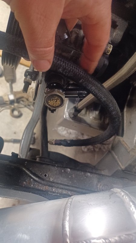
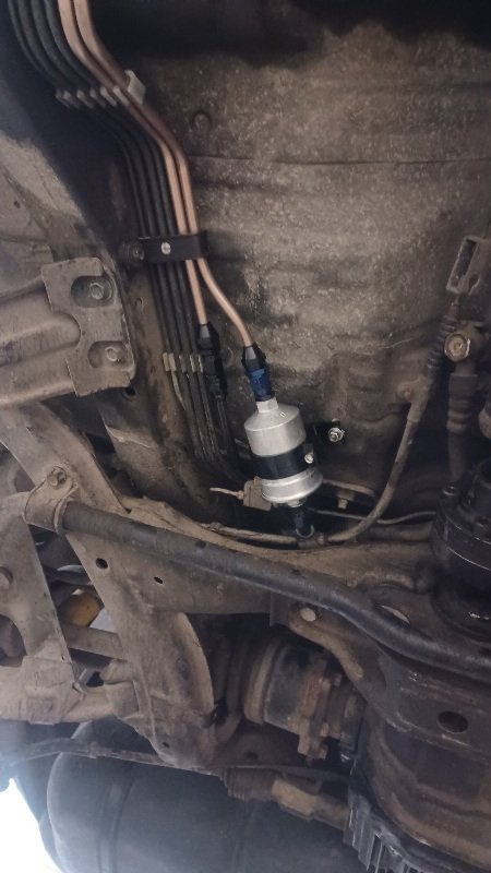
Some work, not many pics. New brake hoses all round. Got some new front brake rotors. Mounted fuel filter under the car. I kind of made my life hard here. I should have dropped the rear suspension when I made the fuel hard lines and ran them right back close to the tank and used some short hoses. But I didn't. I stuck the filter here to make some room in the engine bay Then I cut the power steering hose off that doesn't fit my pump and fitted a hydraulic compression fitting to the tube. Got some hose and fitted some ends. Well, 1 end anyway.... Fuck. So now I'll wait for the mailman to rectify that...
-
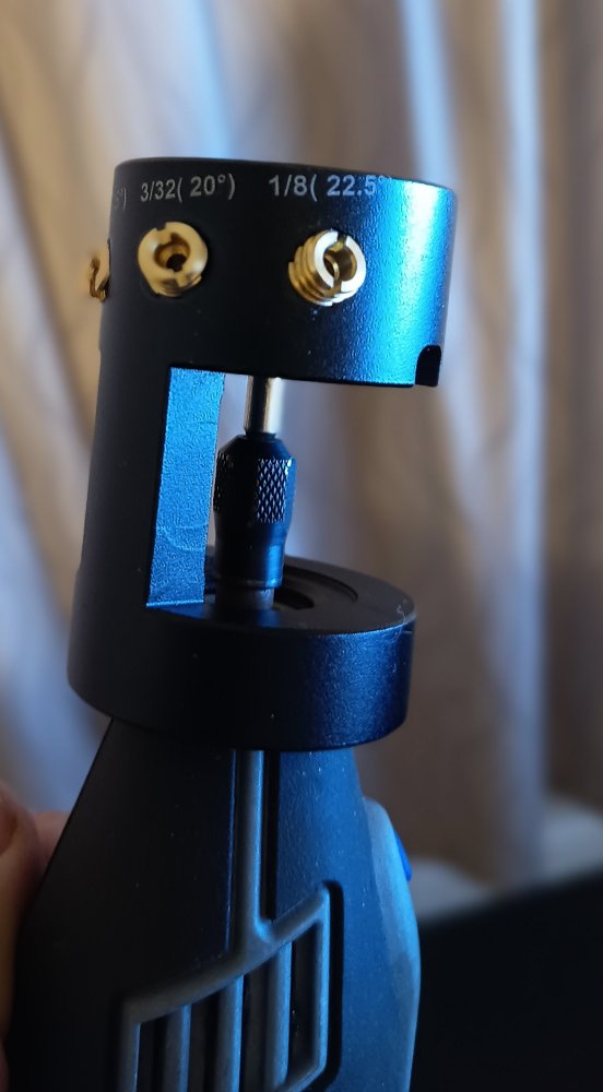
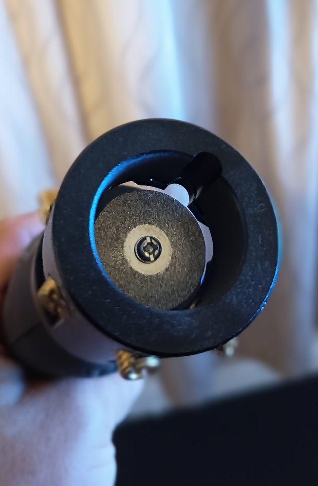
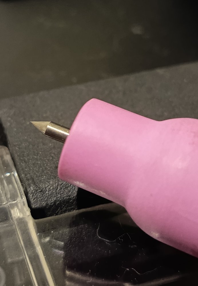
Picked up an AliExpress tungsten grinder Dremel attachment cheap, I'm rather impressed with it! Been using a silica carbide green wheel on my bench grinder for years, that's getting swapped out for a SS wire wheel now as I won't be going back to sharpening tungsten on it in any hurry!
-
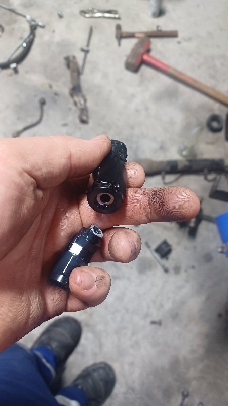
It's pretty butchered tbh. Because I am a butcher. Kinda fucked the screwdriver groove...
-
A life goal for sure. Wouldn't want to show them up
-
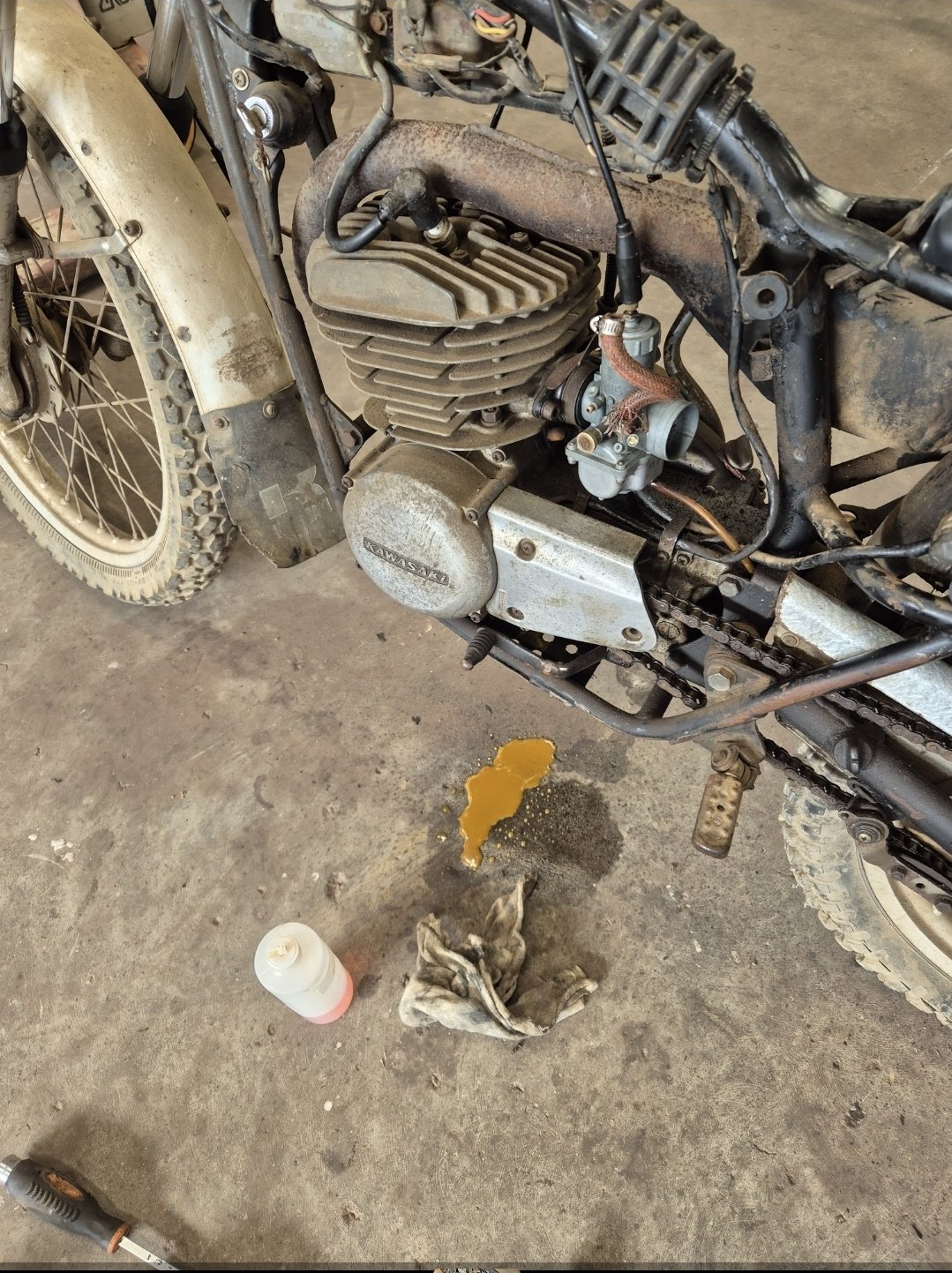
try a soldering iron on the jet, good for direct heat on small stuff to help loosen it up
-
I just happened to be passing and wandered into the workshop after the first run. I was greeted by a cloud of 2t smoke and a grin from ear to ear. Bit of tidying up and you'll be able to join the wheelie boyz in waitara
-
So true. Vintage 2 stroke = OS MVP
-
Yeh the guard lips are untouched so would be a relatively easy fix to get clearance.
-
Photoless updates are pointless *sigh* but she’s been at SprintRE for the last 8 weeks. the new engine looks epic, and is ready to fire up. stopped by today to catch up with them. exhaust is complete and looks so damn good. looking forward to hearing it on Friday . had many curveballs get thrown around so far, mainly with the faulty Wilwood master and the fact that StealthRide don’t seem to acknowledge emails or follow up with warranty stuff. Wankers
-
Will depend on the wof guy Can you give it a massage for a bit of clearance where it's rubbing ?
-
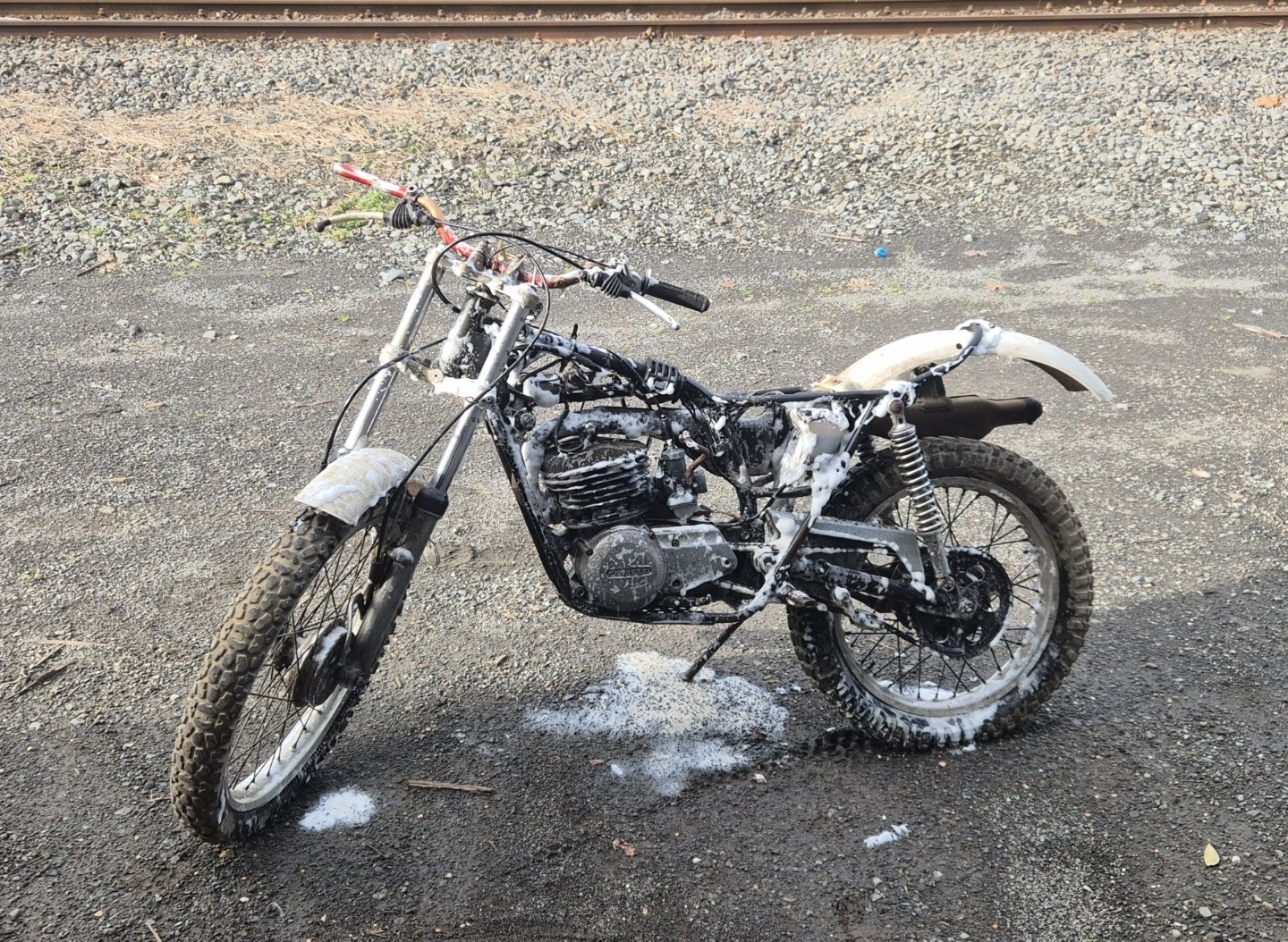
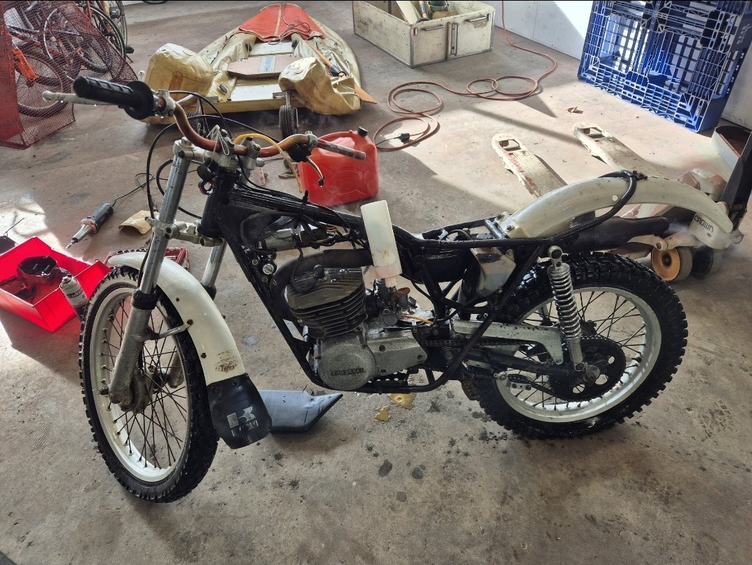
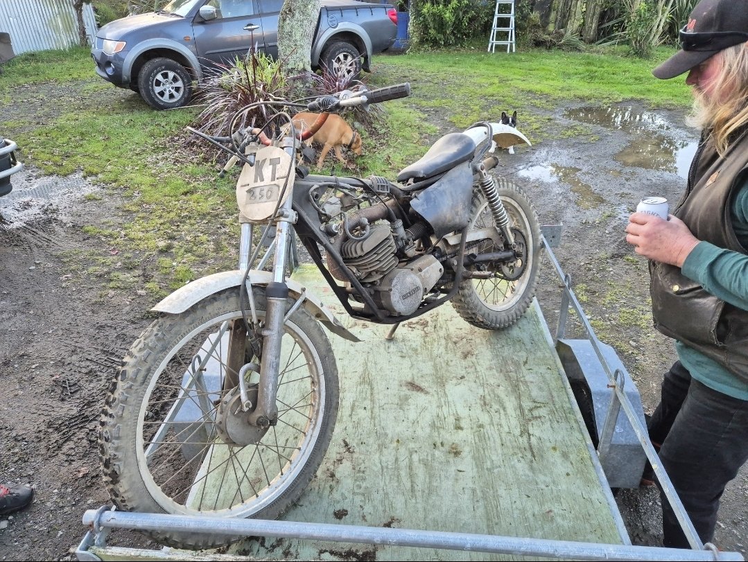
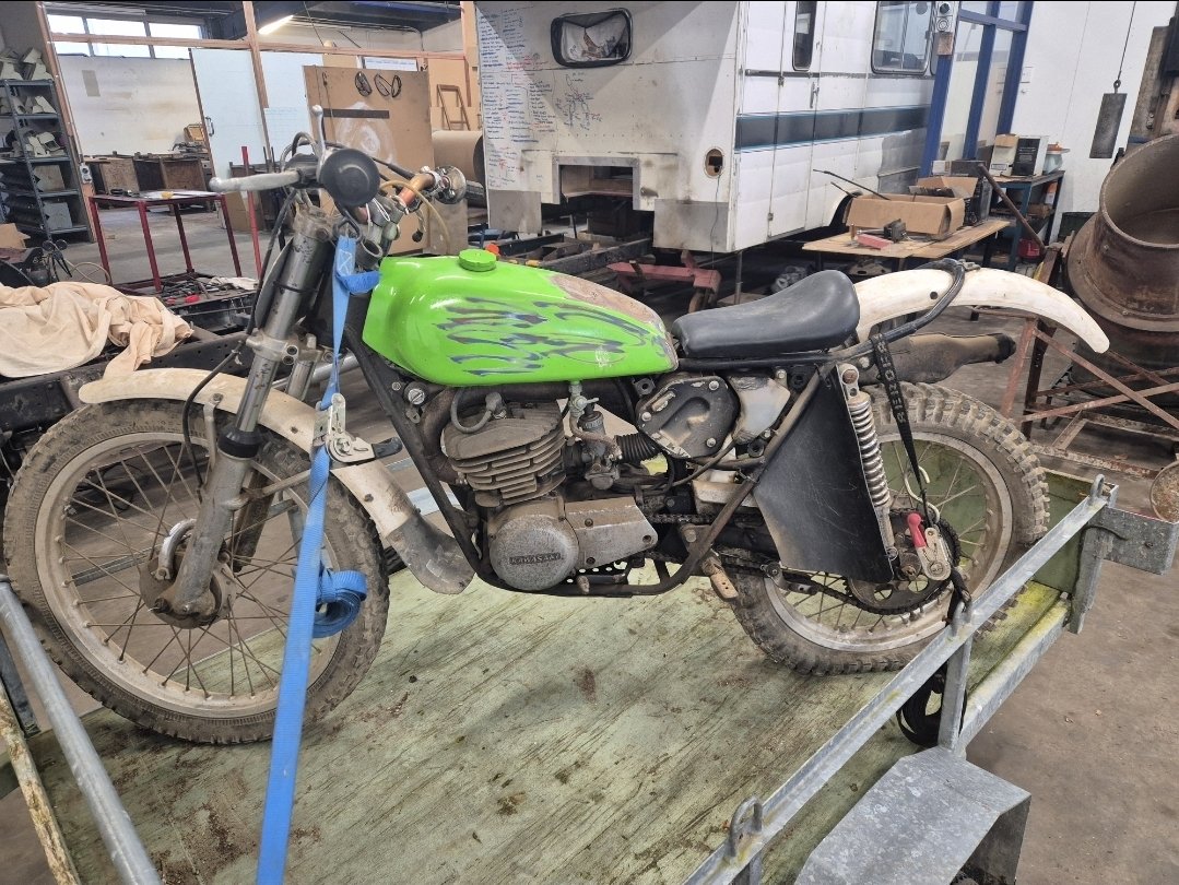
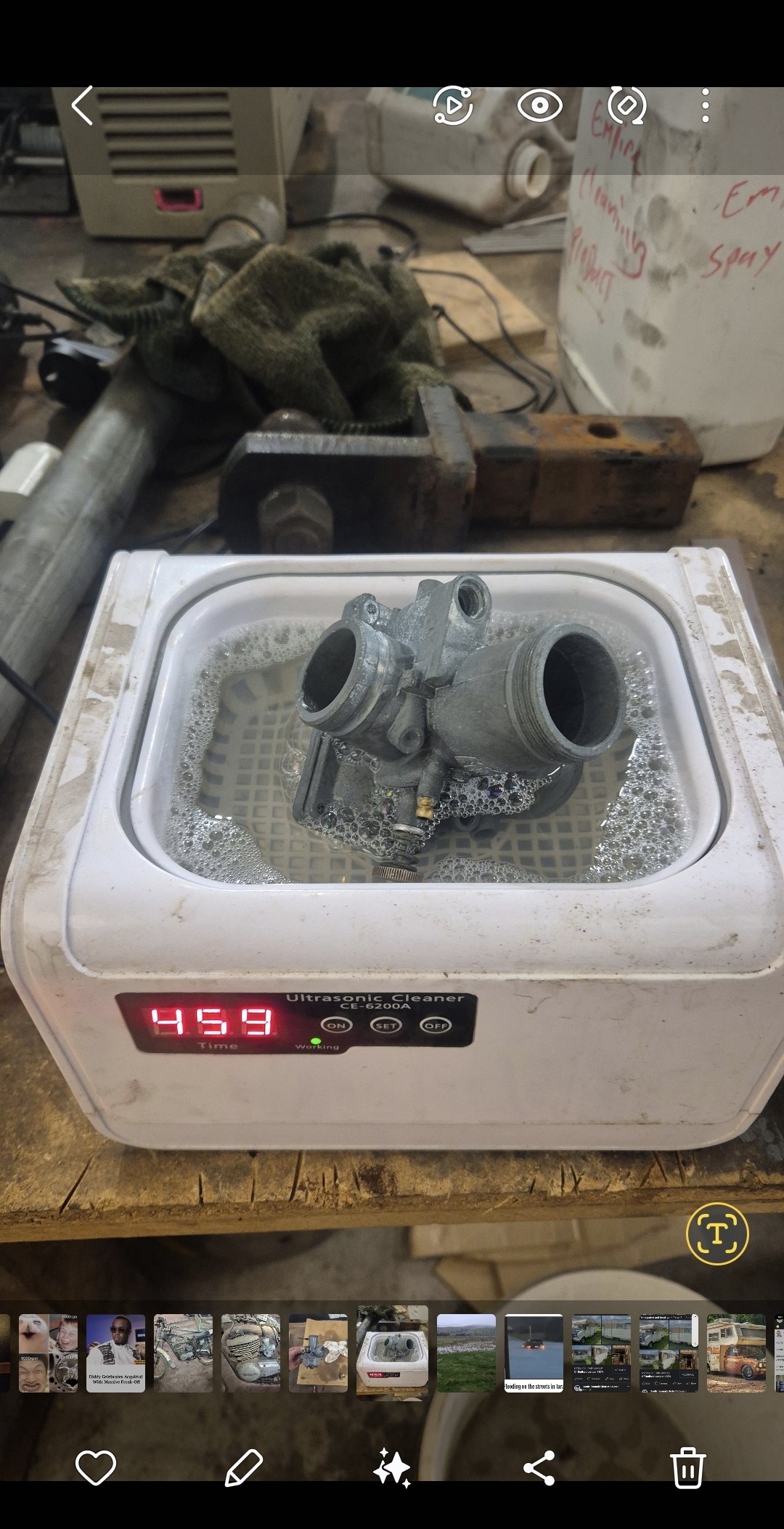
Because nothing cements your status as an OSer like a vintage 2 stroke.. It's either a 75 or 76. They were sort of a trials bike but were sold in NZ as a farm bike as they had a really low first. I reckon it looks cool, could make a great street hack or a board track tribute. But I won't be doing either of those things. Yet. It has a decompression lever on the handlebar for pulling the power back to lug it during trials riding, interesting feature. This one is on pretty sound condition. Missing one side cover but I've already found that. Hasn't run for about 30 years. Leak in petrol tank at the seam by the seat. Was painted in the more modern kawa green but I will find something close to the period correct metallic green for it. I've sourced a decal set too. I pulled the carb and threw it in the ultrasonic cleaner. It was fucking gross but came up good except the idle/pilot jet is blocked, it has corroded in place and I don't think I'll be able to extract it. I could try running a tiny .3-.5mm drill bit through it in-situ or perhaps run 4.2mm bit through the whole jet and try retap. The idle jet is common to lots of things right up to present day surprisingly (kx65 etc). I guess if I fuck it I do know where another carb is. Have soldered tank leak and cleaned rusty shit out. Will swish some rust kill around inside. It's running fucking mint. Pulses really nicely and the oiler appears to work. Next mish is to get tank on and take it for a strap then I'll go over the details. Not sure if it's a keeper, it kinda followed me home and the dude I got it off had other things I would like so flashing some cash for this was a strategic way to get first dibs on the other things...
-
On that note, the ex @KKtrips lobrid prius gets a bit of tyre rub on big woops. Am I likely to face grief come WoF time for surficial wear on the tyre sidewall? It's certified for height its at, and wheels are as per cert plate. Or is it up to the discretion of wof man?
-
Bush lawyer alert!
-
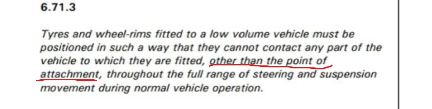
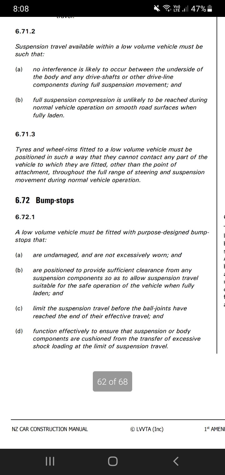
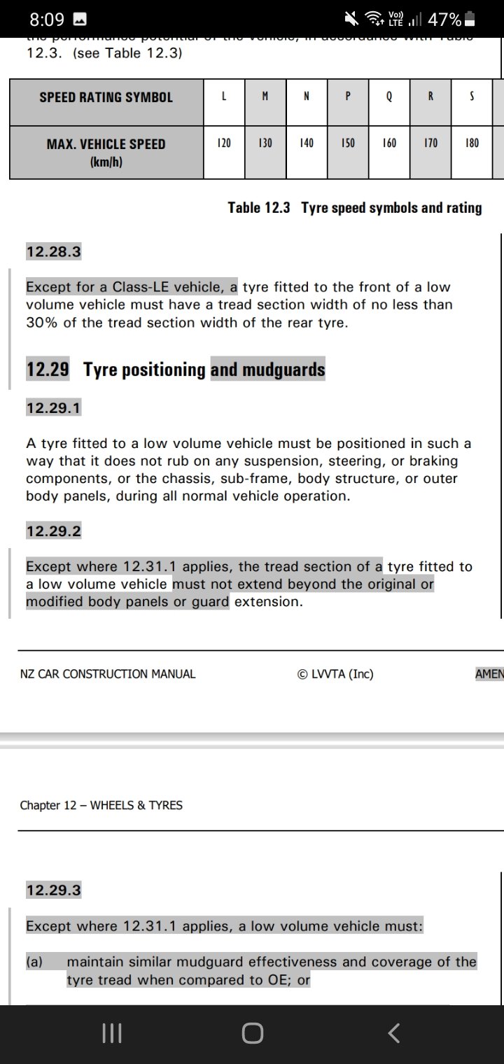
It's in the car construction manual Suspension chapter and wheel tyre one
-
Breakpoints in the rules, just like the daft 6 month WOF rule for pre-2000 vehicles.