All Activity
- Past hour
-
right, so just to recap, the engine, gearbox, ecu, AFMs, entire intercooler pipework, coils, coil pack wiring, crank angle sensor, oil pressure gauge, turbos and alternator all came together off the running car. things that are different are, engine turbo side loom, engine cold side loom, lots of wiring inside the car under dash etc, fuel pressure reg (tried two different ones) boost controller (it now has nothing, just inlet pressure plumbed straight to the gates) and the BOVs vent to atmosphere rather than being plumbed back and both the recerc holes in the intake have been welded up. the fuel pump is different but probably the same (don't ask....) and its wired to run at full 12v all the time, just like the car the engine came out of. i have checked, all coils have power and continuity to the ecu, so do all injectors. injectors all click with voltage. MAFs are showing correct info at the hand controller, as are inlet air temp and water temp. it reads the revs right on the controller, TPS and idle switch both function correctly according to the controller.
-
 I could fill this post with pics of my welds...
 -

Daves new school holden shambles. Oops Rod knock deluxe today.
Muncie replied to Muncie's topic in Other Projects
Have ordered gaskets and ARP head studs from Mace engineering so will get this thing set up and ready to drop in ASAP. I've got a set of spare pair of Ecotec heads that look good but think I'll give them a valve grind and new stem seals. I'd like to give them a tickle in the ports remove some casting marks and reduce the protrusion around the the valve stem. Exciting times but it's been 20 years since I've swapped a car engine and not one with so much ancillary shit sure I'll be fine as long as my garage roof doesn't fall down. - Today
-
 Paulj joined the community
 -
Hi so I’ve got this design1racing supercharger that’s pulleys disintegrated and made a mess out of my 94 Porsche 968 and they don’t sell these superchargers anymore so I want to have a friend at this machine shop make me some however I have no idea what size they were …..anyone help me please!
-
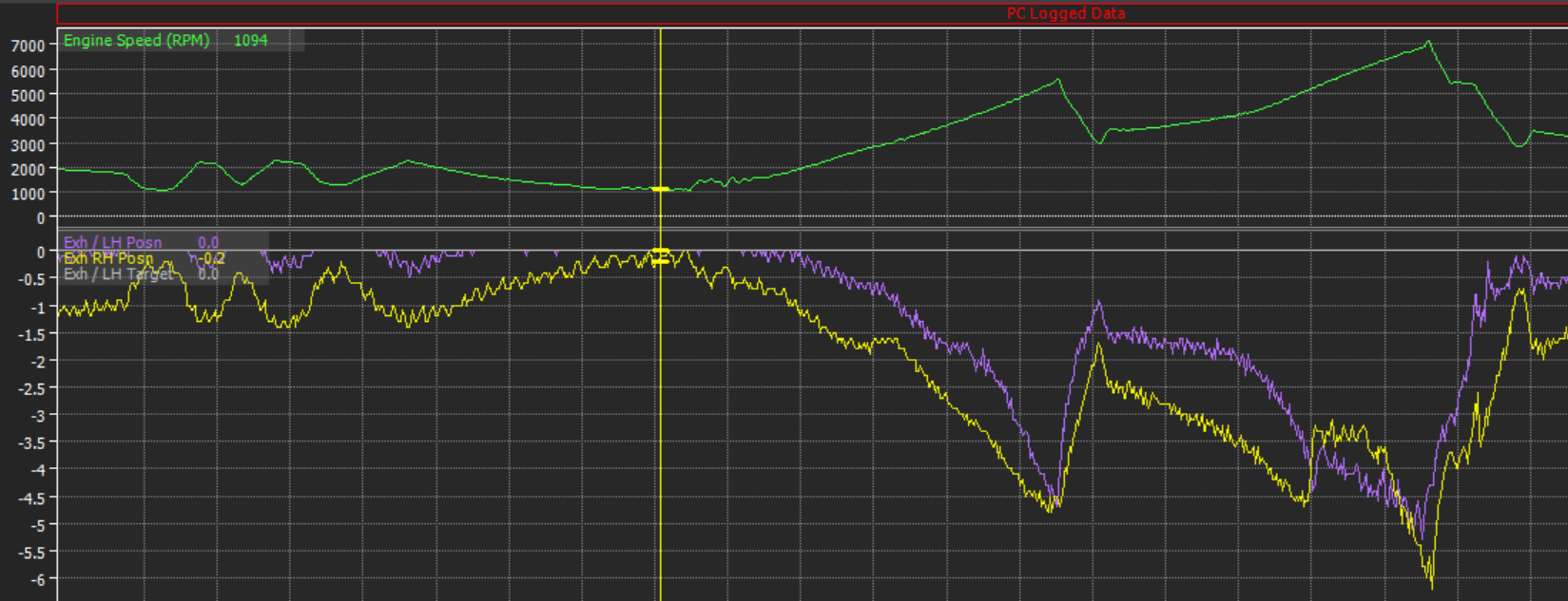
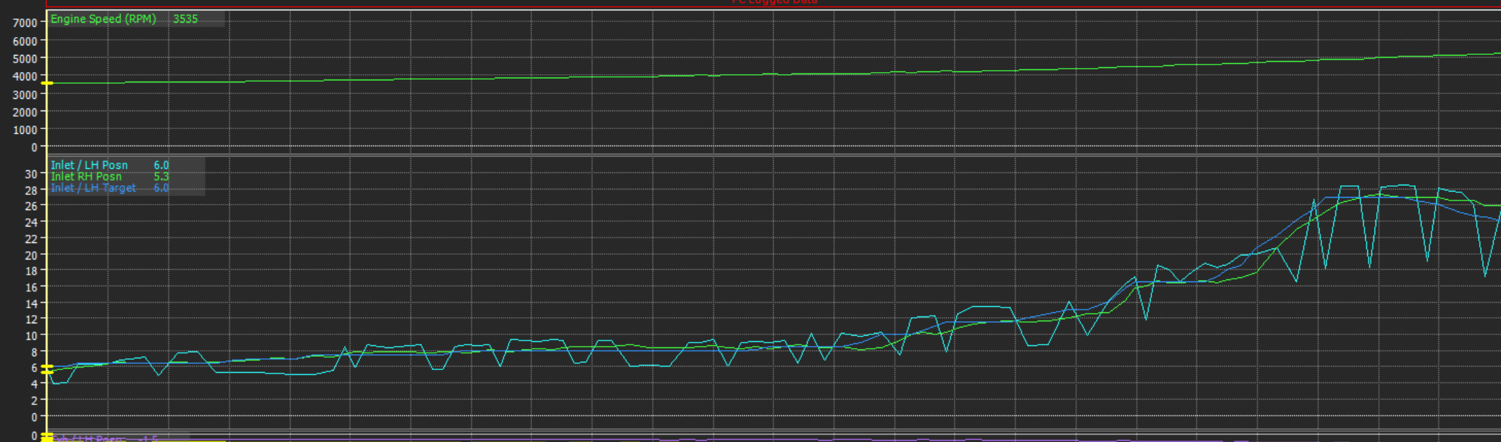
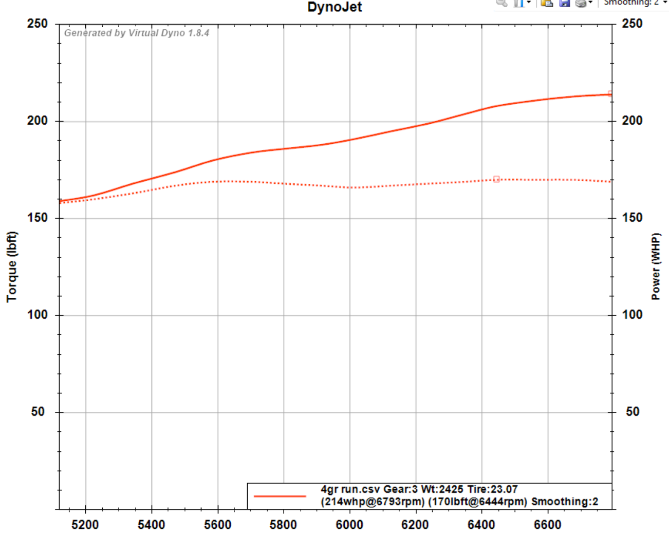
My ethrottle motor turned up, finally! I got everything as well balanced as I could then went for a little bit of a trundle up the road. I have got a few issues to sort out. I've been stupidly sick with Influenza B though so everythings been happening in slow motion recently. The exhaust VVT pulleys end up floating away from target even when there's no duty applied to the solenoid. It's unlikely to be an actual problem as people say it tends to like 10+ degrees of exhaust retard anyway. But it's interesting that there's probably no way I can force the pulleys to 0 degrees at high rpm. It's likely just because of the stiff valve springs, or maybe with a thicker oil it would stay on target (using 5w30 currently) Maybe the chain stretches, or the cam chain tensioner that goes just between intake and exhaust pulleys starts to get pushed in. I'm not sure why the signals are so jiggly but I can add some extra smoothing to it so the PID isnt going crazy trying to get to target. Not a huge problem, but interesting that it is a problem EDIT: A 2GR guy on facebook told me that it helps to set the minimum duty cycle to the solenoid, greater than zero. So will try that. General engine health: Fuel pressure stays dead flat, and oil pressure is looking good, at least to ~7000rpm. As expected, pressure drops off a little when engine is running hotter. But I've got enough of a shape there to start adding in some oil pressure alarm / shut down features. I've got a bit of an AFR imbalance between banks still. However at least now I can trim each motor independently as needed. It looks like part of this is caused by the VVTI PID settings for the intake pulleys not quite being right on default settings, causing airflow differences. Again, this is likely due to having much stiffer valve springs fitted rather than junk PID values by default. Interesting it looks like left and right banks will need different PID settings. I suspect that this is because on one bank, that cam angle sensor is assigned as trigger 2. Then the other bank, its a regular digital input. I suspect that they get treated a little different and with different priority perhaps. It will take a little bit of mucking around to adjust the settings per bank and get them tracking nice, but hopefully not too bad. I didnt do much in the way of full throttle stuff, as was mainly a bit of a shakedown to test a variety of things were okay. With the exhaust leaks at the collectors fixed, the car is sounding MUCH MUCH better. Today is the first time where I've driven it, and come back with a smile on my face because the overall experience was fun and it sounded cool. It will still sound better with an X pipe and so on, but I'm at least happy enough for now. Not much full throttle or high rpm activity so far, however the indicated power figures from virtual dyno seem about right for a healthy standardish engine. More of a health check indicator than full on performance indicator at this stage. Still need to optimize fuel map, VVT settings, and ignition timing. So should pick up a bit everywhere once all that's dialled in. No trumpets fitted at the moment either. The 4GR usually makes around 212hp at 6400rpm and 179 ftlb (at engine) Hopefully we'll be sitting somewhere around the 250whp mark with the big cams in and a bunch more rpm. so, yeah! On the whole, super happy that things are finally getting to the fun stage of the project. Where I can road tune it (to make graphs) and take it to the dyno (to make graphs) and then take it racing (to make graphs) And now I can add the cruise control switch back in, which is bloody excellent. EDIT: I had a reply from one of the 2GR tuner guys on Facebook, who said its normal to need different PID values for each of the four cams. Even when cams and springs are stock. So will just carry on setting that up and treat it as normal that they're a bit wonky currently.

- 132 replies
-
- 13
-

-

Chris' (in)practical daily and every expense spared musso
chris r replied to chris r's topic in Other Projects
Maybe I should cut the other muffler off and since I have the grinder out cut the back half off -
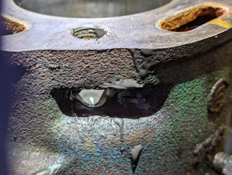
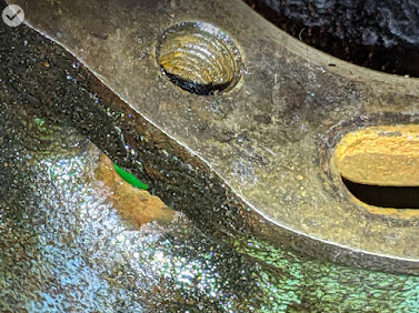
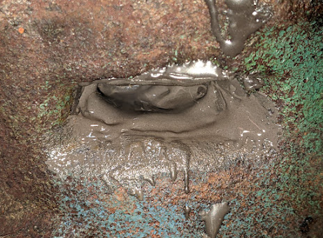
 .. and sometimes bodge'em cars: JB-Weld the water jacket on a car motor? Job done (dusts hands). <still holding fluids in, years later>
-
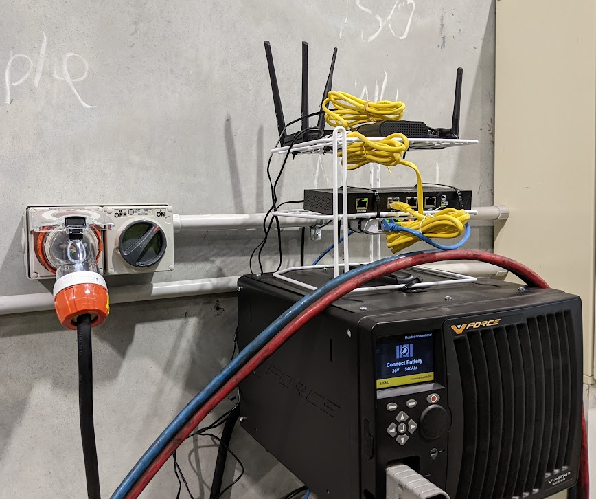
I too play bodge'ems, sometimes with shower racks and network investigation gear:
-
Starting to assemble the front
- 112 replies
-
- 8
-
-
- ms51
- toyota crown
- (and 2 more)
-
Random slightly cool stuff you built but not worth its own thread, thread
h4nd replied to h4nd's topic in Other Projects
Pussy warmer 2.0
-
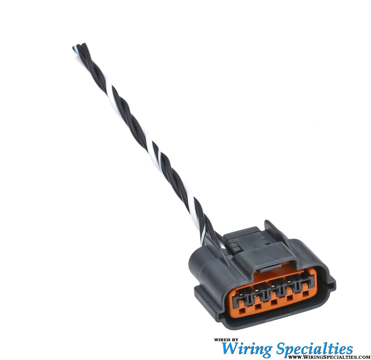
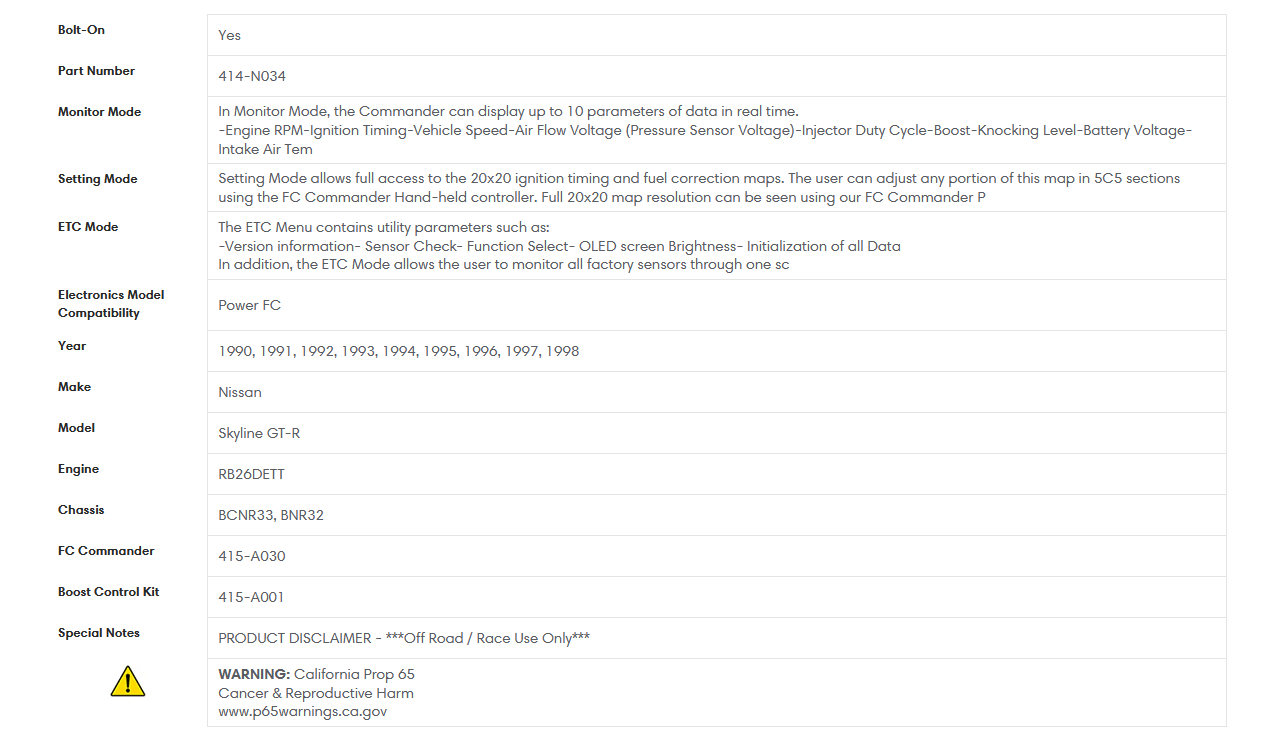
@sheepers if you confirm it is a D Jetro that will help track things down So I am assuming the loom on the motor is the same that was in the old car, in which case the wiring should be correct for the D Jetro Power FC, so possible the Map sensor has died or a plug hasn't been plugged in, or wiring needs to be checked? https://www.sau.com.au/forums/topic/114249-apexi-power-fc-d-jetro-install-instructions/ D-Jetro link https://www.apexi-usa.com/products/power-fc-1989-1998-nissan-skyline-gt-r-r32-r33-d-jetro-map?variant=44318035443933 Someone who sold a complete kit back in the day (help to confirm you have everything) https://www.sau.com.au/forums/topic/404653-apexi-power-fc-d-jetro-to-suit-r3233-gtr/ Some very bad instructions on how to install the Power FC D Jetro with dead pics https://www.gtr.co.uk/threads/apexi-power-fc-d-jetro-install.78356/ Harness option on ebay probably cheaper to make your own tho https://www.ebay.com.au/itm/233738570551?srsltid=AfmBOopkoyW61FGCxFRTSE2IgHv-9CB9dEVR0_izrExs8_FWjBtUyAOU Factory Maf plug looks like this and you would have 2 as the RB26 runs two Mafs, a note the factory RB26 IAT on the plenum isn't meant to be very good and has issues with heatsoak, a few people have commented that is worth relocating https://www.sau.com.au/forums/topic/411652-rb26-air-temp/ Typical Wiring: Pin 1 (No Pin): N/C Pin 2 (Red): 12V power supply. Pin 3 (Black): Ground. Pin 4 (White): Signal wire, sending data to the ECU. Pin 5 (Brown): Not used (N/C) Edit hope this helps
-
I'm pretty sure it's D Jetro. I remember helping diagnose a similar fault on this car maybe 2008 when he byilt the rb30 for it. One of those sensors had failed and it was super rich on 3 cylinders. Maybe the front 3. It was the front map sensor. At a real stretch of the gray matter, I think they were mounted above the fuel rail say between cylinder 2 and 3, and 5 and 6.
-
The bloody triple tree
-
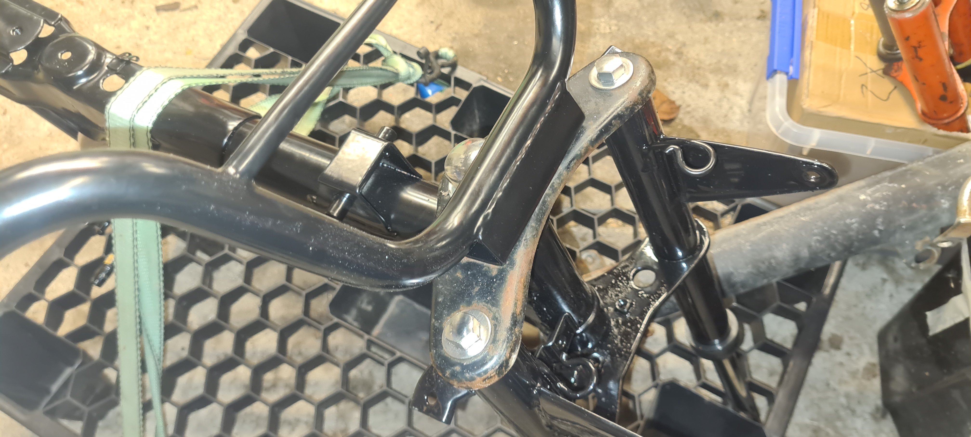
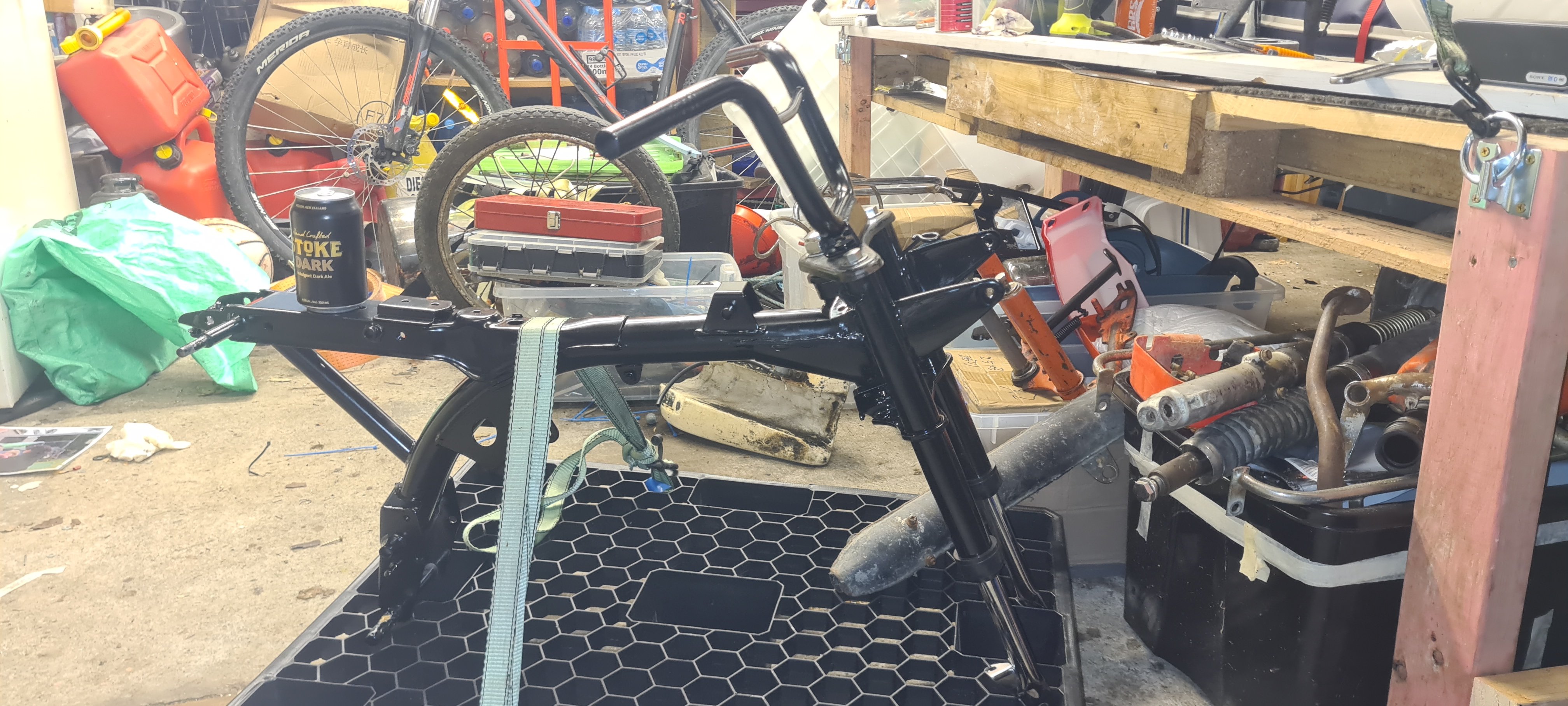
Rebuild Diary 13 July. Picked frame and forks from the Powdercoaters. 100% happy with the service. Added new forks and fitted bars. Triple tree from my new forks didnt fit my old bars, so I have the OG one on atm. Will paint it when it gets warmer. Im only doing one job a night so I dont rush it...
-
 Well that shit is fully designed, engineered and certed by me, so yea maybe.
 -
 No! keep the IP99 storage container lid please
 -
Is your Power FC D-Jetro or L-Jetro The D-Jetro setup utilizes dual MAP sensors https://www.apexi-usa.com/collections/apexi/products/power-fc-1989-1998-nissan-skyline-gt-r-r32-r33-l-jetro-maf?variant=43932592341213 This is the L-Jetro (MAF) https://www.ebay.com.au/itm/153311544187?srsltid=AfmBOopnY4QJParEqwH-MwCa4eXv5BO8FPMb6q6LqMkaEy9f1yCz_ivV Though Id be wondering how does it run if you have a D-Jeto setup and no map sensors Edit: I am assuming you are using the same MAF's that came in the car the engine came out of? @sheepers any chance of some pics of the MAF's installed/the p/n etc
-
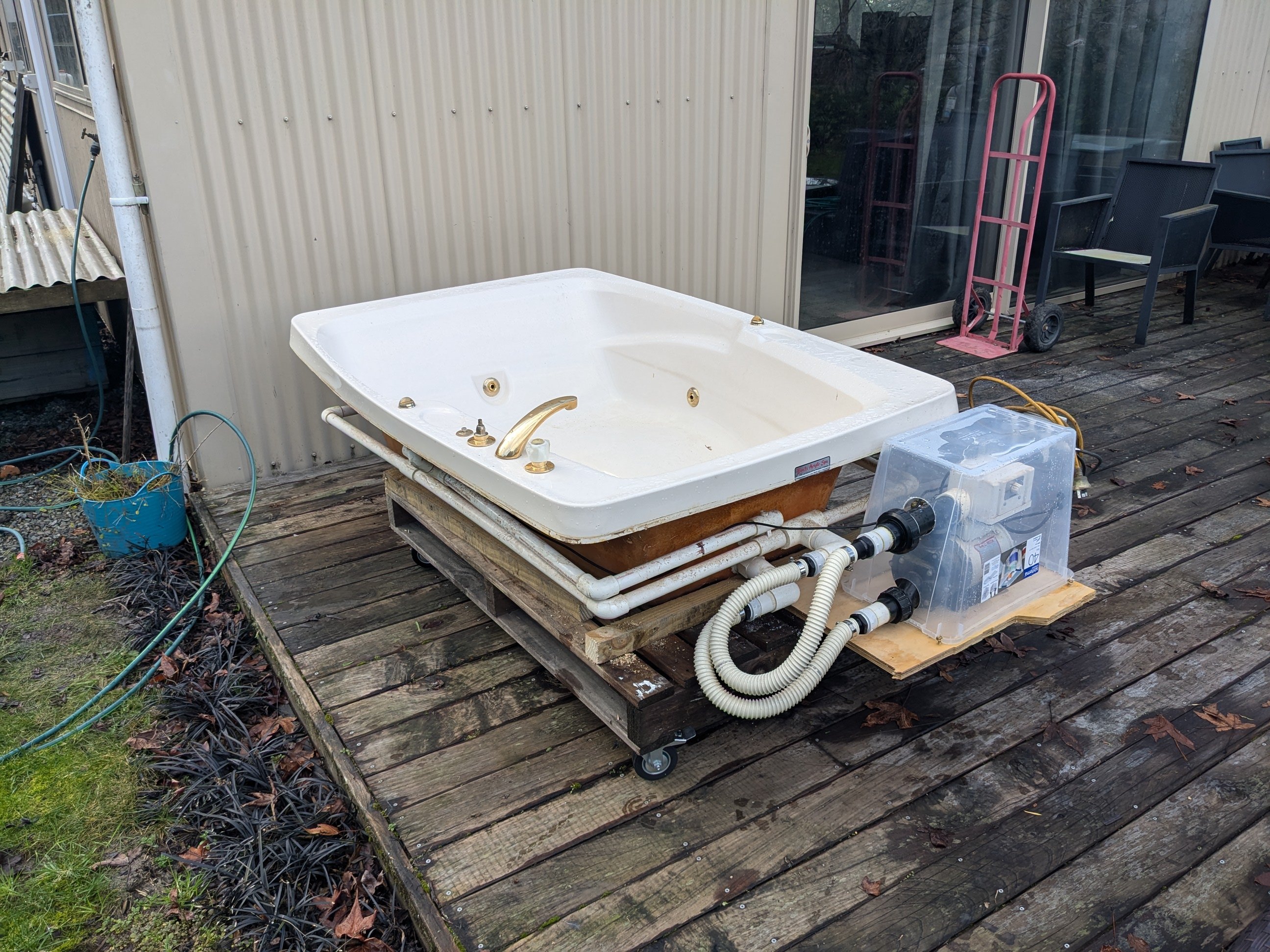
Was going to put this in the random cool stuff you built thread but in reality it is a fucking rough as bodge and probably not cool at all. However I often make things like this for a laugh and probably so do you, so now there is a thread for that stuff. Extra points for repurposing worthless shit. Like this redneck spa I smashed together over the weekend; Unfortunately the gas ran out for the califont in the shed so couldn't try it out, maybe tonight. I might put that pump on its own trolley so it can live out of the rain...
- 5 replies
-
- 16
-
-

-
could be.
-
Standalone map sensor gone missing?
-
so I'm looking at the wiring diag now and the map sensor goes to the dash only. however there is a "turbocharger pressure control solenoid" that my car does not have. im wondering if there is a boost pressure signal in this module that gets back to the ecu somehow? actually, its only two wires so probably not going to be a 0 - 5v signal from that.
-
From memory, I thought it was based on the airflow the AFM/MAF was reading that it calculates against Also the MAF's on these tend to die randomly as well
-
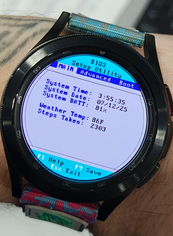
You have an OS on your phone? Flash guy, huh:
-
ive read that, but my problem is finding how the power fc is supposed to receive the boost signal. ill spend some more hours looking at the wiring diagrams and see what i can see.
-
i saw windows xp booted up onto one of those 1" screens. Show off to the consooooomers with apple watches when you boot that bad boy up