
Leaderboard


Popular Content
Showing content with the highest reputation on 16/07/25 in all areas
-
You know it! Thankfully there are some other good variables that you can view/log/transmit. Like the duty cycle of the solenoid. So you can get some feedback without needing to hook up an actual scope. I do have an 8 channel USB scope though, but no point in spending an hour using that, when I can spend only 200 hours writing code to view it on my dash...2 points
-
Hes running the MAF power FC that came off the running engine. I though it was the original PFC from the black car which had the map sensors. Maybe its something simple like the bov's partially open at idle and letting out a heap of metered air. Can you take the vac lines off them and give it a run?1 point
-
Did I just figure out you said you're going to program your car dash as an oscilloscope? 💓1 point
-
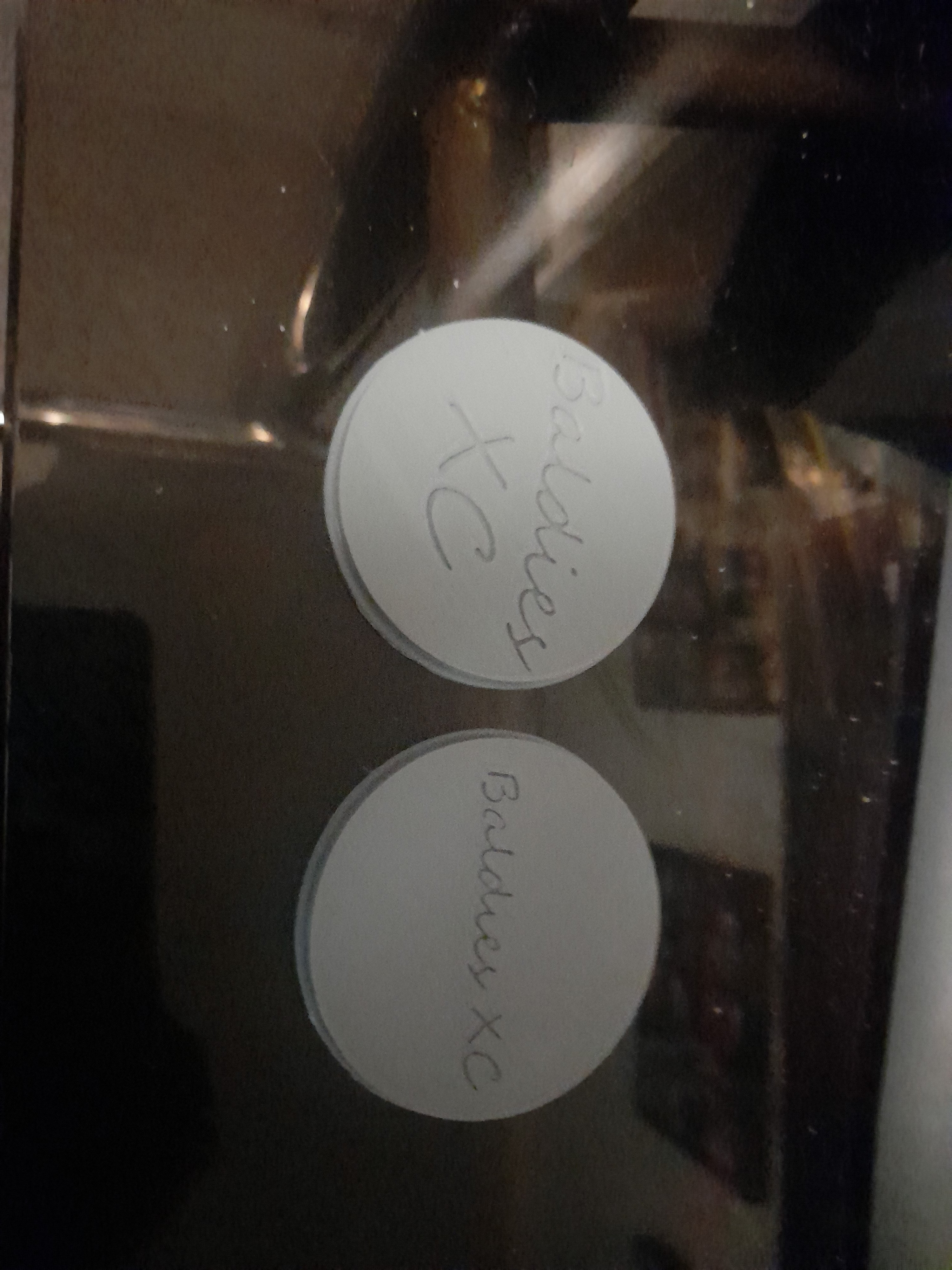
Pulled the dash out of the ute over the weekend, found another skink, got tired of rusty screws so left the heater box for another day. Neither the xd steering wheel i put in the sedan nor the xd wheel in the rotten ute have the centre cap. Started playing with freecad and learning the ropes to suss out some ideas now i have a 3d printer. I prefer the option on the left so far, i think in black with copper inlay should look sweet. Will do some more mucking around during the week.
 1 point
 -
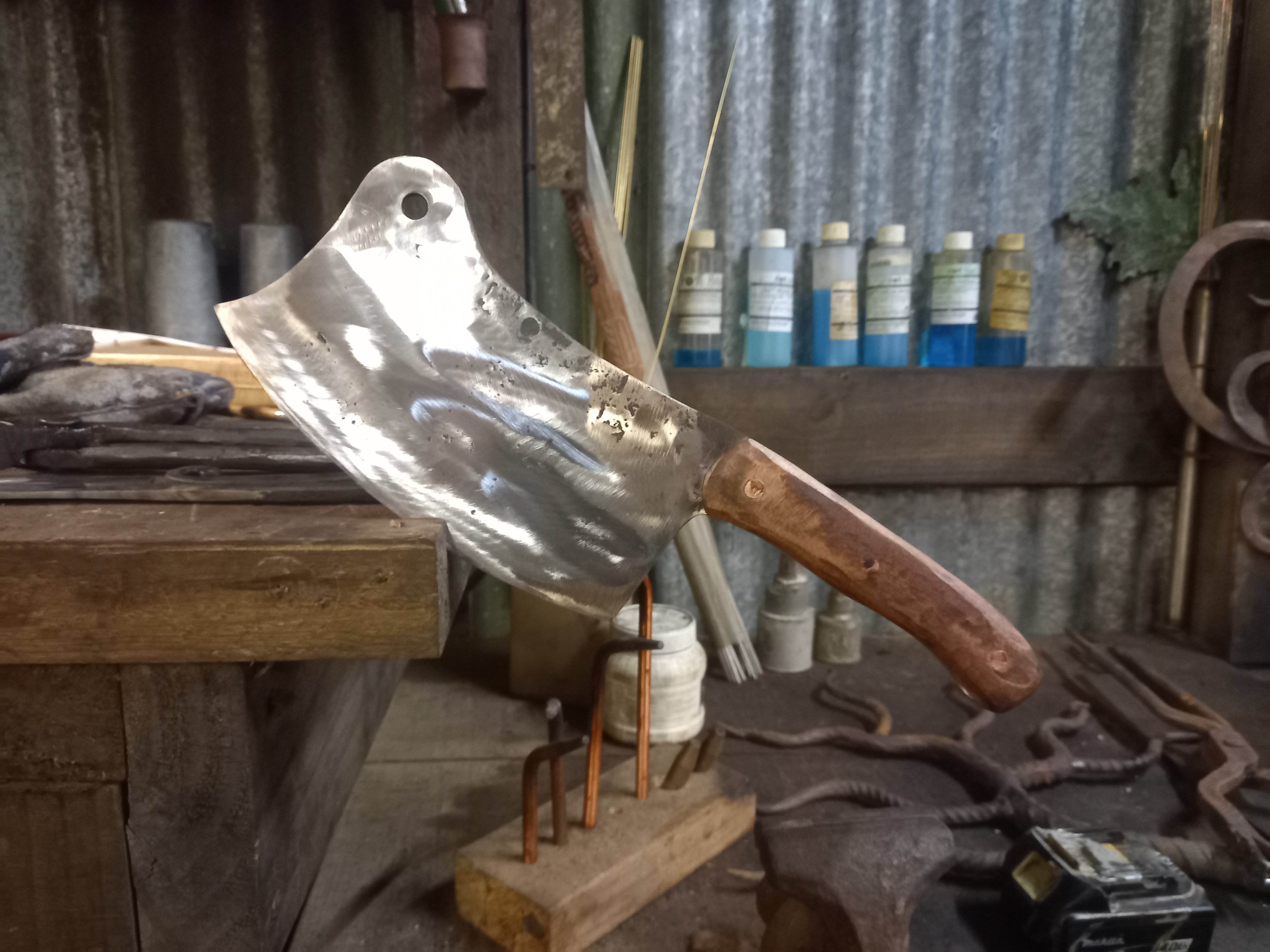
I made this one for a friend, made another 2 but I burnt one by not paying attention and the other cracked as it also got too hot.
1 point
-
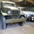
Acquired a pair of Zenith carb castings off a guy in the Netherlands. He finished his 59 a few years ago and had these left over.1 point
-
It's a 2GR and I'm not all that fussy about engine sounds but this sounds clean and F1 like @22.40:1 point


This leaderboard is set to Auckland/GMT+12:00