NickJ
-
Posts
3,973 -
Joined
-
Last visited
-
Days Won
1
Content Type
Forums
Downloads
Events
Gallery
Everything posted by NickJ
-
If you have spare slots in the fusebox, for the love of OCD, use them! They generally use standard uninsulated female crimp terminals, so easy Jaycar are open Sunday https://www.jaycar.co.nz/63mm-non-insulated-spade-connectors-pk-10/p/PT4630
-
Nothing electrically wrong except extreme OCD triggering. If likely to get wet then terrible and if the fuse blows you will hate past self when the wires rip from the crimp as you struggle for grip to replace.
-
I still have some strain gauges left over if you want some to have a play with?
-
This is where my plans all fell to pieces, could rig up the oscilloscope to read the strain gauges fine but the signal to noise was such that I then had to export the wave form and apply software filters to fully interpret the data which was not really in the scope of opensource, easy or cheap.
-
I messed about with them a few years ago to measure dynamic loads and gave up when the costs got out of control Maybe modifying one of the arms to include a commercial load cell for testing might be workable? "Cheapest" option I found for reading a strain gauge was from harvesting loadcell read outs but the read time was 1Hz or static load only range For 1kHz+ read, labview hardware was better, but then in the $2k range to set up. Keen to hear what options come about, must be some diy way to hook them up!
-
If its Fiat and old, then its probably also Lada! https://ladapower.com/catalog/niva-1600/exhaust-system/lada-niva-2101-2107-exhaust-main-silencer-suspension-rubber-belt-detail This is my go to for Lada bits if nothing available locally
-

Advice required: Making complicated brake duct out of aluminium sheet
NickJ replied to Hyperblade's topic in Tech Talk
More than happy to help cnc some MDF forms if thats the path you take -
Advice required: Making complicated brake duct out of aluminium sheet
NickJ replied to Hyperblade's topic in Tech Talk
Yeah/Nah/Maybe Not really an easy short answer cos the variables are huge in composite design, more shape complexity just means more nasty tooling design! With CF, rule of thumb, anything under 2mm precision needs post machining, of course with specific part experience and process/tooling/layup development that can be shrunk but this is a safe start for a one-off. If I was making this for you, I would be going for a sheetmetal solution first to get further clarity on air flow requirements, its a dicky subject so before investing in tooling and materials, getting a good idea the plan works (just heavier) is a good start, Aluminium also gives great track day modification options when things don't work out as planned! In one day I could CAD and manufacture both left and right from 0.8mm Al sheet. In one day of design for carbon i'd be lucky to be unloading the first tool from the mill. As for manufacture, not currently sure who would take this on sorry, most of the suppliers I have worked with would want to be making 100s. Technically I have all the gear here to do it, (mould making, vacuum pumps, ovens etc) but the cost might be prohibitive? Are you still WFH? i've got plenty of free time, happy to discuss in depth over a coffee/beer -
Advice required: Making complicated brake duct out of aluminium sheet
NickJ replied to Hyperblade's topic in Tech Talk
I've designed and had made exactly this from carbon, it can be done and CF is no dearer than the other options, its the tooling, time and consumables that add up... Fiberglass would probably be fine, its the resin system that generally defines service temps, no real structural reason to use carbon over glass either. I love sheetmetal, cheap easy and fast, thats where i'd be leaning as a first off, a diffuser cone to go from the 3d print to feed duct desn't look too hard? Not too hard to CAD, print A3 and then cut out. -
Random slightly cool stuff you built but not worth its own thread, thread
NickJ replied to h4nd's topic in Other Projects
Thats pretty much what I initially tried, down side was it soon warped and triggered a deepdown ocd, off to reinvent the wheel I go... Giz cast adapter -
Random slightly cool stuff you built but not worth its own thread, thread
NickJ replied to h4nd's topic in Other Projects
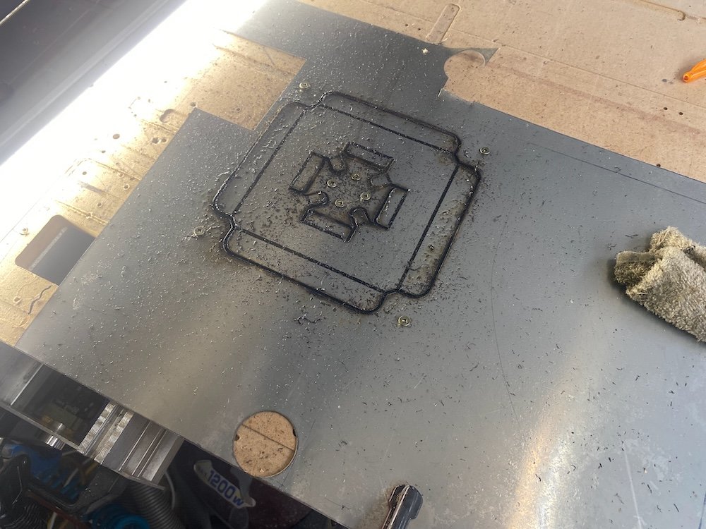
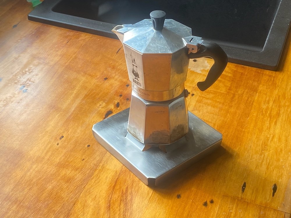
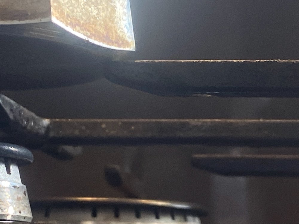
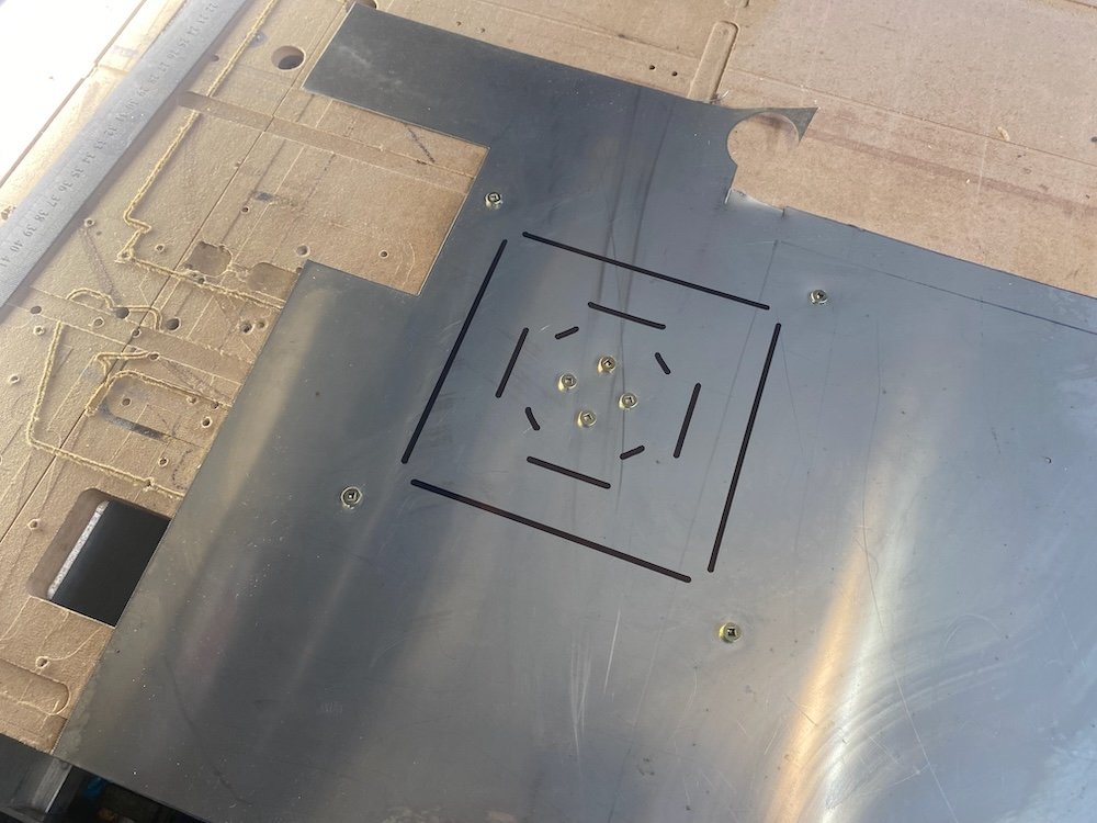
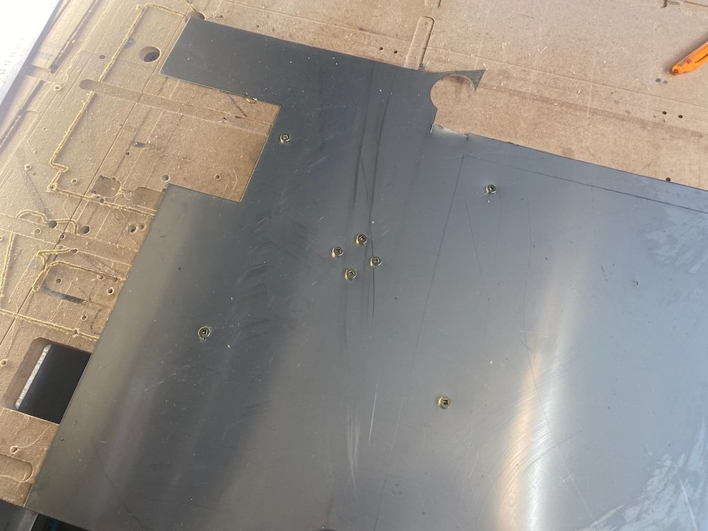
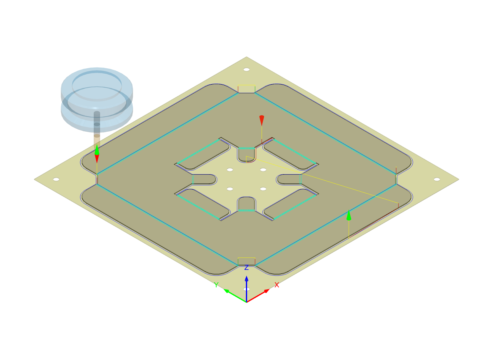
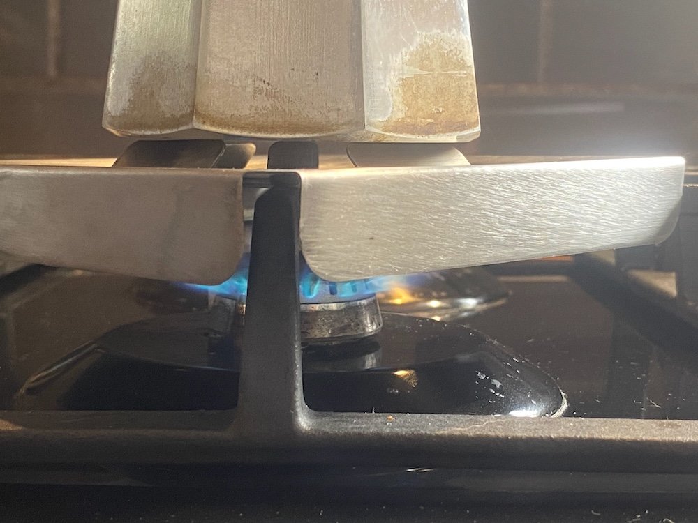
Coffeepot only just fits on the gas cooktop and disasters have struck, a few solutions have been tried but didn't really work, a stainless sheetmetal idea has been floating around in my head that holds the pot up and directs the heat to the pot but with only basic cutting tools I never managed to get far, having just managed to get my cnc router running on sheetmetal, this was a golden time to put a brew on. As @ajg193 asked about my process, I've taken a few photos along the way. First up draw a sheetmetal part and create toolpaths in Fusion, I also make the stock as a seperate body so the machine can place workholding holes in useful places: The idea of this design is the smaller tabs project off the cooktop grill to support the pot while the skirt and larger tabs direct the heat. First machine op, g clamp 0.55mm sheet to the bed and drill 4mm holes: Second op draw fold lines: And finally cut out: This was bit of a disaster, personally I hate working with stainless but I also want coffee, now! Knowing plenty of coolant was compulsory, I got ready with a can of crc, of course this turned into a flame thrower after 50mm of cutting and by the time I hit stop the cutter was toast, I gave it more cutting depth to shift to undamaged flutes and went back to the messy option of heaps of cutting oil, the mdf spoil board was getting pretty smokey by the end of the cut but we got through. Clean off the burnt mdf, add some folds and done: Test run confirms the idea works, but I think improvements are possible. Turns out the tabs didn't quite like the weight once the heat came on and I think a change to the wider tabs could maximise the surface area for heat transfer....... Well, at least the pot won't fall over so easy now
-
I used epotec 408 on some panel repairs to the Defender cos its all I had a the time and its still sticking. Think @nzstato had some fancy aluminium primer for his?
-
Was excited for wof achieved update, bummer for the plug thread
-
99% sure i'll be there, just with one income and the new garage build on, discretionary spending is currently limited.
-
I'm keen as, just fully 100% unemployed at present Reasonably optimistic income will be non-zero by August.
-
Lift arc was super annoying for me as a learner, having a foot pedal and 2t/4t options really helped to let me focus on the task than trying to learn all at once under constraints, I found I enjoyed learning on work's fancy machine way more than persevering on an arc welder with lift tig tacked on. Foot pedal helped learn settings, just added 20% to what I thought and could ramp up or down if wrong. 2t/4t meant with harder geometry I could hold the torch in a few more ways and the ability to back off if settings were way off.
-
Mean, in a kayak + lab? thats him, hopefully you get in touch, really nice guy and good for a yarn or two. Spam sharns: He is bit of a humble legend of the area, years ago there was this thing called the World Heli Challenge, where snowsports folk would hang out in Wanaka to do silly things on helicopter accessed terrain. Rip Curl was key sponsor so for shits and giggles they added a surf day into the schedule, most of the crew were pretty accomplished surfers along with some token pros they brought over, it wasn't a token bunch of kooks being let loose on a gnarly west coast break, was lining up to be a pretty impressive day. We convoyed over to mussel point near Haast where a decent shore break was guarding access to the waves, a number of the crew got pretty beaten up just paddling out with the lucky few having a good time out the back. Without much fuss, Mark wanders off solo down the beach, few of the crew picked up and started asking what the old fella was up to so a few eyes were in his direction, he casually climbed out along the rocks, with precision timing slid into the water past the shore break and paddled out for a pretty decent wave, zero stress and effort as expected on his home break. Some pretty capable pro surfers got schooled hard and were left asking who the old guy was, good laugh for the locals when the reply was just some tradey who followed us here.
-
Correct, belonged to the Sheehan family in Wanaka for many years, their kids both went to the winter Olympics for skiing, no doubt that car played a big part in taking them up the hill. I used to live on the same road, their dog would wander up to our place to sleep on the couch, Mark would come up looking for the dog and also park on the couch, often talking about surfing on the west coast, that car has lived a life of adventure, don't stop!
-
Sorry sun, ol mate Skinner has me sorted
-
Trailer brake master cylinder?
-
I recently brought a ER16 collet chuck for the router so it can fit 1/8" shank microdrills Buy a second to hold the jet and you'd be able to overkill the job without risk of breaking drills or needing good eyesight.
-
Mean! Always assumed those numbers had some meaning but never looked into the details, cheers!
-
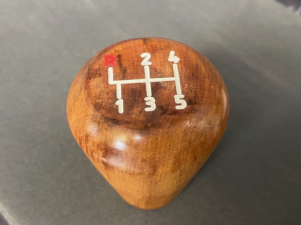
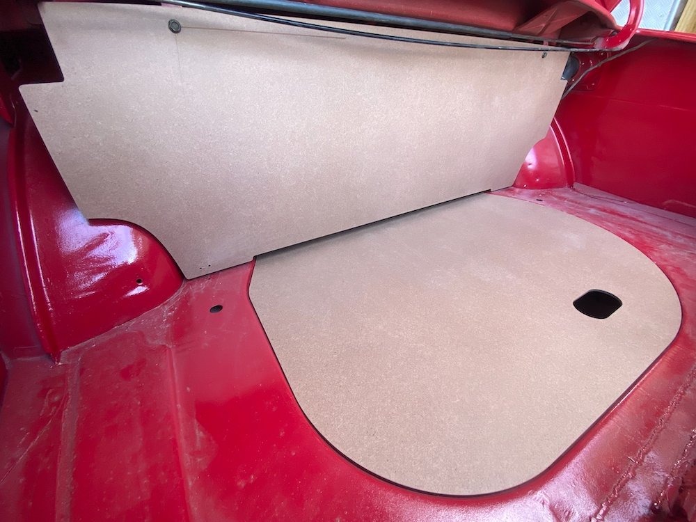
After guessing the shape, dad provided me with dimensions and photos of original boot panels, gave the CAD model an update, grabbed a sheet of 4.75mm hardboard and set about probably the most to factory spec part of the rebuild! Also carved up a gear knob from scrap rimu with the correct shift pattern, scrubbed up real nice with linseed oil too.
- 53 replies
-
- 24
-

-
That place is real cool however..... Last time I did a day mission from chch the river was flowing hard against that bank and straight over the top, could feel the water on the sides was a bit warmer, but no hotpools to relax in, just sandflies to say go home! Cedar flats is probably my favourite in the area, but a 4 hour walk means its better as an overnight.
-
Winter is dry season on the coast, best time to visit, just need hotpools!