Roman
-
Posts
7,219 -
Joined
-
Last visited
-
Days Won
39
Everything posted by Roman
-

Daves new school holden shambles. (Is this project oldschool yet?)
Roman replied to Muncie's topic in Other Projects
The only way I'll win is by firing all my pistons at his car. Likewise, super keen to see your car again! Has had a huge amount of development since last year, keen to see how it goes. 30% more trap speed this year? haha -
Yeah I mainly just need a weather proof space. I can live without power lights etc for now. As I just need to be able to take my motor out to work on the firewall etc without everything being exposed to the elements. (and animals) So hopefully not too long to go. All of the wiring is done, I need to test some things like lights and indicators and so on. But the stuff needed for drags at least is pretty easy. All of the engine wiring is sorted, all of the sensors have been tested and calibrated. Alternator works, and all that. That video you posted is interesting, because to me that KF motor sounds more like a high strung 4cyl. I guess the thing with a V6 is that if you have even firing order separation on each bank. (So 60 deg V6, not 90 deg like DTM motor) Then you have 240 deg of separation between each exhaust event on a bank. Compared to 180 degrees with a 4 cyl. So the exhaust can sound a lot different because if you had a 6-1 (or effectively 6-1) you've got 120 degrees of separation so it will sound higher pitched. But then if you ran totally isolated exhausts on each bank, or the pipes are really uneven. It could also keep its "240deg" sound, and sound like a pair of 3 cyl motors driving in unison instead. And then there's the effect of having an unequal length between each 3 pipes too on each side. I guess a good comparison, is that a Subaru "boxer rumble" comes from only the pipe layout, not uneven firing order or anything. Yet sounds wildly different to most other 4cyl motors. If you put an equal length manifold on it, they sound just like a normal 4 cyl. Compared to a 4 cyl, there are lots of different ways you can affect the pipe interactions on a V6. Can have a 6-1 manifold, long primary, short secondary 6-2-1, Short primary, long secondary 6-2-1, Separate 3-1 with long or short primaries. Then all of the ways that different mufflers can affect the sound... and what cams you have. Then how much noise comes from the intake. So it's probably a good thing that nothing is set in stone in terms of how the motor sounds. As I'm not expecting it to sound particularly pleasant, or even go particularly well on first iteration. But at least when the motor is going, and the car is driving. The fizz level ramps up, and doing the iterative changes and testing is the fun part for me.
-
Damn I envy your clean tank, haha. Surely a 4.3 final will be pretty good once the blower is on?
-
Honestly it could be anything ranging from really nice, to absolute dogshit depending on exhaust and so on. Might take a few iterations of the exhaust to get it sounding nice. It's hard to say because none of the (3500cc) 2GR people seem to run ITB or rev out very high, and I think thats what will define the sound on this. Virtually everyone with the 2500cc version leaves them unmodified, because it's too hard to mod the direct injection engine. Seems that equal length pipes is the key to nice exhaust sound though, so hopefully manifolds will help. If the sound was hilariously out of place for a Carina, somewhat like below. That would be ideal. (The Alfa 155 DTM has a 2500cc V6 that they run to 12k rpm) However it might end up sounding like lil johhnys straight piped RB20DE swap INB4 @xsspeed tells me that's a good thing
-
Exciting!
-
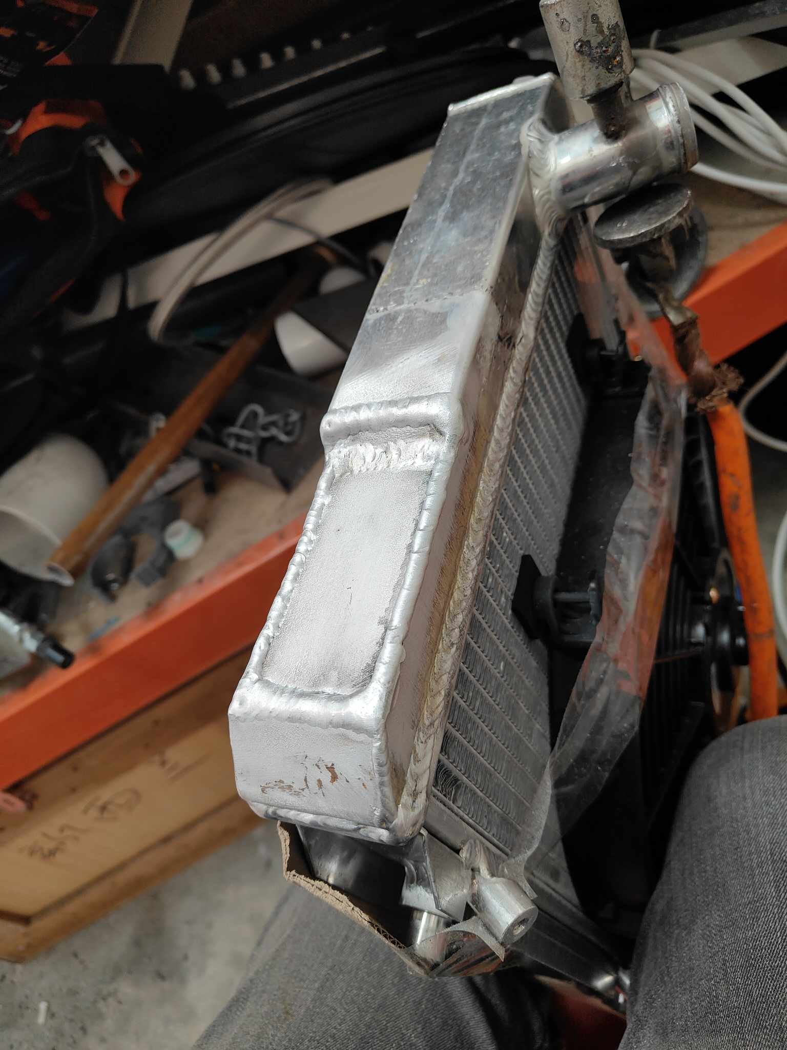
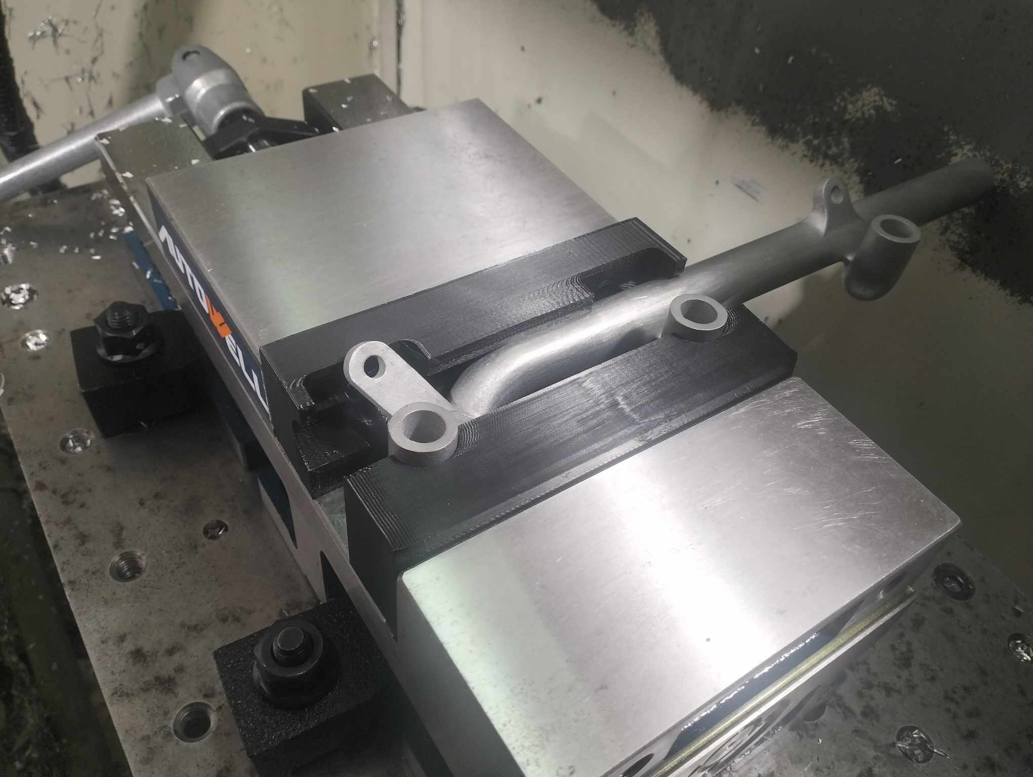
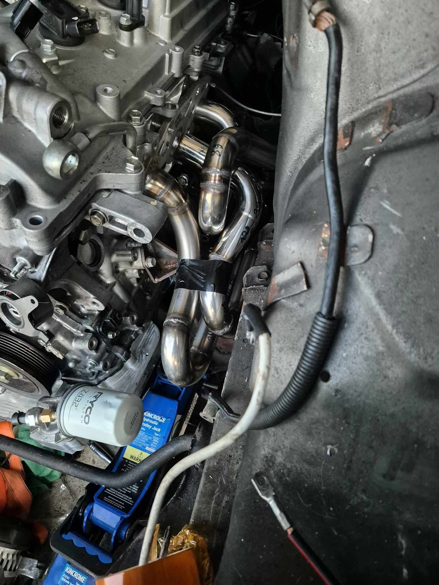
OS 2024 DRAG DAY QUEST! I am running behind schedule of where I'd have hoped to be by now. The last month has flown by without much progress. Due to concentrating on getting my new garage up and being away from home a lot for work. Some other people have helped me though which I am very grateful for! @flyingbrick helped me with getting the radiator patched up properly, many thanks! Now it will fit between the rails and hold water. I'm not sure if he is a member on OS but Dan from Taupo helped me to machine the fuel rails. Although I thought it was a cool idea at the time to make these a derpy shape since they are printed. I guess I kinda forgot that it would be a total prick to hold them in place later on for machining. Dan desinged some soft jaws which I printed. Then he drilled injector holes to correct size, and tapped the threads for the end fittings. Thanks Dan! Much appreciated. Hindsight: I should have added a hex shape or some flats onto the very end of the rail, so there's something to hold onto with a spanner when tightening the end fittings. I've sourced one of the tiny dual diaphragm KE70 brake boosters and master cyls, this will give me a heap more clearance to the drivers side bank. I wont fit this till later though. As per usual my scheme for the extractors on passenger side didnt quite go to plan. There just wasnt enough room for the 3rd runner to work nicely. without hitting the chassis rail. So I have a bit of a dorky shape on 3rd runner but if it gets me going then thats cool. They're all fairly even lengths. What's left to do, to get to the drags? -Finish building garage -Finish extractors -make rest of exhaust fit -fit mufflers -hang exhaust -make battery box / battery wiring -wire up radiator fan -redo fuel lines at back of the head -add charcoal can and extend the line from under the car -Make top and bottom radiator mounts -Test start up? -Test drive? -Pull motor and box back out, crossmember out -properly weld engine mounts and repaint crossmember -Remake firewall -Swap to KE70 booster and MC -redo brake lines I've got 8 1/2 weeks to get all of the above finished, put some miles on it, shake out any unforseen issues, and get a tech inspection. So I'm kind of at the point where it's doable, but I need absolutely nothing to sideswipe me between now and then. Which is highly possible. Kind of exciting. See how it goes!

- 130 replies
-
- 40
-

-

-

-
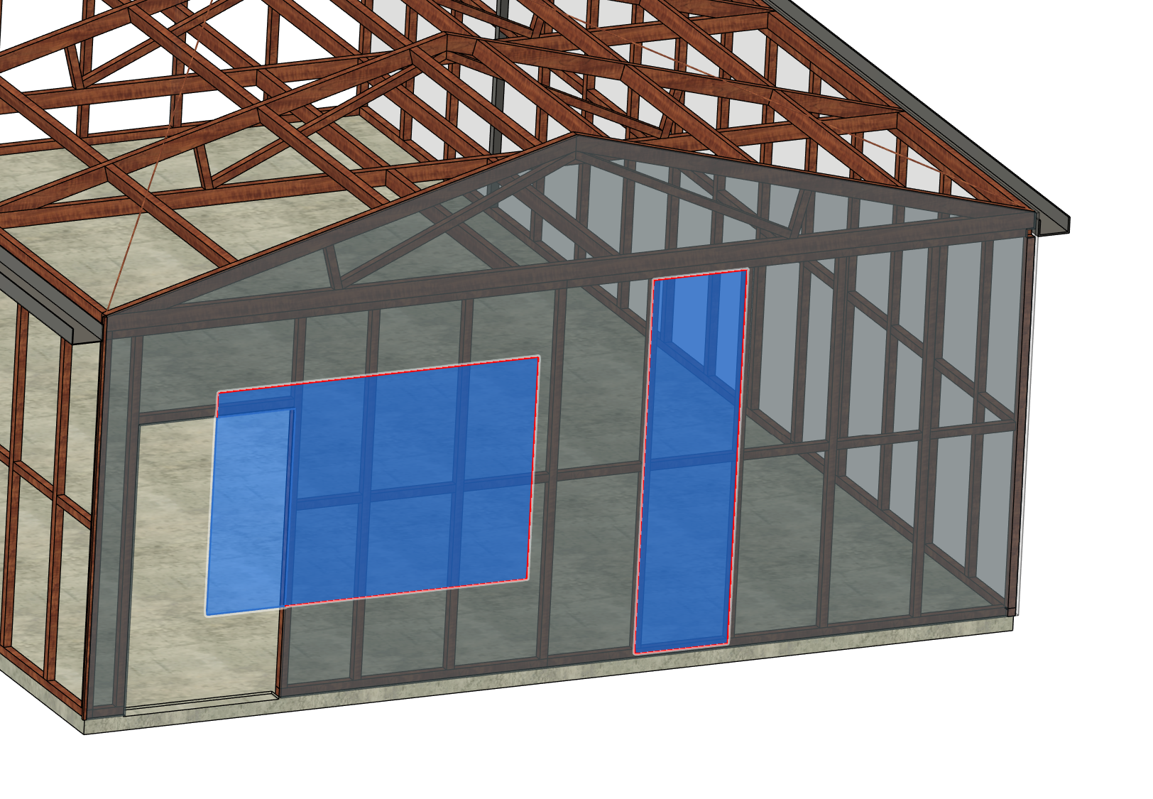
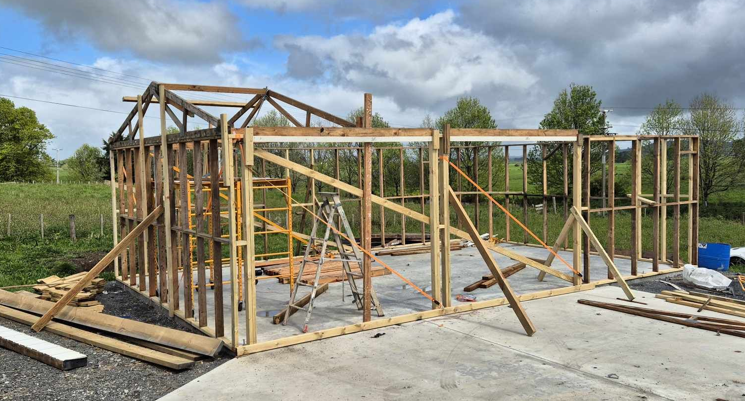
Yeah it's 6x9m and a 2.4m stud. At my last place I had a 12x9m with 3m stud, and at first I loved the idea of having a huge open big single space. But the problem is that if you want to do painting, or grinding or whatever... you have to cover up EVERYTHING. So usually I just went outside anyway haha. Then it all just ended up full of junk anyway. So this time, on a rural section so I can have multiple things. So smaller workshop area but then have a big storage container, will build a little hut for the ride on mower, and so on. Later on will hopefully have a little painting area or hot works area that you can just go get some work done without 100% admin time tacked on top. But priority is to get this up, and get carina running for starters! I've got a few issues at the moment though, all of the windows that were in it were a bit shit, and someone stood on the pile of glass and broke most of them. I've patched up where the old side access door was (as goes out to nowhere) So I'm a little short on cladding, and need some better windows. I drew a decent model of it for when I submitted my plans to the council for consent, it's been handy for checking dimensions of 2nd hand doors and windows to try come up with a plan for how they might fit. Probably need a bunch of smaller ones rather than gigantic things.
-
Not great at the moment. Have been away for a work a lot, and then have also started putting my garage up. So although that's setting me back a bit on having time/energy doing car stuff. I'm hoping that It'll let me catch up once I've got some extra covered space and so can start burning the midnight oil! Hopefully get a few more trusses up today if it keeps clearing up.
-
I cant tell from your pics, but the most likely source of fuel problems will be conductive heat (metal fuel rail bolted directly to engine, transferring heat into fuel) If there's a way to mount some plastic washers to isolate your fuel rails from touching the motor. This will likely make the biggest difference if fuel temp is your issue. Is this car running a fuel surge tank? Generally EFI systems are less susceptible to fuel boiling as the pressure is so much higher.
-
@Truenotch it sounds like you're going to be making some sort of cardboard based erotica? ...Subscribed
-
Thanks for posting, god these type of multi day drag and drive events. Just so friggen cool. I absolutely love that you're carrying your house around on the drag car hahaha. The bit about taking the other guys driveshaft cracked me up, I can just imagine it "Hey mate since you're totally fucked anyway..."
-
Noodly Aspirated
-
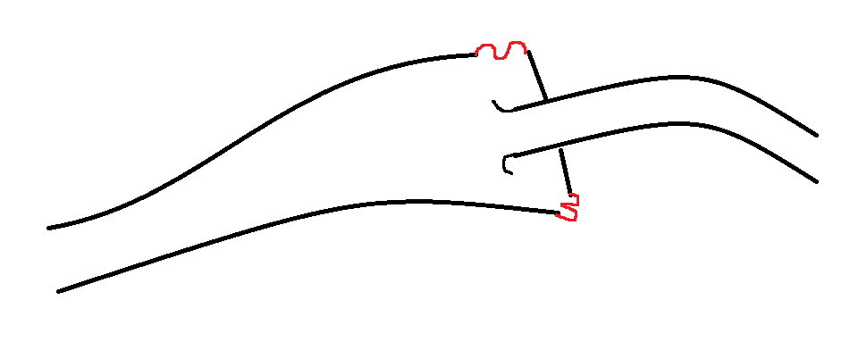
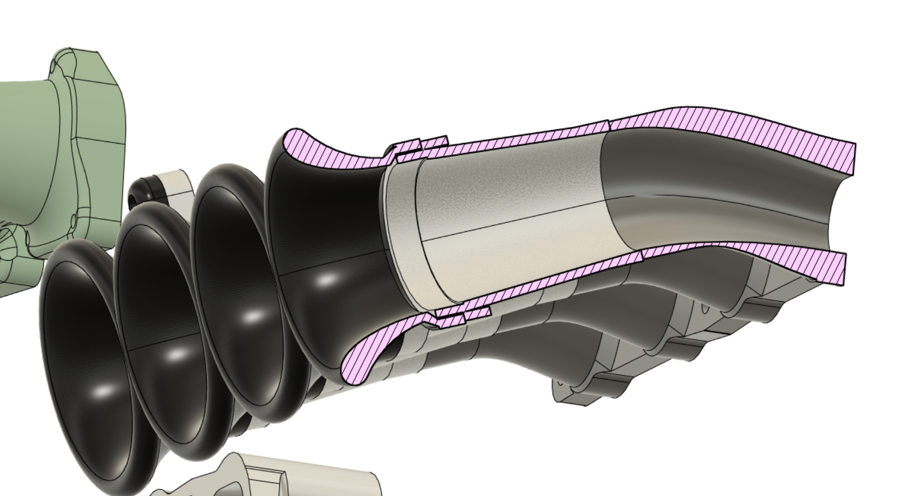
I would probably look at hard mounting the airbox to the chassis, and then having backing plate part that fixes to the engine. With some sort of rubber interface that allows movement between the two. As if you have the whole airbox off the motor like a big lever arm, 1 degree of movement ends up a lot of mm of vertical travel at the very end. Something like this maybe EDIT: probably one of the most important overall things, is having as much clear area as possible around the perimeter of the trumpet, including the top face to the bonnet.
-
When I look at this I'm just 100% thinking a curved manifold is going to make your life a hell of a lot easier and it's not going to impact power at all. Looks like you either need to cut the bonnet (yuck) or bend the manifold or this is going to be near impossible unless you've got solid mounts. But having a gross shape at the end of the runners is way worse than having a manifold with a bend in it. One of my Echo manifolds had a bend in it like this and it didnt harm power what so ever, but meant I had more room for activities (running an extra fuel rail on top for nerdy purposes) Paraphrasing KPRs experiences a bit, but generally the important parts of a manifold seem to be right at the entrance, and what happens right at the port - and the motor is quite insensitive to what ever is in the middle. Like one of his manifolds had a massive step in the runners (in the wrong direction) and it made 0% difference to power, which is totally counterintuitive!
-
Sounds like it needs some time spent on accel enrichment. The flyby vid is sweet though! https://youtu.be/TIQC3xiJYNA?si=rBsWJdMHFJN4cxoc
-
+1 to elevation changes looking like heaps of fun. The elevation changes at Hampton are cool, but they're a bit more gradual Well done on pedalling to 1st and 2nd to the HPA lads! How good! I am super stoked to see the car back out there getting shit done.
-
Damn dude, you've knocked it out of the park with those covers! Looks incredible. Colour really suits it too. Is 5M_GX designation a throwback to an HKS variant of the motor or something? I absolutely cant wait to hear this thing sing! What's left to do now?
-
@dabuzz are you sure that everything on the car gets recerted? My understanding is that if you've got an existing cert, but then change just one thing, they effectively recert for just that. Any clarification on this one please @cletus
-
Looks friggen awesome.
-
Hah, cool! Developed in early 80s so almost period correct for some idiot to throw into a mid sized coupe https://en.wikipedia.org/wiki/Yamaha_OX66_engine Amazing power given the crappy injection and distributors etc. Amazing power for displacement.
-
Unless you had the filter plumbed up backwards, wouldnt it be doing nothing? As its just an anti drain back type thing?
-
Ages ago a mate bought a JZA70 Supra, it was a good price, the right model, etc etc etc.... And it had this absolutely massive air brushed Conan the Barbarian on the bonnet. It was incredible, and we mocked him mercilessly well past the point of repainting the bonnet. In hindsight, what a bunch of cultureless savages we were to not appreciate the art work. For shame! I absolutely cannot wait to see some air brushing on the panel van.
-
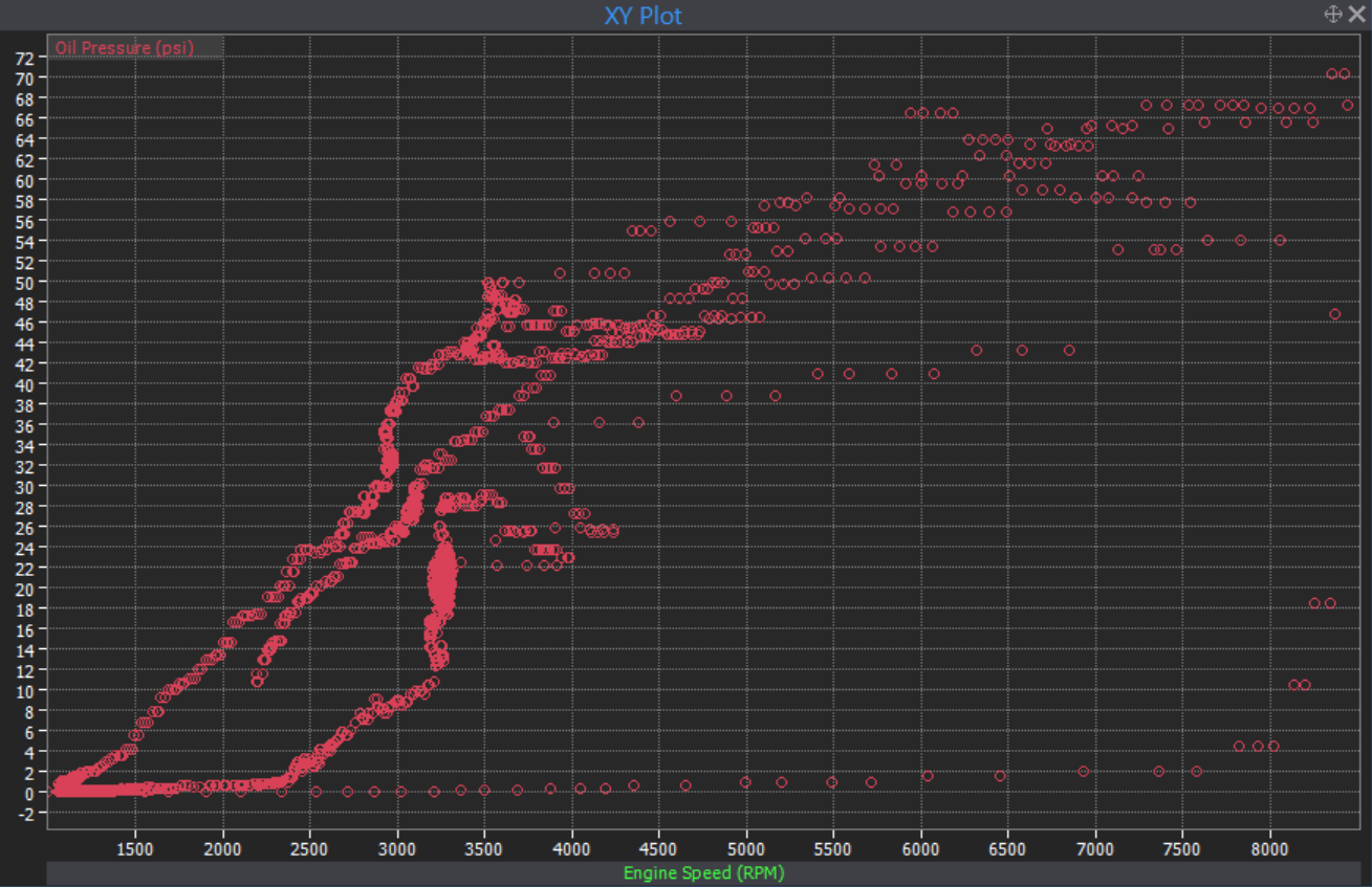
That's a weird one, if it's easy to get the oil pump off, perhaps could try shimming the spring on the relief valve and see if it makes a difference? This is the sort of oil pressure spread I get with V6 motor (just before it shit itself, one of the times it shit itself) Dont get 30psi until around 3000rpm, dont get to 60psi till 6000ish so I'm not sure if you'd see this problem (or not problem) become evident by running the motor and idling it.
-
Discuss here about Yoeddynz's little Imp project...
Roman replied to yoeddynz's topic in Project Discussion
This might sound crazy but there isnt something like a lego character stuck in there? -
Discuss here about Yoeddynz's little Imp project...
Roman replied to yoeddynz's topic in Project Discussion
Does a flat six actually have any reason to sound different than a straight six? As in, arent they both even firing order? Wonder if the "flat six sound" is more "air cooled sound"