IvyMike
-
Posts
235 -
Joined
-
Last visited
Recent Profile Visitors
910 profile views


IvyMike's Achievements
Advanced Member (3/5)
294
Reputation
-
Sodium Saccharin for the most part, at least in one form.
-
Wish I had seen this a week ago. Locked it in yet? EDIT: https://www.trademe.co.nz/a/marketplace/business-farming-industry/industrial/manufacturing-metalwork/welders/listing/3266379839?bof=QecdUlNO
-
What resin do you use for your castings and at what ratios? The quality looks great.
-
Just try this.. void activateCoilsIfLow(uint8_t inPin, uint8_t outPin) { volatile unsigned long timestamp = 0; if (analogRead(inPin) <= sensorThreshold){ coilState = HIGH; coilPin = HIGH; digitalWrite(outPin, HIGH); timestamp = micros(); while (coilState == HIGH && coilPin == HIGH && (timestamp + coilCharge) > micros()); //Busy wait digitalWrite(outPin, LOW); coilPin = LOW; timestamp = micros(); while (coilState == HIGH && coilPin == LOW && (timestamp + dwell) > micros()); coilState = LOW; coilPin = LOW; } } I'm not sure how long your trigger period is, whether an ignition cycle could repeat during one combustion cycle, or whether that would even matter.. but I assume this would do what you're intending your code to do.
-
Would it be on time? I think your misfiring is caused by the main execution loop having to cycle through all the other cylinders before coming back to the active coil and checking micros() as the while loops behave like if statements. Have you tested the frequency of the main execution loop? I know some of those Arduino library calls can be particularly slow which could be causing large lapses in time.
-
Maybe I'm missing something here but how does currentMicros get updated within the while loops? Edit: Nevermind, just realised that this operates across calls to activateCoilsIfLow. Is there any point in guarding the second two while loops with the state of the input sensor once you've put the coil state into high? Maybe the input sensor state is changing and preventing the later two loops from being executed.
-
Congrats. How did you sort the ignition drivers in the end?
-
 IvyMike changed their profile photo
 -
Could be a 555 flasher circuit or some other astable multivibrator. Pretty much what Yowzer described. Hard to know without seeing the layout.
-
Does the flash rate slow down? Total stab in the dark but I'd guess your multimeter probe is introducing some stray capacitance
-
It's going back a while but I think you only had to drill out the holes on the turbo exhaust housing to fit the old studs, grind away a bit of the exhaust housing so that the nuts could turn, and fit a new oil line. You will need a new down pipe as well I think.
-
Yeah, that's usually how it starts out until you get used to it. A tc05 exhaust housing will give you better response but at the expense of top end. I think the A/R is 0.49 for them. I had a TC06 on another engine with the standard exhaust housing (0.63 A/R IIRC), it wouldn't get on boost until 4000rpm. To be honest a lot of those older TC series turbos are pretty inefficient, even the td05-14B wasn't too good at higher levels of boost. I think either the small 16G or big 16G is the standard port of call, they give you a lot of leg room if you want to do something later.
-
I had a td05-14b on a rebuilt G63B years ago. Managed 200rwhp @ 13psi with a type A injection system and 8.5:1 compression. Definitely doable without too much tweaking, but that was on its outer limits though.
-
Good to hear. Might be better off flushing the buffer if that's the issue. The only reasons I can think of that would stop the coil from firing are, as you said, not enough volts or you placed some form of resistance after the IGBT. Typically the gate needs to be at least 4V higher than the emitter with an IGBT.
-
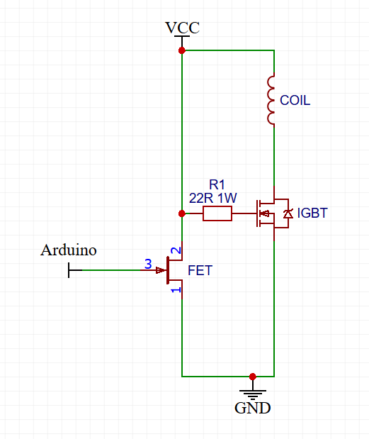
On your schematic it connects to the boost converter + via a 330 Ohm resistor, states grounds are separate. Is that what you meant? Grounds should never be coupled using resistors and all elements of a circuit should be tied to a common ground. Also, I'm a bit dubious about you tying the output of each FET/IGBT to ground behind a diode, I'd get rid of them. I'm pretty certain most ECUs run low side drivers i.e. place the IGBT after the coil so it grounds the coil. I think right now, without the use of a bootstrap circuit (something to ensure that Vg is always higher than Vs) you've got some funky stuff going on as the inductive kickback will overwhelm in the input signal. Somehow you've managed to get it to latch up each gate using those resistors but it definitely doesn't stand a chance doing what you want it to with the IGBTs signal input being tied to ground via diodes. Fuck it, this is roughly how it should look: This will invert the signal but you can just negate that in software (Coil fires from high to low). Might be worth protecting Vcc with a diode on the IGBT side. EDIT: Also, I forgot to add a resistor between the driver FET and Vcc. Right now it'll just short and explode.

-
Random guess: try prefixing " int thermoSensorNewVal, thermoSensorOldVal;" with "volatile". Also, does the arduino share a common ground with the 12V boost converter?