Adoom
-
Posts
2,279 -
Joined
-
Last visited
Content Type
Forums
Downloads
Events
Gallery
Everything posted by Adoom
-
Actually, this looks promising. https://www.aliexpress.com/item/1005002602810952.html?spm=a2g0o.productlist.0.0.257d6ddekfRGNd&algo_pvid=d840d349-13ad-42b0-a9bb-c5aa26c06c47&algo_exp_id=d840d349-13ad-42b0-a9bb-c5aa26c06c47-11
-
If anyone has links to part numbers for common OEM connector terminals, that would be super handy. I know you can get them from places like RS components, but it's often hard to identify them from the one image they show you.
-
Please tell me you have a plan to narrow the track so it's the same as the maxi. I think a stealth look would be cooler than MASSIVE arch extensions.
-
Mine is one of those WTF does this even fit super skinny allen keys ground to a long chisel tip. I found that it works better than wire because it's stiff and won't easily bend.
-
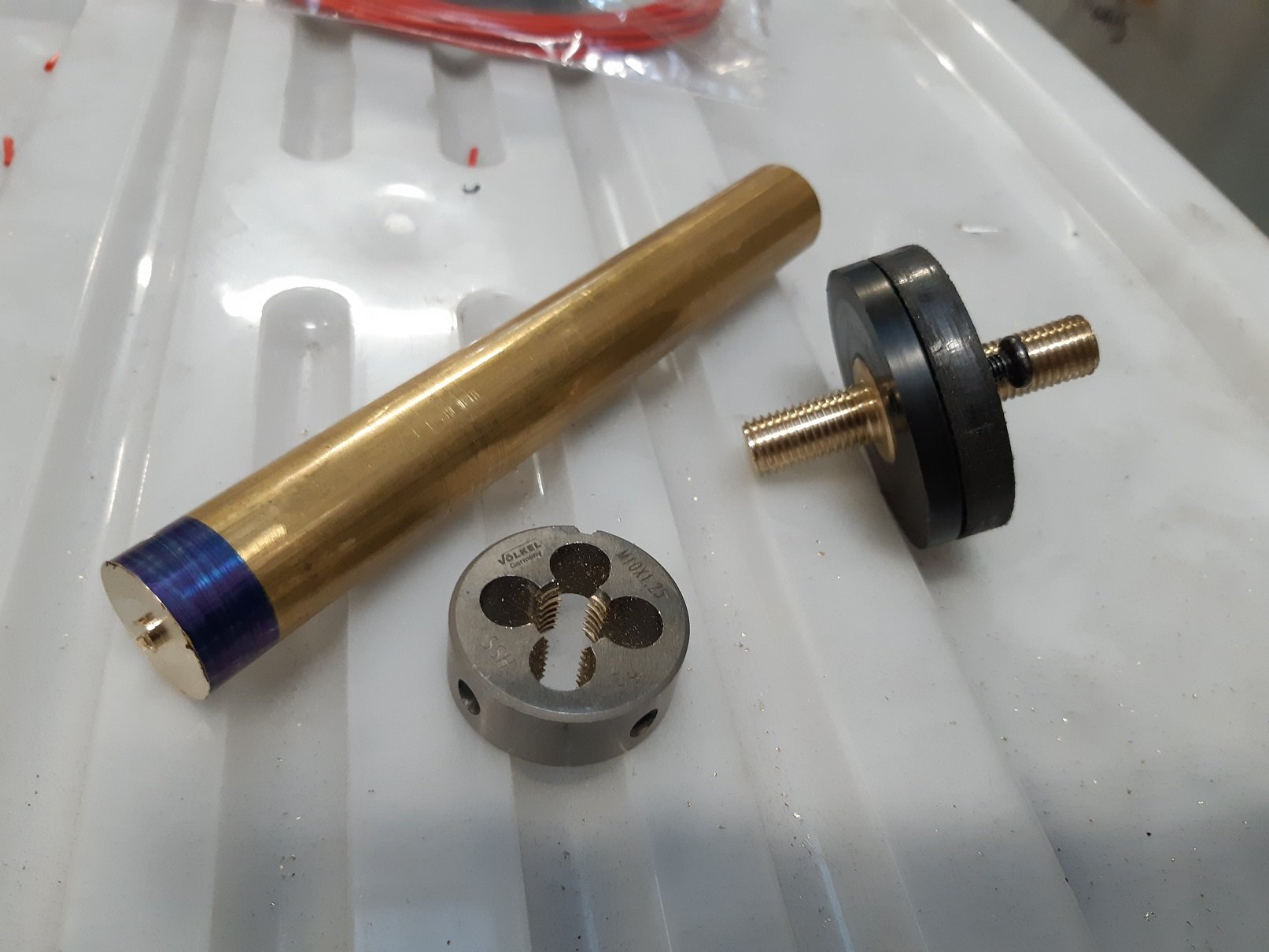
I've been doing the wiring. It's not an exciting thing to take photos of. I need to relocate the battery in the boot and I'll run the cable inside the car, so I decided I wanted a through-bulkhead stud thing so I had power right beside the fusebox/ecu and in the engine bay to connect the starter cable to. Googles through-bulkhead stud thing. $50!!! I'm sure I can make one for less than that. So I spent $26 on a short bit of 20mm brass bar. I tell myself I'll have lots left over for something else. I already had a big big of acetal I could use for the body. So I spent maybe an hour on the lathe making round things and round things with holes in. To cut the thread... I initially attempted it with my cheapo 'Frost' die, because brass is 'soft', right. And it was entirely useless, Massive amounts of effort required to cut a single thread. So I spent $24 on a volkel die.... plus $6 shipping. I've said it before... damn these are good. It's so fucking sharp, I could just about start the thread holding the die in my hand! It was too big for my die holder... so like a barbarian I used vice grips. Those small screws are countersunk so they don't end up being made live.

- 201 replies
-
- 13
-

-
Too late now, but I reckon citric acid would have worked on those steel wheels. Citric acid is cheap, you get it in powder form. I think I got my on trademe. A big bulk bag, not the teeny pots used for making food things. Or electrolysis would be safer, no chance of leaving it in too long. Also cheap. In both cases you need a plastic thing you can submerge a wheel in. Then you give them a rinse and wipe with a scourer pad. Nice clean metal, until it dries and immediately flash rusts.
-
Just for the on hold bit... Don't listen to that guy at work. You have to keep renewing the 'on hold'. If you don't, you will get a bill from NZTA for unpaid rego from the date the hold ended. This happened to me. AFAIK, to change the rego class, you just tick a different box on the rego form at your local rego form place vtnz whatever. I have not done this.
-
What's the deal with factory quad headlights in a car made in 1971. Can I have all four doing DIP and all four doing High beam? Or does it have to be only two on DIP and four on High beam?
-
I think I may be owed an icecream. A photo will be sufficient.
-
I have the same one as @cletus. I could definitely do with it being a little wider. It's not quite big enough to fit the engine crossmember in. I cut a hole between the gloves and siliconed in one of those cheap LED floodlights. Now I have issues with it creating shadows, so I want to put another one in the top. I made a cyclone dust collector out of a 20L bucket, some ~50mm plumbing pipes and my old vacuum that had lost all of its wheels. The bucket lid is thin so I screwed a bit of wood to it to have something to glue the pipes to. You put a straight pipe in the center of the lid, stick it into the bucket a bit, not flush with the lid. This goes to the vacuum. Right on the edge of the lid you put a 90 deg bend(inside the bucket), point this so the air and dust goes around and around the walls of the bucket. The other end of this goes to the cabinet. It seems to work well. I definitely must try what @~Slideways~ did with the pickup.
-
I have a 70 Watt one. Its original purpose was to power a computer fan to try ventilate a shipping container. Now it lives on the ride on mower. I used to leave it attached all the time, but it eventually boiled the battery... over several months. Now I just stick it on every now and then.
-
So I started looking at the Triumph wiring loom to work out how I will connect the Link ECU loom to it. Lucas, the prince of darkness apparently did not believe in fuses or relays. There are 3 fuses and a relay for the horn, that's all. I've found some dodgy repairs to the instrument wiring. And someone had put in a relay for the headlights, but it's really old and gigantic, I had assumed it was an external voltage regulator before investigating. A section of loom has also been lengthened, with different colour wires... I haven't worked out why. To sort out the dodgy repairs I've had to unwrap the whole loom to decipher the how and why, so since I've gone that far I may as well modernise it a bit and put in a new, larger fuse box and some relays to take the current load off the old switches. The OEM wiring for the Oil and Brake warning light is LOL. (The brake warning is if the front/rear circuit fails.)The lights are wired in series for power, but each has its own earth through their sensors. There is a description of how they work in the factory service manual... Ignition ON engine not running: Oil light "ON FAINTLY", Brake light "ON FAINTLY" (apparently so you can check the bulbs work) Engine running: Oil light "OFF", Brake light "OFF" (Yep) Engine running brake circuit failure: Oil light "OFF", Brake light "ON BRIGHT" (Cool, makes sense) Engine running low oil pressure: Oil light "ON FAINTLY", Brake light "ON FAINTLY" (Ummmm. What!? I know they are "faint" because they are in series, but surely there was a better way to do this.) It does literally say "FAINTLY", which in real life is probably so dim you can't tell it's on, because Lucas. However, I've got a oil pressure sender for the ECU, so the oil warning light will be controlled by the ECU. I am undecided if I will retain the brake warning light, as far as I can tell many models didn't have it. I also had trouble finding a wiring diagram that included the light and sensor. Some diagrams listed the light and sensor as items 51 and 52 but they were missing from the actual circuit diagram?! I eventually found it in the factory service manual under "Left hand drive models only"...??? If I decide to keep it I have loads of spare inputs/outputs on the ECU, so I could connect the sensor to the ECU and get it to control the light as well.
-
I'm going to rewire the headlights on the Triumph because NO FUSE and NO RELAY, all the current goes through a 50 year old switch made by Lucas, the Prince of Darkness... With headlight wiring.... when you use high beam, should the dip and high filaments both be on, or only the high beam filament?
-
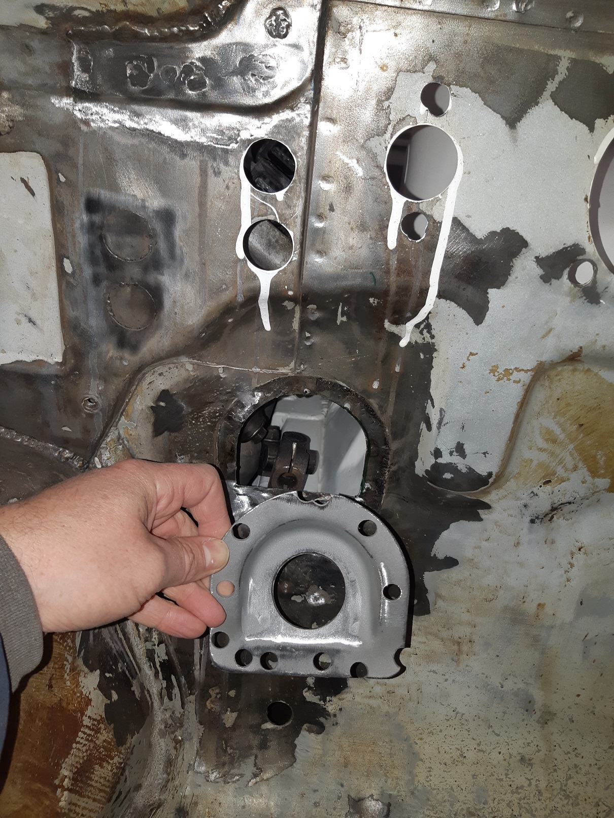
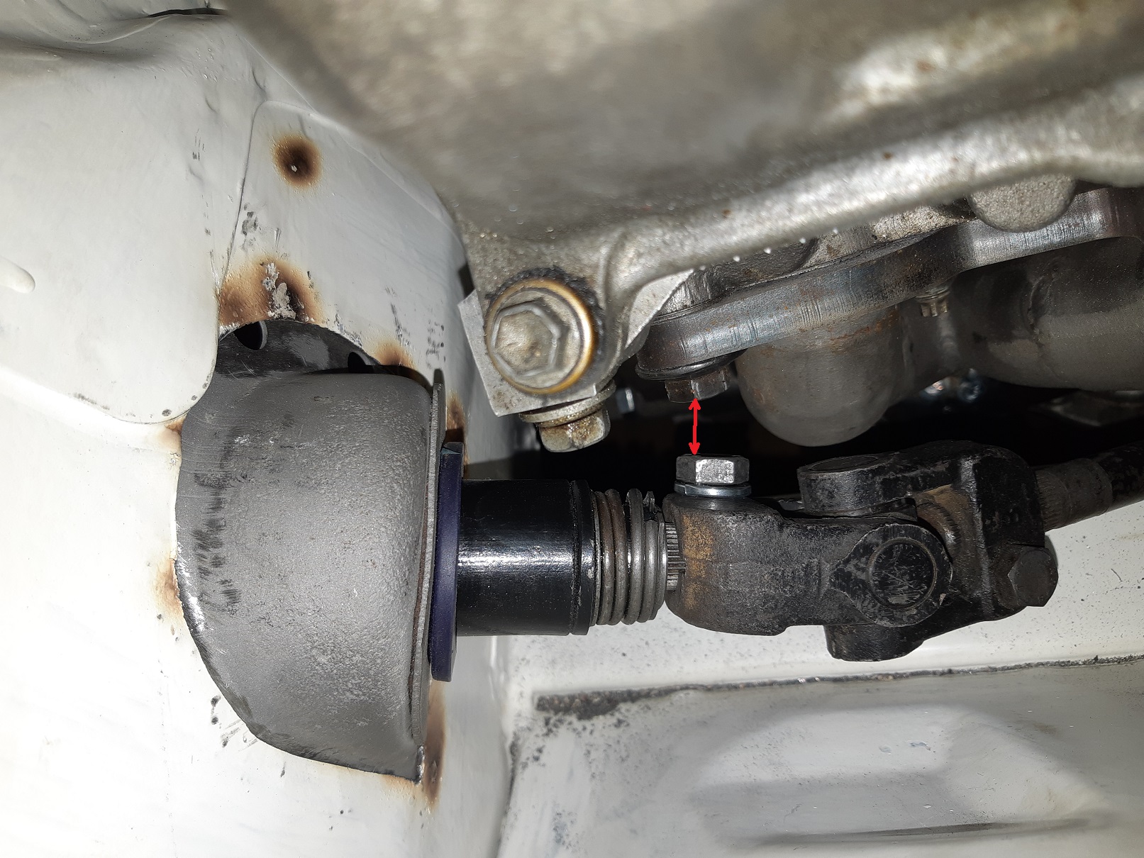
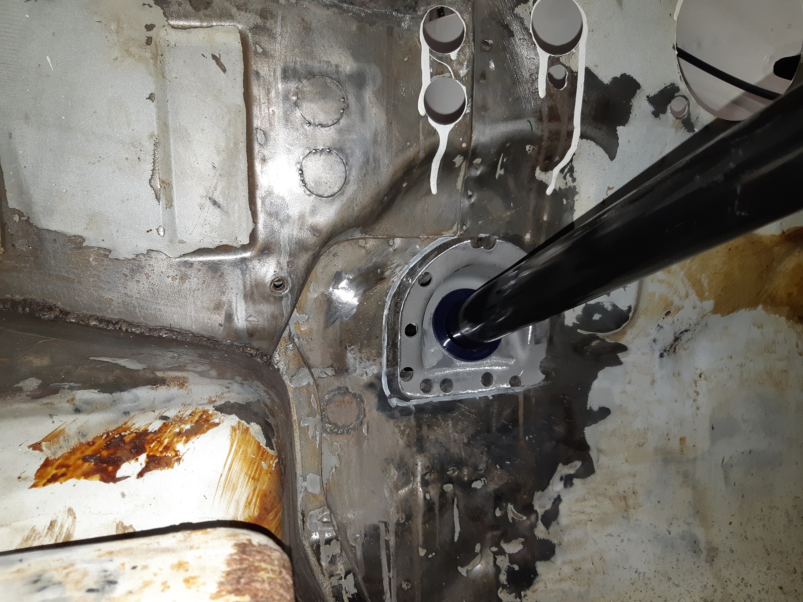
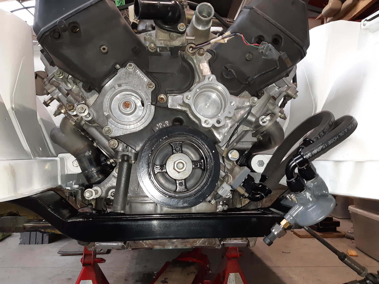
So I've been fighting for clearance for the steering off the rear stud for the exhaust manifold. I first tried replacing the stud with a bolt so it was lower profile. I still had negative clearance. The universal joint has a bolt that goes right through with a nylock nut which sticks out a fair bit. I looked at my starlet, and there is no nut, one side of the hole is threaded so you just use a bolt. I decided to replicate this method. I drilled and tapped it to the next size up UNF thread(I didn't want to mix and metric and imperial in the same assembly). But now the U-groove in the end of the steering column was slightly too small for the bolt to slide through. So stripped down the column and put it in the lathe. Fuck all needed to come off, it's now just the right size to thread the bolt in by hand. I painted it and regreased the bearings too. That got me down to zero clearance... you can turn the wheel, but the corners of the bolt heads just clip. Time to get drastic...er. Move the lower mount of the steering column over. To avoid making a mess of the panel behind, I used the flap disk until it was wafer thin then peeled it off. This intact lower mount is from the rusty car. I also kept part of the panel from the other car to use as a cutting template, and later I'll make a filler piece from it. It only needed to move a little bit, less than 10mm. Using a set of drill bits to measure the gap, the closest it gets is 9.5mm. The intermediate shaft now touches the chassis rail. When the engine is out again I'll make some room there.
-
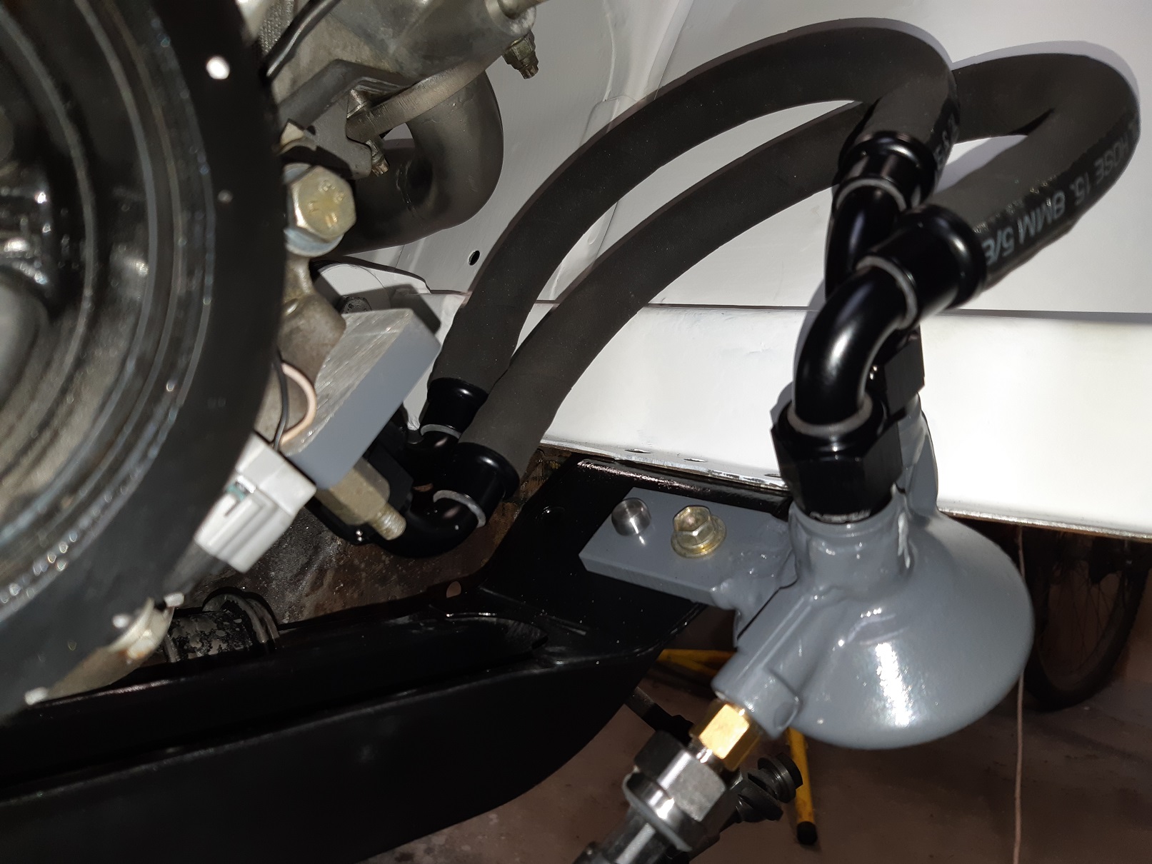
Sorted out the filter mounting. I later realised that the hoses were the wrong way around(when I sprayed myself with oil removing the filter to check if it was circulating). I'm going to mark it with bright paint so I don't make the same mistake again. I had initially intended to point the fittings at each other, so the hoses could be really short, but that didn't work out. When I weld the front panels back on the car, the filter is shielded by those.
- 201 replies
-
- 13
-
-
@johnny.race Something to catch out new players on a tig. The ground lead goes to the POSITIVE connection, not negative! Don't have the gas flow too high, the guide that came with mine suggested 8 Litres/minute. I went through gas RIDICULOUSLY FAST. I turned mine down to 4 and it still welds fine.
-
These https://www.bunnings.co.nz/kincrome-400a-3m-jumper-leads_p0292103 I dunno if I got the 400 or 800Amp
-
Not bolted on clamps... But I got some kincrome ones from Bunnings. Surprisingly inexpensive. Even has an inline voltage thingo. The clamps are much sturdier than the flimsy SuperShit ones that are really easy to bend, they are plastic coated steel with 2-2.5mm thick copper teeth. The wire core is also a decent size. The cheap ones tend to make their wire look more heavy duty by making the insulation thicker but the core is still small.
-
Positive terminal on the starter motor touching the block...or maybe got a spanner or something on it?
-
I got some nice leather seats from an Alfa 156 for my triumph. But they have airbags. What do I need to do? EDIT: I've since worked out how the upholstery is removed and managed to wangjangle the airbag unit out of one of them. Guess I just need to snip off the "Airbag" tag thingy?
-
I would have made an attempt to bash the original valance into shape with a cheap set of hammers and dollies. Or even cut out the REALLY mangled bits and make little patch panels. Remaking the valance from scratch with all those curves in it is some advanced level shit. This guy who talks funny has good videos on making up patch panels. You should watch every single one of his videos. https://www.youtube.com/channel/UC6JPmJ_aicru8XPWr3EvJnw
-
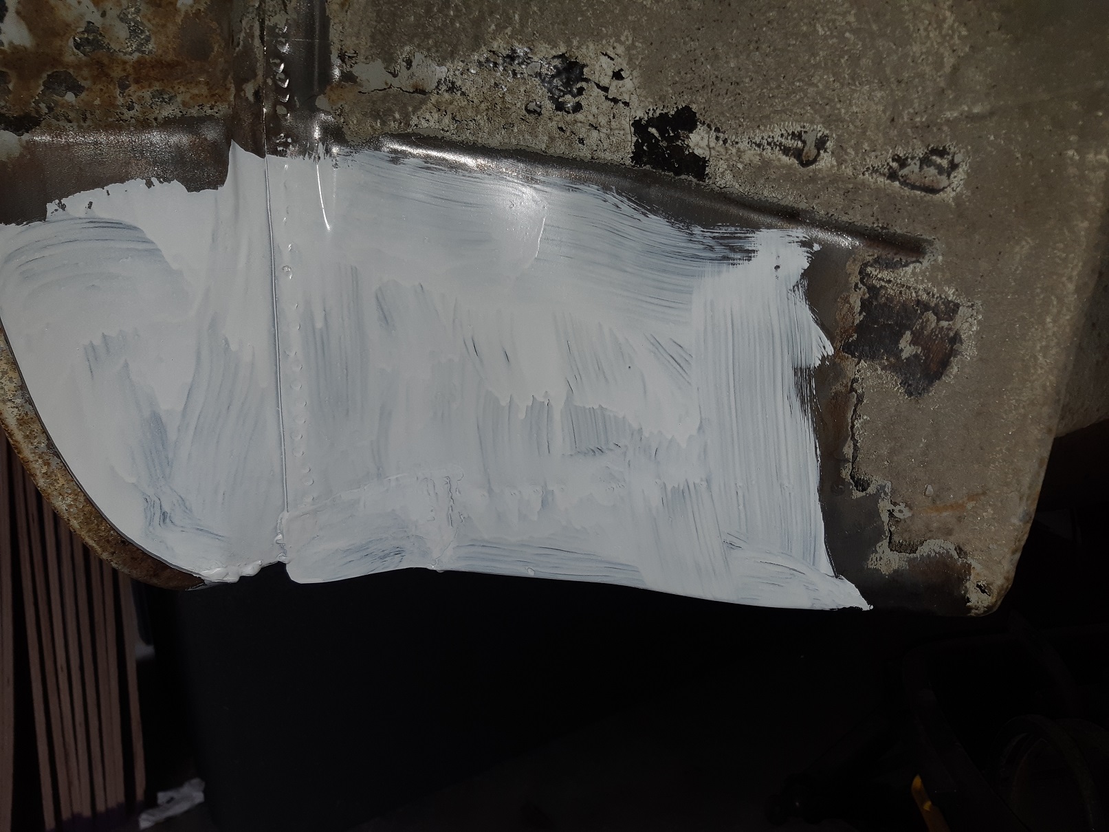
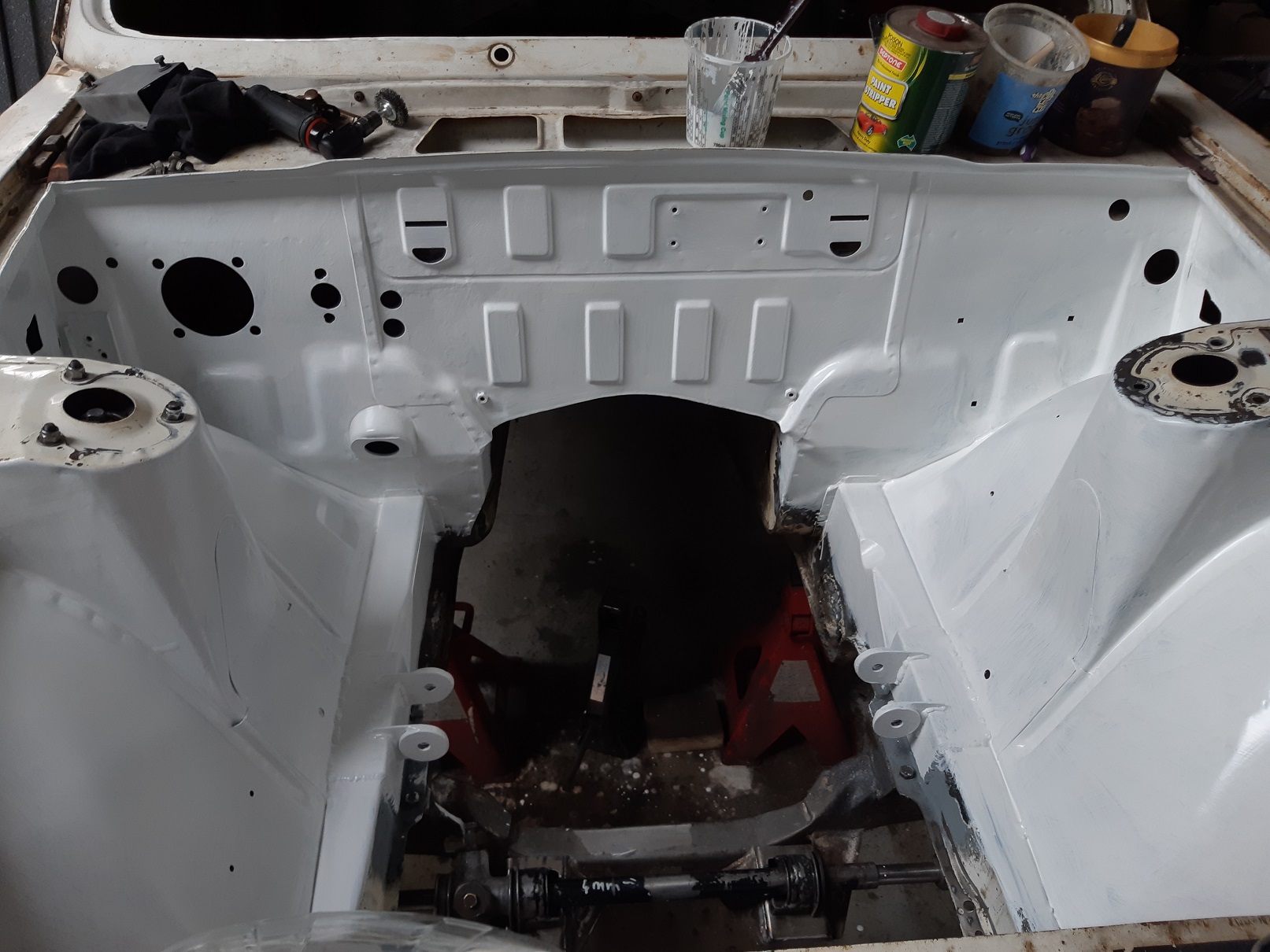
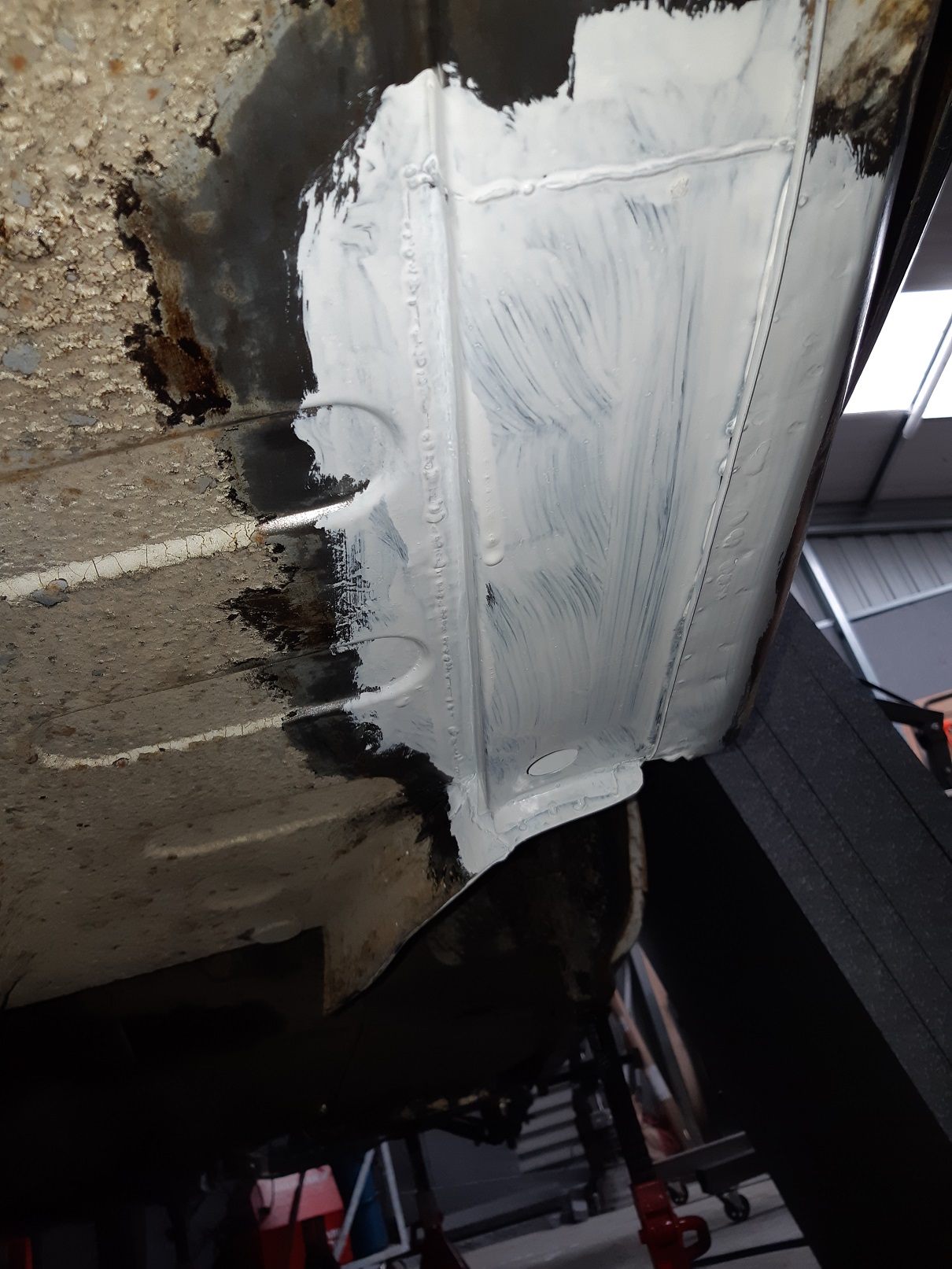
I had some areas of bare metal where I had made repairs or modifications. They kept getting minor surface rust, so I thought I should really get around to painting them with epoxy. The prep around the firewall was awful. All the seam sealer was bituminous tar stuff. So there was many hours of heat gun and scraping and rags soaked in kerosene and manual wire brushes to remove it. Then I needed to remove the paint because there were areas with surface rust and others where rust was creeping under the paint. So that was more many hours of knotted wire brush on the grinder. And the 3M abrasive pad thing on the grinder. And chemical paint stripper on the larger flattish areas and more scraping. Then there are lots of narrow spaces and gaps and corners I can't get into with the grinder. I found some reasonably priced little wire brushes at mytools.co.nz that were rated to use in a die grinder at 20000rpm without exploding. I also used small abrasive pads in the die grinder. Then I dusted it off with the air gun and wiped it all down with a cloth soaked in prepsol. And dried it off with the heat gun. And brush painted it with protec 408 epoxy primer. The engine bay has had two coats, the repair in the boot has only had one. I have some modern seam sealer to use. Hopefully it hasn't all gone hard... I think I might have bought it a couple of years ago.
-
No thinner because I was intending to brush this bit. I also don't have a gun that I trust not to be total shit. I would hope it's not lost its mojo, I only just bought it from panelstore.co.nz about 3 months ago.
-
It eventually did go hard after about 4 days. Even the leftover in the pot has turned into a solid block. It hasn't been particularly cold. I don't think it dropped below 9 in the shed over night. It's 25 in there now. I didn't wait after mixing. I'll try that next time. It still needs at least one more coat.
-
Got some Epotec 408 primer. Mixed it real good with a wooden stirring wand because it had separated. Didn't stir the hardener. Used the cup and mixed it 4:1 like the sheet said. Stirred it good in the mixing cup. Brushed it on. Just one coat, not real thick. Definitely needs another coat for full coverage. It still doesn't feel hard dry. I made too much so there was about 15mm left in the cup and that has gone real thick and goopy. Sheet says 16 hours to hard dry. But it's been at least 48. Did I do it wrong?