ajg193
-
Posts
7,796 -
Joined
-
Last visited
-
Days Won
1
Content Type
Forums
Downloads
Events
Gallery
Everything posted by ajg193
-
You can borrow my 5A ctek charger and use it on rejuvenate mode. It hasn't failed to save a battery yet
-
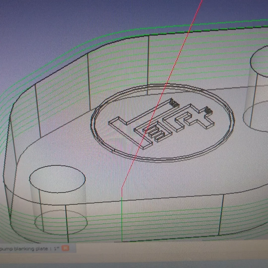
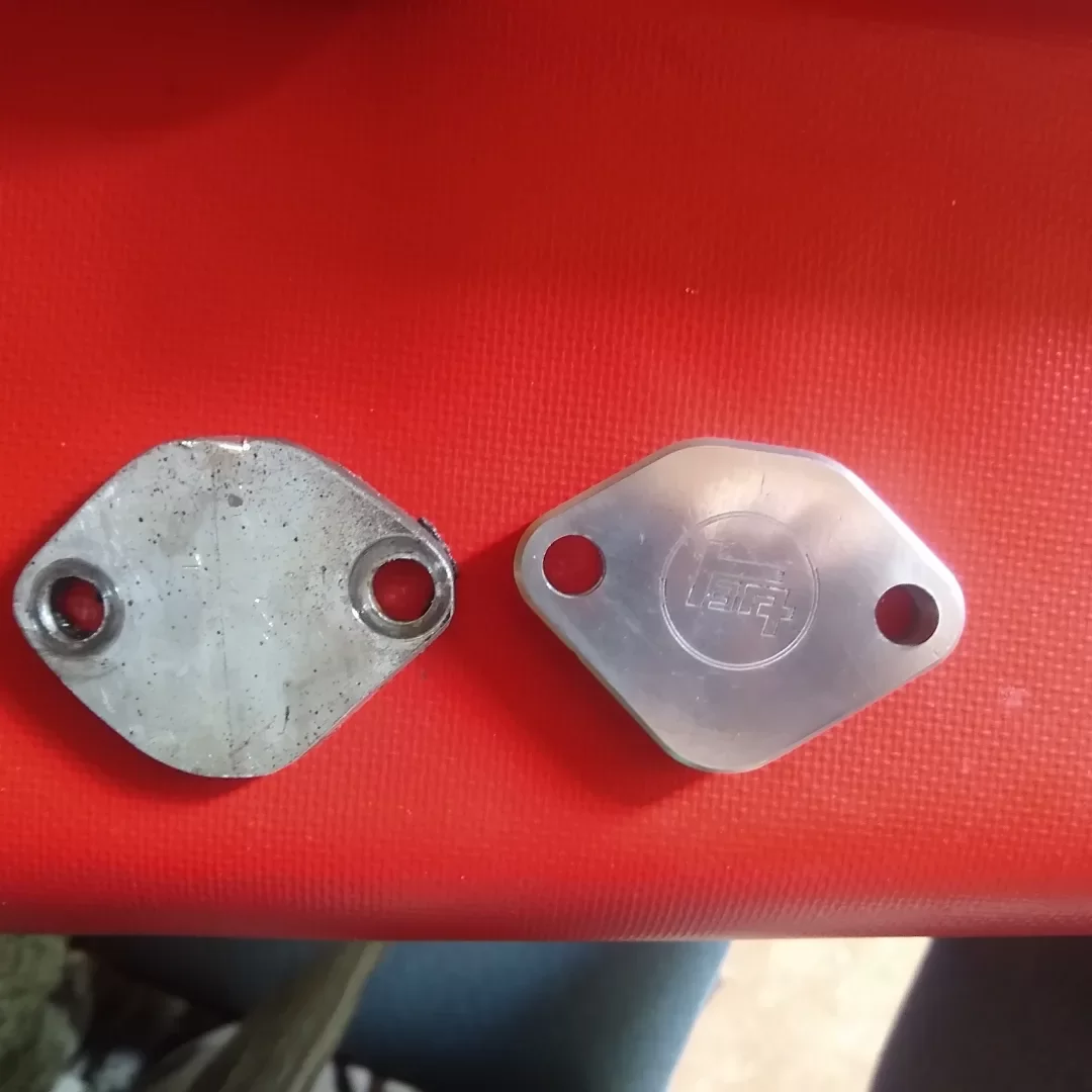
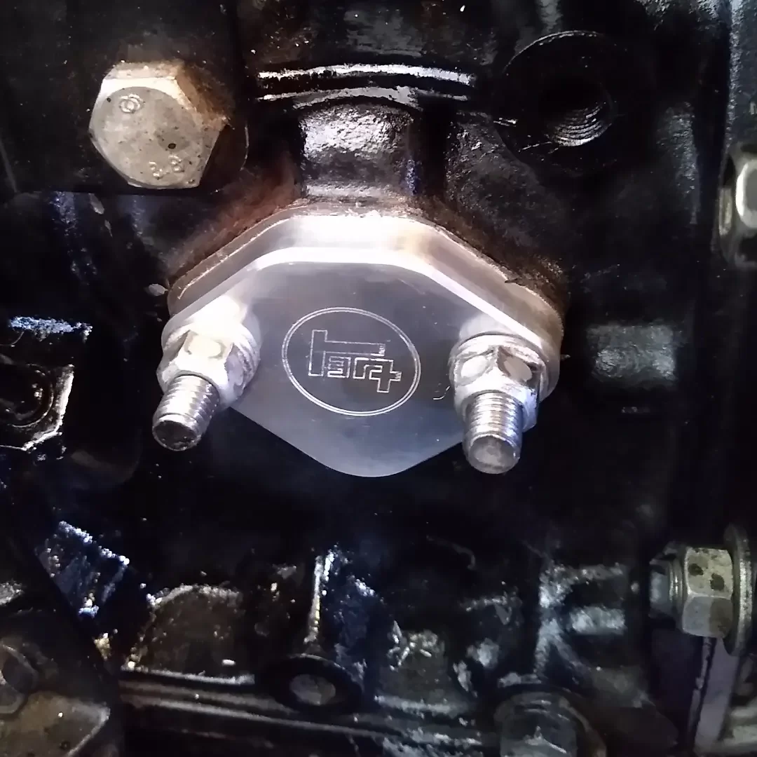
Not a particularly interesting update I had a bit of time to kill today so I figured I'd get around to making a nicer fuel pump blanking plate for the engine. I took measurements of the spacer from the original pump and made a model in FreeCAD and set the milling machine to work I'm not entirely sold on the logo, maybe I'll sand it off and put a smaller one on it in the future. Either way the plate is an improvement. I also cleaned the seatbelt yesterday as it was starting to get a bit gummy and wouldn't retract properly. I couldn't really believe the amount of gunk that came out of it.

- 90 replies
-
- 23
-

-
I wasn't aware that cruise economy was quite so insanely sensitive to ignition timing. Perhaps I will have to fine tune my cruise timing a bit more one day when I can afford getting up to cruise speed
-
Nissan Micra k11 - Mandy goes to a new happy home.
ajg193 replied to yoeddynz's topic in Other Projects
I'm failing to decode what those Facebook guys are saying -
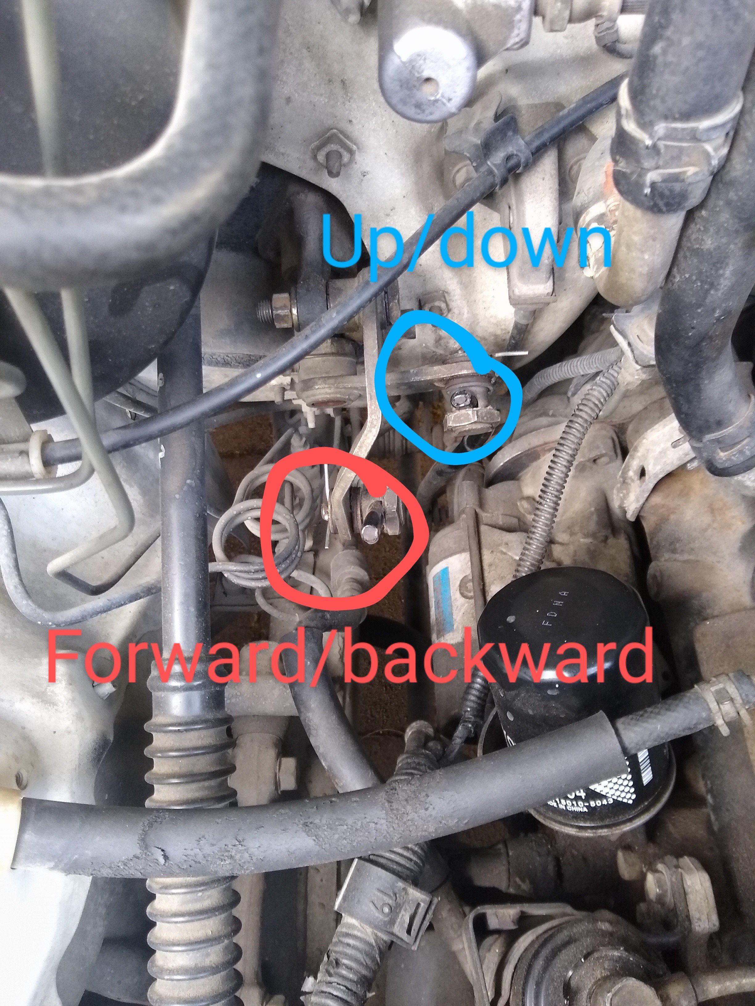
Here are the adjustments I made on hilux column shifter to get reverse back. Dunno how different it is on your van though. I think I pulled the forward/backward rod up quite a bit to move all the gears closer to the steering wheel.
-
My friend's blacktop auto does about 6.8 L/100 km if treated somewhat normally. Yours must have been proper chooched
-
What style are they? If they have the metal body with plastic ends you really don't want to screw with them at all or they will eventually start leaking out of the housing. If they are fully plastic then you should be good to do whatever.
-
I wasn't paying attention. What have you done to make the ignition system work on this?
-
Replaced like for like?
-
Is the starter motor ever fused on any vehicle? I thought they are always pretty much just a big honking cable capable of delivering many hundreds of amps at a direct short. Should always run the alternator sense wire directly to battery by itself, you can put a small fuse (like 1 amp) for this wire. There will be effectively zero current through this wire and it is essential there is no load on this wire or your output voltages will be wrong. The output of the alternator can just feed into the general 12 Volt network wherever you want, but you will still want a fuse on that.
-
Definitely needs cert if you do it after March 1999.
-
Fest is cancelled, just making sure you guys are all aware
-
May feel like a goat track to you plebs without springs, but in my car with lush springs it feels like.... a goat track
-
I've found my plate type LSD sucks a fair bit of speed off of the car if I am costing around fast corners. But in saying that, the LSD just makes your right foot way heavier and that's the main thing that determines fuel consumption in a car.
-
Changes coming in April, cars older than 40 not affected. Cars that have already been registered in NZ not affected. Factory or higher ride height now mandatory for cert.
-
You're wasting your time, Toyota already did all the measurements on these 40 years ago
-
^Whoops, I accidentally deleted your pictures when I changed my post contents to NAN, I think oldschool was still in brick mode at the time. (They disappear after doing a ctrl+r reload to clear your cache)
-
Biggest issue with curing large sections is excess heat generation in the thick areas causing internal delamination/blistering. As Nick says, heat it up nice and slow. Particulate fillers (like talc or calcium carbonate) result in less shrinkage, but can make it more brittle. Fibre fillers could be a good addition with this stuff though as it is pretty brittle (0.65% elongation at failure), and has a stupidly low tensile strength (only 30 MPa, generally epoxies are over 100 MPa). You shouldn't really have any problems with drilling and tapping epoxy but it would be best to use inserts so the fasteners don't clamp onto a constantly relaxing surface.
-
How does this filament hold up compared to carbon fibre filled nylon? A guy on youtube made some manifolds for his mini from that stuff and he claims it has held up well. He does use o-rings to seal around the ports though
-
Hyperblade's KP61 Racecar "KP61R" Discussion
ajg193 replied to Hyperblade's topic in Project Discussion
If you need any stuff turned up on a lathe or mill just hit me up and I'll sort you out super quickly -
Old engines are rumoured to handle boost better, something about the wear giving extra ring gap and bearing clearance for crank flex
-
KSR's KP60 Documentation discussion thread
ajg193 replied to kseries.rookie's topic in Project Discussion
Tang, desprang -
How is it on fuel these days?
-
Hesitation could be bad vacuum advance