Hyperblade
-
Posts
341 -
Joined
-
Last visited
1 Follower
Recent Profile Visitors
2006 profile views

.thumb.jpg.570970b401ac8d26ce9af7c1bf2bd8cd.jpg)

Hyperblade's Achievements
Advanced Member (3/5)
1.1k
Reputation
-
Especially when you add up all the time spent designing some of this stuff, then tweaking to actually be manufacturable. You end up skipping a lot of steps and saving time. We live in amazing times. It certainly makes me think twice about 3d printing my intake manifold in nylon, when i can just do it straight to aluminum.
-
Long shot i know, but does anyone in Chch have a decent 3d scanner they would be willing to lend me (I have a decent PC). I want to scan the inside of a wheel, caliper brackets, rear axles flanges. as I want to remake the caliper mounts, and i'm thinking it would make life easier to see where it is in 3d space. Happy to pay some money your way for the hassle.
-
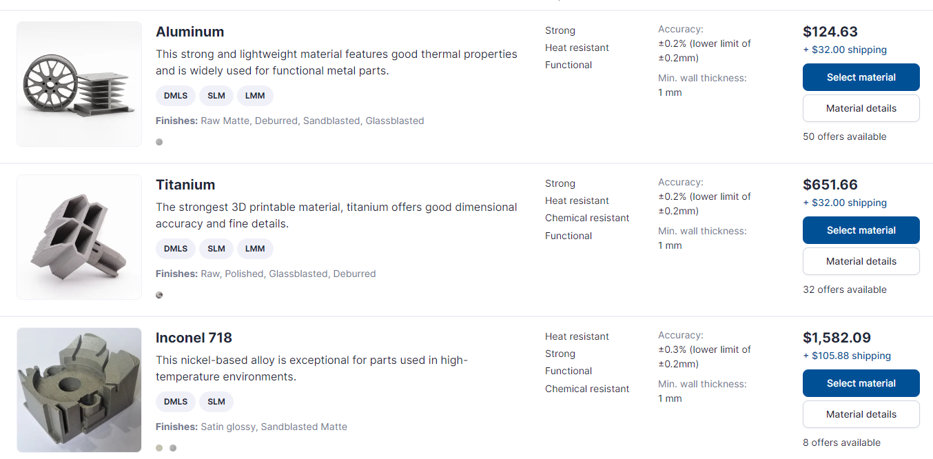
What a tease, i'm reading "3d printed inconel" and think this is really starting to get interesting, then you understandably cheap out by talking about stainless, lol. I'm surprised at the prices they are quoting, I thought it was just wishful thinking on my part, but 3d printing metal has to be seriously considered as an option when making a complex part now (assuming they produce a quality piece).
-
Advice required: Making complicated brake duct out of aluminium sheet
Hyperblade replied to Hyperblade's topic in Tech Talk
Those are interesting in their design, generally my understanding is you don't want to cover the rotor face as it can mean uneven cooling of each side so can promote warping. Although AP racing say you want 10% of air up each face and 80% through fins, but that's pretty hard for your average punter to design for. I'm hoping I can skip the foam part and just use pla, that's cheap and easy to produce at home, so if it works is a good solution for other similar parts. -
Advice required: Making complicated brake duct out of aluminium sheet
Hyperblade replied to Hyperblade's topic in Tech Talk
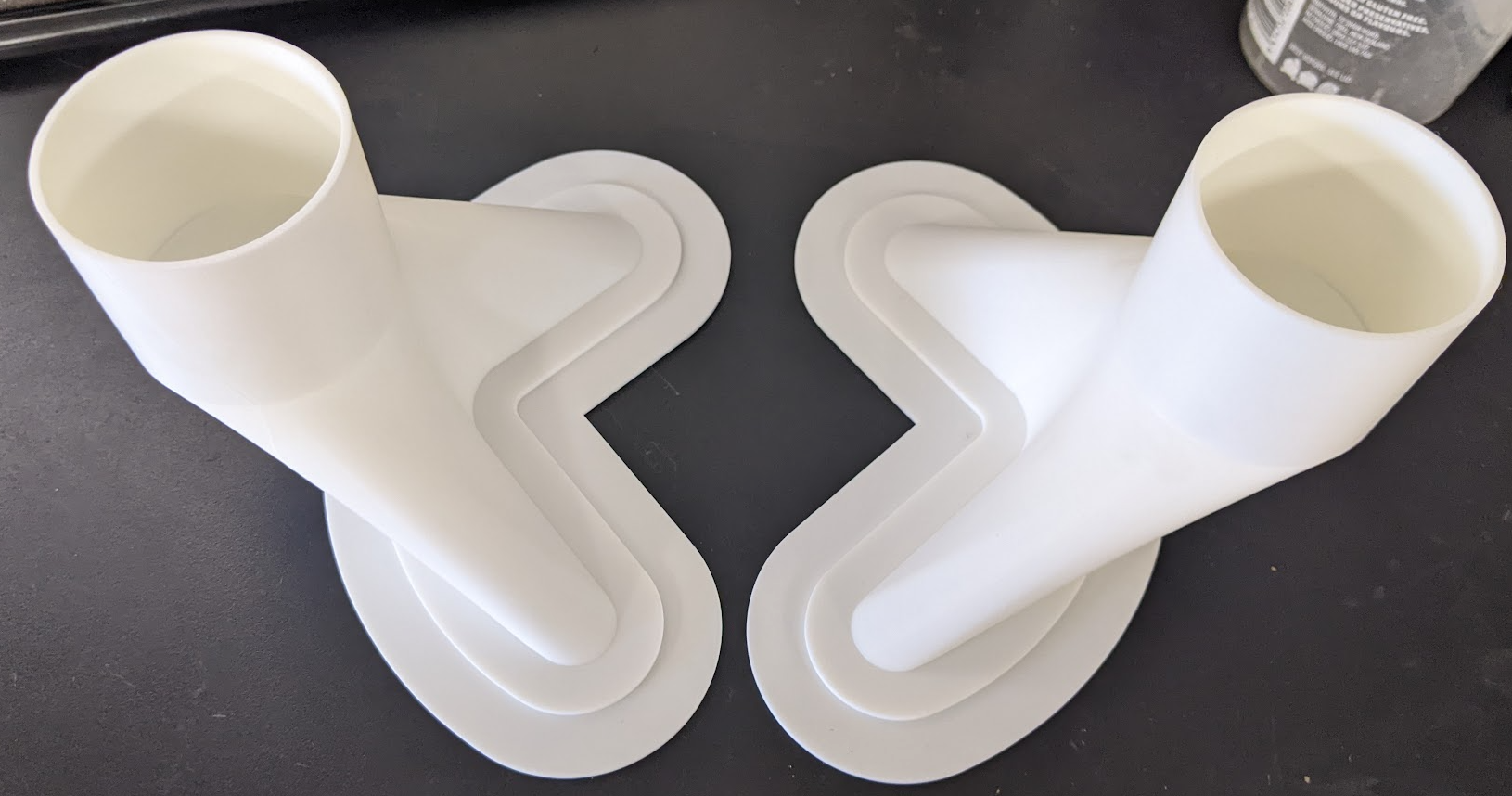
So after some reflection on this, I decided to make my life easier by going for 2.5", while I could have fitted 3" in, it just wasn't worth the effort at the moment. This allowed me to thicken up the outer edge of the plate, and move the air more inwards which is better. So plate ends up as this. For the ducts themselves, trying to get aluminium around them was proving too difficult for my skills, there was a couple of compound curves making life really difficult, even when I altered the ducting to be as simple as possible. I looked at casting but they would have been minimum thickness of 4mm and $1000 odd. I got a quote for 3d printing them in metal from https://craftcloud3d.com/ (min thickness 1mm) Actually not to badly priced $262nzd delivered for the 2 of them (in ali). But the current plan is to take these moulds in PLA and just wrap them in fibreglass, then melt the moulds out (found a friend willing to try it).
-
Race motor (cnc head, cams, pistons) on npd100 300hp odd (think that was at wheels too) designed for endurance racing, few $$$ involved but not crazy money.
-
Advice required: Making complicated brake duct out of aluminium sheet
Hyperblade replied to Hyperblade's topic in Tech Talk
Good idea, I have seen something similar done with 3d printed molds. This is actually a thing, pads create a hot spot, or so I've been told. Have been moving it after racing, but believe warping occured during race. -
Advice required: Making complicated brake duct out of aluminium sheet
Hyperblade replied to Hyperblade's topic in Tech Talk
Yeah was figuring all of that would be the case and was wishfully thinking it might have got easier, nothing is ever cheap being 1 off. Sounds like I'm going the aluminium route, i've take the time pressure off myself as i want this done right, so I can spend some time mucking around and see how far i get. Yep still WFH most days, thanks for the offer, but i'm probably ok to proceed at this point (but if you ever want to pop round and check it out just sing out), if not will give you a yell Thanks everyone for the thoughts/advice appreciate it! -
Advice required: Making complicated brake duct out of aluminium sheet
Hyperblade replied to Hyperblade's topic in Tech Talk
I run the ex TRS Michelin slicks which are 13" and have amazing performance and cost me bugger all (new are $450 a tyre). I have a fairly large stock pile of them and the car looks and handles better on them. Yes, my life would be a whole lot easier if i ran 15" but it's worth the pain for the performance. -
Advice required: Making complicated brake duct out of aluminium sheet
Hyperblade replied to Hyperblade's topic in Tech Talk
Do you think it would be possible to do the duct and the plate as one piece in carbon/fibreglass? Does it have to be machined afterwards to give the tolerances required? Can you use PLA as the one time mold or does the resin eat it? Anyone you recommend in Chch for the carbon/fibreglass work? Correct, was planning to do this myself (i have limited experience), but running out of time before race day and current thinking is to take a step back do a proper job on this. -
Advice required: Making complicated brake duct out of aluminium sheet
Hyperblade replied to Hyperblade's topic in Tech Talk
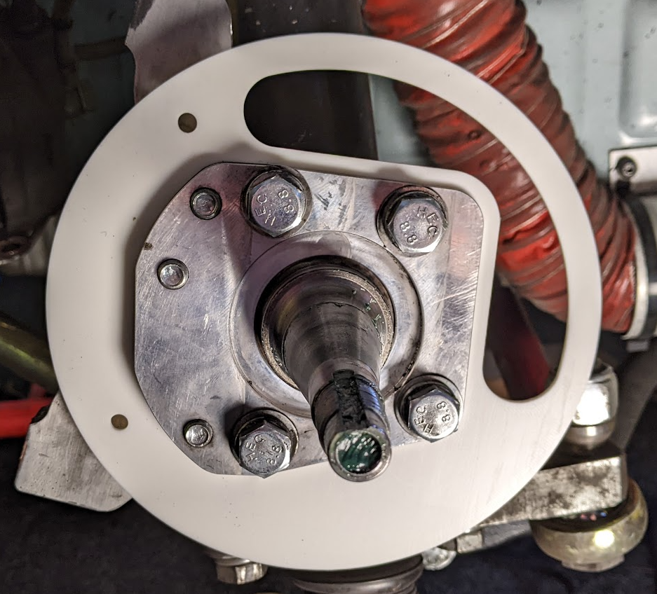
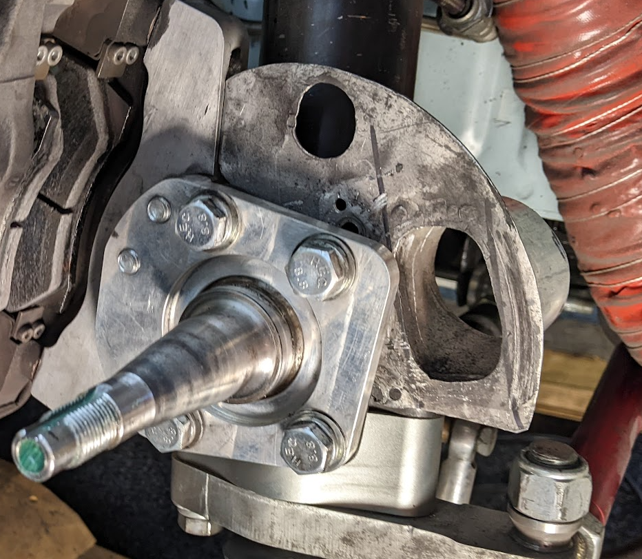
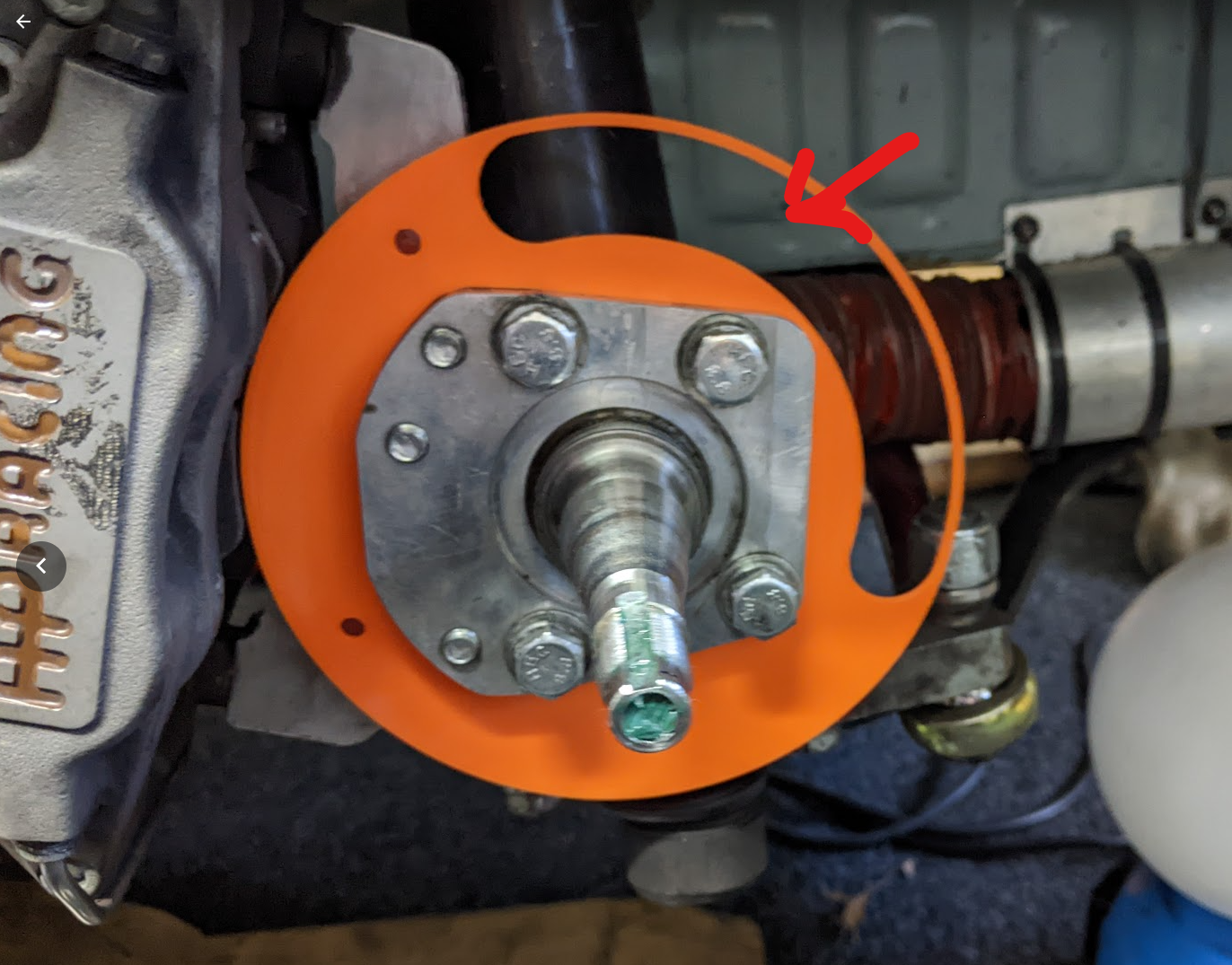
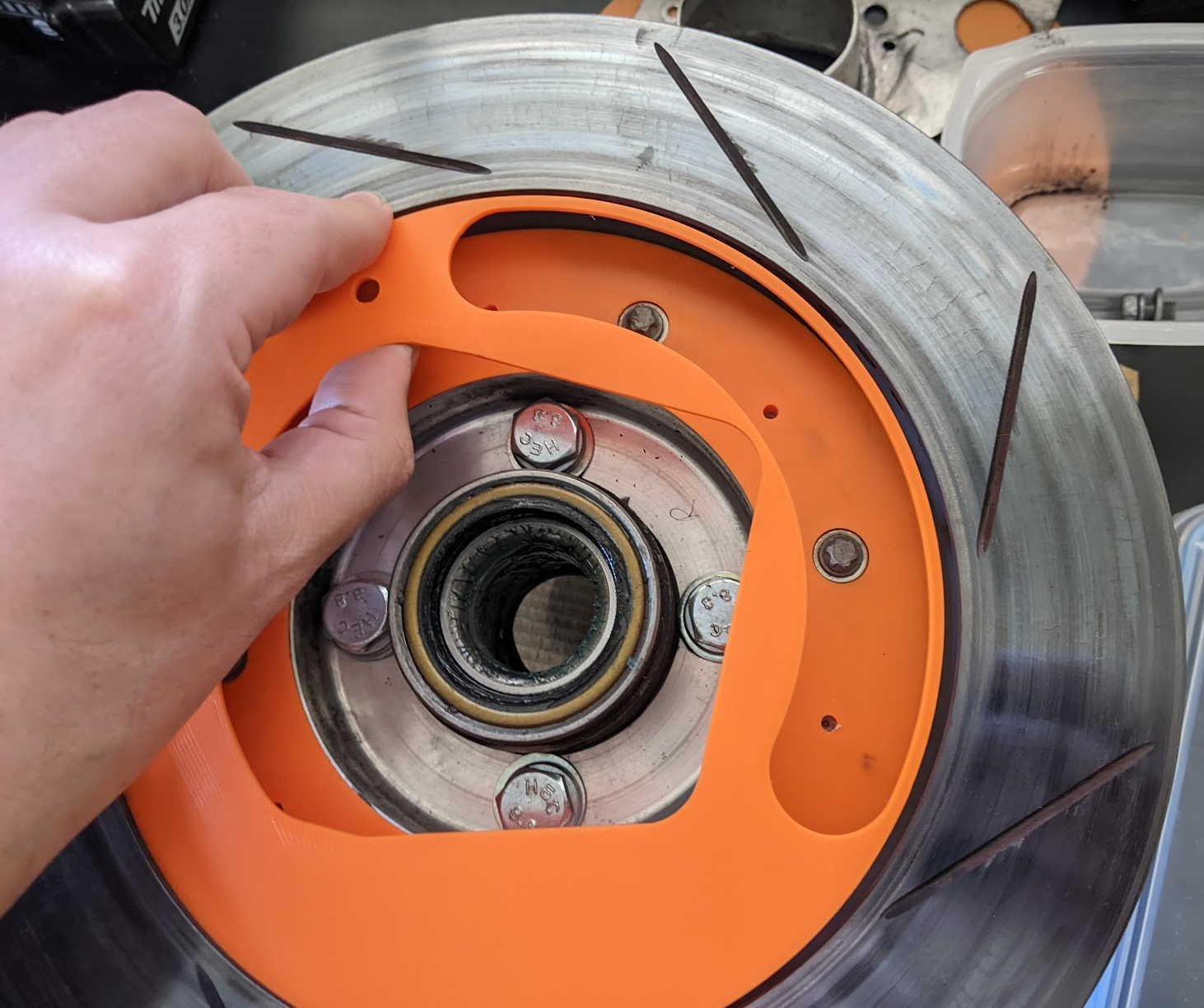
Current hole size is 1500mm2, tube is 2.5" (3100mm2) however the inlet on spoiler is 2" (2000m2) New hole size is 4000m2, I'll be upgrading the tube to 3" (4500mm2) and the inlet to match. If i was 3d printing in metal or maybe doing it carbon fibre it's possible to get the hole on the plate to 4500mm2 but it's a more complicated shape. So i really do need to increase the hole size, no room internally in the rotor for vanes, only have less than 20mm to play with and there is bolt heads in there as well. also don't think it would help, i need to get air into the center of the rotor and let the rotor vanes then pull it out. I'm already running maximum disk size you can in a 13" wheel. there is 2mm of clearance between caliper and rim, to go thicker would require new calipers and going to larger rim. Background: I'm warping rotors as the hats have not been designed large enough and so the air is going straight through and up the outside face of the rotor, I have a solution for that, but that means any air will escape where this plate sit, and that means there will be cool air flowing over one face of the rotor, creating a temperature differential which will cause them to warp again. At $600 per rotor I can't afford to warp another set (If i can get temperatures into the correct zone they will last many years), so I have to make sure the air goes out the vanes evenly, hence the tight fit, but then I need to ensure enough air gets in, and larger is better in every way as you can always blank off the inlet. I also only want to do this once, so prepared to spend time/money getting it right. -
Advice required: Making complicated brake duct out of aluminium sheet
Hyperblade replied to Hyperblade's topic in Tech Talk
Very true, good idea on an approach. Sometimes when you racing cars with 500hp the braking zone is the only time you will ever get close to feeling like you can pass them -
Advice required: Making complicated brake duct out of aluminium sheet
Hyperblade replied to Hyperblade's topic in Tech Talk
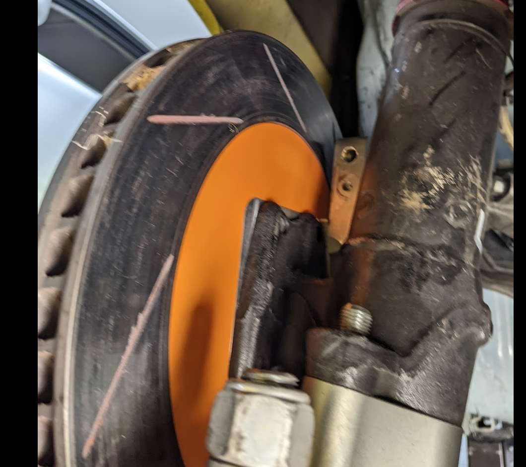
Always open to feedback. Old one seemed to be ok for 5 + years? It's AE86 front struts so hose goes straight to chassis mount, so hose is taking all the flex. There so some pressure on the plate, but there is a tiny bit of flex in it? I am considering bracing the inlet against the strut to take any movement out of it. Yeah the aperture is one concern i have, but i really need the biggest hole i can get. (Guess one option is to get the whole thing made out of carbon) Air is coming in from the strut side from high pressure zone on the front spoiler through the orange pipe. Race car only, rotors are seeing sustained 600c +, this is a 267mm x 25mm disk all under a 13" rim with a 12 lap race where i'm often in traffic, so getting rid of heat is a big problem, so it needs more than your typical race car. Good idea! hadn't considered that approach.
-
I need to go from this hole at a 45" angle up, right and inward towards engine bay and then adapt shape to to a 2.5" or 3" outlet to attach the hose on to, space is very tight. Orange plate will be 2mm ali, currently thinking of having it laser cut instead of doing it by hand. What options are there for achieving this relatively quickly and potentially at home? One I option i had thought of was to 3d print the inner and just hammer the aluminium around it, then get the seam welded (or try to do it in one piece), either way I would probably use a separate ali ring for the hose to clamp to. would end up being welded to the plate 2nd option might be the same inner but get someone to lay up carbon fibre around it (don't know anyone who does carbon fibre, or what that would cost me), but high temp area and not sure how specialised that is. I can't see fibreglass withstanding temperature? Any other thoughts on how to solve the problem?
-
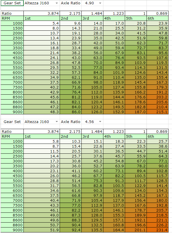
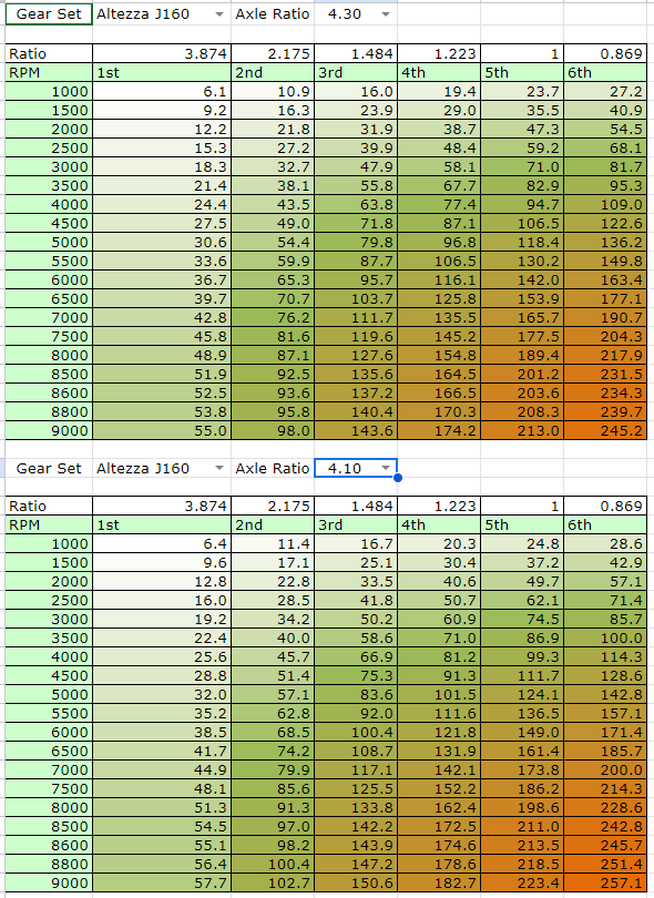
So the only TRS tyres you can still get secondhand from the series are the old rears, (now the new fronts) which need 10" wide rim, so most cars require substantial modification to run them. Those charts were based off the smaller TRS slicks that runs on 8" wide wheels. so you need to think carefully about what tyres your going to run, it may be that 15" might be the more economical option (even though I don't like the look of them on old cars) For grip, you will be wanting to aim for 185 - 200kph at the end of the straight which should be doable with your weight and power. I went with 2nd-6th gears which meant launching in 2nd and using 3rd for hairpin 4-5 everywhere else then 6th for straight. But the alternative (and much nicer if you street drive) is to use 1-5th which can be beneficial for N/A cars as not using overdrive 6th. Here's some diff/speeds (based on 54cm trs tyres) to give you an idea of where it would sit You have lots of revs available which gives you a few options (let me know if you want me to calculate any other options).