Adoom
-
Posts
2196 -
Joined
-
Last visited
Everything posted by Adoom
-
Can a 5 rib poly-v belt be too tight and damage the alternator bearings or something? Or are the bearings stronger than the belt? I am running an alternator only setup on my 1UZFE, so there is no tensioner. An internet person recommended a gates stretch-fit belt of a particular size that fits. I looked up the special tool used to install the stretch-fit belts then made do with random stuff that was the appropriate shape. I got the belt on, but it's pretty dang tight. Should I be concerned for my alternator?
-
Pretty sure I read somewhere that Aeroflow recommend clamps on their pushlock fittings if it's over X degrees hotness. EDIT: LOL just noticed I have basically just said the same as Cletus
-
Is this stuff all good for EFI hose? It does say unleaded gasoline and 290PSI, so I'm thinking 'Yes'... https://aeroflowperformance.com/af500-08-3mblk-8-1-2-black-push-lock-hose
-
There were indeed two sticky injectors. I ran the injector test again, and two of them were real quiet. I tapped them with the socket extension a bit and they freed up. So now it runs way better. I took a video of me fumbling with the ignition one handed to start it and make vrooming noises. I also installed the 'rest' of the exhaust, so now it reaches about halfway down the gearbox. https://youtu.be/K9sr3xajSOE I thought about using the original copper radiator, but when I had a better look, I found that the fins were disintegrating. So I've ordered a radiator from Fenix. Ouch, my wallet. After lots of looking at radiators for specific cars and having no luck, it turns out their universal medium radiator is within 5mm of the oem radiator. It also has the same type of mounting flange down the sides, I just need to trim it and drill the holes, then I can use the factory mounts.
- 191 replies
-
- 10
-

-
Thanks, it feels like I passed a milestone. I should probably move on to wrapping the loom with the expanding mesh sleeve stuff I bought yonks ago.
-
I revisited some of CarTuneNZ's videos. Extremely fortunately for me, he has a series of videos on wiring and configuring the ECU for exactly my setup. The issue was the base timing, it needs to be changed for the COP setup. I also hadn't configured the idle control So now it runs! Quite loud because it's only got headers. I can't really run it till it warm because I've got no cooling system. It sounds like it's running a bit rough. Maybe some of the injectors are sticky? It has been sitting for several years...
- 191 replies
-
- 13
-
-

-
Sayf Tea No leaks. Didn't die. No fire. Didn't want to start though. It would just do a random cough every 2 or 3 seconds. I assume it should run, the tune is from Sheepers 1UZ when it was still standard. All I've done is modify the config for COP. I guess it's the timing??? Maybe... But I don't have a timing light. I didn't leave the fuel in the bowl.

- 191 replies
-
- 12
-
-
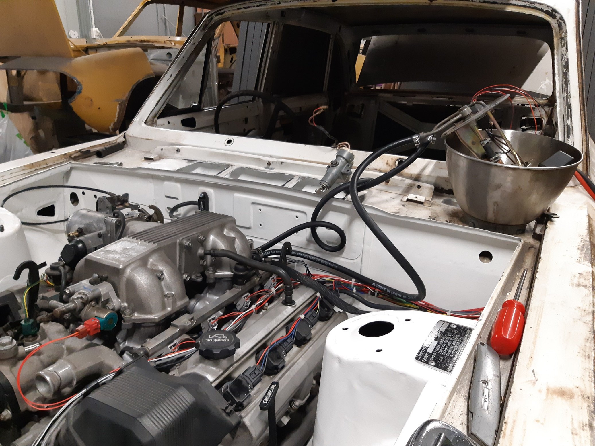
I'm keen on modifying something from another car and replacing the pump. Those aftermarket ones seem excessive for my application. Does anyone know of a suitable doner that is all metal so I can modify it easily? I suppose I could just make it all from scratch. It's just a flat plate with some pipes and a bracket thing.
-
Has anyone installed a in-tank efi pump into a fuel tank that did not have one before? I'm considering using an in-tank pump on the triumph, for the 1uzfe. My reasons are so I don't need to find an external mounting location and avoid having a surge tank and lift pump, also I would assume it's much quieter(because not-racecar). Is it straightforward? How do you deal with fuel surge? The tank has no internal baffles. What about the height of the tank? The oem stuff I have seen photos of look like just a big plastic thing with everything contained within it, I suspect I cannot modify that for height, or make use of the included float level. Should I just use an external pump and mount it under the car, using the OEM outlet on the bottom of the tank? I've finished the ecu wiring and want to test start the engine... but the old external fuel pump I had was fuckzorred(I think the E85 ate it) so I need to think about a new pump now...
-
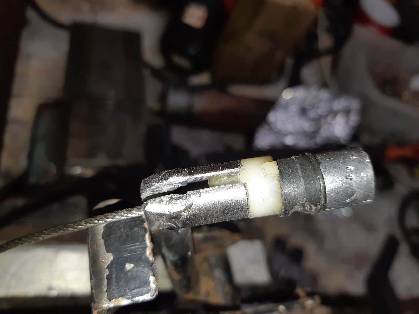
Turns out... lead is easy to melt. This was the first attempt. I pulled real hard on the other end of the cable and it pulled out. Second attempt, I preheated the mould with the heat gun and also untwisted the cable so the wires were all separate and splayed them out. This seemed to work, seems much stronger. Glued an extra appendage on the triumph pedal so the toyota cable bits fit. I did check that it opens the throttle all the way. More than all the way... But the pedal has an adjustable stop, so I adjusted that.
- 191 replies
-
- 24
-
-
-
Actually, this looks promising. https://www.aliexpress.com/item/1005002602810952.html?spm=a2g0o.productlist.0.0.257d6ddekfRGNd&algo_pvid=d840d349-13ad-42b0-a9bb-c5aa26c06c47&algo_exp_id=d840d349-13ad-42b0-a9bb-c5aa26c06c47-11
-
If anyone has links to part numbers for common OEM connector terminals, that would be super handy. I know you can get them from places like RS components, but it's often hard to identify them from the one image they show you.
-
Please tell me you have a plan to narrow the track so it's the same as the maxi. I think a stealth look would be cooler than MASSIVE arch extensions.
-
Mine is one of those WTF does this even fit super skinny allen keys ground to a long chisel tip. I found that it works better than wire because it's stiff and won't easily bend.
-
I've been doing the wiring. It's not an exciting thing to take photos of. I need to relocate the battery in the boot and I'll run the cable inside the car, so I decided I wanted a through-bulkhead stud thing so I had power right beside the fusebox/ecu and in the engine bay to connect the starter cable to. Googles through-bulkhead stud thing. $50!!! I'm sure I can make one for less than that. So I spent $26 on a short bit of 20mm brass bar. I tell myself I'll have lots left over for something else. I already had a big big of acetal I could use for the body. So I spent maybe an hour on the lathe making round things and round things with holes in. To cut the thread... I initially attempted it with my cheapo 'Frost' die, because brass is 'soft', right. And it was entirely useless, Massive amounts of effort required to cut a single thread. So I spent $24 on a volkel die.... plus $6 shipping. I've said it before... damn these are good. It's so fucking sharp, I could just about start the thread holding the die in my hand! It was too big for my die holder... so like a barbarian I used vice grips. Those small screws are countersunk so they don't end up being made live.
- 191 replies
-
- 13
-
-
Too late now, but I reckon citric acid would have worked on those steel wheels. Citric acid is cheap, you get it in powder form. I think I got my on trademe. A big bulk bag, not the teeny pots used for making food things. Or electrolysis would be safer, no chance of leaving it in too long. Also cheap. In both cases you need a plastic thing you can submerge a wheel in. Then you give them a rinse and wipe with a scourer pad. Nice clean metal, until it dries and immediately flash rusts.
-
Just for the on hold bit... Don't listen to that guy at work. You have to keep renewing the 'on hold'. If you don't, you will get a bill from NZTA for unpaid rego from the date the hold ended. This happened to me. AFAIK, to change the rego class, you just tick a different box on the rego form at your local rego form place vtnz whatever. I have not done this.
-
What's the deal with factory quad headlights in a car made in 1971. Can I have all four doing DIP and all four doing High beam? Or does it have to be only two on DIP and four on High beam?
-
I think I may be owed an icecream. A photo will be sufficient.
-
I have the same one as @cletus. I could definitely do with it being a little wider. It's not quite big enough to fit the engine crossmember in. I cut a hole between the gloves and siliconed in one of those cheap LED floodlights. Now I have issues with it creating shadows, so I want to put another one in the top. I made a cyclone dust collector out of a 20L bucket, some ~50mm plumbing pipes and my old vacuum that had lost all of its wheels. The bucket lid is thin so I screwed a bit of wood to it to have something to glue the pipes to. You put a straight pipe in the center of the lid, stick it into the bucket a bit, not flush with the lid. This goes to the vacuum. Right on the edge of the lid you put a 90 deg bend(inside the bucket), point this so the air and dust goes around and around the walls of the bucket. The other end of this goes to the cabinet. It seems to work well. I definitely must try what @~Slideways~ did with the pickup.
-
I have a 70 Watt one. Its original purpose was to power a computer fan to try ventilate a shipping container. Now it lives on the ride on mower. I used to leave it attached all the time, but it eventually boiled the battery... over several months. Now I just stick it on every now and then.
-
So I started looking at the Triumph wiring loom to work out how I will connect the Link ECU loom to it. Lucas, the prince of darkness apparently did not believe in fuses or relays. There are 3 fuses and a relay for the horn, that's all. I've found some dodgy repairs to the instrument wiring. And someone had put in a relay for the headlights, but it's really old and gigantic, I had assumed it was an external voltage regulator before investigating. A section of loom has also been lengthened, with different colour wires... I haven't worked out why. To sort out the dodgy repairs I've had to unwrap the whole loom to decipher the how and why, so since I've gone that far I may as well modernise it a bit and put in a new, larger fuse box and some relays to take the current load off the old switches. The OEM wiring for the Oil and Brake warning light is LOL. (The brake warning is if the front/rear circuit fails.)The lights are wired in series for power, but each has its own earth through their sensors. There is a description of how they work in the factory service manual... Ignition ON engine not running: Oil light "ON FAINTLY", Brake light "ON FAINTLY" (apparently so you can check the bulbs work) Engine running: Oil light "OFF", Brake light "OFF" (Yep) Engine running brake circuit failure: Oil light "OFF", Brake light "ON BRIGHT" (Cool, makes sense) Engine running low oil pressure: Oil light "ON FAINTLY", Brake light "ON FAINTLY" (Ummmm. What!? I know they are "faint" because they are in series, but surely there was a better way to do this.) It does literally say "FAINTLY", which in real life is probably so dim you can't tell it's on, because Lucas. However, I've got a oil pressure sender for the ECU, so the oil warning light will be controlled by the ECU. I am undecided if I will retain the brake warning light, as far as I can tell many models didn't have it. I also had trouble finding a wiring diagram that included the light and sensor. Some diagrams listed the light and sensor as items 51 and 52 but they were missing from the actual circuit diagram?! I eventually found it in the factory service manual under "Left hand drive models only"...??? If I decide to keep it I have loads of spare inputs/outputs on the ECU, so I could connect the sensor to the ECU and get it to control the light as well.
-
I'm going to rewire the headlights on the Triumph because NO FUSE and NO RELAY, all the current goes through a 50 year old switch made by Lucas, the Prince of Darkness... With headlight wiring.... when you use high beam, should the dip and high filaments both be on, or only the high beam filament?
-
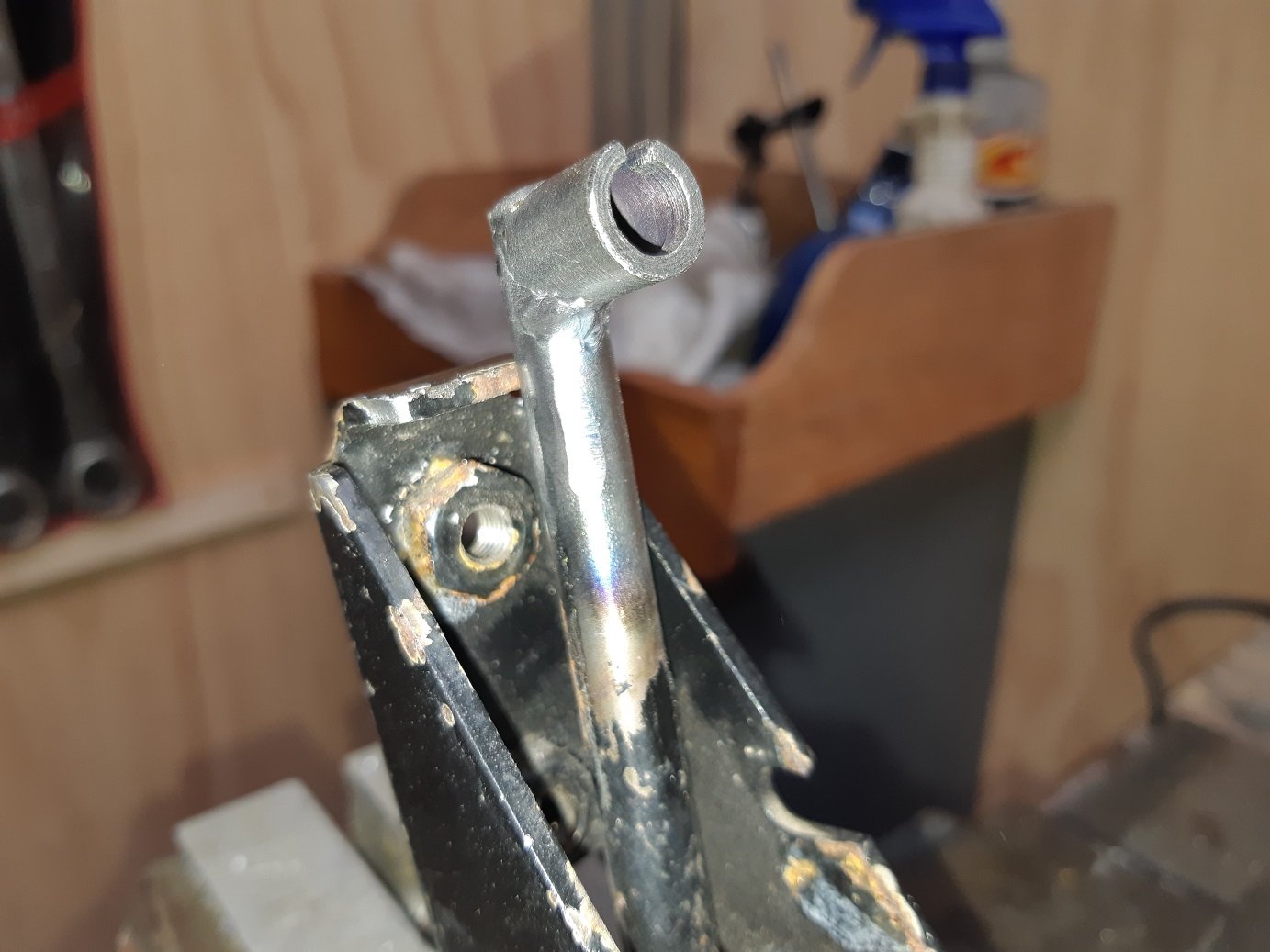
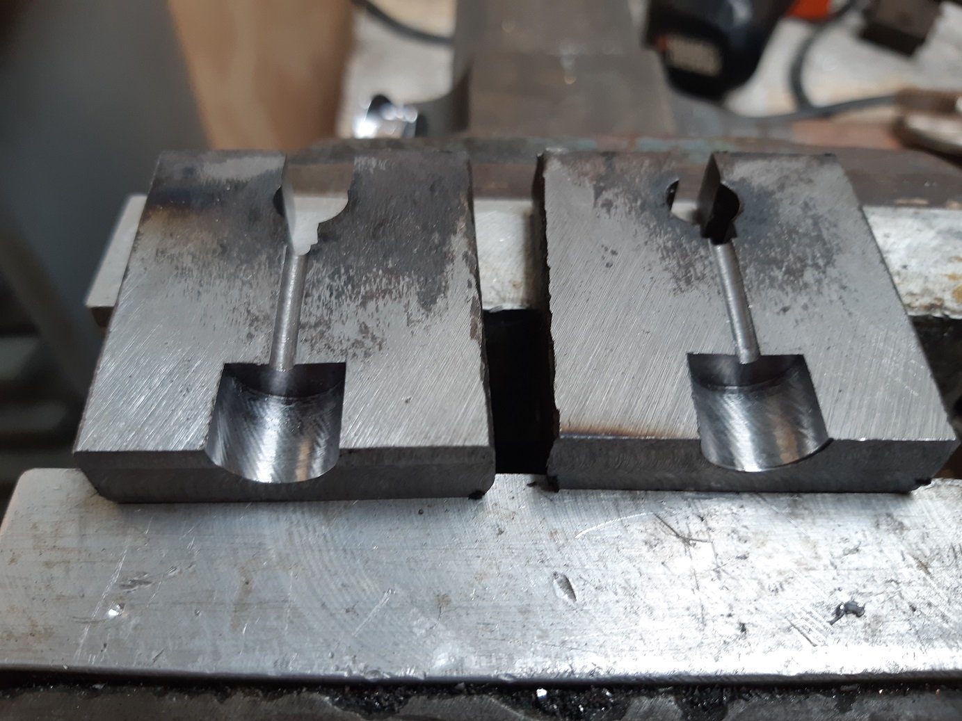
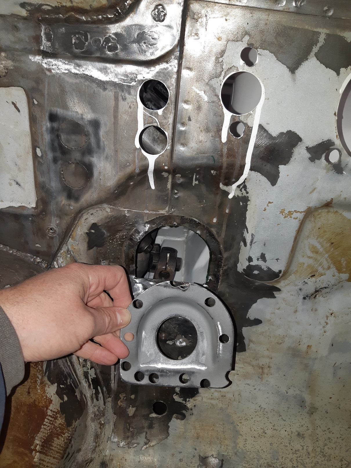
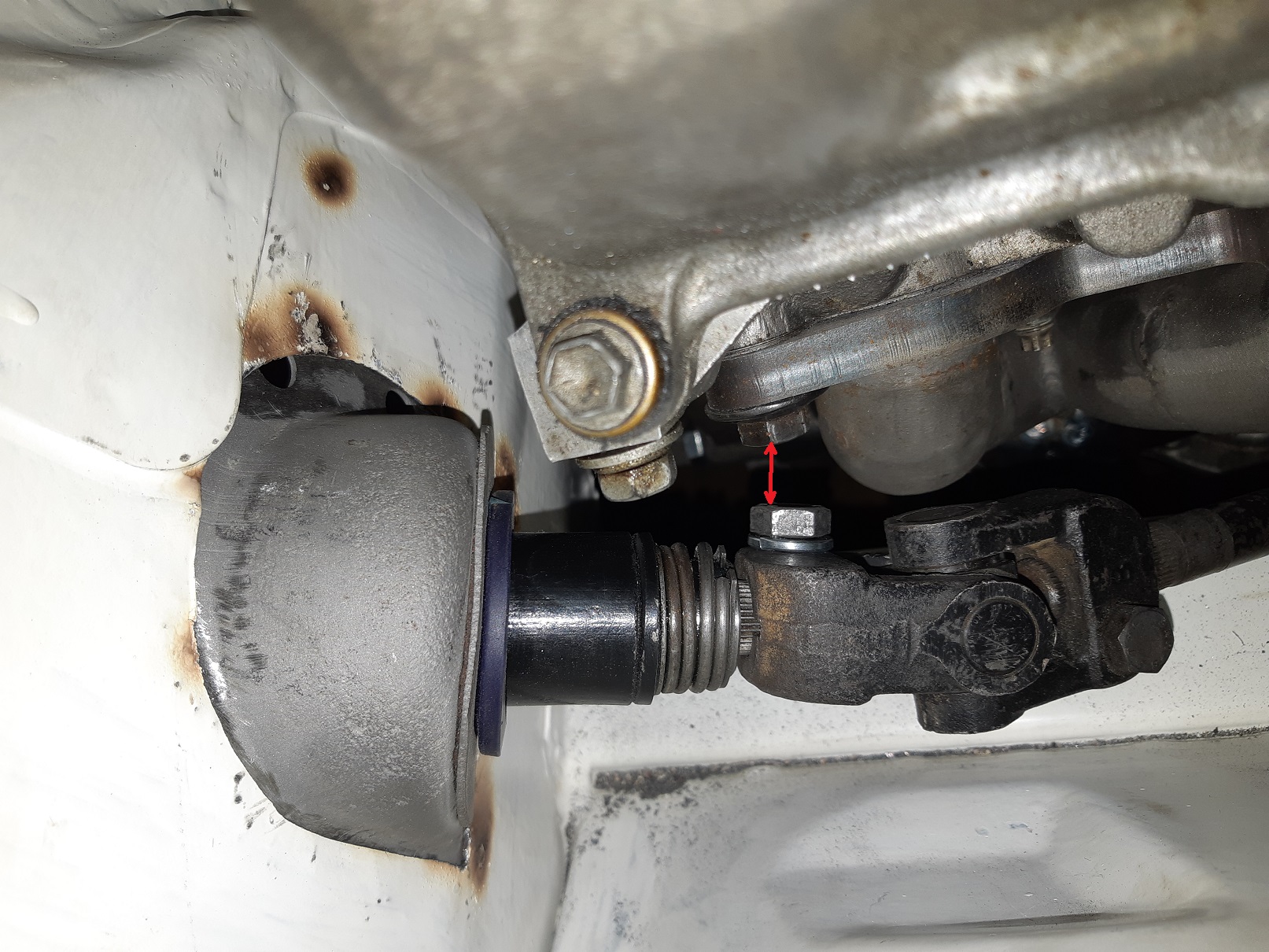
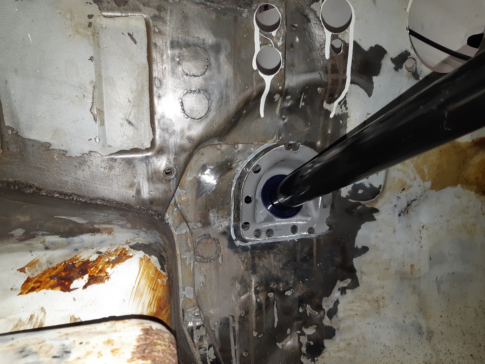
So I've been fighting for clearance for the steering off the rear stud for the exhaust manifold. I first tried replacing the stud with a bolt so it was lower profile. I still had negative clearance. The universal joint has a bolt that goes right through with a nylock nut which sticks out a fair bit. I looked at my starlet, and there is no nut, one side of the hole is threaded so you just use a bolt. I decided to replicate this method. I drilled and tapped it to the next size up UNF thread(I didn't want to mix and metric and imperial in the same assembly). But now the U-groove in the end of the steering column was slightly too small for the bolt to slide through. So stripped down the column and put it in the lathe. Fuck all needed to come off, it's now just the right size to thread the bolt in by hand. I painted it and regreased the bearings too. That got me down to zero clearance... you can turn the wheel, but the corners of the bolt heads just clip. Time to get drastic...er. Move the lower mount of the steering column over. To avoid making a mess of the panel behind, I used the flap disk until it was wafer thin then peeled it off. This intact lower mount is from the rusty car. I also kept part of the panel from the other car to use as a cutting template, and later I'll make a filler piece from it. It only needed to move a little bit, less than 10mm. Using a set of drill bits to measure the gap, the closest it gets is 9.5mm. The intermediate shaft now touches the chassis rail. When the engine is out again I'll make some room there.
-
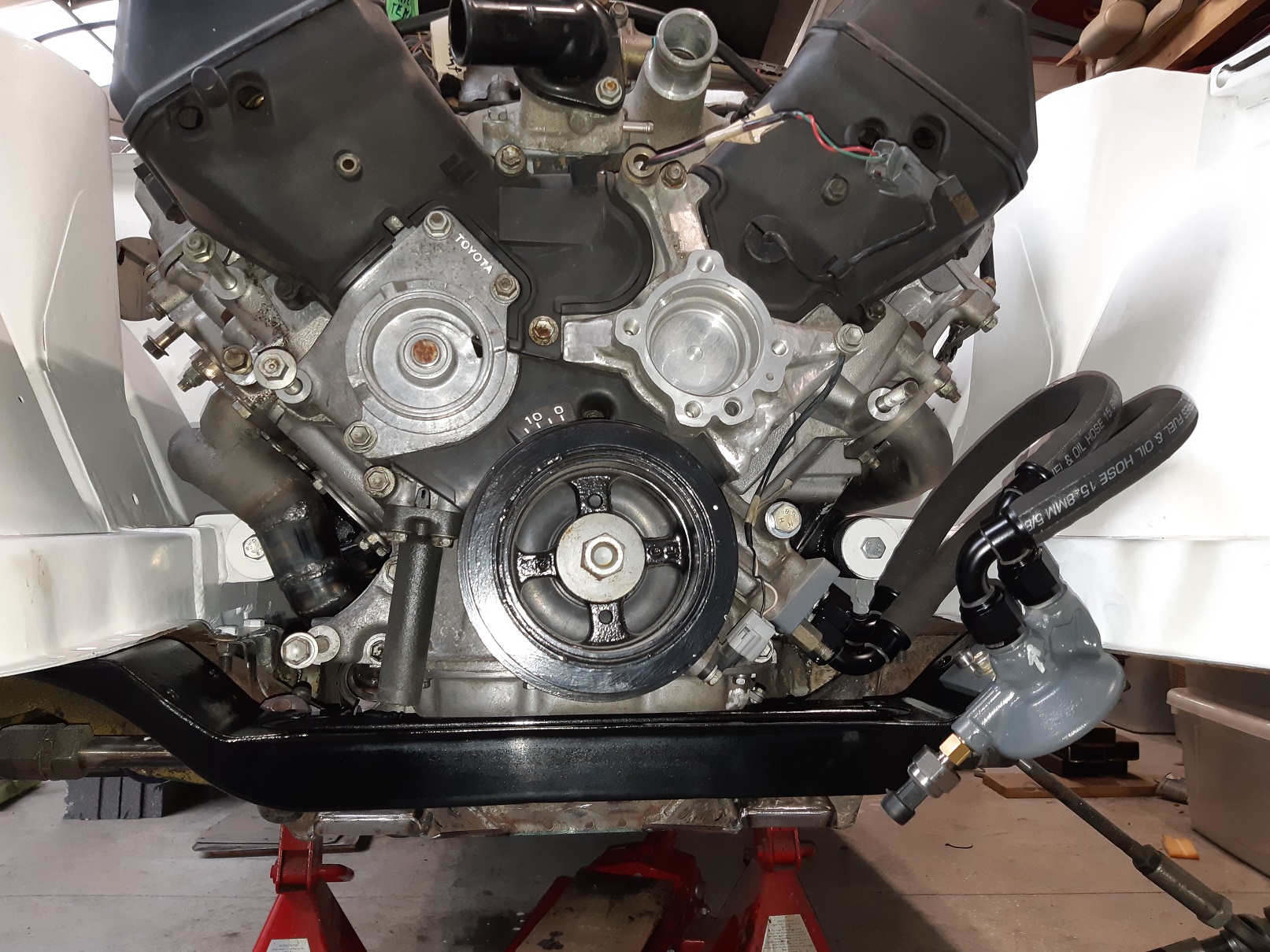
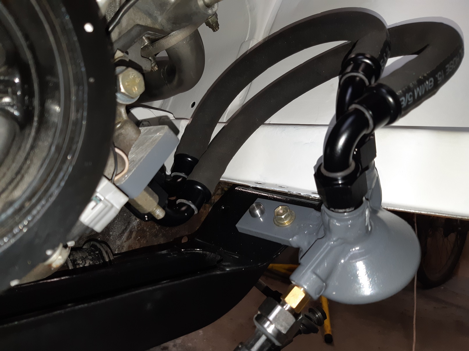
Sorted out the filter mounting. I later realised that the hoses were the wrong way around(when I sprayed myself with oil removing the filter to check if it was circulating). I'm going to mark it with bright paint so I don't make the same mistake again. I had initially intended to point the fittings at each other, so the hoses could be really short, but that didn't work out. When I weld the front panels back on the car, the filter is shielded by those.
- 191 replies
-
- 13
-