


flyingbrick
-
Posts
11652 -
Joined
-
Last visited
-
Days Won
2
Posts posted by flyingbrick
-
-
On 01/09/2021 at 08:27, Muncie said:
Hey mate the way I read that is-
That charger needs the batteries separated for it to work eg: you could put an isolation switch in your link between your 2x 12v batteries then yes it'll charge them independently, but you would then need to disconnect your charger when you go back to 24v re-closing your link.
It will try to balance both batteries to the same voltage but depending on your batteries internal resistance they will need different charging rates to achieve this, Eg one might charge at 3amps the other at 4 for 6 hours to reach 14volts or fully charged.
*My explanation may be way off btw* more technical people can confirm or deny this.
It clearly states the 24v information. Wouldn't do this if it only charged 12v batts.
-
Should have whomped him one first for being an giant D.
-
On 31/08/2021 at 18:10, ThePog said:
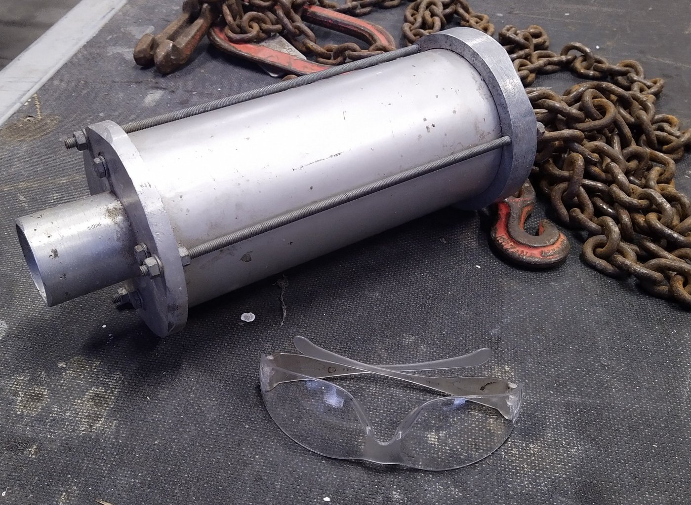
Me and a mate built this at Uni as part of the design stuff for a competition, we didn't actually win on the day due to the way the results were calculated but we went twice as far as any other entry and i think they still use it as an example...

Firstly, this is how it works, the basic setup. The red is a bit of 5mm polyurethane, all else is aluminium;
Then you pump air in which seals the barrel and fills the outer. Once it is pressurised you remove the pump, the valve actually has nothing in it so the removal acts as the trigger;
When the valve is removed the pressure on the polyurethane seals the valve/inlet and all the air rushes out, pushing whatever is in the barrel with it.
And as promised, a video of it in action and some fucking dodgy editing for lols.
I require pics of golf balls being fired through various materials plz. Car doors be good
-
 6
6
-
-
Fark that's genius. A bullpup spud gun
-
2
-
-
Hey man I have some joints, pipe, weld in threaded ends etc here for the ute that won't be used for years (ever) if ya still doing ya tramp bars after lockdown I could visit with it all, you mind find some stuff useful
-
shit that is epic, I'd missed tons of updates so that was a cool surprise.
-
Good to see ya moving on this again

Hope you are enjoying the new job!
-
1
-
-
Good work man!
Hadn't seen this thread before today- was a good read!
Pretty cool seeing your welding improve so much over the 4 pages.
-
Dude... Nice bike! Doesn't get much better than that. Doubt it will take you long to get it running like new. That color and tail looks great in my opinion..
-
1
-
-
On 15/08/2021 at 19:42, Roman said:
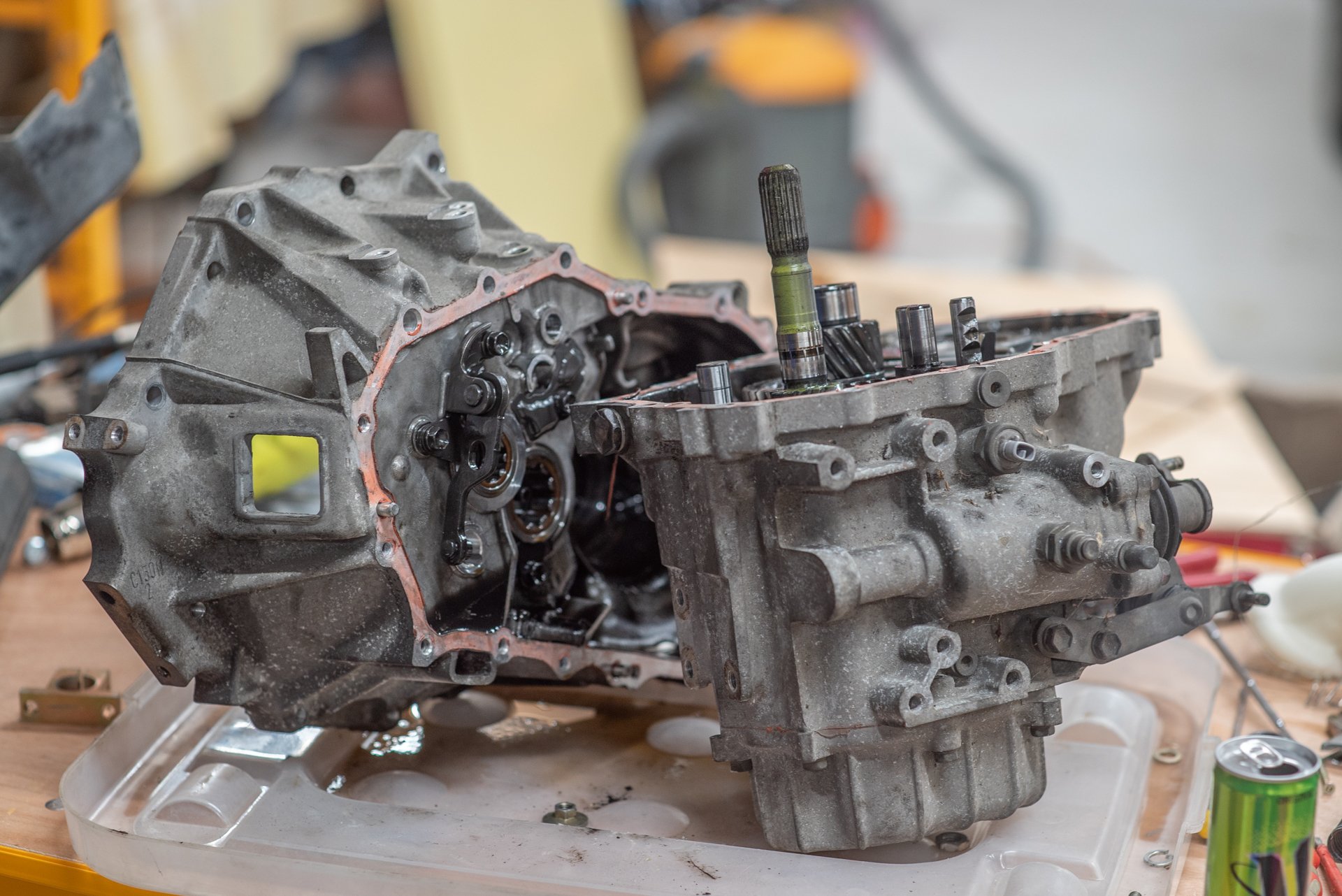
So I put on my brave pants and took my brave pills and pulled my spare gearbox apart...
Too easy!
I think I've just managed to get some PTSD from the complexity of J160 boxes. But this was piece of cake.
I toyodiy'd the gearbox parts to look for any differences, found that the bearings and shells have different part numbers.
Some more digging and I found that they have a different size or taper on the bearing and shell, so you need to match them.
Otherwise you get this situation where the shell doesnt sit flush to the bearing:
So this week I'll pop over to my Dads place and use the gear puller and press to swap the bearings over, then its fairly easy looking to get it all back together.
It turns out that some variants of the C series box have a 6 bolt crownwheel, luckily both the AE111 torsen center and the RS box have the 8 bolt pattern.
Cant wait to get this new box in, will be awesome.
I've also been thinking of some methods for half arsed launch control when I dont have a non driven wheel speed signal.
I have setup a timer that resets to zero when TPS is over 80% and vehicle speed is zero.
So when the vehicle speed goes over zero, the timer advances and the engine is allowed to accellerate at a specified rate over that time.
Then once the timer reaches 4 seconds you get the normal rev limit from then onwards.
The other axis will be an input that will come over canbus from my dash, so you can adjust how aggressive it is.
I'm not quite sure what sort of time period will be needed yet for this to work nicely.
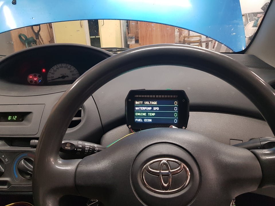
Oh yeah and bodged together a little canbus dash to show some things that you dont get on the main screen.
Graduated shift light is pretty sweet.
But the main thing is to give some peace of mind about the electric waterpump, with some big flashing warnings if it fails.
Lol.. Just bodged it together... Damn, that sort of DIY is so far out of reach of the average person it's crazy lol.
Love it.
-
2
-
-
@CUL8R damn this thing looks tough!
-
2
-
-
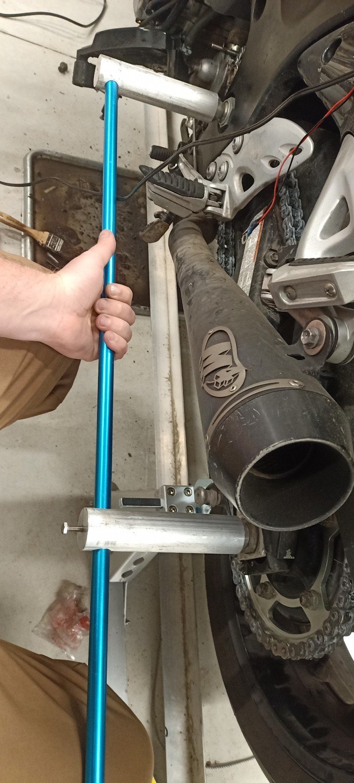
Pulled off fairing and old sprockets. They were both pretty worn on one face each. Surprising because the rear axle was perfectly aligned with its notches.
I asked a mate with a busa(he has a couple including a bking and a turbo busa drag bike) , he uses a laser thing to align his bike and tells me all of the marks on these bikes are wrong from the factory.
I Google it and he's right. Apparently there's quite a few different models of bike with shit house marks.
I managed to find some decent info about how many race teams align their rear wheels then gave a basic drawing to @Kimjon. Within a few days that bloody brilliant chap had machined up the bits for me. I skid them onto half a flounder spear shaft and boom, foolproof and extremely accurate alignments every time.
The cone ends center themselves into the swingarm pivot and the rear axle, you just lock the tool and compare one sides measurement to the other side.
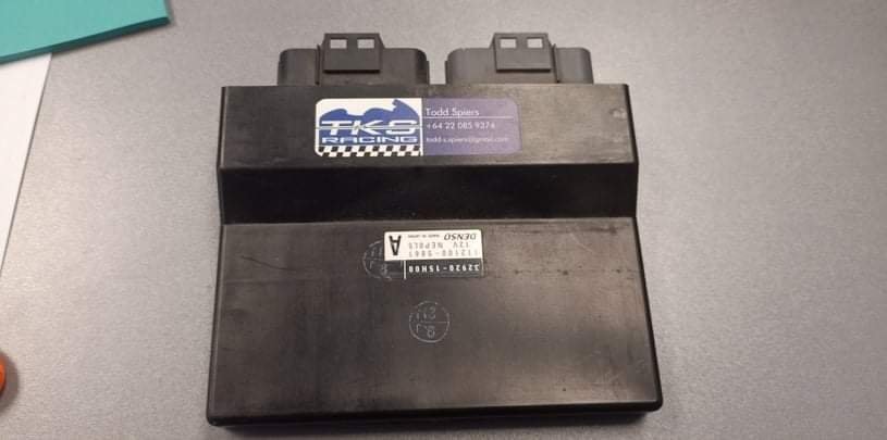
And on Tuesday I sent off the ecu to the same bloke who gave alignment advice. He flashed the ecu for me and put a sticker on it.
These computers are pretty advanced and have nearly as much tuneability and functionality as a modern link. It adjusts 8 injectors with maps for each of the four cylinders, fuel and timing depending on which gear you are in, which power level you have selected (basically three different sets of maps which you can flick between on the fly to change power levels or whatever else you want to change maps for).
Its also completely tunable with just a basic cable and some software (which isn't that expensive).
But cheaper than that is just having him to do it. He has a very popular set of safe maps that make it a bit smoother, a little more powerful, more free revving etc plus turns on fans at a slightly lower temp. These bikes are so popular around the world that there's a pretty comprehensive recipe to get them running their best.
-
8
-
-
Yeah what dave said.
Its actually easier than it sounds.
The most critical thing is to wax the Hull and flange material quite a few times prior to putting any epoxy near it. Fucking that up will ruin your Hull pretty quick. Use a mold release wax, rub it on, let it dry, buff it off and repeat until you cbf repeating it any longer.
Also, get some digital kitchen scales to help with measuring out the resin accurately.
-
On 09/08/2021 at 14:18, chasinthemirage said:
I recently bought this vacuum formed hull off trademe. It's quite a nice wee hull but is fairly flimsy as it's only plastic. I want to make a copy of it in fibreglass so it's a bit tougher. How would you guys recommend I go about making a mould? I've been reading up on it but keen to hear some real world advice as there's an overwhelming number of options.
It's part of a vintage kit so I don't want to destroy the original hull in the process. It would also be a bonus if more than one hull could be made but it's not essential. I've removed the motor mount, rudder post etc and will patch the holes up.
At this stage I'm thinking the way to go will be to clean up the inside of the hull, apply some sort of release agent and then fill it with plaster of paris/liquid latex etc to form a plug. Then fibreglass over this plug to make a hull.
Does this seem plausible to you guys? And if so, what would you recommend I use to form the plug? Thinking I'll just use a fibreglass kit from Bunnings for starters as it seems a pretty cheap/easy way to purchase everything I need to start out.
Hey man.
No, don't use a plug to make your new hulls. You will end up with a nice Hull interior and a shit exterior which requires untold hours of filling and sanding.
You need to make a normal mold of the exterior of the Hull. In practice, once you knuckle down and do it this won't take long.
I'd start by turning the Hull upside down and gluing it to a flexible sheet of something like coreflute. You could slice one side of the material along it's grain so that it flexes easily in one direction but is still rigid in the other. Put the uncut side toward the hull, push it into a curve of the hull (where the deck would usually fit) and glue it firmly to the hull with hot glue so that the mold is formed with a sturdy perimeter lip.
Then seal any gaps or holes with quality modeling clay, smash down some wax and then lay your fibreglass.
Start with straight resin mixed with pigment to make a gel coat (so you can see where it's going), wait for it to firm up until just tacky then add fibreglass tissue, then cloth or mat.
-
1
-
-
On 29/07/2021 at 18:03, NickJ said:
the level indicator can often be wound open to top up electrolyte on stuffed batteries
When I actually looked- turned out kims one just unscrewed too! I topped it up with distilled water- but yeah didnt really seem like it was filling the other cells at the same time. I think I'll try harder to get the cover off.
-
I am still playing with @Kimjons battery. The Bluetooth battery monitor logging is brilliant. I thought my desulphation charger thing only had a set voltage but turns out it alternates up and down for some reason.
It is getting better, managed to actually run a discharge cycle on it yesterday.

-
1
-
-
31 minutes ago, GuyWithAviators said:
Pretty sure I read a yarn on here where someone just cut holes in the top of each cell bank, topped them up and glued the plastic back on. @Ghostchipsor @SOHC probably
I guess you could drill holes in the top- big enough to check level and fill but small enough to seal with Hot glue.
-
20 hours ago, h4nd said:
Light dimmer style? Probably OK, best ask a tame sparky. @UTERUS etc?
Chuck'em in parallel, use sensible fuses, make sure chassis are securely grounded. Insulate them for another layer of safety.
4kW is getting pretty heavy, you're gonna maybe melt your plugs / sockets / wires in the wall / set the suburb on fire / raise the CO2. Maybe get a (safe) current meter so you know how reckless you're being?
I think @NickJ comment may be worth considering. Pneumatic engineer, I ain't
")
I'm running 4000w of heater off a multi plug in our garage- doesn't even get warm
")
Edit. The heaters get warm... the plug/socket does not.
-
 2
2
-
 1
1
-
-
@NickJ that is a brilliant idea! Do the cells all join at the top? EG if I fill up one will it top up the rest?
Also, worth shaking it up first and checking the specific gravity of the electrolyte? (I think thats a thing?)
IF you know more about this than you are letting on, you should definitely share
-
I find battery tech quite interesting for a multitude of reasons. We all have this physical item made out of basic and identifiable materials which is expensive to purchase and costly (to the planet) to recycle- yet repair is largely out of the question. It shouldn't be because a lead acid battery is incredibly basic!
@Kimjons battery bugs me. I can charge it to over 14v (Using bluetooth battery monitor to log voltages is amazing) but then the instant you apply any load it drops to below 12v. The float/indicator is red even at full charge which could simply mean that one or more cells is low on electrolyte- but the battery has a firmly glued down cover which does a pretty good job of preventing any level checks or top ups (without making it look like its been butchered)
TLDR: battery companies go out of their way to ensure these things aren't serviceable. Bastards.
With that said, have had a few good wins with the desulphater (Validated by load testing down to 12.2v and measuring capacity).
-
3
-
-
....... Some people like having a DSLR and wouldn't touch a disposable.
-
2
-
-
Just pop down to the closest machine shop and ask for a price. You might be surprised by how cheap it is.
-
Man drz400's are extremely good bikes, enough power for 100 and overtaking etc and great value.
Knowing what I know now, I'd skip the old small cc stuff and go straight for the newest, most reliable and powerful thing that you are brave enough to ride.
Also, bigger bikes are easier to ride, more comfortable etc etc
Oh and it's great when you aren't adding yet ANOTHER project to the shed and can actually enjoy the bike and travel places.
-
3
-
-
I know that my KTM was the same as those sold in NZ for road use - but because it was made/first soldi n South Africa and not recorded in the system during import- it was impossible.
U might be in the same boat
No idea how you get a custom built registered or what amount of modification suddenly makes it a custom built. If it was easy I could have just said the ktm was a 2020 brick special and got it legal lol


Tortrons espresso CB650
in Two Wheels
Posted
My KTM had a shit battery when I got it and was sometimes a cunt to start.. used to HATE gas stations. Nothing worse than ppl watching you trying to kick start something like that.