Roman
-
Posts
7,233 -
Joined
-
Last visited
-
Days Won
39
Content Type
Forums
Downloads
Events
Gallery
Everything posted by Roman
-
Weld that tach to the 10k rpm mark! haha
-
I posted up the failure on a 2GR group on Facebook, and someone had this to say: So hopefully that's the end of that issue at least.

-
Yeah looks like a little tig blob and will be fine. Time consuming, but cheap and easy fix for everything that has happened. I will see if I can get a head off while the engine stays in the car. I might look at modding the front cover so I can remove it without taking the sump off, as its a major pain. Especially since I'm probably going to need to do it 10x more
-
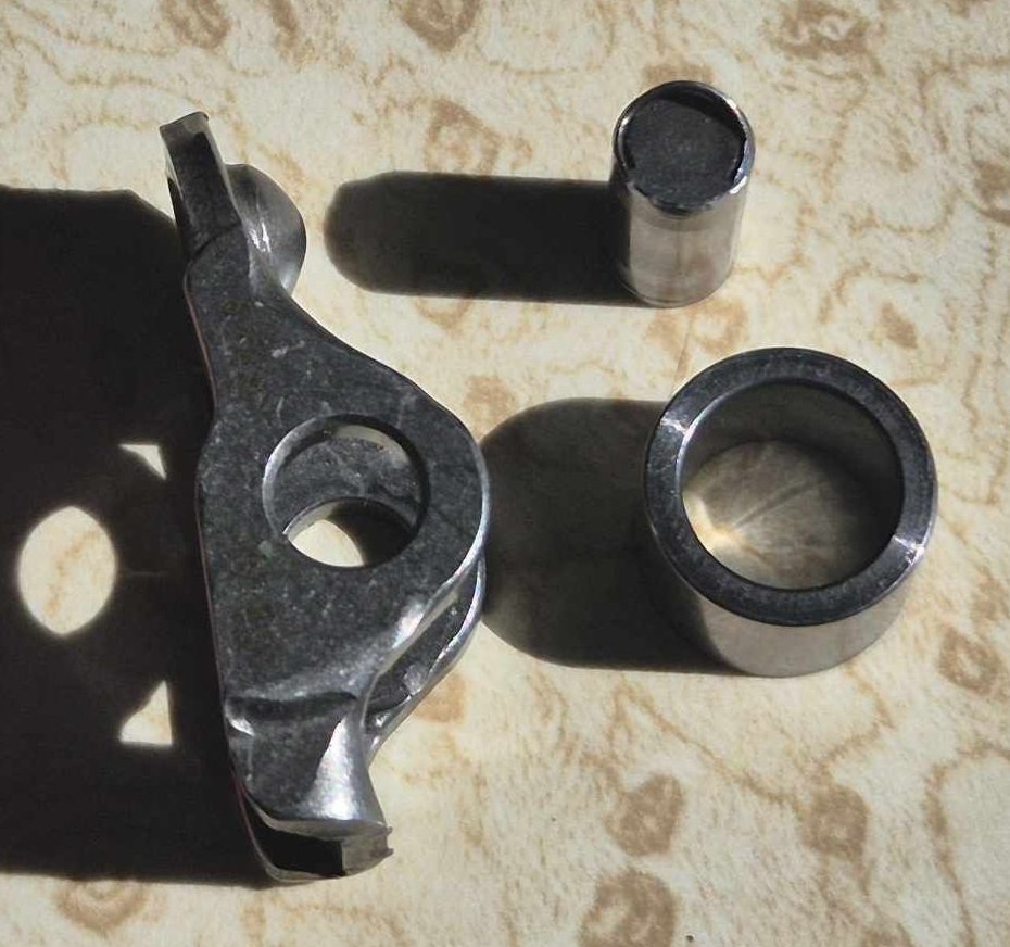
Yeah, they are cheap and common at the moment, and still reasonably low km. So its definitely the intention to buy and wrap up a few whole motors while they're still nicely priced. However they are made right up to 2019 so I'm not anticipating any shortages too soon. Shrike - Those two guys above havent actually done it yet. Frankenstein motorworks will get here. Other guy, I wouldnt bet on it. I cleaned up the busted rocker and had a test to see if it will tig okay. Looks like it will be sweet as they are same material. So one side the pin was high, the other sunken in, and they both tigged up fine. Will just make sure everything is super clean, tungsten is super sharp, and will test on my busted one before piping anything down on a part I'm going to reuse. So all that I have to now, is take the sump off, so I can get the front timing cover off, so I can get the cams out
-
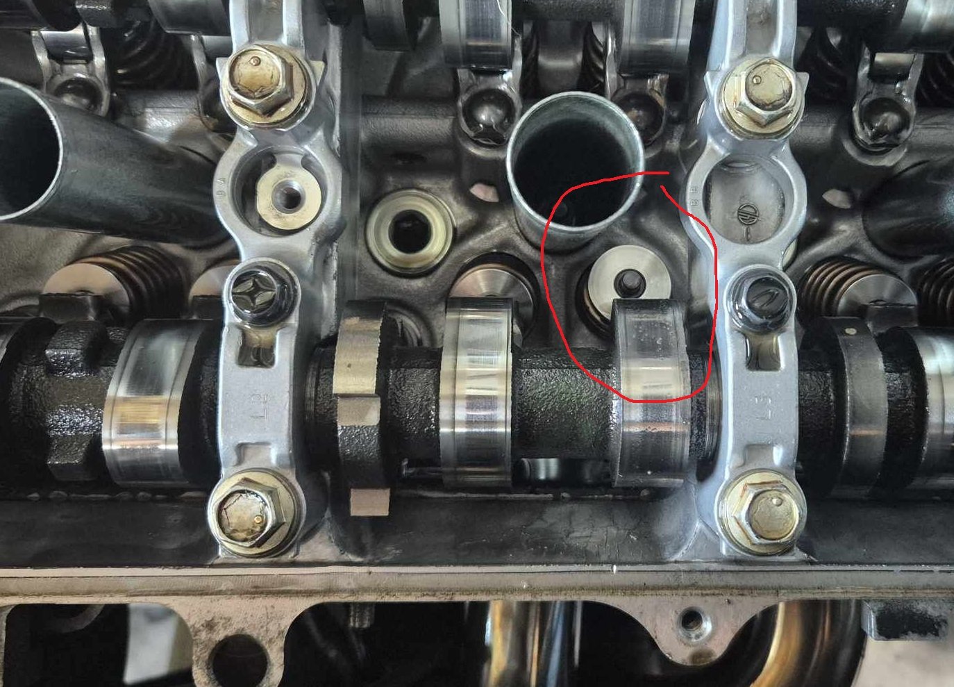
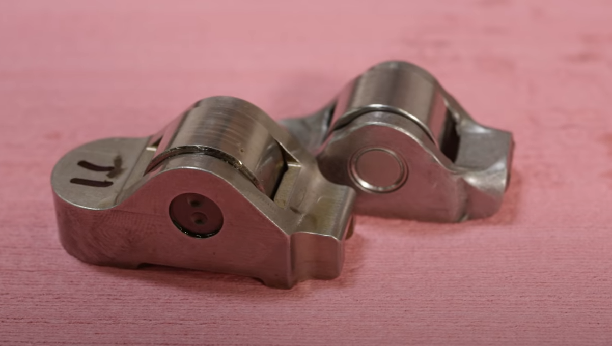
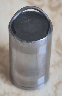
I broke it again.... I was giving it some revs again and running through the gears. Got up to around 8600rpm. Loud ticking noise getting louder, pulled covers off to investigate. Found that one of the rockers had dislodged, but, not really dislodged. The bearing has come out of the center. then after that the rocker likely flew off, and then a valve got bent in the process somehow. So, not hugely bad in terms of engine damage... The biggest expense is time spent replacing the valve. I think the motor I pulled apart from last time at pickapart to get the intake valves out of. Is still there waiting for me to go grab some exhaust valves haha. Although it'll be tricky to get this bent valve out, as it's bent from the top. Might need to cut it off somehow. With regards to a long term fix. Seems there are two possibilities and I'm not sure which yet. Either the pin vibrated itself into the 5th dimension, and just pushed itself all of the way through the rocker one side to the other. Or, the rocker flexed enough that the pin and bearing could come out the top. So will investigate some options to beef them up, but might be time for a CNC project for some beefier rockers. Someone mentioned to me that Papidakis racing was running a 9000rpm 2AR engine, and they have the exact same rocker setup in the head. I watched a teardown video, and turns out they ended up making some beefed up rockers to alleviate a few issues. So that might be best way to go. Also, although it's annoying to have another breakage, reminder to myself that this is what I signed up for. There are plenty of well trodden paths to go down, this is how it goes when there arent 5000 other people who've done the same yet. Engine knowledge is written in blood! Will be interesting to see if there are any signs of deformation on any of the other rockers, they all looked alright by eyeball so far. EDIT: Okay I know a bit better what happened now. So the pins arent even press fit, they are just staked in place. So I can actually slide the pin all of the way back in, very easily if you get it right way around. there is juts a C shaped stake on each side, holding it in. So on this rocker the staking lifted, then the pin could easily slide out. So the pin definitely came all of the way out one side, not flexing the rocker and out the top. So a tiny tig blob on each end might solve it, if I can weld accurately enough. haha EDIT 2: I asked around on a Facebook group for 2GRs, if anyone had had similar issues. Someone mentioned that this is a common problem with the Boxer motors in the GT86, and so the they tig weld the ends, then it's never a problem again. So will proceed as planned!
- 131 replies
-
- 38
-

-

-

-
That looks incredible! Love it!
-
Hey, My understanding is the 4GR, 3GR, and 2GR are all physically the same size. Just shorter stroke and so on internally. So, at last check there are at least 1x 4GR powered car at each pickapart location in Auckland. and a few 3GR. (3 litre version) So you should be able to go eyeball something and measure it. Look on the pickapart website for Toyota Mark X GRX120 (or similar) The rear sump setup is a nightmare though, as is overall height with the standard sump if you dont want to chop the bonnet.
-
Possibly incredibly hypocritical of me to say this. But just stick to the main plan to get the motor running first. Projects like this are good for a spare motor on the side, then swap the whole thing in. But need to treat it as disposable as it's risky. If you've not even driven it yet, you might be surprised that the powerband is how you'd expect it to be if it had VVT anyway. Since its a V6 in a fairly light car. Surely there are big cams or regrinds available for these? Standard cams (and then possibly valve springs) are likely going to be the bottleneck that will make or break the car making power. VVT or otherwise. It will be heaps of fun dialling in the fixed timing engine and getting it running.
-
Alright alright alright Just been cruising a bit since drags pressure was off, but making progress every day. Radiator fan wired up and ECU triggering it. 2-1 section made. Both widebands connected and working. Engine holds water & oil fine. What I've so far made of the exhaust, doesnt leak. Excellent! Has coloured up a bit. I'm stoked that this has worked out well. Mandatory engine noises: Then I bled the clutch, and was making sure gearbox was good and everything working as expected. It selects all of the gears fine, no weird noises or whatever. Clutch works fine and isnt overextending. So I was giving it some big revs while in 6th so there's a little bit of load on it. Then I noticed zero oil pressure. FFS. Maybe spat a rocker or blew up a pulley again? So I pulled engine covers off. Everything is in place, and everything has a healthy looking saturation of oil. Phew. So I'm suspecting that the pressure sensor shat itself, once it first saw some decently hot oil come past. Will be pretty happy if it's just that. Thankfully I can get both covers off both banks, without having to remove any of the intake stuff or take all of the loom off. I do need to undo the clutch MC to get the cover off on this side, but I can easily reach the bolts since swapping to the slightly smaller TA63 booster. Easy as.
- 131 replies
-
- 38
-
-
-

Daves new school holden shambles. Oops Rod knock deluxe today.
Roman replied to Muncie's topic in Other Projects
Nah, it takes time to dial everything in. It's extra hard without some form of launch control that lets you replicate the exact same launch method each time. Because even with that, there are so many variables at play that can positively or negatively affect your launch. Very hard to isolate the effects. Which is part of why it makes me laugh that they ban ethrottle and traction control, for the drag competitions, unless its factory fitted. Like you can have traction control with a street tyre where it needs to stay in this tiny band of rpm to launch good, and any overshoot with the tyre spinning up and your run is toast. Compared to just sending it on a drag slick that has a 5000rpm band of acceptable launch options, and is completely happy to be be spinning 3/4 of the way down the track and still accelerating like crazy. So almost zero point in any traction control stuff unless you're making a fairly massive whack of power. -
Daves new school holden shambles. Oops Rod knock deluxe today.
Roman replied to Muncie's topic in Other Projects
Yeah I've found track oriented semi slicks to be same or worse compared to street tyres. As they generally have very stiff sidewall which is unhelpful. A drag oriented tyre makes all of the launch stuff way more forgiving, like it makes for a way larger window of acceptable rpm/power at which its happy to launch. rather than feeling like you're on a knife edge of either bogging or wheel spin. -
Daves new school holden shambles. Oops Rod knock deluxe today.
Roman replied to Muncie's topic in Other Projects
Was awesome seeing this run! Love it how it has full interior etc, towing a trailer on way there, does its drag day stuff, then back to regular duties. An awesome all rounder. You've done a great job. -
Daves new school holden shambles. Oops Rod knock deluxe today.
Roman replied to Muncie's topic in Other Projects
Another option if you still have leaks, is from repco you can buy gasket making cardboard stuff. Fancy weetbix packet essentially, but might be worth a try if you're still having leaks. There are a few options, not sure if one in particular is better for coolant. https://www.repco.co.nz/parts-service/car-engine-parts/gaskets/permaseal-gasket-sheet-boj-500x500x1-5mm-mp0152/p/A1290061 -
Has been a crappy month in terms of getting car stuff done. Had the dog/cat/finger thing. (wow, that might sound bad out of context) Garage has still needed work. Ended up away for work for about a week in South Island (Which was great! Just not good for getting car finished) Then lingering flu bullshit that has been sapping my energy. Not gonna lie it sucks big time to miss OS drags again. But I guess I'm still on track towards the important part of the project (drawing graphs)
-
Daves new school holden shambles. Oops Rod knock deluxe today.
Roman replied to Muncie's topic in Other Projects
Excited to see this run! Good luck mate. -
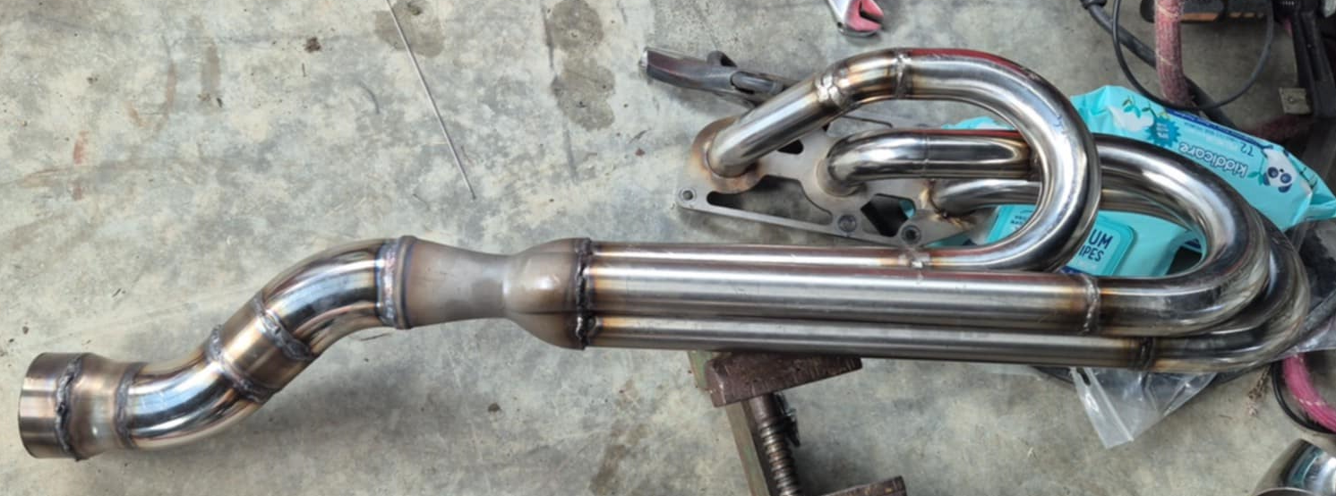
Sorry to everyone that I have blue balled with this project! Over the period of god knows how long it's been so far without any cool stuff happening. I have not yet made good on my promise of doing zillions of rpm with a shitbox wrecker engine. In V6 variant at least. I've been putting in some solid hours to get things finished to try get to the drags. But tonight I've come to see I'm not going to make it. If it was just about getting the car finished enough, might be feasible with some long nights. However it turns out I need an MSNZ license as well as a log book in order to race without wof/reg. I've been going down this road over last few days to try organize it. I paid $70 to join a car club, which is a prerequisite to applying for a license. However it was then was going to be another ~140ish bucks for a license that might not arrive in time. So combined with some extra expenses to get car in a drivable state I'm probably looking at $7-800 I need to pull out of my ass in a hurry. My bank balance got fairly well emptied a week or two ago when the neighbors dog tried to eat our cat. Then the cat crunched my finger when I picked it up. So big vet bill for the cats injuries, and a week on antibiotics and a day or 2 with bandages for me. So as exhausting as it has been pushing hard to get this done. For now I just have a rest. But it's really close to being drivable. Since last post: -Firewall finished -Put crossmember and steering rack back in -fixed gearbox leak (loose bolt) -fixed engine oil leak -finished exhaust manifolds on both sides, down to a finished flange. So they can stay in for good while I make rest of the exhaust. -Got motor and box back in -TA63 booster fitted -Interior started going back in -Started on battery tray -ITBs properly fitted and bolted/sealed up -Exhaust manifolds on properly with gaskets etc, all bolted up properly -Some wiring stuff sorted -2nd wideband wired up -radiator back in -front of car back together -Motor fired up again! My collector flares out to 2.25" or 2.5" (cant remember) but then you can see down where the flange ends up, thats where it flares out to 3". So does this mean it's an F1 car now? haha. The last weld I did on this pipe was the one on the rear of the 3d printed part, and turned out quite nice compared to some earlier efforts. Also, although I'm no welding expert by any means. Holy shit, it feels like cheat mode being able to weld indoors. So much easier when you're not battling a mild breeze on the driveway. haha.
- 131 replies
-
- 51
-
-
-
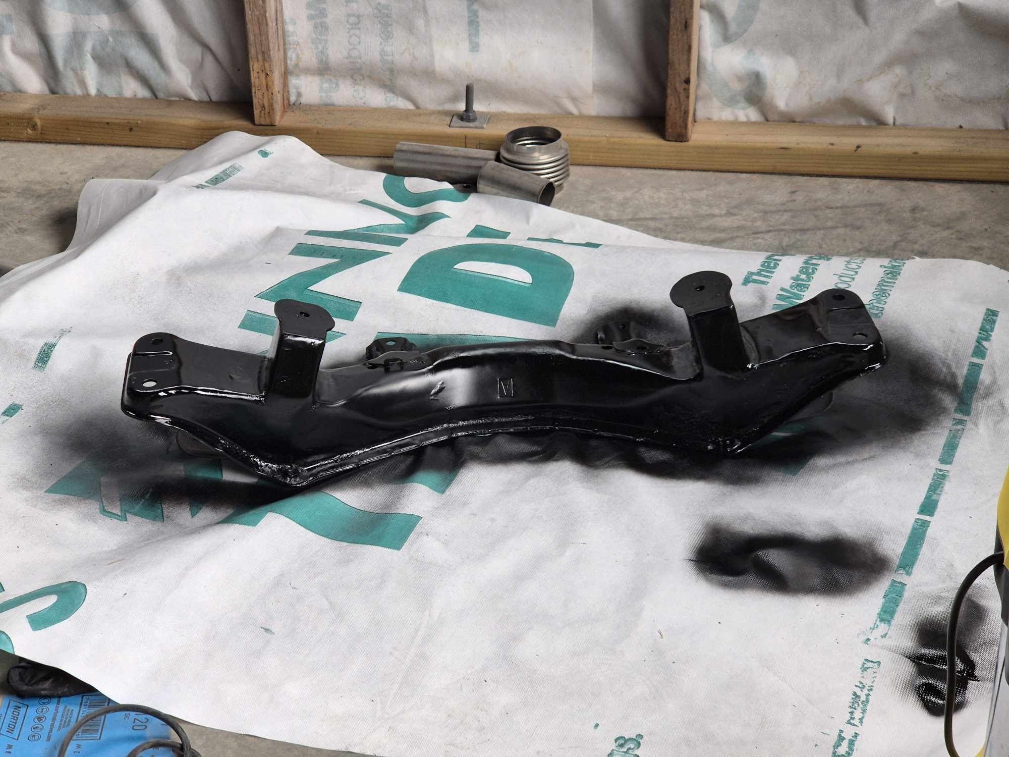
Well I'm making progress towards getting things going. Firewall isnt finished, or pretty, but if it stops my face catching fire for now, that's a win. Has got a severe case of myspace photo angles here, looks fairly rubbish in person. Posting here before it ends up on @cletus's wall of shame instagram story for being crappy things brought in for cert. Also welded up the engine mounts properly, and reshaped the front of the mounts so they look a bit nicer. Then a few coats of only the finest rattle can black. I'm out of town for work for most of next week, but I'm hoping to get the engine back in and fired up by next weekend.
- 131 replies
-
- 39
-
-
-
Third and most valuable option, is clearly drawing mspaint graphs for someones project
-
Ga3_zo and kp60nick's honda logo of head turning fun.
Roman replied to kp60nick's topic in Other Projects
Only just saw this thread... love it! Hope it makes it to OS drags, are these 4x100 wheels? -
Discuss here about Yoeddynz's little Imp project...
Roman replied to yoeddynz's topic in Project Discussion
Youre not wrong, the noise to power ratio of the A12 is incredible -
Almost as bad as saying a motor will do 10k rpm despite having no idea
-
1NZ has so much power, that the oil filter cant keep up with the car
-
Ahh so looks like where we are finally seeing the tipping point where he's pretty much rehashing same stuff and still without particularly convincing results. Pretty sooky to turn off commenting only about an hour after a video drops. Not sure why anyone is going to hire him as a consultant when he's not really proven any results yet. He's not going to have any credibility until he gets that V12 sounding good. Not constantly shifting goal posts onto other motors and setups. EDIT: Yep, hes dreaming haha. wtf
-
Ohhh this looks good hahaha
-
The c56 1nz bellhousing is 1nz specific, so theres no direct bolt on for a t50


.jpg.6788c72cbbf8d8b8d3ef7034010dbfd7.jpg)