Roman
-
Posts
7,218 -
Joined
-
Last visited
-
Days Won
39
Everything posted by Roman
-
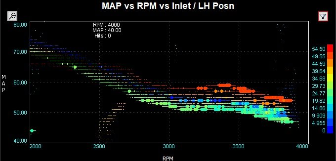
Okay I think looking at the data in megalog viewer gives some more sane results / actual labelled axes etc If we look at the cam timing angles which give the maximum vacuum then the results sanity check quite well against my full throttle cam timing. If you aim for minimum vacuum then it basically just says bang in 50 deg advance everywhere haha. So this is ramping up my cam advance much more aggressively than before but it's settling on around 20-30 degrees at 30% throttle which seems reasonable. It also sanity checks against the toyota documentation where it says "advance cam about half way" for medium load conditions. Will have to take it for some nangs though and see what its like now / maybe do same thing again at a few more throttle iterations. If this works well then I'll have a MAFless method for doing the same with quad throttles which is excellent news!

-
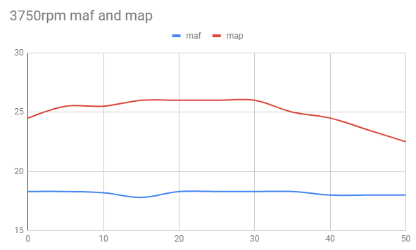
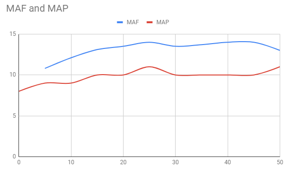
Doing the test again at 10% throttle was pretty painful haha. But some graphs from each rpm range. The horizontal scale is cam advance degrees and the vertical scale is map pressure drop from atmospheric (divided by 2) Conclusion: No idea to be honest. The MAF reading seems to be much more resilient to cam timing changes than expected. MAP is swinging around all over the show but it seems to cause very little resistance to fresh air coming in. Which maybe makes sense. I can say this though, once I got to around 40 degrees advance the car felt like it lost heaps of power.... Took a long time to get to 60kph in third haha. So perhaps that is the EGR effect at work. Probably needs heaps more ignition timing. Ultimately though this hasnt shown me anything as insightful as I was hoping and I'm not sure what the conclusion is here. Thanks for reading / sorry for pointless post / etc
-
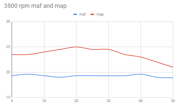
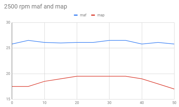
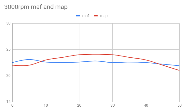
Yes so this is why part throttle stuff is so complex/interesting. As you say, what is the point of part throttle... You're obviously not trying to make max power or max airflow. So yes for me economy is the primary consideration, but also trying to get a good understanding of why things are beneficial while I've still got a good suite of sensors attached. As I want to come up with a good methodology for finding best cam angle when only MAP or TPS available as a reliable load axis. (ie quads) At the moment I can observe the effects and see why changes are beneficial but I honestly have no idea exactly why they are. Seeing the map signal change how it does in relation to MAF was an interesting thing. Sooooo I think I've found what I'm after. It only happens in the higher rpm of my test because 30% throttle doesnt pull enough vaccum to make it happen at lower rpm. But generally you see the MAF signal increase as the manifold pressure goes down because of increased VE. Buuutttt when intake manifold pressure gets low enough and there is enough overlap you start getting exhaust gas pulled back into the cylinder. When this happens map signal goes up and maf signal goes down. You can see here it only starts to happen right at 45+ degrees cam advance, the trend reverses: (Sorry havent labelled axes cos I'm a cretin but that's cam advance on horizontal and arbitrary rescaled numbers on the vertical) I think the 45 deg mark is the critical point where you start getting EGR effect happening. So thats whats relevant for economy, finding that point at each load/rpm combo. So I would expect if I run this test again at lower rpm with the same vacuum level I will start to see those converging lines start to happen at a much lower cam advance angle. As at half the rpm you have twice as long for a given amount of overlap to start pulling air back in from the exhaust. These tests even at 5500rpm are still at 75kpa give or take, so not much vacuum generated! Will try again later tonight and try get some ~2500ish rpm results at maybe 40-50kpa hopefully. I think when I swap to a dual VVTI engine and can adjust the exhaust side too. You will be able to make convergence happen sooner without the VE increase that comes from advancing intake cam. So can set the intake cam angle for worst VE / best pumping losses and exhaust cam for best EGR effect. I hope it works out as clearly as it seems it might!
-
Sooooooooo my favourite mystery topic. Part throttle Variable cam tuning. I did some tests tonight to try find out what cam angle might be "best" at a given throttle angle. By best I mean max airflow as read by the MAF. I used E-throttle to limit throttle angle to 30% max and did some pulls through the rev range, logging the MAF and MAP values as I increment through the intake cam angles in 5 degree steps. As expected, both the MAF and MAP values change as you advance the cam. But what was interesting is that there is loosely a correlation between achieving the strongest vacuum, and highest MAF reading. At 4000rpm with 0 degrees cam advance we are losing 11kpa and have 0.406 grams per cyl. At 45 degrees advance we are losing 16kpa and have 0.488 grams per cylinder of airflow. So 45% more vaccum and 20% more airflow. At 5000rpm with 0 degrees cam advance we are losing 20kpa and have 0.416 grams per cylinder. With 35 degrees cam advance we are losing 24kpa and have 0.456 grams per cylinder. 20% more vacuum and 9% more air. So whats interesting about this is you dont always have a MAF available for cam angle tuning but it loosely correlates to MAP. As a general rule from my testing it seems if you can get 10% more vacuum you'll get 5% more airflow. Similar to ignition timing though it looks like it ramps up quickly to best values then plateaus over a cam timing spread. I'll post something better later on once I've had a chance at figuring out how to format this mess of data. But seems like there's a fairly clear correlation which makes sense, if you are improving VE via cam timing then you are increasing the air demand... which the throttle restricts hence extra vacuum. I'll do some more tests at lower throttle with higher vacuum too and see if I'm getting similar results. Something else thats really interesting is that the best cam angle settings even at this low throttle angle are much higher than I would have expected. Based on absolutely no evidence I've just been slowly ramping the timing down towards zero throttle. It looks like past maybe 10-15% throttle it's just going to be the cam in a position very close to WOT for max airflow. It will be interesting to see if we see the same trends with much stronger vacuum. Will do some more tests through the week!
-
What an awesome run that motor has had! RIP in peace old chap
-
Some of you guys are being a bit harsh. His AE101 FXGT looks pretty good I reckon
-
Part of what's good about having a PCV system with 2 lines is that it works two different ways. When you are at full throttle, it blows the crank case fumes out into the line without the PCV valve ahead of the intake. Which then gets sucked back into the intake and combusted. Then when you are at low throttle the PCV valve sucks fumes into the intake with the intake vacuum, which then pulls fresh air the other way through the crank case via the 2nd hose so you are getting active circulation. (assuming it's drawing more air through the valve than your pistons blowby... ha) If you just dump both lines into a catch can then the only air that circulates through your crank case is combustion gas leaking past piston rings. How much difference this makes in the short term is probably sweet F all. Maybe just need more regular oil changes or something. Dont know. But its worth considering why there are two lines there in the first place before removing them. As Cletus has mentioned though, dont underestimate how much it sucks having a stinky fumey car. Wears thin pretty quick.
-
Paint 3D dont you dare utter those words around here Blasphemy! I'm still a bit mad about the anti aliasing they've added TBH
-
Oh thank you! I was looking for those pictures but couldnt find them. I'm sure that from memory they were around the 250hp mark when restricted to 10:1 which is pretty sweet in itself. But they could very well be higher HP especially if higher compression or had a tickle up since leaving the race series (which was friggen ages ago)
-
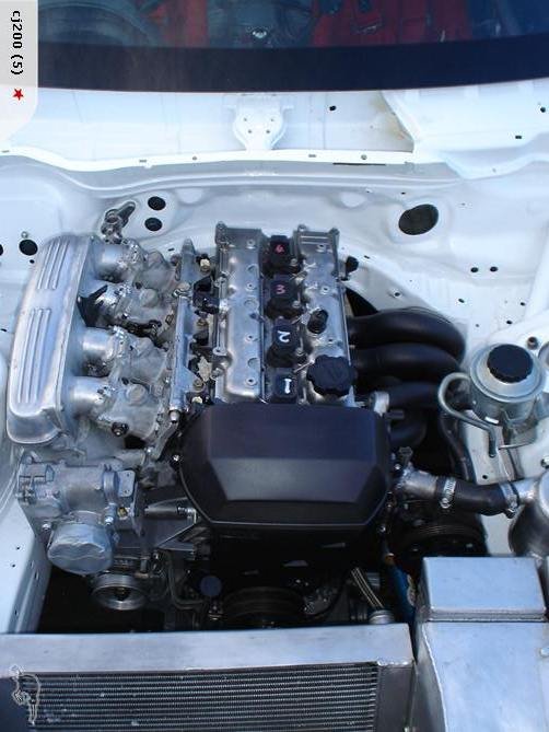
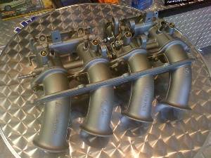
Some more sharns without finishing anything. Possibly some repeats sorry. But here's a pic of the Altezza touring cars that did really well in NZ many moons ago: Notice the ITBs fitted to factory runners. Or I guess you could say, factory plenum fitted to ITBs. These had class limited 10:1 compression, no VVTI (Banned?), big cams, and ITBs welded/mounted into the factory plenum. They made around 250hp with this config. Not sure if it was just class mandated that they had to stick to the original plenum/intake, or if there were other reasons for this setup. I managed to track down one of the guys that helped make these and he had some yarns to share: Interesting that use of the standard plenum wasnt just because it was mandated. Although maybe that's why the factory throttle body is still in place. Race car rules can be weird haha.
- 165 replies
-
- 14
-

-

-
Love how clean it looks with those throttles! 20V stuff is so messy looking.
-

Stu's 4agte 85 EP71 Starlet and 4age 84 AE86 Levin
Roman replied to Stu's topic in Project Discussion
This is bloody excellent. -
Printed moulds are legit! User error/inexperience not bad tools. One of my previous ones (rear one) formed the bell shape just fine. I tried something different and it didnt work. So now I know what else to try instead. Even as per below it's just being bit of a fuss pot to get that full return on it.
-
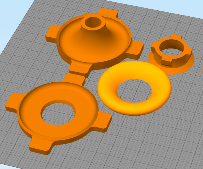
So that was a win and a fail. It was a win because getting the moulds polished up from 360 grit up to 2000 made for a nice result and the moulds popped apart super easy and definitely reusable without any damage inflicted to separate them. It was a lose though because my design didnt work too well. Trying to fold the carbon fiber up around the radius of the bell didnt really work, this is where the sheet needs to kinda do some pleats to make the turn. So its hard to hold it all in place while trying to push the top down, which due to tight tolerances would then just want to squish it all back out the sides anyway. So I think I need something else which pushes in from the sides instead of just down from the top. So maybe split into 120 degree segments or something. Aaaaahhhhhhhh frustrating but learned something from it. Also with some further consideration I need to remake them a smaller size anyway. This is why I'm glad 3D printing exists, it would suck a whole lot more to make these moulds any other way then have to restart a bunch of times!
-
bonkas tired old Lancer EX - Engine Swap/Build Thread
Roman replied to bonkas's topic in Project Discussion
+1 to that After all this effort please dont cook the head gasket or whatever, for sake of a water line! -
Discuss here about Yoeddynz's little Imp project...
Roman replied to yoeddynz's topic in Project Discussion
Just had another geez through your thread, that section with all the mspaint pics was absolute gold. Love it. Car's coming along awesomely too! New paint looks great. -
I really like what you're doing with the new engine. But I think you may have gone a bit far with lightening the crank
-
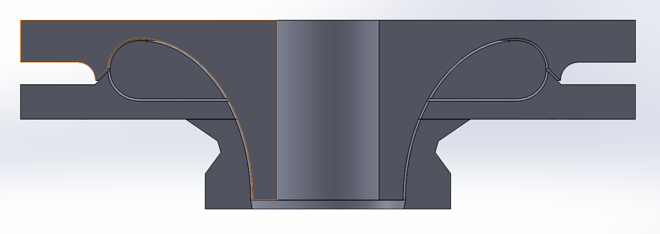
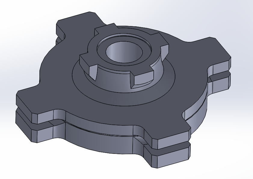
Starting on a new mould for some 4AGE ITB trumpets but learning from some previous mistakes. Problems from the past are that I've had too little draft angle on some parts that are quite long. Also that some of the excess untrimmed parts end up folding over something and locking the part in place. Also trying to use only 2 pieces when theres no reason not to use more if it makes life easier. Annndddd I think it will be a good idea to add some tabs so I can twist the halves relative to each other to try get the part free. Previously I've damaged the moulds by needing to smash a screwdriver in (or whatever) to get the halves apart. Hopefully this will help! I'm hoping I can make at least four, or even eight from the one set of moulds. I'll also try drill some little holes in the moulds, fill them with wax and then so afterwards I can use some compressed air to blow the halves apart hopefully if they are stuck. The center part of the bell shape still needs to be dissolved out, but cant think how else to get that sweet sweet return angle on it. Worth it... Fingers crossed! Fingers crossed!
-
I've modelled some different bell shapes before, and compared to ideal they all get Vena Contracta a whole bunch more and reduced flow. But the flow rate at which it happens to a large degree needs to be very high. They way I figure it, if a cylinder is 500cc then an intake runner just needs to provide 500cc of air before the valves shut, then it has the whole rest of the cycle to "recharge" So a poor shape is probably less of an impact than if it was steady state flow like on front of a turbine or something. To be honest I have no idea if this will be any better or worse but that's the fun Thankfully in this case the numbers for fuel to reach AFR doesnt leave much to interpretation so its easy to compare. Especially if peaks and troughs move around. The idea is to have enough combos ready to try out that I can put together quickly for a dyno session to do some comparisons.
-
Thats some sweet power, love the airbox setup! Do you know how long your total intake length is, down to the valves? Also interesting that with an engine with totally different (everything) it still comes on power at around ~5300rpm.
-
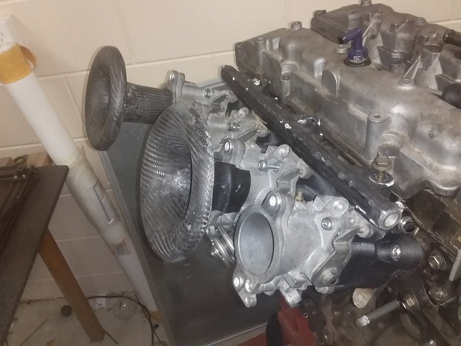
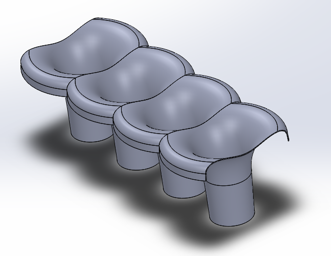
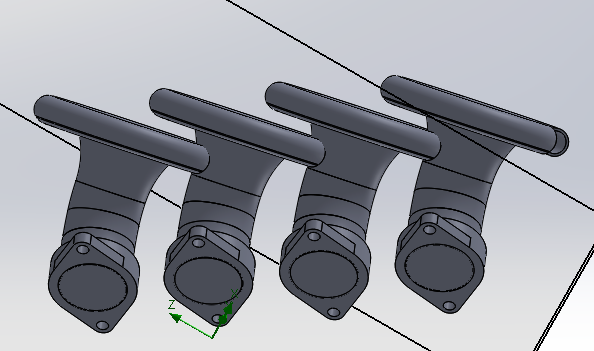
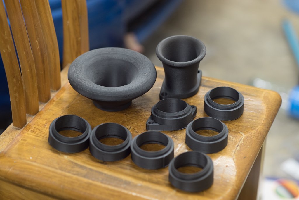
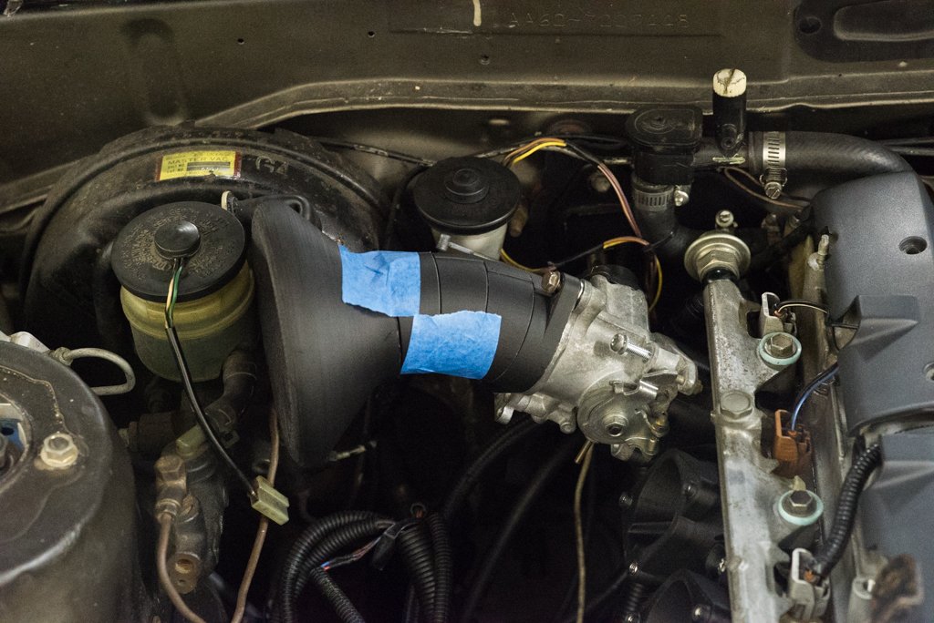
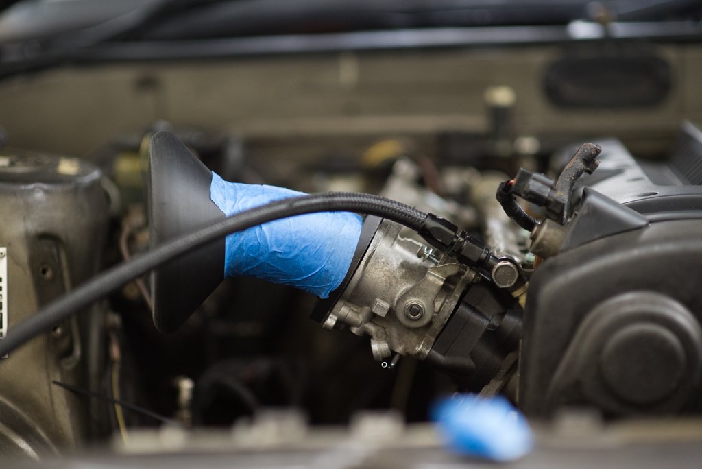
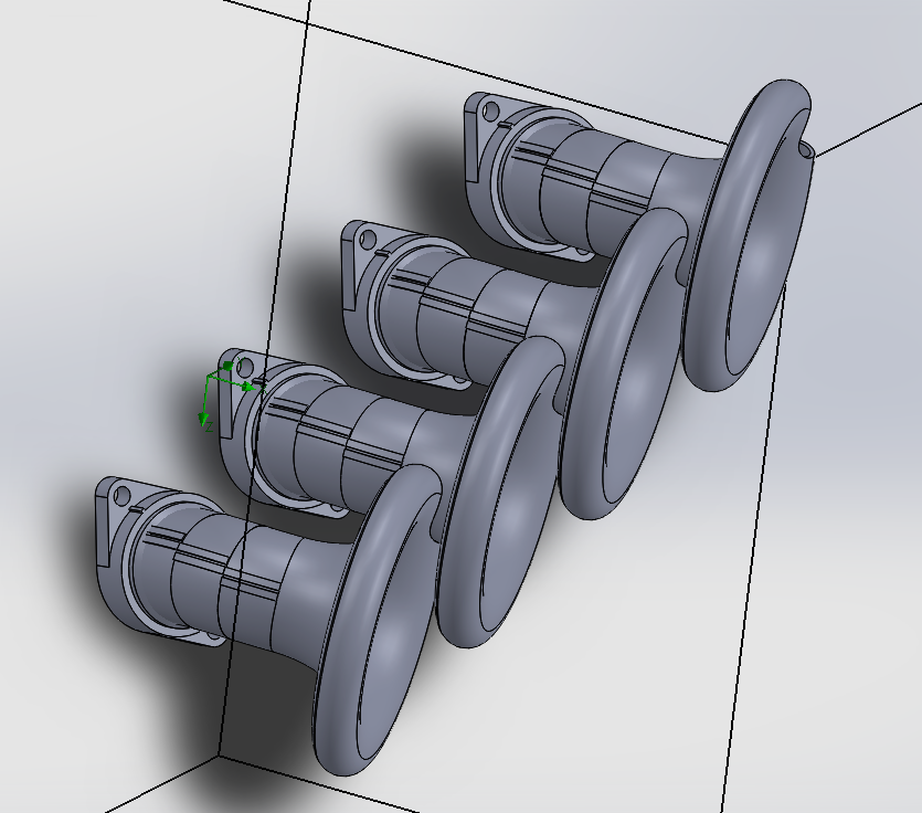
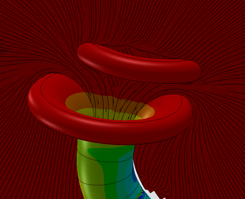
Soooooo for a while now I've had an obsession with getting a "proper" bellmouth geometry on something. I successfully made a big one for the big single throttle but I really need a different radiator arrangement to make it work so its been on the back burner. But the geometry to give completely straight flow is massively massive compared to what is usually used, so its a problem when you have 4x throttles close together. With the space that is available, you have to trim down the sides of each trumpet by this much to fit 4 alongside each other. (Obviously dont need to trim front or rear but lazy modelling) So it looks like you lose most of the useful area of the bell... And looks like it would be prone to "stealing" air and maybe fuel from adjacent cylinders? Not so good. Probably better just having a smaller radius on each. Either way, I printed out a full sized bellmouth (without trimmed sides) so I can size it up in the engine bay. As it turns out that thanks to having a brake booster I've got zero room for a trumpet this big anyway on the rear and hitting the bonnet on the front will be a problem too. I've seen those cool kits where people have all of those parts you can clip together to help build an exhaust manifold. So I thought I'd try the same thing here but for an intake. So printed some parts so I can try some combos for a single runner. Base piece, a bell, 3 x straight 20mm sections and 3 x 10 degree sections. Also pictured is the bellmouth provided with the ITB kit, for an indication on how rediculous the bigger one is haha. Unlike those fancy exhaust kits though mine doesnt actually clip together because aint nobody got time for that. Also, turns out printing the straight ones was a waste of time as there's not even enough room for just the bends. Neither front or rear really fits. pooz. So I'm reprinting the bend parts with 15 degrees per segment and a bit tighter radius to see how much that helps. Based on what looks like will fit though, tipping the trumpets slightly towards the front of the engine bay is actually pretty cool because it allows more useful bellmouth area per runner. A lot more! Most of the air comes from around the sides rather than straight ahead so will be interesting to see how this goes. The question is, is the efficiency gain of the big bell worth the efficiency loss from the bend. And is the bend worth the extra runner length gained. And does any of this make a difference when you're trying to wheeze through a 45mm throttle. And the biggest question of all, will I actually finish making any of this? Some preliminary nerding seems to look like the bellmouth partially shrouding the entrance shouldnt be an issue so long as there's a bit of gap. The colour scale on this, red is 101.3kpa and green is 101.0kpa so pretty minimal loss hopefully EDIT: Just found what the factory BMW S14 engine runners look like, makes me feel like I might be on the right track. Even if the big bellmouth isnt necessary, perhaps there is a real life benefit to having them staggered to allow more clear air around each runner than you can get with straight pipes that are butted up to each other.
- 165 replies
-
- 23
-
-
Great stuff! Now the fun part begins
-
Hahahaha looking at some sweet sweet waveforms while driving. The dream
-
Yeah partly because this adaptor retains the first part of the intake manifold. So its ports > ali manifold > adapter > throttles > trumpet Which isnt a bad thing as that first part of the manifold handles the transition from circular shape to the port shape and does a nice job of it by the looks.
-
Current manifold lengths as follows: Valves to end of adapter: 205mm Throttle body height: 74mm Trumpet length: 83mm Giving a total current length from valve to bellmouth of 362mm Which is surprising! A lot longer than I expected. The standard intake manifold is approx 40-50mm longer than this (with a bend) Can easily go another ~70mm longer if I put about a 30 deg bend in the runners to avoid the bonnet. So will give this a hoon.