Roman
-
Posts
7,233 -
Joined
-
Last visited
-
Days Won
39
Everything posted by Roman
-
Man this thing sounded awesome! So cool to see it back after a long break from drags, and 13.2 / 105.5mph in those conditions is friggen flying. Well done.
-
Yeah I dont think the motor is tired. The fact it ran consistently higher MPH over the line is a sign that its making more power than ever! It was just track conditions - we were basically scrambling to get some racing in, in between showers. All of the lost time was from my 60ft. If you get the racing crew to prep the track (spraying down VHT stuff to make it grippy) then it doubles the price of hiring meremere. And it doesnt benefit cars on street tyres so much, so it's not something suitable for oldschool days. Also I think it would be a waste of money to do that if the weather forecast is thunderstorms anyway haha. It was super awesome that we got to do some racing yesterday. The slipperyness of the track and that it was unprepped really cements the fact that for @cletus to have run a high 11 on a day like this, and @kpr running a 13.2 with a so-so 60ft on shitty tyres. These guys will be absolutely FLYING on a prepped track in ideal conditions. Cletus if you ever go to a comp meet or something please let me know, I'd love to come watch! I'll come take some videos for you, to make up for my noise pollution Edit: Photo from Philip, cheers!
-
After so many hardships etc with this car, to come to your first OS drag day and take out DYO was just bloody fantastic. When following the car to the pub it looked soooooo good on those wheels! Love it. A++
-
Nah you've got it all wrong. Making big black dildos is my main profession, it's where I got the idea from Yeah, so drags! Mega fun day, got heaps of runs in. Bit slippery on the track so no new best time. Quickest was a 13.6 and 100mph, 2.2 60ft. The rear bumpstop spacers, I think that worked well. However in the morning I also adjusted my front rebound to be stiff too, and this was yuck. Lots of wheel hop etc. Set it back to soft, and it was great. For the last few events with standard exhaust I was averaging mid-high 99mph runs. Now I was consistently crossing the line at high 100mph. Best of the day was 100.99mph. Stoked with that! I could previously launch at 7500-8000rpm, my PB was set with a 7500rpm launch. But this time I needed to launch around 5500rpm as the grip wasnt quite there. So on a good day at track with prep, there's easily a new PB once the 60ft gets in order. Might try get back to something in January. I made it to the fourth round of DYO despite some comical fuck ups, congrats to @Sungai Sungai for making Team 4AGE proud by winning DYO! Bloody good!
-
@kpr I think the numbers on your otherwise magnificent MSpaint diagram are the wrong way around... So 450 BTDC end of injection means its happening earlier in the cycle not later

-
Yeah it's not worth it for those. $330 for a PickaPart motor where you have no idea on KMs, or if the motor is even alive... and you have to bust your arse for a day to remove it. When it's sub $500 for a wrecker motor with low km and a warranty (that I instantly void...) However if any more NCP13s come through I'll spent the time to go get the box out every time haha. Holy shit a brick there's not many sleeps left till drag day. Legitimately more exciting than Christmas. Hopefully the weather holds up!
-
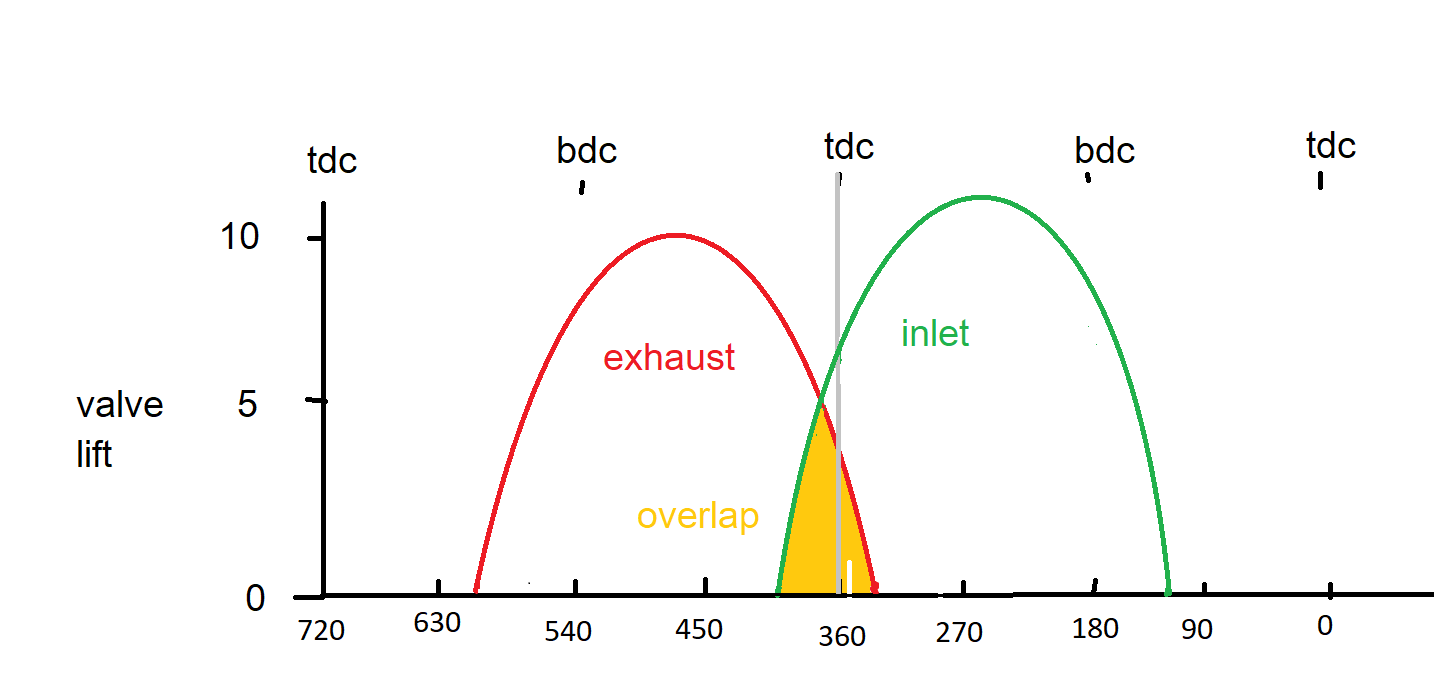
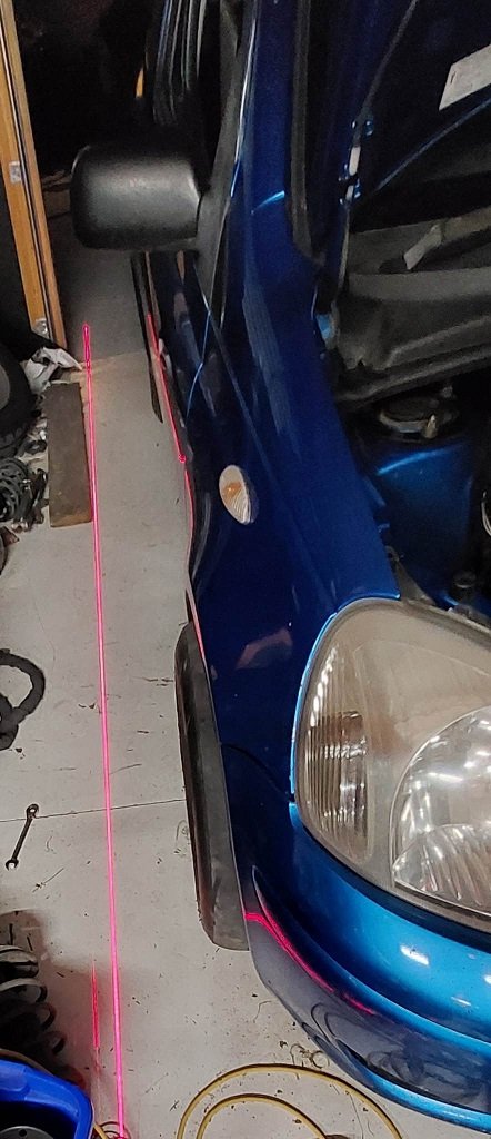
Previously when I've been to the drags I've had a play with tyre pressures and thats about it. 60ft time should be able to get down to under 2.0, but maybe only with a prepped track. But I reckon 60ft time improvements from mechanical changes will be possible too. The last time I ran, which went a little slower than best. I think I had lowered the car a little bit but not reset the alignment. So it was pretty darty off the line. So I have a few tricks to try this time. Firstly, lowered it all as far as it'll go front and back. Then I zeroed out the front camber just using a big steel set square thing. So the tyres look a bit mexican this way, but they nearly tucked under last time so must have been a few degrees of camber. Then thought I'd try set the toe as well. Sometimes you need to work with the equipment you've got, and sometimes the equipment you've got is some motherfucking LAZERZ This was a bit fiddly but worked well enough eventually. Got the wheels parallel then added a tiny squeak of toe out. Previous times I also forgotten to adjust the rebound settings on the front shocks, (usually set about half way) so I'll set these to as stiff as they will go as well. Then for the rear, I have made some bump stop spacers which essentially means ride height is sitting on the bump stops. So when it launches the rear stays where it is (hopefully) They are printed solid from the nylon carbon fibre stuff, but I'm going to wrap them in carbon fibre to make sure they dont explode. Hopefully that helps the 60ft time a bit. It's really easy to get the rear shocks out, so will fit these after arriving rather than having to drive there like this. In summary, super excited for drag day! Will be fun to see if these things help (or not) Gonna be good.
-
True good point! Didnt think about overlap.
-
Well I think all of the fuel still ends up going in. But it's probably more a case of combustion quality, as in, how well it's mixed with the air. If you manage to generate a more homogenous air/fuel mix by whatever means. Then it will report richer on the oxygen sensor because there arent leaner areas in the combustion chamber contributing to the average. What I found interesting from his testing was that going to 450 deg injector timing was beneficial at higher rpm. I always thought you'd end up reducing that number for higher rpm.
-
Dont worry, it will be full send at the drags. At a track day there's not quite so much benefit from revving it right out. But at the drags, its mandatory. I've got a few extra tricks up my sleeve this time, but it'll mostly be the weather gods I need to pray to!
-
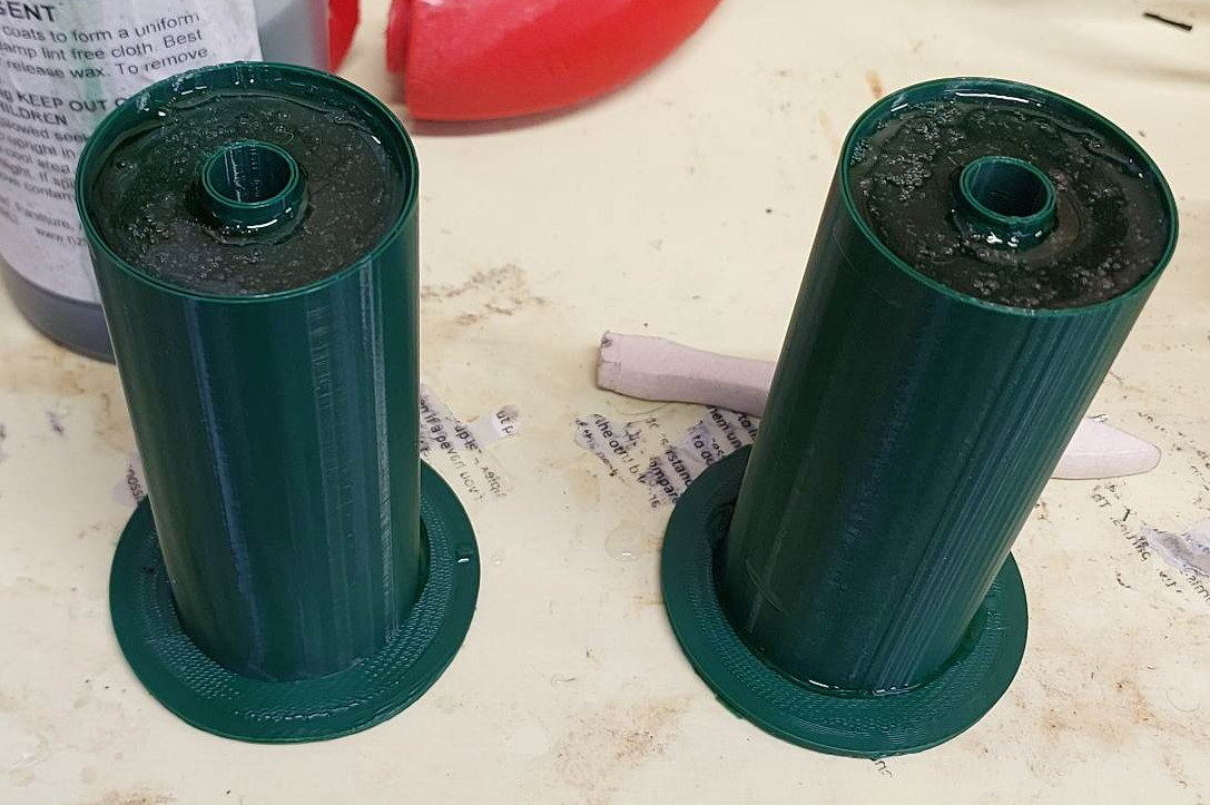
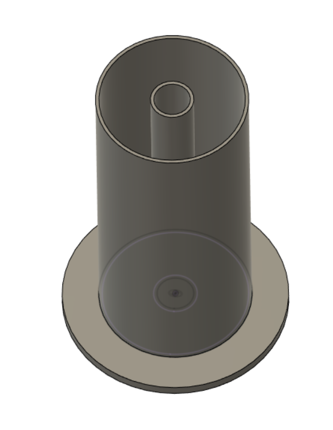
It's printed thin so that I can just break the mould off the outside. (and inside, hopefully...) Now have to wait 48 hours to play the "will the damn thing actually come out" roulette. By which stage, I'll have probably thrown these in the bin and the ones I ordered will have turned up haha. Bloody good fun making a mess though.
-
Ahhh crap was that the wrong pic? Buttplug_with_hole_for_beetles_to_crawl_into.jpg
-
Hah! My partner has a mini, and she's been wanting to put a more modern motor in it. I've told her 1NZ is a good idea and thats why I'm hoarding parts. Nice to know it looks to be actually doable.
-
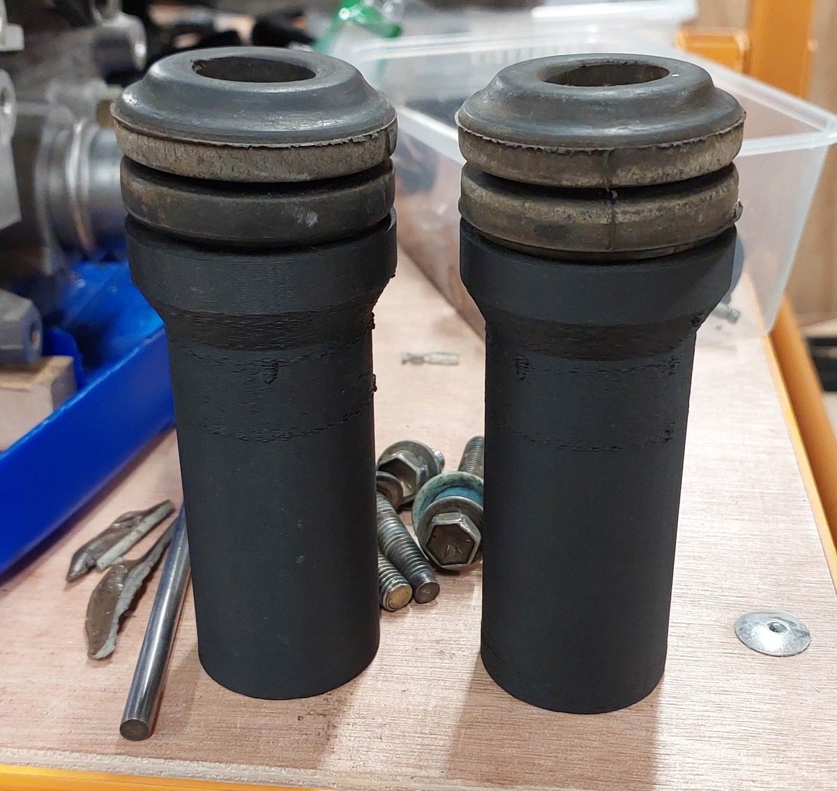
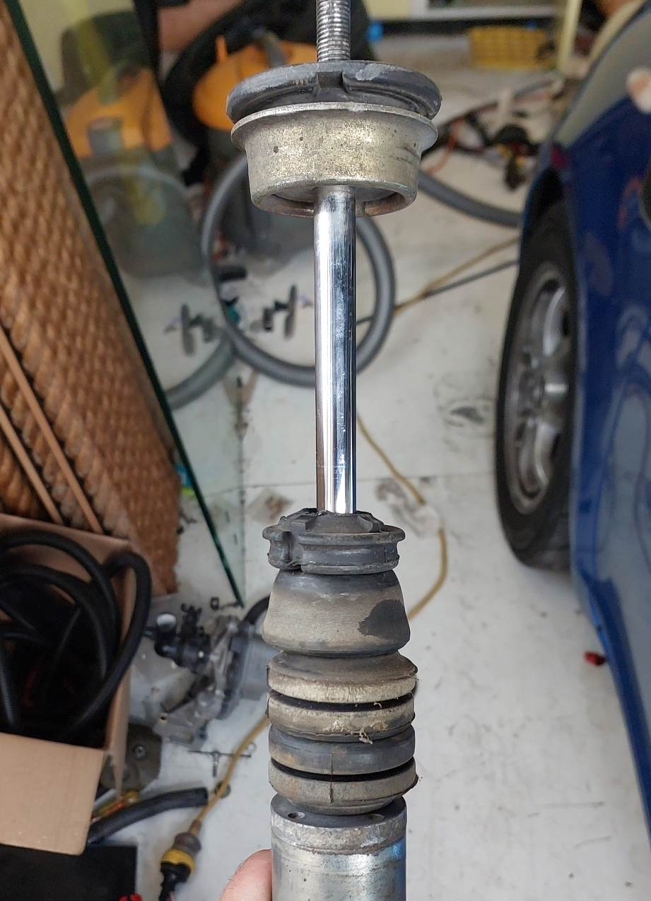
On the front, I am using Ohlin coilovers which have an inverted strut, which is some sort of wizard magic thing that I'm definitely not going to try open haha. Not an insert. I'm not sure if this means the bump stop is actually internal down in the guts of it? I dont think there's a bump stop on them otherwise, anyway. The front is not a problem. On the rear, the spring is separate from the shock. So the bump stop just slides over the shock body. So I can pull the shock in and out really easily. So it's not a drama to experiment with it a bit.
-
Yeah Maybe @cletus idea of a solid spacer with a shorter bump stop is a better plan than what I'm thinking. This way can have a cone shape or whatever be more effective. I'm trying Shore A 60 simply because that's what I bought a while back to fill my engine mounts. Might be a little on the soft side for a bump stop. Also it might be a disaster and impossible to get out of the mould. haha. The ones I've ordered are this sort of shape, 85mm long uncompressed. So probably compress down to smaller than I'd like.
-
I think it will be okay. The bottom casing is quite shallow to the crank, then one half of it falls away to a fairly steep oil pan with some baffle type things in it. So at least half of the oil falls directly into that, rather than having to go down the slope. The main oiling issue is likely when a rod punts my oil filter housing off the block I've ground the guard completely flush so that there's nothing sharp for the tyre to catch on. But still it just wanted to sit the body on the tyre. Just further down now. I'm not sure what sort of antics they were allowing for with this HKS suspension but it's pretty crazy how low it can go haha. To get the car to sit on the bump stops while having tyre clearance, has needed this many bump stops random bump stops buts that I found in the shed: Which is about 90mm with a little extra allowance for further compression. So I found on trademe some 85mm bump stops for 4x4 so hopefully they're reasonably stiff. I'm also going to have a go at casting some bump stops from polyurethane with a 3d printed mould. As I figure it might just be fun to do, then makes it easy to try some variations later on if it works well. So I'm just printing a very thin walled tube. So then I'll use lots of mould release wax on it, then after pouring hopefully I'll be able to just break it off.
-
On the toyota running speeduino. With the factory loom the earth for the cam and crank triggers tied together and ran to the ecu as a single wire. The only way to get vvti / cam angle sensor to read correctly was running a new wire all the way from crank trigger to the ecu. As I think the filter for interference or whatever on the speeduino wasnt great.
-
Super fizz mode about drags coming up! But I've also making plans to get to another trackday on the slicks. So I've taken the rear springs out to check for clearance. Looks sweet with no springs haha. I've chopped a bunch of the folded over part of the inside lip out of the rear guard. It should all fit inside the standard guard shape without rolling them out, or flares, or other stuff that would detract from the Je ne sais quoi of this magnificent beast. On the front, when sitting on bumpstops its got good clearance all round, thanks to the camber bolts. Sweet! (Front slicks not fitted in this pic obviously) So the only other task needed before a trackday (apart from avoiding blowing up the motor) is fit a bigger radiator.
-
That colour is amazing! Going to look awesome
-
I know someone that got Toyota VVTI working with a Speeduino. It could be that the PID settings are a bit whack? Not sure if you've seen this video before, but it's my go-to when I forget (often) how PID works! Brilliant vid.
-
Haha, that difference in dyno plots is wild! Cant wait to see how this goes
-
Holy shit! hahaha. Unreal
-
Yeah autotune can work great if it's got good filters for steady state. But usually doesnt exclude enough stuff. Or sometimes makes massive waves in the fuel table as it fluctuates half way between two cells, and keeps making one richer and one leaner to try get target.
-
Look forward to seeing some progress on it.
-
Sorry to hear things have gone so badly. As much as I do enjoy reading your well documented and reasonably light hearted masochism. Every man has his limits. I felt like I sold my SW20 under similar levels of being worn down by problems. Sucks. When this sells, what's next priority on your list of projects?