
yoeddynz
-
Posts
19,520 -
Joined
-
Last visited
-
Days Won
159
Content Type
Forums
Downloads
Events
Gallery
Everything posted by yoeddynz
-

Zac's rotary redux project, because he has too much spare time.
yoeddynz replied to ProZac's topic in Other Projects
Cough cough @ProZac don't be shy -
Yoeddynzs 1965 Hillman Imp. Dashing about with cowskin.
yoeddynz replied to yoeddynz's topic in Projects and Build Ups
So last time I popped by I was talking about my ring piece. I machined it to suit the location around the rear main seal holder, then cut out another ring piece from the engineering plastic. Harder to cut with the jigsaw than I expected. Put it in the lathe, machined it to the same size as the alloy ring. Machines really nicely. Makes lots of fine mess, much like a very not so tasty candy floss. I then drilled and tapped the alloy ring concentric to the main seal holder on the bell housing backplate. Then drilled the plastic ring, spot facing the holes and bolted it to the alloy ring. I now had an easily replaceable large thrust bearing. Next was the tricky bit. The crank has about .007" lineal movement on the crank. I wanted to set the thickness of the ring just so there's a smidge less because it will bed in. First I had to get close enough I could start accurately measuring it but I couldn't get in between the backplate and the flywheel to measure in any accurate way. So I used some plastigauge between the flywheel and its hub. Id fit it in place carefully and because the plastic was slightly too thick the plastigauge would show me how much I needed to remove from the thrust face before there was no lineal movement at all when the flywheel bolts were cinched up. Once I was at that point I could take a skim off the plastic and I ended up with about 5-6 thou movement. Perfect. Because its an English car, irrespective of what engine is fitted it'll no doubt leak. So in order to help it drip oil properly I added a tiny drain hole below the rear main seal.. ...and a hole in the bottom of the bellhousing. Always horrible having a build up of oil in a bellhousing, flicking all over the clutch etc. Now it can leak gracefully onto a drip tray I put the dust sheet over the block and pulled the cylinder heads out from under the bench. Gave them both a clean as best I could with the valves in place. A nice job to relax into in the afternoon sun... Heads much cleaner I put one aside and set up shop on the bench to remove the valves and clean them up. I was going to put the bits in an egg tray but it wasn't really ideal so instead a plastic tray with moveable partitions. Very careful not to mix any bits.. The seats and valves were all really good. A bit of carbon build up behind the heads on the exhaust valves but they all cleaned up mint in the lathe with a wire brush. The stems had barely any sign of wear and were jiggle free in the guides. More signs that this engine really is a low mileage, well maintained unit. I made a basic wooden jig to hold the heads at the valve angle so making for an easy time to accurately lap the valve seats clean. They came up sweet with minimal lapping. Happy that the valves and seats were good I decided to give the ports a little clean up. Nothing too flash but there's a few casting ridges etc that I could remove... I was going to use the air grinder but the Dremel seemed a lot more suitable, especially when I remembered I had the flexible extension I've never used before. Wow!! Its perfect for the job. Just a tickle.. Into the sunshine and swapped over to some tiny sanding drums to smooth things up. I wanted a nice clean but 'rough' finish on the inlet ports. Certainly not polished. The exhaust ports were smoothed off a lot more but not polished either, a waste of time for very minimal gains on one of these mildly tuned engines I think. If this engine swap works out well, without grenading the transmission etc then another set of heads will be a fun thing to play with. More on this later.. once the port clean up was completed I fastidiously cleaned the heads and blew away any signs of anything that might cause harm if it were to get into a bearing surface. Brake cleaner and the airline was perfect for this. Next I sealed up the ports and fitted the plugs back in place.. Brand new stem seals, the ones I'd ordered from Norway of all places and they had taken bloody ages to get here, but here they are.. Refitted the valves and called it done. Rise and repeat for the other head. Then I had two nice clean heads ready for service.. Next job was the cam follower assemblies. Again, like the heads, not too dirty, no real signs of oil staining etc but certainly in need of a clean anyway. The underside showing the rockers.. Plastic tray compartments cleaned and shuffled about to suit their new role. One assembly at a time. The rockers, followers and rocker shafts show next to no wear. The lack of needle roller bearings between the rocker and the eccentric lash adjuster cam thing dates this engine to something around early 90s. If I'm correct I think they added needle bearings around 1993. Here's a pic to show how the hydraulic lash adjuster moves the cam and so take up the slack in the rocker.. These adjusters are like many you might find in car engines. To make things easier to explain here is an exceptionally accurate, highly detail and finely drawn technical drawing I just did on my phone... Oil is contained with the the unit and held under pressure by the engines oil system, fed to each adjuster by oilways within the cam follower cradle. The piston part, uppermost, is a very fine fit into the base and held in place by crimping. In order for them to work properly the air must be removed from the adjusters and that's what the spring loaded steel ball is for. Push that in (red arrow) and air is expelled. If they were to be left on their side or upside down the oil within will eventually drain out and air introduced. From what I can work out they don't self bled and the oil within is not constantly renewed. So over time the oil will break down and become dirty just from the minute amount of metal on metal wear within. Mine certainly showed as much as I cleaned them out and they took a good bit of working before they stopped showing any wisps of dirty oil. There is a special Honda tool that is used to push the ball valve in. I machined one up in aluminium with a bit of tig rod set in the middle but in use it wasn't as good as just using a neatly shaped bit of 1.6mm tig rod. Using this I was really able to see what was coming out each time I purged them after draining. As per the manuals I used kerosene. I had three little vessels filled. Then, after they had been left upside down to drain any residue left over I re-bled them using Penrite fully synthetic full zinc bike oil. I figure that since the oil in these adjusters might never get changed out it makes sense to have some decent oil with good anti wear additives... plus I happened to have a container of it because I use it in our Honda big red quad bike The adjusters were now all clean, lubed and showing no movement when pressed, which is what is required when bled. I then cleaned the rest of the parts and reassembled. I mounted them on the wall facing up - ready for when I need to fit them to the heads. Interestingly whilst doing some googling on these units I discovered that the Honda Valkyrie 1500, a sort of sportier cruiser version of the touring goldwings, has apparently got slightly hotter cams. I have not found any definitive info on exactly what the difference is. More lift or duration etc. But more interesting is that they also ditch the hydraulic lash adjusters and instead use simple screw and nut type adjusters on the rockers as per many other Honda bikes. See here... So my future plan if this engine setup works out ok would be to locate a pair of Valkyrie heads/cams/followers and have a play with them. At the same time I could setup these BMW itbs that hannah so kindly brought back from the UK ... They'll need the tabs lengthening so to space them apart a touch further to suit.. Other parts, this time delivered by the postman... Bosch style (but not price) Idle air control valve, various sensor plugs and some shiny new exhaust gasket rings and nuts. So the heads are ready to go back on but before I do I wanted to sort some other little jobs out while the engine is compact and easy to move on the bench. This morning I made this... It's designed to stop oil surging back up the filler tube. It really is probably not needed actually bu I see no harm it being there as a belt and braces add on. I'e still yet to decide on the final height and extension of the filler.. Oil height and volume is going to be more than sufficient I think. I'm not sure what the height was in the original configuration and I seem to have foolishly thrown away the original dipstick so I cant check that. Dipstick went in here.. I'd like to have the oil height maybe an inch below the crank throw. I'll have a think about this. Anyway - lots of room for oil. I think about 4 litres at least. I also need to add a vent to the crankcase. Most likely it will be here, right below where the little owl is sitting... Because there is a useful casting that would shield the vent hole from oil splash..- 121 replies
-
- 48
-

-

-
I might have a spare scooby starter you can have. Not sure what those earlier engines have fitted.
-
Engineering porn straight onto instagram that.
-
Yoeddynzs 1965 Hillman Imp. Dashing about with cowskin.
yoeddynz replied to yoeddynz's topic in Projects and Build Ups
The 'hard' part of assembly completed I can now chip away at the rest of the engine. I'm taking my time, enjoying the process and tinkering with bits as I go along. The next stage is the oil pump and filter and connecting tubes. First thing to go in was the oil filter pedestal. I looked at the hole for the oil pressure switch/gauge sender and it just didn't look deep enough. I'd tapped it out with the appropriate 1/8" bsp tap and it fitted one switch I had but It just didn't look right for my Imps sender. Only one way to double check. Out to the 'garage' where little imp is safe and dry.. I removed the sender (luckily very easy access on the Datsun engine) and tested it in the hole. Sure enough it only barely started on the thread. Out with the bsp taps and I ran one in a lot further. Much better... Tested it in place. Easy access. I wanted to sort this out now as I could make sure the oil ways were completely clear of any swarf etc. Having to tap this hole out in place after fitment would have been a risky thing. That done I sealed up the filter mounting side with tape and fitted the unit in place.. Oh but not before taking this pic after assembling all the parts together in one place... I also weighed the block with crank/pistons in place before the oil system went in too. More about weights soon. But back to the oily stuff. I bolted it all in and set up the chains and sprockets. Some of the tinkering I mentioned as things went together included milling out as much as possible from all the various plates and mounting blocks. No point in extra weight and anyway- the bits looked nicer for it. Not that anyone will see them. But I know they are there in all their lighter machined goodness. You can sort of spot some of my Jenny Craig weight loss efforts going on in this pic on the idler gear mount.. That lot in place I moved on to another little job. For oil changes I needed a sump plug. This neat little stainless item arrived from China.. M12 x 1.25 and I didn't think I had a tap to suit. Luckily I remembered about a set of Chinesium taps my neighbour had given me a few years ago. Probably made of cheese but hard enough to tap the required thread I needed. Look at the spelling on the box ... Drain plug sorted... Cylinder heads will be next on the agenda. Give them a clean, strip them down, check and softly lap in the valves etc etc. I'll also be stripping, cleaning and bleeding the hydraulic lash adjusters. For that job I wanted a tray for all the little bits. I popped over to the neighbours farm as she has many many many chickens. Got some egg trays. She also gave me some sponge cake because she knew Id have run out of the cakes Hannah had made me. I like cake. Another job I am mid way through is creating a 'thrust' ring to go between the flywheel and the back plate. It's really just a belt and braces fitment in case because why not. As shown in the last post, I feel that the stock Goldwing crank thrust bearings are fairly minimal. This ring I'm building will only come into effect if the Goldwing item gets worn to much. There's about .0006 ~0007" clearance on the crank. Good oil and not sitting at the lights with the clutch pushed in should help things last. But just in case I will add this. I cut some 8mm alloy plate into a circle and then machined a ring up... Ordered some special Tecast Pa6c oil impregnated engineering nylon which arrived yesterday. I also got a bit of bar which will be used later on in my gear linkage. See my lovely shiny ring... More on this next time. I mentioned weighing the block earlier. I thought it best to weigh all the engine parts (because curious and couldn't wait actually). The block with crank/pistons was 36kg on the pretty accurate bathroom scales. Everything else I weighed with the digital scales. I wrote stuff down and took a pic.. Pretty happy with that really. It includes the clutch assembly and the engine side of the engine mounts. When I first started stripping this engine down many moons ago I had always hoped I might see a final weight of around 80kg - but unrealistic when the block and heads are 56kg alone. I'll wiegh the Datsun engine when its out but google sources claim my A12 is 87 kg so I'm stoked with a circa 10kg increase there. The Subaru leone transmission is about 9kg heavier than the Imp item. The big benefit is that the flat six is shorter in length and majority of its weight is down low in line with the crank - not up high like my current Datsun is. I'm super happy with how the current car handles so this will be a decent improvement on that. Plus I get the rear parcel shelf back for shopping bags! Since I had an empty workshop for a bit I thought I'd reunite Impy one with impy two for a few nights. Maybe I'll get baby imps?- 121 replies
-
- 60
-
-
-
before you ever fit that 131 box to anything can you please do a spot of filing to the marking on the box...

-
SR2’s 1947 Vauxhall “Rigamortice” Discussion thread.
yoeddynz replied to sr2's topic in Project Discussion
"The part arrived in 4 days complete with 2 optional rubber boots. Great bunch of guys to deal with, great value for money, and their level of customer service put the NZ opposition to shame" This is often so bloody true and it pisses me off no end. Its not hard to be courteous on the phone, show a little interest and at least seem like you're trying. But so many places I ring here are fucking useless at these basics and are probably the first to grumble when they hear of folks buying elsewhere. Also- keep a customer happy even on the little sales, be polite and you'll get repeat customers and reccomendations. But this seems to fall on deaf ears too. Your gasket woes. Cant you just pull the old gasket out, clean the surfaces and fit a new one with a split at the top. A tiny dab of sealant on the join and it shouldn't leak? -
I dont know if this is a totally stupid idea or not but could you add a pulley between the driveshaft universal and your gearbox or axle and drive the AC pump from that. Obviously its only going to work when your moving but better then no AC at all?
-
Jb weld will fix the world.
-
Yoeddynzs 1965 Hillman Imp. Dashing about with cowskin.
yoeddynz replied to yoeddynz's topic in Projects and Build Ups
Oven cleaner. Just a tiny bit on a rag was perfect for removing the last stubborn bits of carbon staining on the pistons. Now for the what I fear is the trickiest part of the engine assembly which is assembling the two crankcase halves together, the last half over 3 pistons. Its the bit that's if not done correctly could at worse break a piston ring. Even the one of the manuals states this... So I started the process by giving the crank case halves a nice clean over and prep. Then I got the crank out from its hidy place under the table. Gave it a good clean and as per advice from @GregT double checked for any burrs in the oilway holes. They were spot on. Very nicely finished all over. Put the crank in the hole... Note the smallish crank thrust washers... (edit- this is just one of them - there's another on the flywheel side but I couldn't get a pic of that one because the flywheel adaptor hub is in the way) Rotation direction aside, this is probably the engines weakest spot in terms of being used as car engine, with a manual box that is. Good quality oil with snake oil ptfe treatments and don't sit at an intersection in gear with the clutch depressed etc etc will be the name of the game However all is not glum because after some extensive bedtime scheming and designing I have a good idea as an extra precaution I might do. Anyway- back to the build. Now I had to make some special Goldwing specific tools. Firstly are the piston ring compressors. Here's a pic of one of the Honda items ... Basic and gets the job done. But expensive, especially combined with the other bits and anyway - I like to make as much as I can. I got a bit drainpipe from a local plumpers supplies. It was actually a perfect fit over the piston. Like 10 thou smaller in ID and it wouldn't have gone on. Fluke. Lady couldn't be bothered to charge me anything either I chopped it into bits... To machine such flexy plastic rings I needed a support. Luckily I had a lump of thick alloy tube leftover from removing a customers lpg setup. I skimmed it down... Now I could turn a taper onto the rings and make lots of plastic mess... The taper locates the compressors into a tapered lead at the base of each cylinder liner on the LH case, so guiding the compressors and stopping the chance they might flex out as the case is lowered down over the pistons heads. I had to get the taper angle just right. Cut each rings in two. Now for some decent quality velcro. I found a meter pack of one side sticky, the other for sewing. Perfect! I then bolted the clean, shiny pistons in place. First to go in were the ones for the RH case that the crank is bolted into. Then the left hand pistons get bolted in place... More tools. This time some woodwork. I searched in my wood supplies and found a nice lump of Eucalyptus. Firstly two support blocks made to measure according to sizes specified in the manuals. They are used to space the cases at certain stages. Then a trickier bit which is used to hold the upper most piston straight and in the right location. In that last pic you will note two white plastic supports for the two lower pistons. Honda sell these as part of the kit. Not cheap either. So I cut up a bit of plastic chopping board to suit. The velcro strips needed wire pulls as like the Honda items. I have no fine wire, or a piano to steal some from. But I have a fishing rod, now with a shorter line. So it was all set up for the 'big lowering and clamshell manoeuvre' Oil the bores, the piston crowns, carefully lower lh case. The top compressor slid down the piston, rings were inside the bore and the case sat on the upturned blocks. Remove the wooden piston support and then slide compressor down and remove by pulling on the fishing line loops. Please excuse the lack of photos. I was a combination of being both nervous and satisfied and not thinking camera. Not until the block was over the next two remaining pistons and rings were in place. Then I took some pics... Plastic chopping board supports removed.. Final two compressors pulled out... Case faces cleaned one more time, dowels reinserted, 2 new O rings installed, lower surface gets a thin spread of 3 Bond sealant. Case is lowered then all these cleaned and pre-organised bolts go in and get torqued down. Job done. Phew !!! I had a cup of coffee and tidy up in preparation of the next stages. Its nice having a break from work and not having customers jobs cluttering up the space. Just a little spare Imp...- 121 replies
-
- 67
-
-
-
I used a ford mundano unit and had to machine a steel extension, larger diameter, that's just a push fit into the existing bearing face. Existing bearing was flat faced. Extension has a convex surface so the clutch fingers 'roll' as they go through the motion inwards.
-
Can you please mount a camera so we can all witness it.
-
I don't know if there's a drain fitting but good idea though, Oh for a little window with a level line on it just like so many japanese carbs
-
Re: float heights. It's a tricky one to work out exactly what the height should be, where to measure it etc because there's so much conflicting info out there for the dvg carbs as these. But I took the top off his carb (interestingly - it had a neat little spring loaded holder at the bottom of the choke rod, manual choke, so no tricky circlips for me) and chhecked the float height. Possibly a tad high but yeah, hard to confirm. Anyway - I lowered it by about 1 or 2 mm and reassembled it. The owner reckons its crisper, smells less and seems better but I've told him to give it a bit more time and we'll see how it goes.
-
Discuss here about Yoeddynz's little Imp project...
yoeddynz replied to yoeddynz's topic in Project Discussion
And it keeps the dust down -
Discuss here about Yoeddynz's little Imp project...
yoeddynz replied to yoeddynz's topic in Project Discussion
Well yes, of course you would do that, because on your cars it would drop straight through and end up on the ground anyway -
Discuss here about Yoeddynz's little Imp project...
yoeddynz replied to yoeddynz's topic in Project Discussion
Yeah the first lot of oil that goes through this engine will get dumped pretty quick, pretty much used as clean up purge and then I'll decide on what goes in next. Opinions on oil via forums I think even oldschool has an old oil thread somewhere. The grandmaster thread is possibly the one on some ferrari forum I once found. -
Discuss here about Yoeddynz's little Imp project...
yoeddynz replied to yoeddynz's topic in Project Discussion
Cheers Greg- I was certainly going to clean out the oilways on the crank so I'll now pay particular attention to any such issues you describe! I have yet to go down the forum rabbit holes on what oil these engines favour - especially as this wont have any transmission gears underslung to worry about. -
Yoeddynzs 1965 Hillman Imp. Dashing about with cowskin.
yoeddynz replied to yoeddynz's topic in Projects and Build Ups
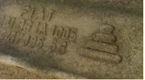
I went with curved. I thought I had a 16mm/5/8" tube bender but its actually a 1/2" so instead I heated the tube up and bent it carefully... Turned out OK. Not too ovalised or squished at the bend point.. Cut out a small section I needed and welded it in place. Then brazed the Nissan regulator flange on. I now have plenty of clearance around the spark plug hole and the regulator is tucked away a little more from obvious sight. The fuel hose will run neatly over the starter or possibly run it below. I'll decide this when its all being set up in the car. As you can see I had fitted the transmission in place and the starter so I could decide better on the positioning of things. That rail finished I moved onto the other side. I decided I'd run the hose down. Fitted the inlet bit in place, orientated the hose where I wanted and marked it. Brazed in place... Filed the joins and tidied things up as and where I saw fit.. My work area that morning.. Almost getting to the reassembly of this engine But before I stripped it down I marked out the perimeter of the engine crank case onto the rear plate/bellhousing combo. Then I very carefully, with a teeny little slot drill, milled some sealant retention grooves between the bolt holes to a level just above the expected oil line.. Now I could strip the engine. But before I took the crankcase halves apart I gave them a quick tickle with a wire wheel. I'll be painting them soon so I wanted a good smooth surface. It'll never be as smooth as a factory finish because the old paint is too chipped. But it'll look neat enough. Then finally back down to two halves... I pulled the pistons out from their storage spot for a clean. They are actually way cleaner than I remembered with really only the tops having light carbon build up. Interesting and pleasant surprise I discovered. The pistons have press fitted wrist pins. I had always been assuming they would be secured with circlips because I had been told this engine was an '88. In the first year of manufacturing of 1500s, 1988, they had circlips and then they changed to push fit (I'm hazarding a guess that they might have had some engine warranties due to adventurous circlips leaving their allotted slots? ) Anyway. That's nice. There is also one other minor change made to the engine internals around 1990ish, maybe a bit later, when they added needle roller bearings to the valve lash rockers. I'll show that in more detail when I get to it and will discover what type I have. Back to the pistons. I've set up a little cleaning station at the bench and have been getting high on acetone. Too much fumage really - I think will leave the rest until next time and do this job outside. But they are coming up pretty sweet! After they are cleaned up I'll have to make three special piston ring compressors for the assembly of the second crank case half over its 3 pistons. More about this next time- 121 replies
-
- 49
-
-
Imp vans are so fucking cool. That's all I have to contribute at this point. Yours, Jealous Alex.
-
It's just more my hesitancy buying stuff from folks who can't even communicate. Something goes wrong and it becomes a ballache. Still very curious about how his products can now perform at a level that he'd previously claimed another company was telling fibs when they did it. Curiouser and curiourser...
-
Alan in toronto
-
I've only ever killed one sensor, a 4.2, which was coupled to a Inovate mtxl. I think I know why though- thermal shock from having the ignition on for a while, the sensor heating up and then starting the engine is what I suspect killed it. Anyway- not going to touch their products again. I think with a newer controller from Aem or 14/7 I wont have these issues. I don't think I need to stump up the extra pingas for a adv sensor though. Not on a 100 bhp NA engine that's not really going to see silly revs/will be more of a road cruiser. Anyway - 14 point 7. Fuck me he seems a bit useless at communication. Doesn't fill me with confidence. I'm glad to hear he stands by his products because it does seem from other forum posts a fair few of them have issues. But then you'll always hear about the faults first. Reading the above forum thread is interesting too. I'd love to have seen him come to the party and just swap units with AEM fella so they can test each others rather than him just having a sulk. Interesting to see that his latest units now have a response time of 10-20ms depending on the sensor - a time he had been harping on was impossible and the AEM were manipulating their results Either way, whatever unit I end up with - be it an X series or a S3, it'll be streets ahead of the old Inovate mtxl/4.2 combo.
-
I'm still trying to decide on which wideband setup to get. Its either going to be a 14 point 7 spartan 3 or an AEM x series. Both offer CANbus for a nice clean accurate and fast signal that I might as well go for. Anyway in searching for info/tests/comparisons I found this old thread that spans a few years on freds diyefi forum. Its all about wideband controllers and gets quite nice and nerdy. Skip the first load of pages and head straight to page 16 which, in 2015, is just after AEM released their x series. Make some popcorn and read the entertaining cat fight between DelSolid who works for AEM in California and toalan, the Canadian behind 14 point 7. http://forum.diyefi.org/viewtopic.php?f=6&t=2267&start=150 I've not yet finished reading it all. But its getting heated
-
Yoeddynzs 1965 Hillman Imp. Dashing about with cowskin.
yoeddynz replied to yoeddynz's topic in Projects and Build Ups
These bits turned up thanks to @Corbie .. Sweet. I've got some coils and a spare ignitor. but hang on a minute... something ain't quite right. One of these things is not like the other... This will give me nightmares if I fit a mismatched coil. I'll have to look about for another matching FC0021 While is was looking at ignition stuff I dug out the original Goldwing coils and leads from the store room. Then this happened to them... The leads have molded rubber boots, shaped neatly to seal the spark plug holes. Three of them are perfect for the LH bank and will point the leads nicely towards the front of the car direction. At this point in time I am planning on mounting the coils up under the parcel shelf, sort of above the transmission and out of immediate view. But the other 3 boots left over are all over the place. Only one remotely points towards the transmission. The standard leads are solid copper strands and from what I know they are not the best thing to have around electronic engine management. Maybe they are OK? I'm not 100% sure yet but what I do know is that they were too short and a bit messy looking. At the spark plug end there's a very neat little brass fitting that screws into a plastic guide inside the boot. See the bits here... The tread is m10 x 1.25. How handy. I'll get a long bolt, screw it in place, clamp the bolt head firmly in the vice and simply pull the rubber boot off the plastic insert... Poos. I superglued it back together and put it out of sight. It'll be fine. I think I can pass 7mm silicone leads through the insert anyway when I make new leads. I don't like the way the silly boots that refuse to point the correct way bend awkwardly. This is the best of them. Not really neat enough and I only have the one of this shape anyway. So I got a sharp knife and performed a little circumcision on one of the 2 remaining... The end tapered nicely with a flapdisc on the grinder... And looks OK in place. If I get some nice flexible leads they'll curve the way I want fine I think. Now the fuel rail fittings. I had a certain look in mind, tidy, simple and pointing the hoses where I wanted them. I machined up these bits in stainless. You can see the first one I had made and brazed already just as a trial.. silver soldered them together. Not as neat as I wanted- possibly it doesn't flow so nicely on stainless? Luckily the worse bits face down. Now to get the angles just right and mark them.. Then braze them in place... I'll clean them up in the morning. My plan is to paint the rails in black epoxy and leave the stainless bits clear. Hopefully they'll be tidy enough for this to work out well. The rear inlet I have yet to decide on with regards the positioning of the hose. I'm leaning towards it heading down out of the way rather than across because I'd like to keep the area around the throttle body as clear as possible. For the fuel pressure regulator outlet end on the other rail I had to first turn the end of the reg mount down. Awkward in the 4 jaw so I mounted it to a lump of alloy that I'd turned a spigot onto, so centralising the mount. Regulator can now mount here... But it just annoys me a bit that its sitting there, right over a plug hole, on view. Luckily the home made spark plug wrench I'd made... ....because I didn't have one to suit the plugs/hole size on this engine when I was stripping it down, still fits and works but would be better with a smaller diameter shank.. But maybe I extend the rail with a bit of curved tube and mount the regulator sort of here... I shall ponder this and look at it tomorrow. Time to kick up my feet and do my next bit of google homework - look up leads for the ignition.- 121 replies
-
- 49
-
-


.jpg.b78ed7c174cc5c499060e6371a919ef5.jpg)