


Flash
-
Posts
1,717 -
Joined
-
Last visited
-
Days Won
2
Posts posted by Flash
-
-
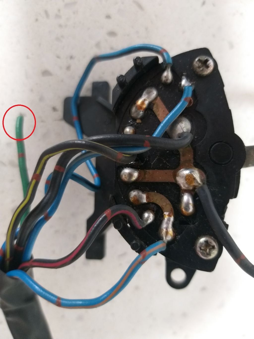
Looking closely at the loose wire its green with a red ring running around the wire every so often.
What has got me beat is that I definitely cut the other end of that green wire off the fuse marked "wiper" in the fuse box, but then the wire just runs to a dead end near the wiper switch. The green wire is a direct lead with no other junctions in it, so there is currently no way to get power into the wiper circuitry.
-
Thanks heaps for the diagrams @tortron.
So, I've managed to separate the wiper related components and wiring from the main wiring loom out of my '85 Starwagon donor van.

The wiring is all pretty much self-contained except for three black earthing wires and one green power feed wire that came off the wiper fuse in the fuse box.
The green power wire runs up towards the wiper switch, but then just ends almost as if it has been cut. To my way of thinking it should be feeding power into the switch, but I can't see any signs on any of the soldered terminals at the back of the switch as to where it should go.
-
-
-
1 hour ago, sr2 said:
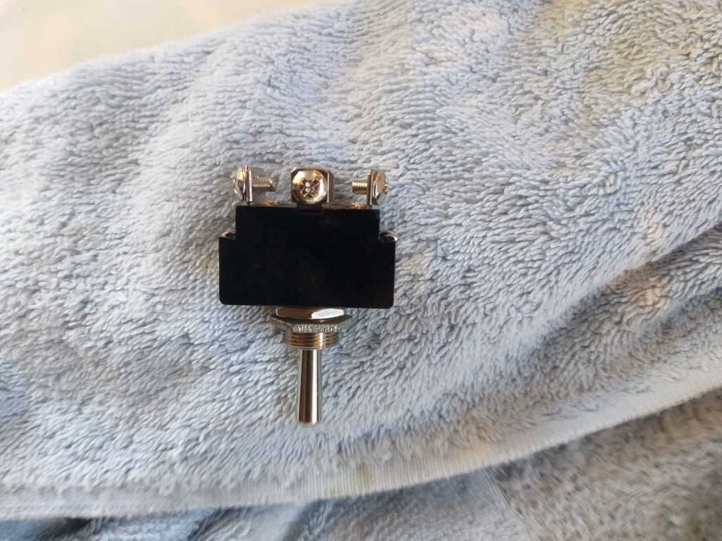
If you're using a toggle switch you'll need a single pole double throw. I'd use a double pole/double throw ( https://www.jaycar.com.au/dpdt-6a-240vac-heavy-duty-centre-off-standard-toggle-switch/p/ST0576 ) so you can double up the contacts and not need to run a relay, i.e. keep it simple.
If you can confirm the terminals were correct in my previous post I'll draw you up a circuit diagram and a simple wiring schematic.
@sr2 that switch looks like a match for the one that I bought from Jaycar a while back for this purpose, but I'm no expert. Underside of switch looks like so:
You are also correct in that if I connect an earth to wire C, wire B is my low speed and wire D is high speed.

-
 1
1
-
-
Hold the phone fellas !
So the other day when @igor asked me if I had the original harness and switchgear from the donor van I quickly said no.
But looking at @Raizer's post showing an intermittent switch got me thinking some more and I suddenly realised that I'm using the wiper motor out of my older SD series donor van instead of the one out of my newer SJ series van which I left the wiring loom in.
So, yes, I do still have the mostly intact SD series wiring loom. I've pulled it out of the dusty corner of my shed and behold it does have a controlling box similar to the image that @Raizer posted.
I can't remember if I sold the column-based wiper switch from this van or whether it's still lying amongst my parts, but maybe I should see if I can figure out how this controller is wired up before we go any further.
-
5
-
 1
1
-
-
Okay all, I've done some experimentation on this and @sr2 is correct in that I can reverse the polarity on the wires and the two speeds still work with the only difference obviously being that the motor turns in the opposite direction.
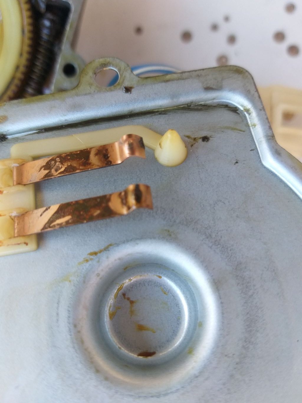
I then opened up the "gearbox portion" of the mechanism and I've been able to ascertain that the park switch is of the normally open variety.
It uses these two "fingers" to close a circuit when the rotation reaches the outer contact:
So it looks like @sr2 is on the money in terms of me having to make up a "box full of electronic trickery" to get the park function to work, especially considering that I want to control the main functions through a simple double pole on-off-on toggle switch.
Simon, it you are able to put together a solution for me I'd be eternally grateful as my OCD just can't cope with the wiper blades stopping any old where.
-
2
-
-
- Popular Post
- Popular Post
Now "fun me" wanted to crack straight into the a/c hoses, but "serious me" decided that since we are now deep in our rainy season getting the wipers working again should be top priority - not to mention getting the windscreen sealed properly.... but that is another story.
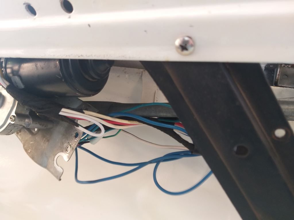
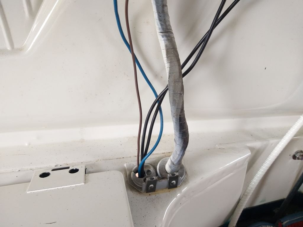
So those of you playing along at home would have likely spotted the shocking condition of my under-dash wiring:
Yep, not pretty at all.
The plan has always been to get all of the additional wiring for the mod cons in and then do a final tidy up, but with just the two a/c related wires left to run there is no time like the present to tackle the rat's nest.
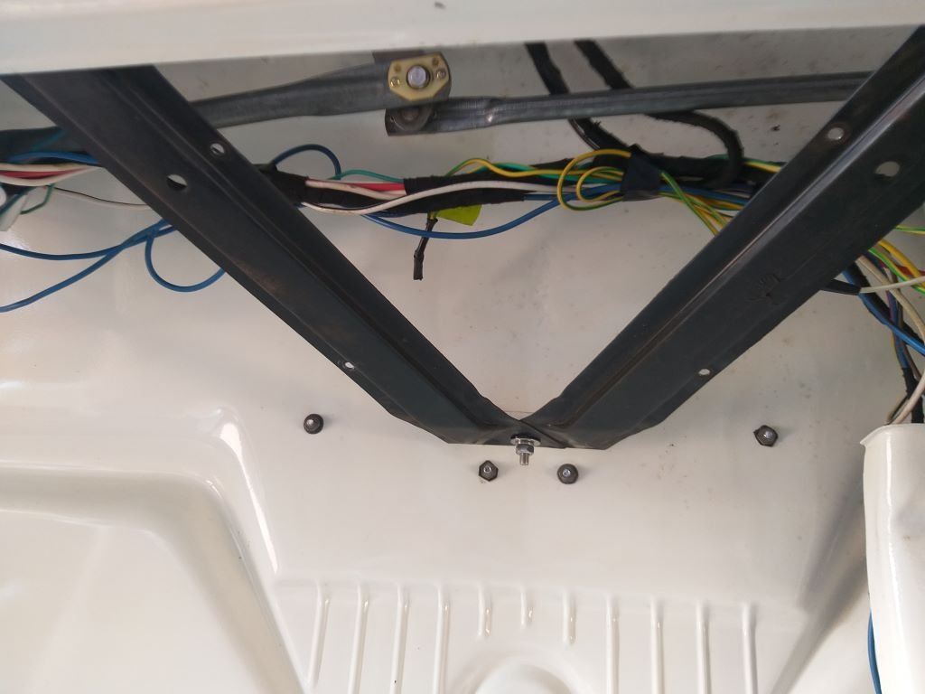
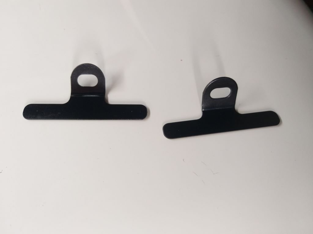
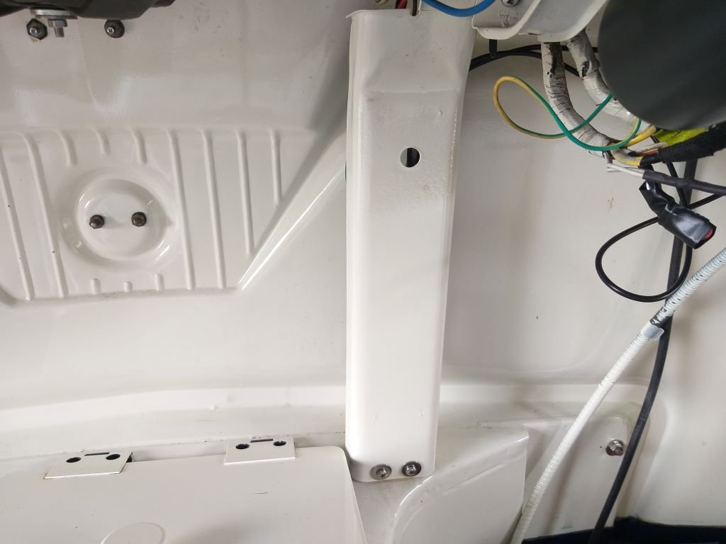
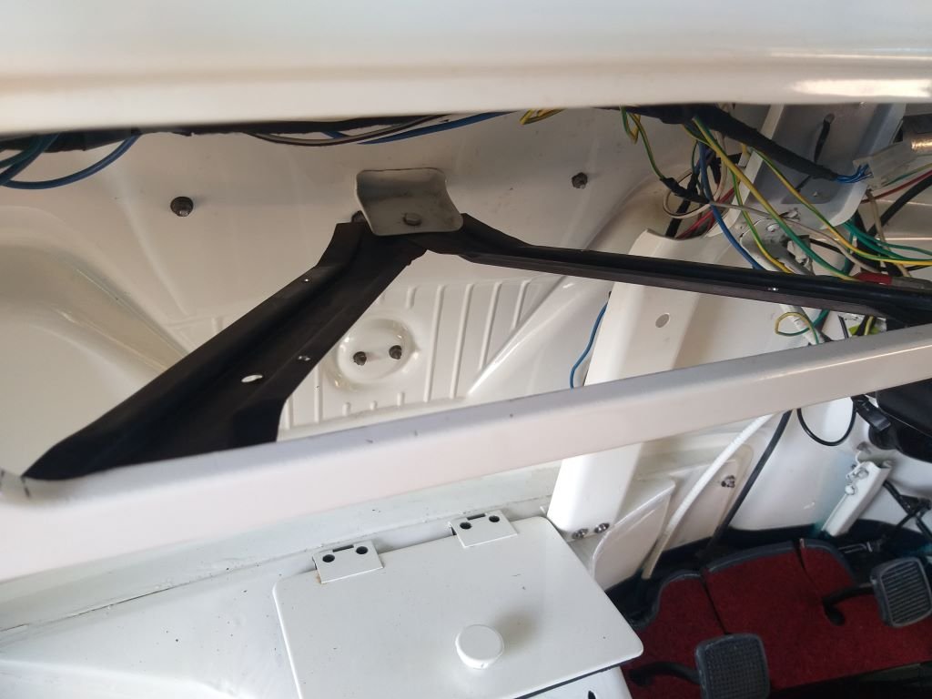
First order of business was to get everything out of the way of the new wiper mechanism, so I scratched around in my parts bin and came up with two little metal brackets that came from one of my donor vans. Gave them a quick clean and a spritz of satin black and they now look like so:
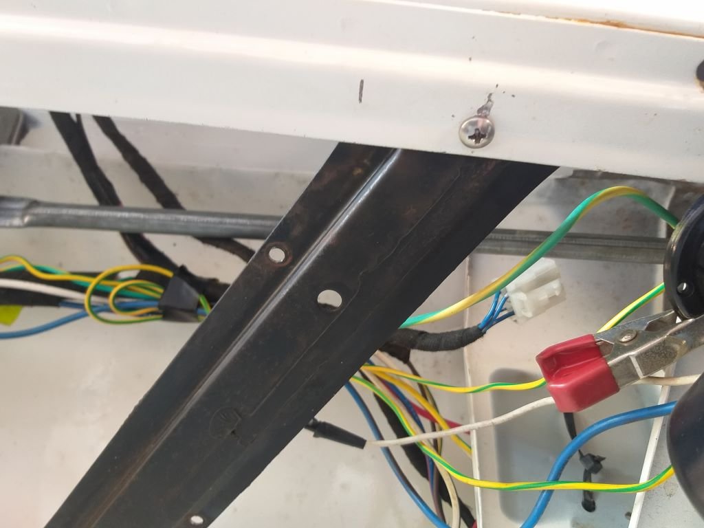
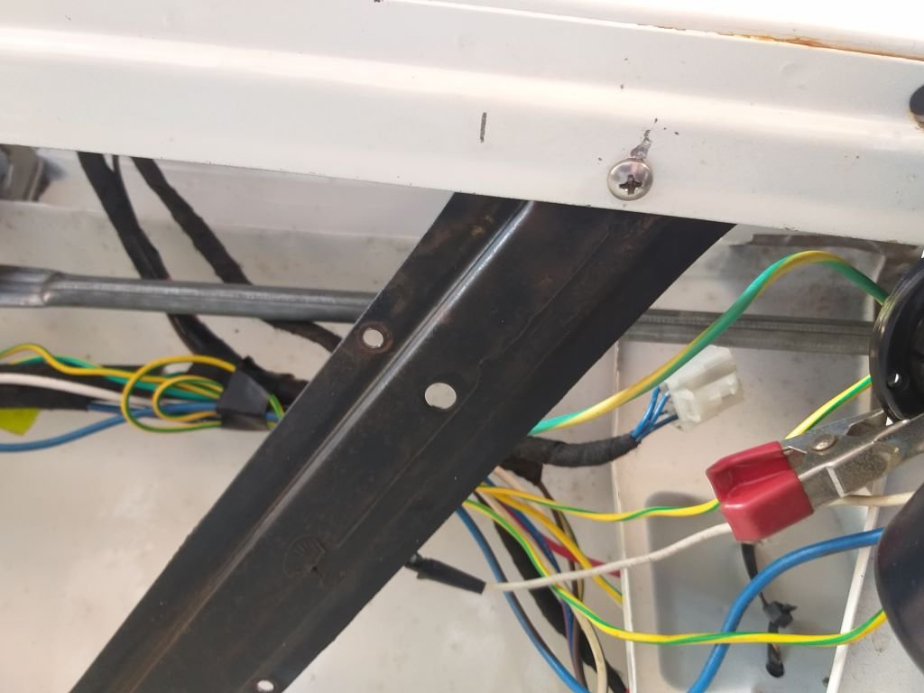
I then grovelled under the dash one more time and managed to poke two more holes in the front panel lip. Threw two self tappers at the brackets and wrapped a bit of spiral bind around the wires and she looks much better now:
Once I've added the two a/c wires into the spiral bind I'll use some cable ties to secure the loom to the holding brackets.
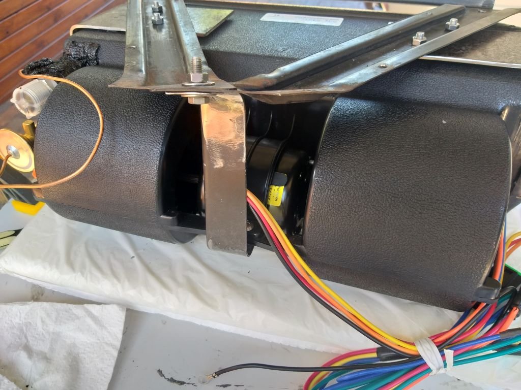
Anyway, with the wiring loom now safely out of reach of the wiper mechanism I was finally able to mount the wiper motor in position.
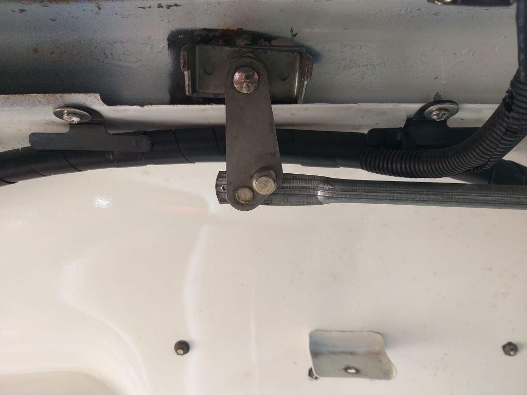
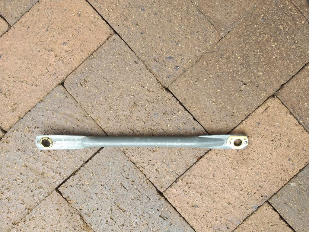
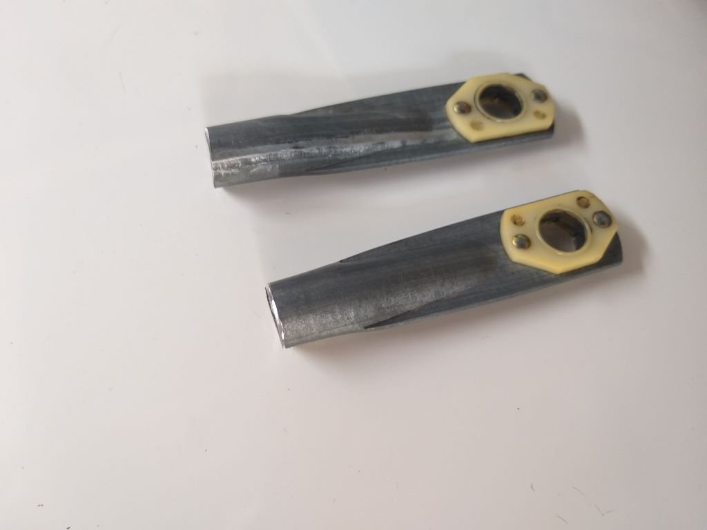
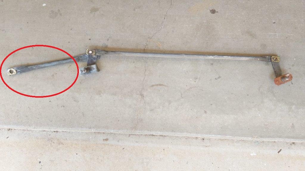
The last wiper related mechanical step was to shorten the length of this drive shaft to suit the new motor position:
So out came my grinder of angles and I ended up with this pair:
Scratching around in my pipe stash yielded a piece of aluminium tube that slips over each of the cut ends perfectly.
I spent a bit of time fine tuning the length of the aluminium joiner till I got the movement spot on. Gave everything a test run and it works brilliantly. Unlike the Thames mechanism which was quite jerky the L300 setup is silky smooth.
Flushed with success I'm now attempting to get the park function working as up to now I've had to time my switching to get the wipers to stop in the correct position.
The wiring for the park function is currently doing my head in so I've shouted out for help on the General Car Chat page and I've already received some good info from a number of old schoolers. So hopefully I can get this sorted too.
Some more work on the wiring tomorrow and with a bit of luck I can get on to the a/c hoses later in the weekend.
Thanks for looking.
-
10
-
46 minutes ago, Hyperblade said:
So since it's of the same era. I've wired up a 84 Toyota starlet motor from scratch before, which was a pain.
Here's a starlet wiring diagram.
\
In my case I needed a 4 pole switch (not cheap e.g. $80+) to allow it to park correctly, getting off/low/high is the easy part.
It is ground based.
The wiper motor needed 12v and 3 wires from switch.
Pin Terminal Cable Destination Description 1 12v 12v Light Blue 2 park Light Blue/White 3 low Light Blue/Red 4 high Light Blue/Black Then the switch needed 12v as well then 3 wires to the wiper motor and you have to jump 2 of the pins (dotted)
Pin 2: Park
Pin 3/4 connected via jumper (dotted)
Pin 5: Low
Pin 10: (not sure can't read what I wrote, I think it livens up the other circuits within the switch
Pin 11: 12v source
Pin 12: High
Thanks heaps for this info @Hyperblade I've got some homework to perform tomorrow.
-
1
-
-
1 hour ago, sr2 said:
Most 4 wire wiper motors I've come across have the earth through the body, and terminals for a continual 12V supply, high and low speeds and an on/off. Not too hard to work out which terminal is which with a 12V supply.
@sr2 thanks for the reply Simon. Looks like Mitsubishi do something different as earthing the body and then cycling +12 volts through the other wires yields no results on three of the wires and sparks on the 4th wire.
-
1 hour ago, Doug Hill said:
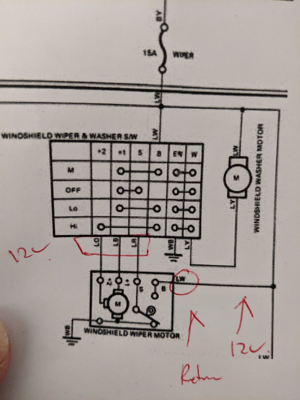
C should be +12v
The other 3 should be a lucky dip of earthing via the switch to get park/low/high
Thanks heaps for the guidance @Doug Hill. Test results below:
With a power feed connected to wire C, earthing wire B gives me low speed, earthing wire D gives me high speed, but earthing wire A does nothing.
-
Good suggestion @locost_bryanIt's off a SD series Mitsi L300 van circa 1985.
-
22 minutes ago, igor said:
If you have the switchgear and appropriate bits of the loom from the donor vehicle that might be a good start.
(I'm not a sparky so there may be something obvious that I'm not seeing.)
No such luck @igor
-
 1
1
-
-
I'm trying to figure out how to wire up this two-speed wiper motor and to get the park function to work without blowing the bloody thing up.
Please help a brother out.
-
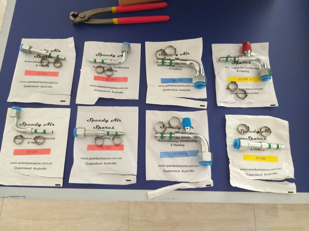
Couldn't wait to unpack my a/c hose fittings. I've gone for the DIY Air-O-Crimp option.
It's the first time that I'm going to be making up my own a/c hoses, so I reckon I'm in for an interesting time.
-
5
-
-
- Popular Post
- Popular Post
By yesterday morning my freshly painted a/c mounting brackets were dry.
Quickly mounted the under-dash a/c unit for what is hopefully the final time and then set about working out my hose requirements so I can get my order in with Jeremy the a/c man before he closes up for the festive period.
As mentioned in one of my previous updates I was hoping to bring the hoses up into the cabin behind the false panel that covers the wiring loom, but on looking underneath the van a portion of the underside of the floor is made up of a hollow structural brace that I'm loath to drill through. So, the only option is to bring the hose up on the LHS and loop them around to the right behind the unit. I'm thinking I'll replicate the false panel to hide it all.
Anyhoo that has increased the length of the hoses by a good meter each so it's good that I discovered it now. The rest of the pipework looks fairly straight forward although I am a bit worried about the compressor lines as the 90 degree ends that I have ordered may not suffice. But I'll burn that bridge when I get to it.
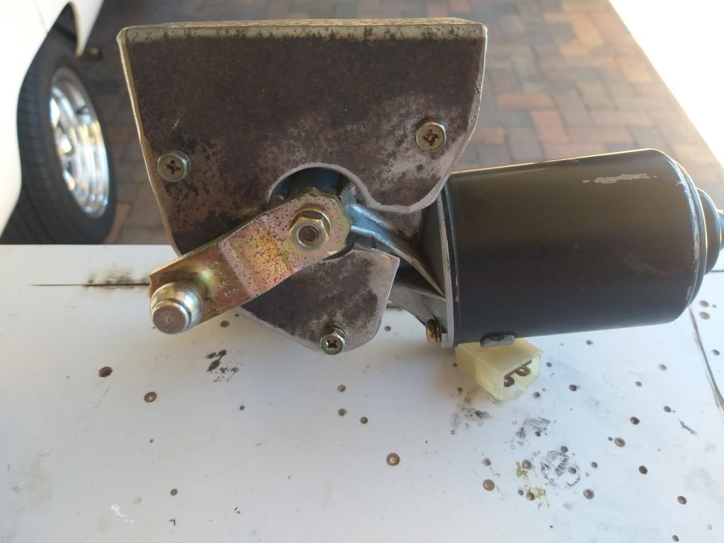
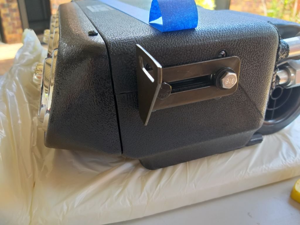
With the hose components all on order, I thought I'd tackle the wiper motor mounting bracket today.
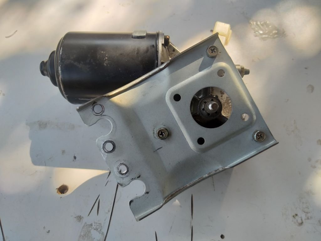
So first up I took a look at the original Starwagon factory mount:
Yeah nah, that helps me "sweet fanny adams", so looks like I'm up for some metal carving.
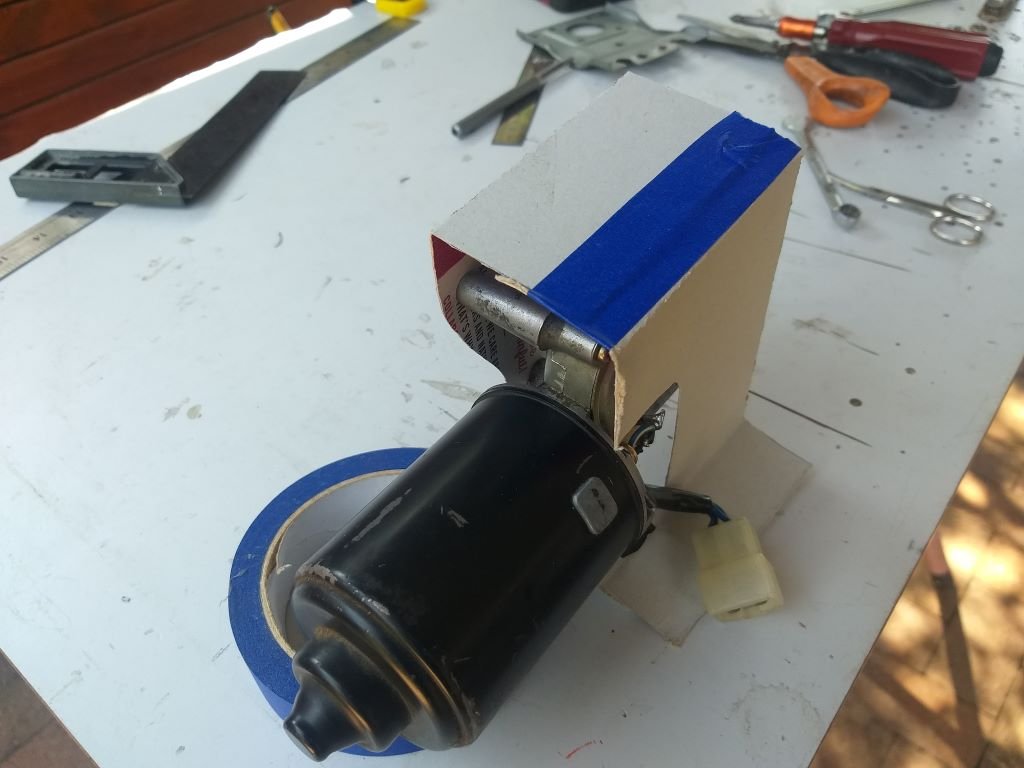
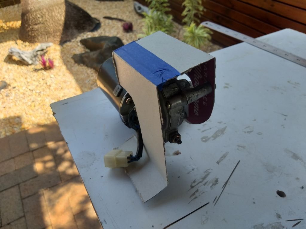
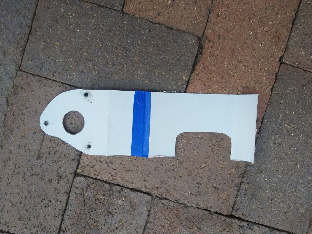
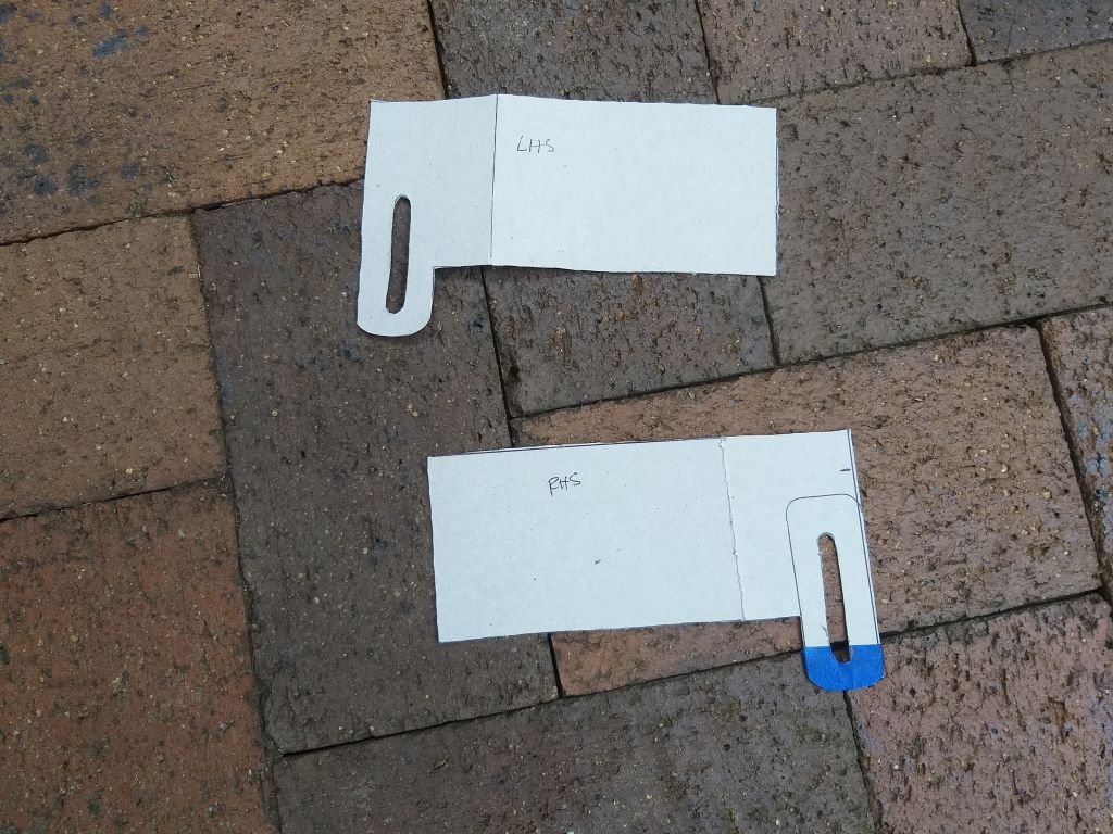
Started off with a little cardboard aided design and came up with this beauty:
"Why so complex Flash?" I hear you asking.
Well, the driving spindle needs to face the front of the van and the only mounting point that I have available is the lip on the underside of the dashboard located behind the wiper motor, hence this U-shaped monstrosity.
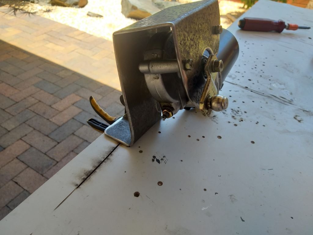
Next step was to replicate the bracket in something more solid than an old cereal box:
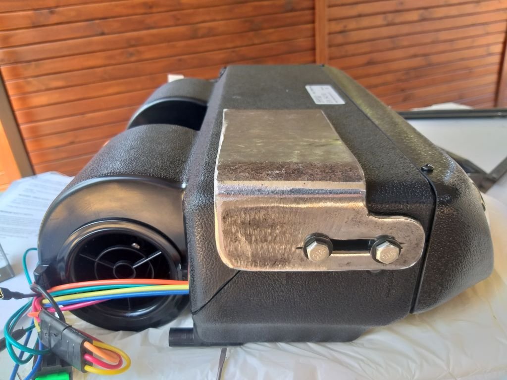
After a bit of the old cutty, cutty, followed by the poking of a few holes and here she is in all her glory:
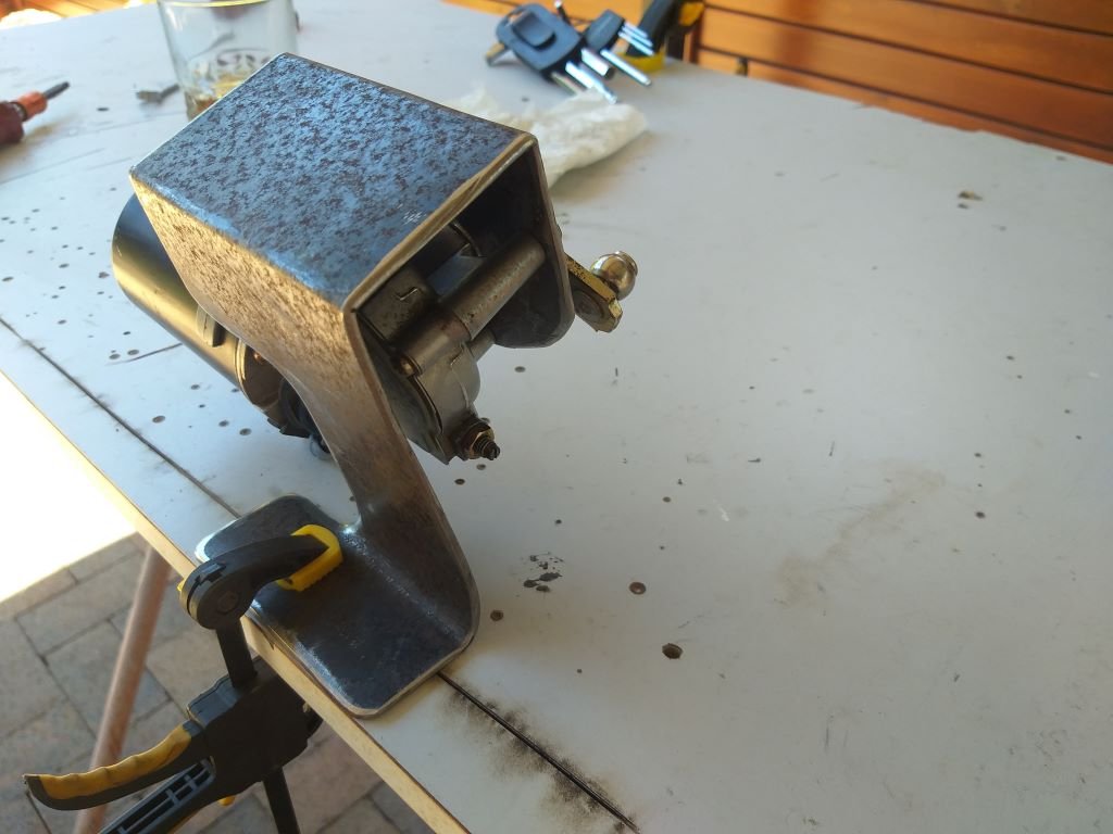
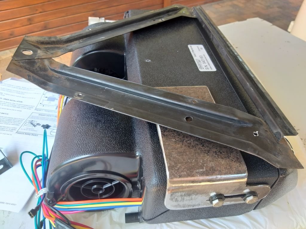
Had to play around with the angle on the mounting tab to get things to line up properly:
Temporarily clamped it in place. The good news is that it just fits between the fuse box and the glove box opening.
I then offered up the little drive shaft, but it's way too long, so that is going to need a bit of nip and tuck surgery.
That will probably have to wait for a few days as I've just received notification that my a/c hose components are ready for pickup, so I'll head through to town tomorrow.
Thanks for looking.
-
10
-
Most of the late 70s and early 80s Porsche 911s were fitted with K jet systems so I would give Stu at Aero Automotive a try. If he can't help I'm sure he will know someone who can.
-
- Popular Post
- Popular Post
And that's the holes drilled so that my a/c mounting brackets bolt up to the glove box bracket.
I wasn't happy with the puny looking rear mounting bracket that came in the a/c kit.
So, I spent a bit of time making up my own rear bracket in true "Rough & Ready Restos" fashion.
With all of the mounts completed I slapped the glove box bracket back in position and then bolted in the a/c unit.
I'm pretty chuffed with the result. It doesn't look too out of place.
The other good news is that the gas lines are located on the RHS of the unit which means that I can hopefully hide them behind this panel:
The panel currently hides the main wiring loom and a few additional circuits that I have recently added. I whipped it out to see how much space is left behind the panel.
Looks like I should be able to squeeze the a/c pipes in between the wiring loom and the front panel. I've still got a few additional circuits to add (including some a/c related wiring) before I can wrap my extra wiring loom, but hopefully that will neaten things up too.
Thanks for looking.
-
13
-
- Popular Post
- Popular Post
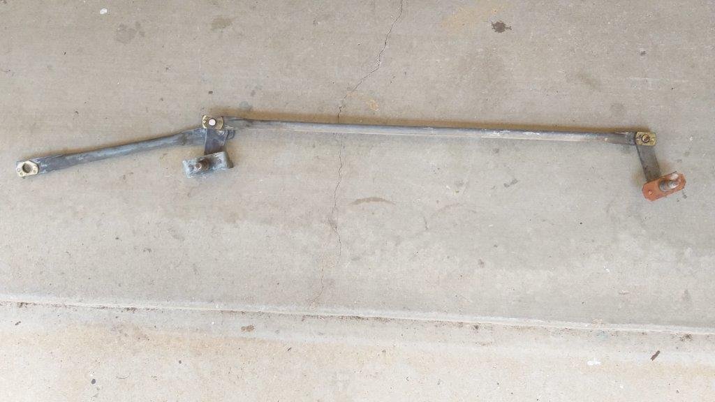
Next step from a windscreen wiper perspective would be to fabricate a mounting bracket for the L300 wiper motor. Now I'm thinking that I can fine tune the positioning of the motor by either shortening or lengthening this intermediate drive shaft.
And hopefully that shouldn't affect the sweep in any way. Feel free to correct me if I am wrong.
I figured it would be better to finalise the glove box and under dash a/c unit installation and I can then position the wiper motor in the space left over.
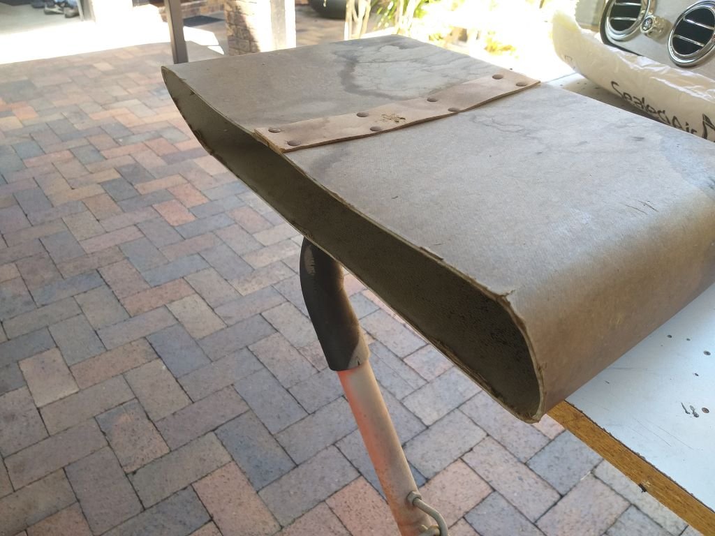
So the first step was to retrieve the dusty old glove box for closer inspection. It's a bit grubby but still looks functional.
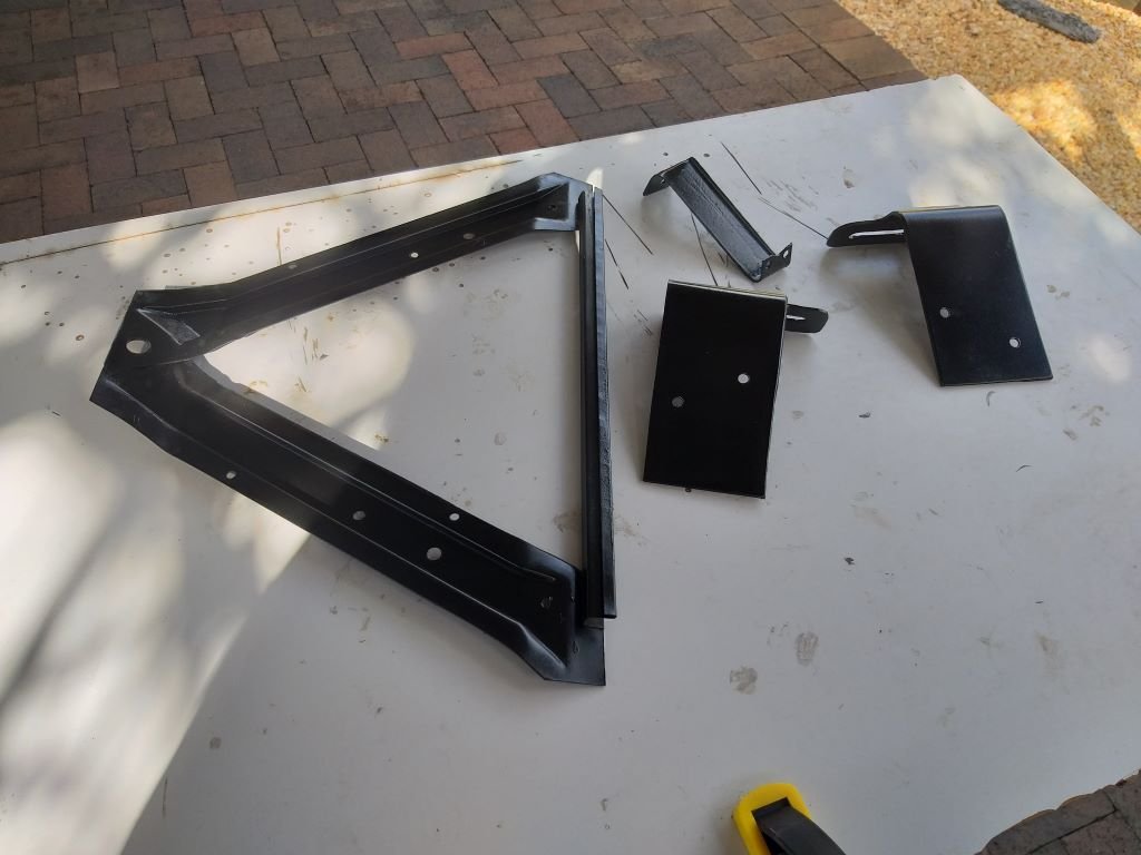
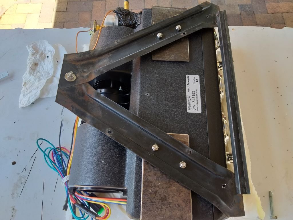
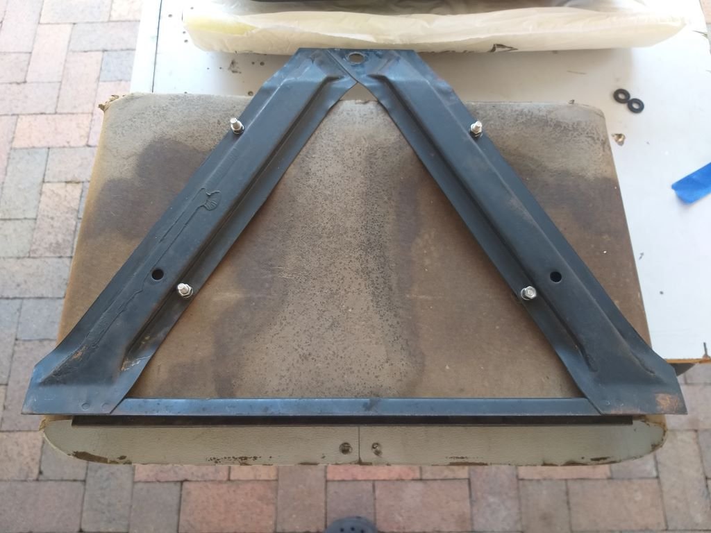
The underside of the glove box has a nifty mounting bracket that looks like so:
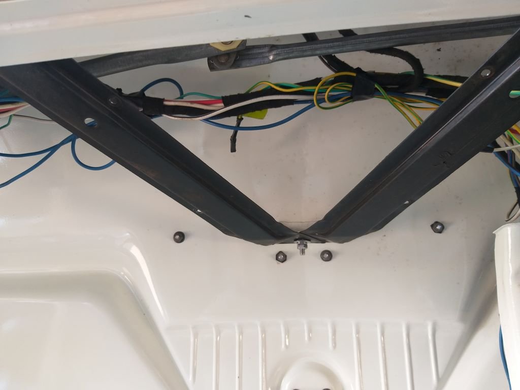
The pointy end of the triangular bracket mounts up to a little bracket welded to the inside of the front panel with the longer side resting up under the lip on the dashboard, like so:
Now I'm thinking that refitting the glovebox has the added advantage of allowing me to use the same mounting bracket to support the under-dash a/c unit. But in order to do that I need to add some fixings to the dash lip to make the bracket more rigid for the additional weight. I poked two extra holes in the dash lip and added some stainless-steel self-tappers and it's nice and solid now.
Next step was to take a closer look at the mounting brackets supplied with the a/c unit:
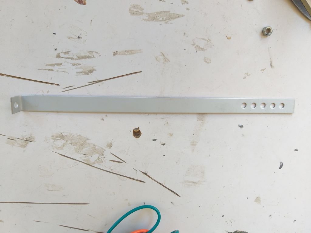
Those definitely aren't going to work for me, so I spent a bit of time doing some CAD and came up with these:
Grabbed some 3mm plate that I had in stock. Did a bit of cutting, did a bit of bending, poked a few holes to replicate the mounting slot and I ended up with two of these:
And the plan is to bolt my newly fabricate brackets to the factory glove box bracket in more or less this configuration:
So, the plan for tomorrow is to mount the glove box bracket back in the van and then offer up the a/c unit so I can work out exactly where the holes for my mounting bolts need to go.
Stay tuned for the next exciting episode.
-
14
-
- Popular Post
- Popular Post
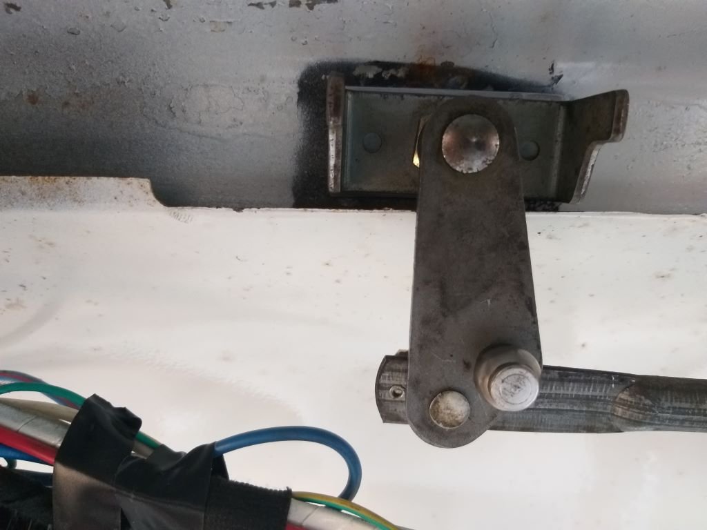
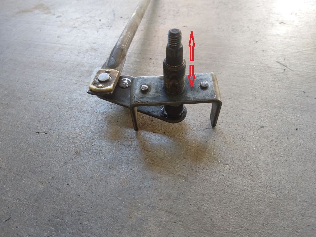
Started the morning off by fitting the freshly painted spacer to the LHS wiper spindle and then bolted the mechanism in place.
Managed to get a clear shot of the factory seam that I was talking about yesterday:
As you can see the factory had already trimmed the seam in the area of the spindles and I'm guessing that was done to provide the needed clearance for the Thames spindles, but just wasn't enough for the L300 ones.
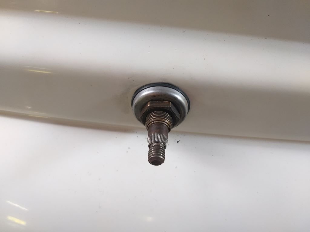
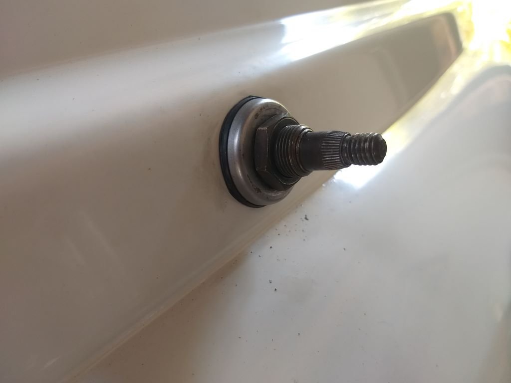
As you can see in the below photos there is still plenty of depth to the spindles even with my extra spacer.
I'm liking the rubber seals and shaped washers that came with the L300 units. If the Thames units ever had rubber seals, they are long gone.
As can be seen the splines and threads are also in perfect nick.
With the spacer in place I chucked one of the L300 wiper arms on and Mrs Flash held the manky old wiper blade slightly off the windscreen while I climbed under the dash and manually manipulated the mechanism. The good news is that the LHS wiper sweep looks to be really good. The angle on the L300 wiper arm looks good, but the L300 blade is too long and goes well over the windscreen seal. Should be easy enough to source shorter wiper blades.
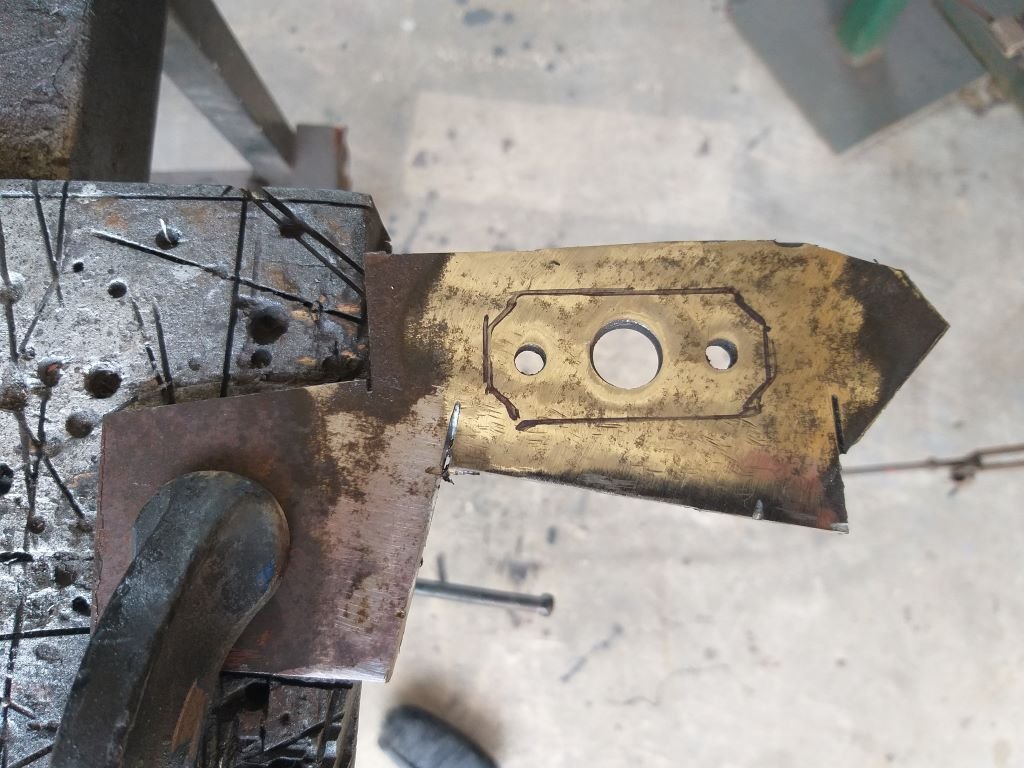
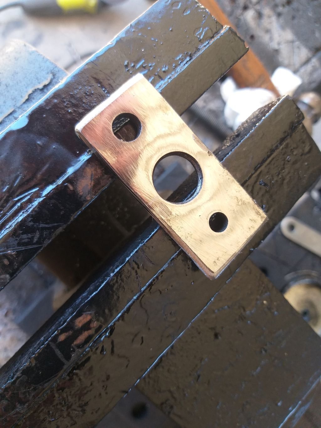
Spurred on with the success so far, I proceeded to make up a spacer for the RHS spindle.
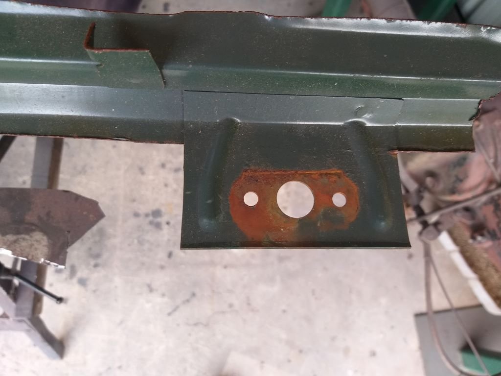
In order to explain why my spacers have the extra little locating holes on either side of the spindle hole I'll share this photo of the original L300 front panel that I kept when I wrecked that van:
My guess is that they prevent the spindle backing plate from rotating by holding it firmly in place.
Anyway, a quick "in progress" shot of the next spacer which has now been completed and has received its first coat of galv paint, so I thought I'd update you all on progress while the paint is drying.
-
11
-
- Popular Post
- Popular Post
Okay, so whilst a big part of me just wants to concentrate on finishing off the a/c install, I've realised that there are a few dashboard related items that need to be addressed before I fit the under dash a/c unit.
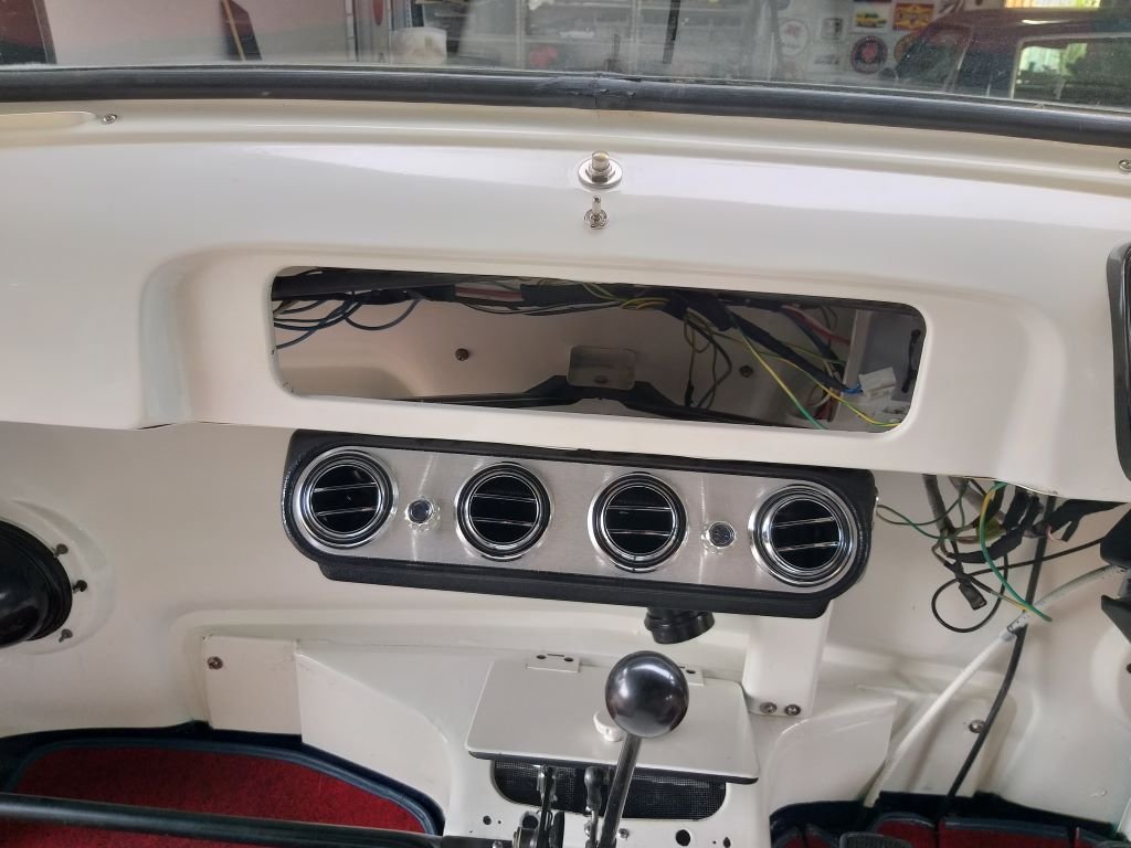
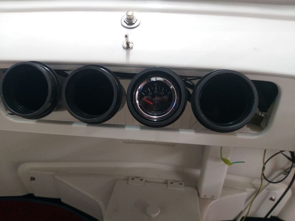
First up you may recall that we deleted the factory glove box and filled the opening with housings for some additional gauges. Photo of what we currently have which while functional looks bloody awful:
A few months of driving around with phones, sunnies, wallets and various other bits and pieces either sliding off the engine cover lid every time we take a corner or languishing in the passenger footwell has become tiring. So, a decision has been taken to reinstate the glove box and move the gauges elsewhere. But more about this later.
The more pressing matter is the current windscreen wiper setup which only really got used in anger two weeks back when we had the first rains in about 6 months. They managed a trip into town, but on the way home they suddenly seized up. Luckily the worst of the rain was over by then, but still this needs to be addressed now as it will be a real bugger to access the wipers once the under dash a/c unit has been mounted.
So, without further ado, I pulled the wiper mechanism out to see what is going on.
Yep, that doesn't look to flash. Now I had noticed a bit of play in the original wiper spindles particularly the passenger side one which I stupidly decided to ignore at the time and it looks to me like the spindle in question snagged up and the resulting torque of the motor did the rest of the damage.
With a bit of effort, I could probably re-bush the units, but the second issue is that the splines have taken some hits over the years and since the wiper arms are just push on units the fit feels a bit dodgy. The answer would be to source a set of pivots in better condition, but what are my chances of finding good ones especially considering the vast majority of used parts would come from the UK where rain is slightly more common an occurrence than here in Straya. So, my chances of finding replacement Thames pivots are probably nil.
The third issue is that the tubby 2 speed wiper motor that I have fitted to replace the original svelte looking vacuum unit now clashes with the glove box inner, so I'll need to modify the inner to clear the motor. The chances of my 60-year-old cardboard glove box inner surviving nip and tuck surgery are slim.
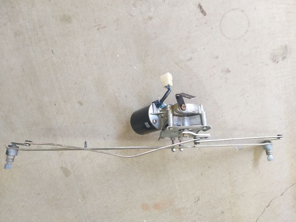
So considering all of the above I've decided to take a different route and it just so happens that I have this mechanism out of a Mitsi SD series L300 van languishing in the shed.
Way back when I was stripping my donor vans, I noticed that the SD series mechanism shared the exact dimensions with the Thames and at the time I did successfully do a test fit of the L300 unit which bolted straight up, but at the time I thought the Thames one was a simpler option as I didn't have to shorten the wiper blade arms. Checking out this mechanism the spindles are mint, just needed a bit of lube to make them perfect.
I bolted it into the van and apart from having to shorten the blade arms and fabricate a bracket for the wiper motor, the only other issue is that the LHS "conrod" hits the metal seam where the windscreen surround butts up to the front panel. Even although the seam is hidden under the dash I don't want to butcher it. Luckily the L300 spindles are a lot longer than the Thames units so my cunning plan is to make up a spacer for each pivot that will space the "conrods" away from the seam.
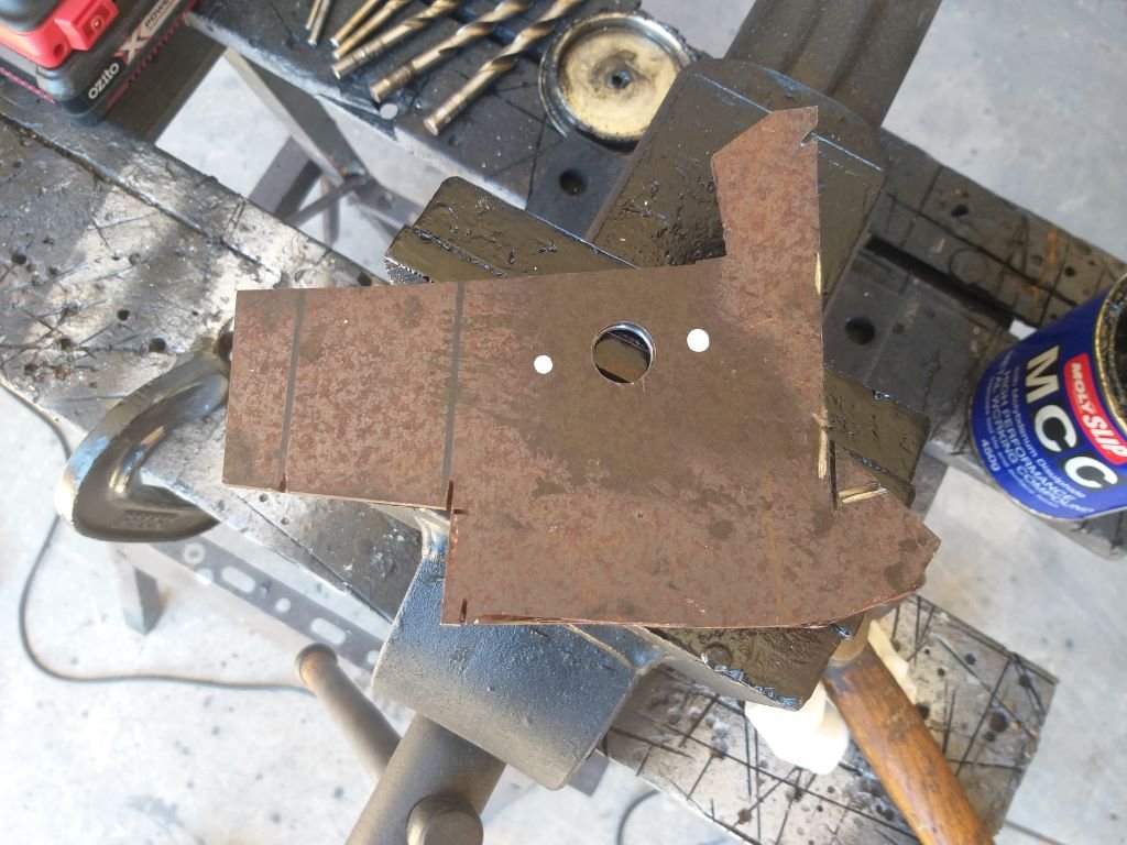
Not too much of an issue I reckon. so I started off by making up the first spacer out of an offcut:
Poked a few more locating holes and trimmed to suit:
Have given it a splash of galv paint which I've left drying overnight. If the test fit works out okay I'll make up a second one for the driver's side.
Thanks for looking.
-
11
-
- Popular Post
- Popular Post
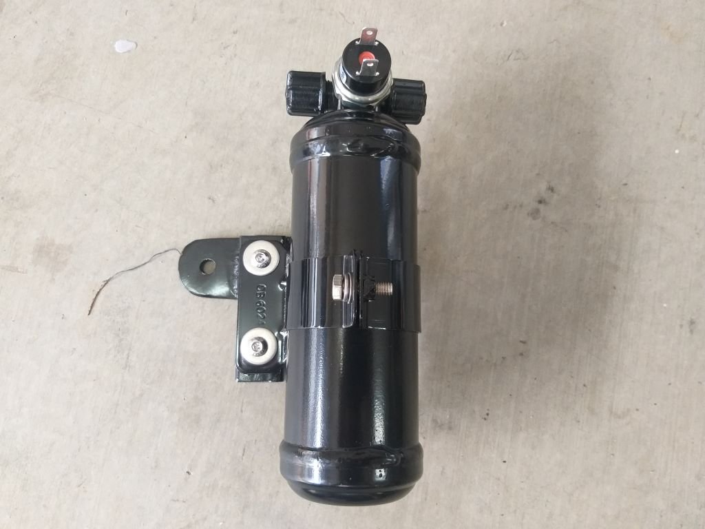
First thing this morning I fixed my newly fabricated receiver bottle mounting bracket to the bought one with a few stainless-steel fixings. Screwed in the pressure switch and she is ready to go.
Grovelled around in the wheel well with a few spanners, and then:
Next on the list is the under-dash unit.
-
10
-
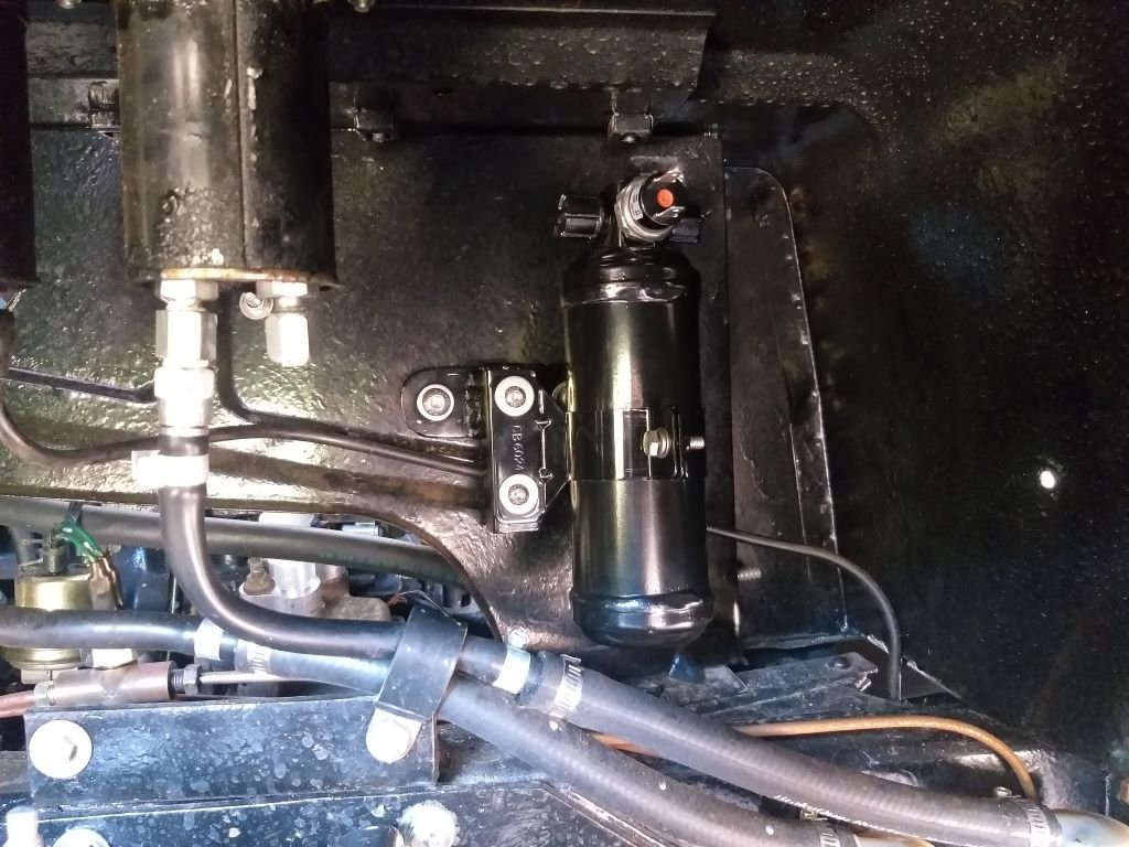
I promised to share my receiver/drier mounting bracket efforts with you all, so here goes.
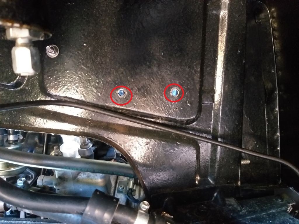
The plan is to locate the drier in the RHS front fender well tucked up above the chassis leg. I decided to make use of the existing bolt holes that mount the coil in the engine bay because if I do go to an electronic distributor sometime in the future the coil will become redundant leaving me with empty holes which will mess with my OCD.
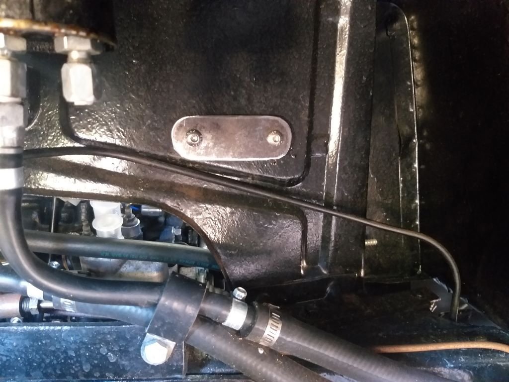
So the first step was to carve a little flat plate out of a steel offcut, and I then poked a few holes in said plate.
Test mounted like so:
The eagle eyed amongst you will likely spot the hydraulic clutch hard line that sits slightly proud of the side even although it has its own factory formed channel to live in, hence the need for the mounting / spacer plate.
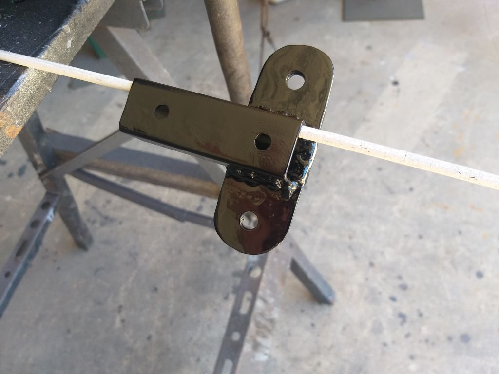
Next step was to fizz a bit of square tube to my newly carved mounting plate and after a spritz of satin black I ended up with this puppy:
I've left it to dry overnight, and I'll assemble it all in the morning.
-
9
-
-
I'm back on the a/c install.
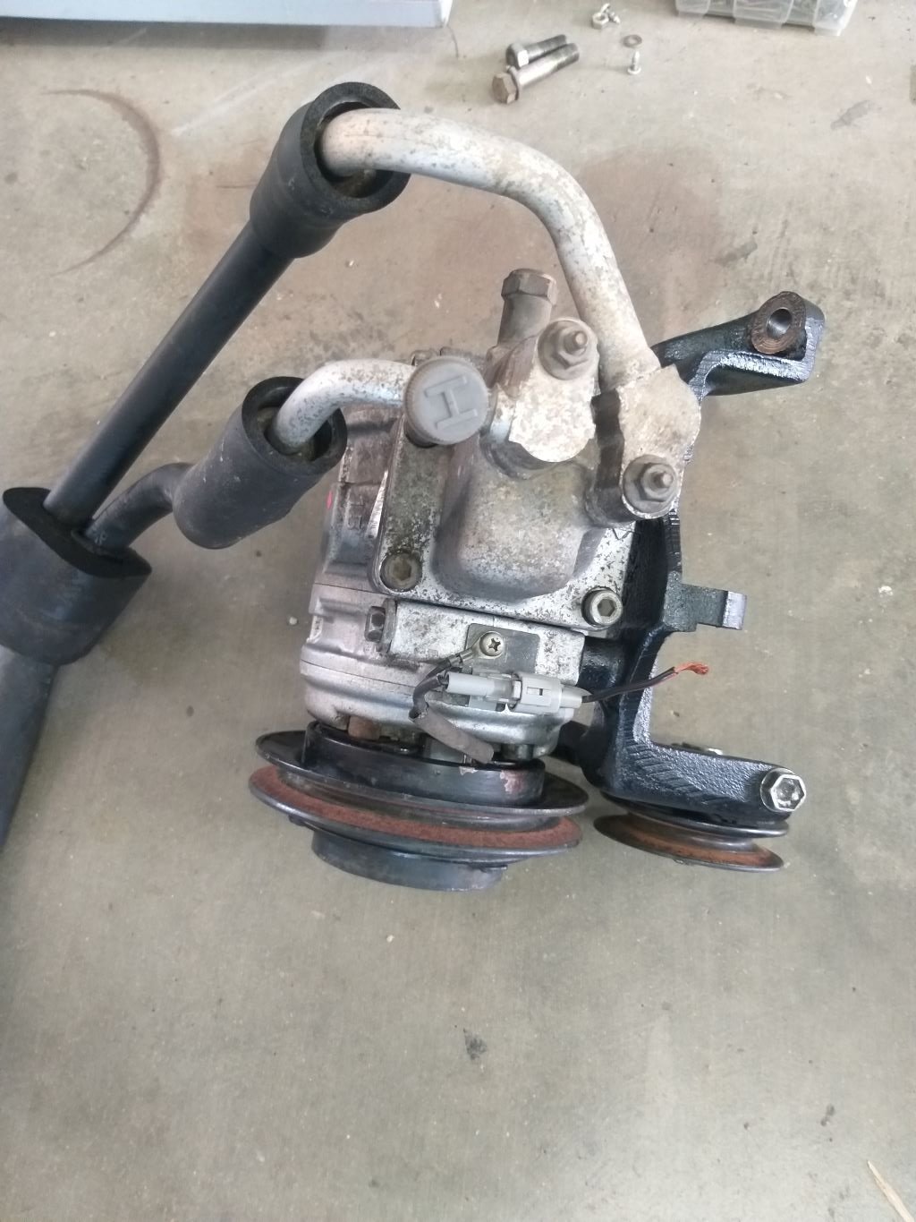
Today's task was to build a mounting bracket for my receiver/drier bottle, which is all done now, and I'll show you it in all its glory once the paint has dried, but in between coats I thought I'd tackle the a/c compressor inlet and outlet swaps.
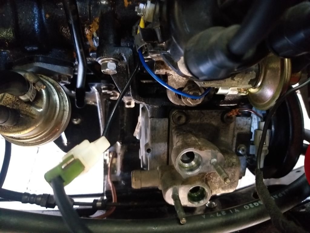
So, when I grabbed the compressor from my local wreckers I nabbed the inlet and outlet hoses at the same time.
There are two issues with these hoses.
First up the hard portion of the lines bend towards the side and wont clear the chassis leg on my van. Secondly both lines face forwards which makes sense for a standard a/c install where the condenser sits forward of the engine but in my case where my condenser is mounted underneath and towards the back of the van, I need the appropriate hose to face rearwards.
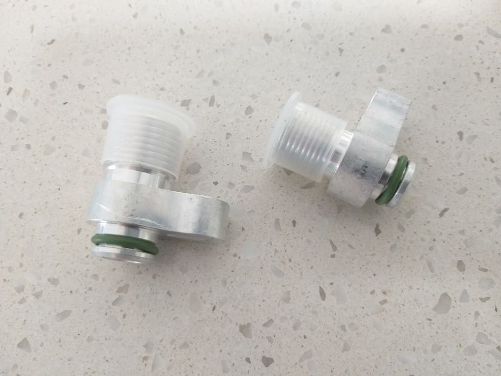
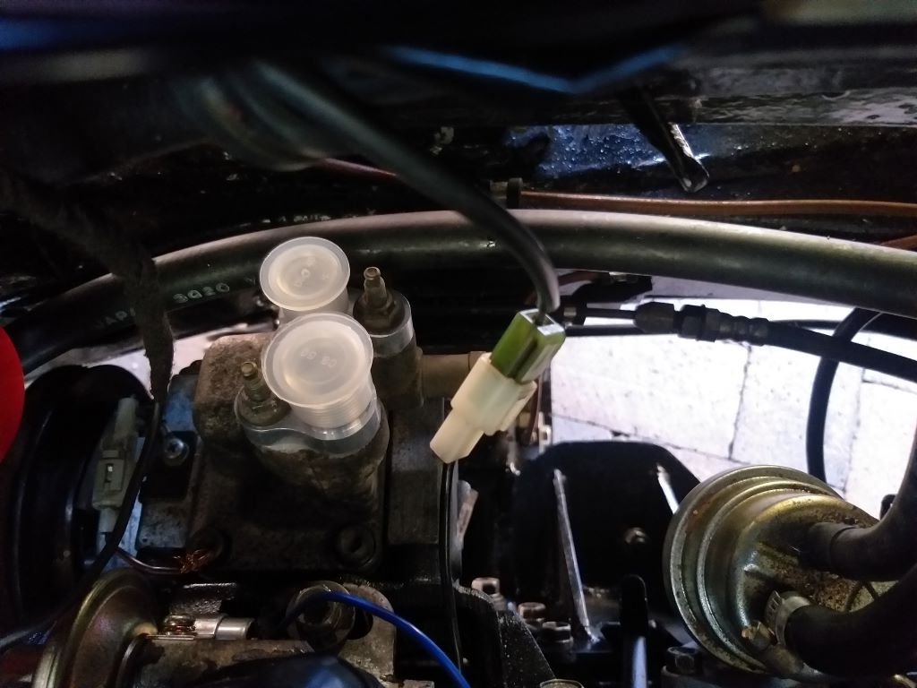
I was able to solve both issues by sourcing a set of pad to o'ring adapters specifically for the Denso compressor.
After giving the o'rings a bit of lube I was able seat them in their new home:
And that's the compressor all done until I start fabricating my hoses.
-
7
-


Wiper motor - wiring up the park function
in General Car Chat
Posted
Thanks Tori. I'll dig through the rest of the loom tomorrow.