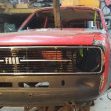
Hurmeez Posted August 3, 2018 Author Share Posted August 3, 2018 I made a trip to the wreckers for a browse, looking for a center section for my diff and other miscellaneous stuff and took a tape measure with me. Using that I managed to find this: This just so happens to be the largest radiator I could possibly fit. It has about 5mm clearance on either inner wing. As you can see I'll need to completely re-engineer the radiator support/anti-roll bar mount cross member and the side panels, and the radiator hose will have to do a couple of tight turns to get around the anti-roll bar as well but other than that it's pretty much perfect. It has no radiator cap in the top tank, just like the original rad out of the Mazda, the bottom inlet is on the correct side, it is thicker than the original Mazda and compared to the original Escort rad, It probably has twice the effective area. So the combination of size and the modern design means that with a couple of fans there should be no way in hell that I'll overheat it at all. I would be absolutely astounded if anyone is able to tell me what it came out of. In fact, I would bet money that you couldn't guess. Additionally, I've been knocking some suspension ideas around in my head. Being young and dumb and full of the proverbial, I know there'll be the occasion where I want to make a speedy exit of an intersection or leave a traffic light hard or something. I've seen people try this on leaf springs and the axle tramp that results is often quite embarrassing. Now I'm no stranger to embarrassment but I do prefer to avoid it if possible, along with the hammering that the axles get when the occasion arises. So ideally to avoid this I'd need a four-link of some description. Yes, I'm aware that anti tramp bars exist but from what I've seen and read, they're not really that effective and the effort to go from installing them versus a full four-link isn't a huge leap. But then my annoying requirements come in and complicating everything. I really like the idea of the car looking fairly bog standard from the outside and retaining as much factory functionality as possible without sacrificing any for the upgrades. Specifically, in this case, the folding rear seat. In Escort estates, as with most station wagons, the rear seat lifts the base up and forward and lays the back down in its place to form a larger cargo area. If I was to use standard four-link boxes they would end up in the same place at the seat base. Even if I used the earlier style with shorter arms, they would still intrude too far into the cabin to allow the standard rear seat functionality and so according to my requirements, they're out too. For a while, I was stumped. Then I thought, why not use the raised rear floor to my advantage? Who says I can't send the top arm backward instead of forward? So I made a quick little scale mockup to see if it could work. I end up with about 75mm bump and 50mm droop with very minimal axle deflection at either extreme of travel. This being so small scale it's difficult to rely on the accuracy but I ran the numbers through my old physics workbooks from last year and the Watt's link type off effect shouldn't cause the axle to twist significantly over this sort of travel distance so the driveshaft angles shouldn't be a factor to worry about. This GIF shows a mock-up driveshaft to illustrate this. I'd probably use standard style turrets set back far enough to not affect the latching mechanism of the seat and a typical Panhard rod or Watt's link for the lateral location. This is all just ideas at the moment. I'm interested in your guy's opinions. Let me know what you think here: 8 Quote Link to comment Share on other sites More sharing options...
Hurmeez Posted August 14, 2018 Author Share Posted August 14, 2018 After having a proper look at the rad I was starting to worry that maybe it would turn out to be too big and I was starting to consider a chin spoiler to cover up the rad poking through the front valence. I started pricing one up and found that it would be $250 for a brand new fiberglass repro or the same for a slightly sad original rubber one. Then I thought, why spend $250 to fit a $65 part when I could find a rad that fits more easily for another $65 and spend less than half the money even with the wasted radiator. Before I wrote it off though, I checked the fit one more time and with a bit more fiddling I saw that I'd be able to make it work. It'd be tight, but it would work. So I set to and made a CAD template. This shows just how tight I have to make it with the cutout to get around the bottom hose inlet. Then I transferred the template to steel and started forming everything. I opted to use 2mm plate for doubler plates for the captive nuts behind the ARB mount brackets. Ultimately I probably should have just welded the corners and done a few stitches because the warping that I got was a bit more than I would have liked, even with moving the heat around and not letting any one area getting too hot. Then it was the captive nuts. Then I had to try to fold it without using the brake because it was too long. In hindsight, I should have made it in two pieces and welded it in the middle but I didn't think of that at the time. I made it work in the end anyway. The first mockup went pretty well. It fits in the gap anyway. Next, I had to make the cutout for the bottom hose. Holesaw: Grinder: Paper: Steel: Somewhere along the line someone messed up a measurement and the inlet was touching on the cutout so I smeared some neverseez around to act as a transfer medium to tell me where it was touching. It ended up being a fairly drastic adjustment with the bottom of the cutout moving down about 10mm before I was done. Unfortunately, I was head down bum up determined to make it work so I didn't take any photos but rest assured I made it fit. I also made up some pieces to locates the factory rubber mounts after modifying them to be far lower profile. I wasn't completely happy with the clearance between the cross member and the rad. It would probably end up with the core touching once it was properly mounted and that wasn't something I was going to be ok with. I sat and thought and tried to figure something out but ultimately I had to slice along the length of the top and narrow it by 5mm. The result left me much happier with the gap. There's approximately 10mm clearance at the closest point between the core and the cross member now. With that pretty well sorted, I had a look at the brace that would have run vertically between the slam panel and the original radiator support panel. To my surprise, there was actually a good amount of room to work with. I was planning on modifying this piece to just come forward and weld to the valence. Now though, I realised I could put another cross brace between the inner wings to make up for the panel I took out. So, cardboard: (I reused the template from before, hence the cutout) And then steel: With that done, the next job would be to make the top mounts for the rad. To do that though I'd need to put together my nice new slam panel to have something to build to. And that's where I got up to. It shouldn't take long to make up some small upstands to pick up the original rubber mounts so I'll try to get that done tomorrow. As far as my rear suspension idea goes, I found out why I haven't really seen it used anywhere else, despite how simple it looks to me. It turns out there are some dynamic aspects that I hadn't considered, all explained extremely well by this website: http://www.trucktrend.com/how-to/chassis-suspension/0804st-rear-suspension-design/ I'll save you the whole read and paste the part relevant to me. Quote Full Reverse and two-Forward/two-Reverse Link Systems If all you're looking for is simplicity of installation and you don't want a two-link, these systems are the ticket. We have all seen them at shows or on the road (you might even own one!), so we can't argue that they don't work. The best explanation that we've been able to come up with for these systems is that they are counterproductive. The suspension's job is to take energy that is being transferred into the tires from the ground and to properly transmit those forces into the chassis to be used to create more traction. A reverse link system, in which the bars mount to the rear axle and the rear of the chassis behind it, does just the opposite, and the two-forward/two-reverse link system is nearly unpredictable in how it transfers energy from the ground to the chassis. Even if you calculate every single point to an exact placement when designing one of these systems for your truck, you will still only end up with a driveable truck and not one that handles properly. Your only hope for performance with a reverse triangulated four-link is to limit the travel as much as possible and run a stiff spring and a stiff shock. Then, maybe you'll have the traction of a poorly set-up forward-facing link system. The best way to think about it is to understand that with a properly designed forward-link system the rearend is actually being pushed against the ground by the chassis. So any force that the rear end can use to push against the chassis will ultimately create more traction. With a reverse-link system, if the rear end were to pull down on the chassis there would be an equal loss of traction. Try this on a bathroom scale. Stand on the scale in front of a cabinet and pull up on the cabinet and see that your weight goes up according to how much force you are able to apply to the cabinet. Now push down on the cabinet. Your weight will go down to nothing fairly easily. That is what's happening on a reverse-link system. The rotating force of the tires driving the truck forward applies an opposite twisting force into the rear end housing, and that force is applied to the chassis behind the rear end pulling the back of the chassis down, thus negating any hope for traction. On paper, this design looks great because the pinion can be kept well within working limits. A quite desirable instant center can be calculated, and it seems to fit into the confines of just about any truck. The real negative effects are all dynamic, meaning that they are only noticeable when the truck is being driven and the more dynamics being applied, the less traction it has. So I guess that means I won't be doing that. I think for now I'll probably stick with the standard style rear suspension and be gentle on the clutch unless the road's wet. 4 Quote Link to comment Share on other sites More sharing options...
Hurmeez Posted August 17, 2018 Author Share Posted August 17, 2018 It did only end up taking a few hours but finding the few hours took a while. Never mind though. Started with the cardboard as per usual then moved on to the steel. As a bit of a side note, this is what happens when you use the wrong tip on the Rivnut gun without realising. After they were all done I welded them on and mounted the rad properly for the first time. It's solid as a rock now. I'm really happy with how it turned out. With that done, the front panels are almost all fabbed up. I still want to modify my original replacement radiator mount panels to tie the slam panel down a bit more solidly. I'll cut them somewhere along these lines and fold up a flange to give them a bit more strength then weld them between the inner wing and slam panel. I would have done them next but I wanted a break from the panel work and I've been wanting to have a go at the clutch system for a while now. So that's what I did. I bought a second-hand clutch pedal assembly from a wrecked RX-8 with the plan of essentially replicating it with the standard Escort pedal. This is the Mazda pedal on the left and the Escort on the right. You can see that with the pivot points in similar positions the pedals are actually fairly similar in length and shape. You can also see the pushrod, clevice, and pin that the Mazda uses to activate the master cylinder. This is somewhat different to the cable that the Escort uses but I think I can make something work. I started by assembling this assortment of bits: Which come together to make this: I fully welded the bracket and turned up a quick bronze bushing to take the clevis pin. It comes in handy having a bunch of Grandad's old boat building bolt stock around sometimes. This should last much better than the crappy plastic bush that was in the original Mazda pedal and remove a lot of the slop that was present. Then I welded everything together and cleaned it up. You can also just barely see the bush that I tapped in there. Finally, I assembled everything and had a look at how it was going to turn out. It turned out mint actually. I'm fizzing about how well I managed to pull it off. I threw the pedal back onto the box and mocked up the master cylinder in about the spot it looked like it wanted to be. It turned out that it would end up about 20mm further from the pedal than it would have in the Mazda so I extended the pushrod by 20mm. The rod I used was a little larger diameter than the original but it works fine. This is at full engagement: And full disengagement: I made a cardboard template for an extension to the pedal box that would mount the master cylinder You can see how close it's going to end up to the brake tower mounts. This won't be an issue though because the brake tower won't fit anyway. With the exhaust system and the radiator set further back than factory, it never stood a chance. My plan right now is to find a brake master cylinder that has essentially the same internals but has under and over mounting bolts. That way there'll be shitloads of clearance between the two. Then I'll put a remote booster under the dash or inside the inner wing or something. The plan for tomorrow is to turn the template into steel and start modifying the firewall to take the new pedal box layout. Should be sweet. 6 Quote Link to comment Share on other sites More sharing options...
Hurmeez Posted August 19, 2018 Author Share Posted August 19, 2018 So I said it should be sweet. Was I fuckin right or what?! I started by making each face of the new wing in separate pieces of steel and tacking them together. There was a time when I would have tried to fold it all out of one piece but it was much easier to do it this way. With it all tacked up, I snapped it off the pedal box and welded it fully. Then tacked it up again and welded it to the box properly. Then I marked and drilled the appropriate holes to mount up the master. The bottom bolt is a bit of a pig to get in and out because it ended up right on the wall of the original pedal box. Eventually, I think I'll swap it for the studs that the master originally had but shorten them a little and run a nut on the inside of the pedal box. Should make the whole situation a lot easier to mount. Finally, here is the pedal at clutch fully out, And fully in. Next I knocked together this little fella, And filled up the old clutch cable connection point. Their powers combined they make this: A neat little adjustable pedal stop with a rubber button from the original Mazda pedal. Much better than putting a nut and bolt through the floor like I've seen suggested on some pages online. With that, the pedal box modifications are finished (at least in the clutch department anyway). Now I just have to get on to mounting it. To start, I ground off the return on the doubler plate and clutch cable conduit where it would foul the new wing. Then I made an extension for the doubler plate and welded it on. Finally, I had to drill and cut the holes to allow the master cylinder to penetrate the firewall. It just so happened that the center of the main hole was inside the clutch conduit hole so a hole saw would have made a terrible mess wandering around everywhere trying to cut the hole. Instead, I bolted up the pedal box and used it as a template to make the two smaller bolt holes. Then I made a temporary support for the hole saw and bolted it to the bulkhead with the new holes. Which let me cut it out from the other side. I might weld up the oval parts of the original penetration but it works fine as it is for now. As tempted as I was to bolt the pedal box and master cylinder straight up, I figured I'd get a little more fab done in the area while I was here. So I made up this little guy, And tacked it in place on the firewall. I also threw the pedal box and master on while I was there, Before mounting this sweet piece of kit. It's a leftover from my old man's roadster when he mistakenly ordered the wrong kit for his braking system. I reckon it fits really nicely in there and I'll only need a short 90-degree elbow to connect it up. The whole thing came out looking kick ass and I'm really happy with the result. It's going to be fantastic when it's finished and running. I'm just leaving the mounting pedestal tacked on there for now until I find a brake master cylinder that will work in case I need to shift it to make it fit. That leads me to a request for help. What brake master cylinder should I use? Bearing in mind I plan to use princess four-piston calipers on the front and I'm not sure exactly what on the rear yet. I am going to use the R31 skyline diff that I have but I'm not sure what brakes to use on it. I don't have any for it yet and I'm looking at probable disks of some sort but I'm not sure which and I'm open to suggestions. I'm looking at a Datsun B310 master right now because it's the same bore as a standard Mk2 Escort master but it has the under and over mounting holes. I'll have to run a remote booster but that won't be an issue. My only concern is whether or not it would be compatible with disk brakes in the rear due to its internal residual pressure valve. I'm open to suggestions if you have any. Please let me know here: 6 Quote Link to comment Share on other sites More sharing options...
Hurmeez Posted September 18, 2018 Author Share Posted September 18, 2018 I'll be honest. At this point, I had a bit of a crisis about what to do next. I felt like I'd done everything and I was struggling to figure out what else I had to do. That was until I remembered all the panel work I'd put off to instead make the engine fit. So that was the next logical step. Back to rust repairs. Oh goodie! Of course, since that was the next logical step, I went and did something else instead. You may remember me mentioning a while back how I was planning on modifying the radiator side supports to fit the massive new rad. Well, I made that my next mission. I started with a cardboard template of the panels I had already made all those months ago and placed them more or less in position. Then I cut it down to clear the rad. Then trimmed the premade panels to match, complete with a folded flange on both outside and inside edges. They're just sitting in place for the photos so they actually fit much better than they appear to. With that done, there really was nothing left to do other than start on some rust repairs. I noticed some bubbling around the bottom edge of the driver's door a long while ago but put off doing anything about it until now. I started by stripping the paint back over the bubbled area and quickly realised how much bog was all over the door. So I carried on and stripped the whole door, exposing a multitude of sins. First, the original issue was revealed to be an old rust hole that had been "fixed" by filling it with bog and calling it done. Then there's this hectic az mirror delete too: Just half ass weld a patch through the holes and punch the whole lot in with a hammer. Then it's easy as to bog up and no one will ever know! Easy two-step guide for any beginners out there. Probably at least 10mm over most of it. Nothing wrong with that. I initially thought that this skin was beyond my abilities to save (or my being bothered to save it) so I looked at a brand new skin. After seeing how much they want for one of them I quickly decided that perhaps I could fix this one after all. I decided to start with the rust hole on the bottom edge. Before I welded it in I sorted out the frame underneath it where the same rust repair technique had been used. Then it was the skin. I did it really slowly and ended up with fairly minimal warping Then witness paint makes it look far worse than it actually is. Because of the inner door structure, it's really difficult to get a dolly in behind it to do any meaningful panel beating but as it is I'll get away with a maximum of 1mm of filler to smooth the whole thing off. I'm much happier with it now, if only for the fact that there's some real steel behind the paint. I still have to sort that issue on the left hand side, as well as the meat hook abortion situation around the mirror. I'll get back to it in a little bit but I found something way cooler to work on right now. Stay tuned... 5 Quote Link to comment Share on other sites More sharing options...
Hurmeez Posted September 18, 2018 Author Share Posted September 18, 2018 Also, check this out: I'm basically building a Porche. Please send all fan mail to hecticklswaps@yourejealous.com. 1 Quote Link to comment Share on other sites More sharing options...
Popular Post Hurmeez Posted September 18, 2018 Author Popular Post Share Posted September 18, 2018 As some of you may know from the discussion thread, I took the plunge and bought a set of ITBs. It was always my plan to put ITBs on it eventually but I was originally going to just throw a single throttle body type manifold to get it running. Instead, I figured bugger it and pulled the trigger on them now. They're off a BMW S85 V10. 50mm throats with a super easy to modify link shaft that runs through the whole lot. Massive thanks to @d.p.n.s for helping me sort them out. The bonus of buying 10 means I have some to throw at my old man's zetec which is planned to go in his Mk1 Escort somewhere later down the track. After waiting a week for them to arrive I was bitterly disappointed to find that they may not be as easy to fit as I initially thought. After much head scratching (and bashing) and help from the brilliance of the hivemind ( @yoeddynz, @d.p.n.s, @Transom), I came up with a good solution to fit them under the bonnet and let air into the motor as intended. I have two 2 inch alloy donuts arriving tomorrow which I can section up to make the intake tubes. They'll be something like the cardboard shapes mocked up there. It should give me at least 15mm bonnet clearance at the closest point and if the engine mounts do flex enough to take that up then I can massage the runner until it's no longer an issue. I drew up the flange in cad and stuck it to a mock-up piece of MDF. I tweaked the shape a little then printed it again to make the final flanges from aluminium The ITBs have locating lugs on the bottom of the bolt holes so the tapped holes are counterbored to make for a snug fit and positive location. Next, I drilled the biggest holes I could, Then chewed out the final shape to a high degree of accuracy, considering the tools at hand. Laser cutting would have been way quicker and easier, but this was much cheaper financially so I'm more than happy with the result. Hopefully with the arrival of my donuts tomorrow, I can start sorting out some intake runners and figuring out this ally welding business. I can't wait! 11 Quote Link to comment Share on other sites More sharing options...
Popular Post Hurmeez Posted September 21, 2018 Author Popular Post Share Posted September 21, 2018 So my donuts finally turned up a couple of days late. I didn't think to take a pre-cutting photo but this was what it looked like when it turned up: I got stuck straight into cutting them up and hoping like hell I didn't screw them up. I made up a quick and nasty jig to help make sure each cut was made square to the center line and therefore the round profile was retained. It could have been better but it more or less did the job. With the jig, I got each bend cut out quick smart and taped it all up. Here is the passenger side: And the driver's side finished up too: Of course, I had to sling it into the bay and check out the fit. It'd be rude not to really. I learned a couple of things. Firstly, there isn't an awful lot of room between the passenger side strut tower and the intakes. Secondly, there isn't a lot of clearance between the TPS and the upper bulkhead at all, and no room for the clutch fluid reservoir in the position I had it. I can solve that piece of cake though by scalloping the bulkhead slightly and repositioning the clutch fluid reservoir somewhere more convenient, a handy side effect of having a remote reservoir. I also threw the bonnet on and checked that for clearance. Here is the view through the heater bubble hole: Looks good... And from the front: Heaps of room. Tomorrow I'll see about making some tweaks to try and blend the original manifold flanges into the bends better, as well as hopefully make a little more room between the strut tower and the intake. Then I'll see what kind of a mess I can make of the whole lot with the welder while making dort noises in my head. Should be swell! 18 Quote Link to comment Share on other sites More sharing options...
Hurmeez Posted October 21, 2018 Author Share Posted October 21, 2018 I had no idea it had been a whole month since the last update. There hasn't been a lot of solid progress in any one place but there has been lots of small progress in different mini projects. Firstly, I got the intake situation all pinned down and finalised. I actually fairly radically changed the layout and turned the whole thing on its head. Literally. To start though, I cut what was left of the original manifold down even further, before making up some transition pieces out of the 50mm tubing I've been using, and tacked them into place. The welding on these more heavy materials isn't so difficult but once I moved on to tacking the donut sections I really started to struggle. That said, I persevered and got two manifolds fully tacked and bolted on. You'll notice a couple of things. Firstly, the throttle bodies are now the other way up to how I originally had them. Second, the right-hand bank has two sections of donut to make up a single bend. That was because when I decided to flip them all I realised I didn't have enough left of the donuts to do it out of one piece anymore, thus, two bits. As for the reason I wanted to flip them in the first place, doing it this way gives me twice as much room for air cleaners/trumpets on the passenger side bank, (forgive the paint stick rule) as well as clearing my original clutch reservoir position, while still clearing the valve cover vent on the driver's side too. It's going to be a little close between the throttle linkage on the passenger side and the bonnet but if that's the only issue then I'm a very happy camper indeed. One last beauty shot from above, Before I sent it away to get fully welded. While I'm sure with enough time and perseverance I could have gotten everything stuck together in a way that would hold water, the money I would have spent in replacing the donuts I rooted in the process would have quickly outpaced the cost of asking a professional nicely to do it. That and the fact that it's such a central piece of the visual puzzle under the bonnet, I'd rather pay for some stacked dimes then make my own bird shit. Hopefully it won't take too long. I'll be sure to show it off once it's back. 6 Quote Link to comment Share on other sites More sharing options...
Popular Post Hurmeez Posted October 21, 2018 Author Popular Post Share Posted October 21, 2018 In the meantime, I've been working on the repairs to the driver's door. You may remember this mess: While I'm all for the sleek look of no mirrors, perhaps this wasn't the best way to go about it. I started with a rough cut out from a paper template. Using a series of small folds in the brake, I formed it to match the shape on my dad's untouched MkI before trimming to fit. I got it tacked in place with minimal warping. Then very slowly I fully welded it. I'm no panel beater but I gave it a tickle up as best I could and I'm fairly happy with where I've got it. It's quite clearly miles better than where it was. There's still one or two patches that I want to make up but I'm happy with the progress. I'm working on something totally different at the moment but I'll wait until I get a bit more done before I show anything. Cheers. 13 Quote Link to comment Share on other sites More sharing options...
Popular Post Hurmeez Posted November 4, 2018 Author Popular Post Share Posted November 4, 2018 I started thinking months ago about the diff in the car and whether or not it'd be able to stand up to the extra power. I'd read in many places that they're good to around 200 horsepower if you are gentle on them. However, I plan to have a little over 200 and I have very little intention at all on being gentle on it. So I started looking at different options for an upgrade. I looked down the Hilux route for a while but I was struggling to find one. I then read up on the BW78 as found in @Rhubarb77's turbo pinto Mk2. Coming standard in Falcons and Commo's for decades and being a popular swap over the ditch means that there's heaps of information available on them, as well as aftermarket LSDs options, and so on. So I went down the road to the Zebra and pulled a housing out of an AU station wagon. This was the best option, other than a ute, because it had the least useless brackets and linkages for me to cut off as compared to the four-link bars and Watt's links on the sedans. I also pulled a center section out of an AU XR6 for the LSD and 3.45 ratio. That's much better than the 3.23 that was in the station wagon diff and will put me right about 2500 rpm at 100kph. All up I think it cost somewhere on the thin edge of $200. I also found a set of axles from an Aussie assembled R31 Skyline. They have the same splines and bearings but are four stud and shorter than the Falcon axles so better for shortening. Both the Falcon and the Skylines have different length axles side for side to put the input flange of the diff in the center of the car. This is another thing that makes it easy to shorten them. By putting the short Skyline axle on the longer side of the Falcon housing and shortening it to fit, then shortening the long Skyline axle by 125mm and the housing by the same, I could get away with only modifying one axle to save time and more importantly money. I ended up with something like this: I got it done by Lee at Diffs R Us. He also tightened the LSD up to the best a standard cone type can possibly be while he was there. I was over the moon with the result and would recommend him to anyone. This is a comparison shot to show the difference between the Escort and Skyline axles: I shouldn't have to worry about snapping one of these puppies. Especially considering the fact that I'll be lucky to get a maximum of a 205 profile tire under the back. Next thing I wanted to sort out was the rear brakes. While we were in the wreckers to up the diff, we noticed a Mk2 Mondeo. It had 4x10⁸ stud pattern, vented rear disks, sliding single pot calipers, cable handbrake, and it all fit under 13 inch rims. They looked perfect. So $60ish later I got them home and started working on making them fit. The first thing I found was the central hole in the disk was too small to fit over the spigot on the end of the axles. Initially, I considered embiggening the disk to fit the axle. Then I realised the disk would be a consumable part, albeit very rarely needing to be replaced. With that in mind, I opted to spin the spigot on the axle down to keep the consumable parts as standard as possible to save headaches down the road. With that done and the disk fitting snugly, I started figuring out a caliper mount design. It came down to something I have to give full credit to the old man for. The one issue with the Mondeo caliper is the mounting bosses are well offset from the actual disk itself. This made them difficult to pick up effectively with a bracket. So we thought outside the box. It's made up of two plates. One that picks up the axle retaining plate bolts, just as the standard Falcon caliper mount did. Then a series of spigotted spacers support another plate which the caliper then bolts too. The cardboard above represents each plate and the spacers are currently imaginary. I ran the design past the certifier and he said he was more than happy with it so it was full steam ahead. I cut the plates out of 6mm steel with the gas then started putting holes where there needed to be less steel. I turned up a wooden spigot to hold each plate true to each other while I drilled them to absolutely ensure the holes would match. Next, some temporary wooden spacers were made to prove the concept. That was where I ran into a wall. The next job is to make the spacers for real. To do that I need the axles in place with bearings to confirm the disk location. The problem is, I don't have the axles at the moment. Even though the axles are four stud, they are 4x114.3 rather than the 4x10⁸ that I need for the Escort wheels. To remedy that, I welded up the flanges (legal in New Zealand I was glad to find) and sent them away to get restudded. I made sure I preheated each axle and welded them up as hot as the poor little welder would suffer, before leaving them in the gloven to slowly cool off again and prevent any unwanted hardening. When I refaced each axle, the welds weren't much different in hardness than the rest of the axle so I was more than happy with that. So now, as I mentioned, I'm waiting on the axles before I finalise the brake mounts. Still plenty to do though... 15 Quote Link to comment Share on other sites More sharing options...
Hurmeez Posted November 26, 2018 Author Share Posted November 26, 2018 The next job was to get the diff mounts sorted. I found some suitable box section and carved it up into something resembling a diff mount. I copied the original Escort pads in pretty much every way to make sure they'd fit the standard springs nicely. Then I welded up the original holes in the shock plate/spring mount and redrilled them further apart to take the bigger Falcon U-bolts. I bought a new set of springs for it a while ago because I thought mine looked pretty shagged. They were making a W shape rather than a U when there was any weight in the back of the car. So I threw them in and it bolted up, set all my angles, and jacked from the centre section to see what ride height I'd get from the new springs. Just to prevent any confusion, that is the car sitting on bump stops. With no weight to speak of in it. With my new springs. Yayy. So I had another look at my original springs. It turns out they'd been subjected to the ole' flipped leaf, hence their W shape. So I disassembled them and put them back together in the right order and swapped them back in to find that they gave me a ridiculous monster truck ride. So I swapped the centre leaf of the original spring for the two centre ones out of the new set and tried it again. That finally sorted it out. I didn't actually get any photos but I think it's something like a two-inch drop from stock. It did come with a whole new set of problems though. Measuring the angle on the gearbox output shaft gave me an angle of 8.5 degrees down. So I set the angle on the input shaft to 8.5 degrees up at ride height to make sure the drive angles were equal and I'd avoid any vibrations etc in the U joints. Then I measured the angle of the driveshaft itself and got 2.5 degrees. This means the U joint angles would come to a total of 6 degrees. Now everywhere I've looked online says that 10 degrees is the absolute maximum you want to run on a driveshaft U joint but anything less than 5 degrees is far more ideal. Now I wasn't completely happy but I was willing to just run it with the 6 and hope for the best but there was one other thing that meant I forced myself to do something about it. With the engine at its current angle, I was going to have a clearance issue between the front passenger side throttle linkage and the bonnet. I worked out that if I were to raise the gearbox cross-member by ~50mm, it'd put the driveshaft angle down to something closer to 4 degrees, as well as getting ~10mm of clearance for the throttle linkage at its closest point. The only other option would be to drop the engine down. But I've already go it as low as possible with the standard cross member and any more and I'd have to start modifying the steering rack mounts and suspension geometry and that's a huge can of worms that I have absolutely no intention of opening. So next job was to make a riser for the transmission tunnel. As per, I started with a CAD template, Then steel, Welded in my original boot mounting ring, Tacked it, And welded it. I reckon with a custom centre console and a standard looking vinyl shift boot, I can cover the whole thing and still have it looking fairly standard. Finally I made a new gear box cross member to lift it up into its new home. I'm much happier with this one. Here you can see just how far I've raised everything by the difference in cross members. Still no rear axles though so I can't fully and finally sort out the diff mounts and rear brakes yet. That's it for now. I'm planning on working on the throttle linkage and pedal setup next. 7 Quote Link to comment Share on other sites More sharing options...
Popular Post Hurmeez Posted December 4, 2018 Author Popular Post Share Posted December 4, 2018 Moving to the Throttle bodies, I decided I'd start with the idle air control circuit. Originally I planned to drill and tap some brass fittings into each intake runner and join them all with push on vacuum line to a central ICV somewhere hidden away. That would then require me to plug the BMW injector ports (I'm going to use the standard Mazda V6 injectors) since they are on the vacuum side of the butterflies and would pose a significant vacuum leak. Then I had an idea. Well @d.p.n.s had an idea and it was pretty smart so I thought I'd take the credit. If the BMW injector ports are going to create a significant vacuum leak, then why not use it to control the idle? Dan got lucky with a set of throttle bodies that already had a ICV setup on them and all he had to do was cut and shut it to fit. Unfortunately, for whatever reason, the V10 style of throttle bodies (Which I am using) don't have one built in. So I'd make my own using the unused ports. I started by machining up some "false injectors" out of mild steel. I considered stainless for the bling factor but the extra pain in the butt I'd have with the machining made me reject that idea. As you can see, they use the standard O-rings and are shaped essentially identically other than the long injector nozzle. Here they are in place: Then I crossdresseddrilled each one and ground them out to shape to fit a common balance tube. Which they were all then welded to. I put a cheeky little cap on the front of each one at a jaunty angle to make them look a bit faster. Next was a couple of little brackets to hold each new false fuel rail using two of the throttle body mounting bolts. So now I have two separate balanced banks of throttle bodies. Next I need to connect each side together to balance the whole lot together and hook the whole lot up to an idle air control valve of some description. Again, Dan's throttle bodies came with their original IACV but mine didn't. So I did a little research and found that there are an awful lot of BMW engines that use the same model of IACV, including a couple of six cylinders that were down at the local wreckers. So $30 later I was back with a nicely gummed up and seized valve. A bit of brake clean soon had it cleaned up and freed and I started looking at options for hooking it into the system. The first thing I did was try a random brand new filter I found in the empire of dirt. What do you know? It fits over the intake perfectly! Magic! Then I wrapped it in a strip of sound insulating sticky backed foam which you can see above. This is a little too thick for the final fit but I carved it up to fit for now. Then I found a random ignition coil mounting strap and again, it fits perfectly! A study in serendipity this is turning out to be! With the mounting sorted, I continued by machining a few different fittings to assemble into this T-piece, among others. I intentionally made all these custom pieces the same dimensions as the output side of the valve to keep all the hose runs easy and not have to worry about diameter changes along the way. That then gets welded onto the passenger side false fuel rail. (I suppose balance tube is a better name actually) With everything bolted up, you can see the short run for a piece of vacuum rated tube to connect the valve to the balance tube. I also welded a fitting to the other balance tube to connect them up. I intentionally made this one the same length as the T-piece to give me the option of welding another tube on underneath for a brake booster vacuum source later on if I decide I want one. Finally, I connected everything up with a piece of hose I had lying around. I don't think it is vacuum rated at all, (it's pretty easy to squash by hand) but it looks good for now and I've got some proper silicone hose on order from the parts shop in town. I'm going to start on my eccentric throttle wheel next but I'm struggling to figure out the maths behind the radius, versus center offset and so on and so forth. At the moment my thinking is that a throttle butterfly only opens by 90 degrees or a quarter turn, give or take, from closed to full throttle. Therefore, if I find the full travel distance of my cable and multiply by 4, that should give me the circumference of the wheel. Then I was going to decide on how far to offset the centers by looking at pictures online, but of the ones I've been able to find, none of them seem to have the cable pulling the wheel through 90 degrees. Most look more like 120 degrees and I mean, @yoeddynz's one on the old Viva looks like it wants to pull through almost 180 degrees and that doesn't make a lot of sense to me. If anyone can help me out with any advice in this case then I'm all ears. Please share any ideas or advice here: Also I just realised, I never properly showcased the finished intake runners with their flash professional welds. Hopefully these photos do enough to show off how pretty they are. 13 Quote Link to comment Share on other sites More sharing options...
Popular Post Hurmeez Posted December 20, 2018 Author Popular Post Share Posted December 20, 2018 So with the idle circuit sorted, I figured after working on getting a little bit of air into the engine, the next logical step is to figure out getting lots of air in as well. I'm not sure if I've mentioned it before but I plan to use the original BMW linkage rods to actuate each TB. They are stainless from factory and hard as a coffin nail, so I'd really like to avoid machining or drilling them as much as I possibly can. Because I basically can't. So I won't. I actually considered this way back when I designed the intake flanges, spacing them out the same as they would have been on the V10 in the first place. This meant that all the cross drilled holes in the link rods already line up with the throttle bodies and I can use the factory linkages and everything is peachy. Also, being originally off a V10, the rods were too long for the banks of three per side that I'm using. This left me with a handy little overhang on which to mount a custom eccentric throttle wheel. So with the help of @yoeddynz once again, and a little bit of maths, I designed this: Using the standard Escort's pedal throw of ~46mm, it gives you a little over 1/3 (7/18ths) throttle opening at half total pedal throw and the remaining 2/3rds ish with the remaining travel. Hopefully this strikes a good balance between fine controllability and spongy pedal feel, like you get in so many modern fly by wire setups. Unfortunately I won't be able to know for sure for a very long time, but, such is life. Using that neat little drawing, I spun this up in the lathe with the four jaw chuck. Probably the most offset job I've ever done. Thought the bloody thing was gonna jump out at me any second when it hit its resonance. Here it is mounted on the link rod: With that done, the next thing was to make a bracket to hold the throttle cable. I'm using a standard Escort throttle cable shortened by about 150mm and with a late model style barrel end on it. This lets me use a standard pedal and clip and not have to worry about modifying anything on that end of the deal. Here is what I came up with for the bracket: It is made from 2mm sheet to match the original bracket. This means the clip system on the end of the throttle cable fits in snugly. As you can see it is mounted to the idle circuit tubing. And here it is in place: And full throttle: Finally, I had to connect each bank together. I ordered some rose joint rod ends from china with a left-hand female thread, and repurposed a right-handed example from my original twin carb setup for the Pinto from way back. Then I modified a pair of the factory linkages to be parallel at half throttle but with one above the rod and one below, while still picking up the original holes in the link rods. This should mean that each rod should rotate at the same rate but in opposite directions for the entire arc. Finally, each rose joint is connected by a stainless steel rod with opposite threads on each end to allow for fine adjustment of length and to balance each bank properly. I also made up a couple of lock nuts for each end. So finally, this is how it all looks in action from the driver's seat: With that all done, while I was in there, I installed the proper vacuum rated flexi hose for the idle circuit. Looks flash as now. Not sure what the next job will be but I'm sure it will end up on here at some point. Cheers. 15 Quote Link to comment Share on other sites More sharing options...
Popular Post Hurmeez Posted December 29, 2018 Author Popular Post Share Posted December 29, 2018 I wasn't completely happy with using bolts with each mounting flange being tapped to hold each throttle body on. Not least because all my untamed strength acting on the quarter inch ratchet managed to strip one of the alloy tapped holes on the first try. So I decided to swap the whole lot for steel studs pressed in from the back side of the flanges. So, two minutes of turning later... You get these delightful little fellows: And then pressed into place. Which gives me a much more professional looking nut rather than bolt with a neat little button head on the back. While I was in there I also added an extra throttle return spring. I'm much happier with the throttle now. I wasn't quite returning to its seat after lifting from light throttle but now it snaps shut far more satisfactorily. Next job is at the other end of the car... 12 Quote Link to comment Share on other sites More sharing options...
Hurmeez Posted December 29, 2018 Author Share Posted December 29, 2018 I got my axles back from the machinist for an unbelievably good price so I can start getting them set up to go back into the diff. I made a start by pressing the brand new bearings on. A handy thing about the skyline axles is they have identical bearing faces to the Falcon axles I got rid of out of my housing. So two brand new Falcon bearings later and I have a fully together diff and a rolling chassis once more. Next, I threw my mockup brake setup on. I quickly noticed a problem when I went to bolt the wheel on. The caliper actually sticks out further than the wheel mounting face. I'm not exactly sure how the Mondeo wheel looks, but I'm getting the idea that it must have a bit of offset with a mounting face the same diameter as the brake disk. The Cheviot Turbos that I have have a mounting face that is bigger than the brake disk face, so it doesn't sit down properly. My best solution for this is a 10mm wheel spacer. I made a mockup out of MDF to test my hypothesis. According to the Hobby Car bible, this would meet almost all the requirements of a wheel spacer. It also has the bonus effect of making the wheel hub-centric, because the turbos have a larger center hole than the standard Escort sized hub spigot and are do not transfer the load to it on a normal English diff. The only thing I'm not sure of is the requirement for the spacer to "be set-screwed or attached by another secure mechanical method to either the wheel or hub face." Does the fact that it is clamped by the wheel nuts not cover this? Or would I have to drill and tap countersunk screws into the mounting face of the wheel to ensure they are compliant? In any case, I threw the mockup spacer on to check fitments. Here you can see that it provides a mounting face with sufficient clearance to the caliper. And the hub centric support: In the final version, I would probably make the center a blind hole that sits snugly over the axle spigot for extra support. And finally, the wheels fill out the arch much better in my opinion with just that 10mm extra track width per side. And with the center caps on, you'd never know the difference. While typing all this, I had the thought that Mondeo front disks may have a different offset between the braking face and wheel mounting face which may solve this whole thing. It wouldn't solve the hub concentricity issues though. I think I'll still go to the wreckers and have a look but I'm open to suggestions. Cheers. 9 Quote Link to comment Share on other sites More sharing options...
Hurmeez Posted January 29, 2019 Author Share Posted January 29, 2019 With the benefit of hindsight, of course, the front rotors would be totally different with a larger braking area so they would have been completely useless to use on the rear. In any case, I didn't bother with them and moved ahead with making up some wheel spacers. I started with some alloy plate and roughly cut it to shape before chucking it up and beginning the turning process. With the spigot sorted on the front, I bored a recess in the back to receive the spigot on the axle. Then it was as simple as drilling the holes for the wheel studs and countersunk holes for the mounting screws. Finally, I put a couple of tapped holes in the back side of two of the wheels and mounted them up. I ended up with a little over 9mm of spacing and still 12 or 13 turns on the wheel nuts, so plenty of thread engagement. I'm still a bit annoyed about the fact that I had to drill and tap the wheel for a wheel spacer but such is life. I mean, there's nothing holding the brake rotor itself on other than the wheel nuts, so why does the wheel spacer need to be "mechanically fixed" while the brake rotor doesn't? Moving on though, with the wheels fitting over the brakes properly, now I could continue with mounting the calipers in a more permanent fashion. I machined up eight bosses to replace the temporary wooden ones and slapped the whole lot together. The thing I learned about the Mondeo handbrake system is that it has an auto(read: crap)adjustment system built into the lever itself. Which means the cables themselves are neutral in the system and have no adjustment mechanism built in. If I want to use them, or a shortened version of them, I need to design my own adjustment system. So I did. It's not particularly complex but I think it should get the job done. On the bottom is the original Mondeo cable splitter that took the lever's action and turned it into a pull on both cables. I figured this would be the easiest place to make an adjuster since anything acting on this would affect each cable equally. On the top left is a piece of steel tube I squished into shape to fit the standard Escort handbrake lever clevis pin. This has a keyhole shape cut into it to allow the cable end to slide in. Next in line is a threaded boss with a similar slot cut to allow the cable to slide in which will be welded into the end of the tube. Then is a locking nut, and finally, the adjuster bolt itself. This has a hole drilled up the center and a slot cut to allow the cable to slip in. When assembled, the lock nut just needs to be loosened and the bolt wound into the housing to tighten the cable. The idea behind cutting slots in everything is to allow me to use a standard Mondeo part without modifying it, which should help keep the certifier happy. On the other hand, I'm not so sure about how easy it seems for the cable to slip out the side of the adjuster. I might cut the end off the cable and remake the adjuster bolt with a hole up the center only. Then I'd get a new end soldered on the end of the cable with the adjuster bolt made a permanent part of the cable. I'm not sure if this is legal or not though. Let me know your thoughts here: 6 Quote Link to comment Share on other sites More sharing options...
Hurmeez Posted February 4, 2019 Author Share Posted February 4, 2019 I went ahead with the hand brake system and got it all assembled. Next job was to make something for the cables to pull against. So I folded up some 2mm steel to emulate the original Mondeo bracket. Then I plug welded it to the underside of the transmission tunnel to keep the cables as sucked up out of the way as possible. The bracket is the same thickness as the original Mondeo setup so the standard retaining clips will work well. Finally, I needed to shorten the cables. Since these are just mock up units that were already damaged when I pulled them off the car, I had no qualms about cutting and welding them myself. Obviously, when I come to final fit up, I'll get some brand new cables professionally shortened to match. With that done, it was time to throw it all together and give it a quick adjust to test it out. After a bit of fiddling, I managed to get it so that with five clicks on the lever, I can't move the car by hand. That's not too shabby for rusty disks and pads. It still needs a couple more tabs to keep the middle of the cables tucked away neatly but I've just left them cabled tied up for now. With it all assembled and installed like this, I'm far happier with the slot in the bolt. With the whole system under a bit of tension all the time, there should be no way the cable can come loose and slip out. Quote Link to comment Share on other sites More sharing options...
Hurmeez Posted February 4, 2019 Author Share Posted February 4, 2019 Which brings me to something of a bittersweet post. With the handbrake all sorted, I shifted my attention to sorting out some last few half-finished things. For example, I made final confirmation of my driveshaft angles at ride height and fully welded the rear spring pads to the diff. The welder sure does sing at full noise like that but it was super satisfying to get it sorted. With that back in and bolted up, I put the front end and doors back on. The guards and doors are bolted on as normal but the front panel, slam panel, rad supports, etc are all tek screwed on. Also, the bonnet went back on, radiator in, and the latch mechanism made to work. Moving inside, I threw my dash topper pad and heater box in, As well as front and rear seats. Next, I pulled the front wheels and bolted up my princess calipers. They're just the bare housing at the moment because I haven't got round to putting my rebuild kit to use. Finally, I pulled all my spare parts out of storage and stacked them in the back. Everything from my spare V6, to spare wheel covers, to the cover for the torsion bars that hold the rear door up. Pretty much everything I'll need to finish the interior. After all that, I was finally able to stand back. As I said at the beginning of this post, this is a bittersweet moment. It was awesome to bolt everything to the car and see it down on its wheels again, but the reason behind it is less awesome. Having finished school at the end of 2017, I've spent most of last year bouncing between seasonal work to make a bit of money, but not doing anything about really starting a proper job. That's been great for working on the car since I've been living at home, but not so great for starting a career. So this year I've enrolled in a Certificate in Aeronautical Engineering in Auckland. Living in an 8mx8m flat leaves little room to store the car (or even an engine stand for that matter. That much has been made very clear by my better half) so I'm forced to leave it all behind. The complicating factor in that too is that my parents are selling up while I'm gone, so I need to have all my car parts packaged up ready to be transported down the road to our dry storage. Hence bolting everything on. I figured everything takes up the least space if it's bolted up where it's supposed to live, and it makes it far more difficult to lose parts that way too. So, nothing else to do but push it into a corner, throw a cover over it and wait until we can afford somewhere with a closed in garage. My old man has said he's happy to look after it until then so hopefully sometime next year we'll be reunited. Thanks to everyone for their advice and support. Cheers. 7 7 Quote Link to comment Share on other sites More sharing options...
Popular Post Hurmeez Posted August 11, 2019 Author Popular Post Share Posted August 11, 2019 So now here we are six months later and I've come to my second of two one week holidays for the year. This whole time I've still been mentally working on the car, thinking through all sorts of different problems and making plans and drawings along the way. Now I've had some time off from school, I made a trip back up home and put one of these plans into practice. However, before I can get into that, we have to go through a little story time first... It's long been playing on my mind the fact that I'd still not fully completed the V6 RWD conversion. Sure I'd made the adapter plate, engine and box mounts, intake setup, and sump etc, but the actual connection between engine and gearbox was still missing. The flywheel and clutch situation has been through a few revisions, both in my head and in physical work. You may remember from these posts: that I planned to use the standard V6 flywheel with an extra ring added to increase the outer diameter to take an RX8 ring gear as well as a spacer to bring it out the correct distance to take run the RX8 clutch and pressure plate. After making the spacer (which if I'm honest now I wasn't particularly happy with my workmanship and tolerances anyway) I found that the RX8 friction disk wouldn't work with the V6 flywheel or pressure plate, meaning I would have to adapt the RX8 pressure plate to the flywheel. So upon taking it to the machinist to get his opinion on making the adaptations for the larger ring gear and pressure plate, we found that pressure plate bolt holes would end up directly on the junction between flywheel and adapter ring. This was doable but it was far from ideal. Also, the labour involved would have cost similar amounts to a fully custom flywheel anyway and thus the whole plan was put on hold for a while. You may indeed have noticed this in the complete lack of a mention of the clutch and flywheel in the following posts. And so came about my next plan. Ever since reading @yoeddynz's viva thread, I'd been pretty keen on using a lightened flywheel to help unleash the engine's propensity for revs. Luckily, this was going to let me kill two birds with one stone. I'd decided long ago that I wanted to keep everything inside the bellhousing exchangeable with standard RX8 parts. This will allow me plenty of potential clutch upgrade options in the future. With that in mind, I went looking for RX8 lightened flywheels. Almost exclusively, lightened rotary flywheels are designed to bolt up to the automatic counterweight, rather than using the integral counterweight cast into the standard flywheels. This made my life much easier. Now I could make an adapter that picks up the six holes in the flywheel, spaces it the correct distance to use the standard RX8 clutch and pressure plate, and bolts to the end of the crank like the normal V6 flywheel. Essentially I can make a counterweight emulator. The next step was to decide the material to make my adapter out of. I could of course just use any old steel billet lying around the shop but my fondness for my feet kind of convinced me not to go that route. So I looked at what material is usually used for steel lightweight flywheels and found that 1045 is common. I figure if it's strong enough to take the forces on a whole flywheel, then it should be well strong enough for my much smaller diameter adapter. Next, I had to take measurements of everything and design the actual adapter itself. And this is what I came up with. You'll have to thank the American's for building the majority of commercial aircraft in service for my use of imperial measurements. Almost all the tools used in the industry are in imperial and because of that, all the tools I had available at school are as well. Anyway, according to these dimensions, the ring gear should end up in the same position as the RX8 relative to the bell housing face and starter, and therefore the rest of the clutch system should work as normal as well. With all this done, I could finally go home and get stuck into it. Step one, of course, was to get the raw material into a useable state by facing it up and generally roughing it out. Thank god for power feeds and tungsten carbide tools. Next, I turned the recess that fits over the end of the crank concentric to the outer diameter of the material. With that done, I turned the piece end for end and dialed everything back up in the four jaw to turn the spigot that that flywheel runs on. This is also concentric to the outer diameter and, by extension, the recess as well. This is obviously crucial to avoid vibrations and undue wear on bearings and so forth. You'll also notice the stepped section on the front of the spigot. This is designed to fit the inside of the standard flywheel for reasons that will become clear later on. With those surfaces all machined, the crucial dimensions are done and I can have a nice big exhale. This means I can move on to less nail-biting procedures. One thing I did learn from the first spacer I made way back in the day is that measuring and drilling PCDs is a right royal pain and very difficult to do accurately with the tools I have available. So this time around I decided to forgo any and all measuring of PCDs entirely and use a far more analog method. I already have the PCD that I'm trying to match. Why would I not use it to guide my drill bit? So with that in mind, I made up some bushes to guide the pilot and tapping drill and protect the aluminium flywheel. Next, I clamped the flywheel and adapter together and shifted everything to the drill press. You can see the bush already in place in this photo. Once I had the first hole drilled to size, I tapped it to M10 x 1.25, which is the thread used by Mazda on the automatic counterweight that this flywheel is designed to bolt to. With the first hole tapped, I bolted the flywheel to the adapter, which let me get rid of the whole clamp setup and drill the subsequent holes much more simply. I used a similar setup for drilling the crank bolts too. I wasn't nearly as worried about damaging this flywheel since I won't be using it once it's done its jig job, so I only used a bush for the pilot drill and just threw the final drill through using the flywheel itself as the bush. Now that all the holes were drilled I decided I ought to check my tapped threads for strength now, rather than do all the rest of the work just to find that they strip as soon as I try to put any torque on them and junk the workpiece. So I throw the first bolt in and torque it to the high limit of the 32 - 45 ftlbs recommended by Mazda for the flexplate bolts. It goes tight, tight, tight, still tight, still turning, still turning, shit. I figure its stripped and fucked. So out it comes and sure enough, the bolt thread is gone burgers. However, the female threads are still pristine. Stoked. So in goes round two. Tight, tight, tight, still tight, still turning, still turning, shit. Again. So, out she comes and another bolt failure. This time it stretched the crap out of the bolt but still left the threads perfect. Third time was the charm though and all the threads eventually took the torque like champs. Guess that teaches me for using the first bolts I find lying around. Finally, I put everything back into the four jaw and faced something like 15mm off the spigot to bring it back to flush with the flywheel face and finalise the outside dimensions. Here you can see me checking the runout of the flywheel when mounted and it was well well within the 0.008" tolerance specified by the Mazda service manual. Finally I bored the recess for the spigot bearing. I decided to use the MX6 spigot bearing, mainly because I had one available, but also because it fits the RX8 input shaft perfectly, and it was much easier to machine the larger bore for than the much smaller stock roller bearing used on the RX8. It's a very light press fit, able to be tapped home with a mallet just like the fit in the original V6 flywheel it came out of. Finally, after two straight 14 hour days on this thing, I was ready for a dry fit. I used the longer crank bolts that I bought for the first spacer which gave me shed loads of thread engagement, as well as a couple of M10 bolts I had lying around for the flywheel itself. I'll get some proper high tensile ones later on. Next was the clutch and pressure plate which I eyeballed the alignment of and used some more M8 bolts I had lying around. Finally, I muscled the gearbox around and offered it up. With the engine and box somewhat leveled the input shaft slid right in and home over the adapter plate dowels. A couple of bolts later and I stood back to admire my handiwork. It is a beautiful thing indeed. I couldn't help myself at this point and threw a driveshaft in the back end and a ratchet on the front and low and behold we have drive!! I have to apologise for the photo quality at this point. I think there's a smudge on the inside of my lense somehow and it wasn't having a great time with the fluorescent lights at 1:30 in the morning. I ran it through all the gears and checked the disengagement with the BFC in the bottom of the frame, and it does indeed stop spinning the driveshaft with the clutch in while still having a small amount of wiggle to the arm when out. I also checked the starter engagement with some white paint pen and it looks to be exactly where the existing wear marks are on the starter gear. I'd have loved to hook up a battery and some jumper leads to spin it over with the starter but I did end up running out of time. With all said and done I am absolutely stoked with how everything worked out. My measurements and calculations were apparently right on the money, and my machining workmanship and tolerances are leaps and bounds ahead of the spacer I made initially. The final setup for my adapter situation comes out to this: Custom 12mm steel engine to gearbox adapter plate of my own design Custom 1045 steel flywheel adapter of my own design Aftermarket RX8/Turbo RX7 lightweight aluminium flywheel 6 speed RX8/Turbo RX7 clutch and flywheel MX6 spigot bearing Stock RX8 clutch arm/release bearing If you've made it this far though what was a whole afternoon of typing then thank you very much for reading. I'd appreciate any comments or feedback on my discussion thread which you can find here: That's it for now. Hopefully won't be another six months before the next update but we'll have to see what happens. Cheers. 22 Quote Link to comment Share on other sites More sharing options...

Recommended Posts
Join the conversation
You can post now and register later. If you have an account, sign in now to post with your account.