Roman
-
Posts
7,242 -
Joined
-
Last visited
-
Days Won
39
Content Type
Forums
Downloads
Events
Gallery
Everything posted by Roman
-
Yeah it cranks over fairly evenly, doesnt seem to be an issue. I might test these injectors as well, maybe one is a bit blocked or something. But what makes me think its cam timing is that when I took it for a drive with standard exhaust on, you go over 50% throttle and it just goes absolutely nowhere and makes this horrid sounding induction noise. On the timing chain for the 1.5 litre motor, its got bright yellow links on the chain to show you which ones to line up to the crank and pulleys. On the old motor they were only slightly different colour to start with, and then after 200,000km they were indistinguishable. So I might have it wrong. However I've since found a picture of a brand new timing chain and counted the number of teeth that the crank is away from the intake pulley. So easy to check
-
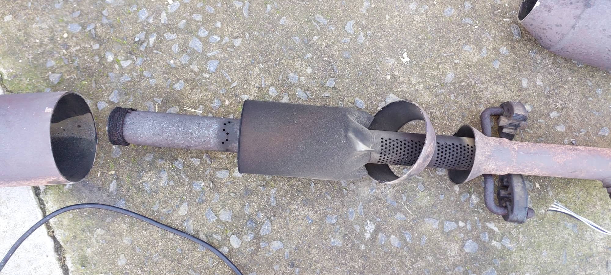
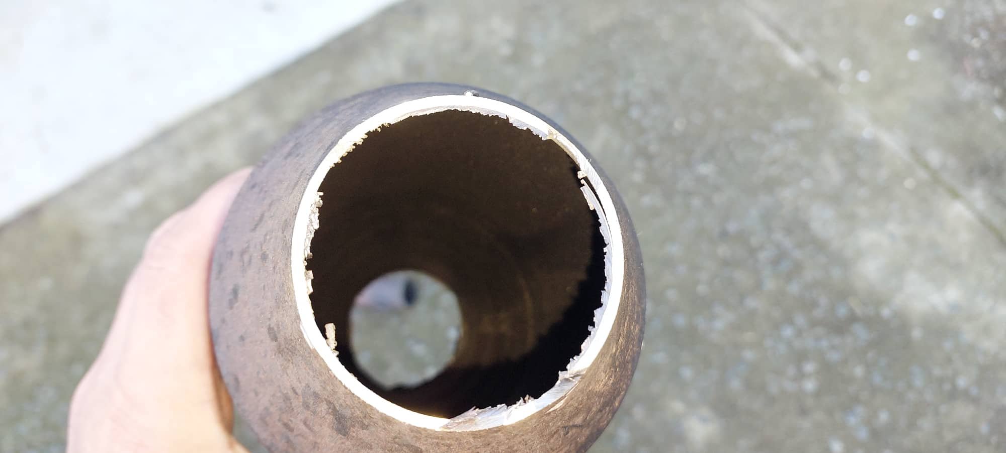
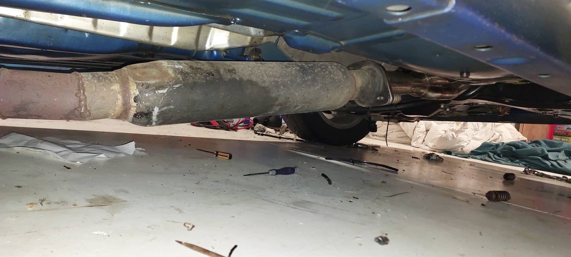
I ordered a 550mm x 6" diameter barrel muffler from Adrenalin R earlier in the week. It turned up today, and I'm glad I didnt try stuff a 7" one in there! It should be pretty good and tuck up nicely, but I need to trim the heat shields a bit where they taper in around the factory muffler. So I'm gonna take this over to @Geophy tomorrow to get welded onto the flange and front piece of pipe. Then during the week next week @Stu has said I can borrow his spare tig setup, so I can tack together the rest from there. However I dont think I'll try fully weld it myself. At the moment with the muffler just stuffed onto the front pipe, so not sealing at all, it sounds remarkably like a VW beetle or something haha. I'll double check the cam timing over the weekend on this 1300 motor, something is seriously wrong with it. It can barely rev out. Hopefully it's the cam timing and not a damaged valve guide or something. Would still like to use that head if it's alright, and would be interesting to see how the 1300 motor goes. Currently it's a bit too loud still, but defnitely a lot better than without it. Also amusing was chopping up the factory pipe to see what's inside - weird stuff, and no packing. Had I just blown all of the packing out of it perhaps? Speaking of such things, this is what the cat converter looked like... Not even any trace of it left haha.

-
Far out, this is shaping up good! Love it.
-
Everyone needs a supertrapp in their life
-
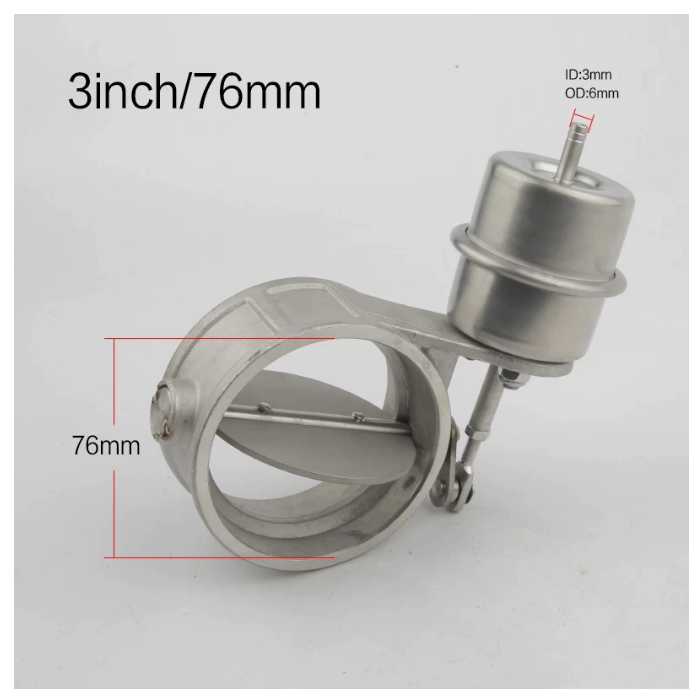
The factory vitz rs rear muffler has a spring loaded flap inside it. So its a triple pass muffler until the pressure gets high enough, then the flap opens making it straight through. Pretty cool. A lot of toyota mufflers do this on later stuff (like altezza, celica etc) You can buy mufflers like this from Chase. But not sure if in 3". Also the available space at the back really needs a circular muffler not an oval one. But yeah, also it might not be even necessary. The carina ended up way quieter than expected with straight through mufflers. EDIT: These are the type I was thinking of, not to spendy or heavy. Looks like this one might even have a position sensor on it? EDIT2: Oh nah, it's just got a 3 wire plug so it can reverse the polarity to open or close it. If I wasnt using e-throttle, and could mount a position sensor. You could control a DC motor like that with the H bridge in the ECU that normally runs e-throttle, to get a variable position on it. But, I guess you only ever really want it open or closed. meh. EDIT 3: Ones like this could be good, just use a VSV to give it vacuum or not. Then no electronics near it to cause issues. EDIT 4: This one specifically could earn its keep, hhmm! Might get one. It's normally open, and only needs around 3-5psi to start shutting. So even with crappy vac source from ITB it will be fine.
-
Oddly any variable/adjustable exhaust like the varex ones are illegal in NZ. Unless factory fitted. At least thats my interpretation of it. It would be a nice solution, you can buy cheaper exhaust throttle type things that just close a butterfly.
-
He looks good out of one too
-
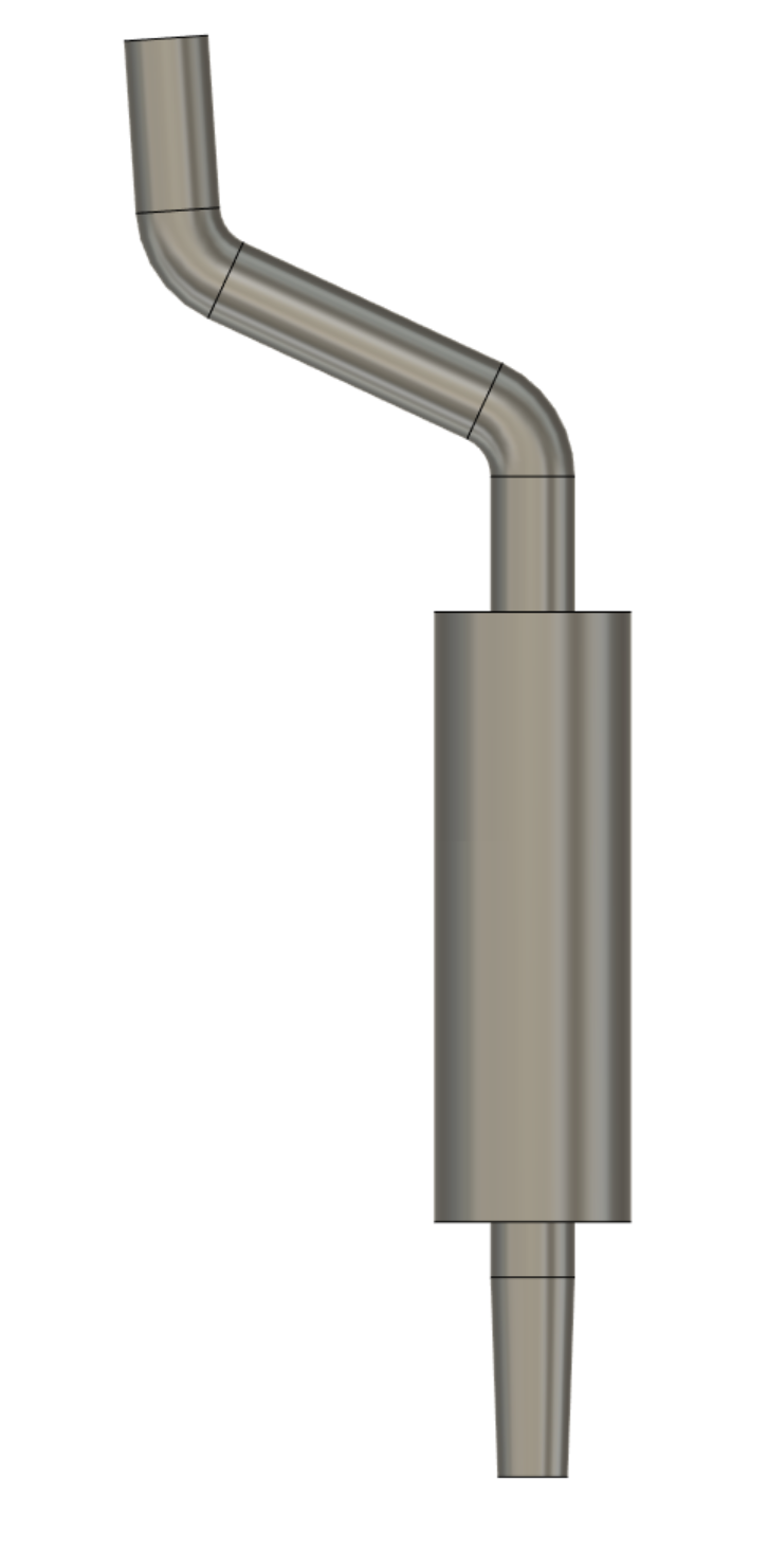
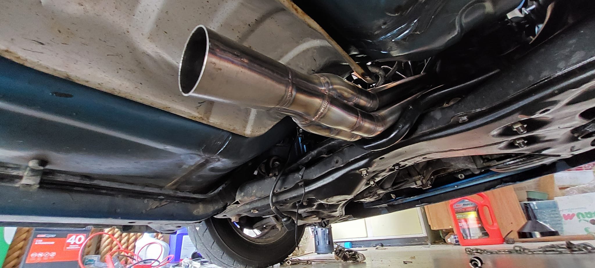
Exhaust investigation. I think this really is one of those scenarios where, if you want a big exhaust that flows good and doesnt make your ears bleed. There's just no way around it. You have to spend the money. I've been tempted to bitch out and just put a 2.5" exhaust on it, or smaller. As smaller pipe is a bit cheaper and it will help keep it quieter. But I think this would be a real disservice to the amazing work KPR has done on the manifold, and others who've contributed to see this project progress! I'd also always be wondering "what if" and I'd hate to save a tiny bit of money and then potentially leave some power on the table. Even if it's not much. Also, this car has an absolutely gigantic amount of room and a super easy exhaust path. So if any of my cars will ever be capable of it, this is it. haha. So, first things first I had a Toyota flexible flange ball joint thingy welded to the 2.5" part of the end of the manifold. All fits up great. (Thanks Rhys) The other half of the flange that I need to weld to the remaining section of the manifold. This was still on the exhaust on the Carina. So I yanked that out, and figured I may as well jam the whole thing on and see how loud it is with a long pipe and a single resonator on it. Answer: still way too loud, haha. I wont be getting invited to any Christmas parties at this rate. This is a fairly flogged out Chase muffler that I've repacked once because all of the innards flew out. So not exactly the pinnacle of muffler performance. However it's also worth noting that it basically sounds the same, but quieter. If it can end up quieter but still sound like this, it's gonna be cool as! So I think the only way I'll manage to get away with anything decent will be to use good mufflers. Adrenalin R seems the option of choice for everyone that ever has trouble keeping the noise down. They are expensive, but so is buying cheaper stuff then having to redo it. So my current plan is to buy the longest straight through muffler, and mount it not far after the extractors. Then see how obnoxious it is. If it's awful, then I can still put another muffler on the back. Even if it's a cheap/shitty/restrictive twin loop one or something. However this leaves the option of being able to easily fit a side pipe for drags and so on, if I put a second flange in a good place. I measured how much space I've got after the extractors, and thankfully I'll easily fit a 550mm long muffler in there. I'll double check that a 7" diameter barrel will fit though, once I've got the taller engine block back in. 8" or 6" diameter barrels are also optional sizes . It would be good if I could fit 8", I'm guessing it would keep the noise down a bit better. The next steps are to get the second half of the flange mounted to the expansion cone, then weld some amount of 3" pipe onto the back of that. Then order a muffler, and get that welded in place. Then work on the next section. Might take a while this way, but will get there. I'm not quite sure what radius the 3" bends will be, but it looks like there's still plenty of allowance anyway. I quickly sketched up the dimensions of everything. Should be sweet. I might actually be able to sneak a second short muffler in that intermediate bend part too, depending on radius of the bends.
-
Be sure to record all of the numbersand post them here... maybe some graphs?
-
Did Jonno tune this?
-
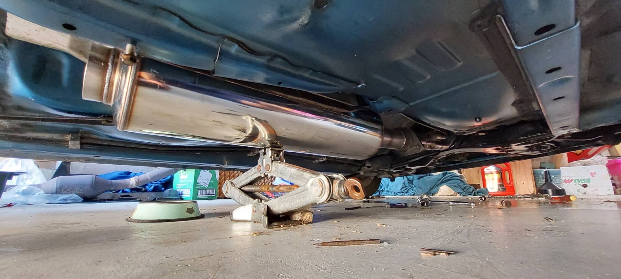
Sooooo.... 56 pages and 651 days later, I'm finally putting an exhaust on it @kpr's awesome awesome awesome manifold fits up great. Thankfully it could fit in from under the car, without having to undo engine mounts or anything. It sits a little too low with the 1300cc motor in there, as the block is shorter. But it will be perfecto once I get a new prius engine. Which I'll get next week. Enjoy some tractor noises!
-
I was like "Oh cool a thread about a nice low km modern car, will be nice to see some pics of it going on adventures etc even if it just stays standard and doesnt need any work" Next few posts down:
- 15 replies
-
- 13
-

-

-

-
holy shit haha. that's outrageously expensive. Is there anything special about it to justify the price?
-
I set the intake cam 1 tooth back on the chain, and then used a small stopper inside the pulley to limit the last few degrees of travel. So the stopper limits the total travel to around 37 degrees instead of 40ish, and moving the cam back 1 tooth means it gets to +17 deg instead of +37. So this gets as close as it could to the top of the piston without modification. My new home position for the cam is effectively -20 deg However it worked out well, because at high rpm I'm actually retarding the cam further than it would normally be able to go. Effectively at -7 degrees by 9000rpm. And yes it says "forged rods" on wikipedia but I dont think 1NZFXE has anything special compared to normal 1NZ. Just "wikifacts" they are still pencil sized haha.
-
10.5:1 static comp, dynamic varies with vvti.
-
Im just tossing this up. Because the bellhousing situation with the newer motor isnt really as bad as I first moaned about. What I thought was a missing top bolt that is supposed to go through to my engine simply doesnt exist on the normal block either. So there are only two bolts that arent great. One, instead of just drilling this time. I could drill smaller and use a tap, and it would be super legit. The other side is less great though, but could be figured out. The dowels hold it all correctly, and Ithink ive given it enough of a beating to prove it works well enough. I guess im concerned that the only earlier motors I can find look a bit grotty and have been sitting on trademe for a looooong time. Where as the newer motors, I know exactly what im in for. With a newer motor theres less chance of spending the contributed money on a motor that might be a dud. Also I can go back to dodsons and see if they will sell me another one for a little cheaper without warranty again. No such luck with the older motors from a different wrecker, that are more expensive to start with. And might be fucked. Hmmm.
-
No at the moment it's considerably slower than when I had the standard cams with ITB on. Something is wrong but I'm quite sure what. I've checked plugs and cam timing and injectors. Seems like it's running on all cylinders fine. I think I might need to do a compression test. Maybe one or more of the valves is leaking a little. It actually kind of feels like when I'm doing the VVTI tests, and you set the cam to 40 degrees advance. When you do this the motor can barely get to the redline, it feels so sluggy. Currently it feels like that everywhere. I am wondering if it would perform a lot better with the intake cam 1 tooth back on the chain, like my previous motor had. It's also got a more grumpy idle, like what happens when you advance the cam too much at idle. Weird. I guess it still could possibly be 1 tooth out on the crank end of the chain. As that's hard to check 100% without the cover off. Dunno. I've exhausted the easy options and CBF is setting in. I might just pull the exhaust out and start planning for the new manifold.
-
Yeah the idle is a bit rough as well, basically I've got a 4k with a 3/4 race cam.
-
I got the 1300cc motor running with the big cams/ITB/etc. Something is definitely quite wrong at the moment! It feels like 1/4 throttle compared to before. For some reason, its super garbage right now. More than can be explained by the lower displacement and compression. I'm thinking it's either running on 3 cylinders at higher load or maybe the cam timing is wrong. The coloured links on the timing chain were very faint. It's possible that I'm a tooth out on the crank. Which is annoying, because its a big pain in the ass to check it or adjust it. It's only another week until I should have $$ for another Prius motor turning up. Not sure if I can be bothered troubleshooting this a bunch in the meantime.
-
Is there line of sight from this exhaust pipe to your radiator? It might just be beaming radiant heat directly into your radiator. Which being all alloy, it just loves to soak up. Should be pretty easy to test, just need pretty much anything that breaks line of sight between the parts will help. With an air gap away from both parts ideally. Thin shiny stainless steel sheet would be ideal if there's any around you can just cable tie to your engine bay or something.
-
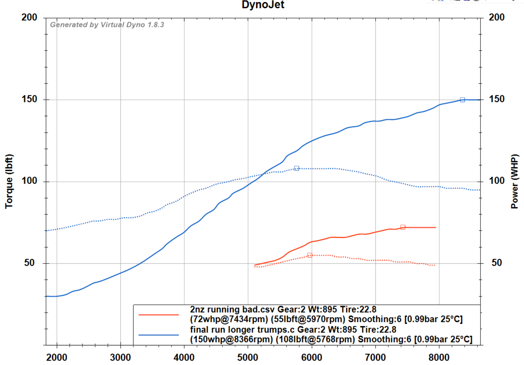
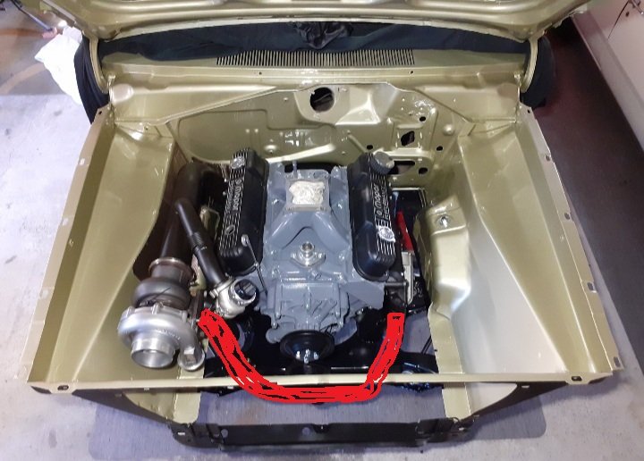
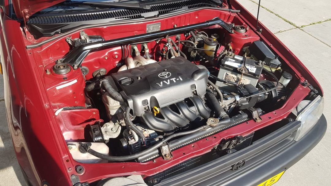
Once my new motor is here, I'll get it fitted up and get a brace welded on to somewhere sturdy on the block. Which might also double as something to help hold the rods in Someone on Instagram messaged me to say they made a long pipe setup for their starlet which has a 1NZ. Quite a cool install, like so: In his words: "The stock 1nz made 105 hp on de dyno and in combination with a 2.5 inch exhaust and manifold, it ran 127 hp" So that's a pretty epic gain! Especially with the dunga intake manifold still on it. This doesnt imply I'd get the same % amount of gain when I'm already making more power, but it looks promising to at least get a bit more zing out of it. Still need to buy some parts to finish an exhaust, once this arrives. -straight pipe -bends -flexi join -o2 sensor bung (Pretty sure I've got one somewhere, but no idea where) -muffler(s) Does anyone have any reccomendations on good price point for reasonable quality stuff? I'm thinking since it's going to have a big pipe on it, probably need to spend some money on quality parts for mufflers to help keep the noise down a bit.
-
Far out. I can honestly say I never thought I'd have a fabricated exhaust manifold of this quality, on ANY car, and I certainly never imagined I'd have one like this on the Echo haha. Cant express how awesome this is. Cant wait to get it finished and fired up!
-
Wow! Probably cant get a working T50 for that anymore haha
-
New VVTI install looks awesome. Reading first page of this thread, posted in 2007 - when you said you've had the car for a couple of years. Must be coming up to nearly 20 years with this car!
-
Far out, looks so good! It doesnt look so worryingly long now that the 4 pipes are on there haha. Looks more like it belongs on an F1 car than an Echo

.jpg.697f054f02d9346ade8c17faa8b8d2b8.jpg)